Panasonic Air Conditioner - baneh.com · − Powerful mode to reach the desired room temperature...
52
1 Features 2 2 Functions 3 2.1. Remote Control 3 2.2. Indoor Unit 4 2.3. Outdoor Unit 5 3 Product Specifications 6 3.1. CS-A18DKS CU-A18DKS 6 3.2. CS-A24DKS CU-A24DKS 8 4 Dimensions 10 4.1. Indoor Unit & Remote Control 10 4.2. Outdoor Unit 11 5 Refrigeration Cycle Diagram 12 6 Block Diagram 13 7 Wiring Diagram 14 7.1. CS-A18DKS CU-A18DKS 14 ' 2004 Panasonic HA Air-Conditioning (M) Sdn Bhd (11969-T). All rights reserved. Unauthorized copying and distribution is a violation of law. CS-A18DKS CU-A18DKS CS-A24DKS CU-A24DKS 7.2. CS-A24DKS CU-A24DKS 15 8 Operation Details 16 8.1. Heating Operation 16 8.2. Cooling Operation 17 8.3. Soft Dry Operation 18 8.4. Automatic Operation 19 8.5. Operation Control 20 8.6. Indoor Fan Speed Control 27 8.7. Outdoor Fan Speed Control 29 8.8. Vertical Airflow Direction Control 29 8.9. Horizontal Airflow Direction Control 30 8.10. Powerful Operation 31 8.11. Quiet Operation 31 8.12. Ionizer Operation 33 8.13. Timer Control 34 Air Conditioner CONTENTS Page Page Order No. MAC0501010C3
Transcript of Panasonic Air Conditioner - baneh.com · − Powerful mode to reach the desired room temperature...
1 Features 2 2 Functions 3
2.1. Remote Control 3
2.2. Indoor Unit 4
2.3. Outdoor Unit 5
3 Product Specifications 6 3.1. CS-A18DKS CU-A18DKS 6
3.2. CS-A24DKS CU-A24DKS 8
4 Dimensions 10 4.1. Indoor Unit & Remote Control 10
4.2. Outdoor Unit 11
5 Refrigeration Cycle Diagram 12 6 Block Diagram 13 7 Wiring Diagram 14
7.1. CS-A18DKS CU-A18DKS 14
© 2004 Panasonic HA Air-Conditioning (M) Sdn Bhd(11969-T). All rights reserved. Unauthorized copyingand distribution is a violation of law.
CS-A18DKS CU-A18DKSCS-A24DKS CU-A24DKS
7.2. CS-A24DKS CU-A24DKS 15
8 Operation Details 16 8.1. Heating Operation 16
8.2. Cooling Operation 17
8.3. Soft Dry Operation 18
8.4. Automatic Operation 19
8.5. Operation Control 20
8.6. Indoor Fan Speed Control 27
8.7. Outdoor Fan Speed Control 29
8.8. Vertical Airflow Direction Control 29
8.9. Horizontal Airflow Direction Control 30
8.10. Powerful Operation 31
8.11. Quiet Operation 31
8.12. Ionizer Operation 33
8.13. Timer Control 34
Air Conditioner
CONTENTS Page Page
Order No. MAC0501010C3
8.14. Random Auto Restart Control 35
8.15. Remote Control Signal Receiving Sound 35
9 Operating Instructions 36 10 Installation Instructions 42
10.1. Safety Precautions 42
10.2. Indoor Unit 45
10.3. Outdoor Unit 49
11 2-way, 3-way Valve 52 11.1. Evacuation of the Equipment (For Europe & Oceania
Destination) 53
11.2. Air Purging of the Piping and Indoor Unit 59
12 Servicing Information 65 12.1. Indoor Electronic Controllers Removal Procedures 65
12.2. Cross Flow Fan and Indoor Fan Motor Removal
Procedures 66
12.3. Remote Control Reset 67
12.4. Auto OFF/ON Button 68
13 Troubleshooting Guide 69
• High efficiency. • Compact design. • Wider range of horizontal discharge air. • Air Filter with function to reduce dust and smoke. • Automatic air swing and manual adjusted by Remote
Control for horizontal and vertical airflow. • Long installation piping up to 25 meter. • Supersonic Air Purifying System with SUPER alleru-buster.
− Inactive various harmful airbone elements includingallergens, viruses and bacteria.
− Generated supersonic waves enhance the ability tocollect dust and dirt in the air.
• Quality Improvement − Random auto restart after power failure for safety restart
operation. − Gas leakage detection. − Prevent Compressor reverse cycle. − Inner protector to protect Compressor. − Noise prevention during soft dry operation. − Blue coated Condenser for high resistance to corrosion. − Anti-dew formation control (Cooling & Soft Dry). − Overload Protection Control (Heating).
− Outdoor Fan Control. − Compressor High Pressure Control.
• Operation Improvement − Quiet mode to provide quiet operation. − Powerful mode to reach the desired room temperature
quickly. − Ionizer control for generating negative ion in discharge
air.
13.1. Refrigeration cycle system 69
14 Technical Data 71 14.1. Thermostat characteristics 71
14.2. Operation characteristics 72
15 Exploded View (Indoor Unit) 74 15.1. CS-A18DKS CS-A24DKS 74
16 Replacement Parts List (Indoor Unit) 75 16.1. CS-A18DKS CS-A24DKS 75
17 Exploded View (Outdoor Unit) 76 17.1. CU-A18DKS CU-A24DKS 76
18 Replacement Parts List (Outdoor Unit) 77 18.1. CU-A18DKS CU-A24DKS 77
19 Electronic Circuit Diagram 78 19.1. Indoor Unit & Outdoor Unit 78
19.2. Remote Control 84
19.3. Print Pattern Indoor Unit Printed Circuit Board 85
19.4. Print Pattern Indicator & Receiver Printed Circuit Board 86
19.5. Print PatternOutdoor Unit Printed Circuit Board 87
− 24-hour timer setting.
• Serviceability Improvement − Removable and washable Front Panel.
1 Features
2
CS-A18DKS CU-A18DKS / CS-A24DKS CU-A24DKS

2 Functions2.1. Remote Control
Operation Start/StopOFF / ON
Room Temperature SettingTEMP.
Operation Mode Selection
AUTO Automatic Operation
COOL Cooling Operation HEAT Heating Operation Mode
DRY Soft Dry Operation
MODE
Time / Timer Setting
Hours and minutes setting.
Clock Setting
Current time setting.
Ionizer Operation Start/Stop
Indoor Fan Speed SelectionFAN SPEED
FAN Low Fan Speed FAN Medium Fan Speed FAN High Fan Speed AUTO Automatic Fan Speed
FAN
Airflow Direction Control
24-hour, OFF / ON Real Timer Setting.
ON-TIMEROFF-TIMER
Timer Operation Selection
SETCANCEL Timer Operation Set / Cancel
ON Timer and OFF Timer setting andcancellation.
CLOCK
AIR SWING
Vertical Automatic AirflowDirection Control and ManualAirflow Direction Control (5 stages of adjustment).
Horizontal Automatic AirflowDirection Control and ManualAirflow Direction Control (5 stages of adjustment).
Powerful Operation Start/StopPOWERFUL
Quiet Operation Start/StopQUIET
Cooling, Soft Dry Operation. Increase or decrease set temperature
(16°C to 30°C)Automatic Operation Operation with 2°C higher than
standard temperature. Operation with standard temperature. Operation with 2°C lower than
standard temperature.
<
<
3
CS-A18DKS CU-A18DKS / CS-A24DKS CU-A24DKS

2.2. Indoor Unit
Ionizer Operation
Generate and discharge negative ion.
Random Auto Restart Control
Unit will be restarted, when resume frompower failure, at previous setting.
Anti-Freezing Control
To prevent indoor heat exchanger fromfreezing.
Indoor Fan Speed Control
Manual control fan speed(High, Medium and Low).
Automatic fan speed
Vertical airflow control can be adjustedautomatically or manually by remote control.Horizontal airflow control can be adjustedautomatically or manually by remote control.
Airflow Direction Control
Automatic Operation Button
Press for < 5 second to operate Automaticoperation mode.Use when the remotecontrol cannot be used.
Press for > 5 second to operate Coolingoperation mode and compressor forceto on (beep sound will be heard). Used when test running or servicing.
Within 20 second of Cooling operation, press continuously for > 5 second to enter various setting mode. beep, beep sound will be heard. (Used to toggle remote control signal receiving sound or select remote control transmission code.)
AUTOOFF / ON
Operation Indication Lamps (LED)
POWER (Green) ........ Lights up in operation,blinks in AutomaticOperation judging.
QUIET (Orange) ........ Lights up in QuietOperation.
TIMER (Orange) ....... Lights up in TimerSetting.
POWERFUL (Orange) .. Lights up in PowerfulOperation.
ION (Green) ........... Lights up in IonizerOperation.
SUPER ALLERU-BUSTER (Blue) ... Lights up in operation.
Operation Mode
Heating, Cooling, Soft Dry and Automatic Operation.
Powerful Operation
Reaches the desired room temperature quickly.
Timer Operation
Delay OFF/ON Timer control.
Time Delay Safety Control
Restarting is inhibited for appro. 3 minutes.
Quiet Operation
To provide quiet operation.
7 Minutes Time Save Control
To reduce the built up humidity insidethe room.
Anti-Dew Formation Control
Anti-Dew Formation Control for indoorunit discharge area.
Hot-Start Control
To prevent cold air being discharge duringHeating operation starts.
Anti Cold Draft Control
To prevent the cold draft during Heatingmode operation in thermo off condition.
4
CS-A18DKS CU-A18DKS / CS-A24DKS CU-A24DKS

2.3. Outdoor Unit
To protect compressor from reverserotation when there is an instantaneouspower failure.
60 Secs. Forced Operation Control
Once the compressor is activated, itdoes not stop within the first 60 secs.However, it stops immediately withremote control stop signal.
Overload Protector
Inner protector.
Compressor Reverse RotationProtection Control To prevent frosting at outdoor heat
exchanger during Heating Operation.
Deice Control
When the unit is switched to OFFduring Heating Operation, 4-way valvestays at Heating position for 5 minutes.
4-Way Valve Control
Outdoor Fan Operation Control
6-pole induction motor (2 speed).
For Cooling or Soft Dry operationHi-speed ............. When outdoortemperature reaches to 31°C.Lo-speed ............. When outdoortemperature reaches to 29°C.For Heating operationHi-speed ............. When outdoortemperature reaches to 13.5°C.Lo-speed ............. When outdoortemperature reaches to 15.5°C.For Over-heating Protection, the Fan isswitched ON or OFF depending on thepiping temperature and the outdoortemperature.
5
CS-A18DKS CU-A18DKS / CS-A24DKS CU-A24DKS

3 Product Specifications3.1. CS-A18DKS CU-A18DKS
Unit CS-A18DKS CU-A18DKS
Power Source (Phase, Voltage, Cycle) , V, Hz Single, 220, 60
Cooling Capacity kW (BTU/h) 4.27 (14,600)kcal/h (Fri/h) 3,670
Heating Capacity kW (BTU/h) 5.62 (19,200)kcal/h (Fri/h) 4,830
Moisture Removal l/h (Pint/h) 0.7 (1.5)
Airflow Method OUTLET
INTAKE
SIDE VIEW TOP VIEW
Air Volume Lo m3/min (cfm) Cooling; 13.0 (460) 30.4 (1,070)Heating; 13.9 (490)
Me m3/min (cfm) Cooling; 14.5 (510) Heating; 14.5 (510)
Hi m3/min (cfm) Cooling; 15.3 (540) 52.7 (1,860)Heating; 16.0 (560)
SHi m3/min (cfm) Cooling; 16.0 (560) Noise Level dB (A) Cooling; High 43, Low 38 Cooling; High 54
Heating; High 42, Low 38 Heating; High 55Electrical Data Input Power kW Cooling; 2.04
Heating; 1.71Running Current A Cooling; 9.5
Heating; 7.9EER W/W (BTU/hW) Cooling; 2.09 (7.16)COP W/W (BTU/hW) Heating; 3.29 (11.23)Starting Current A 47.0
Piping Connection Port(Flare piping)
inchinch
G ; Half Union 1/2L ; Half Union 1/4
G ; 3-way valve 1/2L ; 3-way valve 1/4
Pipe Size(Flare piping)
inchinch
G ; (gas side) 1/2L ; (liquid side) 1/4
G ; (gas side) 1/2L ; (liquid side) 1/4
DrainHose
Inner diameter mm 12 Length mm 650
Power Cord Length m 1.9 Number of core-wire 3 (2.5 mm2)
Dimensions Height inch (mm) 10 - 13/16 (275) 29 - 17/32 (750)Width inch (mm) 39 - 9/32 (998) 34 - 7/16 (875)Depth inch (mm) 9 - 1/16 (230) 13 - 19/32 (345)
Net Weight lb (kg) 24 (11.0) 120 (54.5)Compressor Description Rotary (1 cylinder)
rolling piston typeMotor Type Induction (2-poles)Rated Output kW 1.2
6
CS-A18DKS CU-A18DKS / CS-A24DKS CU-A24DKS

Unit CS-A18DKS CU-A18DKSAir Circulation Description Cross-flow Fan Propeller Fan
Material ASHT-18 PPMotor Type Transistor (8-poles) Induction (6-poles)Input W 40.0 148.4Rated Output W 30 72Fan Speed Low rpm Cooling; 1,190 490
Heating; 1,270Medium rpm Cooling; 1,320
Heating; 1,320High rpm Cooling; 1,400 850
Heating; 1,460SuperHigh rpm Cooling; 1,460
Heat Exchanger Description Evaporator CondenserTube material Copper CopperFin material Aluminium (Pre Coat) AluminiumFin Type Slit Fin Corrugated FinRow / Stage (Plate fin configuration, forced draft)
2 × 15 2 × 28FPI 21 16Size (W × H × L) mm 810 × 315 × 25.4 827.6
862.2× 711.2 × 44
Refrigerant Control Device Capillary TubeRefrigeration Oil (cm3) SUNISO 4GDID or ATMOS
M60 or ATMOS 56MRefrigerant (R-22) g (oz) 1,550 (54.7)Thermostat Protection Device Overload ProtectorCapillary Tube Length mm Cooling; 787, Heating; 560
Flow Rate l/min Cooling; 12.0, Heating; 21.8Inner Diameter mm Cooling; 1.6, Heating; 2.2
Air Filter MaterialStyle
P.P.Honeycomb
Capacity Control Capillary TubeCompressor Capacitor µF, VAC 40 µF, 400/440VACFan Motor Capacitor µF, VAC 3.5 µF, 440VAC
Note: • Specifications are subject to change without notice for further improvement.
7
CS-A18DKS CU-A18DKS / CS-A24DKS CU-A24DKS

3.2. CS-A24DKS CU-A24DKSUnit CS-A24DKS CU-A24DKS
Power Source (Phase, Voltage, Cycle) , V, Hz Single, 220, 60
Cooling Capacity kW (BTU/h) 5.48 (18,700)kcal/h (Fri/h) 4,710
Heating Capacity kW (BTU/h) 7.65 (26,100)kcal/h (Fri/h) 6,580
Moisture Removal l/h (Pint/h) 1.2 (2.5)
Airflow Method OUTLET
INTAKE
SIDE VIEW TOP VIEW
Air Volume Lo m3/min (cfm) Cooling; 14.2 (500) 30.4 (1,070)Heating; 15.4 (540)
Me m3/min (cfm) Cooling; 16.4 (580) Heating; 16.4 (580)
Hi m3/min (cfm) Cooling; 17.4 (610) 52.7 (1,860)Heating; 18.2 (640)
SHi m3/min (cfm) Cooling; 18.2 (640) Noise Level dB (A) Cooling; High 47, Low 41 Cooling; High 55
Heating; High 46, Low 41 Heating; High 55Electrical Data Input Power kW Cooling; 3.04
Heating; 2.73Running Current A Cooling; 14.1
Heating; 12.8EER W/W (BTU/hW) Cooling; 1.80 (6.15)COP W/W (BTU/hW) Heating; 2.80 (9.56)Starting Current A 63.0
Piping Connection Port(Flare piping)
inchinch
G ; Half Union 5/8L ; Half Union 1/4
G ; 3-way valve 5/8L ; 3-way valve 1/4
Pipe Size(Flare piping)
inchinch
G ; (gas side) 5/8L ; (liquid side) 1/4
G ; (gas side) 5/8L ; (liquid side) 1/4
DrainHose
Inner diameter mm 12 Length mm 650
Power Cord Length m 1.9 Number of core-wire 3 (2.5 mm2)
Dimensions Height inch (mm) 10 - 13/16 (275) 29 - 17/32 (750)Width inch (mm) 39 - 9/32 (998) 34 - 7/16 (875)Depth inch (mm) 9-1/16 (230) 13 - 19/32 (345)
Net Weight lb (kg) 24 (11.0) 140 (63.5)Compressor Description Rotary (1 cylinder) rolling
piston typeMotor Type Induction (2-poles)Rated Output kW 1.8
8
CS-A18DKS CU-A18DKS / CS-A24DKS CU-A24DKS

Unit CS-A24DKS CU-A24DKSAir Circulation Description Cross-flow Fan Propeller Fan
Material ASHT-18 PPMotor Type Transistor (8-poles) Induction (6-poles)Rated Output W 30 72Fan Speed Low rpm Cooling; 1,280 490
Heating; 1,380Medium rpm Cooling; 1,480
Heating; 1,480High rpm Cooling; 1,570 850
Heating; 1,630SuperHigh rpm Cooling; 1,630
Heat Exchanger Description Evaporator CondenserTube material Copper CopperFin material Aluminium (Pre Coat) AluminiumFin Type Slit Fin Corrugated FinRow / Stage (Plate fin configuration, forced draft)
2 × 15 2 × 28FPI 21 16Size (W × H × L) mm 810 × 315 × 25.4 827.6
862.2× 711.2 × 44.0
Refrigerant Control Device Capillary TubeRefrigeration Oil (cm3) SUNISO 4GDID or ATMOS
M60 or ATMOS 56MRefrigerant (R-22) g (oz) 1,840 (65.0)Thermostat Protection Device Inner ProtectorCapillary Tube Length mm Cooling; 591, Heating; 762
Flow Rate l/min Cooling; 18.4, Heating; 28.1Inner Diameter mm Cooling; 1.8, Heating; 2.6
Air Filter MaterialStyle
P.P.Honeycomb
Capacity Control Capillary TubeCompressor Capacitor µF, VAC 60 µF, 400/440VACFan Motor Capacitor µF, VAC 3.5 µF, 440VAC
Note: • Specifications are subject to change without notice for further improvement.
9
CS-A18DKS CU-A18DKS / CS-A24DKS CU-A24DKS

4 Dimensions4.1. Indoor Unit & Remote Control4.1.1. CS-A18DKS CS-A24DKS
10
CS-A18DKS CU-A18DKS / CS-A24DKS CU-A24DKS

4.2. Outdoor Unit4.2.1. CU-A18DKS CU-A24DKS
11
CS-A18DKS CU-A18DKS / CS-A24DKS CU-A24DKS

5 Refrigeration Cycle Diagram
12
CS-A18DKS CU-A18DKS / CS-A24DKS CU-A24DKS

6 Block Diagram
13
CS-A18DKS CU-A18DKS / CS-A24DKS CU-A24DKS

7 Wiring Diagram7.1. CS-A18DKS CU-A18DKS
CS-A18DKS CU-A18DKS / CS-A24DKS CU-A24DKS
14

7.2. CS-A24DKS CU-A24DKS
CS-A18DKS CU-A18DKS / CS-A24DKS CU-A24DKS
15

8 Operation Details8.1. Heating Operation • Heating operation can be set using remote control. • This operation is applied to warm the room temperature reaches the setting temperature set on the remote control. • The remote control setting temperature, which takes the reading of intake air temperature sensor, can be adjusted from 16°C
to 30°C. • During Heating operation, the compressor will stop running and restart as shown in below figure.
8.1.1. Heating Operation Time Diagram
16
CS-A18DKS CU-A18DKS / CS-A24DKS CU-A24DKS

8.2. Cooling Operation
• Cooling operation can be set using remote control. • This operation is applied to cool down the room temperature reaches the setting temperature set on the remote control. • The remote control setting temperature, which takes the reading of intake air temperature sensor, can be adjusted from 16°C
to 30°C. • During cooling operation, the compressor will stop running and restart as shown in below figure.
8.2.1. Cooling Operation Time Diagram
17
CS-A18DKS CU-A18DKS / CS-A24DKS CU-A24DKS

8.3. Soft Dry Operation
• Soft Dry operation can be set using remote control. • Soft Dry operation is applied to dehumidify and to perform a gentle cooling to the room. • This operation starts when the intake air temperature sensor reaches the setting temperature on the remote control. • When operation begins, Soft Dry will be switched ON for a maximum 10 minutes, then Soft Dry operation will be turned OFF
for a minimum 6 minutes. After that, the Soft Dry operation will be ON and OFF based on the setting temperature as shownin below figure.
• However after 3 minutes of compressor off, during Soft Dry OFF (within 6 minutes Soft Dry restart control), the indoor unit willstart to operate at normal Cooling mode if the intake temperature is higher than Cooling ON point.
8.3.1. Soft Dry Operation Time Diagram
18
CS-A18DKS CU-A18DKS / CS-A24DKS CU-A24DKS

8.4. Automatic Operation • Automatic operation can be set using remote control. • This operation starts to operate with indoor fan at SLo speed for 25 seconds to judge the intake air temperature. • After judged the temperature, the operation mode is determined by refering to the below standard.
• Then, the unit start to operate at determined operation mode, until it is switched off using remote control, with the settingtemperature as shown in below table.
• Operation mode will be determine again for judgement after 1 hour of operation, if the room temperature reaches to settemperature and compressor off time is over 7 minutes 30 seconds continuously.
The present mode will be continued, if the room temperature does not reach to set temperature (Compressor keeps running) eventhrough after1 hour from automatic operation mode started.
Present Judgement Next ModeMode Cooling Soft Dry Heating
O OCooling 23°C Cooling (Judgement: Not Applicable (Judgement:
Heating 23°C & Above) Below 23°C)
O OSoft Dry 20°C Soft Dry Not Applicable (Judgement: (Judgement:
Heating 20°C & Above) Below 20°C)
O OHeating Cooling (Judgement: Not Applicable (Judgement:
25°C Heating 25°C & Above) Below 25°C)
• Automatic Set TemperatureFor each operation, set temperature will automaticlly set as shown below.
• The setting temperature for all the operations can be changed one level up or one level down from the standard temperatureas shown in below table by pressing on the temperature up or temperature down button at remote control.
Operation Hi (Standard) Lo(+2°C) (±0°C) (-2°C)
Cooling 27°C 25°C 23°CSoft Dry 24°C 22°C 20°CHeating 23°C 21°C 19°C
• The operation mode judging temperature and standard setting temperature can be increased by 2°C permanently, by open thecircuit of JX1 at indoor electronic controller.
19
CS-A18DKS CU-A18DKS / CS-A24DKS CU-A24DKS

8.5. Operation Control
8.5.1. Restart Control (Time Delay Safety Control) • When the thermo-off temperature (temperature which compressor stops to operate) is reached during:-
− Cooling/Heating operation - the compressor stops for 3 minutes (minimum) before resume operation. − Soft Dry operation - the compressor stops for 6 minutes (minimum) before resume operation.
• If the operation is stopped by the remote control, the compressor will not turn on within 3 minutes from the moment operationstop, although the unit is turn on again within the period.
• This phenomenon is to balance the pressure inside the refrigerant cycle.
8.5.2. Compressor Reverse Rotation Protection Control • If the compressor is operating continuously for 5 minutes or longer and the temperature difference between intake air and
indoor heat exchanger is 2.5°C (cooling mode)/5°C (heating mode) or less for continuous 2 minutes, compressor will stop andrestart automatically.
• Time Delay Safety Control is activated before the compressor restart.
T = Intake air temperature - Indoor heat exchanger temperature • This is to prevent compressor from rotate reversely when there is an instantaneous power failure.
20
CS-A18DKS CU-A18DKS / CS-A24DKS CU-A24DKS

(For 8.5.3. to 8.5.7. information applies only to Cooling and Soft Dry Operation)
8.5.3. 7 Minutes Time Save Control • The compressor will start automatically if it has stopped for 7 minutes and the intake air temperature falls between the
compressor ON temperature (A) and compressor OFF temperature (B) during the period. • This phenomenon is to reduce the built up humidity inside a room.
8.5.4. 60 Seconds Forced Operation • Once the air conditioner is turned on, the compressor will not stop within 60 seconds in a normal operation although the intake
air temperature has reached the thermo-off temperature. However, force stop by pressing the OFF/ON operation button at theremote control is permitted.
• The reason for the compressor to force operate at minimum 60 seconds is to allow the refrigerant oil run in a full cycle andreturn back to the outdoor unit.
8.5.5. Starting Current Control • When the compressor, outdoor fan motor and indoor fan motor are simultaneously started, the indoor fan motor will start to
operate at 1.6 second later. • The reason of the difference is to reduce the starting current flow.
8.5.6. Anti-Freezing Control • If the temperature of the indoor heat exchanger falls below 2°C continuously for 4 minutes or more, the compressor turns off.
The fan speed setting remains the same. • This phenomenon is to protect the indoor heat exchanger from freezing and to prevent higher volume of refrigerant in liquid form
returning to the compressor. • Compressor will restart again when the indoor heat exchanger temperature rises to 10°C (Recovery). • Restart control (Time Delay Safety Control) will be applied in this Control if the recovery time is too short.
21
CS-A18DKS CU-A18DKS / CS-A24DKS CU-A24DKS

8.5.7. Anti-Dew Formation Control • Purpose is to prevent dew formation on indoor unit air discharge area. • When room temperature is constant (±1°C) the following conditions occur for 30 minutes continuously, anti-dew formation will
activate: − Remote Control setting temperature is less than 25°C. − Compressor is on. − Cooling operation mode. − Indoor Fan motor operate at Low fan speed or QLo.
• This control is cancelled immediately when above condition is changed. • Anti-Dew formation is control by:
1. Increasing Air Flow Volume a. Lo fan speed
Lo fan speed is changed to Lo+ after 30 min to prevent dew formation.
b. QLo fan speedDew formation may occurs at QLo cool, therefore QLo cool is operated only 1 hr 30 min (1 hr QLo, 30 min QLo +100rpm). After that, it operates at QLo +180rpm (However Quiet LED remains on).
2. NorrowingVertical Airflow Direction − During Anti-dew condensation prevention, Airflow Direction Auto-control angle change from 10° - 38° to 10° - 27° under
Cooling and Soft Dry operation mode.
22
CS-A18DKS CU-A18DKS / CS-A24DKS CU-A24DKS

− During Anti-dew condensation prevention, Airflow Direction Manual control angle change from 10°, 14°, 18°, 22°, 27° to10°, 13°, 16°, 19°, 22° under Cooling and Soft Dry operation mode.
3. NarrowingHorizontal Airflow Direction − During Anti-dew condensation prevention, Airflow Direction Auto-control angle change from 0° - 44° to 14° - 30° under
Cooling and Soft Dry operation mode.
− During Anti-dew condensation prevention, Airflow Direction Manual control angle change from 0°, 11°, 22°, 33°, 44° to14°, 18°, 22°, 26°, 30° under Cooling and Soft Dry operation mode.
(For 8.5.8. to 8.5.13. information applies only to Heating Operation)
8.5.8. Overload Protection Control • Outdoor Fan Control
− If the temperature of the Outdoor Heat Exchanger less than -3°C, Outdoor Fan is ON. The Outdoor Fan stop, when OutdoorHeat Exchanger temperature is T or more according to Outdoor Air Temperature region as table below:The Outdoor Fan restarts when the indoor heat exchanger temperature falls to 49°C.
− During starting of Heating mode and after deice, Outdoor Fan ON for 90 sec. (Hi).
23
CS-A18DKS CU-A18DKS / CS-A24DKS CU-A24DKS

• Compressor high pressure protection − If the indoor heat exchanger becomes 68°C or more, the compressor will stop and restart automatically. − Time Delay Safety Control is activated before the compressor restart.
8.5.9. 4-Way Valve Control • 4-way valve always on during Heating operation. (except deicing operation) • When the unit is switched off by remote control during Heating operation, the 4-way valve stay at Heating position for 5 minutes. • This is to prevent the refrigerant flow process sound for being occur.
8.5.10. Outdoor Fan Motor Control • When compressor stops (reaches room temperature), outdoor fan will operate for 30 seconds (forced operation). • This is to release the heat and to obtain the lowest pressure as fast as possible.
8.5.11. Hot Start Control • Hot Start Control is to prevent cool air discharge into the room when heating operation start. • When Heating operation starts, Indoor fan will not start until the indoor heat exchanger reaches 30°C as diagram shown.
• Hot start is completed when indoor heat exchanger rises to 42°C or operation over 4 minutes.
24
CS-A18DKS CU-A18DKS / CS-A24DKS CU-A24DKS

8.5.12. Anti Cold Draft Control • This operation is to prevent the Cold Draft during Heating mode operation. • The operation will start when compressor OFF (Thermo OFF) during Heating operation. • For the first 30 sec. from compressor OFF (Termo OFF), Indoor fan speed will operate accordingly to the Indoor heat exchanger
temperature as shown below:
• After 30 sec. from compressor OFF (thermo OFF), Indoor fan will run at SSLo speed only. • Anti Cold Draft Control will stop when:
− Intake temperature < set temperature. (Time Delay Safety Control 4 minutes waiting is valid) − 30 Minutes Time Save Control activates.
8.5.13. Deicing ControlDeice starts to prevent frosting at outdoor heat exchanger. • Normal Deicing
Deice operations detection commences after 60 minutes of Heating operation starts or 60 minutes after previous deiceoperation. If the TRS (Thermal Read Switch) senses the outdoor piping temperature drops to -4°C (TRS CLOSE) or less for 50sec. continuously during compressor is in operation, deice will start.(There is no detection during Outdoor Fan stops.)
• Overload DeicingDuring heating operation, if the outdoor Fan OFF duration (due to overload control) is accumulated up to 60 minutes and aftercompressor starts for 1 minutes, deicing starts.
• Deicing ends when 1. 12 minutes after deicing operation starts; 2. The outdoor piping temperature rises to 12°C.
• After deicing operation, compressor stops for 30 seconds and 4-way valve stays at cooling position for 10 seconds.
25
CS-A18DKS CU-A18DKS / CS-A24DKS CU-A24DKS

Normal Deicing Time Diagram
Overload Deicing Time Diagram
26
CS-A18DKS CU-A18DKS / CS-A24DKS CU-A24DKS

8.6. Indoor Fan Speed Control • Indoor Fan Speed can be set using remote control.
8.6.1. Fan Speed Rotation ChartFan Speed CS-A24DKS CS-A18DKS
Cool, Dry HeatSHi Hi 1460 1630Hi - 1400 1570Me Me 1320 1480Lo+ Lo 1270 1380Lo - 1190 1280Lo- Lo- 980 1070
SLo- SLo 760 830- SSLo 300 300
QSHi QHi 1360 1530QHi - 1300 1470QMe QMe 1220 1380
- QLo 1170 1280QLo - 1090 1180
8.6.2. Automatic Fan Speed Control • When set to Auto Fan Speed, the fan speed is adjusted between maximum and minimum setting as shown in the table.
− Fan speed rotates in the range of Hi and Me. − Deodorizing Control will be activated.
27
CS-A18DKS CU-A18DKS / CS-A24DKS CU-A24DKS

• Auto Fan Speed during Cooling operation: 1. Indoor fan will rotate alternately between off and on as shown in below diagram. 2. At the beginning of each compressor start operation, indoor fan will increase fan speed gradually for deodorizing purpose. 3. For the first time the compressor operate, indoor fan will be switched to Hi fan speed from SLo after 70 seconds from the
start of compressor. This cause the room temperture to achieve the setting temperature quickly. 4. During compressor stop, indoor fan will operate at SLo for the beginning 20 seconds to prevent higher volume of refrigerant
in liquid form returning to the compressor. 5. After the compressor at turn off condition for 3 minutes, indoor fan will start to operate at SLo to circulate the air in the room.
This is to obtain the actual reading of the intake air temperature. 6. When the compressor resume operation, indoor fan will operate at Me fan speed (after 70 seconds from the restart of
compressor) to provide comfort and lesser noise environment.
• Auto Fan Speed during Soft Dry operation: 1. Indoor fan will rotate alternately between off and Lo-. 2. At the beginning of each compressor start operation, indoor fan will increase fan speed gradually for deodorizing purpose. 3. When compressor at turn off condition for 6 minutes, indoor fan will start fan speed at Lo- to circulate the air in the room.
This is to obtain the actual reading of intake air temperature.
• Auto Fan Speed during Heating operation. 1. Indoor fan will rotate in the range of SLo → Me according to the heat exchanger temperature.
28
CS-A18DKS CU-A18DKS / CS-A24DKS CU-A24DKS
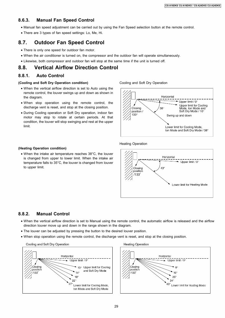
(Cooling and Soft Dry Operation condition) • When the vertical airflow direction is set to Auto using the
remote control, the louver swings up and down as shown inthe diagram.
• When stop operation using the remote control, thedischarge vent is reset, and stop at the closing position.
• During Cooling operation or Soft Dry operation, indoor fanmotor may stop to rotate at certain periods. At thatcondition, the louver will stop swinging and rest at the upperlimit.
(Heating Operation condition) • When the intake air temperature reaches 38°C, the louver
is changed from upper to lower limit. When the intake airtemperature falls to 35°C, the louver is changed from louverto upper limit.
Cooling and Soft Dry Operation
Heating Operation
8.6.3. Manual Fan Speed Control • Manual fan speed adjustment can be carried out by using the Fan Speed selection button at the remote control. • There are 3 types of fan speed settings: Lo, Me, Hi.
8.7. Outdoor Fan Speed Control • There is only one speed for outdoor fan motor. • When the air conditioner is turned on, the compressor and the outdoor fan will operate simultaneously. • Likewise, both compressor and outdoor fan will stop at the same time if the unit is turned off.
8.8. Vertical Airflow Direction Control8.8.1. Auto Control
8.8.2. Manual Control • When the vertical airflow direction is set to Manual using the remote control, the automatic airflow is released and the airflow
direction louver move up and down in the range shown in the diagram. • The louver can be adjusted by pressing the button to the desired louver position. • When stop operation using the remote control, the discharge vent is reset, and stop at the closing position.
29
CS-A18DKS CU-A18DKS / CS-A24DKS CU-A24DKS

8.9.1. Auto Control • When the horizontal airflow direction is set to Auto using the
remote control, the vanes swings left and right as shown inthe diagram.
• When stopped with remote control, the discharge vane isreset, and stop at the reset position.
• During Cooling operation or Soft Dry operation, indoor fanmotor may stop to rotate at certain periods. At thatcondition, the vane will stop swinging and rest at 22° angle.
• When the horizontal airflow direction is set to Manual usingthe remote control, the automatic airflow is released and theairflow direction vane move left and right in the range shownin the diagram.The louver can be adjusted by pressing the button to thedesired vane position.
• When stopped with remote control, the vanes is reset, andstopped at reset position.
8.9. Horizontal Airflow Direction Control
8.9.2. Manual Control
30
CS-A18DKS CU-A18DKS / CS-A24DKS CU-A24DKS

8.10. Powerful Operation • The Powerful operation is to achieve the setting temperature quickly.(Cooling and Soft Dry Operation condition) • When Powerful operation is set, the setting temperature will be automatically decreased 3°C internally against the present
setting temperature (Lower temperature limit: 16°C). • This operation automatically will be running under SHi Fan Speed (Cooling), Lo- Fan Speed (Soft Dry). • Vertical Airflow Direction:-
- In Manual setting, the vane will automatically shift down 10° lower than previous.- In Auto setting, the vane will automatically swing up and down. However the lower limit will be shifted 10° downward.
(Heating Operation condition) • When Powerful operation is set, the setting temperature will be automatically increased 3°C against the present setting
temperature (Higher temperature: 30°C). • The Fan Speed will shift as shown below:
• Vertical Airflow Direction:-- In Manual setting, the vane will automatically shift down 5° lower than previous setting.- In Auto setting, the vane will automatically shift between upper and lower limit depending on the intake air temperature asHeating Mode, Airflow Direction Auto-Control. However the upper and lower limit will be shifted 5° downward.
• Powerful Mode will operate for 15 minutes only and operation will shift back to previous setting mode. • Powerful operation stops when:-
- Powerful operation has operate for 15 minutes.- Powerful button is pressed again.- Quiet button is pressed.- Stopped by OFF/ON operation button.- Timer OFF activates.- Operation mode is changed.
8.11. Quiet Operation • The Quiet operation is to provide quiet cooling/heating operation condition compare to normal operation.
(Cooling and Soft Dry Operation condition) • Once the Quiet Mode is set at the remote control, the Quiet Mode LED illuminated. The sound level will reduce either around
2 dB(A) for Lo fan speed or 3 dB(A) for Hi/Me fan speed against the present sound level operation. • Dew formation become severe at Quiet Lo cool, therefore Quiet Lo cool is operated only 1hr 30 min (1hr QLo, 30 min QLo +
50rpm). After that, it goes back to Lo cool (However Quiet LED remains on).
31
CS-A18DKS CU-A18DKS / CS-A24DKS CU-A24DKS

• Manual Airflow Direction:- − RPM control during Lo cool
− RPM control during Hi & Me cool
• Auto Airflow Direction:-
(Heating Operation condition) • When the Quiet Mode is set at the remote control, Quiet Mode LED illuminates. The sound level will reduce either around 2
dB(Lo) or 3 dB(Hi, Me), against the present sound level operation. • Quiet setting of fan speed rpm refer to Indoor Fan Speed Control. • Manual Airflow Direction:-
− Rpm control during Lo, Me & Hi Cool
32
CS-A18DKS CU-A18DKS / CS-A24DKS CU-A24DKS

• Auto Airflow Direction:- − Rpm control depends on the piping air temperature sensor of Indoor heat exchanger
• Quiet operation stops when:- − Quiet/Powerful button is pressed again. − Stopped by OFF/ON operation button. − Timer OFF activates. − Operating mode is changed.
8.12. Ionizer Operation • The Ionizer operation is to provide fresh air effect to user by producing minus ion in discharge air.
8.12.1. Operation Control
1. Ionizer individual operation a. When air-conditioner unit is at OFF condition (standby) and ION operation button at the remote control is pressed, the
Ionizer and Air Circulation operations will turn on. Only ION LED will illuminates. Power LED maintain off. (1 → 2) b. Ionizer individual operation can be turned off by pressing the ION button again. (2 → 1) c. Fan speed can be adjusted later by customer during this operation.
33
CS-A18DKS CU-A18DKS / CS-A24DKS CU-A24DKS

d. Vertical airflow direction can be adjusted using remote control during Ionizer individual operation. e. During Ionizer individual operation, operated mode (Auto, Cool, Dry, Heat) can be activated by turning on the OFF/ON
operation button. (2 → 4) f. If power failure occur during Ionizer individual operation, after power resume, Ionizer operation will be activated immediately. g. When the Ionizer circuit feedback process error occur for 24 times (about 11hr 30 min.), Ionizer and Air Circulation
operations will turn off with ION LED blinks continuously.(For details, please refer to Ionizer Error detection control)
2. Operation mode & Ionizer operation. a. When air-conditioner unit is at ON condition and ION operation button at the remote control is pressed, the Ionizer
operation will turn on. ION & Power LED will illuminate. (3 → 4) b. Ionizer operation stops when:
• ION operation button is press again. • Stopped by OFF/ON operation button. • Timer OFF activates. • Ionizer circuit feedback signal shows error.
c. Ionizer operation status is not memorised when the air conditioner has been switched off. The air-conditioner will operatewithout ionizer operation when it is turned on again. However, if power failure occurs during Ionizer operation together withCooling operation, air-conditioner will start to operate at Cooling operation with Ionizer operation when the power isresumed.
8.12.2. Error Detection Control • The error detection control is to inform user that error occurs at ionizer system and repairing job will be needed. • There are two types of error detection control:
a. When Ionizer is ON − If ionizer feedback = Lo for 24 times within 11hr 30min, ION LED blinks continuously.b. When ionizer is OFF − If ionizer feedback = Hi, ION LED blinks continuously.
• During ionizer at breakdown condition, if ionizer feedback voltage = Lo (become normal), ION LED will stop blinking. • The error detection control can be reset by:
i) Pressing the OFF/ON operation button to switch the operation OFF.ii) Pressing the Auto Operation button to force the operation OFF.iii) Setting the OFF Timer to stop the operation (Not applicable when ionizer is OFF).
8.13. Timer Control
8.13.1. Delay ON Timer • When the Delay ON Timer is set by using the remote control, the unit will start to operate slightly before the set time, so that
the room will reach nearly to the set temperature by the set time. • For Cooling and Soft Dry operation, the operation will start 15 minutes before the set time. • For Heating operation, the operation will start 30 minutes before the set time. • For Automatic operation, the indoor fan will operate at SLo speed for 20 seconds, 15 minutes before the set time to detect the
intake air temperature to determine the operation mode. The operation indication lamp will blink at this time.
8.13.2. Delay OFF Timer • When the Delay OFF Timer is set by using the remote control, the unit will stop operate according to the desired setting.
Notes: 1. By pressing OFF/ON operation button, the Delay ON Timer or Delay OFF Timer setting will not be cancelled. 2. To activate the previous timer setting, press SET/CANCEL button once again.
34
CS-A18DKS CU-A18DKS / CS-A24DKS CU-A24DKS
8.14. Random Auto Restart Control • If there is a power failure during operation, the air conditioner will automatically restart after 3 to 4 minutes when the power is
resumed. • It will start with previous operation mode and airflow direction. • If there are more than one air conditioner unit in operation and power failure occur, restart time for each unit to operate will be
decided randomly using 4 parameters:- intake air temperature, setting temperature, fan speed and air swing louver position. • This Random Auto Restart Control is not available when Timer is set. • This control can be omitted by open the circuit of JX2. (Refer Circuit Diagram)
8.15. Remote Control Signal Receiving Sound • Long beep sound will be heard when:-
− Stopping the air conditioner using OFF/ON operation button. − Stopping the Quiet Mode. − Stopping the Powerful Mode. − Stopping the Ion Mode.
• Short beep sound will be heard for other setting. • To switch off the beep sound:-
Press the Auto Operation Button (behind the front grille) continuously for 10 seconds or more (beep beep will be heard atthe 10th second). Repeat the above if you want to switch on the beep sound.
However, if the Automatic Operation Button has been pressed the Automatic operation will be activated. If you do not requirethis operation, you may change it by using the remote control.
35
CS-A18DKS CU-A18DKS / CS-A24DKS CU-A24DKS

9 Operating Instructions
36
CS-A18DKS CU-A18DKS / CS-A24DKS CU-A24DKS

37
CS-A18DKS CU-A18DKS / CS-A24DKS CU-A24DKS

38
CS-A18DKS CU-A18DKS / CS-A24DKS CU-A24DKS

39
CS-A18DKS CU-A18DKS / CS-A24DKS CU-A24DKS

40
CS-A18DKS CU-A18DKS / CS-A24DKS CU-A24DKS

41
CS-A18DKS CU-A18DKS / CS-A24DKS CU-A24DKS

10 Installation InstructionsRequired tools for Installation Works
1. Philips screw driver 5. Spanner 9. Gas leak detector 13. Multimeter2. Level gauge 6. Pipe cutter 10. Measuring tape 14. Torque wrench
18 N.m (1.8 kgf.m)55 N.m (5.5 kgf.m)65 N.m (6.5 kgf.m)
3. Electric drill, hole core drill(ø70 mm)
7. Reamer 11. Thermometer 15. Vacuum pump
4. Hexagonal wrench (4 mm) 8. Knife 12. Megameter 16. Gauge manifold
10.1. Safety Precautions • Read the following SAFETY PRECAUTIONS carefully before installation. • Electrical work must be installed by a licensed electrician. Be sure to use the correct rating of the power plug and main circuit
for the model to be installed. • The caution items stated here must be followed because these important contents are related to safety. The meaning of each
indication used is as below. Incorrect installation due to ignoring of the instruction will cause harm or damage, and theseriousness is classified by the following indications.
This indication shows the possibility of causing death or serious injury.
This indication shows the possibility of causing injury or damage to properties only.
The items to be followed are classified by the symbols:
Symbol with background white denotes item that is PROHIBITED from doing.
• Carry out test running to confirm that no abnormality occurs after the installation. Then, explain to user the operation, care andmaintenance as stated in instructions. Please remind the customer to keep the operating instructions for future reference.
1. Engage dealer or specialist for installation. If installation done by the user is defective, it will cause water leakage, electrical shock or fire.2. Install according to this installation instruction strictly. If installation is defective, it will cause water leakage, electrical shock or fire.3. Use the attached accessories parts and specified parts for installation. Otherwise, it will cause the set to fall, water leakage, fire or
electrical shock.4. Install at a strong and firm location which is able to withstand the sets weight. If the strength is not enough or installation is not properly
done, the set will drop and cause injury.5. For electrical work, follow the local national wiring standard, regulation and this installation instructions. An independent circuit and single
outlet must be used. If electrical circuit capacity is not enough or defect found in electrical work, it will cause electrical shock or fire.6. Use the specified cable (2.5 mm2) and connect tightly for indoor/outdoor connection. Connect tightly and clamp the cable so that no
external force will be acted on the terminal. If connection or fixing is not perfect, it will cause heat-up or fire at the connection.7. Wire routing must be properly arranged so that control board cover is fixed properly. If control board cover is not fixed perfectly, it will
cause heat-up at connection point of terminal, fire or electrical shock.8. When carrying out piping connection, take care not to let air substances other than the specified refrigerant go into refrigeration cycle.
Otherwise, it will cause lower capacity, abnormal high pressure in the refrigeration cycle, explosion and injury.
9. Do not damage or use unspecified power supply cord. Otherwise, it will cause fire or electrical shock.
10. Do not modify the length of the power supply cord or use of the extension cord, and do not share the single outlet withother electrical appliances. Otherwise, it will cause fire or electrical shock.
42
CS-A18DKS CU-A18DKS / CS-A24DKS CU-A24DKS

1. This equipment must be earthed. It may cause electrical shock if grounding is not perfect.
2. Do not install the unit at place where leakage of flammable gas may occur. In case gas leaks and accumulates atsurrounding of the unit, it may cause fire.
3. Carry out drainage piping as mentioned in installation instructions. If drainage is not perfect, water may enter the room and damage thefurniture.
1. Selection of the installation location.Select an installation location which is rigid and strong enough to support or hold the unit, and select a location for easy maintenance.
2. Power supply connection to the air conditioner.Connect the power supply cord of the air conditioner to the mains using one of the following method.Power supply point shall be the place where there is ease for access for the power disconnection in case of emergency.In some countries, permanent connection of this air conditioner to the power supply is prohibited. 1. Power supply connection to the receptacle using a power plug.
Use an approved 16A power plug with earth pin for 2.0HP (A18DK) and 20A for 2.5HP (C24DK, A24DK) for the connection to thereceptacle.
2. Power supply connection to a circuit breaker for the permanent connection. Use an approved 16A circuit breaker for 2.0HP (A18DK)and 20A for 2.5HP (C24DK, A24DK) for the permanent connection. It must be a double pole switch with a minimum 3.5 mm contactgap.
3. Do not release refrigerant.Do not release refrigerant during piping work for installation, re-installation and during repairing a refrigeration parts. Take care of theliquid refrigerant, it may cause frostbite.
4. Installation work.It may need two people to carry out the installation work.
5. Do not install this appliance in a laundry room or other location where water may drip from the ceiling, etc.
43
CS-A18DKS CU-A18DKS / CS-A24DKS CU-A24DKS

Attached accessories
Applicable piping kitCZ-4F5, 7, 10AN (A18DK)CZ-52F5, 7, 10AN (C24DK, A24DK)
SELECT THE BEST LOCATION
INDOOR UNIT • There should not be any heat source or steam near the
unit. • There should not be any obstacles blocking the air
circulation. • A place where air circulation in the room is good. • A place where drainage can be easily done. • A place where noise prevention is taken into
consideration. • Do not install the unit near the door way. • Ensure the spaces indicated by arrows from the wall,
ceiling, fence or other obstacles. • Recommended installation height for indoor unit shall be
at least 2.3 m.
OUTDOOR UNIT • If an awning is built over the unit to prevent direct
sunlight or rain, be careful that heat radiation from thecondenser is not obstructed.
• There should not be any animal or plant which could beaffected by hot air discharged.
• Keep the spaces indicated by arrows from wall, ceiling,fence or other obstacles.
• Do not place any obstacles which may cause a shortcircuit of the discharged air.
• If piping length is over 7.5m, additional refrigerantshould be added as shown in the table.
Indoor/Outdoor Unit Installation Diagram
• This illustration is for explanation purposes only.The indoor unit will actually face a different way.
44
CS-A18DKS CU-A18DKS / CS-A24DKS CU-A24DKS
10.2.1. SELECT THE BEST LOCATION(Refer to Select the best locationsection)
10.2.2. HOW TO FIX INSTALLATIONPLATE
The mounting wall is strong and solid enough to prevent it fromthe vibration.
The centre of installation plate should be at more than 550 mmat right and left of the wall.The distance from installation plate edge to ceiling should morethan 67 mm.From installation plate left edge to units left side is 47 mm.From installation plate right edge to units right is 73 mm.
:
:
:
For left side piping, piping connection for liquid should beabout 126 mm from this line.For left side piping, piping connection for gas should beabout 174 mm from this line.For left side piping, piping connection cable should beabout 984 mm from this line.
1. Mount the installation plate on the wall with 5 screws ormore.(If mounting the unit on the concrete wall, consider usinganchor bolts.) • Always mount the installation plate horizontally by
aligning the marking-off line with the thread and using alevel gauge.
2. Drill the piping plate hole with ø70 mm hole-core drill. • Line according to the arrows marked on the lower left
and right side of the installation plate. The meeting pointof the extended line is the centre of the hole. Anothermethod is by putting measuring tape at position asshown in the diagram above. The hole centre isobtained by measuring the distance namely 150 mmand 125 mm for left and right hole respectively.
• Drill the piping hole at either the right or the left and thehole should be slightly slanted to the outdoor side.
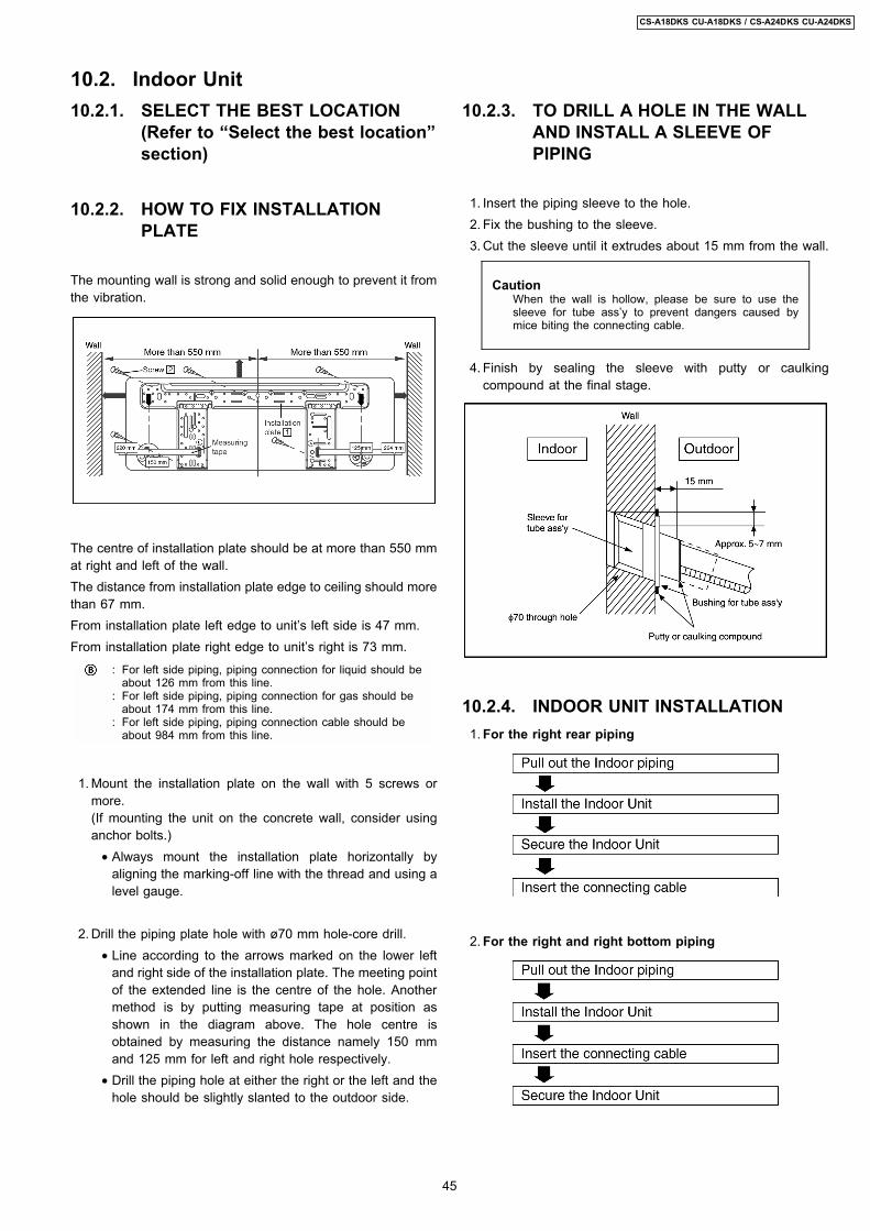
10.2.3. TO DRILL A HOLE IN THE WALLAND INSTALL A SLEEVE OFPIPING
1. Insert the piping sleeve to the hole. 2. Fix the bushing to the sleeve. 3. Cut the sleeve until it extrudes about 15 mm from the wall.
CautionWhen the wall is hollow, please be sure to use thesleeve for tube assy to prevent dangers caused bymice biting the connecting cable.
4. Finish by sealing the sleeve with putty or caulkingcompound at the final stage.
10.2.4. INDOOR UNIT INSTALLATION 1. For the right rear piping
2. For the right and right bottom piping
10.2. Indoor Unit
45
CS-A18DKS CU-A18DKS / CS-A24DKS CU-A24DKS

3. For the embedded piping
46
CS-A18DKS CU-A18DKS / CS-A24DKS CU-A24DKS

1. The inside and outside connecting cable can be connectedwithout removing the front grille.
2. Connecting cable between indoor unit and outdoor unitshall be approved polychloroprene sheathed 3 × 2.5 mm2
(C24DK) or 5 × 2.5 mm2 (A18DK, A24DK) flexible cord,type designation 245 IEC 57 or heavier cord. • Ensure the colour of wires of outdoor unit and the
terminal Nos. are the same to the indoors respectively. • Earth lead wire shall be longer than the other lead wires
as shown in the figure for the electrical safety in case ofthe slipping out of the cord from the anchorage.
• Secure the cable onto the control board with the holder(clamper).
INSTALLATION OF SUPER ALLERU-BUSTER FILTER
1. Open the front panel. 2. Remove the air filter. 3. Remove Supersonic air purifying device. 4. Open the Supersonic air purifying device frame. 5. Insert the super alleru-buster filter and close the Supersonic
air purifying device frame as shown in illustration at right.
10.2.5. CONNECT THE CABLE TO THE INDOOR UNIT
47
CS-A18DKS CU-A18DKS / CS-A24DKS CU-A24DKS

HOW TO TAKE OUT FRONT GRILLE
Please follow the steps below to take out front grille ifnecessary such as when servicing. 1. Open the intake grille. 2. Set the vertical airflow direction louvers to the horizontal
position. 3. Slide down the 3 caps on the front grille as shown in the
illustration below, and then remove the 3 mounting screws. 4. Pull the lower section of the front grille towards you to
remove the front grille.
When reinstalling the front grille, first set the verticalairflow direction louvers to the horizontal position andthen carry out above steps 2 - 3 in the reverse order.
AUTO SWITCH OPERATION
The below operations will be performed by pressing theAUTO switch. 1. AUTO OPERATION MODE
The Auto operation will be activated immediately once theAuto Switch is pressed.
2. TEST RUN OPERATION (FOR PUMP DOWN/SERVICINGPURPOSE)The Test Run operation will be activated if the Auto Switchis pressed continuously for more than 5 sec.. A beepsound will occur at the fifth sec., in order to identify thestarting of Test Run operation.
3. REMOTE CONTROLLER RECEIVING SOUND ON/OFFThe ON/OFF of remote controller receiving sound can bechanged over by the following steps: a. Release the Auto Switch after Test Run operation is
activated. b. Then, within 20 sec. after (a), press Auto Switch for
more than 5 sec.A beep beep sound will occur at the fifth sec., thenrelease the Auto switch.
c. Within 20 sec. after (b), press Auto Switch again.Everytime Auto Switch is pressed (within 20 sec.interval), remote controller receiving sound status will bereversed between ON and OFF.Long beep sound indicates that remote controllerreceiving sound is OFF.Short beep sound indicates that remote controllerreceiving sound is ON.
48
CS-A18DKS CU-A18DKS / CS-A24DKS CU-A24DKS

• After selecting the best location, start installation accordingto Indoor/Outdoor Unit Installation Diagram.
1. Fix the unit on concrete or rigid frame firmly and horizontallyby bolt nut. (ø10 mm).
2. When installing at roof, please consider strong wind andearthquake. Please fasten the installation stand firmly withbolt or nails.
10.3.3. CONNECTING THE PIPINGConnecting The Piping To Indoor UnitPlease make flare after inserting flare nut (locate at joint portionof tube assembly) onto the copper pipe. (in case of using longpiping)Connect the piping • Align the center of piping and sufficiently tighten the flare
nut with fingers. • Further tighten the flare nut with torque wrench in specified
torque as stated in the table.
CUTTING AND FLARING THE PIPING 1. Please cut using pipe cutter and then remove the burrs. 2. Remove the burrs by using reamer. If burrs is not
removed, gas leakage may be caused.Turn the piping end down to avoid the metal powderentering the pipe.
3. Please make flare after inserting the flare nut onto thecopper pipes.
MODEL Piping size (Torque)Gas Liquid
A18DK 1/2 (55 N.m) 1/4 (18 N.m)C24DK, A24DK 5/8 (65 N.m) 1/4 (18 N.m)
10.3. Outdoor Unit10.3.1. SELECT THE BEST LOCATION
(Refer to Select the best location section)
10.3.2. INSTALL THE OUTDOOR UNIT
Connecting The Piping To Outdoor UnitDecide piping length and then cut by using pipe cutter. Remove burrs from cut edge. Make flare after inserting the flare nut(located at valve) onto the copper pipe.Align center of piping to valves and then tighten with torque wrench to the specified torque as stated in the table.
49
CS-A18DKS CU-A18DKS / CS-A24DKS CU-A24DKS

1. Connect a charging hose with a push pin to the Low sideof a charging set and the service port of the 3-way valve. • Be sure to connect the end of the charging hose with
the push pin to the service port. 2. Connect the center hose of the charging set to a
vacuum pump with check valve, or vacuum pump andvacuum pump adaptor.
3. Turn on the power switch of the vacuum pump andmake sure that the needle in the gauge moves from 0cmHg (0 Mpa) to -76 cmHg (-0.1 Mpa). Then evacuatethe air approximately ten minutes.
4. Close the Low side valve of the charging set and turn offthe vacuum pump. Make sure that the needle in thegauge does not move after approximately five minutes.
Note : BE SURE TO FOLLOW THIS PROCEDURE INORDER TO AVOID REFRIGERANT GAS LEAKAGE.
5. Disconnect the charging hose from the vacuum pumpand from the service port of the 3-way valve.
6. Tighten the service port caps of the 3-way valve at atorque of 18 N.m with a torque wrench.
7. Remove the valve caps of both of the 2-way valve and3-way valve. Position both of the valves to OPENusing a hexagonal wrench (4 mm).
8. Mount valve caps onto the 2-way valve and the 3-wayvalve. • Be sure to check for gas leakage.
10.3.4. EVACUATION OF THE EQUIPMENT
CAUTION • If gauge needle does not move from 0 cmHg (0 Mpa) to -76 cmHg (-0.1 Mpa), in step above take the following measure.-
• If the leak stops when the piping connections are tightened further, continue working from step .
• If the leak does not stop when the connections are retightened, repair the location of leak.
• Do not release refrigerant during piping work for installation and reinstallation. Take care of the liquid refrigerant , it may cause frostbite.
10.3.5. CONNECT THE CABLE TO THE OUTDOOR UNIT 1. Remove the control board cover from the unit by loosening the screw. 2. Connecting cable between indoor unit and outdoor unit shall be approved polychloroprene sheathed 3 × 2.5 mm2 (C24DK) or
5 × 2.5 mm2 ( A18DK, A24DK) flexible cord, type designation 245 IEC 57 or heavier cord.
3. Secure the cable onto the control board with the holder (clamper). 4. Attach the control board cover to the original position with the screw.
50
CS-A18DKS CU-A18DKS / CS-A24DKS CU-A24DKS

DISPOSAL OF OUTDOOR UNIT DRAIN WATER
• If a drain elbow is used, the unit should be placed on astand which is taller than 3 cm.
• If the unit is used in an area where temperature falls below0°C for 2 or 3 days in succession, it is recommended not touse a drain elbow, for the drain water freezes and the fanwill not rotate.
CHECK THE DRAINAGE
• Open front panel and remove air filters.(Drainage checking can be carried out without removing thefront grille.)
• Pour a glass of water into the drain tray-styrofoam. • Ensure that water flows out from drain hose of the indoor
unit.
EVALUATION OF THE PERFORMANCE
• Operate the unit at cooling operation mode for fifteenminutes or more.
• Measure the temperature of the intake and discharge air. • Ensure the difference between the intake temperature and
the discharge is more than 8°C.
NOTE:These equipment shall be connected to a suitable mains networkwith a main impedance less than the following:
CS/CU-C24DKD:0.13 Ω CS/CU-A24DKD:0.06 Ω
CHECK ITEMS
Is there any gas leakage at flare nut connections?Has the heat insulation been carried out at flare nutconnection?Is the connecting cable being fixed to terminal board firmly?Is the connecting cable being clamped firmly?Is the drainage OK?(Refer to Check the drainage section)Is the earth wire connection properly done?Is the indoor unit properly hooked to the installation plate?Is the power supply voltage complied with rated value?Is there any abnormal sound?Is the cooling operation normal?Is the thermostat operation normal?Is the remote controls LCD operation normal?Is the super alleru-buster filter is installed?
10.3.6. PIPE INSULATION 1. Please carry out insulation at pipe connection portion as mentioned in Indoor/Outdoor Unit Installation Diagram. Please wrap
the insulated piping end to prevent water from going inside the piping. 2. If drain hose or connecting piping is in the room (where dew may form), please increase the insulation by using POLY-E FOAM
with thickness 6 mm or above.
51
CS-A18DKS CU-A18DKS / CS-A24DKS CU-A24DKS

11 2-way, 3-way Valve2-way Valve (Liquid Side) 3-way Valve (Gas Side)
Works Shaft Position Shaft Position Service Port
Shipping Close Close Close(With valve cap) (With valve cap) (With cap)
Evacuation Close Close Open(Installation and (Counter-Clockwise) (Clockwise) (Push-pin)Re-installation)
Operation Open Open Close(With valve cap) (With valve cap) (With cap)
Pumping down Close Open Open(Transferring) (Clockwise) (Counter-Clockwise) (Connected manifold
gauge)
Evacuation Open Open Open(Servicing) With vacuum pump
Gas charging Open Open Open(Servicing) (With charging cylinder)
Pressure check Open(Servicing) Open Open (Connected manifold
gauge)
Gas releasing Open(Servicing) Open Open (Connected manifold
gauge)
52
CS-A18DKS CU-A18DKS / CS-A24DKS CU-A24DKS