10192 ESD 991 Overhead Air Ionizer - Farnell element14 · With the ionizer in place, insert the...
13
3 Overhead Air Ionizer 991 Instructions November 2006 78-9100-1135-8
Transcript of 10192 ESD 991 Overhead Air Ionizer - Farnell element14 · With the ionizer in place, insert the...

3Overhead Air Ionizer 991
Instructions
November 200678-9100-1135-8

�
Table of Contents
Safety Information ......................................................................................................................3
1.0 Description .............................................................................................................................4
Overview .......................................................................................................................................4
Performance ..................................................................................................................................4
2.0 Installation .............................................................................................................................6
Supplied Parts ...............................................................................................................................6
Mounting .......................................................................................................................................6
Power Plug Connection .................................................................................................................7
Multiple Ionizers - Interconnection ..............................................................................................7
3.0 Operation ...............................................................................................................................8
Operation .......................................................................................................................................8
Fault Indicator ...............................................................................................................................8
Alarm Output Jack ........................................................................................................................8
4.0 Maintenance ..........................................................................................................................9
Cleaning Solution..........................................................................................................................9
Chassis Cleaning ...........................................................................................................................9
Air Filters Cleaning .......................................................................................................................9
Emitter Points Cleaning ..............................................................................................................10
Auto-Clean System Use ..............................................................................................................10
5.0 Specifications .......................................................................................................................11
Properties and Typical Values .....................................................................................................11
Dimensional Drawing .................................................................................................................12
6.0 Accessories ...........................................................................................................................12
7.0 Customer and Technical Service ........................................................................................12
�
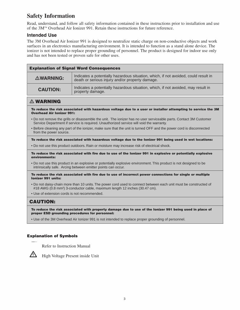
Safety InformationRead, understand, and follow all safety information contained in these instructions prior to installation and use of the 3M™ Overhead Air Ionizer 991. Retain these instructions for future reference.
Intended UseThe 3M Overhead Air Ionizer 991 is designed to neutralize static charge on non-conductive objects and work surfaces in an electronics manufacturing environment. It is intended to function as a stand alone device. The ionizer is not intended to replace proper grounding of personnel. The product is designed for indoor use only and has not been tested or proven safe for other uses.
Explanation of Signal Word Consequences
WARNING: Indicates a potentially hazardous situation, which, if not avoided, could result in death or serious injury and/or property damage.
CAUTION: Indicates a potentially hazardous situation, which, if not avoided, may result in property damage.
WARNINGTo reduce the risk associated with hazardous voltage due to a user or installer attempting to service the 3M Overhead Air Ionizer 991:
• Do not remove the grills or disassemble the unit. The ionizer has no user serviceable parts. Contact �M Customer Service Department if service is required. Unauthorized service will void the warranty.
• Before cleaning any part of the ionizer, make sure that the unit is turned OFF and the power cord is disconnected from the power source.
To reduce the risk associated with hazardous voltage due to the Ionizer 991 being used in wet locations:
• Do not use this product outdoors. Rain or moisture may increase risk of electrical shock.
To reduce the risk associated with fire due to use of the Ionizer 991 in explosive or potentially explosive environments:
• Do not use this product in an explosive or potentially explosive environment. This product is not designed to be intrinsically safe. Arcing between emitter points can occur.
To reduce the risk associated with fire due to use of incorrect power connections for single or multiple Ionizer 991 units:
• Do not daisy-chain more than 10 units. The power cord used to connect between each unit must be constructed of #18 AWG (0.8 mm²) �-conductor cable, maximum length 1� inches (�0.47 cm).
• Use of extension cords is not recommended.
CAUTION:To reduce the risk associated with property damage due to use of the Ionizer 991 being used in place of proper ESD grounding procedures for personnel:
• Use of the �M Overhead Air Ionizer 991 is not intended to replace proper grounding of personnel.
Explanation of Symbols
Refer to Instruction Manual
High Voltage Present inside Unit

4
1.0 Description
Overview
The 3M™ Overhead Air Ionizer 991 neutralizes static over bench top areas without occupying valuable work space. The Ionizer 991 operates with steady-state DC ion emission that provides fast discharge with low airflow. Emitter points are placed behind the fan to eliminate field-induced charge and to ensure a homogenous mixture of ionized air. The Ionizer 991 is available in the following configurations:
98-0798-568�-1 Overhead Air Ionizer 991 with North America Power Cord
98-0798-5684-9 Overhead Air Ionizer 991 with UK Power Cord
98-0798-5694-8 Overhead Air Ionizer 991 with Germany Power Cord
98-0798-5695-5 Overhead Air Ionizer 991 with China Power Cord
Features of the 3M Overhead Air Ionizer 991:
• Length: 44 inches (111.8 cm)
• Fans: 3
• Fan Speeds: High and low (switched high, low, & OFF)
• Protective Fan Filters: Open-cell foam filters on fan intakes protect the internal components from environmental contamination.
• Bi-Color Red/Green Indicator LED: Illuminates green when power is applied to the ionizer and the unit is turned to low or high fan speed; illuminates red when high voltage power supply failure has occurred.
• Auto-Clean System: Brush mechanism installed on each fan, sweeps the emitter points during start up and shut off operation of the ionizer. This feature reduces the frequency of required manual emitter point cleanings as outlined in Section 4.0 of this manual. During full operation of the fan, the brush retracts to
prevent wearing the emitter points.
Performance
Discharge time tests indicate less than or equal to 8 seconds (1000V to 100V) directly under each of the fans.
Note: Testing performed with the unit mounted 24 inches above the work surface and fans at high speed using a charged plate monitor in accordance with the ESD Association Ionization Standard ESD STM3.1-2000.
In a constant temperature/humidity environment, the 3M Overhead Air Ionizer 991 will maintain a balance of less than or equal to ±20V.
There is a direct relationship between the distance the unit is installed from the work surface, the area of coverage, and the discharge time measured at the work surface. Generally, the greater the mounting distance from the work surface, the greater the area of coverage will be, and the longer the discharge time will be (Fig. 1 & Table 1).
The unit's internal emitter points are electrostatically shielded to eliminate field-induced charging. Steady-state DC ion emission provides fast discharge with low airflow for greater operator comfort. The ionizer never needs calibration and requires very little maintenance. The technology is based on a law of physics, Conservation of Charge, which states that charge cannot be created or destroyed in an isolated system. By isolating the ionizer’s emitter points from ground, it ensures equal numbers of positive and negative ions.

5
Fig. 1 - Test Locations
Test PointFan SpeedH = HighL = Low
+ Decay RateSeconds
Decay RateSeconds
Offset Voltage
Volts
#1H �1.8 �7.5 -1L �6.1 �7.8 -1
#�H 6.9 6.7 8.5L 8.7 9.4 5
#�H 14.5 17.� 0L ��.� �8.1 0
#4H 6.� 7.� 1L 8.6 11.4 1
#5H �.4 �.5 1�L 4.6 5.0 8.5
#6H 6.� 8.0 -1L 10.� 1�.0 -1
#7H 6.� 7.� -1L 9.� 10.8 -1
#8H �.7 �.9 11L 5.0 5.4 7
#9H 9.6 11.6 0L 1�.7 15.8 -1
#10H 10.� 10.8 �L 17.� 17.4 1
#11H 6.8 7.6 6L 10.1 10.6 �.5
#1�H 51.� 71.6 -1.5L 66.9 80.9 -1
Table 1 - �M™ Overhead Air Ionizer 991 Performance Typical Values (At 75° F, 50% RH)
16 in. 16 in.16 in.
12 in.
12 in.
6
2.0 Installation
Supplied Parts
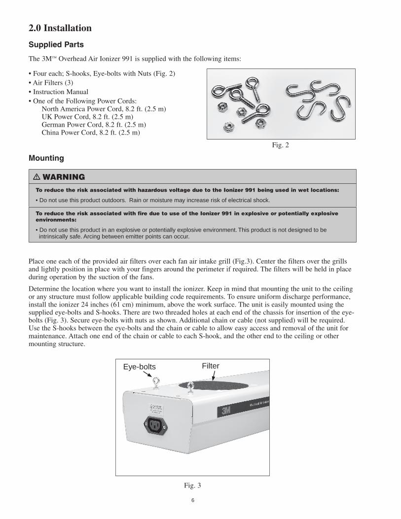
The 3M™ Overhead Air Ionizer 991 is supplied with the following items:
• Four each; S-hooks, Eye-bolts with Nuts (Fig. 2)• Air Filters (3) • Instruction Manual• One of the Following Power Cords: North America Power Cord, 8.2 ft. (2.5 m) UK Power Cord, 8.2 ft. (2.5 m) German Power Cord, 8.2 ft. (2.5 m) China Power Cord, 8.2 ft. (2.5 m)
Fig. 2
Mounting
WARNINGTo reduce the risk associated with hazardous voltage due to the Ionizer 991 being used in wet locations:
• Do not use this product outdoors. Rain or moisture may increase risk of electrical shock.
To reduce the risk associated with fire due to use of the Ionizer 991 in explosive or potentially explosive environments:
• Do not use this product in an explosive or potentially explosive environment. This product is not designed to be intrinsically safe. Arcing between emitter points can occur.
Place one each of the provided air filters over each fan air intake grill (Fig.3). Center the filters over the grills and lightly position in place with your fingers around the perimeter if required. The filters will be held in place during operation by the suction of the fans.
Determine the location where you want to install the ionizer. Keep in mind that mounting the unit to the ceiling or any structure must follow applicable building code requirements. To ensure uniform discharge performance, install the ionizer 24 inches (61 cm) minimum, above the work surface. The unit is easily mounted using the supplied eye-bolts and S-hooks. There are two threaded holes at each end of the chassis for insertion of the eye-bolts (Fig. 3). Secure eye-bolts with nuts as shown. Additional chain or cable (not supplied) will be required. Use the S-hooks between the eye-bolts and the chain or cable to allow easy access and removal of the unit for maintenance. Attach one end of the chain or cable to each S-hook, and the other end to the ceiling or other mounting structure.
Fig. 3
Eye-bolts Filter

7
Power Plug Connection
WARNINGTo reduce the risk associated with fire due to use of incorrect power connections for single or multiple 3M™ Overhead Air Ionizer 991 units:
• Use of extension cords is not recommended.
With the ionizer in place, insert the female end of the supplied AC cord into the male IEC power plug connector located at one end of the unit (Fig. 4). Insert the male end of the AC cord into a properly grounded 100 - 230 VAC 50/60 Hz receptacle.
Note: If a grounded AC outlet is not located near the ionizer, an outlet should be installed following all applicable building and National Electrical Code requirements.
Fig. 4
Multiple Ionizers - Interconnection
WARNINGTo reduce the risk associated with fire due to use of incorrect power connections for single or multiple Ionizer 991 units:
• Do not daisy-chain more than 10 units. The power cord used to connect between each unit must be constructed of #18 AWG (0.8 mm²) �-conductor cable, maximum length 1� inches (�0.47 cm).
• Use of extension cords is not recommended.
Several ionizers can be connected together in a series (called daisy-chaining), using the female AC outlet socket (IEC60320) provided on the opposite end of the power input to the unit (Fig. 5). This outlet is unfused and has a maximum rating of 5A. The maximum recommended number of 3M Overhead Air Ionizers that can be daisy-chained is 10 units. Each ionizer has a current rating of 0.4A. The power cord used to connect between each unit should be constructed of #18 AWG (0.8 mm²) 3-conductor cable. The maximum connecting power cord length is 12 inches (30.48 cm) between each unit.
Fig. 5

8
3.0 Operation
CAUTION:To reduce the risk associated with property damage due to use of the 3M™ Overhead Air Ionizer 991 being used in place of proper ESD grounding procedures for personnel:
• Use of the Ionizer 991 is not intended to replace proper grounding of personnel.
Operation
Use the power/fan speed slide switch located on the end of the ionizer to turn the unit ON (Fig. 4). When the ionizer is ON, the bi-color LED located on the bottom of the unit should illuminate green and all fans will rotate.
Fault Indicator
In the event of a fault condition, the bi-color LED will change to illuminate red. A fault condition indicates that the unit’s internal high voltage power circuitry is not functioning correctly. Causes may include:
• Low or incorrect input voltage• An internal part has been compromised
In most cases the red condition is indicating that service will be required. However, before contacting 3M Customer Service Department for service, check for the following if the LED is illuminated red:
Check For Action
Dirty emitter points Clean emitter points
Incorrect input voltage or failures, shorts, or obstructions to power cables.
Ensure the ionizer has proper input voltage.
Alarm Output Jack
The 3M Overhead Air Ionizer 991 can be connected to a remote alarm indicator or monitor by using the modular output jack located on the end of the unit (Fig. 4). When a fault condition is detected, the internal relay contacts will change states as indicated in the diagram (Fig. 6) below. The relay can be interfaced to a user supplied alarm monitoring device or audible alarm. The output jack is rated for a maximum current of 1.0 amp and 30 volts.
Fig. 6

9
4.0 Maintenance
WARNINGTo reduce the risk associated with hazardous voltage due to a user or installer attempting to service the 3M™ Overhead Air Ionizer 991:
• Do not remove the grills or disassemble the unit. The ionizer has no user serviceable parts. Contact �M Customer Service Department if service is required. Unauthorized service will void the warranty.
• Before cleaning any part of the ionizer, make sure that the unit is turned OFF and the power cord is disconnected from the power source.
To reduce the risk associated with fire due to improper cleaning or incorrect connection of multiple units:
• Do not use this product in an explosive or potentially explosive environment. Arcing between emitter points can occur during operation if contamination is allowed to build up. Follow periodic cleaning instructions carefully.
• Do not daisy-chain more than 10 units. The power cord used to connect between each unit must be constructed of #18 AWG (0.8 mm²) �-conductor cable, maximum length 1� inches (�0.47 cm).
Cleaning Solution
Required Cleaning Materials:
• Solution of 50% Deionized Water and 50% Isopropanol (IPA)
• Clean Room-approved Swab (foam is not recommended)
• Clean Room-compatible Wipe
Chassis Cleaning
Moisten a cloth with IPA solution. Wipe off any dirt that may have accumulated on the surface of the chassis. Change the cloth frequently to ensure that the dirt is being completely removed from the chassis.
Note: Use only the recommended diluted IPA solution to clean the chassis. Do not use any cleaners or solvents that may damage the powder coat finish of the chassis.
Air Filters Cleaning
Eventually, air filters may become dirty or deteriorate. Maintenance schedule will be determined by environmental conditions.
To wash or replace the filters:
1. Switch OFF power to the ionizer. The foam filters will then loosen for removal (Fig. 7).
2. Remove the filters from the top of the chassis. Wash the filters in warm water and mild detergent solution. Rinse filters with clean warm water until all detergent is removed.
3. Dry the filters completely.
Note: Filter must be dry before re-installing them on the intake grills of the fans.
4. To re-install the filters, place and center the filters over the grills. Lightly position the filter with your fingers around the perimeter if required. The filter will be held in place during operation by the suction of the fans.
Note: Replacement filters are available (Section 6.0 Accessories).
Fig. 7
10
Emitter Points Cleaning
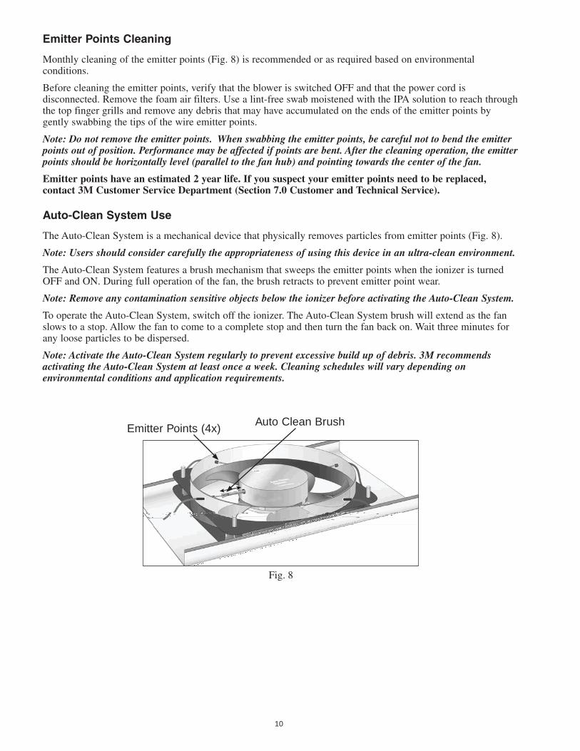
Monthly cleaning of the emitter points (Fig. 8) is recommended or as required based on environmental conditions.
Before cleaning the emitter points, verify that the blower is switched OFF and that the power cord is disconnected. Remove the foam air filters. Use a lint-free swab moistened with the IPA solution to reach through the top finger grills and remove any debris that may have accumulated on the ends of the emitter points by gently swabbing the tips of the wire emitter points.
Note: Do not remove the emitter points. When swabbing the emitter points, be careful not to bend the emitter points out of position. Performance may be affected if points are bent. After the cleaning operation, the emitter points should be horizontally level (parallel to the fan hub) and pointing towards the center of the fan.
Emitter points have an estimated 2 year life. If you suspect your emitter points need to be replaced, contact 3M Customer Service Department (Section 7.0 Customer and Technical Service).
Auto-Clean System Use
The Auto-Clean System is a mechanical device that physically removes particles from emitter points (Fig. 8).
Note: Users should consider carefully the appropriateness of using this device in an ultra-clean environment.
The Auto-Clean System features a brush mechanism that sweeps the emitter points when the ionizer is turned OFF and ON. During full operation of the fan, the brush retracts to prevent emitter point wear.
Note: Remove any contamination sensitive objects below the ionizer before activating the Auto-Clean System.
To operate the Auto-Clean System, switch off the ionizer. The Auto-Clean System brush will extend as the fan slows to a stop. Allow the fan to come to a complete stop and then turn the fan back on. Wait three minutes for any loose particles to be dispersed.
Note: Activate the Auto-Clean System regularly to prevent excessive build up of debris. 3M recommends activating the Auto-Clean System at least once a week. Cleaning schedules will vary depending on environmental conditions and application requirements.
Fig. 8
Emitter Points (4x)Auto Clean Brush

11
5.0 Specifications
Property Typical ValuesIon Emission Steady state (DC)
Emitter Points 0.1� in. (�.048 mm) tungsten wire, internally shielded, � year life estimated
Air Flow 114 CFM (per fan, high speed, free-air)
Audible Noise 6� dB, high fan speed
57 dB, low fan speed
Power Inlet IEC60��0 (with removable line cord)
Input Voltage 100-��0 VAC, 50/60 Hz, �7 watts max.
Input Current 0.4A max.
Power �7W max.
Discharge Time ≤ 8 seconds directly under each fan at 18 in. (46 cm) distance, high fan speed
Offset Voltage Balance ≤ ±�0 volts directly under each fan at 18 in. (46 cm) distance; high fan speed
Power Outlet IEC60��0 female, unfused, 5A maximum load
Alarm Relay Closure Modular handset jack, rated 1A maximum, �0 volts
Coverage Area � ft. x 4 ft. (61 cm x 1�� cm) directly under ionizer
Controls Power/fan speed slide switch: high/off/low settings
Indicators Bi-color LED: green power ON; red power supply failure
Daisy-Chain Capacity 10 units maximum
Chassis Aluminum with epoxy-polyester powder coated
Mounting Four eyebolts and 1 1/8 in. S-hooks provided
Dimensions 44 in. L x 6 in. W x 4 in. H
(111.7 cm L x 15.� cm W x 10.1 cm H)
Operating Environment Temperature: 50°-95° F (10°-�5° C)
Humidity: �0-55% RH (non-condensing)
Ozone Level < 0.010 ppm
RoHS Compliant Yes
Weight 10 lb (4.5 kg)
Certifications cULus, TUV-GS, CE, C-Tick
Warranty 1 year limited

1�
Dimensional Drawing (For Reference Only)
6.0 Accessories3M™ Replacement Filters 991-F, 3 Filters/Pkg., 3M ID #: 98-0798-5696-3
7.0 Customer and Technical ServiceFor customer service and technical support within the US:Contact 3M Electronic Solutions Division, Customer Service Department 800-328-1368.
For customer service and technical support outside the US:Contact your local representative of the 3M Electronic Solutions Division

Important Notice
All statements, technical information, and recommendations related to 3M’s products are based on information believed to be reliable, but the accuracy or completeness is not guaranteed. Before using this product, you must evaluate it and determine if it is suitable for your intended application. You assume all risks and liability associated with such use. Any statements related to the product which are not contained in 3M’s current publications, or any contrary statements contained on your purchase order shall have no force or effect unless expressly agreed upon, in writing, by an authorized officer of 3M.
Warranty; Limited Remedy; Limited Liability. This product will be free from defects in material and manufacture for a period of one year from the time of purchase. 3M MAKES NO OTHER WARRANTIES INCLUDING, BUT NOT LIMITED TO, ANY IMPLIED WARRANTY OF MERCHANTABILITY OR FITNESS FOR A PARTICULAR PURPOSE. If this product is defective within the warranty period stated above, your exclusive remedy shall be, at 3M’s option, to replace or repair the 3M product or refund the purchase price of the 3M product. Except where prohibited by law, 3M will not be liable for any indirect, special, incidental or consequential loss or damage arising from this 3M product, regardless of the legal theory asserted.
33M Electronics6801 River Place Blvd. Austin, TX 78726-9000 800/328-1368www.3M.com/electronics
Litho in USA© 3M 2006 78-9100-1135-8
�M is a trademark of �M Company. Other trademarks used herein are the properties of their respective owners.
Please recycle