Browning/USEM Otn Helical Bevel Right Angle Gearmotors/Reducers
204
Transcript of Browning/USEM Otn Helical Bevel Right Angle Gearmotors/Reducers


The Emerson logo is a trademark and a service mark of Emerson Electric Co.
© Emerson Power Transmission Manufacturing, L. P. or affiliates 2007. All rights reserved.

B-1
OtN SeriesComplete Gearing Solutions...
Sta
nd
ard
So
luti
on
s Emerson Power TransmissionHas the Industry’s BroadestLine of Standard Gearmotorsand Speed Reducers
CbN InlineConcentric Gearmotor
COBRA™Worm Gear Reducer
Motorized Conveyor Pulley
Power-Match PlusPoweRgear®
Worm GearReducer
MbN HelicalShaft MountGearmotor
Helical Parallel ShaftGear Reducer
Shaft MountSpeed Reducer
TORQ TAPER® Plus
Raider®
Worm Gear Reducer

B-2
OtN Series
OtN Helical BevelRight Angle
Gearmotors andSpeed Reducers
C-Face
Gearmotor
Top Mount
Scoop Mount
Input Shaft

B-3
Gearmotors and Reducers 20003000
SERIESOtN
OtN Series
Reducer Section...................................... Page B-102 - B-187
Gearmotor Section...................................... Page B-5 - B-101

20003000
SERIESOtN
B-4
OtN Series
Gearmotors and Reducers
Mounting Versatility and Size Range
Foot MountFrames 2-8Solid Shaft
Max. 88,000 lb-in
NEMA C-Face56C to 326TC
Input Shaft
Top MountFrames 3 - 5**
56 to 256T
Scoop MountFrames 3 - 8*
56 to 326T
C-Face MotorsFrames 56C - 326TC
Gearmotors1/6 - 75 HP
Variable SpeedIntelliGear®
1/3 - 10 HP
Backstop Options ***
Shaft MountTorque ArmFrames 2-8Hollow Shaft
Tapered Bushed (Fr 2 - 5)Max. 88,000 lb-in
Face MountFrames 2-8Hollow Shaft
Max. 88,000 lb-in
Flange MountFrames 2-8Solid Shaft
Hollow ShaftMax. 88,000 lb-in
High Ratio CombinedFrames 2-8 - All Styles
Max. 88,000 lb-in
* Not available for frames 2 - 5, 5-stage or frames 4 - 6, 6-stage.** Only available for frames 3 - 5, 3-stage.***Not available for frames 3245 and 3365A. Available input shaft or scoop mount only for frames 6 - 8.
Modular TaperedConnection48 - 365T

B-5
20003000
SERIESOtN
OtN Series
Type OtN Helical BevelSeries 2000/3000 Gearmotor Features...
Design Features1. Innovative Self-Locking, Self-Aligning Taper Shaft Motor Connection
• Easy on-site motor replacement.• Change motor without draining oil, breaking the gearcase seal, or changing primary pinion.• Eliminates fretting, ensures precision alignment and solid connection for indexing.
2. Gearbox Supplied Factory Filled with Synthetic Oil• Wide temperature range and longer life.
3. Corrosion and Shock Resistant Cast Iron Housing• One piece, reinforced and ribbed for extra strength.
4. Gears and Shafts of Nickel Chromium Molybdenum Steel• Helical gearing is case hardened and then skived, superfinished or ground.• All gears heat shrunk on shafts or mounted on self-locking tapered shafts and keyed for high shock load
capability.
5. Normally Closed Breather with Multiple Locations (Optional OtN2000)
6. Double Lip Seals on Heat Treated, Plunge Ground Shafts
7. Magnetic Drain Plug Standard
5
4
61
2
3
Gearmotors
7

20003000
SERIESOtN
B-6
OtN Series
Table of Contents
Section PageGeneral Information ......................................................................................................................................... B-7Mounting Versatility and Size Range ............................................................................................................... B-8Motor Options .................................................................................................................................................. B-9Gearmotor Selection (constant speed) ............................................................................................... B-10 - B-11Gearmotor Selection (IntelliGear) ....................................................................................................... B-12 - B-13Catalog Nomenclature ........................................................................................................................ B-14 - B-15Gearmotor Mounting Positions ...................................................................................................................... B-16Gearmotor Output Brackets and Shafts ........................................................................................................ B-17Electrical Connection Options ....................................................................................................................... B-18Modifications, Options and Accessories ............................................................................................. B-19 - B-21Torque Reaction Arms ........................................................................................................................ B-22 - B-23Tapered Bushing Selections .......................................................................................................................... B-24AGMA Application Classifications....................................................................................................... B-25 - B-27Gearmotor Selection Tables ............................................................................................................... B-28 - B-62Dimension Prints with Standard TEFC Motors
Output Shafted Foot Mount .......................................................................................................... B-64 - B-69Output Shafted Flange Mount ...................................................................................................... B-70 - B-75Finished Bore Hollow Shaft .......................................................................................................... B-76 - B-81Finished Bore Hollow Shaft Face Mount ...................................................................................... B-82 - B-87Finished Bore Hollow Shaft Flange Mount ................................................................................... B-88 - B-93Taper Bushed Shaft Mount ........................................................................................................... B-94 - B-97Alternate Motor End Dimension ................................................................................................... B-98 - B-99Type "T" & "S" Motor Brake Dimensional Supplement .......................................................................... B-100
Gearmotor Weights ...................................................................................................................................... B-101Lubrication ................................................................................................................................................... B-187Gearmotor - Typical Motor Performance Data ........................................................................................ E-1 - E-4IntelliGear Technical Specifications ........................................................................................................ E-5 - E-9NEMA Standard Dimensions ......................................................................................................................... E-10General Information ....................................................................................................................................... E-11Standard Terms and Conditions of Sale ........................................................................................................ E-12
Gearmotors

B-7
20003000
SERIESOtN
OtN Series
GeneralOtN helical-bevel right angle gearmotors and speedreducers incorporate the latest in design andmanufacturing technologies to deliver an energyefficient, reliable, helical-bevel gear train. This gearingcan be combined with either a constant or variablespeed motor if a gearmotor is desired. The latestgeneration of OtN gearing is 98% efficient per gearstage, with three, five or six stages available for ratiosof 10:1 to 10,000:1. OtN is available in a wide variety ofmounting arrangements that include foot mount, facemount, flange mount or shaft mount with a torque arm.The output can be left, right, or dual solid shaft or shaftmounted with hollow quill or new tapered bushed.
HousingThe unique housing design allows the OtN3000 todirectly interchange with many popular competitiveproducts, while offering a version that also replaces theOtN2000 sizes that it replaces. This allows for simpleaftermarket replacement of both OtN2000 and many ofthe more common helical-bevel products from othermanufacturers. All housings are cast from high-strengthcast iron. Additionally, the new, quill style c-face ofOtN3000 is often shorter than competitive designs, whileallowing room for a fully rated backstop.
PerformanceOtN designs deliver ratings that are amongst the highestin the industry for similar frame sizes. For replacements,this means that dimensional replacements generallymeet or exceed the original unit ratings for long life. Innew applications, this can mean cost savings throughdownsizing versus the competition. Each OtN unit isalso supplied factory-filled with high quality syntheticlubricant, an extra cost option for competitive units. Thisoffers operation over a wide temperature range withminimal maintenance required.
FlexibilityThe new OtN3000 offers a shaft-mounted version thatincorporates the tapered bushing system from theBrowning® Torque Taper Plus® shaft mount reducer. Thisextends each frame size to be usable on a variety ofshaft sizes. It also provides a proven bushing systemwith a centering ring that reduces wobbling on the shaftfor reduced wear and tear. All sizes are also availablewith a hollow quill sized to match popular competitiveunits. The bushed version of OtN3000 includes abushing to match the OtN2000 equivalent frame sizefor replacements. The shaft-mounted units all includefeet on the housing base and they can be tied down tothe machine frame using a face mount, flange mount,or torque arm. There are two flanges available in eachOtN3000 frame size, one of which is competitivelyinterchangeable. Also, for applications requiring thegearmotors to be powered by an inverter (VFD), all threephase motor designs now incorporate an upgraded wireand varnish treatment called Allguard. Housings canbe mounted in a variety of positions as well, with only achange in the breather and drain plug positions and achange in oil volume.
GearmotorsThe industry’s most diverse array of different motorconstructions and voltages in three and single phaseare stocked to meet most industry and userspecifications. This now includes IntelliGear variablespeed TEFC gearmotors that incorporate a rugged,compact, pre-programmed AC variable frequencydrive onboard for simple 6:1, 10:1, or 15:1 constanttorque speed ranges. Emerson Power Transmissionexclusive offerings are the inverter duty gearmotorsthat are fully compliant with NEMA MG1 Part 31 andthe explosion proof gearmotors.
ReliabilityGear housing sizes 2-5 are fitted with normally closedbreathers to exclude contaminants, while preservinglow internal operating pressure. All oil seals operateon plunge ground shaft surfaces to deliver extendedlife. Enhanced insulating materials and otherstandard features of our premium Varidyne inverterduty motors allow Emerson Power Transmission toextend an industry leading 3-year motor warranty,even when using these motors with PWM inverterpower up to 575 VAC.
Gearmotors
General Information
20003000
SERIESOtN
B-8
OtN Series
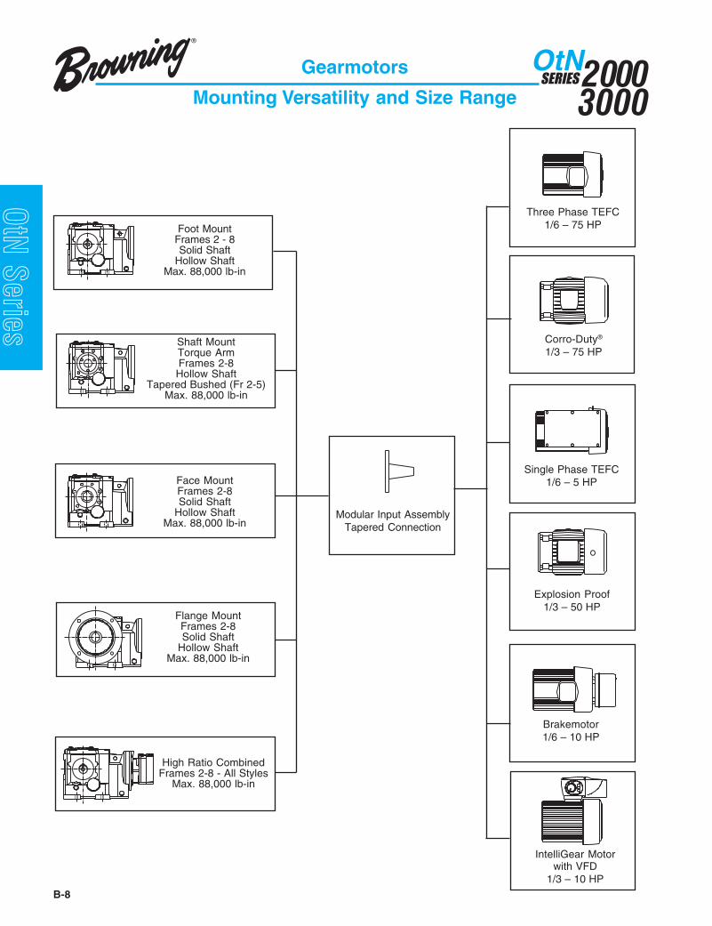
Three Phase TEFC1/6 – 75 HP
Corro-Duty®
1/3 – 75 HP
Brakemotor1/6 – 10 HP
Explosion Proof1/3 – 50 HP
Modular Input AssemblyTapered Connection
Single Phase TEFC1/6 – 5 HP
Gearmotors
Mounting Versatility and Size Range
Foot MountFrames 2 - 8Solid Shaft
Hollow ShaftMax. 88,000 lb-in
Shaft MountTorque ArmFrames 2-8Hollow Shaft
Tapered Bushed (Fr 2-5)Max. 88,000 lb-in
Face MountFrames 2-8Solid Shaft
Hollow ShaftMax. 88,000 lb-in
Flange MountFrames 2-8Solid Shaft
Hollow ShaftMax. 88,000 lb-in
High Ratio CombinedFrames 2-8 - All Styles
Max. 88,000 lb-in
IntelliGear Motorwith VFD
1/3 – 10 HP
B-9
20003000
SERIESOtN
OtN Series
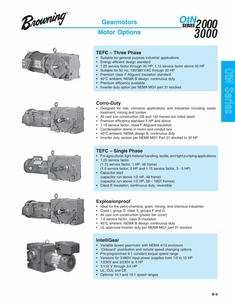
TEFC – Three Phase• Suitable for general purpose industrial applications• Energy efficient design standard• 1.25 service factor through 30 HP; 1.15 service factor above 30 HP• Suitable for 50 Hz, 190/380 VAC through 30 HP• Premium class F Allguard insulation standard• 40°C ambient, NEMA B design, continuous duty• Premium efficiency available• Inverter duty option per NEMA MG1 part 31 stocked
Corro-Duty• Designed for wet, corrosive applications and industries including waste
treatment, mining and lumber.• All cast iron construction (56 and 140 frames are rolled steel)• Premium efficiency standard 3 HP and above• 1.15 service factor, class F Allguard insulation• Condensation drains in motor and conduit box• 40°C ambient, NEMA design B, continuous duty• Inverter duty version per NEMA MG1 Part 31 stocked to 20 HP
TEFC – Single Phase• For agricultural, light material handling, textile, and light pumping applications• 1.25 service factor
(1.15 service factor, 1 HP, 48 frame)(1.0 service factor, 2 HP and 1.15 service factor, 3 - 5 HP)
• Capacitor start(capacitor run above 1/2 HP, 48 frame)(capacitor run above 1/2 HP, 56 – 180T frames)
• Class B insulation, continuous duty, reversible
Explosionproof• Ideal for the petro-chemical, grain, mining, and chemical industries• Class I, group D, class II, groups F and G• All cast iron construction (plastic fan cover)• 1.0 service factor, class B insulation• 40°C ambient, NEMA B design, continuous duty• UL approved Inverter duty per NEMA MG1 part 31 stocked
IntelliGear• Variable speed gearmotor with NEMA 4/12 enclosure• "Onboard" pushbutton and remote speed changing options• Pre-programmed 6:1 constant torque speed range• Versions for 3/460V input power supplies from 1/3 to 10 HP• 1/230V and 3/230V to 5 HP• 1/115 V through 3/4 HP• UL, CUL and CE• Optional 10:1 and 15:1 speed ranges
Gearmotors
Motor Options

20003000
SERIESOtN
B-10
OtN Series
elcyCytuD sruoHnoitarepO
mrofinUdaoL
U
etaredoMkcohS
daoLM
yvaeHkcohS
daoLV
suounitnoC3-001-342-01
08.000.152.1
00.152.105.1
05.157.100.2
tneuqerF*spotS/stratS
3-001-342-01
00.152.105.1
52.105.157.1
57.100.252.2 rebmeMgnivirD KfoeulaV
evirDniahC 00.1noiniP 52.1tleB-V 05.1
stleBgnimiT 52.1
noitacoLdaoL FLLfoeulaVnoisnetxetfahsfodnE 02.1
noisnetxetfahsforetneC 00.1redluohsnoisnetxetfahS 08.0
Constant Speed
Gearmotor Selection
Step 1 -Locate gearmotor selection tables (pages B-28 - B-62)based on motor HP.
Step 2 -Choose the appropriate nominal speed or ratio required.
Step 3 -Select the correct gearmotor based on AGMA class orservice factor determined from selection information.
Step 4 - Verify overhung load ratings where required (see below).
When a sprocket, sheave, pulley, or pinion is mounted on thetake-off shaft of a gearmotor, it is necessary to calculate theoverhung load. This calculated load must be compared with thegearbox capacity listed to make sure the gearbox will not beoverloaded. To calculate the overhung load you need to know thetorque or horsepower at the take-off shaft and the location alongthe shaft at which the load is applied.
A. If torque is known:
OHL =
B. If horsepower is known:
OHL =
Where:OHL = Overhung load (pounds)T = Torque (in. lbs.)r = Radius of driving member (in.)HP = HorsepowerK = Drive type factorLLF = Load location factor
1. Input HP• Based on application data
2. Speed / ratio• Obtain either desired output speed (RPM) or gearbox ratio
based on application.
3. Mechanical service factors - gears• There are three standard classifications for gearmotor
applications:
Class I - uniform loading, 3-10 hours per day, service factor1.0 (minimum).
Class II - uniform loading over 10 hours per day ormoderate shock loading up to 10 hours per day; servicefactor 1.4 (minimum).
Class III - moderate shock loading over 10 hours per dayor heavy shock loading up to 10 hours per day; servicefactor 2.0 (minimum).
• The tables on pages B-25 through B-27 are based on pastoperating experience within the industries listed and infor-mation gathered by AGMA. If the user has data reflectinggreater severity than normal industry usage, then theAGMA class should be increased.
• Choose the AGMA class for your given application basedon this criteria. If your application cannot be found, use thefollowing table to determine the service factor.
Size SelectionSelection Information
Overhung Load
T x K x LLFr
63025 x HP x K x LLFRPM x r
*Greater than 10 per hour

B-11
20003000
SERIESOtN
OtN Series
Selection ExampleA right angle, foot mounted gearmotor is required to operate a uniformly loaded belt conveyor at 30 RPM, 24hours per day. An 11" diameter sprocket is mounted at the end of the shaft and drives the conveyor with a chaindrive. The customer has specified a standard 230/460 VAC, 3-phase, TEFC gearmotor rated 5 HP. Shaftextension is to be on the right, viewing the motor fan cover. The unit will be in the normal floor mounted positionwith the motor horizontal and the mounting feet on the bottom.
Refer to AGMA service classification table on page B-25.
Application Load ClassUp to 10 Over 10
Conveyors – Uniformly Loaded Hrs/Day Hrs/Dayor Fed: Apron, Assembly,Belt, Bucket, Chain, Flight,Oven, Screw U I II
Since this application operates 24 hours per day, a Class II service factor is required.
Step 1... Locate a gearmotor for 5 HP on page B-48.
Step 2... Find a nominal speed closest to the 30 RPM output required.
Step 3... Select the row in the table for Class II service factor.
Output AGMA Service Output Torque OHL Nominal Frame Size Std. Motorrpm Class Factor in-lb lb Ratio Gear Motor Types31 I,II 1.4 9661 2875 56 3473 184T T,C,S,X,IG28 I 1.3 10491 2875 63 3473 184T T,C,S,X,IG
30 rpm falls between these two lines in the selection table, but the 28 rpm line doesn't meet the Class II servicefactor requirement. Size 3473 gear frame with 56:1 nominal ratio and 31 rpm output is the best selection.
Step 4... Verify that the Overhung Load Rating is sufficient for the applied load.
r = Sprocket Diameter 11 = 5.5"2 2
K = 1.0 (chain drive)LLF = 1.2 (sprocket on end of shaft)HP = 5
OHL = 63025 x HP x K x LLF = 63025 x 5 x 1.0 x 1.2 = 2217.9 lbs.rpm x r 31 x 5.5
Since the gearmotor output OHL rating is 2875 lbs (see selection table) and this is greater than the applied OHL of2217.9 lbs, the selection is fine. If the OHL rating was too low, the sprocket diameter or gear frame could be increased.
Complete the Process by Building a Complete Part NumberCatalog designation (see “Catalog Nomenclature” page B-14):
OtN • 3473 • S2 • B33G • 56 • MT • 184T • 5
The codes indicate the following: Frame 3473 OtN Gearmotor, S2 = the standard output shaft and mounting dimensions, B= Floor Mount, 33 = No Faces or Flanges, G = Single Shaft on Right Facing Motor Fan, 56:1 Ratio, MT = Standard TEFCMotor, 184T Motor Frame, 5 HP. (Page B-16 shows mounting positions, page B-17 explains output shaft and face or flangepositions, and page B-15 shows motor types.)
Constant Speed
Gearmotor Selection

20003000
SERIESOtN
B-12
OtN Series
ylppuSrewoP s'PHtupnI
v511/hp1 57.ot33.
v032/hp1 2ot33.
v032/hp3 5ot33.
v064/hp3 01ot33.
laiceps/hp3 .O.R
IntelliGear
Gearmotor Selection
Step 1 - Determine the maximum motor RPM from thefollowing table based on the whether the applicationrequires a speed range of 6:1, 10:1 or 15:1.
Speed Range = Maximum Output Speed RequiredMinimum Output Speed Required
1. Determine installation environment• Control enclosure is NEMA 4/12
2. Input HP• For constant torque loads this is at maximum speed
of range. Therefore, the gear ratio should be selectedto closely match the required maximum speed.
3. Speed range• Confirm maximum and mininum of needed range.
4. Determine control power supply• Phase and voltage
Size SelectionSelection Information
5. Mechanical service factoring of gear• Refer to page B-10 for this procedure.
Note: IntelliGear application for 1 phase powersupply is limited to 10 starts per hour where theunit is started via AC power mains contactor.
6. Determine speed adjustment option• Select from:
PD = Digital keypad with forward/reverse/stop/speed up/speed down/speed display onIntelliGear enclosure
P1 = Run/stop/speed pot. mounted onIntelliGear enclosure
P2 = Forward/reverse/stop/pot. mounted onIntelliGear enclosure
P3 - Speed pot. (only) mounted on IntelliGearenclosure (start/stop by others)
P4 = Speed pot. (only) mounted insideIntelliGear enclosure (start/stop by others)
R = Remote signal following (0-10VDC or 4-20mAsupplied by others)
RP = Remote from fieldbus - Profibus DPRI = Remote from fieldbus - Interbus SRD = Remote from fieldbus - Devicenet
Step 2 - Determine the gear ratio required. Use themaximum motor rpm from the table above.
Gear Ratio = Maximum Motor SpeedMaximum Output Speed Req’d
Step 3 - Locate gearmotor selection tables based on theinput HP required at the ratio calculated in Step 2.Select the nominal gear ratio closest to the onecalculated.
Step 4 - Select the correct gearmotor that meets or exceedsthe AGMA class or service factor determined in theselection information.
Step 5 - Verify overhung load rating where applicable performulas on page B-10.
Step 6 - Confirm input power supply is compatible with HP ofselection and select the speed adjustment optiondesired for the application.
Step 7 - Referring to page B-18, determine if an alternativecontroller location is required for the application.(Note that the default location is “FO” – the 12 o’clockposition.)
PHegnaRdeepSrotoMraeGilletnI
egnaRdeepS1:6 egnaRdeepS1:01 egnaRdeepS1:51
PH4/3-3/1 mpr392-0671 mpr671-0671 mpr571-5262
PH2/11-1 mpr192-0571 mpr571-0571 mpr571-0262
PH2 mpr192-0571 mpr552-5852 .A.N
PH3 mpr192-0571 mpr362-0362 .A.N
PH5 mpr853-0512 mpr062-5062 .A.N
PH5.7 mpr853-0512 mpr762-0762 .A.N
PH01 mpr053-0012 mpr062-0062 .A.N

B-13
20003000
SERIESOtN
OtN Series
Selection ExampleA right angle, flange mounted gearmotor is required to operate a mixer for a variable density solution. The mixer operates 8hours per day, and the speed range is 12-56 RPM. The mixer shaft will be directly coupled to the gearmotor output shaft on theright side viewed from the motor end. The customer has specified a 2 HP gearmotor with a standard TEFC motor, and thepower supply is 460 VAC, 3-phase. The flange is to be located on the right, viewing the motor fan cover, and the OD required is250 mm. The unit will be mounted on its side with the motor horizontal and the output shaft vertical. Viewed from the top of thegearcase housing, the motor will be mounted to the right.
Refer to AGMA service classification table on page B-26.
Application Load ClassUp to 10 Over 10
Mixers (Also see Agitators): Hrs/Day Hrs/DayConcrete - Continuous M II IIConcrete - Intermittent M I -Constant Density U I IIVariable Density M II II
Since this mixer is variable density and operates 8 hours per day, a Class II service factor is required.
Step 1... Calculate the speed range required: 56 rpm max./12 rpm min. = 4.7:1, so an IntelliGear with 6:1 range isrequired. This means the motor top speed will be 1750 rpm for a 2 HP IntelliGear.
Step 2... The ideal gear ratio is 1750 rpm / 56 rpm = 31.25:1.
Step 3... Locate gearmotor for 2 HP on page B-42, and find a nominal ratio close to 31.25:1.
Step 4... Select the row in the table for Class II service factor.
Output AGMA Service Output Torque OHL Nominal Frame Size Std. Motorrpm Class Factor in-lb lb Ratio Gear Motor Types57 I, II, III 3+ 2074 2090 31.5 3363 145T T,C,S,X,IG57 I, II 1.8 2088 1273 31.5 3243 145T T,C,S,X,IG
51 I, II, III 3+ 2346 2090 35.5 3363 145T T,C,S,X,IG
Note that 31.25:1 ratio is closest to 31.5:1 nominal ratio. There are two choices at this ratio, and both meet the Class IIservice factor requirement. This means that the smaller Size 3243 gear frame will be the most economical selection.
Step 5... For a direct coupled application, it is not necessary to consider the Overhung Load Rating.
Step 6...The power supply is 460 VAC/3-phase, and there is an IntelliGear available for this voltage at 2 HP. (See the footnoteat the bottom of page B-42.)
Complete the Process by Building a Complete Part NumberCatalog designation (see “Catalog Nomenclature” page B-14):
OtN • 3243 • S2 • T53G • 31.5 • T4 • 145TY • 2
The codes indicate the following: Frame 3243 OtN Gearmotor, S2 = the standard output shaft and mounting dimensions, T =Wall Mount with motor to the right, 53 = Flange on right side, G = Single Output Shaft on the right side, 31.5:1 Nominal Ratio,T4 = 460 VAC/3-Phase IntelliGear, 145TY Motor Frame (See footnote on page B-42), 2 HP. (Page B-16 shows mountingpositions, page B-17 explains output shaft and face or flange positions, and page B-15 shows motor types.)
IntelliGear

20003000
SERIESOtN
B-14
OtN Series
OtN • 34 7 3 • S2 • B 33 G • 22.4 • MT • 145T • 1.5 • M11
1 Shaft and critical mounting dimensions match either OtN2000 or SEW® “K” Series units. These dimensions include the mounting base, output flanges,output shaft diameter, distance from housing center line to shaft tip, and output quill diameter. B14 mounting faces and overall product envelope (height,width, depth) do NOT match.
SEW is believed to be a trade name of SEW-Eurodrive GMBH & Co. and is NOT owned or controlled by Emerson Power Transmission.Emerson Power Transmission Corporation cannot and does not represent or warrant the accuracy of this information.
gninworB-thgiR
elgnA-lacileH
leveB
seireSrecudeR
eziSsegatS
tooF&tfahSsnoisnemiD 1
gnitnuoMnoitisoP
tuptuOegnalF/ecaF
tfeL-thgiRmorFdeweiV
dnEtupnI
tfahStuptuOnoitarugifnoC
morfdeweiVdnEtupnI
lanimoNraeGoitaR
tupnIepyT
rotoMemarF
rotoMPH
snoitacifidoM
23
33
43
53
62
72
62
4
6
7
8
0
0
0
=3
=5
=6
=3
=A5
=A6
segats3
segats5denibmoc
segats6denibmoc
segats3
segats5denibmoc
segats6denibmoc
=1S
=2S
=1S
0002NtOtnemecalper
snoisnemid
yrtsudnIegnahcretnisnoisnemid
seireSllAstinU0002
=B
=P
=H
=T
=V
=W
tnuomroolF
gnilieCtnuom
,tnuomllaWtfeltupni
,tnuomllaWthgirtupni
tupnIpulacitrev
tupnIlacitrev
nwod
=3
=4
=5
=6
dradnatSdnuor
tnuomecaF
dradnatSnoisnemid
tnuomegnalf
etanretlAnoisnemid
tnuomegnalf
=G
=D
=X
=C
=B
=S
thgirtfahS
tfeltfahS
tfahslauD
dehsiniFerob
derepaTdehsub
wercSroyevnocdnatfahs
retpada
=4.221:4.22
esUlanimon
oitardetceles
morfrotomraeg
noitcelesselbat
epytrotoMdetceles
morfgolatac
noitangisedninmulocdradnats
tupnirotomelbatsepyt
egapno51-B
-84T563
5.1=5.1PH
57-ht6/1PH
morftceleSsnoitacifidom
nodetsilsegap
12B-91B
See page B-16 - B-17
srotomraeG0003/0002NtO
emarFrotoM 84 65T341T541YT541
T281T481
T312T512
T452T652
T482T682
T423T623
T463T863
emarFraeG elbaliavAsoitaRfoegnaR
3423 1:061-1:01 1:061-1:01 1:061-1:01 1:001-1:016423/5423 1:000,01-1:081 1:000,01-1:081
3633 1:061-1:01 1:061-1:01 1:041-1:01 1:09-1:016633/5633 1:009-1:081 1:000,01-1:081 1:000,01-1:081 1:009-1:081
3743 1:061-1:01 1:061-1:01 1:061-1:01 1:001-1:01 1:001-1:016743/5743 1:000,01-1:081 1:000,01-1:081 1:000,01-1:081 1:000,01-1:081
3853 1:061-1:41 1:061-1:41 1:061-1:41 1:061-1:41 1:521-1:01 1:65-1:016853/5853 1:000,01-1:081 1:000,01-1:081 1:000,01-1:081 1:000,01-1:081
3062 1:001-1:65 1:001-1:5.21 1:09-1:5.21 1:05-1:5.216062/5062 1:000,01-1:521 1:000,01-1:521 1:000,01-1:521 1:000,2-1:521 1:000,2-1:521
3072 1:001 1:001-1:54 1:09-1:4.22 1:36-1:5.21 1:05-1:5.21 1:05-1:5.216072/5072 1:000,01-1:041 1:000,01-1:041 1:000,01-1:041 1:005-1:041 1:005-1:041
3082 1:001-1:08 1:001-1:5.53 1:09-1:52 1:36-1:5.21 1:36-1:5.216082/5082 1:000,9-1:211 1:000,9-1:211 1:000,9-1:211 1:005,2-1:211 1:036-1:211 1:082-1:211
)mm(snoisnemiDegnalFDB 002 052 003 053 004 054 055KA 031 081 032 052 003 053 054JA 561 512 562 003 053 004 005
emarFraeG rotangiseDrebmuNtraPegnalFtuptuO23 5 633 5 643 5 653 5 662 572 582 5
Ordering
Ser
ies
2000
Ser
ies
3000

B-15
20003000
SERIESOtN
OtN Series
Standard Motor Input Types
* Controller input power. Controller output is 3 phase.** Refer to modifications M5 and M6.*** 10:1 and 15:1 constant torque speed ranges are also available.
Ordering
epyTrotoM ngiseD-deepSgolataC )deriuqerton(noitpircseDrotoM
noitangiseD )s(emarF egatloV seloP
SCFETesahpelgniS( )
elgniSRM2RM
YT541-84T481
032/511032
44
T)CFETesahpeerhT(
elgniSycneiciffedradnats
TMBMVMOMWM
T682-84T563-T423
T563-84T652-65T652-65
064/032-802064/032
575064/032
575
44466
elgniSycneiciffemuimerp
YMZM
T563-T341T563-T341
064/032575
44
ytudretrevnIIMDM
T563-65T563-65
064/032575
44
deepsowT)euqrottnatsnoc(
2U4U5U
T563-65T563-65T563-65
032064575
gnidniw1-8/4gnidniw1-8/4gnidniw1-8/4
elgniS1Z2Z
T563-65T563-65
**laicepS**laicepS
46
CytuD-orroCesahpeerht
elgniSycneiciffedradnats
CMGMFM
YT541-65YT541-65T652-65
064/032575
064/032
446
elgniSycneiciffehgih
CMGM
T563-T341T563-T341
064/032575
44
deepsowT)euqrottnatsnoc(
2C4C5C
T563-65T563-65T563-65
032064575
gnidniw1-8/4gnidniw1-8/4gnidniw1-8/4
ytudretrevnIICDC
T563-65T563-65
064/032575
44
XfoorpnoisolpxE
elgniSXMEM7Z
T623-65-65 T623-65 T623
064/032575
064/032
446
deepsowT)euqrottnatsnoc(
2X4X5X
T623-65T623-65T623-65
032064575
gnidniw1-8/4gnidniw1-8/4gnidniw1-8/4
ytudretrevnI1XDX
-65 T623-65 T623
064/032575
44
GIraeGilletnI
21/4AMEN/CFET)rellortnoc/rotom(
***egnaR1:6)euqrottnatsnoc(
deepselbairav
1ST2ST
2T4T
65YT541-65T481-65T512-65
*511/1*032/1*032/3*064/3
4444

20003000
SERIESOtN
B-16
OtN Series
Gearmotors
Mounting Positions
P
H T
VW
B
Gearbox Position (defined by a letter)

B-17
20003000
SERIESOtN
OtN Series
Output Bracket Options
Example: Standard floor mount, shaft output on right (facing motor).
Plain = 3 Flanged = 5 or 6
Left = D Right = G Left / Right = X Hollow Bore = C
BFloor Mount
3Right Output Endshield
3Left Output Endshield
GShaft Output on Right
Face = 4View motor fan end
Define in order shown
Output Shaft Arrangement
Taper Bushed = B*
NtOemarF
detnuoMtooF detnuoMecaF detnuoMegnalF detnuoMtfahStfahSdiloS tfahSwolloH tfahSdiloS tfahSwolloH wolloH dehsuB
G33 D33 X33 *C33 C43 C34 *C44 G35 D53 X55 C35 C53 *C55 *C33 *B332333435362 -72 -82 -
If shaded, the alternative flange "6" is also available.This is available at normal lead-times.This item is available at production lead-times.
- Refer to office for design review.* This design allows entry of driven shaft from either side of gear housing.
Gearmotors
Brackets and Shafts
* Bushing may be field reversed to opposide side.
20003000
SERIESOtN
B-18
OtN Series
F2
F0
F1
F2* F1*
F0 (Standard)
BA
(Standard)
Conduit Box
IntelliGear Controller
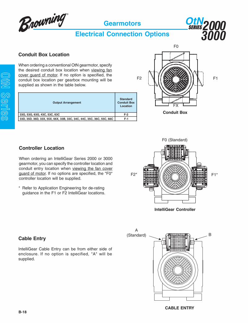
Conduit Box Location
When ordering a conventional OtN gearmotor, specifythe desired conduit box location when viewing fancover guard of motor. If no option is specified, theconduit box location per gearbox mounting will besupplied as shown in the table below.
Controller Location
When ordering an IntelliGear Series 2000 or 3000gearmotor, you can specify the controller location andconduit entry location when viewing the fan coverguard of motor. If no options are specified, the "F0"controller location will be supplied.
Cable Entry
IntelliGear Cable Entry can be from either side ofenclosure. If no option is specified, "A" will besupplied.
CABLE ENTRY
tnemegnarrAtuptuOdradnatS
xoBtiudnoCnoitacoL
C36,C35,C34,G36,G35,G33 2-F
C66,C55,C63,C53,C44,C43,C33,B33,X66,X55,X33,D63,D53,D33 1-F
Gearmotors
Electrical Connection Options
* Refer to Application Engineering for de-ratingguidance in the F1 or F2 IntelliGear locations.
FX

B-19
20003000
SERIESOtN
OtN Series
*Indicates borderline maximum rating for holding loads only.
TABLE 1
tupnIdeepShgiH-sgnitaRPH.xaM ekarB
eloP4mpr0081
eloP4mpr0051
eloP6mpr0021
eloP6mpr0001
euqroT)sbl-tf(
1 4/3 2/1 2/1 32 2/11 1 1 63 2 2 *2/11 015 3 3 2 51
2/17 5 5 3 5201 *01 2/17 5 5351 01 01 2/17 0502 *02 51 01 0752 02 51 01 5703 *03 02 *02 50104 03 52 02 52105 04 *04 03 571
Inverter Duty Gearmotors
Motor Modifications
Improvements in OtN helical-bevel designs begin with threephase motor designs that now incorporate an upgraded wire andvarnish treatment called Allguard. This makes the standardthree phase gearmotors suitable for use with inverters in manyapplications. A one year warranty will be extended for 3:1 (60 -20 Hz) constant torque for standard efficiency design motorsand 4:1 (60 - 15 Hz) constant torque for premium efficiencydesign motors providing the following conditions are met:
• Motor is non-hazardous 3 phase > 48 frame• Cable length to controller ≤ 100 ft• Line voltage is ≤ 480 VAC• Thermal protection is not required
For all other conditions of operation, including up to 575 VACand for hazardous location service, select a Varidyne inverterduty motor design. These designs include thermostats inwinding, a 3 year warranty on the motor and full compliance withNEMA MG1 Part 31.
M1 Brakes
DesignThese mounted brakes have a direct acting, spring set,electromagnetically released disc design. When power to thebrake motor is interrupted, the brake will set and hold. Whenpower is restored, the brake will automatically release.
Brake torque must be specified when ordering. Table 1 givesbrake torque for stopping and holding loads not greater than fullload motor torque. An asterisk indicates borderline maximumratings and should be considered only for holding loads. Referapplications involving high inertia loads or frequent starts andstops to Application Engineering for review.
EnclosuresStandard - Suitable for most indoor, non-hazardousapplications. Stock shur-stop brakes have this enclosure.
Waterproof/dust-tight - For applications requiring additionalbrake protection such as washdown or Corro-Duty. Not suitablefor hazardous Class 2 dust applications. Subject to productionlead time.
Explosionproof - When a brake is to be mounted on anexplosionproof gearmotor, the brake must have UL approvalequal to that of the motor end. Brakes are rated class I group D,class II groups F & G temperature code T3B. Subject toproduction lead-time. Refer all 56, 140T motor framerequirements for explosionproof brakes to ApplicationEngineering before quoting.
Gearmotors
Modifications, Options and Accessories
Operating VoltageProduction brakes through 15 lb. ft. are supplied with 230/460volt coils. Brakes 25 lb. ft. and larger are supplied with 460 voltcoils. For brakes to operate at a different frequency or voltage,or for brakes to operate from a separate power supply, refer toEmerson Power Transmission Application Engineering. Brakesare furnished with leads suitable for external connection.
MountingBrakes listed in Table 1 are motor mounted. Brakes through 6lb. ft. are suitable for all mounting positions. For brakes 10through 35 lb. ft., specify mounting orientation of brakegearmotor. Where vertical mounting of brakes 50 lb. ft. or largeris required, refer to Emerson Power Transmission ApplicationEngineering with mounting and application details.

20003000
SERIESOtN
B-20
OtN Series
TABLE 2PH emarF semarFraeGelbawollA
61./33. 65 egatS-35-2seziSegatS-6roegatS-58-2seziS
52./05. 65 egatS-35-2seziSegatS-6roegatS-58-2seziS
83./57. T341 egatS-35-2seziSegatS-6roegatS-58-2seziS
05./0.1 T541 egatS-35-2seziSegatS-6roegatS-58-2seziS
57./5.1 YT541 egatS-35-2seziSegatS-6roegatS-58-2seziS
0.1/0.2 T281 egatS-37-2seziSegatS-6roegatS-58-3seziS
5.1/0.3 T481 egatS-37-2seziSegatS-6roegatS-58-3seziS
5.2/0.5 T512 egatS-38-3seziSegatS-6roegatS-58-6seziS
57.3/5.7 T452 egatS-38-4seziSegatS-6roegatS-58-6seziS
5/01 T652 egatS-38-4seziSegatS-6roegatS-58-6seziS
5.7/51 T482 egatS-38-5seziSegatS-6roegatS-58eziS
01/02 T682 egatS-38-5seziSegatS-6roegatS-58eziS
5.21/52 T423 egatS-38-7seziS51/03 T623 egatS-38-7seziS
ycneuqerF PH03hguorhTsegatloVesahP3zH06 575,064,064/032,032,002zH05 ,083,044/022,083/022,032,022,002
575,005,064,514
Motor Modifications Continued
M5 Frequency - 50 HzMotors for operation at 3 phase 50 Hz are available. Standard 50Hz voltage (detailed in M6) do not require voltage modification.The published output speed, based on 1750 RPM input, will bereduced by a factor of (1.2) at the same gear ratio. Example: 100RPM output, 60 Hz, 1750 RPM input is 83 RPM output, 50 Hz,1450 RPM input.
M6 Voltage (3 Phase Only)Standard voltages are listed in the table below. Other voltagesare available and must be specified at order entry and requirespecial voltage adder.
M7 InsulationStandard 3 phase TEFC and Corro-Duty motor ends havepremium Q3 class F insulation standard. Single phase TEFCand explosionproof motor ends have class B insulation asstandard. Class H insulation and tropical protection are avail-able from production on 3 phase motors only (class H notavailable on explosionproof).
M8 Space HeatersSpace heaters are recommended for gearmotors installed indamp locations to prevent condensation on the motor windingswhen the motor is not operating. Leads are brought to thestandard motor conduit box. Space heater voltage (115, 230,460 volts) must be specified when the order is entered.
M9 Thermal Protection - ThermostatsThis protection uses a bi-metal disc thermostat, embedded in themotor winding, connected into the holding circuit of the motorstarter. The sensor opens the control circuit, shutting down themotor on over temperature. Thermostats give protection forrunning overload, abnormally high ambient, voltage unbalance,high or low voltage and ventilation failure. Thermostats will notgive protection for locked rotor, starting overload and singlephasing.
M10 Thermal Protection - Therma-SentryTherma-Sentry is a full protection system that consists of a solidstate electronic controller and thermistor temperature sensorsembedded in the motor winding. In addition to all the protectionsprovided by a thermostat, Therma-Sentry also protects againstlocked rotor, starting overload and single phasing. The Therma-Sentry system requires only two leads to connect to the starterpanel. The Therma-Sentry controller is supplied loose to beseparately mounted and separately excited.
M2 Premium EfficiencyPremium efficiency motor designs are available starting at 1 HPto meet customer specifications or NRCan legislation.Corro-Duty motors ≥ 3 HP and all inverter duty motors meetpremium efficiency requirements as standard. TEFC and Corro-Duty motor ends from 1 through 2 HP are design C and thereforeare exempt from NRCan efficiency requirements.
M3 Multi-Speed (3 Phase Only)Gearmotors with 1800 RPM motors as standard can be suppliedwith two speed, one winding, constant torque,1800/900 RPM, 1.0 service factor, TEFC motor ends. Note thatchange in motor frame may change gearbox size. Thus if gearframe is not within allowable range, it may be necessary tochange gear frame size.
M4 Canopy CapA canopy cap can be supplied for protection from drippingliquids entering fan end of gearmotor when mounted in amotor fan up position (V5).
Gearmotors
Modifications, Options and Accessories
Motor Modifications Continued

B-21
20003000
SERIESOtN
OtN Series
Gearmotor Modifications
M11 Corro-DutyCorro-Duty gearmotors are designed for applications in foodprocessing, chemical, poultry and any other industries that willbe subjected to extreme humidity, washdown, steam,detergents and mild acids. Construction of Corro-Dutygearmotors begins with a Corro-Duty cast iron motor (56 and140T frames are rolled steel) and normally closed breather inthe gear case. The exterior of the entire unit is then painted inone of the two options chosen at order entry.
Option #1 - Corro-Duty grey• 3 step paint system using 316 stainless
steel paint• Light grey semigloss finish• USDA and FDA approved
Option #2 - Corro-Duty white• 2 step paint system using epoxy paint• White gloss finish• USDA and FDA approved
M12 Normally Closed BreatherThis breather protects against lubricant contamination inapplications with flying dust, lint or washdown. A normallyclosed breather is standard on frames sizes 2 through 5, orit may be added to frames 6 though 8 by specifying thisoption.
M13 NPT AdapterThese adapters convert metric threads of breather, drain and/or oil level holes in the reducer to standard NPT threads. Theyare required for customer additions of site glasses, sight tubes,special breathers and other plumbing accessories. Theadapter(s) is supplied loose for mounting by others.
Gearmotor Modifications
Gearmotors
Modifications, Options and Accessories
Face and Flanged Output(Designated under Brackets and Shafts)Gearmotors with faced or flanged outputs are available fromstock. Refer to page B-14 and individual dimension pages foroptions available based on gear frame size.
Synthetic OilOtN gearmotors are supplied factory-filled with a premiumsynthetic oil. Refer to page B-187 for complete details oflubricants.
raeGemarF eziS rebmuNtraP
5-2 TFPN"4/1 61263408-6 TFPN"4/3 8126340
M18 Oil Level View PortThis clear port is installed in place of the oil level plug. Itallows maintenance personnel a convenient means ofchecking for proper oil level without removing plugs. ProperView Port part numbers are:
raeGemarF eziS rebmuNtraP
5-2 elaMPPSB"4/1 63953408-6 elaMPPSB"4/3 8395340
M15 Export BoxingExport boxing can be provided for "underdeck" transport. Whenthe quantity of OtN gearmotors exceeds five units, refer to thesales department for the most economical accommodations.
M16 Special NameplateUnits can be provided with limited, additional, special informationon the standard product nameplate. When requested, a specialnameplate may be provided and stamped with custom markings.
20003000
SERIESOtN
B-22
OtN Series
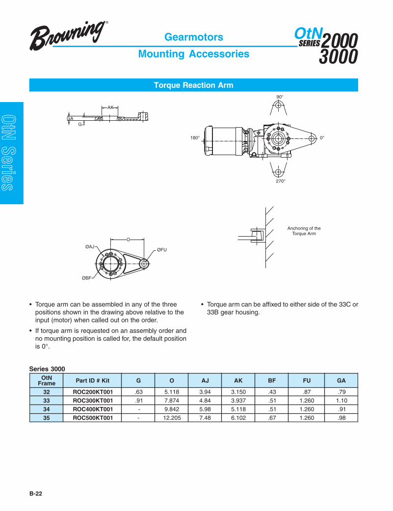
Torque Reaction Arm
Gearmotors
Mounting Accessories
ØAJ
O
ØBF
90°
ØFU
Anchoring of theTorque Arm
GA
180° 0°
270°
G
AK
NtOemarF tiK#DItraP G O JA KA FB UF AG
23 100TK002COR 36. 811.5 49.3 051.3 34. 78. 97.
33 100TK003COR 19. 478.7 48.4 739.3 15. 062.1 01.1
43 100TK004COR - 248.9 89.5 811.5 15. 062.1 19.
53 100TK005COR - 502.21 84.7 201.6 76. 062.1 89.
Series 3000
• Torque arm can be assembled in any of the threepositions shown in the drawing above relative to theinput (motor) when called out on the order.
• If torque arm is requested on an assembly order andno mounting position is called for, the default positionis 0°.
• Torque arm can be affixed to either side of the 33C or33B gear housing.

B-23
20003000
SERIESOtN
OtN Series
raeGemarF
traPrebmuN A 1D G 1H 2H .xam3H L 1L 2L 1S
.nim
62 9746890 89.31 57. 05.2 16.31 05.4 05.1 38.53 64.72 80.62 18.0
72 9746890 45.61 57. 05.2 95.41 05.4 05.1 38.53 81.62 08.42 18.0
82 0846890 80.02 88. 00.4 76.81 00.6 88.1 13.34 96.13 21.03 49.0
A
L2
L
L1
H2
D1
S1
G
H3
H1
Torque Reaction Arm
Gearmotors
Mounting Accessories
Series 2000
• Torque arm can be assembled with attachment pointon the input side or 180° opposite this, as shownabove.
• Torque arm can be attached onto feet on either sideof the gear housing as you face opposite the input(motor).

20003000
SERIESOtN
B-24
OtN Series
Stabilizer Ring
Tapered Bushings
Each Series 3000 OtN can be ordered with a TaperedBushed Output. This “33B” mounting configuration willinclude the appropriate bushing kit unassembled whena bore is defined at order entry. The table below showsthe various stocked bushing bores for each OtN framethat can be specified. Each bushing kit is supplied withbushing, hardware for mounting and a stabilizer ring. Ifbushings are required as a spare or bore changed inthe field, refer to the OtN 3000 frame and select therequired kit from below.
NtOemarF
.aeMtinU
gnihsuB.oN
eroBtaesyeKtfahS
deriuqeRepyT
rezilibatShtdiWgniR
euqroTtloB thgieW).sbl(eziStloB .sbl-.tF
2333
hcnI
210PBT701 4/3 8/73x23/3x61/3 1
397.0 4/11x81-61/5 61
6.2410PBT701 8/7 8/73x23/3x61/3 1 5.2510PBT701 61/51 8/73x8/1x4/1 2 4.2001PBT701 1 8/73x8/1x4/1 2 3.2101PBT701 61/11 8/73x8/1x4/1 2 1.2201PBT701 8/11 8/73x8/1x4/1 2 0.2
301PBT701 61/31 8/73x8/1x4/1 2 9.1401PBT701 4/11 8/73x8/1x4/1 2 8.1501PBT701 61/51 8/73x23/5x61/5 2 6.1601PBT701 8/31 8/73x23/5x61/5 2 5.1701PBT701 61/71 8/73x61/3x8/3 2 5.1
*cirteM MM03PBT701 mm03 )mm(49x4x8 2 9.1MM53PBT701 mm53 )mm(49x5x01 2 5.1
43
hcnI
510PBT511 61/51 8/14x8/1x4/1 1
558.0 4/11x61-8/3 92
6001PBT511 1 8/14x8/1x4/1 1 9.5101PBT511 61/11 8/14x8/1x4/1 1 7.5201PBT511 8/11 8/14x8/1x4/1 1 6.5301PBT511 61/31 8/14x8/1x4/1 1 4.5
401PBT511 4/11 8/14x8/1x4/1 1 3.5501PBT511 61/51 8/14x23/5x61/5 2 1.5601PBT511 8/31 8/14x23/5x61/5 2 8.4701PBT511 61/71 8/14x61/3x8/3 2 7.4801PBT511 2/11 8/14x61/3x8/3 2 4.4
011PBT511 8/51 8/14x61/3x8/3 2 0.4111PBT511 61/111 8/14x61/3x8/3 2 7.3211PBT511 4/31 8/14x61/3x8/3 2 5.3411PBT511 8/71 8/14x4/1x2/1 2 1.3511PBT511 61/511 8/14x4/1x2/1 2 7.2
*cirteM MM04PBT511 mm04 )mm(001x5x21 2 0.4MM54PBT511 mm54 )mm(001x5.5x41 2 5.3
53
hcnI
601PBT702 8/31 8/15x23/5X61/5 1
040.1 4/11X61-8/3 92
6.93.91.95.8
701PBT702 61/71 8/15X61/3X8/3 1801PBT702 2/11 8/15X61/3X8/3 1011PBT702 8/51 8/15X61/3X8/3 2
111PBT702 61/111 8/15X61/3X8/3 2 3.89.73.79.6
211PBT702 4/31 8/15X61/3X8/3 2411PBT702 8/71 8/15X4/1X2/1 2511PBT702 61/511 8/15X4/1X2/1 2
002PBT702 2 8/15X4/1X2/1 2 6.69.55.51.59.3
202PBT702 8/12 8/15X4/1X2/1 2302PBT702 61/32 8/15X4/1X2/1 2402PBT702 4/12 8/15X4/1X2/1 2702PBT702 61/72 8/15X61/5X8/5 2
*cirteMMM05PBT702 mm05 )mm(521x5.5x41 2 6.6
5.4MM06PBT702 mm06 )mm(521x7x81 2
* Metric bushings have metric bores and require metric keyseats as shown in mm.

B-25
20003000
SERIESOtN
OtN Series
Conveyors - UniformlyLoaded or Fed: Apron, Ass-embly, Belt, Bucket, Chain,Flight, Oven, Screw U I II
Conveyors - Heavy DutyNot Uniformly Fed: Apron,Assembly, Belt, Bucket,Chain, Flight, Oven, Screw M II IILive Roll (Package) U I IIReciprocating, shaker V III III
Cookers (Brewing andDistiling) (Food) U I II
Cooling Tower FansInduced Draft M II IIForced Draft Refer to Application Engineering
Couch (Paper) M - II
Cranes and HoistsMain Hoists Heavy Duty V III III Medium Duty M II IIReversing V II IISkip Hoists M II IITrolley Drive M II IIBridge Drive M II II
CrushersOre or Stone V III III
Cutters (Paper) V - III
Cylinders (Paper) M - II
Dewatering Screens(Sewage) M II II
Disc Feeders U I II
Distilling (See Brewing)
Double Acting Pumps2 or more Cylinders M II IISingle Cylinder Refer to Application Engineering
Dough Mixer (Food) M II II
Draw Bench(Metal Mills)Carriage & Main Drive V III III
DredgesCable Reels M II -Conveyors M II IICutter Head Drives V III IIIJig Drives V III IIIManeuvering Winches M II -Pumps M II IIScreen Drives V III IIIStackers M II IIUtility Winches M II -
BucketConveyors, Uniform U I IIConveyors, Heavy Duty M II IIElevators Cont. U I IIElevators Uniform U I IIElevators, Heavy Duty M II II
CalendersPaper U - IISuper (Paper) U - IIRubber M II IITextile M II II
Cane Knives M II II
Can Filling Machines U I II
Card Machines (Textile) M II II
Car Dumpers V III -
Car Pullers M II -
Cement Kilns Refer to Application Engineering
CentrifugalBlowers, Compressors, Dis-charge Elevators or Pumps U I II
Chain ConveyorsUniformly Loaded or Fed U I IIHeavy Duty M II II
Chemical Feeders(Sewage) U I II
Clarifiers U I II
Classifiers M II II
Clay Working IndustryBrick Press V III IIIBriquette Machine V III IIIClay Working Machinery M II IIPug Mill M II II
Collectors (Sewage) U I II
CompressorsCentrifugal U I IILobe M II IIReciprocating, Multi - Cylinder M II II Single - Cylinder V III III
Concrete MixersContinuous M II IIIntermittent U I -
Converting Machines(Paper) M - II
AgitatorsPaper Mills M II IIPure Liquids U I II
Liquids & Solids M II IILiquids - Variable Density M II II
Apron ConveyorsUniformly Loaded or Fed U I IIHeavy Duty M II II
Apron Feeders M II II
Assembly ConveyorsUniformly Loaded or Fed U I IIHeavy Duty M II II
Ball Mills V III III
BarkingDrums V - IIIHydraulic Auxiliaries V - IIIMechanical V - III
Barscreens (Sewage) U I II
Batchers (Textile) M II II
Beaters and Pulpers(Paper) U - II
Belt ConveyorsUniformly Loaded or Fed U I IIHeavy Duty M II II
Belt Feeders M II II
Bending Rolls(Machine) M II II
Bleachers (Paper) M - II
BlowersCentrifugal U I IILobe M II IIVane U I II
Bottling Machinery U I II
Brewing and DistillingBottling Machinery U I IIBrew Kettles, Cont. Duty U - IICan Filling Machines U I IICookers - Cont. Duty U - IIMash Tubs - Cont. Duty U - IIScale Hoppers - Frequent Starts M II II
Brick Press (Clay Working) V III III
Briquetts Machines (Clay Working) V III III
Up to Over10 10
hrs/day hrs/day
Up to Over10 10
hrs/day hrs/day
Up to Over10 10
hrs/day hrs/day
U: Uniform load M: Moderate shock load V: Heavy shock loadApplication Load Class Application Load Class Application Load Class
Gearmotors
AGMA Application Classifications

20003000
SERIESOtN
B-26
OtN Series
U: Uniform load M: Moderate shock load V: Heavy shock load
Up to Over10 10
hrs/day hrs/day
Application Load Class
Up to Over10 10
hrs/day hrs/day
Up to Over10 10
hrs/day hrs/day
Application Load Class Application Load Class
Dryers (Paper) U - II
Dryers and Coolers(Mills, Rotary) M II II
Dyeing Machinery(Textile) M II II
ElevatorsBucket - Uniform Load U I IIBucket - Heavy Duty M II IIBucket - Continuous U I IICentrifugal Discharge U I IIEscalators U I IIFreight M II IIGravity Discharge U I IIMan Lifts, Passenger Refer to Application Engineering
Escalators U I II
FansCentrifugal M II IICooling Towers Induced Draft M II IIForced Draft Refer to Application EngineeringInduced Draft M II IILarge (Mine, etc.) M II IILarge Industrial M II IILight (Small Diameter) U I II
FeedersApron, belt M II IIDisc U I IIReciprocating V III IIIScrew M II II
FeltStretchers (Paper) U - IIWhippers (Paper) U - II
FlightConveyors, Uniform U I IIConveyors, Heavy M II II
Food IndustryBeet Slicers M II IIBottling, Can Filling Mach. U I IICereal Cookers U I IIDough Mixers M II IIMeat Grinders M II II
Forming Machines(Metal Mills) V III III
Generators (Not welding) U I II
Gravity DischargeElevators U I II
Grit Collectors(Sewage) U I II
Machine ToolsAuxiliary Drives U I IIBending Rolls M II IIMain Drives M II IINotching Press (Belted) Refer to Application Engr.Plate Planers V III IIIPunch Press (Geared) V III IIITapping Machines V III III
Mangle (Textile) M II II
Mash Tubs (Brewing andDistilling) U - II
Meat Grinder (Food) M II II
Metal MillsDraw Bench Carriages & Main Drives V III IIIForming Machines V III IIIPinch, Dryer & Scrubber Rolls Reversing Refer to Application EngineeringSlitters M II IITable Conveyors, Non-Reversing M II III Reversing V - IIIWire Drawing & Flattening Machines M II IIIWire Winding Machines M II II
Mills, Rotary TypeBall, Pebble, Rod V III IIICement Kilns Refer to Application EngineeringCoolers, Dryers, Kilns V II IITumbling Barrels V III III
Mixers (Also see Agitators)Concrete - Continuous M II IIConcrete - Intermittent M I -Constant Density U I IIVariable Density M II II
Nappers (Textile) M II II
Oil IndustryChillers M II IIOil Well Pumping Refer to Application EngineeringParaffin Filter Press M II IIRotary Kilns M II II
Ore Crushers V III III
Oven ConveyorsUniform U I IIHeavy Duty M II II
Hammer Mills V III III
Induced Draft Fans M II II
Jordans (Paper) U - II
Kilns (Mills, Rotary) M II IICement Refer to Application Engineering
Laundry Washers andTumblers M II II
Line ShaftsHeavy Shock Load V III IIIModerate Shock Load M II IIUniform Load U I II
Live Roll ConveyorsPackage U I II
Lobe Blower orCompressors M II II
Log Hauls (Paper andLumber) V III III
Looms (Textile) M II II
Lumber IndustryBarkers - Spindle Feed V II IIIBarkers - Main Drive V III IIICarriage Drive Refer to Application EngineeringConveyors Burner V II III Main or Heavy Duty V II IIIMain Log V III III Re-Saw Merry-Go-Round V II IIISlab V III IIITransfer V II IIIChains - Floor V II IIIChains - Green V II IIICut-Off Saws-Chain V II IIICut-Off Saws-Drag V II IIIDebarking Drums V III IIIFeeds - Edger V II IIIFeeds - Gang V III IIIFeeds - Trimmer V II IIILog Deck V III IIILog Hauls - Incline, Well Type V III IIILog Turning Devices V III IIIPlanner Feed V II IIIPlaner Tilting Hoists V II IIIRolls - Live-Off Bearing Roll Cases V III IIISorting Table V II IIITipple Hoist V II IIITransfers - Chain V II IIITransfers - Craneway V II IIITray Drives V II III
Gearmotors
AGMA Application Classifications

B-27
20003000
SERIESOtN
OtN Series
U: Uniform load M: Moderate shock load V: Heavy shock load
Up to Over10 10
hrs/day hrs/day
Application Load Class
Up to Over10 10
hrs/day hrs/day
Up to Over10 10
hrs/day hrs/day
Application Load Class Application Load Class
Paper MillsAgitator (Mixers) M II IIBarker - Auxiliaries - Hyd. V - IIIBarker, Mechanical V - IIIBarking Drum V - IIIBeater & Pulper M - IIBleacher M - IICalenders M - IICalenders - Super M - IIConverting Mach.- Except Cutters - Platers M - IIConveyors M - IICouch M - IICutters, Platers V - IIICylinders U - IIDryers U - IIFelt Stretchers U - IIFelt Whippers V - IIIJordans M - IILog Haul V - IIIPresses M - IIPulp Machine Reels M - IIStock Chests M - IISuction Rolls M - IIWashers & Thickeners M - IIWinders M - II
Passenger Elevators Refer to Application Engineering
Pebble Mills V III III
Plate Planers V III III
Presses (Paper) V - III
Proportioning Pumps M II II
Pub Mills (Clay) M II II
Pullers (Barge Haul) V III III
Pulp Machine Reels U - II
PumpsCentrifugal U I IIProportioning M II IIReciprocating Single Act., 3 or more cyl. M II II Double Act., 2 or more cyl. M II II Single Act., 1 or 2 cyl. Refer to Application Engr.Rotary: Gear, Lobe, Vane U I II
Punch Press(Gear Driven) V III III
ReciprocatingConveyors, Feeders V III III
Reciprocating CompressorsMulti-Cylinder M II IISingle cylinder V III III
Rod Mills V III III
RotaryPumps, Gear, Lobe, Vane U I IIScreens (Sand or Gravel) V II II
Rubber IndustryMixer V III IIIRubber Calender M II IIRubber Mill (2 or more) M II IISheeter M II IITire Building Machines Refer to Application Engr.Tire, Tube Press Openers Refer to Application Engr.Tubers & Strainers M II II
Sand Mullers Refer to Application Engr.
ScreensAir Washing U I IIRotary - Sand or Gravel M II IITraveling Water Intake U I II
Screw ConveyorsUniform U I IIHeavy Duty or Feeder M II II
Scum Breakers(Sewage) M II II
Sewage DisposalAerators Refer to Application EngineeringBar Screens U I IIChemical Feeders U I IICollectors U I IIDewatering Screens M II IIGrit Collectors U I IIScum Breakers M II IISlow or Rapid Mixers M II IISludge Collectors U I IIThickeners M II IIVacuum Filters M II II
Shaker Conveyors V III III
Sheeters (Rubber) M II II
Singls Acting Pump1 or 2 Cylinders Refer to Application Engineering3 or more Cylinders M II II
Skip Hoist M II II
Slab Pushers M II II
Slitters (Metal) M II II
Sludge Collectors(Sewage) U I II
Soapers (Textile) M II II
Spinners (Textile) M II II
Steering Gears M II II
Stock Chests(Paper) U - ii
Stokers U I II
Stone Crushers V III III
Suction Rolls(Paper) U - II
Table Conveyors (Metal Mills) Non-Reversing V II III
Reversing V - III
Tenter Frames(Textile) M II II
Textile IndustryBatchers M II IICalenders M II IICard Machines M II IICloth Finishing Mach. (Cal- enders, Dryers, Pads, Tenters, Washers) M II IIDry Cans M II IIDyeing Machinery M II IIKnitting Machinery Refer to Application Engr.Looms, Mangles, Nappers M II IIRange Drives Refer to Application Engr.Soapers, Spinners M II IITenter Frames M II IIWinders M II IIYarn Preparatory Mach.(Cards, Spinners, Slashers) M II II
Thickeners (Sewage) M II II
Tumbling Barrels V III III
Vacuum Filters(sewage) M II II
Vane Blowers U I II
Winches (Dredges) M II -
Winders(Paper) U - II(Textile) M II II
Windlass M II II
WireDrawing Machines M II IIIWinding Machines M II II
Applications not listed in this table, or where the user has data indicating the severity of this usage to be greater thanaverage, should be referred to Application Engineering.
Gearmotors
AGMA Application Classifications

20003000
SERIESOtN
B-28
OtN Series
General Specifications: Totally enclosed, 60 hertz, 40°C ambient, continuous duty.
Output AGMA Service Output Torque OHL ΔΔΔΔΔ Nominal Frame Size Std. Motorrpm Class Factor in-lb lb Ratio Gear Motor Types ◊◊◊◊◊
179 I, II, III 3+ 55 1163 10 3243 48 T,S141 I, II, III 3+ 70 1250 12.5 3243 48 T,S126 I, II, III 3+ 79 1295 14 3243 48 T,S109 I, II, III 3+ 91 1254 16 3243 48 T,S105 I, II, III 3+ 94 1367 18 3243 48 T,S86 I, II, III 3+ 115 1456 20 3243 48 T,S76 I, II, III 3+ 129 1490 22.4 3243 48 T,S73 I, II, III 3+ 136 1490 25 3243 48 T,S64 I, II, III 3+ 154 1490 28 3243 48 T,S57 I, II, III 3+ 174 1490 31.5 3243 48 T,S50 I, II, III 3+ 197 1490 35.5 3243 48 T,S44 I, II, III 3+ 223 1490 40 3243 48 T,S39 I, II, III 3+ 255 1490 45 3243 48 T,S34 I, II, III 3+ 288 1490 50 3243 48 T,S32 I, II, III 3+ 306 1490 56 3243 48 T,S27 I, II, III 3+ 363 1490 63 3243 48 T,S26 I, II, III 3+ 384 1490 71 3243 48 T,S23 I, II, III 3+ 439 1490 80 3243 48 T,S20 I, II, III 3+ 490 1490 90 3243 48 T,S18 I, II, III 3+ 549 1490 100 3243 48 T,S15 I, II, III 3+ 638 1490 112 3243 48 T,S14 I, II, III 3+ 701 1490 125 3243 48 T,S12 I, II, III 3+ 802 1490 140 3243 48 T,S11 I, II, III 3+ 881 1490 160 3243 48 T,S
Gearmotors
1/6 HP
◊ Standard Motor Types (see page B-15 for product codes)T TEFC, three phase, 208-230/460 or 575 voltsS TEFC, single phase, 115/230 volts
ΔΔΔΔΔ Overhung load rating is at shaft midpoint.
Refer to Application Engineering for speeds slower than shown.

B-29
20003000
SERIESOtN
OtN Series
Output AGMA Service Output Torque OHL ΔΔΔΔΔ Nominal Frame Size Std. Motorrpm Class Factor in-lb lb Ratio Gear Motor Types ◊◊◊◊◊
179 I, II, III 3+ 83 1141 10 3243 48 T,S141 I, II, III 3+ 105 1228 12.5 3243 48 T,S126 I, II, III 3+ 118 1273 14 3243 48 T,S109 I, II, III 3+ 136 1332 16 3243 48 T,S105 I, II, III 3+ 141 1355 18 3243 48 T,S86 I, II, III 3+ 173 1434 20 3243 48 T,S76 I, II, III 3+ 194 1485 22.4 3243 48 T,S73 I, II, III 3+ 204 1490 25 3243 48 T,S64 I, II, III 3+ 231 1490 28 3243 48 T,S57 I, II, III 3+ 261 1490 31.5 3243 48 T,S50 I, II, III 3+ 295 1490 35.5 3243 48 T,S44 I, II, III 3+ 335 1490 40 3243 48 T,S39 I, II, III 3+ 383 1490 45 3243 48 T,S34 I, II, III 3+ 432 1490 50 3243 48 T,S32 I, II, III 3+ 458 1490 56 3243 48 T,S27 I, II, III 3+ 545 1490 63 3243 48 T,S26 I, II, III 3+ 576 1490 71 3243 48 T,S23 I, II, III 3+ 658 1490 80 3243 48 T,S20 I, II, III 3+ 735 1490 90 3243 48 T,S18 I, II, III 3+ 824 1490 100 3243 48 T,S15 I, II, III 3+ 958 1490 112 3243 48 T,S14 I, II, III 3+ 1051 1490 125 3243 48 T,S12 I, II, III 3+ 1203 1490 140 3243 48 T,S11 I, II, III 3+ 1322 1490 160 3243 48 T,S
Gearmotors
1/4 HP
General Specifications: Totally enclosed, 60 hertz, 40°C ambient, continuous duty.
◊ Standard Motor Types (see page B-15 for product codes)T TEFC, three phase, 208-230/460 or 575 voltsS TEFC, single phase, 115/230 volts
ΔΔΔΔΔ Overhung load rating is at shaft midpoint.
Refer to Application Engineering for speeds slower than shown.

20003000
SERIESOtN
B-30
OtN Series
Output AGMA Service Output Torque OHL ΔΔΔΔΔ Nominal Frame Size Std. Motorrpm Class Factor in-lb lb Ratio Gear Motor Types ◊◊◊◊◊
179 I, II, III 3+ 110 1119 10 3243 56 T,C,S,X,IG141 I, II, III 3+ 139 1206 12.5 3243 56 T,C,S,X,IG126 I, II, III 3+ 155 1251 14 3243 56 T,C,S,X,IG109 I, II, III 3+ 180 1310 16 3243 56 T,C,S,X,IG105 I, II, III 3+ 186 1323 18 3243 56 T,C,S,X,IG86 I, II, III 3+ 228 1412 20 3243 56 T,C,S,X,IG76 I, II, III 3+ 256 1463 22.4 3243 56 T,C,S,X,IG73 I, II, III 3+ 270 1487 25 3243 56 T,C,S,X,IG64 I, II, III 3+ 305 1490 28 3243 56 T,C,S,X,IG57 I, II, III 3+ 345 1490 31.5 3243 56 T,C,S,X,IG50 I, II, III 3+ 389 1490 35.5 3243 56 T,C,S,X,IG44 I, II, III 3+ 442 1490 40 3243 56 T,C,S,X,IG39 I, II, III 3+ 506 1490 45 3243 56 T,C,S,X,IG34 I, II, III 3+ 570 1490 50 3243 56 T,C,S,X,IG32 I, II, III 3+ 605 1490 56 3243 56 T,C,S,X,IG27 I, II, III 3+ 719 1490 63 3243 56 T,C,S,X,IG26 I, II, III 3+ 761 1490 71 3243 56 T,C,S,X,IG23 I, II, III 3+ 869 1490 80 3243 56 T,C,S,X,IG20 I, II, III 3+ 970 1490 90 3243 56 T,C,S,X,IG18 I, II, III 3+ 1087 1490 100 3243 56 T,C,S,X,IG15 I, II, III 3+ 1264 1490 112 3243 56 T,C,S,X,IG14 I, II, III 2.9 1387 1490 125 3243 56 T,C,S,X,IG12 I, II, III 2.5 1588 1490 140 3243 56 T,C,S,X,IG11 I, II, III 2.3 1745 1490 160 3243 56 T,C,S,X,IG
10.1 I, II, III 3+ 1869 2090 180 3365 56 T,C,S,X,IG9.8 I, II, III 2.1 1912 1490 180 3245 56 T,C,S,Xo,IG9.4 I, II 1.9 2093 1490 125 3243 56 † T,C,X8.9 I, II, III 3+ 2106 2090 200 3365 56 T,C,S,X,IG8.9 I, II 1.9 2116 1490 200 3245 56 T,C,S,Xo,IG8.5 I, II, III 3+ 2312 2090 140 3363 56 † T,C,X8.5 I, II 1.8 2224 1490 224 3245 56 T,C,S,Xo,IG8.2 I, II 1.7 2396 1490 140 3243 56 † T,C,X7.9 I, II, III 3+ 2385 2090 224 3365 56 T,C,S,X,IG7.4 I, II 1.5 2633 1490 160 3243 56 † T,C,X7.3 I, II, III 2.7 2700 2090 160 3363 56 † T,C,X7.1 I, II 1.5 2643 1490 250 3245 56 T,C,S,Xo,IG6.9 I, II, III 2.6 2707 2090 250 3365 56 T,C,S,X,IG6.7 I, II 1.4 2825 1490 280 3245 56 T,C,S,Xo,IG6.1 I, II, III 2.3 3094 2090 280 3365 56 T,C,S,X,IG
Gearmotors
1/3 HP
General Specifications: Totally enclosed, 60 hertz, 40°C ambient, continuous duty.
◊ Standard Motor Types (see page B-15 for product codes)T TEFC, three phase, 208-230/460 or 575 voltsS TEFC, single phase, 115/230 voltsC Corro-Duty, three phase, 230/460 or 575 voltsX° Explosionproof, CL1 group D, three phase, 230/460 or 575 voltsX Explosionproof, CI 1 group D, CI 2 groups F&G, three phase, 230/460 or 575 voltsIG IntelliGear variable speed for 1-ph/115V, 1-ph/230V, 3-ph/230V, or 3-ph/460V power supplies, NEMA 4/12
Δ Overhung load rating is at shaft midpoint.
† Denotes 6-pole (1200 rpm) motor.

B-31
20003000
SERIESOtN
OtN Series
General Specifications: Totally enclosed, 60 hertz, 40°C ambient, continuous duty.
Gearmotors
1/3 HP (Continued)
Output AGMA Service Output Torque OHL ΔΔΔΔΔ Nominal Frame Size Std. Motorrpm Class Factor in-lb lb Ratio Gear Motor Types ◊◊◊◊◊
5.9 I 1.2 3169 1490 315 3245 56 T,C,S,Xo,IG5.4 I, II, III 2.0 3491 2090 315 3365 56 T,C,S,X,IG5.1 I 1.1 3685 1490 355 3245 56 T,C,S,Xo,IG5.1 I, II 1.9 3706 2090 355 3365 56 T,C,S,X,IG4.7 I 1.0 3975 1490 400 3245 56 T,C,S,Xo,IG4.5 I, II, III 3+ 4147 2875 400 3475 56 T,C,S,X,IG4.3 I, II 1.6 4405 2090 400 3365 56 T,C,S,X,IG4.0 I, II 1.5 4662 2090 450 3365 56 T,C,S,X,IG4.0 I, II, III 3+ 4695 2875 450 3475 56 T,C,S,X,IG3.6 I, II, III 2.8 5178 2875 500 3475 56 T,C,S,X,IG3.5 I 1.3 5329 2090 500 3365 56 T,C,S,X,IG3.2 I, II, III 2.4 5887 2875 560 3475 56 T,C,S,X,IG3.2 I 1.2 5941 2090 560 3365 56 T,C,S,X,IG2.8 I 1.1 6661 2090 630 3365 56 T,C,S,X,IG2.8 I, II, III 2.1 6725 2875 630 3475 56 T,C,S,X,IG2.5 I, II 1.9 7595 2875 710 3475 56 T,C,S,X,IG2.4 I, II, III 2.9 7961 4100 800 3585 56 T,C,S,X,IG2.3 I, II 1.8 8057 2875 800 3475 56 T,C,S,X,IG2.0 I, II, III 2.5 9303 4100 900 3585 56 T,C,S,X,IG2.0 I, II 1.5 9572 2875 900 3475 56 T,C,S,X,IG1.9 I, II 1.4 10120 2875 1000 3475 56 T,C,S,X,IG1.8 I, II, III 2.2 10485 4100 1000 3585 56 T,C,S,X,IG1.6 I, II, III 2.0 11871 4100 1120 3585 56 T,C,S,X,IG1.5 I 1.1 12730 2875 1120 3475 56 T,C,S,X,IG1.4 I, II 1.7 13482 4100 1250 3585 56 T,C,S,X,IG1.3 I, II 1.7 14170 4100 1400 3585 56 T,C,S,X,IG1.3 I 1.0 14557 2875 1250 3475 56 T,C,S,X,IG1.2 I, II 1.5 16104 4100 1600 3585 56 T,C,S,X,IG1.0 I 1.3 18403 4100 1800 3585 56 T,C,S,X,IG0.91 I 1.1 20766 4100 2000 3585 56 T,C,S,X,IG0.85 I 1.1 22034 4100 2240 3585 56 T,C,S,X,IG
◊ Standard Motor Types (see page B-15 for product codes)T TEFC, three phase, 208-230/460 or 575 voltsS TEFC, single phase, 115/230 voltsC Corro-Duty, three phase, 230/460 or 575 voltsX° Explosionproof, CL1 group D, three phase, 230/460 or 575 voltsX Explosionproof, CI 1 group D, CI 2 groups F&G, three phase, 230/460 or 575 voltsIG IntelliGear variable speed for 1-ph/115V, 1-ph/230V, 3-ph/230V, or 3-ph/460V power supplies, NEMA 4/12
Δ Overhung load rating is at shaft midpoint.
† Denotes 6-pole (1200 rpm) motor.

20003000
SERIESOtN
B-32
OtN Series
Output AGMA Service Output Torque OHL ΔΔΔΔΔ Nominal Frame Size Std. Motorrpm Class Factor in-lb lb Ratio Gear Motor Types ◊◊◊◊◊
179 I, II, III 3+ 166 1108 10 3243 56 T,C,S,X,IG141 I, II, III 3+ 210 1193 12.5 3243 56 T,C,S,X,IG126 I, II, III 3+ 236 1236 14 3243 56 T,C,S,X,IG109 I, II, III 3+ 273 1293 16 3243 56 T,C,S,X,IG105 I, II, III 3+ 281 1305 18 3243 56 T,C,S,X,IG86 I, II, III 3+ 346 1389 20 3243 56 T,C,S,X,IG76 I, II, III 3+ 388 1438 22.4 3243 56 T,C,S,X,IG73 I, II, III 3+ 408 1461 25 3243 56 T,C,S,X,IG64 I, II, III 3+ 463 1490 28 3243 56 T,C,S,X,IG57 I, II, III 3+ 522 1490 31.5 3243 56 T,C,S,X,IG50 I, II, III 3+ 590 1490 35.5 3243 56 T,C,S,X,IG44 I, II, III 3+ 669 1490 40 3243 56 T,C,S,X,IG39 I, II, III 3+ 766 1490 45 3243 56 T,C,S,X,IG34 I, II, III 3+ 864 1490 50 3243 56 T,C,S,X,IG32 I, II, III 3+ 917 1490 56 3243 56 T,C,S,X,IG27 I, II, III 3+ 1090 1490 63 3243 56 T,C,S,X,IG26 I, II, III 3+ 1152 1490 71 3243 56 T,C,S,X,IG23 I, II, III 3+ 1317 1490 80 3243 56 T,C,S,X,IG20 I, II, III 2.7 1469 1490 90 3243 56 T,C,S,X,IG18 I, II, III 2.4 1647 1490 100 3243 56 T,C,S,X,IG15 I, II, III 2.1 1915 1490 112 3243 56 T,C,S,X,IG14 I, II 1.9 2102 1490 125 3243 56 T,C,S,X,IG14 I, II, III 3+ 2119 2090 125 3363 56 T,C,S,X,IG13 I, II, III 3+ 2322 2090 140 3363 56 T,C,S,X,IG12 I, II 1.7 2407 1490 140 3243 56 T,C,S,X,IG11 I, II 1.5 2644 1490 160 3243 56 T,C,S,X,IG11 I, II, III 2.6 2712 2090 160 3363 56 T,C,S,X,IG10 I, II, III 2.5 2832 2090 180 3365 56 T,C,S,X,IG10 I, II 1.4 2897 1490 180 3245 56 T,C,S,Xo,IG9.4 I 1.3 3171 1490 125 3243 56 † T,C,X9.3 I, II, III 2.2 3196 2090 125 3363 56 † T,C,X8.9 I, II, III 2.2 3190 2090 200 3365 56 T,C,S,X,IG8.9 I 1.2 3207 1490 200 3245 56 T,C,S,Xo,IG8.5 I, II, III 2.1 3503 2090 140 3363 56 † T,C,X8.5 I 1.2 3369 1490 224 3245 56 T,C,S,Xo,IG8.3 I, II, III 3+ 3554 2875 140 3473 56 † T,C,X8.2 I 1.1 3631 1490 140 3243 56 † T,C,X7.9 I, II, III 2.0 3614 2090 224 3365 56 T,C,S,X,IG7.5 I, II, III 3+ 3938 2875 160 3473 56 † T,C,X
Gearmotors
1/2 HP
General Specifications: Totally enclosed, 60 hertz, 40°C ambient, continuous duty.
◊ Standard Motor Types (see page B-15 for product codes)T TEFC, three phase, 208-230/460 or 575 voltsS TEFC, single phase, 115/230 voltsC Corro-Duty, three phase, 230/460 or 575 voltsX° Explosionproof, CL1 group D, three phase, 230/460 or 575 voltsX Explosionproof, CI 1 group D, CI 2 groups F&G, three phase, 230/460 or 575 voltsIG IntelliGear variable speed for 1-ph/115V, 1-ph/230V, 3-ph/230V, or 3-ph/460V power supplies, NEMA 4/12
Δ Overhung load rating is at shaft midpoint.
† Denotes 6-pole (1200 rpm) motor.

B-33
20003000
SERIESOtN
OtN Series
General Specifications: Totally enclosed, 60 hertz, 40°C ambient, continuous duty.
Gearmotors
1/2 HP (Continued)
Output AGMA Service Output Torque OHL ΔΔΔΔΔ Nominal Frame Size Std. Motorrpm Class Factor in-lb lb Ratio Gear Motor Types ◊◊◊◊◊
◊ Standard Motor Types (see page B-15 for product codes)T TEFC, three phase, 208-230/460 or 575 voltsS TEFC, single phase, 115/230 voltsC Corro-Duty, three phase, 230/460 or 575 voltsX° Explosionproof, CL1 group D, three phase, 230/460 or 575 voltsX Explosionproof, CI 1 group D, CI 2 groups F&G, three phase, 230/460 or 575 voltsIG IntelliGear variable speed for 1-ph/115V, 1-ph/230V, 3-ph/230V, or 3-ph/460V power supplies, NEMA 4/12
Δ Overhung load rating is at shaft midpoint.
† Denotes 6-pole (1200 rpm) motor.
7.4 I 1.0 3989 1490 160 3243 56 † T,C,X7.3 I, II 1.8 4091 2090 160 3363 56 † T,C,X7.1 I 1.0 4004 1490 250 3245 56 T,C,S,Xo,IG7.0 I, II, III 3+ 4069 2875 250 3475 56 T,C,S,X,IG6.9 I, II 1.7 4102 2090 250 3365 56 T,C,S,X,IG6.1 I, II, III 3+ 4655 2875 280 3475 56 T,C,S,X,IG6.1 I, II 1.5 4688 2090 280 3365 56 T,C,S,X,IG5.4 I, II, III 2.7 5241 2875 315 3475 56 T,C,S,X,IG5.4 I 1.3 5290 2090 315 3365 56 T,C,S,X,IG5.1 I, II, III 2.6 5567 2875 355 3475 56 T,C,S,X,IG5.1 I 1.3 5616 2090 355 3365 56 T,C,S,X,IG4.5 I, II, III 2.3 6283 2875 400 3475 56 T,C,S,X,IG4.3 I 1.1 6674 2090 400 3365 56 T,C,S,X,IG4.2 I, II, III 3+ 6723 4100 450 3585 56 T,C,S,X,IG4.0 I 1.0 7064 2090 450 3365 56 T,C,S,X,IG4.0 I, II, III 2.0 7113 2875 450 3475 56 T,C,S,X,IG3.6 I, II 1.8 7846 2875 500 3475 56 T,C,S,X,IG3.6 I, II, III 2.9 7976 4100 500 3585 56 T,C,S,X,IG3.4 I, II, III 2.7 8432 4100 560 3585 56 T,C,S,X,IG3.2 I, II 1.6 8920 2875 560 3475 56 T,C,S,X,IG3.0 I, II, III 2.4 9636 4100 630 3585 56 T,C,S,X,IG2.8 I, II 1.4 10190 2875 630 3475 56 T,C,S,X,IG2.6 I, II, III 2.1 10759 4100 710 3585 56 T,C,S,X,IG2.5 I 1.2 11508 2875 710 3475 56 T,C,S,X,IG2.4 I, II 1.9 12061 4100 800 3585 56 T,C,S,X,IG2.3 I 1.2 12208 2875 800 3475 56 T,C,S,X,IG2.0 I, II 1.7 14096 4100 900 3585 56 T,C,S,X,IG2.0 I 1.0 14503 2875 900 3475 56 T,C,S,X,IG1.9 I, II, III 2.2 14420 6060 900 2606A 56 T,C,S,X,IG1.8 I, II 1.5 15887 4100 1000 3585 56 T,C,S,X,IG1.6 I 1.3 17986 4100 1120 3585 56 T,C,S,X,IG1.5 I, II 1.7 18648 6060 1120 2606A 56 T,C,S,X,IG1.5 I, II, III 2.6 18648 7556 1120 2706A 56 T,C,S,X,IG1.4 I 1.1 20428 4100 1250 3585 56 T,C,S,X,IG1.4 I, II 1.6 20243 6060 1250 2606A 56 T,C,S,X,IG1.4 I, II, III 2.4 20243 7343 1250 2706A 56 T,C,S,X,IG1.3 I 1.1 21470 4100 1400 3585 56 T,C,S,X,IG1.2 I, II 1.4 22572 6060 1400 2606A 56 T,C,S,X,IG1.2 I, II, III 2.2 22572 7130 1400 2706A 56 T,C,S,X,IG

20003000
SERIESOtN
B-34
OtN Series
1.2 I 1.0 24400 4100 1600 3585 56 T,C,S,X,IG1.1 I 1.3 25331 5982 1600 2606A 56 T,C,S,X,IG1.1 I, II 1.9 25331 6801 1600 2706A 56 T,C,S,X,IG1.1 I, II, III 3+ 25874 12100 1600 2806A 56 T,C,S,X,IG1.0 I, II, III 3+ 27772 12100 1800 2806A 56 T,C,S,X,IG1.0 I 1.1 28665 5794 1800 2606A 56 T,C,S,X,IG1.0 I, II 1.7 28665 6472 1800 2706A 56 T,C,S,X,IG
0.90 I 1.0 31186 5606 2000 2606A 56 T,C,S,X,IG0.90 I, II 1.6 31186 6248 2000 2706A 56 T,C,S,X,IG0.86 I, II, III 2.7 32318 11782 2000 2806A 56 T,C,S,X,IG0.80 I, II, III 2.5 35062 11255 2240 2806A 56 T,C,S,X,IG0.79 I, II 1.4 35237 6026 2240 2706A 56 T,C,S,X,IG0.72 I, II, III 2.3 38731 10727 2500 2806A 56 T,C,S,X,IG0.69 I 1.2 40581 5804 2500 2706A 56 T,C,S,X,IG0.65 I, II, III 2.1 43006 10137 2800 2806A 56 T,C,S,X,IG0.62 I 1.1 45351 5581 2800 2706A 56 T,C,S,X,IG0.55 I, II 1.7 50982 8785 3150 2806A 56 T,C,S,X,IG
Gearmotors
1/2 HP (Continued)
General Specifications: Totally enclosed, 60 hertz, 40°C ambient, continuous duty.
Output AGMA Service Output Torque OHL ΔΔΔΔΔ Nominal Frame Size Std. Motorrpm Class Factor in-lb lb Ratio Gear Motor Types ◊◊◊◊◊
◊ Standard Motor Types (see page B-15 for product codes)T TEFC, three phase, 208-230/460 or 575 voltsS TEFC, single phase, 115/230 voltsC Corro-Duty, three phase, 230/460 or 575 voltsX° Explosionproof, CL1 group D, three phase, 230/460 or 575 voltsX Explosionproof, CI 1 group D, CI 2 groups F&G, three phase, 230/460 or 575 voltsIG IntelliGear variable speed for 1-ph/115V, 1-ph/230V, 3-ph/230V, or 3-ph/460V power supplies, NEMA 4/12
Δ Overhung load rating is at shaft midpoint.

B-35
20003000
SERIESOtN
OtN Series
General Specifications: Totally enclosed, 60 hertz, 40°C ambient, continuous duty.
Gearmotors
3/4 HP
Output AGMA Service Output Torque OHL ΔΔΔΔΔ Nominal Frame Size Std. Motorrpm Class Factor in-lb lb Ratio Gear Motor Types ◊◊◊◊◊
◊ Standard Motor Types (see page B-15 for product codes)T TEFC, three phase, 208-230/460 or 575 voltsS TEFC, single phase, 115/230 voltsC Corro-Duty, three phase, 230/460 or 575 voltsX Explosionproof, CI 1 group D, CI 2 groups F&G, three phase, 230/460 or 575 voltsIG IntelliGear variable speed for 1-ph/115V, 1-ph/230V, 3-ph/230V, or 3-ph/460V power supplies, NEMA 4/12
Δ Overhung load rating is at shaft midpoint.
† Denotes 6-pole (1200 rpm) motor.
179 I, II, III 3+ 249 1092 10 3243 56 T,C,S,X,IG141 I, II, III 3+ 315 1173 12.5 3243 56 T,C,S,X,IG126 I, II, III 3+ 353 1213 14 3243 56 T,C,S,X,IG109 I, II, III 3+ 409 1267 16 3243 56 T,C,S,X,IG105 I, II, III 3+ 422 1278 18 3243 56 T,C,S,X,IG86 I, II, III 3+ 519 1357 20 3243 56 T,C,S,X,IG76 I, II, III 3+ 582 1402 22.4 3243 56 T,C,S,X,IG73 I, II, III 3+ 613 1422 25 3243 56 T,C,S,X,IG64 I, II, III 3+ 694 1472 28 3243 56 T,C,S,X,IG57 I, II, III 3+ 783 1490 31.5 3243 56 T,C,S,X,IG50 I, II, III 3+ 885 1490 35.5 3243 56 T,C,S,X,IG44 I, II, III 3+ 1004 1490 40 3243 56 T,C,S,X,IG39 I, II, III 3+ 1149 1490 45 3243 56 T,C,S,X,IG34 I, II, III 3+ 1297 1490 50 3243 56 T,C,S,X,IG32 I, II, III 2.8 1375 1490 56 3243 56 T,C,S,X,IG27 I, II, III 2.4 1635 1490 63 3243 56 T,C,S,X,IG26 I, II, III 2.3 1729 1490 71 3243 56 T,C,S,X,IG23 I, II, III 2.0 1975 1490 80 3243 56 T,C,S,X,IG20 I, II, III 3+ 2179 2090 90 3363 56 T,C,S,X,IG20 I, II 1.8 2204 1490 90 3243 56 T,C,S,X,IG18 I, II, III 2.9 2451 2090 100 3363 56 T,C,S,X,IG18 I, II 1.6 2471 1490 100 3243 56 T,C,S,X,IG15 I, II 1.4 2873 1490 112 3243 56 T,C,S,X,IG15 I, II, III 2.5 2873 2090 112 3363 56 T,C,S,X,IG14 I 1.3 3152 1490 125 3243 56 T,C,S,X,IG14 I, II, III 2.2 3178 2090 125 3363 56 T,C,S,X,IG13 I, II, III 2.1 3483 2090 140 3363 56 T,C,S,X,IG12 I 1.1 3610 1490 140 3243 56 T,C,S,X,IG11 I, II, III 3+ 3915 2875 160 3473 56 T,C,S,X,IG11 I 1.0 3966 1490 160 3243 56 T,C,S,X,IG11 I, II 1.8 4068 2090 160 3363 56 T,C,S,X,IG
10.2 I, II, III 3+ 4200 2875 180 3475 56 T,C,S,X,IG10.1 I, II 1.7 4248 2090 180 3365 56 T,C,S,X,IG9.4 I, II, III 3+ 4756 2875 125 3473 143T † T,C,X9.3 I, II 1.5 4794 2090 125 3363 143T † T,C,X9.0 I, II, III 3+ 4737 2875 200 3475 56 T,C,S,X,IG8.9 I, II 1.5 4786 2090 200 3365 56 T,C,S,X,IG8.5 I, II, III 2.1 3503 2090 140 3363 143T † T,C,X

20003000
SERIESOtN
B-36
OtN Series
General Specifications: Totally enclosed, 60 hertz, 40°C ambient, continuous duty.
Gearmotors
3/4 HP (Continued)
Output AGMA Service Output Torque OHL ΔΔΔΔΔ Nominal Frame Size Std. Motorrpm Class Factor in-lb lb Ratio Gear Motor Types ◊◊◊◊◊
8.3 I, II, III 2.7 5331 2875 140 3473 143T † T,C,X8.0 I, II, III 2.6 5372 2875 224 3475 56 T,C,S,X,IG7.9 I 1.3 5420 2090 224 3365 56 T,C,S,X,IG7.5 I, II, III 2.4 5906 2875 160 3473 143T † T,C,X7.3 I 1.2 6137 2090 160 3363 143T † T,C,X7.0 I, II, III 2.3 6104 2875 250 3475 56 T,C,S,X,IG6.9 I 1.1 6153 2090 250 3365 56 T,C,S,X,IG6.1 I, II, III 2.0 6983 2875 280 3475 56 T,C,S,X,IG6.1 I 1.0 7032 2090 280 3365 56 T,C,S,X,IG5.8 I, II, III 3+ 7374 4100 315 3585 56 T,C,S,X,IG5.4 I, II 1.8 7862 2875 315 3475 56 T,C,S,X,IG5.1 I, II 1.7 8350 2875 355 3475 56 T,C,S,X,IG5.1 I, II, III 2.7 8423 4100 355 3585 56 T,C,S,X,IG4.5 I, II 1.5 9425 2875 400 3475 56 T,C,S,X,IG4.5 I, II, III 2.4 9498 4100 400 3585 56 T,C,S,X,IG4.2 I, II, III 2.3 10084 4100 450 3585 56 T,C,S,X,IG4.0 I 1.3 10670 2875 450 3475 56 T,C,S,X,IG3.6 I 1.2 11768 2875 500 3475 56 T,C,S,X,IG3.6 I, II 1.9 11964 4100 500 3585 56 T,C,S,X,IG3.4 I, II 1.8 12647 4100 560 3585 56 T,C,S,X,IG3.2 I 1.1 13380 2875 560 3475 56 T,C,S,X,IG3.0 I, II 1.6 14454 4100 630 3585 56 T,C,S,X,IG2.8 I, II, III 2.1 15089 6060 630 2605A 56 T,C,S,X,IG2.6 I, II 1.4 16139 4100 710 3585 56 T,C,S,X,IG2.5 I, II 1.9 16847 6060 710 2605A 56 T,C,S,X,IG2.5 I, II, III 2.9 16847 7943 710 2705A 56 T,C,S,X,IG2.4 I 1.3 18092 4100 800 3585 56 T,C,S,X,IG2.3 I, II 1.7 18654 6060 800 2605A 56 T,C,S,X,IG2.3 I, II, III 2.6 18654 7861 800 2705A 56 T,C,S,X,IG2.0 I 1.1 21144 4100 900 3585 56 T,C,S,X,IG1.9 I, II 1.5 21631 6060 900 2606A 56 T,C,S,X,IG1.9 I, II, III 2.3 21631 7788 900 2706A 56 T,C,S,X,IG1.8 I 1.0 23830 4100 1000 3585 56 T,C,S,X,IG1.7 I 1.3 24837 6060 1000 2606A 56 T,C,S,X,IG1.7 I, II, III 2.0 24837 7672 1000 2706A 56 T,C,S,X,IG1.5 I 1.2 27971 6060 1120 2606A 56 T,C,S,X,IG1.5 I, II 1.8 27971 7556 1120 2706A 56 T,C,S,X,IG1.4 I, II, III 2.9 30053 12100 1250 2806A 56 T,C,S,X,IG
◊ Standard Motor Types (see page B-15 for product codes)T TEFC, three phase, 208-230/460 or 575 voltsS TEFC, single phase, 115/230 voltsC Corro-Duty, three phase, 230/460 or 575 voltsX Explosionproof, CI 1 group D, CI 2 groups F&G, three phase, 230/460 or 575 voltsIG IntelliGear variable speed for 1-ph/115V, 1-ph/230V, 3-ph/230V, or 3-ph/460V power supplies, NEMA 4/12
Δ Overhung load rating is at shaft midpoint.
† Denotes 6-pole (1200 rpm) motor.

B-37
20003000
SERIESOtN
OtN Series
General Specifications: Totally enclosed, 60 hertz, 40°C ambient, continuous duty.
Gearmotors
3/4 HP (Continued)
Output AGMA Service Output Torque OHL ΔΔΔΔΔ Nominal Frame Size Std. Motorrpm Class Factor in-lb lb Ratio Gear Motor Types ◊◊◊◊◊
1.4 I 1.1 30364 6060 1250 2606A 56 T,C,S,X,IG1.4 I, II 1.6 30364 7343 1250 2706A 56 T,C,S,X,IG1.2 I 1.0 33858 6060 1400 2606A 56 T,C,S,X,IG1.2 I, II 1.4 33858 7130 1400 2706A 56 T,C,S,X,IG1.2 I, II, III 2.6 34001 12100 1400 2806A 56 T,C,S,X,IG1.1 I 1.3 37997 6801 1600 2706A 56 T,C,S,X,IG1.1 I, II, III 2.3 38811 12100 1600 2806A 56 T,C,S,X,IG1.0 I, II, III 2.1 41658 12100 1800 2806A 56 T,C,S,X,IG0.97 I 1.1 42998 6472 1800 2706A 56 T,C,S,X,IG0.90 I 1.0 46778 6248 2000 2706A 56 T,C,S,X,IG0.86 I, II 1.8 48477 11782 2000 2806A 56 T,C,S,X,IG0.80 I, II 1.7 52593 11255 2240 2806A 56 T,C,S,X,IG0.72 I, II 1.5 58096 10727 2500 2806A 56 T,C,S,X,IG0.65 I, II 1.4 64509 10137 2800 2806A 56 T,C,S,X,IG0.55 I 1.2 76473 8785 3150 2806A 56 T,C,S,X,IG
◊ Standard Motor Types (see page B-15 for product codes)T TEFC, three phase, 208-230/460 or 575 voltsS TEFC, single phase, 115/230 voltsC Corro-Duty, three phase, 230/460 or 575 voltsX Explosionproof, CI 1 group D, CI 2 groups F&G, three phase, 230/460 or 575 voltsIG IntelliGear variable speed for 1-ph/115V, 1-ph/230V, 3-ph/230V, or 3-ph/460V power supplies, NEMA 4/12
Δ Overhung load rating is at shaft midpoint.

20003000
SERIESOtN
B-38
OtN Series
General Specifications: Totally enclosed, 60 hertz, 40°C ambient, continuous duty.
Gearmotors
1 HP
Output AGMA Service Output Torque OHL ΔΔΔΔΔ Nominal Frame Size Std. Motorrpm Class Factor in-lb lb Ratio Gear Motor Types ◊◊◊◊◊
179 I, II, III 3+ 332 1076 10 3243 143T T,C,S,X,IG141 I, II, III 3+ 420 1153 12.5 3243 143T T,C,S,X,IG126 I, II, III 3+ 471 1191 14 3243 143T T,C,S,X,IG109 I, II, III 3+ 546 1241 16 3243 143T T,C,S,X,IG105 I, II, III 3+ 563 1251 18 3243 143T T,C,S,X,IG86 I, II, III 3+ 691 1324 20 3243 143T T,C,S,X,IG76 I, II, III 3+ 776 1365 22.4 3243 143T T,C,S,X,IG73 I, II, III 3+ 817 1383 25 3243 143T T,C,S,X,IG64 I, II, III 3+ 925 1428 28 3243 143T T,C,S,X,IG57 I, II, III 3+ 1044 1471 31.5 3243 143T T,C,S,X,IG50 I, II, III 3+ 1180 1490 35.5 3243 143T T,C,S,X,IG44 I, II, III 2.9 1339 1490 40 3243 143T T,C,S,X,IG39 I, II, III 2.6 1532 1490 45 3243 143T T,C,S,X,IG34 I, II, III 2.3 1729 1490 50 3243 143T T,C,S,X,IG32 I, II, III 2.1 1834 1490 56 3243 143T T,C,S,X,IG29 I, II, III 3+ 2068 2090 63 3363 143T T,C,S,X,IG27 I, II 1.8 2180 1490 63 3243 143T T,C,S,X,IG26 I, II, III 3+ 2298 2090 71 3363 143T T,C,S,X,IG26 I, II 1.7 2305 1490 71 3243 143T T,C,S,X,IG23 I, II, III 2.7 2610 2090 80 3363 143T T,C,S,X,IG23 I, II 1.5 2634 1490 80 3243 143T T,C,S,X,IG20 I, II, III 2.4 2905 2090 90 3363 143T T,C,S,X,IG20 I 1.3 2939 1490 90 3243 143T T,C,S,X,IG18 I, II, III 2.2 3268 2090 100 3363 143T T,C,S,X,IG18 I 1.2 3295 1490 100 3243 143T T,C,S,X,IG16 I, II, III 3+ 3661 2875 112 3473 143T T,C,S,X,IG15 I 1.0 3830 1490 112 3243 143T T,C,S,X,IG15 I, II 1.9 3830 2090 112 3363 143T T,C,S,X,IG14 I, II, III 3+ 4203 2875 125 3473 143T T,C,S,X,IG14 I, II 1.7 4237 2090 125 3363 143T T,C,S,X,IG13 I, II 1.5 4644 2090 140 3363 143T T,C,S,X,IG13 I, II, III 3+ 4712 2875 140 3473 143T T,C,S,X,IG11 I, II, III 2.7 5220 2875 160 3473 143T T,C,S,X,IG11 I 1.3 5424 2090 160 3363 143T T,C,S,X,IG
10.2 I, II, III 2.5 5599 2875 180 3475 143T T,C,S,X,IG10.1 I 1.2 5664 2090 180 3365 143T T,C,S,X,IG9.0 I, II, III 2.2 6316 2875 200 3475 143T T,C,S,X,IG8.9 I 1.1 6381 2090 200 3365 143T T,C,S,X,IG8.0 I, II, III 2.0 7162 2875 224 3475 143T T,C,S,X,IG7.9 I 1.0 7227 2090 224 3365 143T T,C,S,X,IG7.4 I, II, III 3+ 7650 4100 250 3585 143T T,C,S,X,IG7.0 I, II 1.7 8139 2875 250 3475 143T T,C,S,X,IG
◊ Standard Motor Types (see page B-15 for product codes)T TEFC, three phase, 208-230/460 or 575 voltsS TEFC, single phase, 115/230 voltsC Corro-Duty, three phase, 230/460 or 575 voltsX Explosionproof, CI 1 group D, CI 2 groups F&G, three phase, 230/460 or 575 voltsIG IntelliGear variable speed for 1-ph/230V, 3-ph/230V, or 3-ph/460V power supplies, NEMA 4/12
Δ Overhung load rating is at shaft midpoint.

B-39
20003000
SERIESOtN
OtN Series
General Specifications: Totally enclosed, 60 hertz, 40°C ambient, continuous duty.
Gearmotors
1 HP (Continued)
Output AGMA Service Output Torque OHL ΔΔΔΔΔ Nominal Frame Size Std. Motorrpm Class Factor in-lb lb Ratio Gear Motor Types ◊◊◊◊◊
◊ Standard Motor Types (see page B-15 for product codes)T TEFC, three phase, 208-230/460 or 575 voltsS TEFC, single phase, 115/230 voltsC Corro-Duty, three phase, 230/460 or 575 voltsX Explosionproof, CI 1 group D, CI 2 groups F&G, three phase, 230/460 or 575 voltsIG IntelliGear variable speed for 1-ph/230V, 3-ph/230V, or 3-ph/460V power supplies, NEMA 4/12
Δ Overhung load rating is at shaft midpoint.
6.6 I, II, III 2.6 8627 4100 280 3585 143T T,C,S,X,IG6.1 I, II 1.5 9310 2875 280 3475 143T T,C,S,X,IG5.8 I, II, III 2.3 9831 4100 315 3585 143T T,C,S,X,IG5.4 I 1.3 10482 2875 315 3475 143T T,C,S,X,IG5.1 I 1.3 11133 2875 355 3475 143T T,C,S,X,IG5.1 I, II, III 2.0 11231 4100 355 3585 143T T,C,S,X,IG4.5 I 1.1 12566 2875 400 3475 143T T,C,S,X,IG4.5 I, II 1.8 12664 4100 400 3585 143T T,C,S,X,IG4.2 I, II 1.7 13445 4100 450 3585 143T T,C,S,X,IG4.0 I, II, III 2.3 14194 6060 450 2605A 143T T,C,S,X,IG4.0 I 1.0 14226 2875 450 3475 143T T,C,S,X,IG3.7 I, II, III 2.1 15463 6060 500 2605A 143T T,C,S,X,IG3.7 I, II, III 3+ 15463 7897 500 2705A 143T T,C,S,X,IG3.6 I, II 1.4 15951 4100 500 3585 143T T,C,S,X,IG3.4 I, II 1.4 16863 4100 560 3585 143T T,C,S,X,IG3.0 I 1.2 19272 4100 630 3585 143T T,C,S,X,IG2.8 I, II 1.6 20118 6060 630 2605A 143T T,C,S,X,IG2.8 I, II, III 2.4 20118 7691 630 2705A 143T T,C,S,X,IG2.6 I 1.1 21518 4100 710 3585 143T T,C,S,X,IG2.5 I, II 1.4 22462 6060 710 2605A 143T T,C,S,X,IG2.5 I, II, III 2.2 22462 7745 710 2705A 143T T,C,S,X,IG2.3 I 1.3 24871 6060 800 2605A 143T T,C,S,X,IG2.3 I, II, III 2.0 24871 7595 800 2705A 143T T,C,S,X,IG2.2 I, II, III 3+ 25685 12100 800 2805A 143T T,C,S,X,IG2.0 I, II, III 3+ 27341 12100 900 2806A 143T T,C,S,X,IG1.9 I 1.1 28840 6060 900 2606A 143T T,C,S,X,IG1.9 I, II 1.7 28840 7460 900 2706A 143T T,C,S,X,IG1.7 I, II, III 2.8 31967 12100 1000 2806A 143T T,C,S,X,IG1.7 I 1.0 33115 6060 1000 2606A 143T T,C,S,X,IG1.7 I, II 1.5 33115 7242 1000 2706A 143T T,C,S,X,IG1.6 I, II, III 2.5 35668 12100 1120 2806A 143T T,C,S,X,IG1.5 I 1.3 37295 7023 1120 2706A 143T T,C,S,X,IG1.4 I, II, III 2.2 40070 12100 1250 2806A 143T T,C,S,X,IG1.4 I 1.2 40485 6602 1250 2706A 143T T,C,S,X,IG1.2 I 1.1 45143 6181 1400 2706A 143T T,C,S,X,IG1.2 I, II, III 2.0 45334 12100 1400 2806A 143T T,C,S,X,IG1.1 I 1.0 50662 5958 1600 2706A 143T T,C,S,X,IG1.1 I, II 1.7 51747 12100 1600 2806A 143T T,C,S,X,IG1.0 I, II 1.6 55543 12100 1800 2806A 143T T,C,S,X,IG0.86 I, II 1.4 64635 11782 2000 2806A 143T T,C,S,X,IG0.80 I 1.3 70123 11255 2240 2806A 143T T,C,S,X,IG0.72 I 1.1 77460 10727 2500 2806A 143T T,C,S,X,IG0.65 I 1.0 86010 10137 2800 2806A 143T T,C,S,X,IG

20003000
SERIESOtN
B-40
OtN Series
General Specifications: Totally enclosed, 60 hertz, 40°C ambient, continuous duty.
Gearmotors
1 1/2 HP
Output AGMA Service Output Torque OHL ΔΔΔΔΔ Nominal Frame Size Std. Motorrpm Class Factor in-lb lb Ratio Gear Motor Types ◊◊◊◊◊
179 I, II, III 3+ 498 1045 10 3243 145T T,C,S,X,IG141 I, II, III 3+ 630 1113 12.5 3243 145T T,C,S,X,IG126 I, II, III 3+ 707 1146 14 3243 145T T,C,S,X,IG109 I, II, III 3+ 819 1189 16 3243 145T T,C,S,X,IG105 I, II, III 3+ 844 1198 18 3243 145T T,C,S,X,IG86 I, II, III 3+ 1037 1258 20 3243 145T T,C,S,X,IG76 I, II, III 3+ 1164 1291 22.4 3243 145T T,C,S,X,IG73 I, II, III 3+ 1225 1306 25 3243 145T T,C,S,X,IG64 I, II, III 2.7 1388 1340 28 3243 145T T,C,S,X,IG57 I, II, III 2.5 1566 1372 31.5 3243 145T T,C,S,X,IG50 I, II, III 2.2 1769 1403 35.5 3243 145T T,C,S,X,IG46 I, II, III 3+ 1947 2090 40 3363 145T T,C,S,X,IG44 I, II 1.9 2008 1433 40 3243 145T T,C,S,X,IG40 I, II, III 3+ 2222 2090 45 3363 145T T,C,S,X,IG39 I, II 1.7 2298 1461 45 3243 145T T,C,S,X,IG35 I, II, III 2.7 2557 2090 50 3363 145T T,C,S,X,IG34 I, II 1.5 2593 1483 50 3243 145T T,C,S,X,IG33 I, II, III 2.6 2735 2090 56 3363 145T T,C,S,X,IG32 I, II 1.4 2751 1490 56 3243 145T T,C,S,X,IG29 I, II, III 2.3 3102 2090 63 3363 145T T,C,S,X,IG27 I 1.2 3269 1490 63 3243 145T T,C,S,X,IG26 I, II, III 2.0 3447 2090 71 3363 145T T,C,S,X,IG26 I 1.1 3457 1490 71 3243 145T T,C,S,X,IG23 I, II 1.8 3915 2090 80 3363 145T T,C,S,X,IG23 I, II, III 3+ 3940 2875 80 3473 145T T,C,S,X,IG23 I 1.0 3951 1490 80 3243 145T T,C,S,X,IG20 I, II 1.6 4357 2090 90 3363 145T T,C,S,X,IG20 I, II, III 3+ 4459 2875 90 3473 145T T,C,S,X,IG18 I, II, III 2.9 4851 2875 100 3473 145T T,C,S,X,IG18 I, II 1.4 4901 2090 100 3363 145T T,C,S,X,IG16 I, II, III 2.6 5491 2875 112 3473 145T T,C,S,X,IG15 I 1.2 5745 2090 112 3363 145T T,C,S,X,IG14 I, II, III 2.3 6305 2875 125 3473 145T T,C,S,X,IG14 I 1.1 6356 2090 125 3363 145T T,C,S,X,IG13 I 1.0 6966 2090 140 3363 145T T,C,S,X,IG13 I, II, III 2.0 7067 2875 140 3473 145T T,C,S,X,IG11 I, II 1.8 7830 2875 160 3473 145T T,C,S,X,IG
10.2 I, II 1.7 8399 2875 180 3475 145T T,C,S,X,IG10 I, II, III 2.7 8497 4100 180 3585 145T T,C,S,X,IG9.5 I, II, III 2.5 8985 4100 200 3585 145T T,C,S,X,IG
◊ Standard Motor Types (see page B-15 for product codes)T TEFC, three phase, 208-230/460 or 575 voltsS TEFC, single phase, 115/230 volts (Note that the frame is 145TY for single phase).C Corro-Duty, three phase, 230/460 or 575 voltsX Explosionproof, CI 1 group D, CI 2 groups F&G, three phase, 230/460 or 575 voltsIG IntelliGear variable speed for 1-ph/230V, 3-ph/230V, or 3-ph/460V power supplies, NEMA 4/12
Δ Overhung load rating is at shaft midpoint.
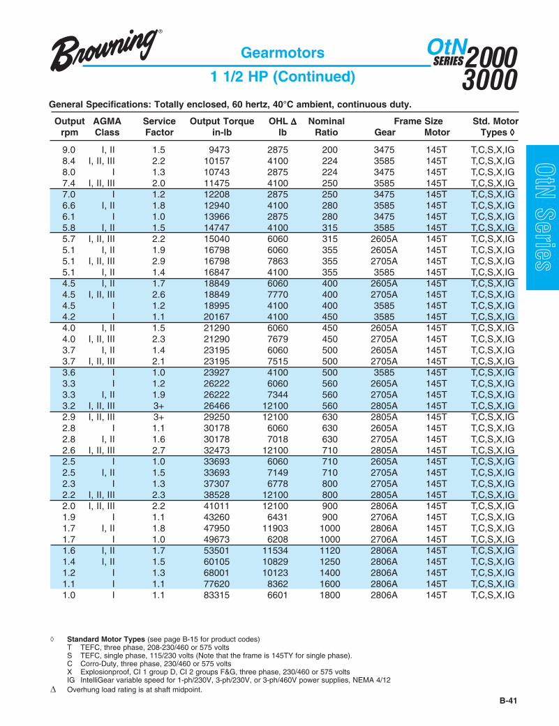
B-41
20003000
SERIESOtN
OtN Series
General Specifications: Totally enclosed, 60 hertz, 40°C ambient, continuous duty.
Gearmotors
1 1/2 HP (Continued)
Output AGMA Service Output Torque OHL ΔΔΔΔΔ Nominal Frame Size Std. Motorrpm Class Factor in-lb lb Ratio Gear Motor Types ◊◊◊◊◊
◊ Standard Motor Types (see page B-15 for product codes)T TEFC, three phase, 208-230/460 or 575 voltsS TEFC, single phase, 115/230 volts (Note that the frame is 145TY for single phase).C Corro-Duty, three phase, 230/460 or 575 voltsX Explosionproof, CI 1 group D, CI 2 groups F&G, three phase, 230/460 or 575 voltsIG IntelliGear variable speed for 1-ph/230V, 3-ph/230V, or 3-ph/460V power supplies, NEMA 4/12
Δ Overhung load rating is at shaft midpoint.
9.0 I, II 1.5 9473 2875 200 3475 145T T,C,S,X,IG8.4 I, II, III 2.2 10157 4100 224 3585 145T T,C,S,X,IG8.0 I 1.3 10743 2875 224 3475 145T T,C,S,X,IG7.4 I, II, III 2.0 11475 4100 250 3585 145T T,C,S,X,IG7.0 I 1.2 12208 2875 250 3475 145T T,C,S,X,IG6.6 I, II 1.8 12940 4100 280 3585 145T T,C,S,X,IG6.1 I 1.0 13966 2875 280 3475 145T T,C,S,X,IG5.8 I, II 1.5 14747 4100 315 3585 145T T,C,S,X,IG5.7 I, II, III 2.2 15040 6060 315 2605A 145T T,C,S,X,IG5.1 I, II 1.9 16798 6060 355 2605A 145T T,C,S,X,IG5.1 I, II, III 2.9 16798 7863 355 2705A 145T T,C,S,X,IG5.1 I, II 1.4 16847 4100 355 3585 145T T,C,S,X,IG4.5 I, II 1.7 18849 6060 400 2605A 145T T,C,S,X,IG4.5 I, II, III 2.6 18849 7770 400 2705A 145T T,C,S,X,IG4.5 I 1.2 18995 4100 400 3585 145T T,C,S,X,IG4.2 I 1.1 20167 4100 450 3585 145T T,C,S,X,IG4.0 I, II 1.5 21290 6060 450 2605A 145T T,C,S,X,IG4.0 I, II, III 2.3 21290 7679 450 2705A 145T T,C,S,X,IG3.7 I, II 1.4 23195 6060 500 2605A 145T T,C,S,X,IG3.7 I, II, III 2.1 23195 7515 500 2705A 145T T,C,S,X,IG3.6 I 1.0 23927 4100 500 3585 145T T,C,S,X,IG3.3 I 1.2 26222 6060 560 2605A 145T T,C,S,X,IG3.3 I, II 1.9 26222 7344 560 2705A 145T T,C,S,X,IG3.2 I, II, III 3+ 26466 12100 560 2805A 145T T,C,S,X,IG2.9 I, II, III 3+ 29250 12100 630 2805A 145T T,C,S,X,IG2.8 I 1.1 30178 6060 630 2605A 145T T,C,S,X,IG2.8 I, II 1.6 30178 7018 630 2705A 145T T,C,S,X,IG2.6 I, II, III 2.7 32473 12100 710 2805A 145T T,C,S,X,IG2.5 I 1.0 33693 6060 710 2605A 145T T,C,S,X,IG2.5 I, II 1.5 33693 7149 710 2705A 145T T,C,S,X,IG2.3 I 1.3 37307 6778 800 2705A 145T T,C,S,X,IG2.2 I, II, III 2.3 38528 12100 800 2805A 145T T,C,S,X,IG2.0 I, II, III 2.2 41011 12100 900 2806A 145T T,C,S,X,IG1.9 I 1.1 43260 6431 900 2706A 145T T,C,S,X,IG1.7 I, II 1.8 47950 11903 1000 2806A 145T T,C,S,X,IG1.7 I 1.0 49673 6208 1000 2706A 145T T,C,S,X,IG1.6 I, II 1.7 53501 11534 1120 2806A 145T T,C,S,X,IG1.4 I, II 1.5 60105 10829 1250 2806A 145T T,C,S,X,IG1.2 I 1.3 68001 10123 1400 2806A 145T T,C,S,X,IG1.1 I 1.1 77620 8362 1600 2806A 145T T,C,S,X,IG1.0 I 1.1 83315 6601 1800 2806A 145T T,C,S,X,IG
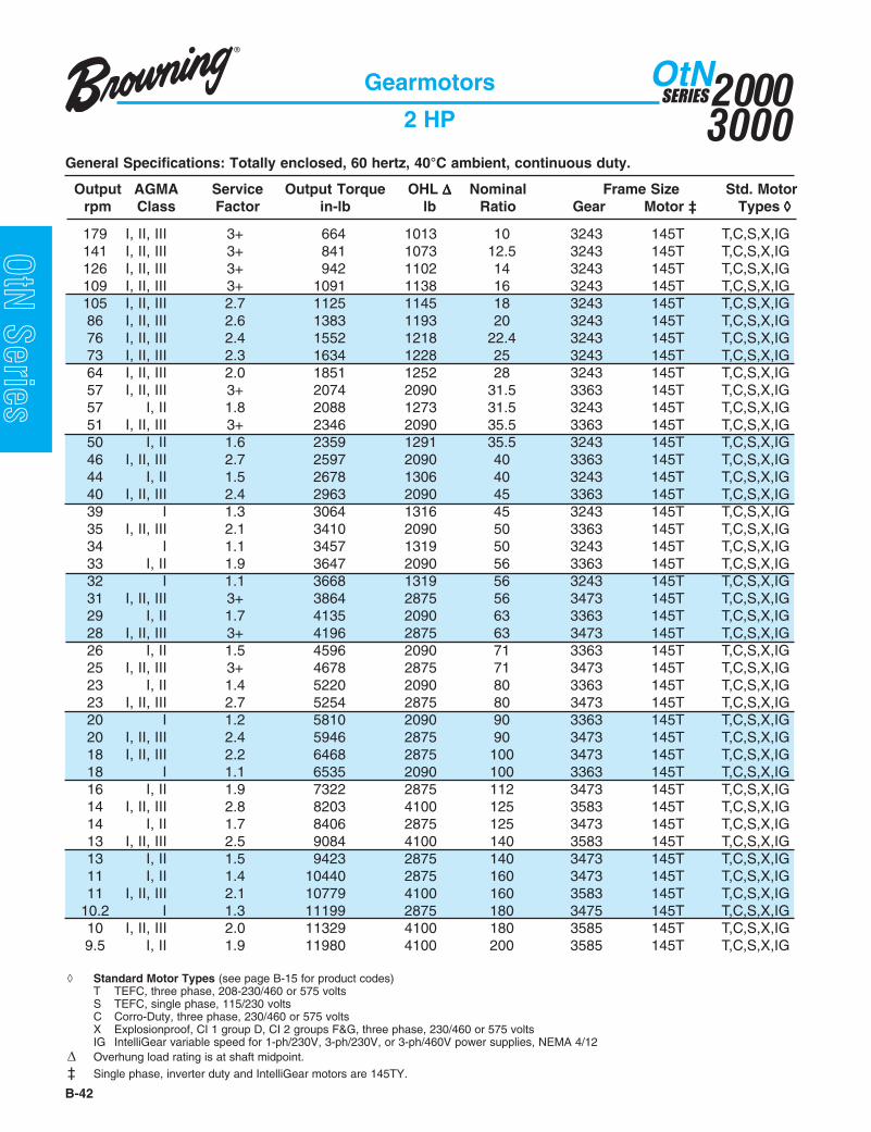
20003000
SERIESOtN
B-42
OtN Series
General Specifications: Totally enclosed, 60 hertz, 40°C ambient, continuous duty.
Gearmotors
2 HP
Output AGMA Service Output Torque OHL ΔΔΔΔΔ Nominal Frame Size Std. Motorrpm Class Factor in-lb lb Ratio Gear Motor ‡ Types ◊◊◊◊◊
179 I, II, III 3+ 664 1013 10 3243 145T T,C,S,X,IG141 I, II, III 3+ 841 1073 12.5 3243 145T T,C,S,X,IG126 I, II, III 3+ 942 1102 14 3243 145T T,C,S,X,IG109 I, II, III 3+ 1091 1138 16 3243 145T T,C,S,X,IG105 I, II, III 2.7 1125 1145 18 3243 145T T,C,S,X,IG86 I, II, III 2.6 1383 1193 20 3243 145T T,C,S,X,IG76 I, II, III 2.4 1552 1218 22.4 3243 145T T,C,S,X,IG73 I, II, III 2.3 1634 1228 25 3243 145T T,C,S,X,IG64 I, II, III 2.0 1851 1252 28 3243 145T T,C,S,X,IG57 I, II, III 3+ 2074 2090 31.5 3363 145T T,C,S,X,IG57 I, II 1.8 2088 1273 31.5 3243 145T T,C,S,X,IG51 I, II, III 3+ 2346 2090 35.5 3363 145T T,C,S,X,IG50 I, II 1.6 2359 1291 35.5 3243 145T T,C,S,X,IG46 I, II, III 2.7 2597 2090 40 3363 145T T,C,S,X,IG44 I, II 1.5 2678 1306 40 3243 145T T,C,S,X,IG40 I, II, III 2.4 2963 2090 45 3363 145T T,C,S,X,IG39 I 1.3 3064 1316 45 3243 145T T,C,S,X,IG35 I, II, III 2.1 3410 2090 50 3363 145T T,C,S,X,IG34 I 1.1 3457 1319 50 3243 145T T,C,S,X,IG33 I, II 1.9 3647 2090 56 3363 145T T,C,S,X,IG32 I 1.1 3668 1319 56 3243 145T T,C,S,X,IG31 I, II, III 3+ 3864 2875 56 3473 145T T,C,S,X,IG29 I, II 1.7 4135 2090 63 3363 145T T,C,S,X,IG28 I, II, III 3+ 4196 2875 63 3473 145T T,C,S,X,IG26 I, II 1.5 4596 2090 71 3363 145T T,C,S,X,IG25 I, II, III 3+ 4678 2875 71 3473 145T T,C,S,X,IG23 I, II 1.4 5220 2090 80 3363 145T T,C,S,X,IG23 I, II, III 2.7 5254 2875 80 3473 145T T,C,S,X,IG20 I 1.2 5810 2090 90 3363 145T T,C,S,X,IG20 I, II, III 2.4 5946 2875 90 3473 145T T,C,S,X,IG18 I, II, III 2.2 6468 2875 100 3473 145T T,C,S,X,IG18 I 1.1 6535 2090 100 3363 145T T,C,S,X,IG16 I, II 1.9 7322 2875 112 3473 145T T,C,S,X,IG14 I, II, III 2.8 8203 4100 125 3583 145T T,C,S,X,IG14 I, II 1.7 8406 2875 125 3473 145T T,C,S,X,IG13 I, II, III 2.5 9084 4100 140 3583 145T T,C,S,X,IG13 I, II 1.5 9423 2875 140 3473 145T T,C,S,X,IG11 I, II 1.4 10440 2875 160 3473 145T T,C,S,X,IG11 I, II, III 2.1 10779 4100 160 3583 145T T,C,S,X,IG
10.2 I 1.3 11199 2875 180 3475 145T T,C,S,X,IG10 I, II, III 2.0 11329 4100 180 3585 145T T,C,S,X,IG9.5 I, II 1.9 11980 4100 200 3585 145T T,C,S,X,IG
◊ Standard Motor Types (see page B-15 for product codes)T TEFC, three phase, 208-230/460 or 575 voltsS TEFC, single phase, 115/230 voltsC Corro-Duty, three phase, 230/460 or 575 voltsX Explosionproof, CI 1 group D, CI 2 groups F&G, three phase, 230/460 or 575 voltsIG IntelliGear variable speed for 1-ph/230V, 3-ph/230V, or 3-ph/460V power supplies, NEMA 4/12
Δ Overhung load rating is at shaft midpoint.
‡ Single phase, inverter duty and IntelliGear motors are 145TY.

B-43
20003000
SERIESOtN
OtN Series
General Specifications: Totally enclosed, 60 hertz, 40°C ambient, continuous duty.
Gearmotors
2 HP (Continued)
Output AGMA Service Output Torque OHL ΔΔΔΔΔ Nominal Frame Size Std. Motorrpm Class Factor in-lb lb Ratio Gear Motor ‡ Types ◊◊◊◊◊
◊ Standard Motor Types (see page B-15 for product codes)T TEFC, three phase, 208-230/460 or 575 voltsS TEFC, single phase, 115/230 voltsC Corro-Duty, three phase, 230/460 or 575 voltsX Explosionproof, CI 1 group D, CI 2 groups F&G, three phase, 230/460 or 575 voltsIG IntelliGear variable speed for 1-ph/230V, 3-ph/230V, or 3-ph/460V power supplies, NEMA 4/12
Δ Overhung load rating is at shaft midpoint.
‡ Single phase, inverter duty and IntelliGear motors are 145TY.
9.0 I 1.1 12631 2875 200 3475 145T T,C,S,X,IG8.4 I, II 1.7 13543 4100 224 3585 145T T,C,S,X,IG8.0 I 1.0 14324 2875 224 3475 145T T,C,S,X,IG7.4 I, II 1.5 15301 4100 250 3585 145T T,C,S,X,IG6.9 I, II, III 2.0 16408 6060 250 2605A 145T T,C,S,X,IG6.9 I, II, III 3+ 16408 7902 250 2705A 145T T,C,S,X,IG6.6 I 1.3 17254 4100 280 3585 145T T,C,S,X,IG6.2 I, II 1.8 18491 6060 280 2605A 145T T,C,S,X,IG6.2 I, II, III 2.6 18491 7829 280 2705A 145T T,C,S,X,IG5.8 I 1.2 19663 4100 315 3585 145T T,C,S,X,IG5.7 I, II 1.6 20054 6060 315 2605A 145T T,C,S,X,IG5.7 I, II, III 2.4 20054 7733 315 2705A 145T T,C,S,X,IG5.1 I, II 1.4 22398 6060 355 2605A 145T T,C,S,X,IG5.1 I, II, III 2.2 22398 7599 355 2705A 145T T,C,S,X,IG5.1 I 1.0 22463 4100 355 3585 145T T,C,S,X,IG4.5 I 1.3 25132 6060 400 2605A 145T T,C,S,X,IG4.5 I, II 1.9 25132 7426 400 2705A 145T T,C,S,X,IG4.4 I, II, III 3+ 26044 12100 400 2805A 145T T,C,S,X,IG4.0 I 1.1 28388 6060 450 2605A 145T T,C,S,X,IG4.0 I, II 1.7 28388 7256 450 2705A 145T T,C,S,X,IG3.7 I 1.0 30927 6060 500 2605A 145T T,C,S,X,IG3.7 I, II 1.6 30927 6944 500 2705A 145T T,C,S,X,IG3.5 I, II, III 2.7 32555 12100 500 2805A 145T T,C,S,X,IG3.3 I, II 1.4 34964 6611 560 2705A 145T T,C,S,X,IG3.2 I, II, III 2.5 35289 12100 560 2805A 145T T,C,S,X,IG2.9 I, II, III 2.3 39000 12100 630 2805A 145T T,C,S,X,IG2.8 I 1.2 40237 5949 630 2705A 145T T,C,S,X,IG2.6 I, II, III 2.0 43298 12095 710 2805A 145T T,C,S,X,IG2.5 I 1.1 44925 6219 710 2705A 145T T,C,S,X,IG2.3 I 1.0 49743 5986 800 2705A 145T T,C,S,X,IG2.2 I, II 1.7 51371 11774 800 2805A 145T T,C,S,X,IG2.0 I, II 1.6 54682 11109 900 2806A 145T T,C,S,X,IG1.7 I, II 1.4 63934 10356 1000 2806A 145T T,C,S,X,IG1.6 I 1.2 71335 9603 1120 2806A 145T T,C,S,X,IG1.4 I 1.1 80140 8980 1250 2806A 145T T,C,S,X,IG1.2 I 1.0 90668 8357 1400 2806A 145T T,C,S,X,IG

20003000
SERIESOtN
B-44
OtN Series
General Specifications: Totally enclosed, 60 hertz, 40°C ambient, continuous duty.
Gearmotors
2 1/2 HP
Output AGMA Service Output Torque OHL ΔΔΔΔΔ Nominal Frame Size Std. Motorrpm Class Factor in-lb lb Ratio Gear Motor Types ◊◊◊◊◊
179 I, II, III 3+ 830 982 10 3243 145TY T, C141 I, II, III 2.8 1051 1033 12.5 3243 145TY T, C126 I, II, III 2.5 1178 1057 14 3243 145TY T, C109 I, II, III 2.4 1364 1086 16 3243 145TY T, C105 I, II, III 2.1 1407 1092 18 3243 145TY T, C86 I, II, III 2.0 1729 1127 20 3243 145TY T, C76 I, II 1.9 1941 1144 22.4 3243 145TY T, C75 I, II, III 3+ 1974 2090 22.4 3363 145TY T, C73 I, II 1.8 2042 1151 25 3243 145TY T, C72 I, II, III 3+ 2059 2090 25 3363 145TY T, C64 I, II 1.6 2313 1165 28 3243 145TY T, C61 I, II, III 3+ 2432 2090 28 3363 145TY T, C57 I, II, III 2.8 2593 2090 31.5 3363 145TY T, C57 I, II 1.5 2610 1174 31.5 3243 145TY T, C51 I, II, III 2.4 2932 2090 35.5 3363 145TY T, C50 I 1.3 2949 1179 35.5 3243 145TY T, C46 I, II, III 2.1 3246 2090 40 3363 145TY T, C44 I 1.2 3347 1179 40 3243 145TY T, C40 I, II 1.9 3703 2090 45 3363 145TY T, C40 I, II, III 3+ 3737 2875 45 3473 145TY T, C39 I 1.0 3830 1171 45 3243 145TY T, C35 I, II 1.6 4263 2090 50 3363 145TY T, C35 I, II, III 3+ 4288 2875 50 3473 145TY T, C33 I, II 1.5 4559 2090 56 3363 145TY T, C31 I, II, III 2.8 4830 2875 56 3473 145TY T, C29 I, II 1.4 5169 2090 63 3363 145TY T, C28 I, II, III 2.6 5246 2875 63 3473 145TY T, C26 I 1.2 5746 2090 71 3363 145TY T, C25 I, II, III 2.4 5847 2875 71 3473 145TY T, C23 I 1.1 6525 2090 80 3363 145TY T, C23 I, II, III 2.1 6568 2875 80 3473 145TY T, C20 I 1.0 7262 2090 90 3363 145TY T, C20 I, II 1.9 7432 2875 90 3473 145TY T, C18 I, II 1.7 8084 2875 100 3473 145TY T, C17 I, II, III 2.7 8559 4100 100 3583 145TY T, C16 I, II 1.6 9152 2875 112 3473 145TY T, C16 I, II, III 2.5 9237 4100 112 3583 145TY T, C14 I, II, III 2.2 10254 4100 125 3583 145TY T, C14 I, II 1.4 10508 2875 125 3473 145TY T, C13 I, II, III 2.0 11355 4100 140 3583 145TY T, C
◊ Standard Motor Types (see page B-15 for product codes)T TEFC, three phase, 208-230/460 or 575 voltsC Corro-Duty, three phase, 230/460 or 575 volts
Δ Overhung load rating is at shaft midpoint.

B-45
20003000
SERIESOtN
OtN Series
General Specifications: Totally enclosed, 60 hertz, 40°C ambient, continuous duty.
Gearmotors
2 1/2 HP (Continued)
Output AGMA Service Output Torque OHL ΔΔΔΔΔ Nominal Frame Size Std. Motorrpm Class Factor in-lb lb Ratio Gear Motor Types ◊◊◊◊◊
13 I 1.2 11779 2875 140 3473 145TY T, C11 I 1.1 13050 2875 160 3473 145TY T, C11 I, II, III 2.5 12753 6060 160 2605A 145TY T, C11 I, II 1.7 13474 4100 160 3583 145TY T, C
10.2 I 1.0 13998 2875 180 3475 145TY T, C10 I, II, III 2.3 14080 6060 180 2605A 145TY T, C10 I, II 1.6 14161 4100 180 3585 145TY T, C9.5 I, II 1.5 14975 4100 200 3585 145TY T, C8.8 I, II, III 2.0 16196 6060 200 2605A 145TY T, C8.8 I, II, III 3+ 16196 7895 200 2705A 145TY T, C8.4 I 1.3 16928 4100 224 3585 145TY T, C8.0 I, II 1.8 17824 6060 224 2605A 145TY T, C8.0 I, II, III 2.7 17824 7830 224 2705A 145TY T, C7.4 I 1.2 19126 4100 250 3585 145TY T, C6.9 I, II, III 2.4 20509 7735 250 2705A 145TY T, C6.6 I 1.1 21567 4100 280 3585 145TY T, C6.2 I, II 1.4 23114 6060 280 2605A 145TY T, C6.2 I, II, III 2.1 23114 7619 280 2705A 145TY T, C5.7 I, II, III 2.0 25067 7463 315 2705A 145TY T, C5.6 I, II, III 3+ 25230 12100 315 2805A 145TY T, C5.1 I 1.2 27997 6060 355 2605A 145TY T, C5.1 I, II 1.8 27997 7246 355 2705A 145TY T, C5.0 I, II, III 3+ 28567 12100 355 2805A 145TY T, C4.5 I 1.0 31415 5982 400 2605A 145TY T, C4.5 I, II 1.6 31415 6960 400 2705A 145TY T, C4.4 I, II, III 2.7 32555 12100 400 2805A 145TY T, C4.1 I, II, III 2.5 34996 12100 450 2805A 145TY T, C4.0 I, II 1.4 35484 6674 450 2705A 145TY T, C3.7 I 1.3 38659 6133 500 2705A 145TY T, C3.5 I, II, III 2.2 40693 12100 500 2805A 145TY T, C3.3 I 1.1 43705 5528 560 2705A 145TY T, C3.2 I, II, III 2.0 44111 12022 560 2805A 145TY T, C2.9 I, II 1.8 48750 11673 630 2805A 145TY T, C2.8 I 1.0 50297 5295 630 2705A 145TY T, C2.6 I, II 1.6 54122 11145 710 2805A 145TY T, C2.2 I, II 1.4 64214 10595 800 2805A 145TY T, C2.0 I 1.3 68353 9406 900 2806A 145TY T, C1.7 I 1.1 79918 8773 1000 2806A 145TY T, C1.6 I 1.0 89170 8140 1120 2806A 145TY T, C
◊ Standard Motor Types (see page B-15 for product codes)T TEFC, three phase, 208-230/460 or 575 voltsC Corro-Duty, three phase, 230/460 or 575 volts
Δ Overhung load rating is at shaft midpoint.

20003000
SERIESOtN
B-46
OtN Series
General Specifications: Totally enclosed, 60 hertz, 40°C ambient, continuous duty.
Gearmotors
3 HP
Output AGMA Service Output Torque OHL ΔΔΔΔΔ Nominal Frame Size Std. Motorrpm Class Factor in-lb lb Ratio Gear Motor Types ◊◊◊◊◊
179 I, II, III 2.5 997 951 10 3243 182T T,C,S,X,IG141 I, II, III 2.3 1261 993 12.5 3243 182T T,C,S,X,IG126 I, II, III 2.1 1414 1012 14 3243 182T T,C,S,X,IG109 I, II, III 2.0 1637 1034 16 3243 182T T,C,S,X,IG105 I, II 1.8 1688 1038 18 3243 182T T,C,S,X,IG94 I, II, III 3+ 1891 2090 18 3363 182T T,C,S,X,IG86 I, II, III 3+ 2064 2090 20 3363 182T T,C,S,X,IG86 I, II 1.7 2074 1062 20 3243 182T T,C,S,X,IG76 I, II 1.6 2329 1071 22.4 3243 182T T,C,S,X,IG75 I, II, III 2.9 2369 2090 22.4 3363 182T T,C,S,X,IG73 I, II 1.5 2451 1074 25 3243 182T T,C,S,X,IG72 I, II, III 2.8 2471 2090 25 3363 182T T,C,S,X,IG64 I, II 1.4 2776 1077 28 3243 182T T,C,S,X,IG61 I, II, III 2.5 2919 2090 28 3363 182T T,C,S,X,IG57 I, II, III 2.3 3112 2090 31.5 3363 182T T,C,S,X,IG57 I 1.2 3132 1075 31.5 3243 182T T,C,S,X,IG51 I, II, III 2.0 3518 2090 35.5 3363 182T T,C,S,X,IG50 I 1.1 3539 1068 35.5 3243 182T T,C,S,X,IG46 I, II 1.8 3895 2090 40 3363 182T T,C,S,X,IG44 I 1.0 4017 1052 40 3243 182T T,C,S,X,IG44 I, II, III 3+ 4057 2875 40 3473 182T T,C,S,X,IG40 I, II 1.6 4444 2090 45 3363 182T T,C,S,X,IG40 I, II, III 3+ 4485 2875 45 3473 182T T,C,S,X,IG35 I, II 1.4 5115 2090 50 3363 182T T,C,S,X,IG35 I, II, III 2.6 5146 2875 50 3473 182T T,C,S,X,IG33 I 1.3 5471 2090 56 3363 182T T,C,S,X,IG31 I, II, III 2.4 5796 2875 56 3473 182T T,C,S,X,IG29 I 1.1 6203 2090 63 3363 182T T,C,S,X,IG28 I, II, III 2.2 6295 2875 63 3473 182T T,C,S,X,IG26 I 1.0 6895 2090 71 3363 182T T,C,S,X,IG25 I, II, III 2.0 7017 2875 71 3473 182T T,C,S,X,IG23 I, II 1.8 7881 2875 80 3473 182T T,C,S,X,IG22 I, II, III 2.8 8196 4100 80 3583 182T T,C,S,X,IG20 I, II, III 2.6 8796 4100 90 3583 182T T,C,S,X,IG20 I, II 1.6 8918 2875 90 3473 182T T,C,S,X,IG18 I, II 1.5 9701 2875 100 3473 182T T,C,S,X,IG17 I, II, III 2.2 10271 4100 100 3583 182T T,C,S,X,IG16 I 1.3 10983 2875 112 3473 182T T,C,S,X,IG16 I, II, III 2.1 11084 4100 112 3583 182T T,C,S,X,IG14 I, II 1.9 12305 4100 125 3583 182T T,C,S,X,IG14 I 1.1 12610 2875 125 3473 182T T,C,S,X,IG
◊ Standard Motor Types (see page B-15 for product codes)T TEFC, three phase, 208-230/460 or 575 voltsS TEFC, single phase, 230 volts (Note that single phase motor has 184T frame.)C Corro-Duty, three phase, 230/460 or 575 voltsX Explosionproof, CI 1 group D, CI 2 groups F&G, three phase, 230/460 or 575 voltsIG IntelliGear variable speed for 3-ph/230V or 3-ph/460V power supplies, NEMA 4/12
Δ Overhung load rating is at shaft midpoint.

B-47
20003000
SERIESOtN
OtN Series
General Specifications: Totally enclosed, 60 hertz, 40°C ambient, continuous duty.
Gearmotors
3 HP (Continued)
Output AGMA Service Output Torque OHL ΔΔΔΔΔ Nominal Frame Size Std. Motorrpm Class Factor in-lb lb Ratio Gear Motor Types ◊◊◊◊◊
13 I, II 1.7 13627 4100 140 3583 182T T,C,S,X,IG13 I 1.0 14135 2875 140 3473 182T T,C,S,X,IG12 I, II, III 2.3 13868 6060 140 2605A 182T T,C,S,X,IG11 I, II, III 2.1 15333 6060 160 2605A 182T T,C,S,X,IG11 I, II 1.4 16169 4100 160 3583 182T T,C,S,X,IG10 I, II 1.9 16896 6060 180 2605A 182T T,C,S,X,IG10 I, II, III 2.9 16896 7870 180 2705A 182T T,C,S,X,IG10 I 1.3 16993 4100 180 3585 182T T,C,S,X,IG10 I 1.3 17970 4100 200 3585 182T T,C,S,X,IG8.8 I, II 1.5 19435 6060 200 2605A 182T T,C,S,X,IG8.8 I, II, III 2.5 19435 7762 200 2705A 182T T,C,S,X,IG8.4 I 1.1 20314 4100 224 3585 182T T,C,S,X,IG8.0 I, II 1.5 21388 6060 224 2605A 182T T,C,S,X,IG8.0 I, II, III 2.3 21388 7666 224 2705A 182T T,C,S,X,IG7.4 I 1.0 22951 4100 250 3585 182T T,C,S,X,IG6.9 I, II, III 2.0 24611 7526 250 2705A 182T T,C,S,X,IG6.3 I, II, III 3+ 26955 12100 280 2805A 182T T,C,S,X,IG6.2 I 1.2 27737 6060 280 2605A 182T T,C,S,X,IG6.2 I, II 1.8 27737 7353 280 2705A 182T T,C,S,X,IG5.7 I 1.1 30080 6060 315 2605A 182T T,C,S,X,IG5.7 I, II 1.6 30080 7120 315 2705A 182T T,C,S,X,IG5.6 I, II, III 2.9 30276 12100 315 2805A 182T T,C,S,X,IG5.1 I 1.0 33596 5872 355 2605A 182T T,C,S,X,IG5.1 I, II 1.5 33596 6788 355 2705A 182T T,C,S,X,IG5.0 I, II, III 2.6 34280 12100 355 2805A 182T T,C,S,X,IG4.5 I 1.3 37698 6343 400 2705A 182T T,C,S,X,IG4.4 I, II, III 2.3 39065 12100 400 2805A 182T T,C,S,X,IG4.1 I, II, III 2.1 41995 12100 450 2805A 182T T,C,S,X,IG4.0 I 1.2 42581 5884 450 2705A 182T T,C,S,X,IG3.7 I 1.1 46390 4965 500 2705A 182T T,C,S,X,IG3.5 I, II 1.8 48832 11922 500 2805A 182T T,C,S,X,IG3.2 I, II 1.7 52934 11247 560 2805A 182T T,C,S,X,IG2.9 I, II 1.5 58501 10705 630 2805A 182T T,C,S,X,IG2.6 I, II 1.4 64946 9862 710 2805A 182T T,C,S,X,IG2.2 I 1.2 77057 8945 800 2805A 182T T,C,S,X,IG2.0 I 1.1 82024 6767 900 2806A 182T T,C,S,X,IG
◊ Standard Motor Types (see page B-15 for product codes)T TEFC, three phase, 208-230/460 or 575 voltsS TEFC, single phase, 230 volts (Note that single phase motor has 184T frame.)C Corro-Duty, three phase, 230/460 or 575 voltsX Explosionproof, CI 1 group D, CI 2 groups F&G, three phase, 230/460 or 575 voltsIG IntelliGear variable speed for 3-ph/230V or 3-ph/460V power supplies, NEMA 4/12
Δ Overhung load rating is at shaft midpoint.

20003000
SERIESOtN
B-48
OtN Series
General Specifications: Totally enclosed, 60 hertz, 40°C ambient, continuous duty.
Gearmotors
5 HP
Output AGMA Service Output Torque OHL ΔΔΔΔΔ Nominal Frame Size Std. Motorrpm Class Factor in-lb lb Ratio Gear Motor Types ◊◊◊◊◊
179 I, II, III 3+ 1658 1771 10 3363 184T T,C,S,X,IG179 I, II 1.5 1661 825 10 3243 184T T,C,S,X,IG142 I, II, III 2.7 2085 1866 12.5 3363 184T T,C,S,X,IG141 I, II 1.4 2102 834 12.5 3243 184T T,C,S,X,IG126 I 1.3 2356 834 14 3243 184T T,C,S,X,IG118 I, II, III 2.4 2508 1941 14 3363 184T T,C,S,X,IG109 I 1.2 2729 827 16 3243 184T T,C,S,X,IG109 I, II, III 2.3 2729 1973 16 3363 184T T,C,S,X,IG105 I 1.1 2813 825 18 3243 184T T,C,S,X,IG94 I, II, III 2.0 3152 2026 18 3363 184T T,C,S,X,IG86 I, II, III 2.0 3441 2057 20 3363 184T T,C,S,X,IG86 I 1.0 3457 800 20 3243 184T T,C,S,X,IG82 I, II, III 3+ 3610 2875 22.4 3473 184T T,C,S,X,IG75 I, II 1.7 3949 2090 22.4 3363 184T T,C,S,X,IG72 I, II 1.7 4118 2090 25 3363 184T T,C,S,X,IG71 I, II, III 3+ 4203 2875 25 3473 184T T,C,S,X,IG61 I, II, III 2.7 4847 2875 28 3473 184T T,C,S,X,IG61 I, II 1.5 4864 2090 28 3363 184T T,C,S,X,IG57 I, II 1.4 5186 2090 31.5 3363 184T T,C,S,X,IG56 I, II, III 2.5 5339 2875 31.5 3473 184T T,C,S,X,IG51 I 1.2 5864 2090 35.5 3363 184T T,C,S,X,IG50 I, II, III 2.3 5898 2875 35.5 3473 184T T,C,S,X,IG46 I 1.1 6491 2090 40 3363 184T T,C,S,X,IG44 I, II, III 2.0 6762 2875 40 3473 184T T,C,S,X,IG41 I, II, III 3+ 7220 4100 45 3583 184T T,C,S,X,IG40 I, II 1.8 7474 2875 45 3473 184T T,C,S,X,IG35 I, II, III 2.7 8440 4100 50 3583 184T T,C,S,X,IG35 I, II 1.6 8576 2875 50 3473 184T T,C,S,X,IG32 I, II, III 2.4 9406 4100 56 3583 184T T,C,S,X,IG31 I, II 1.4 9661 2875 56 3473 184T T,C,S,X,IG28 I 1.3 10491 2875 63 3473 184T T,C,S,X,IG28 I, II, III 2.1 10576 4100 63 3583 184T T,C,S,X,IG25 I 1.2 11694 2875 71 3473 184T T,C,S,X,IG25 I, II, III 2.5 11864 6060 71 2603 184T T,C,S,X,IG25 I, II 1.9 11966 4100 71 3583 184T T,C,S,X,IG23 I 1.1 13135 2875 80 3473 184T T,C,S,X,IG22 I, II, III 2.2 13406 6060 80 2603 184T T,C,S,X,IG22 I, II 1.7 13660 4100 80 3583 184T T,C,S,X,IG20 I, II 1.6 14660 4100 90 3583 184T T,C,S,X,IG20 I, II, III 2.0 14762 6060 90 2603 184T T,C,S,X,IG
◊ Standard Motor Types (see page B-15 for product codes)T TEFC, three phase, 208-230/460 or 575 voltsS TEFC, single phase, 230 voltsC Corro-Duty, three phase, 230/460 or 575 voltsX Explosionproof, CI 1 group D, CI 2 groups F&G, three phase, 230/460 or 575 voltsIG IntelliGear variable speed for 3-ph/230V or 3-ph/460V power supplies, NEMA 4/12
Δ Overhung load rating is at shaft midpoint.

B-49
20003000
SERIESOtN
OtN Series
General Specifications: Totally enclosed, 60 hertz, 40°C ambient, continuous duty.
Gearmotors
5 HP (Continued)
Output AGMA Service Output Torque OHL ΔΔΔΔΔ Nominal Frame Size Std. Motorrpm Class Factor in-lb lb Ratio Gear Motor Types ◊◊◊◊◊
20 I 1.0 14864 2875 90 3473 184T T,C,S,X,IG18 I, II 1.8 16864 6060 100 2603 184T T,C,S,X,IG18 I, II, III 2.9 16864 7865 100 2703 184T T,C,S,X,IG17 I 1.3 17118 4100 100 3583 184T T,C,S,X,IG16 I 1.2 18474 4100 112 3583 184T T,C,S,X,IG15 I, II 1.5 20225 6060 80 2603 215T † T,C,X15 I, II, III 2.4 20225 7865 80 2703 215T † T,C,X14 I 1.1 20508 4100 125 3583 184T T,C,S,X,IG14 I, II 1.6 20021 6060 125 2605A 184T T,C,S,X,IG13 I, II, III 2.2 22270 7610 90 2703 215T † T,C,X13 I 1.0 22711 4100 140 3583 184T T,C,S,X,IG12 I, II 1.4 23114 6060 140 2605A 184T T,C,S,X,IG12 I, II, III 2.1 23114 7412 140 2705A 184T T,C,S,X,IG12 I, II, III 3+ 24741 12100 160 2805A 184T T,C,S,X,IG11 I 1.3 25555 6060 160 2605A 184T T,C,S,X,IG11 I, II 1.9 25555 7421 160 2705A 184T T,C,S,X,IG10 I, II, III 3+ 27509 12100 180 2805A 184T T,C,S,X,IG10 I 1.2 28160 6060 180 2605A 184T T,C,S,X,IG10 I, II 1.7 28160 7265 180 2705A 184T T,C,S,X,IG9.1 I, II, III 2.8 31252 12100 200 2805A 184T T,C,S,X,IG8.8 I 1.0 32392 6060 200 2605A 184T T,C,S,X,IG8.8 I, II 1.5 32392 6936 200 2705A 184T T,C,S,X,IG8.3 I, II, III 2.6 34508 12100 224 2805A 184T T,C,S,X,IG8.0 I, II 1.4 35647 6633 224 2705A 184T T,C,S,X,IG7.1 I, II, III 2.2 40205 12100 250 2805A 184T T,C,S,X,IG6.9 I 1.2 41019 6169 250 2705A 184T T,C,S,X,IG6.3 I, II, III 2.0 44925 12100 280 2805A 184T T,C,S,X,IG6.2 I 1.1 46228 5563 280 2705A 184T T,C,S,X,IG5.7 I 1.0 50134 5330 315 2705A 184T T,C,S,X,IG5.6 I, II 1.8 50460 11731 315 2805A 184T T,C,S,X,IG5.0 I, II 1.6 57133 11235 355 2805A 184T T,C,S,X,IG4.4 I, II 1.4 65109 10435 400 2805A 184T T,C,S,X,IG4.1 I 1.3 69992 9173 450 2805A 184T T,C,S,X,IG3.5 I 1.1 81386 8064 500 2805A 184T T,C,S,X,IG3.2 I 1.0 88223 7431 560 2805A 184T T,C,S,X,IG
◊ Standard Motor Types (see page B-15 for product codes)T TEFC, three phase, 208-230/460 or 575 voltsS TEFC, single phase, 230 voltsC Corro-Duty, three phase, 230/460 or 575 voltsX Explosionproof, CI 1 group D, CI 2 groups F&G, three phase, 230/460 or 575 voltsIG IntelliGear variable speed for 3-ph/230V or 3-ph/460V power supplies, NEMA 4/12
Δ Overhung load rating is at shaft midpoint.
† Denotes 6-pole (1200 rpm) motor.

20003000
SERIESOtN
B-50
OtN Series
General Specifications: Totally enclosed, 60 hertz, 40°C ambient, continuous duty.
Gearmotors
7 1/2 HP
Output AGMA Service Output Torque OHL ΔΔΔΔΔ Nominal Frame Size Std. Motorrpm Class Factor in-lb lb Ratio Gear Motor Types ◊◊◊◊◊
179 I, II, III 2.1 2486 1644 10 3363 213T T,C,X,IG142 I, II 1.8 3127 1707 12.5 3363 213T T,C,X,IG142 I, II, III 3+ 3127 2875 12.5 3473 213T T,C,X,IG118 I, II 1.6 3763 1750 14 3363 213T T,C,X,IG115 I, II, III 3+ 3864 2875 14 3473 213T T,C,X,IG113 I, II, III 3+ 3941 2875 16 3473 213T T,C,X,IG109 I, II 1.6 4093 1765 16 3363 213T T,C,X,IG100 I, II, III 2.6 4449 2875 18 3473 213T T,C,X,IG94 I 1.3 4729 1786 18 3363 213T T,C,X,IG87 I, II, III 2.4 5110 2875 20 3473 213T T,C,X,IG86 I 1.3 5161 1794 20 3363 213T T,C,X,IG82 I, II, III 2.1 5415 2875 22.4 3473 213T T,C,X,IG75 I 1.1 5923 1800 22.4 3363 213T T,C,X,IG72 I 1.1 6178 1799 25 3363 213T T,C,X,IG71 I, II, III 2.0 6305 2875 25 3473 213T T,C,X,IG65 I, II, III 3+ 6890 4100 28 3583 213T T,C,X,IG61 I, II 1.8 7271 2875 28 3473 213T T,C,X,IG61 I 1.0 7296 1785 28 3363 213T T,C,X,IG57 I, II, III 2.8 7754 4100 31.5 3583 213T T,C,X,IG56 I, II 1.7 8008 2875 31.5 3473 213T T,C,X,IG51 I, II, III 2.6 8644 4100 35.5 3583 213T T,C,X,IG50 I, II 1.5 8847 2875 35.5 3473 213T T,C,X,IG45 I, II, III 2.3 9813 4100 40 3583 213T T,C,X,IG44 I 1.3 10144 2875 40 3473 213T T,C,X,IG41 I, II, III 2.1 10830 4100 45 3583 213T T,C,X,IG40 I 1.2 11211 2875 45 3473 213T T,C,X,IG35 I, II 1.8 12660 4100 50 3583 213T T,C,X,IG35 I 1.0 12864 2875 50 3473 213T T,C,X,IG34 I, II, III 2.3 13067 6060 50 2603 213T T,C,X,IG32 I, II 1.6 14110 4100 56 3583 213T T,C,X,IG30 I, II, III 2.1 14618 6060 56 2603 213T T,C,X,IG28 I, II 1.4 15864 4100 63 3583 213T T,C,X,IG
◊ Standard Motor Types (see page B-15 for product codes)T TEFC, three phase, 208-230/460 or 575 voltsC Corro-Duty, three phase, 230/460 or 575 voltsX Explosionproof, CI 1 group D, CI 2 groups F&G, three phase, 230/460 or 575 voltsIG IntelliGear variable speed for 3-ph/460V power supplies, NEMA 4/12
Δ Overhung load rating is at shaft midpoint.

B-51
20003000
SERIESOtN
OtN Series
General Specifications: Totally enclosed, 60 hertz, 40°C ambient, continuous duty.
Gearmotors
7 1/2 HP (Continued)
Output AGMA Service Output Torque OHL ΔΔΔΔΔ Nominal Frame Size Std. Motorrpm Class Factor in-lb lb Ratio Gear Motor Types ◊◊◊◊◊
27 I, II, III 3+ 16499 7880 63 2703 213T T,C,X,IG25 I, II 1.7 17796 6060 71 2603 213T T,C,X,IG25 I, II, III 2.8 17796 7828 71 2703 213T T,C,X,IG25 I 1.3 17948 4100 71 3583 213T T,C,X,IG22 I, II 1.5 20109 6060 80 2603 213T T,C,X,IG22 I, II, III 2.4 20109 7724 80 2703 213T T,C,X,IG22 I 1.1 20491 4100 80 3583 213T T,C,X,IG20 I 1.0 21991 4100 90 3583 213T T,C,X,IG20 I, II 1.4 22143 6060 90 2603 213T T,C,X,IG20 I, II, III 2.2 22143 7001 90 2703 213T T,C,X,IG18 I 1.2 25296 6060 100 2603 213T T,C,X,IG18 I, II 1.9 25296 7440 100 2703 213T T,C,X,IG17 I, II, III 3+ 25957 12100 100 2803 213T T,C,X,IG14 I, II, III 3+ 29543 12100 125 2805A 213T T,C,X,IG14 I 1.1 30032 6060 125 2605A 213T T,C,X,IG12 I, II 1.4 34671 6815 140 2705A 213T T,C,X,IG12 I, II, III 2.4 37112 12100 160 2805A 213T T,C,X,IG11 I 1.3 38333 6330 160 2705A 213T T,C,X,IG10 I, II, III 2.1 41263 12100 180 2805A 213T T,C,X,IG10 I 1.2 42240 5907 180 2705A 213T T,C,X,IG9 I, II 1.9 46879 11964 200 2805A 213T T,C,X,IG9 I 1.0 48588 5674 200 2705A 213T T,C,X,IG8 I, II 1.7 51762 11374 224 2805A 213T T,C,X,IG7 I, II 1.5 60307 10821 250 2805A 213T T,C,X,IG6 I 1.3 67388 10059 280 2805A 213T T,C,X,IG6 I 1.2 75689 8819 315 2805A 213T T,C,X,IG5 I 1.0 85700 7220 355 2805A 213T T,C,X,IG
◊ Standard Motor Types (see page B-15 for product codes)T TEFC, three phase, 208-230/460 or 575 voltsC Corro-Duty, three phase, 230/460 or 575 voltsX Explosionproof, CI 1 group D, CI 2 groups F&G, three phase, 230/460 or 575 voltsIG IntelliGear variable speed for 3-ph/460V power supplies, NEMA 4/12
Δ Overhung load rating is at shaft midpoint.

20003000
SERIESOtN
B-52
OtN Series
General Specifications: Totally enclosed, 60 hertz, 40°C ambient, continuous duty.
Gearmotors
10 HP
Output AGMA Service Output Torque OHL ΔΔΔΔΔ Nominal Frame Size Std. Motorrpm Class Factor in-lb lb Ratio Gear Motor Types ◊◊◊◊◊
184 I, II, III 2.5 3224 2761 10 3473 215T T,C,X,IG179 I, II 1.6 3315 1518 10 3363 215T T,C,X,IG142 I 1.3 4169 1549 12.5 3363 215T T,C,X,IG142 I, II, III 2.3 4169 2875 12.5 3473 215T T,C,X,IG118 I 1.2 5017 1558 14 3363 215T T,C,X,IG115 I, II, III 2.2 5152 2875 14 3473 215T T,C,X,IG113 I, II, III 2.2 5254 2875 16 3473 215T T,C,X,IG109 I 1.2 5457 1557 16 3363 215T T,C,X,IG100 I, II, III 2.0 5932 2875 18 3473 215T T,C,X,IG94 I 1.0 6305 1546 18 3363 215T T,C,X,IG88 I, II, III 2.9 6779 4100 20 3583 215T T,C,X,IG87 I, II 1.8 6813 2875 20 3473 215T T,C,X,IG86 I 1.0 6881 1532 20 3363 215T T,C,X,IG82 I, II 1.6 7220 2875 22.4 3473 215T T,C,X,IG74 I, II, III 2.6 8000 4100 22.4 3583 215T T,C,X,IG72 I, II, III 2.6 8237 4100 25 3583 215T T,C,X,IG71 I, II 1.5 8406 2875 25 3473 215T T,C,X,IG65 I, II, III 2.3 9186 4100 28 3583 215T T,C,X,IG61 I 1.3 9694 2875 28 3473 215T T,C,X,IG57 I, II, III 2.1 10338 4100 31.5 3583 215T T,C,X,IG56 I 1.3 10677 2875 31.5 3473 215T T,C,X,IG51 I, II 1.9 11525 4100 35.5 3583 215T T,C,X,IG50 I 1.1 11796 2875 35.5 3473 215T T,C,X,IG48 I, II, III 2.4 12270 6060 35.5 2603 215T T,C,X,IG45 I, II 1.7 13084 4100 40 3583 215T T,C,X,IG44 I, II, III 2.2 13491 6060 40 2603 215T T,C,X,IG44 I 1.0 13525 2875 40 3473 215T T,C,X,IG41 I, II 1.6 14440 4100 45 3583 215T T,C,X,IG40 I, II, III 2.0 14881 6060 45 2603 215T T,C,X,IG35 I 1.3 16880 4100 50 3583 215T T,C,X,IG34 I, II 1.7 17423 6060 50 2603 215T T,C,X,IG34 I, II, III 2.8 17423 7843 50 2703 215T T,C,X,IG32 I 1.2 18812 4100 56 3583 215T T,C,X,IG30 I, II 1.5 19490 6060 56 2603 215T T,C,X,IG30 I, II, III 2.5 19490 7753 56 2703 215T T,C,X,IG28 I 1.1 21151 4100 63 3583 215T T,C,X,IG
◊ Standard Motor Types (see page B-15 for product codes)T TEFC, three phase, 208-230/460 or 575 voltsC Corro-Duty, three phase, 230/460 or 575 voltsX Explosionproof, CI 1 group D, CI 2 groups F&G, three phase, 230/460 or 575 voltsIG IntelliGear variable speed for 3-ph/460V power supplies, NEMA 4/12
Δ Overhung load rating is at shaft midpoint.
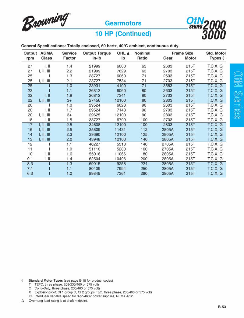
B-53
20003000
SERIESOtN
OtN Series
General Specifications: Totally enclosed, 60 hertz, 40°C ambient, continuous duty.
Gearmotors
10 HP (Continued)
Output AGMA Service Output Torque OHL ΔΔΔΔΔ Nominal Frame Size Std. Motorrpm Class Factor in-lb lb Ratio Gear Motor Types ◊◊◊◊◊
◊ Standard Motor Types (see page B-15 for product codes)T TEFC, three phase, 208-230/460 or 575 voltsC Corro-Duty, three phase, 230/460 or 575 voltsX Explosionproof, CI 1 group D, CI 2 groups F&G, three phase, 230/460 or 575 voltsIG IntelliGear variable speed for 3-ph/460V power supplies, NEMA 4/12
Δ Overhung load rating is at shaft midpoint.
27 I, II 1.4 21999 6060 63 2603 215T T,C,X,IG27 I, II, III 2.2 21999 7629 63 2703 215T T,C,X,IG25 I 1.3 23727 6060 71 2603 215T T,C,X,IG25 I, II, III 2.1 23727 7534 71 2703 215T T,C,X,IG25 I 1.0 23931 4100 71 3583 215T T,C,X,IG22 I 1.1 26812 6060 80 2603 215T T,C,X,IG22 I, II 1.8 26812 7341 80 2703 215T T,C,X,IG22 I, II, III 3+ 27456 12100 80 2803 215T T,C,X,IG20 I 1.0 29524 6023 90 2603 215T T,C,X,IG20 I, II 1.7 29524 7148 90 2703 215T T,C,X,IG20 I, II, III 3+ 29625 12100 90 2803 215T T,C,X,IG18 I, II 1.5 33727 6799 100 2703 215T T,C,X,IG17 I, II, III 2.5 34608 12100 100 2803 215T T,C,X,IG16 I, II, III 2.5 35809 11431 112 2805A 215T T,C,X,IG14 I, II, III 2.3 39390 12100 125 2805A 215T T,C,X,IG13 I, II, III 2.0 43948 12100 140 2805A 215T T,C,X,IG12 I 1.1 46227 5513 140 2705A 215T T,C,X,IG11 I 1.0 51110 5280 160 2705A 215T T,C,X,IG10 I, II 1.6 55016 11066 180 2805A 215T T,C,X,IG9.1 I, II 1.4 62504 10496 200 2805A 215T T,C,X,IG8.3 I 1.3 69015 9258 224 2805A 215T T,C,X,IG7.1 I 1.1 80409 7994 250 2805A 215T T,C,X,IG6.3 I 1.0 89849 7361 280 2805A 215T T,C,X,IG

20003000
SERIESOtN
B-54
OtN Series
General Specifications: Totally enclosed, 60 hertz, 40°C ambient, continuous duty.
Gearmotors
15 HP
Output AGMA Service Output Torque OHL ΔΔΔΔΔ Nominal Frame Size Std. Motorrpm Class Factor in-lb lb Ratio Gear Motor Types ◊◊◊◊◊
185 I, II, III 3+ 4815 3659 10 3583 254T T, C, X184 I, II 1.7 4835 2545 10 3473 254T T, C, X142 I, II 1.5 6254 2641 12.5 3473 254T T, C, X142 I, II, III 3+ 6254 3874 12.5 3583 254T T, C, X117 I, II, III 2.6 7576 4022 14 3583 254T T, C, X115 I, II 1.5 7728 2698 14 3473 254T T, C, X113 I, II 1.5 7881 2702 16 3473 254T T, C, X113 I, II, III 2.3 7881 4051 16 3583 254T T, C, X100 I 1.3 8898 2720 18 3473 254T T, C, X94 I, II, III 2.2 9508 4100 18 3583 254T T, C, X88 I, II, III 2.0 10169 4100 20 3583 254T T, C, X87 I 1.2 10220 2728 20 3473 254T T, C, X82 I 1.1 10830 2726 22.4 3473 254T T, C, X78 I, II, III 2.6 11440 6060 22.4 2603 254T T, C, X74 I, II 1.8 11999 4100 22.4 3583 254T T, C, X72 I, II 1.7 12355 4100 25 3583 254T T, C, X71 I 1.0 12609 2705 25 3473 254T T, C, X69 I, II, III 2.3 12965 6060 25 2603 254T T, C, X65 I, II 1.6 13779 4100 28 3583 254T T, C, X63 I, II, III 2.1 14084 6060 28 2603 254T T, C, X57 I, II 1.4 15508 4100 31.5 3583 254T T, C, X55 I, II 1.9 16067 6060 31.5 2603 254T T, C, X51 I 1.3 17287 4100 35.5 3583 254T T, C, X48 I, II 1.6 18406 6060 35.5 2603 254T T, C, X48 I, II, III 2.6 18406 7802 35.5 2703 254T T, C, X45 I 1.1 19626 4100 40 3583 254T T, C, X44 I, II 1.5 20236 6060 40 2603 254T T, C, X44 I, II, III 2.4 20236 7718 40 2703 254T T, C, X41 I 1.0 21660 4100 45 3583 254T T, C, X40 I 1.3 22321 6060 45 2603 254T T, C, X40 I, II, III 2.2 22321 7612 45 2703 254T T, C, X34 I, II, III 3+ 25829 12100 50 2803 254T T, C, X34 I 1.1 26134 6060 50 2603 254T T, C, X34 I, II 1.8 26134 7386 50 2703 254T T, C, X
◊ Standard Motor Types (see page B-15 for product codes)T TEFC, three phase, 208-230/460 or 575 voltsC Corro-Duty, three phase, 230/460 or 575 voltsX Explosionproof, CI 1 group D, CI 2 groups F&G, three phase, 230/460 or 575 volts
Δ Overhung load rating is at shaft midpoint.

B-55
20003000
SERIESOtN
OtN Series
General Specifications: Totally enclosed, 60 hertz, 40°C ambient, continuous duty.
Gearmotors
15 HP (Continued)
Output AGMA Service Output Torque OHL ΔΔΔΔΔ Nominal Frame Size Std. Motorrpm Class Factor in-lb lb Ratio Gear Motor Types ◊◊◊◊◊
30 I 1.0 29236 6060 56 2603 254T T, C, X30 I, II 1.6 29236 7170 56 2703 254T T, C, X27 I, II, III 2.6 32947 12100 63 2803 254T T, C, X27 I, II 1.5 32998 6864 63 2703 254T T, C, X25 I, II 1.4 35591 6622 71 2703 254T T, C, X25 I, II, III 2.4 35693 12100 71 2803 254T T, C, X22 I 1.2 40218 6117 80 2703 254T T, C, X22 I, II, III 2.1 41184 12100 80 2803 254T T, C, X20 I 1.1 44286 5578 90 2703 254T T, C, X20 I, II, III 2.0 44438 12100 90 2803 254T T, C, X17 I, II 1.7 51912 11787 100 2803 254T T, C, X16 I, II 1.7 53714 11431 112 2805A 254T T, C, X14 I, II 1.5 59086 10522 125 2805A 254T T, C, X13 I 1.3 65922 9916 140 2805A 254T T, C, X12 I 1.2 74223 8708 160 2805A 254T T, C, X10 I 1.1 82525 8075 180 2805A 254T T, C, X
◊ Standard Motor Types (see page B-15 for product codes)T TEFC, three phase, 208-230/460 or 575 voltsC Corro-Duty, three phase, 230/460 or 575 voltsX Explosionproof, CI 1 group D, CI 2 groups F&G, three phase, 230/460 or 575 volts
Δ Overhung load rating is at shaft midpoint.

20003000
SERIESOtN
B-56
OtN Series
General Specifications: Totally enclosed, 60 hertz, 40°C ambient, continuous duty.
Gearmotors
20 HP
Output AGMA Service Output Torque OHL ΔΔΔΔΔ Nominal Frame Size Std. Motorrpm Class Factor in-lb lb Ratio Gear Motor Types ◊◊◊◊◊
185 I, II, III 2.7 6420 3469 10 3583 256T T, C, X184 I 1.3 6447 2329 10 3473 256T T, C, X142 I 1.2 8339 2361 12.5 3473 256T T, C, X142 I, II, III 2.3 8339 3626 12.5 3583 256T T, C, X117 I, II 1.9 10101 3722 14 3583 256T T, C, X115 I 1.1 10304 2352 14 3473 256T T, C, X113 I 1.1 10508 2349 16 3473 256T T, C, X113 I, II 1.8 10508 3739 16 3583 256T T, C, X111 I, II, III 2.7 10643 6060 16 2603 256T T, C, X100 I 1.0 11864 2323 18 3473 256T T, C, X94 I, II 1.6 12677 3803 18 3583 256T T, C, X88 I, II, III 2.2 13491 6060 20 2603 256T T, C, X88 I, II 1.5 13559 3819 20 3583 256T T, C, X78 I, II, III 2.0 15253 6060 22.4 2603 256T T, C, X74 I 1.3 15999 3837 22.4 3583 256T T, C, X72 I 1.3 16474 3837 25 3583 256T T, C, X69 I, II 1.7 17287 6060 25 2603 256T T, C, X69 I, II, III 2.8 17287 7849 25 2703 256T T, C, X65 I 1.2 18372 3826 28 3583 256T T, C, X63 I, II 1.6 18779 6060 28 2603 256T T, C, X63 I, II, III 2.6 18779 7786 28 2703 256T T, C, X57 I 1.1 20677 3793 31.5 3583 256T T, C, X55 I, II 1.4 21422 6060 31.5 2603 256T T, C, X55 I, II, III 2.2 21422 7659 31.5 2703 256T T, C, X51 I 1.0 23050 3742 35.5 3583 256T T, C, X48 I 1.2 24541 6060 35.5 2603 256T T, C, X48 I, II, III 2.0 24541 7486 35.5 2703 256T T, C, X44 I, II, III 3+ 26710 12100 40 2803 256T T, C, X44 I 1.1 26982 6060 40 2603 256T T, C, X44 I, II 1.8 26982 7330 40 2703 256T T, C, X40 I, II, III 2.9 29625 12100 45 2803 256T T, C, X40 I 1.0 29761 6060 45 2603 256T T, C, X40 I, II 1.6 29761 7130 45 2703 256T T, C, X34 I, II, III 2.5 34439 12100 50 2803 256T T, C, X34 I, II 1.4 34845 6694 50 2703 256T T, C, X30 I 1.2 38981 6262 56 2703 256T T, C, X27 I, II, III 2.0 43930 12100 63 2803 256T T, C, X27 I 1.1 43997 5620 63 2703 256T T, C, X25 I 1.0 47455 5078 71 2703 256T T, C, X25 I, II 1.8 47590 12098 71 2803 256T T, C, X22 I, II 1.6 54912 11550 80 2803 256T T, C, X20 I, II 1.5 59251 11173 90 2803 256T T, C, X17 I 1.3 69149 10135 100 2803 256T T, C, X16 I 1.2 71619 9382 112 2805A 256T T, C, X14 I 1.1 78781 7249 125 2805A 256T T, C, X13 I 1.0 87896 6616 140 2805A 256T T, C, X
◊ Standard Motor Types (see page B-15 for product codes)T TEFC, three phase, 208-230/460 or 575 voltsC Corro-Duty, three phase, 230/460 or 575 voltsX Explosionproof, CI 1 group D, CI 2 groups F&G, three phase, 230/460 or 575 volts
Δ Overhung load rating is at shaft midpoint.

B-57
20003000
SERIESOtN
OtN Series
General Specifications: Totally enclosed, 60 hertz, 40°C ambient, continuous duty.
Gearmotors
25 HP
Output AGMA Service Output Torque OHL ΔΔΔΔΔ Nominal Frame Size Std. Motorrpm Class Factor in-lb lb Ratio Gear Motor Types ◊◊◊◊◊
◊ Standard Motor Types (see page B-15 for product codes)T TEFC, three phase, 208-230/460 or 575 voltsC Corro-Duty, three phase, 230/460 or 575 voltsX Explosionproof, CI 1 group D, CI 2 groups F&G, three phase, 230/460 or 575 volts
Δ Overhung load rating is at shaft midpoint.
185 I, II, III 2.2 8025 3278 10 3583 284T T, C, X142 I, II 1.8 10423 3379 12.5 3583 284T T, C, X141 I, II, III 2.2 10508 6060 12.5 2603 284T T, C, X117 I, II 1.5 12626 3422 14 3583 284T T, C, X113 I, II 1.4 13135 3427 16 3583 284T T, C, X111 I, II, III 2.1 13304 6060 16 2603 284T T, C, X94 I 1.3 15847 3427 18 3583 284T T, C, X88 I, II 1.8 16863 6060 20 2603 284T T, C, X88 I, II, III 2.8 16863 7865 20 2703 284T T, C, X88 I 1.2 16948 3416 20 3583 284T T, C, X78 I, II 1.6 19067 6060 22.4 2603 284T T, C, X78 I, II, III 2.5 19067 7773 22.4 2703 284T T, C, X74 I 1.1 19999 3362 22.4 3583 284T T, C, X72 I 1.0 20592 3347 25 3583 284T T, C, X69 I, II 1.4 21609 6060 25 2603 284T T, C, X69 I, II, III 2.2 21609 7650 25 2703 284T T, C, X63 I 1.3 23473 6060 28 2603 284T T, C, X63 I, II, III 2.0 23473 7548 28 2703 284T T, C, X55 I 1.1 26778 6060 31.5 2603 284T T, C, X55 I, II 1.8 26778 7344 31.5 2703 284T T, C, X54 I, II, III 3+ 27541 12100 31.5 2803 284T T, C, X49 I, II, III 2.9 30252 12100 35.5 2803 284T T, C, X48 I 1.0 30676 6060 35.5 2603 284T T, C, X48 I, II 1.6 30676 7059 35.5 2703 284T T, C, X44 I, II, III 2.6 33388 12100 40 2803 284T T, C, X44 I, II 1.4 33727 6799 40 2703 284T T, C, X40 I, II, III 2.3 37032 12100 45 2803 284T T, C, X40 I 1.3 37201 6458 45 2703 284T T, C, X34 I, II, III 2.0 43048 12100 50 2803 284T T, C, X34 I 1.1 43557 5682 50 2703 284T T, C, X30 I 1.0 48726 5449 56 2703 284T T, C, X30 I, II 1.8 49065 11996 56 2803 284T T, C, X27 I, II 1.6 54912 11550 63 2803 284T T, C, X25 I, II 1.5 59488 11152 71 2803 284T T, C, X22 I 1.3 68640 10203 80 2803 284T T, C, X20 I 1.2 74064 9525 90 2803 284T T, C, X16 I 1.0 89524 8259 112 2805A 284T T, C, X

20003000
SERIESOtN
B-58
OtN Series
General Specifications: Totally enclosed, 60 hertz, 40°C ambient, continuous duty.
Gearmotors
30 HP
Output AGMA Service Output Torque OHL ΔΔΔΔΔ Nominal Frame Size Std. Motorrpm Class Factor in-lb lb Ratio Gear Motor Types ◊◊◊◊◊
185 I, II 1.8 9630 3088 10 3583 286T T, C, X142 I, II 1.5 12508 3131 12.5 3583 286T T, C, X141 I, II 1.8 12609 6060 12.5 2603 286T T, C, X117 I 1.3 15152 3122 14 3583 286T T, C, X113 I 1.2 15762 3115 16 3583 286T T, C, X111 I, II 1.8 15965 6060 16 2603 286T T, C, X111 I, II, III 2.5 15965 7900 16 2703 286T T, C, X94 I 1.1 19016 3050 18 3583 286T T, C, X88 I, II 1.5 20236 6060 20 2603 286T T, C, X88 I, II, III 2.3 20236 7718 20 2703 286T T, C, X88 I 1.0 20338 3013 20 3583 286T T, C, X78 I 1.3 22880 6060 22.4 2603 286T T, C, X78 I, II, III 2.1 22880 7582 22.4 2703 286T T, C, X69 I 1.2 25931 6060 25 2603 286T T, C, X69 I, II 1.9 25931 7399 25 2703 286T T, C, X69 I, II, III 3+ 25931 12100 25 2803 286T T, C, X63 I 1.1 28168 6060 28 2603 286T T, C, X63 I, II 1.7 28168 7248 28 2703 286T T, C, X62 I, II, III 3+ 28778 12100 28 2803 286T T, C, X55 I, II 1.5 32134 6939 31.5 2703 286T T, C, X54 I, II, III 2.6 33049 12100 31.5 2803 286T T, C, X49 I, II, III 2.4 36303 12100 35.5 2803 286T T, C, X48 I 1.3 36811 6499 35.5 2703 286T T, C, X44 I, II, III 2.2 40065 12100 40 2803 286T T, C, X44 I 1.2 40472 6086 40 2703 286T T, C, X40 I, II, III 2.0 44438 12100 45 2803 286T T, C, X40 I 1.1 44642 5526 45 2703 286T T, C, X34 I, II 1.7 51658 11807 50 2803 286T T, C, X30 I, II 1.5 58878 11207 56 2803 286T T, C, X27 I 1.3 65895 10511 63 2803 286T T, C, X25 I 1.2 71386 9872 71 2803 286T T, C, X22 I 1.1 82368 8263 80 2803 286T T, C, X20 I 1.0 88876 7630 90 2803 286T T, C, X
◊ Standard Motor Types (see page B-15 for product codes)T TEFC, three phase, 208-230/460 or 575 voltsC Corro-Duty, three phase, 230/460 or 575 voltsX Explosionproof, CI 1 group D, CI 2 groups F&G, three phase, 230/460 or 575 volts
Δ Overhung load rating is at shaft midpoint.

B-59
20003000
SERIESOtN
OtN Series
General Specifications: Totally enclosed, 60 hertz, 40°C ambient, continuous duty.
Gearmotors
40 HP
Output AGMA Service Output Torque OHL ΔΔΔΔΔ Nominal Frame Size Std. Motorrpm Class Factor in-lb lb Ratio Gear Motor Types ◊◊◊◊◊
◊ Standard Motor Types (see page B-15 for product codes)T TEFC, three phase, 230/460 or 575 voltsC Corro-Duty, three phase, 230/460 or 575 voltsX Explosionproof, CI 1 group D, CI 2 groups F&G, three phase, 230/460 or 575 volts
Δ Overhung load rating is at shaft midpoint.
141 I, II 1.8 16813 7867 12.5 2703 324T T, C, X138 I, II, III 2.6 17219 12100 12.5 2803 324T T, C, X111 I, II 1.9 21287 7666 16 2703 324T T, C, X111 I, II, III 2.6 21287 12100 16 2803 324T T, C, X88 I, II 1.7 26982 7330 20 2703 324T T, C, X87 I, II, III 2.6 27253 12100 20 2803 324T T, C, X78 I, II 1.6 30507 7072 22.4 2703 324T T, C, X77 I, II, III 2.6 30913 12100 22.4 2803 324T T, C, X69 I, II 1.4 34574 6720 25 2703 324T T, C, X69 I, II, III 2.5 34574 12100 25 2803 324T T, C, X63 I 1.3 37557 6420 28 2703 324T T, C, X62 I, II, III 2.2 38371 12100 28 2803 324T T, C, X55 I 1.1 42845 5781 31.5 2703 324T T, C, X54 I, II, III 2.0 44065 12100 31.5 2803 324T T, C, X49 I, II 1.8 48404 12042 35.5 2803 324T T, C, X48 I 1.0 49082 5548 35.5 2703 324T T, C, X44 I, II 1.6 53421 11670 40 2803 324T T, C, X40 I, II 1.5 59251 11173 45 2803 324T T, C, X34 I 1.3 68877 10175 50 2803 324T T, C, X30 I 1.1 78504 8889 56 2803 324T T, C, X27 I 1.0 87859 8256 63 2803 324T T, C, X

20003000
SERIESOtN
B-60
OtN Series
General Specifications: Totally enclosed, 60 hertz, 40°C ambient, continuous duty.
Gearmotors
50 HP
Output AGMA Service Output Torque OHL ΔΔΔΔΔ Nominal Frame Size Std. Motorrpm Class Factor in-lb lb Ratio Gear Motor Types ◊◊◊◊◊
141 I, II 1.5 21016 7580 12.5 2703 326T T, C, X138 I, II, III 2.1 21524 12100 12.5 2803 326T T, C, X111 I, II 1.5 26609 7355 16 2703 326T T, C, X111 I, II, III 2.1 26609 12100 16 2803 326T T, C, X88 I, II 1.4 33727 6799 20 2703 326T T, C, X87 I, II, III 2.1 34066 12683 20 2803 326T T, C, X78 I 1.3 38133 6357 22.4 2703 326T T, C, X77 I, II, III 2.1 38642 12100 22.4 2803 326T T, C, X69 I 1.1 43218 5730 25 2703 326T T, C, X69 I, II, III 2.0 43218 12100 25 2803 326T T, C, X63 I 1.0 46946 5164 28 2703 326T T, C, X62 I, II 1.8 47963 12073 28 2803 326T T, C, X54 I, II 1.6 55082 11536 31.5 2803 326T T, C, X49 I, II 1.4 60505 11057 35.5 2803 326T T, C, X44 I 1.3 66776 10414 40 2803 326T T, C, X40 I 1.2 74064 9525 45 2803 326T T, C, X34 I 1.0 86097 8892 50 2803 326T T, C, X
◊ Standard Motor Types (see page B-15 for product codes)T TEFC, three phase, 230/460 or 575 voltsC Corro-Duty, three phase, 230/460 or 575 voltsX Explosionproof, CI 1 group D, CI 2 groups F&G, three phase, 230/460 or 575 volts
Δ Overhung load rating is at shaft midpoint.

B-61
20003000
SERIESOtN
OtN Series
General Specifications: Totally enclosed, 60 hertz, 40°C ambient, continuous duty.
Gearmotors
60 HP
Output AGMA Service Output Torque OHL ΔΔΔΔΔ Nominal Frame Size Std. Motorrpm Class Factor in-lb lb Ratio Gear Motor Types ◊◊◊◊◊
◊ Standard Motor Types (see page B-15 for product codes)T TEFC, three phase, 230/460 or 575 voltsC Corro-Duty, three phase, 230/460 or 575 volts
Δ Overhung load rating is at shaft midpoint.
141 I 1.2 25219 7049 12.5 2703 364T T, C138 I, II 1.7 25829 12100 12.5 2803 364T T, C111 I 1.3 31930 6824 16 2703 364T T, C111 I, II 1.7 31930 12100 16 2803 364T T, C88 I 1.2 40472 6268 20 2703 364T T, C87 I, II 1.7 40879 12100 20 2803 364T T, C78 I 1.0 45760 5826 22.4 2703 364T T, C77 I, II 1.7 46370 12100 22.4 2803 364T T, C69 I, II 1.7 51861 11936 25 2803 364T T, C62 I, II 1.5 57556 11197 28 2803 364T T, C54 I 1.3 66098 10660 31.5 2803 364T T, C49 I 1.2 72606 10181 35.5 2803 364T T, C44 I 1.1 80131 9538 40 2803 364T T, C40 I 1.0 88876 8649 45 2803 364T T, C

20003000
SERIESOtN
B-62
OtN Series
General Specifications: Totally enclosed, 60 hertz, 40°C ambient, continuous duty.
Gearmotors
75 HP
Output AGMA Service Output Torque OHL ΔΔΔΔΔ Nominal Frame Size Std. Motorrpm Class Factor in-lb lb Ratio Gear Motor Types ◊◊◊◊◊
◊ Standard Motor Types (see page B-15 for product codes)T TEFC, three phase, 230/460 or 575 voltsC Corro-Duty, three phase, 230/460 or 575 volts
Δ Overhung load rating is at shaft midpoint.
141 I 1.0 31524 6518 12.5 2703 365T T, C138 I, II 1.4 32286 12100 12.5 2803 365T T, C111 I 1.0 39913 6293 16 2703 365T T, C111 I, II 1.4 39913 12100 16 2803 365T T, C87 I, II 1.4 51099 12100 20 2803 365T T, C77 I, II 1.4 57963 12100 22.4 2803 365T T, C69 I 1.3 64827 11224 25 2803 365T T, C62 I 1.2 71945 10321 28 2803 365T T, C54 I 1.1 82622 9784 31.5 2803 365T T, C49 I 1.0 90757 9305 35.5 2803 365T T, C

B-63
www.emerson-ept.comConnect Here To Be Part of Something Bigger
OtN SeriesExperience the Power of
EPT Edge Online
eCatalog (an industry first) - an interactive, robustelectronic “database” with over 100,000 partnumbers searchable by part number or generaldescription providing features and benefits of eachproduct lineProduct Selection (an industry first) - selectiontools with extensive engineering efficiency benefitsSmart Interchange - a dynamic tool that providesthe user an intelligent interchange for competitivepartsMedia Library - digital (PDF) version of papercatalogs, documents, and downloadable installationand maintenance instructionsCAD - an online service that allows users to viewand upload a 2D or 3D CAD template drawing in anumber of customer-compatible formats to beintegrated into your drawings
EPT Edge Online is our onlinetechnical support center.Also available "24-7-365," these electronic tools provide for efficient drive design and product selection:

20003000
SERIESOtN
B-64
OtN Series 2F
EA
BH
4 Holes
D2 P2
XK
A
AAConduit Size
XM
ADØP
2E
J E
D
O
AC
G
AB
AF
ES
V
UY
MTap
NAH
Key
U
EA
1 Dimension "D" will never be exceeded, but may vary from valuesshown. When exact dimensions are required, shims up to .03" maybe necessary.
2 All rough casting dimensions may vary by .25" due to castingvariations.
3 Shaft extension tolerances: +.0000"; –.0005" for shafts up to 1.5"diameter "U". Larger diameter: "U", +.000"; –.001".
4 Motor dimensions for other than “TypeT” three phase TEFCmotors,refer to pages B-98 - B-99.
Standard conduit box location will be opposite shaft extension unless specified otherwise.
raeGemarF noisreV A B D1 2D E E2 F2 G H J O N MX
23 2S 18.7 17.5 14.4 87.3 83.1 21.5 27.4 37. 34. 43.2 90.8 30.3 89.01
332S 05.8 16.6 15.5 42.5 81.1 27.4 15.5 58. 55. 68.2 96.9 45.3 09.211S 80.8 85.8 29.4 02.5 53.3 96.6 01.6 97. 55. 72.2 34.01 45.3 09.21
Gearmotor Dimensions
3-Stage Output Shafted Foot MountOtN32 - 33
raeGemarF noisreV ³U YU V HA AE yeK SE M
23 2S 052.1 453.1 63.2 64.2 13.5 .qS4/1 60.2 21.1x31-2/1
332S 526.1 387.1 52.3 93.3 37.6 .qS8/3 87.2 83.1x11-8/51S 005.1 756.1 81.3 91.3 21.7 .qS8/3 87.2 83.1x11-8/5
rotoMemarF
rotoMepyT 4
raeGemarF P 2P AA BA CA DA FA KX
65 T ynA 13.7 13.3 57. 01.6 05.4 68.3 77.1 97.9T541/T341 T ynA 13.7 13.3 57. 01.6 05.4 68.3 77.1 40.11
YT541 T ynA 13.7 13.3 57. 01.6 05.4 68.3 77.1 40.21T481/T281 T ynA 65.9 43.4 57. 01.6 05.4 31.5 77.1 40.41
T312 T 33 52.11 60.5 00.1 24.8 71.7 06.5 24.2 51.61T512 T 33 52.11 60.5 00.1 24.8 71.7 06.5 24.2 56.71
Output Shaft
Output Shaft

B-65
20003000
SERIESOtN
OtN Series
raeGemarF noisreV A B D1 2D E E2 F2 G H J O N
MXT512-T65 T682-T452
432S 31.01 78.7 90.7 09.5 75.1 19.5 05.6 70.1 17. 76.2 50.21 94.4
65.41 -1S 96.01 06.9 03.6 94.7 35.4 60.9 86.7 81.1 17. 91.3 93.31 94.4
532S 29.11 66.8 53.8 98.6 71.2 90.7 90.7 81.1 78. 73.3 85.31 02.5
09.61 52.711S 70.31 89.01 78.7 33.9 15.5 20.11 60.9 04.1 78. 50.4 22.61 02.5
rotoMemarF
rotoMepyT 4
raeGemarF P 2P AA BA CA DA FA KX
65 T ynA 13.7 13.3 57. 01.6 05.4 68.3 77.1 97.9T541/T341 T ynA 13.7 13.3 57. 01.6 05.4 68.3 77.1 40.11
YT541 T ynA 13.7 13.3 57. 01.6 05.4 68.3 77.1 40.21T481/T281 T ynA 65.9 43.4 57. 01.6 05.4 31.5 77.1 40.41
T312 T ynA 52.11 60.5 00.1 24.8 71.7 06.5 24.2 51.61T512 T ynA 52.11 60.5 00.1 24.8 71.7 06.5 24.2 56.71
T452T 43 83.31 00.6 52.1 97.9 86.7 92.8 18.1 85.02T 53 83.31 00.6 52.1 97.9 86.7 92.8 18.1 16.91
T652T 43 83.31 00.6 52.1 97.9 86.7 92.8 18.1 33.22T 53 83.31 00.6 52.1 97.9 86.7 92.8 18.1 63.12
T482 T 53 83.31 00.6 05.1 85.01 81.8 92.8 31.2 68.12T682 T 53 83.31 00.6 05.1 33.01 39.7 92.8 31.2 63.32
1 Dimension "D" will never be exceeded, but may vary from valuesshown. When exact dimensions are required, shims up to .03" maybe necessary.
2 All rough casting dimensions may vary by .25" due to castingvariations.
3 Shaft extension tolerances: +.0000"; –.0005" for shafts up to 1.5"diameter "U". Larger diameter: "U", +.000"; –.001".
4 Motor dimensions for other than “TypeT” three phase TEFCmotors,refer to pages B-98 - B-99.
Gearmotor Dimensions
3-Stage Output Shafted Foot MountOtN34 - 35
Standard conduit box location will be opposite shaft extension unless specified otherwise.
raeGemarF noisreV ³U YU V HA AE yeK SE M
432S 000.2 12.2 36.3 67.3 11.8 .qS2/1 60.3 16.1X01-4/31S 057.1 909.1 65.3 66.3 64.8 .qS8/3 65.3 16.1X01-4/3
532S 573.2 836.2 16.4 47.4 54.9 .qS8/5 18.3 16.1X01-4/31S 573.2 836.2 37.5 72.5 75.01 .qS8/5 18.4 16.1X01-4/3
UY
MTap
VES
Key
XM
J
AAConduit Size
D2
XKAD
P2
ØP
EA
AB
2FB
H4 Holes
O
AC
AHN
EA
U
A2E
E
G D
AF
Output Shaft
Output Shaft

20003000
SERIESOtN
B-66
OtN Series
Standard conduit box location will be opposite shaft extension unless specified otherwise.
Gearmotor Dimensions
3-Stage Output Shafted Foot MountOtN26 - 28
raeGemarF noisreV A B D1 2D E E2 F2 G H J O N
MXT481-T281 T512-T312 PU-T452
62 1S 37.61 24.11 68.8 34.8 99.6 89.31 54.9 75.1 78. 45.3 56.61 47.8 22.32 22.42 12.2272 1S 92.91 06.21 48.9 66.8 72.8 45.61 36.01 77.1 49. 49.3 05.81 40.01 03.52 03.62 03.4282 1S 32.32 41.61 04.21 24.11 40.01 80.02 87.31 79.1 20.1 33.4 07.32 10.21 - 40.33 59.82
raeGemarF noisreV ³U YU V AE yeK SE M
62 1S 578.2 002.3 57.5 28.21 ..qS4/3 31.5 79.1X01-4/372 1S 005.3 288.3 10.7 07.31 .qS8/7 52.6 79.1X8-182 1S 578.3 624.4 99.7 60.71 .qS00.1 52.7 79.1X8-1
rotoMemarF
rotoMepyT 4
raeGemarF P 2P AA BA CA DA FA KX
T481/T281 T 72,62 65.9 43.4 57. 01.6 05.4 31.5 77.1 30.21T312 T llA 52.11 60.5 00.1 24.8 71.7 06.5 24.2 57.31T512 T llA 52.11 60.5 00.1 24.8 71.7 06.5 24.2 52.51T452 T llA 83.31 00.6 52.1 97.9 86.7 92.8 18.1 16.91T652 T llA 83.31 00.6 52.1 97.9 86.7 92.8 18.1 63.12T482 T llA 83.31 00.6 05.1 85.01 81.8 92.8 31.2 68.12T682 T llA 83.31 00.6 05.1 33.01 39.7 92.8 31.2 63.32
T623/T423 T 82,72 02.71 87.7 00.2 99.41 43.11 61.41 36.3 69.42T563/T463 T 82,72 22.81 11.9 00.3 13.61 91.21 73.41 83.3 31.62
1 Dimension "D" will never be exceeded, but may vary from valuesshown. When exact dimensions are required, shims up to .03" maybe necessary.
2 All rough casting dimensions may vary by .25" due to castingvariations.
3 Shaft extension tolerances: +.0000"; –.0005" for shafts up to 1.5"diameter "U". Larger diameter: "U", +.000"; –.001".
4 Motor dimensions for other than “TypeT” three phase TEFCmotors,refer to pages B-98 - B-99.
P2D2
AD
XK EA
AB
EAXM
N
AC
B
2F
E
2E
A
UY
Key
MTap
ØP
J
AAConduit Size
ESV
U
H4 Holes
O
DG
AF
Output Shaft
Output Shaft

B-67
20003000
SERIESOtN
OtN SeriesGearmotor Dimensions
Combined Output Shafted Foot MountOtN32 - 33
raeGemarF noisreV A B D1 2D E E2 F2 G H J O N MX
23 2S 18.7 17.5 14.4 60.4 83.1 21.5 27.4 37. 34. 43.2 90.8 30.3 94.41
332S 05.8 16.6 15.5 19.4 81.1 27.4 15.5 58. 55. 68.2 96.9 45.3 09.911S 80.8 85.8 29.4 78.4 53.3 96.6 01.6 97. 55. 72.2 34.01 45.3 09.91
raeGemarF noisreV ³U YU V HA AE yeK SE M
23 2S 052.1 453.1 63.2 64.2 13.5 .qS4/1 60.2 21.1X31-2/1
332S 526.1 387.1 52.3 93.3 37.6 .qS8/3 87.2 83.1X11-8/51S 005.1 756.1 81.3 91.3 21.7 .qS8/3 87.2 83.1X11-8/5
rotoMemarF
rotoMepyT 4
raeGemarF P 2P AA BA CA DA FA KX
65T 23 13.7 13.3 57. 01.6 05.4 68.3 77.1 73.01T 33 13.7 13.3 57. 01.6 05.4 68.3 77.1 97.9
T541/T341T 23 13.7 13.3 57. 01.6 05.4 68.3 77.1 26.11T 33 13.7 13.3 57. 01.6 05.4 68.3 77.1 40.11
YT541 T 33 13.7 13.3 57. 01.6 05.4 68.3 77.1 40.21
1 Dimension "D" will never be exceeded, but may vary from valuesshown. When exact dimensions are required, shims up to .03" maybe necessary.
2 All rough casting dimensions may vary by .25" due to castingvariations.
3 Shaft extension tolerances: +.0000"; –.0005" for shafts up to 1.5"diameter "U". Larger diameter: "U", +.000"; –.001".
4 Motor dimensions for other than “TypeT” three phase TEFCmotors,refer to pages B-98 - B-99.
Standard conduit box location will be opposite shaft extension unless specified otherwise.
2F
EA
B
D2 P2
AAConduit Size H
4 Holes
XK
A
XM
ADØP
2E
J E
DO
AC
G
AB
AF
ES
V
UY
MTap
NAH
Key
U
EA
Output Shaft
Output Shaft

20003000
SERIESOtN
B-68
OtN Series
1 Dimension "D" will never be exceeded, but may vary from valuesshown. When exact dimensions are required, shims up to .03" maybe necessary.
2 All rough casting dimensions may vary by .25" due to castingvariations.
3 Shaft extension tolerances: +.0000"; –.0005" for shafts up to 1.5"diameter "U". Larger diameter: "U", +.000"; –.001".
4 Motor dimensions for other than “TypeT” three phase TEFCmotors,refer to pages B-98 - B-99.
Standard conduit box location will be opposite shaft extension unless specified otherwise.
Gearmotor Dimensions
Combined Output Shafted Foot MountOtN34 - 35
raeGemarF noisreV A B D1 2D E E2 F2 G H J O N MX
432S 31.01 78.7 90.7 75.5 75.1 19.5 05.6 70.1 17. 76.2 50.21 94.4 55.121S 96.01 06.9 03.6 61.7 35.4 60.9 86.7 81.1 17. 91.3 93.31 94.4 55.12
532S 29.11 66.8 53.8 65.6 71.2 90.7 90.7 81.1 78. 73.3 85.31 02.5 78.321S 70.31 89.01 78.7 00.9 15.5 20.11 60.9 04.1 78. 50.4 22.61 02.5 78.32
raeGemarF noisreV ³U YU V HA AE yeK SE M
432S 000.2 12.2 36.3 67.3 11.8 .qS2/1 60.3 16.1X01-4/31S 057.1 909.1 65.3 66.3 64.8 .qS8/3 65.3 16.1X01-4/3
532S 573.2 836.2 16.4 47.4 54.9 .qS8/5 18.3 16.1X01-4/31S 573.2 836.2 37.5 72.5 75.01 .qS8/5 18.4 16.1X01-4/3
rotoMemarF
rotoMepyT 4
raeGemarF P 2P AA BA CA DA FA KX
65 T ynA 13.7 13.3 57. 01.6 05.4 68.3 77.1 97.9T541/T341 T ynA 13.7 13.3 57. 01.6 05.4 68.3 77.1 40.11
YT541 T ynA 13.7 13.3 57. 01.6 05.4 68.3 77.1 40.21T481/T281 T 53 65.9 43.4 57. 01.6 05.4 31.5 77.1 40.41
2F
EA
B
D2 P2
XK
A
H4 Holes
AAConduit Size
XM
ADØP
2E
J E
D
O
AC
G
AB
AF
ES
V
UYM
Tap
NAH
Key
U
EA
Output Shaft
Output Shaft

B-69
20003000
SERIESOtN
OtN Series
1 Dimension "D" will never be exceeded, but may vary from valuesshown. When exact dimensions are required, shims up to .03" maybe necessary.
2 All rough casting dimensions may vary by .25" due to castingvariations.
3 Shaft extension tolerances: +.0000"; –.0005" for shafts up to 1.5"diameter "U". Larger diameter: "U", +.000"; –.001".
4 Motor dimensions for other than “TypeT” three phase TEFCmotors,refer to pages B-98 - B-99.
Gearmotor Dimensions
Combined Output Shafted Foot MountOtN26 - 28
Standard conduit box location will be opposite shaft extension unless specified otherwise.
raeGemarF noisreV A B D1 2D E E2 F2 G H J O N
MXT481-65 T512-T312 PU-T452
A62 1S 37.61 24.11 68.8 66.7 99.6 89.31 54.9 75.1 78. 45.3 56.61 47.8 08.03 08.03 08.03A72 1S 92.91 06.21 48.9 98.7 72.8 45.61 36.01 77.1 49. 49.3 05.81 40.01 74.13 74.13 74.13A82 1S 32.32 41.61 04.21 4.01 40.01 80.02 87.31 79.1 20.1 33.4 07.32 10.21 41.73 41.73 94.73
raeGemarF noisreV ³U YU V AE yeK SE M
A62 1S 578.2 002.3 57.5 28.21 .qS4/3 31.5 79.1X01-4/3A72 1S 005.3 288.3 10.7 07.31 .qS8/7 52.6 79.1X8-1A82 1S 578.3 624.4 99.7 60.71 .qS00.1 52.7 79.1X8-1
rotoMemarF
rotoMepyT 4
raeGemarF P 2P AA BA CA DA FA KX
65 T llA 13.7 13.3 57. 01.6 05.4 68.3 77.1 97.9T541/T341 T llA 13.7 13.3 57. 01.6 05.4 68.3 77.1 40.11
YT541 T llA 13.7 13.3 57. 01.6 05.4 68.3 77.1 40.21T481/T281 T llA 65.9 43.4 57. 01.6 05.4 31.5 77.1 40.41
T312 T llA 52.11 60.5 00.1 24.8 71.7 06.5 24.2 51.61T512 T llA 52.11 60.5 00.1 24.8 71.7 06.5 24.2 56.71T452 T A82,A72 83.31 00.6 52.1 97.9 86.7 92.8 18.1 16.91T652 T A82 83.31 00.6 52.1 97.9 86.7 92.8 18.1 63.12T482 T A82 83.31 00.6 05.1 85.01 81.8 92.8 31.2 68.12T682 T A82 83.31 00.6 05.1 33.01 39.7 92.8 31.2 63.32
N
E
A
H4 Holes2E
XM
UYM
Tap
XK
D2 P2
AD
ØP
Key
JAA
Conduit SizeB
2FAC
AB
EA
U
VES
EA
OAF
GD
Output Shaft
Output Shaft

20003000
SERIESOtN
B-70
OtN Series
raeGemarF noisreV A B D1 2D E E2 F2 G H J O N AB CX MX
23 2S,1S 18.7 17.5 14.4 87.3 83.1 21.5 17.4 37. 34. 43.2 90.8 30.3 18.1 40.4 89.0133 2S,1S 05.8 16.6 15.5 42.5 81.1 27.4 15.5 58. 55. 68.2 96.9 45.3 42.2 48.4 09.21
1 Dimension "D" will never be exceeded, but may vary from valuesshown. When exact dimensions are required, shims up to .03" maybe necessary.
2 All rough casting dimensions may vary by .25" due to castingvariations.
3 Shaft extension tolerances: +.0000"; –.0005" for shafts up to 1.5"diameter "U". Larger diameter: "U", +.000"; –.001".
4 Motor dimensions for other than “TypeT” three phase TEFCmotors,refer to pages B-98 - B-99.
Standard conduit box location will be opposite flange unless specified otherwise.
Gearmotor Dimensions
3-Stage Output Shafted Flange MountOtN32 - 33
raeGemarF noisreV ³U YU V HA yeK SE M
232S 052.1 453.1 83.2 63.2 .qS4/1 60.2 21.1X31-2/11S 052.1 453.1 77.1 57.1 .qS4/1 54.1 21.1X31-2/1
332S 526.1 387.1 52.3 83.3 .qS8/3 87.2 83.1X11-8/51S 005.1 756.1 81.3 82.2 .qS8/3 91.2 83.1X11-8/5
raeGemarF
egnalFedoC KA JA BB DB EB FB
235 811.5 05.6 41. 78.7 93. 74.6 780.7 64.8 61. 48.9 74. 55.
335 780.7 64.8 61. 48.9 74. 55.6 550.9 34.01 61. 18.11 74. 55.
rotoMemarF
rotoMepyT 4
raeGemarF P 2P AA BA CA DA FA KX
65 T ynA 13.7 13.3 57. 01.6 05.4 68.3 77.1 97.9T541/T341 T ynA 13.7 13.3 57. 01.6 05.4 68.3 77.1 40.11
YT541 T ynA 13.7 13.3 57. 01.6 05.4 68.3 77.1 40.21T481/T281 T ynA 65.9 43.4 57. 01.6 05.4 31.5 77.1 40.41
T312 T 33 52.11 60.5 00.1 24.8 71.7 06.5 24.2 51.61T512 T 33 52.11 60.5 00.1 24.8 71.7 06.5 24.2 56.71
AH
BB
AD
XMXK
O
AB
AFD
E
A
D2 P2
J
2E
UYM
Tap
ES
V
ØAK
Key
U
BA
B
2FAC
G
N
BF4 Holes
H4 Holes
AAConduit Size
ØPØBD
ØAJ
XCBE
Output Shaft
Output Shaft
Output Flange

B-71
20003000
SERIESOtN
OtN Series
rotoMemarF
rotoMepyT 4
raeGemarF P 2P AA BA CA DA FA KX
65 T ynA 13.7 13.3 57. 01.6 05.4 68.3 77.1 97.9T541/T341 T ynA 13.7 13.3 57. 01.6 05.4 68.3 77.1 40.11
YT541 T ynA 13.7 13.3 57. 01.6 05.4 68.3 77.1 40.21T481/T281 T ynA 65.9 43.4 57. 01.6 05.4 31.5 77.1 40.41
T312 T ynA 52.11 60.5 00.1 24.8 71.7 06.5 24.2 51.61T512 T ynA 52.11 60.5 00.1 24.8 71.7 06.5 24.2 56.71
T452T 43 83.31 00.6 52.1 97.9 86.7 92.8 18.1 85.02T 53 83.31 00.6 52.1 97.9 86.7 92.8 18.1 16.91
T652T 43 83.31 00.6 52.1 97.9 86.7 92.8 18.1 33.22T 53 83.31 00.6 52.1 97.9 86.7 92.8 18.1 63.12
T482 T 53 83.31 00.6 05.1 85.01 81.8 92.8 31.2 68.12T682 T 53 83.31 00.6 05.1 33.01 39.7 92.8 31.2 63.32
1 Dimension "D" will never be exceeded, but may vary from valuesshown. When exact dimensions are required, shims up to .03" maybe necessary.
2 All rough casting dimensions may vary by .25" due to castingvariations.
3 Shaft extension tolerances: +.0000"; –.0005" for shafts up to 1.5"diameter "U". Larger diameter: "U", +.000"; –.001".
4 Motor dimensions for other than “TypeT” three phase TEFCmotors,refer to pages B-98 - B-99.
Gearmotor Dimensions
3-Stage Output Shafted Flange MountOtN34 - 35
Standard conduit box location will be opposite flange unless specified otherwise.
raeGemarF noisreV A B D1 2D E E2 F2 G H J O N AB CX
MXT512-T65 T682-T452
43 2S,1S 31.01 78.7 90.7 09.5 75.1 19.5 05.6 70.1 17. 76.2 50.21 94.4 39.1 81.5 65.41 -53 2S 29.11 66.8 53.8 98.6 71.2 90.7 90.7 91.1 78. 54.3 85.31 02.5 22.2 67.5 09.61 52.71
raeGemarF noisreV ³U YU V HA yeK SE M
432S 000.2 012.2 49.3 49.3 .qS2/1 60.3 16.1X01-4/31S 057.1 909.1 65.3 82.3 .qS8/3 65.3 16.1X01-4/3
53 2S 573.2 836.2 27.4 27.4 .qS8/5 18.3 16.1X01-4/3
UY
Key
MTap
ESV
BA
ØAK
BBBE
AH
D2
XM
AD
XK
P2
AAConduit Size
ØP
2E
A
H4 Holes
BF4 Holes
J E
U
ØBD
ØAJ
N
O
AB
AC
G
AFD
2F
B
XC
raeGemarF
egnalFedoC KA JA BB DB EB FB
435 550.9 34.01 61. 18.11 95. 55.6 248.9 08.11 61. 77.31 95. 17.
535 248.9 08.11 02. 77.31 17. 17.6 018.11 77.31 02. 57.51 17. 17.
Output Shaft
Output Flange
Output Shaft

20003000
SERIESOtN
B-72
OtN Series
P2D2
AD
XK XM
N
BF8 Holes
AAConduit Size H
4 HolesE
2E
A
UY
Key
MTap
ØP
J
ESV
ØBDØAJ
B
AB
O
AH
AK
GD
AC
2F
BA
UAF
XC
BBBE
1 Dimension "D" will never be exceeded, but may vary from valuesshown. When exact dimensions are required, shims up to .03" maybe necessary.
2 All rough casting dimensions may vary by .25" due to castingvariations.
3 Shaft extension tolerances: +.0000"; –.0005" for shafts up to 1.5"diameter "U". Larger diameter: "U", +.000"; –.001".
4 Motor dimensions for other than “TypeT” three phase TEFCmotors,refer to pages B-98 - B-99.
Standard conduit box location will be opposite flange unless specified otherwise.
Gearmotor Dimensions
3-Stage Output Shafted Flange MountOtN26 - 28
Output Shaft
raeGemarF noisreV A B D1 2D E E2 F2 G H J O N AB CX
MXT481-T281 T512-T312 PU-T452
62 1S 37.61 24.11 68.8 34.8 99.6 89.31 54.9 75.1 78. 45.3 56.61 47.8 45.3 00.9 22.32 22.42 12.2272 1S 92.91 06.21 48.9 66.8 72.8 45.61 36.01 77.1 49. 49.3 05.81 40.01 45.3 55.8 03.52 03.62 03.4282 1S 32.32 41.61 04.21 24.11 40.01 80.02 87.31 79.1 20.1 33.4 07.32 10.21 47.3 15.11 - 40.33 59.82
raeGemarF noisreV ³U YU V HA yeK SE M
62 1S 578.2 002.3 57.5 57.5 .qS4/3 31.5 79.1X01-4/372 1S 005.3 288.3 00.7 00.7 .qS8/7 52.6 79.1X8-182 1S 000.4 634.4 00.8 00.8 .qS00.1 52.7 79.1X8-1
raeGemarF
egnalFedoC JA KA BB DB EB FB
62 5 57.51 57.31 02. 27.71 97. 17.72 5 57.51 87.31 02. 27.71 97. 17.82 5 96.91 27.71 42. 56.12 49. 17.
rotoMemarF
rotoMepyT 4
raeGemarF P 2P AA BA CA DA FA KX
T481/T281 T 72,62 65.9 43.4 57. 01.6 05.4 31.5 77.1 30.21T312 T llA 52.11 60.5 00.1 24.8 71.7 06.5 24.2 57.31T512 T llA 52.11 60.5 00.1 24.8 71.7 06.5 24.2 52.51T452 T llA 83.31 00.6 52.1 97.9 86.7 92.8 18.1 16.91T652 T llA 83.31 00.6 52.1 97.9 86.7 92.8 18.1 63.12T482 T llA 83.31 00.6 05.1 85.01 81.8 92.8 31.2 68.12T682 T llA 83.31 00.6 05.1 33.01 39.7 92.8 31.2 63.32
T623/T423 T 82,72 02.71 87.7 00.2 99.41 43.11 61.41 36.3 69.42T563/T463 T 82,72 22.81 11.9 00.3 13.61 91.21 73.41 83.3 31.62
Output Shaft
Output Flange
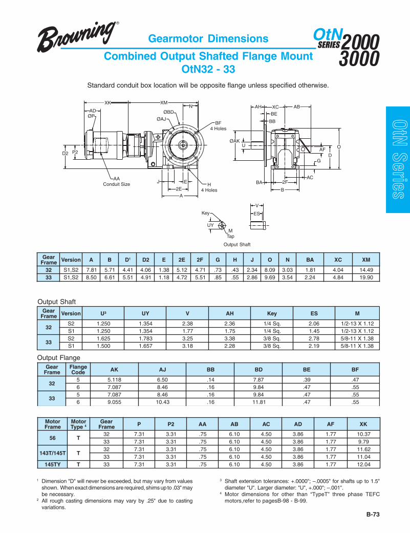
B-73
20003000
SERIESOtN
OtN Series
raeGemarF noisreV A B D1 2D E E2 F2 G H J O N AB CX MX
23 2S,1S 18.7 17.5 14.4 60.4 83.1 21.5 17.4 37. 34. 43.2 90.8 30.3 18.1 40.4 94.4133 2S,1S 05.8 16.6 15.5 19.4 81.1 27.4 15.5 58. 55. 68.2 96.9 45.3 42.2 48.4 09.91
rotoMemarF
rotoMepyT 4
raeGemarF P 2P AA BA CA DA FA KX
65 T23 13.7 13.3 57. 01.6 05.4 68.3 77.1 73.0133 13.7 13.3 57. 01.6 05.4 68.3 77.1 97.9
T541/T341 T23 13.7 13.3 57. 01.6 05.4 68.3 77.1 26.1133 13.7 13.3 57. 01.6 05.4 68.3 77.1 40.11
YT541 T 33 13.7 13.3 57. 01.6 05.4 68.3 77.1 40.21
1 Dimension "D" will never be exceeded, but may vary from valuesshown. When exact dimensions are required, shims up to .03" maybe necessary.
2 All rough casting dimensions may vary by .25" due to castingvariations.
3 Shaft extension tolerances: +.0000"; –.0005" for shafts up to 1.5"diameter "U". Larger diameter: "U", +.000"; –.001".
4 Motor dimensions for other than “TypeT” three phase TEFCmotors,refer to pagesB-98 - B-99.
Gearmotor Dimensions
Combined Output Shafted Flange MountOtN32 - 33
Standard conduit box location will be opposite flange unless specified otherwise.
raeGemarF noisreV ³U YU V HA yeK SE M
232S 052.1 453.1 83.2 63.2 .qS4/1 60.2 21.1X31-2/11S 052.1 453.1 77.1 57.1 .qS4/1 54.1 21.1X31-2/1
332S 526.1 387.1 52.3 83.3 .qS8/3 87.2 83.1X11-8/51S 005.1 756.1 81.3 82.2 .qS8/3 91.2 83.1X11-8/5
raeGemarF
egnalFedoC KA JA BB DB EB FB
235 811.5 05.6 41. 78.7 93. 74.6 780.7 64.8 61. 48.9 74. 55.
335 780.7 64.8 61. 48.9 74. 55.6 550.9 34.01 61. 18.11 74. 55.
AH
BB
O
AB
AFD
E
A
J
2E
UYM
Tap
ES
V
ØAK
Key
U
BA
B
2FAC
G
NØBD
ØAJ
XCBE
D2
XK
AD
P2
ØP
XM
BF4 Holes
AAConduit Size H
4 Holes
Output Shaft
Output Shaft
Output Flange

20003000
SERIESOtN
B-74
OtN Series
raeGemarF noisreV A B D1 2D E E2 F2 G H J O N AB CX MX
43 2S,1S 31.01 78.7 90.7 75.5 75.1 19.5 05.6 70.1 17. 76.2 50.21 94.4 39.1 81.5 55.1253 2S 29.11 66.8 53.8 65.6 71.2 90.7 90.7 91.1 78. 54.3 85.31 02.5 22.2 67.5 78.32
Gearmotor Dimensions
Combined Output Shafted Flange MountOtN34 - 35
raeGemarF noisreV ³U YU V HA yeK SE M
432S 000.2 12.2 49.3 49.3 .qS2/1 60.3 16.1X01-4/31S 057.1 909.1 65.3 82.3 .qS8/3 65.3 16.1X01-4/3
53 2S 573.2 836.2 27.4 27.4 .qS8/5 18.3 16.1X01-4/3
raeGemarF
egnalFedoC KA JA BB DB EB FB
435 550.9 34.01 61. 18.11 95. 55.6 248.9 08.11 61. 77.31 95. 17.
535 248.9 08.11 02. 77.31 17. 17.6 018.11 77.31 02. 57.51 17. 17.
rotoMemarF
rotoMepyT 4
raeGemarF P 2P AA BA CA DA FA KX
65 T ynA 13.7 13.3 57. 01.6 05.4 68.3 77.1 97.9
T541/T341 T ynA 13.7 13.3 57. 01.6 05.4 68.3 77.1 40.11
YT541 T ynA 13.7 13.3 57. 01.6 05.4 68.3 77.1 40.21
T481/T281 T 53 65.9 43.4 57. 01.6 05.4 31.5 77.1 40.41
1 Dimension "D" will never be exceeded, but may vary from valuesshown. When exact dimensions are required, shims up to .03" maybe necessary.
2 All rough casting dimensions may vary by .25" due to castingvariations.
3 Shaft extension tolerances: +.0000"; –.0005" for shafts up to 1.5"diameter "U". Larger diameter: "U", +.000"; –.001".
4 Motor dimensions for other than “TypeT” three phase TEFCmotors,refer to pages B-98 - B-99.
Output Shaft
Output Shaft
Output Flange
Standard conduit box location will be opposite flange unless specified otherwise.
AH
BB
O
AB
AFD
E
A
JAAConduit Size
2E
UYM
Tap
ES
V
ØAK
Key
U
BA
B
2FAC
G
N
BF4 Holes
H4 Holes
ØBDØAJ
XCBE
D2
XK
AD
P2
ØP
XM

B-75
20003000
SERIESOtN
OtN SeriesGearmotor Dimensions
Combined Output Shafted Flange MountOtN26 - 28
1 Dimension "D" will never be exceeded, but may vary from valuesshown. When exact dimensions are required, shims up to .03" maybe necessary.
2 All rough casting dimensions may vary by .25" due to castingvariations.
3 Shaft extension tolerances: +.0000"; –.0005" for shafts up to 1.5"diameter "U". Larger diameter: "U", +.000"; –.001".
4 Motor dimensions for other than “TypeT” three phase TEFCmotors,refer to pages B-98 - B-99.
Output Shaft
Output Shaft
Output Flange
Standard conduit box location will be opposite flange unless specified otherwise.
XM
D2 P2
AAConduit Size
XK
ØP
ADXC
B
2F
UYMTap
E
A
H4 Holes
BF8 Holes
2E
Key
J
VES
NØAJ ØBD
UAK
BA
BBBEAH
O
DG
AC
AF
AB
raeGemarF noisreV A B D1 2D E E2 F2 G H J O N AB CX
MXT481-65 T512-T312 PU-T452
A62 1S 37.61 24.11 68.8 66.7 99.6 89.31 54.9 75.1 78. 45.3 56.61 47.8 45.3 00.9 08.03 08.03 08.03A72 1S 92.91 06.21 48.9 98.7 72.8 45.61 36.01 77.1 49. 49.3 05.81 40.01 45.3 55.8 74.13 74.13 74.13A82 1S 32.32 41.61 04.21 04.01 40.01 80.02 87.31 79.1 20.1 33.4 07.32 10.21 47.3 15.11 41.73 41.73 94.73
raeGemarF noisreV ³U YU V HA yeK SE M
A62 1S 578.2 002.3 57.5 57.5 .qS4/3 31.5 79.1X01-4/3A72 1S 005.3 288.3 00.7 00.7 .qS8/7 52.6 79.1X8-1A82 1S 000.4 634.4 00.8 00.8 .qS00.1 52.7 79.1X8-1
raeGemarF
egnalFedoC JA KA BB DB EB FB
A62 5 57.51 57.31 02. 27.71 97. 17.A72 5 57.51 87.31 02. 27.71 97. 17.A82 5 96.91 27.71 42. 56.12 49. 17.
rotoMemarF
rotoMepyT 4
raeGemarF P 2P AA BA CA DA FA KX
65 T llA 13.7 13.3 57. 01.6 05.4 68.3 77.1 97.9T541/T341 T llA 13.7 13.3 57. 01.6 05.4 68.3 77.1 40.11
YT541 T llA 13.7 13.3 57. 01.6 05.4 68.3 77.1 40.21T481/T281 T llA 65.9 43.4 57. 01.6 05.4 31.5 77.1 40.41
T312 T llA 52.11 60.5 00.1 24.8 71.7 06.5 24.2 51.61T512 T llA 52.11 60.5 00.1 24.8 71.7 06.5 24.2 56.71T452 T A82,A72 83.31 00.6 52.1 97.9 86.7 92.8 18.1 16.91T652 T A82 83.31 00.6 52.1 97.9 86.7 92.8 18.1 63.12T482 T A82 83.31 00.6 05.1 85.01 81.8 92.8 31.2 68.12T682 T A82 83.31 00.6 05.1 33.01 39.7 92.8 31.2 63.32

20003000
SERIESOtN
B-76
OtN Series
1 Dimension "D" will never be exceeded, but may vary from values shown.When exact dimensions are required, shims up to .03" may be necessary.
2 All rough casting dimensions may vary by .25" due to casting variations.3 Refer to page B-24 by gear frame for Tapered Bushed designs if driven
shaft varies from "U" dimensions offered above.4 Driven shaft entry can be from either side of the gear reducer housing by
reversing positioning of the snap rings and washer illustrated.
5 Output key supplied only on frame 34 in "S2" version.6 For details of the torque arm kit, refer to page B-22.7 Output bore tolerance: +.0020", - .0000" for all diameters.8 Motor dimensions for other than "Type T" three phase TEFC motors,
refer to pages B-98 - B-99.
rotoMemarF
rotoMepyT 8
raeGemarF P 2P AA BA CA DA FA KX
65 T ynA 13.7 13.3 57. 01.6 05.4 68.3 77.1 97.9T541/T341 T ynA 13.7 13.3 57. 01.6 05.4 68.3 77.1 40.11
YT541 T ynA 13.7 13.3 57. 01.6 05.4 68.3 77.1 40.21T481/T281 T ynA 65.9 43.4 57. 01.6 05.4 31.5 77.1 40.41
T312 T 33 52.11 60.5 00.1 24.8 71.7 06.5 24.2 51.61T512 T 33 52.11 60.5 00.1 24.8 71.7 06.5 24.2 56.71
Gearmotor Dimensions
3-Stage Finished Bore Hollow ShaftOtN32 - 33
Output Shaft
Output Shaft
Standard conduit box location will be F1 unless specified otherwise.
raeGemarF noisreV A B D1 2D E E2 F2 G H J O N GW MX
23 2S 18.7 17.5 14.4 87.3 83.1 21.5 17.4 37. 34. 43.2 90.8 30.3 22.3 89.0133 2S 05.8 16.6 15.5 42.5 81.1 27.4 15.5 58. 55. 68.2 96.9 45.3 37.3 09.21
raeGemarF noisreV AE HE U 73 FU YU GV HV yeK 5 M
23 2S 89.2 59.5 573.1 69.1 325.1 02.5 55. 61/311X61/5X61/5 00.1X31-2/133 2S 74.3 49.6 005.1 61.2 476.1 69.5 55. 4/12X8/3X8/3 57.1X11-8/5
2E
A
H4 Holes
AAConduit Size
XM
AD
XK
D2 P2
J
ØP EA
AB
OAF
E2F
B
AC
G
D
N WG
UY UUF
M
VG
VH
Key EH

B-77
20003000
SERIESOtN
OtN Series
Output Shaft
1 Dimension "D" will never be exceeded, but may vary from values shown.When exact dimensions are required, shims up to .03" may be necessary.
2 All rough casting dimensions may vary by .25" due to casting variations.3 Refer to page B-24 by gear frame for Tapered Bushed designs if driven
shaft varies from "U" dimensions offered above.4 Driven shaft entry can be from either side of the gear reducer housing by
reversing positioning of the snap rings and washer illustrated.
5 Output key supplied only on frame 34 in "S2" version.6 For details of the torque arm kit, refer to page B-22.7 Output bore tolerance: +.0020", - .0000" for all diameters.8 Motor dimensions for other than "Type T" three phase TEFC motors,
refer to pagesB-98 - B-99.
Standard conduit box location will be F1 unless specified otherwise.
raeGemarF noisreV A B D1 2D E E2 F2 G H J O N GW
MXT512-T65 T682-T452
43 2S 31.01 78.7 90.7 09.5 75.1 19.5 05.6 70.1 17. 76.2 50.21 94.4 66.4 65.41 -53 2S 29.11 66.8 53.8 98.6 71.2 90.7 90.7 81.1 78. 54.3 85.31 02.5 51.5 09.61 52.71
raeGemarF noisreV AE HE U3 7 FU YU GV HV yeK 5 M
43 2S 94.4 79.8 000.2 65.2 012.2 44.7 97. 8/52X61/7X2/1 57.1X11-8/553 2S 38.4 66.9 573.2 45.3 656.2 51.8 49. 8/53X8/5X8/5 00.2X01-4/3
rotoMemarF
rotoMepyT 8
raeGemarF P 2P AA BA CA DA FA KX
65 T ynA 13.7 13.3 57. 01.6 05.4 68.3 77.1 97.9T541/T341 T ynA 13.7 13.3 57. 01.6 05.4 68.3 77.1 40.11
YT541 T ynA 13.7 13.3 57. 01.6 05.4 68.3 77.1 40.21T481/T281 T ynA 65.9 43.4 57. 01.6 05.4 31.5 77.1 40.41
T312 T ynA 52.11 60.5 00.1 24.8 71.7 06.5 24.2 51.61T512 T ynA 52.11 60.5 00.1 24.8 71.7 06.5 24.2 56.71
T452T 43 83.31 00.6 52.1 97.9 86.7 92.8 18.1 85.02T 53 83.31 00.6 52.1 97.9 86.7 92.8 18.1 16.91
T652T 43 83.31 00.6 52.1 97.9 86.7 92.8 18.1 33.22T 53 83.31 00.6 52.1 97.9 86.7 92.8 18.1 63.12
T482 T 53 83.31 00.6 05.1 85.01 81.8 92.8 31.2 68.12T682 T 53 83.31 00.6 05.1 33.01 39.7 92.8 31.2 63.32
Gearmotor Dimensions
3-Stage Finished Bore Hollow ShaftOtN34 - 35
AB
AC
XK
D2
AD
P2
AAConduit Size H
4 Holes
ØP N
XM
A
J
2EE
AF
WGEA
O
G
D
2FB
UY UUF
M
VG
VH
Key EH
Output Shaft

20003000
SERIESOtN
B-78
OtN Series
1 Dimension "D" will never be exceeded, but may vary from values shown.When exact dimensions are required, shims up to .03" may be necessary.
2 All rough casting dimensions may vary by .25" due to casting variations.3 Driven shaft entry can be from either side of the gear reducer housing by
reversing positioning of the snap rings and washer illustrated.
4 Output key supplied only on frame 34 in "S2" version.5 For details of the torque arm kit, refer to page B-23.6 Output bore tolerance: +.0020", - .0000" for all diameters.7 Motor dimensions for other than "Type T" three phase TEFC motors,
refer to pages B-98 - B-99.
Gearmotor Dimensions
3-Stage Finished Bore Hollow ShaftOtN26 - 28
Output Shaft
Standard conduit box location will be F1 unless specified otherwise.
raeGemarF noisreV A B D1 2D E E2 F2 G H J O N GW
MXT481-T281 T512-T312 PU-T452
62 1S 37.61 24.11 68.8 34.8 99.6 89.31 54.9 75.1 78. 45.3 56.61 47.8 79.6 22.32 22.42 12.2272 1S 92.91 06.21 48.9 66.8 72.8 45.61 36.01 77.1 49. 49.3 05.81 40.01 27.7 03.52 03.62 03.4282 1S 32.32 41.61 04.21 24.11 40.01 80.02 87.31 79.1 20.1 33.4 07.32 10.21 94.9 - 40.33 59.82
raeGemarF noisreV AE HE U6 FU YU GV HV yeK 4 M
62 1S 01.6 02.21 057.2 53.3 720.3 52.01 19. .qS8/5 01-4/372 1S 07.6 04.31 521.3 57.3 454.3 04.11 19. .qS4/3 01-4/382 1S 54.8 09.61 526.3 53.4 900.4 59.41 20.1 .qS8/7 8-1
rotoMemarF
rotoMepyT 7
raeGemarF P 2P AA BA CA DA FA KX
T481/T281 T 72,62 65.9 43.4 57. 01.6 05.4 31.5 77.1 30.21T312 T llA 52.11 60.5 00.1 24.8 71.7 06.5 24.2 57.31T512 T llA 52.11 60.5 00.1 24.8 71.7 06.5 24.2 52.51T452 T llA 83.31 00.6 52.1 97.9 86.7 92.8 18.1 16.91T652 T llA 83.31 00.6 52.1 97.9 86.7 92.8 18.1 63.12T482 T llA 83.31 00.6 05.1 85.01 81.8 92.8 31.2 68.12T682 T llA 83.31 00.6 05.1 33.01 39.7 92.8 31.2 63.32
T623/T423 T 82,72 02.71 87.7 00.2 99.41 43.11 61.41 36.3 69.42T563/T463 T 82,72 22.81 11.9 00.3 13.61 91.21 73.41 83.3 31.62
Output Shaft
XK
D2
AD
P2
ØP
AB
WGN
XM
EA
O
EH
VG
UF U
E
A
H4 Holes
AAConduit Size
2E
J
UY
M
VH
Key
AC
B
2F
AF
G
D

B-79
20003000
SERIESOtN
OtN Series
Standard conduit box location will be F1 unless specified otherwise.
Gearmotor Dimensions
Combined Finished Bore Hollow ShaftOtN32 - 33
Output Shaft
raeGemarF noisreV A B D1 2D E E2 F2 G H J O N GW MX
23 2S 18.7 17.5 14.4 60.4 83.1 21.5 17.4 37. 34. 43.2 90.8 30.3 22.3 94.4133 2S 05.8 16.6 15.5 19.4 81.1 27.4 15.5 58. 55. 68.2 96.9 45.3 37.3 09.91
raeGemarF noisreV AE HE U3 6 FU YU GV HV yeK M
23 2S 89.2 69.5 573.1 69.1 325.1 02.5 55. 61/311X61/5X61/5 00.1X31-2/133 2S 74.3 49.6 005.1 61.2 476.1 69.5 55. 4/12X8/3X8/3 57.1X11-8/5
rotoMemarF
rotoMepyT 7
raeGemarF P 2P AA BA CA DA FA KX
65T 23 13.7 13.3 57. 01.6 05.4 68.3 77.1 73.01T 33 13.7 13.3 57. 01.6 05.4 68.3 77.1 97.9
T541/T341T 23 13.7 13.3 57. 01.6 05.4 68.3 77.1 26.11T 33 13.7 13.3 57. 01.6 05.4 68.3 77.1 40.11
YT541 T 33 13.7 13.3 57. 01.6 05.4 68.3 77.1 40.21
Output Shaft
2E
A
J
EA
AB
OAF
E 2F
B
AC
G
D
N WG
D2
AAConduit Size H
4 Holes
XKAD
P2
ØP
XM
UY UUF
M
VG
VH
Key EH
1 Dimension "D" will never be exceeded, but may vary from values shown.When exact dimensions are required, shims up to .03" may be necessary.
2 All rough casting dimensions may vary by .25" due to casting variations.3 Refer to page B-24 by gear frame for Tapered Bushed designs if driven
shaft varies from "U" dimensions offered above.
4 Driven shaft entry can be from either side of the gear reducer housing byreversing positioning of the snap rings and washer illustrated.
5 For details of the torque arm kit, refer to page B-22.6 Output bore tolerance: +.0020", - .0000" for all diameters.7 Motor dimensions for other than "Type T" three phase TEFC motors,
refer to pages B-98 - B-99.

20003000
SERIESOtN
B-80
OtN Series
Gearmotor Dimensions
Combined Finished Bore Hollow ShaftOtN34 - 35
Output Shaft
Standard conduit box location will be F1 unless specified otherwise.
raeGemarF noisreV A B D1 2D E E2 F2 G H J O N GW MX
43 2S 31.01 78.7 90.7 75.5 75.1 19.5 05.6 70.1 17. 76.2 50.21 94.4 66.4 55.1253 2S 29.11 66.8 53.8 65.6 71.2 90.7 90.7 81.1 78. 54.3 85.31 02.5 51.5 78.32
raeGemarF noisreV AE HE U3 7 FU YU GV HV yeK 5 M
43 2S 94.4 79.8 000.2 65.2 012.2 44.7 97. 8/52X61/7X2/1 57.1X11-8/553 2S 38.4 66.9 573.2 45.3 656.2 51.8 49. 8/53X8/5X8/5 00.2X01-4/3
rotoMemarF
rotoMepyT 8
raeGemarF P 2P AA BA CA DA FA KX
65 T ynA 13.7 13.3 57. 01.6 05.4 68.3 77.1 97.9T541/T341 T ynA 13.7 13.3 57. 01.6 05.4 68.3 77.1 40.11
YT541 T ynA 13.7 13.3 57. 01.6 05.4 68.3 77.1 40.21T481/T281 T 53 65.9 43.4 57. 01.6 05.4 31.5 77.1 40.41
1 Dimension "D" will never be exceeded, but may vary from values shown.When exact dimensions are required, shims up to .03" may be necessary.
2 All rough casting dimensions may vary by .25" due to casting variations.3 Refer to page B-24 by gear frame for Tapered Bushed designs if driven
shaft varies from "U" dimensions offered above.4 Driven shaft entry can be from either side of the gear reducer housing by
reversing positioning of the snap rings and washer illustrated.
5 Output key supplied only on frame 34 in "S2" version.6 For details of the torque arm kit, refer to page B-22.7 Output bore tolerance: +.0020", - .0000" for all diameters.8 Motor dimensions for other than "Type T" three phase TEFC motors,
refer to pages B-98 - B-99.
Output Shaft
2E
A
JAA
Conduit Size
EA
AB
OAF
E H4 Holes
2F
B
AC
G
D
N WG
D2
XKAD
P2
ØP
XM
UY UUF
M
VG
VH
Key EH

B-81
20003000
SERIESOtN
OtN Series
raeGemarF noisreV A B D1 2D E E2 F2 G H J O N GW
MXT481-65 T512-T312 PU-T452
A62 1S 37.61 24.11 68.8 66.7 99.6 89.31 54.9 75.1 78. 45.3 56.61 47.8 79.6 08.03 08.03 08.03A72 1S 92.91 06.21 48.9 98.7 72.8 45.61 36.01 77.1 49. 49.3 05.81 40.01 27.7 74.13 74.13 74.13A82 1S 32.32 41.61 04.21 04.01 40.01 80.02 87.31 79.1 20.1 33.4 07.32 10.21 94.9 41.73 41.73 94.73
Standard conduit box location will be F1 unless specified otherwise.
Gearmotor Dimensions
Combined Finished Bore Hollow ShaftOtN26 - 28
Output Shaft
1 Dimension "D" will never be exceeded, but may vary from values shown.When exact dimensions are required, shims up to .03" may be necessary.
2 All rough casting dimensions may vary by .25" due to casting variations.3 Driven shaft entry can be from either side of the gear reducer housing by
reversing positioning of the snap rings and washer illustrated.
4 For details of the torque arm kit, refer to page B-23.5 Output bore tolerance: +.0020", - .0000" for all diameters.6 Motor dimensions for other than "Type T" three phase TEFC motors,
refer to pages B-98 - B-99.
raeGemarF noisreV AE HE U5 FU YU GV HV yeK M
A62 1S 01.6 02.21 057.2 53.3 720.3 52.01 19. .qS8/5 01-4/3A72 1S 07.6 04.31 521.3 57.3 454.3 04.11 19. .qS4/3 01-4/3A82 1S 54.8 09.61 526.3 53.4 900.4 59.41 20.1 .qS8/7 8-1
rotoMemarF
rotoMepyT 6
raeGemarF P 2P AA BA CA DA FA KX
65 T llA 13.7 13.3 57. 01.6 05.4 68.3 77.1 97.9T541/T341 T llA 13.7 13.3 57. 01.6 05.4 68.3 77.1 40.11
YT541 T llA 13.7 13.3 57. 01.6 05.4 68.3 77.1 40.21T481/T281 T llA 65.9 43.4 57. 01.6 05.4 31.5 77.1 40.41
T312 T llA 52.11 60.5 00.1 24.8 71.7 06.5 24.2 51.61T512 T llA 52.11 60.5 00.1 24.8 71.7 06.5 24.2 56.71T452 T A82,A72 83.31 00.6 52.1 97.9 86.7 92.8 18.1 16.91T652 T A82 83.31 00.6 52.1 97.9 86.7 92.8 18.1 63.12T482 T A82 83.31 00.6 05.1 85.01 81.8 92.8 31.2 68.12T682 T A82 83.31 00.6 05.1 33.01 39.7 92.8 31.2 63.32
Output Shaft
XM
N
EH
VG
D2
AAConduit Size H
4 Holes
P2
XK
ØP
AD
J
A
2E
UF U
E
VH
G
D
O
AC
M
AF
B
UY
Key
2F
ABEA WG

20003000
SERIESOtN
B-82
OtN Series
EA
O
ABWG
AD
XK
D2
AAConduit Size
H4 Holes
P2
2EA
J E
B2F
AF
GD
AC
XM
ØPN
UY UUF
M
VG
VH
Key EH
BB
AH
AK
MF Tap
23°
48°
65°
Gear Frame - Size 32
107°
44°23° ØAJ 44°
23°
Gear Frame - Size 33
45°
68°
45°
ØAJ 23°
Gearmotor Dimensions
3-Stage Finished Bore Hollow ShaftFace Mount - OtN32 - 33
1 Dimension "D" will never be exceeded, but may vary from values shown.When exact dimensions are required, shims up to .03" may be necessary.
2 All rough casting dimensions may vary by .25" due to casting variations.3 Motor dimensions for other than "Type T" three phase TEFC motors,
refer to pages B-98 - B-99.
4 Driven shaft entry can be from either side of the gear reducer housing byreversing positioning of the snap rings and washer illustrated.
5 Output bore tolerance: +.0020", - .0000" for all diameters.
Output Shaft
Standard conduit box location will be opposite face mounting unless specified otherwise.
raeGemarF noisreV A B D1 2D E E2 F2 G H J O N GW MX
23 2S 18.7 17.5 14.4 87.3 83.1 21.5 17.4 37. 34. 43.2 90.8 30.3 51.3 89.0133 2S 05.8 16.6 15.5 42.5 81.1 27.4 15.5 58. 55. 68.2 96.9 45.3 36.3 09.21
raeGemarF noisreV AE HE U5 FU YU GV HV yeK M
23 2S 89.2 59.5 573.1 69.1 325.1 02.5 55. 61/311X61/5X61/5 00.1X31-2/133 2S 74.3 49.6 005.1 61.2 476.1 69.5 55. 4/12X8/3X8/3 57.1X11-8/5
Face MountraeGemarF
egnalFedoC HA JA KA BB FM
23 2S 21. 49.3 51.3 61. 78.X01M33 2S 21. 48.4 49.3 61. 78.X21M
rotoMemarF
rotoMepyT 3
raeGemarF P 2P AA BA CA DA FA KX
65 T ynA 13.7 13.3 57. 01.6 05.4 68.3 77.1 97.9T541/T341 T ynA 13.7 13.3 57. 01.6 05.4 68.3 77.1 40.11
YT541 T ynA 13.7 13.3 57. 01.6 05.4 68.3 77.1 40.21T481/T281 T ynA 65.9 43.4 57. 01.6 05.4 31.5 77.1 40.41
T312 T 33 52.11 60.5 00.1 24.8 71.7 06.5 24.2 51.61T512 T 33 52.11 60.5 00.1 24.8 71.7 06.5 24.2 56.71
Output Shaft

B-83
20003000
SERIESOtN
OtN Series
D
AB
O
G
ACJ
A2E
XMAD
XK
D2
AAConduit Size H
4 Holes
P2
ØP NWGEA
E
B2F
AF
UY UUF
M
VG
VH
Key EH
25°25°
46°
25°25°
55°
Gear Frame - Size 34
40°ØAJ
Gear Frame - Size 35
52°
59°30°
ØAJ
44°
BBAH
AK
MF Tap44° 44°44°
Output Shaft
Gearmotor Dimensions
3-Stage Finished Bore Hollow ShaftFace Mount - OtN34 - 35
Standard conduit box location will be opposite face mounting unless specified otherwise.
raeGemarF noisreV A B D1 2D E E2 F2 G H J O N GW
MXT512-T65 T682-T452
43 2S 31.01 78.7 90.7 09.5 75.1 19.5 05.6 70.1 17. 76.2 50.21 94.4 66.4 65.41 -53 2S 29.11 66.8 53.8 98.6 71.2 90.7 90.7 81.1 78. 54.3 85.31 02.5 51.5 09.61 52.71
raeGemarF noisreV AE HE U6 FU YU GV HV yeK 5 M
43 2S 94.4 79.8 000.2 65.2 012.2 44.7 97. 8/52X61/7X2/1 57.1X11-8/553 2S 38.4 66.9 573.2 45.3 656.2 51.8 49. 8/53X8/5X8/5 00.2X01-4/3
raeGemarF noisreV HA JA KA BB FM
43 2S 41. 89.5 21.5 82. 78.X01M53 2S 31. 84.7 01.6 82. 78.X21M
rotoMemarF
rotoMepyT 3
raeGemarF P 2P AA BA CA DA FA KX
65 T ynA 13.7 13.3 57. 01.6 05.4 68.3 77.1 97.9T541/T341 T ynA 13.7 13.3 57. 01.6 05.4 68.3 77.1 40.11
YT541 T ynA 13.7 13.3 57. 01.6 05.4 68.3 77.1 40.21T481/T281 T ynA 65.9 43.4 57. 01.6 05.4 31.5 77.1 40.41
T312 T ynA 52.11 60.5 00.1 24.8 71.7 06.5 24.2 51.61T512 T ynA 52.11 60.5 00.1 24.8 71.7 06.5 24.2 56.71
T452T 43 83.31 00.6 52.1 97.9 86.7 92.8 18.1 85.02T 53 83.31 00.6 52.1 97.9 86.7 92.8 18.1 16.91
T652T 43 83.31 00.6 52.1 97.9 86.7 92.8 18.1 33.22T 53 83.31 00.6 52.1 97.9 86.7 92.8 18.1 63.12
T482 T 53 83.31 00.6 05.1 85.01 81.8 92.8 31.2 68.12T682 T 53 83.31 00.6 05.1 33.01 39.7 92.8 31.2 63.32
Output Shaft
1 Dimension "D" will never be exceeded, but may vary from values shown.When exact dimensions are required, shims up to .03" may be necessary.
2 All rough casting dimensions may vary by .25" due to casting variations.3 Motor dimensions for other than "Type T" three phase TEFC motors,
refer to pages B-98 - B-99.
4 Driven shaft entry can be from either side of the gear reducer housing byreversing positioning of the snap rings and washer illustrated.
5 Output key supplied only on frame 34 "S2" version.6 Output bore tolerance: +.0020", - .0000" for all diameters.
Face Mount

20003000
SERIESOtN
B-84
OtN Series
Gearmotor Dimensions
3-Stage Finished Bore Hollow ShaftFace Mount - OtN26 - 28
Output Shaft
Standard conduit box location will be opposite face mounting unless specified otherwise.
Face Mount
raeGemarF noisreV A B D1 2D E E2 F2 G H J O N GW
MXT481-T281 T512-T312 PU-T452
62 1S 37.61 24.11 68.8 34.8 99.6 89.31 54.9 75.1 78. 45.3 56.61 47.8 79.6 22.32 22.42 12.2272 1S 92.91 06.21 48.9 66.8 72.8 45.61 36.01 77.1 49. 49.3 05.81 40.01 27.7 03.52 03.62 03.4282 1S 32.32 41.61 04.21 24.11 40.01 80.02 87.31 79.1 20.1 33.4 07.32 10.21 94.9 - 40.33 59.82
raeGemarF noisreV AE HE U5 FU YU GV HV yeK M
62 1S 01.6 02.21 057.2 53.3 720.3 52.01 19. .qS8/5 01-4/372 1S 07.6 04.31 521.3 57.3 454.3 04.11 19. .qS4/3 01-4/382 1S 54.8 09.61 526.3 53.4 900.4 59.41 20.1 .qS8/7 8-1
raeGemarF noisreV JA KA BB DB FB
62 1S 18.11 48.9 02. 87.31 22X61M72 1S 87.31 18.11 02. 57.51 22X61M82 1S 57.51 87.31 02. 27.71 22X61M
rotoMemarF
rotoMepyT 3
raeGemarF P 2P AA BA CA DA FA KX
T481/T281 T 72,62 65.9 43.4 57. 01.6 05.4 31.5 77.1 30.21T312 T llA 52.11 60.5 00.1 24.8 71.7 06.5 24.2 57.31T512 T llA 52.11 60.5 00.1 24.8 71.7 06.5 24.2 52.51T452 T llA 83.31 00.6 52.1 97.9 86.7 92.8 18.1 16.91T652 T llA 83.31 00.6 52.1 97.9 86.7 92.8 18.1 63.12T482 T llA 83.31 00.6 05.1 85.01 81.8 92.8 31.2 68.12T682 T llA 83.31 00.6 05.1 33.01 39.7 92.8 31.2 63.32
T623/T423 T 82,72 02.71 87.7 00.2 99.41 43.11 61.41 36.3 69.42T563/T463 T 82,72 22.81 11.9 00.3 13.61 91.21 73.41 83.3 31.62
1 Dimension "D" will never be exceeded, but may vary from values shown.When exact dimensions are required, shims up to .03" may be necessary.
2 All rough casting dimensions may vary by .25" due to casting variations.3 Motor dimensions for other than "Type T" three phase TEFC motors,
refer to pages B-98 - B-99.
4 Driven shaft entry can be from either side of the gear reducer housing byreversing positioning of the snap rings and washer illustrated.
5 Output bore tolerance: +.0020", - .0000" for all diameters.
D2 P2
AAConduit Size
XK
AD
XM
N
BF8 Holes
WG
EA AB
BB
2F
B
UUF
H4 Holes
2E
E
A
ØP
J
VG
EH
VH
M
UY
Key
ØAK
D
AFO
G
AC
ØAJ ØBD
Output Shaft

B-85
20003000
SERIESOtN
OtN Series
Output Shaft
Gearmotor Dimensions
Combined Finished Bore Hollow ShaftFace Mount - OtN32 - 33
Standard conduit box location will be opposite face mounting unless specified otherwise.
raeGemarF noisreV A B D1 2D E E2 F2 G H J O N GW MX
23 2S 18.7 17.5 14.4 60.4 83.1 21.5 17.4 37. 34. 43.2 90.8 30.3 51.3 94.4133 2S 05.8 16.6 15.5 19.4 81.1 27.4 15.5 58. 55. 68.2 96.9 45.3 36.3 09.91
raeGemarF noisreV AE HE U5 FU YU GV HV yeK M
23 2S 89.2 69.5 573.1 69.1 325.1 02.5 55. 61/311X61/5X61/5 00.1X31-2/133 2S 74.3 49.6 005.1 61.2 476.1 69.5 55. 4/12X8/3X8/3 57.1X11-8/5
rotoMemarF
rotoMepyT 3
raeGemarF P 2P AA BA CA DA FA KX
65T 23 13.7 13.3 57. 01.6 05.4 68.3 77.1 73.01T 33 13.7 13.3 57. 01.6 05.4 68.3 77.1 97.9
T541/T341T 23 13.7 13.3 57. 01.6 05.4 68.3 77.1 26.11T 33 13.7 13.3 57. 01.6 05.4 68.3 77.1 40.11
YT541 T 33 13.7 13.3 57. 01.6 05.4 68.3 77.1 40.21
1 Dimension "D" will never be exceeded, but may vary from values shown.When exact dimensions are required, shims up to .03" may be necessary.
2 All rough casting dimensions may vary by .25" due to casting variations.3 Motor dimensions for other than "Type T" three phase TEFC motors,
refer to pages B-98 - B-99.
4 Driven shaft entry can be from either side of the gear reducer housing byreversing positioning of the snap rings and washer illustrated.
5 Output bore tolerance: +.0020", - .0000" for all diameters.
Output Shaft
UY UUF
M
VG
VH
Key EH
EA
O
ABWG
2EA
J E
B2F
AF
GD
AC
N
D2
AAConduit Size H
4 Holes
XK
AD
P2
ØP
XM
BB
AH
AK
MF Tap
23°
48°
65°
Gear Frame - Size 32
107°
44°23° ØAJ 44°
23°
Gear Frame - Size 33
45°
68°
45°
ØAJ 23°
raeGemarF noisreV HA JA KA BB FM
23 2S 21. 49.3 51.3 61. 78.X01M33 2S 21. 48.4 49.3 61. 78.X21M
Face Mount

20003000
SERIESOtN
B-86
OtN Series
Gearmotor Dimensions
Combined Finished Bore Hollow ShaftFace Mount - OtN34 - 35
Output Shaft
Standard conduit box location will be opposite face mounting unless specified otherwise.
1 Dimension "D" will never be exceeded, but may vary from values shown.When exact dimensions are required, shims up to .03" may be necessary.
2 All rough casting dimensions may vary by .25" due to casting variations.3 Motor dimensions for other than "Type T" three phase TEFC motors,
refer to pages B-98 - B-99.
4 Driven shaft entry can be from either side of the gear reducer housing byreversing positioning of the snap rings and washer illustrated.
5 Output key supplied only on frame 34 "S2" version.6 Output bore tolerance: +.0020", - .0000" for all diameters.
Output Shaft
raeGemarF noisreV A B D1 2D E E2 F2 G H J O N GW MX
43 2S 31.01 78.7 90.7 75.5 75.1 19.5 05.6 70.1 17. 76.2 50.21 94.4 66.4 55.1253 2S 29.11 66.8 53.8 65.6 71.2 90.7 90.7 81.1 78. 54.3 85.31 02.5 51.5 78.32
raeGemarF noisreV AE HE U6 FU YU GV HV yeK 5 M
43 2S 94.4 79.8 000.2 65.2 012.2 44.7 97. 8/52X61/7X2/1 57.1X11-8/553 2S 38.4 66.9 573.2 45.3 656.2 51.8 49. 8/53X8/5X8/5 00.2X01-4/3
rotoMemarF
rotoMepyT 3
raeGemarF P 2P AA BA CA DA FA KX
65 T ynA 13.7 13.3 57. 01.6 05.4 68.3 77.1 97.9T541/T341 T ynA 13.7 13.3 57. 01.6 05.4 68.3 77.1 40.11
YT541 T ynA 13.7 13.3 57. 01.6 05.4 68.3 77.1 40.21T481/T281 T 53 65.9 43.4 57. 01.6 05.4 31.5 77.1 40.41
EA
O
AB
WG
2EA
J E
B2F
AF
GD
AC
N
D2
AAConduit Size H
4 Holes
XK
AD
P2
ØP
XM
UY UUF
M
VG
VH
Key EH
25°25°
46°
25°25° BB
AH
55°
Gear Frame - Size 34
AK
40°ØAJ
Gear Frame - Size 35
52°
59°30°
ØAJ
44°MF Tap
44° 44°44°
raeGemarF noisreV HA JA KA BB FM
43 2S 41. 89.5 21.5 82. 78.X01M53 2S 31. 84.7 01.6 82. 78.X21M
Face Mount

B-87
20003000
SERIESOtN
OtN Series
Output Shaft
Gearmotor Dimensions
Combined Finished Bore Hollow ShaftFace Mount - OtN26 - 28
Standard conduit box location will be opposite face mounting unless specified otherwise.
1 Dimension "D" will never be exceeded, but may vary from values shown.When exact dimensions are required, shims up to .03" may be necessary.
2 All rough casting dimensions may vary by .25" due to casting variations.3 Motor dimensions for other than "Type T" three phase TEFC motors,
refer to pages B-98 - B-99.
4 Driven shaft entry can be from either side of the gear reducer housing byreversing positioning of the snap rings and washer illustrated.
5 Output bore tolerance: +.0020", - .0000" for all diameters.
Output Shaft
raeGemarF noisreV A B D1 2D E E2 F2 G H J O N GW
MXT481-65 T512-T312 PU-T452
A62 1S 37.61 24.11 68.8 66.7 99.6 89.31 54.9 75.1 78. 45.3 56.61 47.8 79.6 08.03 08.03 08.03A72 1S 92.91 06.21 48.9 98.7 72.8 45.61 36.01 77.1 49. 49.3 05.81 40.01 27.7 74.13 74.13 74.13A82 1S 32.32 41.61 04.21 04.01 40.01 80.02 87.31 79.1 20.1 33.4 07.32 10.21 94.9 41.73 41.73 94.73
raeGemarF noisreV AE HE U5 FU YU GV HV yeK M
A62 1S 01.6 02.21 057.2 53.3 720.3 52.01 19. .qS8/5 01-4/3A72 1S 07.6 04.31 521.3 57.3 454.3 04.11 19. .qS4/3 01-4/3A82 1S 54.8 09.61 526.3 53.4 900.4 59.41 20.1 .qS8/7 8-1
raeGemarF noisreV JA KA BB DB FB
A62 1S 18.11 48.9 02. 87.31 22X61MA72 1S 87.31 18.11 02. 57.51 22X61MA82 1S 57.51 87.31 02. 27.71 22X61M
rotoMemarF
rotoMepyT 3
raeGemarF P 2P AA BA CA DA FA KX
65 T llA 13.7 13.3 57. 01.6 05.4 68.3 77.1 97.9T541/T341 T llA 13.7 13.3 57. 01.6 05.4 68.3 77.1 40.11
YT541 T llA 13.7 13.3 57. 01.6 05.4 68.3 77.1 40.21T481/T281 T llA 65.9 43.4 57. 01.6 05.4 31.5 77.1 40.41
T312 T llA 52.11 60.5 00.1 24.8 71.7 06.5 24.2 51.61T512 T llA 52.11 60.5 00.1 24.8 71.7 06.5 24.2 56.71T452 T A82,A72 83.31 00.6 52.1 97.9 86.7 92.8 18.1 16.91T652 T A82 83.31 00.6 52.1 97.9 86.7 92.8 18.1 63.12T482 T A82 83.31 00.6 05.1 85.01 81.8 92.8 31.2 68.12T682 T A82 83.31 00.6 05.1 33.01 39.7 92.8 31.2 63.32
Face Mount
XM
E
EH
VG
2E
A
N
D2
XK
P2
AAConduit Size H
4 Holes
BF8 Holes
AD
ØP
J
UUF
ØAJØBD
AC
2F
B
AB
WG
OØAK
UY
VH
M Key
EA
BB
DG
AF

20003000
SERIESOtN
B-88
OtN Series
Gearmotor Dimensions
3-Stage Finished Bore Hollow ShaftFlange Mount - OtN32 - 33
Output Shaft
Standard conduit box location will be opposite flange unless specified otherwise.
1 Dimension "D" will never be exceeded, but may vary from values shown.When exact dimensions are required, shims up to .03" may be necessary.
2 All rough casting dimensions may vary by .25" due to casting variations.3 Motor dimensions for other than "Type T" three phase TEFC motors,
refer to pages B-98 - B-99.
4 Driven shaft entry can be from either side of the gear reducer housing byreversing positioning of the snap rings and washer illustrated.
5 Output bore tolerance: +.0020", - .0000" for all diameters.
Output Shaft
raeGemarF noisreV A B D1 2D E E2 F2 G H J O N AB GW CX MX
23 2S 18.7 17.5 14.4 87.3 83.1 21.5 17.4 37. 34. 43.2 90.8 30.3 18.1 22.3 40.4 89.0133 2S 05.8 16.6 15.5 42.5 81.1 27.4 15.5 58. 55. 68.2 96.9 45.3 80.2 37.3 48.4 09.21
raeGemarF noisreV AE HE U5 FU YU GV HV yeK M
23 2S 89.2 69.5 573.1 69.1 325.1 02.5 55. 61/311X61/5X61/5 00.1X31-2/133 2S 74.3 49.6 005.1 61.2 476.1 69.5 55. 4/12X8/3X8/3 57.1X11-8/5
raeGemarF
egnalFedoC KA JA BB DB EB FB
235 811.5 05.6 41. 78.7 93. 74.6 780.7 64.8 61. 48.9 74. 55.
335 780.7 64.8 61. 48.9 74. 55.6 550.9 34.01 61. 18.11 74. 55.
rotoMemarF
rotoMepyT 3
raeGemarF P 2P AA BA CA DA FA KX
65 T ynA 13.7 13.3 57. 01.6 05.4 68.3 77.1 97.9T541/T341 T ynA 13.7 13.3 57. 01.6 05.4 68.3 77.1 40.11
YT541 T ynA 13.7 13.3 57. 01.6 05.4 68.3 77.1 40.21T481/T281 T ynA 65.9 43.4 57. 01.6 05.4 31.5 77.1 40.41
T312 T 33 52.11 60.5 00.1 24.8 71.7 06.5 24.2 51.61T512 T 33 52.11 60.5 00.1 24.8 71.7 06.5 24.2 56.71
Output Flange
A
2E
XMXK
AD
D2 P2
J
AAConduit Size
H4 Holes
BF4 Holes
ØPØBD
ØAJ
EA AB
WG
BB
OD
AF
G
ØAK
E
B
2F
AC
BA
NXC
BE
UY UUF
M
VG
VH
Key EH

B-89
20003000
SERIESOtN
OtN Series
rotoMemarF
rotoMepyT 3
raeGemarF P 2P AA BA CA DA FA KX
65 T ynA 13.7 13.3 57. 01.6 05.4 68.3 77.1 97.9T541/T341 T ynA 13.7 13.3 57. 01.6 05.4 68.3 77.1 40.11
YT541 T ynA 13.7 13.3 57. 01.6 05.4 68.3 77.1 40.21T481/T281 T ynA 65.9 43.4 57. 01.6 05.4 31.5 77.1 40.41
T312 T ynA 52.11 60.5 00.1 24.8 71.7 06.5 24.2 51.61T512 T ynA 52.11 60.5 00.1 24.8 71.7 06.5 24.2 56.71
T452T 43 83.31 00.6 52.1 97.9 86.7 92.8 18.1 85.02T 53 83.31 00.6 52.1 97.9 86.7 92.8 18.1 16.91
T652T 43 83.31 00.6 52.1 97.9 86.7 92.8 18.1 33.22T 53 83.31 00.6 52.1 97.9 86.7 92.8 18.1 63.12
T482 T 53 83.31 00.6 05.1 85.01 81.8 92.8 31.2 68.12T682 T 53 83.31 00.6 05.1 33.01 39.7 92.8 31.2 63.32
Output Shaft
Standard conduit box location will be opposite flange unless specified otherwise.
Output Shaft
Output Flange
Gearmotor Dimensions
3-Stage Finished Bore Hollow ShaftFlange Mount - OtN34 - 35
raeGemarF noisreV A B D1 2D E E2 F2 G H J O N AB GW CX
MXT512-T65 T682-T452
43 2S 31.01 78.7 90.7 09.5 75.1 19.5 05.6 70.1 17. 76.2 50.21 94.4 39.1 66.4 81.5 65.41 -53 2S 29.11 66.8 53.8 98.6 71.2 90.7 90.7 81.1 78. 54.3 85.31 02.5 22.2 51.5 67.5 09.61 52.71
raeGemarF noisreV AE HE U6 FU YU GV HV yeK 5 M
43 2S 94.4 79.8 000.2 65.2 012.2 44.7 97. 8/52X61/7X2/1 57.1X11-8/553 2S 38.4 66.9 573.2 45.3 656.2 51.8 49. 8/53X8/5X8/5 00.2X01-4/3
raeGemarF
egnalFedoC KA JA BB DB EB FB
435 550.9 34.01 61. 08.11 95. 55.6 248.9 08.11 61. 77.31 95. 17.
535 248.9 08.11 02. 77.31 17. 17.6 018.11 77.31 02. 57.51 17. 17.
1 Dimension "D" will never be exceeded, but may vary from values shown.When exact dimensions are required, shims up to .03" may be necessary.
2 All rough casting dimensions may vary by .25" due to casting variations.3 Motor dimensions for other than "Type T" three phase TEFC motors,
refer to pages B-98 - B-99.
4 Driven shaft entry can be from either side of the gear reducer housing byreversing positioning of the snap rings and washer illustrated.
5 Output key supplied only on frame 34 "S2" version.6 Output bore tolerance: +.0020", - .0000" for all diameters.
XM
D2
XK
AD
P2
ØP
XC
B
2F
ØAK
2E
A
JAAConduit Size E
BA
ØAJØBD N
BF4 Holes
H4 Holes
BE
BBWG
AB
O
D
G
AC
AF
EA
UY UUF
M
VG
VH
Key EH

20003000
SERIESOtN
B-90
OtN SeriesrotoMemarF
rotoMepyT 3
raeGemarF P 2P AA BA CA DA FA KX
T481/T281 T 72,62 65.9 43.4 57. 01.6 05.4 31.5 77.1 30.21T312 T llA 52.11 60.5 00.1 24.8 71.7 06.5 24.2 57.31T512 T llA 52.11 60.5 00.1 24.8 71.7 06.5 24.2 52.51T452 T llA 83.31 00.6 52.1 97.9 86.7 92.8 18.1 16.91T652 T llA 83.31 00.6 52.1 97.9 86.7 92.8 18.1 63.12T482 T llA 83.31 00.6 05.1 85.01 81.8 92.8 31.2 68.12T682 T llA 83.31 00.6 05.1 33.01 39.7 92.8 31.2 63.32
T623/T423 T 82,72 02.71 87.7 00.2 99.41 43.11 61.41 36.3 69.42T563/T463 T 82,72 22.81 11.9 00.3 13.61 91.21 73.41 83.3 31.62
Gearmotor Dimensions
3-Stage Finished Bore Hollow ShaftFlange Mount - OtN26 - 28
Standard conduit box location will be opposite flange unless specified otherwise.
1 Dimension "D" will never be exceeded, but may vary from values shown.When exact dimensions are required, shims up to .03" may be necessary.
2 All rough casting dimensions may vary by .25" due to casting variations.3 Motor dimensions for other than "Type T" three phase TEFC motors,
refer to pages B-98 - B-99.
4 Driven shaft entry can be from either side of the gear reducer housing byreversing positioning of the snap rings and washer illustrated.
5 Output bore tolerance: +.0020", - .0000" for all diameters.
Output Shaft
raeGemarF noisreV A B D1 2D E E2 F2 G H J O N AB CX GW
MXT481-T281 T512-T312 pU-T452
62 1S 37.61 24.11 68.8 34.8 99.6 89.31 54.9 75.1 78. 45.3 56.61 47.8 45.3 00.9 79.6 22.32 22.42 12.2272 1S 92.91 06.21 48.9 66.8 72.8 45.61 36.01 77.1 49. 49.3 05.81 40.01 45.3 55.8 27.7 03.52 03.62 03.4282 1S 32.32 41.61 04.21 24.11 40.01 80.02 87.31 79.1 20.1 33.4 07.32 10.21 47.3 15.11 94.9 - 40.33 59.82
raeGemarF noisreV AE HE U5 FU YU GV HV yeK M
62 1S 01.6 02.21 057.2 53.3 720.3 52.01 19. .qS8/5 01-4/372 1S 07.6 04.31 521.3 57.3 454.3 04.11 19. .qS4/3 01-4/382 1S 54.8 09.61 526.3 53.4 900.4 59.41 20.1 .qS8/7 8-1
raeGemarF
egnalFedoC JA KA BB DB EB FB
62 5 57.51 57.31 02. 27.71 97. 17.72 5 57.51 87.31 02. 27.71 97. 17.82 5 96.91 27.71 42. 56.12 49. 17.
AAConduit Size
UUF
A
2E
XM
P2D2
J
XK
ØPAD
ØBDØAJ EA
AK
O
AB
B
BA
VHVG
KeyEHM
E H4 Holes
BF8 Holes
UY
AFD
2F
AC
G
XC
NBB
BEWG
Output Shaft
Output Flange

B-91
20003000
SERIESOtN
OtN Series
Output Shaft
Standard conduit box location will be opposite flange unless specified otherwise.
Output Shaft
Output Flange
Gearmotor Dimensions
Combined Finished Bore Hollow ShaftFlange Mount - OtN32 - 33
raeGemarF noisreV A B D1 2D E E2 F2 G H J O N AB GW CX MX
23 2S 18.7 17.5 14.4 60.4 83.1 21.5 17.4 37. 34. 43.2 90.8 30.3 18.1 22.3 40.4 94.4133 2S 05.8 16.6 15.5 19.4 81.1 27.4 15.5 58. 55. 68.2 96.9 45.3 80.2 37.3 48.4 09.91
raeGemarF noisreV AE HE U5 FU YU GV HV yeK M
23 2S 89.2 69.5 573.1 69.1 325.1 02.5 55. 61/311X61/5X61/5 00.1X31-2/133 2S 74.3 49.6 005.1 61.2 476.1 69.5 55. 4/12X8/3X8/3 57.1X11-8/5
raeGemarF
egnalFedoC KA JA BB DB EB FB
235 811.5 05.6 41. 78.7 93. 74.6 780.7 64.8 61. 48.9 74. 55.
335 780.7 64.8 61. 48.9 74. 55.6 550.9 34.01 61. 18.11 74. 55.
rotoMemarF
rotoMepyT 3
raeGemarF P 2P AA BA CA DA FA KX
65T 23 13.7 13.3 57. 01.6 05.4 68.3 77.1 73.01T 33 13.7 13.3 57. 01.6 05.4 68.3 77.1 97.9
T541/T341T 23 13.7 13.3 57. 01.6 05.4 68.3 77.1 26.11T 33 13.7 13.3 57. 01.6 05.4 68.3 77.1 40.11
YT541 T 33 13.7 13.3 57. 01.6 05.4 68.3 77.1 40.21
1 Dimension "D" will never be exceeded, but may vary from values shown.When exact dimensions are required, shims up to .03" may be necessary.
2 All rough casting dimensions may vary by .25" due to casting variations.3 Motor dimensions for other than "Type T" three phase TEFC motors,
refer to pages B-98 - B-99.
4 Driven shaft entry can be from either side of the gear reducer housing byreversing positioning of the snap rings and washer illustrated.
5 Output bore tolerance: +.0020", - .0000" for all diameters.
A2E
J
ØBD
BF4 Holes
H4 Holes
AAConduit Size
ØAJ
EA AB
WGBB
OD
AF
G
ØAK
E
B2F
AC
BA
NXC
BE
D2
XK
AD
P2
ØP
XM
UY UUF
M
VG
VH
Key EH

20003000
SERIESOtN
B-92
OtN Series
Gearmotor Dimensions
Combined Finished Bore Hollow ShaftFlange Mount - OtN34 - 35
Standard conduit box location will be opposite flange unless specified otherwise.
Output Shaft
Output Flange
raeGemarF noisreV A B D1 2D E E2 F2 G H J O N AB GW CX MX
43 2S 31.01 78.7 90.7 75.5 75.1 19.5 05.6 70.1 17. 76.2 50.21 94.4 39.1 66.4 81.5 55.1253 2S 29.11 66.8 53.8 65.6 71.2 90.7 90.7 81.1 78. 54.3 85.31 02.5 22.2 51.5 67.5 78.32
raeGemarF noisreV AE HE U6 FU YU GV HV yeK 5 M
43 2S 94.4 79.8 000.2 65.2 012.2 44.7 97. 8/52X61/7X2/1 57.1X11-8/553 2S 38.4 66.9 573.2 45.3 656.2 51.8 49. 8/53X8/5X8/5 00.2X01-4/3
raeGemarF
egnalFedoC KA JA BB DB EB FB
435 550.9 34.01 61. 08.11 95. 55.6 248.9 08.11 61. 77.31 95. 17.
535 248.9 08.11 02. 77.31 17. 17.6 018.11 77.31 02. 57.51 17. 17.
rotoMemarF
rotoMepyT 3
raeGemarF P 2P AA BA CA DA FA KX
65 T ynA 13.7 13.3 57. 01.6 05.4 68.3 77.1 97.9T541/T341 T ynA 13.7 13.3 57. 01.6 05.4 68.3 77.1 40.11
YT541 T ynA 13.7 13.3 57. 01.6 05.4 68.3 77.1 40.21T481/T281 T 53 65.9 43.4 57. 01.6 05.4 31.5 77.1 40.41
A
2E
J
ØBDØAJ
EA AB
WG
BB
OD
AF
G
ØAK
E
B
2F
ACBA
N
XC
BE
D2
XK
AD
P2
AAConduit Size H
4 Holes
BF4 Holes
ØP
XM
UY UUF
M
VG
VH
Key EH
Output Shaft
1 Dimension "D" will never be exceeded, but may vary from values shown.When exact dimensions are required, shims up to .03" may be necessary.
2 All rough casting dimensions may vary by .25" due to casting variations.3 Motor dimensions for other than "Type T" three phase TEFC motors,
refer to pages B-98 - B-99.
4 Driven shaft entry can be from either side of the gear reducer housing byreversing positioning of the snap rings and washer illustrated.
5 Output key supplied only on frame 34 "S2" version.6 Output bore tolerance: +.0020", - .0000" for all diameters.

B-93
20003000
SERIESOtN
OtN Series
BF8 Holes
H4 Holes
AAConduit Size
Key
D2
XM
P2
XK
AD
ØP
UY
EH
VG
A
E
2E
UF U
J
M
VH
NØAJ ØBD
AC
GD
O
2F
B
BA
WG
ABBE
BB
XC
EA
AK
AF
Output Shaft
Standard conduit box location will be opposite flange unless specified otherwise.
Output Flange
Gearmotor Dimensions
Combined Finished Bore Hollow ShaftFlange Mount - OtN26 - 28
1 Dimension "D" will never be exceeded, but may vary from values shown.When exact dimensions are required, shims up to .03" may be necessary.
2 All rough casting dimensions may vary by .25" due to casting variations.3 Motor dimensions for other than "Type T" three phase TEFC motors,
refer to pages B-98 - B-99.
4 Driven shaft entry can be from either side of the gear reducer housing byreversing positioning of the snap rings and washer illustrated.
5 Output bore tolerance: +.0020", - .0000" for all diameters.
Output Shaft
raeGemarF noisreV A B D1 2D E E2 F2 G H J O N AB GW CX
MXT481-65 T512-T312 pU-T452
A62 1S 37.61 24.11 68.8 66.7 99.6 89.31 54.9 75.1 78. 45.3 56.61 47.8 45.3 79.6 00.9 08.03 08.03 08.03A72 1S 92.91 06.21 48.9 98.7 72.8 45.61 36.01 77.1 49. 49.3 05.81 40.01 45.3 27.7 55.8 74.13 74.13 74.13A82 1S 32.32 41.61 04.21 04.01 40.01 80.02 87.31 79.1 20.1 33.4 07.32 10.21 47.3 94.9 15.11 41.73 41.73 94.73
raeGemarF noisreV AE HE U5 FU YU GV HV yeK M
A62 1S 01.6 02.21 057.2 53.3 720.3 52.01 19. .qS8/5 01-4/3A72 1S 07.6 04.31 521.3 57.3 454.3 04.11 19. .qS4/3 01-4/3A82 1S 54.8 09.61 526.3 53.4 900.4 59.41 20.1 .qS8/7 8-1
raeGemarF
egnalFedoC JA KA BB DB EB FB
A62 5 57.51 57.31 02. 27.71 97. 17.A72 5 57.51 87.31 02. 27.71 97. 17.A82 5 96.91 27.71 42. 56.12 49. 17.
rotoMemarF
rotoMepyT 3
raeGemarF P 2P AA BA CA DA FA KX
65 T llA 13.7 13.3 57. 01.6 05.4 68.3 77.1 97.9T541/T341 T llA 13.7 13.3 57. 01.6 05.4 68.3 77.1 40.11
YT541 T llA 13.7 13.3 57. 01.6 05.4 68.3 77.1 40.21T481/T281 T llA 65.9 43.4 57. 01.6 05.4 31.5 77.1 40.41
T312 T llA 52.11 60.5 00.1 24.8 71.7 06.5 24.2 51.61T512 T llA 52.11 60.5 00.1 24.8 71.7 06.5 24.2 56.71T452 T A82,A72 83.31 00.6 52.1 97.9 86.7 92.8 18.1 16.91T652 T A82 83.31 00.6 52.1 97.9 86.7 92.8 18.1 63.12T482 T A82 83.31 00.6 05.1 85.01 81.8 92.8 31.2 68.12T682 T A82 83.31 00.6 05.1 33.01 39.7 92.8 31.2 63.32

20003000
SERIESOtN
B-94
OtN Series
Gearmotor Dimensions
3-Stage Taper Bushed Shaft MountOtN32 - 33
Standard conduit box location will be F1 unless specified otherwise.
Output Shaft
1 Dimension "D" will never be exceeded, but may vary from values shown.When exact dimensions are required, shims up to .03" may be necessary.
2 All rough casting dimensions may vary by .25" due to casting variations.3 Motor dimensions for other than "Type T" three phase TEFC motors,
refer to pages B-98 - B-99.4 Refer to page B-24 by gear frame for listing of all inch and metric
bushing bore sizes available.
5 The “MC” dimension shows spacing required to install or remove thebushing from the reducer.
6 Bushing and dust cap can be installed opposite of how they areshown above.
7 Driven shaft entry can be from either side of the gear reducer housing.Refer to Installation Manual for requirements.
8 For details of the torque arm kit,refer to page B-22.
raeGemarF noisreV A B D1 2D E E2 F2 G H J O N MX
23 2S 18.7 17.5 14.4 87.3 83.1 21.5 17.4 37. 34. 43.2 90.8 30.3 89.0133 2S 05.8 16.6 15.5 42.5 81.1 27.4 15.5 58. 55. 68.2 96.9 45.3 09.21
raeGemarF noisreV AE 2AE CM 5
seroBgnihsuB 4
.niM .xaM23 2S 58.4 72.4 57.1 4/3 61/7133 2S 28.4 32.4 57.1 4/3 61/71
rotoMemarF
rotoMepyT 3
raeGemarF P 2P AA BA CA DA FA KX
65 T ynA 13.7 13.3 57. 01.6 05.4 68.3 77.1 97.9T541/T341 T ynA 13.7 13.3 57. 01.6 05.4 68.3 77.1 40.11
YT541 T ynA 13.7 13.3 57. 01.6 05.4 68.3 77.1 40.21T481/T281 T ynA 65.9 43.4 57. 01.6 05.4 31.5 77.1 40.41
T312 T 33 52.11 60.5 00.1 24.8 71.7 06.5 24.2 51.61T512 T 33 52.11 60.5 00.1 24.8 71.7 06.5 24.2 56.71
G
AFD
O
EA2
XMXK
AD AB
EAN
J
A
2E
P2
AAConduit Size
H4 Holes
D2
MC
EAC
B
2F
ØP

B-95
20003000
SERIESOtN
OtN Series
Output Shaft
Standard conduit box location will be F1 unless specified otherwise.
Gearmotor Dimensions
3-Stage Taper Bushed Shaft MountOtN34 - 35
raeGemarF noisreV A B D1 2D E E2 F2 G H J O N
MXT512-65 T682-T452
43 2S 31.01 78.7 90.7 09.5 75.1 19.5 05.6 70.1 17. 76.2 50.21 94.4 65.41 -53 2S 29.11 66.8 53.8 98.6 71.2 90.7 90.7 81.1 78. 54.3 85.31 02.5 09.61 52.71
raeGemarF noisreV AE 2AE CM 5
seroBgnihsuB 4
.niM .xaM43 2S 48.5 72.5 88.1 61/51 61/51153 2S 71.6 26.5 88.1 8/31 61/72
rotoMemarF
rotoMepyT 3
raeGemarF P 2P AA BA CA DA FA KX
65 T ynA 13.7 13.3 57. 01.6 05.4 68.3 77.1 97.9T541/T341 T ynA 13.7 13.3 57. 01.6 05.4 68.3 77.1 40.11
YT541 T ynA 13.7 13.3 57. 01.6 05.4 68.3 77.1 40.21T481/T281 T ynA 65.9 43.4 57. 01.6 05.4 31.5 77.1 40.41
T312 T ynA 52.11 60.5 00.1 24.8 71.7 06.5 24.2 51.61T512 T ynA 52.11 60.5 00.1 24.8 71.7 06.5 24.2 56.71
T452T 43 83.31 00.6 52.1 97.9 86.7 92.8 18.1 85.02T 53 83.31 00.6 52.1 97.9 86.7 92.8 18.1 16.91
T652T 43 83.31 00.6 52.1 97.9 86.7 92.8 18.1 33.22T 53 83.31 00.6 52.1 97.9 86.7 92.8 18.1 63.12
T482 T 53 83.31 00.6 05.1 85.01 81.8 92.8 31.2 68.12T682 T 53 83.31 00.6 05.1 33.01 39.7 92.8 31.2 63.32
1 Dimension "D" will never be exceeded, but may vary from values shown.When exact dimensions are required, shims up to .03" may be necessary.
2 All rough casting dimensions may vary by .25" due to casting variations.3 Motor dimensions for other than "Type T" three phase TEFC motors,
refer to pages B-98 - B-99.4 Refer to page B-24 by gear frame for listing of all inch and metric
bushing bore sizes available.
5 The “MC” dimension shows spacing required to install or remove thebushing from the reducer.
6 Bushing and dust cap can be installed opposite of how they areshown above.
7 Driven shaft entry can be from either side of the gear reducer housing.Refer to Installation Manual for requirements.
8 For details of the torque arm kit,refer to page B-22.
D2
XMAD
XK
P2
AAConduit Size H
4 Holes
ØP
A
EA
B2F
N
2EJ E
MC
EA2
AB
D
O
AC
G
AF

20003000
SERIESOtN
B-96
OtN Series
rotoMemarF
rotoMepyT 3
raeGemarF P 2P AA BA CA DA FA KX
65T 23 13.7 13.3 57. 01.6 05.4 68.3 77.1 73.01T 33 13.7 13.3 57. 01.6 05.4 68.3 77.1 97.9
T541/T341T 23 13.7 13.3 57. 01.6 05.4 68.3 77.1 26.11T 33 13.7 13.3 57. 01.6 05.4 68.3 77.1 40.11
YT541 T 33 13.7 13.3 57. 01.6 05.4 68.3 77.1 40.21
Gearmotor Dimensions
Combined Taper Bushed Shaft MountOtN32 - 33
Standard conduit box location will be F1 unless specified otherwise.
Output Shaft
1 Dimension "D" will never be exceeded, but may vary from values shown.When exact dimensions are required, shims up to .03" may be necessary.
2 All rough casting dimensions may vary by .25" due to casting variations.3 Motor dimensions for other than "Type T" three phase TEFC motors,
refer to pages B-98 - B-99.4 Refer to page B-24 by gear frame for listing of all inch and metric
bushing bore sizes available.
5 The “MC” dimension shows spacing required to install or remove thebushing from the reducer.
6 Bushing and dust cap can be installed opposite of how they areshown above.
7 Driven shaft entry can be from either side of the gear reducer housing.Refer to Installation Manual for requirements.
8 For details of the torque arm kit,refer to page B-22.
raeGemarF noisreV A B D1 2D E E2 F2 G H J O N MX
23 2S 18.7 17.5 14.4 60.4 83.1 21.5 17.4 37. 34. 43.2 90.8 30.3 94.4133 2S 05.8 16.6 15.5 19.4 81.1 27.4 15.5 58. 55. 68.2 96.9 45.3 09.91
raeGemarF noisreV AE 2AE CM 5
seroBgnihsuB 4
.niM .xaM23 2S 58.4 72.4 57.1 4/3 61/7133 2S 28.4 32.4 57.1 4/3 61/71
G
AF
D
O
EA2AB
EAN
J
A
2E
MC
EAC
B
2F
D2
AAConduit Size H
4 Holes
XK
AD
P2
ØP
XM
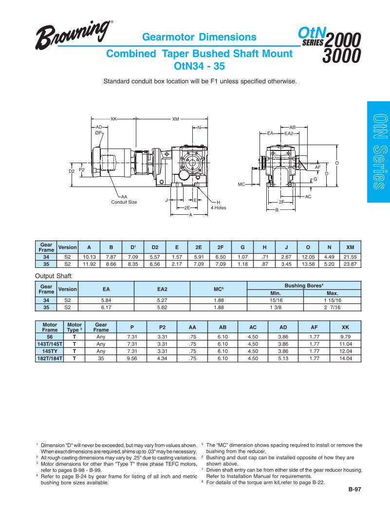
B-97
20003000
SERIESOtN
OtN Series
rotoMemarF
rotoMepyT 3
raeGemarF P 2P AA BA CA DA FA KX
65 T ynA 13.7 13.3 57. 01.6 05.4 68.3 77.1 97.9T541/T341 T ynA 13.7 13.3 57. 01.6 05.4 68.3 77.1 40.11
YT541 T ynA 13.7 13.3 57. 01.6 05.4 68.3 77.1 40.21T481/T281 T 53 65.9 43.4 57. 01.6 05.4 31.5 77.1 40.41
Output Shaft
Standard conduit box location will be F1 unless specified otherwise.
Gearmotor Dimensions
Combined Taper Bushed Shaft MountOtN34 - 35
1 Dimension "D" will never be exceeded, but may vary from values shown.When exact dimensions are required, shims up to .03" may be necessary.
2 All rough casting dimensions may vary by .25" due to casting variations.3 Motor dimensions for other than "Type T" three phase TEFC motors,
refer to pages B-98 - B-99.4 Refer to page B-24 by gear frame for listing of all inch and metric
bushing bore sizes available.
5 The “MC” dimension shows spacing required to install or remove thebushing from the reducer.
6 Bushing and dust cap can be installed opposite of how they areshown above.
7 Driven shaft entry can be from either side of the gear reducer housing.Refer to Installation Manual for requirements.
8 For details of the torque arm kit,refer to page B-22.
raeGemarF noisreV A B D1 2D E E2 F2 G H J O N MX
43 2S 31.01 78.7 90.7 75.5 75.1 19.5 05.6 70.1 17. 76.2 50.21 94.4 55.1253 2S 29.11 66.8 53.8 65.6 71.2 90.7 90.7 81.1 78. 54.3 85.31 02.5 78.32
raeGemarF noisreV AE 2AE CM 5
seroBgnihsuB 4
.niM .xaM43 2S 48.5 72.5 88.1 61/51 61/51153 2S 71.6 26.5 88.1 8/31 61/72
G
AFD
O
EA2AB
EAN
J
A
2E
MC
EAC
B
2F
D2
AAConduit Size H
4 Holes
XK
AD
P2
ØP
XM
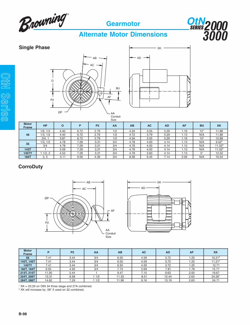
20003000
SERIESOtN
B-98
OtN Series
Gearmotor
Alternate Motor Dimensions
rotoMemarF
PH O P 2P AA BA CA DA FA UB KX
844/1,6/1 04.4 27.6 97.2 2/1 43.4 55.3 92.5 61.1 °21 88.112/1,3/1 04.4 27.6 97.2 2/1 27.4 97.3 92.5 31.1 A/N 88.11
1,4/3 78.3 27.6 97.2 2/1 43.4 55.3 92.5 61.1 °01 88.21
652/1,3/1 87.4 82.7 13.3 4/3 87.4 00.4 41.4 31.1 A/N 25.9 2
4/3 87.4 82.7 13.3 4/3 87.4 00.4 41.4 31.1 A/N 20.11 2
T341 1 90.5 82.7 13.3 4/3 87.4 00.4 41.4 31.1 A/N 20.11 2
YT541 2,2/11 35.4 82.7 13.3 4/3 87.4 38.3 41.4 31.1 °5 25.21T481 5,3 11.5 65.9 93.4 4/3 85.8 54.6 41.7 90.3 A/N 45.61
rotoMemarF
P 2P AA BA CA DA FA KX
65 14.7 44.3 4/3 05.6 95.4 27.3 52.1 12.01 2
T541,T341 14.7 44.3 4/3 05.6 95.4 27.3 52.1 12.11 2
YT541 14.7 44.3 4/3 05.6 95.4 27.3 52.1 17.21T481,T281 05.9 65.4 4/3 47.7 96.5 18.7 87.1 77.51T512,T312 00.11 44.5 1 74.9 51.7 36.9 00.2 76.91T652,T452 13.31 85.6 2/11 33.11 15.8 44.21 36.2 62.42 1
T682,T482 26.41 92.7 2/11 89.11 61.9 91.31 36.2 17.42
Single Phase
CorroDuty
1 XK = 23.29 on OtN 34 three stage and 27A combined.2 XK will increase by .58" if used on 32 combined.
AD
XK
ØP
P2
AC
AB
BU
AAConduitSize
AF
O
AB
AC
AF
ØP
P2
AAConduitSize
AD
XK

B-99
20003000
SERIESOtN
OtN Series
AWAC
AB
OAF
ØP
AZ
AY
AX
XK
AD
AV
P2
Gearmotor
Alternate Motor Dimensions
AD
XK
AC
AB
AF
ØP
P2
AAConduitSize
rotoMemarF
P 2P AA BA CA DA FA KX
65 88.7 83.3 4/3 97.6 13.5 73.4 87.1 51.31 2
T541,T341 88.7 83.3 4/3 97.6 13.5 73.4 87.1 09.31 2
T481,T281 05.9 65.4 4/3 07.7 97.5 57.7 52.2 07.51T512,T312 21.11 44.5 1 60.9 18.6 86.8 36.2 27.81T652,T452 63.31 85.6 2/11 08.01 22.8 18.11 31.3 56.32 1
T682,T482 26.41 03.7 2/11 81.31 26.9 00.31 88.3 25.42
rotoMemarF
rellortnoC O P 2P BA CA DA FA VA WA XA YA ZA KX
65 M1,1 47.7 33.7 76.3 54.6 19.5 53.4 16.5 52.2 59.2 26. 55. 35.8 97.9 2
T541,T341 M1,1 47.7 33.7 76.3 54.6 19.5 53.4 16.5 52.2 59.2 26. 55. 35.8 40.11 2
YT541 1 47.7 33.7 76.3 54.6 19.5 53.4 16.5 52.2 59.2 26. 55. 35.8 40.2165 M2 47.7 33.7 76.3 54.6 19.5 53.4 16.5 52.2 59.2 26. 55. 21.9 97.9T541 M2,2 47.7 33.7 76.3 54.6 19.5 53.4 16.5 52.2 59.2 26. 55. 21.9 40.11YT541 M2,2 47.7 33.7 76.3 54.6 19.5 53.4 16.5 52.2 59.2 26. 55. 21.9 40.21
T481,T2812 27.8 65.9 87.4 54.6 19.5 98.5 85.6 52.2 59.2 26. 55. 21.9 50.413 61.11 65.9 87.4 79.8 44.8 10.01 73.7 38.2 22.4 26. 55. 01.31 50.41
T312 3 99.11 52.11 89.4 79.8 44.8 37.11 11.8 38.2 22.4 26. 55. 01.31 51.61T512 3 99.11 52.11 89.4 79.8 44.8 32.31 11.8 38.2 22.4 26. 55. 01.31 56.71
rewoPtupnIegatloV/esahP
[email protected] 57.0 1 2ot5.1 5ot3 01ot5.7
511/1 M1 M2 - - - -032/1 M1 M1 M1 M2 - -032/3 1 1 1 2 3 -064/3 1 1 1 1 2 3
Explosion Proof
IntelliGear
1 XK = 22.58 on OtN 34 three stage and 27A combined.2 XK will increase by .58" if used on 32 combined.

20003000
SERIESOtN
B-100
OtN Series
Type "T" and "S" Motor with Brake
Dimensional Supplement
A
ØB
G (Conduit Size)
*E
rotoMemarF
euqroTekarB).sbl.tf( A B *E G
653 10.4 45.6 65.4 2/1
6 10.4 45.6 65.4 2/1
T541/T341
3 10.4 45.6 65.4 2/1
6 10.4 45.6 65.4 2/1
01 10.4 45.6 65.4 2/1
T481/T281 51 10.4 45.6 65.4 2/1
T312 52 83.7 83.9 57.8 2/1
T512 53 83.7 83.9 57.8 2/1
* Dimension "E" represents the additional length of motor with brake mounted. Add this amount to the gearmotor length "C".
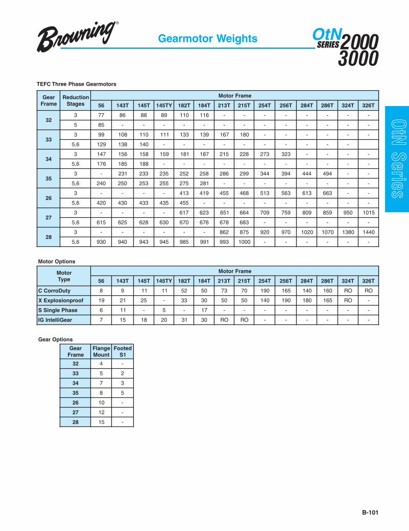
B-101
20003000
SERIESOtN
OtN SeriesGearmotor Weights
raeGemarF
noitcudeRsegatS
emarFrotoM
65 T341 T541 YT541 T281 T481 T312 T512 T452 T652 T482 T682 T423 T623
233 77 68 88 98 011 611 - - - - - - - -
5 58 - - - - - - - - - - - - -
333 99 801 011 111 331 931 761 081 - - - - - -
6,5 921 831 041 - - - - - - - - - -
433 741 651 851 951 181 781 512 822 372 323 - - - -
6,5 671 581 881 - - - - - - - - - - -
533 - 132 332 532 252 852 682 992 443 493 444 494 - -
6,5 042 052 352 552 572 182 - - - - - - - -
623 - - - - 314 914 554 864 315 365 316 366 - -
6,5 024 034 334 534 554 - - - - - - - - -
723 - - - - 716 326 156 466 907 957 908 958 059 5101
6,5 516 526 826 036 076 676 876 386 - - - - - -
823 - - - - - - 268 578 029 079 0201 0701 0831 0441
6,5 039 049 349 549 589 199 399 0001 - - - - - -
snoitpOrotoM
rotoMepyT
emarFrotoM
65 T341 T541 YT541 T281 T481 T312 T512 T452 T652 T482 T682 T423 T623
ytuDorroCC 8 9 11 11 25 05 37 07 091 561 041 061 OR OR
foorpnoisolpxEX 91 12 52 - 33 03 05 05 041 091 081 561 OR -
esahPelgniSS 6 11 - 5 - 71 - - - - - - - -
raeGilletnIGI 7 51 81 02 13 03 OR OR - - - - - -
snoitpOraeG
raeGemarF
egnalFtnuoM
detooF1S
23 4 -
33 5 2
43 7 3
53 8 5
62 01 -
72 21 -
82 51 -
TEFC Three Phase Gearmotors

B-102
OtN Series
OtN Helical BevelRight Angle
Speed Reducers
C-Face
Top Mount
Scoop Mount
Input Shaft

B-103
Speed Reducers 20003000
SERIESOtN
OtN Series
Type OtN Helical BevelSpeed ReducerFeatures...
Design Features
5
2
4
63
7
1. Gearcase Supplied Factory Filled with Synthetic Oil
• Wide temperature range and longer life.
2. Corrosion and Shock Resistant Cast Iron Housing
• One-piece, reinforced and ribbed for extra strength.
3. Series 3000 C-Face Reducers with Compact Quill Design
• Non-metallic liner to eliminate fretting.• Shorter design.• Two bearings for support.
4. Gears and Shafts of Nickel Chromium Molybdenum Steel
• Helical gearing is case hardened and then skived, superfinished or ground.• All gears heat shrunk on shafts or mounted on self-locking tapered shafts and keyed for high shock load
capability.
5. Normally Closed Breather with Multiple Locations (Optional OtN2000)
6. Double Lip Seals on Heat Treated, Plunge Ground Shafts
7. Magnetic Drain Plug Standard
1

20003000
SERIESOtN
B-104
OtN Series
Table of Contents
Section PageMounting Versatility and Size Range ........................................................................................................... B-105Speed Reducer Selection ............................................................................................................... B-106 - B-107Catalog Nomenclature .................................................................................................................... B-108 - B-109Gearmotor Mounting Positions .................................................................................................................... B-110Gearmotor Output Brackets and Shafts ...................................................................................................... B-111Modifications, Options and Accessories ...................................................................................................... B-112AC Motors ..................................................................................................................................................... B113Torque Reaction Arms .................................................................................................................... B-114 - B-115Tapered Bushing Selections ........................................................................................................................ B-116AGMA Application Classifications................................................................................................... B-117 - B-119Speed Reducer Selection Tables .................................................................................................... B-120 - B-125Dimension Prints
C-Face Reducers Output Shafted Foot Mount ........................................................................ B-126 - B-129C-Face Reducers Output Shafted Flange Mount ..................................................................... B-130 - B-133C-Face Reducers Finished Bore Hollow Shaft ........................................................................ B-134 - B-137C-Face Reducers Finished Bore Hollow Shaft Face Mount .................................................... B-138 - B-141C-Face Reducers Finished Bore Hollow Shaft Flange Mount ................................................. B-142 - B-145C-Face Reducers Taper Bushed Shaft Mount ......................................................................... B-146 - B-147Input Shaft Reducers Output Shafted Foot Mount ................................................................... B-148 - B-149Input Shaft Reducers Output Shafted Flange Mount ............................................................... B-150 - B-153Input Shaft Reducers Finished Bore Hollow Shaft ................................................................... B-154 - B-155Input Shaft Reducers Finished Bore Hollow Shaft Face Mount ............................................... B-156 - B-159Input Shaft Reducers Finished Bore Hollow Shaft Flange Mount ........................................... B-160 - B-163Input Shaft Reducers Taper Bushed Shaft Mount .................................................................... B-164 - B-165Scoop Mount Reducers Output Shafted Foot Mount ............................................................... B-166 - B-168Scoop Mount Reducers Output Shafted Flange Mount ........................................................... B-169 - B-171Scoop Mount Reducers Finished Bore Hollow Shaft ............................................................... B-172 - B-174Scoop Mount Reducers Finished Bore Hollow Shaft Face Mount ........................................... B-175 - B-177Scoop Mount Reducers Finished Bore Hollow Shaft Flange Mount ........................................ B-178 - B-180Scoop Mount Reducers Taper Bushed Shaft Mount ............................................................................. B-181Top Mount Reducers Output Shafted Foot Mount ................................................................................ B-182Top Mount Reducers Finished Bore Hollow Shaft ................................................................................ B-183Top Mount Reducers Finished Bore Hollow Shaft Face Mount ............................................................ B-184Top Mount Reducers Taper Bushed Shaft Mount ................................................................................. B-185
Reducer Weights ......................................................................................................................................... B-186Lubrication ................................................................................................................................................... B-187Gearmotor - Typical Motor Performance Data ........................................................................................ E-1 - E-4IntelliGear Technical Specifications ........................................................................................................ E-5 - E-9NEMA Standard Dimensions ......................................................................................................................... E-10General Information ....................................................................................................................................... E-11Standard Terms and Conditions of Sale ........................................................................................................ E-12
Speed Reducers

B-105
20003000
SERIESOtN
OtN Series
Foot MountFrames 2 – 8Solid Shaft
Max. 88,000 lb-in
NEMA C-Face56C to 326TC
Input Shaft
Top MountFrames 3 - 5**
56 to 256T
Scoop MountFrames 3 - 8*
56 to 326T
C-Face MotorsFrames 56C - 326TC
Backstop Options***
Shaft MountTorque ArmFrames 2-8Hollow Shaft
Tapered Bushed (Fr 2-5)Max. 88,000 lb-in
Face MountFrames 2-8Hollow Shaft
Max. 88,000 lb-in
Flange MountFrames 2-8Solid Shaft
Hollow ShaftMax. 88,000 lb-in
High Ratio CombinedFrames 2-8 - All Styles
Max. 88,000 lb-in
Speed Reducers
Mounting Versatility and Size Range
* Not available for frames 2 - 5, 5-stage or frames 4 - 6, 6-stage.** Only available for frames 3 - 5, 3-stage.***Not available for frames 3245 and 3365A. Available input shaft or scoop mount only for frames 6 - 8.

20003000
SERIESOtN
B-106
OtN Series emirPrevoM
fosruoHnoitarepO
mrofinUdaoL
U
etaredoMdaoLkcohS
M
yvaeHkcohS
daoLV
cirtcelErotoM
3-0 08.0 00.1 05.101-3 00.1 52.1 57.142-01 52.1 05.1 00.2
lanretnInoitsubmoC
enignE
3-0 00.1 52.1 57.101-3 52.1 05.1 00.242-01 05.1 57.1 52.2
Speed Reducers Selection
1. Application DataBottling conveyor, 24-hrs/dayoperation. Requires right anglehollow shaft mounted speed reducerto be mounted directly to theconveyor drive shaft with a torquearm. The customer prefers ac-face mounted motor.
Motor rating: 5 HP, 1750 RPM, 184TC FootlessFrame, 230/460 VAC, 3-Phase, 60Hz, TEFC
Output speed: 44 rpm2. Size Selection
Nominal Ratio: Locate nominal rpm closest to44 rpm. 40:1 nominal ratio isthe proper selection.
Service Factor: Using AGMA applicationclassification chart (pageB-117) under the “Brewing andDistilling” heading, bottlingmachinery that operates over10 hours/day should have a1.25 service factor.
Rating Req’d: Minimum reducer ratingrequired is P = Pm x SFP = 5 HP x 1.25 = 6.25 HP
Catalog Rating:
1. Input HP• Based on application data.
2. Speed/Ratio• Obtain either desired output speed (rpm) or gearbox
ratio based on application.3. Service Factor
• Determine the required service factor using eitherthe AGMA application classification chart (pagesB-117 - B-119), or the duration of operation, loadtype, and drive type with the table below:
Step 1• Locate speed reducer selection tables (pages B-120
- B-125) based on input speed to gearbox.Step 2
• Choose the nominal ratio appropriate for the speedsrequired.
Step 3• Select the gear unit size for the chosen ratio and the
known input speed so that the mechanical powerrating P (hp) satisfies the following:
P ≥ Pm • SF
P = mechanical power rating (hp) of gearbox
Pm = motor power (hp)
SF = required service factor
Note: Size selection based on absorbed power (Pa) orabsorbed torque (Ta) at the low speed shaft instead ofmotor power (Pm) is allowed when the former is knownwith sufficient accuracy and if the number of start opera-tions is limited. When Ta is applied in size selection, verifyif:
T = torque rating (in. lbs.) at low speed shaftTa = absorbed torque (in. lbs.) at low speed shaftSF = required service factor
T ≥ Ta • SF
Size Selection (cont.)Selection Information
Size Selection
Example
Step 4• Verify overhung load ratings where required
(see page B-107).
Exact ratio Gear Frame 39.9 3473
Input H.P. Output Torque 9.96 13453
Selection: OtN3473 is rated 9.96 HP input/13453 lb-in output with 39.9:1 ratio.1750 rpm / 39.9 = 43.9 rpm output speed.9.96 / 5 = 1.99 SF.
3. Catalog DesignationReducer: OtN-3473-S2-B33C-40-U-184TC
(See page B-108.)Torque Arm: ROC400KT001 (See page B-114.)
4. Motor Model Number SelectionPart Number: U5S2ACR
(See Page B-113.)Specifications:5 HP, 1750 rpm, 184TC
Footless Frame, 208-230/460VAC, 3-Phase, 60 Hz, TEFC

B-107
20003000
SERIESOtN
OtN Series
When a sprocket, sheave, pulley, or pinion is mounted on thetake-off shaft of a reducer, it is necessary to calculate theoverhung load. This calculated load must be compared withthe gearbox capacity listed to make sure the gearbox will notbe overloaded. To calculate the overhung load you need toknow the torque or horsepower at the take-off shaft and thelocation along the shaft at which the load is applied.
A. If torque is known:
OHL =
B. If horsepower is known:
OHL =
T x K x LLFr
Where:OHL = Overhung load (pounds)T = Torque (in. lbs.)r = Radius of driving member (in.)HP = HorsepowerK = Drive type factorLLF = Load location factor
63025 x HP x K x LLFRPM x r noitacoLdaoL FLLfoeulaV
noisnetxetfahsfodnE 02.1noisnetxetfahsforetneC 00.1redluohsnoisnetxetfahS 08.0
rebmeMgnivirD KfoeulaVevirDniahC 00.1
noiniP 52.1tleBgnimiT 52.1
tleB-V 05.1tleBtalF 05.2
Overhung Load (lbs.)
Speed Reducers
Overhung Load Capacities
OHL capacities above are calculated at gear capacity rounded to the closest motor HP at mid shaft. For capacity when HP is known, refer to gearmotor selectiontables.
tuptuOmpr
emarF
23 33 43 53 62 72 82
571-151 528 2931 3561 5652 - - -
051-101 438 9451 7071 5182 0664 0007 05301
001-15 209 7371 2981 9333 0565 0058 00121
05-13 8411 0902 5342 0014 0606 00301 00121
03-61 0941 0902 5782 0014 0606 00211 00121
51-5 0941 0902 5782 0014 0606 00211 00121
5< 0941 0902 5782 0014 0606 00211 00121

20003000
SERIESOtN
B-108
OtN Series
gninworB-thgiR
elgnA-lacileH
leveB
seireSrecudeR
eziSsegatS
tooF&tfahSsnoisnemiD 1
gnitnuoMnoitisoP
tuptuOegnalF/ecaF
tfeL-thgiRmorFdeweiV
dnEtupnI
tfahStuptuOnoitarugifnoC
morfdeweiVdnEtupnI
lanimoNraeGoitaR
tupnIepyT
emarFrotoMtpecxEllA(tfahStupnI
)epyT
snoitacifidoM
23
33
43
53
62
72
82
4
6
7
8
0
0
0
=3
=A5ro5
=6
=3
=A5
=A6
segats3
segats5denibmoc
segats6denibmoc
segats3
segats5denibmoc
segats6denibmoc
=1S
=2S
=1S
0002NtOtnemecalper
snoisnemid
yrtsudnIegnahcretnisnoisnemid
seireSllAstinU0002
=B
=P
=H
=T
=V
=W
tnuomroolF
gnilieCtnuom
,tnuomllaWtfeltupni
,tnuomllaWthgirtupni
tupnIpulacitrev
tupnIlacitrev
nwod
=3
=4
=5
=6
dradnatSdnuor
tnuomecaF
dradnatSnoisnemid
tnuomegnalf
etanretlAnoisnemid
tnuomegnalf
=G
=D
=X
=C
=B
=S
thgirtfahS
tfeltfahS
tfahslauD
dehsiniFerob
derepaTdehsub
wercSroyevnocdnatfahs
retpada
=4.221:4.22
esUlanimon
oitardetceles
morfrecudernoitceles
selbat
tupnI=PAtfahS
tupnI=DAhtiwtfahSpotskcaB
poocS=PStnuoM
poocS=DShtiwtnuoM
potskcaB
ecaF-C=U
-C=DUhtiwecaFpotskcaB
poT=MTtnuoM
poT=DMThtiwtnuoM
potskcaB
ecaF-CCT623-C65
tnuoMpoocST623-T341
tnuoMpoTT682-65
morftceleSsnoitacifidomegapnodetsil
211-B
Output Flange Sizes
Ser
ies
2000
Ser
ies
3000
OtN • 34 7 3 • S2 • B 33 G • 22.4 • U • 145TC • M11
Speed Reducers
Ordering
See pages B-110 and B-111
1 Shaft and critical mounting dimensions match either OtN2000 or SEW “K” Series units. These dimensions include the mounting base, output flanges,output shaft diameter, distance from housing center line to shaft tip, and output quill diameter. B14 mounting faces and overall product envelope (height,width, depth) do NOT match.
SEW is believed to be a trade name of SEW-Eurodrive GMBH & Co. and is NOT owned or controlled by Emerson Power Transmission.Emerson Power Transmission Corporation cannot and does not represent or warrant the accuracy of this information.
)mm(snoisnemiDegnalFDB 002 052 003 053 004 054 055KA 031 081 032 052 003 053 054JA 561 512 562 003 053 004 005
emarFraeG rotangiseDrebmuNtraPegnalFtuptuO23 5 633 5 643 5 653 5 662 572 582 5

B-109
20003000
SERIESOtN
OtN SeriesSpeed Reducers
Catalog Nomenclature
C-Face Frames
Scoop Mount Frames
Top Mount Frames
srecudeRecaF-C0003/0002NtO
emarFrotoM C65CT341CT541
CT281CT481
CT312CT512
CT452CT652
CT482CT682
CT423CT623
emarFraeG3423 1:061-1:01 1:061-1:01 1:001-1:015423 1:005,4-1:081 1:008,2-1:0813633 1:061-1:01 1:061-1:01 1:041-1:01 1:09-1:015633 1:003,6-1:081 1:000,4-1:081 1:009-1:0813743 1:061-1:01 1:061-1:01 1:061-1:01 1:001-1:01 1:001-1:01
6743/5743 1:000,01-1:081 1:000,01-1:081 1:008,2-1:0813853 1:061-1:52 1:061-1:52 1:061-1:52 1:061-1:41 1:521-1:01 1:65-1:01
6853/5853 1:000,01-1:081 1:000,01-1:081 1:000,4-1:0813062 1:001-1:5.21 1:001-1:5.21 1:001-1:5.21 1:001-1:5.21 1:001-1:5.21
6062/5062 1:000,01-1:521 1:000,01-1:521 1:000,01-1:521 1:005-1:521 1:005-1:5213072 1:001 1:001-1:54 1:09-1:4.22 1:05-1:5.21
6072/5072 1:000,01-1:041 1:000,01-1:041 1:000,01-1:041 1:005-1:041 1:005-1:0413082 1:001-1:08 1:001-1:5.53 1:09-1:52 1:36-1:5.21
6082/5082 1:000,9-1:211 1:000,9-1:211 1:000,9-1:211 1:005,2-1:211 1:036-1:211 1:082-1:211
srecudeRtnuoMpoocS0003/0002NtO
emarFrotoM 65T341T541
T281T481
T312T512
T452T652
T482T682
T423T623
emarFraeG3423 elbaliavAtoN5423 elbaliavAtoN3633 X X - - - - -5633 elbaliavAtoN3743 X X X - - - -5743 elbaliavAtoN6743 elbaliavAtoN3853 - X X X - - -5853 elbaliavAtoN6853 elbaliavAtoN3062 - X X X X X -5062 - X - - - - -6062 elbaliavAtoN3072 - - X X X X X5072 - X X X - - -6072 - X - - - - -3082 - - - - X X X5082 - X X X X - -6082 - X X - - - -
srecudeRtnuoMpoT0003/0002NtO
emarFrotoM 65T341T541
T281T481
T312T512
T452T652
emarFraeG3423 elbaliavAtoN5423 elbaliavAtoN3633 X X X - -5633 elbaliavAtoN3743 X X X X -5743 elbaliavAtoN6743 elbaliavAtoN3853 - X X X X5853 elbaliavAtoN6853 elbaliavAtoN3062 elbaliavAtoN5062 elbaliavAtoN6062 elbaliavAtoN3072 elbaliavAtoN5072 elbaliavAtoN6072 elbaliavAtoN3082 elbaliavAtoN5082 elbaliavAtoN6082 elbaliavAtoN

20003000
SERIESOtN
B-110
OtN Series
Speed Reducer Position (defined by a letter)
Speed Reducers
Mounting Position
H
VW
P
T
B

B-111
20003000
SERIESOtN
OtN Series
Output Bracket Options
Example: Standard floor mount, shaft output on right (facing reducer input).
BFloor Mount
3Right Output Endshield
3Left Output Endshield
GShaft Output on Right
Output Shaft Arrangement
NtOemarF
detnuoMtooF detnuoMecaF detnuoMegnalF detnuoMtfahStfahSdiloS tfahSwolloH tfahSdiloS tfahSwolloH wolloH dehsuB
G33 D33 X33 *C33 C43 C34 *C44 G35 D53 X55 C35 C53 *C55 *C33 *B332333435362 -72 -82 -
If shaded, the alternative flange "6" is also available.This is available at normal lead-times.This item is available at production lead-times.
- Refer to office for design review.* This design allows entry of driven shaft from either side of gear housing.
Speed Reducers
Brackets and Shafts
Note: Viewed reducer input, define each endshield per drawing.
Define in order shown
Options
Taper Bushed = B*Left = D Right = G Left / Right = X Hollow Bore = C* Bushing may be field reversed to opposide side.
Plain = 3 Flanged = 5 or 6Face = 4

20003000
SERIESOtN
B-112
OtN Series
M11 Corro-DutyCorro-Duty gearmotors are designed for applications in foodprocessing, chemical, poultry and any other industries that willbe subjected to extreme humidity, washdown, steam,detergents and mild acids. The Corro-Duty option includes anormally closed breather in the gear case. The exterior of theentire unit is then painted in one of the two options chosen atorder entry.
Option #1 - Corro-Duty grey• 3 step paint system using 316 stainless
steel paint• Light grey semigloss finish• USDA and FDA approved
Option #2 - Corro-Duty white• 2 step paint system using epoxy paint• White gloss finish• USDA and FDA approved
M12 Normally Closed BreatherThis breather protects against lubricant contamination inapplications with flying dust, lint or washdown. A normallyclosed breather is standard on frames sizes 2 through 5, orit may be added to frames 6 though 8 by specifying thisoption.
M13 NPT AdapterThese adapters convert metric threads of breather, drain and/oroil level holes in the reducer to standard NPT threads. They arerequired for customer additions of site glasses, sight tubes,special breathers and other plumbing accessories. Theadapter(s) is supplied loose for mounting by others.
Speed Reducers
Modifications, Options and Accessories
Face and Flanged Output(Designated under Brackets and Shafts)Gearmotors with faced or flanged outputs are available fromstock. Refer to page B-108 and individual dimension pagesfor options available based on gear frame size.
Synthetic OilOtN gearmotors are supplied factory-filled with a premiumsynthetic oil. Refer to page B-187 for complete details oflubricants.
raeGemarF eziS rebmuNtraP
5-2 TFPN"4/1 61263408-6 TFPN"4/3 8126340
M18 Oil Level View PortThis clear port is installed in place of the oil level plug. Itallows maintenance personnel a convenient means ofchecking for proper oil level without removing plugs. ProperView Port part numbers are:
raeGemarF eziS rebmuNtraP
5-2 elaMPPSB"4/1 63953408-6 elaMPPSB"4/3 8395340
M15 Export BoxingExport boxing can be provided for "underdeck" transport. Whenthe quantity of OtN gearmotors exceeds five units, refer to thesales department for the most economical accommodations.
M16 Special NameplateUnits can be provided with limited, additional, specialinformation on the standard product nameplate. Whenrequested, a special nameplate may be provided and stampedwith custom markings.
M17 Coupling GuardFor scoop mount series, this kit includes cover, base andhardware.

B-113
20003000
SERIESOtN
OtN SeriesAC Motors
Selection
C-Face Footless
C-Face footed motor.
Rigid Base Mount
Unimount, 841 Plus and eLine are registered trademarks of Emerson Electric Co.
Emerson Power Transmission Corporation cannot and does not represent or warrant the accuracy of this information.
PH emarF
tnuominU ®
CFETCAV064/032-802
zH06/hP-3ycneiciffE.dtS
tnuominUCFET
CAV575zH06/hP-3
ycneiciffE.dtS
tnuominUCFET
CAV064/032-802zH06/hP-3
tneiciffEygrenE
tnuominUCFET
CAV575zH06/hP-3
tneiciffEygrenE
sulP148 ®
ytuD148EEEICAV064
zH06/hP-3tneiciffEmuimerP
eniLe ®
ytuDereveSCAV064/032-802
zH06/hP-3tneiciffEygrenE
eniLeytuDereveS
CAV575zH06/hP-3
tneiciffEygrenE
4/1 C65 RCA2S41U
3/1 C65 RCA2S31U
2/1 C65 RCA2S21U RCG2S21U
4/3 C65 RCA2S43U RCG2S43U
1CT341 RCA2S1U RCG2S1U RCC2P1P8 CD2E1TLE CG2E1TLE
C65 RCFA2S1U
2/11CT541 RCA2S23U RCG2S23U RCC2P23P8 CD2E23TLE CG2E23TLE
C65 RCFA2S23U RCFG2S23U
2CT541 RCA2S2U RCG2S2U RCC2P2P8 CD2E2TLE CG2E2TLE
C65 RCFA2S2U
3 CT281 RCA2S3U RCG2S3U RCD2E3U RCG2E3U RCC2P3P8 CD2E3TLE CG2E3TLE
5 CT481 RCA2S5U RCG2S5U RCD2E5U RCG2E5U RCC2P5P8 CD2E5TLE CG2E5TLE
2/17 CT312 RCA2S7U RCG2S7U RCD2E7U RCG2E7U RCC2P7P8 CD2E7TLE CG2E7TLE
01 CT512 RCA2S01U RCG2S01U RCD2E01U RCG2E01U RCC2P01P8 CD2E01TLE CG2E01TLE
51 CT452 RCA2S51U RCD2E51U RCG2E51U CD2E51TLE CG2E51TLE
02 CT652 RCA2S02U RCD2E02U RCG2E02U CD2E02TLE CG2E02TLE
52 CT482 RCA2S52U RCD2E52U RCG2E52U CD2E52TLE CG2E52TLE
03 CT682 RCA2S03U RCD2E03U RCG2E03U CD2E03TLE CG2E03TLE
PH emarF
tnuominUCFET
CAV064/032-802zH06/hP-3
ygrenEtneiciffE
tnuominUCFET
CAV575zH06/hP-3
ygrenEtneiciffE
tnuominUCFET
CAV002zH06/hP-3
ygrenEtneiciffE
ytuDelitsoHCFET
CAV064/032zH06/hP-3
ygrenEtneiciffE
ytuDelitsoHCFET
CAV575zH06/hP-3
ygrenEtneiciffE
ytuDelitsoHCFET
CAV002zH06/hP-3
ygrenEtneiciffE
eniLeytuDereveS
CAV064/032-802zH06/hP-3
ygrenEtneiciffE
eniLeytuDereveS
CAV575zH06/hP-3
ygrenEtneiciffE
1 T341 D2E1U G2E1U H2E1U D2E1H G2E1H H2E1H D2E1TLE G2E1TLE
2/11 T541 D2E23U G2E23U H2E23U D2E23H G2E23H H2E23H D2E23TLE G2E23TLE
2 T541 D2E2U G2E2U H2E2U D2E2H G2E2H H2E2H D2E2TLE G2E2TLE
3 T281 D2E3U G2E3U H2E3U D2E3H G2E3H H2E3H D2E3TLE G2E3TLE
5 T481 D2E5U G2E5U H2E5U D2E5H G2E5H H2E5H D2E5TLE G2E5TLE
2/17 T312 D2E7U G2E7U H2E7U D2E7H G2E7H H2E7H D2E7TLE G2E7TLE
01 T512 D2E01U G2E01U H2E01U D2E01H G2E01H H2E01H D2E01TLE G2E01TLE
51 T452 D2E51U G2E51U H2E51U D2E51H G2E51H H2E51H D2E51TLE G2E51TLE
02 T652 D2E02U G2E02U H2E02U D2E02H G2E02H H2E02H D2E02TLE G2E02TLE
52 T482 D2E52U G2E52U H2E52U D2E52H G2E52H H2E52H D2E52TLE G2E52TLE
03 T682 D2E03U G2E03U H2E03U E2E03H G2E03H H2E03H D2E03TLE G2E03TLE
04 T423 E2E04H G2E04H H2E04H D2E04TLE
05 T623 E2E05H G2E05H H2E05H D2E05TLE

20003000
SERIESOtN
B-114
OtN Series
Torque Reaction Arm
Speed Reducers
Mounting Accessories
ØAJ
O
ØBF
90°
ØFU
Anchoring of theTorque Arm
GA
180° 0°
270°
G
AK
NtOemarF tiK#DItraP G O JA KA FB UF AG
23 100TK002COR 36. 811.5 49.3 051.3 34. 78. 97.
33 100TK003COR 19. 478.7 48.4 739.3 15. 062.1 01.1
43 100TK004COR - 248.9 89.5 811.5 15. 062.1 19.
53 100TK005COR - 502.21 84.7 201.6 76. 062.1 89.
Series 3000
• Torque arm can be assembled in any of the threepositions shown in the drawing above relative to theinput (motor) when called out on the order.
• If torque arm is requested on an assembly order andno mounting position is called for, the default positionis 0°.
• Torque arm can be affixed to either side of the 33C or33B gear housing.

B-115
20003000
SERIESOtN
OtN Series
raeGemarF
traPrebmuN A 1D G 1H 2H .xam3H L 1L 2L 1S
.nim
62 9746890 89.31 57. 05.2 16.31 05.4 05.1 38.53 64.72 80.62 18.0
72 9746890 45.61 57. 05.2 95.41 05.4 05.1 38.53 81.62 08.42 18.0
82 0846890 80.02 88. 00.4 76.81 00.6 88.1 13.34 96.13 21.03 49.0
A
L2
L
L1
H2
D1
S1
G
H3
H1
Torque Reaction Arm
Speed Reducers
Mounting Accessories
Series 2000
• Torque arm can be assembled with attachment pointon the input side or 180° opposite this, as shownabove.
• Torque arm can be attached onto feet on either sideof the gear housing as you face opposite the input(motor).

20003000
SERIESOtN
B-116
OtN Series
Stabilizer Ring
Tapered Bushings
Each Series 3000 OtN can be ordered with a TaperedBushed Output. This “33B” mounting configuration willinclude the appropriate bushing kit unassembled whena bore is defined at order entry. The table below showsthe various stocked bushing bores for each OtN framethat can be specified. Each bushing kit is supplied withbushing, hardware for mounting and a stabilizer ring. Ifbushings are required as a spare or bore changed inthe field, refer to the OtN 3000 frame and select therequired kit from below.
NtOemarF
.aeMtinU
gnihsuB.oN
eroBtaesyeKtfahS
deriuqeRepyT
rezilibatShtdiWgniR
euqroTtloB thgieW).sbl(eziStloB .sbl-.tF
2333
hcnI
210PBT701 4/3 8/73x23/3x61/3 1
397.0 4/11x81-61/5 61
6.2410PBT701 8/7 8/73x23/3x61/3 1 5.2510PBT701 61/51 8/73x8/1x4/1 2 4.2001PBT701 1 8/73x8/1x4/1 2 3.2101PBT701 61/11 8/73x8/1x4/1 2 1.2201PBT701 8/11 8/73x8/1x4/1 2 0.2
301PBT701 61/31 8/73x8/1x4/1 2 9.1401PBT701 4/11 8/73x8/1x4/1 2 8.1501PBT701 61/51 8/73x23/5x61/5 2 6.1601PBT701 8/31 8/73x23/5x61/5 2 5.1701PBT701 61/71 8/73x61/3x8/3 2 5.1
*cirteM MM03PBT701 mm03 )mm(49x4x8 2 9.1MM53PBT701 mm53 )mm(49x5x01 2 5.1
43
hcnI
510PBT511 61/51 8/14x8/1x4/1 1
558.0 4/11x61-8/3 92
6001PBT511 1 8/14x8/1x4/1 1 9.5101PBT511 61/11 8/14x8/1x4/1 1 7.5201PBT511 8/11 8/14x8/1x4/1 1 6.5301PBT511 61/31 8/14x8/1x4/1 1 4.5
401PBT511 4/11 8/14x8/1x4/1 1 3.5501PBT511 61/51 8/14x23/5x61/5 2 1.5601PBT511 8/31 8/14x23/5x61/5 2 8.4701PBT511 61/71 8/14x61/3x8/3 2 7.4801PBT511 2/11 8/14x61/3x8/3 2 4.4
011PBT511 8/51 8/14x61/3x8/3 2 0.4111PBT511 61/111 8/14x61/3x8/3 2 7.3211PBT511 4/31 8/14x61/3x8/3 2 5.3411PBT511 8/71 8/14x4/1x2/1 2 1.3511PBT511 61/511 8/14x4/1x2/1 2 7.2
*cirteM MM04PBT511 mm04 )mm(001x5x21 2 0.4MM54PBT511 mm54 )mm(001x5.5x41 2 5.3
53
hcnI
601PBT702 8/31 8/15x23/5X61/5 1
040.1 4/11X61-8/3 92
6.93.91.95.8
701PBT702 61/71 8/15X61/3X8/3 1801PBT702 2/11 8/15X61/3X8/3 1011PBT702 8/51 8/15X61/3X8/3 2
111PBT702 61/111 8/15X61/3X8/3 2 3.89.73.79.6
211PBT702 4/31 8/15X61/3X8/3 2411PBT702 8/71 8/15X4/1X2/1 2511PBT702 61/511 8/15X4/1X2/1 2
002PBT702 2 8/15X4/1X2/1 2 6.69.55.51.59.3
202PBT702 8/12 8/15X4/1X2/1 2302PBT702 61/32 8/15X4/1X2/1 2402PBT702 4/12 8/15X4/1X2/1 2702PBT702 61/72 8/15X61/5X8/5 2
*cirteMMM05PBT702 mm05 )mm(521x5.5x41 2 6.6
5.4MM06PBT702 mm06 )mm(521x7x81 2
* Metric bushings have metric bores and require metric keyseats as shown in mm.

B-117
20003000
SERIESOtN
OtN SeriesSpeed Reducers
AGMA Application Classifications
Application Service Factor Application Service Factor
Agitators (Mixers)Pure Liquids — 1.00 1.25Liquids & Solids 1.00 1.25 1.50Liquids - Variable Density 1.00 1.25 1.50
BlowersCentrifugal 1.00 1.25 —Lobe 1.00 1.25 1.50Vane — 1.00 1.25
Brewing and DistillingBottling Machinery — 1.00 1.25Brew Kettles, Continuous Duty — 1.00 1.25Cookers - Continuous Duty — 1.00 1.25Mash Tubs - Continuous Duty — 1.00 1.25Scale Hoppers, Frequent Starts 1.00 1.25 1.50
Can Filling Machines — 1.00 1.25
Car Dumpers 1.25 1.50 1.75
Car Pullers 1.00 1.25 1.50
Clarifiers — 1.00 1.25
Classifiers 1.00 1.25 1.50
Clay Working IndustryBrick Press 1.25 1.50 1.75Briquette Machine 1.25 1.50 1.75Pug Mill 1.00 1.25 1.50
Compactors 1.50 1.75 2.00
CompressorsCentrifugal — 1.00 1.25Lobe 1.00 1.25 1.50Reciprocating, Multi - Cylinder 1.00 1.25 1.50Reciprocating, Single - Cylinder 1.25 1.50 1.75
Conveyors - General PurposeUniformly Loaded or Fed — 1.00 1.25Not Uniformly Fed 1.00 1.25 1.50Reciprocating or Shaker 1.25 1.50 1.75
CranesDry Dock
Main Hoist 1.25 1.50 1.75Auxiliary 1.25 1.50 1.75Boom Hoist 1.25 1.50 1.75Slewing Drive 1.25 1.50 1.75Traction Drive 1.50 1.50 1.50
ContainerMain Hoist Refer to Application Engineering
Cranes (Continued)Boom Hoist Refer to Application EngineeringTrolley Drive Refer to Application Engineering
(Gantry Drive)(Traction Drive) Refer to Application Engineering
Mill DutyMain Refer to Application EngineeringAuxiliary Refer to Application EngineeringBridge & Trolley Travel Refer to Application Engineering
Industrial DutyMain 1.25 1.50 1.75Auxiliary Refer to Application EngineeringBridge & Trolley Travel Refer to Application Engineering
CrusherStone or Ore 1.50 1.75 2.00
DredgesCable Reels 1.00 1.25 1.50Conveyors 1.00 1.25 1.50Cutter Head Drives 1.25 1.50 1.75Pumps 1.00 1.25 1.50Screen Drives 1.25 1.50 1.75Stackers 1.00 1.25 1.50Winches 1.00 1.25 1.50
ElevatorsBucket 1.00 1.25 1.50Centrifugal Discharge — 1.00 1.25Escalators Refer to Application EngineeringFreight Refer to Application EngineeringGravity Discharge — 1.00 1.25
ExtrudersGeneral 1.25 1.25 1.25Plastics
(a) Variable Speed Drive 1.50 1.50 1.50(b) Fixed Speed Drive 1.75 1.75 1.75
Rubber(a) Continuous Screw Operation 1.50 1.50 1.50(b) Intermittent Screw Operation 1.75 1.75 1.75
FansCentrifugal — 1.00 1.25Cooling Towers Refer to Application EngineeringForced Draft 1.25 1.25 1.25Induced Draft 1.00 1.25 1.50Industrial & Mine 1.00 1.25 1.50
Up to Up to Over3 10 10
hrs/day hrs/day hrs/day
Up to Up to Over3 10 10
hrs/day hrs/day hrs/day

20003000
SERIESOtN
B-118
OtN Series
FeedersApron — 1.25 1.50Belt 1.00 1.25 1.50Disc — 1.00 1.25Reciprocating 1.25 1.50 1.75Screw 1.00 1.25 1.50
Food IndustryCereal Cooker — 1.00 1.25Dough Mixers 1.00 1.25 1.50Meat Grinders 1.00 1.25 1.50Slicers 1.00 1.25 1.50
Generators and Exciters — 1.00 1.25
Hammer Mills 1.50 1.50 1.75
HoistsHeavy Duty 1.25 1.50 1.75Medium Duty 1.00 1.25 1.50Skip Hoist 1.00 1.25 1.50
Laundry Tumblers 1.00 1.25 1.50
Laundry Washers 1.00 1.25 1.50
Lumber IndustryBarkers
- Spindle Feed 1.25 1.25 1.25- Main Drive 1.50 1.50 1.50
Conveyors- Burner 1.25 1.25 1.50- Main or Heavy Duty 1.50 1.50 1.50- Main Log 1.50 1.50 1.50- Re-Saw, Merry-Go-Round 1.25 1.25 1.50- Slab 1.50 1.50 1.75- Transfer 1.25 1.25 1.50
Chains - Floor 1.50 1.50 1.50 - Green 1.50 1.50 1.50
Cut-Off Saws- Chain 1.50 1.50 1.50- Drag 1.50 1.50 1.50
Debarking Drums 1.50 1.50 1.75Feeds
- Edger 1.25 1.25 1.50- Gang 1.50 1.50 1.50- Trimmer 1.25 1.25 1.50
Log Deck 1.50 1.50 1.50Log Hauls - Incline-Well Type 1.50 1.50 1.50Log Turning Devices 1.50 1.50 1.50Planner Feed 1.25 1.25 1.25Planer Tilting Hoists 1.50 1.50 1.50Rolls - Live-Off Bearing.-Roll Cases 1.50 1.50 1.50Sorting Table 1.25 1.25 1.50Tipple Hoist 1.25 1.25 1.50Transfers
- Chain 1.50 1.50 1.50- Causeway 1.50 1.50 1.50
Tray Drives 1.25 1.25 1.50Veneer Lathe Drives Refer to Application Engineering
Metal MillsDraw Bench Carriage & Main Drive 1.00 1.25 1.50Runout Table
Non-reversingGroup Drives 1.00 1.25 1.50Individual Drives 1.50 1.50 1.75
Reversing 1.50 1.50 1.75Slab Pushers 1.25 1.25 1.50Shears 1.50 1.50 1.75Wire Drawing 1.00 1.25 1.50Wire Winding Machine 1.00 1.25 1.50
Metal Strip Processing MachineryBridles 1.25 1.25 1.50Coilers & Uncoilers 1.00 1.00 1.25Edge Trimmers 1.00 1.25 1.50Flatteners 1.00 1.25 1.50Loopers (Accumulators) 1.00 1.00 1.00Pinch Rolls 1.00 1.25 1.50Scrap Choppers 1.00 1.25 1.50Shears 1.50 1.50 1.75Slitters 1.00 1.25 1.50
Mills, Rotary TypeBall & Rod
Spur Ring Gear 1.50 1.50 1.75Helical Ring Gear 1.50 1.50 1.50Direct Connected 1.50 1.50 1.75
Cement Kilns 1.50 1.50 1.50Dryers & Coolers 1.50 1.50 1.50
Mixers, Concrete 1.00 1.25 1.50
Paper MillsAgitator (Mixer) 1.50 1.50 1.50Agitator for Pure Liquids 1.25 1.25 1.25Barkers - Mechanical 1.75 1.75 1.75Barking Drums 1.75 1.75 1.75Beater 1.50 1.50 1.50Breaker Stack 1.25 1.25 1.25Calender 1.25 1.25 1.25Chipper 1.75 1.75 1.75Chip Feeder 1.50 1.50 1.50Coating Rolls 1.25 1.25 1.25Conveyors
Chip, Bark, Chemical 1.25 1.25 1.25Log (Including Slab) 1.75 1.75 1.75
Couch Rolls 1.25 1.25 1.25Cutter 1.75 1.75 1.75Cylinder Molds 1.25 1.25 1.25Dryers
Paper Machine 1.25 1.25 1.25Conveyor Type 1.25 1.25 1.25
Embosser 1.25 1.25 1.25Extruder 1.50 1.50 1.50Fourdrinier Rolls (Includes Lump Breaker, DandyRoll, Wire Turning, and Return Rolls) 1.25 1.25 1.25Jordan 1.25 1.25 1.25Kiln Drive 1.50 1.50 1.50Mt. Hope Roll 1.25 1.25 1.25
Up to Up to Over3 10 10
hrs/day hrs/day hrs/day
Up to Up to Over3 10 10
hrs/day hrs/day hrs/day
Speed Reducers
AGMA Application Classifications
Application Service Factor Application Service Factor

B-119
20003000
SERIESOtN
OtN SeriesSpeed Reducers
AGMA Application Classifications
Paper Mills (Continued)Paper Rolls 1.25 1.25 1.25Platter 1.50 1.50 1.50Presses - Felt & Suction 1.25 1.25 1.25Pulper 1.50 1.50 1.75Pumps - Vacuum 1.50 1.50 1.50Reel (Surface Type) 1.25 1.25 1.50Screens
Chip 1.50 1.50 1.50Rotary 1.50 1.50 1.50Vibrating 1.75 1.75 1.75
Size Press 1.25 1.25 1.25Super Calender (See Note) 1.25 1.25 1.25Thickner
(AC Motor) 1.50 1.50 1.50(DC Motor) 1.25 1.25 1.25
Washer(AC Motor) 1.50 1.50 1.50(DC Motor) 1.25 1.25 1.25
Wind and Unwind Stand 1.00 1.00 1.00Winders (Surface Type) 1.25 1.25 1.25Yankee Dryers 1.25 1.25 1.25
Plastics Industry - Primary ProcessingIntensive Internal Mixers
(a) Batch Mixers 1.75 1.75 1.75(b) Continuous Mixers 1.50 1.50 1.50
Batch Drop Mill - 2 Smooth Rolls 1.25 1.25 1.25Continuous Feed, Holding & Blend Mill 1.25 1.25 1.25Compounding Mills 1.25 1.25 1.25Calenders 1.50 1.50 1.50
Plastics Industry - Secondary ProcessingBlow Molders 1.50 1.50 1.50Coating 1.25 1.25 1.25Film 1.25 1.25 1.25Pipe 1.25 1.25 1.25Pre-Plasticizers 1.50 1.50 1.50Rods 1.25 1.25 1.25Sheet 1.25 1.25 1.25Tubing 1.25 1.25 1.50
Pullers - Barge Haul 1.00 1.50 1.75
PumpsCentrifugal — 1.00 1.25Proportioning 1.00 1.25 1.50Reciprocating Single Acting, 3 or more cylinders 1.00 1.25 1.50 Double Acting, 2 or more cylinders 1.00 1.25 1.50Rotary
- Gear — 1.00 1.50- Lobe — 1.00 1.25- Vane — 1.00 1.25
Rubber IndustryIntensive Internal Mixers
(a) Batch Mixers 1.50 1.75 1.75(b) Continuous Mixers 1.25 1.50 1.50
Mixing Mill - 2 Smooth Rolls - (If corrugated rollsare used, then use the same service factorsthat are used for a Cracker-Warmer) 1.50 1.50 1.50
Batch Drop Mill - 2 Smooth Rolls 1.50 1.50 1.50Cracker Warmer - 1 Corrugated Roll 1.75 1.75 1.75Cracker - 2 Corrugated Rolls 1.75 1.75 1.75Holding, Feed & Blend Mill - 2 Rolls 1.25 1.25 1.25Refiner - 2 Rolls 1.50 1.50 1.50Calenders 1.50 1.50 1.50
Sand Miller 1.00 1.25 1.50
Sewage DisposalBar Screens — 1.00 1.25Chemical Feeders — 1.00 1.25Dewatering Screens 1.00 1.25 1.50Scum Breakers 1.00 1.25 1.50Slow or Rapid Mixers 1.00 1.25 1.50Sludge Collectors 1.00 1.00 1.25Thickeners 1.00 1.25 1.50Vacuum Filters 1.00 1.25 1.50
ScreensAir Washing — 1.00 1.25Rotary - Stone or Gravel 1.00 1.25 1.50Traveling Water Intake — 1.00 1.25
Sugar IndustryBeet Slicer 1.50 1.50 1.75Cane Knives 1.50 1.50 1.50Crushers 1.50 1.50 1.50Mills (Low Speed End) 1.50 1.50 1.50
Textile IndustryBatchers 1.00 1.25 1.50Calenders 1.00 1.25 1.50Cards 1.00 1.25 1.50Dry Cans 1.00 1.25 1.50Dryers 1.00 1.25 1.50Dyeing Machinery 1.00 1.25 1.50Looms 1.00 1.25 1.50 Mangles 1.00 1.25 1.50Nappers 1.00 1.25 1.50Pads 1.00 1.25 1.50Slashers 1.00 1.25 1.50Soapers 1.00 1.25 1.50Spinners 1.00 1.25 1.50Tenter Frames 1.00 1.25 1.50Washers 1.00 1.25 1.50Winders 1.00 1.25 1.50
NOTE: A service factor of 1.0 may be applied at the base of a super calender, operating over a speed range where part of the range is constant horsepower and partof the range is constant torque, provided that the constant horsepower part is greater than 1.5 to 1. A service factor of 1.25 is applicable to super calenders operatingover the entire speed range at contant torque, or where the constant horsepower speed range is less than 1.5 to 1.
Anti-friction bearings only.
Up to Up to Over3 10 10
hrs/day hrs/day hrs/day
Up to Up to Over3 10 10
hrs/day hrs/day hrs/day
Application Service Factor Application Service Factor

20003000
SERIESOtN
B-120
OtN Series
Exact Ratio rpm, HP and Torque
Speed ReducersMotor rpm 1750
Exact ratio Gear Frame
Input H.P. Output Torque
.moNmpr
.moNoitaR
recudeR0003/0002NtOfoeziS
23 33 43 53 62 72 82
571 0108.9 3423 87.9 3633 15.9 3743 74.9 385344.7 8642 26.51 2715 02.52 3118 56.45 02571
041 5.214.21 3423 3.21 3633 3.21 3743 3.21 3853 4.21 3062 4.21 3072 7.21 308240.7 5592 13.31 2455 80.32 0169 84.54 83981 97.45 00032 58.37 00013 76.401 00054
521 419.31 3423 8.41 3633 2.51 3743 9.41 385373.6 7992 60.21 2406 54.22 25511 96.83 61591
901 611.61 3423 1.61 3633 5.51 3743 5.51 3853 7.51 3062 7.51 3072 7.51 308270.6 8033 86.11 6636 72.22 68611 31.53 43481 26.35 00582 62.57 00004 84.301 00055
79 816.61 3423 6.81 3633 5.71 3743 7.81 385333.5 5992 10.01 3036 56.91 14611 07.23 10702
88 024.02 3423 3.02 3633 1.02 3743 0.02 3853 9.91 3062 9.91 3072 1.02 308211.5 9253 29.9 7186 41.81 34321 34.92 62991 35.44 00003 77.96 00074 43.401 00017
87 4.229.22 3423 3.32 3633 3.12 3743 6.32 3853 5.22 3062 5.22 3072 8.22 308227.4 9563 16.8 1976 09.51 56411 63.62 06012 93.93 00003 20.36 00084 56.301 00008
07 521.42 3423 3.42 3633 8.42 3743 3.42 3853 5.52 3062 5.52 3072 5.52 308235.4 6963 84.8 6796 32.51 78721 36.52 48012 57.43 00003 06.55 00084 26.99 00068
36 823.72 3423 7.82 3633 6.82 3743 1.72 3853 7.72 3062 7.72 3072 3.82 308280.4 1773 74.7 8527 34.31 30031 04.32 86412 99.13 00003 91.15 00084 77.98 00068
65 5.138.03 3423 6.03 3633 5.13 3743 5.03 3853 6.13 3062 6.13 3072 5.23 308296.3 8483 98.6 7317 16.21 74431 02.12 09812 40.82 00003 78.44 00084 70.97 00078
94 5.538.43 3423 6.43 3633 8.43 3743 0.43 3853 2.63 3062 2.63 3072 7.53 308203.3 8883 39.5 6496 14.11 24431 43.91 16222 84.42 00003 71.93 00084 99.17 00078
44 045.93 3423 3.83 3633 9.93 3743 6.83 3853 8.93 3062 8.93 3072 4.93 308229.2 5093 73.5 3696 69.9 35431 11.71 85322 72.22 00003 36.53 00084 32.56 00078
93 542.54 3423 7.34 3633 1.44 3743 6.24 3853 9.34 3062 9.34 3072 7.34 308265.2 7193 27.4 3896 10.9 15431 55.51 62422 91.02 00003 03.23 00084 18.85 00078
53 050.15 3423 3.05 3633 6.05 3743 8.94 3853 4.15 3062 4.15 3072 8.05 308272.2 9193 11.4 9996 58.7 74431 73.31 04522 42.71 00003 95.72 00084 95.05 00078
13 651.45 3423 8.35 3633 0.75 3743 5.55 3853 5.75 3062 5.75 3072 9.75 308241.2 9193 58.3 2107 60.7 32631 30.21 30622 14.51 00003 66.42 00084 93.44 00078
82 363.46 3423 0.16 3633 9.16 3743 4.26 3853 9.46 3062 9.46 3072 8.46 308218.1 0493 14.3 2407 85.6 98731 37.01 76622 56.31 00003 03.22 00094 66.93 00078
52 170.86 3423 8.76 3633 0.96 3743 6.07 3853 0.07 3062 0.07 3072 2.07 308217.1 6393 70.3 6407 10.6 93041 25.9 35722 66.21 00003 86.02 00094 16.63 00078
22 087.77 3423 0.77 3633 5.77 3743 6.08 3853 1.97 3062 1.97 3072 0.18 308205.1 6493 17.2 4607 73.5 98041 63.8 11822 02.11 00003 03.81 00094 90.23 00088
91 097.68 3423 7.58 3633 7.78 3743 5.68 3853 1.78 3062 1.78 3072 4.78 308253.1 2693 44.2 9707 67.4 23141 18.7 07822 71.01 00003 26.61 00094 47.92 00088
81 0012.79 3423 4.69 3633 4.59 3743 101 3853 5.99 3062 5.99 3072 201 308212.1 2893 71.2 2807 83.4 64141 17.6 34922 19.8 00003 55.41 00094 64.52 00088
61 211311 3423 311 3633 801 3743 901 385340.1 8793 68.1 5117 88.3 68141 32.6 98922
41 521421 3423 521 3633 421 3743 121 385359.0 8893 86.1 9017 93.3 13241 26.5 12032
5.21 041241 3423 731 3633 931 3743 431 385338.0 0993 45.1 2417 30.3 85241 90.5 09032
9.01 061651 3423 061 3633 451 3743 951 385367.0 4104 23.1 0517 47.2 58241 03.4 64132

B-121
20003000
SERIESOtN
OtN Series
Exact ratio Gear Frame
Input H.P. Output Torque
Exact Ratio rpm, HP and Torque
Speed ReducersMotor rpm 1450
.moNmpr
.moNoitaR
recudeR0003/0002NtOfoeziS
23 33 43 53 62 72 82
541 0108.9 3423 87.9 3633 15.9 3743 74.9 385337.5 4922 06.31 4345 32.12 9428 65.74 77591
611 5.214.21 3423 3.21 3633 3.21 3743 3.21 3853 4.21 3062 4.21 3072 7.21 308204.5 6372 95.11 5285 27.71 5098 85.93 19891 04.54 00032 91.16 00013 27.68 00054
401 419.31 3423 8.41 3633 2.51 3743 9.41 385382.5 9992 10.01 3506 67.51 8879 28.23 08991
19 611.61 3423 1.61 3633 5.51 3743 5.51 3853 7.51 3062 7.51 3072 7.51 308262.5 0643 50.9 3595 85.51 7689 85.03 66391 34.44 00582 63.26 00004 47.58 00055
1881 6.61 3423 6.81 3633 5.71 3743 7.81 3853
55.4 6803 30.8 2016 58.31 3099 94.72 30012
37 024.02 3423 3.02 3633 1.02 3743 0.02 3853 9.91 3062 9.91 3072 1.02 308254.4 9073 67.7 6346 89.21 06601 16.52 72902 09.63 00003 18.75 00074 54.68 00017
56 4.229.22 3423 3.32 3633 3.12 3743 6.32 3853 5.22 3062 5.22 3072 8.22 308201.4 6383 18.6 3846 70.21 40501 13.22 21512 36.23 00003 12.25 00084 88.58 00008
85 521.42 3423 3.42 3633 8.42 3743 3.42 3853 5.52 3062 5.52 3072 5.52 308239.3 0783 57.6 2076 02.11 94311 82.22 02122 97.82 00003 70.64 00084 45.28 00068
25 823.72 3423 7.82 3633 6.82 3743 1.72 3853 7.72 3062 7.72 3072 3.82 308284.3 2883 78.5 3886 41.01 94811 70.02 22222 15.62 00003 14.24 00084 83.47 00068
64 5.138.03 3423 6.03 3633 5.13 3743 5.03 3853 6.13 3062 6.13 3072 5.23 308290.3 8883 05.5 6786 84.9 10221 09.71 60322 42.32 00003 81.73 00084 25.56 00078
14 5.538.43 3423 6.43 3633 8.43 3743 0.43 3853 2.63 3062 2.63 3072 7.53 308257.2 0193 39.4 9696 48.8 96521 21.61 39322 82.02 00003 54.23 00084 56.95 00078
63 045.93 3423 3.83 3633 9.93 3743 6.83 3853 8.93 3062 8.93 3072 4.93 308234.2 2293 74.4 5996 30.8 19031 52.41 47422 54.81 00003 25.92 00084 40.45 00078
23 542.54 3423 7.34 3633 1.44 3743 6.24 3853 9.34 3062 9.34 3072 7.34 308231.2 4393 39.3 7107 94.7 69431 59.21 04522 37.61 00003 67.62 00084 37.84 00078
92 050.15 3423 3.05 3633 6.05 3743 8.94 3853 4.15 3062 4.15 3072 8.05 308298.1 8393 24.3 9207 87.6 71041 31.11 64622 92.41 00003 68.22 00084 29.14 00078
62 651.45 3423 8.35 3633 0.75 3743 5.55 3853 5.75 3062 5.75 3072 9.75 308287.1 5393 02.3 4307 40.6 66041 20.01 12722 77.21 00003 34.02 00084 87.63 00078
32 363.46 3423 0.16 3633 9.16 3743 4.26 3853 9.46 3062 9.46 3072 8.46 308205.1 1493 38.2 3507 65.5 26041 39.8 76722 13.11 00003 84.81 00094 68.23 00078
02 170.86 3423 8.76 3633 0.96 3743 6.07 3853 0.07 3062 0.07 3072 2.07 308224.1 5493 55.2 4607 00.5 69041 29.7 64822 94.01 00003 31.71 00094 33.03 00078
81 087.77 3423 0.77 3633 5.77 3743 6.08 3853 1.97 3062 1.97 3072 0.18 308252.1 8693 52.2 9707 74.4 45141 69.6 02922 82.9 00003 61.51 00094 95.62 00088
61 097.68 3423 7.58 3633 7.78 3743 5.68 3853 1.78 3062 1.78 3072 4.78 308221.1 7693 30.2 8017 59.3 45141 94.6 73922 34.8 00003 77.31 00094 46.42 00088
51 0012.79 3423 4.69 3633 4.59 3743 101 3853 5.99 3062 5.99 3072 201 308200.1 1793 18.1 9217 46.3 88141 85.5 72032 83.7 00003 50.21 00094 01.12 00088
31 211311 3423 311 3633 801 3743 901 385368.0 1793 45.1 0117 22.3 90241 81.5 96032
21 521421 3423 521 3633 421 3743 121 385397.0 2004 04.1 0517 18.2 63241 76.4 78032
4.01 041241 3423 731 3633 931 3743 431 385396.0 3004 82.1 5617 15.2 55241 32.4 95132
1.9 061651 3423 061 3633 451 3743 951 385336.0 5104 01.1 1917 72.2 38241 75.3 29132

20003000
SERIESOtN
B-122
OtN Series
Exact Ratio rpm, HP and Torque
Speed ReducersMotor rpm 1160
Exact ratio Gear Frame
Input H.P. Output Torque
.moNmpr
.moNoitaR
recudeR0003/0002NtOfoeziS
23 33 43 53 62 72 82
611 0108.9 3423 87.9 3633 15.9 3743 74.9 385392.5 8462 87.11 4885 24.71 1648 19.93 30391
39 5.214.21 3423 3.21 3633 3.21 3743 3.21 3853 4.21 3062 4.21 3072 7.21 308280.5 7123 26.9 3406 63.51 9469 50.33 26702 23.63 00032 59.84 00013 83.96 00054
38 419.31 3423 8.41 3633 2.51 3743 9.41 385356.4 1033 34.8 2736 17.41 91411 08.62 49302
37 611.61 3423 1.61 3633 5.51 3743 5.51 3853 7.51 3062 7.51 3072 7.51 308255.4 1473 01.8 0666 95.41 05511 94.62 07902 45.53 00582 98.94 00004 95.86 00055
4681 6.61 3423 6.81 3633 5.71 3743 7.81 3853
98.3 8923 87.6 1446 85.21 34211 02.22 20212
85 024.02 3423 3.02 3633 1.02 3743 0.02 3853 9.91 3062 9.91 3072 1.02 308207.3 5583 46.6 4886 30.21 94321 65.12 22022 25.92 00003 42.64 00074 61.96 00017
25 4.229.22 3423 3.32 3633 3.12 3743 6.32 3853 5.22 3062 5.22 3072 8.22 308223.3 3883 47.5 0386 64.01 97311 66.81 19422 11.62 00003 77.14 00084 07.86 00008
64 521.42 3423 3.42 3633 8.42 3743 3.42 3853 5.52 3062 5.52 3072 5.52 308261.3 9883 06.5 0596 90.01 08721 00.81 93322 40.32 00003 68.63 00084 40.66 00068
14 823.72 3423 7.82 3633 6.82 3743 1.72 3853 7.72 3062 7.72 3072 3.82 308208.2 4093 67.4 7796 09.8 00031 02.61 22422 12.12 00003 39.33 00084 05.95 00068
73 5.138.03 3423 6.03 3633 5.13 3743 5.03 3853 6.13 3062 6.13 3072 5.23 308294.2 7193 84.4 1007 63.8 94431 44.41 39422 95.81 00003 47.92 00084 14.25 00078
33 5.538.43 3423 6.43 3633 8.43 3743 0.43 3853 2.63 3062 2.63 3072 7.53 308212.2 8293 79.3 5107 66.7 41631 00.31 47522 32.61 00003 69.52 00084 27.74 00078
92 045.93 3423 3.83 3633 9.93 3743 6.83 3853 8.93 3062 8.93 3072 4.93 308259.1 4393 95.3 2207 28.6 89831 94.11 15622 67.41 00003 16.32 00084 42.34 00078
62 542.54 3423 7.34 3633 1.44 3743 6.24 3853 9.34 3062 9.34 3072 7.34 308217.1 7493 61.3 3507 12.6 78931 44.01 41722 83.31 00003 14.12 00084 89.83 00078
32 050.15 3423 3.05 3633 6.05 3743 8.94 3853 4.15 3062 4.15 3072 8.05 308225.1 9593 57.2 5607 54.5 48041 69.8 98722 34.11 00003 92.81 00084 35.33 00078
12 651.45 3423 8.35 3633 0.75 3743 5.55 3853 5.75 3062 5.75 3072 9.75 308234.1 1593 85.2 9807 58.4 91141 60.8 64822 22.01 00003 53.61 00084 24.92 00078
81 363.46 3423 0.16 3633 9.16 3743 4.26 3853 9.46 3062 9.46 3072 8.46 308212.1 4793 82.2 3017 84.4 36141 91.7 41922 50.9 00003 87.41 00094 92.62 00078
61 170.86 3423 8.76 3633 0.96 3743 6.07 3853 0.07 3062 0.07 3072 2.07 308241.1 9593 50.2 8907 20.4 66141 73.6 86922 93.8 00003 17.31 00094 72.42 00078
51 087.77 3423 0.77 3633 5.77 3743 6.08 3853 1.97 3062 1.97 3072 0.18 308200.1 8693 18.1 8117 95.3 01241 06.5 25032 34.7 00003 31.21 00094 72.12 00088
31 097.68 3423 7.58 3633 7.78 3743 5.68 3853 1.78 3062 1.78 3072 4.78 308209.0 5893 36.1 4317 81.3 34241 22.5 16032 47.6 00003 20.11 00094 17.91 00088
21 0012.79 3423 4.69 3633 4.59 3743 101 3853 5.99 3062 5.99 3072 201 308208.0 1793 54.1 9317 39.2 67241 94.4 16132 09.5 00003 46.9 00094 88.61 00088
01 211311 3423 311 3633 801 3743 901 385396.0 2893 42.1 6517 95.2 68241 61.4 85132
9 521421 3423 521 3633 421 3743 121 385336.0 0993 21.1 0517 62.2 21341 57.3 47132
3.8 041241 3423 731 3633 931 3743 431 385355.0 9893 30.1 7027 20.2 04341 04.3 86232
3.7 061651 3423 061 3633 451 3743 951 385305.0 4893 88.0 1917 28.1 41341 78.2 60332

B-123
20003000
SERIESOtN
OtN Series
Exact ratio Gear Frame
Input H.P. Output Torque
Exact Ratio rpm, HP and Torque
Speed ReducersMotor rpm 870
.moNmpr
.moNoitaR
recudeR0003/0002NtOfoeziS
23 33 43 53 62 72 82
78 018.9 3423 87.9 3633 15.9 3743 74.9 3853
30.4 9862 11.9 7606 70.31 4648 37.03 71891
07 5.214.21 3423 3.21 3633 3.21 3743 3.21 3853 4.21 3062 4.21 3072 7.21 308218.3 7123 23.7 1316 75.21 82501 12.52 51112 42.72 00032 17.63 00013 30.25 00054
26 419.31 3423 8.41 3633 2.51 3743 9.41 385386.3 3843 74.6 1256 03.11 69611 92.12 10612
45 611.61 3423 1.61 3633 5.51 3743 5.51 3853 7.51 3062 7.51 3072 7.51 308235.3 0783 92.6 6986 50.11 36611 88.02 93022 66.62 00582 14.73 00004 44.15 00055
8481 6.61 3423 6.81 3633 5.71 3743 7.81 3853
39.2 2133 22.5 2166 28.9 20711 18.61 60412
44 024.02 3423 3.02 3633 1.02 3743 0.02 3853 9.91 3062 9.91 3072 1.02 308218.2 4093 50.5 1896 02.9 29521 54.61 40422 41.22 00003 86.43 00074 78.15 00017
93 4.229.22 3423 3.32 3633 3.12 3743 6.32 3853 5.22 3062 5.22 3072 8.22 308215.2 4193 13.4 8386 73.8 04121 50.41 97522 85.91 00003 33.13 00084 35.15 00008
53 521.42 3423 3.42 3633 8.42 3743 3.42 3853 5.52 3062 5.52 3072 5.52 308293.2 2293 32.4 0007 49.7 90431 26.31 73522 82.71 00003 46.72 00084 35.94 00068
13 823.72 3423 7.82 3633 6.82 3743 1.72 3853 7.72 3062 7.72 3072 3.82 308211.2 3293 06.3 6307 80.7 98731 52.21 60622 09.51 00003 54.52 00084 36.44 00068
82 5.138.03 3423 6.03 3633 5.13 3743 5.03 3853 6.13 3062 6.13 3072 5.23 308288.1 3493 83.3 3407 84.6 00931 29.01 08622 49.31 00003 13.22 00084 13.93 00078
52 5.538.43 3423 6.43 3633 8.43 3743 0.43 3853 2.63 3062 2.63 3072 7.53 308276.1 7593 99.2 5407 29.5 92041 38.9 95722 71.21 00003 74.91 00084 97.53 00078
22 045.93 3423 3.83 3633 9.93 3743 6.83 3853 8.93 3062 8.93 3072 4.93 308274.1 4593 17.2 8607 91.5 10141 86.8 51822 70.11 00003 17.71 00084 34.23 00078
91 542.54 3423 7.34 3633 1.44 3743 6.24 3853 9.34 3062 9.34 3072 7.34 308292.1 1793 83.2 2807 17.4 44141 88.7 95822 40.01 00003 60.61 00084 42.92 00078
71 050.15 3423 3.05 3633 6.05 3743 8.94 3853 4.15 3062 4.15 3072 8.05 308241.1 9593 70.2 0907 11.4 26141 77.6 85922 75.8 00003 17.31 00084 51.52 00078
61 651.45 3423 8.35 3633 0.75 3743 5.55 3853 5.75 3062 5.75 3072 9.75 308280.1 9793 49.1 7017 66.3 60241 80.6 87922 66.7 00003 62.21 00084 70.22 00078
41 363.46 3423 0.16 3633 9.16 3743 4.26 3853 9.46 3062 9.46 3072 8.46 308219.0 4893 27.1 5417 73.3 50241 24.5 13032 97.6 00003 90.11 00094 27.91 00078
21 170.86 3423 8.76 3633 0.96 3743 6.07 3853 0.07 3062 0.07 3072 2.07 308268.0 2893 55.1 6517 30.3 73241 18.4 42132 92.6 00003 82.01 00094 02.81 00078
11 087.77 3423 0.77 3633 5.77 3743 6.08 3853 1.97 3062 1.97 3072 0.18 308257.0 8693 63.1 1317 07.2 94241 22.4 26132 75.5 00003 01.9 00094 59.51 00088
01 097.68 3423 7.58 3633 7.78 3743 5.68 3853 1.78 3062 1.78 3072 4.78 308286.0 5104 32.1 8717 93.2 37241 49.3 80232 60.5 00003 62.8 00094 97.41 00088
9 0012.79 3423 4.69 3633 4.59 3743 101 3853 5.99 3062 5.99 3072 201 308206.0 1793 90.1 5517 02.2 29241 83.3 74232 34.4 00003 32.7 00094 66.21 00088
8 211311 3423 311 3633 801 3743 901 385325.0 1004 39.0 6517 59.1 14341 41.3 70332
7 521421 3423 521 3633 421 3743 121 385384.0 3504 48.0 0517 07.1 55341 38.2 81332
2.6 041241 3423 731 3633 931 3743 431 385324.0 1604 77.0 3817 25.1 78341 65.2 06332
4.5 061651 3423 061 3633 451 3743 951 385383.0 7304 66.0 1917 73.1 76341 61.2 78332

20003000
SERIESOtN
B-124
OtN Series
Exact Ratio rpm, HP and Torque
Speed ReducersCombined - Motor rpm 1750
Exact ratio Gear Frame
Input H.P. Output Torque
.moNmpr
.moNoitaR
recudeR0003/0002NtOfoeziS
23 33 43 53 62 72 82
61 211011 A5082
559.42 05688
41 5212.321 A5062 121 A5082411.8 00423 876.22 05688
5.21 0412.241 A5062 2.241 A5072 531 A5082030.7 00423 136.01 00094 092.02 05688
9.01 0617.651 A5062 7.651 A5072 251 A5082973.6 00423 746.9 00094 350.81 05688
7.9 081871 5423 471 5633 271 5743 471 5853 371 A5062 371 A5072 961 A5082
686.0 0693 252.1 0607 325.2 56041 150.4 54822 877.5 00423 837.8 00094 481.61 05688
8.8 002791 5423 691 5633 491 5743 481 5853 991 A5062 991 A5072 291 A5082
026.0 0693 111.1 0607 732.2 56041 138.3 54822 320.5 00423 795.7 00094 542.41 05688
8.7 422702 5423 222 5633 022 5743 802 5853 912 A5062 912 A5072 212 A5082
095.0 0693 189.0 0607 279.1 56041 983.3 54822 465.4 00423 309.6 00094 109.21 05688
0.7 052642 5423 252 5633 052 5743 532 5853 252 A5062 252 A5072 742 A5082
794.0 0693 468.0 0607 637.1 56041 999.2 54822 769.3 00423 999.5 00094 370.11 05688
3.6 082362 5423 882 5633 682 5743 562 5853 482 A5062 482 A5072 672 A5082
564.0 0693 657.0 0607 715.1 56041 066.2 54822 025.3 00423 323.5 00094 019.9 05688
6.5 513592 5423 523 5633 223 5743 203 5853 803 A5062 803 A5072 013 A5082
414.0 0693 076.0 0607 843.1 56041 433.2 54822 542.3 00423 809.4 00094 328.8 05688
9.4 553343 5423 543 5633 243 5743 543 5853 443 A5062 443 A5072 153 A5082
653.0 0693 136.0 0607 682.1 95241 340.2 54822 609.2 00423 593.4 00094 297.7 05688
4.4 004073 5423 014 5633 683 5743 983 5853 683 A5062 683 A5072 004 A5082
033.0 0693 135.0 0607 041.1 95241 218.1 54822 095.2 00423 619.3 00094 838.6 05688
9.3 054534 5423 434 5633 734 5743 314 5853 634 A5062 634 A5072 034 A5082
182.0 0693 205.0 0607 700.1 95241 707.1 54822 392.2 00423 764.3 00094 163.6 05688
5.3 005884 5423 694 5633 284 5743 094 5853 574 A5062 574 A5072 005 A5082
052.0 0693 934.0 0607 419.0 68241 834.1 54822 401.2 00423 381.3 00094 074.5 05688
1.3 065945 5423 355 5633 845 5743 815 5853 735 A5062 735 A5072 245 A5082
322.0 0693 493.0 0607 408.0 68241 163.1 54822 168.1 00423 518.2 00094 640.5 05688
8.2 036716 5423 026 5633 626 5743 295 5853 816 A5062 816 A5072 995 A5082
891.0 0693 153.0 0607 407.0 68241 191.1 54822 716.1 00423 644.2 00094 665.4 05688
5.2 017817 5423 437 5633 707 5743 166 5853 096 A5062 096 A5072 566 A5082
371.0 2304 303.0 5127 326.0 68241 660.1 54822 944.1 00423 191.2 00094 311.4 05688
2.2 008397 5423 928 5633 057 5743 147 5853 467 A5062 467 A5072 987 A5082
751.0 2304 962.0 5127 885.0 68241 159.0 54822 803.1 00423 979.1 00094 664.3 05688
9.1 009538 5423 739 5633 198 5743 668 5853 409 A6062 409 A6072 758 A6082
941.0 2304 832.0 5127 594.0 68241 538.0 74432 131.1 00423 017.1 00094 462.3 05688
8.1 0001199 5423 0101 A5633 249 5743 679 5853 8301 A6062 8301 A6072 2001 A6082
621.0 2304 122.0 6427 864.0 68241 147.0 74432 589.0 00423 094.1 00094 297.2 05688
6.1 02112601 5423 6111 A5633 5811 5743 5011 5853 9611 A6062 9611 A6072 8111 A6082711.0 2304 002.0 6427 673.0 63441 556.0 74432 578.0 00423 323.1 00094 205.2 05688
4.1 05219811 5423 5711 A5633 5531 5743 5521 5853 9621 A6062 9621 A6072 6521 A6082501.0 2304 091.0 6427 923.0 63441 675.0 74432 608.0 00423 812.1 00094 722.2 05688
3.1 00414831 5423 4931 A5633 9251 5743 9131 5853 5141 A6062 5141 A6072 1241 A6082090.0 2304 061.0 6427 192.0 63441 055.0 00532 227.0 00423 390.1 00094 869.1 05688
1.1 00613941 5423 4941 A5633 2261 5743 9941 5853 8851 A6062 8851 A6072 2261 A6082380.0 2304 051.0 6427 572.0 63441 484.0 00532 446.0 00423 479.0 00094 527.1 05688

B-125
20003000
SERIESOtN
OtN Series
Exact ratio Gear Frame
Input H.P. Output Torque
Exact Ratio rpm, HP and Torque
Speed ReducersCombined - Motor rpm 1750 (Continued)
.moNmpr
.moNoitaR
recudeR0003/0002NtOfoeziS
23 33 43 53 62 72 82
79.0 00816571 5423 3761 A5633 6291 5743 3171 5853 7971 A6062 7971 A6072 1471 A6082
170.0 2304 431.0 6427 132.0 63441 324.0 00532 965.0 00423 068.0 00094 706.1 05688
88.0 00028691 5423 7491 A5633 7302 5743 3391 5853 5591 A6062 5591 A6072 6202 A6082
360.0 2304 511.0 6427 912.0 63441 573.0 00532 325.0 00423 197.0 00094 183.1 05688
87.0 04223122 5423 0012 A5633 9232 5743 1502 5853 9022 A6062 9022 A6072 8912 A6082
650.0 2304 601.0 6427 191.0 63441 353.0 00532 364.0 00423 007.0 00094 372.1 05688
07.0 00528842 5423 0742 A5633 9952 5743 6342 5853 4452 A6062 4452 A6072 8242 A6082
050.0 2304 190.0 6427 171.0 63441 892.0 00532 204.0 00423 806.0 00094 251.1 05688
36.0 00824082 5423 8672 A5633 4192 5743 6752 5853 3482 A6062 3482 A6072 6962 A6082
440.0 2304 180.0 6427 351.0 63441 182.0 00532 063.0 00423 445.0 00094 830.1 05688
65.0 05138513 5423 3113 A5633 4733 5743 4492 5853 7413 A6062 7413 A6072 6913 A6082
930.0 2304 270.0 6427 231.0 63441 642.0 00532 523.0 00423 194.0 00094 578.0 05688
94.0 05534743 5423 0053 A5633 5073 5743 6823 5853 4283 A6062 4283 A6072 0053 A6082
630.0 2304 460.0 6427 021.0 63441 122.0 00532 762.0 00423 404.0 00094 997.0 05688
44.0 00040293 5423 5493 A5633 8424 5743 5863 5853 4514 A6062 4514 A6072 0693 A6082
230.0 2304 750.0 6427 501.0 63441 791.0 00532 642.0 00423 273.0 00094 607.0 05688
93.0 00540144 5423 3444 A5633 7344 6743 6624 5853 9264 A6062 9264 A6072 2254 A6082
820.0 2304 050.0 6427 301.0 91441 071.0 00532 122.0 00423 433.0 00094 916.0 05688
53.0 00057884 A5633 1705 6743 4864 5853 5915 A6062 5915 A6072 3584 A6082
640.0 6427 090.0 91441 551.0 00532 791.0 00423 892.0 00094 675.0 05688
13.0 00655155 A5633 1275 6743 1735 5853 1885 A6062 1885 A6072 7465 A6082
140.0 6427 080.0 91441 531.0 00532 471.0 00423 362.0 00094 594.0 05688
82.0 00364026 A5633 1706 6743 5266 6853 7936 A6062 7936 A6072 8216 A6082
630.0 6427 570.0 91441 111.0 58332 061.0 00423 242.0 00094 654.0 05688
52.0 00170127 6743 8007 6853 0327 A6062 0327 A6072 9676 A6082
360.0 91441 501.0 58332 141.0 00423 412.0 00094 314.0 05688
22.0 00086267 6743 9008 6853 5238 A6062 5238 A6072 7157 A6082
060.0 91441 290.0 58332 321.0 00423 681.0 00094 273.0 05688
91.0 00095178 6743 8398 6853 3039 A6062 3039 A6072 0198 A6082
250.0 91441 380.0 58332 011.0 00423 661.0 00094 413.0 05688
81.0 000017279 6743 32001 6853 79201 A6062 79201 A6072
740.0 91441 470.0 58332 990.0 00423 051.0 00094

20003000
SERIESOtN
B-126
OtN Series
1 Dimension "D" will never be exceeded, but may vary from values shown.When exact dimensions are required, shims up to .03" may be necessary.
2 All rough casting dimensions may vary by .25" due to casting variations.
raeGemarF noisreV A B D1 2D E E2 F2 G H J O N
MXCT512-C65 CT682-CT452
23 2S 18.7 17.5 14.4 87.3 83.1 21.5 27.4 37. 34. 43.2 90.8 30.3 89.01 -
332S 05.8 16.6 15.5 42.5 81.1 27.4 15.5 58. 55. 68.2 96.9 45.3
09.21 -1S 80.8 85.8 29.4 02.5 53.3 96.6 01.6 97. 55. 72.2 34.01 45.3
432S 31.01 78.7 90.7 09.5 75.1 19.5 05.6 70.1 17. 76.2 50.21 94.4
65.41 -1S 96.01 06.9 03.6 94.7 35.4 60.9 86.7 81.1 17. 91.3 93.31 94.4
532S 29.11 66.8 53.8 98.6 71.2 90.7 90.7 81.1 78. 73.3 85.31 02.5
09.61 52.711S 70.31 89.01 78.7 33.9 15.5 20.11 60.9 04.1 78. 50.4 22.61 02.5
raeGemarF noisreV ³U YU V HA AE yeK SE M
23 2S 052.1 453.1 63.2 64.2 13.5 .qS4/1 60.2 21.1X31-2/1
332S 526.1 387.1 52.3 93.3 37.6 .qS8/3 87.2 83.1X11-8/51S 005.1 756.1 81.3 91.3 21.7 .qS8/3 87.2 83.1X11-8/5
432S 000.2 012.2 36.3 67.3 11.8 .qS2/1 60.3 16.1X01-4/31S 057.1 909.1 65.3 66.3 64.8 .qS8/3 65.3 16.1X01-4/3
532S 573.2 836.2 16.4 47.4 54.9 .qS8/5 18.3 16.1X01-4/31S 573.2 836.2 37.5 72.5 75.01 .qS8/5 18.4 16.1X01-4/3
3 Output shaft extension tolerances: +.0000"; –.0005" for shafts up to 1.5"diameter "U". Larger diameter "U", +.000"; –.001".
C-Face Reducer
3-Stage Output Shafted Foot MountOtN32 - 35
J
UY
VES
MTap
D
O
2FB
A
H4 Holes
2EE
G
EA
NAH
EA
Key
ØU1
Key1
D2
RU
ØAK1
ØBDX
ØBF14 Holes
ØAJ1
XM
U
rotoMemarF
raeGemarF 1JA 1KA 1FB 1U UR XDB 1yeK
C65 ynA 88.5 05.4 83. 526. 45.3 05.6 .qS61/3CT541/CT341 ynA 88.5 05.4 83. 578. 45.3 05.6 .qS61/3CT481/CT281 ynA 52.7 05.8 05. 521.1 62.5 00.9 .qS4/1CT512/CT312 53,43,33 52.7 05.8 05. 573.1 62.5 00.9 .qS61/5CT652/CT452 53 52.7 05.8 05. 526.1 21.6 00.9 .qS8/3CT682/CT482 53 00.9 05.01 05. 578.1 90.7 52.11 .qS2/1
Output Shaft
C-Face Input
Input Shaft
Output Shaft

B-127
20003000
SERIESOtN
OtN Series
raeGemarF noisreV A B D1 2D E E2 F2 G H J O N MX
62 1S 37.61 24.11 68.8 34.8 99.6 89.31 54.9 75.1 78. 45.3 56.61 47.8 51.0272 1S 92.91 06.21 48.9 66.8 72.8 45.61 36.01 77.1 49. 49.3 05.81 40.01 00.3282 1S 32.32 41.61 04.21 24.11 40.01 80.02 87.31 79.1 20.1 33.4 07.32 10.21 50.03
raeGemarF noisreV ³U YU V AE yeK SE M
62 1S 578.2 002.3 57.5 28.21 .qS4/3 31.5 79.1X01-4/372 1S 005.3 288.3 10.7 07.31 .qS8/7 52.6 79.1X8-182 1S 578.3 624.4 99.7 60.71 .qS00.1 52.7 79.1X8-1
rotoMemarF
raeGemarF 1JA 1KA 1FB 1U UR XDB 1yeK
CT481/CT281 62 52.7 05.8 05. 521.1 79.6 60.9 .qS4/172 52.7 05.8 05. 521.1 59.7 60.9 .qS4/1
CT512/CT31262 52.7 05.8 05. 573.1 79.6 60.9 .qS61/572 52.7 05.8 05. 573.1 59.7 60.9 .qS61/582 52.7 05.8 05. 573.1 86.7 60.9 .qS61/5
CT652/CT45262 52.7 05.8 05. 526.1 21.6 60.9 .qS8/372 52.7 05.8 05. 526.1 59.7 60.9 .qS8/382 52.7 05.8 05. 526.1 86.7 60.9 .qS8/3
CT682/CT48262 00.9 05.01 05. 578.1 90.7 20.11 .qS2/172 00.9 05.01 05. 578.1 66.8 20.11 .qS2/182 00.9 05.01 05. 578.1 93.8 20.11 .qS2/1
CT623/CT423 82 00.11 05.21 36. 521.2 83.9 91.31 .qS2/1
1 Dimension "D" will never be exceeded, but may vary from values shown.When exact dimensions are required, shims up to .03" may be necessary.
2 All rough casting dimensions may vary by .25" due to casting variations.
3 Output shaft extension tolerances: +.0000"; –.0005" for shafts up to 1.5"diameter "U". Larger diameter "U", +.000"; –.001".
C-Face Reducer
3-Stage Output Shafted Foot MountOtN26 - 28
Output Shaft
C-Face Input
D
O
D2
A
ESV
UYM
Tap
Key
H4 Holes
J
2E
E
B
2F
G
XM
N
BF14 Holes
EAEA
U
RU
AJ1AK1
Key1
ØU1
ØBDX
Input Shaft Output Shaft

20003000
SERIESOtN
B-128
OtN Series
raeGemarF noisreV A B D1 2D E E2 F2 G H J O N MX
23 2S 18.7 17.5 14.4 60.4 83.1 21.5 27.4 37. 34. 43.2 90.8 30.3 94.41
A33,332S 05.8 16.6 15.5 19.4 81.1 27.4 15.5 58. 55. 68.2 96.9 45.3
09.91 4
1S 80.8 85.8 29.4 78.4 53.3 96.6 01.6 97. 55. 72.2 34.01 45.3
432S 31.01 78.7 90.7 75.5 75.1 19.5 05.6 70.1 17. 76.2 50.21 94.4
55.121S 96.01 06.9 03.6 61.7 35.4 60.9 86.7 81.1 17. 91.3 93.31 94.4
532S 29.11 66.8 53.8 65.6 71.2 90.7 90.7 81.1 78. 73.3 85.31 02.5
78.321S 70.31 89.01 78.7 00.9 15.5 20.11 60.9 04.1 78. 50.4 22.61 02.5
raeGemarF noisreV ³U YU V HA AE yeK SE M
23 2S 052.1 453.1 63.2 64.2 13.5 .qS4/1 60.2 21.1X31-2/1
A33,332S 526.1 387.1 52.3 93.3 37.6 .qS8/3 87.2 83.1X11-8/51S 005.1 756.1 81.3 91.3 21.7 .qS8/3 87.2 83.1X11-8/5
432S 000.2 012.2 36.3 67.3 11.8 .qS2/1 60.3 16.1X01-4/31S 057.1 909.1 65.3 66.3 64.8 .qS8/3 65.3 16.1X01-4/3
532S 573.2 836.2 16.4 47.4 54.9 .qS8/5 18.3 16.1X01-4/31S 573.2 836.2 37.5 72.5 75.01 .qS8/5 18.4 16.1X01-4/3
C-Face Reducer
Combined Output Shafted Foot MountOtN32 - 35
Output Shaft
C-Face Input
Input Shaft
rotoMemarF
raeGemarF 1JA 1KA 1FB 1U UR XDB 1yeK
C65A33,23 88.5 05.4 83. 526. 33.3 05.6 .qS61/353,43,33 88.5 05.4 83. 526. 45.3 05.6 .qS61/3
CT541/CT341A33,23 88.5 05.4 83. 578. 33.3 05.6 .qS61/353,43,33 88.5 05.4 83. 578. 45.3 05.6 .qS61/3
CT481/CT281 53,43,33 52.7 05.8 05. 521.1 62.5 00.9 .qS4/1
1 Dimension "D" will never be exceeded, but may vary from values shown.When exact dimensions are required, shims up to .03" may be necessary.
2 All rough casting dimensions may vary by .25" due to casting variations.
3 Output shaft extension tolerances: +.0000"; –.0005" for shafts up to 1.5"diameter "U". Larger diameter "U", +.000"; –.001".
4 XM dimension when gear frame 33A is used will be 16.42.
2F
EA
B
D2
RU
A
H4 Holes
ØBF14 Holes
XM
2E
J E
D
O
G
ES
V
UY
MTap
NAH
Key
U
EA
ØU1
Key1
AK1BDXAJ1
Output Shaft

B-129
20003000
SERIESOtN
OtN Series
raeGemarF noisreV A B D1 2D E E2 F2 G H J O N
MXCT512-C65 pU-CT452
A62 1S 37.61 24.11 68.8 66.7 99.6 89.31 54.9 75.1 78. 45.3 56.61 47.8 08.03 -A72 1S 92.91 06.21 48.9 98.7 72.8 45.61 36.01 77.1 49. 49.3 05.81 40.01 74.13 -A82 1S 32.32 41.61 04.21 04.01 40.01 80.02 87.31 79.1 20.1 33.4 07.32 10.21 41.73 94.73
rotoMemarF
raeGemarF 1JA 1KA 1FB 1U UR XDB 1yeK
C65 ynA 88.5 05.4 83. 526. 45.3 05.6 .qS61/3CT541/CT341 ynA 88.5 05.4 83. 578. 45.3 05.6 .qS61/3CT481/CT281 ynA 52.7 05.8 05. 521.1 62.5 60.9 .qS4/1CT512/CT312 ynA 52.7 05.8 05. 573.1 62.5 60.9 .qS61/5CT652/CT452 A82 52.7 05.8 05. 526.1 21.6 60.9 .qS8/3CT682/CT482 A82 00.9 05.01 05. 578.1 90.7 20.11 .qS2/1
raeGemarF noisreV ³U YU V AE yeK SE M
A62 1S 578.2 002.3 57.5 28.21 .qS4/3 31.5 79.1X01-4/3A72 1S 005.3 288.3 10.7 07.31 .qS8/7 52.6 79.1X8-1A82 1S 578.3 624.4 99.7 60.71 .qS00.1 52.7 79.1X8-1
C-Face Reducer
Combined Output Shafted Foot MountOtN26 - 28
Output Shaft
C-Face Input
1 Dimension "D" will never be exceeded, but may vary from values shown.When exact dimensions are required, shims up to .03" may be necessary.
2 All rough casting dimensions may vary by .25" due to casting variations.
3 Output shaft extension tolerances: +.0000"; –.0005" for shafts up to 1.5"diameter "U". Larger diameter "U", +.000"; –.001".
D2
Key
VES
MTap
UY
A
2E
J E H4 Holes
XMRU
N
OU
D
2FB
G
EA EA
AJ1
AK1
ØBDX
ØBF14 Holes
ØU1
Key1
Input Shaft Output Shaft

20003000
SERIESOtN
B-130
OtN Series
raeGemarF noisreV A B D1 2D E E2 F2 G H J O N AB CX MX
CT512-C65 CT682-CT45223 2S,1S 18.7 17.5 14.4 87.3 83.1 21.5 17.4 37. 34. 43.2 90.8 30.3 18.1 40.4 89.01 -33 2S,1S 05.8 16.6 15.5 42.5 81.1 27.4 15.5 58. 55. 68.2 96.9 45.3 42.2 48.4 09.21 -43 2S,1S 31.01 78.7 90.7 09.5 75.1 19.5 05.6 70.1 17. 76.2 50.21 94.4 39.1 81.5 65.41 -53 2S 29.11 66.8 53.8 98.6 71.2 90.7 90.7 81.1 78. 54.3 85.31 02.5 22.2 67.5 09.61 52.71
raeGemarF noisreV U3 YU V HA yeK SE M
23 2S 052.1 453.1 83.2 63.2 .qS4/1 60.2 21.1X31-2/11S 052.1 453.1 77.1 57.1 .qS4/1 54.1 21.1X31-2/1
332S 526.1 387.1 52.3 83.3 .qS8/3 87.2 83.1X11-8/51S 005.1 756.1 81.3 82.2 .qS8/3 91.2 83.1X11-8/5
432S 000.2 012.2 49.3 49.3 .qS2/1 60.3 16.1X01-4/31S 057.1 909.1 65.3 82.3 .qS8/3 65.3 16.1X01-4/3
53 2S 573.2 836.2 27.4 27.4 .qS8/5 18.3 16.1X01-4/3
raeGemarF
egnalFedoC KA JA BB DB EB FB
235 811.5 05.6 41. 78.7 93. 74.6 780.7 64.8 61. 48.9 74. 55.
335 780.7 64.8 61. 48.9 74. 55.6 550.9 34.01 61. 18.11 74. 55.
435 550.9 34.01 61. 18.11 95. 55.6 248.9 08.11 61. 77.31 95. 17.
535 248.9 08.11 02. 77.31 17. 17.6 018.11 77.31 02. 57.51 17. 17.
C-Face Reducer
3-Stage Output Shafted Flange MountOtN32 - 35
Output Shaft
Output Flange
Input Shaft
1 Dimension "D" will never be exceeded, but may vary from values shown.When exact dimensions are required, shims up to .03" may be necessary.
2 All rough casting dimensions may vary by .25" due to casting variations.
3 Output shaft extension tolerances: +.0000"; –.0005" for shafts up to 1.5"diameter "U". Larger diameter "U", +.000"; –.001".
Output Shaft
rotoMemarF
raeGemarF 1JA 1KA 1FB 1U UR XDB 1yeK
C65 ynA 88.5 05.4 83. 526. 45.3 05.6 .qS61/3CT541/CT341 ynA 88.5 05.4 83. 578. 45.3 05.6 .qS61/3CT481/CT281 ynA 52.7 05.8 05. 521.1 62.5 00.9 .qS4/1CT512/CT312 53,43,33 52.7 05.8 05. 573.1 62.5 00.9 .qS61/5CT652/CT452 53 52.7 05.8 05. 526.1 21.6 00.9 .qS8/3CT682/CT482 53 00.9 05.01 05. 578.1 90.7 52.11 .qS2/1
C-Face Input
D
ØAK
AH
A
2E
J EH
4 Holes
BF4 Holes
ØBDØAJ
N
UO
G
MTap
UY
ESV
2F
B
BA
XC
BBBE
Key
ØU1
Key1
XMRU
ØBDX
ØBF14 Holes
D2
ØAK1ØAJ1

B-131
20003000
SERIESOtN
OtN Series
raeGemarF noisreV A B D1 2D E E2 F2 G H J O N AB CX MX
62 1S 37.61 24.11 68.8 34.8 99.6 89.31 54.9 75.1 78. 45.3 56.61 47.8 45.3 00.9 51.0272 1S 92.91 06.21 48.9 66.8 72.8 45.61 36.01 77.1 49. 49.3 05.81 40.01 45.3 55.8 00.3282 1S 32.32 41.61 04.21 24.11 40.01 80.02 87.31 79.1 20.1 33.4 07.32 10.21 47.3 15.11 50.03
raeGemarF noisreV U3 YU V HA yeK SE M
62 1S 578.2 002.3 57.5 57.5 .qS4/3 31.5 79.1X01-4/372 1S 005.3 288.3 00.7 00.7 .qS8/7 52.6 79.1X8-182 1S 000.4 634.4 00.8 00.8 .qS00.1 52.7 79.1X8-1
C-Face Reducer
3-Stage Output Shafted Flange MountOtN26 - 28
V
MTap
UY
KEYES
A
2E
J E H4 Holes
BF8 Holes
N
XM
ØBDØAJ
GD
O
2F
B
BA
XCBE
AH
AK
U
BB
AJ1AK1
ØBDX
D2
BF14 Holes
RU
ØU1
Key1
Input Shaft
raeGemarF
egnalFedoC JA KA BB DB EB FB
62 5 57.51 57.31 02. 27.71 97. 17.72 5 57.51 87.31 02. 27.71 97. 17.82 5 96.91 27.71 42. 56.12 49. 17.
Output Shaft
Output Flange
1 Dimension "D" will never be exceeded, but may vary from values shown.When exact dimensions are required, shims up to .03" may be necessary.
2 All rough casting dimensions may vary by .25" due to casting variations.
3 Output shaft extension tolerances: +.0000"; –.0005" for shafts up to 1.5"diameter "U". Larger diameter "U", +.000"; –.001".
C-Face Input
Output Shaft
rotoMemarF
raeGemarF 1JA 1KA 1FB 1U UR XDB 1yeK
CT481/CT281 62 52.7 05.8 05. 521.1 79.6 60.9 .qS4/172 52.7 05.8 05. 521.1 59.7 60.9 .qS4/1
CT512/CT31262 52.7 05.8 05. 573.1 79.6 60.9 .qS61/572 52.7 05.8 05. 573.1 59.7 60.9 .qS61/582 52.7 05.8 05. 573.1 86.7 60.9 .qS61/5
CT652/CT45262 52.7 05.8 05. 526.1 21.6 60.9 .qS8/372 52.7 05.8 05. 526.1 59.7 60.9 .qS8/382 52.7 05.8 05. 526.1 86.7 60.9 .qS8/3
CT682/CT48262 00.9 05.01 05. 578.1 90.7 20.11 .qS2/172 00.9 05.01 05. 578.1 66.8 20.11 .qS2/182 00.9 05.01 05. 578.1 93.8 20.11 .qS2/1
CT623/CT423 82 00.11 05.21 36. 521.2 83.9 91.31 .qS2/1

20003000
SERIESOtN
B-132
OtN Series
raeGemarF noisreV A B D1 2D E E2 F2 G H J O N AB CX MX
23 2S,1S 18.7 17.5 14.4 60.4 83.1 21.5 17.4 37. 34. 43.2 90.8 30.3 18.1 40.4 94.41A33,33 2S,1S 05.8 16.6 15.5 19.4 81.1 27.4 15.5 58. 55. 68.2 96.9 45.3 42.2 48.4 09.91 4
43 2S,1S 31.01 78.7 90.7 75.5 75.1 19.5 05.6 70.1 17. 76.2 50.21 94.4 39.1 81.5 55.1253 2S 29.11 66.8 53.8 65.6 71.2 90.7 90.7 81.1 78. 54.3 85.31 02.5 22.2 67.5 78.32
raeGemarF noisreV U3 YU V HA yeK SE M
232S 052.1 453.1 83.2 63.2 .qS4/1 60.2 21.1X31-2/11S 052.1 453.1 77.1 57.1 .qS4/1 54.1 21.1X31-2/1
A33,332S 526.1 387.1 52.3 83.3 .qS8/3 87.2 83.1X11-8/51S 005.1 756.1 81.3 82.2 .qS8/3 91.2 83.1X11-8/5
432S 000.2 012.2 49.3 49.3 .qS2/1 60.3 16.1X01-4/31S 057.1 909.1 65.3 82.3 .qS8/3 65.3 16.1X01-4/3
53 2S 573.2 836.2 27.4 27.4 .qS8/5 18.3 16.1X01-4/3
rotoMemarF
raeGemarF 1JA 1KA 1FB 1U UR XDB 1yeK
C65A33,23 88.5 05.4 83. 526. 33.3 05.6 .qS61/353,43,33 88.5 05.4 83. 526. 45.3 05.6 .qS61/3
CT541/CT341A33,23 88.5 05.4 83. 578. 33.3 05.6 .qS61/353,43,33 88.5 05.4 83. 578. 45.3 05.6 .qS61/3
CT481/CT281 53,43,33 52.7 05.8 05. 521.1 62.5 00.9 .qS4/1
C-Face Reducer
Combined Output Shafted Flange MountOtN32 - 35
Output Shaft
Output Flange
1 Dimension "D" will never be exceeded, but may vary from values shown.When exact dimensions are required, shims up to .03" may be necessary.
2 All rough casting dimensions may vary by .25" due to casting variations.
3 Output shaft extension tolerances: +.0000"; –.0005" for shafts up to 1.5"diameter "U". Larger diameter "U", +.000"; –.001".
4 XM dimension when gear frame 33A is used will be 16.42.
C-Face Input
Input Shaft Output Shaft
raeGemarF
egnalFedoC KA JA BB DB EB FB
235 811.5 05.6 41. 78.7 93. 74.6 780.7 64.8 61. 48.9 74. 55.
A33,335 780.7 64.8 61. 48.9 74. 55.6 550.9 34.01 61. 18.11 74. 55.
435 550.9 34.01 61. 18.11 95. 55.6 248.9 08.11 61. 77.31 95. 17.
535 248.9 08.11 02. 77.31 17. 17.6 018.11 77.31 02. 57.51 17. 17.
AH
BB
O
D
E
A
J H4 Holes2E
UY
MTap
ES
V
ØAK
Key
U
BA
B
2F
G
NØBD
ØAJØBF14 Holes BF
4 Holes
XCBE
D2
XM
AK1AJ1
BDX
RU
ØU1
Key1

B-133
20003000
SERIESOtN
OtN Series
raeGemarF noisreV A B D1 2D E E2 F2 G H J O N AB CX MX
CT512-C65 pU-CT452A62 1S 37.61 24.11 68.8 66.7 99.6 89.31 54.9 75.1 78. 45.3 56.61 47.8 45.3 00.9 08.03 -A72 1S 92.91 06.21 48.9 98.7 72.8 45.61 36.01 77.1 49. 49.3 05.81 40.01 45.3 55.8 74.13 -A82 1S 32.32 41.61 04.21 04.01 40.01 80.02 87.31 79.1 20.1 33.4 07.32 10.21 47.3 15.11 41.73 94.73
raeGemarF noisreV U3 YU V HA yeK SE M
A62 1S 578.2 002.3 57.5 57.5 .qS4/3 31.5 79.1X01-4/3A72 1S 005.3 288.3 00.7 00.7 .qS8/7 52.6 79.1X8-1A82 1S 000.4 634.4 00.8 00.8 .qS00.1 52.7 79.1X8-1
rotoMemarF
raeGemarF 1JA 1KA 1FB 1U UR XDB 1yeK
C65 ynA 88.5 05.4 83. 526. 45.3 05.6 .qS61/3CT541/CT341 ynA 88.5 05.4 83. 578. 45.3 05.6 .qS61/3CT481/CT281 ynA 52.7 05.8 05. 521.1 62.5 60.9 .qS4/1CT512/CT312 ynA 52.7 05.8 05. 573.1 62.5 60.9 .qS61/5CT652/CT452 A82 52.7 05.8 05. 526.1 21.6 60.9 .qS8/3CT682/CT482 A82 00.9 05.01 05. 578.1 90.7 20.11 .qS2/1
C-Face Reducer
Combined Output Shafted Flange MountOtN26 - 28
XC
2F
B
UAK
D2
ESKey
V
UYM
Tap
2E
A
J E BA
XMRU
ØAJ ØBDN
BF8 Holes
H4 Holes
AHBEBB
O
DG
AK1
AJ1ØBDX
ØBF14 Holes
ØU1
Key1
Input Shaft Output Shaft
raeGemarF
egnalFedoC JA KA BB DB EB FB
A62 5 57.51 57.31 02. 27.71 97. 17.A72 5 57.51 87.31 02. 27.71 97. 17.A82 5 96.91 27.71 42. 56.12 49. 17.
Output Shaft
Output Flange
C-Face Input
1 Dimension "D" will never be exceeded, but may vary from values shown.When exact dimensions are required, shims up to .03" may be necessary.
2 All rough casting dimensions may vary by .25" due to casting variations.
3 Output shaft extension tolerances: +.0000"; –.0005" for shafts up to 1.5"diameter "U". Larger diameter "U", +.000"; –.001".

20003000
SERIESOtN
B-134
OtN Series
raeGemarF noisreV A B D1 2D E E2 F2 G H J O N GW MX
CT512-C65 CT682-CT45223 2S 18.7 17.5 14.4 87.3 83.1 21.5 17.4 37. 34. 43.2 90.8 30.3 22.3 89.01 -33 2S 05.8 16.6 15.5 42.5 81.1 27.4 15.5 58. 55. 68.2 96.9 45.3 37.3 09.21 -43 2S 31.01 78.7 90.7 09.5 75.1 19.5 05.6 70.1 17. 76.2 50.21 94.4 66.4 65.41 -53 2S 29.11 66.8 53.8 98.6 71.2 90.7 90.7 81.1 78. 54.3 85.31 02.5 51.5 09.61 52.71
raeGemarF noisreV AE HE U 7,6 FU YU GV HV yeK 4 M
23 2S 89.2 59.5 573.1 69.1 325.1 02.5 55. 61/311X61/5X61/5 00.1X31-2/133 2S 74.3 49.6 005.1 61.2 476.1 69.5 55. 4/12X8/3X8/3 57.1X11-8/543 2S 94.4 79.8 000.2 65.2 012.2 44.7 97. 8/52X61/7X2/1 57.1X11-8/553 2S 38.4 66.9 573.2 45.3 656.2 51.8 49. 8/53X8/5X8/5 00.2X01-4/3
C-Face Reducer
3-Stage Finished Bore Hollow ShaftOtN32 - 35
Output Shaft
C-Face Input
1 Dimension "D" will never be exceeded, but may vary from values shown.When exact dimensions are required, shims up to .03" may be necessary.
2 All rough casting dimensions may vary by .25" due to casting variations.3 Driven shaft entry can be from either side of the gear reducer housing by
reversing positioning of the snap rings and washer illustrated.
4 Output key supplied only on frame 34 in “S2” version.5 For details of the torque arm kit,refer to page B-114.6 Output bore tolerances: +.0020",-.0000" for all diameters.7 Refer to page B-116 by gear frame for Tapered Bushed designs if
driven shaft varies from "U" dimensions offered above.
D
A2E
EJ
N
O
B2F
G
WGEA
Key1
ØU1
XMRU
ØAJ1ØBDX
ØBF14 Holes
H4 Holes
ØAK1
D2
UY UUF
M
VG
VH
Key EH
Input Shaft
Output Shaft
rotoMemarF
raeGemarF 1JA 1KA 1FB 1U UR XDB 1yeK
C65 ynA 88.5 05.4 83. 526. 45.3 05.6 .qS61/3CT541/CT341 ynA 88.5 05.4 83. 578. 45.3 05.6 .qS61/3CT481/CT281 ynA 52.7 05.8 05. 521.1 62.5 00.9 .qS4/1CT512/CT312 53,43,33 52.7 05.8 05. 573.1 62.5 00.9 .qS61/5CT652/CT452 53 52.7 05.8 05. 526.1 21.6 00.9 .qS8/3CT682/CT482 53 00.9 05.01 05. 578.1 90.7 52.11 .qS2/1

B-135
20003000
SERIESOtN
OtN Series
raeGemarF noisreV A B D1 2D E E2 F2 G H J O N GW MX
62 1S 37.61 24.11 68.8 34.8 99.6 89.31 54.9 75.1 78. 45.3 56.61 47.8 79.6 51.0272 1S 92.91 06.21 48.9 66.8 72.8 45.61 36.01 77.1 49. 49.3 05.81 40.01 27.7 00.3282 1S 32.32 41.61 04.21 24.11 40.01 80.02 87.31 79.1 20.1 33.4 07.32 10.21 94.9 50.03
raeGemarF noisreV AE HE U5 FU YU GV HV yeK M
62 1S 01.6 02.21 057.2 53.3 720.3 52.01 19. .qS8/5 01-4/372 1S 07.6 04.31 521.3 57.3 454.3 04.11 19. .qS4/3 01-4/382 1S 54.8 09.61 526.3 53.4 900.4 59.41 20.1 .qS8/7 8-1
1 Dimension "D" will never be exceeded, but may vary from values shown.When exact dimensions are required, shims up to .03" may be necessary.
2 All rough casting dimensions may vary by .25" due to casting variations.3 Driven shaft entry can be from either side of the gear reducer housing by
reversing positioning of the snap rings and washer illustrated.
4 For details of the torque arm kit,refer to page B-115.5 Output bore tolerances: +.0020",-.0000" for all diameters.
C-Face Reducer
3-Stage Finished Bore Hollow ShaftOtN26 - 28
Output Shaft
C-Face Input
Input Shaft
Output Shaft
G
O
D
EH
H4 Holes
BF14 Holes
VG
UF U
A
2E
J E
B
2F
M
VH
UY
Key
N
XM
WGEA
AJ1
AK1
RU
ØBDX
D2
ØU1
Key1
rotoMemarF
raeGemarF 1JA 1KA 1FB 1U UR XDB 1yeK
CT481/CT281 62 52.7 05.8 05. 521.1 79.6 60.9 .qS4/172 52.7 05.8 05. 521.1 59.7 60.9 .qS4/1
CT512/CT31262 52.7 05.8 05. 573.1 79.6 60.9 .qS61/572 52.7 05.8 05. 573.1 59.7 60.9 .qS61/582 52.7 05.8 05. 573.1 86.7 60.9 .qS61/5
CT652/CT45262 52.7 05.8 05. 526.1 21.6 60.9 .qS8/372 52.7 05.8 05. 526.1 59.7 60.9 .qS8/382 52.7 05.8 05. 526.1 86.7 60.9 .qS8/3
CT682/CT48262 00.9 05.01 05. 578.1 90.7 20.11 .qS2/172 00.9 05.01 05. 578.1 66.8 20.11 .qS2/182 00.9 05.01 05. 578.1 93.8 20.11 .qS2/1
CT623/CT423 82 00.11 05.21 36. 521.2 83.9 91.31 .qS2/1

20003000
SERIESOtN
B-136
OtN Series
raeGemarF noisreV A B D1 2D E E2 F2 G H J O N GW MX
23 2S 18.7 17.5 14.4 60.4 83.1 21.5 17.4 37. 34. 43.2 90.8 30.3 22.3 94.41A33,33 2S 05.8 16.6 15.5 19.4 81.1 27.4 15.5 58. 55. 68.2 96.9 45.3 37.3 09.91 8
43 2S 31.01 78.7 90.7 75.5 75.1 19.5 05.6 70.1 17. 76.2 50.21 94.4 66.4 55.1253 2S 29.11 66.8 53.8 65.6 71.2 90.7 90.7 81.1 78. 54.3 85.31 02.5 51.5 78.32
raeGemarF noisreV AE HE U 7,3 FU YU GV HV yeK 5 M
23 2S 89.2 59.5 573.1 69.1 325.1 02.5 55. 61/311X61/5X61/5 00.1X31-2/1A33,33 2S 74.3 49.6 005.1 61.2 476.1 69.5 55. 4/12X8/3X8/3 57.1X11-8/5
43 2S 94.4 79.8 000.2 65.2 012.2 44.7 97. 8/52X61/7X2/1 57.1X11-8/553 2S 38.4 66.9 573.2 45.3 656.2 51.8 49. 8/53X8/5X8/5 00.2X01-4/3
C-Face Reducer
Combined Finished Bore Hollow ShaftOtN32 - 35
Output Shaft
C-Face Input
1 Dimension "D" will never be exceeded, but may vary from values shown.When exact dimensions are required, shims up to .03" may be necessary.
2 All rough casting dimensions may vary by .25" due to casting variations.3 Refer to page B-116 by gear frame for Tapered Bushed designs if
driven shaft varies from “U” dimension offered above.
4 Driven shaft entry can be from either side of the gear reducer housing byreversing positioning of the snap rings and washer illustrated.
5 Output key supplied only on frame 34 in “S2” version.6 For details of the torque arm kit,refer to page B-114.7 Output bore tolerances: +.0020",-.0000" for all diameters.8 XM dimension when gear frame 33A is used will be 16.42.
Input Shaft Output Shaft
rotoMemarF
raeGemarF 1JA 1KA 1FB 1U UR XDB 1yeK
C65A33,23 88.5 05.4 83. 526. 33.3 05.6 .qS61/353,43,33 88.5 05.4 83. 526. 45.3 05.6 .qS61/3
CT541/CT341A33,23 88.5 05.4 83. 578. 33.3 05.6 .qS61/353,43,33 88.5 05.4 83. 578. 45.3 05.6 .qS61/3
CT481/CT281 53,43,33 52.7 05.8 05. 521.1 62.5 00.9 .qS4/1
2E
A
J
EA
O
E H4 Holes
2F
B
GD
N WG
D2
XM
AK1AJ1
BDX
RU
ØU1
ØBF14 Holes
Key1
UY UUF
M
VG
VH
Key EH

B-137
20003000
SERIESOtN
OtN Series
raeGemarF noisreV A B D1 2D E E2 F2 G H J O N GW MX
CT512-C65 pU-CT452A62 1S 37.61 24.11 68.8 66.7 99.6 89.31 54.9 75.1 78. 45.3 56.61 47.8 79.6 08.03 -A72 1S 92.91 06.21 48.9 98.7 72.8 45.61 36.01 77.1 49. 49.3 05.81 40.01 27.7 74.13 -A82 1S 32.32 41.61 04.21 04.01 40.01 80.02 87.31 79.1 20.1 33.4 07.32 10.21 94.9 41.73 94.73
raeGemarF noisreV AE HE U4 FU YU GV HV yeK M
A62 1S 01.6 02.21 057.2 53.3 720.3 52.01 19. .qS8/5 01-4/3A72 1S 07.6 04.31 521.3 57.3 454.3 04.11 19. .qS4/3 01-4/3A82 1S 54.8 09.61 526.3 53.4 900.4 59.41 20.1 .qS8/7 8-1
rotoMemarF
raeGemarF 1JA 1KA 1FB 1U UR XDB 1yeK
C65 ynA 88.5 05.4 83. 526. 45.3 05.6 .qS61/3CT541/CT341 ynA 88.5 05.4 83. 578. 45.3 05.6 .qS61/3CT481/CT281 ynA 52.7 05.8 05. 521.1 62.5 60.9 .qS4/1CT512/CT312 ynA 52.7 05.8 05. 573.1 62.5 60.9 .qS61/5CT652/CT452 A82 52.7 05.8 05. 526.1 21.6 60.9 .qS8/3CT682/CT482 A82 00.9 05.01 05. 578.1 90.7 20.11 .qS2/1
C-Face Reducer
Combined Finished Bore Hollow ShaftOtN26 - 28
Output Shaft
C-Face Input
Input Shaft Output Shaft
J
D2
UUF
VG
M
VH
E H4 Holes
2E
A
EH
XMRU
N
D
O
UY
G
Key
2FB
WGEA
AJ1
AK1
ØBDX
ØBF14 Holes
ØU1
Key1
1 Dimension "D" will never be exceeded, but may vary from values shown.When exact dimensions are required, shims up to .03" may be necessary.
2 All rough casting dimensions may vary by .25" due to casting variations.3 Driven shaft entry can be from either side of the gear reducer housing by
reversing positioning of the snap rings and washer illustrated.
4 For details of the torque arm kit,refer to page B-115.5 Output bore tolerances: +.0020",-.0000" for all diameters.

20003000
SERIESOtN
B-138
OtN Series
raeGemarF noisreV A B D1 2D E E2 F2 G H J O N GW MX
CT512-C65 CT682-CT45223 2S 18.7 17.5 14.4 87.3 83.1 21.5 17.4 37. 34. 43.2 90.8 30.3 51.3 89.01 -33 2S 05.8 16.6 15.5 42.5 81.1 27.4 15.5 58. 55. 68.2 96.9 45.3 36.3 09.21 -43 2S 31.01 78.7 90.7 09.5 75.1 19.5 05.6 70.1 17. 76.2 50.21 94.4 66.4 65.41 -53 2S 29.11 66.8 53.8 98.6 71.2 90.7 90.7 81.1 78. 54.3 85.31 02.5 51.5 09.61 52.71
raeGemarF noisreV HA JA KA BB FM
23 2S 21. 49.3 51.3 61. 78.X01M33 2S 21. 48.4 49.3 61. 78.X21M43 2S 41. 89.5 21.5 82. 78.X01M53 2S 31. 84.7 01.6 82. 78.X21M
rotoMemarF
raeGemarF 1JA 1KA 1FB 1U UR XDB 1yeK
C65 ynA 88.5 05.4 83. 526. 45.3 05.6 .qS61/3CT541/CT341 ynA 88.5 05.4 83. 578. 45.3 05.6 .qS61/3CT481/CT281 ynA 52.7 05.8 05. 521.1 62.5 00.9 .qS4/1CT512/CT312 53,43,33 52.7 05.8 05. 573.1 62.5 00.9 .qS61/5CT652/CT452 53 52.7 05.8 05. 526.1 21.6 00.9 .qS8/3CT682/CT482 53 00.9 05.01 05. 578.1 90.7 52.11 .qS2/1
C-Face Reducer
3-Stage Finished Bore Hollow Shaft Face MountOtN32 - 35
Face Mount
C-Face Input
Output ShaftraeGemarF noisreV AE HE U4 FU YU GV HV yeK 5 M
23 2S 89.2 59.5 573.1 69.1 325.1 02.5 55. 61/311X61/5X61/5 00.1X31-2/133 2S 74.3 49.6 005.1 61.2 476.1 69.5 55. 4/12X8/3X8/3 57.1X11-8/543 2S 94.4 79.8 000.2 65.2 012.2 44.7 97. 8/52X61/7X2/1 57.1X11-8/553 2S 38.4 66.9 573.2 45.3 656.2 51.8 49. 8/53X8/5X8/5 00.2X01-4/3
1 Dimension "D" will never be exceeded, but may vary from values shown.When exact dimensions are required, shims up to .03" may be necessary.
2 All rough casting dimensions may vary by .25" due to casting variations.3 Driven shaft entry can be from either side of the gear reducer housing by
reversing positioning of the snap rings and washer illustrated.
4 Output bore tolerances: +.0020",-.0000" for all diameters.5 Output key supplied only on frame 34 in “S2” version.
WG
O
GD
J
A
E2E
B2F
NEA
Key1
ØU1
XMRU
ØAJ1ØBDX
ØBF14 Holes
Input Shaft
Output ShaftH4 Holes
ØAK1
D2 UY
Key
UUF
M
VG
VH
EH
44°44°
25°25°
Gear Frame - Size 35
ØAJ
AHBB
AK
MF Tap44°
25°25°
Gear Frame - Size 34
55° ØAJ
46°
44°
40°
52°
59°30°
23°
Gear Frame - Size 33
68°
45°
AH
BB
AK
MF Tap
23°
Gear Frame - Size 32
ØAJ23°
44°
107°
48°
65°
44°23° ØAJ
45°

B-139
20003000
SERIESOtN
OtN SeriesC-Face Reducer
3-Stage Finished Bore Hollow Shaft Face MountOtN26 - 28
Output Shaft
C-Face Input
Input ShaftOutput Shaft
G
D
O
J
A
EH
VG
UUF
VH
M
2E
E
Key
UY
2F
B
XM
ØAJN
ØBD
BF14 Holes BF
8 Holes
H4 Holes
BB
WGEA
ØAKAJ1
AK1
RU
ØBDX
D2
ØU1
Key1
raeGemarF noisreV A B D1 2D E E2 F2 G H J O N GW MX
62 1S 37.61 24.11 68.8 34.8 99.6 89.31 54.9 75.1 78. 45.3 56.61 47.8 79.6 51.0272 1S 92.91 06.21 48.9 66.8 72.8 45.61 36.01 77.1 49. 49.3 05.81 40.01 27.7 00.3282 1S 32.32 41.61 04.21 24.11 40.01 80.02 87.31 79.1 20.1 33.4 07.32 10.21 94.9 50.03
raeGemarF noisreV AE HE U4 FU YU GV HV yeK M
62 1S 01.6 02.21 057.2 53.3 720.3 52.01 19. .qS8/5 01-4/372 1S 07.6 04.31 521.3 57.3 454.3 04.11 19. .qS4/3 01-4/382 1S 54.8 09.61 526.3 53.4 900.4 59.41 20.1 .qS8/7 8-1
raeGemarF noisreV JA KA BB DB FB
62 1S 18.11 48.9 02. 87.31 22X61M72 1S 87.31 18.11 02. 57.51 22X61M82 1S 57.51 87.31 02. 27.71 22X61M
1 Dimension "D" will never be exceeded, but may vary from values shown.When exact dimensions are required, shims up to .03" may be necessary.
2 All rough casting dimensions may vary by .25" due to casting variations.
3 Driven shaft entry can be from either side of the gear reducer housing byreversing positioning of the snap rings and washer illustrated.
4 Output bore tolerances: +.0020",-.0000" for all diameters.
Face Mount
rotoMemarF
raeGemarF 1JA 1KA 1FB 1U UR XDB 1yeK
CT481/CT281 62 52.7 05.8 05. 521.1 79.6 60.9 .qS4/172 52.7 05.8 05. 521.1 59.7 60.9 .qS4/1
CT512/CT31262 52.7 05.8 05. 573.1 79.6 60.9 .qS61/572 52.7 05.8 05. 573.1 59.7 60.9 .qS61/582 52.7 05.8 05. 573.1 86.7 60.9 .qS61/5
CT652/CT45262 52.7 05.8 05. 526.1 21.6 60.9 .qS8/372 52.7 05.8 05. 526.1 59.7 60.9 .qS8/382 52.7 05.8 05. 526.1 86.7 60.9 .qS8/3
CT682/CT48262 00.9 05.01 05. 578.1 90.7 20.11 .qS2/172 00.9 05.01 05. 578.1 66.8 20.11 .qS2/182 00.9 05.01 05. 578.1 93.8 20.11 .qS2/1
CT623/CT423 82 00.11 05.21 36. 521.2 83.9 91.31 .qS2/1

20003000
SERIESOtN
B-140
OtN Series
C-Face Reducer
Combined Finished Bore Hollow Shaft Face MountOtN32 - 35
Output Shaft
C-Face Input
Face Mount
EA
O
WG
2EA
J E H4 Holes
B2F
GD
N
D2
XM
AK1AJ1
BDX
RU
ØBF14 Holes
Input Shaft
Output Shaft
ØU1
Key1
UUF
M
VG
VH
UY
KeyEH
44°44°
25°25°
Gear Frame - Size 35
ØAJ
AHBB
AK
MF Tap44°
25°25°
Gear Frame - Size 34
55° ØAJ
46°
44°
40°
52°
59°30°
23°
Gear Frame - Size 33
68°
45°
AH
BB
AK
MF Tap
23°
Gear Frame - Size 32
ØAJ23°
44°
107°
48°
65°
44°23° ØAJ
45°
raeGemarF noisreV A B D1 2D E E2 F2 G H J O N GW MX
23 2S 18.7 17.5 14.4 60.4 83.1 21.5 17.4 37. 34. 43.2 90.8 30.3 51.3 94.41A33,33 2S 05.8 16.6 15.5 19.4 81.1 27.4 15.5 58. 55. 68.2 96.9 45.3 36.3 09.91 3
43 2S 31.01 78.7 90.7 75.5 75.1 19.5 05.6 70.1 17. 76.2 50.21 94.4 66.4 55.1253 2S 29.11 66.8 53.8 65.6 71.2 90.7 90.7 81.1 78. 54.3 85.31 02.5 51.5 78.32
raeGemarF noisreV AE HE U5 FU YU GV HV yeK 6 M
23 2S 89.2 59.5 573.1 69.1 325.1 02.5 55. 61/311X61/5X61/5 00.1X31-2/1A33,33 2S 74.3 49.6 005.1 61.2 476.1 69.5 55. 4/12X8/3X8/3 57.1X11-8/5
43 2S 94.4 79.8 000.2 65.2 012.2 44.7 97. 8/52X61/7X2/1 57.1X11-8/553 2S 38.4 66.9 573.2 45.3 656.2 51.8 49. 8/53X8/5X8/5 00.2X01-4/3
raeGemarF noisreV HA JA KA BB FM
23 2S 21. 49.3 51.3 61. 78.X01MA33,33 2S 21. 48.4 49.3 61. 78.X21M
43 2S 41. 89.5 21.5 82. 78.X01M53 2S 31. 84.7 01.6 82. 78.X21M
rotoMemarF
raeGemarF 1JA 1KA 1FB 1U UR XDB 1yeK
C65A33,23 88.5 05.4 83. 526. 33.3 05.6 .qS61/353,43,33 88.5 05.4 83. 526. 45.3 05.6 .qS61/3
CT541/CT341A33,23 88.5 05.4 83. 578. 33.3 05.6 .qS61/353,43,33 88.5 05.4 83. 578. 45.3 05.6 .qS61/3
CT481/CT281 53,43,33 52.7 05.8 05. 521.1 62.5 00.9 .qS4/1
1 Dimension "D" will never be exceeded, but may vary from values shown.When exact dimensions are required, shims up to .03" may be necessary.
2 All rough casting dimensions may vary by .25" due to casting variations.3 XM dimension when gear frame 33A is used will be 16.42.
4 Driven shaft entry can be from either side of the gear reducer housing byreversing positioning of the snap rings and washer illustrated.
5 Output bore tolerances: +.0020",-.0000" for all diameters.6 Output key supplied only on frame 34 in “S2” version.

B-141
20003000
SERIESOtN
OtN Series
Output Shaft
C-Face Input
Face Mount
C-Face Reducer
Combined Finished Bore Hollow Shaft Face MountOtN26 - 28
VHVG
EH
D2
A
2E
UF
J
U
M
E H4 Holes
XMRU
ØAJ ØBDN
BF8 Holes
ØBF14 Holes
D
O
B
2F
Key
UY
G
EA
BB
ØAK
WG
ØBDX AJ1AK1
ØU1
Key1
Input ShaftOutput Shaft
raeGemarF noisreV A B D1 2D E E2 F2 G H J O N GW MX
CT512-C65 PU-CT452A62 1S 37.61 24.11 68.8 66.7 99.6 89.31 54.9 75.1 78. 45.3 56.61 47.8 79.6 08.03 -A72 1S 92.91 06.21 48.9 98.7 72.8 45.61 36.01 77.1 49. 49.3 05.81 40.01 27.7 74.13 -A82 1S 32.32 41.61 04.21 04.01 40.01 80.02 87.31 79.1 20.1 33.4 07.32 10.21 94.9 41.73 94.73
raeGemarF noisreV AE HE U4 FU YU GV HV yeK M
A62 1S 01.6 02.21 057.2 53.3 720.3 52.01 19. .qS8/5 01-4/3A72 1S 07.6 04.31 521.3 57.3 454.3 04.11 19. .qS4/3 01-4/3A82 1S 54.8 09.61 526.3 53.4 900.4 59.41 20.1 .qS8/7 8-1
raeGemarF noisreV JA KA BB DB FB
A62 1S 18.11 48.9 02. 87.31 22X61MA72 1S 87.31 18.11 02. 57.51 22X61MA82 1S 57.51 87.31 02. 27.71 22X61M
rotoMemarF
raeGemarF 1JA 1KA 1FB 1U UR XDB 1yeK
C65 ynA 88.5 05.4 83. 526. 45.3 05.6 .qS61/3CT541/CT341 ynA 88.5 05.4 83. 578. 45.3 05.6 .qS61/3CT481/CT281 ynA 52.7 05.8 05. 521.1 62.5 60.9 .qS4/1CT512/CT312 ynA 52.7 05.8 05. 573.1 62.5 60.9 .qS61/5CT652/CT452 A82 52.7 05.8 05. 526.1 21.6 60.9 .qS8/3CT682/CT482 A82 00.9 05.01 05. 578.1 90.7 20.11 .qS2/1
1 Dimension "D" will never be exceeded, but may vary from values shown.When exact dimensions are required, shims up to .03" may be necessary.
2 All rough casting dimensions may vary by .25" due to casting variations.
3 Driven shaft entry can be from either side of the gear reducer housing byreversing positioning of the snap rings and washer illustrated.
4 Output bore tolerances: +.0020",-.0000" for all diameters.
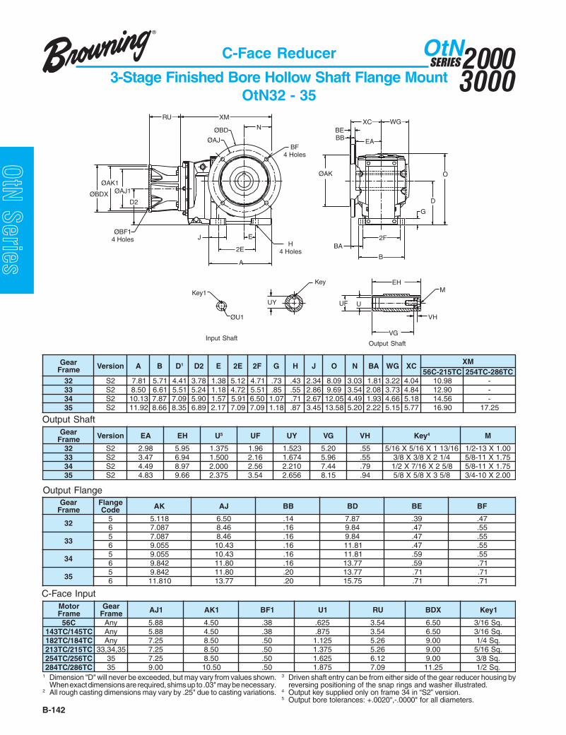
20003000
SERIESOtN
B-142
OtN Series
C-Face Reducer
3-Stage Finished Bore Hollow Shaft Flange MountOtN32 - 35
Output Shaft
C-Face Input
Output Flange
1 Dimension "D" will never be exceeded, but may vary from values shown.When exact dimensions are required, shims up to .03" may be necessary.
2 All rough casting dimensions may vary by .25" due to casting variations.
3 Driven shaft entry can be from either side of the gear reducer housing byreversing positioning of the snap rings and washer illustrated.
4 Output key supplied only on frame 34 in “S2” version.5 Output bore tolerances: +.0020",-.0000" for all diameters.
ØAK
D
O
B
2F
A
2E
J EBA
G
XC
ØAJ
ØBD N
BF4 Holes
ØBF14 Holes
H4 Holes
BEBB
WG
Key1
ØU1
RU XM
D2
ØAK1
ØBDX ØAJ1
UY UUF
M
VG
VH
Key EH
EA
Input ShaftOutput Shaft
raeGemarF noisreV A B D1 2D E E2 F2 G H J O N AB GW CX MX
CT512-C65 CT682-CT45223 2S 18.7 17.5 14.4 87.3 83.1 21.5 17.4 37. 34. 43.2 90.8 30.3 18.1 22.3 40.4 89.01 -33 2S 05.8 16.6 15.5 42.5 81.1 27.4 15.5 58. 55. 68.2 96.9 45.3 80.2 37.3 48.4 09.21 -43 2S 31.01 78.7 90.7 09.5 75.1 19.5 05.6 70.1 17. 76.2 50.21 94.4 39.1 66.4 81.5 65.41 -53 2S 29.11 66.8 53.8 98.6 71.2 90.7 90.7 81.1 78. 54.3 85.31 02.5 22.2 51.5 77.5 09.61 52.71
raeGemarF noisreV AE HE U5 FU YU GV HV yeK 4 M
23 2S 89.2 59.5 573.1 69.1 325.1 02.5 55. 61/311X61/5X61/5 00.1X31-2/133 2S 74.3 49.6 005.1 61.2 476.1 69.5 55. 4/12X8/3X8/3 57.1X11-8/543 2S 94.4 79.8 000.2 65.2 012.2 44.7 97. 8/52X61/7X2/1 57.1X11-8/553 2S 38.4 66.9 573.2 45.3 656.2 51.8 49. 8/53X8/5X8/5 00.2X01-4/3
raeGemarF
egnalFedoC KA JA BB DB EB FB
235 811.5 05.6 41. 78.7 93. 74.6 780.7 64.8 61. 48.9 74. 55.
335 780.7 64.8 61. 48.9 74. 55.6 550.9 34.01 61. 18.11 74. 55.
435 550.9 34.01 61. 18.11 95. 55.6 248.9 08.11 61. 77.31 95. 17.
535 248.9 08.11 02. 77.31 17. 17.6 018.11 77.31 02. 57.51 17. 17.
rotoMemarF
raeGemarF 1JA 1KA 1FB 1U UR XDB 1yeK
C65 ynA 88.5 05.4 83. 526. 45.3 05.6 .qS61/3CT541/CT341 ynA 88.5 05.4 83. 578. 45.3 05.6 .qS61/3CT481/CT281 ynA 52.7 05.8 05. 521.1 62.5 00.9 .qS4/1CT512/CT312 53,43,33 52.7 05.8 05. 573.1 62.5 00.9 .qS61/5CT652/CT452 53 52.7 05.8 05. 526.1 21.6 00.9 .qS8/3CT682/CT482 53 00.9 05.01 05. 578.1 90.7 52.11 .qS2/1

B-143
20003000
SERIESOtN
OtN SeriesC-Face Reducer
3-Stage Finished Bore Hollow Shaft Flange MountOtN26 - 28
1 Dimension "D" will never be exceeded, but may vary from values shown.When exact dimensions are required, shims up to .03" may be necessary.
2 All rough casting dimensions may vary by .25" due to casting variations.
3 Driven shaft entry can be from either side of the gear reducer housing byreversing positioning of the snap rings and washer illustrated.
4 Output bore tolerances: +.0020",-.0000" for all diameters.
raeGemarF noisreV A B D1 2D E E2 F2 G H J O N AB CX GW MX
62 1S 37.61 24.11 68.8 34.8 99.6 89.31 54.9 75.1 78. 45.3 56.61 47.8 45.3 00.9 79.6 51.0272 1S 92.91 06.21 48.9 66.8 72.8 45.61 36.01 77.1 49. 49.3 05.81 40.01 45.3 55.8 27.7 00.3282 1S 32.32 41.61 04.21 24.11 40.01 80.02 87.31 79.1 20.1 33.4 07.32 10.21 47.3 15.11 94.9 50.03
Output Shaft
C-Face Input
Output Flange
raeGemarF noisreV AE HE U4 FU YU GV HV yeK M
62 1S 01.6 02.21 057.2 53.3 720.3 52.01 19. .qS8/5 01-4/372 1S 07.6 04.31 521.3 57.3 454.3 04.11 19. .qS4/3 01-4/382 1S 54.8 09.61 526.3 53.4 900.4 59.41 20.1 .qS8/7 8-1
raeGemarF
egnalFedoC JA KA BB DB EB FB
62 5 57.51 57.31 02. 27.71 97. 17.72 5 57.51 87.31 02. 27.71 97. 17.82 5 96.91 27.71 42. 56.12 49. 17.
D
O
G
2F
B
VH
EH
UUF
VG
M
A
2E
J E
Key
UY
BA
EA
XCXM
N
BF8 Holes
BF14 Holes
H4 Holes
ØBDØAJ
BE
AK
BBWG
AJ1AK1
RU
ØBDX
D2
ØU1
Key1
Input ShaftOutput Shaft
rotoMemarF
raeGemarF 1JA 1KA 1FB 1U UR XDB 1yeK
CT481/CT281 62 52.7 05.8 05. 521.1 79.6 60.9 .qS4/172 52.7 05.8 05. 521.1 59.7 60.9 .qS4/1
CT512/CT31262 52.7 05.8 05. 573.1 79.6 60.9 .qS61/572 52.7 05.8 05. 573.1 59.7 60.9 .qS61/582 52.7 05.8 05. 573.1 86.7 60.9 .qS61/5
CT652/CT45262 52.7 05.8 05. 526.1 21.6 60.9 .qS8/372 52.7 05.8 05. 526.1 59.7 60.9 .qS8/382 52.7 05.8 05. 526.1 86.7 60.9 .qS8/3
CT682/CT48262 00.9 05.01 05. 578.1 90.7 20.11 .qS2/172 00.9 05.01 05. 578.1 66.8 20.11 .qS2/182 00.9 05.01 05. 578.1 93.8 20.11 .qS2/1
CT623/CT423 82 00.11 05.21 36. 521.2 83.9 91.31 .qS2/1

20003000
SERIESOtN
B-144
OtN Series
C-Face Reducer
Combined Finished Bore Hollow Shaft Flange MountOtN32 - 35
Output Shaft
C-Face Input
Output Flange
Input Shaft Output Shaft
A
2E
J
ØBD
ØAJ
EA
WG
BB
OD
G
ØAK
EB2FBA
N
BF4 Holes
H4 Holes
ØBF14 Holes
XC
BE
D2
XM
AK1AJ1
BDX
RU
ØU1
Key1
UY UUF
M
VG
VH
Key EH
raeGemarF noisreV A B D1 2D E E2 F2 G H J O N AB GW CX MX
23 2S 18.7 17.5 14.4 60.4 83.1 21.5 17.4 37. 34. 43.2 90.8 30.3 18.1 22.3 40.4 94.41A33,33 2S 05.8 16.6 15.5 19.4 81.1 27.4 15.5 58. 55. 68.2 96.9 45.3 80.2 37.3 48.4 09.91 3
43 2S 31.01 78.7 90.7 75.5 75.1 19.5 05.6 70.1 17. 76.2 50.21 94.4 39.1 66.4 81.5 55.1253 2S 29.11 66.8 53.8 65.6 71.2 90.7 90.7 81.1 78. 54.3 85.31 02.5 22.2 51.5 77.5 78.32
raeGemarF noisreV AE HE U6 FU YU GV HV yeK 5 M
23 2S 89.2 59.5 573.1 69.1 325.1 02.5 55. 61/311X61/5X61/5 00.1X31-2/1A33,33 2S 74.3 49.6 005.1 61.2 476.1 69.5 55. 4/12X8/3X8/3 57.1X11-8/5
43 2S 94.4 79.8 000.2 65.2 012.2 44.7 97. 8/52X61/7X2/1 57.1X11-8/553 2S 38.4 66.9 573.2 45.3 656.2 51.8 49. 8/53X8/5X8/5 00.2X01-4/3
raeGemarF
egnalFedoC KA JA BB DB EB FB
235 811.5 05.6 41. 78.7 93. 74.6 780.7 64.8 61. 48.9 74. 55.
A33,335 780.7 64.8 61. 48.9 74. 55.6 550.9 34.01 61. 18.11 74. 55.
435 550.9 34.01 61. 18.11 95. 55.6 248.9 08.11 61. 77.31 95. 17.
535 248.9 08.11 02. 77.31 17. 17.6 018.11 77.31 02. 57.51 17. 17.
rotoMemarF
raeGemarF 1JA 1KA 1FB 1U UR XDB 1yeK
C65A33,23 88.5 05.4 83. 526. 33.3 05.6 .qS61/353,43,33 88.5 05.4 83. 526. 45.3 05.6 .qS61/3
CT541/CT341A33,23 88.5 05.4 83. 578. 33.3 05.6 .qS61/353,43,33 88.5 05.4 83. 578. 45.3 05.6 .qS61/3
CT481/CT281 53,43,33 52.7 05.8 05. 521.1 62.5 00.9 .qS4/11 Dimension "D" will never be exceeded, but may vary from values shown.
When exact dimensions are required, shims up to .03" may be necessary.2 All rough casting dimensions may vary by .25" due to casting variations.3 XM dimension when gear frame 33A is used will be 16.42.
4 Driven shaft entry can be from either side of the gear reducer housing byreversing positioning of the snap rings and washer illustrated.
5 Output key supplied only on frame 34 in “S2” version.6 Output bore tolerances: +.0020",-.0000" for all diameters.
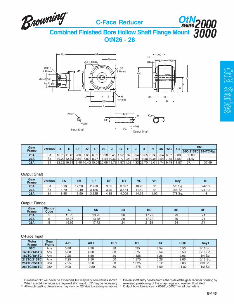
B-145
20003000
SERIESOtN
OtN SeriesC-Face Reducer
Combined Finished Bore Hollow Shaft Flange MountOtN26 - 28
1 Dimension "D" will never be exceeded, but may vary from values shown.When exact dimensions are required, shims up to .03" may be necessary.
2 All rough casting dimensions may vary by .25" due to casting variations.
3 Driven shaft entry can be from either side of the gear reducer housing byreversing positioning of the snap rings and washer illustrated.
4 Output bore tolerances: +.0020",-.0000" for all diameters.
Output Shaft
C-Face Input
Output Flange
Input ShaftOutput Shaft
UY
AK
J
UF
D2
U
VG
M
VH
E
2E
A
EHKey
ØAJ
XMRU
NØBD
BF8 Holes
H4 Holes
ØBF14 Holes
D
O
B
2FBA
G
XC
EABE
BBWG
AJ1
AK1
ØBDX
ØU1
Key1
raeGemarF noisreV A B D1 2D E E2 F2 G H J O N AB GW CX MX
CT512-C65 pU-CT452A62 1S 37.61 24.11 68.8 66.7 99.6 89.31 54.9 75.1 78. 45.3 56.61 47.8 45.3 79.6 00.9 08.03 -A72 1S 92.91 06.21 48.9 98.7 72.8 45.61 36.01 77.1 49. 49.3 05.81 40.01 45.3 27.7 55.8 74.13 -A82 1S 32.32 41.61 04.21 04.01 40.01 80.02 87.31 79.1 20.1 33.4 07.32 10.21 47.3 94.9 75.11 41.73 94.73
raeGemarF noisreV AE HE U4 FU YU GV HV yeK M
A62 1S 01.6 02.21 057.2 53.3 720.3 52.01 19. .qS8/5 01-4/3A72 1S 07.6 04.31 521.3 57.3 454.3 04.11 19. qS4/3 01-4/3A82 1S 54.8 09.61 526.3 53.4 900.4 59.41 20.1 .qS8/7 8-1
raeGemarF
egnalFedoC JA KA BB DB EB FB
A62 5 57.51 57.31 02. 27.71 97. 17.A72 5 57.51 87.31 02. 27.71 97. 17.A82 5 96.91 27.71 42. 56.12 49. 17.
rotoMemarF
raeGemarF 1JA 1KA 1FB 1U UR XDB 1yeK
C65 ynA 88.5 05.4 83. 526. 45.3 05.6 .qS61/3CT541/CT341 ynA 88.5 05.4 83. 578. 45.3 05.6 .qS61/3CT481/CT281 ynA 52.7 05.8 05. 521.1 62.5 60.9 .qS4/1CT512/CT312 ynA 52.7 05.8 05. 573.1 62.5 60.9 .qS61/5CT652/CT452 A82 52.7 05.8 05. 526.1 21.6 60.9 .qS8/3CT682/CT482 A82 00.9 05.01 05. 578.1 90.7 20.11 .qS2/1
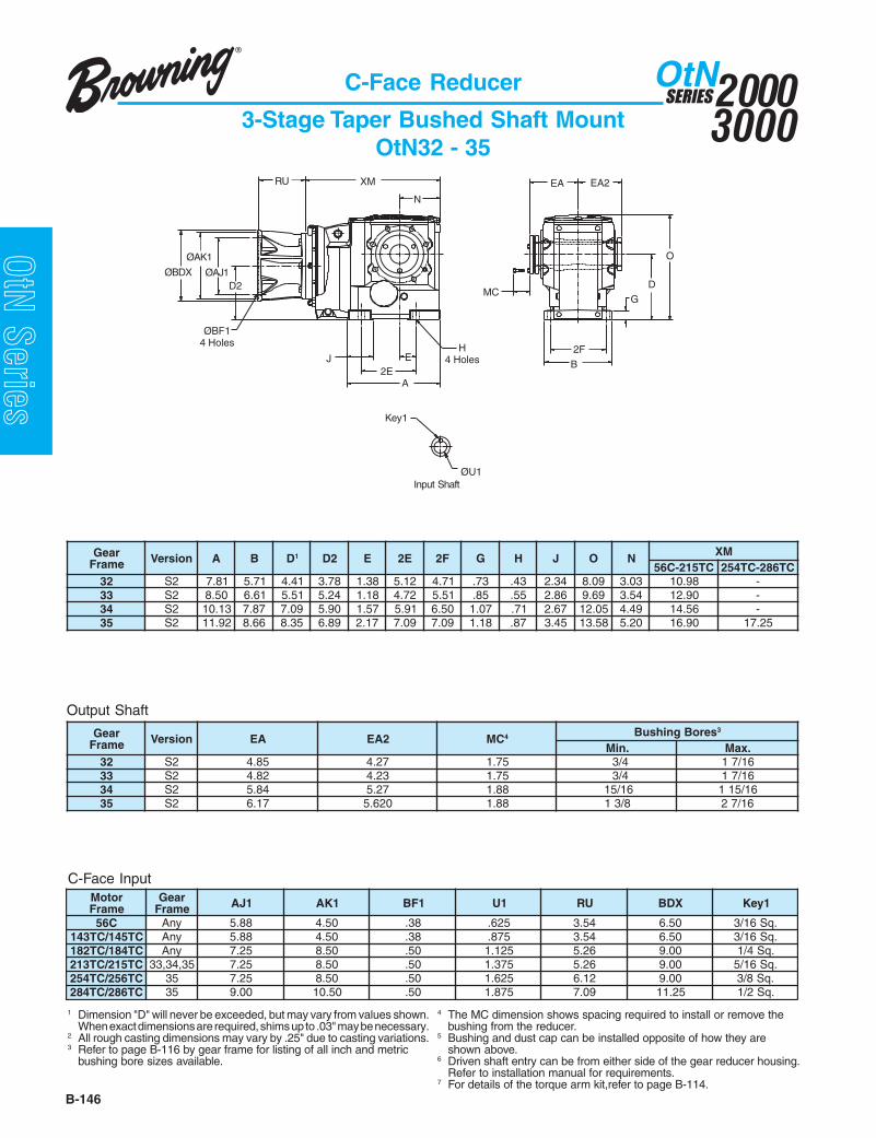
20003000
SERIESOtN
B-146
OtN Series
C-Face Reducer
3-Stage Taper Bushed Shaft MountOtN32 - 35
Output Shaft
C-Face Input
raeGemarF noisreV A B D1 2D E E2 F2 G H J O N MX
CT512-C65 CT682-CT45223 2S 18.7 17.5 14.4 87.3 83.1 21.5 17.4 37. 34. 43.2 90.8 30.3 89.01 -33 2S 05.8 16.6 15.5 42.5 81.1 27.4 15.5 58. 55. 68.2 96.9 45.3 09.21 -43 2S 31.01 78.7 90.7 09.5 75.1 19.5 05.6 70.1 17. 76.2 50.21 94.4 65.41 -53 2S 29.11 66.8 53.8 98.6 71.2 90.7 90.7 81.1 78. 54.3 85.31 02.5 09.61 52.71
raeGemarF noisreV AE 2AE CM 4 seroBgnihsuB 3
.niM .xaM23 2S 58.4 72.4 57.1 4/3 61/7133 2S 28.4 32.4 57.1 4/3 61/7143 2S 48.5 72.5 88.1 61/51 61/51153 2S 71.6 026.5 88.1 8/31 61/72
rotoMemarF
raeGemarF 1JA 1KA 1FB 1U UR XDB 1yeK
C65 ynA 88.5 05.4 83. 526. 45.3 05.6 .qS61/3CT541/CT341 ynA 88.5 05.4 83. 578. 45.3 05.6 .qS61/3CT481/CT281 ynA 52.7 05.8 05. 521.1 62.5 00.9 .qS4/1CT512/CT312 53,43,33 52.7 05.8 05. 573.1 62.5 00.9 .qS61/5CT652/CT452 53 52.7 05.8 05. 526.1 21.6 00.9 .qS8/3CT682/CT482 53 00.9 05.01 05. 578.1 90.7 52.11 .qS2/1
1 Dimension "D" will never be exceeded, but may vary from values shown.When exact dimensions are required, shims up to .03" may be necessary.
2 All rough casting dimensions may vary by .25" due to casting variations.3 Refer to page B-116 by gear frame for listing of all inch and metric
bushing bore sizes available.
4 The MC dimension shows spacing required to install or remove thebushing from the reducer.
5 Bushing and dust cap can be installed opposite of how they areshown above.
6 Driven shaft entry can be from either side of the gear reducer housing.Refer to installation manual for requirements.
7 For details of the torque arm kit,refer to page B-114.
D
O
B
2F
A2E
J E
G
N
Key1
ØU1
XMRU
ØAJ1ØBDX
ØAK1
D2
EA2EA
MC
Input Shaft
ØBF14 Holes H
4 Holes

B-147
20003000
SERIESOtN
OtN SeriesC-Face Reducer
Combined Taper Bushed Shaft MountOtN32 - 35
Output Shaft
C-Face Input
raeGemarF noisreV A B D1 2D E E2 F2 G H J O N MX
23 2S 18.7 17.5 14.4 60.4 83.1 21.5 27.4 37. 34. 43.2 90.8 30.3 94.41A33,33 2S 05.8 16.6 15.5 19.4 81.1 27.4 15.5 58. 55. 68.2 96.9 45.3 09.91 8
43 2S 31.01 78.7 90.7 75.5 75.1 19.5 05.6 70.1 17. 76.2 50.21 94.4 55.1253 2S 29.11 66.8 53.8 65.6 71.2 90.7 90.7 81.1 78. 54.3 85.31 02.5 78.32
raeGemarF noisreV AE 2AE CM 4 seroBgnihsuB 3
.niM .xaM23 2S 58.4 72.4 57.1 4/3 61/71
A33,33 2S 28.4 32.4 57.1 4/3 61/7143 2S 48.5 72.5 88.1 61/51 61/51153 2S 71.6 026.5 88.1 8/31 61/72
rotoMemarF
raeGemarF 1JA 1KA 1FB 1U UR XDB 1yeK
C65A33,23 88.5 05.4 83. 526. 33.3 05.6 .qS61/353,43,33 88.5 05.4 83. 526. 45.3 05.6 .qS61/3
CT541/CT341A33,23 88.5 05.4 83. 578. 33.3 05.6 .qS61/353,43,33 88.5 05.4 83. 578. 45.3 05.6 .qS61/3
CT481/CT281 53,43,33 52.7 05.8 05. 521.1 62.5 00.9 .qS4/1
1 Dimension "D" will never be exceeded, but may vary from values shown.When exact dimensions are required, shims up to .03" may be necessary.
2 All rough casting dimensions may vary by .25" due to casting variations.3 Refer to page B-116 by gear frame for listing of all inch and metric
bushing bore sizes available.4 The MC dimension shows spacing required to install or remove the
bushing from the reducer.
5 Bushing and dust cap can be installed opposite of how they areshown above.
6 Driven shaft entry can be from either side of the gear reducer housing.Refer to installation manual for requirements.
7 For details of the torque arm kit,refer to page B-114.8 XM dimension when gear frame 33A is used will be 16.42.
GD
O
EA2EAN
J
A2E
Input Shaft
ØBF14 Holes
H4 Holes
MC
EB2F
D2
XM
AK1AJ1
BDX
RU
ØU1
Key1

20003000
SERIESOtN
B-148
OtN Series
RU
D2
Key1
Input Shaft
D
O
B2F
MTap
Key
Output Shaft
UY
VES
A
H4 HolesJ E
2E
G
EA
N
XM
U
EA
U1
UY1
V1
AH
Input Shaft Reducer
3-Stage Output Shafted Foot MountOtN32 - 35 and OtN26 - 28
Output Shaft
Input Shaft
raeGemarF noisreV A B D1 2D E E2 F2 G H J O N MX
23 2S 18.7 17.5 14.4 87.3 83.1 21.5 27.4 37. 34. 43.2 90.8 30.3 40.01
332S 05.8 16.6 15.5 42.5 81.1 27.4 15.5 58. 55. 68.2 96.9 45.3 79.111S 80.8 85.8 29.4 02.5 53.3 96.6 01.6 97. 55. 72.2 34.01 45.3 79.11
432S 31.01 78.7 90.7 09.5 75.1 19.5 05.6 70.1 17. 76.2 50.21 94.4 87.311S 96.01 06.9 03.6 94.7 35.4 60.9 86.7 81.1 17. 91.3 93.31 94.4 87.31
532S 29.11 66.8 53.8 98.6 71.2 90.7 90.7 81.1 78. 73.3 85.31 02.5 59.511S 70.31 89.01 78.7 33.9 15.5 20.11 60.9 04.1 78. 50.4 22.61 02.5 59.51
62 1S 37.61 24.11 68.8 34.8 99.6 89.31 54.9 75.1 78. 45.3 56.61 47.8 51.0272 1S 92.91 06.21 48.9 66.8 72.8 45.61 36.01 77.1 49. 49.3 05.81 40.01 42.2282 1S 32.32 41.61 04.21 24.11 40.01 80.02 87.31 79.1 20.1 33.4 07.32 10.21 61.72
raeGemarF noisreV U3 YU V HA AE yeK SE M
23 2S 052.1 453.1 63.2 64.2 13.5 .qS4/1 60.2 21.1X31-2/1
332S 526.1 387.1 52.3 93.3 37.6 .qS8/3 87.2 83.1X11-8/51S 005.1 756.1 81.3 91.3 21.7 .qS8/3 87.2 83.1X11-8/5
432S 000.2 012.2 36.3 67.3 11.8 .qS2/1 60.3 16.1X01-4/31S 057.1 909.1 65.3 66.3 64.8 .qS8/3 65.3 16.1X01-4/3
532S 573.2 836.2 16.4 47.4 54.9 .qS8/5 18.3 16.1X01-4/31S 573.2 836.2 37.5 72.5 75.01 .qS8/5 18.4 16.1X01-4/3
62 1S 578.2 002.3 57.5 19.5 28.21 .qS4/3 31.5 79.1X01-4/372 1S 005.3 288.3 10.7 33.7 07.31 .qS8/7 52.6 79.1X8-182 1S 578.3 624.4 99.7 91.8 60.71 .qS00.1 52.7 79.1X8-1
raeGemarF noisreV UR 1U 4 1YU 1V 1yeK
23 2S 71.3 526. 507. 52.1 .qS61/333 2S,1S 71.3 526. 507. 52.1 .qS61/343 2S,1S 57.4 521.1 632.1 52.2 .qS4/153 2S,1S 30.5 521.1 632.1 52.2 .qS4/162 1S 94.6 573.1 315.1 57.2 .qS61/572 1S 67.5 578.1 190.2 57.3 .qS2/182 1S 11.7 573.2 646.2 57.4 .qS8/5
1 Dimension "D" will never be exceeded, but may vary from values shown.When exact dimensions are required, shims up to .03" may be necessary.
2 All rough casting dimensions may vary by .25" due to casting variations.
3 Output shaft extension tolerances: +.0000"; –.0005" for shafts up to 1.5"diameter "U". Larger diameter "U", +.000"; –.001".
4 Input shaft extension tolerances: +.0000"; –.0005" up to 1.5" diameter.Larger diameter "U1", +.000"; –.001".

B-149
20003000
SERIESOtN
OtN Series
2F
EA
B
D2
U1
RU
A
XM
2E
JH
4 Holes
E
D
O
G
N
U
EA
ESV
V1
UY1 UY
MTap
Key1 Key
AH
V1
FWFlat
Input ShaftFrame 32 and 33A Only Frames 33 and 34 - 28A
Input Shaft
Output Shaft
FL
1 Dimension "D" will never be exceeded, but may vary from values shown.When exact dimensions are required, shims up to .03" may be necessary.
2 All rough casting dimensions may vary by .25" due to casting variations.3 Output shaft extension tolerances: +.0000"; –.0005" for shafts up to 1.5"
diameter "U". Larger diameter "U", +.000"; –.001".
4 XM dimension when gear frame 33A is used will be 16.42.5 Input shaft extension tolerances: +.0000"; –.0005" up to 1.5" diameter.
Larger diameter "U1", +.000"; –.001".
Input Shaft Reducer
Combined Output Shafted Foot MountOtN32 - 35 and OtN26 - 28
raeGemarF noisreV A B D1 2D E E2 F2 G H J O N MX
23 2S 18.7 17.5 14.4 60.4 83.1 21.5 27.4 37. 34. 43.2 90.8 30.3 94.41
A33,332S 05.8 16.6 15.5 19.4 81.1 27.4 15.5 58. 55. 68.2 96.9 45.3 09.91 4
1S 80.8 85.8 29.4 78.4 53.3 96.6 01.6 97. 55. 72.2 34.01 45.3 09.91 4
432S 31.01 78.7 90.7 75.5 75.1 19.5 05.6 70.1 17. 76.2 50.21 94.4 55.121S 96.01 06.9 03.6 61.7 35.4 60.9 86.7 81.1 17. 91.3 93.31 94.4 55.12
532S 29.11 66.8 53.8 65.6 71.2 90.7 90.7 81.1 78. 73.3 85.31 02.5 78.321S 70.31 89.01 78.7 00.9 15.5 20.11 60.9 04.1 78. 50.4 22.61 02.5 78.32
A62 1S 37.61 24.11 68.8 66.7 99.6 89.31 54.9 75.1 78. 45.3 56.61 47.8 08.03A72 1S 92.91 06.21 48.9 98.7 72.8 45.61 36.01 77.1 49. 49.3 05.81 40.01 74.13A82 1S 32.32 41.61 04.21 04.01 40.01 80.02 87.31 79.1 20.1 33.4 07.32 10.21 94.73
raeGemarF noisreV U3 YU V HA AE yeK SE M
23 2S 052.1 453.1 63.2 64.2 13.5 .qS4/1 60.2 21.1X31-2/1
A33,332S 526.1 387.1 52.3 93.3 37.6 .qS8/3 87.2 83.1X11-8/51S 005.1 756.1 81.3 91.3 21.7 .qS8/3 87.2 83.1X11-8/5
432S 000.2 012.2 36.3 67.3 11.8 .qS2/1 60.3 16.1X01-4/31S 057.1 909.1 65.3 66.3 64.8 .qS8/3 65.3 16.1X01-4/3
532S 573.2 836.2 16.4 47.4 54.9 .qS8/5 18.3 16.1X01-4/31S 573.2 836.2 37.5 72.5 75.01 .qS8/5 18.4 16.1X01-4/3
A62 1S 578.2 002.3 57.5 19.5 28.21 .qS4/3 31.5 79.1X01-4/3A72 1S 005.3 288.3 10.7 33.7 07.31 .qS8/7 52.6 79.1X8-1A82 1S 578.3 624.4 99.7 91.8 60.71 .qS00.1 52.7 79.1X8-1
raeGemarF noisreV UR 1U 5 LF WF 1YU 1V 1yeK
A33,23 2S 06.3 005. 68. 64. - 00.1 -33 2S,1S 71.3 526. - - 507. 52.1 .qS61/343 2S,1S 71.3 526. - - 507. 52.1 .qS61/353 2S,1S 71.3 526. - - 507. 52.1 .qS61/3A62 1S 57.4 521.1 - - 632.1 52.2 .qS4/1A72 1S 57.4 521.1 - - 632.1 52.2 .qS4/1A82 1S 30.5 521.1 - - 632.1 52.2 .qS4/1
Output Shaft
Input Shaft
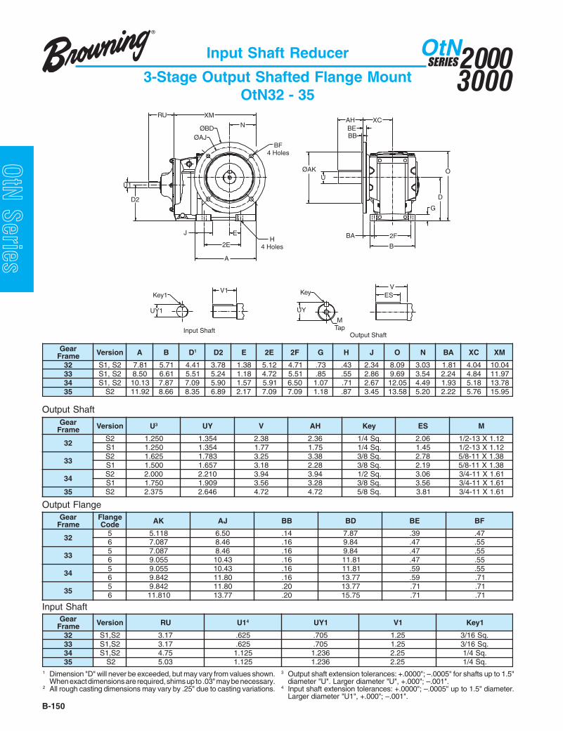
20003000
SERIESOtN
B-150
OtN Series
Input Shaft Reducer
3-Stage Output Shafted Flange MountOtN32 - 35
raeGemarF noisreV A B D1 2D E E2 F2 G H J O N AB CX MX
23 2S,1S 18.7 17.5 14.4 87.3 83.1 21.5 17.4 37. 34. 43.2 90.8 30.3 18.1 40.4 40.0133 2S,1S 05.8 16.6 15.5 42.5 81.1 27.4 15.5 58. 55. 68.2 96.9 45.3 42.2 48.4 79.1143 2S,1S 31.01 78.7 90.7 09.5 75.1 19.5 05.6 70.1 17. 76.2 50.21 94.4 39.1 81.5 87.3153 2S 29.11 66.8 53.8 98.6 71.2 90.7 90.7 81.1 78. 54.3 85.31 02.5 22.2 67.5 59.51
raeGemarF noisreV U3 YU V HA yeK SE M
232S 052.1 453.1 83.2 63.2 .qS4/1 60.2 21.1X31-2/11S 052.1 453.1 77.1 57.1 .qS4/1 54.1 21.1X31-2/1
332S 526.1 387.1 52.3 83.3 .qS8/3 87.2 83.1X11-8/51S 005.1 756.1 81.3 82.2 .qS8/3 91.2 83.1X11-8/5
432S 000.2 012.2 49.3 49.3 .qS2/1 60.3 16.1X11-4/31S 057.1 909.1 65.3 82.3 .qS8/3 65.3 16.1X11-4/3
53 2S 573.2 646.2 27.4 27.4 .qS8/5 18.3 16.1X11-4/3
Output Shaft
Input Shaft
raeGemarF
egnalFedoC KA JA BB DB EB FB
235 811.5 05.6 41. 78.7 93. 74.6 780.7 64.8 61. 48.9 74. 55.
335 780.7 64.8 61. 48.9 74. 55.6 550.9 34.01 61. 18.11 74. 55.
435 550.9 34.01 61. 18.11 95. 55.6 248.9 08.11 61. 77.31 95. 17.
535 248.9 08.11 02. 77.31 17. 17.6 018.11 77.31 02. 57.51 17. 17.
raeGemarF noisreV UR 1U 4 1YU 1V 1yeK
23 2S,1S 71.3 526. 507. 52.1 .qS61/333 2S,1S 71.3 526. 507. 52.1 .qS61/343 2S,1S 57.4 521.1 632.1 52.2 .qS4/153 2S 30.5 521.1 632.1 52.2 .qS4/1
1 Dimension "D" will never be exceeded, but may vary from values shown.When exact dimensions are required, shims up to .03" may be necessary.
2 All rough casting dimensions may vary by .25" due to casting variations.
3 Output shaft extension tolerances: +.0000"; –.0005" for shafts up to 1.5"diameter "U". Larger diameter "U", +.000"; –.001".
4 Input shaft extension tolerances: +.0000"; –.0005" up to 1.5" diameter.Larger diameter "U1", +.000"; –.001".
Output Flange
RU
D2
BA
G
O
D
A
2E
J E
B
2F
ØAK
N
BF4 Holes
H4 Holes
XM
ØAJ
U
ØBDXC
BEBB
ESVV1
UY1 UY
MTap
Output Shaft
Key1
Input Shaft
Key
AH
U1

B-151
20003000
SERIESOtN
OtN SeriesInput Shaft Reducer
3-Stage Output Shafted Flange MountOtN26 - 28
Output Shaft
Input Shaft
1 Dimension "D" will never be exceeded, but may vary from values shown.When exact dimensions are required, shims up to .03" may be necessary.
2 All rough casting dimensions may vary by .25" due to casting variations.
3 Output shaft extension tolerances: +.0000"; –.0005" for shafts up to 1.5"diameter "U". Larger diameter "U", +.000"; –.001".
4 Input shaft extension tolerances: +.0000"; –.0005" up to 1.5" diameter.Larger diameter "U1", +.000"; –.001".
Output Flange
Key1
O
XCXMRU
A
UYM
Tap
ESV
Key
ØAJ
J
D2
E H4 Holes
BF8 Holes
2E
N
ØBD BB
BA
BE
AK
U
D
2F
B
G
UY1
Input Shaft Output Shaft
V1
XH
raeGemarF noisreV A B D1 2D E E2 F2 G H J O N AB CX MX
62 1S 37.61 24.11 68.8 34.8 99.6 89.31 54.9 75.1 78. 45.3 56.61 47.8 45.3 00.9 51.0272 1S 92.91 06.21 48.9 66.8 72.8 45.61 36.01 77.1 49. 49.3 05.81 40.01 45.3 55.8 42.2282 1S 32.32 41.61 04.21 24.11 40.01 80.02 87.31 79.1 20.1 33.4 07.32 10.21 47.3 15.11 61.72
raeGemarF noisreV U3 YU V HA yeK SE M
62 1S 578.2 002.3 57.5 57.5 .qS4/3 31.5 79.1X01-4/372 1S 005.3 288.3 00.7 00.7 .qS8/7 52.6 79.1X8-182 1S 000.4 634.4 00.8 00.8 .qS00.1 52.7 79.1X8-1
raeGemarF
egnalFedoC JA KA BB DB EB FB
62 5 57.51 57.31 02. 27.71 97. 17.72 5 57.51 87.31 02. 27.71 97. 17.82 5 96.91 27.71 42. 56.12 49. 17.
raeGemarF noisreV UR 1U 4 1YU 1V 1yeK
62 1S 94.6 573.1 315.1 57.2 .qS61/572 1S 67.5 578.1 190.2 57.3 .qS2/182 1S 11.7 573.2 646.2 57.4 .qS8/5

20003000
SERIESOtN
B-152
OtN Series
BB
O
D
E
A
J
BF4 Holes
H4 Holes2E
ØAKU
BA
B
2F
G
NØBD
ØAJ
XC
BE
XM
U1
D2
RU
ESVV1
UYUY1M
Tap
KeyKey1
Input ShaftFrame 32 and 33A Only
Input ShaftFrames 33, 34 and 35 Output Shaft
AH
V1
FWFlat
FL
Input Shaft Reducer
Combined Output Shafted Flange MountOtN32 - 35
Output Shaft
Input Shaft
Output Flange
raeGemarF noisreV A B D1 2D E E2 F2 G H J O N AB CX MX
23 2S,1S 18.7 17.5 14.4 60.4 83.1 21.5 17.4 37. 34. 43.2 90.8 30.3 18.1 40.4 94.41A33,33 2S,1S 05.8 16.6 15.5 19.4 81.1 27.4 15.5 58. 55. 68.2 96.9 45.3 42.2 48.4 09.91 4
43 2S,1S 31.01 78.7 90.7 75.5 75.1 19.5 05.6 70.1 17. 76.2 50.21 94.4 39.1 81.5 55.1253 2S 29.11 66.8 53.8 65.6 71.2 90.7 90.7 81.1 78. 54.3 85.31 02.5 22.2 67.5 78.32
raeGemarF noisreV U3 YU V HA yeK SE M
232S 052.1 453.1 83.2 63.2 .qS4/1 60.2 21.1X31-2/11S 052.1 453.1 77.1 57.1 .qS4/1 54.1 21.1X31-2/1
A33,332S 526.1 387.1 52.3 83.3 .qS8/3 87.2 83.1X11-8/51S 005.1 756.1 81.3 82.2 .qS8/3 91.2 83.1X11-8/5
432S 000.2 012.2 49.3 49.3 .qS2/1 60.3 16.1X01-4/31S 057.1 909.1 65.3 82.3 .qS8/3 65.3 16.1X01-4/3
53 2S 573.2 836.2 27.4 27.4 .qS8/5 18.3 16.1X01-4/3
raeGemarF
egnalFedoC KA JA BB DB EB FB
235 811.5 05.6 41. 78.7 93. 74.6 780.7 64.8 61. 48.9 74. 55.
A33,335 780.7 64.8 61. 48.9 74. 55.6 550.9 34.01 61. 18.11 74. 55.
435 550.9 34.01 61. 18.11 95. 55.6 248.9 08.11 61. 77.31 95. 17.
535 248.9 08.11 02. 77.31 17. 17.6 018.11 77.31 02. 57.51 17. 17.
raeGemarF noisreV UR 1U 5 LF WF 1YU 1V 1yeK
A33,23 2S,1S 06.3 005. 68. 64. - 00.1 -33 2S,1S 71.3 526. - - 507. 52.1 .qS61/343 2S,1S 71.3 526. - - 507. 52.1 .qS61/353 2S 71.3 526. - - 507. 52.1 .qS61/3
1 Dimension "D" will never be exceeded, but may vary from values shown.When exact dimensions are required, shims up to .03" may be necessary.
2 All rough casting dimensions may vary by .25" due to casting variations.3 Output shaft extension tolerances: +.0000"; –.0005" for shafts up to 1.5"
diameter "U". Larger diameter "U", +.000"; –.001".
4 XM dimension when gear frame 33A is used will be 16.42.5 Input shaft extension tolerances: +.0000"; –.0005" up to 1.5" diameter.
Larger diameter "U1", +.000"; –.001".

B-153
20003000
SERIESOtN
OtN SeriesInput Shaft Reducer
Combined Output Shafted Flange MountOtN26 - 28
Output Shaft
Input Shaft
1 Dimension "D" will never be exceeded, but may vary from values shown.When exact dimensions are required, shims up to .03" may be necessary.
2 All rough casting dimensions may vary by .25" due to casting variations.
3 Output shaft extension tolerances: +.0000"; –.0005" for shafts up to 1.5"diameter "U". Larger diameter "U", +.000"; –.001".
4 Input shaft extension tolerances: +.0000"; –.0005" up to 1.5" diameter.Larger diameter "U1", +.000"; –.001".
Output Flange
raeGemarF noisreV A B D1 2D E E2 F2 G H J O N AB CX MX
A62 1S 37.61 24.11 68.8 66.7 99.6 89.31 54.9 75.1 78. 45.3 56.61 47.8 45.3 00.9 08.03A72 1S 92.91 06.21 48.9 98.7 72.8 45.61 36.01 77.1 49. 49.3 05.81 40.01 45.3 55.8 74.13A82 1S 32.32 41.61 04.21 04.01 40.01 80.02 87.31 79.1 20.1 33.4 07.32 10.21 47.3 15.11 94.73
raeGemarF noisreV U3 YU V HA yeK SE M
A62 1S 578.2 002.3 57.5 57.5 .qS4/3 31.5 79.1X01-4/3A72 1S 005.3 288.3 00.7 00.7 .qS8/7 52.6 79.1X8-1A82 1S 000.4 634.4 00.8 00.8 .qS00.1 52.7 79.1X8-1
raeGemarF
egnalFedoC JA KA BB DB EB FB
A62 5 57.51 57.31 02. 27.71 97. 17.A72 5 57.51 87.31 02. 27.71 97. 17.A82 5 96.91 27.71 42. 56.12 49. 17.
raeGemarF noisreV UR 1U 4 1YU 1V 1yeK
A62 1S 57.4 521.1 632.1 52.2 .qS4/1A72 1S 57.4 521.1 632.1 52.2 .qS4/1A82 1S 30.5 521.1 632.1 52.2 .qS4/1
ESVV1
Input Shaft Output Shaft
UYUY1M
Tap
KeyKey1
XM
E
A
2E
N
BF8 Holes
H4 Holes
D2
J
ØAJ ØBD
XC
G
D
O
AK
U
BA
B
2F
BBBE
U1
RUAH
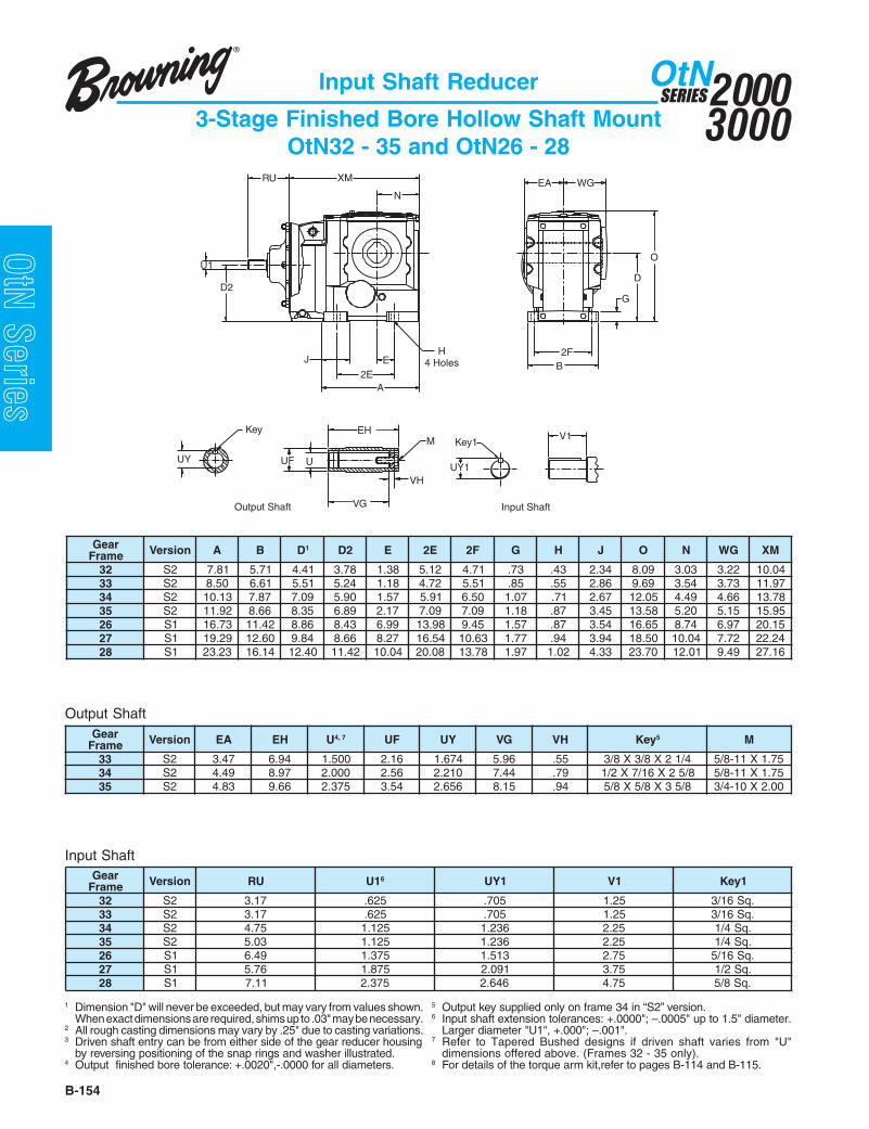
20003000
SERIESOtN
B-154
OtN Series
Input Shaft Reducer
3-Stage Finished Bore Hollow Shaft MountOtN32 - 35 and OtN26 - 28
Output Shaft
Input Shaft
RU
D2
Output Shaft Input Shaft
EA
2FB
A
EH
4 Holes2E
J
N
XM
D
O
G
WG
U1
UY1
Key1V1
UY UUF
M
VG
VH
Key EH
raeGemarF noisreV A B D1 2D E E2 F2 G H J O N GW MX
23 2S 18.7 17.5 14.4 87.3 83.1 21.5 17.4 37. 34. 43.2 90.8 30.3 22.3 40.0133 2S 05.8 16.6 15.5 42.5 81.1 27.4 15.5 58. 55. 68.2 96.9 45.3 37.3 79.1143 2S 31.01 78.7 90.7 09.5 75.1 19.5 05.6 70.1 17. 76.2 50.21 94.4 66.4 87.3153 2S 29.11 66.8 53.8 98.6 71.2 90.7 90.7 81.1 78. 54.3 85.31 02.5 51.5 59.5162 1S 37.61 24.11 68.8 34.8 99.6 89.31 54.9 75.1 78. 45.3 56.61 47.8 79.6 51.0272 1S 92.91 06.21 48.9 66.8 72.8 45.61 36.01 77.1 49. 49.3 05.81 40.01 27.7 42.2282 1S 32.32 41.61 04.21 24.11 40.01 80.02 87.31 79.1 20.1 33.4 07.32 10.21 94.9 61.72
raeGemarF noisreV AE HE U 7,4 FU YU GV HV yeK 5 M
33 2S 74.3 49.6 005.1 61.2 476.1 69.5 55. 4/12X8/3X8/3 57.1X11-8/543 2S 94.4 79.8 000.2 65.2 012.2 44.7 97. 8/52X61/7X2/1 57.1X11-8/553 2S 38.4 66.9 573.2 45.3 656.2 51.8 49. 8/53X8/5X8/5 00.2X01-4/3
raeGemarF noisreV UR 1U 6 1YU 1V 1yeK
23 2S 71.3 526. 507. 52.1 .qS61/333 2S 71.3 526. 507. 52.1 .qS61/343 2S 57.4 521.1 632.1 52.2 .qS4/153 2S 30.5 521.1 632.1 52.2 .qS4/162 1S 94.6 573.1 315.1 57.2 .qS61/572 1S 67.5 578.1 190.2 57.3 .qS2/182 1S 11.7 573.2 646.2 57.4 .qS8/5
1 Dimension "D" will never be exceeded, but may vary from values shown.When exact dimensions are required, shims up to .03" may be necessary.
2 All rough casting dimensions may vary by .25" due to casting variations.3 Driven shaft entry can be from either side of the gear reducer housing
by reversing positioning of the snap rings and washer illustrated.4 Output finished bore tolerance: +.0020",-.0000 for all diameters.
5 Output key supplied only on frame 34 in “S2” version.6 Input shaft extension tolerances: +.0000"; –.0005" up to 1.5" diameter.
Larger diameter "U1", +.000"; –.001".7 Refer to Tapered Bushed designs if driven shaft varies from "U"
dimensions offered above. (Frames 32 - 35 only).8 For details of the torque arm kit,refer to pages B-114 and B-115.

B-155
20003000
SERIESOtN
OtN Series
Output ShaftInput Shaft
Frames 33 and 34-28A
Input ShaftFrame 32 and 33A Only
EA
2FB
A
H4 HolesE
2E
J
N
XM
D
O
G
WG
UY1
Key1V1
RU
U1
D2
V1
FWFlat
FL
UY UUF
M
VG
VH
Key EH
Input Shaft Reducer
Combined Finished Bore Hollow ShaftOtN32 - 35 and OtN26 - 28
raeGemarF noisreV A B D1 2D E E2 F2 G H J O N GW MX
23 2S 18.7 17.5 14.4 60.4 83.1 21.5 17.4 37. 34. 43.2 90.8 30.3 22.3 94.41A33,33 2S 05.8 16.6 15.5 19.4 81.1 27.4 15.5 58. 55. 68.2 96.9 45.3 37.3 09.91 7
43 2S 31.01 78.7 90.7 75.5 75.1 19.5 05.6 70.1 17. 76.2 50.21 94.4 66.4 55.1253 2S 29.11 66.8 53.8 65.6 71.2 90.7 90.7 81.1 78. 54.3 85.31 02.5 51.5 78.32A62 1S 37.61 24.11 68.8 66.7 99.6 89.31 54.9 75.1 78. 45.3 56.61 47.8 79.6 08.03A72 1S 92.91 06.21 48.9 98.7 72.8 45.61 36.01 77.1 49. 49.3 05.81 40.01 27.7 74.13A82 1S 32.32 41.61 04.21 04.01 40.01 80.02 87.31 79.1 20.1 33.4 07.32 10.21 94.9 94.73
raeGemarF noisreV AE HE U 8,4 FU YU GV HV yeK 5 M
23 2S 89.2 59.5 573.1 69.1 325.1 02.5 55. 61/311X61/5X61/5 00.1X31-2/1A33,33 2S 74.3 49.6 005.1 61.2 476.1 69.5 55. 4/12X8/3X8/3 57.1X11-8/5
43 2S 94.4 79.8 000.2 65.2 012.2 44.7 97. 8/52X61/7X2/1 57.1X11-8/553 2S 38.4 66.9 573.2 45.3 656.2 51.8 49. 8/53X8/5X8/5 00.2X01-4/3A62 1S 01.6 02.21 057.2 53.3 720.3 52.01 19. .qS8/5 01-4/3A72 1S 07.6 04.31 521.3 57.3 454.3 04.11 19. .qS4/3 01-4/3A82 1S 54.8 09.61 526.3 53.4 900.4 59.41 20.1 .qS8/7 8-1
raeGemarF noisreV UR 1U 6 LF WF 1YU 1V 1yeK
A33,23 2S 06.3 005. 68. 64. - 00.1 -33 2S 71.3 526. - - 507. 52.1 .qS61/343 2S 71.3 526. - - 507. 52.1 .qS61/353 2S 71.3 526. - - 507. 52.1 .qS61/3A62 1S 57.4 521.1 - - 632.1 52.2 .qS4/1A72 1S 57.4 521.1 - - 632.1 52.2 .qS4/1A82 1S 30.5 521.1 - - 632.1 52.2 .qS4/1
Output Shaft
Input Shaft
1 Dimension "D" will never be exceeded, but may vary from values shown.When exact dimensions are required, shims up to .03" may be necessary.
2 All rough casting dimensions may vary by .25" due to casting variations.3 Driven shaft entry can be from either side of the gear reducer housing
by reversing positioning of the snap rings and washer illustrated.4 Output finished bore tolerance: +.0020",-.0000 for all diameters.
5 Output key supplied only on frame 34 in “S2” version.6 Input shaft extension tolerances: +.0000"; –.0005" up to 1.5" diameter.
Larger diameter "U1", +.000"; –.001".7 XM dimension when gear frame 33A is used will be 16.42.8 Refer to Tapered Bushed designs if driven shaft varies from "U"
dimensions offered above. (Frames 32 - 35 only).9 For details of the torque arm kit,refer to pages B-114 and B-115.

20003000
SERIESOtN
B-156
OtN Series
Input Shaft Reducer
3-Stage Finished Bore Hollow Shaft Face MountOtN32 - 35
Output Shaft
Input Shaft
1 Dimension "D" will never be exceeded, but may vary from values shown.When exact dimensions are required, shims up to .03" may be necessary.
2 All rough casting dimensions may vary by .25" due to casting variations.3 Driven shaft entry can be from either side of the gear reducer housing
by reversing positioning of the snap rings and washer illustrated.
4 Output finished bore tolerance: +.0020",-.0000 for all diameters.5 Output key supplied only on frame 34 in “S2” version.6 Input shaft extension tolerances: +.0000"; –.0005" up to 1.5" diameter.
Larger diameter "U1", +.000"; –.001".
raeGemarF noisreV A B D1 2D E E2 F2 G H J O N GW MX
23 2S 18.7 17.5 14.4 87.3 83.1 21.5 17.4 37. 34. 43.2 90.8 30.3 51.3 40.0133 2S 05.8 16.6 15.5 42.5 81.1 27.4 15.5 58. 55. 68.2 96.9 45.3 36.3 79.1143 2S 31.01 78.7 90.7 09.5 75.1 19.5 05.6 70.1 17. 76.2 50.21 94.4 66.4 87.3153 2S 29.11 66.8 53.8 98.6 71.2 90.7 90.7 81.1 78. 54.3 85.31 02.5 51.5 59.51
raeGemarF noisreV HA JA KA BB FM
23 2S 21. 49.3 51.3 61. 78.X01M33 2S 21. 48.4 49.3 61. 78.X21M43 2S 41. 89.5 21.5 82. 78.X01M53 2S 31. 84.7 01.6 82. 78.X21M
raeGemarF noisreV AE HE U4 FU YU GV HV yeK 5 M
23 2S 89.2 59.5 573.1 69.1 325.1 02.5 55. 61/311X61/5X61/5 00.1X31-2/133 2S 74.3 49.6 005.1 61.2 476.1 69.5 55. 4/12X8/3X8/3 57.1X11-8/543 2S 94.4 79.8 000.2 65.2 012.2 44.7 97. 8/52X61/7X2/1 57.1X11-8/553 2S 38.4 66.9 573.2 45.3 656.2 51.8 49. 8/53X8/5X8/5 00.2X01-4/3
raeGemarF noisreV UR 1U 6 1YU 1V 1yeK
23 2S 71.3 526. 507. 52.1 .qS61/333 2S 71.3 526. 507. 52.1 .qS61/343 2S 57.4 521.1 632.1 52.2 .qS4/153 2S 30.5 521.1 632.1 52.2 .qS4/1
Face Mount
D2
O
D
B2F
2EEJ
A
H4 Holes
G
WGXMRUN
EA
U1
Input Shaft
V1
UY1
Key1
Output Shaft
UY UUF
M
VG
VH
Key EH
44°44°
25°25°
Gear Frame - Size 35
ØAJ
AHBB
AK
MF Tap44°
25°25°
Gear Frame - Size 34
55° ØAJ
46°
44°
40°
52°
59°30°
23°
Gear Frame - Size 33
68°
45°
AH
BB
AK
MF Tap
23°
Gear Frame - Size 32
ØAJ23°
44°
107°
48°
65°
44°23° ØAJ
45°

B-157
20003000
SERIESOtN
OtN SeriesInput Shaft Reducer
3-Stage Finished Bore Hollow Shaft Face MountOtN26 - 28
Output Shaft
Input Shaft
1 Dimension "D" will never be exceeded, but may vary from values shown.When exact dimensions are required, shims up to .03" may be necessary.
2 All rough casting dimensions may vary by .25" due to casting variations.3 Driven shaft entry can be from either side of the gear reducer housing
by reversing positioning of the snap rings and washer illustrated.
4 Output finished bore tolerance: +.0020",-.0000 for all diameters.6 Input shaft extension tolerances: +.0000"; –.0005" up to 1.5" diameter.
Larger diameter "U1", +.000"; –.001".
Face Mount
KeyEH
VG
UUF
M
VH
UY
RU XM
J
D2
A
E H4 Holes
BF8 Holes
2E
ØAJ
NØBD
WG
O
BB
EA
G
D
B
2F
ØAK
Key1
U1
V1
Input Shaft
Output Shaft
UY1
raeGemarF noisreV A B D1 2D E E2 F2 G H J O N GW MX
62 1S 37.61 24.11 68.8 34.8 99.6 89.31 54.9 75.1 78. 45.3 56.61 47.8 79.6 51.0272 1S 92.91 06.21 48.9 66.8 72.8 45.61 36.01 77.1 49. 49.3 05.81 40.01 27.7 42.2282 1S 32.32 41.61 04.21 24.11 40.01 80.02 87.31 79.1 20.1 33.4 07.32 10.21 94.9 61.72
raeGemarF noisreV JA KA BB DB FB
62 1S 18.11 48.9 02. 87.31 22X61M72 1S 87.31 18.11 02. 57.51 22X61M82 1S 57.51 87.31 02. 27.71 22X61M
raeGemarF noisreV AE HE U4 FU YU GV HV yeK M
62 1S 01.6 02.21 057.2 53.3 720.3 52.01 19. .qS8/5 01-4/372 1S 07.6 04.31 521.3 57.3 454.3 04.11 19. .qS4/3 01-4/382 1S 54.8 09.61 526.3 53.4 900.4 59.41 20.1 .qS8/7 8-1
raeGemarF noisreV UR 1U 6 1YU 1V 1yeK
62 1S 94.6 573.1 315.1 57.2 .qS61/572 1S 67.5 578.1 190.2 57.3 .qS2/182 1S 11.7 573.2 646.2 57.4 .qS8/5

20003000
SERIESOtN
B-158
OtN Series
Input Shaft Reducer
Combined Finished Bore Hollow Shaft Face MountOtN32 - 35
Output Shaft
Input Shaft
1 Dimension "D" will never be exceeded, but may vary from values shown.When exact dimensions are required, shims up to .03" may be necessary.
2 All rough casting dimensions may vary by .25" due to casting variations.3 Driven shaft entry can be from either side of the gear reducer housing
by reversing positioning of the snap rings and washer illustrated.
4 Output finished bore tolerance: +.0020",-.0000 for all diameters.5 Output key supplied only on frame 34 in “S2” version.6 Input shaft extension tolerances: +.0000"; –.0005" up to 1.5" diameter.
Larger diameter "U1", +.000"; –.001".7 XM dimension when gear frame 33A is used will be 16.42.
Face Mount
raeGemarF noisreV A B D1 2D E E2 F2 G H J O N GW MX
23 2S 18.7 17.5 14.4 60.4 83.1 21.5 17.4 37. 34. 43.2 90.8 30.3 51.3 94.41A33,33 2S 05.8 16.6 15.5 19.4 81.1 27.4 15.5 58. 55. 68.2 96.9 45.3 36.3 09.91 7
43 2S 31.01 78.7 90.7 75.5 75.1 19.5 05.6 70.1 17. 76.2 50.21 94.4 66.4 55.1253 2S 29.11 66.8 53.8 65.6 71.2 90.7 90.7 81.1 78. 54.3 85.31 02.5 51.5 78.32
raeGemarF noisreV HA JA KA BB FM
23 2S 21. 49.3 51.3 61. 78.X01MA33,33 2S 21. 48.4 49.3 61. 78.X21M
43 2S 41. 89.5 21.5 82. 78.X01M53 2S 31. 84.7 01.6 82. 78.X21M
raeGemarF noisreV AE HE U4 FU YU GV HV yeK 5 M
23 2S 89.2 59.5 573.1 69.1 325.1 02.5 55. 61/311X61/5X61/5 00.1X31-2/1A33,33 2S 74.3 49.6 005.1 61.2 476.1 69.5 55. 4/12X8/3X8/3 57.1X11-8/5
43 2S 94.4 79.8 000.2 65.2 012.2 44.7 97. 8/52X61/7X2/1 57.1X11-8/553 2S 38.4 66.9 573.2 45.3 656.2 51.8 49. 8/53X8/5X8/5 00.2X01-4/3
raeGemarF noisreV UR 1U 6 LF WF 1YU 1V 1yeK
A33,23 2S 06.3 005. 68. 64. - 00.1 -33 2S 71.3 526. - - 507. 52.1 .qS61/343 2S 71.3 526. - - 507. 52.1 .qS61/353 2S 71.3 526. - - 507. 52.1 .qS61/3
Input ShaftFrames 33, 34 and 35
V1
UY1
Key1
D2
O
D
B2F
2EE H
4 HolesJ
A
G
WGXMRUN
EA
U1
Input ShaftFrame 32 and 33A Only
V1FWFlat FL
Output Shaft
UY UUF
M
VG
VH
Key EH
44°44°
25°25°
Gear Frame - Size 35
ØAJ
AHBB
AK
MF Tap44°
25°25°
Gear Frame - Size 34
55° ØAJ
46°
44°
40°
52°
59°30°
23°
Gear Frame - Size 33
68°
45°
AH
BB
AK
MF Tap
23°
Gear Frame - Size 32
ØAJ23°
44°
107°
48°
65°
44°23° ØAJ
45°

B-159
20003000
SERIESOtN
OtN SeriesInput Shaft Reducer
Combined Finished Bore Hollow Shaft Face MountOtN26 - 28
Output Shaft
Input Shaft
1 Dimension "D" will never be exceeded, but may vary from values shown.When exact dimensions are required, shims up to .03" may be necessary.
2 All rough casting dimensions may vary by .25" due to casting variations.3 Driven shaft entry can be from either side of the gear reducer housing
by reversing positioning of the snap rings and washer illustrated.
4 Output finished bore tolerance: +.0020",-.0000 for all diameters.6 Input shaft extension tolerances: +.0000"; –.0005" up to 1.5" diameter.
Larger diameter "U1", +.000"; –.001".
Face Mount
N
E H4 Holes
BF8 Holes
2E
A
EH
XM
VG
UUF
RU
D2
U1
J
ØAJ ØBD
KeyM
VH
UY
WG
O
EA
BB
2F
B
ØAK
G
D
UY1
Input Shaft
Output Shaft
Key1 V1
raeGemarF noisreV A B D1 2D E E2 F2 G H J O N GW MX
A62 1S 37.61 24.11 68.8 66.7 99.6 89.31 54.9 75.1 78. 45.3 56.61 47.8 79.6 08.03A72 1S 92.91 06.21 48.9 98.7 72.8 45.61 36.01 77.1 49. 49.3 05.81 40.01 27.7 74.13A82 1S 32.32 41.61 04.21 04.01 40.01 80.02 87.31 79.1 20.1 33.4 07.32 10.21 94.9 94.73
raeGemarF noisreV JA KA BB DB FB
A62 1S 18.11 48.9 02. 87.31 22X61MA72 1S 87.31 18.11 02. 57.51 22X61MA82 1S 57.51 87.31 02. 27.71 22X61M
raeGemarF noisreV AE HE U4 FU YU GV HV yeK M
A62 1S 01.6 02.21 057.2 53.3 720.3 52.01 19. .qS8/5 01-4/3A72 1S 07.6 04.31 521.3 57.3 454.3 04.11 19. .qS4/3 01-4/3A82 1S 54.8 09.61 526.3 53.4 900.4 59.41 20.1 .qS8/7 8-1
raeGemarF noisreV UR 1U 6 1YU 1V 1yeK
A62 1S 57.4 521.1 632.1 52.2 .qS4/1A72 1S 57.4 521.1 632.1 52.2 .qS4/1A82 1S 30.5 521.1 632.1 52.2 .qS4/1

20003000
SERIESOtN
B-160
OtN Series
Input Shaft Reducer
3-Stage Finished Bore Hollow Shaft Flange MountOtN32 - 35
Output Shaft
Input Shaft
1 Dimension "D" will never be exceeded, but may vary from values shown.When exact dimensions are required, shims up to .03" may be necessary.
2 All rough casting dimensions may vary by .25" due to casting variations.3 Driven shaft entry can be from either side of the gear reducer housing
by reversing positioning of the snap rings and washer illustrated.
4 Output finished bore tolerance: +.0020",-.0000 for all diameters.5 Output key supplied only on frame 34 in “S2” version.6 Input shaft extension tolerances: +.0000"; –.0005" up to 1.5" diameter.
Larger diameter "U1", +.000"; –.001".
Output Flange
raeGemarF noisreV A B D1 2D E E2 F2 G H J O N AB GW CX MX
23 2S 18.7 17.5 14.4 87.3 83.1 21.5 17.4 37. 34. 43.2 90.8 30.3 18.1 22.3 40.4 40.0133 2S 05.8 16.6 15.5 42.5 81.1 27.4 15.5 58. 55. 68.2 96.9 45.3 80.2 37.3 48.4 79.1143 2S 31.01 78.7 90.7 09.5 75.1 19.5 05.6 70.1 17. 76.2 50.21 94.4 39.1 66.4 81.5 87.3153 2S 29.11 66.8 53.8 98.6 71.2 90.7 90.7 81.1 78. 54.3 85.31 02.5 22.2 51.5 77.5 59.51
raeGemarF noisreV AE HE U4 FU YU GV HV yeK 5 M
23 2S 89.2 59.5 573.1 69.1 325.1 02.5 55. 61/311X61/5X61/5 00.1X31-2/133 2S 74.3 49.6 005.1 61.2 476.1 69.5 55. 4/12X8/3X8/3 57.1X11-8/543 2S 94.4 79.8 000.2 65.2 012.2 44.7 97. 8/52X61/7X2/1 57.1X11-8/553 2S 38.4 66.9 573.2 45.3 656.2 51.8 49. 8/53X8/5X8/5 00.2X01-4/3
raeGemarF
egnalFedoC KA JA BB DB EB FB
235 811.5 05.6 41. 78.7 93. 74.6 780.7 64.8 61. 48.9 74. 55.
335 780.7 64.8 61. 48.9 74. 55.6 550.9 34.01 61. 18.11 74. 55.
435 550.9 34.01 61. 18.11 95. 55.6 248.9 08.11 61. 77.31 95. 17.
535 248.9 08.11 02. 77.31 17. 17.6 018.11 77.31 02. 57.51 17. 17.
raeGemarF noisreV UR 1U 6 1YU 1V 1yeK
23 2S 71.3 526. 507. 52.1 .qS61/333 2S 71.3 526. 507. 52.1 .qS61/343 2S 57.4 521.1 632.1 52.2 .qS4/153 2S 30.5 521.1 632.1 52.2 .qS4/1
RU
D2
BBEA
BE
ØAJ
NXC WG
XM
BAJ
A
H4 Holes
BF4 Holes
2E
E
ØAK
G
B
2F
O
D
ØBD
U1
Key1
UY1
Input Shaft
Output Shaft
V1UY UUF
M
VG
VH
Key EH

B-161
20003000
SERIESOtN
OtN SeriesInput Shaft Reducer
3-Stage Finished Bore Hollow Shaft Flange MountOtN26 - 28
Output Shaft
Input Shaft
1 Dimension "D" will never be exceeded, but may vary from values shown.When exact dimensions are required, shims up to .03" may be necessary.
2 All rough casting dimensions may vary by .25" due to casting variations.3 Driven shaft entry can be from either side of the gear reducer housing
by reversing positioning of the snap rings and washer illustrated.
4 Output key supplied only on frame 34 in “S2” version.5 Output finished bore tolerance: +.0020",-.0000 for all diameters.6 Input shaft extension tolerances: +.0000"; –.0005" up to 1.5" diameter.
Larger diameter "U1", +.000"; –.001".
Output Flange
VG
J
A
E H4 Holes
BF8 Holes
2E
ØAJ
XM
NØBD
D
O
AK
EH
B
2F
UUF
BA
M
VH
UY
Key
G
EA
XCBE
BBWG
U1
D2
RU
Key1 V1
UY1
Input Shaft
Output Shaft
raeGemarF noisreV A B D1 2D E E2 F2 G H J O N AB GW CX MX
62 1S 37.61 24.11 68.8 34.8 99.6 89.31 54.9 75.1 78. 45.3 56.61 47.8 45.3 79.6 00.9 51.0272 1S 92.91 06.21 48.9 66.8 72.8 45.61 36.01 77.1 49. 49.3 05.81 40.01 45.3 27.7 55.8 42.2282 1S 32.32 41.61 04.21 24.11 40.01 80.02 87.31 79.1 20.1 33.4 07.32 10.21 47.3 94.9 15.11 61.72
raeGemarF noisreV AE HE U5 FU YU GV HV yeK 4 M
62 1S 01.6 02.21 057.2 53.3 720.3 52.01 19. .qS8/5 01-4/372 1S 07.6 04.31 521.3 57.3 454.3 04.11 19. .qS4/3 01-4/382 1S 54.8 09.61 526.3 53.4 900.4 59.41 20.1 .qS8/7 8-1
raeGemarF
egnalFedoC JA KA BB DB EB FB
62 5 57.51 57.31 02. 27.71 97. 17.72 5 57.51 87.31 02. 27.71 97. 17.82 5 96.91 27.71 42. 56.12 49. 17.
raeGemarF noisreV UR 1U 6 1YU 1V 1yeK
62 1S 94.6 573.1 315.1 57.2 .qS61/572 1S 67.5 578.1 190.2 57.3 .qS2/182 1S 11.7 573.2 646.2 57.4 .qS8/5

20003000
SERIESOtN
B-162
OtN Series
Input Shaft Reducer
Combined Finished Bore Hollow Shaft Flange MountOtN32 - 35
Output Shaft
Input Shaft
1 Dimension "D" will never be exceeded, but may vary from values shown.When exact dimensions are required, shims up to .03" may be necessary.
2 All rough casting dimensions may vary by .25" due to casting variations.3 Driven shaft entry can be from either side of the gear reducer housing
by reversing positioning of the snap rings and washer illustrated.
4 Output key supplied only on frame 34 in “S2” version.5 Output finished bore tolerance: +.0020",-.0000 for all diameters.6 Input shaft extension tolerances: +.0000"; –.0005" up to 1.5" diameter.
Larger diameter "U1", +.000"; –.001".7 XM dimension when gear frame 33A is used will be 16.42.
Output Flange
raeGemarF noisreV A B D1 2D E E2 F2 G H J O N AB GW CX MX
23 2S 18.7 17.5 14.4 60.4 83.1 21.5 17.4 37. 34. 43.2 90.8 30.3 18.1 22.3 40.4 94.41A33,33 2S 05.8 16.6 15.5 19.4 81.1 27.4 15.5 58. 55. 68.2 96.9 45.3 80.2 37.3 48.4 09.91 7
43 2S 31.01 78.7 90.7 75.5 75.1 19.5 05.6 70.1 17. 76.2 50.21 94.4 39.1 66.4 81.5 55.1253 2S 29.11 66.8 53.8 65.6 71.2 90.7 90.7 81.1 78. 54.3 85.31 02.5 22.2 51.5 77.5 78.32
raeGemarF noisreV AE HE U5 FU YU GV HV yeK 4 M
23 2S 89.2 59.5 573.1 69.1 325.1 02.5 55. 61/311X61/5X61/5 00.1X31-2/1A33,33 2S 74.3 49.6 005.1 61.2 476.1 69.5 55. 4/12X8/3X8/3 57.1X11-8/5
43 2S 94.4 79.8 000.2 65.2 012.2 44.7 97. 8/52X61/7X2/1 57.1X11-8/553 2S 38.4 66.9 573.2 45.3 656.2 51.8 49. 8/53X8/5X8/5 00.2X01-4/3
raeGemarF
egnalFedoC KA JA BB DB EB FB
235 811.5 05.6 41. 78.7 93. 74.6 780.7 64.8 61. 48.9 74. 55.
A33,335 780.7 64.8 61. 48.9 74. 55.6 550.9 34.01 61. 18.11 74. 55.
435 550.9 34.01 61. 18.11 95. 55.6 248.9 08.11 61. 77.31 95. 17.
535 248.9 08.11 02. 77.31 17. 17.6 018.11 77.31 02. 57.51 17. 17.
raeGemarF noisreV UR 1U 6 LF WF 1YU 1V 1yeK
A33,23 2S 06.3 005. 68. 64. - 00.1 -33 2S 71.3 526. - - 507. 52.1 .qS61/343 2S 71.3 526. - - 507. 52.1 .qS61/353 2S 71.3 526. - - 507. 52.1 .qS61/3
D2
BBBE
ØAJ
NXC
EA
WGXM
BAJ
A
2E
EH
4 Holes
BF4 Holes
ØAK
G
B
2F
O
D
ØBD
RU
U1
UY1
V1FW
Flat
Input ShaftFrame 32 and 33A Only
Input ShaftFrames 33, 34 and 35
Output Shaft
FL V1Key1UY UUF
M
VG
VH
Key EH

B-163
20003000
SERIESOtN
OtN SeriesInput Shaft Reducer
Combined Finished Bore Hollow Shaft Flange MountOtN26 - 28
Output Shaft
Input Shaft
1 Dimension "D" will never be exceeded, but may vary from values shown.When exact dimensions are required, shims up to .03" may be necessary.
2 All rough casting dimensions may vary by .25" due to casting variations.3 Driven shaft entry can be from either side of the gear reducer housing
by reversing positioning of the snap rings and washer illustrated.
4 Output key supplied only on frame 34 in “S2” version.5 Output finished bore tolerance: +.0020",-.0000 for all diameters.6 Input shaft extension tolerances: +.0000"; –.0005" up to 1.5" diameter.
Larger diameter "U1", +.000"; –.001".
Output Flange
raeGemarF noisreV A B D1 2D E E2 F2 G H J O N AB GW CX MX
A62 1S 37.61 24.11 68.8 66.7 99.6 89.31 54.9 75.1 78. 45.3 56.61 47.8 45.3 79.6 00.9 08.03A72 1S 92.91 06.21 48.9 98.7 72.8 45.61 36.01 77.1 49. 49.3 05.81 40.01 45.3 27.7 55.8 74.13A82 1S 32.32 41.61 04.21 04.01 40.01 80.02 87.31 79.1 20.1 33.4 07.32 10.21 47.3 94.9 15.11 94.73
raeGemarF noisreV AE HE U5 FU YU GV HV yeK 4 M
A62 1S 01.6 02.21 057.2 53.3 720.3 52.01 19. .qS8/5 01-4/3A72 1S 07.6 04.31 521.3 57.3 454.3 04.11 19. .qS4/3 01-4/3A82 1S 54.8 09.61 526.3 53.4 900.4 59.41 20.1 .qS8/7 8-1
raeGemarF
egnalFedoC JA KA BB DB EB FB
A62 5 57.51 57.31 02. 27.71 97. 17.A72 5 57.51 87.31 02. 27.71 97. 17.A82 5 96.91 27.71 42. 56.12 49. 17.
raeGemarF noisreV UR 1U 6 1YU 1V 1yeK
A62 1S 57.4 521.1 632.1 52.2 .qS4/1A72 1S 57.4 521.1 632.1 52.2 .qS4/1A82 1S 30.5 521.1 632.1 52.2 .qS4/1
VG Output Shaft
J
A
E
2E
H4 Holes
BF8 Holes
ØAJ
XM
NØBD
D
O
AK
EH
B
2F
UUF
BA
VH
M
UY
Key
G
EA
XCBE
BBWG
U1
D2
RU
Key1 V1
UY1
Input Shaft

20003000
SERIESOtN
B-164
OtN Series
Input Shaft Reducer
3-Stage Taper Bushed Shaft MountOtN32 - 35
Output Shaft
Input Shaft
1 Dimension "D" will never be exceeded, but may vary from values shown.When exact dimensions are required, shims up to .03" may be necessary.
2 All rough casting dimensions may vary by .25" due to casting variations.3 Input shaft extension tolerances: +.0000"; –.0005" up to 1.5" diameter.
Larger diameter "U1", +.000"; –.001".4 Refer to page B-116 by gear frame for listing of all inch and metric
bushing bore sizes available.
5 The MC dimension shows spacing required to install or remove thebushing from the reducer.
6 Bushing and dust cap can be installed opposite of how they are shownabove.
7 Driven shaft entry can be from either side of the gear reducerhousing. Refer to installation manual for requirements.
8 For details of the torque arm kit,refer to page B-22.
raeGemarF noisreV A B D1 2D E E2 F2 G H J O N MX
23 2S 18.7 17.5 14.4 87.3 83.1 21.5 17.4 37. 34. 43.2 90.8 30.3 40.0133 2S 05.8 16.6 15.5 42.5 81.1 27.4 15.5 58. 55. 68.2 96.9 45.3 79.1143 2S 31.01 78.7 90.7 09.5 75.1 19.5 05.6 70.1 17. 76.2 50.21 94.4 87.3153 2S 29.11 66.8 53.8 98.6 71.2 90.7 90.7 81.1 78. 54.3 85.31 02.5 59.51
raeGemarF noisreV AE 2AE CM 5 seroBgnihsuB 4
.niM .xaM23 2S 58.4 72.4 57.1 4/3 61/7133 2S 28.4 32.4 57.1 4/3 61/7143 2S 48.5 72.5 88.1 61/51 61/51153 2S 71.6 026.5 88.1 8/31 61/72
raeGemarF noisreV UR 1U 3 1YU 1V 1yeK
23 2S 71.3 526. 507. 52.1 .qS61/333 2S 71.3 526. 507. 52.1 .qS61/343 2S 57.4 521.1 632.1 52.2 .qS4/153 2S 30.5 521.1 632.1 52.2 .qS4/1
EA EA2XM
N
O
D
A
2E
J2F
BE
H4 Holes
MCG
UY1
Input Shaft
Key1V1
RU
U1
D2

B-165
20003000
SERIESOtN
OtN Series
EA EA2XM
N
O
D
A
2E
J2F
BE
H4 Holes
MCG
UY1
Key1V1
RU
U1
D2
V1
Input ShaftFrames 33, 34 and 35
FWFlat
Input ShaftFrame 32 and 33A Only
FL
Input Shaft Reducer
Combined Taper Bushed Shaft MountOtN32 - 35
Output Shaft
Input Shaft
1 Dimension "D" will never be exceeded, but may vary from values shown.When exact dimensions are required, shims up to .03" may be necessary.
2 All rough casting dimensions may vary by .25" due to casting variations.3 Input shaft extension tolerances: +.0000"; –.0005" up to 1.5" diameter.
Larger diameter "U1", +.000"; –.001".4 Refer to page B-116 by gear frame for listing of all inch and metric
bushing bore sizes available.
5 The MC dimension shows spacing required to install or remove thebushing from the reducer.
6 Bushing and dust cap can be installed opposite of how they are shownabove.
7 Driven shaft entry can be from either side of the gear reducerhousing. Refer to installation manual for requirements.
8 For details of the torque arm kit,refer to page B-22.9 XM dimension when gear frame 33A is used will be 16.42.
raeGemarF noisreV A B D1 2D E E2 F2 G H J O N MX
23 2S 18.7 17.5 14.4 60.4 83.1 21.5 17.4 37. 34. 43.2 90.8 30.3 94.41A33,33 2S 05.8 16.6 15.5 19.4 81.1 27.4 15.5 58. 55. 68.2 96.9 45.3 09.91 9
43 2S 31.01 78.7 90.7 75.5 75.1 19.5 05.6 70.1 17. 76.2 50.21 94.4 55.1253 2S 29.11 66.8 53.8 65.6 71.2 90.7 90.7 81.1 78. 54.3 85.31 02.5 78.32
raeGemarF noisreV AE 2AE CM 5 seroBgnihsuB 4
.niM .xaM23 2S 58.4 72.4 57.1 4/3 61/71
A33,33 2S 28.4 32.4 57.1 4/3 61/7143 2S 48.5 72.5 88.1 61/51 61/51153 2S 71.6 026.5 88.1 8/31 61/72
raeGemarF noisreV UR 1U 3 LF WF 1YU 1V 1yeK
A33,23 2S 06.3 005. 68. 64. - 00.1 -33 2S 71.3 526. - - 507. 52.1 .qS61/343 2S 71.3 526. - - 507. 52.1 .qS61/353 2S 71.3 526. - - 507. 52.1 .qS61/3

20003000
SERIESOtN
B-166
OtN Series
Scoop Mount Reducer
3-Stage Output Shafted Foot MountOtN33 - 35
Output Shaft
Motor Frame
1 Dimension "D" will never be exceeded, but may vary from values shown.When exact dimensions are required, shims up to .03" may be necessary.
2 All rough casting dimensions may vary by .25" due to casting variations.
Input Shaft
raeGemarF noisreV A B D1 2D E E2 F2 G H J O N MX
332S 05.8 16.6 15.5 42.5 81.1 27.4 15.5 58. 55. 68.2 96.9 45.3 79.111S 80.8 85.8 29.4 02.5 53.3 96.6 01.6 97. 55. 72.2 34.01 45.3 79.11
432S 31.01 78.7 90.7 09.5 75.1 19.5 05.6 70.1 17. 76.2 50.21 94.4 87.311S 96.01 06.9 03.6 94.7 35.4 60.9 86.7 81.1 17. 91.3 93.31 94.4 87.31
532S 29.11 66.8 53.8 98.6 71.2 90.7 90.7 81.1 78. 73.3 85.31 02.5 59.511S 70.31 89.01 78.7 33.9 15.5 20.11 60.9 04.1 78. 50.4 22.61 02.5 59.51
raeGemarF noisreV U3 YU V HA AE yeK SE M
332S 526.1 387.1 52.3 93.3 37.6 .qS8/3 87.2 83.1X11-8/51S 005.1 756.1 81.3 91.3 21.7 .qS8/3 87.2 83.1X11-8/5
432S 000.2 012.2 36.3 67.3 11.8 .qS2/1 60.3 16.1X01-4/31S 057.1 909.1 65.3 66.3 64.8 .qS8/3 65.3 16.1X01-4/3
532S 573.2 836.2 16.4 47.4 54.9 .qS8/5 18.3 16.1X01-4/31S 573.2 836.2 37.5 72.5 75.01 .qS8/5 18.4 16.1X01-4/3
raeGemarF noisreV UR 1U 4 1YU 1V 1yeK
33 2S,1S 71.3 526. 17. 52.1 .qS61/343 2S,1S 57.4 521.1 632.1 52.2 .qS4/153 2S,1S 30.5 521.1 632.1 52.2 .qS4/1
raeGemarF
T541-T341 T481-T281 T512-T312
HX LX WX HX LX WX HX LX WX33 57.3 52.03 83.11 - - - - - -43 47.4 52.93 83.21 47.4 52.93 83.21 - - -53 05.5 16.24 57.21 05.5 16.14 57.21 05.5 10.24 57.21
RU
D2
Key1
D
O
B2F
MTap
Key
UY
VES
A
JH
4 HolesE
2E
G
EA
N
XM
U
AH
EA
U1
UY1
V1
Input Shaft Output Shaft
XL
XW
XH
3 Output shaft extension tolerances: +.0000"; –.0005" for shaftsup to 1.5" diameter "U". Larger diameter "U", +.000"; –.001".
4 Input shaft extension tolerances: +.0000"; –.0005" up to 1.5"diameter. Larger diameter "U1", +.000"; –.001".

B-167
20003000
SERIESOtN
OtN SeriesScoop Mount Reducer
3-Stage Output Shafted Foot MountOtN26 - 28
Output Shaft
Motor Frame
1 Dimension "D" will never be exceeded, but may vary from values shown.When exact dimensions are required, shims up to .03" may be necessary.
2 All rough casting dimensions may vary by .25" due to casting variations.
Input Shaft
3 Output shaft extension tolerances: +.0000"; –.0005" for shaftsup to 1.5" diameter "U". Larger diameter "U", +.000"; –.001".
4 Input shaft extension tolerances: +.0000"; –.0005" for shafts upto 1.5" diameter. Larger diameter "U1", +.000"; –.001".
EA
B2F
XL
E
2E
H4 Holes
A
ESV
UYM
Tap
Key
J
WH
N
XMRU EA
U
G
D
O
V1
UY1
Key1
Input Shaft
Output Shaft
D2
U1
XW
raeGemarF noisreV A B D1 2D E E2 F2 G H J O N MX
62 1S 37.61 24.11 68.8 34.8 99.6 89.31 54.9 75.1 78. 45.3 56.61 47.8 51.0272 1S 92.91 06.21 48.9 66.8 72.8 45.61 36.01 77.1 49. 49.3 05.81 40.01 42.2282 1S 32.32 41.61 04.21 24.11 40.01 80.02 87.31 79.1 20.1 33.4 07.32 10.21 61.72
raeGemarF noisreV U3 YU V HA AE YEK SE M
62 1S 578.2 002.3 57.5 19.5 28.21 .qS4/3 31.5 79.1X01-4/372 1S 005.3 288.3 10.7 33.7 07.31 .qS8/7 52.6 79.1X8-182 1S 578.3 624.4 99.7 91.8 60.71 .qS00.1 52.7 79.1X8-1
raeGemarF noisreV UR 1U 4 1YU 1V 1yeK
62 1S 94.6 573.1 315.1 57.2 .qS61/572 1S 67.5 578.1 190.2 57.3 .qS2/182 1S 11.7 573.2 646.2 57.4 .qS8/5
raeGemarF
T481-T281 T512-T312 T652-T452 T682-T482 T623-T423
HX LX WX HX LX WX HX LX WX HX LX WX HX LX WX62 65.5 35.74 57.21 65.5 9.74 57.21 36.7 04.15 00.71 36.7 04.25 00.71 - - -72 36.6 39.74 00.51 36.6 34.15 00.51 36.7 18.15 00.71 36.7 13.45 00.71 05.9 13.45 13.1282 - - - - - - 05.8 19.85 60.91 05.8 40.95 60.91 05.9 14.06 13.12

20003000
SERIESOtN
B-168
OtN Series
Scoop Mount Reducer
Combined Output Shafted Foot MountOtN26 - 28
Output Shaft
Motor Frame
1 Dimension "D" will never be exceeded, but may vary from values shown.When exact dimensions are required, shims up to .03" may be necessary.
2 All rough casting dimensions may vary by .25" due to casting variations.
Input Shaft
3 Output shaft extension tolerances: +.0000"; –.0005" for shaftsup to 1.5" diameter "U". Larger diameter "U", +.000"; –.001".
4 Input shaft extension tolerances: +.0000"; –.0005" up to 1.5"diameter. Larger diameter "U1", +.000"; –.001".
raeGemarF noisreV A B D1 2D E E2 F2 G H J O N MX
A62 1S 37.61 24.11 68.8 66.7 99.6 89.31 54.9 75.1 78. 45.3 56.61 47.8 08.03A72 1S 92.91 06.21 48.9 98.7 72.8 45.61 36.01 77.1 49. 49.3 05.81 40.01 74.13A82 1S 32.32 41.61 04.21 04.01 40.01 80.02 87.31 79.1 20.1 33.4 07.32 10.21 94.73
raeGemarF noisreV U3 YU V HA AE yeK SE M
A62 1S 578.2 002.3 57.5 19.5 28.21 .qS4/3 31.5 79.1X01-4/3A72 1S 005.3 288.3 10.7 33.7 07.31 .qS8/7 52.6 79.1X8-1A82 1S 578.3 624.4 99.7 91.8 60.71 .qS00.1 52.7 79.1X8-1
raeGemarF noisreV UR 1U 4 1YU 1V 1yeK
A62 1S 57.4 521.1 632.1 52.2 .qS4/1A72 1S 57.4 521.1 632.1 52.2 .qS4/1A82 1S 30.5 521.1 632.1 52.2 .qS4/1
raeGemarF
T541-T341 T481-T281 T512-T312
HX LX WX HX LX WX HX LX WXA62 47.4 26.54 83.21 47.4 26.54 83.21 - - -A72 47.4 26.84 83.21 47.4 17.74 83.21 - - -A82 05.5 22.35 57.21 05.5 28.25 57.21 05.5 22.35 57.21
Key1
XM
N
ESV
E H4 Holes2E
A
RU
D2
UY
Key
MTap
Output Shaft
J
EAEA
2FB
UO
D
G
XL
V1
Input Shaft
UY1
XW
XH
U1

B-169
20003000
SERIESOtN
OtN SeriesScoop Mount Reducer
3-Stage Output Shafted Flange MountOtN33 - 35
Output Shaft
Motor Frame
1 Dimension "D" will never be exceeded, but may vary from values shown.When exact dimensions are required, shims up to .03" may be necessary.
2 All rough casting dimensions may vary by .25" due to casting variations.
Output Flange
3 Output shaft extension tolerances: +.0000"; –.0005" for shaftsup to 1.5" diameter "U". Larger diameter "U", +.000"; –.001".
4 Input shaft extension tolerances: +.0000"; –.0005" up to 1.5"diameter. Larger diameter "U1", +.000"; –.001".
RU
D2
BA
G
O
D
A2E
H4 Holes
BF4 Holes
J E
B2F
AH
ØAK
N
XM
ØAJ
U
ØBDXC
BEBB
ESVV1
UY1
Input Shaft
UY
MTap
Output Shaft
Key1 Key
U1
XW
XL
XH
raeGemarF noisreV A B D1 2D E E2 F2 G H J O N AB CX MX
33 2S,1S 05.8 16.6 15.5 42.5 81.1 27.4 15.5 58. 55. 68.2 96.9 45.3 42.2 48.4 79.1143 2S,1S 31.01 78.7 90.7 09.5 75.1 19.5 05.6 70.1 17. 76.2 50.21 94.4 39.1 81.5 87.3153 2S 29.11 66.8 53.8 98.6 71.2 90.7 90.7 81.1 78. 54.3 85.31 02.5 22.2 67.5 59.51
raeGemarF noisreV U3 YU V HA yeK SE M
332S 526.1 387.1 52.3 83.3 .qS8/3 87.2 83.1X11-8/51S 005.1 756.1 81.3 82.2 .qS8/3 91.2 83.1X11-8/5
432S 000.2 012.2 49.3 49.3 .qS2/1 60.3 16.1X01-4/31S 057.1 909.1 65.3 82.3 .qS8/3 65.3 16.1X01-4/3
53 2S 573.2 836.2 27.4 27.4 .qS8/5 18.3 16.1X01-4/3
raeGemarF
egnalFedoC KA JA BB DB EB FB raeG
emarF noisreV UR 1U 4 1YU 1V 1yeK
335 780.7 64.8 61. 48.9 74. 55. 33 2S,1S 71.3 526. 507. 52.1 .qS61/36 550.9 34.01 61. 18.11 74. 55. 43 2S,1S 57.4 521.1 632.1 52.2 .qS4/1
43 5 550.9 34.01 61. 18.11 95. 55. 53 2S 30.5 521.1 632.1 52.2 .qS4/16 248.9 08.11 61. 77.31 95. 17.
535 248.9 08.11 02. 77.31 17. 17.6 018.11 77.31 02. 57.51 17. 17.
raeGemarF
T541-T341 T481-T281 T512-T312
HX LX WX HX LX WX HX LX WX33 57.3 52.03 83.11 - - - - - -43 47.4 52.93 83.21 47.4 52.93 83.21 - - -53 05.5 16.24 57.21 05.5 16.14 57.21 05.5 10.24 57.21
Input Shaft
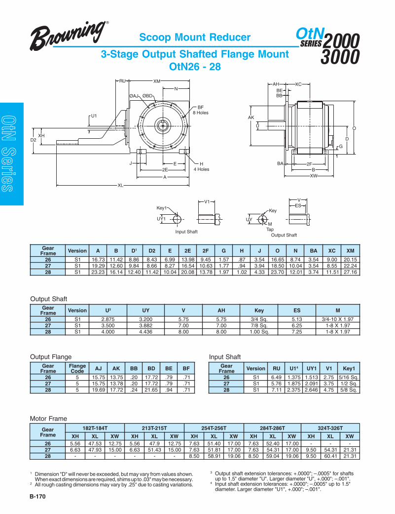
20003000
SERIESOtN
B-170
OtN Series
Scoop Mount Reducer
3-Stage Output Shafted Flange MountOtN26 - 28
Output Shaft
Motor Frame
1 Dimension "D" will never be exceeded, but may vary from values shown.When exact dimensions are required, shims up to .03" may be necessary.
2 All rough casting dimensions may vary by .25" due to casting variations.
Output Flange
3 Output shaft extension tolerances: +.0000"; –.0005" for shaftsup to 1.5" diameter "U". Larger diameter "U", +.000"; –.001".
4 Input shaft extension tolerances: +.0000"; –.0005" up to 1.5"diameter. Larger diameter "U1", +.000"; –.001".
Input Shaft
raeGemarF noisreV A B D1 2D E E2 F2 G H J O N AB CX MX
62 1S 37.61 24.11 68.8 34.8 99.6 89.31 54.9 75.1 78. 45.3 56.61 47.8 45.3 00.9 51.0272 1S 92.91 06.21 48.9 66.8 72.8 45.61 36.01 77.1 49. 49.3 05.81 40.01 45.3 55.8 42.2282 1S 32.32 41.61 04.21 24.11 40.01 80.02 87.31 79.1 20.1 33.4 07.32 10.21 47.3 15.11 61.72
raeGemarF noisreV U3 YU V HA yeK SE M
62 1S 578.2 002.3 57.5 57.5 .qS4/3 31.5 79.1X01-4/372 1S 005.3 288.3 00.7 00.7 .qS8/7 52.6 79.1X8-182 1S 000.4 634.4 00.8 00.8 .qS00.1 52.7 79.1X8-1
raeGemarF
egnalFedoC JA KA BB DB EB FB raeG
emarF noisreV UR 1U 4 1YU 1V 1yeK
62 5 57.51 57.31 02. 27.71 97. 17. 62 1S 94.6 573.1 315.1 57.2 .qS61/572 5 57.51 87.31 02. 27.71 97. 17. 72 1S 67.5 578.1 190.2 57.3 .qS2/182 5 96.91 27.71 42. 56.12 49. 17. 82 1S 11.7 573.2 646.2 57.4 .qS8/5
raeGemarF
T481-T281 T512-T312 T652-T452 T682-T482 T623-T423
HX LX WX HX LX WX HX LX WX HX LX WX HX LX WX62 65.5 35.74 57.21 65.5 9.74 57.21 36.7 04.15 00.71 36.7 04.25 00.71 - - -72 36.6 39.74 00.51 36.6 34.15 00.51 36.7 18.15 00.71 36.7 13.45 00.71 05.9 13.45 13.1282 - - - - - - 05.8 19.85 60.91 05.8 40.95 60.91 05.9 14.06 13.12
Key1
O
XCAHXM
A
UYM
Tap
ESV
Key
ØAJ
J
XH
E2E
N
BF8 Holes
H4 Holes
ØBD BB
BA
BE
AK
U
D
2FB
G
UY1
Input ShaftOutput Shaft
V1
XW
RU
U1
XL
D2

B-171
20003000
SERIESOtN
OtN SeriesScoop Mount Reducer
Combined Output Shafted Flange MountOtN26 - 28
raeGemarF noisreV A B D1 2D E E2 F2 G H J O N AB CX MX
A62 1S 37.61 24.11 68.8 66.7 99.6 89.31 54.9 75.1 78. 45.3 56.61 47.8 45.3 00.9 08.03A72 1S 92.91 06.21 48.9 98.7 72.8 45.61 36.01 77.1 49. 49.3 05.81 40.01 45.3 55.8 74.13A82 1S 32.32 41.61 04.21 04.01 40.01 80.02 87.31 79.1 20.1 33.4 07.32 10.21 47.3 15.11 94.73
raeGemarF noisreV U3 YU V HA yeK SE M
A62 1S 578.2 002.3 57.5 57.5 .qS4/3 31.5 79.1X01-4/3A72 1S 005.3 288.3 00.7 00.7 .qS8/7 52.6 79.1X8-1A82 1S 000.4 634.4 00.8 00.8 .qS00.1 52.7 79.1X8-1
Output Shaft
Motor Frame
1 Dimension "D" will never be exceeded, but may vary from values shown.When exact dimensions are required, shims up to .03" may be necessary.
2 All rough casting dimensions may vary by .25" due to casting variations.
Output Flange
3 Output shaft extension tolerances: +.0000"; –.0005" for shaftsup to 1.5" diameter "U". Larger diameter "U", +.000"; –.001".
4 Input shaft extension tolerances: +.0000"; –.0005" up to 1.5"diameter. Larger diameter "U1", +.000"; –.001".
Input ShaftraeGemarF
egnalFedoC JA KA BB DB EB FB raeG
emarF noisreV UR 1U 4 1YU 1V 1yeK
A62 5 57.51 57.31 02. 27.71 97. 17. A62 1S 57.4 521.1 632.1 52.2 .qS4/1A72 5 57.51 87.31 02. 27.71 97. 17. A72 1S 57.4 521.1 632.1 52.2 .qS4/1A82 5 96.91 27.71 42. 56.12 49. 17. A82 1S 30.5 521.1 632.1 52.2 .qS4/1
raeGemarF
T541-T341 T481-T281 T512-T312
HX LX WX HX LX WX HX LX WXA62 47.4 26.54 83.21 47.4 26.54 83.21 - - -A72 47.4 26.84 83.21 47.4 17.74 83.21 - - -A82 05.5 22.35 57.21 05.5 28.25 57.21 05.5 22.35 57.21
ESVV1
UYUY1
Input ShaftOutput Shaft
MTap
KeyKey1
XM
E
A
2E
N
BF8 Holes
H4 Holes
D2
J
ØAJ ØBD
XCAH
G
D
O
AK
U
BAB
2F
BBBE
U1
RU
XW
XH
XL

20003000
SERIESOtN
B-172
OtN Series
Scoop Mount Reducer
3-Stage Finished Bore Hollow ShaftOtN33 - 35
Output Shaft
Motor Frame
1 Dimension "D" will never be exceeded, but may vary from values shown.When exact dimensions are required, shims up to .03" may be necessary.
2 All rough casting dimensions may vary by .25" due to casting variations.3 Driven shaft entry can be from either side of the gear reducer housing
by reversing positioning of the snap rings and washer illustrated.4 Output finished bore tolerance: +.0020",-.0000 for all diameters.
Input Shaft
5 Output key supplied only on frame 34 “S2” version.6 Input shaft extension tolerances: +.0000"; –.0005" up to 1.5"
diameter. Larger diameter "U1", +.000"; –.001".7 Refer to Tapered Bushed designs if driven shaft varies from "U"
dimensions offered above.8 For details of the torque arm kit,refer to page B-114.
raeGemarF noisreV A B D1 2D E E2 F2 G H J O N GW MX
33 2S 05.8 16.6 15.5 42.5 81.1 27.4 15.5 58. 55. 68.2 96.9 45.3 37.3 79.1143 2S 31.01 78.7 90.7 09.5 75.1 19.5 05.6 70.1 17. 76.2 50.21 94.4 66.4 87.3153 2S 29.11 66.8 53.8 98.6 71.2 90.7 90.7 81.1 78. 54.3 85.31 02.5 51.5 59.51
raeGemarF noisreV HE U 7,4 YU AE FU GV HV yeK 5 M
33 2S 49.6 005.1 476.1 74.3 61.2 69.5 55. 4/12X8/3X8/3 57.1X11-8/543 2S 79.8 000.2 012.2 94.4 65.2 44.7 97. 8/52X61/7X2/1 57.1X11-8/553 2S 66.9 573.2 656.2 38.4 45.3 51.8 49. 8/53X8/5X8/5 00.2X01-4/3
raeGemarF noisreV UR 1U 6 1YU 1V 1yeK
33 2S 71.3 526. 507. 52.1 .qS61/343 2S 57.4 521.1 632.1 52.2 .qS4/153 2S 30.5 521.1 632.1 52.2 .qS4/1
raeGemarF
T541-T341 T481-T281 T512-T312
HX LX WX HX LX WX HX LX WX33 57.3 52.03 83.11 - - - - - -43 47.4 52.93 83.21 47.4 52.93 83.21 - - -53 05.5 16.24 57.21 05.5 16.14 57.21 05.5 10.24 57.21
RU
D2
Output Shaft
EA
2FB
A
EH
4 Holes2E
J
N
XM
D
O
G
WG
U1
UY1
Key1V1
Input Shaft
XW
XL
XH
UY UUF
M
VG
VH
Key EH

B-173
20003000
SERIESOtN
OtN SeriesScoop Mount Reducer
3-Stage Finished Bore Hollow ShaftOtN26 - 28
Motor Frame
1 Dimension "D" will never be exceeded, but may vary from values shown.When exact dimensions are required, shims up to .03" may be necessary.
2 All rough casting dimensions may vary by .25" due to casting variations.3 Driven shaft entry can be from either side of the gear reducer housing
by reversing positioning of the snap rings and washer illustrated.
Input Shaft
4 Output finished bore tolerance: +.0020",-.0000 for all diameters.5 Input shaft extension tolerances: +.0000"; –.0005" up to 1.5"
diameter. Larger diameter "U1", +.000"; –.001".6 For details of the torque arm kit,refer to page B-115.
EA
O
RU XM
B2F
UY
XL
D2
UF U
VG
M
VH
A
2E
E H4 Holes
J
EHKey
Output ShaftInput Shaft
G
D
N WG
Key1 V1
UY1
XW
U1
XH
raeGemarF noisreV A B D1 2D E E2 F2 G H J O N GW MX
62 1S 37.61 24.11 68.8 34.8 99.6 89.31 54.9 75.1 78. 45.3 56.61 47.8 79.6 51.0272 1S 92.91 06.21 48.9 66.8 72.8 45.61 36.01 77.1 49. 49.3 05.81 40.01 27.7 42.2282 1S 32.32 41.61 04.21 24.11 40.01 80.02 87.31 79.1 20.1 33.4 07.32 10.21 94.9 61.72
raeGemarF noisreV UR 1U 5 1YU 1V 1yeK
62 1S 94.6 573.1 315.1 57.2 .qS61/572 1S 67.5 578.1 190.2 57.3 .qS2/182 1S 11.7 573.2 646.2 57.4 .qS8/5
raeGemarF
T481-T281 T512-T312 T652-T452 T682-T482 T623-T423
HX LX WX HX LX WX HX LX WX HX LX WX HX LX WX62 65.5 35.74 57.21 65.5 9.74 57.21 36.7 04.15 00.71 36.7 04.25 00.71 - - -72 36.6 39.74 00.51 36.6 34.15 00.51 36.7 18.15 00.71 36.7 13.45 00.71 05.9 13.45 13.1282 - - - - - - 05.8 19.85 60.91 05.8 40.95 60.91 05.9 14.06 13.12
raeGemarF noisreV AE HE U4 FU YU GV HV yeK M
A62 1S 01.6 02.21 057.2 53.3 720.3 52.01 19. .qS8/5 01-4/3A72 1S 07.6 04.31 521.3 57.3 454.3 04.11 19. .qS4/3 01-4/3A82 1S 54.8 09.61 526.3 53.4 900.4 59.41 20.1 .qS8/7 8-1
Output Shaft

20003000
SERIESOtN
B-174
OtN Series
Scoop Mount Reducer
Combined Finished Bore Hollow ShaftOtN26 - 28
Motor Frame
1 Dimension "D" will never be exceeded, but may vary from values shown.When exact dimensions are required, shims up to .03" may be necessary.
2 All rough casting dimensions may vary by .25" due to casting variations.3 Driven shaft entry can be from either side of the gear reducer housing
by reversing positioning of the snap rings and washer illustrated.
Input Shaft
4 Output finished bore tolerance: +.0020",-.0000 for all diameters.5 Input shaft extension tolerances: +.0000"; –.0005" up to 1.5"
diameter. Larger diameter "U1", +.000"; –.001".6 For details of the torque arm kit,refer to page B-115.
raeGemarF noisreV A B D1 2D E E2 F2 G H J O N GW MX
A62 1S 37.61 24.11 68.8 66.7 99.6 89.31 54.9 75.1 78. 45.3 56.61 47.8 79.6 08.03A72 1S 92.91 06.21 48.9 98.7 72.8 45.61 36.01 77.1 49. 49.3 05.81 40.01 27.7 74.13A82 1S 32.32 41.61 04.21 04.01 40.01 80.02 87.31 79.1 20.1 33.4 07.32 10.21 94.9 94.73
raeGemarF noisreV UR 1U 5 1YU 1V 1yeK
A62 1S 57.4 521.1 632.1 52.2 .qS4/1A72 1S 57.4 521.1 632.1 52.2 .qS4/1A82 1S 30.5 521.1 632.1 52.2 .qS4/1
raeGemarF
T541-T341 T481-T281 T512-T312
HX LX WX HX LX WX HX LX WXA62 47.4 26.54 83.21 47.4 26.54 83.21 - - -A72 47.4 26.84 83.21 47.4 17.74 83.21 - - -A82 05.5 22.35 57.21 05.5 28.25 57.21 05.5 22.35 57.21
Key1
Input Shaft
Output Shaft
EA
O
RU
B2F
UY
XL
D2
UF U
VG
M
VH
A
2E
E H4 Holes
J
EHKey
G
D
N WG
U1
XW
V1
UY1
XH
XM
raeGemarF noisreV AE HE U4 FU YU GV HV yeK M
A62 1S 01.6 02.21 057.2 53.3 720.3 52.01 19. .qS8/5 01-4/3A72 1S 07.6 04.31 521.3 57.3 454.3 04.11 19. .qS4/3 01-4/3A82 1S 54.8 09.61 526.3 53.4 900.4 59.41 20.1 .qS8/7 8-1
Output Shaft

B-175
20003000
SERIESOtN
OtN SeriesScoop Mount Reducer
3-Stage Finished Bore Hollow Shaft Face MountOtN33 - 35
Output Shaft
Motor Frame
1 Dimension "D" will never be exceeded, but may vary from values shown.When exact dimensions are required, shims up to .03" may be necessary.
2 All rough casting dimensions may vary by .25" due to casting variations.3 Driven shaft entry can be from either side of the gear reducer housing
by reversing positioning of the snap rings and washer illustrated.
Input Shaft
4 Output key supplied only on frame 34 “S2” version.5 Output finished bore tolerance: +.0020",-.0000 for all diameters.6 Input shaft extension tolerances: +.0000"; –.0005" up to 1.5"
diameter. Larger diameter "U1", +.000"; –.001".
UY1
Key1
Input Shaft
V1
Output Shaft
UY UUFM
VG
VH
Key EH
RU
D2
BBBE
ØAJ
NXC WG
XM
BAJ
A
H4 Holes
BF4 Holes
2E
E
ØAK
G
B2F
O
D
ØBD
U1
XW
XL
XH
EA
44°44°
25°25°
Gear Frame - Size 35
ØAJ
AHBB
AK
MF Tap44°
25°25°
Gear Frame - Size 34
55° ØAJ
46°
44°
40°
52°
59°30°
23°
Gear Frame - Size 33
68°
45°
AH
BB
AK
MF TapØAJ 23°
44°
45°
raeGemarF noisreV A B D1 2D E E2 F2 G H J O N GW MX
33 2S 05.8 16.6 15.5 42.5 81.1 27.4 15.5 58. 55. 68.2 96.9 45.3 36.3 79.1143 2S 31.01 78.7 90.7 09.5 75.1 19.5 05.6 70.1 17. 76.2 50.21 94.4 66.4 87.3153 2S 29.11 66.8 53.8 98.6 71.2 90.7 90.7 81.1 78. 54.3 85.31 02.5 51.5 59.51
raeGemarF noisreV AE HE U5 FU YU GV HV yeK 4 M
33 2S 74.3 49.6 005.1 61.2 476.1 69.5 55. 4/12X8/3X8/3 57.1X11-8/543 2S 94.4 79.8 000.2 65.2 012.2 44.7 97. 8/52X61/7X2/1 57.1X11-8/553 2S 38.4 66.9 573.2 45.3 656.2 51.8 49. 8/53X8/5X8/5 00.2X01-4/3
raeGemarF noisreV HA JA KA BB FM raeG
emarF noisreV UR 1U 6 1YU 1V YEK 1
33 2S 21. 48.4 49.3 61. 78.X21M 33 2S 71.3 526. 507. 52.1 .qS61/343 2S 41. 89.5 21.5 82. 78.X01M 43 2S 57.4 521.1 632.1 52.2 .qS4/153 2S 31. 84.7 01.6 82. 78.X21M 53 2S 30.5 521.1 632.1 52.2 .qS4/1
raeGemarF
T541-T341 T481-T281 T512-T312
HX LX WX HX LX WX HX LX WX33 57.3 52.03 83.11 - - - - - -43 47.4 52.93 83.21 47.4 52.93 83.21 - - -53 05.5 16.24 57.21 05.5 16.14 57.21 05.5 10.24 57.21
Output Face

20003000
SERIESOtN
B-176
OtN Series
Scoop Mount Reducer
3-Stage Finished Bore Hollow Shaft Face MountOtN26 - 28
Output Shaft
Motor Frame
1 Dimension "D" will never be exceeded, but may vary from values shown.When exact dimensions are required, shims up to .03" may be necessary.
2 All rough casting dimensions may vary by .25" due to casting variations.3 Driven shaft entry can be from either side of the gear reducer housing
by reversing positioning of the snap rings and washer illustrated.
Input Shaft
4 Output finished bore tolerance: +.0020",-.0000 for all diameters.5 Input shaft extension tolerances: +.0000"; –.0005" up to 1.5"
diameter. Larger diameter "U1", +.000"; –.001".
Output Face
raeGemarF noisreV A B D1 2D E E2 F2 G H J O N GW MX
62 1S 37.61 24.11 68.8 34.8 99.6 89.31 54.9 75.1 78. 45.3 56.61 47.8 79.6 51.0272 1S 92.91 06.21 48.9 66.8 72.8 45.61 36.01 77.1 49. 49.3 05.81 40.01 27.7 42.2282 1S 32.32 41.61 04.21 24.11 40.01 80.02 87.31 79.1 20.1 33.4 07.32 10.21 94.9 61.72
raeGemarF noisreV AE HE U4 FU YU GV HV yeK M
62 1S 01.6 02.21 057.2 53.3 720.3 52.01 19. .qS8/5 52.1X01-4/372 1S 07.6 04.31 521.3 57.3 454.3 04.11 19. .qS4/3 52.1X01-4/382 1S 54.8 09.61 526.3 53.4 900.4 59.41 20.1 .qS8/7 52.1X8-1
raeGemarF noisreV JA KA BB DB FB raeG
emarF noisreV UR 1U 5 1YU 1V 1yeK
62 1S 18.11 48.9 02. 87.31 22X61M 62 1S 94.6 573.1 315.1 57.2 .qS61/572 1S 87.31 18.11 02. 57.51 22X61M 72 1S 67.5 578.1 190.2 57.3 .qS2/182 1S 57.51 87.31 02. 27.71 22X61M 82 1S 11.7 573.2 646.2 57.4 .qS8/5
raeGemarF
T481-T281 T512-T312 T652-T452 T682-T482 T623-T423
HX LX WX HX LX WX HX LX WX HX LX WX HX LX WX62 65.5 35.74 57.21 65.5 9.74 57.21 36.7 04.15 00.71 36.7 04.25 00.71 - - -72 36.6 39.74 00.51 36.6 34.15 00.51 36.7 18.15 00.71 36.7 13.45 00.71 05.9 13.45 13.1282 - - - - - - 05.8 19.85 60.91 05.8 40.95 60.91 05.9 14.06 13.12
XW
EA
2F
B
XL
D2
2EA
EH
VGOutput Shaft
UUF UY
M
VH
Key
H4 Holes
BF8 Holes
N
XM
E
RU
J
ØAJ ØBD
ØAK
BB
O
D
G
WG
U1
V1
UY1
Input Shaft
Key1
XH

B-177
20003000
SERIESOtN
OtN SeriesScoop Mount Reducer
Combined Finished Bore Hollow Shaft Face MountOtN26 - 28
Output Shaft
Motor Frame
1 Dimension "D" will never be exceeded, but may vary from values shown.When exact dimensions are required, shims up to .03" may be necessary.
2 All rough casting dimensions may vary by .25" due to casting variations.3 Driven shaft entry can be from either side of the gear reducer housing
by reversing positioning of the snap rings and washer illustrated.
Input Shaft
4 Output finished bore tolerance: +.0020",-.0000 for all diameters.5 Input shaft extension tolerances: +.0000"; –.0005" up to 1.5"
diameter. Larger diameter "U1", +.000"; –.001".
Output Face
raeGemarF noisreV A B D1 2D E E2 F2 G H J O N GW MX
A62 1S 37.61 24.11 68.8 66.7 99.6 89.31 54.9 75.1 78. 45.3 56.61 47.8 79.6 08.03A72 1S 92.91 06.21 48.9 98.7 72.8 45.61 36.01 77.1 49. 49.3 05.81 40.01 27.7 74.13A82 1S 32.32 41.61 04.21 04.01 40.01 80.02 87.31 79.1 20.1 33.4 07.32 10.21 94.9 94.73
raeGemarF noisreV JA KA BB DB FB raeG
emarF noisreV UR 1U 5 1YU 1V 1yeK
A62 1S 18.11 48.9 02. 87.31 22X61M A62 1S 57.4 521.1 632.1 52.2 .qS4/1A72 1S 87.31 18.11 02. 57.51 22X61M A72 1S 57.4 521.1 632.1 52.2 .qS4/1A82 1S 57.51 87.31 02. 27.71 22X61M A82 1S 30.5 521.1 632.1 52.2 .qS4/1
raeGemarF
T541-T341 T481-T281 T512-T312
HX LX WX HX LX WX HX LX WXA62 47.4 26.54 83.21 47.4 26.54 83.21 - - -A72 47.4 26.84 83.21 47.4 17.74 83.21 - - -A82 05.5 22.35 57.21 05.5 28.25 57.21 05.5 22.35 57.21
N
E
2E
A
H4 Holes
BF8 Holes
EH
XM
VG Output Shaft
UUF
RU
J
ØAJ ØBD
KeyM
VH
UY
WG
O
EA
BB
2FB
ØAK
G
D
U1
D2
XL
XW
Key1V1
UY1
Input Shaft
XH
raeGemarF noisreV AE HE U4 FU YU GV HV yeK M
A62 1S 01.6 02.21 057.2 53.3 720.3 52.01 19. .qS8/5 01-4/3A72 1S 07.6 04.31 521.3 57.3 454.3 04.11 19. .qS4/3 01-4/3A82 1S 54.8 09.61 526.3 53.4 900.4 59.41 20.1 .qS8/7 8-1

20003000
SERIESOtN
B-178
OtN Series
Scoop Mount Reducer
3-Stage Finished Bore Hollow Shaft Flange MountOtN33 - 35
Output Shaft
Motor Frame
1 Dimension "D" will never be exceeded, but may vary from values shown.When exact dimensions are required, shims up to .03" may be necessary.
2 All rough casting dimensions may vary by .25" due to casting variations.3 Driven shaft entry can be from either side of the gear reducer housing
by reversing positioning of the snap rings and washer illustrated.
Input Shaft
4 Output key supplied only on frame 34 “S2” version.5 Output finished bore tolerance: +.0020",-.0000 for all diameters.6 Input shaft extension tolerances: +.0000"; –.0005" up to 1.5"
diameter. Larger diameter "U1", +.000"; –.001".
Output Flange
raeGemarF noisreV A B D1 2D E E2 F2 G H J O N AB GW CX MX
33 2S 05.8 16.6 15.5 42.5 81.1 27.4 15.5 58. 55. 68.2 96.9 45.3 80.2 37.3 48.4 79.1143 2S 31.01 78.7 90.7 09.5 75.1 19.5 05.6 70.1 17. 76.2 50.21 94.4 39.1 66.4 81.5 87.3153 2S 29.11 66.8 53.8 98.6 71.2 90.7 90.7 81.1 78. 54.3 85.31 02.5 22.2 51.5 77.5 59.51
raeGemarF noisreV AE HE U5 FU YU GV HV yeK 4 M
33 2S 74.3 49.6 005.1 61.2 476.1 69.5 55. 4/12X8/3X8/3 57.1X11-8/543 2S 94.4 79.8 000.2 65.2 012.2 44.7 97. 8/52X61/7X2/1 57.1X11-8/553 2S 38.4 66.9 573.2 45.3 656.2 51.8 49. 8/53X8/5X8/5 00.2X01-4/3
raeGemarF
egnalFedoC KA JA BB DB EB FB raeG
emarF noisreV UR 1U 6 1YU 1V 1yeK
335 780.7 64.8 61. 48.9 74. 55. 33 2S 71.3 526. 507. 52.1 .qS61/36 550.9 34.01 61. 18.11 74. 55. 43 2S 57.4 521.1 632.1 52.2 .qS4/1
43 5 550.9 34.01 61. 18.11 95. 55. 53 2S 30.5 521.1 632.1 52.2 .qS4/16 248.9 08.11 61. 77.31 95. 17.
535 248.9 08.11 02. 77.31 17. 17.6 018.11 77.31 02. 57.51 17. 17.
raeGemarF
T541-T341 T481-T281 T512-T312
HX LX WX HX LX WX HX LX WX33 57.3 52.03 83.11 - - - - - -43 47.4 52.93 83.21 47.4 52.93 83.21 - - -53 05.5 16.24 57.21 05.5 16.14 57.21 05.5 10.24 57.21
RU
D2
BBBE
ØAJ
NXC WG
XM
BAJ
A
H4 Holes
BF4 Holes
2E
E
ØAK
G
B2F
O
D
ØBD
U1
XW
XL
UY1
Key1
Input ShaftOutput Shaft
V1
UY UUF
M
VG
VH
Key EH
XH
EA

B-179
20003000
SERIESOtN
OtN SeriesScoop Mount Reducer
3-Stage Finished Bore Hollow Shaft Flange MountOtN26 - 28
Output Shaft
Motor Frame
1 Dimension "D" will never be exceeded, but may vary from values shown.When exact dimensions are required, shims up to .03" may be necessary.
2 All rough casting dimensions may vary by .25" due to casting variations.3 Driven shaft entry can be from either side of the gear reducer housing
by reversing positioning of the snap rings and washer illustrated.
Input Shaft
4 Output finished bore tolerance: +.0020",-.0000 for all diameters.5 Input shaft extension tolerances: +.0000"; –.0005" up to 1.5"
diameter. Larger diameter "U1", +.000"; –.001".
Output Flange
raeGemarF noisreV A B D1 2D E E2 F2 G H J O N AB GW CX MX
62 1S 37.61 24.11 68.8 34.8 99.6 89.31 54.9 75.1 78. 45.3 56.61 47.8 45.3 79.6 00.9 51.0272 1S 92.91 06.21 48.9 66.8 72.8 45.61 36.01 77.1 49. 49.3 05.81 40.01 45.3 27.7 55.8 42.2282 1S 32.32 41.61 04.21 24.11 40.01 80.02 87.31 79.1 20.1 33.4 07.32 10.21 47.3 94.9 15.11 61.72
raeGemarF noisreV AE HE U4 FU YU GV HV yeK M
62 1S 01.6 02.21 057.2 53.3 720.3 52.01 19. .qS8/5 01-4/372 1S 07.6 04.31 521.3 57.3 454.3 04.11 19. .qS4/3 01-4/382 1S 54.8 09.61 526.3 53.4 900.4 59.41 20.1 .qS8/7 8-1
raeGemarF
egnalFedoC JA KA BB DB EB FB raeG
emarF noisreV UR 1U 5 1YU 1V 1yeK
62 5 57.51 57.31 02. 27.71 97. 17. 62 1S 94.6 573.1 315.1 57.2 .qS61/572 5 57.51 87.31 02. 27.71 97. 17. 72 1S 67.5 578.1 190.2 57.3 .qS2/182 5 96.91 27.71 42. 56.12 49. 17. 82 1S 11.7 573.2 646.2 57.4 .qS8/5
raeGemarF
T481-T281 T512-T312 T652-T452 T682-T482 T623-T423
HX LX WX HX LX WX HX LX WX HX LX WX HX LX WX62 65.5 35.74 57.21 65.5 9.74 57.21 36.7 04.15 00.71 36.7 04.25 00.71 - - -72 36.6 39.74 00.51 36.6 34.15 00.51 36.7 18.15 00.71 36.7 13.45 00.71 05.9 13.45 13.1282 - - - - - - 05.8 19.85 60.91 05.8 40.95 60.91 05.9 14.06 13.12
VG
D2
J
A
H4 Holes
BF8 Holes
E
2E
ØAJ
XM
NØBD
D
O
AK
EH
B2F
UUF
BA
VH
M
UY
Key
G
EA
XCBE
BBWG
XL
XW
RU
U1
V1
UY1
Input ShaftOutput Shaft
Key1
XH

20003000
SERIESOtN
B-180
OtN Series
Scoop Mount Reducer
Combined Finished Bore Hollow Shaft Flange MountOtN26 - 28
Output Shaft
Motor Frame
1 Dimension "D" will never be exceeded, but may vary from values shown.When exact dimensions are required, shims up to .03" may be necessary.
2 All rough casting dimensions may vary by .25" due to casting variations.3 Driven shaft entry can be from either side of the gear reducer housing
by reversing positioning of the snap rings and washer illustrated.
Input Shaft
4 Output finished bore tolerance: +.0020",-.0000 for all diameters.5 Input shaft extension tolerances: +.0000"; –.0005" up to 1.5"
diameter. Larger diameter "U1", +.000"; –.001".
Output Flange
raeGemarF noisreV A B D1 2D E E2 F2 G H J O N AB GW CX MX
A62 1S 37.61 24.11 68.8 66.7 99.6 89.31 54.9 75.1 78. 45.3 56.61 47.8 45.3 79.6 00.9 08.03A72 1S 92.91 06.21 48.9 98.7 72.8 45.61 36.01 77.1 49. 49.3 05.81 40.01 45.3 27.7 55.8 74.13A82 1S 32.32 41.61 04.21 04.01 40.01 80.02 87.31 79.1 20.1 33.4 07.32 10.21 47.3 94.9 15.11 94.73
raeGemarF
egnalFedoC JA KA BB DB EB FB raeG
emarF noisreV UR 1U 5 1YU 1V 1yeK
A62 5 57.51 57.31 02. 27.71 97. 17. A62 1S 57.4 521.1 632.1 52.2 .qS4/1A72 5 57.51 87.31 02. 27.71 97. 17. A72 1S 57.4 521.1 632.1 52.2 .qS4/1A82 5 96.91 27.71 42. 56.12 49. 17. A82 1S 30.5 521.1 632.1 52.2 .qS4/1
raeGemarF
T541-T341 T481-T281 T512-T312
HX LX WX HX LX WX HX LX WXA62 47.4 26.54 83.21 47.4 26.54 83.21 - - -A72 47.4 26.84 83.21 47.4 17.74 83.21 - - -A82 05.5 22.35 57.21 05.5 28.25 57.21 05.5 22.35 57.21
VG
J
A
E H4 Holes2E
ØAJ
XM
NØBD
D
O
AK
BF8 Holes
EH
B2F
UUF
BA
VH
M
UY
Key
G
EA
XCBE
BBWG
U1
D2
RU
XL
XW
V1
UY1
Input Shaft
Output Shaft
Key1
XH
raeGemarF noisreV AE HE U5 FU YU GV HV yeK 4 M
A62 1S 01.6 02.21 057.2 53.3 720.3 52.01 19. .qS8/5 01-4/3A72 1S 07.6 04.31 521.3 57.3 454.3 04.11 19. .qS4/3 01-4/3A82 1S 54.8 09.61 526.3 53.4 900.4 59.41 20.1 .qS8/7 8-1
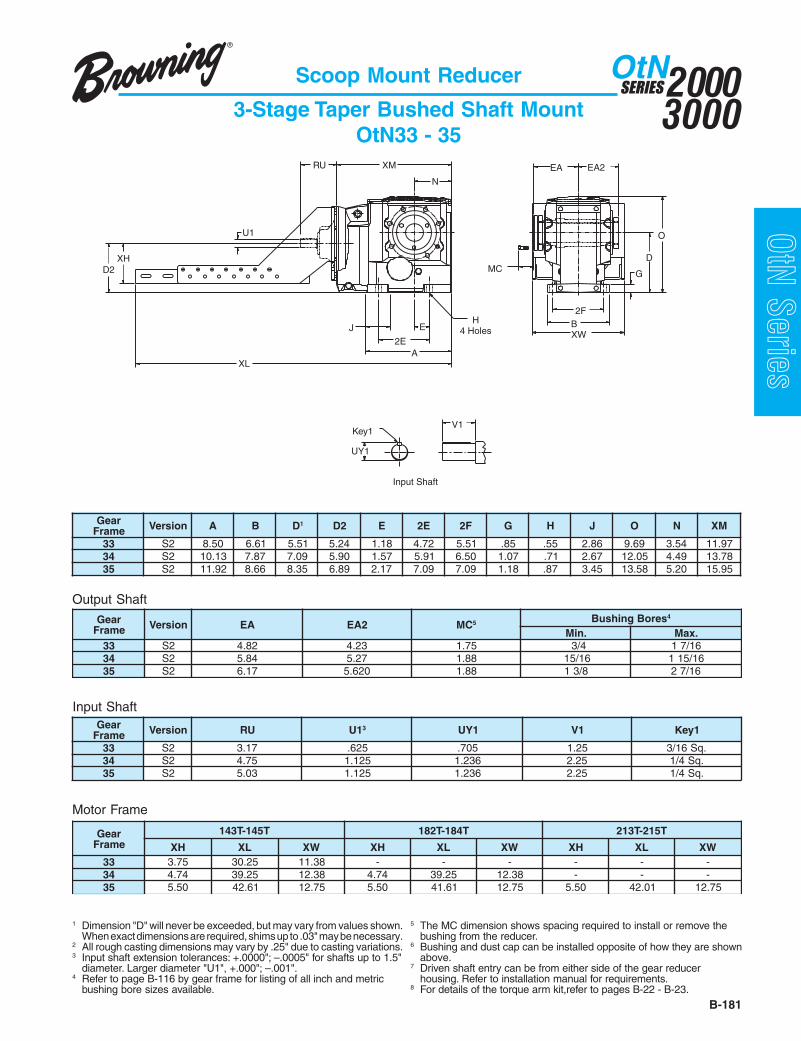
B-181
20003000
SERIESOtN
OtN Series
EA EA2XM
N
O
D
A
H4 Holes
2E
J
2FBE
MC G
UY1
Key1V1
Input Shaft
RU
U1
D2
XW
XL
XH
Scoop Mount Reducer
3-Stage Taper Bushed Shaft MountOtN33 - 35
Output Shaft
Motor Frame
Input Shaft
raeGemarF noisreV A B D1 2D E E2 F2 G H J O N MX
33 2S 05.8 16.6 15.5 42.5 81.1 27.4 15.5 58. 55. 68.2 96.9 45.3 79.1143 2S 31.01 78.7 90.7 09.5 75.1 19.5 05.6 70.1 17. 76.2 50.21 94.4 87.3153 2S 29.11 66.8 53.8 98.6 71.2 90.7 90.7 81.1 78. 54.3 85.31 02.5 59.51
raeGemarF noisreV AE 2AE CM 5 seroBgnihsuB 4
.niM .xaM33 2S 28.4 32.4 57.1 4/3 61/7143 2S 48.5 72.5 88.1 61/51 61/51153 2S 71.6 026.5 88.1 8/31 61/72
raeGemarF noisreV UR 1U 3 1YU 1V 1yeK
33 2S 71.3 526. 507. 52.1 .qS61/343 2S 57.4 521.1 632.1 52.2 .qS4/153 2S 30.5 521.1 632.1 52.2 .qS4/1
raeGemarF
T541-T341 T481-T281 T512-T312
HX LX WX HX LX WX HX LX WX33 57.3 52.03 83.11 - - - - - -43 47.4 52.93 83.21 47.4 52.93 83.21 - - -53 05.5 16.24 57.21 05.5 16.14 57.21 05.5 10.24 57.21
1 Dimension "D" will never be exceeded, but may vary from values shown.When exact dimensions are required, shims up to .03" may be necessary.
2 All rough casting dimensions may vary by .25" due to casting variations.3 Input shaft extension tolerances: +.0000"; –.0005" for shafts up to 1.5"
diameter. Larger diameter "U1", +.000"; –.001".4 Refer to page B-116 by gear frame for listing of all inch and metric
bushing bore sizes available.
5 The MC dimension shows spacing required to install or remove thebushing from the reducer.
6 Bushing and dust cap can be installed opposite of how they are shownabove.
7 Driven shaft entry can be from either side of the gear reducerhousing. Refer to installation manual for requirements.
8 For details of the torque arm kit,refer to pages B-22 - B-23.

20003000
SERIESOtN
B-182
OtN Series
Top Mount Reducer
3-Stage Output Shafted Foot MountOtN33 - 35
Output Shaft
1 Dimension "D" will never be exceeded, but may vary from values shown.When exact dimensions are required, shims up to .03" may be necessary.
2 All rough casting dimensions may vary by .25" due to casting variations.
3 Output shaft extension tolerances: +.0000"; –.0005" for shaftsup to 1.5" diameter "U". Larger diameter "U", +.000"; –.001".
4 Input shaft extension tolerances: +.0000"; –.0005" up to 1.5"diameter. Larger diameter "U1", +.000"; –.001".
Input Shaft
RU
D2
EA
AH
O
EA
XM
B2F
A
MTap
Key
UY
VES
J E
2E
U
DG
N H4 Holes
TL TW
HS
HTCenterDistance
LS
9.00
V1
UY1
Input Shaft
Output Shaft
Key1
U1
raeGemarF noisreV A B D1 2D E E2 F2 G H J O N MX SL SH TH LT WT
332S 05.8 16.6 15.5 42.5 81.1 27.4 15.5 58. 55. 68.2 96.9 45.3 79.11
92.1 41.7 00.6 05.51 05.611S 80.8 85.8 29.4 02.5 53.3 96.6 01.6 97. 55. 72.2 34.01 45.3 79.11
432S 31.01 78.7 90.7 09.5 75.1 19.5 05.6 70.1 17. 76.2 50.21 94.4 87.31
13.2 71.7 00.6 05.51 05.611S 96.01 06.9 03.6 94.7 35.4 60.9 86.7 81.1 17. 91.3 93.31 94.4 87.31
532S 29.11 66.8 53.8 98.6 71.2 90.7 90.7 81.1 78. 73.3 85.31 02.5 59.51
53.2 84.8 00.6 05.51 05.611S 70.31 89.01 78.7 33.9 15.5 20.11 60.9 04.1 78. 50.4 22.61 02.5 59.51
raeGemarF noisreV U3 YU V HA AE yeK SE M
332S 526.1 387.1 52.3 93.3 37.6 .qS8/3 87.2 83.1X11-8/51S 005.1 756.1 81.3 91.3 21.7 .qS8/3 87.2 83.1X11-8/5
432S 000.2 012.2 36.3 67.3 11.8 .qS2/1 60.3 16.1X01-4/31S 057.1 909.1 65.3 66.3 64.8 .qS8/3 65.3 16.1X01-4/3
532S 573.2 836.2 16.4 47.4 54.9 .qS8/5 18.3 16.1X01-4/31S 573.2 836.2 37.5 72.5 75.01 .qS8/5 18.4 16.1X01-4/3
raeGemarF noisreV UR 1U 4 1YU 1V 1yeK
33 2S,1S 71.3 526. 07. 52.1 .qS61/343 2S,1S 57.4 521.1 42.1 52.2 .qS4/153 2S,1S 30.5 521.1 42.1 52.2 .qS4/1
rotoMemarF
33 43 53
ecnatsiDretneC ecnatsiDretneC ecnatsiDretneC.niM .xaM .niM .xaM .niM .xaM
65 82.21 52.81 13.21 82.81 - -T541/T341 82.21 52.81 13.21 82.81 78.31 43.91T481/T281 82.31 52.91 13.31 82.91 78.41 43.02T512/T312 - - 60.41 30.02 26.51 90.12T652/T452 - - - - 26.61 90.22

B-183
20003000
SERIESOtN
OtN Series
D
O
2FB
G
EA WGCenter
Distance
HS
J
D2
N H4 Holes
E
TL
HT
LS
9.00
TW
XMA
2E
RU
UY1
Input Shaft
Key1 V1
U1
Output Shaft
UY UUFM
VG
VH
Key EH
Top Mount Reducer
3-Stage Finished Bore Hollow ShaftOtN33 - 35
Output Shaft
Input Shaft
raeGemarF noisreV A B D1 2D E E2 F2 G H J O N GW MX SL SH TH LT WT
33 2S 05.8 16.6 15.5 42.5 81.1 27.4 15.5 58. 55. 68.2 96.9 45.3 37.3 79.11 92.1 41.7 00.6 05.51 05.6143 2S 31.01 78.7 90.7 09.5 75.1 19.5 05.6 70.1 17. 76.2 50.21 94.4 66.4 87.31 13.2 71.7 00.6 05.51 05.6153 2S 29.11 66.8 53.8 98.6 71.2 90.7 90.7 81.1 78. 54.3 85.31 02.5 51.5 59.51 53.2 84.8 00.6 05.51 05.61
raeGemarF noisreV UR 1U 6 1YU 1V 1yeK
33 2S 71.3 526. 07. 52.1 .qS61/343 2S 57.4 521.1 42.1 52.2 .qS4/153 2S 30.5 521.1 42.1 52.2 .qS4/1
rotoMemarF
33 43 53
ecnatsiDretneC ecnatsiDretneC ecnatsiDretneC.niM .xaM .niM .xaM .niM .xaM
65 82.21 52.81 13.21 82.81 - -T541/T341 82.21 52.81 13.21 82.81 78.31 43.91T481/T281 82.31 52.91 13.31 82.91 78.41 43.02T512/T312 - - 60.41 30.02 26.51 90.12T652/T452 - - - - 26.61 90.22
1 Dimension "D" will never be exceeded, but may vary from values shown.When exact dimensions are required, shims up to .03" may be necessary.
2 All rough casting dimensions may vary by .25" due to casting variations.3 Driven shaft entry can be from either side of the gear reducer housing
by reversing positioning of the snap rings and washer illustrated.4 Output finished bore tolerance: +.0020",-.0000 for all diameters.
5 Output key supplied only on frame 34 “S2” version.6 Input shaft extension tolerances: +.0000"; –.0005" up to 1.5"
diameter. Larger diameter "U1", +.000"; –.001".7 Refer to Tapered Bushed designs if driven shaft varies from "U"
dimensions offered above.8 For details of the torque arm kit,refer to page B-114.
raeGemarF noisreV AE HE U 7,4 FU YU GV HV yeK 5 M
33 2S 74.3 49.6 005.1 61.2 476.1 69.5 55. 4/12X8/3X8/3 57.1X11-8/543 2S 94.4 79.8 000.2 65.2 012.2 44.7 97. 8/52X61/7X2/1 57.1X11-8/553 2S 38.4 66.9 573.2 45.3 656.2 51.8 49. 8/53X8/5X8/5 00.2X01-4/3

20003000
SERIESOtN
B-184
OtN Series
Top Mount Reducer
3-Stage Finished Bore Hollow Shaft Face MountOtN33 - 35
Output Shaft
2FB
EA
D
O
G
WG
J
TL
HTCenterDistance
HS
D2
LS
9.00
EN H
4 Holes
TW
2EA
XMRU
Input Shaft
V1
UY1Key1
U1
44°44°
25°25°
Gear Frame - Size 35
ØAJ
AHBB
AK
MF Tap44°
25°25°
Gear Frame - Size 34
55° ØAJ
46°
44°
40°
52°
59°30°
23°
Gear Frame - Size 33
68°
45°
AH
BB
AK
MF TapØAJ
23°44°
45°
Output Shaft
UY UUFM
VG
VH
Key EH
raeGemarF noisreV A B D1 2D E E2 F2 G H J O N GW MX SL SH TH LT WT
33 2S 05.8 16.6 15.5 42.5 81.1 27.4 15.5 58. 55. 68.2 96.9 45.3 36.3 79.11 92.1 41.7 00.6 05.51 05.61
43 2S 31.01 78.7 90.7 09.5 75.1 19.5 05.6 70.1 17. 76.2 50.21 94.4 66.4 87.31 13.2 71.7 00.6 05.51 05.61
53 2S 29.11 66.8 53.8 98.6 71.2 90.7 90.7 81.1 78. 54.3 85.31 02.5 51.5 59.51 53.2 84.8 00.6 05.51 05.61
raeGemarF noisreV AE HE U5 FU YU GV HV yeK 4 M
33 2S 74.3 49.6 005.1 61.2 476.1 69.5 55. 4/12X8/3X8/3 57.1X11-8/543 2S 94.4 79.8 000.2 65.2 012.2 44.7 97. 8/52X61/7X2/1 57.1X11-8/553 2S 38.4 66.9 573.2 45.3 836.2 51.8 49. 8/53X8/5X8/5 00.2X01-4/3
Input ShaftOutput FaceraeGemarF noisreV HA JA KA BB FM raeG
emarF noisreV UR 1U 6 1YU 1V 1yeK
33 2S 21. 48.4 49.3 61. 78.X21M 33 2S 71.3 526. 507. 52.1 .qS61/343 2S 41. 89.5 21.5 82. 78.X01M 43 2S 57.4 521.1 632.1 52.2 .qS4/153 2S 31. 84.7 01.6 82. 78.X21M 53 2S 30.5 521.1 632.1 52.2 .qS4/1
rotoMemarF
33 43 53
ecnatsiDretneC ecnatsiDretneC ecnatsiDretneC.niM .xaM .niM .xaM .niM .xaM
65 82.21 52.81 13.21 82.81 - -T541/T341 82.21 52.81 13.21 82.81 78.31 43.91T481/T281 82.31 52.91 13.31 82.91 78.41 43.02T512/T312 - - 60.41 30.02 26.51 90.12T652/T452 - - - - 26.61 90.22
1 Dimension "D" will never be exceeded, but may vary from values shown.When exact dimensions are required, shims up to .03" may be necessary.
2 All rough casting dimensions may vary by .25" due to casting variations.3 Driven shaft entry can be from either side of the gear reducer housing
by reversing positioning of the snap rings and washer illustrated.
4 Output key supplied only on frame 34 “S2” version.5 Output finished bore tolerance: +.0020",-.0000 for all diameters.6 Input shaft extension tolerances: +.0000"; –.0005" up to 1.5"
diameter. Larger diameter "U1", +.000"; –.001".

B-185
20003000
SERIESOtN
OtN SeriesTop Mount Reducer
3-Stage Taper Bushed Shaft MountOtN33 - 35
Output Shaft
Input Shaft
raeGemarF noisreV A B D1 2D E E2 F2 G H J O N MX SL SH TH LT WT
33 2S 05.8 16.6 15.5 42.5 81.1 27.4 15.5 58. 55. 68.2 96.9 45.3 79.11 92.1 41.7 00.6 05.51 05.6143 2S 31.01 78.7 90.7 09.5 75.1 19.5 05.6 70.1 17. 76.2 50.21 94.4 87.31 13.2 71.7 00.6 05.51 05.6153 2S 29.11 66.8 53.8 98.6 71.2 90.7 90.7 81.1 78. 54.3 85.31 02.5 59.51 53.2 84.8 00.6 05.51 05.61
raeGemarF noisreV AE 2AE CM 5 seroBgnihsuB 4
.niM .xaM33 2S 28.4 32.4 57.1 4/3 61/7143 2S 48.5 72.5 88.1 61/51 61/51153 2S 71.6 026.5 88.1 8/31 61/72
raeGemarF noisreV UR 1U 3 1YU 1V 1yeK
33 2S 71.3 526. 07. 52.1 .qS61/343 2S 57.4 521.1 42.1 52.2 .qS4/153 2S 30.5 521.1 42.1 52.2 .qS4/1
rotoMemarF
33 43 53
ecnatsiDretneC ecnatsiDretneC ecnatsiDretneC.niM .xaM .niM .xaM .niM .xaM
65 82.21 52.81 13.21 82.81 - -T541/T341 82.21 52.81 13.21 82.81 78.31 43.91T481/T281 82.31 62.91 13.31 82.91 78.41 43.02T512/T312 - - 60.41 30.02 26.51 90.12T652/T452 - - - - 26.61 90.22
1 Dimension "D" will never be exceeded, but may vary from values shown.When exact dimensions are required, shims up to .03" may be necessary.
2 All rough casting dimensions may vary by .25" due to casting variations.3 Input shaft extension tolerances: +.0000"; –.0005" for shafts up to 1.5"
diameter. Larger diameter "U1", +.000"; –.001".4 Refer to page B-116 by gear frame for listing of all inch and metric
bushing bore sizes available.
5 The MC dimension shows spacing required to install or remove thebushing from the reducer.
6 Bushing and dust cap can be installed opposite of how they are shownabove.
7 Driven shaft entry can be from either side of the gear reducerhousing. Refer to installation manual for requirements.
8 For details of the torque arm kit,refer to page B-22.
ØU1
Key1
Input Shaft
EA
B
MC
H4 Holes 2F
G
D
O
EA2Center
Distance
HS
J
D2
NE
TL
HT
LS
9.00
TW
UY1
Key1
Input Shaft
V1
XMA
2E
RU
U1

20003000
SERIESOtN
B-186
OtN Series
Reducer Weights
C-Face Reducers
raeGemarF
noitcudeRsegatS
eziStupnI
C65 CT041 CT081 CT012 CT052 CT082 CT023
233 65 65 26 - - - -
5 46 46 - - - - -
333 86 86 77 77 - - -
6,5 89 89 - - - - -
433 811 811 721 721 - - -
6,5 741 741 - - - - -
533 091 091 991 991 402 602 -
6,5 012 012 912 - - - -
623 - 153 063 063 563 763 -
6,5 104 104 914 914 - - -
723 - - 045 045 545 745 575
6,5 675 675 585 585 - - -
823 - - - 058 558 758 588
6,5 068 068 968 968 - - -
srecudeRtfahStupnI
raeGemarF
noitcudeRsegatS
elytS
DA/PA poocS .tMpoT snoitpOraeGthgieWlanoitiddA
233 25 - -
5 06 - - raeGemarF
egnalFtnuoM
detooF1S
333 47 99 121
6,5 401 - - 23 4 -
433 321 651 071 33 5 2
6,5 151 - - 43 7 3
533 591 742 662 53 8 5
6,5 512 - - 62 01 -
623 363 504 OR 72 21 -
6,5 514 844 264 82 51 -
723 855 875 OR
6,5 206 536 946
823 077 368 OR
6,5 987 148 958
gnireenignEnoitacilppAotrefeROR

B-187
20003000
SERIESOtN
OtN SeriesGearmotors and Speed Reducers
Lubrication
Foot Mounted Triple Reduction Designs - US Quarts (Litre = Quart x .946)
raeGemarF
eziS
gnitnuoM.gifnoC
noitisoPgnitnuoM
B P H T V W3423 1S,2S 55.0 28.1 05.1 05.1 00.2 04.1
3633 2S 61.1 07.3 94.3 69.2 69.3 57.21S 07.3 61.1 69.2 94.3 69.3 57.2
3743 2S 73.1 43.6 67.4 56.4 93.5 19.31S 43.6 73.1 56.4 67.4 93.5 19.3
3853 2S 58.2 52.01 93.5 27.7 24.11 16.61S 52.01 58.2 27.7 93.5 24.11 16.6
3062 1S 05.4 05.82 05.82 05.82 00.03 00.613072 1S 00.6 00.93 00.73 00.04 00.24 00.123082 1S 05.11 00.87 00.67 05.28 00.38 05.27
Face, Flange or Shaft Mounted Triple Reduction Designs - US Quarts (Litre = Quart x .946)raeGemarF
eziS
gnitnuoM.gifnoC
noitisoPgnitnuoM
B P H T V W3423 1S,2S 55.0 28.1 05.1 05.1 00.2 04.13633 1S,2S 61.1 07.3 94.3 69.2 69.3 57.23743 1S,2S 73.1 43.6 67.4 56.4 93.5 19.33853 1S,2S 58.2 52.01 93.5 27.7 24.11 16.63062 1S 05.4 05.82 05.82 05.82 00.03 00.613072 1S 00.6 00.93 00.73 00.04 00.24 00.123082 1S 05.11 00.87 00.67 05.28 00.38 05.27
Combined OtN Gear Designs - US Quarts (Litre = Quart x .946)
raeGemarF
eziS
yradnoceSdaehraeG
noitisoPgnitnuoMB P H T V W
.mirP .ceS .mirP .ceS .mirP .ceS .mirP .ceS .mirP .ceS .mirP .ceS5423 03NbC ** 64.0 ** 64.0 ** 64.0 ** 64.0 ** 64.0 ** 64.05633 13NbC ** 36.0 ** 61.1 ** 09.0 ** 00.1 ** 22.1 ** 84.1A5633 03NbC ** 64.0 ** 64.0 ** 64.0 ** 64.0 ** 64.0 ** 64.0
6743/5743 13NbC ** 36.0 ** 61.1 ** 09.0 ** 00.1 ** 22.1 ** 84.16853/5853 13NbC ** 36.0 ** 61.1 ** 09.0 ** 00.1 ** 22.1 ** 84.1
A5062 33NbC ** 96.1 ** 67.4 ** 21.3 ** 94.3 ** 67.4 ** 56.4A6062 33NbC ** 96.1 ** 67.4 ** 21.3 ** 26.4 ** 67.4 ** 56.4A5072 33NbC ** 96.1 ** 67.4 ** 21.3 ** 94.3 ** 67.4 ** 56.4A6072 33NbC ** 96.1 ** 67.4 ** 21.3 ** 26.4 ** 67.4 ** 56.4A3082 43NbC ** 23.2 ** 39.7 ** 79.4 ** 93.5 ** 42.8 ** 28.7A6082 43NbC ** 23.2 ** 39.7 ** 79.4 ** 79.6 ** 42.8 ** 28.7
** Refer to tables above for three stage OtN oil volume based on frame size, mounting configuration, mounting position and type of mounting (i.e Foot,Flange,, etc.) of unit ordered.
Series 3000 OtN gearing is shipped with one of the following synthetic lubricants per the table below and fitted with a magneticdrain. Each reducer is filled according to the mounting position specified when ordered. Refer to unit nameplate and the charton page B-16 or B-110 for mounting position arrangement for your unit.In the case of synthetic oil, the lubricant does not require changing but it is recommended that proper oil level be checkedperiodically.
• Never mix synthetic oil and mineral oil.• (1) Never use extreme pressure (EP) oil in a reducer with a backstop.CAUTION
Standard Synthetic Gear Oil
Acceptable Mineral Oil Lubricants
noitallatsnIfoegnaRtneibmAF°41otF°4-
)C°01otC°02-()C°05otC°01-(F°221otF°41 evobAdnaF°221
)+C°05(potskcaBoN )1(potskcaBhtiW86GVOSI 001GVOSI 051GVOSI 022GVOSI 051GVOSI 023GVOSI
potskcaBoN )1(potskcaBhtiW
rerutcafunaM F°521otF°52-)C°05otC°03-( rerutcafunaM F°521otF°52-
)C°05otC°03-(shcuF ® raegotniS ® 521 llehS 001LRalamOliboM ® raegliboM ® 051CHSllehS ® alamO ® 051DHsdiulF
The trade names, trademarks and/or registered trademarks that follow are used in this material by Emerson Power Transmission Corporation for comparison purposes, are NOT owned orcontrolled by Emerson Power Transmission Corporation and are believed to be owned by the parties identified: Fuchs and Sintogear: Fuchs Corporation; Shell and Omala: ShellPetroleum Incorporated; Mobil and Mobilgear: Exxonmobil Oil Corporation.Emerson Power Transmission Corporation cannot and does not represent or warrant the accuracy of this information.

www.emerson-ept.comConnect Here To Be Part of Something Bigger
OtN Series
B-188
Experience the Power ofEPT Edge Online
eCatalog (an industry first) - an interactive, robustelectronic “database” with over 100,000 partnumbers searchable by part number or generaldescription providing features and benefits of eachproduct lineProduct Selection (an industry first) - selectiontools with extensive engineering efficiency benefitsSmart Interchange - a dynamic tool that providesthe user an intelligent interchange for competitivepartsMedia Library - digital (PDF) version of papercatalogs, documents, and downloadable installationand maintenance instructionsCAD - an online service that allows users to viewand upload a 2D or 3D CAD template drawing in anumber of customer-compatible formats to beintegrated into your drawings
EPT Edge Online is our onlinetechnical support center.Also available "24-7-365," these electronic tools provide for efficient drive design and product selection:

E-1
20003000
SERIES
Technical
PH emarF ledoMlluFdaoL
mpr
LFspmAV064@
)%(ycneiciffErotoM euqroTtuptuO
AVKedoC
AMENngiseD
lacipyT .rauG LF daoLlluFfo%
2/1daoL
4/3daoL
4/4daoL
4/4daoL .sbL.tF dekcoL nwodkaerB
33.065 771E 5471 6.0 1.56 1.17 0.27 0.86 0.1 932 943 K B84 225E 0471 68.0 3.34 8.05 2.85 - 0.1 383 564 - B
05.065 081E 0471 9.0 7.76 0.37 0.47 0.07 5.1 052 553 K B84 425E 21.1 6.45 8.36 4.86 - 5.1 493 364 - B
57.065 381E 0571 4.1 9.86 7.47 5.57 0.27 3.2 613 434 L B84 625E 0371 63.1 9.36 8.07 4.37 - 3.2 053 504 - B
0.1T341 681E 0571 7.1 1.37 1.87 0.08 0.77 0.3 273 584 M C
84 845F 3371 8.1 0.86 3.47 4.77 - 0.3 854 594 - C5.1 T541 881E 5371 4.2 4.67 9.97 0.08 0.77 5.4 513 604 K C0.2 T541 091E 5271 1.3 3.97 9.18 0.08 0.77 1.6 013 093 L C5.2 YT541 086E 0371 4 2.87 5.18 0.08 0.77 6.7 073 054 L B
3T281 291E 5471 2.4 2.38 2.58 0.48 5.18 0.9 642 443 J BYT541 017F 0371 5.4 3.18 7.38 5.28 0.08 0.9 283 664 L B
5 T281 491E 5471 8.6 1.58 3.68 0.48 5.18 0.51 022 323 J B5.7 T312 794E 0571 1.01 6.58 0.78 5.68 0.48 5.22 032 092 H B01 T512 894E 5571 2.31 4.78 4.88 5.88 5.68 03 032 082 H B51 T452 705E 0771 9.81 2.88 4.98 5.88 5.68 54 012 062 G B02 T652 805E 5671 7.42 7.98 4.09 5.98 5.78 06 012 052 G C52 T482A 806E 0771 03 3.29 7.29 0.19 5.98 57 022 022 G C03 T682A 906E 5671 73 4.19 7.19 0.19 5.98 09 022 012 G C
Gearmotor
Typical Motor Performance Data
PH emarF ledoMlluFdaoL
mpr
LFspmAV064@
)%(ycneiciffErotoM euqroTtuptuO
AVKedoC
AMENngiseD
lacipyT .rauG LF daoLlluFfo%
2/1daoL
4/3daoL
4/4daoL
4/4daoL .sbL.tF dekcoL nwodkaerB
04 T423 191G 5771 64 5.49 5.49 6.39 4.29 021 071 822 F B05 T623 391G 5771 65 1.59 0.59 1.49 0.39 051 981 932 F B
PH emarF ledoMlluFdaoL
mpr
LFspmAV064@
)%(ycneiciffErotoM euqroTtuptuO
AVKedoC
AMENngiseD
lacipyT .rauG LF daoLlluFfo%
2/1daoL
4/3daoL
4/4daoL
4/4daoL .sbL.tF dekcoL nwodkaerB
33.0 65 871E 0511 7.0 7.86 5.37 0.47 0.07 5.1 012 092 J B5.0 65 181E 0511 1.1 0.56 6.07 0.27 0.86 3.2 613 434 L B57.0 T341 481E 5511 6.1 6.66 0.27 0.27 0.86 4.3 052 033 K B0.1 T541 105E 5411 2 5.27 6.67 0.77 0.47 6.4 092 063 K C5.1 T541 205E 0611 9.2 4.37 7.77 5.87 5.57 8.6 013 093 K C0.2 T281 305E 0611 6.3 3.67 0.08 0.08 0.77 9 043 024 L C
3 T481 594E 5611 9.4 4.18 6.38 5.28 0.08 5.31 012 062 H B5 T312 693E 0711 5 6.18 3.48 0.48 5.18 32 042 003 J B5.7 T512 107S 0711 9.9 9.68 3.88 5.78 5.58 43 091 462 G B01 T452 207S 0711 9.21 4.88 0.98 5.78 5.58 54 171 042 F B
Motor Type MT4 Pole TEFC - Standard Efficiency 230/460 VAC, 3/60
Motor Type MB4 Pole TEFC - Standard Efficiency - 230/460 VAC, 3/60
Motor Type MO6 Pole TEFC - Standard Efficiency - 230/460 VAC, 3/60
Meet or exceed NRCan required efficiency. Design C ratings are exempt from this regulation.Note: For 575 VAC motors, use typical data above except current. For 575 V current multiply 460 V value by 0.80.

E-2
20003000
SERIES
Technical
Motor Type MI4 Pole TEFC - Varidyne Inverter Duty - 230/460 VAC, 3/60
Motor Type MY, MI4 Pole TEFC - 230/460 VAC, 3/60
Motor Type MZ4 Pole TEFC - Premium Efficiency - 575 VAC, 3/60
Meet or exceed NRCan required efficiency. Design C ratings are exempt from this regulation.
PH emarF ledoM
lluFdaoL
mprzH06@
LFspmAV064@
)%(ycneiciffErotoM euqroTtuptuO
AVKedoClacipyT .rauG LF daoLlluFfo%
daoL2/1 daoL4/3 daoL4/4 daoL4/4 .sbL.tF dekcoL nwodkaerB
33.0 65 195G 5671 8.0 2.16 2.96 0.47 0.07 1 825 496 R5.0 65 295G 0771 2.1 5.46 2.27 5.57 0.27 5.1 555 127 R57.0 65 395G 0671 3.1 6.37 0.97 5.18 5.87 2.2 884 226 P0.1 T341 595G 5571 7.1 5.67 0.18 5.28 0.08 3 644 765 N5.1 T541 695G 0471 3.2 0.97 3.28 5.28 0.08 5.4 563 854 L0.2 YT541 695G 5371 8.2 2.48 2.68 5.58 5.28 6 063 044 L
PH emarF ledoMlluFdaoL
mpr
LFspmAV064@
)%(ycneiciffErotoM euqroTtuptuO
AVKedoC
AMENngiseD
lacipyT .rauG LF daoLlluFfo%
2/1daoL
4/3daoL
4/4daoL
4/4daoL .sbL.tF dekcoL nwodkaerB
3 T281 795G 0671 4 9.68 7.88 5.88 5.68 9 942 673 K B5 T481 895G 0571 4.6 9.98 4.09 5.88 5.68 51 432 043 J B5.7 T312 08948G 5671 1.7 9.09 4.19 2.09 5.88 3.22 022 092 J B01 T512 28948G 0671 21 9.19 9.19 2.09 5.88 03 112 072 G B51 T452 38938G 5771 91 1.39 4.39 4.29 19 54 822 442 G B02 T652 19948G 0771 42 49 49 39 7.19 06 922 332 G B52 T482 714G 5771 3.92 8.39 0.49 6.39 4.29 57 081 052 G B03 T682 915G 5771 53 4.49 6.49 1.49 0.39 09 091 052 G B04 T423 191G 5771 64 5.49 5.49 6.39 4.29 021 071 822 F B05 T623 391G 5771 65 1.59 0.59 1.49 0.39 051 981 932 F B
PH emarF ledoMlluFdaoL
mpr
LFspmAV575@
)%(ycneiciffErotoM euqroTtuptuO
AVKedoC
AMENngiseD
lacipyT .rauG LF daoLlluFfo%
2/1daoL
4/3daoL
4/4daoL
4/4daoL .sbL.tF dekcoL nwodkaerB
5.1 T541 39DA 0471 8.1 5.08 5.38 0.48 5.18 5.4 573 764 L B0.2 T541 49DA 5271 3.2 4.38 0.58 0.48 5.18 6 333 904 K B
3 T281 397J 0671 2.3 2.78 8.88 5.88 5.68 9 352 083 K B5 T481 497J 0571 2.5 1.09 5.09 5.88 5.68 51 442 843 H B5.7 T312 597J 5671 3.7 5.19 0.29 0.19 5.98 3.22 032 003 H B01 T512 697J 0671 5.9 5.29 6.29 0.19 5.98 03 022 082 H B51 T452 797J 5771 6.41 1.39 4.39 7.19 2.09 54 022 042 G B02 T652 897J 0771 91 1.49 1.49 4.29 0.19 06 022 032 G B52 T482 815G 5771 4.32 8.39 0.49 0.39 7.19 57 081 052 G B03 T682 025G 5771 6.72 4.49 5.49 6.39 4.29 09 091 052 G B04 T423 291G 5771 73 5.49 5.49 6.39 4.29 021 081 732 F B05 T623 491G 5771 54 2.59 0.59 1.49 0.39 051 081 82 F B
Gearmotor
Typical Motor Performance Data

E-3
20003000
SERIES
TechnicalMeet or exceed NRCan required efficiency. Design C ratings are exempt from this regulation.
Motor Type MC4 Pole TEFC - Corro-Duty - 230/460 VAC, 3/60
Motor Type MG4 Pole - Corro-Duty - 575 VAC, 3/60
PH emarF ledoMlluFdaoL
mpr
LFspmAV064@
)%(ycneiciffErotoM euqroTtuptuOAVKedoC
AMENngiseDlacipyT .rauG LF daoLlluFfo%
2/1daoL
4/3daoL
4/4daoL
4/4daoL .sbL.tF dekcoL nwodkaerB
33.0 65 611G 0571 6.0 0.66 8.17 0.27 0.86 1 032 043 L B5.0 65 331G 5471 9.0 3.86 6.37 0.47 0.07 5.1 042 043 K B57.0 65 121G 0571 4.1 3.96 1.57 0.77 0.47 2.2 003 024 M B0.1 T341 521G 0571 6.1 9.37 7.87 0.08 0.77 3 063 064 M C5.1 T541 721G 5371 9.1 5.67 0.08 0.08 0.77 5.4 003 093 K C0.2 T541 821G 5271 4.2 1.08 7.28 5.28 0.08 6 033 014 K C
3 T281 601G 0671 4 0.88 5.98 5.98 5.78 9 042 073 K B5 T481 701G 0471 4.6 9.98 4.09 5.88 5.68* 51 432 043 J B5.7 T312 011G 5671 2.9 4.19 0.29 7.19 2.09 3.22 042 013 H B01 T512 211G 0671 9.11 5.29 6.29 0.19 5.98 03 022 082 H B51 T452 411G 5771 4.81 0.39 4.39 4.29 0.19 54 032 042 G B02 T652 511G 0771 7.32 2.49 3.49 0.39 7.19 06 922 232 G B52 T482 025G 5771 52 8.39 0.49 0.39 7.19 57 081 052 G B03 T682 025G 5771 6.72 4.49 5.49 6.39 4.29 09 091 052 G B
PH emarF ledoMlluFdaoL
mpr
LFspmAV575@
)%(ycneiciffErotoM euqroTtuptuOAVKedoC
AMENngiseDlacipyT .rauG LF daoLlluFfo%
2/1daoL
4/3daoL
4/4daoL
4/4daoL .sbL.tF dekcoL nwodkaerB
33.0 65 811G 0571 5.0 5.66 5.27 0.47 0.07 1 052 073 L B5.0 65 021G 0571 7.0 7.76 6.37 5.57 0.27 5.1 072 093 K B57.0 65 321G 0571 1.1 2.96 0.57 0.77 0.47 2.2 003 024 M B0.1 T341 59DA 5571 3.1 0.77 4.18 5.28 0.08 3 824 145 N C5.1 T541 69DA 0471 8.1 4.08 5.38 0.48 5.18 5.4 573 664 L C0.2 T541 79DA 5271 3.2 4.38 1.58 0.48 5.18 6 033 014 K C
3 T281 281G 0671 2.3 2.78 8.88 5.88 5.68 9 352 083 K B5 T481 381G 0471 5 7.09 2.09 5.78 5.58 51 071 062 H B5.7 T312 681G 0671 3.7 6.19 1.29 0.19 5.98 3.22 022 082 H B01 T512 781G 0671 6.9 5.29 6.29 0.19 5.98 03 012 072 H B51 T452 641G 5771 6.41 1.39 4.39 4.29 0.19 54 022 042 G B02 T652 741G 0771 91 1.49 2.49 0.39 7.19 06 022 032 G B
Gearmotor
Typical Motor Performance Data
PH emarF ledoMlluFdaoL
mpr
LFspmAV064@
)%(ycneiciffErotoM euqroTtuptuOAVKedoClacipyT .rauG LF daoLlluFfo%
daoL2/1 daoL4/3 daoL4/4 daoL4/4 .sbL.tF dekcoL nwodkaerB33.0 65 52VB 5671 8.0 2.16 2.96 47 07 1 825 496 R5.0 65 62VB 0771 2.1 5.46 2.27 5.57 27 5.1 555 127 R57.0 65 72VB 0671 3.1 6.37 97 5.18 5.87 2.2 884 226 P0.1 T341 82VB 5571 7.1 5.67 18 5.28 08 3 644 765 N5.1 T541 92VB 0471 3.2 97 3.28 5.28 08 5.4 563 854 L0.2 T541 03VB 5371 8.2 2.48 2.68 5.58 5.28 6 063 044 L
3 T281 601G 0671 4 88 5.98 5.98 5.78 9 042 073 K5 T481 701G 0471 4.6 9.98 4.09 5.88 5.68 51 432 043 J5.7 T312 011G 5671 2.9 4.19 29 7.19 2.09 3.22 042 013 H01 T512 211G 0671 9.11 5.29 6.29 19 5.98 03 022 082 H51 T452 411G 5771 4.81 39 4.39 4.29 19 54 032 042 G02 T652 511G 0771 7.32 2.49 3.49 39 7.19 06 922 232 G
Motor Type CI4 Pole TEFC - Corro-Duty - 230/460 VAC, 3/60

E-4
20003000
SERIES
Technical
Motor Type MS4 Pole TEFC - Single Phase - 115/230 VAC, 1/60
Motor Type MR4 Pole TEFC - Single Phase - 230 VAC, 1/60
PH emarF ledoM daoLlluFmpr
spmALFV032@
)%(ycneiciffErotoM euqroTtuptuO
lacipyT LF daoLlluFfo%
daoL2/1 daoL4/3 daoL4/4 .sbL.tF dekcoL nwodkaerB
3 T481 49730H 0671 71 5.66 8.97 1.87 9 054 0335 T481 29730H 0471 42 8.76 3.18 4.97 51 004 572
Gearmotor
Typical Motor Performance Data
PH emarF ledoM daoLlluFmpr
spmALF*V032@
)%(ycneiciffErotoM euqroTtuptuO
lacipyT LF daoLlluFfo%
daoL2/1 daoL4/3 daoL4/4 .sbL.tF dekcoL nwodkaerB
71.0 84 915E 5271 1.43 2.24 7.74 tf-zo1.8 404 12352.0 84 125E 5271 1.2 3.54 7.35 9.85 tf-zo2.21 173 192
33.065 115E 0371 2.3 2.74 2.55 7.85 1 663 26284 325E 4471 5.2 1.15 8.75 4.16 1 972 922
5.065 215E 1571 9.3 2.65 9.36 5.76 5.1 003 04284 525E 0471 6.3 7.95 2.66 0.96 5.1 972 922
57.065 315E 4471 9.4 4.56 4.07 7.17 82.2 523 55284 725E 0571 7.3 8.76 6.57 8.97 82.2 833 892
0.1 T341 415E 9371 7.6 2.66 4.17 0.37 3 972 0525.1 YT541 515E 5271 5.6 4.27 1.97 7.18 5.4 882 0920.2 YT541 615E 5271 1.8 9.77 2.58 7.98 6 742 023
* For dual voltage motors, 115V amps is twice 230V value shown.

E-5
®
Technical
General Information
1 - General Information
1.1 - General operating principle
The IntelliGear is a combination of a 3-phase induction motor and an integrated variable speed drive. The motorcan be combined with many gear types from Emerson Power Transmission’s range.
In the standard product version, the integrated drive does not require any connection other than the power supply.The options may be used to broaden the application range of the IntelliGear. Based on the advanced technologyof the IGBT power module, very high efficiency and reduced noise levels are achieved.
1.2 - Product name
I egnaRraeGilletn
rewoPesahPelgniSV511ylppuS
rewoPesahPelgniSV032ylppuS
rewoPesahPeerhTV032ylppuS
rewoPesahPeerhTV064ylppuS
golataCrebmuN PHrotoM golataC
rebmuN PHrotoM golataCrebmuN PHrotoM golataC
rebmuN PHrotoM
330M12I 33.0 330M12I 33.0 33012I 33.0 33012I 33.0050M22I 05.0 050M12I 05.0 05012I 05.0 05012I 05.0570M22I 57.0 570M12I 57.0 57012I 57.0 57012I 57.0
001M12I 0.1 00112I 0.1 00112I 0.1051M22I 5.1 05122I 5.1 05112I 5.1002M22I 0.2 00222I 0.2 00212I 0.2
00322I 0.300522I 0.5
I snoitpOgnillortnoCdeepSraeGilletn
noitangiseD noitpircseD
1P nodetnuombonklortnoc/pots/nuR I erusolcneraeGilletn
2P nodetnuombonklortnoc/pots/.ver/.roF I erusolcneraeGilletn
3P nodetnuom)ylno(bonklortnoC I erusolcneraeGilletn
4P edisnidetnuom)ylno(retemoitnetopdeepS I erusolcneraeGilletn
R )Am02-4roCDV01-0rehtie(gniwolloflangisetomeR
PR PDsubiforP:subdleifybdellortnoC
IR SsubretnI:subdleifybdellortnoC
DR teneciveD:subdleifybdellortnoC
snoitpOraeGilletnI
DItraP noitpircseD
GTICDC elbacretem3/welosnocgnittesretemarapraeGilletnI
600AK409MEA W001srotsisergnikarbCD
500AK409MEA W002srotsisergnikarbCD
0099SX elbacretem3/wtikDCsusageP
IntelliGear
Variable Speed Gearmotors

E-6
®
Technical
IntelliGear
Variable Speed Gearmotors
1.3 - Characteristics
1.3.1 - Electrical Data
1.3.2 - Characteristics and FunctionscitsiretcarahC raeGilletnI
daolrevO ruohrepsemit01,sdnoces04rofgnittesdaollluffo%051egnaRnoitairaVycneuqerFrotoM dradnatS PH3otpueuqrottnatsnoc1:6dnazH06ot11
PH5euqrottnatsnoc1:6dnazH47ot21laicepS noitpoerawtfosroelosnocgnisuelbatsujdaegnarzH021ot6
ycneiciffE ycneicifferaegxycneicifferotomx%5.79
lortnoCevirD raeGilletnIecnerefeRdeepS ecnerefergolanA• )deepsmuminim=Am4roV0(
)deepsmumixam=Am02roV01()3P,2P,1Psnoitpo(erusolcneraeGilletnInobonklortnochtiwCDV01ot0-
)4Pnoitpo(erusolcneraeGilletnIniretemoitnetophtiwCDV01ot0-)Rnoitpo(*langisremotsuchtiwCDV01ot0-
)Rnoitpo(*langisremotsuchtiwAm02ot4-ecnereferlatigiD•
)noitpoerawtfosroelosnocaivelbissecca(sdeepsteserpruofoteno-subdleifhtiW•
lortnoCssecorP )noitpoerawtfosroelosnocehthtiwelbissecca(poolIPdetargetniehthtiwssecorpafolortnoC*Am02-4roV01-0:scitsiretcarahcrosneskcabdeefIP
* User adjust using mini-dip switches.
ngiseDesahPelgniS
ylppusrewoP zH06-05,%01±V511 zH06-05,%01±V032
egatlovtuptuO )egnardeeps/egatlovtupni(otnwodegatlovtupnimorF
egnarrewoP PH57.0,05.0,33.0 PH0.2,5.1,0.1.57.0,05.0,33.0
ruohrepspu-rewopfosrebmunmumixaM 01
ngiseDesahPeerhT
ylppusrewoP zH06-05,%01±V032 zH06-05,%01±V064
egatlovtuptuO )egnardeeps/egatlovtupni(otnwodegatlovtupnimorF
egnarrewoP PH0.2,5.1,0.1.57.0,05.0,33.0 PH0.5,0.3,0.2,5.1,0.1.57.0,05.0,33.0
ruohrepspu-rewopfosrebmunmumixaM detimilnU

E-7
®
TechnicalIntelliGear
Variable Speed Gearmotors
lortnoCevirD raeGilletnIpotS/nuR ylppusrewopesahpeerhtehthtiW•
tcatnocyrdetomerhtiW•)1Pnoitpo(potS/nuRdetargetnihtiW•
snoitposubdleifhtiW•esreveR/drawroF rotomotsnoitcennocdaellanretnihtiW•
tcatnocyrdetomerhtiW•)2Pnoitpo(lortnocbonKdeepS/veR/roFdetargetnihtiW•
snoitposubdleifhtiW•edoMpotS )1PnoitpopotS/nuRdetargetnirotcatnocyrdhtiw(pmarnO•
)rewoptupnirellortnocgnittucyb(potsleehweerF•roelosnochtiwelbissecca,1PnoitpopotS/nuRdetargetnirotcatnocyrdhtiw(potsleehweerF•
.erawtfosekarblacinahcem-ortcelehtiW•
spmaRyrotcafehT(.sdnoces3ro1:tcatnocyrdhtiwspmarnoitareleceddnanoitareleccafonoitceleS•
).zH05otsdnoces3signittes.)erawtfosroelosnochtiwelbissecca(zH05otsdnoces001ot0morfelbatsujdaspmaR•
subdleiF TENECIVED,PDSUBIFORP
noitacidnI I raeGilletnsnoitpOrofspmaLrotacidnI detcennocecruosrewopniam=thgilneergydaetS•
4P,3P,2P,1P daolrevo=thgilneerggnihsalF•tmiltnerruc=sthgilderdnaneerggnihsalF•
egatlovrednurorevo=thgildergnihsalF•tluafrehto=thgilderydaetS•
yaleR -V052-A1-tcatnocyrd)**noitpoerawtfosroelosnochtiwelbissopscificepsrehto(tluafevirD•nwodderewoproytluafevird,nepotcatnoc
tuptuOgolanA tuptuoAm3,V01ot0•noitacidnIdeepS **noitacidnItnerruC **noitacidnIrewoPdeepsorez=V0 spma0=V0 PH0=V0
deeps.xam=V01 spmaLF=V01 PH.xaM=V01
noitcetorP I raeGilletnrewoP egatlovrednU•
egatlovrevO•:sdaolrevO•
rotomro/dnaevirdfognitaehrevo-rotordekcoltsniaganoitcetorp-
tiucric-trohS•sgnidniwrotom-
lortnoC stuptuorostupniV42-V01-0notiucrictrohS•ecnaraelCpirT raeGilletnIehtffognihctiwsaiV•
.pu-tratsotroirphctiwsPID-inim"ehtgnisutsujdaresU*.noitpoerawtfossusageProelosnocGTI-CDCseriuqeR**
scitsiretcarahC leveLerutarepmetegarotS C07+otC04-morF
erutarepmettropsnarT C07+otC04-morFerutarepmettneibmagnitarepO )gnitaredhtiwC05+otpu(C04+otC02-morF
edutitlA gnitaredtuohtiwteef0003otpUytidimuhtneibmA noitasnednoctuohtiW
noitarbiV zH/2g10.0noitareleccamumixaMskcohS g02noitareleccakaeP
ytinummI 2-28005NEotsmrofnoCsnoissimedetcudnocdetaidaR 18005NEotsmrofnoC
dradnatsLUcdnaLU 997112EeliFLUotrefeR)rellortnocdnarotom(snoitpoerusolcnE )21/4AMENdnaCFET(noisreVCFET
)21/4AMENdnanwodhsaW(*noisreVnwodhsaW
1.3.2 - Characteristics and Functions (cont'd.)
* C-Face motors

E-8
®
Technical
IntelliGear
Variable Speed Gearmotors
foetatsdnaroloCspmalrotacidni tluafrofnosaeR demrofrepebotskcehC
neergydaetS tluafoNtneserprewoP
:tahtkcehc,etatortonseodrotomehtfIdetcennocera3dna1slanimret-
era01dna8ro01dna7slanimret:delbaneneebyllautcasahdnammocnura-detcennoc
neerggnihsalFderdna gnitimiltnerruC dellatsrodedaolrevotonsirotomehttahtkcehC•
neerggnihsalF daolrevO retemmapmalcagnisutnerrucrotomehtkcehc:dedaolrevosirotomehT•)2.2.6noitces(
derydaetS
gnidniwrotomafotiucric-trohS•rotorrotomdekcoL•
gnidniwafonoitalusniytluaF•I(• 2 gnitaehrevo)T
tluaflanretnI•
derruccosahtnedicniontahtkcehC•tluafehtraelcotniaganonehtdnaffohctiwS•
aitrenihgihhtiwsnoitacilpparof)s5(hguonegnolsipmarnoitarelecedehttahtkcehC•secivreSlacinhceTnoissimsnarTrewoPnosremEtlusnoc,sniamertluafehtfI•
dergnihsalF egatlovrednU•egatlovrevO•
egatlovniamehtkcehC•aitrenihgihhtiwsnoitacilpparof)s5(hguonegnolsipmarnoitarelecedehttahtkcehC•
niaganonehtdnaffohctiwS•
2 - Faults - DiagnosticsInformation relating to the status of the IntelliGear is provided by two indicator lamps located on the control options.
Trips can be cleared by switching off the IntelliGear.
3 - Operating Extensions3.1 - Control knob with integrated run/stop control option(P1)In addition to speed control, a run button and a stop button makeit possible to control the IntelliGear locally, once it is has beenswitched on, as required. For a run command to be taken intoaccount, the button must be held down for one second.
• It is connected on the P2 connector.• Has two indicator lights.
3.2 - Control knob with forward/reverse/stop control option(P2)
In addition to speed control, a forward button, a reverse buttonand a stop button make it possible to control the IntelliGearlocally, once it has been switched on, as required. For a runcommand to be taken into account, the button must be helddown for one second.
• Connected on the P2 connector• Has two indicator lights
3.3 - Speed control knob option (P3)The speed is set using a knob with graduations from 15 to 100percent. Has two indicator lamps. It is connected on the P2connector.
3.4 - Internal speed control option (P4)
The speeds are set on potentiometers, which are accessibleonce the cover has been removed.- a max. spd potentiometer: calibration of the maximum speed- a min. spd potentiometer: calibration of the minimum speed- an int. spd potentiometer: speed control, which replaces
control via the control knob.There are also two indicator lights.

E-9
®
TechnicalIntelliGear
Variable Speed Gearmotors
RF100 = thermal power 100WRF200 = thermal power 200W
External resistors with greater thermal power can be used,provided that the minimum ohmic value is maintained.
3.6 - Fieldbus optionsThe interface card is fixed inside the casing cover. Protocols:Profibus DP, Devicenet.
3.5 - Braking resistor option (RF100 - RF200)For operation in four quadrants and energy dissipation, resistorsare mounted directly onto the IntelliGear.
001FR )001x2(002FR muminiMcimhoeulavkaepP
WkkaepP
WkrotsiseRnoitcennoc
12I 6.5 8.2 seires 001 ΩM12I 3.1 6.2 lellarap 05 Ω22I 6.5 2.11 lellarap 05 Ω
3.7 - Parameter-setting console option (CDC-ITG)The console option provides access to the drive Internet settings(terminal block configuration, ramp, speed and P1 settings, etc.).
See IntelliGear parameter-setting manual included.
Description of the option:1 CDC-VMA console1 cable (3m long)
3.8 - Pegasus Programming CD (XS9900)This CD with manual provides access to the drive internalsettings (terminal block configuration, range, speed and PIsettings, etc.).Descriptions of the option:1 CD in case1 cable (3m long)
3.9 - EMC filter option (FLT VMA21M)The filter is mounted inside IntelliGear drive enclosure.The IntelliGear then conforms to standard EN 50081-1 (domesticlevel).

E-10
20003000
SERIES
Technical
A Guide to NEMA Motor Frames and Shaft Dimensions
Motor ratings and dimensions shown in Table No. 1,below, are for general purpose motors as indicated.Frames for the 1952 - 1953 and the 1964 reratesare shown. All dimensions are subject to changewithout notice. Those shown are intended as a guideonly. Certified dimension drawings from the motormanufacturer should be used.
Fractional Horsepower Motors
1952-53 Rerate -- Designs A, B and C -- Open Type -- Squirrel Cage -- Integral H.P. Motors
1964 Rerate -- Designs A, B and C -- Open Type -- Squirrel Cage -- Integral H.P. Motors
emarF.oN
snoisnemiD taesyeK yeKhtgneL
suoiraVrofPHMPRrotoM
A.xaM
B.xaM
D E F H AB W-N U htdiW htpeD 0063 0081 0021 009
84 5 8/3 " 3 2/1 " "3 2 8/1 " 1 8/3 " 23/11 "s � 2 2/1 " 1 2/1 " 2/1 " alF t "46/3 - 2/1-8/1 8/1 - 3/1 6/1 -
65 2/16 4 2/1 3 2/1 2 61/7 1 2/1 23/11 � 4/32 1 8/7 8/5 "61/3 23/3 1 8/3 " 1-4/3 3/1 1- 2/1-8/1 -
Table No. 1 Specifications
General Information
T341H 7 6 2/13 4/32 2 23/11 4/12 4/12 8/7 61/3 23/3 8/31 2/11 1 4/3 2/1T541H 7 6 2/13 4/32 4/12 23/11 4/12 4/12 8/7 61/3 23/3 8/31 - 2/11 1 4/3T541K 7 6 2/13 4/32 2/12 23/11 4/12 4/12 8/7 61/3 23/3 8/31 2,3 2 - -
T281 9 2/16 2/14 4/33 4/12 23/31 4/32 4/32 8/11 4/1 8/1 4/31 5 3 2/11 1T481 9 2/17 2/14 4/33 4/32 23/31 4/32 4/32 8/11 4/1 8/1 4/31 2/17 5 2 2/11
T312 2/101 2/17 4/15 4/14 4/32 23/31 2/13 8/33 8/31 61/5 23/5 8/32 01 2/17 3 2T512 2/101 9 4/15 4/14 2/13 23/31 2/13 8/33 8/31 61/5 23/5 8/32 51 01 5 3T452 2/121 4/301 4/16 5 8/14 23/71 4/14 4 8/51 8/3 61/3 8/72 02 51 2/17 5T652 2/121 2/121 4/16 5 5 23/71 4/14 4 8/51 8/3 61/3 8/72 52 02 01 2/17T482 41 2/121 7 2/15 4/34 23/71 4/34 8/54 8/71 2/1 4/1 4/13 - 52 51 01
*ST482 41 2/121 7 2/15 4/34 23/71 4/34 4/13 8/51 8/3 61/3 8/71 03 - - -T682 41 41 7 2/15 2/15 23/71 4/34 8/54 8/71 2/1 4/1 4/13 - 03 02 51
*ST682 41 41 7 2/15 2/15 23/71 4/34 4/13 8/51 8/3 61/3 8/71 04 - - -T423 61 41 8 4/16 4/15 23/12 4/15 4/15 8/12 2/1 4/1 8/73 - 04 52 02
*ST423 61 41 8 4/16 4/15 23/12 4/15 4/33 8/71 2/1 4/1 2 05 - - -
T623 61 2/151 8 4/16 6 23/12 4/15 4/15 8/12 2/1 4/1 8/73 - 05 03 52*ST623 61 2/151 8 4/16 6 23/12 4/15 4/33 8/71 2/1 4/1 2 06 - - -
T463 81 4/151 9 7 8/55 23/12 8/75 8/75 8/32 8/5 61/5 4/14 - 06 04 03*ST463 81 4/151 9 7 8/55 23/12 8/75 4/33 8/71 2/1 4/1 2 57 - - -
T563 81 4/161 9 7 8/16 23/12 8/75 8/75 8/32 8/5 61/5 4/14 - 57 05 04
*ST563 81 4/161 9 7 8/16 23/12 8/75 4/33 8/71 2/1 4/1 2 001 - - -T404 02 4/161 01 8 8/16 61/31 8/56 4/17 8/72 4/3 8/3 8/55 - 001 06 05
*ST404 02 4/161 01 8 8/16 61/31 8/56 4/14 8/12 2/1 4/1 4/32 521 - - -T504 02 4/371 01 8 8/76 61/31 8/56 4/17 8/72 4/3 8/3 8/55 - 521 57 06
*ST504 02 4/371 01 8 8/76 61/31 8/56 4/14 8/12 2/1 4/1 4/32 051 - - -
T444 22 2/181 11 9 4/17 61/31 2/17 2/18 8/33 8/7 61/7 8/76 - - 001 57*ST444 22 2/181 11 9 4/17 61/31 2/17 4/34 8/32 8/5 61/5 3 002 051 - -
T544 22 2/102 11 9 4/18 61/31 2/17 2/18 8/33 8/7 61/7 8/76 - - 521 001*ST544 22 2/102 11 9 4/18 61/31 2/17 4/34 8/32 8/5 61/5 3 052 002 - -
281 9 2/16 2/14 3 4/3 2 4/1 23/31 2 4/3 2 4/1 8/7 61/3 23/3 8/31 2/11 1 4/3 2/1481 9 2/17 2/14 3 4/3 2 4/3 23/31 2 4/3 2 4/1 8/7 61/3 23/3 8/31 2,3 2/11,2 1,2/11 4/3312 2/101 2/17 4/15 4/14 2 4/3 23/31 3 2/1 3 1 8/1 4/1 8/1 2 5 3 2 1,2/11512 2/101 9 4/15 4 4/1 2/13 23/31 3 2/1 3 1 8/1 4/1 8/1 2 2/17 5 3 2U452 2/121 4/301 4/16 5 4 8/1 23/71 4/14 4/33 1 8/3 61/5 23/5 2 4/3 01 2/17 5 3
U652 2/121 2/121 4/16 5 5 23/71 4 4/1 3 4/3 1 8/3 61/5 23/5 2 4/3 51 01 2/17 5U482 41 2/121 7 2/15 4 4/3 23/71 4 4/3 4 8/7 1 8/5 8/3 61/3 3 4/3 02 51 01 2/17U682 41 41 7 2/15 2/15 23/71 4 4/3 4 8/7 1 8/5 8/3 61/3 3 4/3 52 02 - 01U423 61 41 8 6 4/1 5 4/1 23/12 5 4/1 5 8/5 1 8/7 2/1 4/1 4 4/1 - 52 51 -
*S423 61 41 8 6 4/1 5 4/1 23/12 5 4/1 3 4/1 1 8/5 8/3 61/3 1 8/7 03 - - -
U623 61 2/151 8 6 4/1 6 23/12 5 4/1 5 8/5 1 8/7 2/1 4/1 4 4/1 - 03 02 51*S623 61 2/151 8 6 4/1 6 23/12 5 4/1 3 4/1 1 8/5 8/3 61/3 1 8/7 04 - - -
U463 81 51 4/1 9 7 5 8/5 23/12 5 8/7 6 8/3 2 8/1 2/1 4/1 5 - 04 52 02*SU463 81 51 4/1 9 7 5 8/5 23/12 5 8/7 3 4/3 1 8/7 2/1 4/1 2 05 - - -
U563 81 61 4/1 9 7 6 8/1 23/12 5 8/7 6 8/3 2 8/1 2/1 4/1 5 - - 03 52
*SU563 81 61 4/1 9 7 6 8/1 23/12 5 8/7 3 4/3 1 8/7 2/1 4/1 2 06 05 - -U404 02 61 4/1 01 8 6 8/1 61/31 6 8/5 7 8/1 2 8/3 8/5 61/5 2/15 - - 04 03
*SU404 02 61 4/1 01 8 6 8/1 61/31 6 8/5 4 4/1 2 8/1 2/1 4/1 2 4/3 57 06 - -U504 02 4/371 01 8 6 8/7 61/31 6 8/5 7 8/1 2 8/3 8/5 61/5 2/15 - - 05 04
*SU504 02 4/371 01 8 6 8/7 61/31 6 8/5 4 4/1 2 8/1 2/1 4/1 2 4/3 001 57 - -
U444 22 1 11 9 7 4/1 61/31 2/17 8 8/5 2 8/3 4/3 8/3 7 - - 06 05*SU444 22 2/181 11 9 7 4/1 61/31 2/17 4 4/1 2 8/1 2/1 4/1 2 4/3 521 001 - -
U544 22 2/102 11 9 8 4/1 61/31 2/17 8 8/5 2 8/3 4/3 8/3 7 - - 57 06*SU544 22 2/102 11 9 8 4/1 61/31 2/17 4 4/1 2 8/1 2/1 4/1 2 4/3 051 521 - -
* These motors are for direct coupled service only.Slots.

E-11
20003000
SERIES
Technical
lanoitcarF lamiceD .M.M lanoitcarF lamiceD .M.M
46/1 526510. 793. 46/33 526515. 790.3123/1 52130. 497. 23/71 52135. 494.31
46/3 578640. 191.1 46/53 578645. 198.3161/1 5260. 885.1 61/9 5265. 882.41
46/5 521870. 589.1 46/73 521875. 486.4123/3 57390. 183.2 23/91 57395. 180.51
46/7 573901. 877.2 46/93 573906. 874.518/1 521. 571.3 8/5 526. 578.51
46/9 526041. 275.3 46/14 526046. 272.6123/5 52651. 969.3 23/12 52656. 966.61
46/11 578171. 663.4 46/34 578176. 660.7161/3 5781. 367.4 61/11 5786. 364.71
46/31 521302. 951.5 46/54 521307. 958.7123/7 57812. 655.5 23/32 57817. 652.81
46/51 573432. 359.5 46/74 573437. 356.814/1 052. 053.6 4/3 057. 050.91
46/71 526562. 747.6 46/94 526567. 744.9123/9 52182. 441.7 23/52 52187. 448.91
46/91 578692. 145.7 46/15 578697. 142.0261/5 5213. 839.7 61/31 5218. 836.02
46/12 521823. 433.8 46/35 521828. 430.1223/11 57343. 137.8 23/72 57348. 134.12
46/32 573953. 821.9 46/55 573958. 828.128/3 573. 525.9 8/7 578. 522.22
46/52 526093. 229.9 46/75 526098. 226.2223/31 52604. 913.01 23/92 52609. 910.32
46/72 578124. 617.01 46/95 578129. 614.3261/7 5734. 311.11 61/51 5739. 318.32
46/92 521354. 905.11 46/16 521359. 902.4223/51 57864. 609.11 23/13 57869. 606.42
46/13 573484. 303.21 46/36 573489. 300.522/1 005. 007.21 1 000.1 004.52
Decimal - Millimeter Equivalents
HP and Torque
HP is the common unit of mechanical power.
HP = Force x Feet per Minute33000
HP = Torque in In.-Lbs. x rpm63025
One HP = .746 kilowatt
One kilowatt = 1.34 HP
Torque is a twisting moment or turning effort.
Torque in inch-pounds = Force x Lever Arm (Inches)
Torque in inch-pounds =63025 x HP
rpmThe following table gives the torque in Inch-Pounds forone HP at various speeds.
Torque at One HP.M.P.R .sbL-.nI .M.P.R .sbL-.nI .M.P.R .sbL-.nI .M.P.R .sbL-.nI
0053 81 085 901 09 007 41 20540003 12 005 621 08 887 21 25250042 62 004 851 07 009 01 00360002 23 003 012 06 0501 8 87870571 63 002 513 05 0621 6 40501
0061 93 081 053 04 6751 5 506210021 35 061 493 03 1012 4 657510611 45 041 054 02 1513 3 800120001 36 021 525 81 1053 2 31513
078 27 001 036 61 9393 1 52036
Minimum Sheave Sizes NEMA Standards
The National Electrical Manufacturers Associationrecommends certain limitations on sheave diameterand width for satisfactory motor operation. The selectedsheave diameter should not be smaller nor the widthgreater than the dimensions below. These dimensionsare from NEMA Standard MG1-14.42.
To obtain the minimum pitch diameters for flat belt,gearbelt, Poly-V®, chain or gear drives, multiply the358 sheave pitch diameters in the table above by thefollowing factors:
emarF
tarewopesroH)sehcnI(evaehStleB-V
lanoitnevnoC 853
MPR,deepS.cnyS Edna,D,C,B,AsnoitceS
V8dnaV5,V3snoitceS
0063 0081 0021 009.niMhctiP.aiD
.xaMhtdiW
.niMedistuO
.aiD
.xaMhtdiW
T341 2/11 1 4/3 2/1 2.2 4/14 2.2 4/12T541 3-2 2-2/11 1 4/3 4.2 4/14 4.2 4/12
T281 3 3 2/11 1 4.2 4/15 4.2 4/32T281 5 - - - 6.2 4/15 4.2 4/32T481 - - 2 2/11 4.2 4/15 4.2 4/32T481 5 - - - 6.2 4/15 4.2 4/32T481 2/17 5 - - 0.3 4/15 0.3 4/32
T312 01-2/17 2/17 3 2 0.3 2/16 0.3 8/33T512 01 - 5 3 0.3 2/16 0.3 8/33T512 51 01 - - 8.3 2/16 8.3 8/33T452 51 - 2/17 5 8.3 2/16 8.3 4T452 02 51 - - 4.4 2/16 4.4 4T652 52-02 - 01 2/17 4.4 2/16 4.4 4T652 - 02 - - 6.4 2/16 4.4 4
T482 - - 51 01 6.4 9 4.4 8/54T482 - 52 - - 0.5 9 4.4 8/54T682 - 03 02 51 4.5 9 2.5 8/54
T423 - 04 52 02 0.6 4/101 0.6 4/15T623 - 05 03 52 8.6 4/101 8.6 4/15
T463 - - 04 03 8.6 2/111 8.6 8/75T463 - 06 - - 4.7 2/111 4.7 8/75T563 - - 05 04 2.8 2/111 2.8 8/75T563 - 57 - - 0.9 2/111 6.8 8/75
T404 - - 06 - 0.9 4/141 0.8 4/17T404 - - - 05 0.9 4/141 4.8 4/17T404 - 001 - - 0.01 4/141 6.8 4/17T504 - - 57 06 0.01 4/141 0.01 4/17T504 - 001 - - 0.01 4/141 6.8 4/17T504 - 521 - - 5.11 4/141 5.01 4/17
T444 - - 001 - 0.11 4/361 0.01 2/18T444 - - - 57 5.01 4/361 5.9 2/18T444 - 521 - - 0.11 4/361 5.9 2/18T444 - 051 - - - - 5.01 2/18T544 - - 521 - 5.21 4/361 0.21 2/18T544 - - - 001 5.01 4/361 0.21 2/18T544 - 051 - - - - 5.01 2/18T544 - 002 - - - - 2.31 2/18
evirD rotcaF
niahC 07.0)ylPelgniS(tleBtalF 33.1
tlebraeG 09.0raeGlacileH 58.0
V-yloP 00.1raeGrupS 57.0
Poly-V is believed to be a trademark and/or a trade name of Goodyear Tire and Rubber Co. and is not owned or controlled by Emerson Power Transmission Corporation. This trademark and/orregistered trademark of others is used herein for product comparison purposes only, is the property of their respective owners and is not owned or controlled by Emerson Power TransmissionCorporation. While reasonable efforts have been made to confirm ownership of the marks and names listed above, Emerson Power Transmission Corporation cannot and does not represent orwarrant the accuracy of this information.
General Information

E-12
Technical
1. PRICES: Unless otherwise specified in writing by Seller, Seller’s price for the goodsshall remain in effect for thirty (30) days after the date of Seller’s quotation oracknowledgment of Buyer’s order for the Goods, whichever occurs first, provided anunconditional, complete authorization for the immediate shipment of the Goods isreceived and accepted by Seller within such time period. If such authorization is notreceived by Seller within such thirty (30) day period, Seller shall have the right to changethe price for the Good to Seller’s price for the Goods at the time of shipment.2. TAXES: Any tax or governmental charge or increase in same hereafter becomingeffective increasing the cost to Seller of producing, selling or delivering the Goods or ofprocuring material used therein, and any tax now in effect or increase in same payableby the Seller because of the manufacture, sale or delivery of the Goods, may at Seller’soption, be added to the price.3. TERMS OF PAYMENT: Subject to the approval of Seller’s Credit Department, termsare net thirty (30) days from date of Seller’s invoice in U.S. currency. If any paymentowed to Seller is not paid when due, it shall bear interest, at a rate to be determined bySeller, which shall not exceed the maximum rate permitted by law, from the date onwhich it is due until it is paid. Seller shall have the right, among other remedies, eitherto terminate the Agreement or to suspend further performance under this and/or otheragreements with Buyer in the event Buyer fails to make any payment when due. Buyershall be liable for all expenses, including attorneys’ fees, relating to the collection ofpast due amounts.4. SHIPMENT AND DELIVERY: Shipments are made F.O.B. Seller’s shipping point.Any claims for shortages or damages suffered in transit shall be submitted by the Buyerdirectly to the carrier. While Seller will use all reasonable commercial efforts to maintainthe delivery date acknowledged or quoted by Seller, all shipping dates are approximate.Seller reserves the right to make partial shipments and to segregate “specials” andmade-to-order Goods from normal stock Goods. Seller shall not be bound to tenderdelivery of any Goods for which Buyer has not provided shipping instructions.5. QUANTITY: Buyer agrees to accept overruns of up to ten percent (10%) of the orderon “made-to-order” Goods, including parts. Any such additional items shall be priced atthe price per item charged for the specific quantity ordered.6. LIMITED WARRANTY: Subject to the limitations of Section 7, Seller warrants that theGoods will be free from defects in material and workmanship under normal use, serviceand maintenance for a period of one year (unless otherwise specified by Seller in writing)from the date of shipment of the Goods by Seller. THIS IS THE SOLE AND EXCLUSIVEWARRANTY GIVEN BY SELLER WITH RESPECT TO THE GOODS AND IS IN LIEUOF AND EXCLUDES ALL OTHER WARRANTIES, EXPRESS OR IMPLIED, ARISINGBY OPERATION OF LAW OR OTHERWISE, INCLUDING WITHOUT LIMITATION,MERCHANTABILITY OR FITNESS FOR A PARTICULAR PURPOSE WHETHER ORNOT THE PURPOSE OR USE HAS BEEN DISCLOSED TO SELLER INSPECIFICATIONS, DRAWINGS OR OTHERWISE, AND WHETHER OR NOTSELLER’S PRODUCTS ARE SPECIFICALLY DESIGNED AND/ORMANUFACTURED BY SELLER FOR BUYER’S USE OR PURPOSE.This warranty does not extend to any losses or damages due to misuse, accident,abuse, neglect, normal wear and tear, unauthorized modification or alteration, usebeyond rated capacity, or improper installation, maintenance or application. To the extentthat Buyer or its agents has supplied specifications, information, representation ofoperating conditions or other data to Seller in the selection or design of the Goods andthe preparation of Seller’s quotation, and in the event that actual operating conditionsor other conditions differ from those represented by Buyer, any warranties or otherprovisions contained herein which are affected by such conditions shall be null andvoid. If within thirty (30) days after Buyer’s discovery of any warranty defects within thewarranty period, Buyer notifies Seller thereof in writing, Seller shall, at its option, repairor replace F.O.B. point of manufacture, or refund the purchase price for, that portion ofthe goods found by Seller to be defective. Failure by Buyer to give such written noticewithin the applicable time period shall be deemed an absolute and unconditional waiverof Buyer’s claim for such defects. Goods repaired or replaced during the warranty periodshall be covered by the foregoing warranty for the remainder of the original warrantyperiod or ninety (90) days, whichever is longer. Buyer assumes all other responsibilityfor any loss, damage, or injury to persons or property arising out of, connected with, orresulting from the use of Goods, either alone or in combination with other products/components.SECTIONS 6 AND 7 APPLY TO ANY ENTITY OR PERSON WHO MAY BUY, ACQUIREOR USE SELLER’S GOODS, INCLUDING ANY ENTITY OR PERSON WHO BUYSTHE GOODS FROM SELLER’S DISTRIBUTOR AND SUCH ENTITY OR PERSONSHALL BE BOUND BY THE LIMITATIONS THEREIN.7. LIMITATION OF REMEDY AND LIABILITY: THE SOLE AND EXCLUSIVE REMEDYFOR BREACH OF ANY WARRANTY HEREUNDER (OTHER THAN THE WARRANTYPROVIDED UNDER SECTION 13) SHALL BE LIMITED TO REPAIR, REPLACEMENTOR REFUND OF THE PURCHASE PRICE UNDER SECTION 6. SELLER SHALLNOT BE LIABLE FOR DAMAGES CAUSED BY DELAY IN PERFORMANCE AND INNO EVENT, REGARDLESS OF THE FORM OF THE CLAIM OR CAUSE OF ACTION(WHETHER BASED IN CONTRACT, INFRINGEMENT, NEGLIGENCE, STRICTLIABILITY, OTHER TORT OR OTHERWISE), SHALL SELLER’S LIABILITY TOBUYER AND/OR ITS CUSTOMERS EXCEED THE PRICE TO BUYER OF THESPECIFIC GOODS PROVIDED BY SELLER GIVING RISE TO THE CLAIM OR CAUSEOF ACTION. BUYER AGREES THAT IN NO EVENT SHALL SELLER’S LIABILITYTO BUYER AND/OR ITS CUSTOMERS EXTEND TO INCLUDE INCIDENTAL,CONSEQUENTIAL OR PUNITIVE DAMAGES. THE TERM “CONSEQUENTIALDAMAGES” SHALL INCLUDE, BUT NOT BE LIMITED TO, LOSS OF ANTICIPATEDPROFITS, LOSS OF USE, LOSS OF REVENUE, COST OF CAPITAL AND DAMAGEOR LOSS OF OTHER PROPERTY OR EQUIPMENT.
It is expressly understood that any technical advice furnished by Seller with respect tothe use of the Goods is given without charge, and Seller assumes no obligation orliability for the advice given, or results obtained, all such advice being given and acceptedat Buyer’s risk.GOODS AND/OR SERVICES SOLD HEREUNDER ARE NOT FOR USE IN ANYNUCLEAR AND RELATED APPLICATIONS. Buyer accepts goods and/or serviceswith the foregoing understanding, agrees to communicate the same in writing to anysubsequent purchaser or users and to defend, indemnify and hold harmless Seller fromany claims, losses, suits, judgments and damages, including incidental and consequentialdamages, arising from such use, whether the cause of action be based in tort, contractor otherwise, including allegations that the Seller's liability is based on negligence orstrict liability.8. EXCUSE OF PERFORMANCE: Seller shall not be liable for delays in performanceor for non-performance due to acts of God, acts of Buyer, war, riot, fire, flood, othersevere weather, sabotage, or epidemics; strikes or labor disturbances; governmentalrequests, restrictions, laws, regulations, orders or actions; unavailability of or delays intransportation; default of suppliers; or unforeseen circumstances or any events or causesbeyond Seller’s reasonable control. Deliveries may be suspended for an appropriateperiod of time as a result of the foregoing. If Seller determines that its ability to supplythe total demand for the Goods, or to obtain material used directly or indirectly in themanufacture of the Goods, is hindered, limited or made impracticable due to causesaddressed in this Section 8, Seller may allocate its available supply of the Goods orsuch material (without obligation to acquire other supplies of any such Goods or material)among itself and its purchasers on such basis as Seller determines to be equitablewithout liability for any failure of performance which may result therefrom. Deliveriessuspended or not made by reason of this section may be canceled by Seller uponnotice to Buyer without liability, but the balance of the agreement shall otherwise remainunaffected.9. CANCELLATION: The Buyer may cancel orders only upon written notice and uponpayment to Seller of cancellation charges which include, among other things, all costsand expenses incurred and commitments made by the Seller and a reasonable profitthereon.10. CHANGES: Buyer may request changes or additions to the Goods consistent withSeller’s specifications and criteria. In the event such changes or additions are acceptedby Seller, Seller may revise the price and delivery schedule. Seller reserves the right tochange designs and specifications for the Goods without prior notice to Buyer, exceptwith respect to Goods being made-to-order for Buyer.
11. TOOLING: Tool, die, and pattern charges, if any, are in addition to the price of theGoods and are due and payable upon completion of the tooling. All such tools, dies andpatterns shall be and remain the property of Seller. Charges for tools, dies, and patternsdo not convey to Buyer, title, ownership interests in, or rights to possession or removal,nor prevent their use by Seller for other purchasers, except as otherwise expresslyprovided by Seller and Buyer in writing with reference to this provision.
12. ASSIGNMENT: Buyer shall not assign its rights or delegate its duties hereunder orany interest therein or any rights hereunder without the prior written consent of theSeller, and any such assignment, without such consent, shall be void.13. PATENTS AND COPYRIGHTS: Subject to Section 7, Seller warrants that the Goodssold, except as are made specifically for Buyer according to Buyer’s specifications, donot infringe any valid U.S. patent or copyright in existence as of the date of delivery. Thiswarranty is given upon the condition that Buyer promptly notify Seller of any claim orsuit involving Buyer in which such infringement is alleged, and, that Buyer cooperatefully with Seller and permit Seller to control completely the defense or compromise ofany such allegation of infringement. Seller’s warranty as to use only applies toinfringements arising solely out of the inherent operation (i) of such Goods, or (ii) of anycombination of Goods in a system designed by Seller. In the event such Goods, singularlyor in combination, are held to infringe a U.S. patent or copyright in such suit, and theuse of such Goods is enjoined, or in the case of a compromise by Seller, Seller shallhave the right, at its option and expense, to procure for Buyer the right to continueusing such Goods, or replace them with non-infringing Goods; or modify same to becomenon-infringing; or grant Buyer a credit for the depreciated value of such Goods andaccept return of them.14. MISCELLANEOUS: These terms and conditions set forth the entire understandingand agreement between Seller and Buyer, and supersede all other communications,negotiations and prior oral or written statements regarding the subject matter of theseterms and conditions. No change, modification, rescission, discharge, abandonment,or waiver of these terms and conditions of Sale shall be binding upon the Seller unlessmade in writing and signed on its behalf by an officer of the Seller. No conditions, usageor trade, course of dealing or performance, understanding or agreement purporting tomodify, vary, explain, or supplement these Terms and Conditions shall be binding unlesshereafter made in writing and signed by the party to be bound, and no modificationshall be affected by the acceptance of purchase orders or shipping instruction formscontaining terms at variance with or in addition to those set forth herein. Any suchmodifications or additional terms are specifically rejected by Seller. No waiver by Sellerwith respect to any breach or default or any right or remedy and no course of dealing,shall be deemed to constitute a continuing waiver of any other breach or default or ofany other right or remedy, unless such waiver be expressed in writing and signed bythe party to be bound. Seller is not responsible for typographical or clerical errors madein any quotation, orders or publications. All such errors are subject to correction. Thevalidity, performance, and all other matters relating to the interpretation and effect ofthis contract shall be governed by the law of the state of New York. The United NationsConvention on the International Sale of Goods shall not apply to any transactionhereunder.
All sales are made on our STANDARD TERMS AND CONDITIONS OF SALE in effect at the time a customer’s order is accepted. The current Terms and Conditions are set forth below:
STANDARD TERMS AND CONDITIONS OF SALE (August 15, 2001)These Terms and Conditions, the attendant quotation or acknowledgment and all documents incorporated by specific reference therein, will be the complete and exclusive statementof the terms of the agreement governing the sale of goods (“Goods”) by Emerson Power Transmission Corporation and its divisions and subsidiaries (“Seller”) to Customer(“Buyer”). Buyer’s acceptance of the Goods will manifest Buyer’s assent to these Terms and Conditions. If these Terms and Conditions differ in any way from the terms and conditionsof Buyer’s order, or other documentation, this document will be construed as a counteroffer and will not be deemed an acceptance of Buyer’s terms and conditions which conflictherewith.

www.emerson-ept.comConnect Here To Be Part of Something Bigger
Experience the Power ofEPT Edge Online
eCatalog (an industry first) - an interactive, robustelectronic “database” with over 100,000 partnumbers searchable by part number or generaldescription providing features and benefits of eachproduct lineProduct Selection (an industry first) - selectiontools with extensive engineering efficiency benefitsSmart Interchange - a dynamic tool that providesthe user an intelligent interchange for competitivepartsMedia Library - digital (PDF) version of papercatalogs, documents, and downloadable installationand maintenance instructionsCAD - an online service that allows users to viewand upload a 2D or 3D CAD template drawing in anumber of customer-compatible formats to beintegrated into your drawings
EPT Edge Online is our onlinetechnical support center.Also available "24-7-365," these electronic tools provide for efficient drive design and product selection: