
Page 20 is Awesome
47
2.05 Glass Fiber Reinforced Plastics—Properties G. D. SIMS and W. R. BROUGHTON National Physical Laboratory, Teddington, UK 2.05.1 OVERVIEW 2 2.05.1.1 Introduction 2 2.05.1.2 Material Property Requirements 3 2.05.2 GRP CONSTITUENTS AND COMPOUNDS 5 2.05.2.1 Types of Glass Fibers 5 2.05.2.2 Glass Fiber Reinforcement Formats 5 2.05.2.3 Thermoset Resin Matrices 5 2.05.2.4 Thermoplastic Resin Matrices 7 2.05.2.5 Fillers and Additives 7 2.05.2.6 Fiber Surface Treatments 7 2.05.2.7 Molding Compounds and Preimpregnates—Semifinished Products 8 2.05.2.8 Flat Sheet and Standard Pultrusion Profiles 8 2.05.3 CHARACTERIZATION AND PROPERTY DATA MEASUREMENT 9 2.05.3.1 Material Anisotropy 9 2.05.3.2 Characterization of Glass Fiber Reinforced Plastics 10 2.05.3.3 Property Test Methods for GRP 11 2.05.3.4 Test Panel Manufacture 11 2.05.4 PROPERTY DATA FOR THE MAIN CLASSES OF GRPs 12 2.05.4.1 Injection Molded Thermoplastics 12 2.05.4.1.1 Description 12 2.05.4.1.2 Properties 13 2.05.4.2 Thermoformed Glass Mat Thermoplastics (GMTs) 14 2.05.4.2.1 Description 14 2.05.4.2.2 Properties 14 2.05.4.3 Spray/Hand Lay-up Chopped Strand Mat (CSM) 14 2.05.4.3.1 Description 14 2.05.4.3.2 Properties 15 2.05.4.4 Dough/Bulk and Sheet Molding Compounds (DMC/BMC and SMC) 16 2.05.4.4.1 Description 16 2.05.4.4.2 Properties 16 2.05.4.5 Pultruded Profiles and Solid Section 16 2.05.4.5.1 Description 16 2.05.4.5.2 Properties 17 2.05.4.6 Filament-wound Materials 17 2.05.4.6.1 Description 17 2.05.4.6.2 Properties 17 2.05.4.7 Unidirectional/Multidirectional Preimpregnates 17 2.05.4.7.1 Description 17 2.05.4.7.2 Properties 18 2.05.4.8 Fabric Reinforced Laminates 19 2.05.4.8.1 Properties 19 1
Transcript of Page 20 is Awesome

2.05Glass Fiber ReinforcedPlasticsÐPropertiesG. D. SIMS and W. R. BROUGHTON
National Physical Laboratory, Teddington, UK
2.05.1 OVERVIEW 2
2.05.1.1 Introduction 22.05.1.2 Material Property Requirements 3
2.05.2 GRP CONSTITUENTS AND COMPOUNDS 5
2.05.2.1 Types of Glass Fibers 52.05.2.2 Glass Fiber Reinforcement Formats 52.05.2.3 Thermoset Resin Matrices 52.05.2.4 Thermoplastic Resin Matrices 72.05.2.5 Fillers and Additives 72.05.2.6 Fiber Surface Treatments 72.05.2.7 Molding Compounds and PreimpregnatesÐSemifinished Products 82.05.2.8 Flat Sheet and Standard Pultrusion Profiles 8
2.05.3 CHARACTERIZATION AND PROPERTY DATA MEASUREMENT 9
2.05.3.1 Material Anisotropy 92.05.3.2 Characterization of Glass Fiber Reinforced Plastics 102.05.3.3 Property Test Methods for GRP 112.05.3.4 Test Panel Manufacture 11
2.05.4 PROPERTY DATA FOR THE MAIN CLASSES OF GRPs 12
2.05.4.1 Injection Molded Thermoplastics 122.05.4.1.1 Description 122.05.4.1.2 Properties 13
2.05.4.2 Thermoformed Glass Mat Thermoplastics (GMTs) 142.05.4.2.1 Description 142.05.4.2.2 Properties 14
2.05.4.3 Spray/Hand Lay-up Chopped Strand Mat (CSM) 142.05.4.3.1 Description 142.05.4.3.2 Properties 15
2.05.4.4 Dough/Bulk and Sheet Molding Compounds (DMC/BMC and SMC) 162.05.4.4.1 Description 162.05.4.4.2 Properties 16
2.05.4.5 Pultruded Profiles and Solid Section 162.05.4.5.1 Description 162.05.4.5.2 Properties 17
2.05.4.6 Filament-wound Materials 172.05.4.6.1 Description 172.05.4.6.2 Properties 17
2.05.4.7 Unidirectional/Multidirectional Preimpregnates 172.05.4.7.1 Description 172.05.4.7.2 Properties 18
2.05.4.8 Fabric Reinforced Laminates 192.05.4.8.1 Properties 19
1

2.05.5 COMPARISONS OF PROPERTIES FOR GRP MATERIALS 20
2.05.5.1 Introduction 202.05.5.1.1 Property ranges 202.05.5.1.2 Property prediction 20
2.05.5.2 Short-term Properties 232.05.5.2.1 Tension/compression modulus 232.05.5.2.2 Shear modulus 242.05.5.2.3 Poisson's ratio 242.05.5.2.4 Axial strength 262.05.5.2.5 Shear strength 282.05.5.2.6 Through-thickness properties 28
2.05.5.3 Long-term Strength Properties 302.05.5.3.1 Fatigue 302.05.5.3.2 Creep 32
2.05.5.4 Moisture, Water, Marine, and Weathering Resistance 322.05.5.4.1 Moisture and water effects 322.05.5.4.2 Weathering and marine environments 34
2.05.5.5 Fiber Degradation 352.05.5.6 Temperature Resistance 372.05.5.7 Chemical Resistance 37
2.05.5.7.1 Chemical and physical agents 372.05.5.8 Toughness Properties 382.05.5.9 Impact and High Loading Rate Properties 382.05.5.10 Thermal Conductivity and Expansion Properties 40
2.05.5.10.1 Coefficient of thermal expansion (CTE) 402.05.5.10.2 Coefficient of thermal conductivity (CTC) and specific heat 41
2.05.5.11 Fire Performance 422.05.5.12 Electrical Properties 42
2.05.6 SOURCES AND TRACEABILITY OF PROPERTY DATA 42
2.05.6.1 Sources of Material Property Data 422.05.6.2 Traceability of Property Data 432.05.6.3 Precision of Property DataÐRepeatability and Reproducibility 44
2.05.7 CONCLUDING COMMENTS 45
2.05.8 REFERENCES 46
2.05.9 APPENDIX 46
2.05.9.1 Bibliography 462.05.9.2 Standards 46
2.05.1 OVERVIEW
2.05.1.1 Introduction
The wide range of properties obtainable fromdifferent glass-fiber reinforced plastics (GRPs)has enabled them to be candidate materials inmany applications from small electrical pro-ducts such as printed circuit boards to largemine-hunting ships greater than 50 m in length.In some cases, GRPs dominate an applicationto the extent that they are now the preferredmaterial rather than one of several possiblecandidates (e.g., small boat production).
Glass-fiber reinforced systems are responsi-ble for the majority of the fiber reinforced plas-tic (FRP)/polymer matrix composite (PMC)market, in spite of the advent of higher perfor-mance, and higher cost, carbon and aramidfibers. However, the increased research follow-ing the development and use of carbon fibers,particularly for defense applications, has bene-fited glass-fiber based systems by improving thematerials understanding, the test methods used,
the databases available, and the product designanalyses used for all classes of composites.
The properties of GRP should be consideredand understood in relation to the types orclasses of materials arising from different pro-cessing routes and conditions, together withchoices of constituents, their format, andweight/volume fractions. These aspects have adirect influence on the material response andbehavior as characterized by the measuredproperty data. In addition, the wider contextof the measurement methods used and the datauncertainty must be considered.
The glass-fiber reinforced plastics marketedare predominately based on one type of glass-fiber (i.e., E-type) but with a wide variety offiber formats (e.g., mat, fabric, unidirectionalrovings), resin types, and fillers/additives; and awide range of process techniques (see Section2.05.3.4). These choices result in materials witha wide range of behaviors and properties. Therange of resins, both thermoplastic and thermo-sets, used with glass fibers has also increasedover recent years.
Glass Fiber Reinforced PlasticsÐProperties2

In contrast, for carbon-fiber reinforced plas-tics (CFRPs) the principal variable betweendifferent materials was initially the type of car-bon fiber, in terms of their stiffness andstrength, used to reinforce brittle epoxy resins(e.g., Type I and Type II). There was also alimited number of manufacturing processesused such as autoclave, filament winding, andwet hand lay-up in the earliest days of the newmaterial. Alternative resins, such as tougherepoxies and high-temperature thermoplastics,have been introduced more recently alongwith lower cost process routes such as resintransfer molding (RTM).
Although having lower specific values (i.e.,modulus/density and strength/density ratios)than CFRPs, GRPs have adequate combina-tions of properties, at an acceptable manufac-tured cost, to suit many applications and insome cases are the preferred material comparedto CFRPs (e.g., toughness requirement in smallboats, insulation requirement in electrical ap-plications). This is particularly the case whenthat most important ªpropertyº in any designconsideration, the cost of the material and itsmanufacture as the end product, are included,although this will not always be the dominantfactor (e.g., defense applications). The proper-ties of GRPs also show lower levels of aniso-tropy for the same fiber format than carbonfiber reinforced systems, which may make de-sign easier (e.g., for secondary stresses that needto be carried).
The major characteristics of GRPs are:(i) Corrosion: generally good, resulting in
extensive use in applications such as marine,off-shore, bridge enclosures, chemical pressurevessels, and process piping;(ii) Lightweight: only one-quarter of the
weight of steel, resulting in good specific prop-erties making it suitable for automobile com-ponents, etc. Also useful when transport to aremote site is an issue, such as bridge construc-tion;(iii) Toughness: generally good, as in boats
including lifeboats, special construction cangive high specific energy values for use inªcrashº energy absorption applications;(iv) Electrical: very good insulation proper-
ties, when void free, resulting in extensive appli-cations for circuit boards and heavy electricalapplications;(v) Strength: high absolute and specific
strength values, particularly for aligned, con-tinuous reinforcement;(vi) Process freedom: range of process routes
available to meet different needs regardingvolume of production, product size, perfor-mance, and quality requirements;(vii) Shape freedom: ability to manufacture a
wide range of shapes including double curva-ture, provides design flexibility and part con-solidation.
In many cases, GRPs are used for a combi-nation of these material properties, which withthe flexibility and ease of processing can lead tounique design solutions. The actual range ofproperties, as described later, depends princi-pally on the fiber format, particularly formechanical properties. It is important whendesigning with GRPs not to rely on a ªblack-boxº of properties even if fully three-dimen-sional (3-D), but to be aware of the ªinternalstructureº as this will control the properties andfailure mode. It is the linkage between thematerial structure and constitution, the prop-erty data, and the end use that is covered in thischapter.
2.05.1.2 Material Property Requirements
In most preliminary designs, including theaerospace industry, the first design ªconfigura-tionº is expected to an accuracy of 10±20%. Atthis level generic data are frequently satisfac-tory as greater uncertainty arises from the ap-plied loading conditions. For example, manycomposites are used in displacement-limitedsituations or fail in compression through buck-ling prior to a compressive flexural failure, bothstiffness controlled failures. Therefore, the dif-ference between a clamped edge and a simplysupported flexural loaded plate (nb. taken aslimits when the actual edge conditions of a rivetor bolted edge are unknown) is a factor of twoin the predicted displacement. This is a greateruncertainty than normally found in the materialdata used once a suitable class of material isidentified. Similarly, the cubed dependence ofthe flexural deflection on panel or beam thick-ness, compared to the linear dependence onmodulus, makes thickness prediction and con-trol the more important parameter thanYoung's modulus.
Only when the initial concepts and materialsare shown to be viable, will more detailed as-sessments and calculations be carried out. Atthis stage, the user should consult the supplierof candidate materials for detailed mechanicalproperty data on current materials, togetherwith the wider database required for otherproperty data (e.g., electrical, thermal, fireproperties, surface finish), processing informa-tion (e.g., gellation time, working life, curetemperature and times, mold release tempera-ture, etc.), and material/processing costs.
An apparently minor issue having a majorimpact on the use of composites in new areas is
Overview 3

the ease with which specifiers and purchaserscan order composites to a recognized specifica-tion. The flexibility of composite material de-sign has delayed the full uptake of thesematerials as there has been a lack of specifiedgrades, equivalent to metal alloy specifications,and associated databases. The situation will besubstantially improved by the work undertakenby CEN (Comite Europe en de Normalisation)in developing specification standards for com-posite material products based mainly on ISO(International Standards Organisation) testmethods. This aspect is highlighted as appro-priate in this chapter.
A brief summary of specific properties isgiven in Figure 1 compared with other struc-tural materials. In addition to noting the widerange of properties obtainable, it is importantthat comments are always specific to the type ofmaterial being considered. For example, scattercan be quite high for the basic hand lay-upchopped strand mat glass-fiber and polyestermaterials, but is very low for an electrical gradematerial based on a fine glass-fiber fabric andepoxy resin (i.e., less than 3% standard devia-tion for tensile strength). Otherwise, all GRPsand composites are unfairly viewed on the basisof the worst case of hand lay-up chopped strandmat/polyester.
In this chapter, the basic constituentsÐfibers, matrices, coatings, and fillers, whichare covered in more detail elsewhere in theworkÐare briefly reviewed. The importanceof obtaining data to industry recognized testmethods, preferably available as international
or national standards, and that the materialtested is fully characterized (e.g., fiber volumefraction and format) so that it has a knownpedigree is highlighted next. In the followingsection is described the types and properties ofdifferent classes, or types, of GRPs based on thereinforcement structure, process routes, andresin systems (e.g., preimpregnates, pultrusions,sheet molding compounds (SMC), choppedstrand mat (CSM), glass-mat thermoplastics(GMT), etc.). In this section, the discussionhighlights the issues for each class whereby itscomposition and structure affect the balance ofproperties and the failure modes. In the nextsection the data are compared for differentproperties across the range of materials ratherthan for each class of GRP.Where available theuse of predictive techniques to synthesis proper-ties in order to ªdesignº new materials, to con-firm measured data, or to undertake sensitivitystudies are included. The importance of thetraceability of test methods and their precision,sources of property data, and databases avail-able are finally discussed.
The overall aim of this chapter is to providean understanding of the range of materialsavailable, in terms of the underlying philoso-phies, the dependence on constituent materials,and the traceability needs for measuring prop-erties. This approach is important as individualmaterials and properties are continuously chan-ging in response to materials developments andmarket needs, but an understanding of theunderlying infrastructure will enable appropri-ate data to be sourced and appropriate choices
Figure 1 Specific properties for metals and composites. (Continuous GRP includes continuous E- and S-type glass-fibers in unidirectional, multidirectional, and fabric formats. Random GRP includes all matlaminates including molding compounds (GMT, SMC, DMC, CSM). Aligned CFRP and aramids includesunidirectioonal formats only, with CFRP fabrics separately identified. General areas for unreinforced
polymers, metals and ceramics are also shown).
Glass Fiber Reinforced PlasticsÐProperties4

made in future considerations of new or im-proved applications. Standards mentioned inthe text are listed in the Appendix, along witha general bibliography.
2.05.2 GRP CONSTITUENTS ANDCOMPOUNDS
In this section the constituents are reviewed,including the types and formats of glass fibers;the thermoset and thermoplastic matrices; andthe fillers, additives, and fiber surface treat-ments used. The available ªcompoundsº orsupplier prepared composite, whereby fiber,resin, and other additives are preassembled,are described. For detailed information, theappropriate chapter elsewhere in this workshould be consulted as referenced below.
2.05.2.1 Types of Glass Fibers
There are several types of glass fibers avail-able for use in reinforcing polymeric matrices.They are manufactured by drawing filamentsfrom a molten bath of glass held in a heatedplatinum crucible. The different types of glassfibers are designated normally by alphabeticalcodes such as ªE,º ªS/R,º and ªECR/AR.º Themain fibers used are ªEº glass fibers, whichamount to 90% of the market. Although E-glass fibers standing for ªelectrical gradeº witha lime±alumina±borosilicate composition arewell recognized, there is no agreed ªstandardºcomposition. The ªSº and ªRº fibers are high-strength grades. ªARº glass was developed asan alkali resistant grade, with ªECRº as analkali-resistant glass. In Table 1 are given themain fiber types and their principal character-istics. The main variations involve strengthproperties and environmental resistance, ratherthan modulus as for carbon fibers.
2.05.2.2 Glass Fiber Reinforcement Formats
There is a wide range of fiber formats whichtogether with the process route provide a usefulbreakdown of different classes of composite
materials. The fiber lengths can vary from dif-ferent length discontinuous fibers (milled,short, and long) to continuous fibers in swirledmats, fabrics, noncrimped fabrics, and unidir-ectional plies. The major use of glass fibers isstill as chopped strand mats of 25±50mmlength. There are different process routes anduses associated with the formats as shownbelow, although fabrics are perhaps the mostversatile format being used from hand lay-up toautoclave processing as shown in Table 2.
The different formats are often used together.For example, in pultruded profiles mats, rov-ings and surface veils will be used. Similarly, inpressure vessels and general trade moldings,rovings, mats, and fabrics will be used. In thecase of GMT and SMC, some grades will in-clude additional aligned rovings added to themat reinforcement in a single direction, such aswhen intended for fabricating a beam structure(e.g., structural car bumper beam).
2.05.2.3 Thermoset Resin Matrices
While fulfilling the prime ªmicromechanicsºrequirement to transfer load from fiber to fiberefficiently, resin selection depends critically onseveral other aspects. These include, in additionto the chosen process routes and costs, therequired environmental resistance as providingprotection to the complete system (e.g., fiber,interface, and resin) in order to guarantee theperformance and reliability of the compositestructure. In response to the numerous anddiverse end uses for GRPs, an extensive rangeof resin systems has been developed. It is worthnoting that higher temperature curing systemsare generally more durable in humid environ-ments, and that the resistance to acids, alkalis,and organic solvents, etc., decreases at elevatedtemperatures.
Thermoset resin matrices are cured usingmainly heat, but light and electron-beamcured systems are also available. Catalysis,hardeners, temperature, and time are used tocontrol the curing process. There is increasinginterest from the high-performance industriesin the lower cure temperature system to reduceboth cost and residual stresses. Thermoset re-sins cannot be melted and reformed, whichgives rise to more limited options for recycling(e.g., incineration or grinding for use as a low-grade filler). The systems covered includeepoxies, polyesters, vinyl-esters, and phenolics.In Table 3 are given the main types of thermosetresins, their main characteristics, and uses.Thermoset resins are used extensively in theirown right, particularly in electrical applica-tions, so that an extensive series of test methods
Table 1 Glass fiber types and main characteristics.
Fiber type Main characteristics
E Main fiber used, easy availabilityC Better corrosion resistanceD Radio frequency transparentS-2 and R High strengthAR Alkali resistantECR Acid resistant
GRP Constituents and Compounds 5

Table 2 Glass fiber formats with corresponding composite materials, manufacturing processes, and end uses.
Fiberformat
Fiber length(mm)
Compositematerials types
Normalprocess routes
Typicalapplications
Milled 50.1 Molding compounds Injection molded ElectricalAutomobile
Discontinuous- short 51 Molding compounds Injection molded Electrical,Automobile
Discontinuous- long 57.5 Molding compounds Injection molded Electrical,Automobile
Chopped strand mat 7.5±50 CSM,Dough moldingcompounds (DMC),
Sheet moldingcompounds (SMC)
Hand lay-up,Spray lay-up,Compression molded
Marine,Chemical tanks,General trademoldings
Swirled mat Continuous Glass matthermoplastics (GMT),Pultruded profiles,
Thermoformed,
Pultrusion
Automobilecomponents,Access engineering,Cable trays,
Stitched,pinned, needledproducts
All Any,where importantto improvethrough-thicknessproperties(see below)
Most All
Woven fabrics Continuous Lighter weight cloths200±450 gm72.Different styles(twill, balanced,satin)
Resin injection,Hand lay-up,Press molded(including autoclave)
General engineering,pressure vessels,Marine
Woven rovings Continuous Heavier weight cloths Hand andmachine lay-up,
Pultrusion,
Heavy marine
Knitted Continuous 2-D and 3-D fabrics Resin injection Construction,randomes,propellers
Noncrimp fabrics,NCF
Continuous Bi-, Tri- andQuad-axial (stitched)
Resin injection,Hand lay-up,Press molded(including autoclave)
Marine,construction,automobile.
Multidirectional Continuous Preimpregnates(automobile andaerospace grades).Rovings
Press molded(including autoclave).
Filament winding
High performanceaerospace,F1 racing,Pipes, torque tubes,rocket motor cases
Unidirectional Continuous Preimpregnates(automobile andaerospace grades),
Press molded(including autoclave),
Pultruded strip/bar
Wind turbine blades,
Table 3 Main classes of thermoset resins used for matrices.
Type Main characteristics and uses
Epoxy high Tg, good chemical resistance (especially for alkalis and organic solvents), low waterabsorption, can be used in most processes, high performance end-uses, moderate resistanceto acids and strong oxidants
Phenolic High heat resistance, good acid resistance, used in cases where fire-resistance is important.Polyester Good electrical and chemical resistance (specially acids, weak alkalis, and organic solvents) but
not suitable for strong alkalis, low cost and versatile. Widely used in all processes, good toexcellent resistance to acids. Can be used in many processes
Vinyl-ester Improved properties at higher cost compared to polyesters, but cheaper than epoxies, goodresistance to esters and ketones
Glass Fiber Reinforced PlasticsÐProperties6

and product specification standards exist ininternational standards that support their usein composites. Further details of thermoset re-sins are given in Chapter 2.01, this volume.
2.05.2.4 Thermoplastic Resin Matrices
Although thermoplastics matrices are funda-mentally different in their processing as invol-ving a melt and solidification process only,many of the thermoset processing routes arecommon with suitable detailed modifications.A main difference and benefit of thermoplasticsis the ease of recycling through grinding, melt-ing, and reforming. There are two classes ofthermoplastics used commercially. First, thelower performance commodity plastics such aspolypropylene and nylon. Second, the highertemperature performance materials such aspolyetheretherketone (PEEK). In Table 4 aregiven the main types of thermoplastic resins,their main properties, advantages, and disad-vantages. The majority of thermoplastics pro-duced are the short fiber injected grade, butthere is now strong interest in the glass-matbased materials and increased interest incontinuously reinforced systems. As for ther-mosets, the extensive use of thermoplastics,
particularly in electrical, automobile, and con-sumer applications, ensures that an extensiveinfrastructure supports their use as compositematrices. Environmental and temperaturecapability are again important properties influ-encing their selection. Further details of ther-moplastics are given in Chapter 2.02, thisvolume.
2.05.2.5 Fillers and Additives
A range of fillers are used to obtain enhancedperformance both during processing (e.g., re-duced shrinkage) and service life (e.g., fire re-sistance). In Table 5 are given the main types,their main properties, and uses.
2.05.2.6 Fiber Surface Treatments
Starch-based surface treatments are usedto protect the glass fiber surface during proces-sing such as when weaving fabrics and wovenrovings (Table 6). These protective sizes areremoved by heat cleansing prior to the applica-tion of resin-compatible binders/sizes to encou-rage bonding.
Table 4 Main classes of thermoplastic resins used for matrices.
Type Main characteristics
ABS Highly resistant to weak acids and alkalis, and provides good resistance tomost organic solvents, attacked by sulfuric and nitric acids, and is solublein esters, ketones, and ethylene dichloride
Polyamide (Nylon) Inert to most organic solvents, resist alkalis and salt solutions, attacked bystrong mineral acids and oxidizing agents
Polycarbonate Resists weak acids and alkalis, oil and grease, attacked by strong acids, alkalis,organic solvents, and fuels
Polyetheretherketone High temperature capabilityPolyphenylene sulfide Excellent resistance to organic solvents, unaffected by strong alkalis or aqueous
organic salt solutionsPolypropylene Good resistance to acids, alkalis and organic solvents, soluble in chlorinated
hydrocarbons
Table 5 Main classes of fillers and additives used.
Type Purpose
Fillers Can improve properties (e.g., talcÐstiffness, clayÐwear resistance); improves processingand reduces shrinkage, reduces cost and extends resin (e.g., clay (kaolin), talc,wood floor)
Pigment Gives color to material; different colors affect material properties to different degreesStabilizers Prevents environmental and UV light degradation of polymers (calcium carbonate)Flame retardant Reduces flammability of polymers and reduces rate of spread of fire (aluminum
trihydrate)Plasticizers Aids material processing, reduces glass transition temperature
GRP Constituents and Compounds 7

2.05.2.7 Molding Compounds andPreimpregnatesÐSemifinishedProducts
Although materials are frequently purchasedas fibers and resin (including catalyst, etc.),several forms of prepared composite materialare available where the supplier has combinedthe constituents described above to produceinjection molding compounds, compressionmolding compounds, and preimpregnates (seeTable 7). Those containing ªB-stagedº resins,indicating a preliminary degree of cure to pro-vide a handleable product, must be kept in afreezer at 718 8C. The material should be re-turned to room temperature while still sealed inits packaging to avoid any water condensationof the material prior to processing and condi-
tioned for a further period of 2 h. See alsoChapter 2.18, this volume.
2.05.2.8 Flat Sheet and Standard PultrusionProfiles
Due to the coincidence of the manufactureof the material and the product in most cases,few off-the-shelf composites exist. Two excep-tions are flat sheet and pultruded profiles. Flatsheets are often used with cores (e.g., polymerfoams, balsa, honeycombs) as skins to formsandwich panels. Flat sheets can be producedfairly continuously, and when plasma surfacetreated retain the ability to bond successfullyfor more than one year. Flat sheets are also
Table 6 Main classes of fiber surface treatments.
Type Main characteristics
Weaving binders Starch-oil binders that provide maximum strand protection during weavingResin compatible binders Designed for maximum compatibility with epoxy/polyester resin systems
Table 7 Main classes of prepared composite materials.
Material Constituents Comments
Co-mingled fabrics Fabric woven from integratedglass-fibers and thermoplastic fibersin a single yarn. During hot pressingthe thermoplastic fibers meltto become the matrix
Polypropylene normally used. Canbe draped, No shelf life restrictions,reduced wastage
Injection moldingcompounds
Short fibers with thermoplasticmatrix as feedstock for injectionmolding machines
Thermoplastics commonly used aregiven in Table 4. No shelf life restrictions
Glass matthermoplastic(GMT)(prEN 13 677)
Swirled glass-fire mat laminatedwith thermoplastic sheets asfeedstock for thermal pressing
Usually polypropylene but otherthermoplastics can be used. No shelflife restrictions
Polyester moldingcompounds(Bulk/dough, sheet)
Fibers, fillers, and modified resinsavailable as dough (DMC orBMC (bulk)), or sheet (SMC)
SMC gives improved properties due to thelonger fiber length, long shelf-life
Preimpregnates(thermosets)
Fibers (continuous/aligned orfabrics/NCFs) together with,impregnated with a B-stagedthermoset resin.
Limited shelf life. Storage requiredin freezer. Autoclave molded usually,but other techniques possible (e.g.,pressclave, press)
Preimpregnates(thermoplastics)
Fibers (continuous/aligned)impregnated with a thermoplastic
Polypropylene plus others commodityplastics and high performance(e.g., PEEK). No shelf life limitationsor storage restrictions. Moldedsimilarly to thermoset prepregs
Increasingly, test methods are required to characterize the processing parameters, as appropriate, of these preparedmaterials, such as shrinkage,reactivity, tack, flow properties together with their curing behavior. These properties are referenced in the specification standards beingproduced for these products, e.g., prEN 13 677 for GMT. The standard recognizes the range of customer tailored grades produced and attemptsto control the consistency of the product, once property and/or composition levels have been agreed, rather than the absolute values.
Glass Fiber Reinforced PlasticsÐProperties8

available ªoff-the-shelfº in the electrical indus-try where GRPs are used extensively forprinted circuit boards and larger electricaltransmission purposes due to their good insu-lation properties.
No international product specification stan-dards exist currently for flat sheet or sandwichpanels, although in-house grades do exist.However, the area of pultrusion is very active,with specification standards seen as key facil-itators for the increased use of these materials,in both standard and custom form. Pultru-sions, fairly uniquely for composites, are avail-able as finished products in stock sizes, butalso in an increasing range of special sections.There are major opportunities for the growthof pultrusions as there will be increased ªen-couragementº through health and safety legis-lation to use closed mold rather than openmold production.
The new European standard prEN 13 706defines initially two grades of pultruded pro-files, E17 and 23, that have mandated minimumproperties underpinned by the test methodsdescribed in Section 2.05.3.3. Currently lighttransport, general construction, and bridgesare the most active application areas. Solid
sections (e.g., rods or flats) are also of interestin the construction industry as re-bars to rein-force concrete, or as strengthening platesbonded to structural elements (e.g., beams, pa-nels, and columns). Further information on thepultrusion process are given in Chapter 2.24,this volume.
2.05.3 CHARACTERIZATION ANDPROPERTY DATAMEASUREMENT
In discussing the properties of GRPs it isimportant to ensure that industry recognizedtest methods are used, preferably available asinternational or national standards, and thatthe material tested is fully characterized (i.e., ithas a known pedigree).
2.05.3.1 Material Anisotropy
The properties of GRPs are anisotropic tovarying degrees depending on the type andamount of fiber present. The material axes ofcontinuous or discontinuous unidirectionalcomposites are defined by a set of three mu-tually perpendicular directions parallel and per-pendicular (transverse) to the fiber direction.The material axes are also known as either thesymmetry axes or principal axes. For in-planeproperties, the direction parallel to the fibers isknown as the longitudinal or 1-direction andthe direction perpendicular to the fibers isknown as the transverse or 2-direction (seeFigure 2(a)). The through-thickness (out-of-plane) direction perpendicular to the fibers isthe 3-direction.
Transversely isotropic materials (e.g., contin-uous unidirectional laminates) possess a specialplane of isotropy in which the mechanical prop-erties are equal in all directions. The plane ofisotropy for continuous unidirectional lami-nates is the 2±3 plane. Three-dimensional ana-lysis of transversely isotropic materials requiresfive independent elastic constants. These areE11, E22 (=E33), n12 (=n13), n23, G12 (=G13)for continuous aligned materials.
In laminated structures (including multidir-ectional, random mats, and fabrics), the threematerial axes are labeled x, y, and z. where x±yis the plane of the laminate and z is the out-of-plane direction with the principal fiber direc-tion (08) normally set parallel to the x-axis, asshown in Figure 2(b). In cases where there areno principal fiber directions, then the processdirection is taken normally as the x-direction.However, for mats etc., which only show small
Figure 2 (a) Axes of symmetry for a unidirection-ally reinforced laminate, (b) axes of symmetry for a
multidirectionally reinforced laminate.
Characterization and Property Data Measurement 9

anisotropy, the layers are often orientated alter-natively at 08and 908 to produce a more uni-form material.
These axes are applicable to the mechanical,thermal, etc. properties, which are equally cap-able of anisotropy.
2.05.3.2 Characterization of Glass FiberReinforced Plastics
It is important when quoting property datathat the material is fully characterized for fibervolume fraction, fiber format and orientation,void fraction, etc., as they control not only theproperties in the absolute sense but alsothrough the balance of properties, the failure
mechanisms, and the final failure mode. Thisknowledge is also needed to ensure that theappropriate test methods are used as in somecases, the specimen size etc. depends on thematerial format and properties (e.g., ISO 527Parts 4 and 5; ISO 14 125). Several aspects ofthe characterization of GRPs are covered byinternational test methods.
Starting from the test panel, a traveler cou-pon, or a section cut from the product itself,there are several measurements that should beundertaken to characterize the material, as de-tailed in Table 8, prior to further evaluation.These characteristic data should be recordedwith input material codes, specifications etc.,together with information or data obtained inthe testing program.
Table 8 Properties and methods for initial characterization of GRPs.
Property Method Comments
Fraction of fiberand filler
ISO 1172 Latest revision of this ªresin burn-offº technique allows theproportion of dissolvable filler to be calculated. Inert fillers areincluded in the glass fraction. The full thickness of sample shouldbe used when the product is not homogeneous in the thicknessdirection
Void fraction ISO 7822 Method based on use of ISO 1172 mostly used. Limited accuracyfor low (50.01) voidage. More suited to higher values as foundin CSM. Optical microscopy is useful but has a disadvantage inrequiring specimen preparation and providing only localinformation, unless repeated across the product or test panel.Voidage maybe either ªmacroº as occurring in resin-rich areasor ªmicroº for poor wet-out of fiber bundles
Fiber format andstacking sequence
ISO 1172/ISO 1268
Careful handling and inspection of the glass-fiber residue afterresin burn-off will allow these features to be determined. In ISO1268 is given a standard format for specifying the lay-up sequenceof unidirectional and fabric layers. In other systems, reference ismade to the production direction for continuous products(e.g., chopped or swirled mats, pultrusions), or in fabrics the warpdirection. In balanced systems (mats, fabrics) it is more difficult tocheck if the plies have been alternated at 08 and 908 to remove anydirectionality, or in the case of fabrics, ªnestedº to improvethe interlocking of layers
Degree of cureand/or glasstransition temperature
ISO 11 357(DSC)ISO 6721(DMA)ISO 75(DTUL)
Several methods exist, such as differential scanning calorimetry(DSC), dynamic mechanical analysis (DMA), and deflectiontemperature under load (DTUL). Some care is needed in theselection and use of these techniques, see Mulligan et al.(2000), as the different methods do not givethe same value
Defect assessment Varioustechniques
In addition to the presence of voids, other defects may be present,such as resin-rich/fiber scarce areas, distorted reinforcementlayers, inclusions, delaminations, etc. that will affect the measuredproperties. Due to the transparency of GRPs (cf. CFRPs) it is oftenpossible to inspect visually for defects using front, or better,back-illumination. Ultrasonic inspection can be used, but lesssuccessfully than for carbon-fiber composites. Some requirementsare given in the parts of ISO 1268. X-ray inspection and opticalmicroscopy (see above) can also be used for GRPs
Glass Fiber Reinforced PlasticsÐProperties10

2.05.3.3 Property Test Methods for GRP
In the following sections, the properties arediscussed for temperatures below the Tg orDTUL, in particular below the (Tg ± 40) 8Cnormally used to set the working range forlong-term applications of a material (e.g.,prEN 13 121, Lloyd's Rules).
For the constituent fibers and resins there is afairly comprehensive range of material specifi-cations and test methods, principally in theISO, CEN, and ASTM (American Society forTesting and Materials). For laminates, how-ever, harmonized laminate test methods wereonly published between 1997 and 1999. Thesestandards were mainly based on existing GRPstandards but brought up-to-date and widenedto include other small diameter fibers (e.g.,carbon and aramid). Some recently publishedstandards are given in Table 9. These ISO testmethods are referenced in the ISO 10 350-2standard for the presentation of data relevantto technical data sheets for systems with start-ing fiber length >7.5mm.
At the subcomponent level specification, spe-cification standards are being developed inCEN for pultruded profiles (i.e., prEN13 706). These products are one of the fewcases where composites are available in a finalcured form for immediate use, normally as abolted or bonded assembly. The technical spe-cification in Part 3 of the standard requires thatcompliance is based on property data obtainedfrom standard test methods, as listed in Table 9.Other specification standards are being devel-oped for GMTs and SMCs based again on thesame set of test methods. Specifications forpreimpregnates are under development in theCEN aerospace series (e.g., prEN 2833 for glassfiber laminates).
Several bodies are involved in product speci-fication and approvals. Within Europe themain source will be from CEN in support ofEuropean Directives. There are several techni-cal committees (TCs) working on product stan-
dardization, which may be for a compositesproduct only (e.g., GRP pressure vesselsÐCEN/TC 210 and GRP pipingÐCEN/TC155)with equivalent standards covering the use ofother materials in the same application, or anarea where a single standard covers all compet-ing materials (e.g., access engineering (ladders,walkways) CEN/TC 114). In addition, an ISOworking group has been initiated under ISO/TC67 for off-shore GRP piping based on theguidance document developed by the UK Off-shore Operators Association. Harmonization,or complimentary action, of CEN and ISOwork in the general area of GRP piping isobviously important.
2.05.3.4 Test Panel Manufacture
Property data can be obtained from a flatsection of the product or from a test panelmanufactured for the subsequent preparationof test coupons. A newly revised standard, ISO1268, covers the manufacture of test panelsusing the full range of established techniques.The standard will also become the Europeanstandard at a later date. ASTM has published asimilar standard, ASTM D 5687. The parts ofthe standard currently available are listed inTable 10. Recommendations are included cov-ering the quality assessment procedures to beused for assessing and quantifying the panelafter manufacture. The ISO source documentslisted will be withdrawn with publication of thenew version of ISO 1268. Further parts to thestandard will be necessary as new manufactur-ing techniques become established such as resinfilm infusion (RFI).
A standard procedure is given in ISO 1268,Parts 1 and 4, for designation of the lay-upstacking sequence for unidirectional plies andfabrics. Further descriptions of manufacturingprocesses for composite materials are given inChapter 2.29, this volume.
Table 9 Standard test methods for property evaluation.
Standard number Title Similar ASTM standards
EN ISO 527-4 Tension ªisotropic materialsº ASTM D 3039EN ISO 527-5 Tension ªunidirectional materialsº ASTM D 3039EN ISO 14 125 Three and four-point flexure ASTM D 790EN ISO 14 126 Compression ASTM D 3410EN ISO 14 129 In-plane shear by +458 tensile test ASTM D 3518EN ISO 14 130 Interlaminar (short beam) shear ASTM D 2344ISO 15 310 In-plane shear modulus by plate twistISO 15 024 Mode I fracture energies ASTM D 5524ISO 13 003 FatigueÐgeneral principles ASTM D 3479
Characterization and Property Data Measurement 11

2.05.4 PROPERTYDATA FOR THEMAINCLASSES OF GRPS
In principle, an endless range of individualcomposite materials can be ªdesignedº or for-mulated using the constituents described pre-viously (e.g., fibers, resins, and fillers/additives,see Table 1±6, Section 2.05.2). However, therehas evolved an established subset of compositematerial classes that have proven to have beencommercially successful. Within each class, theflexibility of the design of composite materialscan be used to tailor the properties to meetspecific needs. In addition, there are continuousinnovations in materials and/or processes thatwiden the potential of GRPs (e.g., integral glassfiber and polypropylene fibers). Each type orclass of material is mainly associated with aparticular manufacturing processes as notedin Table 2. The materials classes reviewed are:
(i) injection molded discontinuous fiberthermoplastics,
(ii) thermoformed glass mat thermoplastics(GMT),
(iii) spray/hand lay-up chopped strand mat(CSM),
(iv) compression molded dough or bulkmolding compounds (DMC/BMC),
(v) compression molded sheet molding com-pounds (SMC),
(vi) pultruded profiles and solid sections,(vii) resin molded fabric reinforced lami-
nates,(viii) filament wound continuous fiber lami-
nates,(ix) hot pressed unidirectional and multidir-
ectional preimpregnates.In each case typical data are given with
suffices of ª11,º etc. indicating directions inthe material (see Section 2.05.3), togetherwith E and s for stiffness and strength, Gand t for shear stiffness and strength, and C
and T indicating compression and tension. Inthis section the discussion highlights the issuesfor each class whereby its composition andstructure affect the balance of properties andthe failure modes. In the following sections thedata are compared for each property across therange of materials rather than for each type ofproduct.
Micrographs of some of these materials areshown in Figure 3 to illustrate the wide range ofstructures encompassed by GRPs from the veryirregular mats to the organized fabrics andunidirectionally reinforced materials.
The majority of the data in the followingillustrations were measured by the authorsfrom test plates and end products to validatethe use of micromechanics for the synthesis ofthe properties of composite materials. It wasfound that due to the simplicity of the modelsused in order to reduce input data require-ments, that the agreement between measuredand predicted values was not perfect. In the caseof compression data, it is both the test and theprediction that are of concern. However, thecorrelations were found to be consistent fordifferent materials of the same class (e.g., con-tinuous fiber mats), so that correlation factorscould be determined that yielded practicallyuseful data. These predictive models are nowavailable commercially (see Sims andBroughton, 1999). The data shown, therefore,represents a particular material, which is repre-sentative of its class of products and is suitablefor preliminary design.
2.05.4.1 Injection Molded Thermoplastics
2.05.4.1.1 Description
These materials are based on short fiberreinforced thermoplastics fabricated by injec-tion molding. Conventional thermoplasticshave fibers of less than 0.1±0.5mm lengthafter processing, while the ªlongº fiber versionshave mean lengths of 2±4mm. The matrix canbe either a ªcommodityº or ªhigh-perfor-manceº thermoplastic. The feedstock is nor-mally chopped pellets of an extruded polymercoated fiber bundle. This process route usesmatched metal tools and high-pressure screwor ram extruders feeding the injection head.The process is used principally for high volumeproduction of smaller charge weight items dueto the capital costs of both the process equip-ment and the mold. Typical load bearing appli-cations include car pedals (e.g., accelerator,clutch) and inlet manifolds. These are bothproduct areas where composites will shortlybe the preferred material.
Table 10 ISO 1268 for test panel manufacture(plus source documents).
Part no. Title
1 General principles (ISO 1268)2 Contact and spray-up molding3 Wet compression molding (ISO 1268)4 Molding of preimpregnates
(ISO 9353, Aerospace EN 2743,prEN 2565 and ASTM D 5687)
5 Filament molding (ISO 9291)6 Pultrusion molding7 Resin transfer molding8 Molding of SMC/BMC9 Molding of GMT/STC10 Injection molding of BMC/DMC
Glass Fiber Reinforced PlasticsÐProperties12

The short fiber systems form the basis ofmost commercial grades and are often basedon nylon or polypropylene matrices. The longerfiber lengths were introduced to give improvedtoughness and creep resistance, although im-proved short fiber system performance in theseareas have been achieved through optimizedprocessing. These materials can give variationsboth within the plane and through the thicknessas a result of flow induced variations duringmolding. The molding process tends to form askin layer against the mold surface with differ-ent anisotropy in the central core layer. Theanisotropy, as shown by the longitudinal mod-ulus/transverse modulus ratio, is normally inthe range 1.5±2.5 for both in-plane andthrough-thickness transverse moduli.
2.05.4.1.2 Properties
Due to the importance of the flow history onthe performance of the molded component,processing software is increasingly used to pre-dict the mold flow and pressures, the position ofweld-lines, etc. Some software products predict
local variations in the properties resulting fromthe flow that can be used directly in finiteelement methods to predict the component per-formance.
A fiber length of 7.5mm, in the starting feed,has been taken in ISO 10 350 on databases todistinguish between those materials tested bymethods also used for unreinforced plastics(i.e., using test methods described in Part 1 ofthe standard) and those reinforced by longerfiber lengths that require the specialized testmethods referenced in Part 2 of the standard.Commercial materials do not fall preciselyeither side of the defined limit, but this doesnot influence the test method or specimen typeas at this level of anisotropy they are the same.Only as the materials become more anisotropicwill the specimen design be different.
These molding materials have a balance ofproperties that result in tension failures whenloaded in flexure (i.e., compression strengthhigher than the tensile strength), providingyielding failure is not triggered on the compres-sive face of the beam. The shear strength isrelatively high so that in the interlaminarshort beam shear strength test, failure occursby compressive yield/tension rather than by the
Figure 3 Micrographs detailing different reinforcement formats and volume fractions.
Property Data for the Main Classes of GRPs 13

intended shear on the specimen neutral plane.These materials can fail through propagation ofªbrittleº cracks in notched Charpy tests orcompact tension fracture toughness tests. Dis-continuously reinforced specimens show similarrate and temperature dependence as the unrein-forced matrix. Other properties such as moist-ure absorption and chemical resistance will alsobe controlled by the matrix. Typical mechanicalproperties are given in Table 11 for a longdiscontinuous glass-fiber nylon.
2.05.4.2 Thermoformed Glass MatThermoplastics (GMTs)
2.05.4.2.1 Description
These materials are based on a swirled glassfiber yarn mat laminated with polypropylene,or other thermoplastic, into a sheet suitable forthermoforming. The material is thermallypressed in matched tools and has found appli-cation particularly in the automobile industry.This in part may reflect the wide familiarity ofthis industry with the press fabrication route,normally used for metal sheets, but principallyby the ability of GMTs to be recycled. Nor-mally due to the poor surface finish they are notused for visible parts but for underbonnet ap-plications such as the inner front bulkhead inautomobiles that supports the radiator, coolingfan, and front lights; bumper armatures; andbattery trays. These materials are also usedwhen a cosmetic layer is used, such as a softor padded finish for an automotive boot floor.
2.05.4.2.2 Properties
These materials normally exhibit in-planeproperties with low levels of anisotropy andare considered as fairly homogenous throughthe thickness (see Table 12). When used forbeam element type products, additional alignedrovings are added in a specified direction con-struction, resulting in higher levels of aniso-tropy. These materials may be designated asª20+20º in these cases, indicating 20% byweight mat together with 20% by weightaligned fiber. The response to chemicals,water, etc. is similar to the base thermoplasticsused. They have a fairly narrow failure planewhen failed in tension.
2.05.4.3 Spray/Hand Lay-up Chopped StrandMat (CSM)
2.05.4.3.1 Description
These materials form the backbone of theGRP industry by providing the capability ofmanufacturing small to large components usinglow-cost tooling. Using either hand lay-up orspray lay-up with integral choppers, compo-nents can range from modular water tanks,equipment covers, specialist car bodies, processpressure vessels to large boats. The manufac-turing process can be set up cheaply and quicklyby companies or individuals, which can result invariable production quality. In contrast, cor-rectly produced material is extensively used indemanding applications (e.g., chemical processvessels). The use of this manufacturing route is
Table 11 Typical properties of a long discontinuous glass-fiber/nylon.
Fiber: E-glassMatrix: NylonFiber volume fraction 0.30Density (kg m73) 1540Fiber format Long discontinuous random (skin/core structure)Process route Injection molded test plaques
(nb avoids the higher anisotropy found in injection molded dumbells)Orientation x direction taken arbitrarily as higher values in production molding
Elastic propertiesExxT (GPa) 10.6 (+0.80) ExxC (GPa) 10.3 (+0.80)EyyT (GPa) 7.9 (+0.34) EyyC (GPa) 5.6 (+0.55)nxy 0.35 (+0.06)nyx 0.22 (+0.01)Gxy (GPa) 1.6
Strength propertiessxxT (MPa) 137 (+12) sxxC (MPa) 180 (+4)syyT (MPa) 112 (+7) syyC (MPa) 148 (+12)txy (MPa) 91.4 (+3.9)
( )=Standard deviation.
Glass Fiber Reinforced PlasticsÐProperties14

likely to decrease as health and safety regula-tions reduce allowable styrene levels. In addi-tion, other manufacturing routes may provide agreater consistency of properties and a higherquality level. For example, resin transfer mold-ing using the same type of single-faced moldcould be easily adopted (cf.matched toolRTM).
2.05.4.3.2 Properties
The properties of CSM (see Table 13) dependcritically on the quality of lamination in termsof the fiber volume fraction and void content.The properties of CSM, and fabric reinforced
materials, are often presented in product designstandards (e.g., prEN 13 121) as unit loads ªNper unit width per kgm2 º on the basis that theperformance is governed by the weight of load-carrying glass fiber present, the resin load-bear-ing contribution being ignored.
CSM materials have relatively low tensileand shear strength, and can fail throughdelamination under impact conditions. Thematrices are generally less tough than the ther-moplastic based materials discussed above.However, CSMs can provide adequate impactperformance when correctly designed and man-ufactured as shown by their use in work-boatsincluding heavy duty lifeboats.
Table 12 Typical properties of a glass-fiber mat/polypropylene (GMT).
Fiber: E-glassMatrix: PolypropyleneFiber volume fraction 0.22Density (kg m73) 1260Fiber format Swirled mat (random)Process route Thermoformed, press moldedOrientation x direction taken arbitrarily as higher values in production molding
Elastic propertiesExxT (GPa) 6.2 (+0.14) ExxC (GPa)EyyT (GPa) 5.7 (+0.66) EyyC (GPa)nxy 0.38 (+0.02)nyx 0.38 (+0.03)Gxy (GPa) 2.4
Strength propertiessxxT (MPa) 88.6 (+7.8) sxxC (MPa) 105 (+4)syyT (MPa) 96.8 (+8.4) syyC (MPa) 104 (+4)txy (MPa) 55.9 (+2.5)
( )=Standard deviation.
Table 13 Typical properties of a chopped-strand mat/polyester (CSM).
Fiber: E-glassMatrix: PolyesterFiber volume fraction 0.16Density (kg m73) 1340Fiber format Random chopped strand matProcess route Hand lay-upOrientation x direction taken arbitrarily as higher values in production molding
Elastic propertiesExxT (GPa) 7.27 (+0.55) ExxC (GPa) 7.86 (+0.64)EyyT (GPa) 6.64 (+0.34) EyyC (GPa) 7.67 (+0.60)nxy 0.39 (+0.02)nyx 0.40 (+0.02)Gxy (GPa) 2.16
Strength propertiessxxT (MPa) 81 (+6) sxxC (MPa) 168 (+11)syyT (MPa) 68 (+5) syyC (MPa) 160 (+14)txy (MPa) 81 (+9)
( )=Standard deviation.
Property Data for the Main Classes of GRPs 15
2.05.4.4 Dough/Bulk and Sheet MoldingCompounds (DMC/BMC and SMC)
2.05.4.4.1 Description
These materials are based on the use of ahighly filled (e.g., chalk) thermoset resin withshort fibers (dough/bulk molding compounds)processed by compression or injection moldedin match metal tools as the matrix. Low shrink-age compositions exist that include thermoplas-tic additions to give zero-shrinkage materials.DMC/BMCs are often used for ªchunkyº itemssuch as electrical connection blocks. SMCmaterials are based on the use of longer, dis-continuous fiber lengths. They are often used astrim panels in the automobile industry, carclosure panels (e.g., rear hatchback doors andfront bonnet lids), and bumpers. High-perfor-mance beam elements requiring directional re-inforcement can include continuous materialalong a preferential direction. DMCs are pro-cessed by injection molding or hot pressing inmatch metal tools, whereas SMCs can only behot-pressed.
2.05.4.4.2 Properties
For automobile applications, low shrink ver-sions have been developed to give good surfacefinish and an absence of shrink marks for ribsand bosses. There is also an established marketin truck cab panels, truck grills, and businessmachine cases. They are also used as an alter-
native to hand lay-up CSM in modular watertanks, but the available modular sizes are likelyto be more restricted due to the match toolsrequired for SMC.
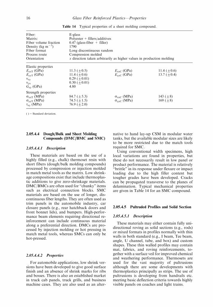
Using conventional width specimens, highlocal variations are found in properties, butthese do not necessarily result in low panel orproduct performance. The material is relativelyªbrittleº in its response under flexure or impactloading due to the high filler content buttougher grades have been developed. Crackscan be propagated transverse to the planes ofdelamination. Typical mechanical propertiesare given in Table 14 for an SMC compound.
2.05.4.5 Pultruded Profiles and Solid Section
2.05.4.5.1 Description
These materials may either contain fully uni-directional roving as solid sections (e.g., rods)or mixed formats in profiles normally with thinwalls in both standard (e.g., I beam, Tee beam,angle, U channel, tube, and box) and customshapes. These thin walled profiles may containmat, fabrics, and roving reinforcements, to-gether with a surface veil for improved chemicaland weathering performance. Thermosets areused for the vast majority of pultrusionsalthough there are some developments withthermoplastics principally as strips. The use ofpultrusions is developing from handrails etc.meeting basic deflection criteria towards highlyvisible panels on coaches and light trains.
Table 14 Typical properties of a sheet molding compound.
Fiber: E-glassMatrix: Polyester+ fillers/additivesFiber volume fraction 0.47 (glass-fiber + filler)Density (kg m73) 1790Fiber format Long discontinuous randomProcess route Compression moldedOrientation x direction taken arbitrarily as higher values in production molding
Elastic propertiesExxT (GPa) 11.3 (+0.5) ExxC (GPa) 11.4 (+0.6)EyyT (GPa) 11.4 (+0.6) EyyC (GPa) 13.7 (+0.4)nxy 0.29 (+0.01)nyx 0.30 (+0.01)Gxy (GPa) 4.80
Strength propertiessxxT (MPa) 84.7 (+5.3) sxxC (MPa) 143 (+8)syyT (MPa) 74.5 (+1.5) syyC (MPa) 169 (+8)txy (MPa) 76.9 (+2.0)
( )=Standard deviation.
Glass Fiber Reinforced PlasticsÐProperties16
2.05.4.5.2 Properties
The properties of the solid rods and squaresections are extremely anisotropic as they arenormally based on aligned rovings with sometransverse reinforcement due to the style of theroving. These rods are most suitable for use astie-rods under tension loads.
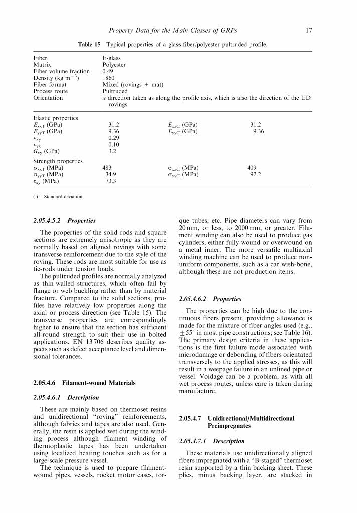
The pultruded profiles are normally analyzedas thin-walled structures, which often fail byflange or web buckling rather than by materialfracture. Compared to the solid sections, pro-files have relatively low properties along theaxial or process direction (see Table 15). Thetransverse properties are correspondinglyhigher to ensure that the section has sufficientall-round strength to suit their use in boltedapplications. EN 13 706 describes quality as-pects such as defect acceptance level and dimen-sional tolerances.
2.05.4.6 Filament-wound Materials
2.05.4.6.1 Description
These are mainly based on thermoset resinsand unidirectional ªrovingº reinforcements,although fabrics and tapes are also used. Gen-erally, the resin is applied wet during the wind-ing process although filament winding ofthermoplastic tapes has been undertakenusing localized heating touches such as for alarge-scale pressure vessel.
The technique is used to prepare filament-wound pipes, vessels, rocket motor cases, tor-
que tubes, etc. Pipe diameters can vary from20mm, or less, to 2000mm, or greater. Fila-ment winding can also be used to produce gascylinders, either fully wound or overwound ona metal inner. The more versatile multiaxialwinding machine can be used to produce non-uniform components, such as a car wish-bone,although these are not production items.
2.05.4.6.2 Properties
The properties can be high due to the con-tinuous fibers present, providing allowance ismade for the mixture of fiber angles used (e.g.,+558 in most pipe constructions; see Table 16).The primary design criteria in these applica-tions is the first failure mode associated withmicrodamage or debonding of fibers orientatedtransversely to the applied stresses, as this willresult in a weepage failure in an unlined pipe orvessel. Voidage can be a problem, as with allwet process routes, unless care is taken duringmanufacture.
2.05.4.7 Unidirectional/MultidirectionalPreimpregnates
2.05.4.7.1 Description
These materials use unidirectionally alignedfibers impregnated with a ªB-stagedº thermosetresin supported by a thin backing sheet. Theseplies, minus backing layer, are stacked in
Table 15 Typical properties of a glass-fiber/polyester pultruded profile.
Fiber: E-glassMatrix: PolyesterFiber volume fraction 0.49Density (kg m73) 1860Fiber format Mixed (rovings + mat)Process route PultrudedOrientation x direction taken as along the profile axis, which is also the direction of the UD
rovings
Elastic propertiesExxT (GPa) 31.2 ExxC (GPa) 31.2EyyT (GPa) 9.36 EyyC (GPa) 9.36nxy 0.29nyx 0.10Gxy (GPa) 3.2
Strength propertiessxxT (MPa) 483 sxxC (MPa) 409syyT (MPa) 34.9 syyC (MPa) 92.2txy (MPa) 73.3
( )=Standard deviation.
Property Data for the Main Classes of GRPs 17

required orientations prior to consolidationand cured at an elevated temperature. The ma-terials have traditionally used autoclaves forconsolidating under pressure at temperaturesup to 120 8C for higher performance applica-tions. However, vacuum or hydraulic pressurecan also be used together with low temperaturecure systems to reduce costs. Alternatively, in-creasing interest is being shown in the use ofresin transfer molding (RTM) using resin im-pregnation into a dry preform and resin filminfiltration (RFI), whereby dry fabric is inter-leaved with resin film so that impregnation andcure occur sequentially during the same processcycle. The thermoset resins used would nor-mally be an epoxy resin although commoditypolymers (e.g., polypropylene) are also beingmarketed and used.
2.05.4.7.2 Properties
When the fibers are laid only in the 08 direc-tion these materials have the highest anisotropyboth in-plane and through-the-thickness. Theuse of lay-ups with other angles in addition to08 decreases the anisotropy in-plane, with littleeffect on through-thickness properties. Forsome cases requiring higher through-thicknessproperties, there is interest in stitching, pinning,and stapling through the thickness, which ismost easily accomplished using the resin trans-fer process.
On loading composites with off-axis (i.e.,nonzero) layers, failure occurs in the ply withthe lowest failure strain (i.e., the 908 layer, that
is equivalent to the weepage strain discussedpreviously), followed by failure of the nexthighest fiber angle layer. Although there isnominally complete freedom in the choice offiber angles, practical reasons drive the designerto standardize on a restricted number of angles(e.g., 08, +458, 908). These practical considera-tions include avoidance of confusion and wastefor hand cutting and lay-up based on preim-pregnate 5600mm wide and standardizationespecially for NCF preforms on a +458 com-ponent of the stitched preform for ensuringadequate shear and bolted joint performance.The standard structural tests of compressionafter impact, pin-bearing, open/filled hole com-pression, and open-hole tension all use quasi-isotropic lay-ups. The above ªstandardº anglesprovide the designer with a reasonable degreeof flexibility. Use of an automatic tape lay-upmachine would encourage the use of other andmore angles to optimize the materials ªdesignºas well as overcoming the above handling lim-itations.
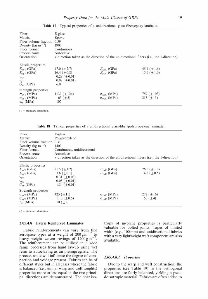
These GRP materials have high in-planestrengths depending on the fiber lay-ups, butlow through-the-thickness properties, even forstitched material. Consequently, it is difficult topropagate a crack transverse to the plies, buteasy to propagate a crack in the plane of thelaminations, which has given rise to Mode I(double cantilevered beam ISO 15 024) andMode II (four-point end notched flexure) meth-ods for interlaminar fracture energies. Typicalmechanical properties are given in Tables 17and 18 for an epoxy and polypropylene matrix,respectively.
Table 16 Typical properties of a filament wound/epoxy material.
Fiber: E-glassMatrix: EpoxyFiber volume fraction 0.60Density (kg m73) 1900Fiber format ContinuousProcess route Filament woundOrientation x direction taken as the longitudinal axis of the cylinder
Elastic propertiesExxT (GPa) 11.2EyyT (GPa) 18.3nxy 0.43nyx 0.71Gxy (GPa) 10.8
Strength propertiessxxT (MPa) 80syyT (MPa) 230txy (MPa) 190
( )=Standard deviation.
Glass Fiber Reinforced PlasticsÐProperties18
2.05.4.8 Fabric Reinforced Laminates
Fabric reinforcements can vary from fineaerospace types at a weight of 200 gm72 toheavy weight woven rovings of 1200 gm72.The reinforcement can be utilized in a widerange processes from hand lay-up using wetresin to autoclaving as an preimpregnate. Theprocess route will influence the degree of com-paction and voidage present. Fabrics can be ofdifferent styles but in all cases where the fabricis balanced (i.e., similar warp and weft weights)properties more or less equal in the two princi-pal directions are demonstrated. The near iso-
tropy of in-plane properties is particularlyvaluable for bolted joints. Tapes of limitedwidth (e.g., 100mm) and unidirectional fabricswith a very lightweight weft component are alsoavailable.
2.05.4.8.1 Properties
Due to the warp and weft construction, theproperties (see Table 19) in the orthogonaldirections are fairly balanced, yielding a pseu-doisotropic material. Fabrics are often added to
Table 17 Typical properties of a unidirectional glass-fiber/epoxy laminate.
Fiber: E-glassMatrix: EpoxyFiber volume fraction 0.59Density (kg m73) 1900Fiber format ContinuousProcess route AutoclaveOrientation x direction taken as the direction of the unidirectional fibers (i.e., the 1-direction)
Elastic propertiesExxT (GPa) 47.0 (+2.7) ExxC (GPa) 45.4 (+1.6)EyyT (GPa) 16.4 (+0.8) EyyC (GPa) 15.9 (+1.0)nxy 0.28 (+0.01)nyx 0.08 (+0.01)Gxy (GPa) 6.0
Strength propertiessxxT (MPa) 1139 (+124) sxxC (MPa) 759 (+103)syyT (MPa) 63 (+5) syyC (MPa) 213 (+13)txy (MPa) 107
( )=Standard deviation.
Table 18 Typical properties of a unidirectional glass-fiber/polypropylene laminate.
Fiber: E-glassMatrix: PolypropyleneFiber volume fraction 0.31Density (kg m73) 1400Fiber format Continuous, unidirectionalProcess route AutoclaveOrientation x direction taken as the direction of the unidirectional fibers (i.e., the 1-direction)
Elastic propertiesExxT (GPa) 21.5 (+1.2) ExxC (GPa) 26.5 (+1.0)EyyT (GPa) 3.6 (+0.1) EyyC (GPa) 4.3 (+0.5)nxy 0.31 (+0.03)nyx 0.05 (+0.01)Gxy (GPa) 1.34 (+0.01)
Strength propertiessxxT (MPa) 425 (+11) sxxC (MPa) 272 (+16)syyT (MPa) 11.0 (+0.5) syyC (MPa) 53 (+4)txy (MPa) 50 (+2)
( )=Standard deviation.
Property Data for the Main Classes of GRPs 19
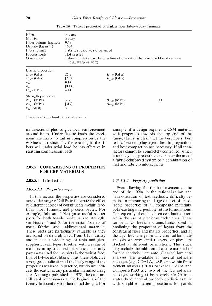
unidirectional plies to give local reinforcementaround holes. Under flexure loads the speci-mens are likely to fail in compression as thewaviness introduced by the weaving in the fi-bers will under axial load be less effective inresisting compression loads.
2.05.5 COMPARISONS OF PROPERTIESFOR GRP MATERIALS
2.05.5.1 Introduction
2.05.5.1.1 Property ranges
In this section the properties are consideredacross the range of GRPs to illustrate the effectof different choices of constituents, weight frac-tions, fiber formats, and process routes. Forexample, Johnson (1984) gave useful scatterplots for both tensile modulus and strength,see Figures 4 and 5, for the major formats ofmats, fabrics, and unidirectional materials.These plots are particularly valuable as theyare based on data obtained from UK industryand include a wide range of resin and glasssuppliers, resin types, together with a range ofmanufacturing and test personnel; the onlyparameter used for the plots is the weight frac-tion of E-type glass fibers. Thus, these plots givea very good indication of the likely range of theproperties achieved in practice, but do not indi-cate the scatter at any particular manufacturingsite. Although published in 1978, the data arestill used by designers at the beginning of thetwenty-first century for their initial designs. For
example, if a design requires a CSM materialwith properties towards the top end of therange, then it is clear that the best fibers, bestresins, best coupling agent, best impregnation,and best compaction are necessary. If all thesefactors cannot be completely controlled, whichis unlikely, it is preferable to consider the use ofa fabric-reinforced system or a combination ofmat and fabric reinforcements.
2.05.5.1.2 Property prediction
Even allowing for the improvement at theend of the 1990s in the rationalization andharmonization of test methods, difficulty re-mains in measuring the large dataset of aniso-tropic properties of all composite materials,both existing and possible future formulations.Consequently, there has been continuing inter-est in the use of predictive techniques. Thesecan be at two levels: micromechanics based onpredicting the properties of layers from theconstituent fiber and matrix properties; and atthe layer level using normally classical laminateanalysis whereby similar layers, or plies, arestacked at different orientations. This stackmay include the addition of a core material toform a sandwich laminate. Classical laminateanalyses are available in several softwarepackages (e.g., COALA, LAP) and within finiteelement analysis (FEA) packages. CoDA andCompositePRO are two of the few softwarepackages working at both levels. CoDA inte-grates these material property predictions fullywith simplified design procedures for panels
Table 19 Typical properties of a glass-fiber fabric/epoxy laminate.
Fiber: E-glassMatrix: EpoxyFiber volume fraction 0.48Density (kg m73) 1600Fiber format Fabric, square weave balancedProcess route Hot pressedOrientation x direction taken as the direction of one set of the principle fiber directions
(e.g., warp or weft).
Elastic propertiesExxT (GPa) 25.2 ExxC (GPa)EyyT (GPa) [25.2] EyyC (GPa)nxy 0.14nyx [0.14]Gxy (GPa) 4.41
Strength propertiessxxT (MPa) 317 sxxC (MPa) 303syyT (MPa) [317] syyC (MPa)txy (MPa) 57
[ ] = assumed values based on material symmetry.
Glass Fiber Reinforced PlasticsÐProperties20

and beams structures, and has been extensivelyvalidated (Sims and Broughton, 1999). In thefollowing discussion some of these predictionsare shown. More detailed treatments are givenin several chapters of Volume 1.
It should also be noted that although theproperties of GRPs are frequently quoted andpredicted according to the volume fraction orvolume percentage of fibers present in the com-posite, the actual production of GRPs is oftencontrolled by using a known weight of reinfor-cement. The resin weighed out will be used toachieve full wet-out of the mat by the operator.The range of weight/volume fractions achievedvaries with the type of fiber format, and to alesser degree the fabrication route, as it affectsthe degree of compaction obtained. Frequently,the composition will be referenced as a resin:fi-ber ratio based on the weights of each compo-nent (e.g., 3:1). This approach accords with theuse of ªunit propertiesº (i.e., load/unit widthper weight of glass fiber/unit area) in the designof GRP pressure vessels as in EN13 121, wherethe load is considered to be carried by theweight of glass fiber present.
The ratio between fiber volume fraction (Vf)and weight fraction (Wf) is given by:
Wf= (Vf6rf)/{(Vf6rf)+ (Vm6rm)} (1)
Vf= (Wf/rf)/{(Wf/rf)+ (Wm/rm)} (2)
where rf= fiber density, rm=matrix density,Vm is matrix volume fraction, and Wm=ma-trix weight fraction. This relationship is plottedin Figure 6. The weight fractions expected aregiven in some product specification standards.For example, in EN13 121 for GRP pressurevessels, the following data are given:
Weightfraction
Volumefraction
Chopped strand mat(CSM) laminates
0.25±0.45 0.09±0.27
Woven roving (WR)laminates
0.45±0.55 0.27±0.36
Filament wound (FR)laminates
0.60±0.75 0.41±0.58
Figure 4 Typical tensile strength for three main types of GRPs.
Comparisons of Properties for GRP Materials 21

Figure 5 Typical Young's modulus for three main types of GRPs.
Figure 6 Plot of relationship between Vf and Wf for assumed densities of 2560 kgm73 and 1200 kgm73 forfiber and resin, respectively.
Glass Fiber Reinforced PlasticsÐProperties22

Associated with these ranges are default unitproperties, which for the CSM are:
Ultimate tensile unit strength=200Nmm71 per kgm72
Ultimate tensile unit modulus
=14 000Nmm71 per kgm72
Equations (3) and (4) are given in the standardto provide a further predictive route to thosediscussed previously. These equations particu-larly reflect the practical industry approach butincreasing computing capability is already mak-ing more complex procedures readily availableto the engineer, as illustrated by the CoDA PCsoftware. The unit properties are given by (unitsare Nmm71 per kgm72 glass-fiber)
Unit tensile ultimate strength for a woven roving in
the warp direction=5006x (3)
Unit modulus for a woven roving in the warpdirection=4000+24 0006x (4)
where x=ratio of glass fiber in warp directionas a proportion of the total glass fiber present.
2.05.5.2 Short-term Properties
2.05.5.2.1 Tension/compression modulus
Most design procedures whether simple orsophisticated will be based initially on stiffnessdata and will often for composite applicationsrelate to strain or deflection limit design. Con-sequently, Young's modulus values are nor-mally required for the principal in-plane
directions using orthogonal axes. The Young'smodulus is important in its own right as itcontrols the displacement/deflection, and thusthe strain in the material. In addition, as manyapplications of composites are based on thin-walled structures (e.g., pultruded profiles, skinsof sandwich structures), the Young's modulusis also important in controlling the ultimateload for the commonly observed, buckling fail-ures. For example, the Euler buckling load isgiven by
P=b (p2EI/L2) (5)
where b varies with the end conditions assumed(e.g., free, pin or fixed), L=column length,I=moment of inertia, and E=Young's mod-ulus.
In Figure 7 are given plots of the predictedtensile modulus for swirled mat and unidirec-tional (both longitudinal and transverse)materials, as representing extremes of fiberformat for continuous fibers. It is clear thatthe in-plane anisotropy varies with fibervolume fraction for the unidirectionally rein-forced materials. For realistic fiber contents(i.e., 50±70%), the ratio of longitudinal totransverse moduli is at a maximum valueequal to *4. The anisotropy will be greaterin CFRPs as carbon fibers have higher axialstiffness and lower transverse stiffness. CFRPswould typically have longitudinal and trans-verse moduli of 140±200GPa and 10GPa,respectively.
Indicative values of the tensile modulus forseveral classes of composite materials are com-pared in Figure 8. It is noticeable that several ofthe ªvolumeº compounds (e.g., GMT, SMC,CSM) have little or no anisotropy. These values
Figure 7 Tensile elastic modulus as a function of fiber content for continuous mat and unidirectionalGRPs.
Comparisons of Properties for GRP Materials 23

for the GRP material should be compared withan aluminum alloy and steel values of 70GPaand 210GPa, respectively, highlighting againthe importance for their competitiveness ofthe low density of GRPs/PMCs. CFRPswould have values of the order 10GPa and150±200GPa for the transverse and longitudi-nal directions, respectively.
The compression modulus is normally as-sumed to be equal to the tension in both simpledesign analysis and FEA. Differences have beenreported between tension and compression va-lues, but the user should exercise care in usingthe data until it has been fully validated. Forexample, the tension tests use a gauge length of550mm, whereas the compression tests usestrain gauges 3mm long strain gauges togetherwith the attendant difficulties of compressiontesting.
2.05.5.2.2 Shear modulus
For an isotropic material the relationshipbetween the stiffness parameters Young's mod-ulus (E) and shear modulus (G) is given by
G=E/2(1+ n) (6)
whereas for an anisotropic material, the equiva-lent equation for the in-plane shear modulusG12 is
G12
Gm� �1� xZVf��1ÿ ZVf� �7�
where
Z � �G12f=Gm� ÿ 1
�G12f=Gm� � x0�8�
and the reinforcement constant x is equal to 1.This leads to different absolute values, and
different values for the ratios of the in-planeshear to in-plane tension. For unidirectionalmaterials the in-plane shear values are close tothe through-thickness shear modulus. It is im-portant that the differences between the isotro-pic case and the anisotropic are recognized, as itcan have a substantial effect on the deformationof beams in flexure if the load is offset, or forbuckling problems such as torsional buckling ofGRP lighting columns.
In Figure 9 are graphs of the predicted in-plane shear modulus for mat, cross-ply, andunidirectional materials. Several GRPmaterialsare compared in Figure 10. These shear valuescan be increased by preferential alignment at458 to the principal axis, which is successfullyemployed for filament-wound torque tubesused for power transmission applications.
2.05.5.2.3 Poisson's ratio
In common with the shear modulus valuesfor GRPs, the Poisson's ratio values are alsoanisotropic and can be very different than forthe isotropic material case, so that they need tobe known, measured, or predicted. The depen-dencies on volume fraction for continuous fibermat and unidirectional materials (nb. axial in-plane value, n12) are shown in Figure 11. Formetals a value of 0.3 is often assumed to theextent that it is included in a design equation asa constant.
The range of values for several GRPs areshown in Figure 12. The end point of eachdata bar are the axial and transverse Poisson'sratios. Lay-ups of the +y8 variety can givevalues greater than the 0.5 value obtained for
Figure 8 Typical values of the tensile elastic modulus, GPa (gray bars= range, white bars=0 and 908values).
Glass Fiber Reinforced PlasticsÐProperties24

Figure 9 In-plane shear modulus as a function of fiber content for a continuous mat and unidirectionalGRP.
Figure 10 Typical values of in-plane shear modulus, GPa (nb. CFRP for comparison).
Figure 11 Major Poisson's ratio as a function of fiber content for continuous glass fiber-reinforced epoxylaminates.
Comparisons of Properties for GRP Materials 25

rubbers that is taken as the normal limit,although the values are lower for GRP systemsthan for CFRP systems.
2.05.5.2.4 Axial strength
GRPs are essentially elastic to failure,although depending on the fiber format anddirection relative to the loading axes, therewill be in some cases degrees of viscoelasticbehavior for resin-dominated properties (e.g.,shear). In many materials, deviation from alinear curve occurs as the load is increaseddue to different modes of microdamage, princi-pally associated with reinforcement at 908 tothe applied load direction and the associatedstrain concentrations. These damage modes in-clude debonding leading to microcrackingwithin fiber bundles and matrix cracking inresin-rich regions. The effect is most pro-nounced in 08/908 cross-ply systems loadedalong one of the principal fiber directions, ascracks can form along the full width and thick-ness of the layer.
The damage occurring gives rise to a loss instiffness in the system, which can appear as aªkneeº in the curve. The damaged material stillresponds in a linear manner but with a lowerstiffness. The knee would be a sharp transitionif for a 08/908 cross-ply all the transverse fail-ures occurred in the 908 ply at a single failurestrain. In actual materials the microcracksoccur over a range of strain giving rise to asmooth transition at the knee, as shown inFigure 13. However, this behavior is not aform of plasticity or ductility, as related toyield behavior. The damage gives rise to lowerdynamic moduli and higher damping values.
The design strains used for long-term loadsreflect this microdamage as the relevant failurecriteria where, for example, it allows weepage ofthe contained fluid in a process pipe or chemicalprocess vessel. The standard EN13 121 pro-poses a maximum design strain of 0.25% forlong-term service, with limited excursions to0.4% for limited upset or overload conditions.These values are well below the ultimate failurestrains for 08 unidirectional layers of >1.5%.
In Figure 14 are given several stress±straincurves for different classes of GRP (Echter-meyer et al., 1996). From these curves it ispossible to see the wide range of responsesobtained in terms of initial modulus (i.e., stiff-ness), ultimate strength (s), degree of nonli-nearity, energy or work to failure (i.e., areaunder the curve), and failure strain throughusing different fiber formats.
The anisotropy in aligned systems is higherfor the strength properties than for modulus.Unless the load is applied solely in the 08 direc-tion, it is clear that a multidirectional lay-up isrequired to take care of the off-axis loads, eventhough they may be of a secondary magnitude.Failure of well-prepared and well-made bonded
Figure 12 Typical values of axial and transverse Poisson's ratio (gray bars= range, white bars=0 and 908values).
Figure 13 A typical tensile stress±strain curve for a08/908 system.
Glass Fiber Reinforced PlasticsÐProperties26

joints with thin adherends will occur in thecomposite along the weaker interlaminar inter-faces in the composite rather than in the adhe-sives or interface. Many tests methods aimed atproviding more structural information thanplain coupons on the effect of stress concentra-tions (e.g., open hole tension, open/filled holecompression, pin-bearing strength) use speci-mens cut from quasi-isotropic material basedon unidirectional fiber plies laid up at 08, 908,and +458 angles. In Figure 15 are showngraphs of the predicted tensile strength for theextremes of continuous fiber mat and unidirec-tional materials (08 and 908). The tensilestrengths of several GRP materials are com-pared in Figure 16.
The compressive strength of GRPs, as for allcomposites, is difficult to measure uniquely. Asmost composites are in thin sheet form, under acompressive load it is important that the mate-
rial does not failure under simple Euler buck-ling conditions (see Equation (5)). Normally, ashort gauge length specimen is used to avoidthis failure mode, but failure can then occur bylocal buckling, including crippling or micro-buckling failures. It is also important that fail-ures do not occur through bearing failures atthe end of the specimen under end-loaded con-ditions. It is agreed that although many differ-ent loading jigs are available, there remainsdoubt regarding the measured data as theopportunity exists to load nonaxially throughpoor test machine/loading jig alignment andpoor specimen preparation giving unsymmetri-cal specimens. The new harmonized standards,EN ISO 14,126 and ASTM D 3410, include therequirement to measure the back-to-backsurface strains to ensure that the specimen isaxially loaded. It is hoped that these methodswill lead in the future to more confidence in
600
500
400
300
200
100
00 0.5 1.0 1.5 2.0 2.5 3.0
Strain (%)
Str
ess
(MP
a)
0° unidirectional
0/90 cross-ply
Mat + rovings
Stiched mat + rovings
CSM
90° unidirectional± 45° angled-ply
Figure 14 Typical tensile stress±strain curves for a different GRPs (after Echtermeyer et al., 1996).
Figure 15 Tensile strength as a function of fiber content for continuous mat and unidirectional GRP.
Comparisons of Properties for GRP Materials 27

measured compressive strength values and re-duced costs through the elimination of the needfor suppliers to meet a range of compressiontests for different customers. These difficultiesdo not occur to the same degree for the lessanisotropic molding compounds, which fail atlower loads. In Figure 17 are given indicativevalues for the compression strength of severalGRPs.
2.05.5.2.5 Shear strength
The shear strength (t) is one of the moredifficult properties to measure and several com-peting methods are available that need to beselected on a case by case approach as not allnominally shear testing modes give shear fail-ures. Broughton et al. (1996) reviewed availabletest methods as part of a research program on
measuring the properties in all three shearplanes. It was noted that for several testmodes and/or materials, failure was initiatedin compression or tension rather than by thedesired shear mode. The typical values for dif-ferent GRPs shown in Figure 18 illustrate thesmall range of values normally obtained. Fortorque tube designs fibers would be orientatedat +458 to the tube axis to give higher shearproperties, both stiffness and strength.
2.05.5.2.6 Through-thickness properties
As thick composites are of increasing interestand the design of thin membranes becomesmore accurate, a full three-dimensional data-base including through-thickness (T-T) proper-ties is required. Thick in this context probablymeans greater than 10mm, which is the limit for
Figure 16 Typical values of tensile strength, MPa (gray bars= range, white bars=0 and 908 values).
Figure 17 Typical values of compressive strength, MPa (gray bars= range, white bars=0 and 908 values).
Glass Fiber Reinforced PlasticsÐProperties28

many in-plane test methods. However, there arecases where the data are required for the con-ventional 2±5mm thicknesses. For example, inlap joints of ªthinº material, failure of a cor-rectly designed and manufactured joint will befrequently in the composite itself.
There are difficulties with the measuring theT-T data due to the availability of the materialand the subsequent testing difficulties, particu-larly in tension. Material is not normally avail-able to allow the standard 250mm long
coupons to be prepared. Consequently, tensionand compression specimens have been designedthat require only 10±20mm thick material. Atthese thicknesses there is less concern for afurther artefact, namely that the material is ata larger thickness than in the application so thatthe cure, the voidage, volume fraction, residualstresses, etc. may be different.
Data obtained during a recent test methoddevelopment program are shown in Tables 20and 21 (Lodeiro et al., 1999). Some caution
Figure 18 Typical shear strength values, GPa.
Table 20 Through-thickness tensile (T) and compressive (C) properties.
Material Mode E33 (GPa) n31 n32 s33 (MPa)
CSM T 6.3 0.25 (+0.05) 0.21 (+0.05) 9.1 (+2.0)C 6.2 (+0.3) 0.23 (+0.04) 0.23 (+0.04) 202 (+12)
Fabric/epoxy T 10.2 (+0.2) 0.17 (+0.01) 0.16 (+0.01) 61 (+5)C 10.7 (+0.4) 0.17 (+0.01) 0.19 (+0.01) 509 (+22)
Disc. Inject. T 4.4 (+0.1) 0.27 (+0.04) 0.41 (+0.02) 69 (+2)Thermoplastic C 4.2 (+0.1) 0.21 0.44 195 (+5)GMT T 3.5 (+0.2) 0.16 (+0.04) [0.16 (+0.04)] 5.7 (+1.6)
C 3.3 (+0.4) 0.27 [0.27] 210 (+9)
( ) standard deviation. [ ]=assumed values based on material symmetry assumptions.
Table 21 Through-thickness shear properties.
Material Gxz (GPa) Gyz (GPa) txz (MPa) tyz (MPa)
CSM 1.64 (+0.09) [1.64 (+0.09)] 40.7 (+1.7) [40.7 (+1.7)]26 2 TwillFabric/epoxy
4.12 (+0.14) [4.12 (+0.14)] 68.4 (+0.9) 68.4 (+0.9)
Discont. Inject.Thermoplastic
1.68 (+0.06) 56.9 (+3.6) [56.9 (+3.6)]
GMT 1.04 (+0.2) [1.04 (+0.04)] 22.7 (+0.8) [22.7 (+0.8)]
[ ] = assumed values based on material symmetry assumptions.
Comparisons of Properties for GRP Materials 29

needs to be applied to the use of the data as thetest methods have not finished their develop-ment and been subjected to an interlaboratoryvalidation.
2.05.5.3 Long-term Strength Properties
2.05.5.3.1 Fatigue
Both glass and carbon unimpregnated fiberbundles exhibit excellent fatigue resistanceunder sinusoidal cyclic loading conditions.For a given tensile stress and comparable fibervolume content, composites composed ofhigher modulus fibers will exhibit superior fa-tigue resistance in the longitudinal direction.The induced strain within the matrix will belower for these systems and as a result the rateof damage accumulation within the matrix andat the interface will be reduced.
The fatigue strain experienced by unidirec-tional GRP laminates generally exceeds thefatigue strain limit of the matrix, whereas themaximum strain experienced by unidirectionalCFRP laminates falls well below this limit, evenat stresses approaching the ultimate tensilestrength of the material. Unidirectional GRPlaminates fail through progressive fatigue da-mage, whereas fatigue damage in equivalentCFRP laminates is suppressed with only staticfailure being possible. R-glass fiber compositeshave higher tensile strength and higher strengthduring fatigue than an equivalent compositereinforced with E-glass fibers, although thenormalized S±N data is almost the same. Lowstiffness carbon fiber composites can be ex-pected to exhibit some progressive fatigue da-mage (reviewed by Wells, 1984).
A simple procedure that has been used torepresent several sets of data is the normaliza-tion of the fatigue data with respect to theultimate strength under identical conditions(Mandell et al., 1981; Harris et al., 1990; Simsand Gladman, 1978). The normalized compo-site fatigue sensitivity was almost identical forfiber volume fractions ranging from 0.15 to 0.50% (reviews by Hancox andMayer, 1984; Wells,1984). It was also found that the normalizedfatigue sensitivity (i.e., fractional loss in tensilestrength per decade) tends to be similar in ten-sion for R(sMIN/sMAX) ratios ranging from 0.0to 0.1, independent of matrix type, interface,void content, filler and fiber content, and fiberformat, length (provided the fibers are longerthan the minimum length to transfer load), anddistribution.
The normalized S±N data can be representedby a linear relationship as follows (Mandellet al., 1981; Sims and Gladman, 1978, 1980):
sMAX/sUTS=17 klog10N (9)
where sMAX is the maximum applied load,sUTS is the ultimate tensile strength, and k isthe fractional loss in tensile strength per decadeof cycles. The value of k is typically 0.08 to 0.1.GRP laminates can sustain loads for at least 106
cycles at stress levels approximately equal to25% of the ultimate tensile strength, measuredat the ªfatigueº loading rate.
As the ultimate tensile strength has beenshown (Sims and Gladman, 1978) to be rate-dependent (see Section 2.05.5.9), it is importantthat the normalization uses the strength mea-sured at a rate equivalent to that used in thefatigue tests. The higher the rate of stress ap-plication (RSA) or frequency, the higher thefatigue strength, however, normalizing theS±N data in terms of the static strength ateach RSA causes the S±N curves to superim-pose (Sims and Gladman, 1978). This depen-dence also has implications when the servicefrequency is much slower than the faster rateused to minimize the time to obtain the labora-tory data. Sims and Gladman (1978) used tri-angular waveforms to set a single uniqueloading rate for both fatigue and ultimatestrength tests. Small differences were onlyfound at low cycles-to-failure between S±Ndata obtained using square, triangular, andsine waveforms.
In Figure 19 data are shown for four glass-fiber/epoxy laminates with a range of ultimatetensile strengths. The data shown have beennormalized as above and are shown to fit wellscatter bands based assuming a constant rate ofdegradation and a width based on the coeffi-cient of variation of 3% measured for the UTS.The wider scatter band more appropriate for aCSM material on the same basis predicts a lifevariation of three decades, as observed, ratherthan less than one decade for the fabric basedsystem.
This rule of thumb applies to a wide range ofglass fiber-reinforced plastics, with and withoutholes or notches. Materials conforming to thisbasic rule include continuous unidirectionaland multidirectional laminates, woven fabrics,and sheet and injected molded compounds. Thetensile fatigue behavior (107 cycles) of mostGRP systems is fiber dominated. The higherthe alignment, the higher the initial tensilestrength and the higher the strength duringfatigue for a given number of cycles.
This relationship has also been reported forseveral injection molded glass-fiber thermoplas-tic systems, and also for similar carbon-fiberreinforced systems. The value of k in Equation(9) was found to range from 0.09 to 0.12. Thesevalues are higher than usually observed but are
Glass Fiber Reinforced PlasticsÐProperties30

probably based on the normal UTS rather thanthe ªfatigueº rate data which would reducethese values.
Glass fiber-reinforced laminates can sustainhigher fatigue loads at low temperatures than athigh temperatures as shown in Figure 20. Thedata was obtained for a glass-fiber/epoxy usedin the electrical industry with negligible voidageand low scatter (i.e., coefficient of variation forthe tensile strength of 3%). The material is idealfor studying the effect of different test para-meters. The low scatter of the tensile strengthtransfers directly to the fatigue response result-ing in less than one decade of scatter at any setstress level. In Section 2.05.2.6 is shown the vari-ation of the tensile strength over the tempera-ture range ±150 8C to 150 8C. The fatigue data inFigure 20 has been normalized with respect tothe tensile strength in Figure 28 at the corre-sponding temperature to give the normalizeddata shown in Figure 21. Although the fatiguedata has a factor of four change in absolutemagnitude, the normalized data falls within a
narrow band (see Figure 21) with the fractionalloss in tensile strength per decade of cycles beingapproximately 0.1 (Sims and Gladman, 1982).
A reduction in the stress amplitude whilstmaintaining the same peak stress extends thefatigue life of a composite laminate. The nor-malized S±N curves become flatter (i.e., reducedrate of degradation) with increasing R ratios for0.014R41.0. Similarly, GRP has an improvedfatigue resistance when subjected flexural load-ing conditions compared to tensile loading.
A major concern when conducting fatiguetesting under compressive loading conditionsis ensuring the test data is valid. Prevention ofEuler buckling through the use of antibucklingdevices can be expected to alter the fatigueperformance and introduce uncertainty regard-ing how themuch load is carried by the jig ratherthan the specimen. Failing to prevent bucklingwill compromise the fatigue performance.
The published data suggests that the fatiguestrength of GRP systems degrade at a similarrate (provided the rate of stress application and
140
120
100
80
60
40
20
010–1 100 101 102 104 105103 106 107
Cycles to failure
Per
cent
ages
of U
TS
(%
)
Mean result
95% confidence limits for C.V. = 3%
95% confidence limits for C.V. = 15%
– UTS = 408 MN/m2
– UTS = 337 MN/m2
– UTS = 365 MN/m2
– UTS = 326 MN/m2
Figure 19 Illustration of predicted scatter bands and measured data for four similar glass-fiber fabric/epoxymaterials.
500
400
300
200
100
10–1 100 101 102 104 105103 106
Cycles to failure
Max
imum
str
ess
(MN
/m2 )
Test temperature (°C)
–150–100
–50
–20+23+60
+100
+150
Figure 20 S±N curves at different test temperatures for a glass-fiber fabric/epoxy.
Comparisons of Properties for GRP Materials 31

R ratio are the same) and that the fatiguestrength (as with the static strength) is depen-dent on the fiber content, fiber format, andmaximum operating temperature of the matrix.
2.05.5.3.2 Creep
The creep resistance of unimpregnated glassfiber strands is relatively poor in comparisonwith carbon fibers, which can sustain loadsapproaching the tensile strength of the carbonfiber bundle for an indefinite period of time ineither air or water. The stiffer the fiber reinfor-cement the smaller the creep strain, hence car-bon fiber composites have lower creep ratesthan their equivalent GRP counterparts. Re-duction in creep modulus (or stiffness) withtime is greater for GRP. The creep performanceappears to be comparable between differentmatrix materials (i.e., polyester, epoxy, or phe-nolic resins). Differences can be expected fortests at elevated temperatures or with exposureto aggressive environments. The relative creepperformance will be dependent on the resis-tance of the matrix to environmental factors.Matrix softening occurs at elevated tempera-tures (i.e., above Tg) causes a substantial in-crease in the deformation of the systemresulting in large and unusble deformations.
The most creep resistant combination iswhen continuous aligned materials are loaded
in tension parallel to the fibers with off-axisloads encountering less resistance from thecomposite. Off-axis tensile tests have shownthat the creep behavior for 458 and 908 lami-nates are nearly identical, and very similar tothe creep behavior of the matrix (Scott et al.,1995). Creep resistance is also lower undercompressive and shear loads. Cross-ply (i.e.,08/908) nonwoven laminates are relativelycreep resistant to tensile loads, whereas thewoven counterparts are more susceptible tocreep as fiber straightening contributes to over-all deformation. Random fiber arrays (e.g.,CSM) are the least resistant to creep. Thecreep performance of unidirectional pultrudedGRP is comparable with steel, but significantlyworse than for CFRP. The rupture times atequivalent stress levels are several orders ofmagnitude greater for CFRPs compared withthose for GRP. Aramid composites have creeprates orders of magnitude higher than GRPs. InFigure 22 is shown creep rupture data obtainedfor CSM in distilled water.
2.05.5.4 Moisture, Water, Marine, andWeathering Resistance
2.05.5.4.1 Moisture and water effects
GRPs are used in many applications whereexposure to moisture or immersion in water is a
100
80
60
40
20
010–1 100 101 102 104 105103 106 107
Cycles to failures
Per
cent
age
of U
TS
(%
) Test temperature (°C)1501006023
–20–60–100–150
= run out
Figure 21 Normalized fatigue S±N fatigue curve for a glass-fiber fabric/epoxy.
1000
100
10Max
imum
str
ess
(MN
/m–2
)
102 103 104 106 107105 108
Time (s)
Year
Figure 22 Creep rupture data for CSM in distilled water.
Glass Fiber Reinforced PlasticsÐProperties32

major requirement. This may be as part of thegeneral atmosphere, as for, for wind-turbinesand building cladding panels, when other as-pects of ªweatheringº such as UV exposureneed to be considered. Other applications thatinvolve full immersion, with moisture also pre-sent, include pleasure and work boats, mine-sweepers, water piping, and potable watertanks. GRP laminates can absorb relativelysmall (typically 0.3±1.5%) but potentially da-maging amounts of water from the surroundingenvironment. Consequently, care should betaken to optimize the specification and manu-facture of the GRP material to meet theseneeds.
The moisture absorption kinetics of polymersystems differ widely and also change withphysical aging. Although the process of moist-ure absorption and desorption from the surfacelayers occurs immediately on contact with theenvironment, moisture flow into or out of theinterior of composite structures will be slow. Itmay take weeks or months of exposure tohumid environments before a significantamount of water is absorbed by the composite.This particularly applies to GRPs with a thick-ness of greater than 10mm. The amount ofmoisture absorbed by GRP laminates is depen-dent on matrix, temperature, exposure time,and mechanical loading conditions. The rateof moisture uptake and hence degradation isaccelerated under tensile loads.
Absorbed water may produce a number ofadverse effects: (i) dimensional changes (swel-ling); (ii) reduction in the glass transition tem-perature Tg of the matrix; (iii) reduction of themechanical properties of the matrix and thefiber±matrix interface; and (iv) chemical degra-dation of the glass fibers. Moisture inducedeffects are often reversible on drying the com-posite (nb. measurement of Tg discussed inSection 2.05.3). In addition, absorbed moisture
will modify the changes in internal stresses.Composite properties dominated by matrixcharacteristics (e.g., transverse tension, long-itudinal compression, and shear) are particu-larly susceptible. It is therefore essential that aresin-rich layer is present on the composite sur-face to protect the glass fibers from moisturedegradation. This is usually accomplished bythe use of gel coats and surface veils.
For example, the Tg, as an indicator of themaximum service or operating temperature, ofpolyester resins is sensitive to absorbed moist-ure. Figure 23 shows the influence of moisturecontent on Tg for a typical polyester. The Tg isreduced by approximately 15±20 8C for a 2%moisture weight gain, where the effect is notdependent on the conditions used for waterconditioning. However, the rate of moistureuptake and reduction in operating temperatureis temperature dependent. The higher the tem-perature the more rapid the degradation pro-cess. At temperatures approaching the Tg of theresin, there can be loss of organic materials(e.g., additives) through leaching. Fick's lawwill no longer apply in this case. GRP productstandards (e.g., Lloyd's Rules, EN 13 121)require that the operating temperature shouldbe 30±40 8C below the Tg or DTUL tempera-ture, so that these conditions should not occurin service unless initial water absorptionreduces the Tg to the sensitive area or highertemperatures are used as a method of accelerat-ing the testing for material properties.
The influence of the absorbed moisture onthe transverse and longitudinal flexuralstrength of a continuous aligned glass fiber-reinforced laminate is shown in Figures 24and 25. The effect of increasing moisture is toreduce the maximum strength of the materialand reduce the maximum operating tempera-ture. The plots show that longitudinal strengthis less sensitive to changes in moisture content.
Figure 23 Glass transition temperature for a moisture conditioned polyester resin.
Comparisons of Properties for GRP Materials 33

At room temperature, the transverse flexuralstrength retention is only 50% compared withthe strength of the dry material, and fallsfurther as a percentage change at higher tem-peratures. Figure 26 compares the deleteriouseffects of moisture on the transverse flexuralstrength of aligned glass and carbon fiber-rein-forced epoxy laminates dry and wet (approxi-mately 1wt.% moisture) at room temperature(23 8C) and 100 8C. The CFRP laminate isaffected to a far lesser degree than the GRPlaminate.
2.05.5.4.2 Weathering and marineenvironments
GRP laminates generally have good weath-ering properties, although there is limited reallife data published for comparative purposes on
strength retention or lifing of these materialsunder natural weathering conditions. Weath-ering encompasses the combined effect oftemperature, moisture, and sunlight (i.e., ultra-violet radiation). The combined effect oftenleads to hydrolytic and photo-oxidative degra-dation of the composite. The incorporation ofUV stabilizers in GRP materials prevents thisproblem occurring. An outer gel-coat or pro-tective (e.g., polyurethane) paint will also pro-vide protection for the underlying substrate.
Research (Hale and Gibson, 1998) has shownthat after 4 years exposure in a temperateclimate (UK) or exposure in a marine (salt-water) environment, the strength retention ofCSM/polyester laminates remains relativelyunaffected (typically 95% of UTS). The effectson strength of the GRP materials whenexposed, over the same period, to a tropicalenvironment (Kuala Lumpur, Malaysia) were
Figure 24 Transverse flexural properties of conditioned E-glass/epoxy laminate with temperature.
Figure 25 Longitudinal flexural properties of conditioned E-glass-fiber/epoxy laminate with temperature.
Glass Fiber Reinforced PlasticsÐProperties34

far more severe. The strength retention was81% after 4 years exposure. The quality of thegel-coat is important to ensure a reliable barrierto moisture ingress and preventing blister for-mation and osmosis, particularly for use inmarine environments.
Exposure to salt spray or salt water willdegrade glass fiber-reinforced systems with thedegree of protection depending on the perme-ability of the resin to diffusion of chloride ionsand the ability of the matrix and interface toresist premature cracking, which would allowthe environment to come in direct contact withthe fibers resulting in their corrosion.
The strength and impact strengths of un-stressed polyester and epoxy based GRP lami-nates will steadily decrease when exposed toone of the following environments: distilledwater, simulated sea water, simulated sun-light/salt spray, and actual sea conditions. Aflexural strength reduction of 14±22% over a3±9 month period has been observed (Hale andGibson, 1998). Epoxy-based systems are intrin-sically more resistant to marine environments,undergoing a reduction in flexural strength of10±15% over a 12 month exposure period. Areduction of 50% has been observed over a 6±9month exposure period.
Osmosis causing surface blistering, althoughprimarily cosmetic, is a very common problemthat occurs in laminated structures that havebeen immersed for long periods in aqueoussolutions (e.g., marine applications). The phe-nomenon affects laminates contaminated bywater-soluble impurities. Osmosis was first re-cognized on GRP boats, and to a lesser extentin water tanks and swimming pools, but there isnow knowledge in the GRP industry that al-lows the problem to be avoided providing theguidelines are followed (see BPF Avoiding
Osmosis) regarding the choice of resin, gel-coats, working practice, etc. Improvementsare obtained from using isophthalic ratherthan orthophthalic resins, powder bondedrather than emulsion bonded chopped mat,and properly cured systems.
2.05.5.5 Fiber Degradation
This section deals specifically with the under-lying mechanisms involved in degradation ofthe fibers themselves. As such it forms a primerfor discussion in Sections 2.05.5.4.1, 2.05.5.4.2,and 2.05.5.7 on the effects of water and chemi-cal environments.
The tensile strength of freshly drawn E-glassfibers is typically 3.5GPa. This strength can befully realized, provided the fibers are carefullyhandled to avoid surface damage and are storedin a dry environment. Exposure to humid airwill compromise the load bearing capacity ofthe fibers, resulting in a loss of strength and anincrease in variability in strength. For thesereasons, the variability in the tensile breakingstress and strain for carbon fiber tows is notice-ably less than for E-glass fiber tows.
The loss of tensile strength of E-glass fibers isdependent on exposure time, temperature, andthe degree of humidity. On initial exposure to ahumid/water environment, the rate of fiber de-gradation is relatively rapid, even in benignenvironments, such as air conditioned labora-tories (typically 23 8C and 50% relative humid-ity (RH)). The tensile strength is reduced toapproximately 3.0GPa after 20 days exposurein air at 20 8C and 65% RH. Immersion inwater at the same temperature results for thesame period of time in a 30% strength reduc-tion (i.e., tensile strength of 2.5GPa). Further
Figure 26 Transverse flexural properties of conditioned E-glass-fiber/epoxy and carbon/epoxy laminates atroom temperature and 100 8C.
Comparisons of Properties for GRP Materials 35

strength loss occurs with increasing exposuretime. After 100 days, the strengths in air andwater are 2.6GPa and 2.1GPa, respectively(Ehrenstein et al., 1990). This process is par-tially reversible. Exposure to boiling water in-creases the loss of strength (*75% loss in 24 h).As a result of the degradation that occurs to E-glass fibers, an in situ tensile strength of 2.0GPais often assumed when designing compositelaminates.
The loss in tensile strength of E-glass fibers isassociated with microcrack formation on thesurface and a decrease in the load bearing fiberdiameter by ion exchange with the surroundingmedia. Sizing of the fiber during the productionprocess provides protection, although this islimited against a number of chemical agents.As with moisture effects, acid and alkali degra-dation processes are accelerated at elevatedtemperatures. Compared with other glass fibertypes (e.g., R, ECR, and C), E-glass is particu-larly vulnerable to attack from mineral acids(e.g., HCl and H2SO4) and alkalis (e.g., NaOHand KOH). Dilute mineral acids and alkalis arenot only encountered in the chemical plantindustry, but are also present in industrial ef-fluent and sewage. A comparison of tensilestrengths for different glass fibers before andafter exposure to a 5% H2SO4 at 23 8C(Figure 27) shows ECR- and R-glass fibershaving superior corrosion resistance to sulfuricacid solutions.
Significant improvements in the corrosionresistance of GRP structures to mineral acidsare possible by using ECR-glass fibers. UsingECR-glass fibers in preference to E-glass fiberscan significantly extend the life of GRP lami-nates by one or two orders of magnitude. The
differences in corrosion resistance between thedifferent fiber types to different acids and alka-lis are dependent on the reactivity of the fiberchemistry to the agent. Each particular fiberchemistry bestows a certain resistance againstattack from a range of chemicals, rather thanwholesale protection.
The process of corrosion is accelerated undermechanical loads (i.e., stress corrosion) with thelong-term strength of glass fiber-reinforcedplastics under hostile environments being con-trolled by stress corrosion of the fiber reinfor-cement. Static fatigue or creep rupture, whichrefers to the time-dependent failure of a mate-rial when subjected to a constant load, is usedas a measure of gauging the relative resistanceof a material (i.e., fiber or composite) to che-mical environments. The less resistant the fiberis to a particular environmental condition, themore rapid the drop in the rupture stress timecurve. Figure 27 shows the detrimental effectthat water has on the ability of glass fibers tosustain load.
The normalised stress rupture curves for theE-glass fibers when plotted on a linear-log plotcan be ªapproximatedº by a straight line fit asfollows
sAPP/sUTS=17 klog tf (10)
where sAPP is the applied load (or stress), sUTS
is the maximum short-term strength of the un-conditioned material, k is the slope, and tf is thetime to failure. The more aggressive the envir-onment the larger the constant k. The similarityof this equation to that shown previously,Equation (9), for fatigue is very significant forconfirming the degradation rates.
Figure 27 Stress rupture of E-glass fibers in air and water.
Glass Fiber Reinforced PlasticsÐProperties36

2.05.5.6 Temperature Resistance
The matrix dominated properties such ascompressive, flexural, shear, and transverseproperties are most affected by the temperaturedependence of the matrix. Depending on thefiber format the tension properties are less af-fected. In Figure 28 is shown the dependence ofthe tensile strength for the glass-fiber fabric/epoxy laminate discussed previously over thetemperature range7150 8C to 150 8C. The per-formance of epoxy and phenolic GRP is super-ior to that of vinyl ester, which in turn offersbetter elevated temperature performance thanpolyester.
Oxidation is the primary degradation pro-cess at elevated temperatures with the rate ofdegradation increasing with the amount ofoxygen present. The primary path for oxygendiffusion is through the polymer and alongthe fiber±matrix interface, which can be rela-tively rapid at elevated temperatures. Oxida-tion can result in loss of strength anddiscoloration.
Most GRP materials are generally unim-paired at subzero temperatures and in somecases short-term elastic and strength properties(e.g., polyester-based systems) are enhanced.Exposure to subzero temperatures as low as755 8C generally has no detrimental effect onthe stiffness and strength of continuous unidir-ectional GRP laminates.
The variation in the maximum operatingtemperature for GRP ranges from approxi-mately 90 8C (GMT) to 200 8C (continuousaligned epoxy). The heat resistance of GRPlaminates is less than that for mild steel orstainless steel, but comparable with aluminumalloys. Figure 29 shows typical heat resistancedata for a range of GRP laminates and metals.Mild steel and stainless steel have typical max-imum operating temperatures of 500 8C and
700 8C, respectively, with the heat resistanceof aluminum alloys typically between 150 8Cand 200 8C.
2.05.5.7 Chemical Resistance
Glass fiber-reinforced plastics are normallyresistant to degradation from mild acids, alka-line solutions, and humidity. These materialsdo not ªrustº and are comparatively corrosion-resistant, hence the increasing use of these ma-terials by the chemical and offshore industriesfor storage tanks, reaction vessels, and pipes.Corrosion can occur, however, due to ingress ofthe aggressive media resulting in stress corro-sion cracking, and as a consequence a loss instiffness and strength.
2.05.5.7.1 Chemical and physical agents
The effect of different classes on GRP lami-nates are briefly discussed below. As noted forwater environments, the performance of theGRP is closely linked to the resin matrix per-formance. A full list of chemical agents andtest methods for assessing the effects of chemi-cal exposure are given in ISO 175 and prEN2489.
(i) Acid and alkaline agents, as previouslymentioned, can degrade fiber, resin, and thefiber±matrix interface. The degree of degrada-tion is dependent on concentration levels andtemperature. In general, epoxy resins are moreresistant than polyester, while high-perfor-mance thermoplastics (e.g., polyetherketone)are virtually impervious to ordinary chemicalattack. E-glass fibers are known to suffer stresscorrosion when exposed to acidic solutions(e.g., sulfuric acid).
Figure 28 Plot of ultimate tensile strength as a function of temperature.
Comparisons of Properties for GRP Materials 37

(ii) Hydrolysis by hot water, aqueous alkalis,and acids is a serious problem for polyestersand polyamides. Strong alkalis are particularlyharmful to polyesters, which can be completelydestroyed. These same groups of chemicalreagents can also induce ion exchange reactionsin glass fibers, leading to flaw initiation andpropagation under mechanical load.
(iii) Paint strippers combined with abrasiontechniques can cause irreversible materialdamage. Marine and civil structures may bepainted several times during their service life,and hence care is needed to ensure that thispotentially highly destructive process does notdegrade the esthetic appearance and compro-mise material performance of the composite.
A majority of matrix resins are susceptible tooxidation by any one of numerous oxidizingagents (e.g., hydrogen peroxide and certainbleaches such as hypochlorite, nitric acid, orsulfuric acid). Often, constituents such as fillers,fire retardants, and curing agents are morereactive than the resin or fiber reinforcement.Formulators and users, although usually awareof the potential durability problems associatedwith these additives, often overlook the minorconstituents such as catalysts, hardeners, pig-ments, and processing aids.
Most of the resin systems identified inTable 22 are generally far more resistant tostrong acids, salt solutions, and oxidativeagents than stainless steel or aluminum alloys.The excellent resistance to most chemicals andheat, combined with high specific stiffness andstrength properties, enable glass fiber-rein-forced epoxy or phenolic materials to competewith aluminum alloys.
2.05.5.8 Toughness Properties
Due to the layered structure of compositesand their intrinsic ability to deflect cracks, it isdifficult in many GRPs to propagate a crackperpendicular to the plane of lamination. In-stead, crack growth studies have concentratedon the interlaminar delamination modes. Intra-laminar mode I (opening mode) and mode II(shear or sliding mode) fracture toughness (orstrain energy release rate) values are invariablyhigher for continuous unidirectional GRP ma-terials than for CFRPs. The higher strain en-ergy release rates GIc and GIIc for GRP can beattributed to poor fiber/matrix interfacialbonding that occurs within these materials giv-ing an increased crack surface energy and fiberbridging for mode I GRP specimens, whichcontributes significantly to crack growth resis-tance (see Table 23). Both GIc and GIIc for GRPlaminates are rate dependent, increasing withincreasing strain rate, whereas modes I and IIstrain energy release rates for CFRP remainrelatively constant with changes in strain rate.
2.05.5.9 Impact and High Loading RateProperties
Impact testing of composites originallyadopted the Charpy and Izod method usedfor metals testing, including the notched speci-mens. These tests are less used nowadays, par-ticularly the Izod method. In addition, the useof the notched specimen is not allowed in theCharpy standard, ISO 179, as failure occurs inmany composites by delamination at the root
Figure 29 Heat resistance for a range of GRP laminates and metallic materials (gray band=range).
Glass Fiber Reinforced PlasticsÐProperties38

notch to leave a reduced width unnotchedbeam.
These ªshort beamº test modes have beenreplaced by a ªpunctureº impact test of a cir-cular plate fully supported around its edgeloaded in flexure by a centrally impacting in-dentor with a 10 or 20mm diameter hemispherestrike-face. There has been increased use ofpuncture tests using falling weight instrumentedtest machine at a standard impact speed of4.4m s72. Alternative techniques for applyingthis displacement rate such as hydraulic ramsare also accepted. In Figure 30 are shown datafor repeat tests on the glass-fiber fabric/epoxyconfirming the consistency of the material andthe test method. This test allows the elasticcapability of reinforced and unreinforced plas-tics for energy absorption prior to any perma-nent damage (yield or microcrack) to bedemonstrated. A mild steel panel for this sameapplication (i.e., automobile closure panel)would be thinner and heavily dented at theseenergy levels.
The data published on high rate properties isfairly limited. The techniques used includeHopkinson's Bar techniques and variousforms of high-speed testing using hydraulicand other methods of accelerating the test ma-chine. In Figure 31 is shown the effect of rate onthe tensile strength of the glass-fiber reinforcedepoxy laminate.
Table 22 Comparative resistance of polymers and metals against chemical classes (HÐHigh, MÐMedium,LÐLow).
ResinStrongacids
Strongalkalis Hot/Wet
Saltsolutions
Strongoxidants
Aliphaticsolvents
Aromaticsolvents
Epoxies M M-H H H L-M H HFurans H H H H L-M H HNylons L-M H L H L-M H HPhenolics H M H H L-M H HPolyesters H M L H H H HPolypropylene H H H H M H HPolyimides M M H H H H HPolyurethanes M M-H M M M M MVinyl esters M-H H H H H H HMild steel L H L L L H HStainless steel L H H L L H HAluminum L L H L L H H
Figure 30 Repeat tests for instrumented impact puncture of glass-fiber fabric/epoxy laminates tests using a100 mm test span.
Table 23 Interlaminar fracture energies of thermo-set based composites.
Material GIc (Jm72) GIIc (Jm
72)
GRPContinuous aligned 500±1200 1000±1500Woven fabric 1500±2000 2000±2500CFRPContinuous aligned 60±250 500±1000
Comparisons of Properties for GRP Materials 39

2.05.5.10 Thermal Conductivity and ExpansionProperties
2.05.5.10.1 Coefficient of thermal expansion(CTE)
As for other properties, the thermal pro-perties of GRPs are dependent on the fiberarrangement and the degree of matrix depen-dence. The coefficient of thermal expansion(CTE) of most resin systems is at least anorder of magnitude greater than that for glassfibers. At room temperature, the CTE ofE-glass is typically 5.06 1076 8C71 in boththe longitudinal and transverse directions, com-pared with the 100±1206 1076 8C71 and40±1206 1076 8C71 for polyester and epoxyresins, respectively. The CTE for other fibertypes (i.e., R, ECR, and S) are comparable to
E-glass. In comparison, the thermal propertiesof carbon fibers are highly anisotropic with thelongitudinal and transverse CTEs for carbonfibers typically ±16 1076 8C71 (almost zero)and 9±256 1076 8C71, respectively.
Coefficients of thermal expansion of fiber-reinforced plastics are dependent on the ther-moelastic properties of the constituents, fibercontent, fiber format, and fiber alignment.Figure 32 shows the effect of varying fibervolume fraction (Vf) on the coefficients of ther-mal expansion for typical continuous alignedand continuous random glass fiber-reinforcedepoxy laminates. For practical fiber volumefractions (25±55%), the differences betweenthe longitudinal and transverse coefficients ofthermal expansions for continuous undirec-tional aligned GRP are large (i.e., CTE proper-ties are highly anisotropic).
380
360
340
320
300
280
260
240106 107 108 1010 1011109
Rate of stress application (RSA) (N/m2/s)
Ulti
mat
e te
nsile
str
ess
(MN
/m2 )
Average Individual= Standard specimens= Half-size specimens
Loading rate (N/s)
102 103 104 106 107105
Figure 31 Variation of tensile strength with loading rate.
Figure 32 Predicted coefficients of thermal expansion as a function of fiber content for continuous glassfiber-reinforced epoxy laminates.
Glass Fiber Reinforced PlasticsÐProperties40

Differences in the CTE between the longitu-dinal and transverse directions can give rise todifferential residual stresses upon cooling toroom temperature. However, unlike CFRPswhich normally have higher cure temperaturesand a greater anisotropy, there is less likelihoodof thermally introduced microcracking (cf.mechanical microcracking in Figure 13).
Thermoplastic resins having slightly lowerCTE values than thermosets offer improveddimensional stability. The CTE values forSMC, BMC, filament wound, and pultrudedGRP are similar in magnitude to CTE valuesfor commonly used metallic materials, such asstainless steel and aluminum alloys (seeFigure 33). GRP materials offer good dimen-sional stability properties. Thermal propertiesare also sensitive to environmental factors, par-ticularly temperature and moisture. Coeffi-cients of thermal expansion for GRP can beexpected to increase at elevated temperaturesand as a result of absorbed moisture.
2.05.5.10.2 Coefficient of thermal conductivity(CTC) and specific heat
Glass fibers have a low CTC (1W/m.K). Incontrast, depending on the fiber type, the long-itudinal CTC of carbon fibers can be in excessof 600W/m.K, although their transverse value
is typically 2.4W/m.K. Generally, resins used incomposite laminates have low coefficients ofthermal expansion (0.1±0.2W/m.K). The com-bination of glass fibers embedded in a poly-meric matrix results in a composite with a lowthermal conductivity. The coefficients of ther-mal conductivity range from 0.3 to 1.0W/m.K.A typical value for an epoxy-based glass wovenfabric composite is 0.27W/m.K. The CTC forstainless steel and aluminum alloys are approxi-mately 1.4W/m.K and 13.3W/m.K, respec-tively. The coefficients of thermal conductivityfor GRP laminates are relatively unaffected bychanges in temperature, remaining constantover the entire operating temperature of thecomposite.
The low thermal conductivity of GRP canprove a disadvantage when machining GRPlaminates. These materials are slow to dissipateheat that is generated during cutting, routing,drilling, or other machining activities. A suita-ble coolant needs to be employed to avoid thepossibility of heat damage, which can compro-mise the mechanical performance of these ma-terials. This low conductivity creates problemsalso under fatigue loading at high frequencies(>5Hz) where autogenous (i.e., self-generated)heating can cause large temperature rises withcommensurate decreases in performance. Thefatigue standard, ISO 13 003, contains a warn-ing regarding the effect of autogenous heating,which depresses the performance and generates
Figure 33 Typical range of coefficients of thermal expansion for GRP laminates (band=range, including08 and 908 direction values).
Comparisons of Properties for GRP Materials 41
an apparent ªSº shaped S±N curve (Sims andGladman, 1978), which is, in these cases, anartefact of the test conditions.
The specific heat (Cp) of glass and carbonfibers are almost identical. Typical Cp valuesfor glass and carbon fibers are 840 J/kg.K and710 J/kg.K, respectively. At room temperature,the specific heat for both glass fiber-reinforcedthermosets and thermoplastics closely matchthat for the unreinforced polymeric matrix.Typical values for both reinforced and unrein-forced resins range from 10 to 13 kJ/kg.K.These values are approximately twice the Cp
value for stainless steel (5 kJ/kg.K) andslightly higher than the Cp value for aluminumalloys (9 kJ/kg.K). Heat capacity is tempera-ture dependent, increasing linearly with tem-perature.
2.05.5.11 Fire Performance
The fire properties have been particularlyimportant in the application of GRP. Forexample, initially use offshore was not allowedas GRP is combustible. This ignored the ben-eficial properties such as low thermal conduc-tivity, which keeps the contents cooler thanfor a metal container (e.g., vessel or pipe). Thefires that have occurred in GRP minehunter'sengine rooms have been successfully containedwith no increase in temperature in adjoiningcompartments. In a manner similar to burningtimber GRP creates a charred surface whichprevents further burning. For GRP it is theexposed glass that provides the barrier, andthe barrier is maximized by a high glass-fibercontent. In addition interlumiscent paints,which are formulated to expand and create acarbon foam barrier, are applied. There arealso available resin additions, such as alumi-num trihydrate, which improve the GRP per-formance.
The fire requirements, and thus the fire datato be determined, are controlled by differentapproval regulations such as IMO or in theEuropean Union by Directives such as the Con-struction Product Directives. Under this Direc-tive a seven-part fire Eurocodes has beencreated. Depending on the grade proposed forapproval, then the tests and data will vary.Properties of interest are:
(i) fire resistance,(ii) ease of ignition,(iii) surface spread of flame,(iv) fire propagation,(v) fire penetration,(vi) smoke emission, and(vii) emission of toxic and noxious fumes.
2.05.5.12 Electrical Properties
Extensive use of GRP is made in the elec-tronic and heavy electrical industries. The testmethods for electrical properties are wellestablished and published by the InternationalElectro-chemical (IEC). Most fibers, with theexception of carbon fibers, are electrical insu-lators, as are all polymeric materials. Electricalresistivity conductivity for glass fibers andunreinforced polymers (thermosets and ther-moplastics) generally lie within the range1010±1015O.m. These materials also exhibitexcellent dielectric properties with dielectricstrength ranging from 6 to 22mVm71. GRPis particularly suited for use as an electricalinsulation material, such as power distributionapplications, although selection of a resin sys-tem that is relatively impermeable to moistureis needed to ensure that these properties arenot compromised under service conditions.Johnson (1978) tabulated several electricalproperties for three composites (CSM, SMC,and a fabric/epoxy)
2.05.6 SOURCES AND TRACEABILITYOF PROPERTY DATA
2.05.6.1 Sources of Material Property Data
There are several sources of GRP propertydata that the designer can access, including:
(i) manufacturers' data sheets, which can befrom a fiber, matrix, or molding compound/preimpregnate supplier. The data are normallyobtained using standard test methods, whichmay or may not be quoted, but will increasinglyneed to be stated for purposes of traceabilityand generating a higher confidence level;
(ii) published scientific papers; often thesewill not be to an exact standard but normallymeeting the main requirements, although ofteninsufficient information is given on the detail ofthe test method (e.g., loading rate);
(iii) product design standards may includedefault data that can be used in design or insome cases equations are included that aresuitable for property prediction;
(iv) standards also can be the source of dataobtained in an experimental round-robin (RR)validation to obtain precision data, althoughthe actual data are normally not quoted in thestandard (except as mean values) but either heldby the standards body or published by the RRorganizer;
(v) textbooks, where there is a mix of man-ufacturers' data and published data;
(vi) general reference handbooks, such asKaye and Laby (1995);
Glass Fiber Reinforced PlasticsÐProperties42

(vii) predicted by software based on micro-mechanics and/or classical laminate analysis,such as CoDA, LAP, COALA. CoDAincludes experimentally determined correlationfactors arising from the validation stage of itsdevelopment.(viii) databases such as that provided in
Military Handbook 17 and commercial data-bases such as FUNDUS (M-Base).
The composites industry has been slow toestablish standardized databases partly due tothe (unnecessary) duplication of test methodsand partly due to the range of materials avail-able. However, this situation must change ifcomposites are to win new applications andmarkets. There have been recent improvementsin the test method infrastructure by the pub-lication of a new series of EN ISO standard testmethods that have been extensively harmonizedwith ASTMmethods (Sims, 1998). This harmo-nization has enabled a new database standard,ISO 10 350-2, to be produced for plastics rein-forced by fibers, of initial lengths greater than7.5mm.
The original standard, ISO 10 350, now10 350-1, covering unreinforced plastics andshort (less than 7.5mm) fibers, has been extre-mely influential in encouraging polymer suppli-ers worldwide to use ISO standard test methodsto generate comparable property data. Part 1 ofthe standard was developed partly alongsidethe CAMPUS commercial database (M-Base).Part 2 relating to composites is expected to beas influential as Part 1.
These database standards are aimed at tech-nical data sheet requirements and identify therecommended test methods to be used, includ-ing any preferred conditions if options existwithin the test method standard. ISO 10 350-1gives numbered entry lines for each property,with associated test method and units. For Part2 additional lines were added to the structurefor Part 1 and nonrequired lines (i.e., proper-ties) retained but left blank, so that the corre-spondence is maintained between the two parts(nb. a third part has been proposed coveringpolymer films), which may allow the parts to bemerged at a later date. The property subsec-tions within the standard are:(i) rheological,(ii) mechanical,(iii) thermal (including some fire properties),(iv) electrical, and(v) other (density, etc.).Ultimately there is a need to develop a design
orientated database (ISO new work item) thatwill require additional properties such as thethrough-thickness stiffness and strength prop-erties. Following recent research, drafts havebeen prepared for future standardization for
direct tensile and compression tests usingplain or tailored blocks. A standard has beenpublished on a ªright-angledº specimen thatdevelops a maximum transverse tension stressat the radius when loaded by increasing theinternal angle (i.e., flattening the section). Asfor other specimens loaded in basically a flexuremode, the state of stress is multiaxial so thatsome interaction of the various stresses is pos-sible. There is also concern that the specimenwill be susceptible to fabrication difficulties andinconsistencies due to the small internal radiusspecified (i.e., 6mm), unless this is the radiusoccurring in practice.
For these design oriented requirements, otherdatabases are available such as M-Vision1
(MSC, 2000), whereby using a standards shellsystem, specialized databases can be developedon the basis of a ªschema.º These are developedby the user, for example, CoDAT by NPL, orby collaboration as in the group associated withthe US Military Handbook organization. Datain Military Handbook 17 is also available asdatabase modules within the M-Vision productrange. The future developments are likely to beassociated with the extensive ISO STEP initia-tive aimed at providing standardized proce-dures for data transfer between differentelectronic uses. These include in addition tomaterials databases, solid modeling software,computer aided design tools, numerically con-trolled manufacturing machines, and designsoftware such as finite element modeling.
In addition to the above standard for ªsinglepointº data, a three-part standard (ISO 11 403)covers ªmultipoint dataº (i.e., properties mea-sured as a function of rate, time, or tempera-ture). The three parts covermechanical, thermaland processing, and environmental properties.
2.05.6.2 Traceability of Property Data
To demonstrate the validation of a design(i.e., to regulatory bodies such as Lloyds orFAA) or to meet the requirements of an EUDirective, a hierarchy of test methods and spe-cifications are needed at several levels fromconstituent materials (fibers and matrices) tofinal products. As the need to demonstratecompliance with safety oriented EU directivesincreases, the pyramid of substantiation oftenquoted for aircraft certification will becomeincreasingly familiar in other applicationareas. A simplified ªchainº of validation show-ing the alternating need for each specificationor product level to be based on appropriate testmethods is shown in Figure 34. In addition,product approval requires approved inspection
Sources and Traceability of Property Data 43

and repair procedures to ensure continued safeoperation of the product once in service.
2.05.6.3 Precision of PropertyDataÐRepeatability andReproducibility
Together with the increased demonstration oftraceability is an increased requirement to de-termine the precision of test methods and theuncertainty in measurements as a result of theuse of EN and EN ISO standards in supportinglegal aspects such as product liability and freetrade negotiations. These uses place increasedimportance on the reliability of the test method.Consequently, standardization bodies requirethat new or revised methods are experimentallyvalidated and their precision determined. ISO5725 provides detailed guidance on the runningof an interlaboratory trial to determine the pre-cision statement for inclusion in the publishedstandard. The precision of a test method isdetermined from an assessment of both therepeatability (r) and reproducibility (R) of themethod. Repeatability is defined in the standardas ªthe value below which the absolute differ-ence between two single test results obtainedunder repeatability conditions may be expectedto lie within a probability of 95%.º Reproduci-bility is similar for between sites scatter.
Repeatability conditions refer to measure-ments made
(i) by the same method,(ii) by the same laboratory,(iii) by the same operator,(iv) on the same equipment,(v) within a short period,(vi) using identical test material.The reproducibility is similarly defined using
the same methods but(i) by different laboratories,(ii) by different operators,(iii) on different equipment,(iv) using identical test material.The repeatability and reproducibility stan-
dard deviations are the standard deviationsgiving the dispersion of test results obtainedunder the respective conditions. ASTM E691-79 is similar to ISO 5725 except in its treatmentof outlying results.
In practical terms these definitions indicatethat for repeatability conditions two measure-ments should not differ more than once in 20occasions by more than the stated amount forthe same operator, etc. Correspondingly, forreproducibility, not more than once in 20 occa-sions should results in different laboratories,etc. differ by more than the stated amount.
Although these standards define the proce-dure to be used to measure the precision, theactual values r and R that are acceptable isdecided by the expert committee responsiblefor drafting the standard in question. Essen-tially, the precision of the test method shouldbe commensurate with its intended purpose
Figure 34 Chain of validation for composite products based on alternating specification and test methodsstandards.
Glass Fiber Reinforced PlasticsÐProperties44

(i.e., it should meet a fitness for purpose criter-ion). Some standards already include thesedata (e.g., ASTM). The validation data arenormally obtained by a responsible body(e.g., a standards body committee) planning aseries of tests to be conducted according to adraft standard by several establishments, nor-mally 10 or more. Interlaboratory or round-robin (RR) testing involves the supply ofnominally identical material to all the partici-pants, or ideally the circulation of a single setof materials that are unaffected by the testprogram conducted at each site, as for theultrasonic C-scan panels (Broughton et al.,1998). For a destructive test the requirementfor identical material cannot be met, conse-quently the repeatability and reproducibilityvalues determined also include the materialvariability. Precision data obtained recently insupport of standardization of in-plane shearmodulus measurements using the plate-twist,ISO 15 310, are shown in Table 24.
2.05.7 CONCLUDING COMMENTS
The review in this chapter has highlightedseveral aspects:
(i) the versatility of GRPs available throughthe choice of material composition and manu-facturing route,
(ii) the different nature of properties, boththe anisotropy, which is less than occurs forcarbon-fiber reinforced materials, and the ratioof properties (e.g., tension, compression, andshear modulus),
(iii) the need when acquiring data to useinternationally agreed standard test methodsto charaterize fully the test material.
Greater materials understanding, improveddatabases through harmonized test methods,and increased maturity of the industry, asshown by the number of composite materialspecification standards andproduct design stan-dards being developed, support the advancinguse of glass-fiber/resin composite materials.
Table 24 Precision data as recorded in ISO 15 310.
The following materials were tested:-
Material 1 UD glass-fiber/epoxyMaterial 2 SMC (glass-fiber/filler/polyester)Material 3 Woven glass-fiber/epoxyMaterial 4 Random glass-fiber/polypropylene (GMT)Material 5 Injection molded glass-fiber/nylonMaterial 6 UD carbon-fiber/epoxy
(a) Repeatability, reproducibility, and mean shear moduli
Material Repeatability conditions Reproducibility conditions Mean result (GPa)
Sr r SR R
1 0.164 0.459 0.302 0.846 5.852 0.137 0.385 0.184 0.516 4.303 0.106 0.296 0.307 0.859 4.394 0.096 0.269 0.098 0.274 1.785 0.061 0.171 0.165 0.461 1.166 0.200 0.559 0.309 0.865 5.17
(b) Repeatability and reproducibility values as percentage of mean values
Value as percentage of mean
Material Repeatability conditions Reproducibility conditions
Sr r SR R
1 2.80 7.84 5.41 14.42 3.19 8.96 4.29 12.03 2.42 6.75 7.00 19.64 5.38 15.1 5.50 15.45 5.28 14.8 14.27 39.86 3.87 10.8 5.98 16.7
Concluding Comments 45
2.05.8 REFERENCES
British Plastics Federation, Repairs to Blisters in Glass-Fibre Hulls, 1984.
W. R. Broughton and M. J. Lodeiro, `Cyclic Fatigue ofContinuous Unidirectional Polymer Matrix Compo-sites', NPL Report CMMT(A) 249, 2000.
W. R. Broughton, M. J. Lodeiro and G. D. Sims, in`European Conference on Composite Materials-7', Lon-don, 1996.
W. R. Broughton, M. J. Lodeiro and G. D. Sims, `Valida-tion of Procedures for Ultrasonic C-scan Inspection ofPMCs': UKRound-Robin, NPLReport CMMT (A) 179,1999.
COALA, Laminate Analysis software, Cranfield Univer-sity, 1990.
CoDA, Composites Design Analysis software, NationalPhysical Laboratory, 1997.
CompositePro, Peak Innovations.A. T. Echtermeyer, B. Engh and L. Buene, `Design of
Composite Structures Against Fatigue, Applications toWind Turbine Blades', ed. R M Mayer, MEP, Bury St.Edmunds, UK, 1996, pp. 35±50.
G. W. Ehrenstein, A. Schmiemann, A. Bledzji and R.Spaude, `Handbook of Ceramics and Composites', ed.N. P. Cheremisinoff, Marcel Dekker Inc., Dordrecht,The Netherlands, vol. 1.
B. Harris, H. Reiter, T. Adams, R. F. Dickson and G.Fernardo, Composites, 1990, 21, 30.
A. F. Johnson, `Engineering Design Properties of GRP',British Plastics Federation 1984.
LAP, Laminate Analysis software, Anaglyph, 1999.`Lloyd's Rules and Regulations for the Classification
of Special Service Crafts', Lloyd's Registry, London,1996.
N. L. Hancox and R. M. Mayer, `Design Data forReinforced Plastics. A Guide for Engineers and De-signers', Chapman and Hall, London, 1994.
J. M. Hale and A. G. Gibson, J. Composite Materials,1998, 32(6), 526±543.
G. W. C. Kaye and T. H. Laby, `Table of Physical andChemical Constants', 16th edn., Longman, Harlow,UK, 1995.
M. J. Lodeiro, W. R. Broughton and G. D. Sims,Plastics, Rubber and Composites, 1999, 28(9), 416±424.
J. F. Mandell, D. D. Huang and F. T. McGarry, Com-posites Technology Review, 1981, 3(3), 96±102.
J. Morton, S. Kellas and S. M. Bishop, J. CompositeMaterials, 1988, 22, 657±673.
D. R. Mulligan, S. J. P. Gnaniah and G. D. Sims,`Thermal Analysis Techniques for Processing and Per-formance of Composites and Adhesives', NPL GoodPractice Guide, 2000.
M-Vision Database, MSC Software, London, 2000.D. W. Scott, J. S. Lai and A. H. Zureick, J. Reinforced
Plastics and Composites, 1995, 14, 588±617.G. D. Sims, Reinforced Plastics, 1998, September.G. D. Sims, Plastics, Rubber and Composites, 1999a,
28(9), 409±415 (initially presented at 4th Composites:Testing and Standardisation Conference, Lisbon, 1998).
G. D. Sims, in `Proceedings of ICCM-12, 12th Interna-tional Conference on Composite Materials', Paris,Woodhead Publishing, Cambridge, UK, 1999b.
G. D. Sims and W. R. Broughton, in `Proceedings ofICCM-12, 12th International Conference on CompositeMaterials', Paris, Woodhead Publishing, Cambridge,UK, 1999.
G. D. Sims and D. G. Gladman, Plastics and Rubber:Materials and Applications, 1978, 1, 41±48.
G. D. Sims and D. G. Gladman, Plastics and Rubber:Materials and Applications, 1980, 3, 122±128.
G. D. Sims and D. G. Gladman, `A Framework forSpecifying the Fatigue Performance of Glass Fibre
Reinforced Plastics', NPL Report DMA(A)59, 1982,pp. 179±183.
G. M. Wells, `The Fatigue Endurance of GRP OutdoorStructuresÐA Literature Assessment', Report AERE-R11 253 WN-4000, AEA Technology, Harwell, Oxford-shire, UK, 1984.
2.05.9 APPENDIX
2.05.9.1 Bibliography
G. Eckold (ed.), `Design and Manufacture ofComposite Structures', Woodhead Publishing,Cambridge, UK, 1994.
L Holloway (ed.), `Handbook of PolymerComposite for Engineers, Woodhead Publish-ing, Cambridge, UK, 1994.
F. R. Jones (ed.), `Handbook of Polymer±Fiber Composites', Longman Scientific andTechnical, 1994.
L. N. Phillips (ed.), `Design with AdvancedComposite Materials, Design Council, 1989.
J. A. Quinn (ed.), `CompositesÐDesignManual, 2nd edn. 1998.
N. A. Waterman and M. F. Ashby, `ElsevierMaterials Selector', Elsevier Applied Sciences,London, 1992.
2.05.9.2 Standards
EN ISO 62, ªPlastics. Determination ofwater absorption.º
EN ISO 75, ªPlastics. Determination of tem-perature of deflection under loadº (3 parts).
ISO 175, ªMethods of testing plastics. Otherproperties. Methods of test for the determina-tion of the effects of immersion in liquid che-micalsº.
EN ISO 179, ªPlastics. Determination ofCharpy impact strengthº (2 parts).
EN ISO 527 - Part 1, ªPlastics - Determina-tion of tensile properties - General principles.º
EN ISO 527 Part 4, - ªDetermination oftensile properties - Test conditions for isotropicand orthotropic fiber-reinforced plastic compo-sites.º
EN ISO 527 - Part 5, Plastics - Determinationof tensile properties - Test conditions for uni-directional fiber-reinforced plastic composites.º
EN ISO 1172, ªTextile-glass-reinforced plas-tics. Prepregs, moulding compounds and lami-nates. Determination of the textile-glass andmineral-filler content. Calcination methods.º
ISO 1268, ªFiber reinforced plastics - Testplates manufacturing methodsº (10 parts).
ISO 5725, ªAccuracy (trueness and preci-sion) of measurement methods and resultsº.
ISO 6603-2, ªDetermination of multi-axial
Glass Fiber Reinforced PlasticsÐProperties46

impact behaviour by the instrumented puncturetestº (2 parts).
EN ISO 6721, ªPlastics. Determination ofdynamic mechanical propertiesº (10 parts).
EN ISO 7822, ªTextile glass reinforced plas-tics. Determination of void content. Loss onignition, mechanical disintegration and statisti-cal counting methods.º
ISO 10 303, ªIndustrial automation systemsand integration. Product data representationand exchangeº (multiple parts).
ISO 10 350-1, ªPlastics-Acquisition and pre-sentation of comparable single point data. Part1: Plastics.º
ISO 10 350-2, ªPlastics-Acquisition and pre-sentation of comparable single point data. Part2: Long fiber reinforced plastics.º
EN ISO 11 357, ªPlastics. Differential scan-ning calorimetry (DSC)º (multiple parts).
EN ISO 11 403, ªPlastics. Acquisition andpresentation of comparable multipointdataº(3 parts).
ISO/DIS 13 003, ªFiber reinforced plastics:Determination of fatigue properties under cyc-lic conditions.º
EN ISO 14 125, ªFiber-reinforced plasticcomposites of the flexural properties.º
EN ISO 14 126, ªFiber-reinforced plasticcomposites - Determination of the in-planecompression strength.º
ISO 14 127, ªComposites - Determination ofresin, fiber and void content for compositesreinforced with carbon fiber.º
EN ISO 14 129, ªFiber-reinforced plasticcomposites - Determination of the in-planeshear stress/shear strain, including the in-plane shear modulus and strength, by the+458 tension test method.º
EN ISO 14 130, Fiber-reinforced plastic com-posites - Determination of apparent interlami-nar shear strength by short-beam method(1997).
ISO 15 024, ªStandard test method for mode
I interlaminar fracture toughness, GIc, of uni-directional fiber reinforced polymer matrixcomposites.º
ISO 15 310, ªReinforced plastic - Determina-tion of in-plane shear modulus by the platetwist methodº (1999).
prEN 2833, ªGlass fiber thermosetting pre-impregnates.
prEN 13 121, ªGRP tanks and vessels for useabove groundº (4 parts).
prEN 13 677, ªReinforced plastic composites- Specifications for GMTº (3 parts).
EN 13 706, ªReinforced plastic composites -Specifications for pultruded profilesº (3 parts).
ASTM D790, ªStandard test methods forflexural properties of unreinforced and rein-forced plastics and electrical insulating materi-als.º
ASTM D 2344, ªStandards test method forapparent interlaminar shear strength of parallelfiber composites by short beam method.º
ASTM D 3039, ªStandard test method fortensile properties of polymer matrix compositematerials.º
ASTM D 3410, ªStandard test method forcompressive properties of polymer matrix com-posite materials with unsupported gage sectionby shear loading.º
ASTM D3479, ªStandard test method fortension-tension fatigue of polymer matrix com-posite materials.º
ASTM D 3518, ªIn-plane shear stress-strainresponse of unidirectional reinforced plastics.º
ASTM D5528, ªStandard Test Method forMode I Interlaminar Fracture Toughness ofUnidirectional Fiber-Reinforced Polymer Ma-trix Composites.º
ASTMD 5687, ªStandard guide for prepara-tion of flat composite panels with processingguidelines for specimen preparation.º
ASTM E691, ªStandard Practice for Con-ducting an Interlaboratory Study to Determinethe Precision of a Test Method.º
Appendix 47
Copyright # 2000 Elsevier Science Ltd.All rights reserved. No part of this publicationmay be reproduced, stored in anyretrieval system or transmitted in any form or by any means: electronic,electrostatic, magnetic tape, mechanical, photocopying, recording or otherwise,without permission in writing from the publishers.
Comprehensive Composite MaterialsISBN (set): 0-08 0429939
Volume 2; (ISBN: 0-080437206); pp. 151±197


![170804 NewContentChecklists ALmypixels2pages.com/1_P2P_Handouts/Checklists/...C] Awesome Autumn Paper Pack C] Awesome Autumn Photo Mats Awesome Autumn Plastics Awesome Autumn Ribbon](https://static.fdocuments.in/doc/165x107/5fb33e63ad809c152a2deb08/170804-newcontentchecklists-c-awesome-autumn-paper-pack-c-awesome-autumn-photo.jpg)