Packet Handler Operation for Si446x RFICs -- AN626
46
Rev. 0.2 7/13 Copyright © 2013 by Silicon Laboratories AN626 AN626 P ACKET H ANDLER O PERATION FOR Si446 X RFIC S 1. Introduction This application note discusses the operation of the Packet Handler (PH) on the Si446x family of RFICs. Details of operation in both TX mode and RX mode are provided. The purpose of this application note is to expand upon the information available in the data sheets for Si446x devices. This application note does not discuss direct mode or raw data mode (as may be required by legacy systems with non-standard packet structures). A thorough understanding of the topics discussed within this application note will be helpful in construction of a typical packet structure such as that shown in Figure 1. Figure 1. General Packet Structure In order to completely specify the structure of the packet, it is necessary to configure the Preamble, Sync Word, and Data fields. Configuration of these fields is provided by four groups of properties accessible through the API: Property Group 0x10xx=Preamble Configuration Property Group 0x11xx=Sync Word Configuration Property Group 0x12xx=Packet Field Configuration Property Group 0x30xx=Match (Header Check) Configuration Although the PH itself is concerned only with configuration of the Packet Fields (property group 0x12xx), all four property groups are discussed within this document; a thorough understanding of configuration of these groups is required to construct a desired packet structure. It is assumed that the user has a basic familiarity with the API for the Si446x family of RFICs. All configurations of the PH discussed within this application note are accomplished through the use of published API calls. 1-255 Bytes 1-4 Bytes 0, 2, or 4 Bytes Sync Word Preamble CR C Field 1 (opt) Field 1 Header or Data Field 2 (opt) Pkt Length or Data CR C Field 2 (opt) Field 3 (opt) Data CR C Field 3 (opt) Field 4 (opt) Data CR C Field 4 (opt) Field 5 (opt) Data CR C Field 5 (opt) Config Config 0, 2, or 4 Bytes Config 0, 2, or 4 Bytes 0, 2, or 4 Bytes 0, 2, or 4 Bytes Config C onf ig
Transcript of Packet Handler Operation for Si446x RFICs -- AN626

Rev. 0.2 7/13 Copyright © 2013 by Silicon Laboratories AN626
AN626
PACKET HANDLER OPERATION FOR Si446X RFICS
1. Introduction
This application note discusses the operation of the Packet Handler (PH) on the Si446x family of RFICs. Details ofoperation in both TX mode and RX mode are provided. The purpose of this application note is to expand upon theinformation available in the data sheets for Si446x devices. This application note does not discuss direct mode orraw data mode (as may be required by legacy systems with non-standard packet structures). A thoroughunderstanding of the topics discussed within this application note will be helpful in construction of a typical packetstructure such as that shown in Figure 1.
Figure 1. General Packet Structure
In order to completely specify the structure of the packet, it is necessary to configure the Preamble, Sync Word,and Data fields. Configuration of these fields is provided by four groups of properties accessible through the API:
Property Group 0x10xx=Preamble Configuration
Property Group 0x11xx=Sync Word Configuration
Property Group 0x12xx=Packet Field Configuration
Property Group 0x30xx=Match (Header Check) Configuration
Although the PH itself is concerned only with configuration of the Packet Fields (property group 0x12xx), all fourproperty groups are discussed within this document; a thorough understanding of configuration of these groups isrequired to construct a desired packet structure.
It is assumed that the user has a basic familiarity with the API for the Si446x family of RFICs. All configurations ofthe PH discussed within this application note are accomplished through the use of published API calls.
1-255 Bytes 1-4 Bytes
0, 2, or 4 Bytes
Syn
c W
ord
Preamble
CR
C F
ield
1 (
op
t)
Fie
ld 1
He
ade
r or D
ata
Fie
ld 2
(o
pt)
Pk
t L
en
gth
or
Da
ta
CR
C F
ield
2 (
op
t)
Fie
ld 3
(o
pt)
Da
ta
CR
C F
ield
3 (
op
t)
Fie
ld 4
(o
pt)
Da
ta
CR
C F
ield
4 (
op
t)
Fie
ld 5
(o
pt)
Da
ta
CR
C F
ield
5 (
op
t)
Config Config
0, 2, or 4 Bytes
Config
0, 2, or 4 Bytes
0, 2 , or 4 Bytes
0, 2, or 4 Bytes
Config Config

AN626
2 Rev. 0.2
2. Packet Handler Overview
The Si446x family of chips contains circuit functionality known as the automatic Packet Handler (PH). The purposeof the PH is to automatically perform basic packet structure construction (in TX mode) or deconstruction (in RXmode), without the need for MCU control or intervention. The usual fields needed for packet generation (such asPreamble and Sync Word) normally change infrequently and can therefore be stored in registers. Automaticallyadding these fields to the Payload data greatly reduces the required computational power of the MCU, allowing useof a less-complex (i.e., cheaper) MCU.
The PH has little benefit unless the chip is also operated in FIFO mode (as opposed to Direct mode where the bitsof the transmit or receive data stream are processed in real-time on a physical input or output pin). Therefore,operation of the chip in FIFO mode is assumed throughout this document, unless noted otherwise.
The functionality of the PH may be enabled or disabled in RX mode. Enabling/disabling of the PH functionality isprovided in Property 0x1206 PKT_CONFIG1 by the PH_RX_DISABLE bit D6. However, if the PH is disabled thereceiver may only be operated in Direct mode; operation in FIFO mode is not possible. The PH remains enabled atall times in TX mode.
Figure 2. Property 0x1206 PKT_CONFIG1, General Packet Configuration Bits
The functionality of the PH includes the following:
Detection/validation of Preamble quality in RX mode (PREAMBLE_VALID signal)
Detection of Sync word in RX mode (SYNC_OK signal)
Detection of valid packets in RX mode (PKT_VALID signal)
Detection of CRC errors in RX mode (CRC_ERR signal)
Data de-whitening and/or Manchester decoding (if enabled) in RX mode
Match/Header checking in RX mode
Storage of Data Field bytes into FIFO memory in RX mode
Construction of Preamble field in TX mode
Construction of Sync field in TX mode
Construction of Data Field from FIFO memory in TX mode
Construction of CRC field (if enabled) in TX mode
Data whitening and/or Manchester encoding (if enabled) in TX mode

AN626
Rev. 0.2 3
3. Packet Handler in TX Mode
In TX mode, operation of the PH has no meaning unless the chip is also operated in FIFO mode. This is self-evident; if the bits of the transmit data stream are provided by the host MCU in real-time on a physical input pin, theentire structure of the transmit packet is already determined and there is no additional functionality for the PH toprovide. Thus the true benefit of the PH in TX mode is only realized when the Data Field bytes are programmedinto FIFO memory, and the remainder of the packet structure is automatically constructed using the PHfunctionality. The PH functionality always remains enabled in TX mode; there is no enable/disable property for thePH in TX mode as there is in RX mode.
3.1. Preamble FieldThe Preamble field is configured through the Preamble property group 0x1000-0x1008. These properties may beused to configure parameters such as selection of a standard or non-standard preamble pattern, preamble length,and preamble polarity (i.e., 1010 pattern or 0101 pattern).
3.1.1. Selection of Standard or Non-Standard Preamble
Selection of standard or non-standard Preamble pattern is specified by the STANDARD_PREAM[1:0] field in thePREAMBLE_CONFIG property 0x1004. A standard preamble pattern is one that consists of an alternating patternof 1’s and 0’s, such as a 1010 pattern or a 0101 pattern. A 1010 pattern may be selected by settingSTANDARD_PREAM = 2’b01, while a 0101 pattern may be selected by setting STANDARD_PREAM = 2’b10.
A non-standard preamble pattern is any regularly-repeating pattern that does not consist of alternating 1’s and 0’s.An example of a non-standard preamble pattern might be 11101110. Operation with a non-standard pattern may beselected by setting STANDARD_PREAM = 2’b00. It is necessary to additionally specify the actual structure of thenon-standard repeating pattern, as discussed in “3.1.3. Configuration of Non-Standard Preamble Pattern” .
Figure 3. Property 0x1004 PREAMBLE_CONFIG, Standard/Non-Standard Preamble Selection
3.1.2. TX Preamble Length
The length of the transmitted Preamble field is specified by the TX_LENGTH[7:0] field in thePREAMBLE_TX_LENGTH property 0x1000. Depending upon the setting of the LENGTH_CONFIG bit D4 inproperty PREAMBLE_CONFIG 0x1004 (refer to Figure 3), the meaning of this field is in units of nibbles (4 bits) orbytes. If the LENGTH_CONFIG bit is cleared, the TX_LENGTH field is specified in nibbles; if theLENGTH_CONFIG bit is set, the TX_LENGTH field is specified in bytes. For example, if LENGTH_CONFIG = 0 =nibbles and TX_LENGTH = 4, the transmitted Preamble length will be 4 nibbles = 16 bits. If LENGTH_CONFIG = 1= bytes and TX_LENGTH = 4, the transmitted Preamble length will be 4 bytes = 8 nibbles = 32 bits. The maximumPreamble length that may be specified is 255 bytes = 510 nibbles = 2040 bits.
It is possible to obtain a Preamble of length zero by simply setting the TX_LENGTH [7:0] field=0x00. In such acase, the transmission of the Preamble is skipped entirely and the next field (e.g., Sync Word) will be the firsttransmitted field. If the user desires a Preamble whose length exceeds 255 bytes, it is not possible to use the PH.In such a case, it will be necessary to disable the Preamble and Sync Word fields and to program the entire packetstructure in the FIFO memory, or to construct the entire packet structure in the host MCU and to provide it to theRFIC in real-time over a physical input pin (i.e., TX Direct mode).
The TX_LENGTH [7:0] field is normally used only in TX mode. There is no purpose to specifying a Preamble lengthin RX mode during reception of a Standard Preamble (i.e., 1010 or 0101 pattern), as the chip does not use priorknowledge of the length of the Preamble field in determining when the Sync Word field begins. However, in RXmode during reception of a Non-Standard Preamble this property should be configured with the expected

AN626
4 Rev. 0.2
Preamble length; this provides an upper timeout limit on the Sync Word search algorithm.
Figure 4. Property 0x1000 PREAMBLE_TX_LENGTH, Length of TX Preamble
3.1.3. Configuration of Non-Standard Preamble Pattern
When operation with a non-standard Preamble pattern has been selected by setting STANDARD_PREAM=2’b00,it is additionally necessary to specify the desired non-standard pattern. There are two aspects to configuring thenon-standard Preamble pattern:
Setting the number of bits that will be repeated (PATTERN_LENGTH)
Configuring the actual value of this repetitive pattern (PREAMBLE_PATTERN_31_0)
Figure 5. Property 0x1002 PREAMBLE_CONFIG_NSTD, Length of Non-Standard Pattern
The PATTERN_LENGTH[4:0] field in the PREAMBLE_CONFIG_NSTD property 0x1002 is used to specify thenumber of valid pattern bits to be repeated. The number of bits in the repeating pattern is the value of this field + 1bit. This field does not affect the total length of the transmitted Preamble; the length of the TX Preamble is specifiedby the TX_LENGTH[7:0] field as discussed above. Thus the non-standard pattern will repeat a number of timesequal to (TX_LENGTH_in_bytes * 8) / (PATTERN_LENGTH + 1). As an example, if the TX_LENGTH field was setto 7 bytes = 56 bits and PATTERN_LENGTH[4:0] = 5’b00111 = 8 bits, the programmed non-standard preamblepattern will be repeatedly transmitted a total of 7 times.
The actual value of the repetitive pattern is specified in the PREAMBLE_PATTERN_31_0 properties 0x1005-0x1008. The pattern is always sent in order of bits 0-31, time-wise (i.e., little-endian). It is not necessary to specifythe values of unused bits of the PREAMBLE_PATTERN field.
As an example, if the PATTERN_LENGTH field is set = 5’b00111 = 8 bits, and the PREAMBLE_PATTERN_7_0field is set = 0xA7, the pattern of bits transmitted over the air interface will be 11100101 11100101 (repeating).
It is self-evident from the length of the PREAMBLE_PATTERN field (as well as the maximum possible value of thePATTERN_LENGTH field) that the maximum length of the repetitive pattern is 32 bits.
If Manchester encoding/decoding is enabled, the values of the PREAMBLE_PATTERN_31_0 properties areexpressed in chips (i.e., after Manchester encoding in TX mode, or before Manchester decoding in RX mode).

AN626
Rev. 0.2 5
Figure 6. Property 0x1005-08 PREAMBLE_PATTERN_31_0, Non-Standard Preamble Pattern
3.1.4. Manchester Encoding Across the Preamble
Manchester Encoding of the Preamble is configured through the PREAMBLE_CONFIG property 0x1004.Manchester Encoding of the Preamble field is enabled by setting the MAN_ENABLE bit D2 of this property.
Figure 7. Property 0x1004 PREAMBLE_CONFIG, Manchester Encoding Options
Manchester encoding works by replacing each data bit by two data bits. The two replacement data bits are ofopposite polarity (i.e., either a 10 or 01 pattern), thus ensuring a balanced number of 1’s and 0’s and regular edgetransitions. The effective data rate is unchanged but the actual number of bits on the air interface is doubled. Thenormal encoding polarity is such that a 1 data bit is encoded to a 01 Manchester bit pattern, while a 0 data bit isencoded to a 10 Manchester bit pattern.
However, performing Manchester encoding across the Preamble field presents potential difficulties. As a normalPreamble already consists of a “1010…” pattern that contains regular bit transitions, there is little need for encodingto ensure dc-free transmission. Furthermore, if normal Manchester encoding is applied to a “1010…” pattern, theresult would be a “011001100110…” pattern at twice the data rate, and thus not discernible from the original patternanyway. As a result, the Preamble field is handled in a special fashion when Manchester encoding is enabled. If theMAN_CONST bit D3 is additionally set, the pre-encoded Preamble field is internally replaced by a constant“1111…” or “0000…” pattern. After encoding, these sequences become “010101…” and “101010…”, respectively,

AN626
6 Rev. 0.2
which are the desired Manchester-encoded results. In this fashion, the Preamble-like structure of alternating 1’sand 0’s is retained, but now occurs at the desired chip rate. The pre-encoded pattern (i.e., “1111…” or “0000…”) isselected by the STANDARD_PREAM[1:0] field in bits D1-D0. If STANDARD_PREAM = 2’b01, the pre-encodedpattern is “0000…” such that the post-Manchester encoded pattern will be “101010…”. If STANDARD_PREAM =2’b10, the pre-encoded pattern is “1111…” such that the post-Manchester encoded pattern will be “010101…”. TheMAN_CONST bit has no effect unless the MAN_ENABLE bit is also set.
When using Manchester encoding, the effective data rate is limited to 250 kbps as the over-the-air data rate ofSi446x chips is limited to 500 kbps in 2(G)FSK mode. Manchester encoding is not currently supported in 4(G)FSKmode.
It is not possible to perform data whitening across the Preamble field.
3.2. Sync Word FieldThe Sync Word field is configured through the Sync property group 0x1100-0x1104. These properties may be usedto configure such parameters as the number of bytes in the Sync Word and the actual value of the Sync Wordbytes.
3.2.1. Transmitting/Skipping the Sync Word
Transmission of the Sync Word may be skipped completely by setting the SKIP_TX bit D7 of the SYNC_CONFIGproperty 0x1100. If this bit is cleared, the Sync Word is transmitted with a length (in bytes) as specified by theLENGTH[1:0] field. The SKIP_TX bit affects operation only in TX mode, and does not affect reception of the SyncWord.
Figure 8. Property 0x1100 SYNC_CONFIG, General Sync Word Configuration Bits
It should be understood that operation without some form of Sync Word is not usually recommended. Although it ispossible to set the SKIP_TX bit to prevent the PH from automatically transmitting a Sync Word, it is assumed thatthe user still provides a Sync Word in the packet structure by including it in the bytes stored in the TX FIFO. Thereceiver must usually detect the Sync Word to determine the start of the Payload Data fields, and thus some formof Sync Word must nearly always be present in the packet.
3.2.2. Setting the Length of the Sync Word
When the SKIP_TX bit is cleared, the length of the Sync Word is specified by the value of the LENGTH[1:0] field inthe SYNC_CONFIG property 0x1100. The length of the Sync Word is equal to LENGTH[1:0] + 1, in bytes. As thevalue of the LENGTH field can range from 0 to 3, the number of bytes in the Sync Word can range from 1 to 4bytes. For example, a value of LENGTH[1:0] = 2’b00 corresponds to a length of 1 byte, while a value ofLENGTH[1:0] = 2’b11 corresponds to a length of 4 bytes.
3.2.3. Setting the Values of the Sync Word Bytes
The actual values of the Sync Word bytes are specified in the SYNC_BITS_31_0 properties 0x1101-0x1104.

AN626
Rev. 0.2 7
Figure 9. Property 0x1101-04 SYNC_BITS_31_0, Sync Word Value(s)
The Sync Word bytes are transmitted in descending order. Thus if LENGTH[1:0] = 2’b00 (corresponding to a SyncWord of 1 byte length), then only Sync Word 3 (SYNC_BITS_31_24) is transmitted. If LENGTH[1:0] = 2’b01(corresponding to a Sync Word of 2 bytes length), then Sync Word 3 is transmitted first, followed by Sync Word 2(SYNC_BITS_23_16), and so on. Values programmed into Sync Word bit fields are ignored if the LENGTH[1:0]field is not configured for a Sync Word length that requires use of those SYNC_BIT fields. (e.g., SYNC_BITS_7_0are ignored if LENGTH[1:0] 2’b11.)
Each Sync Word byte is transmitted in little-endian fashion (bit 0 first, bit 7 last). Example: a 2-byte Sync Worddefined with a value of 0x2DD4=16’b0010 1101 1101 0100 is transmitted over the air interface as0xB42B=16’b1011 0100 0010 1011.
3.2.4. Manchester Encoding Across the Sync Word
Manchester encoding of the Sync Word is enabled by setting the MANCH bit D2 of the SYNC_CONFIG property0x1100. The polarity of the Manchester encoding is determined by the MANCH_POL bit D3 in the PKT_CONFIG1property 0x1206 (see “3.3.1. General Configuration Bits for TX Packet Data Fields” ). (The MANCH_POLconfiguration determines the polarity of Manchester encoding across all packet fields except the Preamble.)
Figure 10. Property 0x1100 SYNC_CONFIG, Manchester Encoding Options
AN626
8 Rev. 0.2
3.2.5. 4(G)FSK Modulation Across the Sync Word
4(G)FSK modulation across the Sync Word is enabled by setting the 4FSK bit D3 of the SYNC_CONFIG property0x1100. This enables the PH to encode the data bits of the Sync Word in the proper fashion to deliver to theModem; it remains necessary to additionally configure the Modem to operate in 4(G)FSK mode (i.e., configure theMODEM_MOD_TYPE property 0x2000).
3.3. Data Field(s) in TX ModeThe Si446x family of chips provides for up to five independently configurable Data fields. The functionality of eachData field is configured through the Packet property group 0x1200-0x1234. These properties may be used toconfigure such parameters as the length of each Data field, enabling of Manchester encoding, enabling of datawhitening, etc. The length of one (or more) of the Data fields may be re-configured on a packet-by-packet basis inorder to accommodate variable-length packet structures.
There is no hard-coded mapping of functionality or content to a specific Data field; the content or “meaning” of agiven Data field is exactly what the user intends, and no more. While it may be customary for the order of Datafields to occur in the sequence of Header-Packet_Length-Payload, there is no mandatory requirement for the fieldcontent to be defined in this fashion.
The total length of the Data Field is calculated as the sum of the lengths of each individual field. A sufficient numberof bytes of data are retrieved from the TX FIFO as required to fill all specified fields. For example, if Field 1 lengthis set to 4 bytes, Field 2 length is set to 8 bytes, and Field 3 length is set to 5 bytes, then a total of 17 bytes will beretrieved from the TX FIFO for each transmitted packet. These 17 bytes of data will be allocated among the threefields as specified by the individual field lengths. It is the responsibility of the user to store the bytes into the TXFIFO in such an order as to have the intended meaning upon reception at the RX side of the link.
The primary purpose of providing multiple Data fields (instead of only one Data field) is to allow individualconfiguration of each field with respect to parameters such as Manchester encoding, data whitening, or CRCcalculation. Thus it is possible (for example) to enable Manchester encoding on only Field 1, data whitening on onlyField 2, and CRC calculation on only Field 3, and so on. This provides for compatibility with a wide range of dataprotocols and regulatory standards. If there is no need for custom processing of individual fields, then it is onlynecessary to configure the PH for one Data field and all transmit data bytes may be packed into that field.
Certain properties must be set that have a global effect across all Data fields in use. These properties includespecifying bit order (MSB or LSB first), CRC bit inversion, and Manchester encoding/decoding polarity. Other typesof properties must be set to individually configure each Data field in use. These properties include the length ofeach field, enabling of Manchester encoding across the field, enabling of data whitening across the field, andenabling of CRC calculation across the field. Certain additional unique properties must be configured for Field 1that need not be configured for subsequent fields.
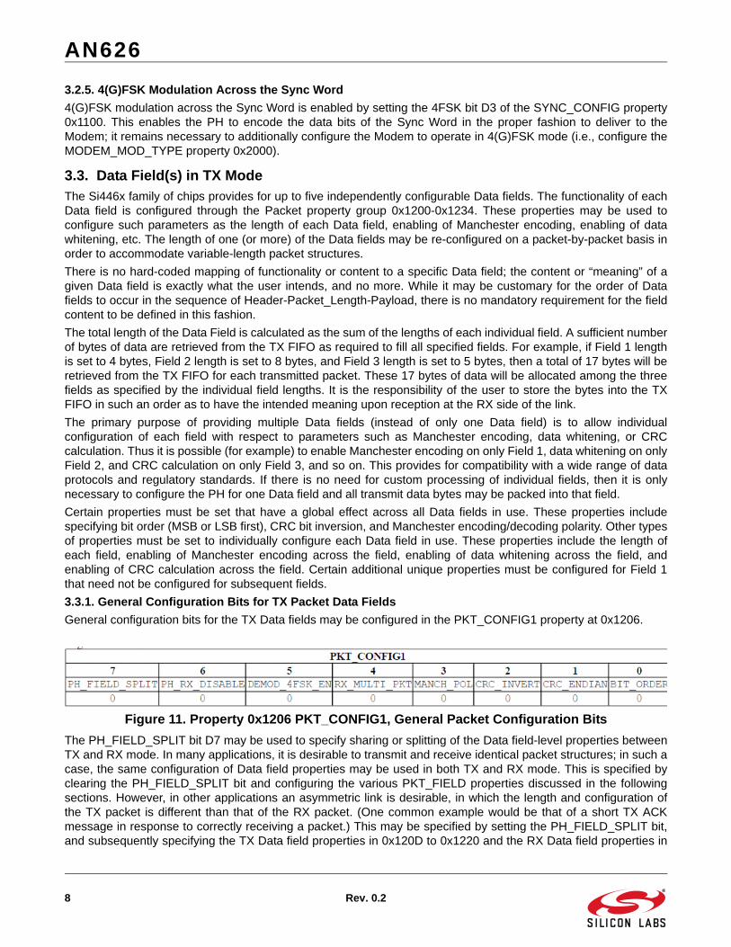
3.3.1. General Configuration Bits for TX Packet Data Fields
General configuration bits for the TX Data fields may be configured in the PKT_CONFIG1 property at 0x1206.
Figure 11. Property 0x1206 PKT_CONFIG1, General Packet Configuration Bits
The PH_FIELD_SPLIT bit D7 may be used to specify sharing or splitting of the Data field-level properties betweenTX and RX mode. In many applications, it is desirable to transmit and receive identical packet structures; in such acase, the same configuration of Data field properties may be used in both TX and RX mode. This is specified byclearing the PH_FIELD_SPLIT bit and configuring the various PKT_FIELD properties discussed in the followingsections. However, in other applications an asymmetric link is desirable, in which the length and configuration ofthe TX packet is different than that of the RX packet. (One common example would be that of a short TX ACKmessage in response to correctly receiving a packet.) This may be specified by setting the PH_FIELD_SPLIT bit,and subsequently specifying the TX Data field properties in 0x120D to 0x1220 and the RX Data field properties in

AN626
Rev. 0.2 9
0x1221 to 0x1234.
The MANCH_POL bit D3 may be used to specify the polarity of Manchester encoding used by all Data fields. IfMANCH_POL = 0, a 0 data bit is encoded to a 10 Manchester bit pattern and a 1 data bit is encoded to a 01Manchester bit pattern. If MANCH_POL =1, a 0 data bit is encoded to a 01 Manchester bit pattern and a 1 data bitis encoded to a 10 Manchester bit pattern.
The CRC_INVERT bit D2 may be used to invert only the transmitted CRC bits. If CRC_INVERT = 0, the CRC bitsare transmitted normally (without inversion). If CRC_INVERT = 1, only the CRC bits are inverted beforetransmission; all remaining bits of the Data fields are transmitted normally.
The CRC_ENDIAN bit D1 may be used to specify which bytes of the CRC checksum are transmitted first. IfCRC_ENDIAN = 0, the low bytes of the CRC checksum(s) are transmitted first. If CRC_ENDIAN = 1, the highbytes of the CRC checksum(s) are transmitted first.
The BIT_ORDER bit D0 may be used to specify which bit of the bytes in the Data field(s) are transmitted first. IfBIT_ORDER = 0, the MSB is transmitted first time-wise for all Data fields. If BIT_ORDER = 1, the LSB istransmitted first time-wise for all Data fields. This bit does not affect the Preamble or Sync fields; the LSB is alwaystransmitted first for the Preamble and Sync fields.
3.3.2. Setting the Field Length
The length of each individual Data field is configured by the PKT_FIELD_X_LENGTH_12_0 properties starting at0x120D-0E, where “X" ranges from 1 to 5. This property specifies the length of the corresponding field in bytes. Avalue of zero in this property means that this field is not used. Data bytes will be retrieved from the TX FIFO andpopulated into fields until the first field with LENGTH = 0 bytes is encountered, or until all five fields are populated(in the event that all fields have a non-zero length). Thus it is not possible to (e.g.) configure Field 1 and Field 3 fornon-zero length and to set Field 2 length = 0 bytes; the TX FIFO will populate only Field 1 and will stop uponencountering unused Field 2.
Figure 12. Property 0x120D-0E PKT_FIELD_1_LENGTH_12_0, Field 1 Length
3.3.3. Configuring Field-Specific Processing
Processing functions such as Manchester encoding, data whitening, and 4(G)FSK modulation may be enabled ordisabled on each individual Data field. These processing functions are configured by the PKT_FIELD_X_CONFIGproperties starting at 0x120F, where “X" ranges from 1 to 5. The various bits that may be configured are as follows:
MANCH bit D0: if set, enables Manchester encoding across the selected field
WHITEN bit D1: if set, enables data whitening across the selected field
PN_START bit D2: if set, loads the PN engine with the seed value at the start of the selected field. (This property is only available for Field 1; it is not possible to re-start the PN engine at the start of any other Data field.)
4FSK bit D4: if set, enables 4(G)FSK processing across the selected field. The Modem must be additionally configured for 4(G)FSK modulation through appropriate setting of the MODEM_MOD_TYPE property; the 4FSK bit simply configures the PH to process the data stream from the TX FIFO as bit pairs (instead of as single bits for 2(G)FSK mode). Simultaneous enabling of Manchester encoding while in

AN626
10 Rev. 0.2
4(G)FSK mode is currently not supported.
Figure 13. Property 0x120F PKT_FIELD_1_CONFIG, Field 1 Custom Processing
3.3.4. Configuring Field-Specific CRC Calculation
CRC checksum calculation may be enabled or disabled on each individual Data field. The CRC functions areconfigured by the PKT_FIELD_X_CRC_CONFIG properties starting at 0x1210, where “X" ranges from 1 to 5. Thevarious bits that are applicable to TX mode are as follows:
CRC_ENABLE bit D1: if set, calculation of the CRC checksum is enabled across the selected field.
SEND_CRC bit D5: if set, the CRC checksum is appended to and transmitted at the end of the selected field.
CRC_START bit D7: if set, loads the CRC engine with the seed value at the start of the selected field. (This property is only available for Field 1; it is not possible to re-start the CRC engine at the start of any other Data field.)
Figure 14. Property 0x1210 PKT_FIELD_1_CRC_CONFIG, Field 1 CRC Configuration
While it is usually customary to send only one CRC checksum at the very end of the packet structure, the PH maybe configured to transmit a CRC checksum after any desired Data field (or after more than one Data field, ifdesired). The calculation of the CRC checksum may also span across non-contiguous Data fields. Thus it ispossible (for example) to enable CRC across Field 1 and Field 3, but to disable it across Field 2.
3.3.5. Selection of the CRC Polynomial
Selection of the CRC polynomial is done by the PKT_CRC_CONFIG property at 0x1200. The selected polynomialis applied to each and every field for which CRC calculation has been enabled; it is currently not possible to usemore than one CRC polynomial within the same packet. The seed value for the polynomial is determined byCRC_SEED bit D7. If CRC_SEED = 0, then all 0’s are used for the CRC seed value; if CRC_SEED = 1, then all 1’sare used for the CRC seed value.
Figure 15. Property 0x1200 PKT_CRC_CONFIG, Global CRC Polynomial Configuration
The CRC polynomial is selected by the CRC_POLYNOMIAL[3:0] field as follows:
0 = No CRC (polynomial coefficients are all 0s)
1 = X8 + X2 + X + 1

AN626
Rev. 0.2 11
2 = X16 + X14 + X12 + X11 + X9 + X8 + X7 + X4 + X + 1
3 = X16 + X15 + X12 + X7 + X6 + X4 + X3 + 1
4 = X16 + X15 + X2 +1
5 = X16 + X12 + X5 + 1
6 = X32+X30+X29+X28+X26+X20+X19+X17+X16+X15+X11+X10+X7+X6+X4+X2+X+1
7 = X32+X26+X23+X22+X16+X12+X11+X10+X8+X7+X5+X4+X2+X+1
8 = X32+X28+X27+X26+X25+X23+X22+X20+X19+X18+X14+X13+X11+X10+X9+X8+X6+1
Selection of CRC_POLYNOMIAL=0 does not result in disabling of CRC generation/checking, but instead sets theCRC polynomial coefficients to all zeroes. The proper method of disabling CRC is by clearing the CRC_ENABLEbit(s) in the appropriate PKT_FIELD_X_CRC_CONFIG properties.
3.3.6. Construction of a Variable Length TX Packet
The concept of a variable length packet in has little meaning in TX mode. There is no means of specifying a field asautomatically variable in length when in TX mode; the length of each field is simply defined by its correspondingPKT_FIELD_X_LENGTH_12_0 property value. If all PKT_FIELD_X_LENGTH properties do not change frompacket to packet, the packet is fixed in length. If one of the PKT_FIELD_X_LENGTH properties is re-programmedand modified between successive packets, the packet is (by definition) variable in length.
There are two methods by which TX packets with differing lengths may be constructed:
Invoke the START_TX command with the TX_LEN parameter set to the desired number of bytes for each packet.
Between packets, reconfigure the appropriate PKT_FIELD_X_LENGTH property for the desired number of bytes.
The first method is by far the simplest of the two methods. In this scenario, the number of data bytes specified bythe TX_LEN parameter (passed to the START_TX command) are retrieved from the TX FIFO and packed into DataField 1; there is no need to additionally configure the PKT_FIELD_1_LENGTH property on a packet-to-packetbasis.
However, the downside of this approach is that all of the transmit data bytes are populated into Data Field 1, andthus there is no ability to apply different processing functions (i.e., Manchester encoding, data whitening, CRCchecksum calculation) across different fields. When invoking the START_TX command with a passed TX_LENparameter, the settings for the processing functions are taken from the existing settings for Field 1. If customprocessing functions are required across different Data fields, it is necessary to invoke the START_TX commandwith a passed TX_LEN parameter of zero bytes and then fully configure each desired Data Field, as described inthe sections above. If the START_TX command is invoked with a non-zero value for the TX_LEN parameter, anypreviously-configured value of the PKT_FIELD_1_LENGTH_12_0 property is overwritten by the passedTX_LEN_value.
For variable length packets, the RX side of the link obviously requires information regarding the packet length inorder to correctly receive the packet. This packet length information is not automatically inserted into thetransmitted packet structure. It is necessary for the user to explicitly load byte(s) containing the packet lengthinformation into the TX FIFO buffer, where they are retrieved and transmitted as any other data byte. Thus it is veryimportant for the user to ensure that the correct value(s) of bytes are loaded into the TX FIFO at the location in thepacket structure where the RX node expects to receive the packet length information.
In a similar fashion, Header or Match bytes are also not automatically inserted or appended to the transmit packetstructure; it is necessary to explicitly load them into the TX FIFO for transmission with each packet.
3.3.7. Match (Header Bytes) in TX Packet
The Si446x family of chips provides for fully configurable Matching functionality on up to 4 data bytes in the DataField(s) of the packet. The Match functionality is performed on the RX node, and thus there is no specialconfiguration required to enable Match functionality on the TX side of the link. It is simply necessary for the user toensure that the correct value(s) of bytes are loaded into the TX FIFO at the location(s) in the packet structurewhere the RX node expects to receive the Match byte(s). The chip does not automatically insert pre-defined Matchbyte(s) into the packet structure; they must be explicitly loaded into the TX FIFO by the user. On the TX side of thelink these bytes appear as any other data bytes loaded into the TX FIFO. The intended meaning of each byte in the

AN626
12 Rev. 0.2
TX FIFO cannot be inferred until the configuration of the corresponding RX node is defined.
3.3.8. Setting the TX FIFO Almost Empty Threshold
The TX FIFO is 64 bytes in length. Packets of greater length may be accommodated by making use of aprogrammable threshold contained in the PKT_TX_THRESHOLD property at 0x120B.
Figure 16. Property 0x120B PKT_TX_THRESHOLD, TX Almost Empty Threshold
The TX_THRESHOLD[7:0] field in this property specifies the TX FIFO Almost Empty Threshold, in number ofbytes. When enough data has been shifted out of the TX FIFO such that the remaining empty space in the bufferis equal to or exceeds the almost empty threshold value, an interrupt will be generated. The host microcontrollermust switch out of TX mode or fill more data into the TX FIFO.
4. Packet Handler in RX Mode
The functionality of the PH may be enabled or disabled in RX mode. Enabling/disabling of the PH functionality isprovided in Property 0x1206 PKT_CONFIG1 by the PH_RX_DISABLE bit D6. The PH may only be disabled whenthe chip is operated in RX Direct mode; the functionality of the PH is required when operating in RX FIFO mode.Furthermore, the PH must remain enabled in some applications in Direct mode. One such example is reception ofa packet with non-standard Preamble; while detection of a standard Preamble structure is performed in theModem, detection of a non-standard Preamble is performed in the PH and thus it must remain enabled, even inDirect mode.
Figure 17. Property 0x1206 PKT_CONFIG1, General Packet Configuration Bits
4.1. Preamble FieldThe Preamble field is configured through the Preamble property group 0x1000-0x1008. These properties may beused to configure parameters such as selection of a standard or non-standard preamble pattern, preambledetection threshold, and invalid preamble timeout.
4.1.1. Selection of Standard or Non-Standard Preamble
Selection of standard or non-standard Preamble pattern is specified by the STANDARD_PREAM[1:0] field in thePREAMBLE_CONFIG property 0x1004. A standard preamble pattern is one that consists of an alternating patternof 1’s and 0’s, such as a 1010 pattern or a 0101 pattern. A 1010 pattern may be selected by settingSTANDARD_PREAM = 2’b01, while a 0101 pattern may be selected by setting STANDARD_PREAM = 2’b10.Selection of either of those two standard preamble patterns results in identical operation in RX mode; the receivercannot ensure that it received the first bit of the transmission as it may have been enabled in mid-packet, and thuscannot tell the difference between the two patterns anyway.
A non-standard preamble pattern is any regularly-repeating pattern that does not consist of alternating 1’s and 0’s.An example of a non-standard preamble pattern might be 11101110. Operation with a non-standard pattern may beselected by setting STANDARD_PREAM = 2’b00. It is necessary to additionally specify the actual structure of thenon-standard repeating pattern, as discussed in “3.1.3. Configuration of Non-Standard Preamble Pattern” .
From the standpoint of the receiver, selection of standard or non-standard preamble determines whether the

AN626
Rev. 0.2 13
qualification of the Preamble is performed in the Modem or in the PH. Qualification of the Preamble (i.e.,generation of a PREAMBLE_VALID signal) is optimized when performed in the Modem, but is not possible whenthe pattern is not a regularly-alternating pattern of 1’s and 0’s.
Figure 18. Property 0x1004 PREAMBLE_CONFIG, Standard/Non-Standard Preamble Selection
4.1.2. Configuration of Non-Standard Preamble Pattern
When operation with a non-standard Preamble pattern has been selected by setting STANDARD_PREAM = 2’b00,it is additionally necessary to specify the desired non-standard pattern to be received. There are two aspects toconfiguring the non-standard Preamble pattern:
Setting the number of bits that will be repeated (PATTERN_LENGTH)
Configuring the actual value of this repetitive pattern (PREAMBLE_PATTERN_31_0)
Figure 19. Property 0x1002 PREAMBLE_CONFIG_NSTD, Length of Non-Standard Pattern
A complete discussion of the configuration of these properties was provided in “3.1.3. Configuration of Non-Standard Preamble Pattern” and will not be repeated here.
4.1.3. Preamble Detection Threshold
The Modem/PH provides Preamble Detection functionality to qualify reception of a signal with a valid Preamble.Preamble detection in the Modem of Standard Preambles remains available even if the PH_RX_DISABLE bit is setin property PKT_CONFIG1 at 0x1206. Preamble detection in the PH (required for reception of non-standardPreambles) is not available if the PH_RX_DISABLE bit is set.
The Preamble Detector circuitry searches for a minimum number of consecutive Preamble pattern bits (e.g.,“0101…’ for a standard Preamble), as specified in the RX_THRESH[6:0] field in the PREAMBLE_CONFIG_STD_1property at 0x1001. The value in this field corresponds to the number of consecutive bits that must be receivedcorrectly before a valid Preamble is considered to have been received. The RX_THRESH [6:0] value only specifiesthe threshold for detection of Standard Preambles; the detection threshold for Non-Standard Preambles isspecified by the PREAMBLE_CONFIG_NSTD: PATTERN_LENGTH parameter.
Figure 20. Property 0x1001 PREAMBLE_CONFIG_STD_1, Preamble Detection Threshold
Upon correctly receiving the number of Preamble bits specified by the RX_THRESH[6:0] field, the chip issues aPREAMBLE_DETECT signal. The PREAMBLE_DETECT signal generated by the Modem (for qualification of

AN626
14 Rev. 0.2
Standard Preamble patterns) may be directly observed as an output on a GPIO pin as selected by theGPIO_PIN_CONFIG command; the PREAMBLE_DETECT signal generated by the PH (for qualification of Non-Standard Preamble patterns) is not currently selectable as an output signal on a GPIO pin. A typicalPREAMBLE_DETECT signal is shown in Figure 21. If Sync Word is successfully detected, thePREAMBLE_DETECT signal remains high for the duration of the packet; if the Sync Word is not detected, thesearch for Sync Word times out and the chip returns to searching for another Preamble. The chip may also beconfigured to generate an interrupt upon detection of the PREAMBLE_DETECT signal.
Detection of the Preamble is normally required for proper reception of the packet. Prior to issuing thePREAMBLE_DETECT signal, the bit clock recovery (BCR) circuitry operates in fast tracking mode. This allows forfast acquisition of bit clock timing, but results in higher clock jitter. If the chip were to remain in this fast trackingmode during the reception of the remainder of the packet, bit errors would likely result due to this excess clockjitter. Acquisition of the PREAMBLE_DETECT signal is commonly used as the gear switching event that signals thechip to switch to a slow tracking mode, resulting in lower clock jitter and error-free reception of bits.
However, it is possible to completely skip detection of the Preamble. A value of RX_THRESH[6:0] = 0 is a legalvalue, and results in skipping the Preamble Detection process. The chip will issue a PREAMBLE_DETECT signalimmediately upon entering RX mode (i.e., a constant HIGH signal). This setting is likely useful only in applicationsin which there is no well-defined Preamble pattern, and it is desired to immediately proceed to searching for SyncWord.
Figure 21. Typical PREAMBLE_DETECT and SYNC_DETECT Signals
4.1.4. Allowed Errors During Preamble Detection
If the Preamble Detection functionality is provided by the PH (as configured by selecting reception of a non-standard Preamble), it is possible to configure the PH to tolerate a small number of errors and yet consider thepattern as valid. The number of errors to be tolerated is specified by the RX_ERRORS[2:0] field in thePREAMBLE_CONFIG_NSTD property 0x1002, in number of bits. This field applies only to reception of a non-standard Preamble; no bit errors are tolerated during reception of a standard Preamble pattern by the detectioncircuitry based in the Modem. However, it is possible to select reception of a non-standard Preamble (thus enabling
AN626
Rev. 0.2 15
the PH-based detection circuitry) but program the expected pattern to be a “1010…’ pattern (i.e., a standardPreamble). It would possible to then use the RX_ERRORS field to specify the number of bit errors to be toleratedduring reception of a standard Preamble pattern.
Figure 22. Property 0x1002 PREAMBLE_CONFIG_NSTD, Allowed Errors During Non-Std Preamble
4.1.5. Preamble Detection Timeout
The chip may be configured to provide an indication if a valid Preamble is not detected within a given period oftime. This functionality is useful when rapidly scanning channels for the detection of a valid signal, as in afrequency hopping system. Support of two different frequency hopping scenarios is provided:
The transmitter sends a very long Preamble, providing sufficient time for a receiver to rapidly scan all channels to search for the signal
The transmitter rapidly hops through all channels, while the receiver waits on one channel for the transmitter to arrive on that frequency
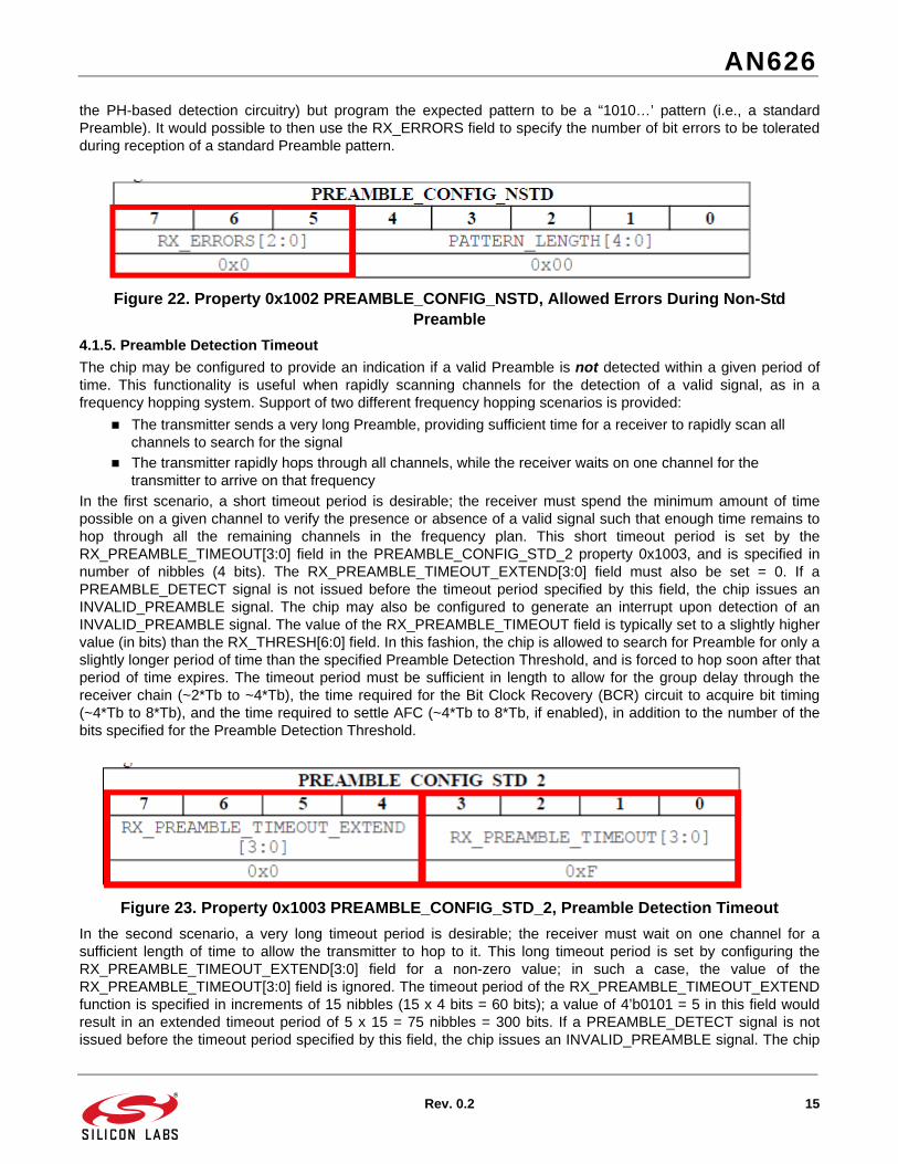
In the first scenario, a short timeout period is desirable; the receiver must spend the minimum amount of timepossible on a given channel to verify the presence or absence of a valid signal such that enough time remains tohop through all the remaining channels in the frequency plan. This short timeout period is set by theRX_PREAMBLE_TIMEOUT[3:0] field in the PREAMBLE_CONFIG_STD_2 property 0x1003, and is specified innumber of nibbles (4 bits). The RX_PREAMBLE_TIMEOUT_EXTEND[3:0] field must also be set = 0. If aPREAMBLE_DETECT signal is not issued before the timeout period specified by this field, the chip issues anINVALID_PREAMBLE signal. The chip may also be configured to generate an interrupt upon detection of anINVALID_PREAMBLE signal. The value of the RX_PREAMBLE_TIMEOUT field is typically set to a slightly highervalue (in bits) than the RX_THRESH[6:0] field. In this fashion, the chip is allowed to search for Preamble for only aslightly longer period of time than the specified Preamble Detection Threshold, and is forced to hop soon after thatperiod of time expires. The timeout period must be sufficient in length to allow for the group delay through thereceiver chain (~2*Tb to ~4*Tb), the time required for the Bit Clock Recovery (BCR) circuit to acquire bit timing(~4*Tb to 8*Tb), and the time required to settle AFC (~4*Tb to 8*Tb, if enabled), in addition to the number of thebits specified for the Preamble Detection Threshold.
Figure 23. Property 0x1003 PREAMBLE_CONFIG_STD_2, Preamble Detection Timeout
In the second scenario, a very long timeout period is desirable; the receiver must wait on one channel for asufficient length of time to allow the transmitter to hop to it. This long timeout period is set by configuring theRX_PREAMBLE_TIMEOUT_EXTEND[3:0] field for a non-zero value; in such a case, the value of theRX_PREAMBLE_TIMEOUT[3:0] field is ignored. The timeout period of the RX_PREAMBLE_TIMEOUT_EXTENDfunction is specified in increments of 15 nibbles (15 x 4 bits = 60 bits); a value of 4’b0101 = 5 in this field wouldresult in an extended timeout period of 5 x 15 = 75 nibbles = 300 bits. If a PREAMBLE_DETECT signal is notissued before the timeout period specified by this field, the chip issues an INVALID_PREAMBLE signal. The chip

AN626
16 Rev. 0.2
may also be configured to generate an interrupt upon detection of an INVALID_PREAMBLE signal.
4.2. Detection of Sync Word FieldThe PH provides Sync Word Detector functionality to verify that the packet is intended for the receiver in use. Thisfunctionality is available only when the PH is enabled by clearing the PH_RX_DISABLE bit D6 of thePKT_CONFIG1 property 0x1206, as the detection of the Sync Word is performed in the PH. Detection of the SyncWord is required for operation in FIFO Mode, as the chip uses the Sync Word to detect the start of the PayloadData field(s) that will be stored in the RX FIFO.
The Sync Word field is configured through the Sync property group 0x1100-0x1104. These properties may be usedto configure such parameters as the number of bytes in the Sync Word and the actual value of the Sync Wordbytes.
4.2.1. Setting the Length of the Sync Word
The length of the expected Sync Word is specified by the value of the LENGTH[1:0] field in the SYNC_CONFIGproperty 0x1100. The length of the Sync Word is equal to LENGTH[1:0] + 1, in bytes. As the value of the LENGTHfield can range from 0 to 3, the number of bytes in the Sync Word can range from 1 to 4 bytes. For example, avalue of LENGTH[1:0] = 2’b00 corresponds to a length of 1 byte, while a value of LENGTH[1:0] = 2’b11corresponds to a length of 4 bytes.
Figure 24. Property 0x1100 SYNC_CONFIG, General Sync Word Configuration Bits
4.2.2. Setting the Values of the Sync Word Bytes
The actual values of the expected Sync Word bytes are specified in the SYNC_BITS_31_0 properties 0x1101-0x1104 (refer to Figure 9).
The Sync Word Detector circuitry searches for the number of Sync Word bytes specified by the LENGTH[1:0] fieldin the SYNC_CONFIG property 0x1100. Because the length of Preamble may be much greater than theRX_THRESH[6:0] value, the PREAMBLE_DETECT signal may be detected quite early during the Preamble. Thusthere may be a significant number of remaining bits of Preamble before the Sync Word actually starts. The SyncWord detection process does not begin until a non-Preamble bit is received; that is, a bit that clearly does not fit inwith the selected pattern of Preamble bits is required to trigger the search for Sync Word. Thus it is stronglyrecommended that the user not specify a Sync Word that is similar to the Standard Preamble pattern (e.g., 0xAAhor 0x55h). The chip will remain searching until either the Sync Word is detected, or until the timeout period isexceeded. The timeout period is fixed at the length of the Sync Word plus 4 bits.
The Sync Word bytes are received in descending order. Thus if LENGTH[1:0] = 2’b00 (corresponding to a SyncWord of 1 byte length), then the first received byte of Sync Word is compared against the value specified in SyncWord 3 (SYNC_BITS_31_24). If LENGTH[1:0] = 2’b01 (corresponding to a Sync Word of 2 bytes length), then thefirst received byte is compared against Sync Word 3, followed by comparing the second received byte against thevalue specified in Sync Word 2 (SYNC_BITS_23_16), and so on. Values programmed into Sync Word bit fields areignored if the LENGTH[1:0] field is not configured for a Sync Word length that requires use of those SYNC_BITfields.
Although the Sync Word byte(s) are transmitted (and of course received) in little-endian fashion (bit 0 first, bit 7last), the comparison values stored in SYNC_BITS_31_0 should be entered in big-endian fashion. For example, adesired 2-byte Sync Word pattern of 2DD4h should be entered as SYNC_BITS_31_24 = 0x2D andSYNC_BITS_23_16 = 0xD4 on both the TX and RX sides of the link, although the time-wise appearance of the bitson the air interface will be 0xB42B.
Upon correctly receiving the Sync Word byte(s), the chip issues a SYNC_DETECT signal. This signal may be

AN626
Rev. 0.2 17
directly observed as an output on a GPIO pin as selected by the GPIO_PIN_CONFIG command. A typicalSYNC_DETECT signal is shown in Figure 21. The SYNC_DETECT signal remains high until the end of the packet.The PREAMBLE_DETECT signal does not go low upon detection of the SYNC_DETECT signal, but remains highfor the duration of the packet. The chip may also be configured to generate an interrupt upon detection of theSYNC_DETECT signal.
If the PH fails to detect the Sync Word within the timeout period, the chip issues an INVALID_SYNC signal. Thechip may also be configured to generate an interrupt upon generation of the INVALID_SYNC signal.
4.2.3. Sync Word Search Timeout
It is not possible to configure the PH to completely skip searching for the Sync Word. Detection of the Sync Word isrecommended (but not absolutely required) for proper reception of the packet. Verification of the Sync Word is thechip’s primary method of determining whether the received packet is intended for it, or is coming from an undesiredtransmitter. Also, detection of the Sync Word is required to determine the start of the Payload Data fields, and thusdata bytes cannot be stored into the RX FIFO if the Sync Word is not detected. Failure to detect the Sync Wordnormally results in the chip switching back to fast tracking mode and resuming search for another Preamble. Thusin order for the chip to remain in slow tracking mode (with resulting low clock jitter), it is important for the chip todetect the Sync Word.
However, it is possible to configure the chip to ignore the Sync Word search timeout. This is done by setting theSKIP_SYNC_TIMEOUT bit D7 in the PREAMBLE_CONFIG_STD_1 property at 0x1001. If this bit is set, the chipstill searches for the Sync Word but doesn’t care if it is detected; the chip will remain in slow tracking mode andcontinue to search for Sync Word after expiration of the Sync Word timeout period.
Figure 25. Property 0x1001 PREAMBLE_CONFIG_STD_1, Skip Sync Word Timeout
4.2.4. Manchester Decoding Across the Sync Word
Manchester decoding of the Sync Word is enabled by setting the MANCH bit D2 of the SYNC_CONFIG property0x1100. The polarity of the Manchester encoding is determined by the MANCH_POL bit D3 in the PKT_CONFIG1property 0x1206 (see “3.3.1. General Configuration Bits for TX Packet Data Fields” ). (This configuration bitdetermines the polarity of Manchester encoding across all packet fields except the Preamble.) The Manchesterdecoding function is performed before the result is compared with the Sync Word value(s) stored inSYNC_BITS_31_0; the values stored should match with the decoded result and not with the Manchester-encodedsequence.
Figure 26. Property 0x1100 SYNC_CONFIG, Manchester Decoding Options
4.2.5. 4(G)FSK Demodulation Across the Sync Word
4(G)FSK processing of the Sync Word is enabled by setting the 4FSK bit D3 of the SYNC_CONFIG property0x1100. This enables the PH to decode the data bits received from the Modem in the proper fashion (i.e., as bitpairs, instead of as single bits); it remains necessary to additionally configure the Modem to operate in 4(G)FSKmode (i.e., configure the MODEM_MOD_TYPE property 0x2000).

AN626
18 Rev. 0.2
4.3. Data Field(s) in RX ModeThe Si446x family of chips provides for up to five independently configurable Data fields. The functionality of eachData field is configured through the Packet property group 0x1200-0x1234. These properties may be used toconfigure such parameters as the length of each Data field, enabling of Manchester decoding, enabling of data de-whitening, etc. The length of one of the Data fields may be re-configured on a packet-by-packet basis in order toaccommodate variable-length packet structures.
There is no hard-coded mapping of functionality or content to a specific Data field; the content or “meaning” of agiven Data field is exactly what the user intends, and no more. While it may be customary for the order of Datafields to occur in the sequence (e.g.) of Header-Packet_Length-Payload, there is no mandatory requirement for thefield content to be defined in this fashion. One restriction is that if a variable-length Data field is present in thepacket, it must occur after the field that contains the byte(s) specifying the length of that variable field. Also, onlyone Data field of variable length may be defined in the packet.
The total length of the Data Field is calculated as the sum of the lengths of each individual field. All of the receiveddata bytes following the Sync Word are stored into the RX FIFO; with the possible exception of the LENGTHbyte(s), no attempt is made to “strip off” certain data bytes prior to placing them into the RX FIFO. It is theresponsibility of the user to retrieve the bytes from the RX FIFO and to process them in such a fashion as to havethe intended meaning during transmission at the TX side of the link.
The primary purpose of providing multiple Data fields (instead of only one Data field) is to allow individualconfiguration of each field with respect to parameters such as Manchester decoding, data de-whitening, CRCchecksum calculation, or logic matching (i.e., Header functionality). Thus it is possible (for example) to enableManchester decoding on only Field 1, data de-whitening on only Field 2, and CRC checksum calculation on onlyField 3, and so on. This provides for compatibility with a wide range of data protocols and regulatory standards. Ifthere is no need for custom processing of individual fields, then it is often only necessary to configure the PH forone Data field and all transmit data bytes may be packed into that field.
Certain properties must be set that have a global effect across all Data fields in use. These properties includespecifying bit order (MSB or LSB first), CRC bit inversion, and Manchester encoding/decoding polarity. Other typesof properties must be set to individually configure each Data field in use. These properties include the length ofeach field, enabling of Manchester decoding across the field, enabling of data de-whitening across the field, andenabling of CRC checksum calculation across the field. Certain additional unique properties must be configured forField 1 that need not be configured for subsequent fields.
4.3.1. General Configuration Bits for RX Packet Data Fields
General configuration bits for the RX Data fields may be configured in the PKT_CONFIG1 property at 0x1206.
Figure 27. Property 0x1206 PKT_CONFIG1, General Packet Configuration Bits
The PH_FIELD_SPLIT bit D7 may be used to specify sharing or splitting of the Data field-level properties betweenTX and RX mode. In many applications, it is desirable to transmit and receive identical packet structures; in such acase, the same configuration of Data field properties may be used in both TX and RX mode. This is specified byclearing the PH_FIELD_SPLIT bit and configuring the various PKT_FIELD properties discussed in the followingsections. However, in other applications an asymmetric link is desirable, in which the length and configuration ofthe TX packet is different than that of the RX packet. (One common example would be that of a short TX ACKmessage in response to correctly receiving a packet.) This may be specified by setting the PH_FIELD_SPLIT bit,and subsequently specifying the TX Data field properties in 0x120D to 0x1220 and the RX Data field properties in0x1221 to 0x1234.
The MANCH_POL bit D3 may be used to specify the polarity of Manchester encoding/decoding used by all Datafields. If MANCH_POL = 0, a 01 Manchester bit pattern is decoded to a 1 data bit while a 10 Manchester bit patternis decoded to a 0 data bit. If MANCH_POL =1, a 01 Manchester bit pattern is decoded to a 0 data bit while a 10

AN626
Rev. 0.2 19
Manchester bit pattern is decoded to a 1 data bit.
The CRC_INVERT bit D2 may be used to invert only the received CRC bits, prior to comparison with thecalculated CRC checksum. If CRC_INVERT = 0, the CRC bits are received normally (without inversion). IfCRC_INVERT = 1, only the received CRC bits are inverted prior to comparison with the calculated CRC checksum;all remaining received Data field bits are stored in the RX FIFO without inversion.
The CRC_ENDIAN bit D1 may be used to specify which bytes of the CRC checksum are expected to be receivedfirst. If CRC_ENDIAN = 0, the low bytes of the CRC checksum(s) are assumed to have been transmitted first. IfCRC_ENDIAN = 1, the high bytes of the CRC checksum(s) are assumed to have been transmitted first.
The BIT_ORDER bit D0 may be used to specify which bit of the bytes in the Data field(s) are assumed to havebeen transmitted first. If BIT_ORDER = 0, the MSB is assumed to have been transmitted first time-wise for all Datafields. If BIT_ORDER = 1, the LSB is assumed to have been transmitted first time-wise for all Data fields. This bitdoes not affect the Preamble or Sync fields; the LSB is always transmitted first for the Preamble and Sync fields.
4.3.2. Setting the Field Length
The length of each individual Data field is configured by the PKT_FIELD_X_LENGTH_12_0 properties starting at0x120D-0E, where “X" ranges from 1 to 5. This property specifies the length of the corresponding field in bytes. Avalue of zero in this property means that this Data field is not used. Data bytes will be received in all non-zerolength fields and stored into the RX FIFO until the first field with LENGTH = 0 bytes is encountered, or until all fivefields are received (in the event that all fields have a non-zero length). Thus it is not possible to (e.g.) configureField 1 and Field 3 for non-zero length and to set Field 2 length = 0 bytes; bytes for storage into the RX FIFO will beretrieved only from Field 1 and will stop upon encountering unused Field 2. In the event that a field is defined asvariable in length (see “4.3.4. Reception of a Variable Length RX Packet” ), the PKT_FIELD_X_LENGTH propertydefines the maximum possible length of the field.
Figure 28. Property 0x120D-0E PKT_FIELD_1_LENGTH_12_0, Field 1 Length
4.3.3. Reception of a Fixed Length RX Packet
There are two methods by which a fixed length RX packet may be received.
Invoke the START_RX command with the RX_LEN parameter set to the desired number of bytes for each packet.
Between packets, reconfigure the appropriate PKT_FIELD_X_LENGTH property for the desired number of bytes.
The first method is by far the simplest of the two methods. In this scenario, the number of data bytes specified bythe RX_LEN parameter (passed to the START_RX command) are assumed to all come from Data Field 1 and arestored into the RX FIFO; there is no need to additionally configure the PKT_FIELD_1_LENGTH property on apacket-to-packet basis.
However, the downside of this approach is that all of the receive data bytes are retrieved from Data Field 1, andthus there is no ability to apply different processing functions (i.e., Manchester encoding, data whitening, CRCchecksum calculation) across different fields. When invoking the START_RX command with a passed RX_LENparameter, the settings for these processing functions are taken from the existing settings for Field 1. If custom

AN626
20 Rev. 0.2
processing functions are required across different Data fields, it is necessary to invoke the START_RX commandwith a passed RX_LEN parameter of zero bytes and then fully configure each desired Data Field, as described inthe sections above. If the START_RX command is invoked with a non-zero value for the RX_LEN parameter, anypreviously-configured value of the PKT_FIELD_1_LENGTH_12_0 property is overwritten by the passed RX_LENvalue.
4.3.4. Reception of a Variable Length RX Packet
It is possible to receive a packet whose Payload Data field length is not known in advance. In such a scenario, thetransmit packet must contain byte(s) that specify the length of the variable field. There is no requirement for thelength byte(s) to occur at one mandatory location in the packet (e.g., immediately following the Sync Word).However, the receiver must obviously know in advance which byte(s) of the received packet represent the lengthvalue. Furthermore, these length bytes must be located in the packet before the variable length field, else the PH inthe receiver will not have the information in time to allocate the received data bytes to the appropriate Data field.
It is first necessary to specify which of the five possible Data fields should be considered by the receiver ascontaining the byte(s) of the received length value. This is specified by the SRC_FIELD[2:0] value in thePKT_LEN_FIELD_SOURCE property 0x1209. The valid range of values of this field is from 0 to 4; the source fieldfor the received length bytes cannot be Data Field 5, as it would then necessarily occur after the variable lengthfield (an invalid condition). A value of SRC_FIELD = 0 is considered the same as selecting Data Field 1.
The source field that contains the variable field length byte(s) must necessarily be a fixed length field. That fieldmay contain other bytes of information (e.g., Header bytes) in addition to the variable field length bytes; however,the variable field length byte(s) must occur as the very last byte(s) in that fixed length field.
Figure 29. Property 0x1209 PKT_LEN_FIELD_SOURCE, Packet Length Source Field
Once the source field containing the length byte(s) has been specified, it is necessary to specify the configurationof those length byte(s). This configuration is accomplished by bits in the PKT_LEN property 0x1208.
The SIZE bit D4 specifies the number of bytes comprising the variable field length information. The received lengthvalue is either 1 byte in length (SIZE = 0) or 2 bytes in length (SIZE = 1). As mentioned previously, these byte(s)must be positioned at the very end of its field.
The ENDIAN bit D5 specifies whether the received length value is little-endian (byte-wise). If ENDIAN = 0, thelength field is considered to be held as least significant byte first. If ENDIAN = 1, the received length value isconsidered to be held as most significant byte first.
The IN_FIFO bit D3 specifies whether or not the received length value will be stored into the RX FIFO. If IN_FIFO= 0, the data byte(s) comprising the received length value are stripped off and not stored in the RX FIFO. IfIN_FIFO = 1, these bytes are stored in the RX FIFO.
Figure 30. Property 0x1208 PKT_LEN, Packet Length Bytes Configuration
Next, it is necessary to specify the destination field to which the length byte(s) refer. This is configured by settingthe DST_FIELD[2:0] value in bits D2-D0. The valid range of values of this field is 0, and 2 to 5. A value ofDST_FIELD = 0 indicates that there is no variable length Data field (i.e., fixed packet length mode). A value of

AN626
Rev. 0.2 21
DST_FIELD = 1 is necessarily invalid, as the variable-length field must occur after the field containing the lengthbyte(s), and thus cannot be Field 1.
The variable-length field pointed to by DST_FIELD need not immediately follow the SRC_FIELD containing thelength byte(s). As an example, it would be possible for SRC_FIELD =1 and DST_FIELD = 4.
The value of the received length byte(s) at the end of the SRC_FIELD always describes the variable length of onlythe field pointed to by the DST_FIELD parameter. As the complete packet may consist of other fixed length fields inaddition to the variable-length field, the total packet length may thus be different (greater) than the received lengthvalue. The received length value of only the variable-length field may be extracted and returned using thePACKET_INFO command, or may be retrieved directly from the RX FIFO in the event the IN_FIFO bit is set.
Finally, it may be desirable to adjust the received value of the length byte(s) upwards or downwards by a fixedamount of offset. This may be necessary to comply with a variety of regulatory standards or protocols that calculatepacket length in different manners. For example, some protocols may include the received length byte(s)themselves in the calculated overall packet length, while other protocols may exclude them.
The Si446x family of chips assumes that the value of the received length byte(s) embedded in the transmittedpacket does not include the length field itself. For example, if the transmit packet consisted of a total of 8 databytes (2 bytes comprising the length field, followed by 6 bytes of Payload data), it would be expected that the valuetransmitted in the length field would be 6. If this is not the case (due to requirements of complying with a regulatorystandard or protocol), it is necessary for the RX side of the link to apply an adjustment or correction factor. Thisadjustment factor is specified in the LEN_ADJUST[7:0] field in the PKT_LEN_ADJUST property 0x120A.
Figure 31. Property 0x120A PKT_LEN_ADJUST, Packet Length Adjustment
The LEN_ADJUST field is a signed value (-128 to +127), and thus both positive or negative adjustments may bemade to the received value of the length field. The value of the LEN_ADJUST field is added to the value of thereceived length field. Assuming a data protocol in which the length bytes are included in the transmitted lengthfield, and again using the example of a transmit packet of 2 length bytes + 6 payload data bytes, the transmitterwould send a packet with an embedded length field with a value of 8. The receiver would demodulate this receivedlength value and assume that the length of only the data field is 8 bytes. It would be necessary to configure theLEN_ADJUST field in the receiver to modify this value to an effective value of 6 bytes, thus indicating the truelength of the received variable length field. As the Si446x family of chips adds the value in the LEN_ADJUST fieldto the received value of the length field, it would be necessary (in this example) to program the LEN_ADJUST fieldfor a value of –2(0xFE).
Note: Even if a field has been defined as a variable length field (as configured by a valid value of DST_FIELD[2:0]), it stillremains necessary to configure the PKT_FIELD_X_LEN_12_0 property for that field. The value stored in this propertyshould reflect the maximum expected length of the variable field. This provides an upper bound for retrieval of databytes, in the event the reception of the packet length field is corrupted.

AN626
22 Rev. 0.2
4.3.5. Setting the RX FIFO Almost Full Threshold
The RX FIFO is 64 bytes in length. Packets of greater length may be accommodated by making use of aprogrammable threshold contained in the PKT_RX_THRESHOLD property at 0x120C.
Figure 32. Property 0x120C PKT_RX_THRESHOLD, RX Almost Full Threshold
The RX_THRESHOLD[7:0] field in this property specifies the RX FIFO Almost Full Threshold, in number of bytes.When the number of data bytes stored into the RX FIFO equals the almost full threshold value, an interrupt will begenerated. The host microcontroller must switch out of RX mode or retrieve data bytes from the RX FIFO.
4.3.6. Configuring Field-Specific Processing
Processing functions such as Manchester decoding, data de-whitening, and 4(G)FSK processing may be enabledor disabled on each individual Data field. These processing functions are configured by thePKT_FIELD_X_CONFIG properties starting at 0x120F, where “X" ranges from 1 to 5. The various bits that may beconfigured are as follows:
MANCH bit D0: if set, enables Manchester decoding across the selected field
WHITEN bit D1: if set, enables data de-whitening across the selected field
PN_START bit D2: if set, loads the PN engine with the seed value at the start of the selected field. (This property is only available for Field 1; it is not possible to re-start the PN engine at the start of any other Data field.)
4GFSK bit D4: if set, enables 4(G)FSK processing across the selected field. The Modem must be additionally configured for 4(G)FSK demodulation through appropriate setting of the MODEM_MOD_TYPE property; the 4FSK bit simply configures the PH to process the data stream to the RX FIFO as bit pairs (instead of as single bits for 2(G)FSK mode). Simultaneous enabling of Manchester coding while in 4(G)FSK mode is currently not supported.
Figure 33. Property 0x120F PKT_FIELD_1_CONFIG, Field 1 Custom Processing
4.3.7. Configuring Field-Specific CRC Calculation
CRC checksum calculation may be enabled or disabled on each individual Data field. The CRC functions areconfigured by the PKT_FIELD_X_CRC_CONFIG properties starting at 0x1210, where “X" ranges from 1 to 5. Thevarious bits that are applicable to RX mode are as follows:
CRC_ENABLE bit D1: if set, calculation of CRC checksum is enabled across the selected field.
CHECK_CRC bit D3: if set, the calculated CRC checksum is compared at the end of the selected field.
CRC_START bit D7: if set, loads the CRC engine with the seed value at the start of the selected field. (This property is only available for Field 1; it is not possible to re-start the CRC engine at the start of any other Data field.)

AN626
Rev. 0.2 23
Figure 34. Property 0x1210 PKT_FIELD_1_CRC_CONFIG, Field 1 CRC Configuration
While it is usually customary for a packet to contain only one CRC checksum (at the very end of the packet), thePH may be configured to transmit a CRC checksum after any desired Data field (or after more than one Data field,if desired). Thus the receiver must also be configured to process the CRC checksum bytes wherever they mayoccur in the packet. The calculation of the CRC checksum may also span across non-contiguous Data fields. Thusit is possible (for example) to enable CRC calculation across Field 1 and Field 3, disable it across Field 2, and tocheck (compare) the calculated CRC checksum after Field 3.
4.3.8. Selection of the CRC Polynomial
Selection of the CRC polynomial is done by the PKT_CRC_CONFIG property at 0x1200. The selected polynomialis applied to each and every field for which CRC calculation has been enabled; it is not possible to use more thanone CRC polynomial within the same packet. The seed value for the polynomial is determined by CRC_SEED bitD7. If CRC_SEED = 0, then all 0’s are used for the CRC seed value; if CRC_SEED = 1, then all 1’s are used for theCRC seed value.
Figure 35. Property 0x1200 PKT_CRC_CONFIG, Global CRC Polynomial Configuration
The CRC polynomial is selected by the CRC_POLYNOMIAL[3:0] field as follows:
0 = No CRC (polynomial coefficients are all 0s)
1 = X8 + X2 + X + 1
2 = X16 + X14 + X12 + X11 + X9 + X8 + X7 + X4 + X + 1
3 = X16 + X15 + X12 + X7 + X6 + X4 + X3 + 1
4 = X16 + X15 + X2 +1
5 = X16 + X12 + X5 + 1
6 = X32+X30+X29+X28+X26+X20+X19+X17+X16+X15+X11+X10+X7+X6+X4+X2+X+1
7 = X32+X26+X23+X22+X16+X12+X11+X10+X8+X7+X5+X4+X2+X+1
8 = X32+X28+X27+X26+X25+X23+X22+X20+X19+X18+X14+X13+X11+X10+X9+X8+X6+1
Selection of CRC_POLYNOMIAL=0 does not result in disabling of CRC generation/checking but instead sets theCRC polynomial coefficients to all zeros. The proper method of disabling CRC is by clearing the CRC_ENABLEbit(s) in the appropriate PKT_FIELD_X_CRC_CONFIG properties.
4.3.9. Controlling of Storage of Length Byte(s) in RX FIFO
The PH stores the received bytes after the Sync Word field into the RX FIFO, excluding CRC checksum bytes (ifpresent). By default, the received length field byte(s) (in the event of a variable-length packet) are not stored in theRX FIFO. However, it is possible to configure the chip such that the received length field byte(s) (occurring at theend of the field specified by the SRC_FIELD [2:0] value) are not automatically “stripped off” and are thus storedinto the RX FIFO. This is accomplished by setting the IN_FIFO bit D3 in the PKT_LEN property 0x1208.

AN626
24 Rev. 0.2
4.4. Match (Header Check) FunctionalityThe Si446x family of chips provides for fully configurable Matching functionality on up to 4 data bytes in the DataField(s) of the packet. The Match functionality is configured through the MATCH property group at 0x3000-0B. TheMatch function is typically used to implement Header Check or Broadcast Check capability. Header or BroadcastChecking is typically used to quickly determine if a packet is intended for one (or more) receive nodes in a network.If a match is not found, the chip can abort reception of the packet and proceed to scanning for the next packet. TheMatch function is enabled by setting the MATCH_EN bit D6 of the MATCH_CTRL_1 property 0x3002.
Figure 36. Property 0x3002 MATCH_CTRL_1, Match 1 Control Field
Although it is customary for the Match/Header bytes to be located immediately after the Sync Word (thus allowingthe chip to rapidly verify if the packet is intended for that node), there is no mandatory requirement that the Matchbytes be placed in this location. The Si446x family of chips allows the user to define up to 4 Match bytes atconfigurable locations in the packet. The only restraint is that all of the Match bytes must be located within the first32 bytes following the end of the Sync Word.
The location(s) of the received data byte(s) upon which to perform the Match function are specified by theOFFSET[4:0] field in each MATCH_CTRL_X property. The value in this field represents the offset in number ofbytes of the location of the received data byte to match, relative to the end of the Sync Word. Thus if it is desired tomatch against the first byte immediately following the Sync Word, this field would be set to OFFSET = 0. SettingOFFSET = 1 would match against the second byte following the Sync Word, and so on. It is also necessary that theoffset(s) of the Match bytes be in non-descending order; that is, the offset location of Match 1 byte must be lessthan or equal to the location of Match 2 byte, the offset location of Match 2 byte must be less than or equal to thelocation of Match 3 byte, and so on. Two (or more) Match bytes may have the same offset location.
Once the location of each Match byte has been specified, it is next necessary to configure their mask values. Amask value represents a bit pattern which is logically AND’ed (bit-wise) with the corresponding received Matchbyte. These mask values are specified in the MASK_X[7:0] fields where “X" can range from 1 to 4, and accessedthrough the MATCH_MASK_X properties (e.g., MATCH_MASK_1 at 0x3001). For example, if it is desired to matchonly the top 4 bits of the first Match byte, it would be necessary to set MATCH_MASK_1[7:0] = 0xF0.
The result is then compared with the corresponding match value. The match values are specified in theVALUE_X[7:0] fields where “X" can again range from 1 to 4, and accessed through the MATCH_VALUE_Xproperties (e.g., MATCH_VALUE_1 at 0x3000).
Figure 37. Property 0x3000-01 MATCH_VALUE_1, Match 1 Value and Mask
AN626
Rev. 0.2 25
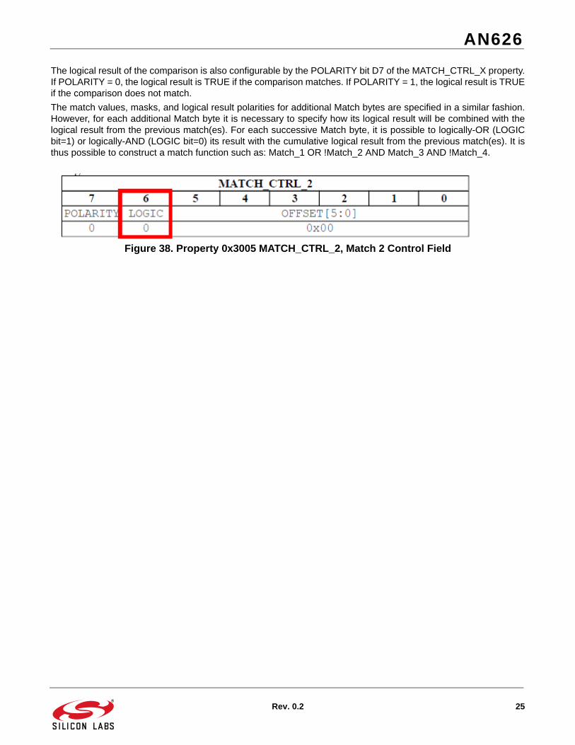
The logical result of the comparison is also configurable by the POLARITY bit D7 of the MATCH_CTRL_X property.If POLARITY = 0, the logical result is TRUE if the comparison matches. If POLARITY = 1, the logical result is TRUEif the comparison does not match.
The match values, masks, and logical result polarities for additional Match bytes are specified in a similar fashion.However, for each additional Match byte it is necessary to specify how its logical result will be combined with thelogical result from the previous match(es). For each successive Match byte, it is possible to logically-OR (LOGICbit=1) or logically-AND (LOGIC bit=0) its result with the cumulative logical result from the previous match(es). It isthus possible to construct a match function such as: Match_1 OR !Match_2 AND Match_3 AND !Match_4.
Figure 38. Property 0x3005 MATCH_CTRL_2, Match 2 Control Field

AN626
26 Rev. 0.2
5. Example Scripts
5.1. TX ModeThe following are some example scripts demonstrating operation of the Packet Handler in TX mode. Each scripthas certain API calls in common to accomplish basic functions such as setting the desired frequency of operation,setting the data rate and deviation, setting the TX output power level, etc. The scripts differ primarily inconfiguration of the PH and Preamble. All scripts assume a desired transmit frequency of 915.0 MHz, 2GFSKmodulation at a data rate of 5 kbps and a deviation of 1.625 kHz.
5.1.1. Fixed-Length Packet Structure (Preamble + Sync + Payload + CRC)
A simple packet structure to create is one that contains a standard Preamble (i.e., “0101’ pattern), Sync Word,several bytes of Payload data, and a CRC checksum.
#BatchName TX 915.0 MHz ClassE +20dBm 2GFSK Packet
# XO30M DR5K Dev1.625K wCRC FxdLen LoopBW=200kHz
# Revision Date: 5/8/2013, IQCalc=6381
# Start
RESET
'POWER_UP' 01 00 01 C9 C3 80
'PART_INFO'
'FUNC_INFO'
# Adjust Crystal Osc cap bank to center oscillator frequency
'SET_PROPERTY' 'GLOBAL_XO_TUNE' 4B
# Set interrupts = Packet Sent
'SET_PROPERTY' 'INT_CTL_ENABLE' 05
'SET_PROPERTY' 'INT_CTL_PH_ENABLE' 20
# Read and clear any existing interrupts
'GET_INT_STATUS' 00 00 00
# General parameters, Mod Type = 2GFSK, Packet FIFO
'SET_PROPERTY' 'MODEM_MOD_TYPE' 03
'SET_PROPERTY' 'MODEM_MAP_CONTROL' 00
'SET_PROPERTY' 'MODEM_CLKGEN_BAND' 08
# Freq control group = 915.0 MHz
'SET_PROPERTY' 'FREQ_CONTROL_INTE' 3C
'SET_PROPERTY' 'FREQ_CONTROL_FRAC_2' 08
'SET_PROPERTY' 'FREQ_CONTROL_FRAC_1' 00
'SET_PROPERTY' 'FREQ_CONTROL_FRAC_0' 00
'SET_PROPERTY' 'FREQ_CONTROL_W_SIZE' 20
# PA control group = Class-E, +20 dBm

AN626
Rev. 0.2 27
'SET_PROPERTY' 'PA_MODE' 08
'SET_PROPERTY' 'PA_PWR_LVL' 7F
'SET_PROPERTY' 'PA_BIAS_CLKDUTY' 00
'SET_PROPERTY' 'PA_TC' 3D
# Tx parameters, DR=5kbps, Dev=1.625kHz, TXOSR=40
'SET_PROPERTY' 'MODEM_DATA_RATE_2' 00
'SET_PROPERTY' 'MODEM_DATA_RATE_1' 4E
'SET_PROPERTY' 'MODEM_DATA_RATE_0' 20
'SET_PROPERTY' 'MODEM_TX_NCO_MODE_3' 04
'SET_PROPERTY' 'MODEM_TX_NCO_MODE_2' 2D
'SET_PROPERTY' 'MODEM_TX_NCO_MODE_1' C6
'SET_PROPERTY' 'MODEM_TX_NCO_MODE_0' C0
'SET_PROPERTY' 'MODEM_FREQ_DEV_2' 00
'SET_PROPERTY' 'MODEM_FREQ_DEV_1' 00
'SET_PROPERTY' 'MODEM_FREQ_DEV_0' 39
'SET_PROPERTY' 'MODEM_TX_RAMP_DELAY' 01
# Set Preamble = Std '0101, Length = 5 bytes
'SET_PROPERTY' 'PREAMBLE_TX_LENGTH' 05
'SET_PROPERTY' 'PREAMBLE_CONFIG' 12
# Set Sync word = 2 bytes = 0xB42B (sent little-endian = 0x2DD4 over air interface)
'SET_PROPERTY' 'SYNC_CONFIG' 01
'SET_PROPERTY' 'SYNC_BITS_31_24' B4
'SET_PROPERTY' 'SYNC_BITS_23_16' 2B
# Enable CRC, set the X15+X12+X5+1 16-bit polynomial, seed value = 1's
'SET_PROPERTY' 'PKT_CRC_CONFIG' 85
# Set fixed packet length, Field-1 = 10 bytes, CRC across Field-1, load seed value
'SET_PROPERTY' 'PKT_LEN' 00
'SET_PROPERTY' 'PKT_FIELD_1_LENGTH_12_8' 00
'SET_PROPERTY' 'PKT_FIELD_1_LENGTH_7_0' 0A
'SET_PROPERTY' 'PKT_FIELD_1_CONFIG' 00
'SET_PROPERTY' 'PKT_FIELD_1_CRC_CONFIG' A2
# Load 10-bytes of arbitrary data into TX FIFO
'WRITE_TX_FIFO' 01 02 03 04 05 06 07 08 09 0A
# Start transmitting, return to READY after packet

AN626
28 Rev. 0.2
'START_TX' 00 30 00 00
5.1.2. Variable-Length Packet Structure (Preamble + Sync + Length + Payload +CRC)
The following packet structure builds upon the basic script shown in “5.1.1. Fixed-Length Packet Structure(Preamble + Sync + Payload + CRC)” , but modifies the PH section to provide for a variable-length Data field.
As discussed in “3.3.6. Construction of a Variable Length TX Packet” , it is necessary for the user to explicitly loadthe bytes containing the packet length info into the TX FIFO; the chip does not automatically append these bytes tothe packet. In the example script shown below, the Length field bytes are the first two bytes (00 0A) of theWRITE_TX_FIFO command; the remaining bytes are considered the Payload Data bytes. Note that there is nomeans of specifying a field as variable in length when in TX mode; the length of each field is simply defined by itscorresponding PKT_FIELD_X_LENGTH_12_0 property value. If these field value(s) are unchanging from packet topacket, the packet is fixed in length. If these field value(s) are modified between successive packets, the packet isvariable in length. In this example, there is no requirement for field-specific processing and thus both the lengthbytes and the Payload bytes may be packed into the same field (i.e., Field 1).
#BatchName TX 915.0 MHz ClassE +20dBm 2GFSK Packet
# XO30M DR5K Dev1.625K wCRC VarLen LoopBW=200kHz
# Revision Date: 5/8/2013, IQCalc=6381
# Start
RESET
'POWER_UP' 01 00 01 C9 C3 80
'PART_INFO'
'FUNC_INFO'
# Adjust Crystal Osc cap bank to center oscillator frequency
'SET_PROPERTY' 'GLOBAL_XO_TUNE' 4B
# Set interrupts = Packet Sent
'SET_PROPERTY' 'INT_CTL_ENABLE' 05
'SET_PROPERTY' 'INT_CTL_PH_ENABLE' 20
# Read and clear any existing interrupts
'GET_INT_STATUS' 00 00 00
# General parameters, Mod Type = 2GFSK, Packet FIFO
'SET_PROPERTY' 'MODEM_MOD_TYPE' 03
'SET_PROPERTY' 'MODEM_MAP_CONTROL' 00
'SET_PROPERTY' 'MODEM_CLKGEN_BAND' 08
# Freq control group = 915.0 MHz
'SET_PROPERTY' 'FREQ_CONTROL_INTE' 3C
'SET_PROPERTY' 'FREQ_CONTROL_FRAC_2' 08
'SET_PROPERTY' 'FREQ_CONTROL_FRAC_1' 00
'SET_PROPERTY' 'FREQ_CONTROL_FRAC_0' 00
'SET_PROPERTY' 'FREQ_CONTROL_W_SIZE' 20

AN626
Rev. 0.2 29
# PA control group = Class-E, +20 dBm
'SET_PROPERTY' 'PA_MODE' 08
'SET_PROPERTY' 'PA_PWR_LVL' 7F
'SET_PROPERTY' 'PA_BIAS_CLKDUTY' 00
'SET_PROPERTY' 'PA_TC' 3D
# Tx parameters, DR=5kbps, Dev=1.625kHz, TXOSR=40
'SET_PROPERTY' 'MODEM_DATA_RATE_2' 00
'SET_PROPERTY' 'MODEM_DATA_RATE_1' 4E
'SET_PROPERTY' 'MODEM_DATA_RATE_0' 20
'SET_PROPERTY' 'MODEM_TX_NCO_MODE_3' 04
'SET_PROPERTY' 'MODEM_TX_NCO_MODE_2' 2D
'SET_PROPERTY' 'MODEM_TX_NCO_MODE_1' C6
'SET_PROPERTY' 'MODEM_TX_NCO_MODE_0' C0
'SET_PROPERTY' 'MODEM_FREQ_DEV_2' 00
'SET_PROPERTY' 'MODEM_FREQ_DEV_1' 00
'SET_PROPERTY' 'MODEM_FREQ_DEV_0' 39
'SET_PROPERTY' 'MODEM_TX_RAMP_DELAY' 01
# Set Preamble = Std '0101, Length = 5 bytes
'SET_PROPERTY' 'PREAMBLE_TX_LENGTH' 05
'SET_PROPERTY' 'PREAMBLE_CONFIG' 12
# Set Sync word = 2 bytes = 0xB42B (sent little-endian = 0x2DD4 over air interface)
'SET_PROPERTY' 'SYNC_CONFIG' 01
'SET_PROPERTY' 'SYNC_BITS_31_24' B4
'SET_PROPERTY' 'SYNC_BITS_23_16' 2B
# Enable CRC, set the X15+X12+X5+1 16-bit polynomial, seed value = 1's
'SET_PROPERTY' 'PKT_CRC_CONFIG' 85
# Set fixed packet length, Field-1 = 12 bytes, CRC across Field-1, load seed value
'SET_PROPERTY' 'PKT_LEN' 00
'SET_PROPERTY' 'PKT_FIELD_1_LENGTH_12_8' 00
'SET_PROPERTY' 'PKT_FIELD_1_LENGTH_7_0' 0C
'SET_PROPERTY' 'PKT_FIELD_1_CONFIG' 00
'SET_PROPERTY' 'PKT_FIELD_1_CRC_CONFIG' A2
# Load 12-bytes of data into TX FIFO
# First 2 bytes should contain Variable Field Length info for RX node

AN626
30 Rev. 0.2
# (Value of Length bytes should reflect only length of the variable field, 10-bytes in this example)
'WRITE_TX_FIFO' 00 0A 01 02 03 04 05 06 07 08 09 0A
# Start transmitting, return to READY after packet
'START_TX' 00 30 00 00
5.1.3. Variable-Length Packet with Header (Match) Bytes
The following packet structure builds upon the basic script shown in “5.1.2. Variable-Length Packet Structure(Preamble + Sync + Length + Payload +CRC)” , but modifies the PH section to additionally provide for Headerbytes using the Match function.
As discussed in “3.3.7. Match (Header Bytes) in TX Packet” , it is necessary for the user to explicitly load the bytescontaining the Match/Header bytes into the TX FIFO; the chip does not automatically insert pre-defined Matchbytes into the packet. Thus the configuration of the TX node is quite similar to that shown in previous scripts; allthat is different is the “intended meaning” of various bytes placed in the TX FIFO. The intended meaning of eachbyte in the TX FIFO cannot be inferred until the configuration of the corresponding RX node is defined. There isagain no requirement for field-specific processing, and thus the match bytes, length bytes, and Payload bytes mayall be packed into the same field (i.e., Field 1).
#BatchName TX 915.0 MHz ClassE +20dBm 2GFSK Packet
# XO30M DR5K Dev1.625K wCRC wMatch VarLen LoopBW=200kHz
# Revision Date: 5/8/2013, IQCalc=6381
# Start
RESET
'POWER_UP' 01 00 01 C9 C3 80
'PART_INFO'
'FUNC_INFO'
# Adjust Crystal Osc cap bank to center oscillator frequency
'SET_PROPERTY' 'GLOBAL_XO_TUNE' 4B
# Set interrupts = Packet Sent
'SET_PROPERTY' 'INT_CTL_ENABLE' 05
'SET_PROPERTY' 'INT_CTL_PH_ENABLE' 20
# Read and clear any existing interrupts
'GET_INT_STATUS' 00 00 00
# General parameters, Mod Type = 2GFSK, Packet FIFO
'SET_PROPERTY' 'MODEM_MOD_TYPE' 03
'SET_PROPERTY' 'MODEM_MAP_CONTROL' 00
'SET_PROPERTY' 'MODEM_CLKGEN_BAND' 08
# Freq control group = 915.0 MHz
'SET_PROPERTY' 'FREQ_CONTROL_INTE' 3C
'SET_PROPERTY' 'FREQ_CONTROL_FRAC_2' 08

AN626
Rev. 0.2 31
'SET_PROPERTY' 'FREQ_CONTROL_FRAC_1' 00
'SET_PROPERTY' 'FREQ_CONTROL_FRAC_0' 00
'SET_PROPERTY' 'FREQ_CONTROL_W_SIZE' 20
# PA control group = Class-E, +20 dBm
'SET_PROPERTY' 'PA_MODE' 08
'SET_PROPERTY' 'PA_PWR_LVL' 7F
'SET_PROPERTY' 'PA_BIAS_CLKDUTY' 00
'SET_PROPERTY' 'PA_TC' 3D
# Tx parameters, DR=5kbps, Dev=1.625kHz, TXOSR=40
'SET_PROPERTY' 'MODEM_DATA_RATE_2' 00
'SET_PROPERTY' 'MODEM_DATA_RATE_1' 4E
'SET_PROPERTY' 'MODEM_DATA_RATE_0' 20
'SET_PROPERTY' 'MODEM_TX_NCO_MODE_3' 04
'SET_PROPERTY' 'MODEM_TX_NCO_MODE_2' 2D
'SET_PROPERTY' 'MODEM_TX_NCO_MODE_1' C6
'SET_PROPERTY' 'MODEM_TX_NCO_MODE_0' C0
'SET_PROPERTY' 'MODEM_FREQ_DEV_2' 00
'SET_PROPERTY' 'MODEM_FREQ_DEV_1' 00
'SET_PROPERTY' 'MODEM_FREQ_DEV_0' 39
'SET_PROPERTY' 'MODEM_TX_RAMP_DELAY' 01
# Set Preamble = Std '0101, Length = 5 bytes
'SET_PROPERTY' 'PREAMBLE_TX_LENGTH' 05
'SET_PROPERTY' 'PREAMBLE_CONFIG' 12
# Set Sync word = 2 bytes = 0xB42B (sent little-endian = 0x2DD4 over air interface)
'SET_PROPERTY' 'SYNC_CONFIG' 01
'SET_PROPERTY' 'SYNC_BITS_31_24' B4
'SET_PROPERTY' 'SYNC_BITS_23_16' 2B
# Enable CRC, set the X15+X12+X5+1 16-bit polynomial, seed value = 1's
'SET_PROPERTY' 'PKT_CRC_CONFIG' 85
# Set fixed packet length, Field-1 = 14 bytes, CRC across Field-1, load seed value
'SET_PROPERTY' 'PKT_LEN' 00
'SET_PROPERTY' 'PKT_FIELD_1_LENGTH_12_8' 00
'SET_PROPERTY' 'PKT_FIELD_1_LENGTH_7_0' 0E
'SET_PROPERTY' 'PKT_FIELD_1_CONFIG' 00
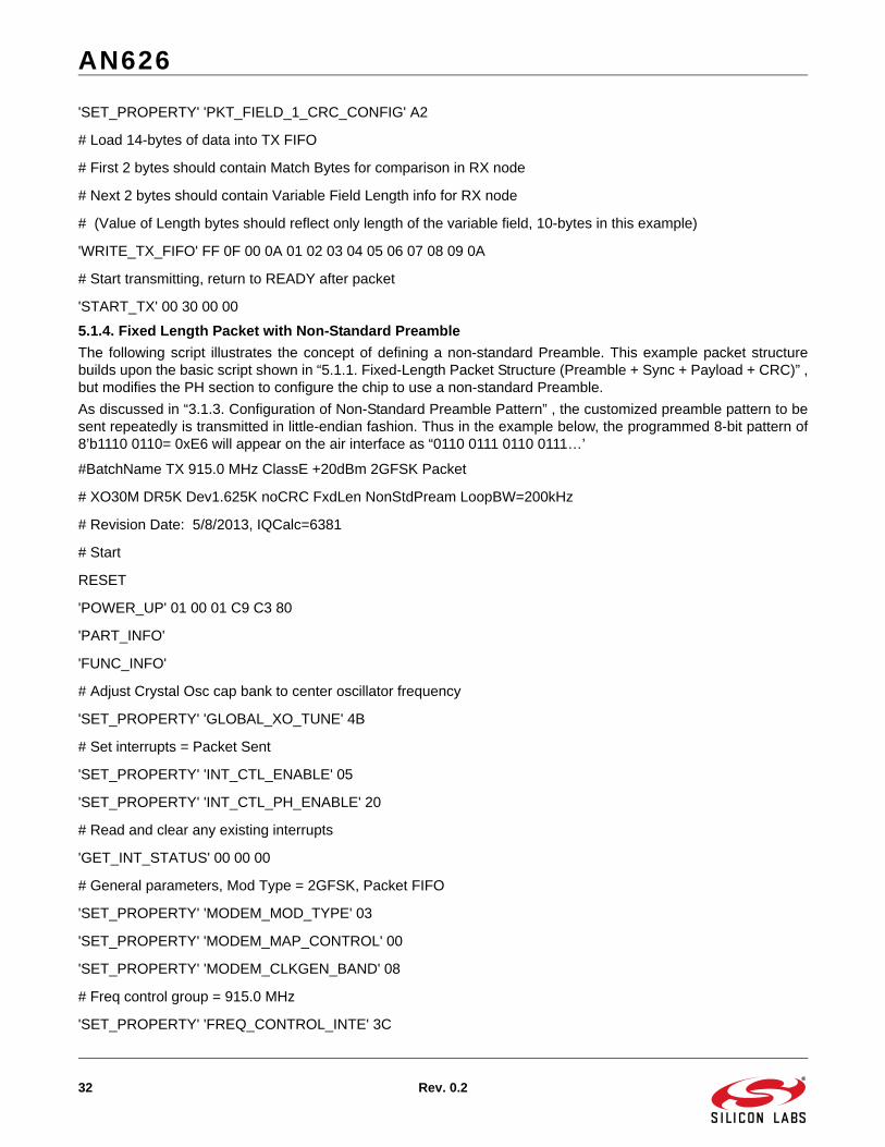
AN626
32 Rev. 0.2
'SET_PROPERTY' 'PKT_FIELD_1_CRC_CONFIG' A2
# Load 14-bytes of data into TX FIFO
# First 2 bytes should contain Match Bytes for comparison in RX node
# Next 2 bytes should contain Variable Field Length info for RX node
# (Value of Length bytes should reflect only length of the variable field, 10-bytes in this example)
'WRITE_TX_FIFO' FF 0F 00 0A 01 02 03 04 05 06 07 08 09 0A
# Start transmitting, return to READY after packet
'START_TX' 00 30 00 00
5.1.4. Fixed Length Packet with Non-Standard Preamble
The following script illustrates the concept of defining a non-standard Preamble. This example packet structurebuilds upon the basic script shown in “5.1.1. Fixed-Length Packet Structure (Preamble + Sync + Payload + CRC)” ,but modifies the PH section to configure the chip to use a non-standard Preamble.
As discussed in “3.1.3. Configuration of Non-Standard Preamble Pattern” , the customized preamble pattern to besent repeatedly is transmitted in little-endian fashion. Thus in the example below, the programmed 8-bit pattern of8’b1110 0110= 0xE6 will appear on the air interface as “0110 0111 0110 0111…’
#BatchName TX 915.0 MHz ClassE +20dBm 2GFSK Packet
# XO30M DR5K Dev1.625K noCRC FxdLen NonStdPream LoopBW=200kHz
# Revision Date: 5/8/2013, IQCalc=6381
# Start
RESET
'POWER_UP' 01 00 01 C9 C3 80
'PART_INFO'
'FUNC_INFO'
# Adjust Crystal Osc cap bank to center oscillator frequency
'SET_PROPERTY' 'GLOBAL_XO_TUNE' 4B
# Set interrupts = Packet Sent
'SET_PROPERTY' 'INT_CTL_ENABLE' 05
'SET_PROPERTY' 'INT_CTL_PH_ENABLE' 20
# Read and clear any existing interrupts
'GET_INT_STATUS' 00 00 00
# General parameters, Mod Type = 2GFSK, Packet FIFO
'SET_PROPERTY' 'MODEM_MOD_TYPE' 03
'SET_PROPERTY' 'MODEM_MAP_CONTROL' 00
'SET_PROPERTY' 'MODEM_CLKGEN_BAND' 08
# Freq control group = 915.0 MHz
'SET_PROPERTY' 'FREQ_CONTROL_INTE' 3C

AN626
Rev. 0.2 33
'SET_PROPERTY' 'FREQ_CONTROL_FRAC_2' 08
'SET_PROPERTY' 'FREQ_CONTROL_FRAC_1' 00
'SET_PROPERTY' 'FREQ_CONTROL_FRAC_0' 00
'SET_PROPERTY' 'FREQ_CONTROL_W_SIZE' 20
# PA control group = Class-E, +20 dBm
'SET_PROPERTY' 'PA_MODE' 08
'SET_PROPERTY' 'PA_PWR_LVL' 7F
'SET_PROPERTY' 'PA_BIAS_CLKDUTY' 00
'SET_PROPERTY' 'PA_TC' 3D
# Tx parameters, DR=5kbps, Dev=1.625kHz, TXOSR=40
'SET_PROPERTY' 'MODEM_DATA_RATE_2' 00
'SET_PROPERTY' 'MODEM_DATA_RATE_1' 4E
'SET_PROPERTY' 'MODEM_DATA_RATE_0' 20
'SET_PROPERTY' 'MODEM_TX_NCO_MODE_3' 04
'SET_PROPERTY' 'MODEM_TX_NCO_MODE_2' 2D
'SET_PROPERTY' 'MODEM_TX_NCO_MODE_1' C6
'SET_PROPERTY' 'MODEM_TX_NCO_MODE_0' C0
'SET_PROPERTY' 'MODEM_FREQ_DEV_2' 00
'SET_PROPERTY' 'MODEM_FREQ_DEV_1' 00
'SET_PROPERTY' 'MODEM_FREQ_DEV_0' 39
'SET_PROPERTY' 'MODEM_TX_RAMP_DELAY' 01
# Set Preamble = Non-Std, Length = 5 bytes
'SET_PROPERTY' 'PREAMBLE_TX_LENGTH' 05
'SET_PROPERTY' 'PREAMBLE_CONFIG' 10
# Set Non-Std Pattern Length = 8bits = 0xE6 (0x67 over air interface)
'SET_PROPERTY' 'PREAMBLE_CONFIG_NSTD' 07
'SET_PROPERTY' 'PREAMBLE_PATTERN_7_0' E6
# Set Sync word = 2 bytes = 0xB42B (sent little-endian = 0x2DD4 over air interface)
'SET_PROPERTY' 'SYNC_CONFIG' 01
'SET_PROPERTY' 'SYNC_BITS_31_24' B4
'SET_PROPERTY' 'SYNC_BITS_23_16' 2B
# Set fixed packet length, Field-1 = 10 bytes
'SET_PROPERTY' 'PKT_LEN' 00
'SET_PROPERTY' 'PKT_FIELD_1_LENGTH_12_8' 00

AN626
34 Rev. 0.2
'SET_PROPERTY' 'PKT_FIELD_1_LENGTH_7_0' 0A
'SET_PROPERTY' 'PKT_FIELD_1_CONFIG' 00
'SET_PROPERTY' 'PKT_FIELD_1_CRC_CONFIG' 00
# Load 10-bytes of arbitrary data into TX FIFO
'WRITE_TX_FIFO' 01 02 03 04 05 06 07 08 09 0A
# Start transmitting, return to READY after packet
'START_TX' 00 30 00 00
5.2. Example Script for Packet Handler in RX ModeThe following are some example scripts demonstrating operation of the Packet Handler in RX mode. Each scripthas certain API calls in common to accomplish basic functions such as setting the desired frequency of operation,setting the loop bandwidth of the PLL, configuring the RX Modem, etc. The scripts differ primarily in configuration ofthe PH and Preamble. All scripts assume a desired receive frequency of 915.0 MHz, 2GFSK modulation at a datarate of 5 kbps and a deviation of 1.625 kHz.
5.2.1. Fixed-Length Packet Structure (Preamble + Sync + Payload
The simplest packet structure to create is one that contains a standard Preamble (i.e., “0101’ pattern), Sync Word,several bytes of Payload data, but no CRC checksum.
#BatchName RX 915.0 MHz Packet 2GFSK DR5K Dev1.625K
# StdPream XO30M 0ppm wPLLAFC FxdLen noCRC SyncDemod BW=8.4kHz
# Revision Date: 5/8/2013, IQCalc=6381
# Start
RESET
'POWER_UP' 01 00 01 C9 C3 80
'PART_INFO'
'FUNC_INFO'
# Adjust Crystal Osc cap bank to center oscillator frequency
'SET_PROPERTY' 'GLOBAL_XO_TUNE' 4B
# Set interrupts = Packet RX, Preamble Valid
'SET_PROPERTY' 'INT_CTL_ENABLE' 03
'SET_PROPERTY' 'INT_CTL_PH_ENABLE' 10
'SET_PROPERTY' 'INT_CTL_MODEM_ENABLE' 02
# Read and clear any existing interrupts
'GET_INT_STATUS' 00 00 00
# General parameters, Mod Type = 2GFSK
'SET_PROPERTY' 'MODEM_MOD_TYPE' 03
'SET_PROPERTY' 'MODEM_MAP_CONTROL' 00
'SET_PROPERTY' 'MODEM_CLKGEN_BAND' 08

AN626
Rev. 0.2 35
# Freq control group = 915.0 MHz
'SET_PROPERTY' 'FREQ_CONTROL_INTE' 3C
'SET_PROPERTY' 'FREQ_CONTROL_FRAC_2' 08
'SET_PROPERTY' 'FREQ_CONTROL_FRAC_1' 00
'SET_PROPERTY' 'FREQ_CONTROL_FRAC_0' 00
'SET_PROPERTY' 'FREQ_CONTROL_W_SIZE' 20
# Rx parameters
'SET_PROPERTY' 'FREQ_CONTROL_VCOCNT_RX_ADJ' FF
'SET_PROPERTY' 'MODEM_MDM_CTRL' 00
'SET_PROPERTY' 'MODEM_IF_CONTROL' 08
'SET_PROPERTY' 'MODEM_IF_FREQ_2' 03
'SET_PROPERTY' 'MODEM_IF_FREQ_1' C0
'SET_PROPERTY' 'MODEM_IF_FREQ_0' 00
'SET_PROPERTY' 'MODEM_DECIMATION_CFG1' B0
'SET_PROPERTY' 'MODEM_DECIMATION_CFG0' 20
'SET_PROPERTY' 'MODEM_BCR_OSR_1' 00
'SET_PROPERTY' 'MODEM_BCR_OSR_0' 5E
'SET_PROPERTY' 'MODEM_BCR_NCO_OFFSET_2' 05
'SET_PROPERTY' 'MODEM_BCR_NCO_OFFSET_1' 76
'SET_PROPERTY' 'MODEM_BCR_NCO_OFFSET_0' 1A
'SET_PROPERTY' 'MODEM_BCR_GAIN_1' 07
'SET_PROPERTY' 'MODEM_BCR_GAIN_0' FF
'SET_PROPERTY' 'MODEM_BCR_GEAR' 02
'SET_PROPERTY' 'MODEM_BCR_MISC1' 00
'SET_PROPERTY' 'MODEM_BCR_MISC0' 00
'SET_PROPERTY' 'MODEM_AFC_GEAR' 00
'SET_PROPERTY' 'MODEM_AFC_WAIT' 12
'SET_PROPERTY' 'MODEM_AFC_GAIN_1' 80
'SET_PROPERTY' 'MODEM_AFC_GAIN_0' 16
'SET_PROPERTY' 'MODEM_AFC_LIMITER_1' 01
'SET_PROPERTY' 'MODEM_AFC_LIMITER_0' 76
'SET_PROPERTY' 'MODEM_AFC_MISC' E0
'SET_PROPERTY' 'MODEM_AGC_CONTROL' E2
'SET_PROPERTY' 'MODEM_AGC_WINDOW_SIZE' 11

AN626
36 Rev. 0.2
'SET_PROPERTY' 'MODEM_AGC_RFPD_DECAY' 15
'SET_PROPERTY' 'MODEM_AGC_IFPD_DECAY' 15
'SET_PROPERTY' 'MODEM_OOK_CNT1' A4
'SET_PROPERTY' 'MODEM_OOK_MISC' 03
'SET_PROPERTY' 'MODEM_RAW_SEARCH' D6
'SET_PROPERTY' 'MODEM_RAW_CONTROL' 03
'SET_PROPERTY' 'MODEM_RAW_EYE_1' 00
'SET_PROPERTY' 'MODEM_RAW_EYE_0' DE
'SET_PROPERTY' 'MODEM_RSSI_COMP' 40
'SET_PROPERTY' 'MODEM_RSSI_CONTROL' 00
'SET_PROPERTY' 'MODEM_RSSI_THRESH' FF
'SET_PROPERTY' 'MODEM_RSSI_JUMP_THRESH' 0C
# WB filter k1=6 (BW=8.4 kHz), NB filter k2=6 (BW=8.4 kHz)
'SET_PROPERTY' 21 0C 00 5B 47 0F C0 6D 25 F4 DB D6 DF EC F7
'SET_PROPERTY' 21 06 0C FE 01 15 F0 FF 03
'SET_PROPERTY' 21 0C 12 5B 47 0F C0 6D 25 F4 DB D6 DF EC F7
'SET_PROPERTY' 21 06 1E FE 01 15 F0 FF 03
# Set Preamble = Std '0101', Det Thresh = 20-bits, RX Timeout = 8 nibbles
'SET_PROPERTY' 'PREAMBLE_CONFIG' 02
'SET_PROPERTY' 'PREAMBLE_CONFIG_STD_1' 14
'SET_PROPERTY' 'PREAMBLE_CONFIG_STD_2' 08
# Set Sync word = 2 bytes = 0xB42B (sent little-endian = 0x2DD4 over air interface)
'SET_PROPERTY' 'SYNC_CONFIG' 01
'SET_PROPERTY' 'SYNC_BITS_31_24' B4
'SET_PROPERTY' 'SYNC_BITS_23_16' 2B
# Rx Packet control group
# Field-1 Length = 10 bytes
'SET_PROPERTY' 'PKT_CRC_CONFIG' 00
'SET_PROPERTY' 'PKT_CONFIG1' 00
'SET_PROPERTY' 'PKT_FIELD_1_LENGTH_12_8' 00
'SET_PROPERTY' 'PKT_FIELD_1_LENGTH_7_0' 0A
# GPIO configuration
# RxData/RxClk/PreambleValid/SyncWordDet
'GPIO_PIN_CFG' 14 11 18 1A 00 00 00

AN626
Rev. 0.2 37
# Start receiving, return to READY after valid packet
'START_RX' 00 00 00 00 00 03 00
5.2.2. Fixed-Length Packet Structure with CRC (Preamble + Sync + Payload + CRC)
The following packet structure builds upon the basic script shown in “5.2.1. Fixed-Length Packet Structure(Preamble + Sync + Payload” , but modifies the PH section to calculate a CRC checksum across the Data field.
This script assumes that the received packet contains a 10-byte Payload with byte values “01 02 03 04 05 06 07 0809 0A”, followed by a 2-byte CRC checksum with value “4B CD”. (This 2-byte checksum value is that created onthe TX side of the link by applying the same X16+X12+X5+1 polynomial across the Payload data field.)
#BatchName RX 915.0 MHz Packet 2GFSK DR5K Dev1.625K
# StdPream XO30M 0ppm wPLLAFC FxdLen wCRC SyncDemod BW=8.4kHz
# Revision Date: 5/8/2013, IQCalc=6381
# Start
RESET
'POWER_UP' 01 00 01 C9 C3 80
'PART_INFO'
'FUNC_INFO'
# Adjust Crystal Osc cap bank to center oscillator frequency
'SET_PROPERTY' 'GLOBAL_XO_TUNE' 4B
# Set interrupts = Packet RX, Preamble Valid
'SET_PROPERTY' 'INT_CTL_ENABLE' 03
'SET_PROPERTY' 'INT_CTL_PH_ENABLE' 10
'SET_PROPERTY' 'INT_CTL_MODEM_ENABLE' 02
# Read and clear any existing interrupts
'GET_INT_STATUS' 00 00 00
# General parameters, Mod Type = 2GFSK
'SET_PROPERTY' 'MODEM_MOD_TYPE' 03
'SET_PROPERTY' 'MODEM_MAP_CONTROL' 00
'SET_PROPERTY' 'MODEM_CLKGEN_BAND' 08
# Freq control group = 915.0 MHz
'SET_PROPERTY' 'FREQ_CONTROL_INTE' 3C
'SET_PROPERTY' 'FREQ_CONTROL_FRAC_2' 08
'SET_PROPERTY' 'FREQ_CONTROL_FRAC_1' 00
'SET_PROPERTY' 'FREQ_CONTROL_FRAC_0' 00
'SET_PROPERTY' 'FREQ_CONTROL_W_SIZE' 20
# Rx parameters
'SET_PROPERTY' 'FREQ_CONTROL_VCOCNT_RX_ADJ' FF

AN626
38 Rev. 0.2
'SET_PROPERTY' 'MODEM_MDM_CTRL' 00
'SET_PROPERTY' 'MODEM_IF_CONTROL' 08
'SET_PROPERTY' 'MODEM_IF_FREQ_2' 03
'SET_PROPERTY' 'MODEM_IF_FREQ_1' C0
'SET_PROPERTY' 'MODEM_IF_FREQ_0' 00
'SET_PROPERTY' 'MODEM_DECIMATION_CFG1' B0
'SET_PROPERTY' 'MODEM_DECIMATION_CFG0' 20
'SET_PROPERTY' 'MODEM_BCR_OSR_1' 00
'SET_PROPERTY' 'MODEM_BCR_OSR_0' 5E
'SET_PROPERTY' 'MODEM_BCR_NCO_OFFSET_2' 05
'SET_PROPERTY' 'MODEM_BCR_NCO_OFFSET_1' 76
'SET_PROPERTY' 'MODEM_BCR_NCO_OFFSET_0' 1A
'SET_PROPERTY' 'MODEM_BCR_GAIN_1' 07
'SET_PROPERTY' 'MODEM_BCR_GAIN_0' FF
'SET_PROPERTY' 'MODEM_BCR_GEAR' 02
'SET_PROPERTY' 'MODEM_BCR_MISC1' 00
'SET_PROPERTY' 'MODEM_BCR_MISC0' 00
'SET_PROPERTY' 'MODEM_AFC_GEAR' 00
'SET_PROPERTY' 'MODEM_AFC_WAIT' 12
'SET_PROPERTY' 'MODEM_AFC_GAIN_1' 80
'SET_PROPERTY' 'MODEM_AFC_GAIN_0' 16
'SET_PROPERTY' 'MODEM_AFC_LIMITER_1' 01
'SET_PROPERTY' 'MODEM_AFC_LIMITER_0' 76
'SET_PROPERTY' 'MODEM_AFC_MISC' E0
'SET_PROPERTY' 'MODEM_AGC_CONTROL' E2
'SET_PROPERTY' 'MODEM_AGC_WINDOW_SIZE' 11
'SET_PROPERTY' 'MODEM_AGC_RFPD_DECAY' 15
'SET_PROPERTY' 'MODEM_AGC_IFPD_DECAY' 15
'SET_PROPERTY' 'MODEM_OOK_CNT1' A4
'SET_PROPERTY' 'MODEM_OOK_MISC' 03
'SET_PROPERTY' 'MODEM_RAW_SEARCH' D6
'SET_PROPERTY' 'MODEM_RAW_CONTROL' 03
'SET_PROPERTY' 'MODEM_RAW_EYE_1' 00
'SET_PROPERTY' 'MODEM_RAW_EYE_0' DE

AN626
Rev. 0.2 39
'SET_PROPERTY' 'MODEM_RSSI_COMP' 40
'SET_PROPERTY' 'MODEM_RSSI_CONTROL' 00
'SET_PROPERTY' 'MODEM_RSSI_THRESH' FF
'SET_PROPERTY' 'MODEM_RSSI_JUMP_THRESH' 0C
# WB filter k1=6 (BW=8.4 kHz), NB filter k2=6 (BW=8.4 kHz)
'SET_PROPERTY' 21 0C 00 5B 47 0F C0 6D 25 F4 DB D6 DF EC F7
'SET_PROPERTY' 21 06 0C FE 01 15 F0 FF 03
'SET_PROPERTY' 21 0C 12 5B 47 0F C0 6D 25 F4 DB D6 DF EC F7
'SET_PROPERTY' 21 06 1E FE 01 15 F0 FF 03
# Set Preamble = Std '0101', Det Thresh = 20-bits, RX Timeout = 8 nibbles
'SET_PROPERTY' 'PREAMBLE_CONFIG' 02
'SET_PROPERTY' 'PREAMBLE_CONFIG_STD_1' 14
'SET_PROPERTY' 'PREAMBLE_CONFIG_STD_2' 08
# Set Sync word = 2 bytes = 0xB42B (sent little-endian = 0x2DD4 over air interface)
'SET_PROPERTY' 'SYNC_CONFIG' 01
'SET_PROPERTY' 'SYNC_BITS_31_24' B4
'SET_PROPERTY' 'SYNC_BITS_23_16' 2B
# Rx Packet control group
# Set Field-1 = 10 bytes, Enable CRC = X16+X12+X5+1 polynomial
'SET_PROPERTY' 'PKT_CRC_CONFIG' 05
'SET_PROPERTY' 'PKT_CONFIG1' 00
'SET_PROPERTY' 'PKT_FIELD_1_LENGTH_12_8' 00
'SET_PROPERTY' 'PKT_FIELD_1_LENGTH_7_0' 0A
'SET_PROPERTY' 'PKT_FIELD_1_CONFIG' 00
'SET_PROPERTY' 'PKT_FIELD_1_CRC_CONFIG' 8A
# GPIO configuration
# RxData/RxClk/PreambleValid/SyncWordDet
'GPIO_PIN_CFG' 14 11 18 1A 00 00 00
# Start receiving, return to READY after valid packet
'START_RX' 00 00 00 00 00 03 00

AN626
40 Rev. 0.2
5.2.3. Variable-Length Packet Structure
The following packet structure builds upon the basic script shown in “5.2.1. Fixed-Length Packet Structure(Preamble + Sync + Payload” , but modifies the PH section to provide for a variable-length Data field. Calculation ofa CRC checksum has been disabled in order to emphasize only the variable-length packet concept.
This script assumes that the received packet contains a 2-byte Length field, followed by a Payload field of variablelength (up to 16 bytes maximum). This script defines Field-1 as containing the Length information, while Field-2contains the variable-length Payload. The transmitted Length value should reflect only the length of the Payloadfield length (i.e., does not include 2 bytes for the Length fields).
#BatchName RX 915.0 MHz Packet 2GFSK DR5K Dev1.625K
# StdPream XO30M 0ppm wPLLAFC VarLen noCRC SyncDemod BW=8.4kHz
# Revision Date: 5/8/2013, IQCalc=6381
# Start
RESET
'POWER_UP' 01 00 01 C9 C3 80
'PART_INFO'
'FUNC_INFO'
# Adjust Crystal Osc cap bank to center oscillator frequency
'SET_PROPERTY' 'GLOBAL_XO_TUNE' 4B
# Set interrupts = Packet RX, Preamble Valid
'SET_PROPERTY' 'INT_CTL_ENABLE' 03
'SET_PROPERTY' 'INT_CTL_PH_ENABLE' 10
'SET_PROPERTY' 'INT_CTL_MODEM_ENABLE' 02
# Read and clear any existing interrupts
'GET_INT_STATUS' 00 00 00
# General parameters, Mod Type = 2GFSK
'SET_PROPERTY' 'MODEM_MOD_TYPE' 03
'SET_PROPERTY' 'MODEM_MAP_CONTROL' 00
'SET_PROPERTY' 'MODEM_CLKGEN_BAND' 08
# Freq control group = 915.0 MHz
'SET_PROPERTY' 'FREQ_CONTROL_INTE' 3C
'SET_PROPERTY' 'FREQ_CONTROL_FRAC_2' 08
'SET_PROPERTY' 'FREQ_CONTROL_FRAC_1' 00
'SET_PROPERTY' 'FREQ_CONTROL_FRAC_0' 00
'SET_PROPERTY' 'FREQ_CONTROL_W_SIZE' 20
# Rx parameters
'SET_PROPERTY' 'FREQ_CONTROL_VCOCNT_RX_ADJ' FF

AN626
Rev. 0.2 41
'SET_PROPERTY' 'MODEM_MDM_CTRL' 00
'SET_PROPERTY' 'MODEM_IF_CONTROL' 08
'SET_PROPERTY' 'MODEM_IF_FREQ_2' 03
'SET_PROPERTY' 'MODEM_IF_FREQ_1' C0
'SET_PROPERTY' 'MODEM_IF_FREQ_0' 00
'SET_PROPERTY' 'MODEM_DECIMATION_CFG1' B0
'SET_PROPERTY' 'MODEM_DECIMATION_CFG0' 20
'SET_PROPERTY' 'MODEM_BCR_OSR_1' 00
'SET_PROPERTY' 'MODEM_BCR_OSR_0' 5E
'SET_PROPERTY' 'MODEM_BCR_NCO_OFFSET_2' 05
'SET_PROPERTY' 'MODEM_BCR_NCO_OFFSET_1' 76
'SET_PROPERTY' 'MODEM_BCR_NCO_OFFSET_0' 1A
'SET_PROPERTY' 'MODEM_BCR_GAIN_1' 07
'SET_PROPERTY' 'MODEM_BCR_GAIN_0' FF
'SET_PROPERTY' 'MODEM_BCR_GEAR' 02
'SET_PROPERTY' 'MODEM_BCR_MISC1' 00
'SET_PROPERTY' 'MODEM_BCR_MISC0' 00
'SET_PROPERTY' 'MODEM_AFC_GEAR' 00
'SET_PROPERTY' 'MODEM_AFC_WAIT' 12
'SET_PROPERTY' 'MODEM_AFC_GAIN_1' 80
'SET_PROPERTY' 'MODEM_AFC_GAIN_0' 16
'SET_PROPERTY' 'MODEM_AFC_LIMITER_1' 01
'SET_PROPERTY' 'MODEM_AFC_LIMITER_0' 76
'SET_PROPERTY' 'MODEM_AFC_MISC' E0
'SET_PROPERTY' 'MODEM_AGC_CONTROL' E2
'SET_PROPERTY' 'MODEM_AGC_WINDOW_SIZE' 11
'SET_PROPERTY' 'MODEM_AGC_RFPD_DECAY' 15
'SET_PROPERTY' 'MODEM_AGC_IFPD_DECAY' 15
'SET_PROPERTY' 'MODEM_OOK_CNT1' A4
'SET_PROPERTY' 'MODEM_OOK_MISC' 03
'SET_PROPERTY' 'MODEM_RAW_SEARCH' D6
'SET_PROPERTY' 'MODEM_RAW_CONTROL' 03
'SET_PROPERTY' 'MODEM_RAW_EYE_1' 00
'SET_PROPERTY' 'MODEM_RAW_EYE_0' DE

AN626
42 Rev. 0.2
'SET_PROPERTY' 'MODEM_RSSI_COMP' 40
'SET_PROPERTY' 'MODEM_RSSI_CONTROL' 00
'SET_PROPERTY' 'MODEM_RSSI_THRESH' FF
'SET_PROPERTY' 'MODEM_RSSI_JUMP_THRESH' 0C
# WB filter k1=6 (BW=8.4 kHz), NB filter k2=6 (BW=8.4 kHz)
'SET_PROPERTY' 21 0C 00 5B 47 0F C0 6D 25 F4 DB D6 DF EC F7
'SET_PROPERTY' 21 06 0C FE 01 15 F0 FF 03
'SET_PROPERTY' 21 0C 12 5B 47 0F C0 6D 25 F4 DB D6 DF EC F7
'SET_PROPERTY' 21 06 1E FE 01 15 F0 FF 03
# Set Preamble = Std '0101', Det Thresh = 20-bits, RX Timeout = 8 nibbles
'SET_PROPERTY' 'PREAMBLE_CONFIG' 02
'SET_PROPERTY' 'PREAMBLE_CONFIG_STD_1' 14
'SET_PROPERTY' 'PREAMBLE_CONFIG_STD_2' 08
# Set Sync word = 2 bytes = 0xB42B (sent little-endian = 0x2DD4 over air interface)
'SET_PROPERTY' 'SYNC_CONFIG' 01
'SET_PROPERTY' 'SYNC_BITS_31_24' B4
'SET_PROPERTY' 'SYNC_BITS_23_16' 2B
# Rx Packet control group
'SET_PROPERTY' 'PKT_CRC_CONFIG' 00
'SET_PROPERTY' 'PKT_CONFIG1' 00
# Set Field1 = 2-bytes in length (to be used as PktLen field)
'SET_PROPERTY' 'PKT_FIELD_1_LENGTH_12_8' 00
'SET_PROPERTY' 'PKT_FIELD_1_LENGTH_7_0' 02
'SET_PROPERTY' 'PKT_FIELD_1_CONFIG' 00
'SET_PROPERTY' 'PKT_FIELD_1_CRC_CONFIG' 00
# Set Field2 = 16-bytes max length
'SET_PROPERTY' 'PKT_FIELD_2_LENGTH_12_8' 00
'SET_PROPERTY' 'PKT_FIELD_2_LENGTH_7_0' 10
'SET_PROPERTY' 'PKT_FIELD_2_CONFIG' 00
'SET_PROPERTY' 'PKT_FIELD_2_CRC_CONFIG' 00
# Designate Field1 as LENGTH field, Field2 as VARIABLE field.
'SET_PROPERTY' 'PKT_LEN_FIELD_SOURCE' 01
'SET_PROPERTY' 'PKT_LEN' 32
'SET_PROPERTY' 'PKT_LEN_ADJUST' 00

AN626
Rev. 0.2 43
# GPIO configuration
# RxData/RxClk/PreambleValid/SyncWordDet
'GPIO_PIN_CFG' 14 11 18 1A 00 00 00
# Start receiving, return to READY after valid packet
'START_RX' 00 00 00 00 00 03 00
5.2.4. Variable-Length Packet with Header (Match) Bytes
The following packet structure builds upon the basic script shown in “5.2.3. Variable-Length Packet Structure” , butmodifies the PH section to additionally provide for Header bytes using the Match function.
This script assumes that the received packet contains one Header/Match byte = 0xFE, followed by a 2-byte Lengthvalue, followed by a Payload field of variable length (up to 16 bytes maximum). This script defines Field-1 ascontaining both the Match byte and the Length value, while Field-2 contains the variable-length Payload. Thetransmitted Length value should reflect only the length of the variable Payload field (i.e., does not include 3 bytesfor the Match and Length fields).
# Rx Packet control group
'SET_PROPERTY' 'PKT_CONFIG1' 00
# Disable CRC
'SET_PROPERTY' 'PKT_CRC_CONFIG' 00
# Set Field-1 as source containing the Length byte(s)
'SET_PROPERTY' 'PKT_LEN_FIELD_SOURCE' 01
# Set Field-2 as destination variable-length field
# Length value = 2 bytes, MSB first, not placed in RX FIFO
'SET_PROPERTY' 'PKT_LEN' 32
# Packet Length value includes Length byte(s)
'SET_PROPERTY' 'PKT_LEN_ADJUST' 00
# Set Field-1 = 3 bytes (Match byte plus Length bytes)
'SET_PROPERTY' 'PKT_FIELD_1_LENGTH_12_8' 00
'SET_PROPERTY' 'PKT_FIELD_1_LENGTH_7_0' 03
'SET_PROPERTY' 'PKT_FIELD_1_CONFIG' 00
'SET_PROPERTY' 'PKT_FIELD_1_CRC_CONFIG' 00
# Set Field-2 = 16 bytes (maximum)
'SET_PROPERTY' 'PKT_FIELD_2_LENGTH_12_8' 00
'SET_PROPERTY' 'PKT_FIELD_2_LENGTH_7_0' 10
'SET_PROPERTY' 'PKT_FIELD_2_CONFIG' 00
'SET_PROPERTY' 'PKT_FIELD_2_CRC_CONFIG' 00
# Configure Match byte(s)
# Enable Matching, set Match byte location = after Sync Word
'SET_PROPERTY' 'MATCH_CTRL_1' 40
# Set Match-1 Mask = FF
'SET_PROPERTY' 'MATCH_MASK_1' FF
# Set Match-1 Expected Value = FE (expected transmitted value)
'SET_PROPERTY' 'MATCH_VALUE_1' FE
# GPIO configuration

AN626
44 Rev. 0.2
# RxData/PreambleValid/SyncWordDet
'GPIO_PIN_CFG' 14 18 1A 00 00 00
# Start receiving, return to READY after valid packet
'START_RX' 00 00 00 00 00 03

AN626
Rev. 0.2 45
DOCUMENT CHANGE LIST
Revision 0.1 to 0.2
Updated Figures 14, 21, and 34.
Corrected description of LEN_ADJUST field in Section 4.3.4.
Modified all scripts in Section 5.

DisclaimerSilicon Laboratories intends to provide customers with the latest, accurate, and in-depth documentation of all peripherals and modules available for system and software implementers using or intending to use the Silicon Laboratories products. Characterization data, available modules and peripherals, memory sizes and memory addresses refer to each specific device, and "Typical" parameters provided can and do vary in different applications. Application examples described herein are for illustrative purposes only. Silicon Laboratories reserves the right to make changes without further notice and limitation to product information, specifications, and descriptions herein, and does not give warranties as to the accuracy or completeness of the included information. Silicon Laboratories shall have no liability for the consequences of use of the information supplied herein. This document does not imply or express copyright licenses granted hereunder to design or fabricate any integrated circuits. The products must not be used within any Life Support System without the specific written consent of Silicon Laboratories. A "Life Support System" is any product or system intended to support or sustain life and/or health, which, if it fails, can be reasonably expected to result in significant personal injury or death. Silicon Laboratories products are generally not intended for military applications. Silicon Laboratories products shall under no circumstances be used in weapons of mass destruction including (but not limited to) nuclear, biological or chemical weapons, or missiles capable of delivering such weapons.
Trademark InformationSilicon Laboratories Inc., Silicon Laboratories, Silicon Labs, SiLabs and the Silicon Labs logo, CMEMS®, EFM, EFM32, EFR, Energy Micro, Energy Micro logo and combinations thereof, "the world’s most energy friendly microcontrollers", Ember®, EZLink®, EZMac®, EZRadio®, EZRadioPRO®, DSPLL®, ISOmodem ®, Precision32®, ProSLIC®, SiPHY®, USBXpress® and others are trademarks or registered trademarks of Silicon Laboratories Inc. ARM, CORTEX, Cortex-M3 and THUMB are trademarks or registered trademarks of ARM Holdings. Keil is a registered trademark of ARM Limited. All other products or brand names mentioned herein are trademarks of their respective holders.
http://www.silabs.com
Silicon Laboratories Inc.400 West Cesar ChavezAustin, TX 78701USA
Simplicity StudioOne-click access to MCU tools, documentation, software, source code libraries & more. Available for Windows, Mac and Linux!
www.silabs.com/simplicity
MCU Portfoliowww.silabs.com/mcu
SW/HWwww.silabs.com/simplicity
Qualitywww.silabs.com/quality
Support and Communitycommunity.silabs.com