Packers and Bridge Plugs - تجهیزکالا
42
Packers and Bridge Plugs ANSI/API SPECIFICATION 11D1 SECOND EDITION, JULY 2009 EFFECTIVE DATE: JANUARY 1, 2010 CONTAINS API MONOGRAM ANNEX AS PART OF U.S. NATIONAL ADOPTION ISO 14310:2008 (Identical), Petroleum and natural gas industries—Downhole equipment—Packers and bridge plugs
Transcript of Packers and Bridge Plugs - تجهیزکالا
Packers and Bridge Plugs
ANSI/API SPECIFICATION 11D1 SECOND EDITION, JULY 2009
EFFECTIVE DATE: JANUARY 1, 2010
CONTAINS API MONOGRAM ANNEX AS PART OF U.S. NATIONAL ADOPTION
ISO 14310:2008 (Identical), Petroleum and natural gas industries—Downhole equipment—Packers and bridge plugs


Packers and Bridge Plugs
UPSTREAM SEGMENT ANSI/API SPECIFICATION 11D1SECOND EDITION, JULY 2009
EFFECTIVE DATE: JANUARY 1, 2010
CONTAINS API MONOGRAM ANNEX AS PART OF U.S. NATIONAL ADOPTION
ISO 14310:2008 (Identical), Petroleum and natural gas industries—Downhole equipment—Packers and bridge plugs

Special Notes
API publications necessarily address problems of a general nature. With respect to particular circumstances, local, state, and federal laws and regulations should be reviewed.
Neither API nor any of API's employees, subcontractors, consultants, committees, or other assignees make any warranty or representation, either express or implied, with respect to the accuracy, completeness, or usefulness of the information contained herein, or assume any liability or responsibility for any use, or the results of such use, of any information or process disclosed in this publication. Neither API nor any of API's employees, subcontractors, consultants, or other assignees represent that use of this publication would not infringe upon privately owned rights.
Users of this recommended practice should not rely exclusively on the information contained in this document. Sound business, scientific, engineering, and safety judgment should be used in employing the information contained herein.
API publications may be used by anyone desiring to do so. Every effort has been made by the Institute to assure the accuracy and reliability of the data contained in them; however, the Institute makes no representation, warranty, or guarantee in connection with this publication and hereby expressly disclaims any liability or responsibility for loss or damage resulting from its use or for the violation of any authorities having jurisdiction with which this publication may conflict.
API publications are published to facilitate the broad availability of proven, sound engineering and operating practices. These publications are not intended to obviate the need for applying sound engineering judgment regarding when and where these publications should be utilized. The formulation and publication of API publications is not intended in any way to inhibit anyone from using any other practices.
Any manufacturer marking equipment or materials in conformance with the marking requirements of an API standard is solely responsible for complying with all the applicable requirements of that standard. API does not represent, warrant, or guarantee that such products do in fact conform to the applicable API standard.
All rights reserved. No part of this work may be reproduced, translated, stored in a retrieval system, or transmitted by any means, electronic, mechanical, photocopying, recording, or otherwise, without prior written permission from the publisher. Contact the
Publisher, API Publishing Services, 1220 L Street, N.W., Washington, D.C. 20005.
Copyright © 2009 American Petroleum Institute

API Foreword
Nothing contained in any API publication is to be construed as granting any right, by implication or otherwise, for the manufacture, sale, or use of any method, apparatus, or product covered by letters patent. Neither should anything contained in the publication be construed as insuring anyone against liability for infringement of letters patent.
Shall: As used in a standard, “shall” denotes a minimum requirement in order to conform to the specification.
Should: As used in a standard, “should” denotes a recommendation or that which is advised but not required in order to conform to the specification.
This document was produced under API standardization procedures that ensure appropriate notification and participation in the developmental process and is designated as an API standard. Questions concerning the interpretation of the content of this publication or comments and questions concerning the procedures under which this publication was developed should be directed in writing to the Director of Standards, American Petroleum Institute, 1220 L Street, N.W., Washington, D.C. 20005. Requests for permission to reproduce or translate all or any part of the material published herein should also be addressed to the director.
Generally, API standards are reviewed and revised, reaffirmed, or withdrawn at least every five years. A one-time extension of up to two years may be added to this review cycle. Status of the publication can be ascertained from the API Standards Department, telephone (202) 682-8000. A catalog of API publications and materials is published annually by API, 1220 L Street, N.W., Washington, D.C. 20005.
Suggested revisions are invited and should be submitted to the Standards Department, API, 1220 L Street, NW, Washington, D.C. 20005, [email protected].
ii


iv
Contents Page
API Foreword ...................................................................................................................................................... ii
Foreword ............................................................................................................................................................. v
Introduction ....................................................................................................................................................... vi
1 Scope ..................................................................................................................................................... 1
2 Normative references ........................................................................................................................... 1
3 Terms and definitions........................................................................................................................... 1
4 Symbols and abbreviated terms ......................................................................................................... 5
5 Functional specification ....................................................................................................................... 5 5.1 General ................................................................................................................................................... 5 5.2 Type description ................................................................................................................................... 5 5.3 Well parameters .................................................................................................................................... 5 5.4 Operational parameters ....................................................................................................................... 6 5.5 Environmental compatibility ................................................................................................................ 6 5.6 Compatibility with related well equipment ......................................................................................... 7 5.7 Design validation .................................................................................................................................. 7 5.8 Quality control ....................................................................................................................................... 7
6 Technical specification ........................................................................................................................ 7 6.1 General ................................................................................................................................................... 7 6.2 Technical characteristics ..................................................................................................................... 7 6.3 Design requirements ............................................................................................................................ 7 6.4 Design verification .............................................................................................................................. 11 6.5 Design validation requirements ........................................................................................................ 11 6.6 Design changes .................................................................................................................................. 17 6.7 Design validation by scaling ............................................................................................................. 17 6.8 Other validations ................................................................................................................................. 18 6.9 Assembly verification ......................................................................................................................... 18
7 Supplier's/manufacturer's requirements .......................................................................................... 18 7.1 General ................................................................................................................................................. 18 7.2 Documentation and data control ....................................................................................................... 18 7.3 Product identification ......................................................................................................................... 20 7.4 Quality control ..................................................................................................................................... 20
8 Repair ................................................................................................................................................... 25
9 Shipment/storage ................................................................................................................................ 26
Bibliography ..................................................................................................................................................... 30

v
Foreword
ISO (the International Organization for Standardization) is a worldwide federation of national standards bodies (ISO member bodies). The work of preparing International Standards is normally carried out through ISO technical committees. Each member body interested in a subject for which a technical committee has been established has the right to be represented on that committee. International organizations, governmental and non-governmental, in liaison with ISO, also take part in the work. ISO collaborates closely with the International Electrotechnical Commission (IEC) on all matters of electrotechnical standardization.
International Standards are drafted in accordance with the rules given in the ISO/IEC Directives, Part 2.
The main task of technical committees is to prepare International Standards. Draft International Standards adopted by the technical committees are circulated to the member bodies for voting. Publication as an International Standard requires approval by at least 75 % of the member bodies casting a vote.
Attention is drawn to the possibility that some of the elements of this document may be the subject of patent rights. ISO shall not be held responsible for identifying any or all such patent rights.
ISO 14310 was prepared by Technical Committee ISO/TC 67, Materials, equipment and offshore structures for petroleum, petrochemical and natural gas industries, Subcommittee SC 4, Drilling and production equipment.
This second edition cancels and replaces the first edition (ISO 14310:2001), which has been technically revised.
`` ```` ` ``` ```` ` ` ` ` ` ` ` `
vi
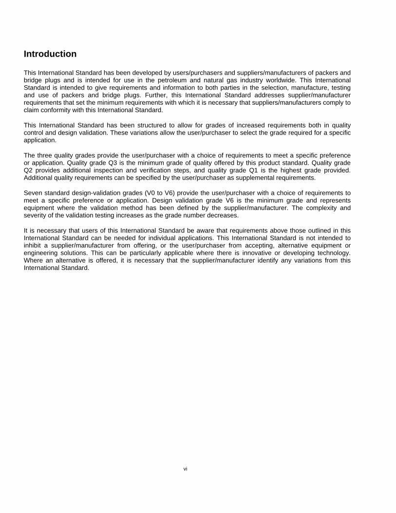
Introduction
This International Standard has been developed by users/purchasers and suppliers/manufacturers of packers and bridge plugs and is intended for use in the petroleum and natural gas industry worldwide. This International Standard is intended to give requirements and information to both parties in the selection, manufacture, testing and use of packers and bridge plugs. Further, this International Standard addresses supplier/manufacturer requirements that set the minimum requirements with which it is necessary that suppliers/manufacturers comply to claim conformity with this International Standard.
This International Standard has been structured to allow for grades of increased requirements both in quality control and design validation. These variations allow the user/purchaser to select the grade required for a specific application.
The three quality grades provide the user/purchaser with a choice of requirements to meet a specific preference or application. Quality grade Q3 is the minimum grade of quality offered by this product standard. Quality grade Q2 provides additional inspection and verification steps, and quality grade Q1 is the highest grade provided. Additional quality requirements can be specified by the user/purchaser as supplemental requirements.
Seven standard design-validation grades (V0 to V6) provide the user/purchaser with a choice of requirements to meet a specific preference or application. Design validation grade V6 is the minimum grade and represents equipment where the validation method has been defined by the supplier/manufacturer. The complexity and severity of the validation testing increases as the grade number decreases.
It is necessary that users of this International Standard be aware that requirements above those outlined in this International Standard can be needed for individual applications. This International Standard is not intended to inhibit a supplier/manufacturer from offering, or the user/purchaser from accepting, alternative equipment or engineering solutions. This can be particularly applicable where there is innovative or developing technology. Where an alternative is offered, it is necessary that the supplier/manufacturer identify any variations from this International Standard.

INTERNATIONAL STANDARD ISO 14310:2008(E)
1
Petroleum and natural gas industries — Downhole equipment — Packers and bridge plugs
1 Scope
This International Standard provides requirements and guidelines for packers and bridge plugs as defined herein for use in the petroleum and natural gas industry. This International Standard provides requirements for the functional specification and technical specification, including design, design verification and validation, materials, documentation and data control, repair, shipment, and storage. In addition, products covered by this International Standard apply only to applications within a conduit. Installation and maintenance of these products are outside the scope of this International Standard.
2 Normative references
The following referenced documents are indispensable for the application of this document. For dated references, only the edition cited applies. For undated references, the latest edition of the referenced document (including any amendments) applies.
ISO 2859-1, Sampling procedures for inspection by attributes — Part 1: Sampling schemes indexed by acceptance quality limit (AQL) for lot-by-lot inspection
ISO 3601-1, Fluid power systems — O-rings — Part 1: Inside diameters, cross-sections, tolerances and designation codes
ISO 3601-3, Fluid power systems — O-rings — Part 3: Quality acceptance criteria
ISO 9000, Quality management systems — Fundamentals and vocabulary
ISO 9712, Non-destructive testing — Qualification and certification of personnel
ISO 11960, Petroleum and natural gas industries — Steel pipes for use as casing or tubing for wells
ISO 15156, (all parts), Petroleum and natural gas industries — Materials for use in H2S-containing environments in oil and gas production
3 Terms and definitions
For the purposes of this document, the terms and definitions given in ISO 9000 and the following apply.
3.1 assembly product comprised of more than one component
3.2 bridge plug mechanical device installed in, and used for blocking fluid (liquid or gas) communication in, the conduit and not installed in a designed receptacle
3.3 casing pipe extending from the surface and intended to line the walls of a drilled well
`` ```` ` ``` ```` ` ` ` ` ` ` ` `

2 PACKERS AND BRIDGE PLUGS
3.4 casing size nominal casing outside diameter (OD) as specified in ISO 11960
3.5 component individual part of an assembly
3.6 conduit casing, tubing or liner, either metallic or non-metallic
3.7 design validation process of proving a design by testing to demonstrate conformity of the product to design requirements
NOTE Seven standard design validation grades (V6 to V0) are specified in 6.5.
[ISO/TS 29001]
3.8 design verification process of examining the result of a given design or development activity to determine conformity with specified requirements
NOTE These activities are described in 6.4.
[ISO/TS 29001]
3.9 drift diameter minimum inside diameter (ID) of a packer, expressed as the OD of the drift bar utilized during assembly inspection, as outlined in 7.4.11
3.10 end connection thread or other mechanism connecting the packer or bridge plug to the conduit
3.11 exposed component flow-wetted component (3.13), internally wetted component (3.18), and/or component contacted by well fluid below the packing element
3.12 extrusion gap radial gap between the maximum rated casing ID and the minimum OD immediately adjacent to the packing element
3.13 flow-wetted component component (3.5) that comes in direct contact with the dynamic movement of well fluids in the flow stream
3.14 gauge OD maximum specified product OD
3.15 grade category or rank given to different requirements for quality or design validation
`` ```` ` ``` ```` ` ` ` ` ` ` ` `

API SPECIFICATION 11D1/ISO 14310 3
3.16 heat-traceable traceable to a unique heat treatment (heat) of material
3.17 inflatable packing element packer or bridge plug packing element energized to form a seal by applying fluid pressure directly to the element
3.18 internally wetted component flow-wetted component (3.13) and any component out of the flow stream, but contacted by well fluids through a port or other passage to the flow-wetted area
3.19 job lot batch of material or components that have undergone the same process or series of processes
3.20 job-lot traceable ⟨parts⟩ identifiable as originating from a job lot that designates the included heat(s)
3.21 liner pipe that does not extend from the surface and is intended to line the walls of a drilled well
3.22 mandrel component(s) of a packer that contain(s) the end connections and provide(s) a conduit through the packer
3.23 manufacturing process and actions performed by an equipment supplier/manufacturer that are necessary to provide finished component(s), assemblies and related documentation that fulfil the requests of the user/purchaser and meet the standards of the supplier/manufacturer
NOTE Manufacturing begins when the supplier/manufacturer receives the order and is completed at the moment the component(s), assemblies and related documentation are surrendered to a transportation provider.
3.24 NACE service packers or bridge plugs whose type 1 components (3.41) are manufactured from materials that comply with ISO 15156 (all parts)
3.25 non-conformance non-fulfilment of a specified requirement
3.26 packer mechanical device with a packing element (3.27), not installed in a designed receptacle, used for blocking fluid (liquid or gas) communication through the annular space between conduits by sealing off the space between them
3.27 packing element seal on a packer (3.26) or bridge plug (3.2) that blocks fluid communication by sealing on the ID of the conduit
`` ```` ` ``` ```` ` ` ` ` ` ` ` `

4 PACKERS AND BRIDGE PLUGS
3.28 performance envelope graph that illustrates the combined effects of differential pressure and axial loads on a packer or bridge plug at the rated temperature
3.29 permanent packer permanent bridge plug bridge plug (3.2) or packer (3.26) that has no design feature for intact removal from the conduit, necessitating substantial destruction for its removal
3.30 pressure reversal change in the direction of the pressure differential across the packing element from above to below or vice versa
3.31 qualified person individual with characteristics or abilities gained through training or experience, or both, as measured against established requirements, such as standards or tests that enable the individual to perform a required function effectively
3.32 repositionable packer repositionable bridge plug bridge plug (3.2) or packer (3.26) that meets the definition of retrievable packer (retrievable bridge plug) (3.33) and has a design feature facilitating its relocation inside the conduit (without removal) while re-establishing its intended function
3.33 retrievable packer retrievable bridge plug bridge plug (3.2) or packer (3.26) that has a design feature facilitating its removal from the conduit substantially intact
3.34 seal device providing a barrier to the passage of liquid and/or gas
3.35 shear device component designed to disconnect under a predetermined load
3.36 standard service packer (3.26) or bridge plug (3.2) whose components might or might not be manufactured from materials that comply with ISO 15156 (all parts)
3.37 substantive design change change to the design, identified by the supplier/manufacturer, that affects the performance of the product in the intended service condition
3.38 temperature-cycle range specified range of temperature fluctuation over which the product is designed to operate
NOTE The temperature-cycle range is applicable anywhere within the product’s temperature range.
`` ```` ` ``` ```` ` ` ` ` ` ` ` `

API SPECIFICATION 11D1/ISO 14310 5
3.39 temperature range specified range of temperature over which the product is designed to operate
3.40 tubing pipe placed within a well to serve as a production or injection conduit
3.41 type 1 component ⟨weld⟩ component that isolates pressure and/or may be loaded in tension as the result of axial loads on the packer or bridge plug during run-in, setting, in situ, or retrieval
3.42 type 2 component ⟨weld⟩ component that does not meet the criteria of a type 1 component (3.41)
4 Symbols and abbreviated terms
AQL Acceptance quality limit
COC Certificate of compliance
ID Inside diameter
MTR Material test report
NDE Non-destructive examination
OD Outside diameter
QC Quality control
5 Functional specification
5.1 General
The user/purchaser shall prepare a functional specification for ordering products that conform to this International Standard and specify the following requirements and operating conditions, as applicable, and/or identify the supplier’s/manufacturer's specific product. These requirements and operating conditions may be conveyed by means of a dimensional drawing, data sheet or other suitable documentation.
5.2 Type description
The user/purchaser shall specify, as applicable, the following type:
⎯ packer or bridge plug;
⎯ permanent, retrievable or repositionable.
5.3 Well parameters
The user/purchaser shall specify, as applicable, the following well parameters:
⎯ dimensions, material, grade of the casing and tubing;
⎯ end connections above/below the packer or bridge plug;
⎯ well angle from the vertical at the setting position of the packer or bridge plug;

6 PACKERS AND BRIDGE PLUGS
⎯ deviations and restrictions through which the packer or bridge plug is required to pass;
⎯ configuration of tubing (single or multiple strings) and other lines (electrical/hydraulic) that are required to pass through or by-pass the packer;
⎯ relationship of packer or bridge plug with other well devices/tubing/casing by means of a well schematic drawing, if applicable;
⎯ expected minimum and maximum values of production/injection pressures, pressure differentials, temperatures, changes in temperatures and flow rates;
⎯ any other relevant well parameter(s).
5.4 Operational parameters
The user/purchaser shall specify, as applicable, any of the following operational parameters:
⎯ installation method, including conveyance method and setting method;
⎯ setting depth;
⎯ retrieving or repositioning method and number of repositionings, if applicable;
⎯ anticipated loading conditions, including combined loading (pressure, tension/compression) and torque, applied to the packer or bridge plug prior to and during setting, during use and during retrieving;
⎯ expected setting temperature and anticipated temperature cycle during well operations;
⎯ size, type and configuration of devices that will be run through the packer, if applicable;
⎯ any other relevant operational parameters.
5.5 Environmental compatibility
5.5.1 General
If the user/purchaser has access to the corrosion property data of the operating environment based on historical data and/or research, he shall state to the supplier/manufacturer which material(s) has/have the ability to perform as required within the corrosion environment per the requirements of 5.5.3, as applicable. Otherwise, material compatibility shall be specified according to 5.5.2.
5.5.2 Well environment
The user/purchaser shall identify the density, chemical/physical composition, and the condition of the fluid and/or its components, including solid (sand production, scale, etc.), liquid and/or gaseous, to which the packer or bridge plug is exposed during its expected life cycle.
5.5.3 Material designation
5.5.3.1 If the user/purchaser chooses to specify materials, the following designations may be used:
⎯ standard service (3.36);
⎯ NACE service (3.24).
5.5.3.2 Material selection may be made for a group of components using the following designations:
⎯ flow-wetted components (3.13);

API SPECIFICATION 11D1/ISO 14310 7
⎯ internally wetted components (3.18);
⎯ exposed components (3.11);
⎯ other components.
5.6 Compatibility with related well equipment
The user/purchaser, where applicable, shall specify the interface connection designs and material requirements, free-passage requirements, and external/internal dimensional limitations necessary to ensure that the product will conform to its expected application. The user/purchaser shall identify, as applicable, the following:
⎯ top and bottom tubular connection(s) and the material and dimensions of the connections to the conduit(s);
⎯ internal receptacle profile(s), bore dimensions(s), outside diameter, inside diameter and the respective locations;
⎯ size, type and configuration of other products and conduits used in connection with this product.
5.7 Design validation
The user/purchaser shall specify the required design validation grade. This International Standard provides seven standard design validation grades (V6 to V0), as defined in 6.5.
5.8 Quality control
The user/purchaser shall specify the required quality grade. This International Standard provides three quality grades (Q3, Q2 and Q1) of quality control, as defined in 7.4.
6 Technical specification
6.1 General
The supplier/manufacturer shall prepare a technical specification that conforms to the requirements defined in the functional specification. If the technical specification does not fully meet the functional requirements, the supplier/manufacturer shall identify the differences to the user/purchaser. The supplier/manufacturer shall also provide the user/purchaser with the product data sheet, as detailed in 7.2.3.
6.2 Technical characteristics
The following criteria shall be met.
⎯ The packer/bridge plug shall locate and seal at the specified location and remain so until intentional intervention defines otherwise. Exceptions to this are the effects of casing failure.
⎯ While located and in service, the packer/bridge plug shall perform in accordance with the functional specification.
⎯ Where applicable, the packer/bridge plug shall not compromise well intervention operations.
6.3 Design requirements
6.3.1 General
Products conforming to this International Standard shall be manufactured to drawings and specifications that are substantially the same as those of the same size, type and model product that was validated.

8 PACKERS AND BRIDGE PLUGS
6.3.2 Design documentation
Design of products manufactured to this International Standard shall include documentation of those designs. This documentation shall include, as applicable, design requirements, assumptions, analysis methods, comparison with previous designs or operating history of similar products, calculations, manufacturing drawings and specifications, design reviews and/or physical testing results (such as design validation testing).
6.3.3 Materials
6.3.3.1 General
Materials (both metallic and non-metallic) and/or the service being provided shall be stated by the supplier/manufacturer and shall be suitable for the class of service and the environment specified in the functional specification. The supplier/manufacturer shall have documented specifications for all materials, and all materials used shall comply with the supplier's/manufacturer's documented specifications.
The user/purchaser may specify materials for the specific use and corrosion environment in the functional specification. If the supplier/manufacturer proposes to use another material, the supplier/manufacturer shall state that this material has performance characteristics suitable for all parameters specified in the well and production/injection parameters.
6.3.3.2 Metals
6.3.3.2.1 Specifications
The supplier's/manufacturer's specifications shall define the following:
a) chemical composition limits;
b) heat treatment conditions;
c) mechanical property limits:
⎯ tensile strength;
⎯ yield strength;
⎯ elongation;
⎯ hardness.
6.3.3.2.2 Mechanical property verification
When required by the quality grade, the mechanical properties for type 1 metal components shall be verified by tests conducted on a material sample produced from the same heat of material. The material sample shall experience the same heat treatment process as the component it qualifies. Material subsequently heat-treated from the same heat of material shall be hardness-tested after processing to confirm compliance with the hardness requirements of the supplier's/manufacturer's specifications. The hardness results shall verify through documented correlation that the mechanical properties of the material tested meet the properties specified. The heat treatment process parameters shall be defined in a heat treatment procedure. Hardness testing is the only mechanical property test required after stress relieving. Material test reports provided by the material supplier/manufacturer are acceptable documentation when validated.
6.3.3.3 Non-metals
The supplier's/manufacturer's documented specifications for non-metallic compounds shall include handling, storage and labelling requirements, including the cure date, batch number, compound identification and shelf life, appropriate to each compound, and shall define those characteristics critical to the performance of the material, such as
a) compound type;

API SPECIFICATION 11D1/ISO 14310 9
b) mechanical properties, as a minimum:
⎯ tensile strength (at break);
⎯ elongation (at break);
⎯ tensile modulus (at 50 % or 100 %, as applicable);
d) compression set;
e) durometer hardness.
6.3.4 Performance rating
The supplier/manufacturer shall state the pressure, temperature and axial performance ratings, as applicable for the products. For packers and bridge plugs validated to grade V4 through grade V0, a rated performance envelope is required.
An example envelope is illustrated in Figure 1. The area within the boundaries defines the rated performance envelope. The lines forming the boundary of the envelope are defined as the maximum operational limits for the packer or bridge plug. Metal mechanical properties over the temperature range shall be considered when determining performance ratings.
Rated performance envelopes shall meet the following criteria.
⎯ The rated performance envelope shall represent the supplier's/manufacturer's maximum ratings.
⎯ “Above” and “below” on the pressure axis are defined as above and below the product and not internal to the product. If the envelope includes ratings based on pressure internal to the product, this shall be specified with the envelope or handled as an additional graph.
⎯ Products with IDs shall be represented with the ID not plugged unless specified with the envelope.
⎯ Shear devices shall be represented at 100 % of their minimum shear value.
⎯ The ratings of the end connections shall not be included.
⎯ The minimum and maximum casing or tubing IDs shall be specified with the envelope. The envelope shall be applicable over this entire specified ID range.
⎯ Axis and sign convention shall be oriented as shown in Figure 1.
⎯ More than one graph may be displayed with the envelope if a legend is included for explanation. For example, various shear device options can be displayed, as shown in Figure 2.
⎯ The product(s) covered by the envelope shall be specified with the envelope.

10 PACKERS AND BRIDGE PLUGS
Key
X1 presure, expressed in megapascals a Above.
X2 pressure, expressed in pounds per square inch b Below.
Y1 force, expressed in decanewtons c Compression.
Y2 force, expressed in pounds d Tensile.
NOTE Points labelled “A” are intersection points of two or more operational limits.
Figure 1 — Example of a rated performance envelope
`` ```` ` ``` ```` ` ` ` ` ` ` ` `

API SPECIFICATION 11D1/ISO 14310 11
Key
X1 presure, expressed in megapascals 3 envelope for 20 000 daN (44 964 lb) shear ring X2 pressure, expressed in pounds per square inch 4 envelope for 25 000 daN (56 205 lb) shear ring Y1 force, expressed in decanewtons a Above. Y2 force, expressed in pounds b Below. 1 envelope for 10 000 daN (22 482 lb) shear ring c Compression. 2 envelope for 15 000 daN (33 723 lb) shear ring d Tensile.
Figure 2 — Example of shear device options
6.4 Design verification
Design verification shall be performed to ensure that each packer and bridge plug design meets the supplier's/manufacturer's technical specifications, including conveyance and removal methods/tools. Design verification includes activities such as design reviews, design calculations, comparison with similar designs and historical records of defined operating conditions. Verification results shall be approved by a qualified person and records of the results shall become a portion of the design documentation.
6.5 Design validation requirements
6.5.1 General
This International Standard specifies seven grades of design validation for which the product shall be supplied. Products shall be supplied to at least the design validation grade specified.
The supplier/manufacturer shall document the validation test procedure and results and shall have on file material specifications and drawings that show all the applicable dimensions and tolerances of parts contained in the validation-tested product. Pre-test and post-test dimensional inspection of critical operational areas, as

12 PACKERS AND BRIDGE PLUGS
determined by the supplier/manufacturer, shall be conducted, documented and maintained by the supplier/manufacturer. Validation test results and dimensional inspection results shall be approved by a qualified person other than the person performing them and records of the results shall become a portion of the design documentation.
The validation grades are the following:
⎯ V6: supplier/manufacturer-defined;
⎯ V5: liquid test;
⎯ V4: liquid test plus axial loads;
⎯ V3: liquid test plus axial loads plus temperature cycling;
⎯ V2: gas test plus axial loads;
⎯ V1: gas test plus axial loads plus temperature cycling;
⎯ V0: gas test plus axial loads plus temperature cycling plus zero bubble acceptance criterion.
Bridge plugs may be run and tested without axial load; however, all validation grades are applicable.
Products qualified to higher grades of design validation may be considered qualified for the lower grades of design validation in accordance with Table 1.
Packers or bridge plugs validated to grade V5 through grade V0 shall not be rated for use in casing or tubing sizes and masses (weights) that can have a maximum ID larger than the ID used in the validation test.
Table 1 — Design validation grade hierarchy
Design validation grade Grades covered
V0 V0, V1, V2, V3, V4, V5 and V6
V1 V1, V2, V3, V4, V5 and V6
V2 V2, V4, V5 and V6
V3 V3, V4, V5 and V6
V4 V4, V5 and V6
V5 V5 and V6
V6 V6
6.5.2 Validation test requirements
6.5.2.1 General
The supplier/manufacturer shall document all parameters and results of the evaluations that demonstrate conformance to the validation grade. Test data shall identify the leak rate for the duration of the subject test. If no leakage occurred, this shall be clearly stated.
6.5.2.2 Grade V6 — Supplier/manufacturer-defined
The supplier/manufacturer defines the validation method and acceptance criteria.
`` ```` ` ``` ```` ` ` ` ` ` ` ` `

API SPECIFICATION 11D1/ISO 14310 13
6.5.2.3 Grade V5 — Liquid test
The supplier/manufacturer shall adhere to the following test parameters and criteria for conformance to this validation grade.
⎯ Set in maximum rated casing or tubing ID ± 0.76 mm (± 0.030 in) (see 6.5.1).
⎯ Set with the minimum rated setting force or pressure (± 10 %).
⎯ Test products with inflatable packing elements horizontally. Centralization at one end of the test fixture is acceptable.
⎯ Products with no anchoring devices or anchoring devices that hold in one direction may be restrained by the test fixture to prevent movement in the un-anchored direction(s).
⎯ Set and run entire test at or above maximum rated temperature.
⎯ Test at or above maximum rated differential pressure.
⎯ Perform a minimum of two pressure reversals at or above maximum rated pressure from above to below or vice versa.
⎯ Use a liquid test medium of water, with or without additives, or hydraulic oil. The density shall be less than 1 100 kg/m3 (68.67 lb/ft3). Liquid shall be visibly free from particulate matter or other material that can plug a small leak.
⎯ Maintain a minimum hold period of 15 min for pressure tests.
⎯ Acceptance criterion: no more than 1 % reduction in the maximum rated differential pressure over the hold period after sufficient time has been allowed for stabilization. Time period for stabilization is at the discretion of the supplier/manufacturer.
⎯ Use the supplier's/manufacturer's specified methods to remove the retrievable-type packers/bridge plugs at the end of the test.
6.5.2.4 Grade V4 — Liquid plus axial load test
The supplier/manufacturer shall adhere to the following test parameters and criteria for conformance to this validation grade.
⎯ Set in maximum rated casing or tubing ID ± 0.76 mm (± 0.030 in) (see 6.5.1).
⎯ Set with the minimum rated setting force or pressure (± 10 %).
⎯ Test products with inflatable packing elements horizontally. Centralization at one end of the test fixture is acceptable.
⎯ Products with no anchoring devices or anchoring devices that hold in one direction may be restrained by the test fixture to prevent movement in the un-anchored direction(s).
⎯ Set and run the entire test at or above the maximum rated temperature.
⎯ Test at or above the maximum rated differential pressure.
⎯ Perform a minimum of two pressure reversals at or above the maximum rated pressure from above to below or vice versa.
⎯ Test to all intersection points of the rated performance envelope.
`` ```` ` ``` ```` ` ` ` ` ` ` ` `
14 PACKERS AND BRIDGE PLUGS
⎯ Test those packers or bridge plugs having shear-release features at their maximum rated shear load. For safety, the shear device can be replaced with a stronger shear device that can adequately withstand the maximum shear load.
⎯ Use a liquid test medium of water, with or without additives, or hydraulic oil. The density shall be less than 1 100 kg/m3 (68.67 lb/ft3). Liquid shall be visibly free from particulate matter or other material that can plug a small leak.
⎯ Maintain a minimum hold period of 15 min for pressure tests.
⎯ Acceptance criterion: no more than 1 % reduction in the maximum rated differential pressure over the hold period after sufficient time has been allowed for stabilization. The time period for stabilization is at the discretion of the supplier/manufacturer.
⎯ Use the supplier's/manufacturer's specified methods to remove the retrievable-type packers/bridge plugs at the end of the test.
6.5.2.5 Grade V3 — Liquid plus axial loads plus temperature cycling test
The supplier/manufacturer shall adhere to the following test parameters and criteria for conformance to this validation grade.
⎯ Set in maximum rated casing or tubing ID ± 0.76 mm (± 0.030 in) (see 6.5.1).
⎯ Set with the minimum rated setting force or pressure (± 10 %).
⎯ Test products with inflatable packing elements horizontally. Centralization at one end of the test fixture is acceptable.
⎯ Products with no anchoring devices or anchoring devices that hold in one direction may be restrained by the test fixture to prevent movement in the un-anchored direction(s).
⎯ Set and run the entire test, except temperature cycling, at or above the maximum rated temperature.
⎯ Test at or above the maximum rated differential pressure.
⎯ Perform a minimum of two pressure reversals at or above the maximum rated pressure from above to below or vice versa.
⎯ Test to all intersection points of the rated performance envelope.
⎯ Test those packers or bridge plugs having shear-release features at their maximum rated shear load. For safety, the shear device can be replaced with a stronger shear device that can adequately withstand the maximum shear load.
⎯ Test a minimum of one temperature cycle. Start the temperature cycle at or above the maximum rated temperature and cool down by at least the maximum rated temperature-cycle range. A pressure hold is required at the low end of the temperature-cycle range and after heating back up to the maximum rated temperature.
⎯ Use a liquid test medium of water, with or without additives, or hydraulic oil. The density shall be less than 1 100 kg/m3 (68.67 lb/ft3). Liquid shall be visibly free from particulate matter or other material that can plug a small leak.
⎯ Maintain a minimum hold period of 15 min for pressure tests.
⎯ Acceptance criterion: no more than 1 % reduction in the maximum rated differential pressure over the hold period after sufficient time has been allowed for stabilization. The time period for stabilization is at the discretion of the supplier/manufacturer.
`` ```` ` ``` ```` ` ` ` ` ` ` ` `
API SPECIFICATION 11D1/ISO 14310 15
⎯ Use the supplier's/manufacturer's specified methods to remove the retrievable-type packers/bridge plugs at the end of the test.
6.5.2.6 Grade V2 — Gas plus axial load test
The supplier/manufacturer shall adhere to the following test parameters and criteria for conformance to this validation grade.
⎯ Set in maximum rated casing or tubing ID ± 0.76 mm (± 0.030 in) (see 6.5.1).
⎯ Set with the minimum rated setting force or pressure (± 10 %).
⎯ Test products with inflatable packing elements horizontally. Centralization at one end of the test fixture is acceptable.
⎯ Products with no anchoring devices or anchoring devices that hold in one direction may be restrained by the test fixture to prevent movement in the un-anchored direction(s).
⎯ Set and run the entire test at or above the maximum rated temperature.
⎯ Test at or above the maximum rated differential pressure.
⎯ Perform a minimum of two pressure reversals at or above the maximum rated pressure from above to below or vice versa.
⎯ Test to all intersection points of the rated performance envelope.
⎯ Test those packers or bridge plugs having shear-release features at their maximum rated shear load. For safety, the shear device can be replaced with a stronger shear device that can adequately withstand the maximum shear load.
⎯ Use a gas test medium of air, nitrogen or other gas or mixture of gases.
⎯ Maintain a minimum hold period of 15 min for pressure tests.
⎯ Acceptance criterion: no more than 20 cm3 of gas accumulated in a graduated cylinder over the hold period after sufficient time has been allowed for stabilization. The time period for stabilization is at the discretion of the supplier/manufacturer. The bubble rate shall not increase during the hold period. Graduated cylinders for accumulated gas shall be at atmospheric pressure.
⎯ Use the supplier's/manufacturer's specified methods to retrieve the retrievable packers/bridge plugs at the end of the test.
6.5.2.7 Grade V1 — Gas plus axial loads plus temperature cycling test
The supplier/manufacturer shall adhere to the following test parameters and criteria for conformance to this validation grade.
⎯ Set in maximum rated casing or tubing ID ± 0.76 mm (± 0.030 in) (see 6.5.1).
⎯ Set with the minimum rated setting force or pressure (± 10 %).
⎯ Test products with inflatable packing elements horizontally. Centralization at one end of the test fixture is acceptable.
⎯ Products with no anchoring devices or anchoring devices that hold in one direction may be restrained by the test fixture to prevent movement in the un-anchored direction(s).
⎯ Set and run the entire test, except temperature cycling, at or above the maximum rated temperature.
`` ```` ` ``` ```` ` ` ` ` ` ` ` `
16 PACKERS AND BRIDGE PLUGS
⎯ Test at or above the maximum rated differential pressure.
⎯ Perform a minimum of two pressure reversals at or above the maximum rated pressure from above to below or vice versa.
⎯ Test to all intersection points of the rated performance envelope.
⎯ Test those packers or bridge plugs having shear-release features at their maximum rated shear load. For safety, the shear device can be replaced with a stronger shear device that can adequately withstand the maximum shear load.
⎯ Test a minimum of one temperature cycle. Start the temperature cycle at or above the maximum rated temperature and cool down by at least the maximum rated temperature-cycle range. A pressure hold is required at the low end of the temperature-cycle range and after heating back up to the maximum rated temperature.
⎯ Use a gas test medium of air, nitrogen, or other gas or mixture of gases.
⎯ Maintain a minimum hold period of 15 min for pressure tests.
⎯ Acceptance criterion: no more than 20 cm3 of gas accumulated in a graduated cylinder over the hold period after sufficient time has been allowed for stabilization. The time period for stabilization is at the discretion of the supplier/manufacturer. The bubble rate shall not increase during the hold period. Graduated cylinders for accumulated gas shall be at atmospheric pressure.
⎯ Use the supplier's/manufacturer's specified methods to remove the retrievable-type packers/bridge plugs at the end of the test.
6.5.2.8 Grade V0 — Gas plus axial loads plus temperature-cycling test plus zero-bubble acceptance criterion
The supplier/manufacturer shall adhere to the following test parameters and critera for conformance to this validation grade.
⎯ Set in maximum rated casing or tubing ID ± 0.76 mm (± 0.030 in) (see 6.5.1).
⎯ Set with the minimum rated setting force or pressure (± 10 %).
⎯ Test products with inflatable packing elements horizontally. Centralization at one end of the test fixture is acceptable.
⎯ Products with no anchoring devices or anchoring devices that hold in one direction may be restrained by the test fixture to prevent movement in the un-anchored direction(s).
⎯ Set and run the entire test, except temperature cycling, at or above the maximum rated temperature.
⎯ Test at or above the maximum rated differential pressure.
⎯ Perform a minimum of two pressure reversals at or above the maximum rated pressure from above to below or vice versa.
⎯ Test to all intersection points of the rated performance envelope.
⎯ Test those packers or bridge plugs having shear-release features at their maximum rated shear load. For safety, the shear device can be replaced with a stronger shear device that can adequately withstand the maximum shear load.
⎯ Test a minimum of one temperature cycle. Start the temperature cycle at or above the maximum rated temperature and cool down by at least the maximum rated temperature-cycle range. A pressure hold is required at the low end of the temperature-cycle range and after heating back up to the maximum rated temperature.

API SPECIFICATION 11D1/ISO 14310 17
⎯ Use a gas test medium of air, nitrogen, or other gas or mixture of gases.
⎯ Maintain a minimum hold period of 15 min for pressure tests.
⎯ Acceptance criterion: zero bubbles of gas accumulated in a graduated cylinder over the hold period after sufficient time has been allowed for stabilization. The time period for stabilization is at the discretion of the supplier/manufacturer. Graduated cylinders for accumulated gas shall be at atmospheric pressure.
⎯ Use the supplier's/manufacturer's specified methods to remove the retrievable-type packers/bridge plugs at the end of the test.
6.6 Design changes
All design changes shall be documented and reviewed against the design verification and design validation to determine if the change is a substantive change (see 3.37). A design that undergoes a substantive change becomes a new design requiring design verification as specified in 6.4 and design validation as specified in 6.5. Design changes identified as non-substantive shall include documented justification.
The supplier/manufacturer shall, as a minimum, consider the following:
⎯ stress levels of the modified or changed components;
⎯ material changes;
⎯ functional changes.
Changes to a component or series of components may be identified as a substantive change and require design validation. This may be done by testing only the component or series of components rather than the entire assembly. The test shall adequately simulate the loading conditions that would be present if the entire assembly were tested. The supplier/manufacturer shall document the detailed test results and analysis that demonstrate that the component test adequately simulates the required loading conditions. Evaluation results shall be approved by a qualified person (see 3.31) other than the person performing them, and records of the results shall become a portion of the design documentation.
6.7 Design validation by scaling
6.7.1 General
Within the same casing size or tubing size, scaling may be used to validate variations in a product family in accordance with the requirements and limitations of 6.7.2 and 6.7.3. This applies to products validated to grade V5 through grade V0 in accordance with 6.5.
6.7.2 Product family for scaling
A product family is a group of assemblies that meets the following design requirements:
⎯ configuration: the design principles for the geometry, materials and functionality are the same;
⎯ design stress levels: the design stress levels in relation to material mechanical properties are based on the same criteria.
6.7.3 Limitations of scaling
Scaling is allowed to validate a product family within a given casing or tubing size with the following limitations.
⎯ A validation test shall be run on the product with the largest extrusion gap (see 3.12).
⎯ A validation test shall be run on the product(s) with the thinnest and thickest cross-section packing element(s).
`` ```` ` ``` ```` ` ` ` ` ` ` ` `

18 PACKERS AND BRIDGE PLUGS
⎯ Packing elements and anti-extrusion components shall be of the same geometry and materials as the tested product.
⎯ The ID of the packing element(s) and OD of the component under the packing element(s) shall be the same as the tested product.
⎯ Scaling shall not be used to cover products with higher pressure ratings, a higher temperature range, a larger temperature cycle range, higher axial load ratings or larger rating envelopes than the tested product.
6.8 Other validations
Repositionable packers and bridge plugs shall undergo supplemental validation testing that includes resetting and testing in accordance with the requirements and acceptance criteria of the supplier/manufacturer.
6.9 Assembly verification
Each packer and bridge plug assembly shall be verified in accordance with 7.4.11.
7 Supplier's/manufacturer's requirements
7.1 General
Clause 7 contains the detailed requirements necessary to verify that each product manufactured meets the requirements of the functional and technical specifications. These include requirements for documentation and data control, product identification, quality control, functional testing, repair, redress, shipping and storage.
7.2 Documentation and data control
7.2.1 General
The supplier/manufacturer shall establish and maintain documented procedures to control all documents and data that relate to the requirements of this International Standard. These documents and data shall be maintained to demonstrate conformance to specified requirements. All documents and data shall be legible and shall be stored and retained in such a way that they are readily retrievable in facilities that provide a suitable environment to prevent damage or deterioration and to prevent loss. Documents and data may be in any form or type of media, such as hard copy or electronic media. All documents and data shall be available to, and auditable by, the user/purchaser.
All documentation and data associated with design verification, design validation and design change justification shall be maintained for ten years after the date of last manufacture.
Quality-control documentation includes all documents and data necessary to demonstrate conformance to 7.4.1 through 7.4.15. Quality-control documentation shall be retained by the supplier/manufacturer for a minimum of five years from date of manufacture. These shall be available to and auditable by the user/purchaser.
7.2.2 Operating manual
An operating manual shall be available for all products supplied in accordance with this International Standard.
Operating manuals shall contain at least the following information:
⎯ manual reference number;
⎯ operational procedures and related tools;
⎯ pre-installation inspection procedures;
⎯ storage recommendations;
API SPECIFICATION 11D1/ISO 14310 19
⎯ a representative drawing showing major dimensions (ODs, IDs and lengths);
⎯ special precautions and handling.
7.2.3 Product data sheet
Product data sheets shall be supplied at delivery to the user/purchaser, as required in 6.1, and shall contain at least the following information, where applicable:
⎯ name and address of supplier/manufacturer;
⎯ manufacturer product number;
⎯ manufacturer product name;
⎯ product type;
⎯ product characteristics;
⎯ service provided;
⎯ metallic materials;
⎯ non-metallic materials;
⎯ drift diameter;
⎯ gauge OD;
⎯ overall length;
⎯ temperature range;
⎯ temperature cycle range for V3, V1, and V0;
⎯ rated performance envelope for V4 through V0;
⎯ pressure rating for V6 and V5;
⎯ top connection(s);
⎯ bottom connection(s);
⎯ casing or tubing range, size and mass and/or minimum and maximum casing or tubing IDs;
⎯ conveyance method;
⎯ maximum conveyance OD, inclusive of running/repositioning equipment, as applicable;
⎯ setting method, including minimum (maximum, as applicable) setting force/pressure;
⎯ retrieval method (if retrievable);
⎯ repositioning method (if repositionable);
⎯ quality grade;
⎯ design validation grade;

20 PACKERS AND BRIDGE PLUGS
⎯ operating manual reference number.
7.3 Product identification
Each product furnished to this International Standard shall be permanently identified according to the supplier's/manufacturer's specifications. The supplier's/manufacturer’s specifications shall define the type, method of application and location of the identifications. The following information shall be included as a minimum:
⎯ manufacturer's identification;
⎯ manufacturer's product number;
⎯ date of manufacture (month/year);
⎯ quality grade;
⎯ design validation grade;
⎯ for quality grade Q1, a unique serial and traceability number.
7.4 Quality control
7.4.1 General
This International Standard specifies three quality grades, Q1, Q2 and Q3, to which the product shall be supplied. Products shall be supplied to at least the quality control grade specified. Quality-control requirements are detailed in 7.4.2 through 7.4.15 and summarized in Table 2. Where there are no requirements listed in 7.4.2 through 7.4.15, the word “None“ appears in Table 2.
7.4.2 Material
Material, metallic or non-metallic, used in the manufacture of components shall meet one of the following requirements:
⎯ COC to the supplier/manufacturer stating that the material meets the supplier's/manufacturer's documented specifications, or
⎯ MTR to the supplier/manufacturer so that the supplier/manufacturer can verify that the material meets the supplier's/manufacturer's documented specifications.
The supplier/manufacturer shall verify, through testing, that the chemical/mechanical properties of metallic materials meet the MTRs as specified for quality grade Q1 for type 1 components. Chemical/mechanical property determination shall be in accordance with a national standard or International Standard.
7.4.3 Castings
The casting subcontractor or supplier shall provide a COC to the supplier/manufacturer stating that the casting meets the supplier's/manufacturer's documented specifications.

API SPECIFICATION 11D1/ISO 14310 21
Table 2 — Summary of quality requirements
Item Quality grade a
Q3 Q2 Q1
Metallic material COC or MTR COC or MTR Verify MTR for type 1 components
COC or MTR for type 2 components
Non-metallic material COC or MTR COC or MTR COC or MTR
Castings COC COC COC
Heat treatment COC (subcontractor) Job-lot verification
(supplier/manufacturer)
COC (subcontractor) Job-lot verification
(supplier/manufacturer)
COC (subcontractor) Job-lot verification
(supplier/manufacturer) Heat treat certificate for
type 1 components
Component traceability Job-lot traceable for type 1 components
Job-lot traceable for type 1 components
Heat traceable for type 1 components
Component dimensions Sampling plan Sampling plan 100 % for type 1 components
Welding
Type 1 welds Visual Surface NDE per sampling plan and visual
Surface NDE 100 % and visual
Type 2 welds Visual Visual Visual
Hardness
Type 1 components None Sampling plan 100 %
Type 2 components None None None
Component NDE
Type 1 components None Surface NDE per sampling plan
Surface NDE 100 %
Type 2 components None None Visual
Shear devices Shear verification Shear verification Shear verification
Assembly verification None Functional test ID drift
Functional test ID drift
OD dimensional Torque documentation
Assembly traceability None None Assembly serialization
QC documentation Supplier/manufacturer retained
Supplier/manufacturer retained
Supplier/manufacturer retained
a “None” indicates that there are no requirements listed in 7.4.2 through 7.4.15.
7.4.4 Heat treatment
7.4.4.1 General
Heat treatment of components or raw material shall meet the following requirements.
⎯ Heat treating shall be performed with heat-treating equipment that has been calibrated and surveyed.

22 PACKERS AND BRIDGE PLUGS
⎯ If heat treatment is performed by a subcontractor, the subcontractor shall provide a COC to the supplier/manufacturer stating that the heat treatment meets the supplier’s/manufacturer's documented specifications.
⎯ If heat treatment is performed by the supplier/manufacturer, heat treatment shall comply with the supplier's/manufacturer's documented specifications.
⎯ For type 1 components, a heat treatment certificate showing actual times and temperatures is required for quality grade Q1.
7.4.4.2 Heat-treating equipment qualification
7.4.4.2.1 Furnace calibration
Furnace calibration shall meet the following requirements.
a) Each furnace shall be surveyed within one year prior to heat-treating operations. When a furnace is repaired or rebuilt, a new survey shall be required before heat treating.
b) Batch-type and continuous-type heat-treating furnaces shall be calibrated in accordance with one of the following procedures:
⎯ procedures specified in an International Standard or national standard, such as SAE AMS-H-6875A,
⎯ procedures specified in an International Standard or national standard, such as BS 2M 54,
⎯ manufacturer's documented specifications, including acceptance criteria that are not less stringent than the procedures identified above.
7.4.4.2.2 Instrumentation
Instrumentation shall meet the following requirements.
⎯ Automatic controlling and recording instruments shall be used.
⎯ Thermocouples shall be located in the furnace working zone(s) and protected from furnace atmospheres.
⎯ The controlling and recording instruments used for the heat treatment processes shall have an accuracy of ± 1 % of their full-scale range.
⎯ Temperature-controlling and -recording instruments shall be calibrated at least once every three months until a documented calibration history can be established. Calibration intervals shall then be established based on repeatability, degree of usage and documented calibration history.
⎯ Equipment used to calibrate the production equipment shall have an accuracy of ± 0.25 % of the full-scale range.
7.4.5 Component traceability
Component traceability shall meet the following requirements.
⎯ Type 1 components shall be job-lot traceable for quality grades Q2 and Q3.
⎯ Type 1 components shall be heat-traceable for quality grade Q1.
⎯ Components that are castings, or are manufactured from castings, shall be excluded from traceability for grades Q3 and Q2.
`` ```` ` ``` ```` ` ` ` ` ` ` ` `
API SPECIFICATION 11D1/ISO 14310 23
7.4.6 Component dimensional inspection
Component dimensional inspection shall be performed and shall meet the following requirements.
⎯ Thread tolerances, inspection requirements, gauges, gauging practice, gauge calibration and certification shall conform to the specified thread-manufacturer's documented specifications.
⎯ Dimensional tolerances of O-rings shall be in accordance with ISO 3601-1 or equivalent. Other packing elements shall meet dimensional tolerances of the supplier's/manufacturer's documented specifications.
⎯ Type 2 components and all type 1 components for quality grades Q2 and Q3 shall be dimensionally inspected per a sampling plan that meets the requirements of an International Standard or national standard, such as ISO 2859-1 or ANSI/ASQC Z1.4.
⎯ Type 1 components shall be 100 % dimensionally inspected for quality grade Q1.
7.4.7 Welds
Welds shall meet the following requirements.
⎯ Type 1 welds (see 3.41) shall meet the requirements of an International Standard or national standard such as ASME Boiler and Pressure Vessel Code, Section IX.
⎯ Each welded component shall be stress-relieved as specified in the supplier's/manufacturer's documented specifications that include acceptance criteria.
7.4.8 Hardness inspection of components
Hardness inspection of components shall meet the following requirements.
⎯ Type 1 components for quality grade Q2 shall be hardness-inspected per a sampling plan that meets the requirements of an International Standard or national standard, such as ISO 2859-1 or ANSI/ASQC Z1.4.
⎯ 100 % of type 1 components for quality grade Q1 shall be hardness inspected.
⎯ Type 2 components do not require hardness inspection.
⎯ Hardness inspection of metallic components shall meet the requirements of an International Standard or national standard, such as ISO 6506-1, ISO 6507-1 or ISO 6508-1.
⎯ The durometer hardness of O-rings or other elastomeric packing elements shall be determined in accordance with an International Standard or national standard, such as ASTM D2240 or ASTM D1415. A test specimen manufactured from each batch may be used.
7.4.9 NDE of components/welds
NDE of components and welds shall meet the following requirements.
⎯ Welds shall be visually inspected per the requirements of an International Standard or national standard, such as the ASME Boiler and Pressure Vessel Code, Section V, Article 9.
⎯ NDE for non-metallic components shall be visual inspection per supplier's/manufacturer's documented specifications.
⎯ NDE for metallic components shall be magnetic-particle inspection or liquid-penetrant inspection.
⎯ Sampling procedures and the criteria for acceptance or rejection of a batch lot shall be in accordance with ISO 2859-1, general inspection level II, at a 2.5 AQL for O-Rings and a 1.5 AQL for other packing elements, until a documented variation history can be established. Sampling procedures shall then be established based on the documented variation history.

24 PACKERS AND BRIDGE PLUGS
⎯ Visual inspection of O-rings shall be in accordance with ISO 3601-3 or equivalent. Other packing elements shall be visually inspected in accordance with the supplier's/manufacturer's documented specifications.
⎯ Magnetic-particle inspection shall meet the requirements of an International Standard or national standard, such as ISO 13665 or ASTM E709.
⎯ Liquid-penetrant inspection shall meet the requirements of an International Standard or national standard, such as ISO 12095 or ASTM E165.
⎯ NDE acceptance criteria shall be according to the supplier's/manufacturer's documented specifications.
⎯ All NDE instructions shall be approved by a level III examiner qualified in accordance with ISO 9712.
NOTE For the purposes of these provisions, ASNT RP SNT-TC-1A is equivalent to ISO 9712.
⎯ Type 1 components and welds for quality grade Q2 shall be NDE-inspected per a sampling plan that meets the requirements of an International Standard or national standard, such as ISO 2859-1 or ANSI/ASQC Z1.4.
⎯ Type 1 components and welds for quality grade Q1 shall be 100 % NDE-inspected using liquid-penetrant or magnetic particles.
⎯ Type 2 components for quality grade Q1 shall be visually inspected per the supplier's/manufacturer's documented specifications.
7.4.10 Shear device verification
At least one shear device per heat lot shall be sheared in accordance with the supplier's/manufacturer's documented procedure to verify that the shear value meets the supplier's/manufacturer's documented specification.
7.4.11 Assembly verification
Assembly verification shall meet the following requirements.
⎯ For quality grades Q2 and Q1, a low-pressure, internal test shall be performed on each packer by plugging the end connection(s) (see 3.10) and pressurizing to a minimum of 350 kPa (approximately 50 psi) using either liquid or gas as the test medium. One-piece mandrels or mandrels with only internal metal-to-metal sealing connections are excluded from this requirement. Test duration and acceptance criteria shall be defined by the supplier's/manufacturer's documented procedures. Functional test data shall be recorded, dated and signed by the qualified person performing the tests.
⎯ For quality grades Q2 and Q1, ID drift each packer per the supplier's/manufacturer's documented specifications. ID drift shall apply only to packer IDs not designed as sealing surfaces (sealbores). Drift-bar diameter shall match the rated drift diameter of the packer. Drift-bar dimensions shall meet the requirements specified in ISO 11960.
⎯ For quality grade Q1, the OD shall be inspected according to the supplier's/manufacturer's documented specifications. OD dimensional inspection shall verify that the entire OD of the assembly is less than, or equal to, the maximum specified OD.
⎯ For quality grade Q1, actual torque values for all metal-to-metal sealing connections shall be recorded and verified to be within the supplier's/manufacturer's documented specifications. End connections are specifically excluded from this requirement.
7.4.12 Assembly traceability
Assembly serialization shall be used to provide traceability of all type 1 components within each assembly for quality grade Q1.

API SPECIFICATION 11D1/ISO 14310 25
7.4.13 Manufacturing non-conformance
The supplier/manufacturer shall establish and maintain documented procedures to ensure that an assembly or component that does not conform to specified requirements is prevented from unintended use or installation. This control shall provide for identification, documentation, evaluation, segregation (when applicable) and disposition of non-conforming assemblies or components.
The responsibility for review and authority for the disposition of non-conforming assemblies or components shall be defined by the supplier/manufacturer. Non-conforming assemblies or components may be
⎯ reworked to meet the specified requirements,
⎯ accepted with or without repair by concession, or
⎯ rejected or scrapped.
Repaired and/or reworked assemblies or components shall be inspected in accordance with the requirements of the appropriate quality grade and the documented specifications of the supplier/manufacturer.
7.4.14 Calibration systems
Measuring and testing equipment used for acceptance shall be identified, controlled, calibrated and adjusted at specific intervals in accordance with an internationally recognized International Standard, such as ISO/IEC 17025.
Technologies for measuring and testing equipment with verifiable accuracies equal to, or better than, those listed in this International Standard may be applied with appropriate documentation and when approved by a qualified person.
Pressure-measuring devices shall be
⎯ readable to at least ± 0.5 % of the full-scale range or less, as required to perform the specified measurement,
⎯ calibrated to maintain ± 2 % accuracy of the full-scale range or less, as required to perform the specified measurement(s),
⎯ used only within the calibrated range,
⎯ calibrated with a master pressure-measuring device or a dead-weight tester.
Calibration intervals for pressure-measuring devices shall be a maximum of three months until a documented calibration history can be established. Calibration intervals shall then be established based on repeatability, degree of usage and documented calibration history.
7.4.15 Personal qualifications
Personnel performing NDE shall be qualified in accordance with an International Standard or national standard, such as ISO 9712, level 2 minimum, for evaluation and interpretation.
Personnel performing visual examinations shall have an annual eye examination in accordance with an International Standard or national standard such as ISO 9712, as applicable to the discipline to be performed.
All other personnel performing inspection for acceptance shall be qualified per the supplier's/manufacturer's documented specifications.
8 Repair
Repair activities to packers and bridge plugs shall return the product to a condition meeting all requirements stated in this International Standard or the edition in effect at the time of original manufacture.

26 PACKERS AND BRIDGE PLUGS
9 Shipment/storage
Packers and bridge plugs shall be stored per the documented specifications of the supplier/manufacturer to prevent deterioration (for example caused by atmospheric conditions, debris, radiation, etc.) prior to transport.
Packers and bridge plugs shall be packaged for transport per the documented specifications of the supplier/manufacturer to prevent normal handling loads and contamination from harming the equipment. These specifications shall address the protection of external sealing elements, sealing surfaces and exposed threaded connections.
`` ```` ` ``` ```` ` ` ` ` ` ` ` `

27
Annex A
(informative)
Use of the API Monogram by Licensees
A.1 Scope
The API Monogram Program allows an API Licensee to apply the API Monogram to products. The API Monogram Program delivers significant value to the international oil and gas industry by linking the verification of an organization's quality management system with the demonstrated ability to meet specific product specification requirements. The use of the Monogram on products constitutes a representation and warranty by the Licensee to purchasers of the products that, on the date indicated, the products were produced in accordance with a verified quality management system and in accordance with an API product specification.
When used in conjunction with the requirements of the API License Agreement, API Q1, in its entirety, defines the requirements for those organizations who wish to voluntarily obtain an API license to provide API monogrammed products in accordance with an API product specification.
API Monogram Program licenses are issued only after an on-site audit has verified that the Licensee conforms to the requirements described in API Q1 in total, and the requirements of an API product specification. Customers/users are requested to report to API all problems with API monogrammed products. The effectiveness of the API Monogram Program can be strengthened by customers/users reporting problems encountered with API monogrammed products. A nonconformance may be reported using the API Nonconformance Reporting System available at https://ncr.api.org. API solicits information on new product that is found to be nonconforming with API-specified requirements, as well as field failures (or malfunctions), which are judged to be caused by either specification deficiencies or nonconformities with API-specified requirements.
This annex sets forth the API Monogram Program requirements necessary for a supplier to consistently produce products in accordance with API-specified requirements. For information on becoming an API Monogram Licensee, please contact API, Certification Programs, 1220 L Street, NW, Washington, DC 20005 or call 202-962-4791 or by email at [email protected].
A.2 References
In addition to the referenced standards listed earlier in this document, this annex references the following standard:
API Specification Q1.
For Licensees under the Monogram Program, the latest version of this document shall be used. The requirements identified therein are mandatory.
A.3 API Monogram Program: Licensee Responsibilities
A.3.1 Maintaining a License to Use the API Monogram
For all organizations desiring to acquire and maintain a license to use the API Monogram, conformance with the following shall be required at all times:
a) the quality management system requirements of API Q1;
b) the API Monogram Program requirements of API Q1, Annex A;

28 PACKERS AND BRIDGE PLUGS
c) the requirements contained in the API product specification(s) for which the organization desires to be licensed;
d) the requirements contained in the API Monogram Program License Agreement.
A.3.2 Monogrammed Product⎯Conformance with API Q1
When an API-licensed organization is providing an API monogrammed product, conformance with API-specified requirements, described in API Q1, including Annex A, is required.
A.3.3 Application of the API Monogram
Each Licensee shall control the application of the API Monogram in accordance with the following.
a) Each Licensee shall develop and maintain an API Monogram marking procedure that documents the marking/monogramming requirements specified by the API product specification to be used for application of the API Monogram by the Licensee. The marking procedure shall define the location(s) where the Licensee shall apply the API Monogram and require that the Licensee's license number and date of manufacture be marked on monogrammed products in conjunction with the API Monogram. At a minimum, the date of manufacture shall be two digits representing the month and two digits representing the year (e.g. 05-07 for May 2007) unless otherwise stipulated in the applicable API product specification. Where there are no API product specification marking requirements, the Licensee shall define the location(s) where this information is applied.
b) The API Monogram may be applied at any time appropriate during the production process but shall be removed in accordance with the Licensee’s API Monogram marking procedure if the product is subsequently found to be nonconforming with API-specified requirements. Products that do not conform to API-specified requirements shall not bear the API Monogram.
c) Only an API Licensee may apply the API Monogram and its license number to API monogrammable products. For certain manufacturing processes or types of products, alternative API Monogram marking procedures may be acceptable. The current API requirements for Monogram marking are detailed in the API Policy Document, Monogram Marking Requirements, available on the API Monogram Program website at http://www.api.org/certifications/monogram/.
d) The API Monogram shall be applied at the licensed facility.
e) The authority responsible for applying and removing the API Monogram shall be defined in the Licensee’s API Monogram marking procedure.
A.3.4 Records
Records required by API product specifications shall be retained for a minimum of five years or for the period of time specified within the product specification if greater than five years. Records specified to demonstrate achievement of the effective operation of the quality system shall be maintained for a minimum of five years.
A.3.5 Quality Program Changes
Any proposed change to the Licensee’s quality program to a degree requiring changes to the quality manual shall be submitted to API for acceptance prior to incorporation into the Licensee's quality program.
A.3.6 Use of the API Monogram in Advertising
Licensee shall not use the API Monogram on letterheads or in any advertising (including company-sponsored web sites) without an express statement of fact describing the scope of Licensee’s authorization (license number). The Licensee should contact API for guidance on the use of the API Monogram other than on products.

API SPECIFICATION 11D1/ISO 14310 29
A.4 Marking Requirements for Products
A.4.1 General
These marking requirements apply only to those API Licensees wishing to mark their products with the API Monogram.
A.4.2 Product Specification Identification
Manufacturers shall mark equipment with the information identified in 7.3, as a minimum, including “API Spec 11D1.”
API Spec 11D1 shall be marked in addition to, or in lieu of, the designation ISO 14310.
A.4.3 Units
As a minimum, equipment should be marked with U.S. customary (USC) units. Use of dual units [metric (SI) units and USC units] is acceptable.
A.4.4 License Number
The API Monogram license number shall not be used unless it is marked in conjunction with the API Monogram.
A.5 API Monogram Program: API Responsibilities
The API shall maintain records of reported problems encountered with API monogrammed products. Documented cases of nonconformity with API-specified requirements may be reason for an audit of the Licensee involved (also known as audit for “cause”).
Documented cases of specification deficiencies shall be reported, without reference to Licensees, customers or users, to API Subcommittee 18 (Quality) and to the applicable API Standards Subcommittee for corrective actions.
`` ```` ` ``` ```` ` ` ` ` ` ` ` `

30
Bibliography
[1] ISO 6506-1, Metallic materials — Brinell hardness test — Part 1: Test method
[2] ISO 6507-1, Metallic materials — Vickers hardness test — Part 1: Test method
[3] ISO 6508-1, Metallic materials — Rockwell hardness test — Part 1: Test method (scales A, B, C, D, E, F, G, H, K, N, T)
[4] ISO 13665, Seamless and welded steel tubes for pressure purposes — Magnetic particle inspection of the tube body for the detection of surface imperfections
[5] ISO 12095, Seamless and welded steel tubes for pressure purposes — Liquid penetrant testing
[6] ISO 29001, Petroleum, petrochemical and natural gas industries — Sector-specific quality management systems — Requirements for product and service supply organizations
[7] ANSI/ASQC Z1.4, Sampling Procedures and Tables for Inspection by Attributes
[8] ASME, Boiler and Pressure Vessel Code, Section V, Nondestructive Examination
[9] ASME, Boiler and Pressure Vessel Code, Section IX, Welding and Brazing Qualifications
[10] ASNT RP SNT-TC-1A, Personnel Qualification and Certification in Nondestructive Testing
[11] ASTM D1415, Standard Test Method for Rubber Property — International Hardness
[12] ASTM D2240, Standard Test Method for Rubber Property — Durometer Hardness
[13] ASTM E165, Standard Test Method for Liquid Penetrant Examination
[14] ASTM E709, Standard Guide for Magnetic Particle Testing
[15] BS 2M 54, Specification for temperature control in the heat treatment of metals
[16] SAE AMS-H-6875A, Heat Treatment of Steel Raw Materials
[17] ISO/IEC 17025, General requirements for the competence of testing and calibration laboratories
[18] SAE AS 568B, Aerospace size standard for O-rings
[19] MIL STD 413 C, Visual inspection guide for elastomeric O-ring
Invoice To (� Check here if same as “Ship To”)
Name:
Title:
Company:
Department:
Address:
City: State/Province:
Zip/Postal Code: Country:
Telephone:
Fax:
Email:
� Payment Enclosed � P.O. No. (Enclose Copy)
� Charge My IHS Account No.
� VISA � MasterCard � American Express� Diners Club � Discover
Credit Card No.:
Print Name (As It Appears on Card):
Expiration Date:
Signature:
Quantity Title Total
Subtotal
Applicable Sales Tax (see below)
Rush Shipping Fee (see below)
Shipping and Handling (see below)
Total (in U.S. Dollars)
� To be placed on Standing Order for future editions of thispublication, place a check mark in the SO column and sign here:
Pricing and availability subject to change without notice.
Date:
SO� Unit Price
� API Member (Check if Yes)
Ship To (UPS will not deliver to a P.O. Box)Name:
Title:
Company:
Department:
Address:
City: State/Province:
Zip/Postal Code: Country:
Telephone:
Fax:
Email:
Mail Orders – Payment by check or money order in U.S. dollars is required except for established accounts. State and local taxes, $10 processing fee, and 5% shipping must be added.Send mail orders to: API Publications, IHS, 15 Inverness Way East, c/o Retail Sales, Englewood, CO 80112-5776, USA.
Purchase Orders – Purchase orders are accepted from established accounts. Invoice will include actual freight cost, a $10 processing fee, plus state and local taxes.Telephone Orders – If ordering by telephone, a $10 processing fee and actual freight costs will be added to the order.Sales Tax – All U.S. purchases must include applicable state and local sales tax. Customers claiming tax-exempt status must provide IHS with a copy of their exemption certificate.Shipping (U.S. Orders) – Orders shipped within the U.S. are sent via traceable means. Most orders are shipped the same day. Subscription updates are sent by First-Class Mail.Other options, including next-day service, air service, and fax transmission are available at additional cost. Call 1-800-854-7179 for more information.Shipping (International Orders) – Standard international shipping is by air express courier service. Subscription updates are sent by World Mail. Normal delivery is 3-4 days fromshipping date.Rush Shipping Fee – Next Day Delivery orders charge is $20 in addition to the carrier charges. Next Day Delivery orders must be placed by 2:00 p.m. MST to ensure overnight delivery.Returns – All returns must be pre-approved by calling the IHS Customer Service Department at 1-800-624-3974 for information and assistance. There may be a 15% restocking fee.Special order items, electronic documents, and age-dated materials are non-returnable.
Effective January 1, 2009.API Members receive a 30% discount where applicable.The member discount does not apply to purchases made for the purpose of resaleor for incorporation into commercial products, training courses, workshops, or othercommercial enterprises.
Available through IHS:Phone Orders: 1-800-854-7179 (Toll-free in the U.S. and Canada)
303-397-7956 (Local and International)Fax Orders: 303-397-2740Online Orders: global.ihs.com
2009PublicationsOrder Form
Std 11D3, Progressing Cavity Pump Systems for Artificial Lift-Surface-drive Systems
Spec 11V1, Specification for Gas Lift Equipment
RP 11V5, Operation, Maintenance, Surveillance and Troubleshooting of Gas-Lift Systems
Spec 11E, Specification for Pumping Units
Spec 11IW, Specification for Independent Wellhead Equipment
Spec 14L, Specification for Lock Mandrels and Landing Nipples
$160.00
$102.00
$111.00
$150.00
$80.00
$115.00

API provides additional resources and programs to the oil and natural gas industry which arebased on API Standards. For more information, contact:
API MONOGRAM® LICENSINGPROGRAMPhone: 202-962-4791Fax: 202-682-8070Email: [email protected]
API QUALITY REGISTRAR(APIQR®)> ISO 9001 Registration> ISO/TS 29001 Registration> ISO 14001 Registration> API Spec Q1® RegistrationPhone: 202-962-4791Fax: 202-682-8070Email: [email protected]
API PERFORATOR DESIGNREGISTRATION PROGRAMPhone: 202-682-8490Fax: 202-682-8070Email: [email protected]
API TRAINING PROVIDERCERTIFICATION PROGRAM(API TPCPTM)Phone: 202-682-8490Fax: 202-682-8070Email: [email protected]
API INDIVIDUAL CERTIFICATIONPROGRAMS (ICP®)Phone: 202-682-8064Fax: 202-682-8348Email: [email protected]
API ENGINE OIL LICENSING ANDCERTIFICATION SYSTEM (EOLCS)Phone: 202-682-8516Fax: 202-962-4739Email: [email protected]
API PETROTEAM (TRAINING,EDUCATION AND MEETINGS)Phone: 202-682-8195Fax: 202-682-8222Email: [email protected]
API UNIVERSITYTM
Phone: 202-682-8195Fax: 202-682-8222Email: [email protected]
Check out the API Publications, Programs,and Services Catalog online at www.api.org.
Copyright 2008 API, all rights reserved. API, API monogram, APIQR, API Spec Q1,API TPCP, ICP, API University and the API logo are either trademarks or registeredtrademarks of API in the United States and/or other countries.
THERE’S MOREWHERE THIS CAME FROM.
Additional copies are available through IHSPhone Orders: 1-800-854-7179 (Toll-free in the U.S. and Canada)
303-397-7956 (Local and International)Fax Orders: 303-397-2740Online Orders: global.ihs.com
Information about API Publications, Programs and Servicesis available on the web at www.api.org
1220 L Street, NWWashington, DC 20005-4070USA
202.682.8000
Product No. GG11D12