Pacific Spaceport Complex - Alaska Range User’s Manual RUM July...PSCA is a launch range owned and...
39
Pacific Spaceport Complex - Alaska Range User’s Manual Kodiak Island - Alaska July 2015
Transcript of Pacific Spaceport Complex - Alaska Range User’s Manual RUM July...PSCA is a launch range owned and...

Pacific Spaceport Complex - Alaska
Range User’s Manual
Kodiak Island - Alaska
July 2015
Alaska Aerospace Corporation
PSCA RANGE USER’S MANUAL
ii
PREFACE
The Pacific Spaceport Complex - Alaska (PSCA) Range User’s Manual introduces the potential Range User
to the Alaska Aerospace Corporation (AAC) organization, as well as the capabilities at PSCA. Information
regarding range policies, procedures, and guidelines for conducting campaign operations at PSCA is
provided.
Additionally, this manual contains general information describing the launch facilities, range instrumentation,
key personnel, infrastructure, and information regarding PSCA and Kodiak Island. Our intent is to introduce
the User to PSCA by providing a top-level overview rather than an all-inclusive manual containing
exhaustive detail.
PSCA, with its unique geographic location and state-of-the-industry launch vehicle processing facilities,
integrated Range Safety and Telemetry System (RSTS), and experienced range personnel are ready to make
each Range User a priority and successful.
____________________________________________ Date: 02 July 2015
Mark J. Greby
Senior Vice President/Chief Operating Officer
Alaska Aerospace Corporation
Alaska Aerospace Corporation
PSCA RANGE USER’S MANUAL
iii
TABLE OF CONTENTS
SECTION 1 EXECUTIVE SUMMARY ................................................................................................ 1—1
1.1 Purpose of Manual ..........................................................................................................................1—1 1.2 General Description of Complex and Capabilities..........................................................................1—1 1.3 Primary Mission..............................................................................................................................1—5
SECTION 2 STRUCTURE AND METHODOLOGIES ....................................................................... 2—6
2.1 Alaska Aerospace Corporation (AAC) ...........................................................................................2—6 2.1.1 Organization/Charter..................................................................................................... 2—6
2.2 Authority .........................................................................................................................................2—6 2.3 Services Provided ...........................................................................................................................2—6
2.3.1 Range Operations Support ............................................................................................ 2—6 2.3.2 Facility and Logistics Support ...................................................................................... 2—6
2.4 Range Organization ........................................................................................................................2—7 2.5 Range User Interface Procedures ....................................................................................................2—7
2.5.1 Introduction ................................................................................................................... 2—8 2.5.2 Range User Documentation .......................................................................................... 2—8 2.5.3 Range Response to User Documentation ...................................................................... 2—8 2.5.4 Additional Documentation Requirements ..................................................................... 2—9 2.5.5 Operations Scheduling .................................................................................................. 2—9 2.5.6 Documentation Schedule .............................................................................................. 2—9
2.6 Security ......................................................................................................................................... 2—10 2.7 Hazardous Waste Disposal ........................................................................................................... 2—10
2.7.1 Non-Hazardous ........................................................................................................... 2—10 2.7.2 Hazardous Materials ................................................................................................... 2—10
2.8 Fire Protection and Medical Support ............................................................................................ 2—11
SECTION 3 RANGE FACILITIES OVERVIEW .............................................................................. 3—12
3.1 Range Control Center (RCC) ........................................................................................................ 3—12 3.1.1 Launch Operations Control Center (LOCC) ............................................................... 3—12 3.1.2 Engineering Office Area ............................................................................................. 3—14 3.1.3 Tech Control ............................................................................................................... 3—14 3.1.4 Backup Power ............................................................................................................. 3—15
3.2 Payload Processing Facility (PPF) ................................................................................................ 3—15 3.3 Integration and Processing Facility (IPF) ..................................................................................... 3—15 3.4 Spacecraft Assemblies & Transfer Building (SCAT)/Launch Pad-2 (LP-2) ................................ 3—16 3.5 Launch Service Structure (LSS)/Launch Pad-1 (LP-1) ................................................................ 3—17 3.6 Instrumentation Field .................................................................................................................... 3—17 3.7 Rocket Motor Storage Facility (RMSF) ....................................................................................... 3—18 3.8 Maintenance and Support Facility (MSF) ..................................................................................... 3—19 3.9 Narrow Cape Lodge ...................................................................................................................... 3—19
SECTION 4 PSCA INSTRUMENTATION ......................................................................................... 4—20
4.1 Range Safety and Telemetry System (RSTS) ............................................................................... 4—20
Alaska Aerospace Corporation
PSCA RANGE USER’S MANUAL
iv
4.1.1 Telemetry Subsystem .................................................................................................. 4—20 4.1.2 Range Safety Subsystem – Command Destruct System (CDS) .................................. 4—21
SECTION 5 TECHNICAL SYSTEMS ................................................................................................. 5—22
5.1 Fiber Optic and Copper Backbone Systems ................................................................................. 5—22 5.2 Communications Systems ............................................................................................................. 5—22
5.2.1 Telephone ................................................................................................................... 5—22 5.2.2 Operational Intercommunication System (OIS) .......................................................... 5—22 5.2.3 Paging and Area Warning (P/AW) ............................................................................. 5—22
5.3 Meteorological Systems and Support ........................................................................................... 5—23 5.4 Caution and Area Warning (C/AW) ............................................................................................. 5—23 5.5 Hazardous Vapor Detection System (HVDS) ............................................................................... 5—23 5.6 Security ......................................................................................................................................... 5—24 5.7 Closed Circuit Television (CCTV) ............................................................................................... 5—24 5.8 Timing Systems: Real-Time, Mission Clock, Countdown Clock ................................................ 5—24 5.9 Power Distribution ........................................................................................................................ 5—24
5.9.1 Commercial Power Interface ...................................................................................... 5—24 5.9.2 Backup Power ............................................................................................................. 5—25
5.10 Electrical Grounding and Lightning Protection ............................................................................ 5—25 5.11 Fire Protection, Alarm and Reporting ........................................................................................... 5—25 5.12 Cranes ........................................................................................................................................... 5—25
SECTION 6 KODIAK LOGISTICS AND SUPPORT SERVICES ................................................... 6—27
6.1 Overview ...................................................................................................................................... 6—27 6.2 Transportation ............................................................................................................................... 6—27
6.2.1 Air Transport............................................................................................................... 6—27 6.2.2 Road Transport ........................................................................................................... 6—28 6.2.3 Shipments to Kodiak ................................................................................................... 6—28
6.3 Accommodations for Personnel .................................................................................................... 6—29 6.3.1 Food and Lodging near PSCA .................................................................................... 6—29 6.3.2 Food and Lodging in Kodiak ...................................................................................... 6—30
6.4 Road System ................................................................................................................................. 6—30 6.4.1 Access from Kodiak .................................................................................................... 6—30 6.4.2 Access within PSCA ................................................................................................... 6—31
6.5 Medical Services ........................................................................................................................... 6—31 6.6 Industrial Shops ............................................................................................................................ 6—32
6.6.1 US Coast Guard (USCG) ............................................................................................ 6—32 6.6.2 Local ........................................................................................................................... 6—32
6.7 Storage .......................................................................................................................................... 6—32
SECTION 7 SUMMARY ....................................................................................................................... 7—33
7.1 Pacific Spaceport Complex Alaska Summary .............................................................................. 7—33 7.2 Key Contact Information .............................................................................................................. 7—33

Alaska Aerospace Corporation
PSCA RANGE USER’S MANUAL
v
Glossary of Abbreviations, Acronyms, and Definitions
AAC - Alaska Aerospace Corporation
ADOT&PF – Alaska Department of
Transportation and Public Facilities
AFUB - Antenna Field Utility Building
BNC - Bayonet Neill-Concellman
C/AW - Caution and Area Warning
CCTV - Closed Circuit Television
CDS - Command Destruct System
CEO - Chief Executive Officer
DoD - Department of Defense
DRO - Director of Range Operations
DoT - Department of Transportation
DSS - Defense Security Services
ECM - Earth Covered Magazines
FAA/AST - Federal Aviation Administration
Commercial Space Transportation
FSO - Facility Security Officer
FSM - Facility Site Manager
FSP - Flight Safety Plan
FTS - Flight Termination System
GDOP - Geometric Dilution of Precision
GMT - Greenwich Mean Time
GPS - Global Positioning System
GSE - Ground Support Equipment
GSO – Ground Safety Officer
HVDS - Hazardous Vapor Detection System
HAZWOPER - Hazardous Waste Operations
ICD - Interface Control Document
IPF - Integration & Processing Facility
IRIG - Inter Range Instrumentation Group
ISM - Instrumentation System Manager
ISSM - Information System Security Manager
LEB - Launch Equipment building
LEV - Launch Equipment Vault
LOCC - Launch Operations Control Center
LP-1 - Launch Pad -1
LP-2 - Launch Pad -2
LSS - Launch Service Structure
LV – Launch Vehicle
LWO - Launch Weather Officer
MET - Meteorological
MFCO - Mission Flight Control Officer
MOA - Memorandum of Agreement
MSF - Maintenance and Support Facilitates
MSL - Mean Sea Level
NASA - National Aeronautics and Space
Administration
NOAA - National Oceanic & Atmospheric
Administration
O&M - Operations & Maintenance
OAS - Optical Acquisition System
OD - Operations Directive

Alaska Aerospace Corporation
PSCA RANGE USER’S MANUAL
vi
OIS - Operational Intercom System
OR - Operations Requirements
OSHA - Occupational Safety and Health
Administration
P/AW - Paging and Area Warning
PI - Program Introduction
PPF - Payload Processing Facility
PRD - Program Requirements Document
PSCA - Pacific Spaceport Complex Alaska
PSM - Process Safety Management
PSP - Program Support Plan
RCC - Range Control Center
RCO - Range Control Officer
RF - Radio Frequency
RMSF – Rocket Motor Storage Facility
ROS - Range Operations Supervisor
RREB - Range Radio Equipment Building
RSDP - Range Safety Data Package
RSM - Range Safety Manual
RSO - Range Safety Officer
RSTS - Range Safety and Telemetry System
RUM - Range User’s Manual
SATCOM - Satellite Communications
SC - Statement of Capability
SCAPE - Self-Contained Atmosphere Protective
Ensemble
SCAT - Spacecraft Assemblies & Transfer
Facility
SOW - Statement of Work
SRM - Solid Rocket Motor
STARS - Strategic Target System
T&C - Timing and Countdown
TOD - Time of Day
UAO - Upper Air Observer
UDS - Universal Documentation System
UHF - Ultra High Frequency
UL – Underwriters Laboratories
UPS - Uninterruptible Power Supply
USCG - United States Coast Guard

Alaska Aerospace Corporation
PSCA RANGE USER’S MANUAL
July 2015 Section 1—1
SECTION 1 EXECUTIVE SUMMARY
1.1 Purpose of Manual
The purpose of the Pacific Spaceport Complex - Alaska (PSCA) Range User’s Manual (RUM) is
to provide potential Range Users with the basic information necessary to understand PSCA and its
capabilities, as well as plan for a successful launch. This document describes the capabilities of
the Alaska Aerospace Corporation (AAC) staff and PSCA’s facilities, infrastructure, and
instrumentation. The local services and support available on Kodiak Island are also detailed in this
document. In some instances, the Range User will be referred to the Range Safety Manual (RSM)
or Industrial Safety Plan for safety specific information.
Figure 1. Pacific Spaceport Complex Alaska
1.2 General Description of Complex and Capabilities
PSCA is a launch range owned and operated by AAC, an agency of the State of Alaska. PSCA is
located at Narrow Cape on Kodiak Island, Alaska and occupies over 3,700 acres. The complex
provides integration, checkout, and launch facilities to Government and commercial customers
desiring to launch suitably sized vehicles.
The launch site is focused on providing responsive and efficient launch capability for polar, sun
synchronous, and high inclination orbits.

Alaska Aerospace Corporation
PSCA RANGE USER’S MANUAL
July 2015 Section 1—2
The coordinates (Datum WGS 84) for the center point of Launch Pad - 1 (LP-1) launch mount are:
Latitude: N 57° 26' 06.752"
Longitude: W 152° 20' 22.137"
Launch Pad 2 (LP-2) is a sub-orbital launch pad located approximately 439’ west of LP-1. The
coordinates for the center point of Launch Pad 2 (LP-2) are:
Latitude: N 57° 26' 05.935"
Longitude: W 152° 20' 30.117"
Kodiak Island is ideal for polar orbits; it provides a wide launch azimuth (110° to 220° True) with
an unobstructed downrange flight path for launching targets, satellites, and space-science payloads
into low-earth-orbits, including polar, sun synchronous, and highly elliptical orbits. Figure 2
depicts the launch latitudes and azimuths for PSCA.
Pt Arguello
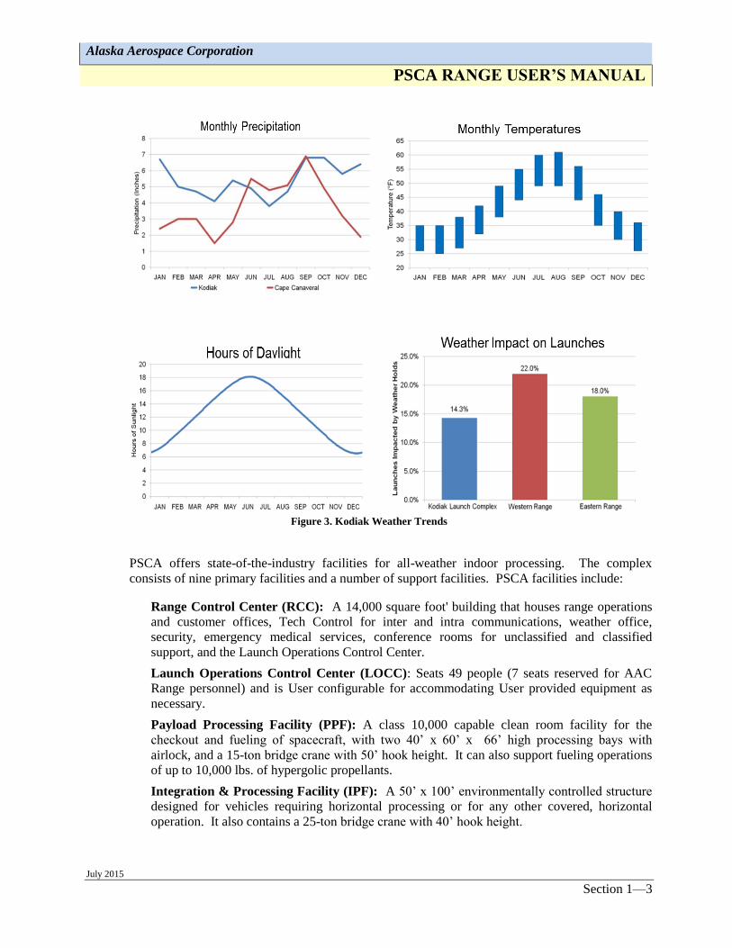
Additionally, Kodiak Island weather more closely resembles that of the Pacific Northwest instead
of Alaska. In fact, as seen below, PSCA has fewer weather delays than either Cape Canaveral
AFS or Vandenberg AFB. Also, lightning is rare on Kodiak Island and for a quarter of the year,
Kodiak has more daylight hours than other Ranges as seen in Figure 3.
Figure 2. PSCA Launch Azimuths and Inclinations
Alaska Aerospace Corporation
PSCA RANGE USER’S MANUAL
July 2015 Section 1—3
Figure 3. Kodiak Weather Trends
PSCA offers state-of-the-industry facilities for all-weather indoor processing. The complex
consists of nine primary facilities and a number of support facilities. PSCA facilities include:
Range Control Center (RCC): A 14,000 square foot' building that houses range operations
and customer offices, Tech Control for inter and intra communications, weather office,
security, emergency medical services, conference rooms for unclassified and classified
support, and the Launch Operations Control Center.
Launch Operations Control Center (LOCC): Seats 49 people (7 seats reserved for AAC
Range personnel) and is User configurable for accommodating User provided equipment as
necessary.
Payload Processing Facility (PPF): A class 10,000 capable clean room facility for the
checkout and fueling of spacecraft, with two 40’ x 60’ x 66’ high processing bays with
airlock, and a 15-ton bridge crane with 50’ hook height. It can also support fueling operations
of up to 10,000 lbs. of hypergolic propellants.
Integration & Processing Facility (IPF): A 50’ x 100’ environmentally controlled structure
designed for vehicles requiring horizontal processing or for any other covered, horizontal
operation. It also contains a 25-ton bridge crane with 40’ hook height.

Alaska Aerospace Corporation
PSCA RANGE USER’S MANUAL
July 2015 Section 1—4
Spacecraft Assemblies & Transfer Building (SCAT): A self-contained, environmentally
controlled, rail-mounted rolling structure that is used for transporting launch vehicles and
payload assemblies from the IPF to Launch Pads 1 or 2, and serves as a LP- 2 processing
enclosure.
Launch Service Structure (LSS) and Launch Pad 1 (LP-1): The 174' LSS houses LP-1,
which is mainly used for orbital launches. The LSS has a 75-ton bridge crane to hoist rocket
segments and payloads for vertical build up on the launch stool. The LSS is equipped with
moveable work platforms, adjustable in one-foot increments, and adjustable custom inserts
that accommodate a variety of launch vehicle diameters. The LSS is constructed with a 20'
diameter throat by 40' deep flame trench rated for up to 1.3 million pounds of thrust. Outside
of the LSS is the Launch Equipment Vault (LEV), a concrete structure with pass-throughs to
the pad and umbilical tower for communications, power, and conditioned air.
Launch Pad – 2 (LP-2): Used to launch sub-orbital missions, and vehicle processing can be
performed inside the SCAT by positioning it over the launch pad/stool. LP2 is supported by
the Launch Equipment Building (LEB), a small blockhouse that provides pass-throughs to
LP2. It can also accommodate customer supplied launch stools.
Instrumentation Field: A 260’ x 390’ gravel area that accommodates a wide array of Range
User instrumentation equipment and antennas as well as AAC’s Range Safety & Telemetry
System (RSTS) Mobile Operations Centers and the Mobile Telemetry System vans. This area
also houses a communications, power and fiber optics hub for interfacing to User equipment
or instrumentation.
Rocket Motor Storage Facility (RMSF): The Rocket Motor Storage Facility (RMSF) is
comprised of two Earth Covered Magazines (ECMs) for short or long term storage of rocket
motors. The RMSF is designed using the DDESB Technical Paper 15 approved 7-bar Oval
Arch Steel Magazine. Each ECM is sited for 225,000 lbs. HD 1.1 and 225,000 lbs. HD 1.3.
Maintenance and Support Facility (MSF): A 19,000 square foot building that houses PSCA
maintenance shops for all Range equipment and vehicles; as well as storage bays for RSTS
and customer equipment. MSF also houses the PSCA facilities personnel offices.
Each site within PSCA is connected by Operational Intercom System (OIS), telephone, data,
Closed Circuit Television (CCTV) and Paging and Area Warning (P/AW) systems.
Communication is by dual submarine fiber optic telecommunications systems connecting Kodiak
Island with the Kenai Peninsula and Anchorage, as well as a second connection to Seward. Both
cables onshore connection is at Narrow Cape adjacent to PSCA. Both secure and unsecure
communications can be transmitted through this system.
Public electrical power provided by the Kodiak Electric Association, along with on-site backup
generators configured with Uninterruptible Power Supplies (UPS), provide power throughout the
Complex. Potable and firefighting water, localized septic fields, paved roads, parking and work
areas complete the Complex.
PSCA accommodates a variety of Department of Defense (DoD) and commercial solid rocket
motors including Castor 120, Castor IVB, Orion 50S, and derivatives of Minuteman, Polaris,
Peacekeeper, and Trident C4 propulsion systems. Launch Vehicles supported include: Athena,
Taurus, STARS, and Minotaur series suborbital and orbiting systems. PSCA is sited for 1.1C and
1.3C solid propellants and is designed for all weather indoor processing. Additionally, a new
Environmental Assessment (EA) for solid and liquid propellant medium-lift launch vehicles,

Alaska Aerospace Corporation
PSCA RANGE USER’S MANUAL
July 2015 Section 1—5
including LOX, JP-4, JP-10 and methane is pending approval, which is expected during the
summer of 2015.
1.3 Primary Mission
PSCA’s primary mission is to serve as a west coast launch facility to commercial, government,
and military customers. PSCA’s location at Narrow Cape on Kodiak Island is ideal for space
access into polar, sun synchronous and highly elliptical orbits. PSCA offers unrestricted down
range launch azimuths ranging from 110 degrees to 220 degrees. PSCA is the nation’s highest
latitude, full service spaceport that is able to launch into high inclination orbits (including 63.4
degrees) without flight over land or high energy consuming dog-leg trajectories to reach orbit.
The PSCA has supported Government and commercial launches for agencies such as the National
Aeronautics and Space Administration (NASA), the U.S. Army Space and Missile Defense
Command (SMDC), the U.S. Air Force (USAF) Space and Missile Systems Center (SMC), and
the Missile Defense Agency (MDA), as well as Orbital Sciences, Lockheed Martin, Space Vector
Corporation, and Sandia National Labs.

Alaska Aerospace Corporation
PSCA RANGE USER’S MANUAL
July 2015 Section 2—6
SECTION 2 STRUCTURE AND METHODOLOGIES
2.1 Alaska Aerospace Corporation (AAC)
AAC is an agency of the State of Alaska, established in 1991 by the legislature to promote
development of an aerospace industry in Alaska. AAC owns and operates PSCA.
2.1.1 Organization/Charter
AAC is a public corporation created by State of Alaska Statute and governed by a Board
of Directors. AAC/PSCA management consists of a President/Chief Executive Officer,
Chief Operating Officer (COO), various engineering and administrative staff located in
Anchorage, Alaska; with PSCA facilities, operations and support staff at Kodiak, Alaska.
2.2 Authority
PSCA is a spaceport licensed by the Federal Aviation Administration Commercial Space
Transportation (FAA/AST) under provisions of the Commercial Space Launch Act (CSLA) Title
51 U.S. Code Chapter 509) to provide an orbital launch capability. The principle law governing
operations at PSCA is Title 14 CFR 420 – License to Operate a Launch Site. This CFR, PSCA’s
site operator’s license (reference LSO-03-008), and AAC’s enabling legislation (Alaska Statute
14.40.846, Article 7), all designate AAC as the final authority for ensuring flight, ground, and
operational safety at PSCA. Therefore, it is AAC’s responsibility to ensure that customers comply
with the policies and procedures developed as a condition of the operators’ license.
2.3 Services Provided
2.3.1 Range Operations Support
AAC provides tailored levels of support for licensed Launch Operators with its own
workforce, supplemented by various contractors. Some of the support services offered by
AAC include launch operations, telemetry and flight termination systems (FTS) ground
and in-flight support, communications, ground safety, and facilities maintenance. All
support by AAC is on a “task order” basis; if a customer requires support that is not
currently on contract, that support can be acquired as an additional service.
2.3.2 Facility and Logistics Support
AAC support is tailored to customer needs and includes, but is not limited to:
- Logistics, including motors/stages, equipment, supplies and personnel
- Assistance with licenses, permits and exemptions, as appropriate, including state and
federal environmental permits and transportation matters
- Payload and launch vehicle processing and operations support
- Facilities modifications and installations to configure for specific missions
- Clean Room monitoring
- Instrumentation including telemetry and range safety
- Communication at PSCA and downrange assets or Ranges

Alaska Aerospace Corporation
PSCA RANGE USER’S MANUAL
July 2015 Section 2—7
- Meteorological support
- Program-oriented security, including physical and classified
- Clerical and administrative support
- Facilities engineering and construction support
2.4 Range Organization
Launch vehicle support and operations at PSCA are conducted per the requirements of the
user’s FAA Launch Operator’s License, or other Federal agency requirements (such as
NASA or DoD). As the FAA-licensed Launch Site Operator, AAC is responsible to
ensure that all mission operations conducted from PSCA are compliant with all FAA
licenses, or with appropriate DoD launch processes that are executable within the limits of
the Launch Site Operator’s License. AAC works with the customer to tailor the specific
launch operations team and levels of support needed for the mission and license
compliance.
For any Launch Operator, AAC is able to provide all functions and positions required for
launching both commercial and DoD vehicles. These include:
Range operations management: Under the Director of Range Operations (DRO)
provides oversight of all mission operations, mission planning and Range User
interfaces at PSCA. Responsible for providing ground safety officer, facilities
readiness, range operations support, and AAC staff support.
Range Control Officer: Oversees day-to-day Range activities during mission
operations at PSCA and has the authority to approve the test, maintenance and
uses of the Range.
Range Safety Officer (RSO)/Mission Flight Control Officer (MFCO): Generally
provided through a Federal range, provides flight safety for operations at PSCA.
Facility Security Officer: Responsible for directing the overall PSCA security
program to ensure all Federal security requirements are met for Range Users along
with obtaining and maintaining approvals for classified networks, materials, and
Information Systems when required by the Range User.
Launch Weather Officer: Supports the Range Users specific mission
meteorological requirements.
These personnel actively work with the customer to support or provide all aspects of
support from pre-launch processing, the launch processing, and post-launch operations.
These positions, along with the rest of the PSCA team, provide flight safety (focused on
telemetry and flight termination systems), ground safety, scheduling, weather prediction
and tracking, facility instrumentation, on-site communications, facility and support
equipment, and logistics.
2.5 Range User Interface Procedures
The function of PSCA as an FAA-Licensed Launch Site Operator is to ensure the Launch
Operator/Range User’s safe and efficient campaigns from initiation to completion. Support

Alaska Aerospace Corporation
PSCA RANGE USER’S MANUAL
July 2015 Section 2—8
agreements are defined by a contract and supporting Statement of Work (SOW), or by a
Memorandum of Agreement (MOA). In addition, AAC has adopted a streamlined form of the
Range Commanders Council's Universal Documentation System (UDS) in order to capture Range
User requirements, as well as support approach by AAC at PSCA. The UDS is the standardized
documentation system for stating requirements and preparing range support responses that is
accepted and used at ranges operated by the Department of Defense (DoD) and National
Aeronautics and Space Administration (NASA).
2.5.1 Introduction
To determine the feasibility of conducting the proposed project at PSCA, the Range User
is encouraged to confer with AAC personnel before submitting a formal request. The
initial contact will normally lead to a meeting between the Range User and AAC Range
personnel to exchange preliminary information and to reach a tentative position on the
feasibility of conducting the project at PSCA.
2.5.2 Range User Documentation
2.5.2.1 Program Introduction (PI) Document
The PI is the Range User’s initial planning document containing the top-level
scope of requirements, milestone schedule and duration of program activities.
2.5.2.2 Program Requirements Document (PRD)
The PRD is a program planning document containing the Range User’s more
detailed project description, technical requirements, and program schedule.
This information will be assessed by AAC for supportability and cost
estimates. The PRD is required for more complex or long lead-time
programs.
2.5.2.3 Operations Requirements (OR) Document
The OR is a detailed description of the program’s requirements for each
specific test, or series of tests, and the specific support required.
2.5.3 Range Response to User Documentation
2.5.3.1 Statement of Capability (SC)
The SC is AAC’s response to the Range User’s PI. The SC is evidence that
AAC has accepted a program for support. It also serves as a baseline
reference for support conditions, qualifications, and resources understood by
AAC.
2.5.3.2 Program Support Plan (PSP)
The PSP is the response to the requirements identified in the Range User’s
PRD. It also provides detailed information for requirements that AAC is
either unable to meet or can meet in ways different than specifically requested
Alaska Aerospace Corporation
PSCA RANGE USER’S MANUAL
July 2015 Section 2—9
in the PRD. A cost estimate for Range support and/or Range modifications is
included.
2.5.3.3 Operations Directive (OD)
The OD is AAC’s response to the User’s Operations Requirements (OR)
document and is the detailed plan for implementation of specific program or
mission testing, the associated schedules, and the specific resources needed in
support of these tests.
2.5.4 Additional Documentation Requirements
2.5.4.1 Range Safety requirements, including ground safety and flight safety
documentation, are described in the AAC Range Safety Manual, which details
Range Safety Data Package (RSDP) submittals and schedule based on a
planned launch date.
2.5.4.2 Interface Control Documentation (ICD), which describes communication,
mechanical, electrical and facilities interfaces between the User and PSCA,
are required to ensure that the PSCA can be properly configured for the
mission.
2.5.5 Operations Scheduling
AAC maintains a master schedule of PSCA activities. Each Range User is to provide
AAC with a detailed schedule to be incorporated into the master schedule. Any activity
requiring AAC support must be included in the Range User’s schedule. The PSCA OD is
responsible for maintaining the daily/weekly schedule. All Range User requests for Range
support and hazardous operations must be coordinated through the OD and the PSCA
schedule.
2.5.6 Documentation Schedule
AAC attempts to avoid excessive documentation wherever possible. Although Range
Users are required to provide appropriate levels of the UDS to aid AAC in defining
support requirements, only applicable levels/sections need to be provided. Documentation
required from the Range User, with general publication dates for first-time projects, is as
follows:
Program Introduction (PI) ................................................................. L – 24 Months
Program Requirements Document (PRD) ......................................... L – 12/18 Months
PSCA Range Safety Data Requirements Check List ........................ L – 12 Months
Preliminary Range Safety Data Package (PRSDP) ........................... L – 12 Months
Trajectory Simulation Data ............................................................... L – 120 days
Final Range Safety Data Package (FRSDP) ...................................... L – 120 days
Hazardous Operations Plan (HOP) .................................................... L – 90 days
Operations Requirements (OR) ......................................................... L – 90 days

Alaska Aerospace Corporation
PSCA RANGE USER’S MANUAL
July 2015 Section 2—10
AAC responses (SC, PSP, & OD) will be submitted within 30 days of receipt from the
Range User request (PI, PRD, & OR). Schedules can be adjusted to support individual
campaign requirements. Exact data requirements shall be determined during the planning
process based on unique schedule and project details. AAC encourages Range Users to
provide documentation as early as possible to assure adequate time for review and
approval. The tailored Range Safety Data Checklist is contained in the AAC Range Safety
Manual (RSM) Appendix A - Data Requirements Checklist, and Appendix B – Range
Safety Data Requirements Tracking List and Delivery Schedule.
2.6 Security
PSCA security consists of a UL Certified state-of-the-industry Intrusion Detection System (IDS)
approved and certified by the Defense Security Services (DSS) for the control of classified
materials (physical handing and electrical transmission) as well as physical security during
operations, provided by an AAC security contractor.
Site security is provided by 8' fencing around all individual facilities. Barricades are established at
PSCA check points of entry when hazardous operations require them.
Building access is controlled by a combination of DSS approved cipher and combination spin
locks and magnetic card readers. A facility-wide key system also allows control of access to
certain work areas and individual rooms.
AAC has established operational security controls and procedures, which require Range User
compliance. These controls include controlled issuance of photo identification badges color coded
by various levels of authorized activity/area entry; security guards and check points that restrict
access to certain areas by authorized personnel only; and procedures for visitors. Range Users will
receive a detailed briefing on operational security, controls, and procedures from AAC soon after
the first contact with the AAC Security Manager.
2.7 Hazardous Waste Disposal
2.7.1 Non-Hazardous
AAC provides for the removal of non-hazardous refuse and waste limited to routine
materials generated from normal operations. The Range User is responsible for disposing
of major packing materials, shipping containers, and construction refuse.
2.7.2 Hazardous Materials
AAC will dispose of facility-related hazardous waste not directly the result of the Range
User’s launch activities. AAC staff and contract security personnel are HAZWOPER
trained at the First Responder Operations Level. In the event of a spill or release to the
environment involving a PSCA-related hazardous chemical, AAC staff and security
personnel shall follow AAC’s Emergency Response Plan procedures. In the event of a
spill or release to the environment involving a Range User-related hazardous chemical,
AAC staff and security personnel shall notify the Range User’s designated Emergency
Responder and act to protect the health and safety of nearby persons, following relevant
emergency procedures.
Alaska Aerospace Corporation
PSCA RANGE USER’S MANUAL
July 2015 Section 2—11
Range Users shall manage hazardous waste generated by their operations at PSCA,
including collection of and disposal of any by-products, in compliance with applicable
environmental regulations. For additional information, please refer to the PSCA RSM.
2.8 Fire Protection and Medical Support
AAC fire support consists of fire detection and protection equipment at PSCA. Fire protection
systems at the individual buildings are supported by a 169,000-gallon water storage tank and pump
station located at the PPF. This pump distributes water through a distribution system to each
facility. Fire hydrants are located along the distribution main. Systems for individual buildings
are described separately. An onsite pumper fire truck provides wildfire suppression.
Fire, ambulance, and medical evacuation coverage is provided by Kodiak Island emergency
services organizations, within normal non-service district response times. Additional fire,
ambulance, and medical support can be negotiated in the launch services agreement.

Alaska Aerospace Corporation
PSCA RANGE USER’S MANUAL
July 2015 Section 3—12
SECTION 3 RANGE FACILITIES OVERVIEW
3.1 Range Control Center (RCC)
The RCC is the administrative, engineering and operations support facility for PSCA. It is the
primary communications and data center for Range functions and is connected throughout the
facilities by the communications backbone. Located approximately two miles away from the LP-
1 & 2, the RCC is outside the safety hazard zone, thus ensuring the safety of mission personnel.
The RCC houses the Launch Operations Control Center (LOCC), the Tech
Control/Communications Room, administrative and engineering support personnel offices,
conferences rooms, restrooms/showers, and break room. A facility of approximately 14,000
square feet, the RCC provides both private office and open space areas primarily for Range
Users. Figure 4 shows the exterior of the RCC.
Figure 4. Exterior of Range Control Center
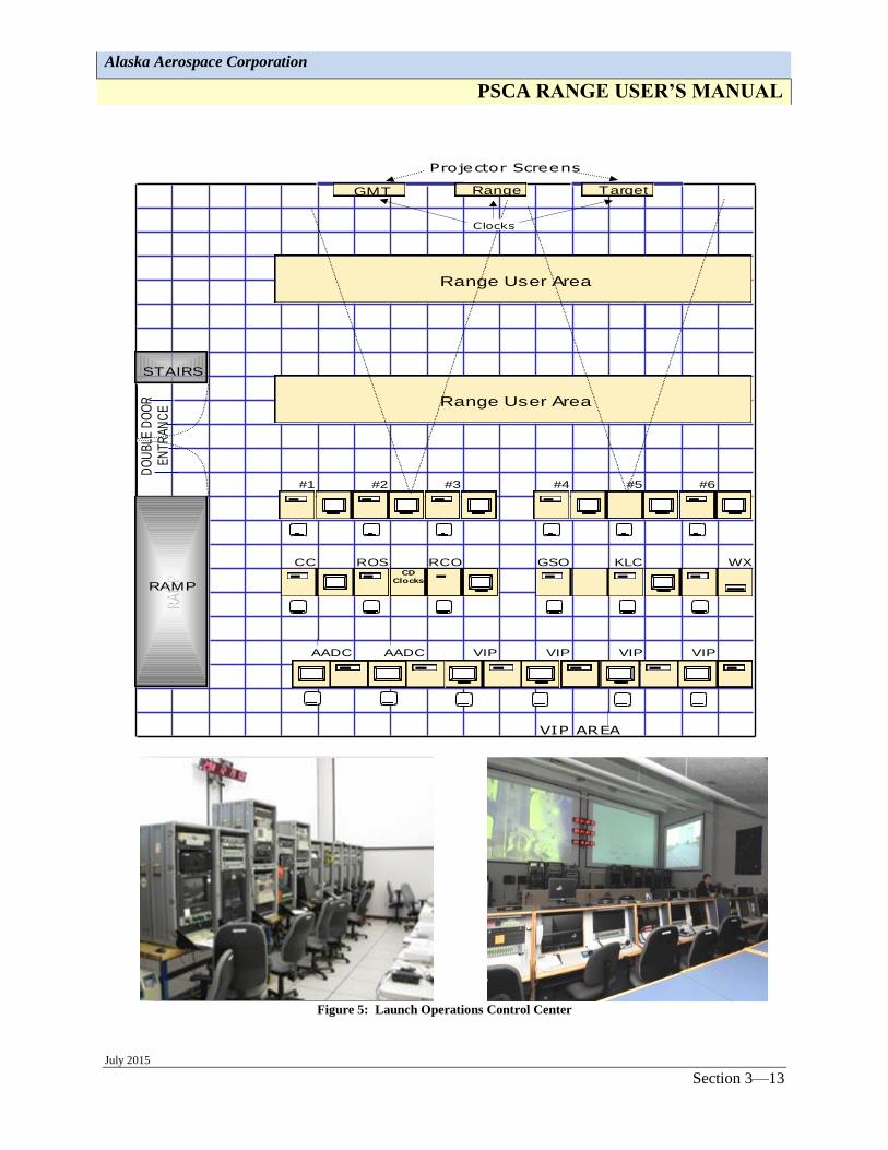
3.1.1 Launch Operations Control Center (LOCC)
The LOCC is approximately 1,610 square feet and has raised flooring that allows for
console reconfiguration. The LOCC is connected with an under-floor cable-way to the
Tech Control to accommodate connectivity changes. The LOCC has both fiber optic and
satellite communications connectively for worldwide communications and data
distribution, both secure and non-secure.
The LOCC seats up to 49 people with operations consoles for AAC and Range User
personnel. Workstations consist of computer monitors, keyboards, and CPUs. The
mission voice network or Operational Intercom System (OIS) is also distributed to each
workstation. The configuration below in Figure 5 is an example of how the LOCC can be
configured.
Alaska Aerospace Corporation
PSCA RANGE USER’S MANUAL
July 2015 Section 3—13
Figure 5: Launch Operations Control Center
#1 #2 #3 #4 #5 #6
CC ROS RCO GSO KLC WX
AADC AADC VIP VIP VIP VIP
VIP AREA
RAM
P
DO
UB
LE D
OO
R
EN
TR
AN
CE
Projector Screens
CD Clocks
Target
RAMP
STAIRS
Range User Area
Range User Area
GMT Range
Clocks

Alaska Aerospace Corporation
PSCA RANGE USER’S MANUAL
July 2015 Section 3—14
3.1.2 Engineering Office Area
The engineering office area (4,059 square feet) seen below in Figure 6, offers partitioned
offices and cubicles. This area is generally configured to support 64 cubicles and offices.
Electrical power, telephone and data connections are provided to each workstation. A
dedicated customer Local Area Network (LAN) is provided for printing and internet
access.
Figure 6. Enginering Office Area
3.1.3 Tech Control
The Tech Control/Communications includes the communications and network equipment
shown in Figure 7. This area houses the core of the communications system, timing and
countdown, PA, CCTV, telephone, and the interface for the HVDS. Tech Control is also
the interface point for external copper and fiber distribution cabling from other PSCA
facilities and Range User equipment.
Figure 7. Typical Tech Control Equipment
Alaska Aerospace Corporation
PSCA RANGE USER’S MANUAL
July 2015 Section 3—15
3.1.4 Backup Power
The RCC has its own backup generator and UPS. A stand-by 350kW generator supplies
power to the entire building during outages. The generator fuel tank is sized to run the
generator for a minimum of 72 hours at full load. Each generator at the PSCA is
contained in heated enclosures. A total of 32 kVA UPS are located in the Tech Control.
The UPS supplies uninterruptible power to critical communications systems and Range
User equipment.
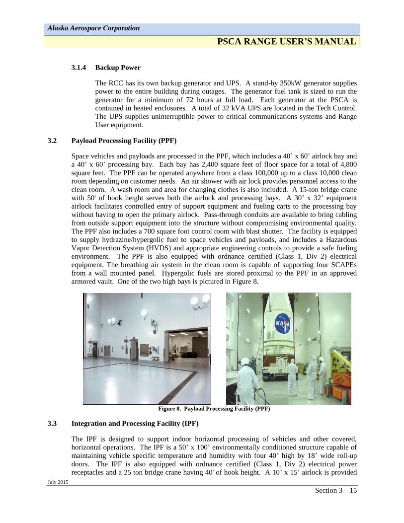
3.2 Payload Processing Facility (PPF)
Space vehicles and payloads are processed in the PPF, which includes a 40’ x 60’ airlock bay and
a 40’ x 60’ processing bay. Each bay has 2,400 square feet of floor space for a total of 4,800
square feet. The PPF can be operated anywhere from a class 100,000 up to a class 10,000 clean
room depending on customer needs. An air shower with air lock provides personnel access to the
clean room. A wash room and area for changing clothes is also included. A 15-ton bridge crane
with 50' of hook height serves both the airlock and processing bays. A 30’ x 32’ equipment
airlock facilitates controlled entry of support equipment and fueling carts to the processing bay
without having to open the primary airlock. Pass-through conduits are available to bring cabling
from outside support equipment into the structure without compromising environmental quality.
The PPF also includes a 700 square foot control room with blast shutter. The facility is equipped
to supply hydrazine/hypergolic fuel to space vehicles and payloads, and includes a Hazardous
Vapor Detection System (HVDS) and appropriate engineering controls to provide a safe fueling
environment. The PPF is also equipped with ordnance certified (Class 1, Div 2) electrical
equipment. The breathing air system in the clean room is capable of supporting four SCAPEs
from a wall mounted panel. Hypergolic fuels are stored proximal to the PPF in an approved
armored vault. One of the two high bays is pictured in Figure 8.
Figure 8. Payload Processing Facility (PPF)
3.3 Integration and Processing Facility (IPF)
The IPF is designed to support indoor horizontal processing of vehicles and other covered,
horizontal operations. The IPF is a 50’ x 100’ environmentally conditioned structure capable of
maintaining vehicle specific temperature and humidity with four 40’ high by 18’ wide roll-up
doors. The IPF is also equipped with ordnance certified (Class 1, Div 2) electrical power
receptacles and a 25 ton bridge crane having 40' of hook height. A 10’ x 15’ airlock is provided

Alaska Aerospace Corporation
PSCA RANGE USER’S MANUAL
July 2015 Section 3—16
to accommodate transfer of support items without compromising environmental control. A Test
Assemblies Inspection Records Room, washroom/lavatory, and mechanical room complete the
structure. Stepdown transformers and switch panels supply 208-480V, 3 phase and 120V single
phase throughout the IPF. The IPF is located two miles away from the RCC. The IPF is
pictured in Figure 9.
Figure 9. Integration and Processing Facility (IPF)
3.4 Spacecraft Assemblies & Transfer Building (SCAT)/Launch Pad-2 (LP-2)
The SCAT building is a self-contained, environmentally controlled mobile structure that houses
LP-2 and is used for transporting launch vehicle and payload assemblies from the IPF to the
launch pads. The SCAT is 45’ wide and 70’ long, with a 60’ high ceiling, with four roll-up
doors. Three doors are 40’ high by 18’ wide, and one door is 43’ high to allow SCAT removal
from the stool-mounted launch vehicles while on the LP-2 launcher. This structure is roller
mounted on tracks between the IPF and the LSS. Also, the SCAT is available as a launch vehicle
processing building when positioned over LP-2. Ordnance certified (Class 1, Div 2) electrical
power receptacles and 25 ton bridge crane with 45’ hook height service the SCAT. Both primary
(750 KW) and backup generator (600 KW) power, with auto switchover, are available to the IPF-
SCAT and launcher area. Electrical heaters and humidifiers provide environmental control. The
SCAT/LP-2 is pictured in Figure 10.
The reinforced concrete LEB, located adjacent to the LP-2, is environmentally controlled, and
offers 108 square feet of floor space to house User electrical ground support equipment (GSE).
Conduit pass-throughs are available between the LEB and the LP-2 to accommodate User
umbilical connectivity.
Figure 10. SCAT/Launch Pad-2

Alaska Aerospace Corporation
PSCA RANGE USER’S MANUAL
July 2015 Section 3—17
3.5 Launch Service Structure (LSS)/Launch Pad-1 (LP-1)
The LP-1 consists of a 174' tall LSS, which will accommodate Minotaur, Taurus, Athena, Vega,
Shavit, and Epsilon class vehicles. The LSS is an environmentally controlled, all weather facility,
with adjustable height and adjustable diameter work platforms, flame trench, transporter erector
accommodation, side entry with booster break-over accommodations, and fiber and copper
connectivity to the RCC/LOCC. The LSS is also equipped with ordnance certified (Class 1, Div
2) electrical power receptacles and has a 75-ton bridge crane to hoist rocket segments and
payloads for vertical build up on the launch stool. Prior to launch, two rotating building sections
are rotated clear of the launch vehicle. The LSS is also equipped with OIS, telephone, data,
CCTV, and Paging/Area Warning systems. Stepdown transformers and switch panels supply
208-480V, 3 phase and 120V single phase.
The reinforced concrete Launch Equipment Vault (LEV), located adjacent to the LSS, is
environmentally controlled, and offers 331 square feet of floor space to house User launch
vehicle electrical ground support equipment (GSE). Conduit pass-throughs are available between
the LEV and LP-1 to accommodate umbilical connectivity. The LSS/LP-1 is pictured in Figure
11.
Figure 11. Launch Service Structure (LSS)/Launch Pad-1 (LP-1)
3.6 Instrumentation Field
The instrumentation field, a 260’ x 390’ packed gravel parking area, is situated to the west of the
RCC and occupies higher ground. It provides line of sight to LP-1 and LP-2 and accommodates a
wide variety of Range User’s instrumentation and antennas. It also houses the PSCA’s Range
Safety & Telemetry System (RSTS) seen in Figure 12. The instrumentation field is secured by an
8’ barbwire topped fence and includes the Antenna Field Utility Building (AFUB), Range Radio
Equipment Building (RREB) and antenna pads. The AFUB supplies power and communication,
via copper, fiber, and coax, to meet customer requirements. A single, 500 KVA transformer
converts 480V to provide lugged 1-phase or 3-phase 120/208 VAC volts. The RREB facilitates
radio communication throughout the entire complex.

Alaska Aerospace Corporation
PSCA RANGE USER’S MANUAL
July 2015 Section 3—18
Figure 12. Instrumentation & Antenna Field
3.7 Rocket Motor Storage Facility (RMSF)
The Rocket Motor Storage Facility (RMSF) shown in Figure 13, is comprised of two Earth
Covered Magazines (ECM’s) for short or long term storage of rocket motors. The RMSF is
designed using the DDESB Technical Paper 15 approved 7-bar Oval Arch Steel Magazine design
number 421-80-03. Each ECM is sited for 225,000 lbs. HD 1.1 and 225,000 lbs. HD 1.3. The
RMSF allows multiple customers to have motors at PSCA at the same time. The 7-bar DDESB
approved design of each ECM will protect the contents of the magazine even if there is
detonation in an adjacent magazine. The RMSF is separated from the lower range by Intra-Line
Distance (ILD) in order to provide direct support to the launch pad area, regardless of the
mission.
Figure 13. RMSF Storage Bunkers

Alaska Aerospace Corporation
PSCA RANGE USER’S MANUAL
July 2015 Section 3—19
3.8 Maintenance and Support Facility (MSF)
The MSF is a 19,000 square foot building housing three large maintenance and support bays that
provide all-weather in-door equipment maintenance and support areas for PSCA. One of the 3
bays can be dedicated for Range User support. The MSF is pictured in Figure 14.
Figure 14. Maintenance and Support Facility (MSF)
3.9 Narrow Cape Lodge
The Narrow Cape Lodge, seen in Figure 15, is a privately-owned facility is located approximately
3 miles from the RCC, providing lodging and food services to AAC clients when at PSCA. The
Lodge has 56 rooms, a large dining hall, and a recreation room. Each room has a private bath,
telephone/Internet, and television. Laundry facilities are available on-site.
Figure 15. Narrow Cape Lodge
Alaska Aerospace Corporation
PSCA RANGE USER’S MANUAL
July 2015 Section 4—20
SECTION 4 PSCA INSTRUMENTATION
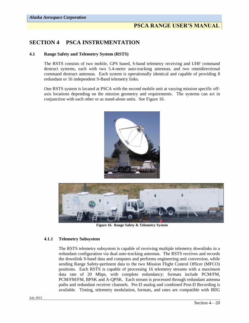
4.1 Range Safety and Telemetry System (RSTS)
The RSTS consists of two mobile, GPS based, S-band telemetry receiving and UHF command
destruct systems, each with two 5.4-meter auto-tracking antennas, and two omnidirectional
command destruct antennas. Each system is operationally identical and capable of providing 8
redundant or 16 independent S-Band telemetry links.
One RSTS system is located at PSCA with the second mobile unit at varying mission specific off-
axis locations depending on the mission geometry and requirements. The systems can act in
conjunction with each other or as stand-alone units. See Figure 16.
Figure 16. Range Safety & Telemetry System
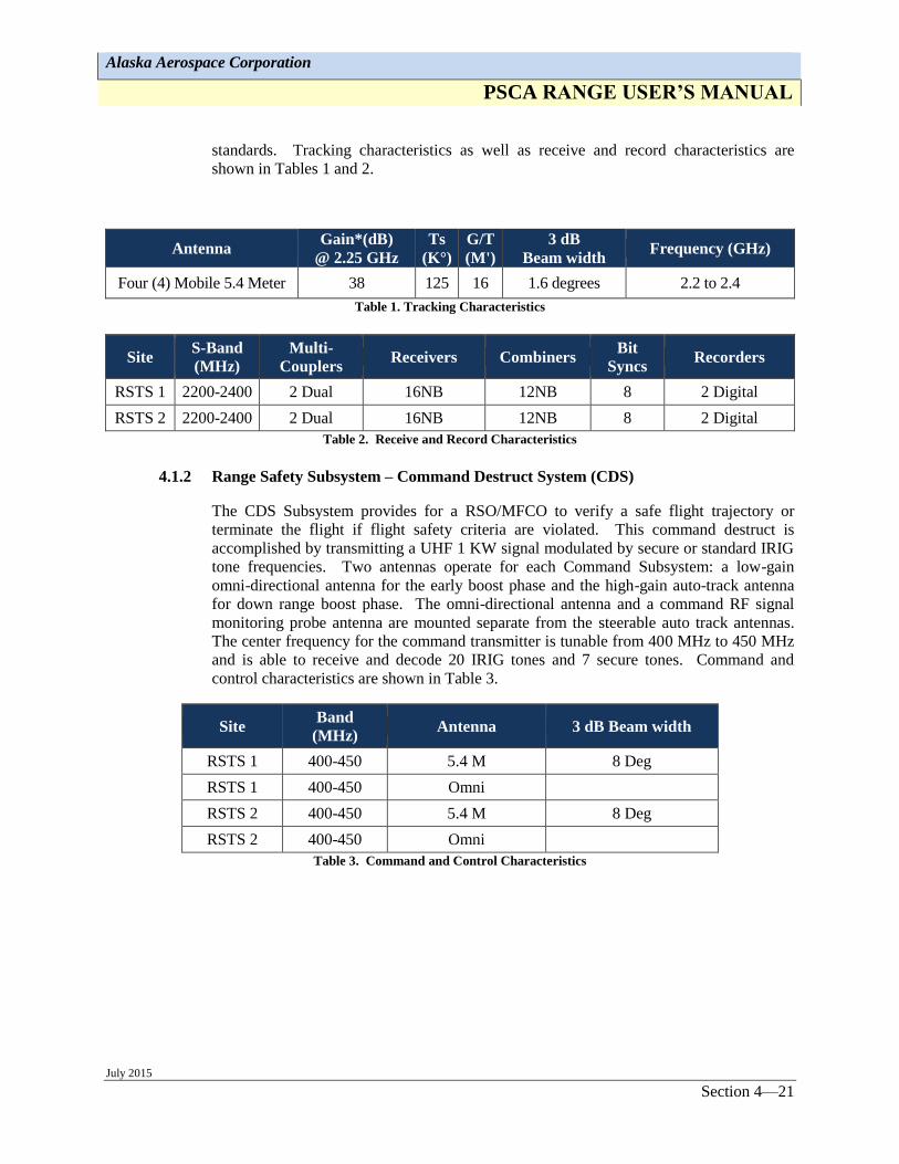
4.1.1 Telemetry Subsystem
The RSTS telemetry subsystem is capable of receiving multiple telemetry downlinks in a
redundant configuration via dual auto-tracking antennas. The RSTS receives and records
the downlink S-band data and computes and performs engineering unit conversion, while
sending Range Safety-pertinent data to the two Mission Flight Control Officer (MFCO)
positions. Each RSTS is capable of processing 16 telemetry streams with a maximum
data rate of 20 Mbps, with complete redundancy: formats include PCM/FM,
PCM/FM/FM, BPSK and A-QPSK. Each stream is processed through redundant antenna
paths and redundant receiver channels. Pre-D analog and combined Post-D Recording is
available. Timing, telemetry modulation, formats, and rates are compatible with IRIG
Alaska Aerospace Corporation
PSCA RANGE USER’S MANUAL
July 2015 Section 4—21
standards. Tracking characteristics as well as receive and record characteristics are
shown in Tables 1 and 2.
Antenna Gain*(dB)
@ 2.25 GHz
Ts
(K°)
G/T
(M')
3 dB
Beam width Frequency (GHz)
Four (4) Mobile 5.4 Meter 38 125 16 1.6 degrees 2.2 to 2.4
Table 1. Tracking Characteristics
Site S-Band
(MHz)
Multi-
Couplers Receivers Combiners
Bit
Syncs Recorders
RSTS 1 2200-2400 2 Dual 16NB 12NB 8 2 Digital
RSTS 2 2200-2400 2 Dual 16NB 12NB 8 2 Digital
Table 2. Receive and Record Characteristics
4.1.2 Range Safety Subsystem – Command Destruct System (CDS)
The CDS Subsystem provides for a RSO/MFCO to verify a safe flight trajectory or
terminate the flight if flight safety criteria are violated. This command destruct is
accomplished by transmitting a UHF 1 KW signal modulated by secure or standard IRIG
tone frequencies. Two antennas operate for each Command Subsystem: a low-gain
omni-directional antenna for the early boost phase and the high-gain auto-track antenna
for down range boost phase. The omni-directional antenna and a command RF signal
monitoring probe antenna are mounted separate from the steerable auto track antennas.
The center frequency for the command transmitter is tunable from 400 MHz to 450 MHz
and is able to receive and decode 20 IRIG tones and 7 secure tones. Command and
control characteristics are shown in Table 3.
Site Band
(MHz) Antenna 3 dB Beam width
RSTS 1 400-450 5.4 M 8 Deg
RSTS 1 400-450 Omni
RSTS 2 400-450 5.4 M 8 Deg
RSTS 2 400-450 Omni
Table 3. Command and Control Characteristics

Alaska Aerospace Corporation
PSCA RANGE USER’S MANUAL
July 2015 Section 5—22
SECTION 5 TECHNICAL SYSTEMS
5.1 Fiber Optic and Copper Backbone Systems
Fiber optics and copper communications lines are run underground throughout the PSCA. The
Tech Control is the central hub between the Instrumentation Field, PPF, IPF, LEB, and LEV. At
each facility, connectivity is available for customer use.
5.2 Communications Systems
PSCA’s modern communication infrastructure includes fiber optic marine cable to mainland
Alaska and the lower 48 states. Offsite communication is provided through fiber optic marine
cable via Tech Control downlinking to locations required by the Range User. The locations
include, but are not limited to, Anchorage, Cordova, and Seattle. This system provides T-1 and IP
based services for voice, data, and Internet connections. If fiber optics us unavailable at an off-
axis site, communications would be routed through satellite communication (SATCOM) ground
station with its antenna located at PSCA. Communication from the Launch Pads to the other
facilities at PSCA is via telephone, operational intercom, paging, and the data network. All
communications, security, fire alarm, and area warning are controlled at the resident facilities and
report back to Tech Control.
5.2.1 Telephone
A PBX telephone system provides phone communications throughout PSCA. This
system is configurable to allow controlled access to long distance service.
The phone system interfaces with the OIS allowing remote users to monitor various
intercom networks. Phone location and quantity may be specified for each campaign.
5.2.2 Operational Intercommunication System (OIS)
The OIS is installed throughout the PSCA. The OIS is a Quintron DICES IV intercom
system and can be connected depending on Range User requirements. Presently, the
system is configured for a combination of 16 T-1 lines.
The OIS interfaces with the telephone and P/AW systems to allow monitoring of the OIS
by remote users via telephone and paging initiation on the P/AW system. The OIS
provides direct communication from station to station. Stations are either 24 or 6 channel
with handsets and headsets, depending on location and need.
5.2.3 Paging and Area Warning (P/AW)
The P/AW system provides paging and initiation of area warnings such as hazardous
operations, lightning alerts, or security concerns throughout the PSCA.
Each facility is equipped with direct access to the paging system through a dedicated
station with speakers located to allow dissemination of pages or area warnings throughout
interior and exterior areas. At the direction of the Launch Director or PSCA Range
personnel, a pre-programmed alert signal can be sounded throughout the Complex.
Alaska Aerospace Corporation
PSCA RANGE USER’S MANUAL
July 2015 Section 5—23
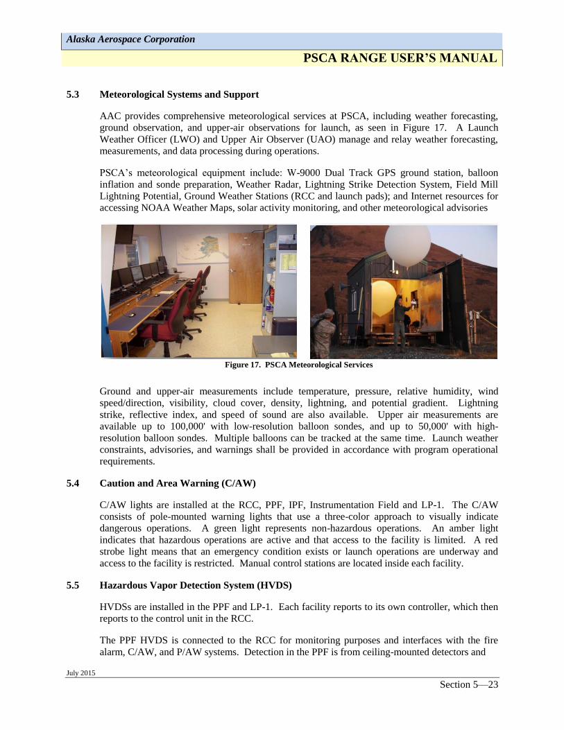
5.3 Meteorological Systems and Support
AAC provides comprehensive meteorological services at PSCA, including weather forecasting,
ground observation, and upper-air observations for launch, as seen in Figure 17. A Launch
Weather Officer (LWO) and Upper Air Observer (UAO) manage and relay weather forecasting,
measurements, and data processing during operations.
PSCA’s meteorological equipment include: W-9000 Dual Track GPS ground station, balloon
inflation and sonde preparation, Weather Radar, Lightning Strike Detection System, Field Mill
Lightning Potential, Ground Weather Stations (RCC and launch pads); and Internet resources for
accessing NOAA Weather Maps, solar activity monitoring, and other meteorological advisories
Figure 17. PSCA Meteorological Services
Ground and upper-air measurements include temperature, pressure, relative humidity, wind
speed/direction, visibility, cloud cover, density, lightning, and potential gradient. Lightning
strike, reflective index, and speed of sound are also available. Upper air measurements are
available up to 100,000' with low-resolution balloon sondes, and up to 50,000' with high-
resolution balloon sondes. Multiple balloons can be tracked at the same time. Launch weather
constraints, advisories, and warnings shall be provided in accordance with program operational
requirements.
5.4 Caution and Area Warning (C/AW)
C/AW lights are installed at the RCC, PPF, IPF, Instrumentation Field and LP-1. The C/AW
consists of pole-mounted warning lights that use a three-color approach to visually indicate
dangerous operations. A green light represents non-hazardous operations. An amber light
indicates that hazardous operations are active and that access to the facility is limited. A red
strobe light means that an emergency condition exists or launch operations are underway and
access to the facility is restricted. Manual control stations are located inside each facility.
5.5 Hazardous Vapor Detection System (HVDS)
HVDSs are installed in the PPF and LP-1. Each facility reports to its own controller, which then
reports to the control unit in the RCC.
The PPF HVDS is connected to the RCC for monitoring purposes and interfaces with the fire
alarm, C/AW, and P/AW systems. Detection in the PPF is from ceiling-mounted detectors and
Alaska Aerospace Corporation
PSCA RANGE USER’S MANUAL
July 2015 Section 5—24
from portable detectors positioned by the Range User for optimum detection. Each HVDS will
be fitted with chemical sensors specific to the chemicals to be detected (i.e., hydrazine,
ammonia).
Hazardous vapor detection in the LSS is provided through portable detectors positioned by the
Range User. Connection points are available on work levels where detectors are expected to be
placed. The detection of a hazardous vapor condition will initiate audio and visual alarms at the
affected facility and at the fire alarm control panel in the RCC.
5.6 Security
Each facility has a security system consisting of intrusion detection devices that are connected to
a control panel. The PSCA site security systems are UL-certified. Entry and passive sensors are
used to monitor access and detect intrusion. Secure locking systems are used to controls access.
The security systems function by transmitting status, integrity, and alarms signals to local and
remote units. Alarms are both visible and audible.
5.7 Closed Circuit Television (CCTV)
CCTV is available in each of the PSCA facilities. A video switch located in Tech Control
determines what displays have access to individual camera outputs and allows slave control for
Range User predetermined cameras so that monitoring and control of cameras can be
accomplished from the LOCC.
In the PPF, local control of cameras is available in the PPF Control Room. At LP-1, local control
for tower and pad perimeter cameras is available from the Launch Equipment Vault (LEV).
5.8 Timing Systems: Real-Time, Mission Clock, Countdown Clock
Timing information is available throughout the Complex with Time of Day (TOD), countdown,
and mission elapsed-time displays in various locations. The system consists of a master
controller in the RCC. Display units are located in the RCC, LOCC, PPF, and IPF. The display
unit consists of three items: GMT or Zulu time, Range time, and LV/missile countdown time.
These units are wall mounted in strategic places in each facility.
Timing is based on either an IRIG-B or IRIG-G signal format. TOD is based on GPS time from a
receiver at the RCC. The IRIG-B signal is available at BNC (Bayonet Neill- Concellman)
connector outlets in the PPF and IPF for connection to Range User equipment.
5.9 Power Distribution
5.9.1 Commercial Power Interface
Primary commercial electrical power is supplied at 24,000 Volts via an underground grid to step
down transformers at each of the three main launch and processing facilities. Each facility has
switch panels, with 480/277V, 3 phases, 120/208V, 3 phase and 120/240V single phase for
distribution to the equipment. Single phase 220 V power is available upon request. Additional
power capacity is available with site modifications.
Electrical receptacles in hazardous materials processing areas are Class 1/Div 2 ordnance
certified. Receptacles in administrative and non-hazardous processing areas are standard.
Alaska Aerospace Corporation
PSCA RANGE USER’S MANUAL
July 2015 Section 5—25
5.9.2 Backup Power
Each generator starts automatically upon loss of power and provides backup power for essential
equipment within the PSCA. The minimum operating time of each generator is 72 hours for
normal operations.
Uninterrupted power supply (UPS) backup is provided for critical equipment in areas where
required. Range Users may bring their own UPS system for Range User-supplied equipment.
5.10 Electrical Grounding and Lightning Protection
Non-ordnance related electrical grounding and bonding systems at PSCA are installed according
to articles 250 and 500 of the National Electrical Code (NEC).
Ordnance grounds, where ordnance is stored and tested on vehicles (PPF, IPF, LP-1 and LP-2),
are provided via dedicated ground buss bars connected directly to the ground grid. The ordnance
vaults are also tied to this ground grid. Ordnance grounds are tested biannually and at the request
of customers, and are in accordance with AFMAN 91-201 section 2.52 and 2.53, and Air Force
Instruction (AFI) 32-1065, Grounding Systems.
PSCA’s high voltage transformers are equipped with counterpoises that are connected to the
ground grid at each facility having a transformer. Each occupied building has a buried copper
ground grid surrounding its perimeter. Building steel is bonded to the grid at several locations.
The mobile SCAT is connected to the grid by hot line clamps.
Lightning protection is provided on PSCA facilities in accordance with National Fire Protection
(NFPA) Standard 780 Lightning Protection Code. A 10' air terminal on top of a 42' 5" in tower
provides lightning protection when the SCAT is located away from LP-2. Grounding grids are
tested biannually and upon customer request. Chain link fences are also grounded. High voltage
main facility power conduits are buried; grid continuity is provided by copper cable bonded to the
building grids.
5.11 Fire Protection, Alarm and Reporting
An automated pre-action system provides fire protection for the PPF and IPF facilities. Hydrant
service is available at the RCC. A 4-inch Class II standpipe is provided for the LSS with fire
hoses provided at each work level. Additional site fire protection is provided for by fire hydrants
located in parking lots and along the main road and access drives and a 750-gallon pumper fire
truck.
Each facility has its own fire alarm, detection system, and fire alarm control panel. Each fire
alarm control panel reports back to the Master Display Unit in the RCC. The Master Display
Unit has a modem connection for off-site reporting to AAC personnel. Additionally, sensors
automatically activate zoned sprinkler systems in the PPF and IPF.
5.12 Cranes
Bridge cranes are located in the PPF, IPF, LP-2/SCAT, MSF, and LP-1/LSS. AAC personnel
maintain and safety-certify each crane. Crane operation during payload processing is performed
by the Range User’s personnel or AAC personnel, if desired. Operators must be certified as
operators of the specific cranes. Range Users are required to submit a list of critical and flight
Alaska Aerospace Corporation
PSCA RANGE USER’S MANUAL
July 2015 Section 5—26
hardware certified crane operators to AAC prior to operating any crane. AAC personnel shall
provide familiarization for crane operation to Range Users as required.
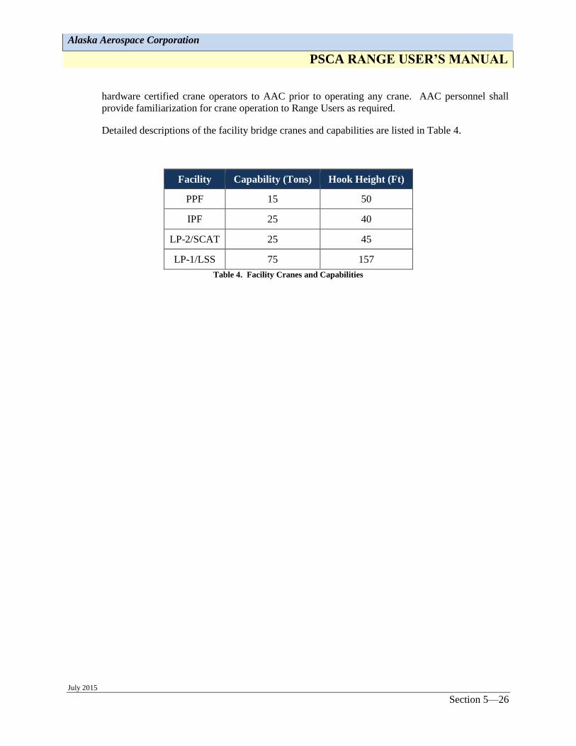
Detailed descriptions of the facility bridge cranes and capabilities are listed in Table 4.
Facility Capability (Tons) Hook Height (Ft)
PPF 15 50
IPF 25 40
LP-2/SCAT 25 45
LP-1/LSS 75 157
Table 4. Facility Cranes and Capabilities
Alaska Aerospace Corporation
PSCA RANGE USER’S MANUAL
July 2015 Section 6—27
SECTION 6 KODIAK LOGISTICS AND SUPPORT SERVICES
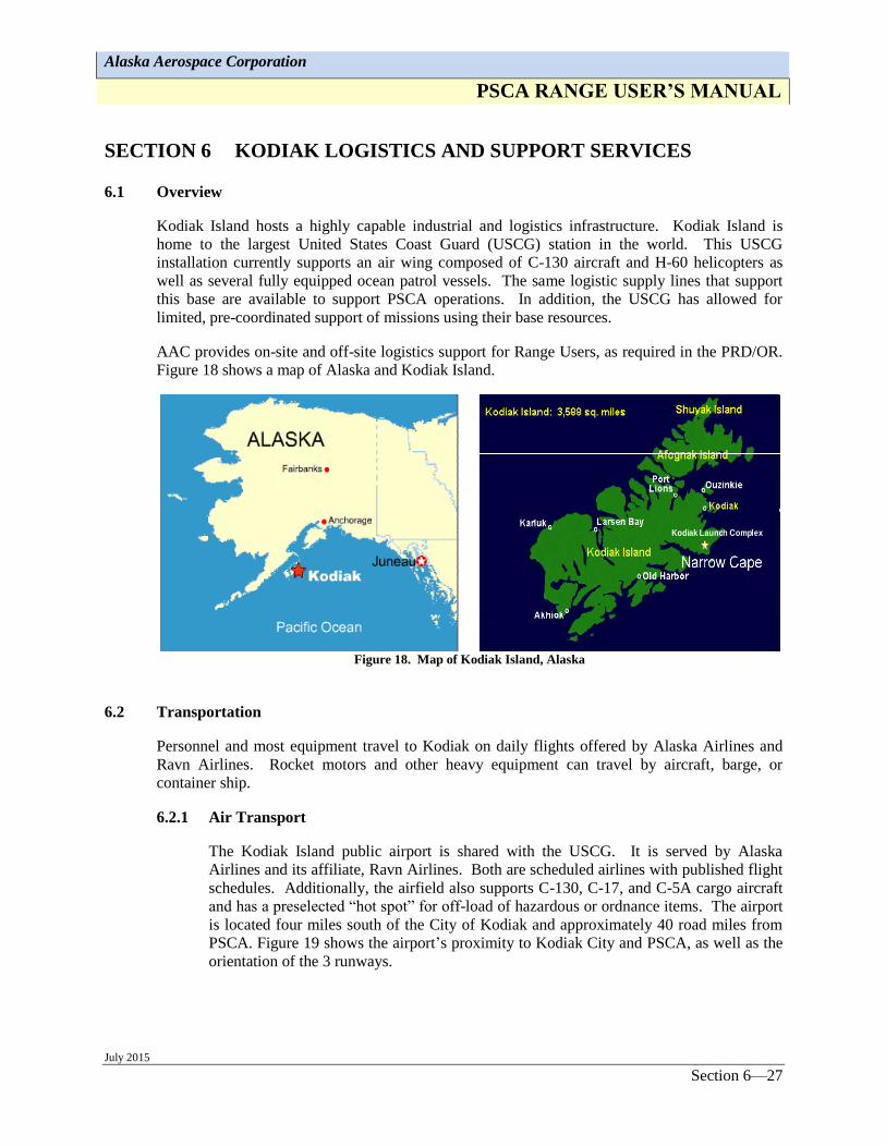
6.1 Overview
Kodiak Island hosts a highly capable industrial and logistics infrastructure. Kodiak Island is
home to the largest United States Coast Guard (USCG) station in the world. This USCG
installation currently supports an air wing composed of C-130 aircraft and H-60 helicopters as
well as several fully equipped ocean patrol vessels. The same logistic supply lines that support
this base are available to support PSCA operations. In addition, the USCG has allowed for
limited, pre-coordinated support of missions using their base resources.
AAC provides on-site and off-site logistics support for Range Users, as required in the PRD/OR.
Figure 18 shows a map of Alaska and Kodiak Island.
Kodiak Launch Complex
Figure 18. Map of Kodiak Island, Alaska
6.2 Transportation
Personnel and most equipment travel to Kodiak on daily flights offered by Alaska Airlines and
Ravn Airlines. Rocket motors and other heavy equipment can travel by aircraft, barge, or
container ship.
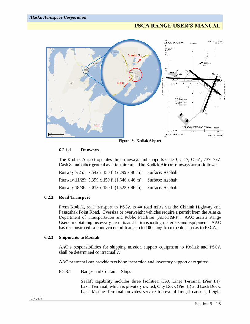
6.2.1 Air Transport
The Kodiak Island public airport is shared with the USCG. It is served by Alaska
Airlines and its affiliate, Ravn Airlines. Both are scheduled airlines with published flight
schedules. Additionally, the airfield also supports C-130, C-17, and C-5A cargo aircraft
and has a preselected “hot spot” for off-load of hazardous or ordnance items. The airport
is located four miles south of the City of Kodiak and approximately 40 road miles from
PSCA. Figure 19 shows the airport’s proximity to Kodiak City and PSCA, as well as the
orientation of the 3 runways.
Alaska Aerospace Corporation
PSCA RANGE USER’S MANUAL
July 2015 Section 6—28
Figure 19. Kodiak Airport
6.2.1.1 Runways
The Kodiak Airport operates three runways and supports C-130, C-17, C-5A, 737, 727,
Dash 8, and other general aviation aircraft. The Kodiak Airport runways are as follows:
Runway 7/25: 7,542 x 150 ft (2,299 x 46 m) Surface: Asphalt
Runway 11/29: 5,399 x 150 ft (1,646 x 46 m) Surface: Asphalt
Runway 18/36: 5,013 x 150 ft (1,528 x 46 m) Surface: Asphalt
6.2.2 Road Transport
From Kodiak, road transport to PSCA is 40 road miles via the Chiniak Highway and
Pasagshak Point Road. Oversize or overweight vehicles require a permit from the Alaska
Department of Transportation and Public Facilities (ADoT&PF). AAC assists Range
Users in obtaining necessary permits and in transporting materials and equipment. AAC
has demonstrated safe movement of loads up to 100' long from the dock areas to PSCA.
6.2.3 Shipments to Kodiak
AAC’s responsibilities for shipping mission support equipment to Kodiak and PSCA
shall be determined contractually.
AAC personnel can provide receiving inspection and inventory support as required.
6.2.3.1 Barges and Container Ships
Sealift capability includes three facilities: CSX Lines Terminal (Pier III),
Lash Terminal, which is privately owned, City Dock (Pier II) and Lash Dock.
Lash Marine Terminal provides service to several freight carriers, freight
Alaska Aerospace Corporation
PSCA RANGE USER’S MANUAL
July 2015 Section 6—29
forwarders, and consolidators. Boyer Towing, Carlisle Transportation with
Foss, and Samson Tug & Barge serve Kodiak from Seattle and Anchorage
and are familiar with aerospace transport requirements.
The Lash Terminal located south of the USCG Station and on the main road
to PSCA, is a roll-on, roll-off operation with 150-ton lift capability provided
by mobile crane. Heavier crane-lift requirements are met by transporting the
required crane on the barge. The Lash Terminal is licensed for explosive and
hazardous materials handling. Seaport Terminal Services, Inc. operates the
terminal and provides necessary support services. The terminal has 1,200
square feet of dock space as well as a warehouse. The city dock is serviced
by both containerized ocean shippers and barge carriers.
6.2.3.2 Ferry
The Kodiak Terminal, as part of the Alaska Marine Highway System
(AMHS) South Central route, provides ferry service to and from Kodiak
Island. Passenger and vehicle services, including commercial and
construction equipment vehicles, are available. Up-to-date arrival and
departure schedules, routes, and rates are easily accessed on the Internet at:
- http://www.alaska.gov/ferry, a site that provides fee, schedule, and
booking information for the AMHS.
- http://www.akferry.org, a site that provides information specific to
Kodiak Island ferries.
6.2.3.3 Air Freight
Both jet and turboprop services are available to the Kodiak airport, which is
fully IFR instrumented, operates three runways (7,500', 6,500', and 5,500' in
length), and supports C-130, C-17, C-5A, 737, Dash 8, and general aviation
aircraft.
6.2.3.4 Small Parcel Service
Express package delivery is available through the USPS, FedEx, DHL, Gold
Streak, and UPS. Second-day and Priority air shipping are available to
Kodiak. Customers can arrange to have their parcels delivered to a
prearranged location in Kodiak City or PSCA.
6.3 Accommodations for Personnel
6.3.1 Food and Lodging near PSCA
The Narrow Cape Lodge is a private enterprise that is three miles from PSCA-RCC, and
is the only commercial lodging for Range Users available close to the Range. The
Narrow Cape Lodge has 56 single rooms, each equipped with a full-size bed, Internet
access, phone service, private bathroom, and television. The first floor dining hall
comfortably seats up to 60 people for dining. Meals are served buffet style, but menu
service is available on request. Meals can be provided at PSCA during countdown dress

Alaska Aerospace Corporation
PSCA RANGE USER’S MANUAL
July 2015 Section 6—30
rehearsals and meetings that require uninterrupted operations at PSCA. On-site laundry
facilities are available 24 hours a day. The lounge area can be used for large meetings
and briefings. A recreation room is available for guests’ use.
6.3.2 Food and Lodging in Kodiak
Kodiak offers a variety of hotels and bed and breakfast facilities to provide personnel
with comfortable, convenient accommodations during their stay. Close to PSCA at
Kalsin Bay, is the Olds River Inn, consisting of four comfortable cabins and a restaurant.
The Best Western Kodiak Inn in Kodiak and the Comfort Inn at the Kodiak airport are
the largest hotels.
The Olds River Inn phone number is (907) 486-6040. The Best Western Kodiak Inn
phone number is (907) 486-5712 and the Comfort Inn phone number is 1-800-544-2202.
Visitors are encouraged to make advanced reservations during summer months when, due
to tourism, the population of Kodiak Island doubles. For additional information on
suitable accommodations in the Kodiak City area, Pasagshak, and Chiniak, contact the
Kodiak Island Convention and Visitor’s Bureau.
6.4 Road System
6.4.1 Access from Kodiak
From Kodiak, access to PSCA is via the Chiniak Highway and Pasagshak Point Road.
The road is approximately 40 miles of well-paved asphalt, and will accommodate DoT
legal heavy haul equipment. Figure 20 shows a map of this route.
Figure 20. PSCA Road Map from Kodiak
Alaska Aerospace Corporation
PSCA RANGE USER’S MANUAL
July 2015 Section 6—31
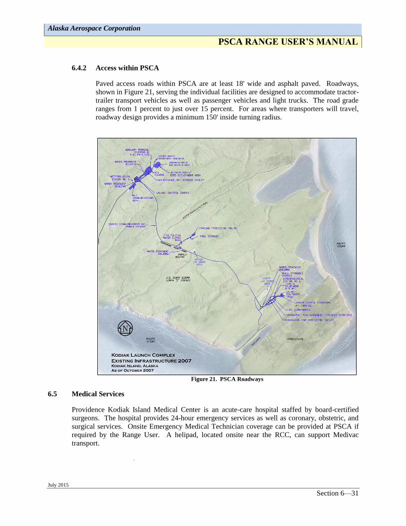
6.4.2 Access within PSCA
Paved access roads within PSCA are at least 18' wide and asphalt paved. Roadways,
shown in Figure 21, serving the individual facilities are designed to accommodate tractor-
trailer transport vehicles as well as passenger vehicles and light trucks. The road grade
ranges from 1 percent to just over 15 percent. For areas where transporters will travel,
roadway design provides a minimum 150' inside turning radius.
Figure 21. PSCA Roadways
6.5 Medical Services
Providence Kodiak Island Medical Center is an acute-care hospital staffed by board-certified
surgeons. The hospital provides 24-hour emergency services as well as coronary, obstetric, and
surgical services. Onsite Emergency Medical Technician coverage can be provided at PSCA if
required by the Range User. A helipad, located onsite near the RCC, can support Medivac
transport.
Alaska Aerospace Corporation
PSCA RANGE USER’S MANUAL
July 2015 Section 6—32
6.6 Industrial Shops
6.6.1 US Coast Guard (USCG)
The USCG installation has skilled aircraft maintenance and minor fabrication capability
for airframe, specialized welding, hydraulics, gas turbine engines, machining, sheet
metal, electrical, avionics, and marine electronics. The USCG has agreed to provide
selected services that cannot be obtained from local industry.
6.6.2 Local
Because Kodiak is one of the busiest fishing ports in the world, it has a broad-based
infrastructure that can provide local support for maintenance and repair.
6.7 Storage
PSCA has indoor storage space in the MSF, IPF, and PPF for launch related equipment.
Additional support, such as maintaining and staging equipment, enclosures, and environmentally-
controlled storage in excess of installed site systems may be negotiated. Exterior storage areas
are also available, but it is suggested that Range Users provide tarps or storage vans for
equipment stored outdoors.

Alaska Aerospace Corporation
PSCA RANGE USER’S MANUAL
July 2015 Section 7—33
SECTION 7 SUMMARY
7.1 Pacific Spaceport Complex Alaska Summary
Alaska Aerospace Corporation provides state-of-the-industry processing and launch facilities,
Range personnel, associated instrumentation, communications, clean rooms and support systems.
We are responsive and flexible to customer needs and priorities. Our schedule flexibility is
unmatched at any other Range, allowing our customers to not only meet their schedule, but also
their cost goals due to reduced delays and Range conflicts.
AAC is proud of our PSCA, our employees, and 100% success rate for our customers. Our
philosophy and approach is not to provide just a service to Range Users, but a partnership.
AAC’s goal is to make your mission successful no matter how hard or how complex.
We invite you to visit our corporate offices in Anchorage, Alaska or the PSCA in Kodiak, and let
AAC prove to you our commitment and our exceptional capabilities to support all types of launch
vehicles, missiles, targets and satellite missions.
7.2 Key Contact Information
Director of Range Operations:
Barry King: (256) 783-9454; [email protected]
Vice President of Business Development
Matt Steele: (661) 609-6661; [email protected]
Chief Engineer
Jeff Roberts: (907) 561-3338; [email protected]
Alaska Aerospace Corporation
4300 B Street, Suite 101
Anchorage, AK 99503
907-561-3338
www.akaerospace.com