P4K-HUL4E1 user manual 160821 - PARTILINK manual_160822.pdf · Table of Contents 1. INTRODUCTION 3...
53
P4K-HUL4E1 4K UHD HDMI & USB Over IP Extender P4K-HUL4E1-P 4K UDH HDMI & USB Over IP Extender with PoE P4K-HRSUL4E1 / P4K- LHRSU1E4 P4K-HRSUL4E1-P/ P4K-LHRSU1E4-P Partilink Technology Co., Ltd Copyright @2016 User manual
Transcript of P4K-HUL4E1 user manual 160821 - PARTILINK manual_160822.pdf · Table of Contents 1. INTRODUCTION 3...

P4K-HUL4E1 4K UHD HDMI & USB Over IP Extender
P4K-HUL4E1-P 4K UDH HDMI & USB Over IP Extender with PoE
P4K-HRSUL4E1 / P4K- LHRSU1E4 P4K-HRSUL4E1-P/ P4K-LHRSU1E4-P
Partilink Technology Co., Ltd Copyright @2016
User manual

Table of Contents
1. INTRODUCTION 3
2. FEATURES & APPLICATIONS 4
3. SPECIFICATION 5
4. HARDWARE DESCRIPTION 6
4.1 Transmitter 6
4.2 Receiver 8
5. INSTALLATION 10
5.1 Device Connection 10
5.2 IP Configuration 14
6. WEB USER INTERFACE CONFIGURATION 17
6.1 System 17
6.1.1 [Version Information] 17
6.1.2 [Update Firmware] 18
6.1.3 [Utilities] 20
6.1.4 [Statistics] 21
6.2 Video Wall 23
6.2.1 [Basic Setup] 23
6.2.2 [Advance Setup] 29

6.3 Network: Update the network setup of the
extender system 34
6.3.1 [IP Setup] 35
6.3.2 [Casting Mode] 36
6.4 Functions: 37
6.4.1 [Video over IP]: Setup the video output mode 38
6.4.2 [USB over IP]: Setup the USB extension mode 40
6.4.3 [Serial over IP]: set up the serial extension mode 41
7. BROADCAST CONFIGURATION SETTING 43
7.1 Multicast : 43
7.2 Unicast: 44
7.3 Matrix: 44
7.4 Video Wall: 45
7.4.1 [Basic Setup] 45
7.4.2 Advanced Setup 46
8. PACKAGE CONTENTS 51

Partilink Technology Co., Ltd Copyright @ 2017 3
1. INTRODUCTION
The 4K HDMI & USB over IP Extender is a solution for
audio, video and USB signal extension via Local Area
Network (LAN). It can be used as audio, video and
KVM extender over IP and applied to point to point,
point to multi-point, multi-point to multi-point and screen
wall broadcast system controlled by USB, RS-232, IR
and configured the 4K HDMI & USB over IP Extender
by web browser. An easy installation system built up
with Giga Ethernet switch which has IGMP function and
CATx cable for extension or broadcast. The
P4K-HUL4E1-P supports PoE (Power over Ethernet)
function.

Partilink Technology Co., Ltd Copyright @ 2017 4
2. FEATURES & APPLICATIONS � 4K HDMI over IP extension
� USB 2.0 over IP extension
� RS-232 bi-directional extension
� 4-bit DIP switch for 16 stream channel selection
� HDCP 1.4 compliant and Blu-Ray ready
� Support two-way IR extension
� Output video rotation
� Output video partial enlargement
� Automatic EDID configuration
� Networking environment under Giga Ethernet switch
and CATx cable
� Point to point extension, unicast, multicast and
screen wall system.
� Point to point extension via CAT5e cable without
Ethernet switch up to 100M
� Ethernet webpage management
� RS-232 Serial control command management
� P4K-HUL4E1-P supports Power over Ethernet

Partilink Technology Co., Ltd Copyright @ 2017 5
3. SPECIFICATION
P4K-HUL4E1 P4K-HUL4E1-P 4K UHD HDMI Over IP Extender
P4K-HRSUL4E1 P4K-HRSUL4E1-P Transmitter
P4K- LHRSU1E4 P4K-LHRSU1E4-P Receiver
VIDEO INPUT HDMI Type-A female connector None
VIDEO OUTPUT
HDMI Type-A female connector for loop through VGA DB-15 female local output
HDMI Type-A female connector
IR 2x 3.5mm phone jack for IR emitter and receiver to control video source device
COMPRESSION Visual lossless compression
HDMI INPUT RESOLUTION
3840x2160 30/24, 1080p 60/50, 1080p 30/25, 1080i 60 /50 720p 60/50, 480i 60/50, 480p 60/50
HDMI OUTPUT RESOLUTION
3840x2160 30/24, 1080p 30/25, 1080i 60/50,720p 60/5 0 480i 60/50, 480p 60/50
VGA OUTPUT RESOLUTION
1080p 30/25, 1080i 60/50, 720p 60/50 480i 60/50, 480p 60/50
AUDIO FORMAT Stereo 192Kbps
IP PROTOCOL TCP, UDP, RTSP, RTP, DHCP, IGMP, Multicast, IPV4
LAN PORT RJ45 connector for Giga Ethernet
SERIAL DB-9 male connector for RS-232 extension
MANAGEMENT LAN port None
Embedded webpage management HDMI Type-A female connector
POWER INPUT 2.0mm power jack for DC12V/2A input
OPERATING TEMPERATURE 0~55℃
OPERATING HUMIDITY 5%~90% RH
POWER SUPPLY Power adapter AC in 100~240V (50~60Hz)
ESD ESD protection air gap discharge ±8KV, contact discharged ±4KV
DIMENSION 194 x 114 x 28 mm
WEIGHT TX 620g, RX 610g
** Product specifications are subject to change without notice.

Partilink Technology Co., Ltd Copyright @ 2017 6
4. HARDWARE DESCRIPTION
4.1 Transmitter P4K-HUL4E1/ 4K-HUL4E1-P (TX)

Partilink Technology Co., Ltd Copyright @ 2017 7
1. 12 VDC power supply with locking for 4K HDMI &
USB over IP Extender.
2. RCA connector for stereo audio output.
3. RCA connector for stereo audio input.
4. HDMI video input connector
5. 10/100/1000 Mbps self-adaptive Ethernet interface.
6. ACT LED indicator turns green when 4K HDMI &
USB over IP Extender is powered up.
7. LINK LED indicator flickers green when network
connection is waiting for video source, turns green
when network connection and video source is
functioning properly
8. DB9 connector for RS-232 remote extension
9. Connect IR extension cable to IR port and position
the emitters near the devices you want to control
10. PC USB port for remote additional device such as
USB mouse, USB keyboard and USB pen drive
connecting to PC
11. Group configuration, 4-bit DIP switch to set up the
group ID
12. Restart the 4K HDMI & USB over IP extension by
pressing RESET button

Partilink Technology Co., Ltd Copyright @ 2017 8
13. Press EDID button for manual EDID copy function
14. DB9 connector for VGA local display
4.2 Receiver P4K-LHRSU1E4/ P4K-LHRSU1E4-P (RX)
Partilink Technology Co., Ltd Copyright @ 2017 9
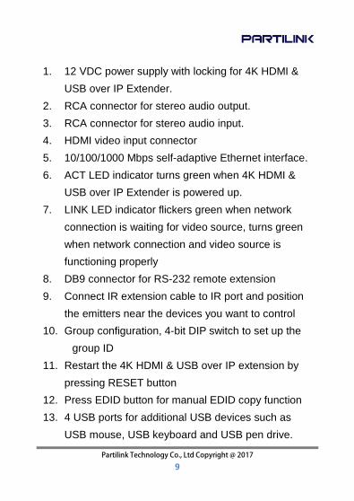
1. 12 VDC power supply with locking for 4K HDMI &
USB over IP Extender.
2. RCA connector for stereo audio output.
3. RCA connector for stereo audio input.
4. HDMI video input connector
5. 10/100/1000 Mbps self-adaptive Ethernet interface.
6. ACT LED indicator turns green when 4K HDMI &
USB over IP Extender is powered up.
7. LINK LED indicator flickers green when network
connection is waiting for video source, turns green
when network connection and video source is
functioning properly
8. DB9 connector for RS-232 remote extension
9. Connect IR extension cable to IR port and position
the emitters near the devices you want to control
10. Group configuration, 4-bit DIP switch to set up the
group ID
11. Restart the 4K HDMI & USB over IP extension by
pressing RESET button
12. Press EDID button for manual EDID copy function
13. 4 USB ports for additional USB devices such as
USB mouse, USB keyboard and USB pen drive.

Partilink Technology Co., Ltd Copyright @ 2017 10
Group Setting via 4-bit DIP switch
Setting the Transmitter and Receiver group ID via the 4-bit DIP
switch. The correspondent receivers are required to switch to
the same ID as the receiver. It can set up maximum 16 Group
IDs. Reboot the system to apply the group setting.
5. INSTALLATION
5.1 Device Connection
1. Check the power supply is unplugged.
2. Set up the group of the transmitter with the
correspondent receiver for signal extension and
display.
3. Connect the Transmitter to video source with HDMI
cable, and connect Receiver to a monitor or display
with HDMI cable.
4. Connect the USB cables from Transmitter to PC,
and connect the USB additional devices such as
USB mouse, USB keyboard and USB pen drive to
TX RX

Partilink Technology Co., Ltd Copyright @ 2017 11
Receiver.
5. Connect Transmitter and Receiver to the Ethernet
switch with network cable.
6. Power on the Transmitter, Receiver and all the
connected devices.
7. Power on and activate all the connected devices.
8. Connect the IR extension cable with Transmitter
and the IR receiver cable with Receiver for remote
control.
◆ Configuration

Partilink Technology Co., Ltd Copyright @ 2017 12
◆ Application Pattern
■ Unicast
■ Multicast a. Video Distribution

Partilink Technology Co., Ltd Copyright @ 2017 13
b. Matrix Distribution
c. Billboard & Kiosk, PC to HDMI and USB
Interactive Monitor

Partilink Technology Co., Ltd Copyright @ 2017 14
■ Screen Wall 5.2 IP Configuration
The 4K HDMI & USB Over IP Extender can configure via LAN in the same subnet.
1. Assign a LAN IP address to the computer in the
same subnet. The IP address default of the Transmitter and Receiver is B class Networking: 169.254.xxx.xxx.
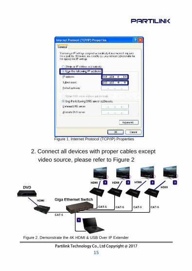
Partilink Technology Co., Ltd Copyright @ 2017 15
Figure 1. Internet Protocol (TCP/IP) Properties
2. Connect all devices with proper cables except video source, please refer to Figure 2
Figure 2. Demonstrate the 4K HDMI & USB Over IP Extender

Partilink Technology Co., Ltd Copyright @ 2017 16
Figure 3. Device IP Indication
3. After activation, the device information including the Transmitter and Receiver IP address will be shown in the lower right corner. Remember the Transmitter and Receiver IP address on monitor screen and then plug HDMI video source cable into Transmitter.
4. The administrator can input Transmitter or Receiver IP address into address bar of web browser to enter the Extender Web UI. If link success, administrator will see the Web UI as shown in Figure 4.

Partilink Technology Co., Ltd Copyright @ 2017 17
Figure4. Web User Interface
6. WEB USER INTERFACE CONFIGURATION
6.1 System
The relevant information of the connected extender and setting
6.1.1 [Version Information]
Indicating the firmware version and relevant information of the devices

Partilink Technology Co., Ltd Copyright @ 2017 18
Figure 5. Version Information of the Extender
6.1.2 [Update Firmware]
To update the firmware of the connected extender, please click on the [Select File] to select the firmware and click on [Upload] to upload the firmware and update accordingly.
Figure 6. Update Firmware
� Transmitter Firmware Update : please select

Partilink Technology Co., Ltd Copyright @ 2017 19
[webfw.bin] to update � Receiver Firmware Update : please select
[webfwc.bin] to update
It takes time to update the firmware. During the process of update, the Web user interface shows the status as below diagram. The extender system will reboot automatically after updating firmware. If it doesn’t reboot automatically, please reboot to apply the new firmware manually.
Figure 8. Firmware Update Progress
Figure 7. Select File to Update Firmware

Partilink Technology Co., Ltd Copyright @ 2017 20
Figure 9. Firmware Upgrade Complete and Reboot
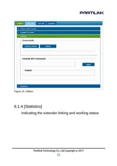
6.1.3 [Utilities]
There are some functions
� Factory Default :
Click on to return to the factory default when
necessary
� Reboot :
Click on to reboot the extender system
� Console API Command:
Input Linux command for advanced setting
Partilink Technology Co., Ltd Copyright @ 2017 21
Figure 10. Utilities
6.1.4 [Statistics]
Indicating the extender linking and working status

Partilink Technology Co., Ltd Copyright @ 2017 22
Figure 11. Statistics of Linking and Working Status

Partilink Technology Co., Ltd Copyright @ 2017 23
6.2 Video Wall
To set up the video wall application
6.2.1 [Basic Setup]
Figure 12. Basic Setup page

Partilink Technology Co., Ltd Copyright @ 2017 24
Bezel and Gap Compensation :
Dimension of the screen (inside and outside width and height)
OW: outside width OH: outside height VW: viewable width VH: viewable height
Please NOTE: 1) The viewable width must be less than the
outside width, and the viewable height must be less than the outside height.
2) If administrator doesn’t need this, just set all values to 0.
3) The unit is 0.1mm and the value MUST be integer.
Figure 13. Monitor Bezel and Gap Setup

Partilink Technology Co., Ltd Copyright @ 2017 25
� Wall Size and Position Layout :
Select number of vertical and/ or horizontal monitors, row position and column position. Vertical monitor number 1~8, horizontal monitor number 1~16
Figure 14. Vertical Monitor Number Setup
Figure 15. Horizontal Monitor Number Setup

Partilink Technology Co., Ltd Copyright @ 2017 26
Figure 16. Column Position Setup
� Preferences :
Select the video fit in the screen or stretch out and the rotate angle
Figure 17. Video Stretch or Fit Screen Setup

Partilink Technology Co., Ltd Copyright @ 2017 27
Figure 19. Monitor Setting Application
Figure 18. Video Rotation Angle Setup
� Apply To:
1) All: Configure all Transmitter and Receiver in
the same Group IP.
2) This (Local): The IP you input into address bar of web browser.
3) Hosts or Clients: select which Transmitter or Receiver you want to configure.
Partilink Technology Co., Ltd Copyright @ 2017 28
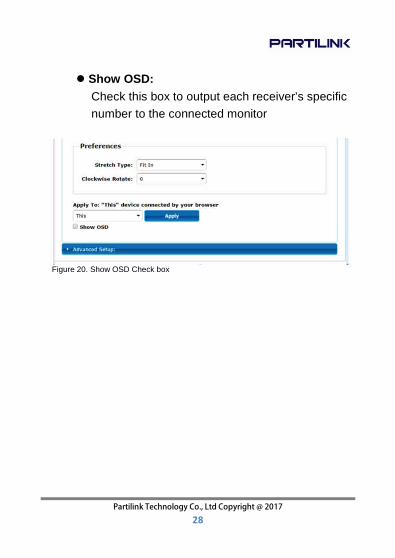
� Show OSD:
Check this box to output each receiver’s specific number to the connected monitor
Figure 20. Show OSD Check box

Partilink Technology Co., Ltd Copyright @ 2017 29
6.2.2 [Advance Setup]
Figure 21. Video Wall Advanced Setup
Partilink Technology Co., Ltd Copyright @ 2017 30
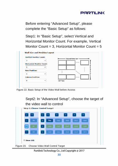
Before entering “Advanced Setup”, please complete the “Basic Setup” as follows:
Step1: In “Basic Setup”, select Vertical and Horizontal Monitor Count. For example, Vertical Monitor Count = 3, Horizontal Monitor Count = 5
Sept2: In “Advanced Setup”, choose the target of the video wall to control
Figure 23. Choose Video Wall Control Target
Figure 22. Basic Setup of the Video Wall before Access

Partilink Technology Co., Ltd Copyright @ 2017 31
If user make incorrect operations, press “Reset” in Reset to Basic Setup function.
Figure 24. Reset to Basic Setup
Setup the video output to “Fit In’ or “Stretch Out” mode in the screen
Figure 25. Video Stretch Type
Setup the rotation angle of the video output
Figure 26. Clockwise Rotate
Set up the number of vertical and horizontal monitor based on the video wall layout. Vertical number 1~8 and horizontal number 1~16. Setup the row postion of monitor, number from 0 to the total number of vertical monitor.

Partilink Technology Co., Ltd Copyright @ 2017 32
Figure 27. Setup the Vertical and Horizontal Number of Monitor
Setup the column position of monitor, number from 0 to the total number of horizontal monitor.
Figure 28. Seup the Row Position of the Monitor
Figure 29. Setup Column Position of the Monitor

Partilink Technology Co., Ltd Copyright @ 2017 33
Setup the video position shift and video enlarge.
� Horizontal Shift: Setup the video horizontal shift,
Left or Right � Vertical Shift : Setup the video vertical shift, Up
or Down � Horizontal Scale Up : Setup the video horizontal
scale up. � Vertical Shift Scale Up : Setup the video vertical
scale up.
Figure 30. Output Video Adjustment
� Consol API Command : Input Linux command to
do advanced setup.

Partilink Technology Co., Ltd Copyright @ 2017 34
Figure 31. Consol API Command Input
6.3 Network: Update the network setup of the
extender system
Figure 32. Network Setup

Partilink Technology Co., Ltd Copyright @ 2017 35
6.3.1 [IP Setup]
� Auto IP : use automatically Extender assign IP
system for example: 169.254.xxx.xxx
� DHCP: use the DHCP of the external device
such as the IP sharer to assign IP
Figure 34. DHCP
Figure 33. Auto IP Setup

Partilink Technology Co., Ltd Copyright @ 2017 36
� Static : use the static IP to assign manually
Figure 35. Assign Static IP
6.3.2 [Casting Mode]
Select the broadcast mode of the extender
application
� Multicast: point to multiple points or multiple
point to multiple points broadcast � Unicast: point to point broadcast
Figure 36. The Casting Mode Setup

Partilink Technology Co., Ltd Copyright @ 2017 37
6.4 Functions :
Setup the video output and USB extension mode
Figure 37. Video and USB over IP Functions

Partilink Technology Co., Ltd Copyright @ 2017 38
6.4.1 [Video over IP]: Setup the video output mode
� Enable Video over IP: Check to enable video
extension over IP
� Enable Video Wall: Check to enable the video
extension for building up video wall
� Enable EDID Copy: This function is limited to
copy one of the receivers.
� Scaler Output Mode:
Select the required scalar output mode or select
“customize” and input 8 Hex values for more
video output resolution and refresh rate
selections.
1) 80000004: HD 720p60 2) 81000061: WXGA 1366x768@60 3) 81000040: WXGA+ 1440x900@60 4) 81000051: WUXGA 1920x1200@60 5) 8100003C: SXGA+ 1400x1050@60
� Timeout for Detecting Video Lost: Setup the
time of stop the video storage when detecting
video lost to transmit

Partilink Technology Co., Ltd Copyright @ 2017 39
Figure 38. Video over IP Setup
Figure 39. Customize Scaler Output Mode

Partilink Technology Co., Ltd Copyright @ 2017 40
6.4.2 [USB over IP]: Setup the USB extension
mode
� Enable USB over IP: Check to enable USB
extension mode over IP
� Operation Mode: Including “auto select mode”,
“active on line” and “active per request” modes
for option.
� Compatibility Mode: Check to enable USB
keyboard, USB mouse transmission mode.
Figure 40. Timeout for Detecting Video Lost

Partilink Technology Co., Ltd Copyright @ 2017 41
6.4.3 [Serial over IP]: set up the serial extension
mode
� Select Type 2 as operation mode
� Set up the baud rate for Type 2.
Figure 41. USB over IP Functions

Partilink Technology Co., Ltd Copyright @ 2017 42
Figure 42. Serial over IP
Figure 43. Broadcast Mode Setting

Partilink Technology Co., Ltd Copyright @ 2017 43
7. BROADCAST CONFIGURATION SETTING
There are some examples to show the setup for
unicast, multicast, matrix and video wall.
Broadcast setting including unicast and multicast
7.1 Multicast :
To enable the USB interactive devices controlled by turns, please check “Auto select USB operation mode per casting mode”
Figure 44. USB Interaction Application

Partilink Technology Co., Ltd Copyright @ 2017 44
7.2 Unicast:
7.3 Matrix:
Install multiple transmitters and setting ID of these transmitters individually, edit the group of transmitters and receivers. The correspondent receivers will output the video from the transmitter belonged to the same group ID.
Figure 46. Transmitter and Receiver Unit Grouping
Figure 45. Unicast Application

Partilink Technology Co., Ltd Copyright @ 2017 45
7.4 Video Wall:
A 3x5 (row x column) video wall setting example here for reference. In multicast and matrix application mode, access the Web user interface of correspondent receiver to setup
7.4.1 [Basic Setup]
Please refer to “Section 6.2.1 Basic setup” and
follow the steps as below.
Figure 47. Multicast Application

Partilink Technology Co., Ltd Copyright @ 2017 46
Step1: Set up the vertical monitor count to “3”
Step2: Set up the horizontal monitor count to “5”
Step3: Set up the row position of the monitor to
0
Step4: Set up the column position to 0
Step5: Apply the setting to the extender system
Administrator can complete each Extender position setting after following 5 steps in above. And then follow the above steps to set the other Extenders to the rest of row and column positions from 0x1, 0x2, 0x3 to 3x5. After the basic setup of the video wall, please access the advanced setup to proceed other detailed setting of the video output
7.4.2 Advanced Setup Select the monitor you want to control. The one you select will show “This” in green in video wall matrix layout. Take below diagram for example, the monitor we select to control here is the

Partilink Technology Co., Ltd Copyright @ 2017 47
monitor in the upper left corner.
Figure 53. Example for the Video Wall Control
Here’s the diagram of the actual video wall layout showing the selected monitor in the upper left corner with green outline.
Figure 54. Example for the Video Wall Control

Partilink Technology Co., Ltd Copyright @ 2017 48
Return to the previous setup of video wall quickly when incorrect operation was input.
Figure 55. Reset Adjust the horizontal position of the video output, “Left/ Right Shift”, the selected monitor to adjust is shown with green outline.
.
Adjust the vertical position of the video output, “Up/ Down Shift”, the selected monitor to adjust is shown with green outline.
Figure 56. Example for Adjust the Monitor of Video Wall

Partilink Technology Co., Ltd Copyright @ 2017 49
Horizontal Scale Up: To scale up the video
output horizontally as the monitor shown with green outline
Figure 57. Example for Adjust the Monitor of Video Wall
Figure 58. Example for Adjust the Monitor of Video Wall

Partilink Technology Co., Ltd Copyright @ 2017 50
Vertical Scale Up: To scale up the video output
vertically as the monitor shown with green outline
Figure 59. Example for Adjust the Monitor of Video Wall

Partilink Technology Co., Ltd Copyright @ 2017 51
8. PACKAGE CONTENTS
1. P4K-HRSUL4E1 / P4K-HRSUL4E1-P HDMI &
USB extender over IP transmitter (1)
2. P4K-LHRSU1E4 / P4K-LHRSU1E4-P HDMI &
USB extender over IP receiver (1)
3. DC12V 2A power adapter, one comes with the
transmitter P4K-HRSUL4E1 (1) and one comes with
receiver P4K-LHRSU1E4 (1). Please NOTE: The
standard package of PoE model doesn’t include
power adapter.
4. IR receiver cable comes with receiver (1)
5. IR emitter cable comes with transmitter (1)
6. User manual (1)
7. Rear bracket (2)

www.partilink.com


![Psalm 119.pptx [Read-Only] Thess/160821... · 2016. 8. 19. · PSALM 119 Nun 105 Thy word is a lamp unto my feet, and a light unto my path. 106 I have sworn, and I will perform it,](https://static.fdocuments.in/doc/165x107/607d5ed6babf584f653e0796/psalm-119pptx-read-only-thess160821-2016-8-19-psalm-119-nun-105-thy.jpg)