
P€¦ · PST (Pacific Standard Time) ... tor’s power or engine and disconnecting drive battery....
16
OPERATING INSTRUCTION Please read this manual thoroughly. Keep this manual in a convenient place for quick and easy reference. No. 33400 www.graupner.com
Transcript of P€¦ · PST (Pacific Standard Time) ... tor’s power or engine and disconnecting drive battery....

OPERATING INSTRUCTION
Please read this manual thoroughly.
Keep this manual in a convenient place for quick and easy reference.
No. 33400
www.graupner.com

- Contents -
◎ Before use
◎ Support and Service
Customer Support
Online Support
A/S support & Warranty information
◎ OPENHOBBY A/S SUPPORT AND SERVICE CENTER
◎ Box Contents
◎ Safety Warning Notes
◎ System Features
◎ Specification
◎ Product Description
◎ HoTT
◎ Operation
◎ Receiver installation
◎ Steering & Trigger tension adjustment
◎ Steering wheel position adjustment
◎ Trigger Angle Adjustment
◎ Installation for left-handed users
◎ Binding and Range test
◎ Control Switch Functions
◎ Fail Safe mode Configuration
◎ Trigger and Steering Calibration
◎ LED and Buzzer Indication
◎ Receiver port Description
◎ Smart Box (Configuration by Telemetry)
◎ The Guide for the related Countries’ Certifications
◎ Environmental Protection Notes
4
4
4
4
4
4
5
5
6
6
6
7
7
8
8
8
8
9
10
10-11
11
11
12
12-14
14-15
15-16
16
3
◎ BEFORE USE
◎ SUPPORT AND SERVICE ◎ OPENHOBBY A/S CENTER
Thank you for purchasing Graupner/SJ X-4S HoTT 2.4GHz Radio
System. This system is extremely versatile and may be used by
beginners and pros alike. In order for you to make the best use
of your system, please read this manual carefully. If you have any
difficulties while using your system, please consult the manual, our
online Frequently Asked Questions (on the web pages referenced
below), your hobby dealer, or the Graupner/SJ Service Center.
Due to unforeseen changes in production procedures, the informa-
tion contained in this manual is subject to change without notice.
4
Customer support
We are happy to assist you with any question by e-mail
or phone. Customer service hours are from 9 am to 5 pm
PST (Pacific Standard Time) during the workweek, Monday
through Friday. E-mailed questions will be answered as
soon as possible
A/S support
During the warranty period, we can repair this product at
no cost in the event that it has become faulty under nor-
mal operating conditions.
For non-functional products that are past the expiration
date of the warranty or have been improperly used, we
would be happy to repair this product for an appropriate
amount of cost to the consumer.
Online Support
Please visit us at www.openhobbby.com, to stay up to
date with the latest software, firmware and product infor-
mation.
Warranty information
Refer the WARRANTY CARD in the Package
3245 University Ave, Suite 1520, San Diego, CA 92104,
United States of America
Phone: +1 855-5-RCisHoTT ( +1 855-572-4746)
Fax: +1 855-546-0350
E-mail: [email protected]
©2014 Graupner/SJ USA – OPENHOBBY LLC. The HoTT trademark is used with permission of SJ Inc. 4386066

◎ BOX CONTENTS
◎ SAFETY WARNING NOTES
1. X-4S HoTT Transmitter
2. Warranty Card
3. GR-4 Receiver
4. Temperature / Voltage Sensor (S8362)
5. Battery Holder
6. Alkaline 4 cells
7. Manual
5
• Never operate your car or truck in a crowded street with traf-
fic. Especially, do not drive in a place near railway, chemical
substance, gas to prevent any damage.
• This product is not intended for use by inexperienced or dis-abled person without direct supervision of a responsible, knowl-
edgeable adult. This is not suitable for children under 18 years.
• This warranty does cover damaged products arising as a result
of production process. It is not allowed to use to those who are
the disabled or do not have enough knowledge.
• The radio system is affected by signal environment and the
electronic jamming signals can cause disorientation and loss of
control of your aircraft.
• Please read the manual to make the best use of the product
• Make sure to check all operations of channels before use.
• For the safe use, please operate the Range Check Mode be-
fore use.
• Be careful not to turn your transmitter off while in use.
• Do not touch or grab antenna during the use.
• Do not operate your model in the rain or run through standing
water
• Fail Safe should be set before use to prevent uncontrollable situation occurred by any interruption.
It is recommended to set throttle channel to Neutral condition
or brake condition.
• Always operate your program setup mode after stopping mo-
tor’s power or engine and disconnecting drive battery.
• Make sure whenever you start operating your transmitter, turn
your transmitter before switching your receiver switch. Whenev-
er you stop your transmitter, turn your receiver off before your
transmitter is switched off.
• Always use new battery pack or charge your battery fully to
avoid possible hazard causing by low battery capacity.
• Always be sure to check your battery capacity for your trans-
mitter and receiver.
• As for boat model, we recommend installing your antenna ver-
tically to the exterior boat and operating Range Check Mode for
the best use of your model.
◎ Specifications
◎ Product description (Mechanical Parts)
◎ Specifications
1. HOPPING TELEMETRY TRANSMISSION (HoTT)The use of up to 35 hopping channels provides advanced reliable operation while keeping from any external interference.
2. Designed for beginners, X-4S HoTT Transmitter is the best choice for those who enjoy car, boat, and tank models. When optional Graupner/SJ Telemetry sensor or temperature sensor is used, you may check the real-time information such as model voltage, user programmable warnings. It is easy to check from your transmitter.
3. Unlike other binding systems which are widely used, X-4S HoTT Transmitter supports the fast binding system which is operated by
pressing a button.
6
(1) X-4S Transmitter
(2) GR-4 Receiver
Channel
Operating Voltage
Battery Type
Operating Current
Operating Output Power
Frequency
Modulation
Operating Temperature
Antenna
Display
Low voltage warning alarm
High temp warning alarm
Battery Charging
Firmware Update
Size
Weight
Channel
Frequency
Modulation
Operating Voltage
Operating Output Power
Operating Current
Display
Firmware update
Fail Safe
Temperature Sensor Warning
Low voltage warning alarm
Telemetry Sensor
Size
Weight
2CH
4.8 ~ 6.0V
Alkaline, Nixx 4 Cell
app. 65mA
App. 60 mW
2.4000 ~ 2.4835 GHz
FHSS
app. -10 ~ +55`C ( app. -50 ~ +131℉ )
Dipole Antenna
LED Indicator
available (LED, Buzzer)
available (LED, Buzzer)
DC Jack
available (Futaba 3p connector)
171.1 x 292.0 x 139.8 mm (6.74 x 11.49 x 5.50 in)
365.7g (12.89oz)
2 CH
2400~2483.5 MHz
FHSS
3.6~8.4V
60mW
35.0mA
One LED (red)
available (Port3)
Free/Fail safe
(T/V Connector) Port4 (50~150℃)
(T/V Connector) Port4 (1.0~25.5V)
(B/T Connector) Port3
30x21x14.3 mm (1.18x0.82x0.56 in)
app. 5.5g (0.19oz)
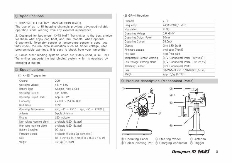
②
①
④
⑤
⑥
③
① Operating Panel ② Steering Wheel ③ Antenna④ Communicating Port ⑤ Charging connector ⑥ Trigger

◎ HoTT (Hopping Telemetry Transmission)
◎ Operation
The use of up to 35 hopping channels provides advanced reliable
operation while keeping from any external interference. This HoTT
radio system gives user real-time information on various useful
data such as user model’s RPM, voltage, temperature, user pro-
grammable warning, and so on.
X-4S HoTT Transmitter comes with GR-4 2Ch receiver.
7
Battery Connection
- Only use optional manganese dry battery or NiCd /NiMH
1.2volt, individual AA size rechargeable battery. (LiPo bat-
tery must not be used.)
- Remove the cover and install your battery to battery
socket. Then, replace the cover making sure it is closed
securely.
- When low voltage warning alarm is activated, please use
new battery or recharge the used battery.
Please make sure the correct polarity when installing your
battery.
Battery Charging
If rechargeable battery is in use, you can charge it up to
150mA with optional charging adapter.
We may notice that little heating will be occurred during
use, which means it is working properly. Now that this
product features 4 cell battery packs, it is allowed to use
within its specification. Otherwise, it may cause damage to
your model.
※Cautions
Reference picture (Correct polarity)
The improper use will cause fire. So please keep the
safety rules. Low-voltage warning for transmitter battery
Please charge Alkaline 4 cell or Nixx 4 cell battery before
use. When it will beep continuously due to low voltage
warning, please stop an operation, then recharge your
battery or replace it.
(Do not use Lixx battery and please only use Alkaline or
Nixx battery.)
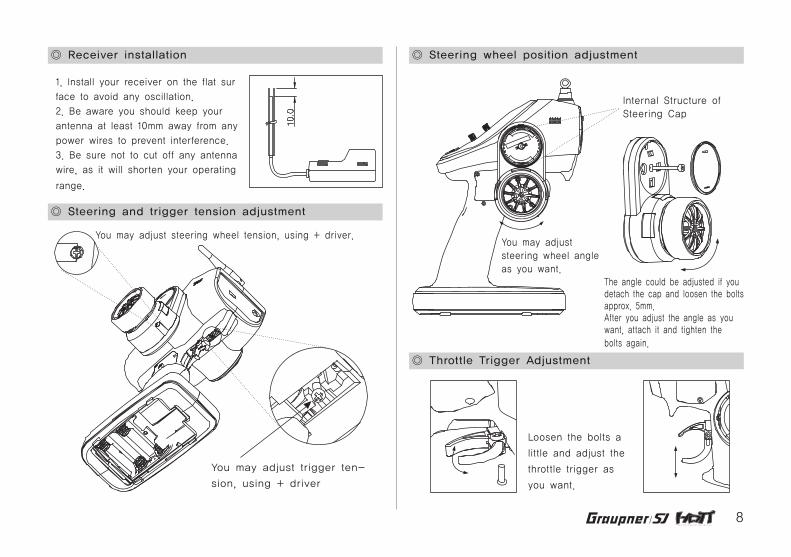
◎ Receiver installation
◎ Steering and trigger tension adjustment
1. Install your receiver on the flat sur
face to avoid any oscillation.
2. Be aware you should keep your
antenna at least 10mm away from any
power wires to prevent interference.
3. Be sure not to cut off any antenna
wire, as it will shorten your operating
range.
8
You may adjust trigger ten-
sion, using + driver
You may adjust steering wheel tension, using + driver.
◎ Steering wheel position adjustment
◎ Throttle Trigger Adjustment
The angle could be adjusted if you detach the cap and loosen the bolts approx. 5mm. After you adjust the angle as you want, attach it and tighten the bolts again.
You may adjust steering wheel angle as you want.
Loosen the bolts a
little and adjust the
throttle trigger as
you want.
Internal Structure of Steering Cap
9
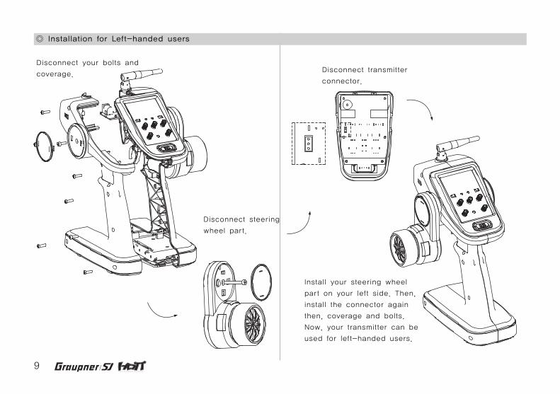
◎ Installation for Left-handed users
Disconnect your bolts and
coverage.
Disconnect steering
wheel part.
Disconnect transmitter
connector.
Install your steering wheel
part on your left side. Then,
install the connector again
then, coverage and bolts.
Now, your transmitter can be
used for left-handed users.
10
◎ Binding & RF Range Test
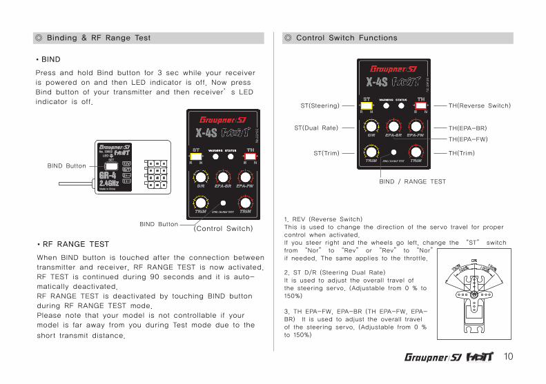
BIND
Press and hold Bind button for 3 sec while your receiver
is powered on and then LED indicator is off. Now press
Bind button of your transmitter and then receiver’s LED
indicator is off.
(Control Switch)
RF RANGE TEST
When BIND button is touched after the connection between
transmitter and receiver, RF RANGE TEST is now activated.
RF TEST is continued during 90 seconds and it is auto-
matically deactivated.
RF RANGE TEST is deactivated by touching BIND button
during RF RANGE TEST mode.
Please note that your model is not controllable if your
model is far away from you during Test mode due to the
short transmit distance.
◎ Control Switch Functions
1. REV (Reverse Switch)This is used to change the direction of the servo travel for proper control when activated.If you steer right and the wheels go left, change the “ST” switch from “Nor” to “Rev” or “Rev” to “Nor”if needed. The same applies to the throttle.
2. ST D/R (Steering Dual Rate)It is used to adjust the overall travel of the steering servo. (Adjustable from 0 % to 150%)
3. TH EPA-FW, EPA-BR (TH EPA-FW, EPA-BR) It is used to adjust the overall travel of the steering servo. (Adjustable from 0 % to 150%)
ST(Steering)
ST(Dual Rate)
ST(Trim)
BIND Button
BIND Button
BIND / RANGE TEST
TH(Reverse Switch)
TH(EPA-BR)
TH(Trim)
TH(EPA-FW)

11
◎ Fail Safe Mode Configuration
◎ Trigger and Steering Calibration
It should be programmed after binding
process. The default value is “Free”
mode.
Fail Safe is set to throttle channel (CH2)
Move your throttle to the position on
which you act fail safe mode. Now touch
and hold BIND button for 3 sec until fail
safe mode is set. (Buzzer beeps 3 times)
Press BIND button for 3 sec again and
fail safe is deactivated. Now return to
“Free” mode. (Buzzer beeps twice)
After returning to Free mode, turn your
transmitter off so that Fail safe mode is
acting properly.
While pressing BIND button, turn your
transmitter on.
Press BIND button for 5 sec until your
transmitter beeps twice and it is re-
turned to Calibration Model.
Move steering and throttle to back and
forward, left and right, then move to
neutral position again. Now your trans-
mitter beeps twice, indicating Calibration
Setup is now set.
4. TRIM
The trims are used to fine-tune the point
where the servo returns to center.
(Adjustable from -37.5% to +37.5%)
ST- Use the ST-TRIM so your vehicle will go
perfectly straight when the steering wheel is
centered. (Adjustable from -37.5% to +37.5%)
TH- Use the THR-TRIM to adjust the amount
of brake that occurs when your engine’s idle
is too low or high and your ESC is not per
fectly at neutral.
(Adjustable from -37.5% to +37.5%)
Electric model’s Fail safe position
(Neutral)
Engine model’s Fail safe position
(Brake)
(Control Switch)
(Control Switch)
BIND Button
BIND Button
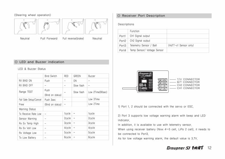
<Steering wheel operation>
Neutral Full left Full right Neutral
12
<Steering wheel operation>
◎ LED and Buzzer indication
◎ Receiver Port Description
LED & Buzzer Status
Descriptions
RX BIND ON
RX BIND OFF
Fail Safe Setup/Cancel
Free
Warning Status
Tx Receive Rate Low
Sensor Warning
Rx Ex Temp High
Rx Ex Volt Low
Rx Voltage Low
Tx Low Battery
Range TEST
Bind Switch
Push
-
Push
(Bind on status)
Push 3sec
(Bind on status)
-
-
-
-
-
-
RED
-
-
GREEN
ON
Slow flash
Buzzer
-
-
1cycle
2cycle
3cycle
4cycle
5cycle
6cycle
1cycle
2cycle
3cycle
4cycle
5cycle
6cycle
-
-
-
-
-
-
- Slow flash Low 2Time(90sec)
-
-
Low 3Time
Low 2Time
Port1
Port2
Port3
Port4
Function
Ch1 Signal output
Ch2 Signal output
Telemetry Sensor / Batt
Temp Sensor/ Voltage Sensor
(HoTT-v1 Sensor only)
Neutral NeutralFull Forward Full reverse(brake)
T/V CONNECTORB/T CONNECTORCH2 CONNECTORCH1 CONNECTOR
1) Port 1, 2 should be connected with the servo or ESC.
2) Port 3 supports low voltage warning alarm with beep and LED
indicator.
In addition, it is available to use with telemetry sensor.
When using receiver battery (Nixx 4~5 cell, LiPo 2 cell), it needs to
be connected to Port3.
As for low voltage warning alarm, the default value is 3.7V.
4) Receiver Indicator LED’s
LED OFF: Very good signal condition
LED blinks: Not good signal condition
LED ON: No signal
13
※Caution: Warning alarm may not be activated, depending on
weather condition or mounting location.
If it is not activated, change mounting location or adjust temperature
value with optional smart box (Telemetry box). (Default value: 100℃)
Caution: For your safe use, we recommend fully charging your bat-
tery before use.
Warning alarm function is automatically activated when your battery
capacity is lower than 70%, regardless of power battery’s charging
status.
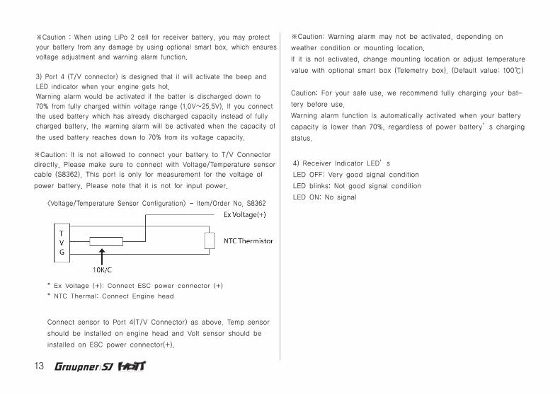
<Voltage/Temperature Sensor Configuration> - Item/Order No. S8362
※Caution : When using LiPo 2 cell for receiver battery, you may protect
your battery from any damage by using optional smart box, which ensures
voltage adjustment and warning alarm function.
3) Port 4 (T/V connector) is designed that it will activate the beep and
LED indicator when your engine gets hot.
Warning alarm would be activated if the batter is discharged down to
70% from fully charged within voltage range (1.0V~25.5V). If you connect
the used battery which has already discharged capacity instead of fully
charged battery, the warning alarm will be activated when the capacity of
the used battery reaches down to 70% from its voltage capacity.
※Caution: It is not allowed to connect your battery to T/V Connector
directly. Please make sure to connect with Voltage/Temperature sensor
cable (S8362). This port is only for measurement for the voltage of
power battery. Please note that it is not for input power.
* Ex Voltage (+): Connect ESC power connector (+)
* NTC Thermal: Connect Engine head
Connect sensor to Port 4(T/V Connector) as above. Temp sensor
should be installed on engine head and Volt sensor should be
installed on ESC power connector(+).

14
◎ Smart Box (Configuration by Telemetry)
The use of optional smart box supports easy configuration.
When operating in SETTING & DATA VIEW mode in telemetry box,
the screen appears as follows.
RECEIVER 0.01 >>AL RX-V(5.1V) : 3.7V AL RX-T(+33`c): 65`C PERIOD : 10ms AL EX-V( 7.4V): AUTO AL EX-T( 27`C):100`C
Electric & Engine model configuration
Red wire sensor cable
ESC
Connect a battery to red cable(+)
Battery connection
Motor connection
Power switch
Temperature sensor
Connect temperature sensor to Engine head
Steering Servo
Receiver battery
Throttle Servo
Steering Servo
T/V Connector
T/V Connector
B/T Connector
CH2 Connector
CH1 Connector
CH2 Connector
CH1 Connector
<Electric model Configuration>
<Engine model Configuration>
Smart Box (#33700)
1. ALARM VOLT
It is used for low battery warning program. (Adjustable from 3.5V to
8.0V)
The default value is 3.7V.
2. ALARM TEMP
It is used for receiver’s warning program (Adjustable from 30℃ to
80℃)
The default value is 65℃
3. PERIOD
It is used to set the speed of receiver’s output signal. (Selectable
10msec or 20msec)
15
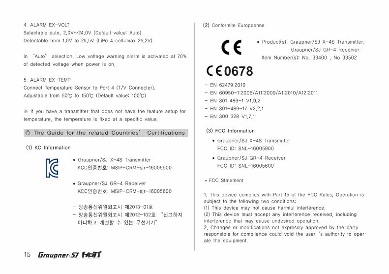
(1) KC Information
Graupner/SJ X-4S Transmitter
KCC인증번호: MSIP-CRM-sjr-16005900
Graupner/SJ GR-4 Receiver
KCC인증번호: MSIP-CRM-sjr-16005600
- 방송통신위원회고시 제2013-01호
- 방송통신위원회고시 제2012-102호 “신고하지
아니하고 개설할 수 있는 무선기기”
- EN 62479:2010
- EN 60950-1:2006/A11:2009/A1:2010/A12:2011
- EN 301 489-1 V1.9.2
- EN 301-489-17 V2.2.1
- EN 300 328 V1.7.1
Product(s): Graupner/SJ X-4S Transmitter,
Graupner/SJ GR-4 Receiver
Item Number(s): No. 33400 , No 33502
Graupner/SJ X-4S Transmitter
FCC ID: SNL-16005900
Graupner/SJ GR-4 Receiver
FCC ID: SNL-16005600
(2) Conformite Europeenne
(3) FCC Information ◎ The Guide for the related Countries’ Certifications
4. ALARM EX-VOLT
Selectable auto, 2.0V~24.0V (Default value: Auto)
Detectable from 1.0V to 25.5V (LiPo 4 cell=max 25.2V)
In “Auto” selection, Low voltage warning alarm is activated at 70%
of detected voltage when power is on.
5. ALARM EX-TEMP
Connect Temperature Sensor to Port 4 (T/V Connecter).
Adjustable from 50℃ to 150℃ (Default value: 100℃)
※ If you have a transmitter that does not have the feature setup for
temperature, the temperature is fixed at a specific value.
• FCC Statement
1. This device complies with Part 15 of the FCC Rules. Operation is subject to the following two conditions:(1) This device may not cause harmful interference.(2) This device must accept any interference received, including interference that may cause undesired operation.2. Changes or modifications not expressly approved by the party responsible for compliance could void the user‘s authority to oper-ate the equipment.
0678
16
This product must not be disposed of with other waste.
Instead, it is the user’s responsibility to their waste
equipment by handing it over to a designated collection
point for the recycling of waste electrical and
electronic equipment. The separate collection and recycling
of your waste equipment at the time of disposal will help to conserve
natural resources and
ensure that it is recycled in a manner that protects human health and
the environment. For more
information about where you can drop off your waste equipment for
recycling, please contact your
local city office, your household waste disposal service or where you
purchased the produce
◎ ENVIRONMENTAL PROTECTION NOTES• NOTE
This equipment has been tested and found to comply with the limits
for a Class B digital device, pursuant to Part 15 of the FCC Rules.
These limits are designed to provide reasonable protection against
harmful interference in a residential installation. This equipment
generates uses and can radiate radio frequency energy and, if not
installed and used in accordance with the instructions, may cause
harmful interference to radio communications. However, there is no
guarantee that interference will not occur in a particular installation.
If this equipment does cause harmful interference to radio or televi-
sion reception, which can be determined by turning the equipment
off and on, the user is encouraged to try to correct the interference
by one or more of the following measures:
- Reorient or relocate the receiving antenna.
- Increase the separation between the equipment and receiver.
- Connect the equipment into an outlet on a circuit different from
that to which the receiver is connected.
- Consult the dealer or an experienced radio/TV technician for
help.
• FCC radiation exposure statement
This equipment complies with FCC radiation exposure limits set forth
for an uncontrolled environment. This equipment should be installed
and operated with minimum distance of 20 cm between the radiator
and your body.


