Oxy-Fuel Instruction Manual - American Torch...
53
Oxy-Fuel Instruction Manual Setup and operation safety instructions for cutting, heating, welding and brazing equipment Read operating instructions before use.
Transcript of Oxy-Fuel Instruction Manual - American Torch...
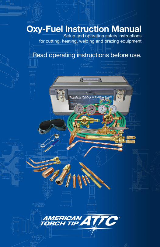
Oxy-Fuel Instruction Manual Setup and operation safety instructions
for cutting, heating, welding and brazing equipment
Read operating instructions before use.

Table of Contents
Introduction ...................................................................................................1SECTION 1: General Safety Information .....................................................2
The Work Area ................................................................................................ 2Protective Apparel .......................................................................................... 2Fire Prevention ............................................................................................... 2
SECTION 2: Industrial Gases .......................................................................3Oxygen ........................................................................................................... 3Acetylene ........................................................................................................ 4MAPP® Gas ................................................................................................... 6Natural Gas and Propane ............................................................................... 6Natural Gas and Propane Cylinders ............................................................... 6Natural Gas .................................................................................................... 6Propane .......................................................................................................... 6Propylene and Propylene Based Fuel Gases ................................................. 7Fuel Gases with Natural Gas or Propane Base ............................................. 8
SECTION 3: Oxy-Fuel Apparatus .................................................................9Oxygen and Fuel Supply ................................................................................ 9Regulators ...................................................................................................... 9Gas Hoses .................................................................................................... 10Torch Handle ................................................................................................ 11Flashback Arrestors ..................................................................................... 12Preheat Oxygen Control Valve ..................................................................... 13Cutting Tip .................................................................................................... 14Welding Nozzle ............................................................................................. 15Multi-Flame Heating Nozzles ....................................................................... 16
SECTION 4: Setting Up Equipment for Welding ........................................17Cylinders ...................................................................................................... 17Regulators .................................................................................................... 18Torch Handle ................................................................................................ 22Welding Nozzle ............................................................................................. 23Multi-Flame Heating Nozzles ....................................................................... 24Leak-Testing the System .............................................................................. 24Setting Up to Weld, Lighting the Torch and Adjusting the Flame ................ 25
SECTION 5: Welding Procedures ..............................................................28Preparing the Metals to be Welded .............................................................. 28Forehand and Backhand Welding Techniques ............................................. 29Starting and Finishing the Weld ................................................................... 30When You Finish Your Welding Operation .................................................... 32Oxy-Fuel Brazing and Braze Welding........................................................... 33Preparing the Metals to be Brazed............................................................... 33Setting Up for Brazing Applications ............................................................. 33Brazing Sheet Steel ...................................................................................... 33When You Finish Your Brazing Operation .................................................... 34

IllustrationsFigure 1, Aceteylene Cylinder Interior ................................................................... 4Figure 2, Regulator Parts....................................................................................... 9Figure 3, Torch Handle Parts ............................................................................... 11Figure 4, Flashback Arrestor ............................................................................... 12Figure 5, Cutting Attachment Parts ..................................................................... 13Figure 6, Cutting Tip ............................................................................................ 14Figure 7, Welding Nozzle ..................................................................................... 15Figure 8, Securing the Cylinders ......................................................................... 17Figure 9, Inspecting the Cylinder and Cylinder Valve .......................................... 18Figure 10, Cracking the Cylinder Valve ............................................................... 18Figure 11, Tightening the Regulator .................................................................... 19Figure 12, Opening the Cylinder Valve ................................................................ 20Figure 13, Torch Mount Check Valves and Flashback Arrestors ......................... 21Regulator check valves and arrestors ................................................................. 21Figure 14, Connecting the Hose.......................................................................... 22Figure 15, Connecting accessory check valve/flashback arrestor ...................... 23Figure 16, Connecting the Welding Nozzle to Torch Handle ............................... 23Figure 17, Setting Operating Pressures .............................................................. 25Figure 18, Lighting the Torch ............................................................................... 26Figure 19, Lighting the Torch ............................................................................... 27Figure 20, Acetylene Welding Flames ................................................................. 27Figure 21, Preparing the Metal ............................................................................ 29Figure 22, Forehand and Backhand Welding ...................................................... 30Figure 23, Starting and Finishing the Weld ......................................................... 31Figure 24, Characteristics of Good and Bad Welding Joints .............................. 32Figure 25, Connecting Cutting Attachment to Torch Handle .............................. 35Figure 26, Tightening the Tip Nut ........................................................................ 35Figure 27, Starting the Cut .................................................................................. 37Figure 28, Cutting ................................................................................................ 37Figure 29, Starting to Pierce ................................................................................ 38Figure 30, Piercing .............................................................................................. 38Figure 31, Recommended Procedures for Efficient Flame Cutting ...............39Figure 32, Cutting by Piercing .......................................................................40Types 1-101, 3-101 Cutting Tip Flow Data ....................................................44Type GPN-Propane/Natural Gas Tip Flow Data ............................................45
SECTION 6: Setting Up Equipment for Cutting .................................................34Setting Up for Cutting Applications .................................................................... 34Starting a Cut by Piercing ................................................................................... 38When You Finish Your Cutting Operation ............................................................ 40
Tip Flow Data Charts ..........................................................................................43
Glossary ..............................................................................................................46
1
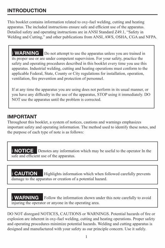
INTRODUCTION
This booklet contains information related to oxy-fuel welding, cutting and heating apparatus. The included instructions ensure safe and efficient use of the apparatus. Detailed safety and operating instructions are in ANSI Standard Z49.1, “Safety in Welding and Cutting,” and other publications from ANSI, AWS, OSHA, CGA and NFPA.
i WARNING Do not attempt to use the apparatus unless you are trained in its proper use or are under competent supervision. For your safety, practice the safety and operating procedures described in this booklet every time you use this apparatus. Industrial welding, cutting and heating operations must conform to the applicable Federal, State, County or City regulations for installation, operation, ventilation, fire prevention and protection of personnel.
If at any time the apparatus you are using does not perform in its usual manner, or you have any difficulty in the use of the apparatus, STOP using it immediately. DO NOT use the apparatus until the problem is corrected.
IMPORTANTThroughout this booklet, a system of notices, cautions and warnings emphasizes important safety and operating information. The method used to identify these notes, and the purpose of each type of note is as follows:
i NOTICE Denotes any information which may be useful to the operator In the safe and efficient use of the apparatus.
i CAUTION Highlights information which when followed carefully prevents damage to the apparatus or creation of a potential hazard.
i WARNING Follow the information shown under this note carefully to avoid injuring the operator or anyone in the operating area.
DO NOT disregard NOTICES, CAUTIONS or WARNINGS. Potential hazards of fire or explosion are inherent in oxy-fuel welding, cutting and heating operations. Proper safety and operating procedures minimize potential hazards. Welding and cutting apparatus is designed and manufactured with your safety as our principle concern. Use it safely.

2
SECTION 1: GENERAL SAFETY INFORMATION
The Work Area1. The work area must have fireproof floors; wall and work area. Check vicinity for any
flammable material and remove.2. Maintain adequate ventilation to prevent the concentration of oxygen/fuel gas,
flammable gases and/or toxic fumes. The presence of pure oxygen serves to accelerate combustion and causes materials to burn with great intensity. Oil and grease in the presence of oxygen can ignite and burn violently.
3. Work benches or tables must be secure and made of non-flammable material. 4. Chain or otherwise properly secure oxygen and fuel gas cylinders. Cylinders must be
stored according to all applicable fire codes and must be secured in upright position.5. Proper fire extinguishers as per NFPA codes must be accessible for emergency use.
Protective Apparel1. Protect yourself from sparks, flying slag, and flame brilliance at all times. Wear
goggles designed for Oxy-Fuel cutting or welding with tempered lenses shaded 4 or darker to protect eyes from injury and to provide good visibility of the work.
2. Wear protective gloves, sleeves, aprons and shoes to protect skin and clothing from sparks and slag. Keep all clothing and protective apparel absolutely free of oil or grease.
3. Never use oxygen to blow off dust or dirt off of protective clothing.
Fire PreventionPractice fire prevention techniques whenever oxy-fuel operations are in progress. A few simple precautions prevent most fires and minimize damage in the event a fire does occur. Always practice the following rules and safety procedures.1. Inspect oxy-fuel apparatus for oil, grease or damaged parts. DO NOT use the oxy
fuel apparatus if oil or grease is present or if damage is evident. Have the oxy-fuel apparatus cleaned and/or repaired by a qualified repair technician before using it.
2. Never use oil or grease on or around any oxy-fuel apparatus. Even a trace of oil or grease can ignite and bum violently in the presence of oxygen.
3. Keep flames, heat and sparks away from cylinders and hoses.4. Flying sparks can travel as much as 35 feet. Move combustibles a safe distance away
from areas where oxy-fuel operations are performed.5. Have a fire extinguisher of the proper type and size in the work area. Inspect it
regularly to ensure that it is proper working order. Know how to use it6. Follow all applicable NFPA regulations as it relates to fire prevention, gas storage
and fire extinguisher.7. When work is complete, inspect the area for possible fires or smoldering materials.

3
SECTION 2: INDUSTRIAL GASES
i CAUTION Contact your gas supplier for the appropriate Material Safety Data Sheet (MSDS) for each gas you use. The Hazardous Materials Regulations of the Department of Transportation (DOT) regulates the transportation of industrial gases and the cylinders used to transport them. Contact your cylinder supplier before safely disposing of any cylinders.
OxygenOxygen is an oxidizer and combined with a “fuel” gas produces the desired operating flame. The presence of pure oxygen will drastically increase the speed and force with which burning takes place. Oxygen can turn a small spark into a roaring flame or explosion
i WARNING Oil and/or grease in the presence of oxygen become highly Flammable or explosive. Never allow oxygen to contact oil, grease or other flammable substances.
Oxygen is stored in a variety of storage vessels in gas or liquid form. Oil, grease or all other contaminants in the presence of oxygen can auto-ignite. Serious injury may easily result if oxygen is used as a substitute for compressed air.
i WARNING NEVER USE OXYGEN:• In tools meant to run on air• To start internal combustion engines• To blow out pipelines• To dust off skin, clothing or work area• To create pressure in containers• For ventilationUse oxygen only in oxy-fuel welding, cutting and heating applications.
Oxygen CylindersHigh pressure oxygen cylinders are normally supplied in drawn or spun cylinders and are regulated by DOT for pressures and capacity. Capacities can run from 40 cu/ft to over 300 cu/ft. Oxygen is also stored in liquid form at low pressure for high volume demands. Ask your gas supplier for more safety and technical information.
Valve Outlet and Regulator Inlet ConnectionsCGA 540 up to 3000 PSIG CGA 577 up to 4000 PSIG CGA 701 up to 5500 PSIG

4
AcetyleneAcetylene is a compound of carbon and hydrogen (C2H2). It is a versatile industrial fuel gas used in cutting, heating, welding, brazing, soldering, flame hardening, metallizing, and stress relieving applications. Acetylene can become unstable when compressed in its gaseous state above 15 PSIG. Acetylene cylinders are completely filled with a porous material such as a lime-silica porous mass, filling is then saturated with liquid acetone. When acetylene is pumped into the cylinder, it is absorbed by the liquid acetone throughout the porous filling. It can now be pressurized up to 250 PSI and help in a stable condition. Acetylene cylinders can only be filled by qualified companies and must never be trans-filled.
Figure 1, Aceteylene Cylinder Interior
Acetylene CylindersAcetylene is available in a variety of capacities and sizes. Acetylene cylinders manufactured in the U.S. must conform to USDOT and Transport Canada specifications and regulations. Contact your fuel gas supplier for the specific properties of the fuel gas, if more detailed specifications are required. Cylinders have two safety plugs, one in the valve and another in the base of cylinder which melt at boiling temperature. This is to minimize the possibility of the cylinder exploding and allows the gas to vent in a controlled manner.

5
i WARNING Acetylene Storage:• When stored with oxygen must have a fire barrier separator be placed
an adequate distance away.• Cannot be stored or transported laid down• Store in well-ventilated area to prevent buildup of gases.• Check that valves are completely closed.
Specifications SafetyShock sensitivity ..................................................................Unstable over 15 PSIG outside
cylinderExplosive limits in oxygen,% .................................................................................... 3.0-93Explosive limits in air, % ........................................................................................... 2.5-80Maximum allowable use pressure ...........................................................................15 PSIG Tendency to backfire ....................................................................................... Considerable Toxicity ......................................................................................................................... Low Max. Withdrawal Rate ...................................................... l/7 of cylinder contents per hour
Combustion PropertiesNeutral flame temperature (CF) .....................................................................................5720Burning velocity in oxygen (ft./sec.) ..............................................................................22.7Primary flame (BTU/cu. ft.) ............................................................................................507Secondary flame (BTU /cu.ft.) ........................................................................................963Total heat (BTU/cu. ft.) .................................................................................................1470Total heating value (BTU/lb.) .................................................................................... 21,600Auto-ignition temperature (O F) ............................................................................ 763-824
Valve Outlet and Regulator Inlet ConnectionsStandard connection ............................................................................................... CGA 510Air Liquide Canada ................................................................................................ CGA 410Alternate standard connection ................................................................................ CGA 300Small valve series (10 cu. ft. cyl.) .......................................................................... CGA 200Small valve series (40 cu.ft.cyl.) ........................................................................... CGA 520All values are approximate.

6
i WARNING Acetylene gas can only be withdrawn at 1/7th of the cylinders volume. Exceeding that rate may pull acetone out the porous material and cause voids. If needing higher volumes either use a higher volume cylinder or manifold multiple cylinders together in an approved and safe manner. Discuss with your gas supplier your requirements before using.
MAPP® GasMAPP® gas, is a registered trademark of the Linde Group and is a mixture of liquefied petroleum gas (LPG) with high levels of propylene. True manufacturing of MAPP gas in the US ended in 2008.
Natural Gas and PropaneMethane is a colorless odorless and is the major component of natural gas about 75%. Mercaptan is used to add odor to the gases and can be smelled in small quantities. Both natural gas and propane are used as industrial fuel gases for flame cutting, scarfing, heating, flame hardening, stress relieving, brazing and soldering. Contact your fuel gas supplier for the specific properties of the fuel gas, if more detailed specifications are required.
Natural Gas and Propane CylindersNatural gas is transmitted by pipeline to most installations that use natural gas as a fuel gas. Propane is available in various size cylinders and on-site bulk storage tanks.
Safety Natural Gas PropaneShock sensitivity Stable StableExplosive limits in oxygen,%
5.0-59 2.4-57
Explosive limits in air,%
5.0-15 2.1-9.5
Maximum allowable use pressure
Determined by Equipment to be Used
Determined by Equipment to be Used
Tendency to backfire Slight Slight Toxicity Low Low

7
Combustion Properties
Natural Gas Propane
Neutral flame temperature (CF)
4600 4579
Burning velocity in oxygen (ft./sec.)
15.2 12.2
Primary flame (BTU /cu. ft.)
55 295
Secondary flame (BTU/cu. ft.)
995 2268
Total heat (BTU/cu. ft.) 1,050 2,563Total heating value (after vaporization) (BTU/lb.)
24,800 21,600
Auto-ignition temperature (CF)
999 874
All values are approximate.
Valve Outlet and Regulator Inlet ConnectionNatural Gas .........................................................................................................By PipelineMethane ................................................................................................................. CGA 350Methane .......................................................................................CGA 695 up to 5500 PSlG Propane .................................................................................................................. CGA 510
Propylene and Propylene Based Fuel GasesThese gases are hydrocarbon based products. They are industrial fuel gases used for flame cutting, scarfing, heating, flame hardening, stress relieving, brazing and soldering. They are used in certain applications for preheating large castings. Contact your gas supplier for the specific properties of the fuel gas, if more detailed specifications are required.
Gas CylindersThe fuel gas is available in on-site bulk storage tanks and portable cylinders. Cylinders are filled with liquid to a safe level and converts to a gas. Same as propane, flow in low outside temperatures will reduce gas withdrawal volumes
SPECIFICATIONSSafetyShock sensitivity StableExplosive limits in oxygen,% 2.0-57Explosive limits in air. % 2.0-10
8
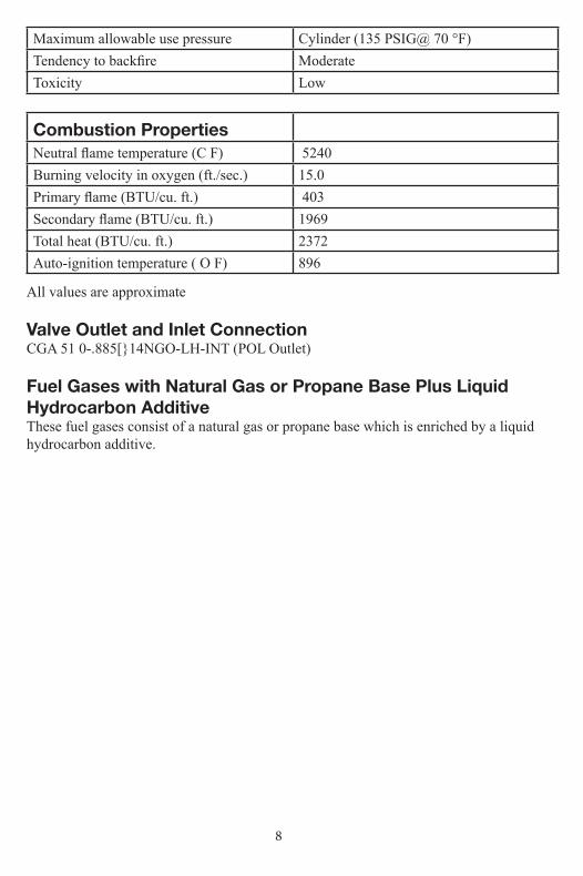
Maximum allowable use pressure Cylinder (135 PSIG@ 70 °F)Tendency to backfire Moderate Toxicity Low
Combustion PropertiesNeutral flame temperature (C F) 5240Burning velocity in oxygen (ft./sec.) 15.0Primary flame (BTU/cu. ft.) 403Secondary flame (BTU/cu. ft.) 1969Total heat (BTU/cu. ft.) 2372Auto-ignition temperature ( O F) 896
All values are approximate
Valve Outlet and Inlet ConnectionCGA 51 0-.885[}14NGO-LH-INT (POL Outlet)
Fuel Gases with Natural Gas or Propane Base Plus Liquid Hydrocarbon AdditiveThese fuel gases consist of a natural gas or propane base which is enriched by a liquid hydrocarbon additive.
9
SECTION 3: OXY-FUEL APPARATUS
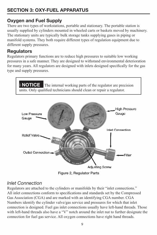
Oxygen and Fuel SupplyThere are two types of workstations, portable and stationary. The portable station is usually supplied by cylinders mounted in wheeled carts or baskets moved by machinery. The stationary units are typically bulk storage tanks supplying gases in piping or manifold systems. They both require different types of regulation equipment due to different supply pressures.
RegulatorsRegulators primary functions are to reduce high pressures to suitable low working pressures in a safe manner. They are designed to withstand environmental deterioration for many years. All regulators are designed with inlets designed specifically for the gas type and supply pressures.
i NOTICE The internal working parts of the regulator are precision units. Only qualified technicians should clean or repair a regulator.
Figure 2, Regulator Parts
Inlet ConnectionRegulators are attached to the cylinders or manifolds by their “inlet connections.”All inlet connections conform to specifications and standards set by the CompressedGas Association (CGA) and are marked with an identifying CGA number. CGANumbers identify the cylinder valve/gas service and pressures for which that inlet connection is designed. Fuel gas inlet connections usually have left-hand threads. Those with left-hand threads also have a “V” notch around the inlet nut to further designate the connection for fuel gas service. All oxygen connections have right hand threads.
10
i WARNING Always keep the regulator frees of oil, grease and other flammable substances. Never use oil or grease on the regulator, cylinder or manifold connection. DO NOT change the inlet connection on a regulator in an attempt to use the regulator for a different gas service.
Pressure Adjusting ScrewThe regulator adjusting screw controls the delivery pressure of the gas. Turning the adjusting screw clockwise allows gases to flow through the regulator to the hoses and to the torch. If the adjusting screw is turned fully counterclockwise, tension on the spring is released and the regulator does not allow the gas to flow.
Pressure GaugesThe high pressure gauge (closest to cylinder) indicates the cylinder or supply pressure entering the regulator. The low pressure gauge indicates the delivery pressure from the regulator to the hose. If you see damage to gauge face or needle, have checked out by a qualified technician.
Outlet ConnectionsWelding hoses are attached to the regulator outlet connections. Fuel gas regulatorsHave left-hand threaded outlet connections to mate with the left-hand hose connections and have a “V” notch around the outlet connection. Oxygen regulators have right-hand threaded outlet connections to Mate with the right-hand hose connections.
Relief Valve (where provided)The relief valve is designed to protect the low pressure side of the regulator from high pressures. Relief valves are not intended to protect downstream equipment from high pressures if seat fails Not installed on fuel gas regulators.
i WARNING DO NOT tamper with the relief valve or remove it from the regulator.
Gas HosesGas hoses allow low pressure gases (maximum 200 PSIG) from the regulators to the cutting or welding torch. Proper care and maintenance of the hose is critical so that dangerous gases do not leak through material or fittings.
Hose ConstructionIndustrial welding hose is usually color-coded for gas service identification.Oxygen hose is usually green and fuel hose is red. The hose walls are constructed

11
of continuous layers of rubber or neoprene material over a braided inner section. All approved domestically fabricated type VD grade “RM” and “T” hose are flameretardant. Grade “T” hose is recommended for all fuel gases and grade “RM is for acetylene only. The hose is marked to indicate its grade.
Hose CareWelding hoses are often exposed to severe abuse. The operator should frequently inspect the hoses and fittings for damage, when necessary, replace the hose.
Important Safety Notes• All fittings should be hand started and snug with correct sized wrench.• Keep welding hoses clear of any falling metal, slag or sparks.• Never allow hoses to become coated with oil, grease or dirt.• Examine the hoses before attaching to welding torch handle or regulators. If cuts,
burns, worn areas or damaged fittings are found, replace the hose.• Completely replace welding hose if it contains multiple splices or when cracks or
severe wear is noticed.• Check connections, leak (bubble) test with approved liquid.
Torch HandleA torch handle is a set of gas tubes and control valves. One tube and valve controls the fuel supply and the other tube and valve controls the oxygen supply. The torch handle is not designed to mix the gases for oxy-fuel processes.
The basic elements of a torch handle are listed as follows the control valves with internal reverse flow check valves, the “Y” body, barrel and tubes and the torch head. Check valves have a spring and disc, as long as there is positive pressure on the inlet side it will remain open. If pressure reverses spring will push disc into seat and shut gas flow.
Figure 3, Torch Handle Parts
12
Control Valves and Body “Y”The torch handle has two control valves installed in the “Y” body The valve bodies are marked; one valve has left-hand threads to accept the fuel gas hose. The other has right-had threads to accept the oxygen hose. The control valves never require lubricating. Packing nuts may require slight adjustment over time.
BarrelThe barrel and inner oxygen tube unit is designed to keep the oxygen and fuel Gases separated. A tube-within-a-tube design allows the oxygen supply to move through the inner tube to the head while the fuel supply travels through the interior tube.
Torch HeadThe torch head is threaded onto the barrel, creating a metal-to-metal seal. Tapered surfaces inside the head mate with O-rings when the cutting or welding attachment is connected creating a gas-tight seal. If damaged, the external threads and internal surfaces of the head may be reconditioned by a qualified technician. Never lubricate these surfaces.
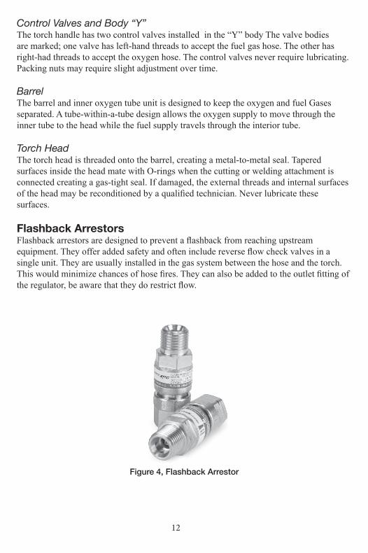
Flashback ArrestorsFlashback arrestors are designed to prevent a flashback from reaching upstream equipment. They offer added safety and often include reverse flow check valves in a single unit. They are usually installed in the gas system between the hose and the torch. This would minimize chances of hose fires. They can also be added to the outlet fitting of the regulator, be aware that they do restrict flow.
Figure 4, Flashback Arrestor

13
Cutting AttachmentThe cutting attachment functions as a convenient and economical approach toCutting operations where the frequency and/or application does not require a torch. Designed strictly for cutting. When connected to a torch handle, the cutting attachment functions as a cutting torch. It provides the operator with a wide range of cutting capabilities.
The basic elements of a cutting attachment are as follows: The cone end and coupling nut, the preheat oxygen control valve, the mixing chamber, the cutting oxygen lever and tube, and the cutting attachment head.
Figure 5, Cutting Attachment Parts
Cone End and Coupling NutThe cone end and coupling nut are designed to permit easy attachment to the torch handle. The tapered cone end is machined to mate with the torch handle head ,the o-rings also provide a hand-tight connection.
i WARNING There must always be two o-rings on the cone end. The absence or damage of either of these o-rings can lead to flashback within the torch handle or cutting attachment.
Preheat Oxygen Control ValveThe preheat oxygen control valve on the cutting attachment controls the preheat oxygen. Open the oxygen valve on the torch handle completely first. The preheat oxygen supply is then controlled by opening or closing the cutting attachment control valve. The fuel gas supply is controlled by the fuel valve on the torch handle.
14
Mixing Chamber TubeOxygen and fuel are fed into a mixing tube located in the bottom tube of the cutting attachment. Oxygen is directed to the mixer through the inner oxygen tube. The fuel gas is drawn from the exterior cavity of the attachment lower tube around the mixer. Mixed gases then flow through the preheat orifices of the cutting attachment head and in the preheat orifices of the cutting tip.
Cutting Oxygen Lever and TubeThe cutting oxygen lever is located above the body of the cutting attachment. Depressing the lever allows cutting oxygen to flow through the upper tube of the cutting attachment and the center port of the cutting attachment head.
Cutting Attachment HeadThe cutting attachment head allows the cutting oxygen and the mixed preheat gas to stay separated in the cutting operation. The internal taper of the head is stepped so the preheat gases can feed the cutting tip through the exterior orifices and the cutting oxygen can travel uninterrupted through the center port of the tip to the heated base metal. The exterior threads on the head allow a tip nut to compress a cutting tip into the tapered head. This creates a firm gas-tight metal-to-metal seat.
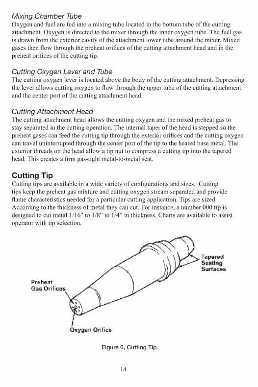
Cutting TipCutting tips are available in a wide variety of configurations and sizes. Cuttingtips keep the preheat gas mixture and cutting oxygen stream separated and provideflame characteristics needed for a particular cutting application. Tips are sizedAccording to the thickness of metal they can cut. For instance, a number 000 tip is designed to cut metal 1/16" to 1/8” to 1/4” in thickness. Charts are available to assist operator with tip selection.
Figure 6, Cutting Tip
15
i CAUTION Always make sure your equipment is rated for the size tip you have selected. A tip with too much capacity for the equipment can starve or choke the tip. This causes overheating of the head and a flashback may result. Use only genuine ATTC tips, welding nozzles and multi-flame nozzles to ensure leak-free connections and balanced equipment.
Tapered Seating SurfacesThe tapered end of the tip is machined to fit into the cutting attachment head. A tip nut secures the tip into the head. The tapered surfaces form a metal-to-metal seal (see Figure, page). Inspect both head and tip tapers frequently for signs of damage or wear.
Preheat Orifices and Oxygen OrificesMolten metal can splatter and stick to the cutting tip, clogging or obstructing the passages through which the gas must flow. Remove splatter from the tip orifices with small round files (tip cleaners). Repeated cleaning, however, can affect the flame shape and make the tip unsuitable for precise cutting.
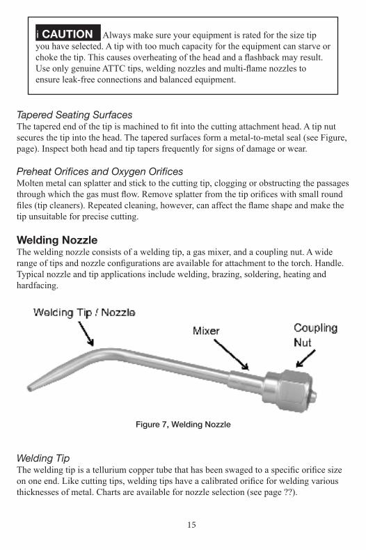
Welding NozzleThe welding nozzle consists of a welding tip, a gas mixer, and a coupling nut. A wide range of tips and nozzle configurations are available for attachment to the torch. Handle. Typical nozzle and tip applications include welding, brazing, soldering, heating and hardfacing.
Figure 7, Welding Nozzle
Welding TipThe welding tip is a tellurium copper tube that has been swaged to a specific orifice size on one end. Like cutting tips, welding tips have a calibrated orifice for welding various thicknesses of metal. Charts are available for nozzle selection (see page ??).

16
Gas MixerThe welding nozzle cone end is designed to mix the oxygen and fuel gases, whereas the cone end in the cutting attachment is not. When the oxygen meets with the fuel gas, a homogenizing mixing effect occurs resulting in a well-balanced flame shape. The welding nozzle has two O-rings and they maintain the separation of gases prior to the point at which mixing occurs. They allow a hand-tight connection of the welding tip and the torch handle.
i WARNING There must always be two o-rings on the cone end. The absence or damage of either of these o-rings allows premixing and leaks of oxygen and fuel gases. This can lead to flashback within the torch handle.
Coupling NutThe welding nozzle coupling nut is similar in design to the coupling nut on the cutting attachment.
Multi-Flame Heating NozzlesThe multi-flame heating nozzle is basically a large welding tip with multiple heating orifices. The cone end coupling nut and mixer assembly are similar in design to a welding tip. The multi-flame tip is machined to utilize numerous flames. They are available in various lengths due to reflected heat which could be intense.
i CAUTION Never starve or choke a multi-flame heating nozzle. This causes overheating of the head and a flashback may result. Should a flash-back occur or hear a load whistling noise, immediately turn off the oxygen valve on the torch handle, then, turn off the fuel valve. Allow the nozzle to cool before using again, if a flashback reoccurs, have the apparatus checked by a qualified technician before using again.
Basic Safety Recommendations• Check all equipment for damage and wear.• Use in an area that is free of flammables• All fittings are secure and routinely tested for leaks• All equipment is compatible for the gas type and pressures.• Have safety equipment nearby, such as fire blankets and fire extinguisher• Be familiar with equipment and gases, ask your gas supplier if unsure.• Wear appropriate clothing and safety equipment for the job.

17
SECTION 4: SETTING UP EQUIPMENT FOR WELDING
CylindersPlace the oxygen and fuel gas cylinders together where they are used. Secure themproperly (see Figure 8). Chain or secure cylinders to a cylinder cart, wall, work bench, post, in a safe area.
Figure 8, Securing the Cylinders
i CAUTION Cylinders are pressurized and flammable. Never allow cylinders to be dropped, knocked over or subjected to excessive heat. When stored or moving cylinders, cylinder caps should be secured on the cylinders
Important Safety Notes• Always keep cylinders secured properly in a vertical position.• Do not strike, drop or apply heat to any cylinder or valve.• Always keep valve protection caps in place whenever cylinders are moved or are in
storage (full or empty).• Separate empty cylinders from full cylinders.• Close valves completely on stored and empty cylinders.• Do not use a cylinder that does not have a gas identification label attached to it.• Do not use any cylinder with gouge marks or indents. Return to gas supplier
immediately.

18
Regulators1. Carefully inspect the cylinder valve and regulator threads and mating surfaces for
traces of oil or grease. Make sure the regulator has the correct pressure rating for the cylinder being used (see Figure 9).
Figure 9, Inspecting the Cylinder and Cylinder Valve
Figure 10, Cracking the Cylinder Valve
19
i WARNING DO NOT use the regulator if oil, grease or damaged parts are detected on the regulator or the cylinder valve or if the inlet filter is missing or dirty. Inform your gas supplier of this condition immediately. Have a qualified repair technician clean or repair the regulator.
2. Momentarily slightly open and close (called “cracking”) the cylinder valve in a well-ventilated area. This dislodges any loose contaminant within the valve. (see Figure 9, page 18). Open the cylinder valve only slightly When “cracking” the cylinder valve, DO NOT stand directly in front of the valve. Stand to one side cylinder between you and the valve (see Figure 10, page 18).
3. An acetylene cylinder may spray a mist when it is cracked, let it set for 15 minutes. Then try to crack the cylinder valve again. If the problem persists, contact your gas supplier.
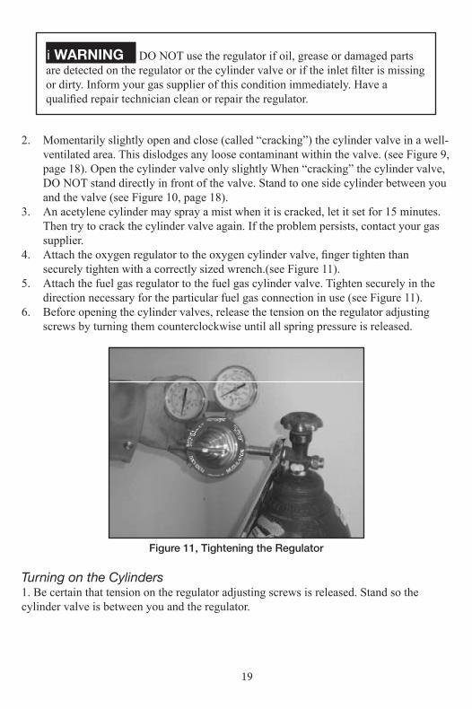
4. Attach the oxygen regulator to the oxygen cylinder valve, finger tighten than securely tighten with a correctly sized wrench.(see Figure 11).
5. Attach the fuel gas regulator to the fuel gas cylinder valve. Tighten securely in the direction necessary for the particular fuel gas connection in use (see Figure 11).
6. Before opening the cylinder valves, release the tension on the regulator adjusting screws by turning them counterclockwise until all spring pressure is released.
Figure 11, Tightening the Regulator
Turning on the Cylinders1. Be certain that tension on the regulator adjusting screws is released. Stand so the cylinder valve is between you and the regulator.

20
i WARNING Never stand in front or behind a regulator when opening the cylinder valve. Always stand so that the cylinder is between you and the regulator.
Slowly and carefully open the oxygen cylinder valve until the maximum pressure registers on the high pressure gauge. Now, open the oxygen cylinder valve completely to seal the valve packing (see Figure 12).
Figure 12, Opening the Cylinder Valve
7. Slowly open the fuel gas cylinder valve in the same manner.
i NOTICE DO NOT open acetylene cylinder valves more than 1 1/2 turns and, preferably, no more than 3/4 turn. Keep the cylinder wrench, if one is required, on the cylinder valve so the cylinder may be turned off quickly, if necessary.
We strongly recommend using reverse flow check valves on the torch handle to reduce the possibility of mixing gasses in the hoses and regulators. Mixed gases can explode in the hoses, regulators or cylinders, resulting in serious damage to the equipment or injury to the operator.

21
Figure 13, Torch mount check valves and flashback arrestors included.Regulator check valves and arrestors optional.
Important Safety Notes• Be certain cylinder valves and regulator connections are completely free of dirt, dust,
oil or grease.• Inspect valves for grease oil, grease or damage if detected DO NOT use. Notify
cylinder supplier immediately.• Inspect regulators for oil, grease or damage and if detected DO NOT use. Have it
cleaned or repaired by a qualified repair technician.• Never stand directly in front or behind a regulator when opening the cylinder valve.
Stand so the cylinder valve is between you and the regulator.• Always open cylinder valves slowly and carefully.• Always check for leaks on the regulator and cylinder valve connections using
appropriate test liquids.
Welding Hoses1. Connect the oxygen hose to the oxygen regulator finger tight, tighten firmly with the
appropriate wrench. 2. Adjust the oxygen regulator to allow 3 to 5 PSIG to escape through the hose. Allow
oxygen to flow 5 to 10 seconds to clear the hose of dust, dirt, or preservative. Then, shut off the oxygen flow. Attach and clear the fuel hose in the same manner.

22
Figure 14, Connecting the Hose
i WARNING Be sure to clear hoses in a well-ventilated area! The escaping gases create conditions for fires and explosions!
Torch Handle1. Inspect the torch handle head, valves and hose connections for oil , grease or
damaged parts. DO NOT use if oil, grease or damage is detected.2. Inspect the torch head. The tapered seating surfaces must be in good condition. If
dents, bums or burned seats are present, the seat must be resurfaced. If the torch is used with poor seating surfaces, backfire or flashback may occur.
3. We strongly recommend the use of check valves on any torch handle to reduce the possibility of mixing gases in the hoses and regulators. If accessory check valves are required, connect them to the proper control valve.
4. Attach the welding hose to the torch handle or reverse flow check valves tighten securely. (See figure 15)

23
Figure 15, Connecting accessory check valve/flashback arrestor and hose to torch handle.
Welding Nozzle1. Inspect the cone end, coupling nut, o-rings and welding nozzle for damage, oil or grease.
i WARNING There must always be two o-rings on the cone end. The absence or damage of either of these o-rings allows premixing and leaks of oxygen and fuel gases. This can lead to flashback within the torch handle.
2. Connect the welding nozzle to the torch handle. Tighten the coupling nut hand-tight only. Wrench tightening may damage o-rings and create a faulty seal (see Figure 16).
Figure 16, Connecting the Welding Nozzle to Torch Handle
24
Multi-Flame Heating NozzlesMulti-flame heating nozzles are set up exactly as the welding tip or nozzle. Follow the safety and operation procedures described below for the welding nozzle.
i WARNING Never starve or choke a multi-flame heating nozzle. This will cause overheating of the head and a flashback may result. Should a flash-back occur (flame disappears and/or a whistling sound when the flame burns inside the nozzle), immediately turn off the oxygen valve on the torch handle. Then, turn off the fuel valve. Allow the nozzle to cool before attempting to reuse. If a flashback or burnback reoccurs, have the apparatus checked by a qualified repair technician before using again.
Leak-Testing the SystemThe system MUST be tested for leaks before lighting the torch . Leak test the system by performing the following steps:
High Pressure Test1. With the oxygen cylinder valve open, adjust the oxygen regulator to deliver 20 PSIG.2. With the fuel cylinder valve open, adjust the fuel regulator to deliver 5 PSIG.3. Be sure that both the oxygen and fuel control valves on the torch handle are closed.4. Close both the oxygen and fuel cylinder valves.5. Turn the adjusting screws counterclockwise and relieve spring pressure.6. Observe the gauges on both regulators for if the gauge readings do not change, then
the system is leak tight. If there is a leak, use approved leak detection liquid to detect it.
7. If the H.P. Gauge reading decreases, there is a leak at the cylinder valve or inlet connection. Tighten the inlet connection after the pressure has been released from the regulator.
8. If the inlet connection still leaks, take the regulator to a qualified repair technician. Never tighten a cylinder valve. If the cylinder valve is leaking, remove the regulator from the cylinder, place the cylinder outdoors. Notify your gas supplier immediately.
Low Pressure Test1. Make sure all torch valves are closed2. Pressurize system as above3. Close cylinder valves4. If the L.P. gauge reading decreases, there is a leak between the regulator outlet
connection and control valves on the torch handle. 5. Test all connections with approved liquids and check hose for cracks. If these
connections are still leaking, take the regulator or torch handle to a qualified repair technician. If the hoses are leaking, replace them.
6. After leak testing the system, open the cylinder valves and proceed.

25
i NOTICE : There are many types of liquid solutions used for leak testing, product has to be compatible with oxygen. CGA does not recommend using standard soaps and water.
Setting Up to Weld, Lighting the Torch and Adjusting the Flame
i WARNING Perform all welding in a well ventilated area to help prevent the concentration of flammable and/or toxic fumes.
1. Refer to welding tip selection charts to determine the tip size required and regulator pressures for the job (see page 43).
2. Open the oxygen valve on the torch handle. Adjust the oxygen regulator to the desired delivery range (see Figure 17).
3. Close the torch handle oxygen valve. Open the fuel valve on the torch handle. Adjust the fuel regulator to the required delivery range.
4. Close the torch fuel control valve.
Figure 17, Setting Operating Pressures
5. Open the fuel valve on the torch handle. Adjust the fuel regulator to the required delivery range.6. Close the torch fuel control valve.

26
i WARNING If the torch handle and hoses are already connected to the regulators, the system MUST still be purged after every shut-down. Open the oxygen valve 11/2 turn. Allow the gas to flow ten seconds for tips up to size 3 and 5 seconds for sizes 4 and larger for each 25 feet of hose in the system. Close the oxygen valve. Purge the fuel system in the same manner.
7. Wear protective goggles to shield eyes from bright light and protective clothing as required.
i NOTICE The following instructions cover torch adjustment procedures for acetylene only. Contact your gas supplier for instructions on use of other fuel gases.
Figure 18, Lighting the Torch
8. Hold the torch in one hand and the spark lighter in the other (see Figure 17). Be sure the spark lighter is away from the tip and not obstructing the gas flow.9. Open the torch fuel valve approximately 1/8 turn. Ignite the gas.
i CAUTION Point the flame away from people, equipment, and any flammable materials.

27
Figure 19, Lighting the Torch
10. Continue opening the fuel valve until the flame stops smoking (see Figure 16).11. Open the torch oxygen valve until a bright neutral flame is established (see Figure 20).
i NOTICE If the flame produces too much heat for the work tip, DO NOT decrease the pressures or close the valves. Use a smaller tip.
Figure 20, Acetylene Welding Flames
28
i WARNING If you experience a backfire or flashback (a shrill hissing sound when the flame is burning inside the welding nozzle), immediately turn off the oxygen valve. Then, turn off the fuel valve. Allow the torch and nozzle to cool before attempting to reuse. If backfire and flashback reoccurs, bring the apparatus to a qualified repair technician for repair before using again.
When You Finish You Welding Operation1. Shut off the torch oxygen valve. Then, shut off the torch fuel valve. If this procedure
is reversed, a “pop” may occur, The “pop” throws carbon soot back into the torch and may in time partially clog gas passages.
2. Close both cylinder valves.3. Open the torch handle oxygen valve. Let the oxygen in the system drain out. Close
the torch oxygen valve.4. Turn the adjusting screw on the oxygen regulator counterclockwise to release all
spring pressure.5. Open the torch handle fuel valve. Release the pressure in the system. Close the torch
fuel valve.6. Turn the adjusting screw on the fuel gas regulator counterclockwise to release all
spring pressure.7. Check the H.P gauges after a few minutes to be sure the cylinder valves are turned
off completely.
SECTION 5: WELDING PROCEDURES
In oxy-fuel welding, two metals are joined by melting or fusing their adjoining surfaces. This is accomplished by directing an oxy-fuel flame over the metals until a molten puddle is formed. A filler rod may be introduced into the puddle to help the metals form together.
Preparing the Metals to be Welded1. Clean the metal joints to be welded of all scale, rust, dirt, paint and grease. Any foreign material in the molten puddle changes the metal composition and weakens it.

29
Figure 21, Preparing the Metal
2. Base metals 1/8" or less do not require beveling. Thicker metals require additional preparation (see Figure 21).3. Place the metal to be welded on the work table. Determine if and where tacking may be required.
i NOTICE As a welding bead is applied, the two pieces of metal may tend to pull together, closing the penetration gap.
To prevent warping1. Fuse the ends of the two pieces of metal together before welding. Long pieces may
need to be fused every few inches or so along the joint (see Figure 21).2. Long pieces may require additional penetration gap. Add 1/8" to 1/4" per linear foot.
Forehand and Backhand Welding TechniquesTwo techniques are employed for oxy-fuel welding; forehand and backhandwelding (see Figure 21). The forehand technique is recommended for welding material up to 1/8" thickness because of better control of the small weld puddle. Backhand welding is, generally, more suitable for material 1/8" and thicker. Increased speed and better fusion at the root of the weld is normally achieved with backhand welding.
30
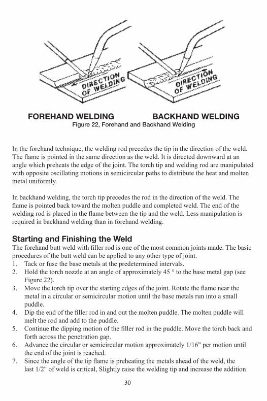
FOREHAND WELDING BACKHAND WELDINGFigure 22, Forehand and Backhand Welding
In the forehand technique, the welding rod precedes the tip in the direction of the weld. The flame is pointed in the same direction as the weld. It is directed downward at an angle which preheats the edge of the joint. The torch tip and welding rod are manipulated with opposite oscillating motions in semicircular paths to distribute the heat and molten metal uniformly.
In backhand welding, the torch tip precedes the rod in the direction of the weld. The flame is pointed back toward the molten puddle and completed weld. The end of the welding rod is placed in the flame between the tip and the weld. Less manipulation is required in backhand welding than in forehand welding.
Starting and Finishing the WeldThe forehand butt weld with filler rod is one of the most common joints made. The basic procedures of the butt weld can be applied to any other type of joint.1. Tack or fuse the base metals at the predetermined intervals.2. Hold the torch nozzle at an angle of approximately 45 ° to the base metal gap (see
Figure 22).3. Move the torch tip over the starting edges of the joint. Rotate the flame near the
metal in a circular or semicircular motion until the base metals run into a small puddle.
4. Dip the end of the filler rod in and out the molten puddle. The molten puddle will melt the rod and add to the puddle.
5. Continue the dipping motion of the filler rod in the puddle. Move the torch back and forth across the penetration gap.
6. Advance the circular or semicircular motion approximately 1/16" per motion until the end of the joint is reached.
7. Since the angle of the tip flame is preheating the metals ahead of the weld, the last 1/2" of weld is critical, Slightly raise the welding tip and increase the addition

31
of filler rod to ensure a full smooth weld . Refer to Figure 23, page 31 for visual characteristics of good and bad weld joints.
Figure 23, Starting and Finishing the Weld
"
" "
"
"

32
When You Finish You Welding Operation1. Shut off the torch oxygen valve. Then, shut off the torch fuel valve. If this procedure
is reversed, a “pop” may occur, The “pop” throws carbon soot back into the torch and may in time partially clog gas passages.
2. Close both cylinder valves.3. Open the torch handle oxygen valve. Let the oxygen in the system drain out. Close
the torch oxygen valve.4. Turn the adjusting screw on the oxygen regulator counterclockwise to release all
spring pressure.5. Open the torch handle fuel valve. Release the pressure in the system. Close the torch
fuel valve.6. Turn the adjusting screw on the fuel gas regulator counterclockwise to release all
spring pressure.7. Check the H.P gauges after a few minutes to be sure the cylinder valves are turned
off completely.
Figure 24, Characteristics of Good and Bad Welding Joints
33
Oxy-Fuel Brazing and Braze WeldingBrazing is a form of welding characterized by heating the base metal to temperatures above 700° F, but below its melting point. Most metals can be joined by brazing. However, the proper filler rod and flux must be used. Contact your local supplier for charts on the various filler rods and fluxes that are available. Flux is required to prepare the metals for joining. The filler rod bonds the base metals together.
Preparing the Metals to be BrazedThe successful brazing operation depends on close joint tolerances. Usually theclearance is beween 0.001 and 0.010 inch. Clean away paint, rust, grease and dirt prior to beginning the brazing operation. After cleaning the parts, assemble or secure the joints for brazing at the welding station.
i CAUTION Perform all brazing processes in a well-ventilated area. Toxic fumes may be generated by the brazing process. Refer to the Material Safety Data Sheet (MSDS) for the brazing rod.
Setting Up for Brazing Applications1. Refer to the Welding Nozzle Data Charts (page 42) to select the proper welding
nozzle size and regulator pressure settings.2. Follow safety and operating procedures for setting up welding and heating nozzles.3. Follow safety and operating procedures for setting up cylinders and regulators.
Brazing Sheet SteelThe brazing procedures described apply to brazing strips of sheet steel. The techniques can be utilized in all brazing applications.1. Heat the tip of the brazing rod and dip into the flux. Some flux will adhere to the
heated rod.
i NOTICE Some rods already have a flux coating.
2. Preheat metal only to a dull red color. If the base metal is heated to a higher temperature, a porous deposit will result.
3. Touch the fluxed rod to the heated metal. Allow some flux to melt and react with the base metal. The melted flux reacts to chemically clean the base metal.
4. Melt off small amounts of fluxed rod as you braze. If the rod flows freely and “tins” (adheres to the heated base metal), you have reached the correct temperature. Maintain this temperature by continually moving the flame over the metal.
5. Continue to tip the rod into the flux. Add sufficient rod to the base metal to build up the bead.
6. Continue to tin and build a bead until the desired section is covered.

34
When You Finish Your Brazing OperationFollow the same procedures as for shutting down the welding operation.
SECTION 6: SETTING UP EQUIPMENT FOR CUTTINGThe oxy-fuel cutting process consists of preheating the base metal to a bright cherry red. Then, a stream of cutting oxygen is introduced. This ignites and bums the metal, carrying away the slag or oxidized residue. Oxy-fuel cutting can be applied to plain carbon steels, low-alloy steels and some other ferrous metals. Nonferrous metals, stainless steels and cast iron are not usually cut using oxy-fuel equipment.
Setting Up for Cutting Applications1. Inspect the cone end, coupling nut, and torch head for oil, grease, or damaged parts.
Inspect the cone end for missing or damaged o-rings.
i WARNING If you find oil, grease or damage, DO NOT use the apparatus until it has been cleaned and/or repaired by a qualified repair technician. There must be two o-rings in good condition on the cone end. The absence of either of these o-rings allows pre-mixing of oxygen and fuel gases. This can lead to flashback within the cutting attachment.
2. Inspect the cutting tip and cutting attachment head. All tapered seating surfaces must be in good condition. Discard damaged cutting tips. If you find dents, burns or burned seats, resurface the torch head. If you use the cutting attachment with poor seating surfaces, backfire or flashback may occur.
i WARNING These seating surfaces prevent premature mixing of gases that can cause fires and explosions. If the rapered seats on the tip are damaged, DO NOT use it!
3. Inspect the preheat and cutting oxygen holes on the tip. Splatter can stick on or in these holes. If the holes are clogged or obstructed, clean them out with the proper size tip cleaner.
35
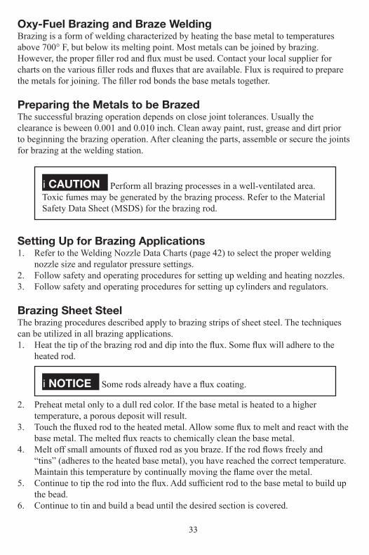
Figure 25, Connecting Cutting Attachment to Torch Handle
Figure 26, Tightening the Tip Nut
4. Insert tip in the cutting attachment head. Tighten the tip nut securely with a wrench (15 to 20 lbs. torque. See Figure 25).
5. Connect the cutting attachment to the torch handle and tighten the coupling nut, hand-tight only. Wrench tightening may damage a-rings, creating a faulty seal.
6. Refer to the Tip Flow Data Charts for correct cutting tip, regulator pressures, and travel speed (see page 42).
7. Follow cylinder and regulator safety and operating procedures.8. Open the oxygen valve on the torch handle completely.9. Open the preheat oxygen control valve on the cutting attachment. Adjust the oxygen
regulator to the desired delivery pressure.10. Close the preheat oxygen control valve11. Open the fuel valve on the torch handle. Adjust the fuel regulator delivery range.12. Close the fuel control valve on the torch handle.13. Momentarily, depress the cutting oxygen lever to purge the cutting oxygen passage.

36
i WARNING If the torch handle and hoses are already connected to the regulators, the system MUST still be purged after every shut-down. Open the oxygen valve 112 turn. Allow the gas to flow ten seconds for tips up to size 3 and 5 seconds for sizes 4 and larger for each 25 feet of hose in the system. Close the oxygen valve. Purge the fuel system in the same manner.
14. Open the fuel valve on the torch handle approximately 1/8 tum. Ignite the gas with a spark lighter. Be sure the spark lighter is away from the tip and not obstructing the gas flow.
i NOTICE Wear protective clothing. Use goggles to shield the eyes from bright light.
15. Continue to increase the fuel supply at the torch handle until the flame stops smoking.
16. Slowly open the preheat oxygen control valve on the cutting attachment until the preheat flames establish a sharp inner cone. The configuration of the short inner cone is called the Neutral Flame.
17. Depress the cutting oxygen lever. If the preheat flame changes slightly to a carburizing flame, continue to depress the cutting oxygen lever. Increase the preheat oxygen at the cutting attachment until the preheat flames are again neutral. If the preheat flames are not the same size and the cutting oxygen on straight, tum off the torch. Let it cool. Clean the tip.
i WARNING If you experience a backfire or flashback (flame disappears and/or a shrill hissing sound when the flame is burning inside the cutting at tachment) immediately turn off the preheat oxygen control valve on the cutting attachment. Then, turn off the torch handle fuel valve. Allow the cutting attachment to cool before attempting to relight. If backfire and flashback re occurs, have the apparatus checked by a qualified repair technician before using again.
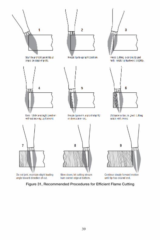
IMPORTANTInspect the areas where molten metal and sparks will fall. Serious fires and explosions are caused by careless torch operations. Take all possible precautions. Have fire extinguishers available. Remove or protect flammable substances, including oxy gen and fuel hoses, before starting to work. Refer to Figure 30, page 37 for a graphic sequence of recommended procedures for efficient flame cutting.

37
18. Hold the cutting attachment or torch handle comfortably in both hands. Stabilize the torch with one hand . Position the cutting tip preheat flames approximately 1/8” from the base metal. The other hand is free to depress the cutting oxygen lever.
19. Direct the preheat flame to the spot where you want to start the cut (see Figure 26 Before the cutting action can start, preheat the base metal to a bright cherry red When the red spot appears, depress the cutting oxygen lever slowly and fully.
Figure 27, Starting the Cut
20. When the cut starts, move the torch in the direction you wish to cut (see figure 27).
i NOTICE Moving too slowly allows the cut to fuse together. Moving too fast will not preheat the metal and the cut will be lost.
Figure 28, Cutting
21. Continue to depress the cutting oxygen lever past the final edge of the base metal for a good drop cut (see Figure 31, page 39).

38
Starting a Cut by Piercing1. Preheat a small spot on the base to a bright cherry red (see Figure 29).
Figure 29, Starting to Pierce
2. Tilt the torch tip slightly to one side. This prevents the sparks and slag from blowing toward you.
3. When the metal is pierced, straighten the torch. Move the torch steadily in the direction you wish to cut (see Figure 30).
Figure 30, Piercing
39
Figure 31, Recommended Procedures for Efficient Flame Cutting

40
i NOTICE If the metal is not pierced all the way through, it probably means that you are not using enough cutting oxygen pressure.
Figure 32, Cutting by Piercing
When You Finish Your Cutting Operation1. Close the oxygen preheat valve. Then, close the torch fuel valve. If this procedure is
reversed, a pop may occur. The pop throws carbon soot back into the torch and may, in time, partially clog gas passages.
2. Close both cylinder valves. 3. Open the preheat oxygen valve and/or depress the cutting oxygen lever. Release the
pressure in the system. Close the preheat oxygen valve and the torch handle oxygen valve.
4. Turn the adjusting screw on the oxygen regulator counterclockwise to release all spring pressure.
5. Open the torch handle fuel valve. Release the pressure in the system. Close the fuel valve
6. Turn the adjusting screw on the fuel gas regulator counterclockwise to release all spring pressure.
7. Check the H.P. gauges after a few minutes to be sure the cylinder valves are shut off completely.
8. Remove slag left on the cut edge with a chipping hammer or brush. Never remove slag from the cut edge with the torch head or cutting tip.

41

42
43
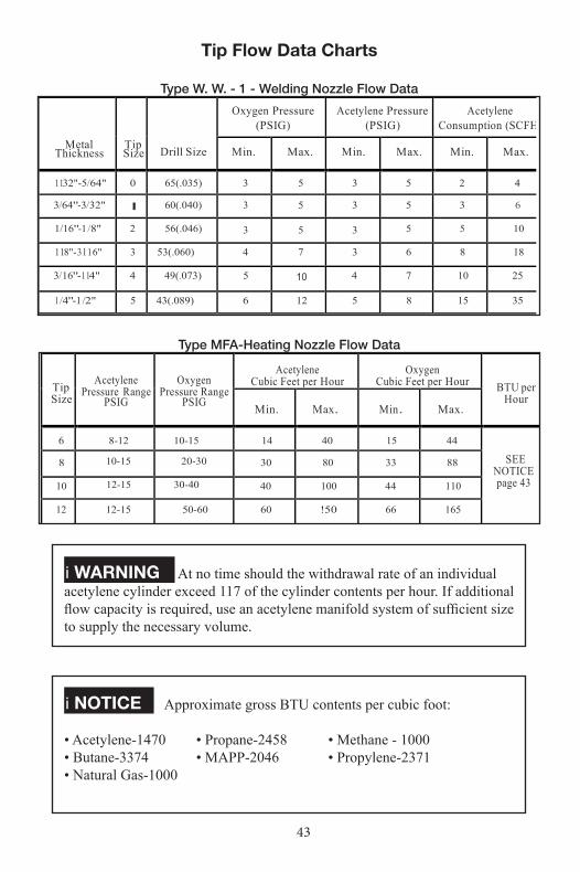
Tip Flow Data Charts
Type W. W. - 1 - Welding Nozzle Flow Data
Metal Thickness
Tip Size
Drill Size
Oxygen Pressure (PSIG)
Acetylene Pressure (PSIG)
Acetylene Consumption (SCFH)
Min.
Max.
Min.
Max.
Min.
Max.
1132"-5/64" 0 65(.035) 3 5 3 5 2 4
3/64"-3/32" I 60(.040) 3 5 3 5 3 6
1/16"-1 /8" 2 56(.046) 3 5 3 5 5 10
118"-3116" 3 53(.060) 4 7 3 6 8 18
3/16"-114" 4 49(.073) 5 10 4 7 10 25
1 /4"-1 /2" 5 43(.089) 6 12 5 8 15 35
Type MFA-Heating Nozzle Flow Data
Tip Size
Acetylene
Pressure Range PSIG
Oxygen
Pressure Range PSIG
Acetylene Cubic Feet per Hour
Oxygen Cubic Feet per Hour
BTU per Hour
Min.
Max.
Min.
Max.
6 8-12 10-15 14 40 15 44
SEE NOTICE page 43
8 10-15 20-30
30
80
33
88
10 12-15 30-40 40 100 44 110
12 12-15 50-60 60 !50 66 165
i WARNING At no time should the withdrawal rate of an individual acetylene cylinder exceed 117 of the cylinder contents per hour. If additional flow capacity is required, use an acetylene manifold system of sufficient size to supply the necessary volume.
i NOTICE Approximate gross BTU contents per cubic foot:
• Acetylene-1470 • Propane-2458 • Methane - 1000• Butane-3374 • MAPP-2046 • Propylene-2371• Natural Gas-1000
44
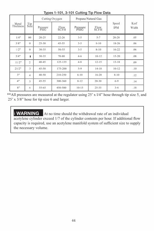
Types 1-101, 3-101 Cutting Tip Flow Data
Metal Thickness
Tip Size
Cutting Oxygen
Propane/Natural Gas
Speed IPM
Kerf Width
Pressure
PSIG
Flow SCFH
Pressure
PSIG
Flow SCFH
1/4" 00 20-25 22-26 3-5 5-7 20-28 .05
3/8" 0 25-30 45-55 3-5 8-10 18-26 .06
1 /2" 0 30-35 50-55 3-5 8-10 16-22 .06
3/4" I 30-35 70-80 4-6 10-12 15-20 .08
11 /2" 2 40-45 125-135 4-8 12-15 13-18 .09
21/2" 3 45-50 175-200 5-9 14-18 10-12 .10
3" 4 40-50 210-250 6-10 16-20 8-10 .12
4" 5 45-55 300-360 8-12 20-30 6-9 .14
8" 6 55-65 450-500 10-15 25-35 3-4 .18
**All pressures are measured at the regulator using 25’ x l/4” hose through tip size 5, and 25’ x 3/8” hose for tip size 6 and larger.
i WARNING At no time should the withdrawal rate of an individual acetylene cylinder exceed 1/7 of the cylinder contents per hour. If additional flow capacity is required, use an acetylene manifold system of sufficient size to supply the necessary volume.

45
Type GPN-Propane/Natural Gas Tip Flow Data
Metal Thickness
Tip Size
Cutting Oxygen
Propane/Natural Gas
Speed IPM
Kerf Width
Pressure
PSIG
Flow SCFH
Pressure
PSIG
Flow SCFH
1/4" 00 20-25 22-26 3-5 5-7 20-28 .05
3/8" 0 25-30 45-55 3-5 8-10 18-26 .06
1 /2" 0 30-35 50-55 3-5 8-10 16-22 .06
3/4" I 30-35 70-80 4-6 10-12 15-20 .08
11 /2" 2 40-45 125-135 4-8 12-15 13-18 .09
21/2" 3 45-50 175-200 5-9 14-18 10-12 .10
3" 4 40-50 210-250 6-10 16-20 8-10 .12
4" 5 45-55 300-360 8-12 20-30 6-9 .14
8" 6 55-65 450-500 10-15 25-35 3-4 .18
i WARNING High gas withdrawal rates require use of a manifold system of sufficient size to supply the necessary volume.

46
GLOSSARY
This section explains the meaning of terms most used by welders. Technical engineering terms have been simplified.
AACETYLENE - Gas composed of two parts of carbon and two parts of hydrogen. When burned in the atmosphere of oxygen, it produces one of the highest flame temperatures obtainable.
ACETYLENE CYLINDER - (See GasCylinder)
ACETYLENE HOSE - (See Hose)
ACETYLENE REGULATOR - Manually adjustable device used to reduce cylinder pressure to torch pressure and to keep the pressure constant. They are never to be used as oxygen regulators.
ANSI - Abbreviation for American National Standard Institute.
AWS - Abbreviation for American Welding Society.
BBRAZE WELDING - A welding process variation in which a filler metal, having a liquidus above 840° F (450° C) and below the solidus of the base metal is used. Un-like brazing, in braze welding the filler metal is not distributed in the joint by capillary action.
BUILDUP - A surfacing variation in which surfacing metal is deposited to achieve the required dimensions.
BURNING - A nonstandard term for OXYGEN CUTTING.
CCARBON - An element which when
combined with iron, forms various kinds of steel. In steel, it is the changing carbon content which changes the physical properties of the steel. Carbon is also used in a solid form as an electrode for arc welding and as a mold to hold metal.
CARBONIZING FLAME - A nonstan-dard term for REDUCING FLAME.
CARBURIZING FLAME- A nonstan dard term for REDUCING FLAME.
CASEHARDENING- Adding of carbon to the surface of a mild steel object and heat treating to produce a hard surface.
CASTINGS - Metallic forms that are pro duced by pouring molten metal into a shaped container (mold).
CGA -Abbreviation for Compressed GasAssociation.
CONCAVE FILLET WELD - A weld having a concave face.
CONE - The conical part of an oxy-fuel flame next to the orifice of the tip.
CONTINUOUS WELD - A weld that extends continuously from one end of the joint to the other. Where the joint is essentially circular, it extends completely around the joint.
CRACKING - Action of opening a valve slightly and then closing the valve immediately.
CUTTING TORCH - A device used in gas cutting.
CYLINDER - (See Gas Cylinder)
DDOT - Abbreviation for Department ofTransportation.
FFILTER LENS - A round or rectangular

47
shaded filter plate. Usually shade 4 – 6 for Oxy-Fuel welding and cutting
FLAME CUTTING - A nonstandard term for cutting with Oxy-Fuel.
FUSION - The melting together of filler metal and bade metals.
GGAS CYLINDER - A portable container used for transportation and storage of a compressed gas.
HHOSE - Flexible medium used to carry gases from regulator to the torch. It is made of fabric and rubber or neoprene.
HYDROGEN - A gas formed of the single element hydrogen. It is considered one of the most active gases. When combined with oxygen, it forms a very clean flame.
JJOINT - The junction of members or the edges of members which are to be joined or have been joined.
JOINT PENETRATION - The depth a weld extends from its face into a joint, exclusive of reinforcement.
LLENS- Consists of clear protective lens and filter lens (See Filter Lens)
MMIXING CHAMBER - That part the welding torch or cutting torch in which the fuel gas and oxygen are mixed.
NNEUTRAL FLAME- An oxy-fuel gas flame in which the portion used is neither oxidizing nor reducing.
NFPA - Abbreviation for National Fire
Protection Association.
NOZZLE- (See Tip)
OORIFICE - Opening through which gas flows. It is usually the final opening con trolled by a valve.
OSHA - Abbreviation of OccupationalSafety and Health Administration.
OUTSIDE CORNER WELD - Fusing two pieces of metal together with the fusion taking place on the underpart of the seam.
OXIDIZING - Combining oxygen with any other substance. For example, a metal is oxidized when the metal or parts of it are burned or exposed to oxygen.
OXIDIZING FLAME - An oxy-fuel gas flame having an oxidizing effect due to excess oxygen.
OXY-ACETYLENE CUTTING - An oxy-fuel gas cutting process used to sever metals by means of the reaction of oxygen with the base metal as elevated temperatures. The necessary temperature is main tained by gas flames resulting from the combustion of acetylene with oxygen.
OXY-ACETYLENE WELDING - An oxy-fuel gas welding process that produces fused metals by heating them with a gas flame or flames obtained from the combustion of acetylene with oxygen. The process may be used with or without the application of pressure and with or without the use of a filler metal.
OXYGEN - A gas formed of element oxygen. When oxygen very actively sup ports combustion it is called burning; when oxygen is slowly combined with a substance it is called oxidation.
OXYGEN CUTTING - Cutting metal
48
using the oxygen jet which is added to an oxygen-acetylene flame.
OXYGEN CYLINDER - (See Gas Cylinder)
OXYGEN HYDROGEN FLAME - The chemical combining of oxygen with the fuel gas hydrogen.
OXYGEN HOSE- (See Hose)
OXYGEN L.P. GAS FLAME - Chemi cal combining of oxygen with the fuel gas L.P. (liquefied petroleum).
OXYGEN REGULATOR - Manually adjustable device used to reduce cylinder pressure to torch pressure and to keep the pressure constant. They are never to be used as fuel gas regulators.
POROSITY - Cavity type discontinuities formed by gas entrapment during solidification.
POSTHEATING - The application of heat to an assembly after welding, cutting or heating.
POSTHEATING - Coating the base metal in the joint prior to soldering or brazing.
PREHEATING - The application of heat to the base metal immediately before welding or cutting.
PUDDLE - A nonstandard term for WELD POOL.
RREDUCING FLAME - A flame having a reducing effect due to excess fuel gas.
REDUCING FLAME - A flame having a reducing effect due to excess fuel gas.
REINFORCEMENT OF WELD - (SeeWeld Reinforcemint)
ROOT OF WELD - (See Weld Root)
SSLAG INCLUSION - Non-metallic solid material entrapped in the weld metal or between weld metal and base metal.
SOLDERING - A group of welding processes that produces coalescence of mate rials by heating them to the soldering temperature and by using a filler metal having a liquidus not exceeding 840 ‘F (4500 ‘C) and below the solidus of the base metals. The filler metal is distributed between the closely fitted surfaces of the joint capillary action.
STRESS RELIEVING - Even heating ofa structure to a temperature below the crit ical temperature followed by a slow, evencooling.
TTACK WELD - A weld made to hold the parts of a weldment in proper alignment until the final welds ar made.
TANK - (See Gas Cylinders)
T-JOINT - Joint formed by placing one metal against another at an angle of 90 degrees. The edge of one metal contacts the surface of the other metal.
TENSILE STRENGTH - Maximum pull stress which a specimen is capable of with-standing.
THROAT OF A FILLET WELD - Dis-tance from the weld root to the weld face.
TINNING - A nonstandard term for PRECOATING.
TIP - Part of the torch at the end where the gas burns, producing the high temperature flame.
TOE OF WELD - (See Weld Toe)
TORCH - (See Cutting Torch or Welding Torch)

49
UUNDERCUT - A groove in the base metal adjacent to the weld toe or weld root and left unfilled by weld metal.
VVERTICAL POSITION - The position of welding in which the weld axis is approximately vertical.
WWELD AXIS - A line through the length of the weld, perpendicular to and at the geometric center of its cross section.
WELD BEAD - A weld resulting from a pass.
WELD FACE - The exposed surface of the weld on the side from which welding was done.
WELDING - A materials joining process used in making welds by melting base material.
WELDING ROD - A form of welding filler metal, normally packaged in straight lengths.
WELDING WIRE - Metal wire that is melted and added to the welding puddle to produce the necessary increase in bead thickness.
WELD METAL - Fused portion of base metal or fused portion of base metal and filler metal.
WELD PASS - A single progression of welding or surfacing along a joint or substrate. The result of a pass is a weld bead or layer.
WELD POOL - The localized volume of molten metal is a weld prior to its solidification as weld metal.
WELD REINFORCEMENT - Weld metal in excess of the quantity required to fill a joint
WELD ROOT - The points, as shown in cross section, at which the back of the weld intersects the base metal.
WELD TOE - The junction of the weld face and the base metal.
Y
YIELD STRENGTH - Stress at which a specimen assumes a permanent set.
i NOTICE Other terms and definitions may be found in the AWS A3.085 or later edition titled “Standard Welding Terms and Defi nitions,” available from the AWS, Miami Florida 33135.

50