Owner’sMawith Installation Instructionsnual PN 96882v.4.0 Banks Ram-Air® Intake System 1999-2008...
14
09/26/16 PN 96882 v.4.0 Banks Ram-Air ® Intake System 1999-2008 Chevy/GMC 4.8L, 5.3L, 6.0L V-8 Gas Pickups & SUVs THIS MANUAL IS FOR USE WITH KIT 41800, 41801, 41802 Gale Banks Engineering 546 Duggan Avenue • Azusa, CA 91702 (626) 969-9600 • Fax (626) 334-1743 Product Information & Sales: (888) 635-4565 Customer Support: (888) 839-5600 Installation Support: (888) 839-2700 bankspower.com ©2016 Gale Banks Engineering Owner’sManual with Installation Instructions
Transcript of Owner’sMawith Installation Instructionsnual PN 96882v.4.0 Banks Ram-Air® Intake System 1999-2008...
09/26/16 PN 96882 v.4.0
Banks Ram-Air®
Intake System 1999-2008 Chevy/GMC 4.8L, 5.3L, 6.0L V-8 Gas Pickups & SUVs
THIS MANUAL IS FOR USE WITH KIT 41800, 41801, 41802
Gale Banks Engineering 546 Duggan Avenue • Azusa, CA 91702 (626) 969-9600 • Fax (626) 334-1743
Product Information & Sales: (888) 635-4565Customer Support: (888) 839-5600 Installation Support: (888) 839-2700
bankspower.com
©2016 Gale Banks Engineering
Owner’sManualwith Installation Instructions
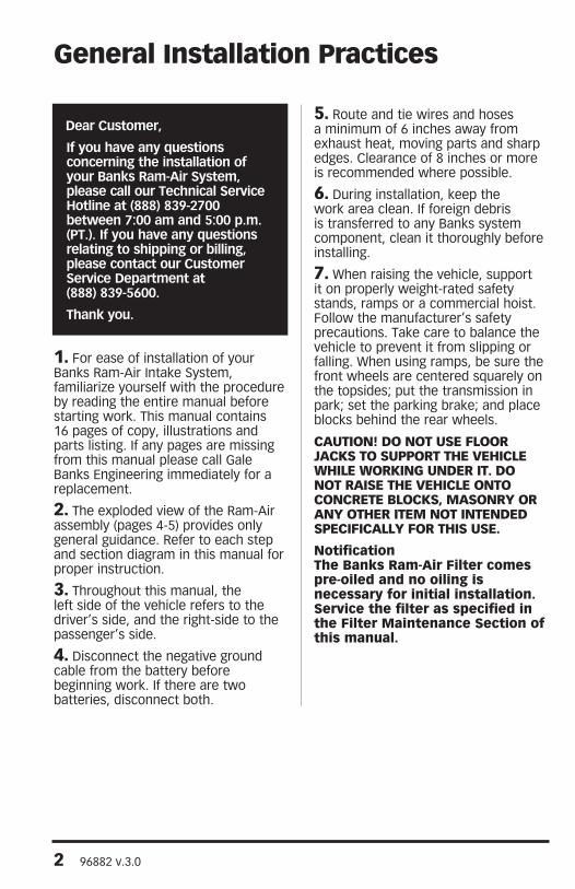
Dear Customer,
If you have any questions concerning the installation of your Banks Ram-Air System, please call our Technical Service Hotline at (888) 839-2700 between 7:00 am and 5:00 p.m. (PT.). If you have any questions relating to shipping or billing, please contact our Customer Service Department at (888) 839-5600.
Thank you.1
1. For ease of installation of your Banks Ram-Air Intake System, familiarize yourself with the procedure by reading the entire manual before starting work. This manual contains 16 pages of copy, illustrations and parts listing. If any pages are missing from this manual please call Gale Banks Engineering immediately for a replacement.
2. The exploded view of the Ram-Air assembly (pages 4-5) provides only general guidance. Refer to each step and section diagram in this manual for proper instruction.
3. Throughout this manual, the left side of the vehicle refers to the driver’s side, and the right-side to the passenger’s side.
4. Disconnect the negative ground cable from the battery before beginning work. If there are two batteries, disconnect both.
5. Route and tie wires and hoses a minimum of 6 inches away from exhaust heat, moving parts and sharp edges. Clearance of 8 inches or more is recommended where possible.
6. During installation, keep the work area clean. If foreign debris is transferred to any Banks system component, clean it thoroughly before installing.
7. When raising the vehicle, support it on properly weight-rated safety stands, ramps or a commercial hoist. Follow the manufacturer’s safety precautions. Take care to balance the vehicle to prevent it from slipping or falling. When using ramps, be sure the front wheels are centered squarely on the topsides; put the transmission in park; set the parking brake; and place blocks behind the rear wheels.
CAUTION! DO NOT USE FLOOR JACKS TO SUPPORT THE VEHICLE WHILE WORKING UNDER IT. DO NOT RAISE THE VEHICLE ONTO CONCRETE BLOCKS, MASONRY OR ANY OTHER ITEM NOT INTENDED SPECIFICALLY FOR THIS USE.
NotificationThe Banks Ram-Air Filter comes pre-oiled and no oiling is necessary for initial installation. Service the filter as specified in the Filter Maintenance Section of this manual.
General Installation Practices
2 96882 v.3.0
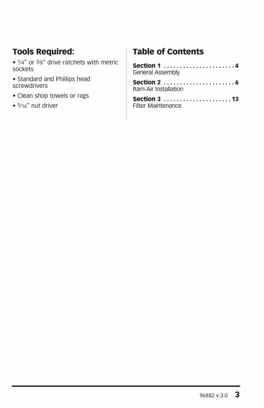
Tools Required: • 1⁄4” or 3⁄8” drive ratchets with metric sockets
• Standard and Phillips head screwdrivers
• Clean shop towels or rags
• 5⁄16” nut driver
Table of Contents
Section 1 . . . . . . . . . . . . . . . . . . . . . . 4General Assembly
Section 2 . . . . . . . . . . . . . . . . . . . . . . 6Ram-Air Installation
Section 3 . . . . . . . . . . . . . . . . . . . . . 13Filter Maintenance
96882 v.3.0 3
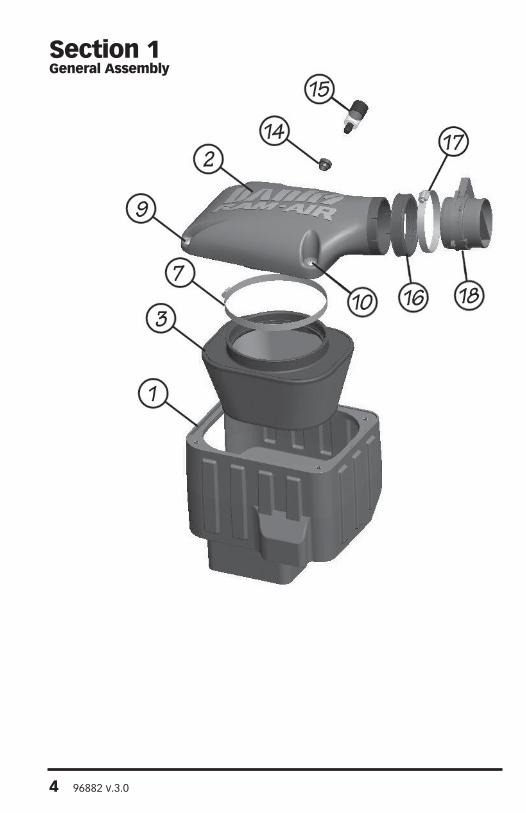
Section 1General Assembly
4 96882 v.3.0

Item Description Part# Qty
1 FILTER HOUSING, Ram-Air 42136 1
2 FILTER HOUSING COVER, Ram-Air 41803 1
3 AIR FILTER ELEMENT 42138 1
4 INTAKE TUBE, RAM-AIR 41804 1
4A* INTAKE TUBE, RAM-AIR (NOT SHOWN) 41805 1
5 HOSE, BELLOWS 94304 1
6 HOSE CLAMP, #64 92864 2
7 HOSE CLAMP, #128 92928 1
8* SPRING BAND CLAMP, 5⁄8” (NOT SHOWN) 92891 1
9 SCREW, #4 TRUSS HEAD, PHILLIPS, 5⁄16-18 X 3⁄4” 91226 2
10 SCREW, #4 TRUSS HEAD, PHILLIPS, 5⁄16-18 X 1 1⁄4”, SS 91242 2
11* PCV PLUG (NOT SHOWN) 92445 1
12* PCV HOSE, 3⁄8” (NOT SHOWN) 94136 1
13 FILTER MINDER PLUG (NOT SHOWN) 92440 1
14 STOCK FILTER MINDER RUBBER GROMMET / 1
15 STOCK FILTER MINDER / 1
16 STOCK SEAL GASKET, INLET / 1
17 STOCK HOSE CLAMP, INLET / 1
18 STOCK MASS AIR FLOW SENSOR / 1
19 HOSE CLAMP, THROTTLE BODY 92872 1
20** SEAL GASKET, THROTTLE BODY 93075 1
21 STOP DO NOT DISCARD, DECAL (NOT SHOWN) 96002 1
22 BANKS POWER UROCAL 96009 2
* For use with kit 41802. Truck models with electric fans. ** For use with kit 41801 & 41802.
96882 v.3.0 5
Use the Bill of Materials Chart and the General Assembly Drawing to reference component nomenclature and location. Use caution when working in the engine compartment. Make sure the engine has been OFF for several hours and cool.
You are about to install the Banks Ram-Air Intake System. Read and follow all steps before working on the vehicle. Some components from the stock air intake system will remain in service. Take care when removing stock air intake components to not damage them.
The images are for general reference only. Your vehicle application may look different.
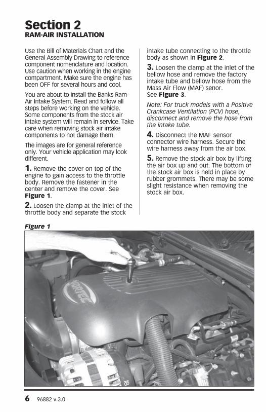
1. Remove the cover on top of the engine to gain access to the throttle body. Remove the fastener in the center and remove the cover. See Figure 1.
2. Loosen the clamp at the inlet of the throttle body and separate the stock
intake tube connecting to the throttle body as shown in Figure 2.
3. Loosen the clamp at the inlet of the bellow hose and remove the factory intake tube and bellow hose from the Mass Air Flow (MAF) senor. See Figure 3.
Note: For truck models with a Positive Crankcase Ventilation (PCV) hose, disconnect and remove the hose from the intake tube.
4. Disconnect the MAF sensor connector wire harness. Secure the wire harness away from the air box.
5. Remove the stock air box by lifting the air box up and out. The bottom of the stock air box is held in place by rubber grommets. There may be some slight resistance when removing the stock air box.
Section 2RAM-AIR INSTALLATION
Figure 1
6 96882 v.3.0

Figure 2
Figure 3
96882 v.3.0 7
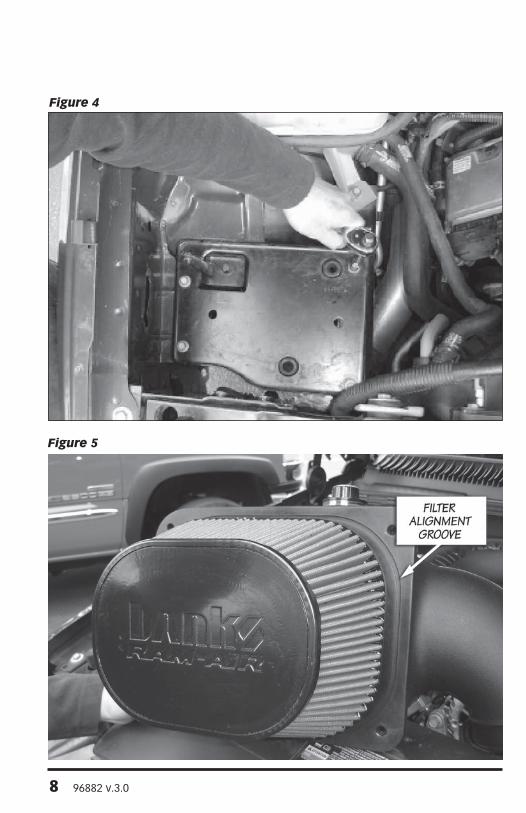
Figure 4
Figure 5
8 96882 v.3.0
6. From the stock air box, remove the stock air Filter Minder. Make sure to remove the stock air filter Minder’s rubber grommet as well.
7. Next, remove the stock air box tray. Remove the bolts accessible from the top of the engine compartment as shown then remove the stock air box tray. See Figure 4 . Keep the previously removed bolts for reassembly later in the installation process.
8. Locate your Banks Ram-Air Filter Housing from you kit. Align the Banks Ram-Air Filter Housing to fit parallel to fender edge. Install and tighten the previously removed bolts to secure the Banks Ram-Air Filter Housing.
Note: It may be necessary to adjust the radiator to overflow bottle hose to provide clearance for the Banks Filter Cover Housing. Adjust any other wires or hose as needed.
9. Locate the Banks Ram-Air Filter Housing Cover.
For vehicle models without a Stock Filter Minder,
Install the supplied Filter Minder Plug over the filter minder opening on the Banks Ram-Air cover.
For all truck models with a stock Filter Minder,
Install the stock air filter Minder’s rubber grommet into the Banks Ram-Air Filter Housing Cover. Once the rubber grommet is installed flush into the Banks Ram-Air Cover, then the filter Minder can be inserted into the rubber grommet. Make sure the air filter Minder is installed flush to the rubber grommet. 10. Locate the Banks Ram-Air Filter Element and filter hose clamp. Install the filter hose clamp on the filter.
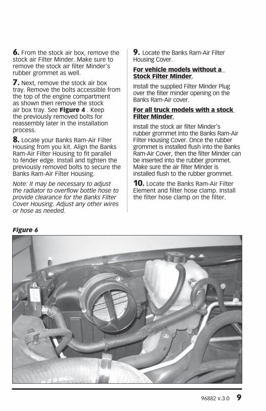
Figure 6
96882 v.3.0 9
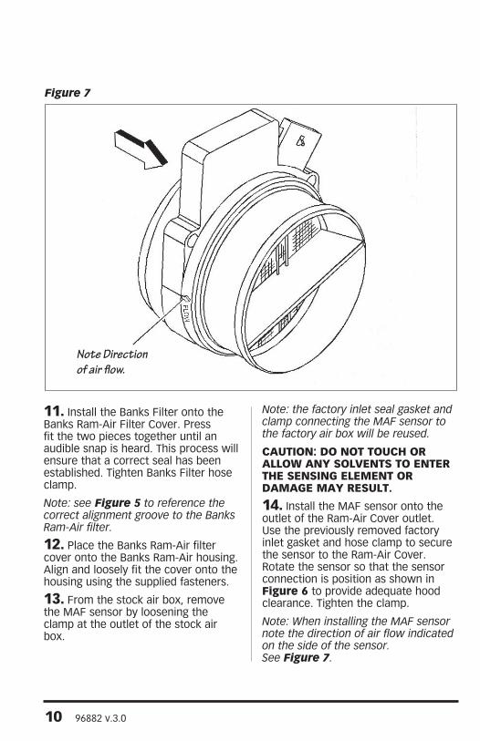
Figure 7
Note Direction of air flow.
11. Install the Banks Filter onto the Banks Ram-Air Filter Cover. Press fit the two pieces together until an audible snap is heard. This process will ensure that a correct seal has been established. Tighten Banks Filter hose clamp.
Note: see Figure 5 to reference the correct alignment groove to the Banks Ram-Air filter.
12. Place the Banks Ram-Air filter cover onto the Banks Ram-Air housing. Align and loosely fit the cover onto the housing using the supplied fasteners.
13. From the stock air box, remove the MAF sensor by loosening the clamp at the outlet of the stock air box.
Note: the factory inlet seal gasket and clamp connecting the MAF sensor to the factory air box will be reused.
CAUTION: DO NOT TOUCH OR ALLOW ANY SOLVENTS TO ENTER THE SENSING ELEMENT OR DAMAGE MAY RESULT.
14. Install the MAF sensor onto the outlet of the Ram-Air Cover outlet. Use the previously removed factory inlet gasket and hose clamp to secure the sensor to the Ram-Air Cover. Rotate the sensor so that the sensor connection is position as shown in Figure 6 to provide adequate hood clearance. Tighten the clamp.
Note: When installing the MAF sensor note the direction of air flow indicated on the side of the sensor. See Figure 7.
10 96882 v.3.0
15. Locate the Banks Ram-Air Intake tube and supplied throttle body seal gasket with hose clamp. Slide rubber grommet and hose clamp over the outlet of the intake tube.
16. Install the Banks Ram-Air Intake tube onto the throttle body. Do not tighten the clamp at this time.
17. For truck models with No PCV hose,
locate the supplied PCV plug and install over the PCV outlet in the intake tube. Secure the plug using the supplied spring band clamp.
For all other truck models with a PCV hose connection,
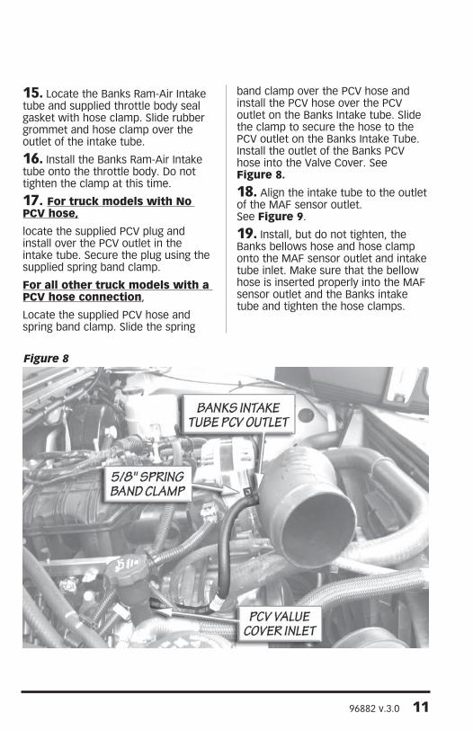
Locate the supplied PCV hose and spring band clamp. Slide the spring
band clamp over the PCV hose and install the PCV hose over the PCV outlet on the Banks Intake tube. Slide the clamp to secure the hose to the PCV outlet on the Banks Intake Tube. Install the outlet of the Banks PCV hose into the Valve Cover. See Figure 8.
18. Align the intake tube to the outlet of the MAF sensor outlet. See Figure 9.
19. Install, but do not tighten, the Banks bellows hose and hose clamp onto the MAF sensor outlet and intake tube inlet. Make sure that the bellow hose is inserted properly into the MAF sensor outlet and the Banks intake tube and tighten the hose clamps.
Figure 8
96882 v.3.0 11

20. Re-attach the MAF connector to the MAF sensor.
21. Affix the “Do Not Discard” sticker on or near the filter case (included with every Banks replacement element). Make sure you put the sticker in a highly visible place to alert your mechanic not to discard.
25. You system includes two (2) Banks Power decals designed to complement the Chevy emblems on the vehicles front doors.
22. Re-install the engine cover with the stock fastener. Make sure to go over all hose clamps for tightness and connectors for a sure fit. Make sure that the intake tube is not touching any engine components. Re-connect battery grounds. You have successfully completed the installation of the Banks Ram-Air Intake system.
Figure 9
12 96882 v.3.0
96882 v.3.0 13
OILED AIR FILTER ONLY
: The Banks Ram-Air Oiled Air Filter comes pre-oiled and no oiling is necessary for initial installation. Use Banks Ram-Air Filter Cleaning System (part#90094), available from Gale Banks Engineering to service the Air FIlter. Follow the instructions included with the cleaning sys-tem to clean and re-oil your Bank Ram-Air Oiled Air FIlter.
1. PRE-CLEANING
Tap the element to dislodge any large embedded dirt, then gently brush with a soft bristle brush. NOTE: If complete cleaning is not practical at this time, reoil the element and reinstall in your vehicle.
2. SPRAY-ON CLEANING
Spray air-filter cleaner liberally onto the entire element and let soak for 10 minutes.
3. PAN CLEANING
Large air-filter elements can be rolled or soaked in a shallow pan of air-filter cleaner. Remove immediately and let soak for approximately 10 minutes.
: NEVER use gasoline, steam, caustic solutions, strong detergents, high-pressure nozzles, or cleaning solvents to clean the filter element. All of these can cause harm to the filter media as well as SHRINK and HARDEN the rubber end caps.
4. RINSING
Rinse off the element with low-pressure water. Tap water is okay. Always flush from the clean side to dirty side. This removes the dirt
and does not drive it into the filter.
5. DRYING
Always dry naturally. After rinsing, shake off all excess water and let the element dry naturally.
6. AEROSOL OILING
After cleaning air filter always reoil before using. Spray air filter oil down into each pleat with one pass per pleat. Wait 10 minutes and re-oil any white spots still showing.
7. OILING HINTS
Never use a Banks Ram-Air filter without oil (the filter will not stop the dirt without the oil). Use only air filter oil. Air-filter oil is a compound of mineral and animal oil blended with special polymers to form a very efficient tack barrier. Red dye is added to show just where you have applied the oil. Eventually the red color will fade but the oil will remain and filter the air. NEVER USE Automatic Transmission Fluid. NEVER USE Motor Oil. NEVER USE Diesel Fuel. NEVER USE WD40, LPS, or other light-weight oils.
8. REINSTALL
Reinstall your Banks Ram-Air filter element with proper care. Make sure the element seats properly in the filter case. Install the cover making sure it’s in the right position. Tighten all the nuts, bolts, screws or clips to factory specifications.
9. DO NOT DISCARD
Affix the “Do Not Discard” sticker to the filter case (included with every Banks replacement element). Make sure you put the sticker in a highly visible place to alert your mechanic not to discard.
10. PERFORMANCE HINTS
Service every 50-100,000 miles on
Section 3AIR FILTER CLEANING INSTRUCTIONS
Gale Banks Engineering 546 Duggan Avenue • Azusa, CA 91702 (626) 969-9600 • Fax (626) 334-1743
Product Information & Sales: (888) 635-4565Customer Support: (888) 839-5600 Installation Support: (888) 839-2700
bankspower.com
street-driven applications. Service more often in offroad or heavy-dust conditions. If an air-filter restriction gauge is installed, then change the element when the air-filter restriction reaches 18”–H2O.
: Extremely fine dust from agriculture or offroad use will pull the oil from the element. Frequent reoiling of the element’s clean side might be required. Completely service when practicable. For extra protection use an air-filter sealing grease on rubber ends of the element. Service only with air-filter cleaner and air-filter oil.
DRY FILTER CLEANINGClean every 50-100,000 miles on street-driven applications. Clean more often in offroad or heavy-dust conditions. If an air-filter restriction gauge is installed, then change the element when the air-filter restriction reaches 18”–H2O.
1. PRE-CLEANING
Carefully tap the air filter element to dislodge any large embedded dirt or debris.
2. CLEANING
Spray an appropriate DRY AIR-FILTER CLEANER SOLUTION liberally onto both sides of the entire filter element with the majority applied to the dirty side. Soak for 10 minutes. Do not allow the DRY AIR-FILTER CLEANER SOLUTION to dry on the air filter.
: NEVER use gasoline, steam, caustic solutions, strong de-tergents, high-pressure nozzles, or cleaning solvents to clean the filter element. All of these can cause harm to the filter media as well as SHRINK and HARDEN the rubber end caps.
3. RINSING
Rinse the filter element with cool or warm (not hot) water from the clean side out in order to flush the dirt out of the filter. It may be necessary to use your fingers on the hose to apply light water pressure. Repeat steps 2 and 3, until the water flowing through the media is completely clear of any dirt and debris.
4. DRYING
After rinsing, gently shake off exces-sive water and allow to dry naturally. Re-install the filter onto the intake sys-tem, airbox or custom assembly once it is dry or just slightly damp. Follow all original installation instructions.
5. REINSTALL
Reinstall your Banks Ram-Air filter element with proper care. Make sure the element seats properly in the filter case. Install the cover making sure it’s in the right position. Tighten all the nuts, bolts, screws or clips to factory specifications.
6. DO NOT DISCARD
Affix the “Do Not Discard” sticker to the filter case (included with every Banks replacement element). Make sure you put the sticker in a highly visible place to alert your mechanic not to discard.
7. PERFORMANCE HINTS
Service every 50-100,000 miles on street-driven applications. Service more often in offroad or heavy-dust conditions. If an air-filter restriction gauge is installed, then change the element when the air-filter restriction reaches 18”–H2O.
-END, SECTION 3-