Owner’sMa with Installation...
52
©2012 Gale Banks Engineering Owner’sManual with Installation Instructions Banks Brake with CBC/SmartLock ® Exhaust Brake System 2004-2007 Dodge Cummins ISB Pickup Trucks THIS MANUAL IS FOR USE WITH CBC/SMARTLOCK EXHAUST BRAKE SYSTEMS 55225, 55226, 55229 Gale Banks Engineering 546 Duggan Avenue • Azusa, CA 91702 (626) 969- 9600 • Fax (626) 334-1743 Product Information & Sales: (888) 635-4565 bankspower.com 03/16/12 PN 97055 v.8.0
Transcript of Owner’sMa with Installation...

©2012 Gale Banks Engineering
Owner’sManualwith Installation Instructions
Banks Brake with CBC/SmartLock®
Exhaust Brake System
2004-2007 Dodge Cummins ISB Pickup TrucksTHIS MANUAL IS FOR USE WITHCBC/SMARTLOCK EXHAUST BRAKE SYSTEMS 55225, 55226, 55229
Gale Banks Engineering 546 Duggan Avenue • Azusa, CA 91702 (626) 969-9600 • Fax (626) 334-1743
Product Information & Sales: (888) 635-4565
bankspower.com
03/16/12 PN 97055 v.8.0

2 97055 v.8.0
Banks iQ System(P/N 61148-61149)
- 5” touchscreen interface that can control the Banks Diesel Tuner on the fly.
- Interchangable gauge display, read and clear codes, monitor engine diagnostics, log data, time your vehicles runs and much more.
Banks Monster® Exhaust SystemSingle (P/N 48640-48643, 48700, 48701, 48708)Duals (P/N 48702-48707, 48709)Sport (P/N 48777-48780)
- Increases exhaust flow, cuts backpressure, lowers exhaust gas temperatures (EGTs) and increases power.
Banks Ram-Air Intake System(P/N 42145)
- Increases your airflow over stock. - Adds power, improves fuel economy, lowers EGTs and reduces smoke.
Banks Ram-Air Intake Super-Scoop(P/N 42190-42191)
- Adds cooler denser air to the Ram-Air Intake housing, further increasing fuel economy, reducing smoke and lowers EGTs.
Banks Monster-Ram(P/N 42765-42766)
- Increased flow from intercooler- Raises boost without increasing
backpressure at the turbine
Big Hoss Intake Manifold System(P/N 42747)
- Increases flow and provides more uniform air distribution to the engine for more available power at a given boost level.
Banks Techni-Cooler® System(P/N 25980-25981)
- Provides increased air flow to the engine by increasing air density for more increased power, lower EGTs and improved fuel economy.
Banks SmartLock(P/N 55270)
- Reduces wear on transmission - Locks Torque Converter and raises
trans-line pressure- Works with Banks Exhaust Brake
Boost and Pyro Gauges (P/N 64507)
- Keep your engine safe by monitoring vital engine parameters.
Product available from Banks Power for the ‘03-07 Dodge 5.9L
Super-Scoop® Banks Ram-Air®
Intake
Techni-Cooler® System
Advanced Diesel Tuners
Monster-Ram
DynaFact® Instrumentation
Banks Billet™ Torque ConverterBigHead®
Wastegate
Banks Brake®
Monster®
Exhaust
Banks iQBanks Bullet™

97055 v.8.0 3
Banks Billet Torque Converter(P/N 72515)
- Higher torque capacity over stock- Lockup clutch is slip-resistant so transmission fluids stay cooler and transmission life is prolonged.
Banks Bullet(P/N 66522-66523)
- Adds power safely to your vehicle- Displays critical engine functions- Engine safeguards- Change power levels on-the-fly
Banks Diesel TunerEconoMind w/switch (P/N 63725, 63793, 63795, 64507) EconoMind w/iQ (P/N 63807, 63808, 63817, 63818)Six-Gun w/switch (P/N 61022, 63797)Six-Gun w/iQ (P/N 63809, 63819)
- Adds power safely to your vehicle
- Engine and transmission safeguards
- Change power levels on-the-fly
Thermocouple- Add a temperature limiting function to your Diesel Tuner .
Banks Speed-Loader (P/N 62981)
- Furthers the power output of the Banks Six-Gun and provides EGT limiting safety.
Banks BigHead® Actuator(P/N 24331)
- Achieves a higher peak boost over stock and gives you precise boost control that gives you crisp acceleration and more mid-range pulling power.
Banks Stinger Systems(P/N 49692-49699, 49708-49711, 49716-49721)Contains:
- Ram-Air Intake system- Monster Exhaust (single or dual)- EconoMind Tuner w/ Banks iQ- Big Head Wastegate Actuator
Banks PowerPack Systems(P/N 49700-49707, 49712-49715, 49722-49727)Contains:
- Ram-Air Intake system- Monster Exhaust (single or dual)- EconoMind Tuner w/ Banks iQ- Big Head Wastegate Actuator- Monster-Ram- Techni-Cooler System
Banks Six-Gun Bundle(P/N 49728-49735, 49744-49747, 49752-49757)Contains:
- Ram-Air Intake system- Monster Exhaust (single or dual)- Six-Gun Tuner w/ Banks iQ- Big Head Wastegate Actuator
Banks Big Hoss Bundle(P/N 49736-49743, 49748-49751, 49758-49763)Contains:
- Ram-Air Intake system- Monster Exhaust (single or dual)- Six-Gun Tuner w/ Banks iQ- Big Head Wastegate Actuator- Monster-Ram- Techni-Cooler System
For More Information please call (888) 635-4565or Visit us online @ www.bankspower.com
4 97055 v.8.0
Gale Banks Engineering Inc. (hereafter “SELLER”), gives Limited Warranty as to description, quality, merchantability, fitness for any particular purpose, productiveness, or any other matter of SELLER’s product sold herewith. The SELLER shall be in no way responsible for the product’s open use and service and the BUYER hereby waives all rights except those expressly written herein. This Warranty shall not be extended or varied except by written instrument signed by SELLER and BUYER.
Please see enclosed warranty information card, or go to ww.bankspower.com/warranty, for warranty information regarding your product. Parts or devises outside the products kit are not covered under Gale Banks Engineering warranty. All products that are in question of Warranty must be returned shipping prepaid to the SELLER and must be accompanied by a dated proof of purchase receipt. All Warranty claims are subject to approval by Gale Banks Engineering Inc.
Under no circumstance shall the SELLER be liable for any labor charged or travel time incurred in diagnosis for defects, removal, or reinstallation of this product, or any other contingent expense.
Under no circumstances will the SELLER be liable for any damage or expenses incurred by reason of the use or sale of any such equipment.
WARNING! The Vacuum Pump must never be run open to the atmosphere, as this will damage the Pump diaphragm. The Pump must always be connected to the Vacuum Solenoid or it’s vacuum nipple must be plugged. The warranty on the Pump will be voided if the Pump is allowed to run open to the atmosphere.
Banks Brake system 55225 for some 2004 thru 2005 models and system 55226 for 2006 thru 2007 models will be required for vehicles equipped with a transmission throttle valve assembly. Please Verify that your vehicle is equipped with a transmission throttle valve assembly and that NO Throttle Position sensor assembly is installed to have the CBC/SmartLock function properly. See Figure 1 & 2.
For some 2004 model vehicles, if your vehicle is not equipped with a transmission throttle valve assembly, but has a throttle position sensor (TPS) located in the engine compartment on the driver side and the three (3) transmission connectors on the driver’s side of the transmission as shown in Figure 2 and 3 you need system part # 55229 for your Banks CBC/SmartLock to function properly.
Limitation of Warranty
In the event that the buyer does not agree with this agreement:
The buyer may promptly return this product, in a new and unused condition, with a dated proof-of- purchase, to the place-of-purchase within thirty (30) days from date-of-purchase for a full refund, less shipping and/or restocking fee.
The installation of this product indicates that the buyer has read and understands this agreement and accepts its terms and conditions.

97055 v.8.0 5
Figure 2 Engine Compartment Driver Side
Figure 1 Driver Side, Top of Transmission
6 97055 v.8.0
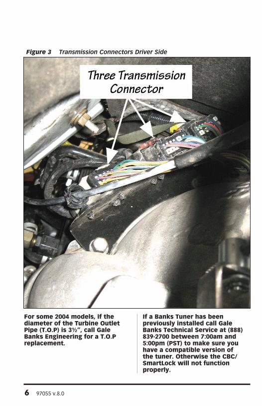
For some 2004 models, if the diameter of the Turbine Outlet Pipe (T.O.P) is 3½“, call Gale Banks Engineering for a T.O.P replacement.
If a Banks Tuner has been previously installed call Gale Banks Technical Service at (888) 839-2700 between 7:00am and 5:00pm (PST) to make sure you have a compatible version of the tuner. Otherwise the CBC/SmartLock will not function properly.
Figure 3 Transmission Connectors Driver Side
97055 v.8.0 7
Dear Customer,
Your new Banks Brake with CBC/SmartLock is a uniquely designed exhaust brake with electronic controls, designed to achieve the optimum level of braking from your vehicle’s engine.
If you have any questions concerning the installation and operation of the Banks CBC/SmartLock Exhaust Brake, please call our Technical Service Hotline at (888) 839-2700 between 7:00 am and 5:00 PM (PST). IF YOU HAVE ANY QUESTIONS RELATING TO SHIPPING OR BILLING, PLEASE CONTACT OUR CUSTOMER SERVICE DEPARTMENT AT (888) 839-5600.
Thank you.
1. For ease of installation of your Banks CBC/SmartLock Exhaust Brake System, familiarize yourself with the procedure by reading the entire manual before starting work.
2. Inspect all components supplied for any foreign material that may have entered during shipping and handling.
3. The installation should be performed at a time when the vehicle has been allowed to completely cool. This installation requires the installer to work near surfaces that may remain hot after the vehicle has been run. Failure to allow the vehicle to cool may result in personal injury.
4. Throughout this manual, the left side of the vehicle refers to the driver’s side, and the right side refers to the passenger’s side of the vehicle.
5. Throughout this manual, major components of the Banks products are capitalized to make it easier to identify them.
6. Pay particular attention to the routing of wires. Keep them away from exhaust heat, moving parts and sharp edges that may cause damage. Route or tie away from critical areas as required. Keep all wires a minimum of 6” from hot exhaust parts, 8” or more is recommended whenever possible.
7. During installation, keep the work area clean. If foreign debris is transferred to any Banks system component, clean it thoroughly before installing.
WARNING! Never work under any vehicle supported only by a jack of any kind. DO NOT USE concrete blocks or other masonry items that may collapse under the vehicle weight.
WARNING! The Vacuum Pump must never be run open to the atmosphere, as this will damage the Pump diaphragm. The Pump must always be connected to the Vacuum Solenoid or it’s vacuum nipple must be plugged. The warranty on the Pump will be voided if the Pump is allowed to run open to the atmosphere.
General Installation Practices

8 97055 v.8.0
Tools Required: 1• ⁄2” and 3⁄4” drive ratchets with inch
and metric sockets and 1⁄2” and 3⁄8” drive extension
1• ⁄2” breaker bar
Inch and metric combination or • open-end wrenches
Standard screwdriver•
Clean shop towels or rags•
Pliers•
Utility knife•
Electric drill• 1• ⁄2” drill bit
Wire cutters•
Inch-pound and foot-pound torque • ratchets
Penetrating oil or light lubricant • spray
Torx T-10 tool•
Note for 2006-07 trucks: Before starting, it may be necessary to have an extra bottle of coolant on hand to top off the radiator when finished installing the Banks CBC/SmartLock exhaust Brake System. Follow the manufacture’s air bleeding procedures.
Section 1 . . . . . . . . . . . . . . . . . . . . .7 General Assembly and Bill of Materials
Section 2 . . . . . . . . . . . . . . . . . . . . 11 Banks Exhaust Brake Installation
Section 3 . . . . . . . . . . . . . . . . . . . . 15 Vacuum Boost Actuator Installation
Section 4 . . . . . . . . . . . . . . . . . . . . 20 Vacuum Solenoid Installation
Section 5 . . . . . . . . . . . . . . . . . . . . 22 Vacuum Pump Installation
Section 6 . . . . . . . . . . . . . . . . . . . . 24 CBC/SmartLock and Wiring Harness Installation
Section 7 . . . . . . . . . . . . . . . . . . . . 34 Brake Enable and Overdrive Disable Switch Installation
Section 8 . . . . . . . . . . . . . . . . . . . . 40 Functional Testing
Section 9 . . . . . . . . . . . . . . . . . . . . 41 Safety and Operation/ Driving Tips
Section 10 . . . . . . . . . . . . . . . . . . . 42 Troubleshooting
Replacement belt numbers:Banks 65120
Gatorback 4081295
Napa 25081298
Dayco 5081300
Mopar 53041270AA
Cummins 3947077
Note: If you cannot find the above part numbers, ask for a belt that fits 2004- 07 Ford e350-450 econoline van with 6.0L Diesel engine and single alternator
Table of Contents

97055 v.8.0 9
Section 1General Assembly
Figure 4 Wiring Harness 55406
Figure 5

10 97055 v.8.0
Figure 6
Figure 7

97055 v.8.0 11
Bill of Materials
Description P/N Kit 55225 Kit 55226 Kit 55229Assembly, Brake Housing 55045 1 1 1
Vacuum Pump 55176 1 1 1
Bracket, Vacuum Pump 55177 1 1 1
Vacuum Boost Actuator 55071 - - 1
Hex Bolt, Washer Head, Black, M8x1.25 x 25mm
91809 3 3 3
Hex Bolt, Washer Head, Black, M8x1.25 x 40mm
91815 4 4 4
Vacuum Solenoid 55138 1 1 1
Hex Bolt, Zinc, M6x1.00 x 25mm 91742 1 1 1
Washer, SAE, Flat, Zinc, 1⁄4” 91102 1 1 1
Nut, Nylock, M6 x 1.0, Zinc 91771 1 1 1
Computerized Brake Control, 2004 -2005
55272 1 - 1
Computerized Brake Control, 2006-07
55273 - 1 -
Wiring Harness, 2004 With No Throttle Valve Assembly
55410 - - 1
Wiring Harness, 2004-2005 with Throttle Valve Assembly
55406 1 - -
Wiring Harness, 2006-07 55407 - 1 -
Mini Fuse Clip 62052 1 1 1
Switch Assemblies 62130 2 2 2
OBD II Interface Cable, 2004-2005 62585 1 - 1
OBD II Interface Cable, 2006-07 62586 - 1 -
Heater Core Tube, 2006-07 25570 - 1 -
Hose, 7⁄32” 1.5 ft 94128 1 1 1
Kit # 55229 for use with models with No Transmission Throttle Valve Assembly

12 97055 v.8.0
Description P/N Kit 55225 Kit 55226 Kit 55229Hose, 1/4” 9 ft 94121 - - 1
Hose, 5⁄16” 5 ft 94129 1 1 1
Vent Hose Assembly 94450 - - 1
Hose Fitting, 1/8” NPT x 3/16”, 90-Degree Elbow
92121 - - 1
Brass Tee Fitting, 1/4” 92243 - - 2
Spring Band Clamp, 3/8” 92875 - - 5
Belt, Serpentine, Vacuum Pump 65120 1 1 1
Urocal, Banks Power, Small 96009 2 2 2
Cable Ties, 7” 62010 25 25 25
Module Bracket Kit- Optional (All) 55298
Kit # 55229 for use with models with No Transmission Throttle Valve Assembly
-END SECTION 1-
Bill of Materials (continued)

97055 v.8.0 13
Section 2Banks Exhaust Brake Installation
1. As a precaution, disconnect the ground of the battery (if there is more than one battery, disconnect both grounds).
2. Raise the vehicle and support it with properly weight rated safety stands or a commercial hoist. Follow the manufacturer’s safety precautions. Take care to support the vehicle to prevent it from slipping or falling. Place the transmission in park; set the parking brake and place blocks behind the rear wheels.
3. Remove the front wheels and the front wheel well splash shields.
If equipped, detach the ABS wire that is clipped on the passenger side splash shield before completely removing the shield to avoid damage to the wire.
4. Remove the exhaust elbow that is attached to the turbo outlet by loosening the V-clamps and slide them off the lip. Spray with penetrating lubricant to ease removal. See Figure 8.
Note: It may be necessary to loosen or remove the exhaust support from the transmission to provide extra clearance.
Push the exhaust pipe to the rear of the vehicle slightly to allow the elbow to be removed. Slide the elbow towards the rear of the vehicle to allow the alignment pins in the turbo to come free.
If the elbow doesn’t come lose, then it may be necessary to break it lose from the alignment pins. Wear appropriate eye protection and firmly strike the elbow with a hammer or light sledge hammer.
Note: Retain the factory V-clamps for use later. the alignment pins will have to be removed or broken lose from the turbo’s outlet flange. Make sure the turbo’s outlet flange surface is flat so that it doesn’t interfere with proper exhaust sealing.
Figure 8 Removal of exhaust elbow

14 97055 v.8.0
2006-07 trucks proceed to Step 5.
2004-05 proceed to Step 8.
5. For 2006-07 trucks, the heater core tube that is above the exhaust pipe will have to be replaced with Banks Heater Core Tube to provide additional clearance for the Brake.
6. Drain the radiator fluid into a suitable container to be re-used. Loosen the hose clamps and remove the heater hoses from the heater core tube. Remove the two (2) nuts and one (1) bolt that attach the coolant line to the engine. See Figure 9 for the passenger side nut and bolt.
Note: the third nut on the coolant line is accessible from the driver’s side wheel well (Figure 10).
7. Replace the factory heater core tube with the Banks Heater Core Tube. Install and tighten the nuts and bolt. Re-install the heater hoses making
sure that they are properly inserted on the pipe. Slide the hose clamps back into place. Refill the radiator and follow manufacture’s air bleeding procedures.
8. The transmission dip stick tube needs to be adjusted to allow for added clearance for the lower exhaust brake V-clamp. Loosen or remove the bolt(s) that hold it in place and adjust as needed after the Banks Brake is in.
9. Slide the larger sized factory V-clamp on the exhaust pipe.
10. Locate the supplied Banks Exhaust Brake assembly and slide the factory V-clamp over the inlet of the brake. Orientate your brake as shown in Figure 11.
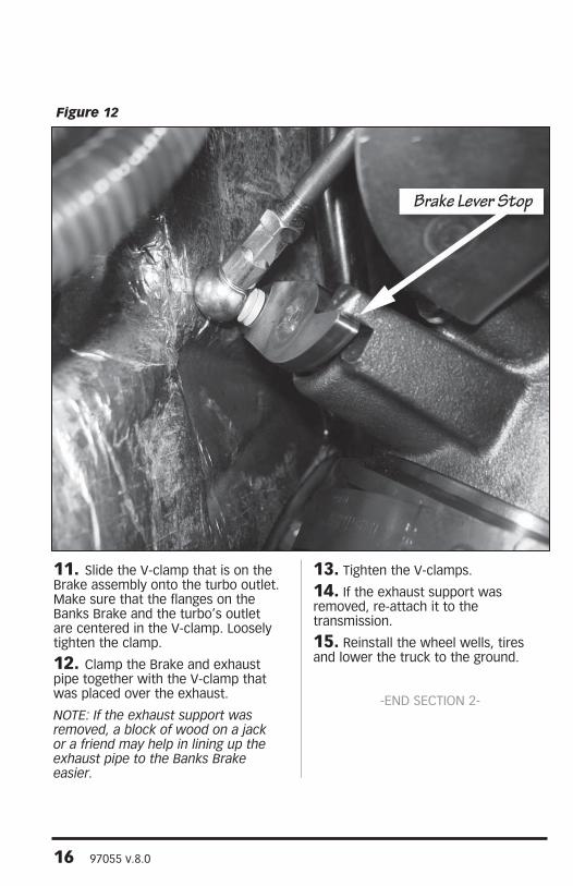
Note: Do not worry if the Brake actuator arm touches the fire wall insulation. this will not effect the action of the Brake. Make sure that the Brake lever is fully seated against it’s stop. See Figure 12.
Figure 9 Passenger Side

97055 v.8.0 15
Figure 11 exhaust Brake orientation
Figure 10 Driver Side
16 97055 v.8.0
11. Slide the V-clamp that is on the Brake assembly onto the turbo outlet. Make sure that the flanges on the Banks Brake and the turbo’s outlet are centered in the V-clamp. Loosely tighten the clamp.
12. Clamp the Brake and exhaust pipe together with the V-clamp that was placed over the exhaust.
Note: If the exhaust support was removed, a block of wood on a jack or a friend may help in lining up the exhaust pipe to the Banks Brake easier.
13. Tighten the V-clamps.
14. If the exhaust support was removed, re-attach it to the transmission.
15. Reinstall the wheel wells, tires and lower the truck to the ground.
-END SECTION 2-
Figure 12

97055 v.8.0 17
Section 3Vacuum Boost Actuator Installation
If installing kit 55229 continue with this section,
For kits 55225 and 55226 skip to Section 4.
Note: the following instructions assume that a Banks Brake System has been previously installed on the vehicle.
1. Locate the two (2) supplied rubber 1/4” hoses for the Vacuum Boost Actuator assembly (Black and Blue hose). Route one end of the rubber hoses from the top left side of the engine compartment down to the left side of the transmission. Route just enough to reach the rear of the transmission. Secure the other end of the hoses at the top of the engine compartment.
2. Raise the vehicle and support it with properly weight rated safety stands or a commercial hoist. Follow the manufacturer’s safety precautions.
Take care to support the vehicle to prevent it from slipping or falling. Place the transmission in park; set the parking brake and place blocks behind the rear wheels.
3. Locate the two (2) supplied 90-degree barb fittings and actuator assembly. Screw the 90-degree barb fittings onto the actuator assembly. Do not over tighten.
4. Disconnect the cable from the kick-down lever on the left side of the transmission case as shown in Figure 13.
5. Disconnect the return spring attached to the kick-down lever as shown in Figure 14. Retain the spring for reuse later.
6. Loosen the lock bolt and remove the factory kick-down lever from the throttle valve shaft as shown in Figure 15.
Figure 13

18 97055 v.8.0
Figure 14
Figure 15

97055 v.8.0 19
7. Remove the mounting bolt from the transmission case and install the line pressure boost actuator and bracket as shown in Figure 16. Temporarily finger-tighten the bolt to allow for adjustment.
8. Slide the actuator control lever over the throttle valve shaft and tighten the bolt. Re-attach the return spring to the transmission case actuator control bracket as shown in Figure 17. Re-attach the kick-down cable removed in step 4. Actuate the lever by hand several times and ensure there is no binding or the system will fail to function properly. There should be a small gap between the knurling and the slider when the actuator rod is fully extended.
Adjust the length of the actuator rod if necessary by loosening the nut on the rod. Increase or decrease the length of
the rod by turning it. Adjust the rod to the correct length. Secure the rod by tightening the nut.
Also ensure the return spring is sufficient to return the lever to a stop. If not, use a pair of side cutters to shorten the spring as necessary. Remove 1/4” at a time until the spring is able to return the lever to the stop. Use needle-nosed pliers to reform the hooked ends after they are cut. The rear-mounting bracket can be loosened and rotated to eliminate binding. Apply general purpose water resistant lithium grease to all sliding surfaces, such as the actuator shaft extension, to reduce sliding friction.
9. Securely mount the actuator cylinder by tightening the bolt (in step 7) on the transmission case to 25 ft-lbs. Ensure the lock bolt on the lever is also tightened.
Figure 16

20 97055 v.8.0
10. Locate two spring band clamps and slide over the rubber hose that were routed down to the left side of the transmission in step 1.
11. Locate the blue hose, this hose will connect to the vacuum solenoid in Section 4, and insert the hose in the rear 90-degree barb fitting. Secure the hose to the fitting by sliding the spring band clamp into place. See Figure 18.
12. Locate the black hose, this hose will be the vent line for the boost actuator, and insert the hose in the front 90-degree barb fitting. Secure the hose to the fitting by sliding the spring band clamp into place. See Figure 18.
13. Secure the two rubber hose away from any heat source or moving components with zip ties up to the left side of the engine compartment.
14. Lower the vehicle.
15. From the top of the engine compartment locate the black hose that will serve as the vent line for the boost actuator. Secure the hose to the wiring harness on the rear rail on the driver side using a zip tie.
16. Locate the breather assembly and a spring band clamp. Slide the spring band clamp over the vent line hose. Insert the breather assembly into the hose. Secure the breather assembly to the hose by sliding the spring band clamp into place. See Figure 19.
17. The blue hose will be connected to the vacuum solenoid in the next section. Route the hose along the rail to the right side of the engine compartment over the Banks Brake.
-END OF SECTION 3-
Figure 17

97055 v.8.0 21
Figure 18 Vacuum Boost Actuator Hose connections
Figure 19 Vent Line with Breather Assembly, Left Side engine Compartment

22 97055 v.8.0
1. Locate the rail along the rear of the engine compartment. Remove the push-in retainer that is closest over the exhaust brake with an upholstery tool or screw driver.
2. Locate the supplied Banks Vacuum Solenoid along with it’s 1⁄4” split and flat washers, M6 x 1.0mm x 25mm bolt, and M6 x 1.0 nut. Slide the 1⁄4” flat washer onto the bolt and install the Solenoid at the location where the push-in retainer was previously removed. See Figure 20 & 21. Slide the 1⁄4” split washer and nut onto the bolt and tighten.
3. Using the supplied 7⁄32” hose for the Exhaust Brake slip one end onto the Banks Exhaust Brake Actuator nipple. See Figure 22. Make sure it is secured properly. Run the tubing up along the transmission dipstick tubing to the left side nipple of the Solenoid (Port 2).
If installing kits 55225 & 55226, Cut the tubing to length and slide fully onto Port 2 of the Solenoid. Secure the hose away from sharp, hot and/or moving parts with a cable tie.
If installing kit 55229, Run the blue hose from the vacuum boost actuator to the left side nipple of the solenoid (port 2). Cut the blue hose
to length. Locate the barb tee-fitting and a spring band clamp. Slide the spring band clamp over the hose and insert the middle nipple on the tee-fitting onto the blue hose. Secure the hose with the spring band clamp. Take the hose from the Banks brake and route to the tee-fitting. Cut the hose to length and slide a spring band clamp over the hose. Insert the hose into the tee-fitting. Secure the hose to the tee-fitting with the spring band clamp. Take the remaining hose cut from the Banks brake and insert one end into the tee-fitting. Slide a spring band clamp to secure the hose to the tee-fitting. Run the other end of the hose to the left side nipple of the solenoid (port 2). Cut the tubing to length and slide fully onto Port 2 of the Solenoid. Secure the hose away from sharp, hot and/or moving parts with a cable tie.
4. Insert the supplied 5⁄16” hose onto the right side nipple of the Solenoid (Port 1). Run the hose along the wiring harness to the intake on the driver’s side of the engine.
Note: Do not secure the vacuum tubing yet. It will be secured in Section 5, Step 4
-END OF SECTION 4-
Figure 20 For Models with throttle Valve Assembly (some 2004 thru 2007 models)
Section 4Vacuum Solenoid Installation

97055 v.8.0 23
Figure 22
Figure 21 For models with no throttle Valve Assembly (some 2004)

24 97055 v.8.0
1. Use a 1⁄2” ratchet or breaker bar to loosen the tensioner pulley to create slack on the drive belt. Remove the factory drive belt.
2. Locate the Banks Vacuum Pump and attach it to the supplied Vacuum Pump Bracket using the three M8 x 1.25 x 25mm supplied bolts. Torque them to 18 ft-lbs (25 N*m). See Figure 23.
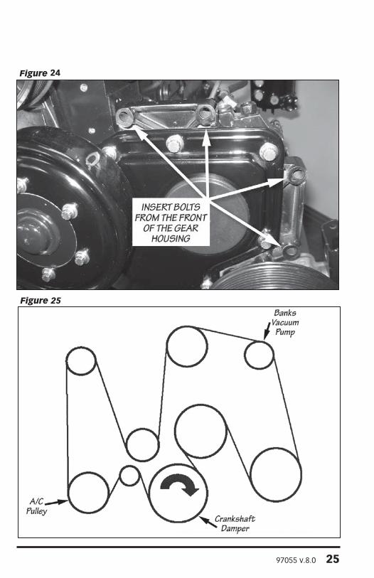
3. With the four supplied M8 x 1.25 x 40mm bolts, mount the Vacuum Pump assembly to the rear of the gear housing (Figure 24). Torque the bolts to 18 ft-lbs (25 N*m).
Note: to provide additional clearance when attaching the vacuum pump to the gear housing, you may need to remove the radiator support bracket. this will allow the fan shroud some freedom to move.
4. Route the 5⁄16” hose from the Vacuum Solenoid under the intake and to the Vacuum Pump nipple. Cut the hose to length. Attach the hose to the Pump. Secure the hose to the factory wiring harness making sure it is away from any heat source, sharp edges, and/or moving parts. Make sure not to crimp or pinch the hose closed.
5. With the supplied Drive Belt, route the Belt as shown in Figure 25. Use the ½” drive ratchet or breaker bar on the belt tensioner to allow the new Belt to slide into place.
Note: If your vehicle does not have an air conditioning pulley, you may have to purchase a different accessory drive belt. Its length will need to be 113.9” (2,892mm).
6. Make sure the Belt is properly aligned around all the pulleys and release the tensioner. See Vacuum Pump warning on page 5.
-END OF SECTION 5-Figure 23
Section 5Vacuum Pump Installation
97055 v.8.0 25
Figure 25
Figure 24

26 97055 v.8.0
1. Remove the fuse box cover, located in the front driver’s side of the engine compartment. Locate mini-fuse #50 for 2004-05 trucks (Figure 26) or #28 for 2006-07 trucks (Figure 27) and remove it.
2. Install the mini-blade fuse tap onto the removed mini fuse as shown in Figure 28. Re-install the mini fuse with the attached blade tap into fuse box.For 2004-05 trucks, install the fuse tap in the #50 spot closest to the firewall as seen in Figure 26.
For 2006-07 trucks, install the mini-auto blade tap in the #28 spot closest to the engine. This is the “hot” side of the circuit. See Figure 27.
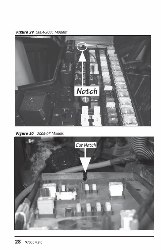
3. Cut a small notch in the fuse box cover and base to avoid a pinched or stressed wire.
For 2004-05 trucks, cut the notch at the edge closest to the firewall. See Figure 29.
For 2006-07 trucks, cut the notch at the edge closest to the engine. See Figure 30.
Note: If a Banks Six-Gun or ottoMind Diesel tuner has been installed in the vehicle, disconnect the tuner’s red Power terminal wire from the fuse tap and connect the CBC/SmartLock’s red Fuse Connector wire from the Banks exhaust Brake Harness. Connect the tuner’s Power terminal wire to the exhaust Brake Harness, (optional) tuner Power Connector. See Figure 4.
Figure 26 2004-2005 Models
Section 6CBC/SmartLock and Wiring Harness Installation

97055 v.8.0 27
Figure 28 Fuse tap Installation
Figure 27 2006-07 Models
28 97055 v.8.0
Figure 30 2006-07 Models
Figure 29 2004-2005 Models

97055 v.8.0 29
Figure 32 All Models CBC Smartlock Mounting Location
Figure 31 Ground Wire Attachment Location
30 97055 v.8.0
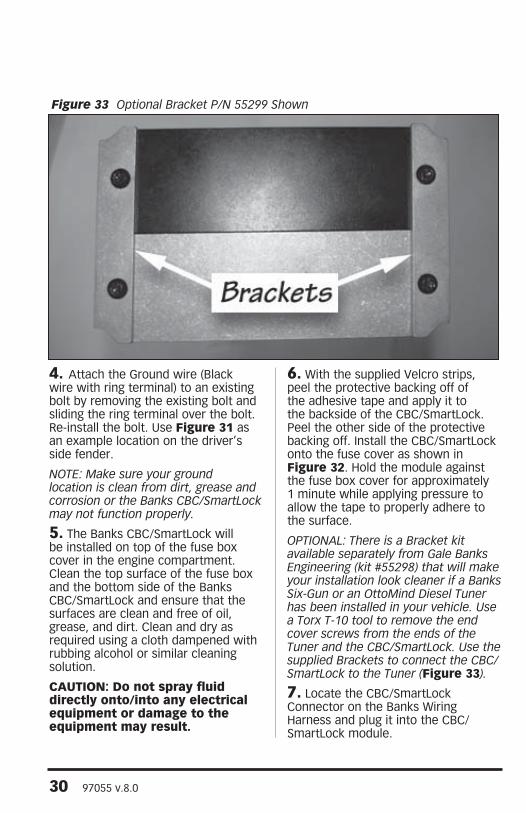
4. Attach the Ground wire (Black wire with ring terminal) to an existing bolt by removing the existing bolt and sliding the ring terminal over the bolt. Re-install the bolt. Use Figure 31 as an example location on the driver’s side fender.
Note: Make sure your ground location is clean from dirt, grease and corrosion or the Banks CBC/SmartLock may not function properly.
5. The Banks CBC/SmartLock will be installed on top of the fuse box cover in the engine compartment. Clean the top surface of the fuse box and the bottom side of the Banks CBC/SmartLock and ensure that the surfaces are clean and free of oil, grease, and dirt. Clean and dry as required using a cloth dampened with rubbing alcohol or similar cleaning solution.
CAUTION: Do not spray fluid directly onto/into any electrical equipment or damage to the equipment may result.
6. With the supplied Velcro strips, peel the protective backing off of the adhesive tape and apply it to the backside of the CBC/SmartLock. Peel the other side of the protective backing off. Install the CBC/SmartLock onto the fuse cover as shown in Figure 32. Hold the module against the fuse box cover for approximately 1 minute while applying pressure to allow the tape to properly adhere to the surface.
oPtIoNAL: there is a Bracket kit available separately from Gale Banks engineering (kit #55298) that will make your installation look cleaner if a Banks Six-Gun or an ottoMind Diesel tuner has been installed in your vehicle. Use a torx t-10 tool to remove the end cover screws from the ends of the tuner and the CBC/SmartLock. Use the supplied Brackets to connect the CBC/SmartLock to the tuner (Figure 33).
7. Locate the CBC/SmartLock Connector on the Banks Wiring Harness and plug it into the CBC/SmartLock module.
Figure 33 optional Bracket P/N 55299 Shown

97055 v.8.0 31
Figure 34 All Models Vacuum Solenoid Connection Location
8. Route the Wiring Harness along the A.C. hose. Secure it later with cable ties after you have confirmed there is enough Harness to reach all the needed connectors.
9. Locate the connector for the Vacuum Solenoid on the Banks Wiring Harness. Route the wire to Vacuum Solenoid along the hose connected to the Solenoid and plug in the connector to the Solenoid as seen in Figure 34. Secure the wire and vacuum hose to the factory wiring harness with cable ties.
10. Locate the transmission Intercept Connectors on the Banks Brake Wiring Harness and route to the driver’s side of the transmission.
11. If installing kits 55225 & 55226,
Locate the factory C108 connector on the driver side of the transmission. Disconnect the C108 connector by sliding the locking tab out and press the locking clip while removing the connector. Take the Banks C108 Intercept Harness and insert the Male Connector into the female connector on the C108 harness. Insert the Female Connector on the Intercept Harness onto the male connector of the C108 harness. You should feel and/or hear the connectors lock. Lock the connectors by sliding the locking tabs in. Secure the Harness away from any heat sources and moving parts with cable ties.

32 97055 v.8.0
Figure 35 Left side of transmission
Figure 36 Location of Rubber Grommet in engine Compartment

97055 v.8.0 33
If installing kit 55229,
Locate the factory C109 connector on the driver side of the transmission. There will be three connectors connected on the left side of the transmission. Disconnect the connector farthest to the left of all three connectors. See Figure 35. Disconnect the C109 connector by sliding the locking tab out and press the locking clip while removing the connector. Take the Banks C109 Intercept Harness and insert the Male Connector into the female connector on the C109 harness. Insert the Female Connector on the Intercept Harness onto the male connector of the C109 harness. You should feel and/or hear the connectors lock. Lock the connectors by sliding the locking tabs in. Secure the Harness away from any heat sources and moving parts with cable ties.
12. Locate the rubber grommet located on the driver’s side firewall. Using a utility knife, cut a 1” slit around the outer edge of the grommet to allow the Banks Cab Cable to slide through. See Figure 36.
Note: It may be easier, or necessary, to cut the grommet from inside the truck (Figure 37).
CAUTION: Do not cut or damage the wiring harness.
13. Locate the Cab Cable on the Banks Brake Wiring Harness. From the engine compartment, push it through the hole cut in the grommet.
14. From inside the vehicle, continue to pull the Harness through the firewall until 18” of the Wiring Harness comes through.
Figure 37 In Cab Rubber Grommet

34 97055 v.8.0
CAUTION: Pull gently to avoid damage to the Wiring Harness Connectors or wires. Always pull on the Wiring Harness housing rather than the wires themselves.
Trucks with a Banks Diesel Tuner skip to Note at end of step 16.
15. Locate the Banks OBD II Interface Cable in your kit. Connect the red OBD II Male Connector on the Banks OBD II Interface Cable to the vehicle’s OBD II female connector. Slide a cable tie through the metal frame above the factory OBD II female connector and secure the Banks Interface Cable to the vehicle’s OBD II connector (Figure 38).
16. Connect the 8-pin Connector on the Banks OBD II Interface Cable to the 8-pin OBD II Interface Connector on the Cab Cable (Figure 39).
Note: If a Banks Six-Gun or an ottoMind Diesel tuner has been installed in your vehicle, disconnect the oBD II 8-pin Connector from the tuner Harness and connect to the CBC/SmartLock’s oBD II Interface Connector. take the oBD II Connector from the Diesel tuner and connect it to the Cab Cable’s tuner Connector. Refer to Figure 39 for a close up.
-eND SeCtIoN 6-
Figure 38 oBD II Interface Cable

97055 v.8.0 35
Figure 39

36 97055 v.8.0
CAUTION: Do not use force when working on plastic parts. Permanent damage to the part might result.
NoteS: Before drilling, confirm that there is adequate room for the Brake enable and overdrive Disable Switches and wires behind the dash. Make sure wires or obstructions are cleared from the drilling area.
Make sure there is enough wire on the Banks Wiring Harness to reach the Switch from where the Brake enable and overdrive Disable Switches will be located.
Late 2004 thru 2005 Switch installThe Banks Brake Enable and Overdrive Disable Switches can be installed in one of two places. Location #1, on the drivers side of the instrument
panel (IP) next to the steering column (Figure 40) or location #2, on the knee panel above the brake release (Figure 41).
Location #11. Remove the headlamp switch bezel on the driver’s side by gently pulling on it. Disconnect the electrical connector once the bezel is removed.
2. Remove the center bezel, open the ashtray and cup holder and remove the retaining screw. Gently pull on the center bezel to disengage all the clips that attach the bezel to the dash. Disconnect the four (4) electrical connections after the bezel is removed. Keep the screw for reinstallation.
Figure 40 Location #1- Late 2004 thru 2005 models
Section 7Brake Enable and Overdrive Disable Switch Installation.

97055 v.8.0 37
3. Remove the cluster bezel by first removing the two (2) screws at the top. Gently pull on it and disengage all the clips that attach the bezel to the dash. Retain the screws for reinstallation.
4. Cut out the supplied template (Figure 48) and align the template onto the front of the cluster bezel by placing its left edge against the cluster rib, and it’s bottom edge against the cluster bottom edge. Use masking tape to securely hold down the template.
Note: Do not tape over the markings on the template.
It may be necessary to trim some of the cluster’s ribs for the Switch to fit.
Skip to Step 11.
Location # 25. Remove the dash side panel (Figure 42). Remove the 2 screws inside.
6. Remove the 2 screws at the bottom of the center knee panel. Pull at the top to disengage the clips that hold the knee panel.
7. Pull at top of the left brake panel to disengage it’s clips. If applicable, disconnect any switch wires. Remove the panel from the truck.
8. Cut out the supplied template (Figure 49) and align the template onto the rear of the brake panel by placing it’s upper edge against the upper edge of the panel. Refer to (Figure 43). Use masking tape to securely hold down the template.
Note: Do not tape over the markings on the template.
Skip to Step 11.
Figure 41 Location #2- Late 2004 thru 2005 models

38 97055 v.8.0
Figure 42 Late 2004 thru 2005 models
Figure 43 Late 2004 thru 2005 models

97055 v.8.0 39
2006-2007 Switch install9. Remove the lower dash knee panel from the vehicle by removing the two (2) screws at the bottom corners of the panel (retain for re-installation). There are also two (2) retaining clips located at the top corners of the panel, which hold the panel in place. These clips can be released by gently pulling on the corners of the panel. Use caution to avoid damaging the panel during removal.
Note: If your vehicle is equipped with power adjustable pedals, remove the power adjustable pedal switch wiring connector from the rear of the panel and move the panel aside.
On vehicles with a center console, it may be necessary to remove the console to ease removal of the lower dash panel.
10. Cut out one of the supplied templates (Figures 50, 51) and align the template above the brake release
lever (Figure 44). If applicable, align the template next to the power adjustable pedal switch (Figure 45). Place the template’s bottom edge against the top edge of the brake release trim. Use masking tape to securely hold down the template.
Note: Do not tape over the markings on the template.
All Year Ranges11. Before drilling, double check to make sure there is enough room behind where the Banks Brake Enable Switch will be located. It may be necessary to make minor adjustments to the switch’s location, as needed. Choose one of the hole locations that you would like to drill. Using a ½” Uni-bit, center the bit onto the ½” drill location on the template and slowly drill through the panel. Remove and discard the template and any plastic shavings.
Figure 44 2006-07 Models Brake Release Location

40 97055 v.8.0
NoteS: It is important that the hole is drilled as close as possible to the recommended location. the switch may not clear the instrument panel structure if the hole is shifted to another location.
A pilot hole may be drilled first if a Uni-bit is unavailable. Use a drill bit smaller than 1/2”.
12. Align the Banks CBC/SmartLock Enable Switch label and the Overdrive Disable label over the previously drilled hole. Make sure the entire mounting surface is clean and free of dirt and oil before mounting the label. Clean and dry as required using a cloth dampened with rubbing alcohol or similar cleaning solution.
CAUTION: Do not get any fluid directly onto/into any electrical equipment or equipment damage may result.
13. Mount the Banks CBC/SmartLock Enable Switch label and the Overdrive Disable label onto the panel by peeling off the protective backing from the adhesive tape on the back of the switch label. Hold the label against the panel for approximately 20 seconds while applying pressure to allow the adhesive to properly adhere to the surface.
14. Attach the Brake Enable Switch wires to the Switch (BLACK to 1, BLACK-RED to 2, RED to 3). See Figure 46.
15. The wire colors for the Overdrive Disable Switch will be the same, except for connection wire #2 (Figure 47). Wire #2 will be BLACK-WHITE. Attach the Overdrive Disable Switch wires the same as the Brake Enable Switch.
Figure 45 2006 Models Power Adjustable Pedal Switch Location

97055 v.8.0 41
16. Remove the chrome bezel nut from the Switch shaft. Insert the Switch shaft into the hole that was drilled in the dash panel. Re-install the chrome bezel nut.
17. Reconnect any electrical connectors and re-install the instrument panel(s).
18. Plug the Switches’ Connector into the Banks CBC/SmartLock Wiring Harness Switch Connector.
19. Route all wiring away from any pedals or other moving components. Using the supplied cable ties, secure the wiring under the dash. Secure all wiring under the hood away from heat sources, moving parts, or sharp edges.
20. Re-install the battery ground cable(s).
-eND SeCtIoN 7-
Figure 46 Brake enable Switch
Figure 47 overdrive Disable Switch

42 97055 v.8.0
The Banks Brake with CBC/SmartLock has been designed for your truck. It features:
Improved torque convertor control • when in the factory’s Tow/Haul mode.
Overdrive Disable capability for • towing.
Quicker engine warm-ups.•
Compatible with cruise control.•
Compatible with Banks Tuners.•
Note: the following testing should be performed only after the vehicle has been allowed to CoMPLeteLY CooL. this test verifies the performance of the warm-up feature of the Brake System and must be performed with a cold vehicle.
1. Verify that the Banks Brake Enable Switch is in the “ON” position. The Switch will light up.
2. Ensure that the accelerator pedal is NOT depressed.
3. Start the engine and let it idle. The Brake valve will close and can be verified by the muffled sound of a restricted exhaust pipe or by observing the Brake actuator lever closing.
4. Slowly press the accelerator pedal. The Brake valve will open. Release the accelerator pedal and the Brake valve will close.
Note: the engine speed (RPM) should not exceed 1200 RPM prior to Brake disengagement.
5. Allow the vehicle to reach normal operating temperature. The Brake will remain active until the vehicle reaches approximately 175°F (79°C) engine coolant temperature. Once the vehicle warms up, the Brake will turn off.
6. Activate the truck’s Tow/Haul mode and obtain a vehicle speed of approximately 40 MPH (64 KPH) in an area where speeds of this nature are safe and traffic is light. Confirm that the Banks Brake Enable Switch is in the “ON” position. The Switch will be lit up. Release the throttle. The brake should activate and the vehicle will begin to slow. Bring the vehicle to a safe stop (using the vehicle’s hydraulic brakes). As the vehicle speed drops below approximately 28 MPH (45 KPH) the brake should turn off. Turn the Banks Brake Enable Switch to the “OFF” position. Turn off the TOW/HAUL mode.
7. The Banks Overdrive Disable Switch may be used to turn off the overdrive on your transmission. This feature will work whether the TOW/HAUL mode is on or off. To test it’s function, turn the Overdrive Disable Switch “ON”. The Switch will light up. When driving 60-75 MPH (97-121 KPH), the truck will remain in 3rd gear. You may notice that your engine RPMs are slightly higher due to the overdrive being off. When you turn the Overdrive Disable Switch “OFF”, the transmission will be allowed to turn on the overdrive and your engine’s RPMs will drop.
Note: the transmission will go into overdrive over 75 MPH (121 KPH) to help protect the engine.
Once the vehicle has passed all of the tests outlined in Steps 1-7, the installation of the Banks Brake system is complete and ready for years of reliable service.
-eND SeCtIoN 8-
Section 8Functional Testing

97055 v.8.0 43
Section 9Safety and Operation/ Driving Tips
CAUTION: Your Banks Brake is NOT a substitute for the hydraulic brakes on your truck. The device will not correct or compensate for improperly maintained hydraulic brakes. Also, please be aware that your Banks Brake is not designed to be used as a parking brake or to bring your vehicle to a complete stop. Your Banks Brake is a supplementary braking system designed to help you slow down or to assist you in maintaining a more constant speed when descending a grade. Remember that this Exhaust Brake is first and foremost a preemptive device and it is most efficient when used to prevent, rather than correct a vehicle over speed situation.
The use of a Banks Brake does not increase the load capacity of your vehicle. Gross Combined Weight Rating specifications should always be adhered to. The Banks Brake will allow you to slow your vehicle more effectively within your vehicle’s weight specifications.
Use your Banks Brake to assist in slowing your vehicle while traveling down grades. To activate the Brake, flip the switch to the “ON” position. With the switch on, the Brake will be active anytime that your foot is not on the accelerator pedal. The Brake will also work with your cruise control. When activated, the Brake will be on when coasting and off when accelerating.
Note: It is recommended that your truck be in the tow/Haul mode and the overdrive Disable Switch be left in the “oN” position for maximum braking efficiency.
When alternating between braking activity and acceleration, it is good practice to allow a minimum of one second to elapse after the Brake has been disabled or the throttle is applied before reaching full throttle acceleration. This allows enough time for the Brake valve to fully open and eliminates the possibility of excess exhaust back pressure being introduced into the engine.
The Banks Brake features a user selectable warm up mode. When activated and the engine is cold (below 175°F, 79°C), the Exhaust Brake will activate to reduce the amount of engine warm-up time required. Once the vehicle reaches operating temperature, the Brake will open. The Brake will also open when the accelerator pedal is depressed at temperatures below 175°F (79°C). This prevents soot build-up and keeps the shaft assembly from sticking. It eliminates the need for any additional maintenance.
To activate the warm-up mode, put either the Enable Switch or the Overdrive Disable Switch to the ON position. Once the warm-up cycle has started, it will continue until operating temperature has been reached, regardless of Switch position.
The Banks Overdrive Disable Switch may be used to turn off the overdrive on your transmission. This is useful for towing heavy loads in the TOW/HAUL mode. It is recommended that the Overdrive Disable Switch is left in the “ON” position when the Brake Enable Switch is “ON”. This helps the Banks Brake to work most effectively.
-eND SeCtIoN 9-

44 97055 v.8.0
Your Banks Brake CBC/SmartLock is equipped with diagnostic features that will detect and display certain errors. If the Banks Brake does not pass the FUNCTIONAL TESTING or ceases to function properly, re-check all the connections per the installation instructions. Make sure that electrical connections are tight and secure and that the vacuum hoses are not kinked or pinched.
If the Brake Enable Switch does not light up within a few seconds, the following diagnostic procedures can be carried out to identify and correct the problem:
1. With key ON and the engine OFF, turn the Brake Enable Switch ON. If the Switch does not light up, check the red power wire to the CBC/SmartLock module, and it’s fuse.
2. If the Switch begins to flash an error code, check the troubleshooting table for their meaning.
The Switch will flash in a certain sequence if a connection is incorrect or if there is a problem with the system – this sequence will identify one or more diagnostic codes. A Banks Brake diagnostic code is comprised of 2 digits. Each code is expressed in a sequence of 2 sets from the flashing Switch separated by a brief pause, followed by additional flashing. A longer flashing of the Switch separates the sequences. The Switch will continue to flash to display all the errors, and then repeat. Table 1 lists the available diagnostic codes and their recommended course of action for each. For example, if a faulty OBD II connection is detected (code “2,4”) by the Banks Brake CBC/SmartLock, the Brake Enable Switch will flash the following sequence when the key is on:
(1) Two times flashing
(2) One time quick flash
(3) Four times flashing
(4) One time longer flashing.
The flashing sequence will repeat continuously. When the problem is corrected, the diagnostic code will be eliminated and replaced by a steady light.
Note: If multiple codes are set, they will be displayed in a series separated by the longer flashing light. When reading codes, make sure to watch the entire series until you see the first code repeat.
3. If the Enable Switch is lit solidly, then inspect all the mechanical components in the System. With the engine cold and the hood up, have someone start the engine. Make sure the transmission is in park. Watch the actuator arm on the Brake housing. It should move forward (closed). Whenever the accelerator pedal is pressed, the Brake should open (actuator arm should move back towards the firewall).
Checking the performance of the vacuum pump:
WARNING: The Pump must never be run open to the atmosphere, as this will damage the Pump diaphragm. The Pump must always be connected to the Vacuum Solenoid or it’s vacuum nipple must be plugged. The warranty on the Pump will be voided if the Pump is allowed to run open to the atmosphere.
With the vehicle safely in park and the engine off, disconnect the 5⁄16” hose from the Vacuum Solenoid (Port 1, Figure 20 & 21). Connect this hose to a vacuum gauge while keeping the
Section 10Troubleshooting
97055 v.8.0 45
other end connected to the Vacuum Pump. Make sure the truck is in park and start the engine. Measure the vacuum at 1900 RPM. The Pump should generate a minimum of 10 psi (20.4” Hg) of vacuum. Replace the Vacuum pump if necessary. After testing, turn off the engine and disconnect the vacuum gauge and reconnect the 5⁄16” hose to Port 1 on the Vacuum Solenoid.
Checking the operation of the Exhaust Brake:
With the vehicle safely in park and the engine off, disconnect the 7⁄32” hose connection (Port 2, Figure 20 & 21) from the Vacuum Solenoid. Connect this hose to a vacuum tester and keep the other end of the 7⁄32” hose connected to the Exhaust Brake Actuator. As vacuum is generated with the tester, the Actuator should retract and rotate the lever arm off it’s stop (as seen in Figure 12). The lever arm
should travel 81.5 degrees without binding or sticking. After testing, disconnect the vacuum tester and reconnect the 7⁄32” hose to Port 2 on the Vacuum Solenoid.
If the Exhaust Brake is slow to open, check the Vacuum Solenoid’s brass filter. If it is dirty, clean or replace it. Replacements can be purchased from Gale Banks Engineering or may be found at a hardware or automotive store.
Trans Slip code
If your Banks tuner is displaying a transmission slip code whenever you activate the overdrive disable switch, make sure the tuner firmware is up to date. Check at www.bankspower.com on the Software Updates page located under the Tech tab in the main menu.
-eND SeCtIoN 10-
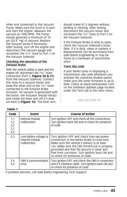
Code Event Course of Action
1,11,22,23,13,2
Internal modulemalfunction
Turn ignition OFF and check all the connections. Turn ignition back ON and re-check for presence of code.
2,3 Low battery voltage or internal modulemalfunction
Turn ignition OFF and check fuse-tap power connection to the Banks Brake (in fuse box). Make sure the vehicle’s battery is at least 12v. Make sure the CBC/SmartLock is properly grounded and that the ground is clean and free from corrosion. Turn ignition back ON and re-check for presence of code.
2,43,4
OBD II communication error
Turn ignition OFF and check the OBD II connection and it’s interface cable. Turn ignition back ON and re-check for presence of code.
If problem persists, call Gale Banks Engineering Tech Support.
Table 1

46 97055 v.8.0
This Page Intentionally Left Blank

97055 v.8.0 47
Figure 48- 2004-2005 Model Template Location #1
Figure 49- 2004-2005 Model Template Location #2
2004-2005Model Template
2004-2005Model Template

48 97055 v.8.0
This Page Intentionally Left Blank

97055 v.8.0 49
Figure 50- 2006-07 Model Template
Figure 51- 2006-07 Model Template
2006-07Model Template
2006-07Model Template

50 97055 v.8.0
Notes

97055 v.8.0 51
Notes

Gale Banks Engineering 546 Duggan Avenue • Azusa, CA 91702 (626) 969-9600 • Fax (626) 334-1743
Product Information & Sales: (888) 635-4565
bankspower.com