OWNER'S / OPERATOR'S TOMMY GATE MANUAL · Tommy Gate or an authorized distributor for assistance....
24
CAUTION x Safety Information x Warranty Information x Operator's Instructions x Maintenance Instructions x Parts List PLEASE KEEP IN VEHICLE and the Safety Compliance Certification Label located on the driver's door pillar. Limitations. These loading limitations are outlined in the Vehicle Owner's Manual Before installing or using this Lift Gate, please observe the Vehicle Loading ! CAUTION ! Made in America OWNER'S / OPERATOR'S MANUAL Railgate Series 1600 & 2000 Woodbine, Iowa DPN: 009900 Page 1 of 24 Rev 15 6-26-17 TOMMY GATE The original hydraulic lift n
-
Upload
truongkhuong -
Category
Documents
-
view
215 -
download
0
Transcript of OWNER'S / OPERATOR'S TOMMY GATE MANUAL · Tommy Gate or an authorized distributor for assistance....

CAUTION
Safety InformationWarranty InformationOperator's InstructionsMaintenance InstructionsParts List
PLEASE KEEP IN VEHICLE
and the Safety Compliance Certification Label located on the driver's door pillar.Limitations. These loading limitations are outlined in the Vehicle Owner's Manual Before installing or using this Lift Gate, please observe the Vehicle Loading !
CAUTION!
Made in America
OWNER'S / OPERATOR'SMANUAL
Railgate Series1600 & 2000
Woodbine, Iowa
DPN: 009900 Page 1 of 24 Rev 15 6-26-17
TOMMY GATEThe original
hydraulic lift
®

Contact Information
Repair Parts ListRepair Parts DrawingBottle Rack Repair Parts DrawingAluminum Cartstop Repair Parts DrawingRepair Parts Descriptions
WarrantyStandard WarrantyWarranty Claims Handling Procedure
Service Records
24
23
2221
1920
1817
Maintenance and Service
Electrical Wiring DiagramsStandard Fixed ControlOptional Pendant Control
Operator's InstructionsRailgate Terms and Method of OperationSelf Close Operator's InstructionsTorsion Spring Operator's InstructionsRetention Ramp Operator's Instructions
Safety DecalsLocation and DescriptionsDecal Replacement
IntroductionTo the Owner\Operator
TABLE OF CONTENTS
Trouble Shooting
3
16
15
1314
10 & 11
78 & 9
64 - 6
Page#
12
DPN: 009900 Page 2 of 24 Rev 15 6-26-17

It has been said that "the best safety device is an informed, careful operator." We ask youto be that kind of operator.
injury hazards. Obey all safety messages that follow this symbol to avoid
Read this manual completely before using your gate. Operate and maintain your gate safely
proper training of the personnel who operate, transport, maintain and store this equipment. It
our efforts to provide safe equipment can be wiped out by a single careless act of an operator.Safety is a primary concern in the design and manufacture of our products. Unfortunately,
This is the safety alert symbol. It is used to alert you to potential personal
maintenance and service information. Should you need repair or service information, contact
possible injury or death.
Tommy Gate or an authorized distributor for assistance.
TO THE OWNER\OPERATOR:
CAUTION indicates a potentially hazardous situation which, if not
avoided, could result in death or serious injury.
avoided, will result in death or serious injury.
is your responsibility to use good judgment in the operation of this equipment.
Accident prevention and safety are dependent upon the awareness, concern, prudence and
DANGER indicates an imminently hazardous situation which, if not
WARNING indicates a potentially hazardous situation which, if not
avoided, may result in minor or moderate injury.
as outlined in this manual. Be sure you read and understand all operating, safety,
CAUTION
WARNING
DANGER
avoided, may result in property damage.CAUTION indicates a potentially hazardous situation which, if not CAUTION
DPN: 009900 Page 3 of 24 Rev 15 6-26-17

TOMMY GATE CO.
TOMMY LIFT
WOODBINE MANUFACTURING CO.
WOODBINE, IOWA
(800) LIFTGATE
Decal No. 5Located on the inside of the main frame.
Positioned over the top of the pump & motor unit.Located on the driver side of upright.
DECAL LOCATIONS AND DESCRIPTIONS
Located on the passenger side platform lid end.Decal No. 4
DANGER
Keep away from
Located on the outside right-hand
Located on the control shield.
moving partsDecal No. 3
Decal No. 2
corner of the platform.
9555
SERIAL NUMBER
PART NUMBER
Locate and read all decals prior to operating gateREPLACE IF MISSING OR NOT READABLE
R
DPN: 009900 Page 4 of 24 Rev 15 6-26-17
Located on the passenger side upright.Decal No. 1
Platform opening and closing forces/weightswill vary if your vehicle is on an incline.
the liftgate.Stand clear of all moving parts when operating
WARNING
14254Do not add any extension to original platform.
WARNING
14253
CENTERLOAD
Tommy Gate does notrecommend that you ride on theplatform while operating theliftgate. However, if you mustride in order to safely move yourcargo, follow the safetyprecautions listed in the owner'smanual.
Center and secure load onplatform side to side and front toback.
Stand in a safe position awayfrom moving parts while theliftgate is in use.
14493
Read maintenance and serviceinformation.
Frequently check liftgatecomponents and safety devicesfor wear or damage and repair asnecessary.
Do not modify or disable safetyfeatures.
Do not try to lift or lower morethan the rated capacity of the lift.
Never allow children or anyuntrained person to operate thelift.
Do not show children or othershow to operate the lift.
When the lift is not in use, isunattended, or the vehicle ismoving, the platform should beclosed and latched with controlsecured.
WARNING
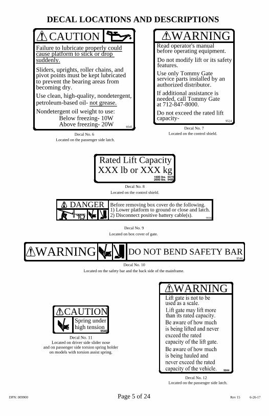
DECAL LOCATIONS AND DESCRIPTIONS
at 712-847-8000.
authorized distributor.If additional assistance isneeded, call Tommy Gate
Use only Tommy Gate
Do not modify lift or its safety
service parts installed by an
WARNINGRead operator's manualbefore operating equipment.
Do not exceed the rated lift
Decal No. 7Located on the control shield.
DO NOT BEND SAFETY BARWARNINGLocated on box cover of gate.
Decal No. 9
Decal No. 10Located on the safety bar and the back side of the mainframe.
suddenly.
Decal No. 6Located on the passenger side latch.
Use clean, high-quality, nondetergent,
Sliders, uprights, roller chains, and pivot points must be kept lubricatedto prevent the bearing areas from
petroleum-based oil- not grease.
Below freezing- 10WAbove freezing- 20W
Nondetergent oil weight to use:
becoming dry.
Decal No. 8
XXX lb or XXX kgRated Lift Capacity
Located on the control shield.
9545
capacity-
features.
cause platform to stick or drop Failure to lubricate properly could
CAUTION
9546
9524
WARNING
Decal No. 12
CAUTIONhigh tensionSpring under
Decal No. 11
and on passenger side torsion spring holderLocated on driver side slider nose
on models with torsion assist spring.
DANGER9556
2) Disconnect positive battery cable(s).1) Lower platform to ground or close and latch.Before removing box cover do the following.
DPN: 009900 Page 5 of 24 Rev 15 6-26-17
Located on the passenger side latch.

Allow to dry. To apply decal, peel off 1/2 of back. Hold decal squarely and apply to cleaned
sponge to smooth out bubbles.(The decal has a pressure-sensitive adhesive on the back.)
To replace decal, clear area of grease and dirt with non-flammable solvent and soap and water.
surface. Peel off remaining back and smooth in place. Gently rub decal with a damp rag or
NOTE: When ordering Decals, please have Decal Numbers available.
If the liftgate is going to be painted, you need to mask the decals before painting. Remove themask after painting so the decals can be read clearly.
DECAL REPLACEMENT
DECAL LOCATIONS AND DESCRIPTIONS
Refer to the Installation
Instructions for more cutting
details. 2928
CAUTIONMaximum outrail ground
clearance for this rail gate
is 21".
Cutting the outrail incorrectly
will result in damage to the
rail gate.
Refer to the Installation
Instructions for more cutting
details. 2929
CAUTIONMaximum outrail ground
clearance for this "Bed
Height" rail gate is 28".
Cutting the outrail incorrectly
will result in damage to the
rail gate.
Located on the inside of each uprightDecal No. 13
below the mainframe (ABOVE BED GATES ONLY). below the mainframe (BED HEIGHT GATES ONLY).Located on the inside of each upright
Decal No. 14
WARNINGPINCH POINT
WARNINGPINCH POINT
2987
Decal No. 15Located on smooth side of flipper
in the center. (RETENTION RAMP
Decal No. 16
When platform is open and the flipper is folded, located on rearmost surface of the main platform. One on passenger side and
3081
and one on driver side (RETENTION RAMP and RF GATES ONLY).
Located on smooth side of both ramps.Decal No.17
(RETENTION RAMP ONLY)
AND RF GATES ONLY).
Located on the safety bar in two places (ALL MODELS).
Located outside of upright, same side as control.Decal No. 18
11808
DPN: 009900 Page 6 of 24 Rev 15 6-26-17

DPN: 009900 Page 7 of 24 Rev 15 6-26-17
RAILGATE TERMS AND METHOD OF OPERATION
Figure 1: Railgate terms.
!Caution:
Never leave the truck with the platform on the ground, partially raised, or open.Never show children or unauthorized personnel how to operate the gate. To prevent children or unauthorized personnel from operating the lift, be sure the gate is in the stored position and both the driver's side and passenger's side latches are secured. Make sure the passenger's side latch padlock is installed and the control is deactivated before leaving the truck unattended.
Your Tommy Gate is connected to your vehicle battery. The vehicle battery powers a motor, coupled to ahydraulic pump. This motor and pump combination is called a power unit. Flow from the pump extends acylinder to provide tension to the lift chains that lift the gate platform. A check valve blocks return flowfrom the cylinder to the pump and a pressure relief valve prevents the gate from being overloaded. The gateplatform is lowered by gravity after the "lower" solenoid valve is activated and opened at the pump.
!Warning: Liftgate is not to be used as a scale. Liftgate may lift more than its rated capacity. Be aware of how much is being lifted and never exceed the rated capacity of the liftgate. Be aware of how much is being hauled and never exceed the rated capacity of the vehicle.
Two safety switches are mounted above the safety trip bar. These two switches interrupt power from the"raise" solenoid and direct the power to the "lower" solenoid valve if an obstruction raises the safety trip bar.
A "Low Voltage" condition exist when 7 Volts or less is present at the power unit. A low voltage conditionshould be corrected as soon as possible. In a "Low Voltage" situation, whether the gate actually raises orlowers depends on how low the voltage is.
Caution: Continuing to operate the the liftgate in the "Low Voltage" condition may result in failure of electrical components in the power unit.
The low voltage condition may be caused by a weak battery, loose or corroded connections, improper ground,or bad electrical cables. This condition may be corrected by just starting the vehicle or replacing the battery.
The terms used to describe parts of therailgate in this manual can be found in(Figure 1).
(Torsion Spring Models Only)TORSION SPRING
CONTROL
CYLINDER IN MAIN FRAME
LATCH
BEARING PADSSLIDERS WITH
MAIN FRAME
UPRIGHTS
DROP LID CHAIN
(Self-close Models Only)
SAFETY TRIP BAR
SELF-CLOSING ARM
BOX COVER
PLATFORM
LIGHTS
MAIN FRAME
LIFT CHAINS AND SPROCKETS IN
PUMP, MOTOR AND
(RF Gates Only)MAIN PLATFORM
PLATFORM FLIPPER(RF Gates Only)
TIE DOWN RINGS CONTROL SHIELD

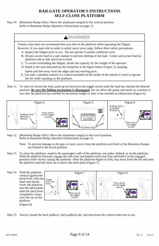
RAILGATE OPERATOR'S INSTRUCTIONSSELF-CLOSE PLATFORM
Be sure to stand to the side of the lift, not behind it when opening the platform.Clear away obstructions that could damage the platform while the load is being raised or lowered.Never show children or unauthorized personnel how to operate the railgate.
position. Check to make sure the folding arms have returned to the neutral position (Figure 4).Lower the platform slowly allowing the platform folding mechanism to unfold the platform to the horizontal
(Retention Ramp Only) Move the aluminum ramp(s) to the loading position.Refer to Retention Ramp Operator's Instructions on page 12.
hand, lower the platform approximately 4" by moving the control toggle switch to the down position
When the platform has traveled high enough to prevent the latch from re-engaging(approximately 1 inch),release the latch lever, grasp the platform and move the platform away from the latch plate.With the other
latch. With the other hand, raise the platform by moving the control toggle switch to the up positionUnlock and remove the latch padlock and pin. Use one hand to move the latch lever back to disengage the
Figure 2
Step 7.
Step 8.
the togglePress up on
switch
Step 5.
Step 6.
Step 3.Step 2.
Step 4.
Step 1.
Figure 3
Press downon the toggle
switch
Note: Railgate capacity depends on both the weight and location of the load. Capacity of the 1600 & 2000Series is based on a load at capacity located 28" back of the platform front (near truck).
Put heavier loads as close to the front of the platform as possible(near truck). Tie down rings are providedTo load and use the railgate, center the load on the platform side to side and front to back. Step 9.
DPN: 009900 Page 8 of 24 Rev 15 6-26-17
(Figure 2).
(Figure 3).
to help secure the load (Figure 5).
To turn the control power on, press the "POWER ON"hidden switch once, marked with white rings or circles(located below the Tommy Gate logo). You should seethe amber LED "POWER ON" light when the control isarmed. To disarm the control press the "POWER ON"hidden switch again. Terms used for the control areshown in (Figure 2).
To activate the control, press the "LIFTGATEACTIVATED" hidden switch twice within onesecond (located under the Tommy Gate logo). Youshould see the red "LIFTGATE ACTIVATED" lightwhen the control is activated. To lower the platform,push the control toggle switch down. To raise theplatform, push the control toggle switch up. When youremove pressure from the control toggle switch, theoperation will stop.
Figure 2: Control terms.
LIFTGATEACTIVATED
"RAISE/LOWER" TOGGLE SWITCH
ONPOWER
UP
DN
SWITCH - PRESS TWICE WITHIN ONE SECOND TO
SWITCH - PRESS ONCE TO
ACTIVATE TIMER
DISARMARM, PRESS AGAIN TO
"POWER ON" HIDDEN
"LIFTGATE ACTIVATED"
"POWER ON" AMBER LED-
RED LED - ENABLED WHEN
"LIFTGATE ACTIVATED" HIDDEN
ENABLED WHEN "ON"
"ON"
After you have activated the control by pressing the "LIFTGATE ACTIVATED" hidden switch twice withinone second(located under the Tommy Gate logo), you have approximately 5 minutes to use the gate. If thegate is not used for approximately 5 minutes, the "LIFTGATE ACTIVATED" timer deactivates the control.If the gate is used during the 5 minutes, the "LIFTGATE ACTIVATED" timer automatically resets for anadditional 5 minutes. To reactivate the timer, press the "LIFTGATE ACTIVATED" hidden button twicewithin one second.
Note: If your gate includes a pendant control, the operation of the pendant will be the same but the"LIFTGATE ACTIVATED" timer will be 90 seconds.
LIFTGATEACTIVATEDON
POWER
UP
DN
LIFTGATEACTIVATEDON
POWER
UP
DN
CENTERLOAD
Self-Closehand and slowly
Always install the latch padlock, latch padlock pin, and deactivate the control when not in use.Step 15.
over the ear on thecompletely closes until the latch lever into the latch plates lower the platform
platform
Arms
Press up onthe toggle
switch
on the togglePress down
switch
With the platform lowered, engage the self-close mechanism with your foot and hold it in the engagedTo close the platform, stand to the passenger's side of the platform, not under, behind, or on the platform.
position while slowly raising the platform. After the platform begins to fold, step away from the lift and raise
Step 14.
Step 13.
switchNeutral
the platform until the latch ear is above the latch plate (Figure 7).
latch lever with one vertical against theHold the platform
Engage
Figure 7
Figure 4
Return to Folding Arms on the toggle
Press down
Figure 5
the togglePress up on
Figure 8
switch
Figure 6Folding Arms
Positionin Neutral
RAILGATE OPERATOR'S INSTRUCTIONSSELF-CLOSE PLATFORM
Refer to Retention Ramp Operator's Instructions on page 12.(Retention Ramp Only) Move the aluminum ramp(s) to the vertical position.Step 10.
Refer to Retention Ramp Operator's Instructions on page 12.(Retention Ramp Only) Move the aluminum ramp(s) to the travel position.Step 12.
Note: To prevent damage to the gate or truck, never close the platform until both of the Retention Rampsare locked in the travel position.
DPN: 009900 Page 9 of 24 Rev 15 6-26-17
However, if you must ride in order to safely move your cargo, follow these safety precautions.Tommy Gate does not recommend that you ride on the platform while operating the liftgate.
C. To avoid overloading the liftgate, derate the capacity by the weight of the operator.
B. Always secure load in a safe manner to prevent shifting of the load. Center and secure load on
D. Stand in the area indicated by the footprints in the figure below (Figure 5), keeping
E. Use only a pendant control or a control mounted on the inside of the outrail or truck to operate
A. Inspect the liftgate prior to use. Do not operate if unsafe conditions exist.
the lift while standing on the platform.
hands and feet away from the edges and any moving parts.
WARNING
(Figure 8).
Step 11. To raise (or lower) the load, push up (or down) on the toggle switch until the load has reached the desired position. Be sure the folding mechanism is disengaged. Do not allow the pump and motor to continue to run after the platform has reached its maximum height or after it has reached an obstruction (Figure 6).
platform side to side and front to back.
Tie down ring
LIFTGATEACTIVATEDON
POWER
UP
DN
LIFTGATEACTIVATEDON
POWER
UP
DN
LIFTGATEACTIVATEDON
POWER
UP
DN
LIFTGATEACTIVATEDON
POWER
UP
DN

Step 5. Unlock and remove the latch padlock and pin. Use one hand to move the latch lever back to disengage the latch. With the other hand, raise the platform by moving the control toggle switch to the up position (Figure 10).
switch
Press up onthe toggle
Step 6. When the platform has traveled high enough to prevent the latch from re-engaging(approximately 1 inch), release the latch lever, grasp the platform and move the platform away from the latch plate. With the other hand, lower the platform approximately 4" by moving the control toggle switch to the down position (Figure 11).Step 7. Use both hands and unfold the platform to the horizontal position (Figure 12).
Figure 10
on the togglePress down
switch
Figure 11 Figure 12
RAILGATE OPERATOR'S INSTRUCTIONSTORSION SPRING PLATFORM
Step 1. Never show children or unauthorized personnel how to operate the railgate.
Step 3. Be sure to stand to the side of the lift, not behind it when opening the platform.Step 2. Clear away obstructions that could damage the platform while the load is being raised or lowered.
Step 9. (RF gates only) Open the folding extension (Figure 13).
Step 8. (RF gates only) position the platform at a comfortable height to open the folding extension (Figure 13).
Figure 13 (RF only)
Note: Grasp the platform as high as possible to reduce the required opening weight of the platform.
FoldingExtension
DPN: 009900 Page 10 of 24 Rev 15 6-26-17
To turn the control power on, press the "POWER ON"hidden switch once, marked with white rings or circles(located below the Tommy Gate logo). You should seethe amber LED "POWER ON" light when the control isarmed. To disarm the control press the "POWER ON"hidden switch again. Terms used for the control areshown in (Figure 2).
To activate the control, press the "LIFTGATEACTIVATED" hidden switch twice within onesecond (located under the Tommy Gate logo). Youshould see the red "LIFTGATE ACTIVATED" lightwhen the control is activated. To lower the platform,push the control toggle switch down. To raise theplatform, push the control toggle switch up. When youremove pressure from the control toggle switch, theoperation will stop.
Figure 2: Control terms.
LIFTGATEACTIVATED
"RAISE/LOWER" TOGGLE SWITCH
ONPOWER
UP
DN
SWITCH - PRESS TWICE WITHIN ONE SECOND TO
SWITCH - PRESS ONCE TO
ACTIVATE TIMER
DISARMARM, PRESS AGAIN TO
"POWER ON" HIDDEN
"LIFTGATE ACTIVATED"
"POWER ON" AMBER LED-
RED LED - ENABLED WHEN
"LIFTGATE ACTIVATED" HIDDEN
ENABLED WHEN "ON"
"ON"
After you have activated the control by pressing the "LIFTGATE ACTIVATED" hidden switch twice withinone second(located under the Tommy Gate logo), you have approximately 5 minutes to use the gate. If thegate is not used for approximately 5 minutes, the "LIFTGATE ACTIVATED" timer deactivates the control.If the gate is used during the 5 minutes, the "LIFTGATE ACTIVATED" timer automatically resets for anadditional 5 minutes. To reactivate the timer, press the "LIFTGATE ACTIVATED" hidden button twicewithin one second.
Note: If your gate includes a pendant control, the operation of the pendant will be the same but the"LIFTGATE ACTIVATED" timer will be 90 seconds.
LIFTGATEACTIVATEDON
POWER
UP
DN
LIFTGATEACTIVATEDON
POWER
UP
DN

FoldingExtension
Figure 17 (RF only)
Step 11. To load and use the railgate, center the load on the platform side to side and front to back. Put heavier loads as close to the front of the platform as possible(near truck). Tie down rings are provided to help secure the load (Figure 15).
Step 10. Lower the platform to the ground by pressing down on the toggle switch.
Figure 14
Press downon the toggleswitch
Figure 15
Step 12. To raise (or lower) the load, push up (or down) on the toggle switch until the load has reached the desired position. Do not allow the pump and motor to continue to run after the platform has reached its maximum height or after it has reached an obstruction (Figure 16).
Figure 16
switchthe togglePress up on
RAILGATE OPERATOR'S INSTRUCTIONSTORSION SPRING PLATFORM
Note: Railgate capacity depends on both the weight and location of the load. Capacity of the 1600 & 2000Series is based on a load at capacity located 28" back of the platform front (near truck).
DPN: 009900 Page 11 of 24 Rev 15 6-26-17
Note: The platform must be lowered 4" below bed height to keep the platform from coming in contact withthe mainframe, to prevent the platform ear from going over the latch lever, and reduce the platform closingeffort.
Step 15. To close the platform, stand to the passenger's side of the platform, not under, behind, or on the platform. Position the platform approximately 4" below bed height. Use both hands to fold the platform to the vertical position (Figure 18).
Step 13. (RF gates only) Position the platform at a comfortable height to close the folding extension (Figure 17).Step 14. (RF gates only) Close the folding extension (Figure 17).
Step 17. Always install the latch padlock, latch padlock pin, and deactivate the control when not in use.
Step 16. Hold the platform vertical against the latch lever with one hand and slowly lower the platform into the latch plates until the latch lever completely closes over the ear on the platform (Figure 19).
switch
BED HEIGHTPOSITION PLATFORMBELOW BED HEIGHT
Figure 18
on the togglePress down
Figure 19
CENTERLOAD
However, if you must ride in order to safely move your cargo, follow these safety precautions.Tommy Gate does not recommend that you ride on the platform while operating the liftgate.
C. To avoid overloading the liftgate, derate the capacity by the weight of the operator.
B. Always secure load in a safe manner to prevent shifting of the load. Center and secure load on
D. Stand in the area indicated by the footprints in the figure below (Figure 15), keeping
E. Use only a pendant control or a control mounted on the inside of the outrail or truck to operate
A. Inspect the liftgate prior to use. Do not operate if unsafe conditions exist.
the lift while standing on the platform.
hands and feet away from the edges and any moving parts.
WARNING
platform side to side and front to back.
Tie down ring
LIFTGATEACTIVATEDON
POWER
UP
DN
LIFTGATEACTIVATEDON
POWER
UP
DN
LIFTGATEACTIVATEDON
POWER
UP
DN

Slide ramp away from gate to Rotate ramp to position desired.
Push ramp down to lockPull ramp up to unlock Rotate ramp to desired position
Push ramp down to lock in loading positionLift ramp up to unlock from loading poistion
unlock from the travel position.
from the vertical position in vertical position
RETENTION RAMP OPERATOR'S INSTRUCTIONS
Platform and ramp bothin the travel position.
Platform open with rampin the travel position.
Platform open with rampin the vertical position. in the loading position.
Platform open with ramp
Retention Ramp locked in various positions.
lock in the travel position.Slide ramp toward gate to
Rotate the ramp to desired position.
Travel position
Vertical Position
Loading Position
DPN: 009900 Page 12 of 24 Rev 15 6-26-17

DPN: 009900 Page 13 of 24 Rev 15 6-26-17
CONTROL OPERATION
IMPORTANT
PLEASE READ AND FOLLOW ALLDIRECTIONS BEFORE PROCEEDING
"BAT" terminal
IMPORTANT
"AUX" terminal
Low Profile Control - RailgateELECTRICAL WIRING DIAGRAM
FIREWALL THROUGH MOUNTING HOLESATTACH TO VEHICLE FENDER OR
VEHICLEBATTERY
+POS.
-NEG.
AWG #4GROUND CABLE
"LOWER" SOLENOIDVALVE
PUMP AND MOTORCOMMON GROUND
PUMP/MOTOR
MAIN POWER CABLE AWG #4
BUTT CONNECTORHEAT SHRINK
OR BROWN - LOWERYELLOW, RED, BLACK,
BROWN - LOWER
GREEN
SWITCHES1 = COM.
WHITE3 = N.O.2 = N.C.
23
123
1
BLACK - GND.
GREEN - RAISE
BROWN - LOWER
BLACK - NOT A GROUND +12VDC SUPPLYFOR CONTROL
RED -
SYSTEM
AWG #18 WIRES
MAIN POWER CABLE AWG #4
SWITCH - PRESS TWICE WITHIN ONE SECOND TOACTIVATE TIMER
"POWER ON" HIDDEN SWITCH - PRESS ONCE TO
"LIFTGATE ACTIVATED" HIDDEN
"LIFTGATE ACTIVATED"
ENABLED WHEN "ON"
RED LED - ENABLED WHEN
"POWER ON" AMBER LED-
ARM, PRESS AGAIN TO
"ON"TOGGLE SWITCH"RAISE/LOWER"
MASTER DISCONNECTCIRCUIT BREAKER AND
150 AMP MANUAL RESET
"RAISE" SOLENOIDMOTOR
CONTACTOR
MAIN POWER CABLE AWG #4
DISARM
LIFTGATEACTIVATEDON
POWER
UP
DN
LIFTGATEACTIVATEDON
POWER
UP
DN
NOTE !!! IF GATES ARE NOT WIREDIN ACCORDANCE WITH THIS DIAGRAMYOUR WARRANTY WILL BE VOID.
WELDING NOTE !!! DISCONNECT ALL BATTERY CABLES.ALWAYS DISCONNECT THE GROUND CABLE FIRST. ATTACH THEWELDING GROUND TO THE TRUCK RATHER THAN THE LIFTGATE.
TOMMY GATEThe original
hydraulic lift
®

WIRE
BLACK
GREEN
COLOR
BROWN
NO WIRE
NO WIRE
NO WIRE
WIRE INSERTION SIDE
CONNECTOR BACK VIEW
BROWN - LOWER
BLINKING AMBER LED
TOGGLE SWITCH
CONTROL OPERATION
VOLTAGE CONDITIONINDICATES LOW
"RAISE/LOWER"
HEAT SHRINKBUTT CONNECTOR
TMARM, PRESS AGAIN TO
DNGD
A
RED
BROWN - LOWER
"POWER ON" AMBER LED-
RED LED - ENABLED WHEN
ENABLED WHEN "ON"
"LIFTGATE ACTIVATED"
"LIFTGATE ACTIVATED" HIDDEN
SWITCH - PRESS ONCE TO "POWER ON" HIDDEN
ACTIVATE TIMERWITHIN ONE SECOND TOSWITCH - PRESS TWICE
UP
"ON"
3SAFETY BAR
SWITCHES1 2
3
2 = N.C.3 = N.O.
WHITE
1 = COM.
GREEN
1
BLACK - GND.
GREEN - RAISE
2
TMBROWN
COLE HERSEE
POSITION
S
LT
RT
SOCKET END
NO WIRELT
REDGD
AWG #18 WIRES
PENDANTFEMALE
PLUG
IMPORTANT
NEG.-
PLEASE READ AND FOLLOW ALLDIRECTIONS BEFORE PROCEEDING
YELLOW, RED, BLACK,OR BROWN - LOWER
AWG #4GROUND CABLE
"BAT" terminal
BLACK - NOT A GROUND
PUMP AND MOTOR
"LOWER" SOLENOID
PUMP/MOTOR
MAIN POWER CABLE AWG #4
COMMON GROUND
VALVE
CIRCUIT BREAKER ANDMASTER DISCONNECT
MAIN POWER CABLE
VEHICLEBATTERY
POS.+
AWG #4
150 AMP MANUAL RESET
IMPORTANT
AWG #4 MAIN POWER CABLE
RED -
FOR CONTROLSYSTEM
+12VDC SUPPLY
"AUX" terminal
Optional Pendant Control - RailgateELECTRICAL WIRING DIAGRAM
A
RTGREEN
BLACKS
DN
UP
CONTACTORMOTOR
"RAISE" SOLENOID
FIREWALL THROUGH MOUNTING HOLESATTACH TO VEHICLE FENDER OR
DISARM
DPN: 009900 Page 14 of 24 Rev 15 6-26-17
Note: This control has a 90 second "Liftgate Activated" timer.
NOTE !!! IF GATES ARE NOT WIREDIN ACCORDANCE WITH THIS DIAGRAMYOUR WARRANTY WILL BE VOID.
WELDING NOTE !!! DISCONNECT ALL BATTERY CABLES.ALWAYS DISCONNECT THE GROUND CABLE FIRST. ATTACH THEWELDING GROUND TO THE TRUCK RATHER THAN THE LIFTGATE.
TOMMY GATEThe original
hydraulic lift
®
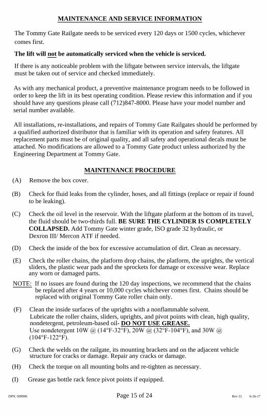
replaced with original Tommy Gate roller chain only.be replaced after 4 years or 10,000 cycles whichever comes first. Chains should be
NOTE: If no issues are found during the 120 day inspections, we recommend that the chains
MAINTENANCE PROCEDURE
nondetergent, petroleum-based oil-Use nondetergent 10W @ (14°F-32°F), 20W @ (32°F-104°F), and 30W @
Lubricate the roller chains, sliders, uprights, and pivot points with clean, high quality,
Check the oil level in the reservoir. With the liftgate platform at the bottom of its travel,the fluid should be two-thirds full. BE SURE THE CYLINDER IS COMPLETELYCOLLAPSED. Add Tommy Gate winter grade, ISO grade 32 hydraulic, orDexron III/ Mercon ATF if needed.
(H) Check the torque on all mounting bolts and re-tighten as necessary.
structure for cracks or damage. Repair any cracks or damage.
sliders, the plastic wear pads and the sprockets for damage or excessive wear. Replace
(G) Check the welds on the railgate, its mounting brackets and on the adjacent vehicle
Check the inside of the box for excessive accumulation of dirt. Clean as necessary.
(E) Check the roller chains, the platform drop chains, the platform, the uprights, the vertical
Check for fluid leaks from the cylinder, hoses, and all fittings (replace or repair if found
(F) Clean the inside surfaces of the uprights with a nonflammable solvent.
All installations, re-installations, and repairs of Tommy Gate Railgates should be performed bya qualified authorized distributor that is familiar with its operation and safety features. Allreplacement parts must be of original quality, and all safety and operational decals must beattached. No modifications are allowed to a Tommy Gate product unless authorized by theEngineering Department at Tommy Gate.
As with any mechanical product, a preventive maintenance program needs to be followed inorder to keep the lift in its best operating condition. Please review this information and if youshould have any questions please call (712)847-8000. Please have your model number andserial number available.
If there is any noticeable problem with the liftgate between service intervals, the liftgatemust be taken out of service and checked immediately.
The lift will not be automatically serviced when the vehicle is serviced.
MAINTENANCE AND SERVICE INFORMATION
The Tommy Gate Railgate needs to be serviced every 120 days or 1500 cycles, whichever
(C)
(104°F-122°F).
any worn or damaged parts.
(D)
to be leaking).
(A) Remove the box cover.
(B)
DO NOT USE GREASE.
comes first.
DPN: 009900 Page 15 of 24 Rev 15 6-26-17
(I) Grease gas bottle rack fence pivot points if equipped.

b.) Safety switch bent or stuck open.a.) Safety trip bar damaged.
d.) Platform drop chains improperly adjusted.
side of platform.c.) Load has been put off to one bottom of uprights.b.) Installer has left a burr ata.) Lift chains need to be adjusted.
ACTIVATED" LED light on.b.) Poor electrical connections.
ON" LED or red "LIFTGATE
release solenoid.damaged or non-working
activated - No amber "POWER
d.) If control working properly, c.) Sliders sticking in uprights.
a.) Control not armed and
a.) Cold, thick, oil.b.) Sliders sticking in uprights.
adjusted.j.) Lifting roller chains improperly
release solenoid open.f.) Safety bar switch bent- Holding
b.) Oil level low
a.) Poor electrical connection.b.) Battery charge is low.c.) Release valve stuck partially
open or dirty.d.) Release valve needs
replacement.e.) "Raise" solenoid not working.
i.) Overloaded liftgate.
a.) Worn pump, motor or coupling.partially open.
e.) Down solenoid sticking d.) Cylinder seals worn or damaged.
a.) Hoses or fittings leaking.
c.) Check valve damaged.b.) Check valve stuck or dirty.
h.) Vent plug not installed or dirty.g.) Oil level low.
a.) Low voltage condition.b.) Poor grounds or connections.c.) Power connected or reconnected
since last use.
POSSIBLE CAUSETROUBLE SHOOTING - 1600 & 2000 RAILGATE SERIES
c.) Faulty control.
e.) Faulty control.disengaged.
d.) Circuit breaker tripped or
light is blinking.b.) Control not activated properly.
a.) "POWER ON" amber LED
c.) Polarity is reversed.b.) Poor electrical connection.a.) Control not armed properly.
smoothly.
trying to raise.10.) Gate lowers when
cold weather.
9.) Gate does not lower
8.) Lift will not lower.
slowly, especially in7.) Lift lowers very
slowly with load or no
6.) Pump or motor noisy.
5.) Lift settles down
load.
working properly.raises slowly - control
4.) Lift will not raise or
"POWER ON" LED.3.) Blinking amber
LED light does not
LED light does not
"LIFTGATE 2.) Lift will not operate -
ACTIVATED" red
"POWER ON" amber1.) Lift will not operate -
come on.
PROBLEM
come on.
i.) Remove some material or weight.
both driver's and passenger's side.
b.) Check switches for free movement up and down.a.) Straighten or replace safety bar.
d.) Adjust platform drop chains.c.) Center load on the platform.
b.) Raise and close platform, grind or file off burr from outrail.
a.) Adjust lift chains so platform is level with top of mainframe on
"LIFTGATE ACTIVATED" LED light should come on.b.) Check and clean or repair all electrical connections.
within one second (located under the Tommy Gate logo). The redNow press the hidden "LIFTGATE ACTIVATED" switch twice switch). The amber "POWER ON" LED light should come on.
d.) Contact Tommy Gate or distributor.
circles (located between the Tommy Gate logo and the toggle a.) Press the "POWER ON" hidden switch, marked with white rings or
c.) Clean sliders and lubricate with nondetergent oil. Apply downward
b.) Clean Sliders and Lubricate with nondetergent oil.
a.) Check oil type. Add winter grade Tommy Gate hydraulic orDexron III/Mercon ATF.
j.) Adjust Lifting roller chains.
hydraulic, or Dexron III/Mercon ATF.b.) Check oil and add ISO grade 32, Tommy Gate winter gradea.) Contact Tommy Gate or distributor.
a.) Tighten or replace.
c,d,e.) Contact Tommy Gate or distributor for repair or replacement.to flush out valve.
b.) Raise and lower lift several times
load on platform.
d,e,f.) Contact Tommy Gate or distributor.
c.) Raise platform completely and continue to run pump for
a.) Check power and ground cables and all connections.b.) Recharge or replace battery.
hydraulic,or Dexron III/Mercon ATF.
at factory. It must be replaced by the metal vented plug.h.) Check vent plug on pump tank. A red shipping plug is installed
g.) Check oil and add ISO grade 32, Tommy Gate winter grade
battery, then recharge or replace battery, if required.a.) Check and clean or repair all electrical connections. Load test
b.) Repair, replace, clean as necessary.c.) Normal, press bullseye once to activate solid "POWER ON" amber
d.) Check for short, then manually engage circuit breaker.
"LIFTGATE ACTIVATED" LED light should come on.one second (located under the Tommy Gate logo). The red
b.) Press the "LIFTGATE ACTIVATED" hidden switch twice within
a.) Low voltage condition. Check and repair or replace all cables and
the Tommy Gate logo and the toggle switch).
c.) Switch positive and negative cables.
hidden switch, marked with white rings or circles (located betweena.) Turn the power on at the control by pressing the "POWER ON"
b.) Check and repair or replace all cables and connections.
c.) Replace control.
5 seconds.
LED.
e.) Replace Control.
connections.
REMEDIES
DPN: 009900 Page 16 of 24 Rev 15 6-26-17
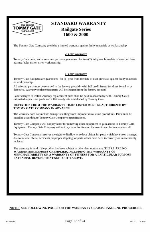
NOTE: SEE FOLLOWING PAGE FOR THE WARRANTY CLAIMS HANDLING PROCEDURE.
Tommy Gate Company reserves the right to disallow or reduce claims for parts which have been damaged
Tommy Gate Company will not pay labor for removing other equipment to gain access to Tommy Gate
The warranty does not include damage resulting from improper installation procedures. Parts must be
estimated repair time guide and a flat hourly rate established by Tommy Gate.
Tommy Gate Railgates are guaranteed for (1) year from the date of user purchase against faulty materials
Tommy Gate pump and motor unit parts are guaranteed for two (2) full years from date of user purchase
MERCHANTABILITY OR A WARRANTY OF FITNESS FOR A PARTICULAR PURPOSE
The warranty is void if the product has been subject to other than normal use. THERE ARE NOWARRANTIES, EXPRESS OR IMPLIED, INCLUDING THE WARRANTY OF
DEVIATION FROM THE WARRANTY TIMES LISTED MUST BE AUTHORIZED BY
STANDARD WARRANTY
due to misuse, abuse, accidents, improper shipping; or parts which have been incorrectly or unnecessarily
Equipment. Tommy Gate Company will not pay labor for time on the road to and from a service call.
Labor charges to install warranty replacement parts shall be paid in accordance with Tommy Gate's
defective. Warranty replacement parts will be shipped from the factory prepaid.All affected parts must be returned to the factory prepaid - with full credit issued for those found to be
The Tommy Gate Company provides a limited warranty against faulty materials or workmanship.
EXTENDING BEYOND THAT SET FORTH ABOVE.
replaced.
Railgate Series1600 & 2000
against faulty materials or workmanship.
TOMMY GATE COMPANY IN ADVANCE.
installed according to Tommy Gate Company's specifications.
or workmanship.
2-Year Warranty
1-Year Warranty
DPN: 009900 Page 17 of 24 Rev 15 6-26-17
TOMMY GATEThe original
hydraulic lift
®

(outlined in step 5 above) as they apply to the requirements of Tommy Gate Warranty. Claim reimbursement after
3. If the product or parts are to be repaired, the authorized distributor will receive a WARRANTY
WARRANTY CLAIMS HANDLING PROCEDURE
authorized distributor will receive instructions on how to proceed. A decision will be made to either repair2. If it is determined that the condition is potentially covered by Tommy Gate Company's warranty, the
contact Tommy Gate Company's Warranty Department to discuss the problem and its correction.1. Before any expense is incurred, but after the problem has been diagnosed, the authorized distributor should
The following procedures are required when an authorized distributor submits a warranty claim for a defective
Any warranty claims submitted without a WARRANTY REQUESTNUMBER or RETURN GOODS AUTHORIZATION NUMBER andthe necessary information will be denied.
c. Must be clearly marked with the RETURN GOODS AUTHORIZATION NUMBER on the outside of the package.
a. Tommy Gate Company WARRANTY REQUEST and/or RETURN GOODS AUTHORIZATION NUMBER.
Tommy Gate Company, in which case the authorized distributor will receive a RETURN GOODSAUTHORIZATION NUMBER. Under no circumstances are parts to be returned without a RETURNGOODS AUTHORIZATION NUMBER.
for inspection by a representative, in which case the authorized distributor will receive a WARRANTYREQUEST NUMBER, or the authorized distributor will be asked to return the product for inspection to
4. If the product or parts are to be replaced, the authorized distributor will be instructed to either hold the parts
acceptance is governed by those allowances previously agreed upon between Tommy Gate Company and
Warranty claim acceptance or rejection is based solely upon defective part inspection and a review of the claim date
Warranty claims must be submitted by the Authorized Distributor on behalf of their customer as part of their
b. Must be returned "freight prepaid" to Tommy Gate Company's location.a. Must be packaged for each individual warranty return. No multiple warranty claims in the same box.
i. Action taken, cost involved, complete with work orders and parts expense invoices.
d. Tommy Gate part number involved and a description of the apparent problem or defect.
5. After the repair or replacement work is completed, the authorized distributor will submit the claim to
f. Person responsible for warranty work (contact).
the Authorized Distributor (as outlined in Steps 1-4 above).
6. If defective parts are to be returned to Tommy Gate Company they:
h. Lift gate owner's name, address, and phone number.g. Distributor from whom lift gate was purchased.
customer assistance.
Tommy Gate part:
Tommy Gate Company with the following information.
or replace the product or part in question.
e. Authorized distributor performing warranty work.
b. Tommy Gate model number.c. Tommy Gate serial number.
REQUEST NUMBER.
DPN: 009900 Page 18 of 24 Rev 15 6-26-17
TOMMY GATEThe original
hydraulic lift
®

1600 AND 2000 RAILGATE SERIESREPAIR PARTS DRAWING
FOR MODELS 73, 79, 85, 89 & 95(WITH INTERNAL TIMED ELECTRIC TOGGLE CONTROL)
43
6
182
56
1
42
6859
53, 5455
565
7
8
844
42
417
8
82
84
6
83
8
67
38
10
46
15
10
8 47
11 33
12
13
14
21
40
24
25
2630
37
3520
27
233266
31
17
3
39
15
10
11
4 34
28
10
48
2
70
49
18
5251
DPN: 009900 Page 19 of 24 Rev 15 6-26-17
100
19

93
87
91
188
9085
89
1600 AND 2000 RAILGATE SERIESBOTTLE RACK REPAIR PARTS DRAWING
FOR MODELS 73, 79, 85, 89 & 95(WITH INTERNAL TIMED ELECTRIC TOGGLE CONTROL)
8990
85
86
93
92
DPN: 009900 Page 20 of 24 Rev 15 6-26-17

DPN: 009900 Page 21 of 24 Rev 15 6-26-17
75
76
1600 AND 2000 RAILGATE SERIESALUMINUM CARTSTOP REPAIR PARTS DRAWING
FOR MODELS 73, 79, 85, 89 & 95(WITH INTERNAL TIMED ELECTRIC TOGGLE CONTROL)
77
75
78
79
7677
94 9995

Cylinder Repair Kit67
Pump & Motor20
Note:The item number is not the part number. Please have the model number and serial numberavailable before calling for repair parts.
Steel Cylinder Elbow
19 Tooth Sprocket25 Tooth Sprocket
4ga. 2 Wire Electric Cable
33 Cylinder Shaft
39
35
3837
34
Hydraulic Hose
Cylinder ClampCylinder Barrel
30
2726
3132
28
25242321
Copper Lug
Lee Check Valve
CylinderCylinder Pin
Flow Control
Motor-Only
Vent PlugTank
Bottle Rack Horizontal Tube
Platform Triangle Deadman
Left Cartstop Assembly
Left Cartstop LatchCartstop Spring AssemblyRight Cartstop Assembly
Bottle Rack Fence-RightBottle Rack Lynch PinBottle Rack Pivot Plate
Bottle Rack TaperBottle Rack Fence-Left
Platform Stop Block-RF Only
Bottle Rack ChainSquare Torsion Spring
Right Cartstop Latch
89
9293
9091 Pivot Pin
79
868788
8485
76
7877
68
75
Cloth Chain Cover
13 Tooth Sprocket
License Plate LightBox Cover w/Lights
License Plate Mount KitRailgate Latch Spring
DESCRIPTION
1600 AND 2000 RAILGATE SERIESREPAIR PARTS LIST
FOR MODELS 73, 79, 85, 89 & 95(WITH INTERNAL TIMED ELECTRIC TOGGLE CONTROL)
8
1819
1715
10
1211
1413
Latch Lever
Timed Control
Raise SolenoidLatch Plate
Red LightClear Light
ITEM#
2
567
34
1Platform Chains
Safety SwitchSliderBearing Pad Set
Platform
Upright Cap-Bed Height OnlyUpright Cap-Above Bed Only150 Amp Manual Reset Circuit BreakerRoller Chain Cover- Above Bed onlyAdjustment Screw, Clevis & Pin
Roller Chain Attachment FittingRoller Chain-Passenger's Side
Self-Close RollerSelf-Close Arm BushingExtension Spring
Self-Close Rod and LinkageSelf-Close Arm-LeftSelf-Close Arm-Right
Release SolenoidSafety Trip Bar
Hinge Tube
DESCRIPTION
47
54
59
6665
5556
51
5352
4948
41
4446
42
ITEM#
70 Latch Padlock and Pin
90 Degree Pump Elbow40
8382
Platform Latch-RF OnlyPlatform Gear Kit-RF Only
DPN: 009900 Page 22 of 24 Rev 15 6-26-17
9594 Cartstop Torsion Springs
Cartstop Latch Kit99 Cartstop Hinge Kit
43 Roller Chain- Driver's Side 100 CTC Mounting Bracket and Shield Kit

Reminders: Service liftgate according to page 15.
Date of Service Services Performed
SERVICE RECORD
Installed By:
Date of Purchase:LIFTGATE INFORMATION
Model Number:
Serial Number:
DPN: 009900 Page 23 of 24 Rev 15 6-26-17

TM
America's First Namein Liftgates
DPN: 009900 Page 24 of 24 Rev 15 6-26-17
www.tommygate.com
Manufacturing Plant:83 Bus Brown Drive
Woodbine, Iowa 51579FAX (712) 647-2417
Corporate Offices:33717 N. Scottsdale Rd. Ste 120
Scottsdale, AZ 85266FAX (602) 955-3902
(712) 847-8000
TOMMY GATEThe original
hydraulic lift
®