
Original Series 500-1600 LB Capacity - Tommy Gate · DPN: 009115 ... Original Series 500-1600 LB...
20
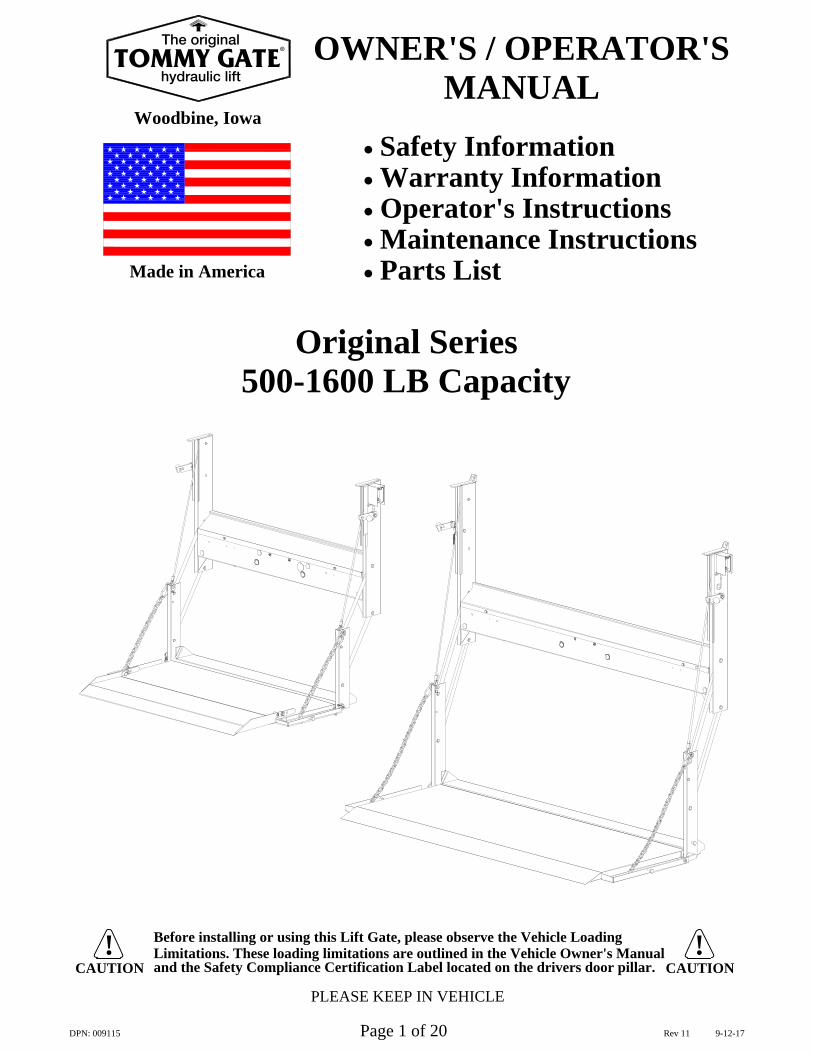
and the Safety Compliance Certification Label located on the drivers door pillar. Limitations. These loading limitations are outlined in the Vehicle Owner's Manual Before installing or using this Lift Gate, please observe the Vehicle Loading ! PLEASE KEEP IN VEHICLE CAUTION ! CAUTION Made in America Woodbine, Iowa x Safety Information x Warranty Information x Operator's Instructions x Maintenance Instructions x Parts List OWNER'S / OPERATOR'S MANUAL DPN: 009115 Page 1 of 20 Rev 11 9-12-17 Original Series 500-1600 LB Capacity TOMMY GATE The original hydraulic lift n
Transcript of Original Series 500-1600 LB Capacity - Tommy Gate · DPN: 009115 ... Original Series 500-1600 LB...
and the Safety Compliance Certification Label located on the drivers door pillar.Limitations. These loading limitations are outlined in the Vehicle Owner's Manual Before installing or using this Lift Gate, please observe the Vehicle Loading !
PLEASE KEEP IN VEHICLE
CAUTION!
CAUTION
Made in America
Woodbine, Iowa
Safety InformationWarranty InformationOperator's InstructionsMaintenance InstructionsParts List
OWNER'S / OPERATOR'SMANUAL
DPN: 009115 Page 1 of 20 Rev 11 9-12-17
Original Series500-1600 LB Capacity
TOMMY GATEThe original
hydraulic lift
®
Trouble Shooting
Repair Parts List534, 1034, 1036, and 1040 Repair Parts Drawing1050-1650 Repair Parts Drawing
Repair Parts Descriptions
WarrantyStandard WarrantyWarranty Claims Handling Procedure
Contact Information
Service Records
20
19
18
1617
14-1514
Maintenance and Service
Electrical Wiring DiagramsStandard Fixed ControlOptional Pendant Control
Operator's InstructionsOriginal Series Terms and Method of OperationOperator's Instructions
Drop Away Feature
Safety DecalsLocation and DescriptionsDecal Replacement
TABLE OF CONTENTS
IntroductionTo the Owner\Operator 3
11
12
13
10
4 - 5
67 & 8
5
Page#
9
DPN: 009115 Page 2 of 20 Rev 11 9-12-17
TOMMY GATEThe original
hydraulic lift
®
maintenance and service information. Should you need repair or service information, contact
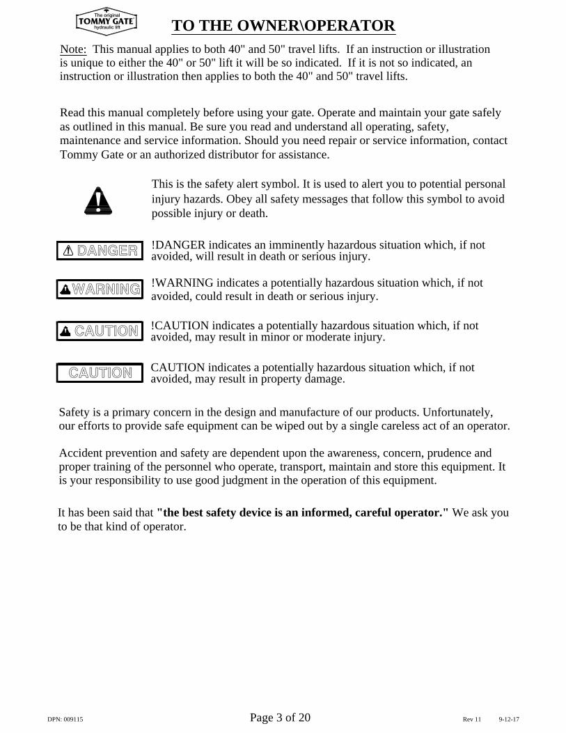
This is the safety alert symbol. It is used to alert you to potential personal
Safety is a primary concern in the design and manufacture of our products. Unfortunately,
Read this manual completely before using your gate. Operate and maintain your gate safely
injury hazards. Obey all safety messages that follow this symbol to avoid
proper training of the personnel who operate, transport, maintain and store this equipment. It
It has been said that "the best safety device is an informed, careful operator." We ask youto be that kind of operator.
our efforts to provide safe equipment can be wiped out by a single careless act of an operator.
is your responsibility to use good judgment in the operation of this equipment.
as outlined in this manual. Be sure you read and understand all operating, safety,
avoided, may result in minor or moderate injury.
!WARNING indicates a potentially hazardous situation which, if not
!DANGER indicates an imminently hazardous situation which, if not avoided, will result in death or serious injury.
avoided, could result in death or serious injury.
!CAUTION indicates a potentially hazardous situation which, if not
Tommy Gate or an authorized distributor for assistance.
possible injury or death.
Accident prevention and safety are dependent upon the awareness, concern, prudence and
WARNING
CAUTION
DANGER
TO THE OWNER\OPERATORNote: This manual applies to both 40" and 50" travel lifts. If an instruction or illustrationis unique to either the 40" or 50" lift it will be so indicated. If it is not so indicated, aninstruction or illustration then applies to both the 40" and 50" travel lifts.
avoided, may result in property damage.CAUTION indicates a potentially hazardous situation which, if not CAUTION
DPN: 009115 Page 3 of 20 Rev 11 9-12-17
TOMMY GATEThe original
hydraulic lift
®
DECAL LOCATIONS AND DESCRIPTIONS
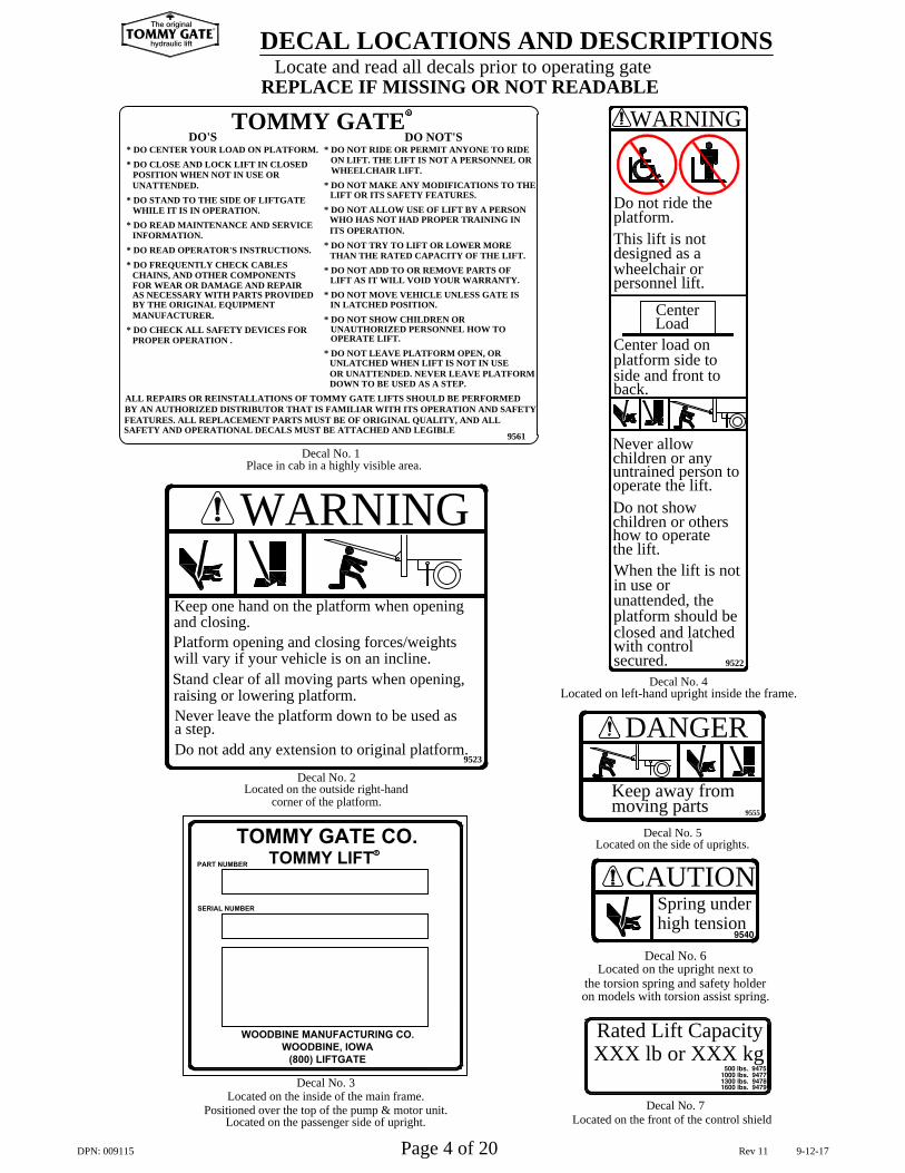
Decal No. 7Located on the front of the control shield
XXX lb or XXX kgRated Lift Capacity
CAUTIONhigh tensionSpring under
Decal No. 6
the torsion spring and safety holderLocated on the upright next to
on models with torsion assist spring.
Located on left-hand upright inside the frame.
Located on the side of uprights.
DANGER
Keep away frommoving parts
Decal No. 5
platform.
Center Load
platform side to side and front to
Center load on
This lift is not
wheelchair or designed as a
personnel lift.
Do not ride the
WARNING
the lift.
in use or
secured.
untrained person to
platform should be
Decal No. 4
closed and latchedwith control
When the lift is not
unattended, the
how to operatechildren or othersDo not show operate the lift.
Never allow children or any
will vary if your vehicle is on an incline.
TOMMY GATE CO.
WOODBINE MANUFACTURING CO.
WOODBINE, IOWA
(800) LIFTGATE
Located on the inside of the main frame.Positioned over the top of the pump & motor unit.
Located on the passenger side of upright.
Located on the outside right-hand
Never leave the platform down to be used as
Do not add any extension to original platform.
Stand clear of all moving parts when opening,
SERIAL NUMBER
Decal No. 3
raising or lowering platform.
PART NUMBER
a step.
TOMMY LIFT
corner of the platform.
R
Decal No. 29523
UNATTENDED.
PROPER OPERATION .
MANUFACTURER.
INFORMATION.
SAFETY AND OPERATIONAL DECALS MUST BE ATTACHED AND LEGIBLEFEATURES. ALL REPLACEMENT PARTS MUST BE OF ORIGINAL QUALITY, AND ALLBY AN AUTHORIZED DISTRIBUTOR THAT IS FAMILIAR WITH ITS OPERATION AND SAFETYALL REPAIRS OR REINSTALLATIONS OF TOMMY GATE LIFTS SHOULD BE PERFORMED
* DO CHECK ALL SAFETY DEVICES FOR
BY THE ORIGINAL EQUIPMENT
* DO FREQUENTLY CHECK CABLES
FOR WEAR OR DAMAGE AND REPAIRCHAINS, AND OTHER COMPONENTS
AS NECESSARY WITH PARTS PROVIDED
POSITION WHEN NOT IN USE OR
WHILE IT IS IN OPERATION.* DO STAND TO THE SIDE OF LIFTGATE
* DO READ OPERATOR'S INSTRUCTIONS.
* DO READ MAINTENANCE AND SERVICE
* DO CLOSE AND LOCK LIFT IN CLOSED* DO CENTER YOUR LOAD ON PLATFORM.
WHEELCHAIR LIFT.* DO NOT MAKE ANY MODIFICATIONS TO THE
LIFT OR ITS SAFETY FEATURES.
ITS OPERATION.
THAN THE RATED CAPACITY OF THE LIFT.
IN LATCHED POSITION.* DO NOT SHOW CHILDREN OR
OR UNATTENDED. NEVER LEAVE PLATFORMUNLATCHED WHEN LIFT IS NOT IN USE
* DO NOT LEAVE PLATFORM OPEN, OR
* DO NOT MOVE VEHICLE UNLESS GATE IS
UNAUTHORIZED PERSONNEL HOW TO
LIFT AS IT WILL VOID YOUR WARRANTY.* DO NOT ADD TO OR REMOVE PARTS OF
DOWN TO BE USED AS A STEP.
* DO NOT TRY TO LIFT OR LOWER MORE
* DO NOT ALLOW USE OF LIFT BY A PERSONWHO HAS NOT HAD PROPER TRAINING IN
Place in cab in a highly visible area.
Platform opening and closing forces/weights
Keep one hand on the platform when opening
WARNING
and closing.
Decal No. 1
OPERATE LIFT.
9561
back.
Locate and read all decals prior to operating gate
* DO NOT RIDE OR PERMIT ANYONE TO RIDEON LIFT. THE LIFT IS NOT A PERSONNEL OR
REPLACE IF MISSING OR NOT READABLE
TOMMY GATEDO'S
R
DO NOT'S
9522
9555
DPN: 009115 Page 4 of 20 Rev 11 9-12-17
TOMMY GATEThe original
hydraulic lift
®
remaining back and smooth in place. Gently rub decal with a damp rag or sponge to smooth out bubbles.
To replace decal, clear area of grease and dirt with non-flammable solvent and soap and water. Allow to
If the liftgate is going to be painted, you need to mask the decals before painting. Remove the mask afterpainting so the decals can be read clearly.
dry. To apply decal, peel off 1/2 of back. Hold decal squarely and apply to cleaned surface. Peel off
(The decal has a pressure-sensitive adhesive on the back.)
NOTE: When ordering Decals, please have Decal Numbers available.DECAL REPLACEMENT
WARNING
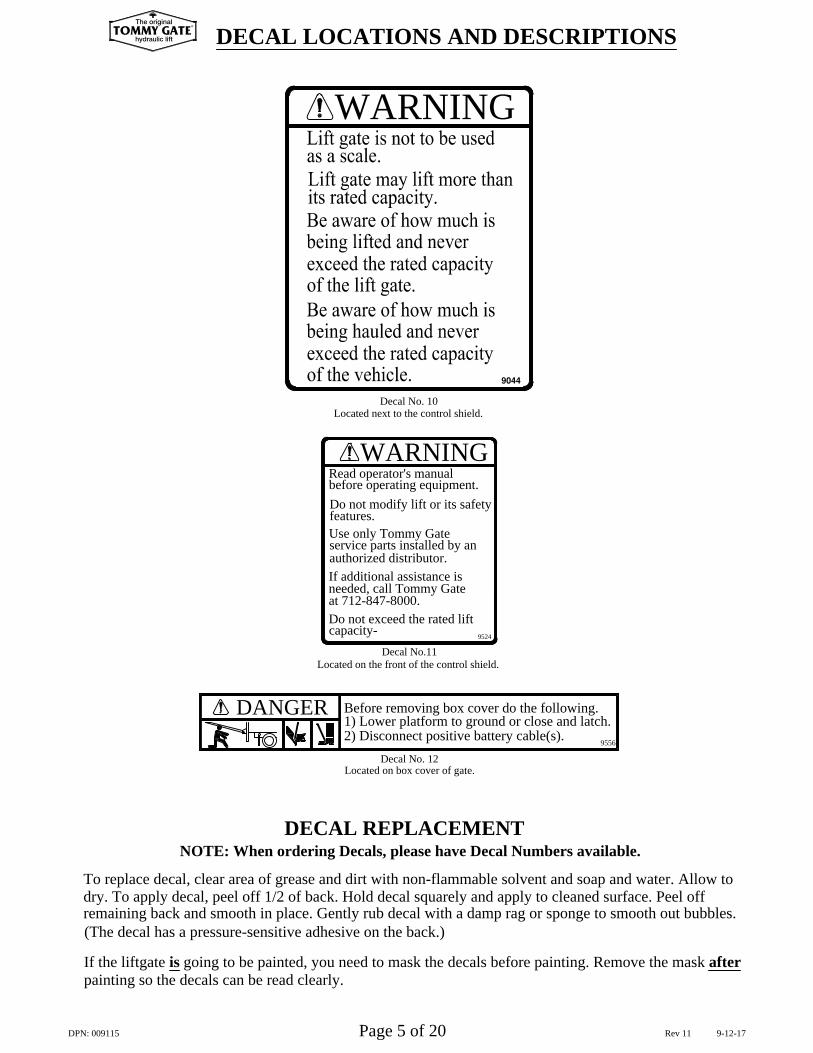
DECAL LOCATIONS AND DESCRIPTIONS
Located next to the control shield.Decal No. 10
If additional assistance is
at 712-847-8000.needed, call Tommy Gate
Do not exceed the rated lift
Located on the front of the control shield.
capacity-Decal No.11
9524
authorized distributor.
Use only Tommy Gate
Do not modify lift or its safety
service parts installed by an
WARNINGRead operator's manualbefore operating equipment.
features.
DPN: 009115 Page 5 of 20 Rev 11 9-12-17
DANGER
Located on box cover of gate.
9556
Decal No. 12
2) Disconnect positive battery cable(s).1) Lower platform to ground or close and latch.Before removing box cover do the following.
TOMMY GATEThe original
hydraulic lift
®
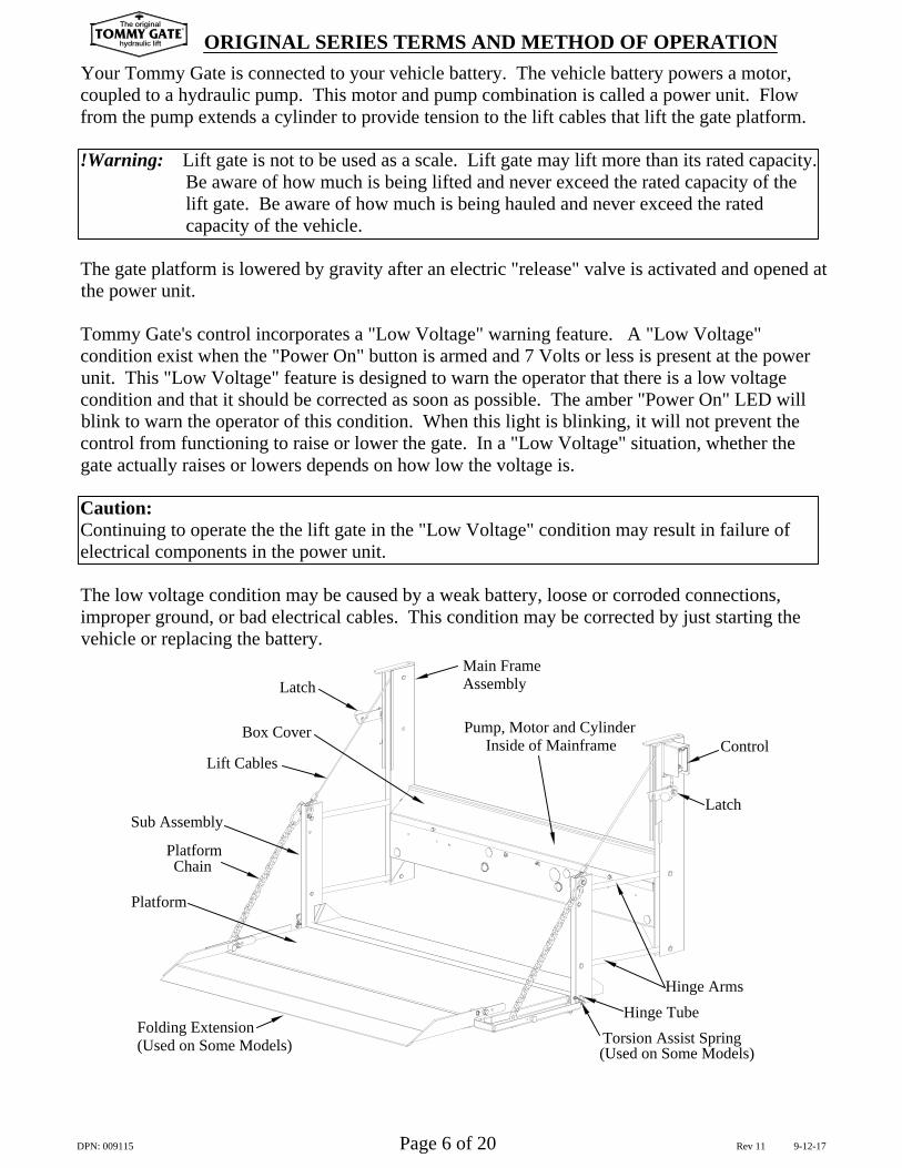
Your Tommy Gate is connected to your vehicle battery. The vehicle battery powers a motor,coupled to a hydraulic pump. This motor and pump combination is called a power unit. Flowfrom the pump extends a cylinder to provide tension to the lift cables that lift the gate platform.
!Warning: Lift gate is not to be used as a scale. Lift gate may lift more than its rated capacity. Be aware of how much is being lifted and never exceed the rated capacity of the lift gate. Be aware of how much is being hauled and never exceed the rated capacity of the vehicle.
The gate platform is lowered by gravity after an electric "release" valve is activated and opened atthe power unit.
Tommy Gate's control incorporates a "Low Voltage" warning feature. A "Low Voltage"condition exist when the "Power On" button is armed and 7 Volts or less is present at the powerunit. This "Low Voltage" feature is designed to warn the operator that there is a low voltagecondition and that it should be corrected as soon as possible. The amber "Power On" LED willblink to warn the operator of this condition. When this light is blinking, it will not prevent thecontrol from functioning to raise or lower the gate. In a "Low Voltage" situation, whether thegate actually raises or lowers depends on how low the voltage is.
Caution:Continuing to operate the the lift gate in the "Low Voltage" condition may result in failure ofelectrical components in the power unit.
The low voltage condition may be caused by a weak battery, loose or corroded connections,improper ground, or bad electrical cables. This condition may be corrected by just starting thevehicle or replacing the battery.
ORIGINAL SERIES TERMS AND METHOD OF OPERATION
Hinge Arms
Inside of Mainframe
Hinge TubeTorsion Assist Spring(Used on Some Models)
Platform
Sub Assembly
Chain
Folding Extension(Used on Some Models)
Platform
Box Cover
Lift Cables
Pump, Motor and Cylinder
AssemblyMain Frame
Control
Latch
Latch
DPN: 009115 Page 6 of 20 Rev 11 9-12-17
TOMMY GATEThe original
hydraulic lift
®
PlatformLid End
Latch
Padlock
ORIGINAL SERIES OPERATOR'S INSTRUCTIONS!Caution:
Never leave the truck with the platform on the ground, partially raised, or open.Never show children or unauthorized personnel how to operate the gate. To prevent children or unauthorized personnel from operating the lift, be sure the gate is in the stored position and both the driver's side and passenger's side latches are secured. Make sure the passenger's side latch padlock is installed and the control is deactivated before leaving the truck unattended.
!Warning: The Tommy Gate is an industrial product for material handling only and is not to be used as a personnel or wheelchair lift. Do not ride on the platform and always stand clear of the platform when opening, raising or lowering.
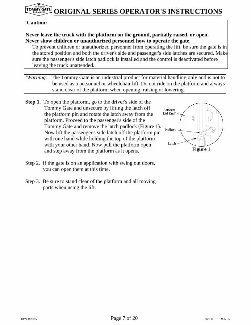
Step 1. To open the platform, go to the driver's side of the Tommy Gate and unsecure by lifting the latch off the platform pin and rotate the latch away from the platform. Proceed to the passenger's side of the Tommy Gate and remove the latch padlock (Figure 1). Now lift the passenger's side latch off the platform pin with one hand while holding the top of the platform with your other hand. Now pull the platform open and step away from the platform as it opens.
Step 2. If the gate is on an application with swing out doors, you can open them at this time.
Step 3. Be sure to stand clear of the platform and all moving parts when using the lift.
Figure 1
DPN: 009115 Page 7 of 20 Rev 11 9-12-17
TOMMY GATEThe original
hydraulic lift
®
ORIGINAL SERIES OPERATOR'S INSTRUCTIONS
Step 6. To lower the platform, stand to the side clear of the platform and all moving parts, then push the toggle switch down. When you remove pressure from the toggle switch, the operation will stop.
Step 7. To load and use the Tommy Gate, center the load on the platform side to side and front to back. Put heavier loads as close to the front of the platform (near truck) as possible.
Step 8. To raise platform, stand off to the side, well clear of the platform and all moving parts. Push up on the toggle switch until the platform has reached the desired position. When you remove pressure from the toggle switch, the operation will stop.
Caution: Do not allow the pump and motor to continue to run after the platform has reached it's maximum height or after it has reached an obstruction.
Step 9. When the platform is raised to the level of the vehicle's floor and the load is removed from the platform, close the platform and folding extension (if so equipped) by hand. The latch on the passenger's side will secure itself. Go to the driver's side and lift the latch and hook it onto the pin of the platform. Install the padlock (Figure 1).
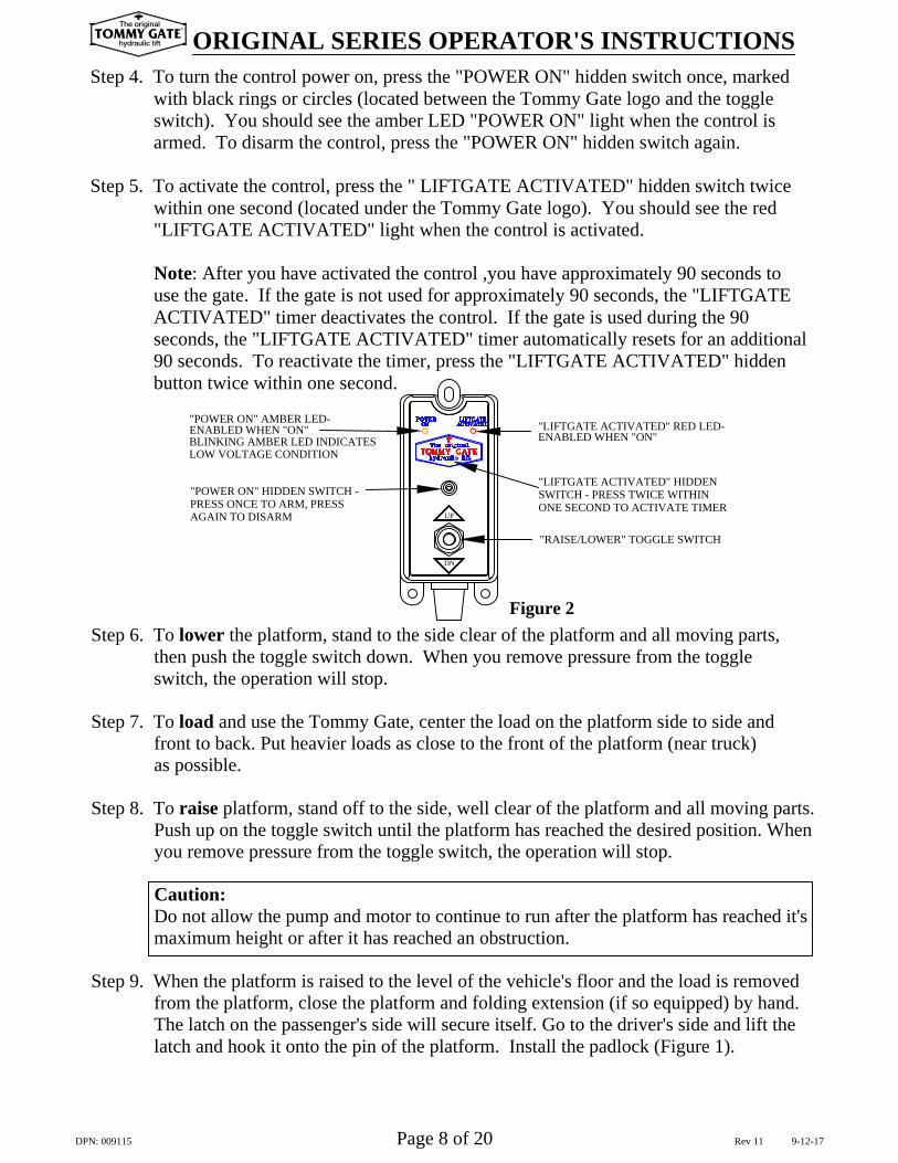
"RAISE/LOWER" TOGGLE SWITCH
ONE SECOND TO ACTIVATE TIMER
"LIFTGATE ACTIVATED" HIDDEN
"LIFTGATE ACTIVATED" RED LED-
"POWER ON" HIDDEN SWITCH - PRESS ONCE TO ARM, PRESSAGAIN TO DISARM UP
DN
SWITCH - PRESS TWICE WITHIN
LOW VOLTAGE CONDITION
ENABLED WHEN "ON"BLINKING AMBER LED INDICATES
"POWER ON" AMBER LED-ENABLED WHEN "ON"
Figure 2
Step 4. To turn the control power on, press the "POWER ON" hidden switch once, marked with black rings or circles (located between the Tommy Gate logo and the toggle switch). You should see the amber LED "POWER ON" light when the control is armed. To disarm the control, press the "POWER ON" hidden switch again.
Step 5. To activate the control, press the " LIFTGATE ACTIVATED" hidden switch twice within one second (located under the Tommy Gate logo). You should see the red "LIFTGATE ACTIVATED" light when the control is activated.
Note: After you have activated the control ,you have approximately 90 seconds to use the gate. If the gate is not used for approximately 90 seconds, the "LIFTGATE ACTIVATED" timer deactivates the control. If the gate is used during the 90 seconds, the "LIFTGATE ACTIVATED" timer automatically resets for an additional 90 seconds. To reactivate the timer, press the "LIFTGATE ACTIVATED" hidden button twice within one second.
DPN: 009115 Page 8 of 20 Rev 11 9-12-17
TOMMY GATEThe original
hydraulic lift
®
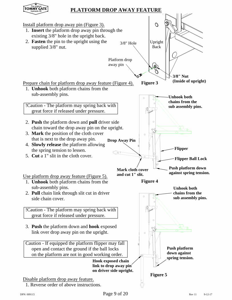
PLATFORM DROP AWAY FEATURE
Use platform drop away feature (Figure 5). 1. Unhook both platform chains from the sub-assembly pins. 2. Pull chain link through slit cut in driver side chain cover.
!Caution - The platform may spring back with great force if released under pressure.
3. Push the platform down and hook exposed link over drop away pin on the upright.
Caution - If equipped the platform flipper may fall open and contact the ground if the ball locks on the platform are not in good working order.
Prepare chain for platform drop away feature (Figure 4). 1. Unhook both platform chains from the sub-assembly pins.
!Caution - The platform may spring back with great force if released under pressure.
2. Push the platform down and pull driver side chain toward the drop away pin on the upright. 3. Mark the position of the cloth cover that is next to the drop away pin. 4. Slowly release the platform allowing the spring tension to lessen. 5. Cut a 1" slit in the cloth cover.
Unhook bothchains from thesub assembly pins.
Mark cloth coverand cut 1" slit.
Push platform downagainst spring tension.
Disable platform drop away feature. 1. Reverse order of above instructions.
Figure 4
Drop Away Pin
Flipper Ball Lock
Flipper
Unhook bothchains from thesub assembly pins.
Push platformdown againstspring tension.
Figure 5
Hook exposed chainlink to drop away pinon driver side upright.
DPN: 009115 Page 9 of 20 Rev 11 9-12-17
TOMMY GATEThe original
hydraulic lift
®
Install platform drop away pin (Figure 3). 1. Insert the platform drop away pin through the existing 3/8" hole in the upright back. 2. Fasten the pin to the upright using the supplied 3/8" nut.
Platform dropaway pin
3/8" Hole UprightBack
3/8" Nut(Inside of upright)Figure 3
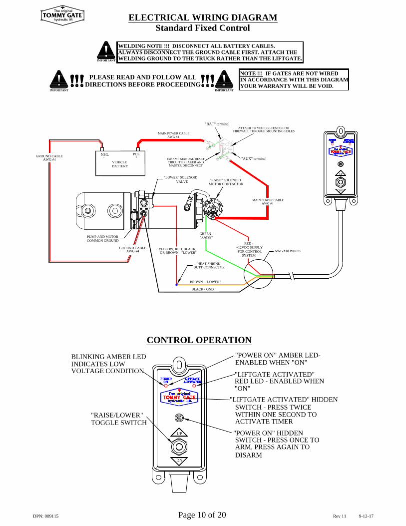
"RAISE/LOWER"
INDICATES LOWVOLTAGE CONDITION
BLINKING AMBER LED
TOGGLE SWITCH
CONTROL OPERATION
"LIFTGATE ACTIVATED" HIDDEN
"POWER ON" HIDDEN
DN
UP
"LIFTGATE ACTIVATED"
SWITCH - PRESS TWICE WITHIN ONE SECOND TO
RED LED - ENABLED WHEN
DISARM
SWITCH - PRESS ONCE TO ARM, PRESS AGAIN TO
ACTIVATE TIMER
"ON"
ENABLED WHEN "ON""POWER ON" AMBER LED-
IMPORTANT
PLEASE READ AND FOLLOW ALLDIRECTIONS BEFORE PROCEEDING
IMPORTANT
WELDING NOTE !!! DISCONNECT ALL BATTERY CABLES.ALWAYS DISCONNECT THE GROUND CABLE FIRST. ATTACH THEWELDING GROUND TO THE TRUCK RATHER THAN THE LIFTGATE.
IMPORTANT
NOTE !!! IF GATES ARE NOT WIREDIN ACCORDANCE WITH THIS DIAGRAMYOUR WARRANTY WILL BE VOID.
ELECTRICAL WIRING DIAGRAMStandard Fixed Control
FIREWALL THROUGH MOUNTING HOLESATTACH TO VEHICLE FENDER OR
"AUX" terminal
"BAT" terminal
DN
UP
NEG.-
POS.
BATTERYVEHICLE
+
COMMON GROUNDPUMP AND MOTOR
GROUND CABLEAWG #4
GROUND CABLEAWG #4
AWG #4 MAIN POWER CABLE
AWG #4 MAIN POWER CABLE
CIRCUIT BREAKER AND150 AMP MANUAL RESET
MASTER DISCONNECT
"LOWER" SOLENOIDVALVE
YELLOW, RED, BLACK,OR BROWN - "LOWER"
"RAISE" SOLENOIDMOTOR CONTACTOR
GREEN - "RAISE"
AWG #18 WIRES
BLACK - GND.
BROWN - "LOWER"
HEAT SHRINKBUTT CONNECTOR
+12VDC SUPPLYFOR CONTROL
SYSTEM
RED -
DPN: 009115 Page 10 of 20 Rev 11 9-12-17
TOMMY GATEThe original
hydraulic lift
®
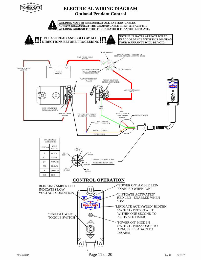
SOCKET ENDCOLE HERSEE
BLACK
NO WIRE
BROWN
NO WIRE
GREEN
COLORWIRE
INDICATES LOWVOLTAGE CONDITION
BLINKING AMBER LED
"RAISE/LOWER" TOGGLE SWITCH
RT
A
GD RED
TM
LT
POSITION
S
DISARMDN
"LIFTGATE ACTIVATED" HIDDEN
CONTROL OPERATION
UP
GREEN
NO WIRE
NO WIRELT
REDGD
TMBROWN
WIRE INSERTION SIDE
CONNECTOR BACK VIEW
RT
A
BLACKS
"LIFTGATE ACTIVATED"
ENABLED WHEN "ON"
RED LED - ENABLED WHEN
"POWER ON" AMBER LED-
SWITCH - PRESS TWICE WITHIN ONE SECOND TO
"POWER ON" HIDDEN SWITCH - PRESS ONCE TO ARM, PRESS AGAIN TO
ACTIVATE TIMER
"ON"
IMPORTANT
PLEASE READ AND FOLLOW ALLDIRECTIONS BEFORE PROCEEDING
IMPORTANT
WELDING NOTE !!! DISCONNECT ALL BATTERY CABLES.ALWAYS DISCONNECT THE GROUND CABLE FIRST. ATTACH THEWELDING GROUND TO THE TRUCK RATHER THAN THE LIFTGATE.
IMPORTANT
DN
UP
NOTE !!! IF GATES ARE NOT WIREDIN ACCORDANCE WITH THIS DIAGRAMYOUR WARRANTY WILL BE VOID.
ELECTRICAL WIRING DIAGRAMOptional Pendant Control
FIREWALL THROUGH MOUNTING HOLESATTACH TO VEHICLE FENDER OR
"AUX" terminal
"BAT" terminal
NEG.-
POS.
BATTERYVEHICLE
+
COMMON GROUNDPUMP AND MOTOR
GROUND CABLEAWG #4
GROUND CABLEAWG #4
AWG #4 MAIN POWER CABLE
AWG #4 MAIN POWER CABLE
CIRCUIT BREAKER AND150 AMP MANUAL RESET
MASTER DISCONNECT
"LOWER" SOLENOIDVALVE
OR BROWN - "LOWER"
"RAISE" SOLENOIDMOTOR CONTACTOR
AWG #18 WIRES
BLACK - GND.
BROWN - "LOWER"
HEAT SHRINKBUTT CONNECTOR
GREEN - "RAISE"
+12VDC SUPPLYFOR CONTROL
SYSTEM
RED -YELLOW, RED, BLACK,
DPN: 009115 Page 11 of 20 Rev 11 9-12-17
TOMMY GATEThe original
hydraulic lift
®
MAINTENANCE AND SERVICE INFORMATION
(O) Check for proper operation of the control.
(L) Replace or clean safety decals so they are legible.
(K) Check electrical cables for wear or damaged insulation. Check all electrical connections. (clean or
(I) If needed, adjust platform latches which are designed to hold the liftgate in a properly stored position.
(H) Replace any worn or missing parts before the liftgate is put back into service.
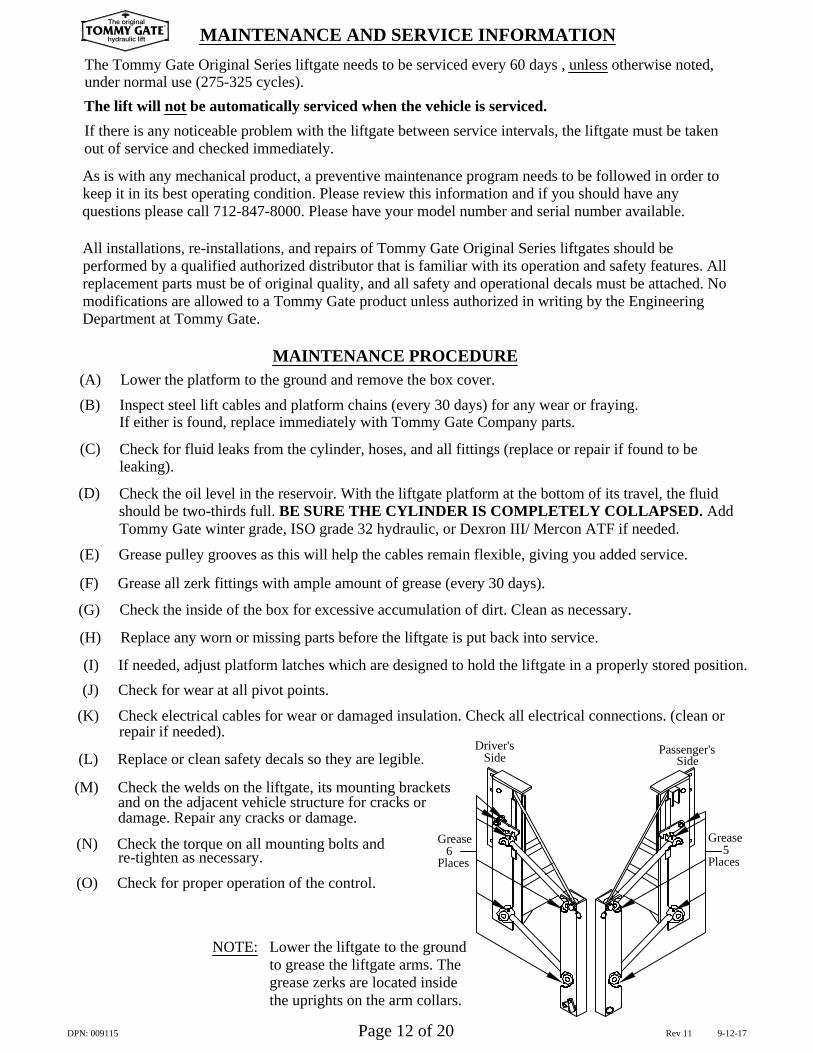
(F) Grease all zerk fittings with ample amount of grease (every 30 days).
(E) Grease pulley grooves as this will help the cables remain flexible, giving you added service.
(B) Inspect steel lift cables and platform chains (every 30 days) for any wear or fraying.
NOTE: Lower the liftgate to the groundto grease the liftgate arms. The grease zerks are located inside the uprights on the arm collars.
MAINTENANCE PROCEDURE
Check the oil level in the reservoir. With the liftgate platform at the bottom of its travel, the fluidshould be two-thirds full. BE SURE THE CYLINDER IS COMPLETELY COLLAPSED. AddTommy Gate winter grade, ISO grade 32 hydraulic, or Dexron III/ Mercon ATF if needed.
(N) Check the torque on all mounting bolts and
and on the adjacent vehicle structure for cracks or(M) Check the welds on the liftgate, its mounting brackets
Check the inside of the box for excessive accumulation of dirt. Clean as necessary.
Check for fluid leaks from the cylinder, hoses, and all fittings (replace or repair if found to be
All installations, re-installations, and repairs of Tommy Gate Original Series liftgates should beperformed by a qualified authorized distributor that is familiar with its operation and safety features. Allreplacement parts must be of original quality, and all safety and operational decals must be attached. Nomodifications are allowed to a Tommy Gate product unless authorized in writing by the EngineeringDepartment at Tommy Gate.
As is with any mechanical product, a preventive maintenance program needs to be followed in order tokeep it in its best operating condition. Please review this information and if you should have anyquestions please call 712-847-8000. Please have your model number and serial number available.
If there is any noticeable problem with the liftgate between service intervals, the liftgate must be takenout of service and checked immediately.
The lift will not be automatically serviced when the vehicle is serviced.
The Tommy Gate Original Series liftgate needs to be serviced every 60 days , unless otherwise noted,
re-tighten as necessary.
damage. Repair any cracks or damage.
repair if needed).
(J) Check for wear at all pivot points.
(G)
If either is found, replace immediately with Tommy Gate Company parts.
leaking).
(A) Lower the platform to the ground and remove the box cover.
(D)
(C)
under normal use (275-325 cycles).
Driver's
Grease
Places6
SidePassenger's
Grease
Places
Side
5
DPN: 009115 Page 12 of 20 Rev 11 9-12-17
TOMMY GATEThe original
hydraulic lift
®
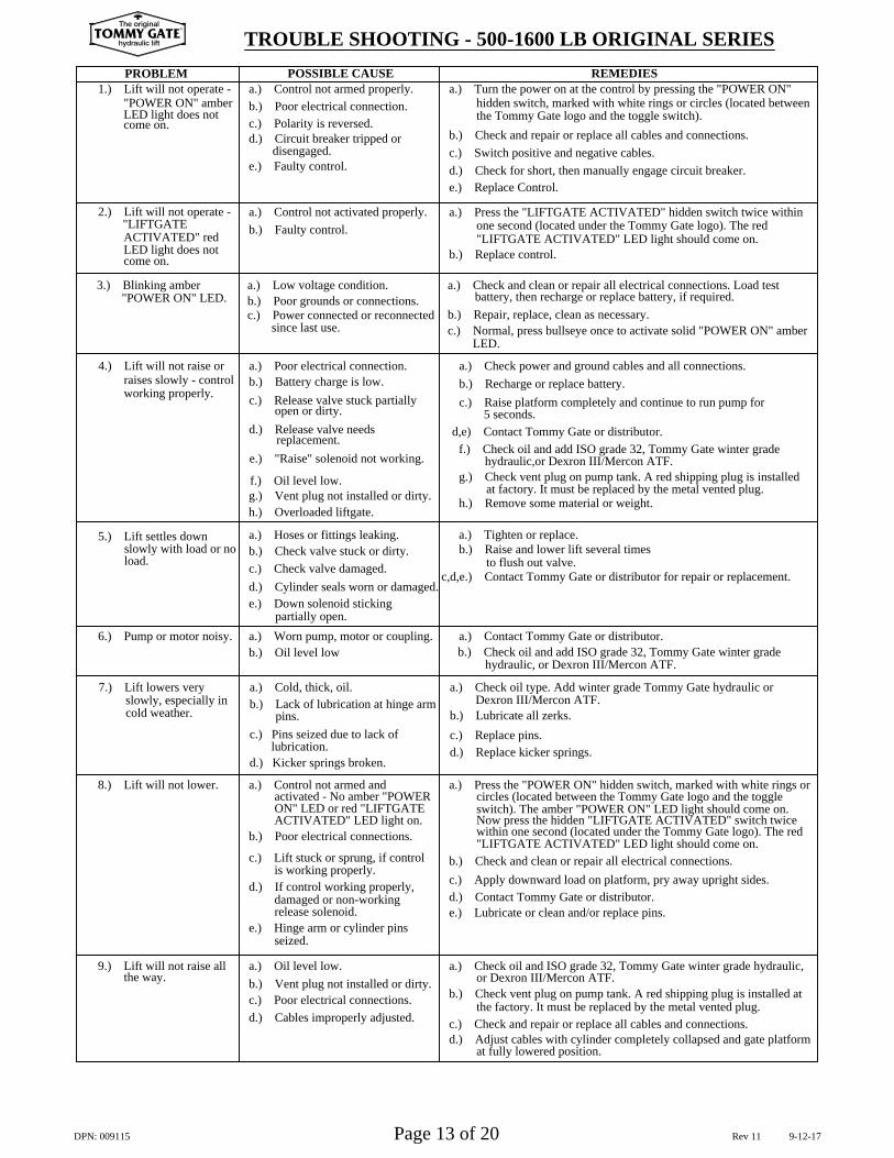
TROUBLE SHOOTING - 500-1600 LB ORIGINAL SERIES
a.) Oil level low.b.) Vent plug not installed or dirty.c.) Poor electrical connections.d.) Cables improperly adjusted.
e.) Hinge arm or cylinder pins
is working properly.
d.) Kicker springs broken.lubrication.
c.) Pins seized due to lack of
ACTIVATED" LED light on.b.) Poor electrical connections.
ON" LED or red "LIFTGATE
release solenoid.damaged or non-working
activated - No amber "POWER
d.) If control working properly,
c.) Lift stuck or sprung, if control
a.) Control not armed and
a.) Cold, thick, oil.b.) Lack of lubrication at hinge arm
b.) Oil level low
a.) Poor electrical connection.b.) Battery charge is low.c.) Release valve stuck partially
open or dirty.d.) Release valve needs
replacement.e.) "Raise" solenoid not working.
h.) Overloaded liftgate.
a.) Worn pump, motor or coupling.partially open.
e.) Down solenoid sticking d.) Cylinder seals worn or damaged.
a.) Hoses or fittings leaking.
c.) Check valve damaged.b.) Check valve stuck or dirty.
g.) Vent plug not installed or dirty.f.) Oil level low.
a.) Low voltage condition.b.) Poor grounds or connections.c.) Power connected or reconnected
since last use.
POSSIBLE CAUSE
b.) Faulty control.
e.) Faulty control.disengaged.
d.) Circuit breaker tripped or
a.) Control not activated properly.
c.) Polarity is reversed.b.) Poor electrical connection.a.) Control not armed properly.
9.) Lift will not raise all the way.
8.) Lift will not lower.
seized.
cold weather.slowly, especially in
7.) Lift lowers very
slowly with load or no
6.) Pump or motor noisy.
5.) Lift settles down
load.
pins.
working properly.raises slowly - control
4.) Lift will not raise or
"POWER ON" LED.3.) Blinking amber
LED light does not
LED light does not
"LIFTGATE 2.) Lift will not operate -
ACTIVATED" red
"POWER ON" amber1.) Lift will not operate -
come on.
PROBLEM
come on.
h.) Remove some material or weight.
at fully lowered position.
the factory. It must be replaced by the metal vented plug.
d.) Adjust cables with cylinder completely collapsed and gate platform
a.) Check oil and ISO grade 32, Tommy Gate winter grade hydraulic, or Dexron III/Mercon ATF.
b.) Check vent plug on pump tank. A red shipping plug is installed at
c.) Check and repair or replace all cables and connections.
e.) Lubricate or clean and/or replace pins.
d.) Replace kicker springs.
"LIFTGATE ACTIVATED" LED light should come on.b.) Check and clean or repair all electrical connections.
within one second (located under the Tommy Gate logo). The redNow press the hidden "LIFTGATE ACTIVATED" switch twice switch). The amber "POWER ON" LED light should come on.
d.) Contact Tommy Gate or distributor.
circles (located between the Tommy Gate logo and the toggle a.) Press the "POWER ON" hidden switch, marked with white rings or
c.) Apply downward load on platform, pry away upright sides.
b.) Lubricate all zerks.
a.) Check oil type. Add winter grade Tommy Gate hydraulic orDexron III/Mercon ATF.
hydraulic, or Dexron III/Mercon ATF.b.) Check oil and add ISO grade 32, Tommy Gate winter gradea.) Contact Tommy Gate or distributor.
a.) Tighten or replace.
c,d,e.) Contact Tommy Gate or distributor for repair or replacement.to flush out valve.
b.) Raise and lower lift several times
c.) Replace pins.
d,e) Contact Tommy Gate or distributor.
c.) Raise platform completely and continue to run pump for
a.) Check power and ground cables and all connections.b.) Recharge or replace battery.
hydraulic,or Dexron III/Mercon ATF.
at factory. It must be replaced by the metal vented plug.g.) Check vent plug on pump tank. A red shipping plug is installed
f.) Check oil and add ISO grade 32, Tommy Gate winter grade
battery, then recharge or replace battery, if required.a.) Check and clean or repair all electrical connections. Load test
b.) Repair, replace, clean as necessary.c.) Normal, press bullseye once to activate solid "POWER ON" amber
d.) Check for short, then manually engage circuit breaker.
"LIFTGATE ACTIVATED" LED light should come on.one second (located under the Tommy Gate logo). The red
a.) Press the "LIFTGATE ACTIVATED" hidden switch twice within
the Tommy Gate logo and the toggle switch).
c.) Switch positive and negative cables.
hidden switch, marked with white rings or circles (located betweena.) Turn the power on at the control by pressing the "POWER ON"
b.) Check and repair or replace all cables and connections.
b.) Replace control.
5 seconds.
LED.
e.) Replace Control.
REMEDIES
DPN: 009115 Page 13 of 20 Rev 11 9-12-17
TOMMY GATEThe original
hydraulic lift
®
The Tommy Gate Company provides a limited warranty against faulty materials orworkmanship.
Tommy Gate pump and motor unit parts are guaranteed for two (2) full years fromthe date of purchase against faulty materials or workmanship.
Tommy Gates are warrantied for one (1) year from the date of user purchase againstfaulty materials or workmanship.
All affected parts must be returned to the factory prepaid - with full credit issued forthose found to be defective. Warranty replacement parts will be shipped from thefactory prepaid.
Labor charges to install warranty replacement parts shall be paid in accordance withTommy Gate's estimated repair time guide and a flat hourly rate established byTommy Gate. DEVIATION FROM THE WARRANTY TIMES LISTEDMUST BE AUTHORIZED BY TOMMY GATE COMPANY IN ADVANCE.
The warranty does not include damage resulting from improper installationprocedures. Parts must be installed according to Tommy Gate Company'sspecifications.
Tommy Gate Company will not pay labor for removing other equipment to gainaccess to Tommy Gate Equipment. Tommy Gate Company will not pay labor fortime on the road to and from a service call.
Tommy Gate Company reserves the right to disallow or reduce claims for partswhich have been damaged due to misuse, abuse, accidents or improper shipping; orparts which have been incorrectly or unnecessarily replaced.
The warranty is void if the product has been subject to other than normal use.THERE ARE NO WARRANTIES, EXPRESS OR IMPLIED, INCLUDINGTHE WARRANTY OF MERCHANTABILITY OR A WARRANTY OFFITNESS FOR A PARTICULAR PURPOSE EXTENDING BEYOND THATSET FORTH ABOVE.
The following procedures are required when an authorized distributor submits awarranty claim for a defective Tommy Gate part:
1. Before any expense is incurred, but after the problem has been diagnosed, the authorized distributor should contact Tommy Gate Company's Warranty Department to discuss the problem and its correction.
2. If it is determined that the condition is potentially covered by Tommy Gate Company's warranty, the authorized distributor will receive instructions on how to proceed. A decision will be made to either repair or replace the product or part in question.
B. WARRANTY CLAIMS HANDLING PROCEDURE:
A. STANDARD WARRANTY
ORIGINAL SERIES WARRANTY GUIDELINES
DPN: 009115 Page 14 of 20 Rev 11 9-12-17
TOMMY GATEThe original
hydraulic lift
®
a. Must be packaged for each individual warranty return. No multiple warranty claims in the same box.b. Must be returned "freight prepaid" to Tommy Gate Company's location.c. Must be clearly marked with the RETURN GOODS AUTHORIZATION NUMBER on the outside of the package.
Warranty claims must be submitted by the Authorized Distributor on behalf of theircustomer as part of their customer assistance.
Warranty claim acceptance or rejection is based solely upon defective part inspectionand a review of the claim date (outlined in step 5 above) as they apply to therequirements of the Tommy Gate Warranty. Claim reimbursement after acceptanceis governed by those allowances previously agreed upon between Tommy GateCompany and the Authorized Distributor (as outlined in steps 1-4 above).
3. If the product or parts are to be repaired, the authorized distributor will receive a WARRANTY REQUEST NUMBER.
4. If the product or parts are to be replaced, the authorized distributor will be instructed to either hold the parts for inspection by a representative, in which case the authorized distributor will receive a WARRANTY REQUEST NUMBER, or the authorized distributor will be asked to return the product for inspection to Tommy Gate Company, in which case the authorized distributor will receive a RETURN GOODS AUTHORIZATION NUMBER. Under no circumstances are parts to be returned without a RETURN GOODS AUTHORIZATION NUMBER.
5. After the repair or replacement work is completed, the authorized distributor will submit the claim to Tommy Gate Company with the following information:
Any warranty claims submitted without a WARRANTY REQUESTNUMBER or RETURN GOODS AUTHORIZATION NUMBERand the necessary information will be denied.
6. If defective parts are to be returned to Tommy Gate Company, the parts:
a. Tommy Gate Company WARRANTY REQUEST and/or RETURN GOODS AUTHORIZATION NUMBER.b. Tommy Gate model number.c. Tommy Gate serial number.d. Tommy Gate part number involved and a description of the apparent problem or defect.e. Authorized distributor performing warranty work.f. Person responsible for warranty work (contact).g. Distributor from whom lift gate was purchased.h. Lift gate owner's name, address, and phone number.i. Action taken, cost involved, complete with work orders and parts expense invoices.
ORIGINAL SERIES WARRANTY GUIDELINES
DPN: 009115 Page 15 of 20 Rev 11 9-12-17
TOMMY GATEThe original
hydraulic lift
®
5
54
6162
60
11
1
11
4046
3
5 41
5
7D
4
43
43
43
43
5
51R
34
17
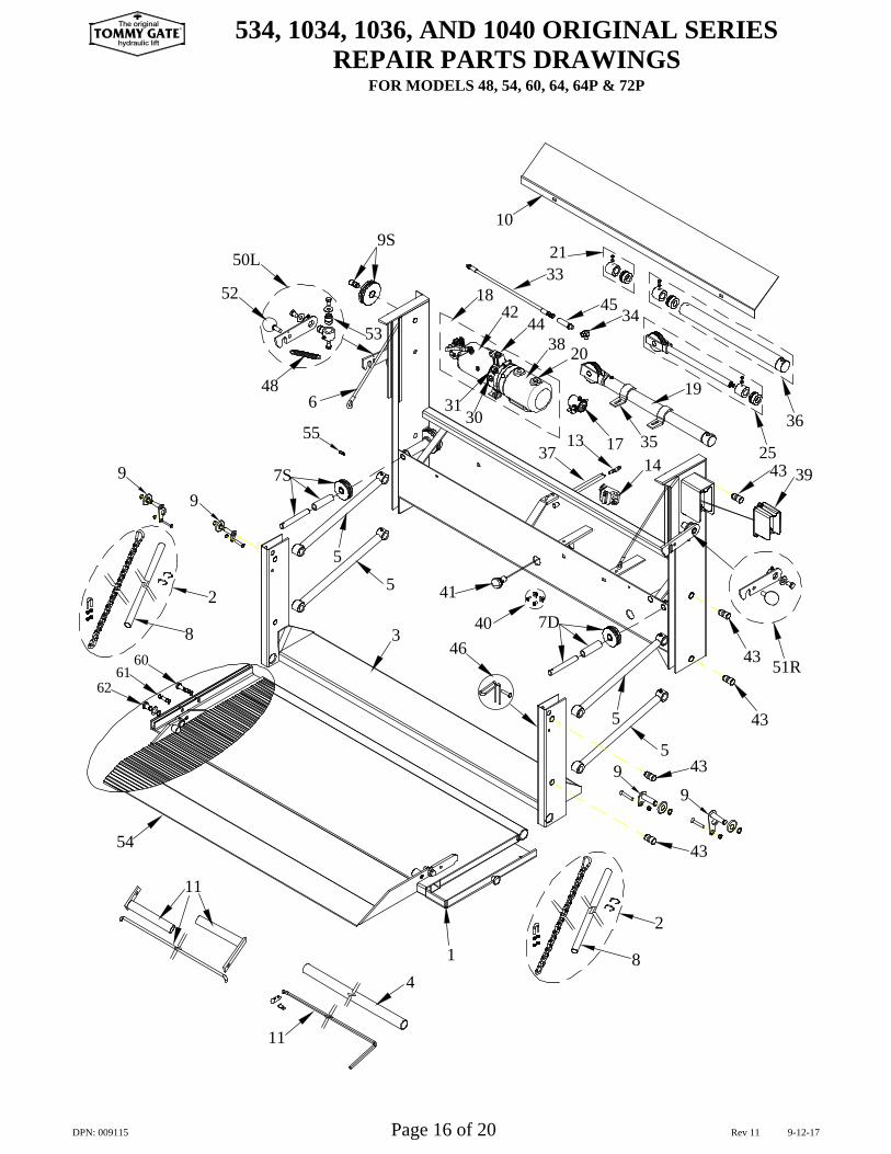
534, 1034, 1036, AND 1040 ORIGINAL SERIESREPAIR PARTS DRAWINGS
FOR MODELS 48, 54, 60, 64, 64P & 72P
7S
486
50L
524542
4453
3130
3713
38 20
18
9S
3321
10
251435
19
36
3943
DPN: 009115 Page 16 of 20 Rev 11 9-12-17
99
99
2
8
8
2
TOMMY GATEThe original
hydraulic lift
®
55
6160
1
3
46
43
43
5
5
7D
43
43
51R
14
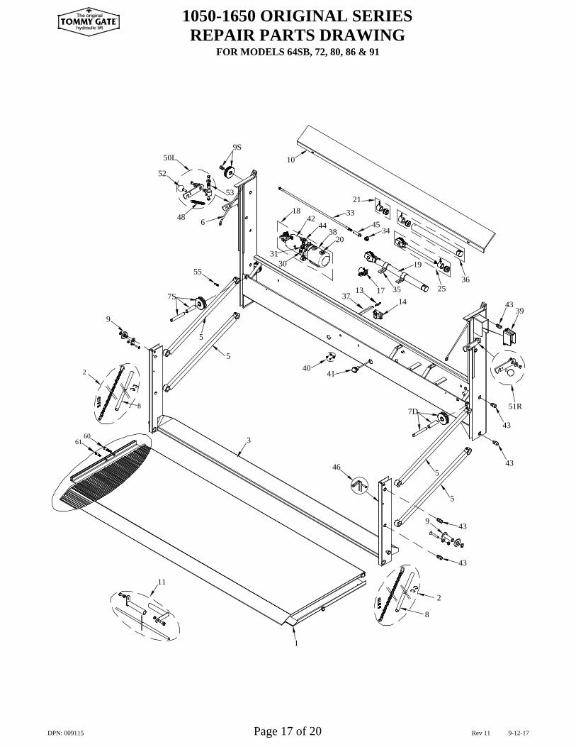
1050-1650 ORIGINAL SERIESREPAIR PARTS DRAWING
FOR MODELS 64SB, 72, 80, 86 & 91
11
9
5
7S
50L
52
48 6 44 34
540
3031
41
20
1337
38
17 35
18
10
53
9S
21
4233
45
25
19
36
4339
9
DPN: 009115 Page 17 of 20 Rev 11 9-12-17
2
8
2
8
TOMMY GATEThe original
hydraulic lift
®
55
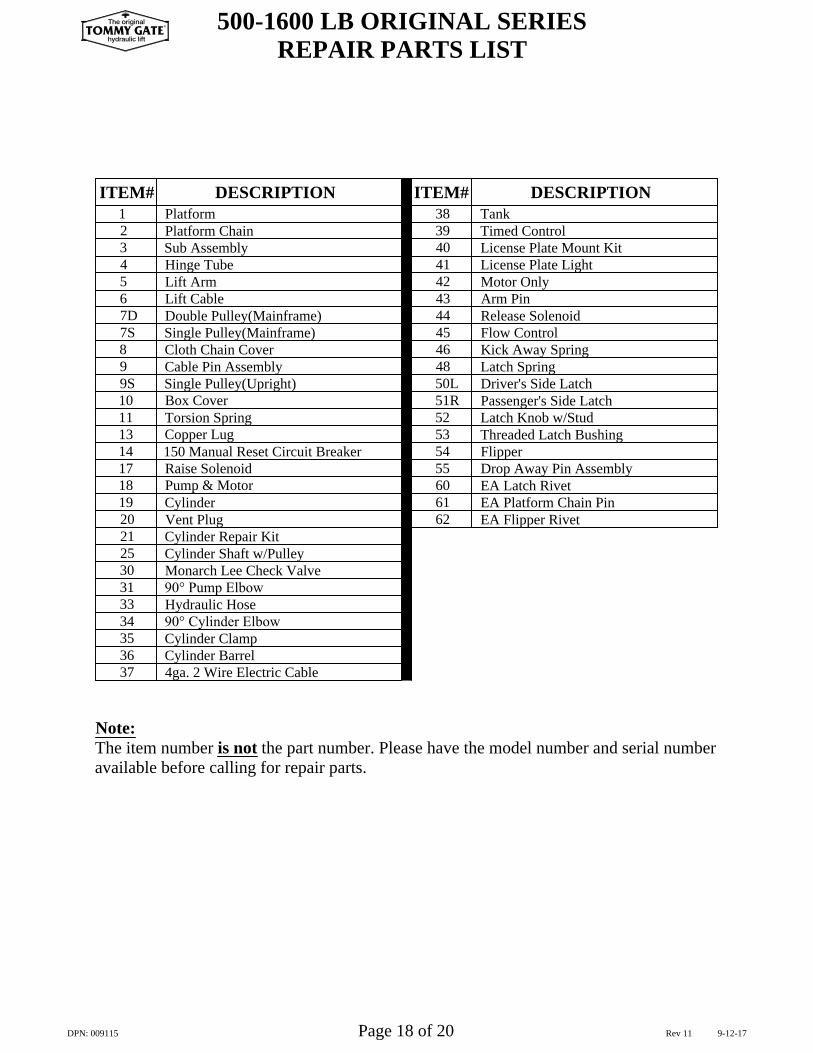
500-1600 LB ORIGINAL SERIESREPAIR PARTS LIST
Cylinder Shaft w/Pulley25
Note:The item number is not the part number. Please have the model number and serial numberavailable before calling for repair parts.
Monarch Lee Check Valve
4ga. 2 Wire Electric Cable
90° Cylinder Elbow
36
333130
35
38
37
34
Cylinder Barrel
Tank
Hydraulic Hose90° Pump Elbow
Cylinder Clamp
Cylinder Repair Kit
Single Pulley(Mainframe)
Single Pulley(Upright)
150 Manual Reset Circuit Breaker
Double Pulley(Mainframe)
DESCRIPTION
7S
21
18
2019
17
1011
9S
1413
8
Pump & Motor
Vent PlugCylinder
Raise Solenoid
Cloth Chain Cover
Box Cover
Copper LugTorsion Spring
7D
ITEM#
2
56
34
1Platform Chain
Lift CableLift ArmHinge TubeSub Assembly
Platform
Latch Knob w/StudPassenger's Side LatchDriver's Side LatchLatch Spring
Release Solenoid
Motor OnlyLicense Plate LightLicense Plate Mount KitTimed Control
Flow ControlKick Away Spring
EA Latch RivetEA Platform Chain Pin
Threaded Latch Bushing
EA Flipper Rivet
DESCRIPTION
46
53
6162
60
54 Flipper
50L
5251R
48
40
434445
4241
Arm Pin
39
ITEM#
DPN: 009115 Page 18 of 20 Rev 11 9-12-17
9 Cable Pin Assembly
TOMMY GATEThe original
hydraulic lift
®
55 Drop Away Pin Assembly
Reminders: Service the liftgate according to page 12.
Date of Service
Installed By:
Date of Purchase:
Services Performed
Model Number:
Serial Number:LIFTGATE INFORMATION
SERVICE RECORD
DPN: 009115 Page 19 of 20 Rev 11 9-12-17
TOMMY GATEThe original
hydraulic lift
®
TM
America's First Namein Liftgates
DPN: 009115 Page 20 of 20 Rev 11 9-12-17
www.tommygate.com
Manufacturing Plant:83 Bus Brown Drive
Woodbine, Iowa 51579FAX (712) 647-2417
Corporate Offices:33717 N. Scottsdale Rd. Ste 120
Scottsdale, AZ 85266FAX (602) 955-3902
(712) 847-8000
TOMMY GATEThe original
hydraulic lift
®