OWNER’S MANUAL - seat.com€¦ · Foreword This Instruction Manual and its corresponding...
339
OWNER’S MANUAL Leon
-
Upload
vuongnguyet -
Category
Documents
-
view
218 -
download
0
Transcript of OWNER’S MANUAL - seat.com€¦ · Foreword This Instruction Manual and its corresponding...

OWNER’S MANUAL
Leon
5F0012720BA
Ingl
és 5
F001
2720
BA
(10
.13)
(G
T9)
Leon
In
glés
(10
.13)

SEAT S.A. se preocupa constantemente por mantener todos sus tipos y modelos en un desarrollo continuo. Por ello le rogamos que com-prenda que, en cualquier momento, puedan producirse modificaciones del vehículo entregado en cuanto a la forma, el equipamiento y la técnica. Por esta razón, no se puede derivar derecho alguno basándose en los datos, las ilustraciones y descripciones del presente Manual.
Los textos, las ilustraciones y las normas de este manual se basan en el estado de la información en el momento de la realización de la impresión. Salvo error u omisión, la información recogida en el presente manual es válida en la fecha de cierre de su edición.
No está permitida la reimpresión, la reproducción o la traducción, total o parcial, sin la autorización escrita de SEAT.
SEAT se reserva expresamente todos los derechos según la ley sobre el “Copyright”. Reservados todos los derechos sobre modificación.
❀ Este papel está fabricado con celulosa blanqueada sin cloro.
© SEAT S.A. - Reimpresión: 15.10.13

Foreword
This Instruction Manual and its corresponding supplements should be read carefully to familiarise yourselfwith your vehicle.
Besides the regular care and maintenance of the vehicle, its correct handling will help preserve its value.
For safety reasons, always note the information concerning accessories, modifications and part replace-ments.
If selling the vehicle, give all of the on-board documentation to the new owner, as it should be kept with thevehicle.


Table of Contents
About this manual . . . . . . . . . . . . . . . . . . . 5
Content . . . . . . . . . . . . . . . . . . . . . . . . . . . . . . . . 6
Safety First . . . . . . . . . . . . . . . . . . . . . . . . . . . . 7
Safe driving . . . . . . . . . . . . . . . . . . . . . . . . . . . . . . . 7Brief introduction . . . . . . . . . . . . . . . . . . . . . . . . . 7Sitting position for vehicle occupants . . . . . . . . . 10Pedal area . . . . . . . . . . . . . . . . . . . . . . . . . . . . . . . 16Storing objects . . . . . . . . . . . . . . . . . . . . . . . . . . . 17
Seat belts . . . . . . . . . . . . . . . . . . . . . . . . . . . . . . . . . 20Brief introduction . . . . . . . . . . . . . . . . . . . . . . . . . 20Why wear seat belts? . . . . . . . . . . . . . . . . . . . . . . 22Seat belts . . . . . . . . . . . . . . . . . . . . . . . . . . . . . . . 26Seat belt tensioners . . . . . . . . . . . . . . . . . . . . . . . 29
Airbag system . . . . . . . . . . . . . . . . . . . . . . . . . . . . . 31Brief introduction . . . . . . . . . . . . . . . . . . . . . . . . . 31Front airbags . . . . . . . . . . . . . . . . . . . . . . . . . . . . . 36Knee airbag* . . . . . . . . . . . . . . . . . . . . . . . . . . . . . 39Side airbags* . . . . . . . . . . . . . . . . . . . . . . . . . . . . 40Curtain airbags . . . . . . . . . . . . . . . . . . . . . . . . . . . 43Deactivating airbags . . . . . . . . . . . . . . . . . . . . . . . 45
Child safety . . . . . . . . . . . . . . . . . . . . . . . . . . . . . . . 48Brief introduction . . . . . . . . . . . . . . . . . . . . . . . . . 48Child seats . . . . . . . . . . . . . . . . . . . . . . . . . . . . . . . 50Securing child seats . . . . . . . . . . . . . . . . . . . . . . . 53
Operating instructions . . . . . . . . . . . . . 59
Controls and displays . . . . . . . . . . . . . . . . . . . . . . 59Overview . . . . . . . . . . . . . . . . . . . . . . . . . . . . . . . . 58
Instruments and warning/control lamps . . . . 61Instruments . . . . . . . . . . . . . . . . . . . . . . . . . . . . . . 61Control lamps . . . . . . . . . . . . . . . . . . . . . . . . . . . . 69
Driver information system . . . . . . . . . . . . . . . . . . 73Information system . . . . . . . . . . . . . . . . . . . . . . . . 73
Introduction to the Easy Connect system* . . . 79System settings (CAR)* . . . . . . . . . . . . . . . . . . . . . 79
Opening and closing . . . . . . . . . . . . . . . . . . . . . . 87Central locking system . . . . . . . . . . . . . . . . . . . . . 87Anti-theft alarm system* . . . . . . . . . . . . . . . . . . . 95Emergency locking and unlocking . . . . . . . . . . . . 98Rear lid (luggage compartment) . . . . . . . . . . . . . 100Electric windows . . . . . . . . . . . . . . . . . . . . . . . . . . 102Panoramic sliding sunroof* . . . . . . . . . . . . . . . . . 106
Lights and visibility . . . . . . . . . . . . . . . . . . . . . . . . 109Lights . . . . . . . . . . . . . . . . . . . . . . . . . . . . . . . . . . . 109Sun protection equipment . . . . . . . . . . . . . . . . . . 118Windscreen wiper and rear wiper systems . . . . . 120Rear vision mirror . . . . . . . . . . . . . . . . . . . . . . . . . 125
Seats and storage . . . . . . . . . . . . . . . . . . . . . . . . . 128General notes . . . . . . . . . . . . . . . . . . . . . . . . . . . . 128Front seats . . . . . . . . . . . . . . . . . . . . . . . . . . . . . . . 129Seat functions . . . . . . . . . . . . . . . . . . . . . . . . . . . . 130Head restraints . . . . . . . . . . . . . . . . . . . . . . . . . . . 131Storage compartments . . . . . . . . . . . . . . . . . . . . . 133Power sockets . . . . . . . . . . . . . . . . . . . . . . . . . . . . 135Luggage compartment . . . . . . . . . . . . . . . . . . . . . 136Roof carrier . . . . . . . . . . . . . . . . . . . . . . . . . . . . . . 150
Air conditioning . . . . . . . . . . . . . . . . . . . . . . . . . . . 153Heating, ventilation, cooling . . . . . . . . . . . . . . . . 153
Driving . . . . . . . . . . . . . . . . . . . . . . . . . . . . . . . . . . . . 162Steering . . . . . . . . . . . . . . . . . . . . . . . . . . . . . . . . . 162Ignition lock . . . . . . . . . . . . . . . . . . . . . . . . . . . . . . 162Kick-down . . . . . . . . . . . . . . . . . . . . . . . . . . . . . . . 166Handbrake . . . . . . . . . . . . . . . . . . . . . . . . . . . . . . . 166Hill driving assistant* . . . . . . . . . . . . . . . . . . . . . . 168Speed warning function . . . . . . . . . . . . . . . . . . . . 168Start-Stop system* . . . . . . . . . . . . . . . . . . . . . . . . 169Manual gearbox . . . . . . . . . . . . . . . . . . . . . . . . . . 172Automatic gearbox/DSG automatic gearbox* . . . 173
Driver assistance systems . . . . . . . . . . . . . . . . . . 184Cruise control system (CCS)* . . . . . . . . . . . . . . . . 184Adaptive cruise control (ACC)* . . . . . . . . . . . . . . . 189Monitoring system Front Assist* . . . . . . . . . . . . . 202Lane Assist system* . . . . . . . . . . . . . . . . . . . . . . . 207SEAT Drive Modes* . . . . . . . . . . . . . . . . . . . . . . . . 211Tiredness detection (break recommendation)* . 213Tyre monitoring systems . . . . . . . . . . . . . . . . . . . . 214Parking aid . . . . . . . . . . . . . . . . . . . . . . . . . . . . . . 217
Practical Tips . . . . . . . . . . . . . . . . . . . . . . . . . 222
Intelligent technology . . . . . . . . . . . . . . . . . . . . . 222Electronic Stability Control (ESC) . . . . . . . . . . . . . 222Brakes . . . . . . . . . . . . . . . . . . . . . . . . . . . . . . . . . . 224Electro-mechanical steering . . . . . . . . . . . . . . . . . 225Progressive steering . . . . . . . . . . . . . . . . . . . . . . . 226Power Management . . . . . . . . . . . . . . . . . . . . . . . 226Information recorded in the control units . . . . . . 228
3Table of Contents

Driving and the environment . . . . . . . . . . . . . . . 230Running in the engine . . . . . . . . . . . . . . . . . . . . . 230Driving through flooded roads . . . . . . . . . . . . . . . 230Installation of exhaust gas filtration systems . . . 230Economic and ecological driving . . . . . . . . . . . . . 231Environmental friendliness . . . . . . . . . . . . . . . . . 232
Trailer . . . . . . . . . . . . . . . . . . . . . . . . . . . . . . . . . . . . . 234Trailer towing . . . . . . . . . . . . . . . . . . . . . . . . . . . . . 234Retrofitting a towing bracket* . . . . . . . . . . . . . . . 236
Care and cleaning . . . . . . . . . . . . . . . . . . . . . . . . . 238General information . . . . . . . . . . . . . . . . . . . . . . . 238Care of vehicle exterior . . . . . . . . . . . . . . . . . . . . . 238Care of the vehicle interior . . . . . . . . . . . . . . . . . . 242
Checking and refilling levels . . . . . . . . . . . . . . . 246Fuel . . . . . . . . . . . . . . . . . . . . . . . . . . . . . . . . . . . . 246Filling the tank . . . . . . . . . . . . . . . . . . . . . . . . . . . . 248Bonnet . . . . . . . . . . . . . . . . . . . . . . . . . . . . . . . . . . 251Engine oil . . . . . . . . . . . . . . . . . . . . . . . . . . . . . . . . 253Cooling system . . . . . . . . . . . . . . . . . . . . . . . . . . . 257Brake fluid . . . . . . . . . . . . . . . . . . . . . . . . . . . . . . . 259Battery . . . . . . . . . . . . . . . . . . . . . . . . . . . . . . . . . . 260Windscreen washer reservoir and wiper blades . 262
Wheels and tyres . . . . . . . . . . . . . . . . . . . . . . . . . . 265Wheels . . . . . . . . . . . . . . . . . . . . . . . . . . . . . . . . . . 265
Accessories and modifications to the vehicle 272Accessories, replacement parts and repairs . . . . 272Technical modifications . . . . . . . . . . . . . . . . . . . . 272Radio transmitters and business equipment . . . 272
Emergencies . . . . . . . . . . . . . . . . . . . . . . . . . . . . . . 274General information . . . . . . . . . . . . . . . . . . . . . . . 274Equipment . . . . . . . . . . . . . . . . . . . . . . . . . . . . . . . 274Tyre repair kit . . . . . . . . . . . . . . . . . . . . . . . . . . . . . 275Changing a wheel . . . . . . . . . . . . . . . . . . . . . . . . . 277Spare wheel . . . . . . . . . . . . . . . . . . . . . . . . . . . . . . 282
Jump starting . . . . . . . . . . . . . . . . . . . . . . . . . . . . . 283Towing and tow-starting the vehicle . . . . . . . . . . 286
Fuses and bulbs . . . . . . . . . . . . . . . . . . . . . . . . . . . 291Fuses . . . . . . . . . . . . . . . . . . . . . . . . . . . . . . . . . . . 291Bulbs . . . . . . . . . . . . . . . . . . . . . . . . . . . . . . . . . . . 293Changing bulbs in headlight unit . . . . . . . . . . . . 295Changing bulb for front fog light . . . . . . . . . . . . . 297Changing tail light bulbs (on side panel) . . . . . . 299Changing tail light bulbs (on rear lid) . . . . . . . . . 301Changing number plate light bulbs. . . . . . . . . . . 303
Technical specifications . . . . . . . . . . . . 304
Technical specifications . . . . . . . . . . . . . . . . . . . . 304Important . . . . . . . . . . . . . . . . . . . . . . . . . . . . . . . . 304Vehicle identification data . . . . . . . . . . . . . . . . . . 305Information on fuel consumption . . . . . . . . . . . . 306Towing a trailer . . . . . . . . . . . . . . . . . . . . . . . . . . . 307Wheels . . . . . . . . . . . . . . . . . . . . . . . . . . . . . . . . . . 307Engine specifications . . . . . . . . . . . . . . . . . . . . . . 309Dimensions . . . . . . . . . . . . . . . . . . . . . . . . . . . . . . 323Filling capacities . . . . . . . . . . . . . . . . . . . . . . . . . . 323
Index . . . . . . . . . . . . . . . . . . . . . . . . . . . . . . . . . . . 325
4 Table of Contents

5About this manual
About this manual
What you should know before reading this manual
This manual contains a description of the equipment supplied with the ve-hicle at the time of press. Some of the equipment hereunder described willnot be available until a later date, or is only available in certain markets.
Because this is a general manual for the LEON range, some of the equip-ment and functions that are described in this manual are not included in alltypes or variants of the model; they may vary or be modified in accordancewith technical or market requirements; this cannot be interpreted as dis-honest advertising.
The illustrations are intended as a general guide and may vary from theequipment fitted in your vehicle in some details.
The direction indications (left, right, front, rear) appearing in this manual re-fer to the normal forward working direction of the vehicle except when oth-erwise indicated.
The equipment marked with an asterisk* is fitted as standard only incertain versions, and is only supplied as optional extras for some ver-sions, or are only offered in certain countries.
All registered marks are indicated with ®. Although the copyright sym-bol does not appear, it is a copyrighted mark.
The section is continued on the following page.
Marks the end of a section.
WARNING
Texts preceded by this symbol contain information on safety. They warnyou about possible dangers of accident or injury.
®
CAUTIONTexts with this symbol draw your attention to potential sources of damageto your vehicle.
For the sake of the environmentTexts preceded by this symbol contain relevant information concerning envi-ronmental protection.
NoteTexts preceded by this symbol contain additional information.
6 Content
ContentThis manual is structured to provide the information you need in an organ-ised way. The content of this Manual is divided into sections which belongto chapters (e.g. “Air conditioning”). The entire manual is divided into fivelarge parts which are:
1. Safety First
Information about the vehicle equipment relating to passive safety such asseat belts, airbags, seats, etc.
2. Operating instructions
Information about the distribution of controls in the driver position of yourvehicle, about the seat adjustment possibilities, about how to create a suit-able climate in the vehicle interior, etc.
3. Practical Tips
Advice relating to the driving, caring and maintenance of your vehicle andcertain problems you can solve yourself.
4. Technical specifications
Figures, values and the dimensions of your vehicle.
5. Alphabetic index
At the end of this manual there is a detailed alphabetical index, this willhelp you to quickly find the information you require.

7Safe driving
Safety First
Safe driving
Brief introduction
Dear SEAT Driver
Safety first!
This chapter contains important information, tips, suggestions andwarnings that you should read and consider for both your ownsafety and for your passengers' safety.
WARNING
● This manual contains important information about the operation ofthe vehicle, both for the driver and the passengers. The other sections ofthe on-board documentation also contain further information that youshould be aware of for your own safety and for the safety of your passen-gers.
● Ensure that the onboard documentation is kept in the vehicle at alltimes. This is especially important when lending or selling the vehicle toanother person.
Safety equipment
The safety equipment is a part of the occupant protectionsystem and can reduce the risk of injury in the event of acci-dent.
Never put your safety or the safety of your passengers in danger. In theevent of an accident, the safety equipment may reduce the risk of injury.The following list includes most of the safety equipment in your SEAT:
● Three-point seat belts
● Belt tension limiters for the front and rear side seats
● Belt tensioners for the front seats
● Front airbags
● knee airbags,
● Side airbags in the front seat backrests
● Side airbags in the rear seat backrests*
● Curtain airbags
● ISOFIX anchor points for child seats in the rear side seats with the ISOFIXsystem,
● Height-adjustable front head restraints
● Rear head restraints with in-use position and non-use position
● Adjustable steering column
The safety equipment mentioned above works together to provide you andyour passengers with the best possible protection in the event of an acci-dent. However, these safety systems can only be effective if you and your
Safety First Operating instructions Practical Tips Technical specifications
8 Safe driving
passengers are sitting in a correct position and use this equipment proper-ly.
Therefore, information is provided about why this equipment is so impor-tant, how it protects you, what you have to consider when using it and howyou and your passengers can achieve the greatest possible benefit from thesafety equipment fitted. This manual includes important warnings that youand your passengers should note in order to reduce the risk of injury.
Safety is everyone's business!
Before starting every trip
The driver is always responsible for the safety of the passen-gers and the safe operation of the vehicle.
For your own safety and the safety of your passengers, always notethe following points before every trip:
– Make sure that the vehicle's lights and turn signals are workingproperly.
– Check tyre pressure.
– Ensure that all windows provide a clear and good view of thesurroundings.
– Make sure all luggage is secured ⇒ page 17.
– Make sure that no objects can interfere with the pedals.
– Adjust front seat, head restraint and rear vision mirrors properlyaccording to your size.
– Ensure that the passengers in the rear seats always have thehead restraints in the in-use position ⇒ page 15
– Instruct passengers to adjust the head restraints according totheir height.
– Protect children with appropriate child seats and properly ap-plied seat belts ⇒ page 48.
– Assume the correct sitting position. Instruct your passengers al-so to assume a proper sitting position. ⇒ page 10.
– Fasten your seat belt securely. Instruct your passengers also tofasten their seat belts properly. ⇒ page 20.
What affects driving safety?
Driving safety is largely determined by your driving styleand the personal behaviour of all vehicle occupants.
As a driver, you are responsible for yourself and your passengers.When your concentration or driving safety is affected by any cir-cumstance, you endanger yourself as well as others on the road⇒ , for this reason:
– Always pay attention to traffic and do not get distracted by pas-sengers or telephone calls.
– Never drive when your driving ability is impaired (e.g. by medi-cation, alcohol, drugs).
– Observe traffic laws and speed limits.

9Safe driving
– Always reduce your speed as appropriate for road, traffic andweather conditions.
– When travelling long distances, take breaks regularly - at leastevery two hours.
– If possible, avoid driving when you are tired or stressed.
WARNING
When driving safety is impaired during a trip, the risk of injury and acci-dents increases.
Safety First Operating instructions Practical Tips Technical specifications
10 Safe driving
Sitting position for vehicle occupants
Introduction
WARNING
● The front seats, head restraints and seat belts must always be adjus-ted to the size of the vehicle occupant to provide you and your passen-gers with the greatest possible protection.
● Ensure your correct sitting position before setting off, and do notchange this during the journey. Also advise your passengers to ensuretheir correct sitting positions not to be changed.
● A vehicle occupant sitting in an incorrect position is at risk of seriousinjury in the event that an airbag is activated.
● If the passengers in the rear seats are not sitting in an upright posi-tion, they are more likely to be injured due to the incorrect position of theseat belts.
● It is important that the driver keeps at a minimum of 25 cm from thesteering wheel. It is important that the passenger keeps at a minimum of25 cm from the dash panel. The airbag system will not be able to give therequired protection if the minimum distance is not observed. This cancause a risk of fatal injury!
● When driving, always hold the steering wheel with both hands on theoutside part at the 9 o'clock and 3 o'clock positions. Never hold thesteering wheel at the 12 o'clock position, or in any other manner (e.g. inthe centre of the steering wheel or along its interior edge). In such cases,if the airbag is triggered, you may sustain injuries to the arms, handsand head.
● The backrests must not be reclined too far back while driving. Thiscould limit the effect of the seat belts and the airbag system. Risk of in-jury!
WARNING (Continued)
● Objects must not be placed in the footwell, as they could move to thearea of the pedals in the event of a braking manoeuvre or change of direc-tion. This would prevent the clutch, brake or accelerator from beingpressed.
● Always keep your feet on the footwell when the vehicle is moving;never rest them on the dash panel, on the window or on the seat! An in-correct sitting position exposes you to an increased risk of injury in caseof a sudden braking or an accident. If the airbag is triggered, you couldsustain severe injuries due to an incorrect sitting position!

11Safe driving
Correct sitting position for driver
The correct sitting position for the driver is important forsafe and relaxed driving.
Fig. 1 The correct dis-tance between driver andsteering wheel
Fig. 2 Correct head re-straint position for driver
For your own safety and to reduce the risk of injury in the event ofan accident, we recommend the following adjustments for the driv-er:
– Adjust the steering wheel so that there is a distance of at least25 cm between the steering wheel and the centre of your chest⇒ Fig. 1.
– Move the driver seat forwards or backwards so that you are ableto press the accelerator, brake and clutch pedals to the floorwith your knees still slightly angled ⇒ .
– Ensure that you can reach the highest point of the steeringwheel without lifting your back from the seat.
– Adjust the head restraint so that its upper edge is at the samelevel as the top of your head, or as close as possible to thesame level as the top of your head ⇒ Fig. 2.
– Move the seat backrest to an upright position so that your backrests completely against it.
– Fasten your seat belt securely ⇒ page 20.
– Keep both feet in the footwell so that you have the vehicle un-der control at all times.
Adjustment of the driver seat ⇒ page 129.
Safety First Operating instructions Practical Tips Technical specifications
12 Safe driving
WARNING
● An incorrect sitting position of the driver can lead to severe injuries.
● Adjust the driver seat so that there is at least 25 cm distance betweenthe centre of the chest and the centre of the steering wheel ⇒ Fig. 1. Ifyou are sitting closer than 25 cm, the airbag system cannot protect youproperly.
● If your physical constitution prevents you from maintaining the mini-mum distance of 25 cm, contact a specialised workshop. The workshopwill help you decide if special specific modifications are necessary.
● When driving, always hold the steering wheel with both hands on theoutside of the ring at the 9 o'clock and 3 o'clock positions. This reducesthe risk of injury when the driver airbag is triggered.
● Never hold the steering wheel at the 12 o'clock position, or in anyother manner (e.g. in the centre of the steering wheel). In such cases, ifthe airbag is triggered, you may sustain injuries to the arms, hands andhead.
● To reduce the risk of injury to the driver during sudden braking ma-noeuvres or an accident, never drive with the backrest tilted far back! Theairbag system and seat belts can only provide optimal protection whenthe backrest is in an upright position and the driver is wearing his or herseat belt correctly. The further the seat backrests are tilted to the rear,the greater the risk of injury due to incorrect positioning of the belt webor to the incorrect sitting position!
● Adjust the head restraint properly to achieve optimal protection.
Correct sitting position for front passenger
The front passenger must sit at least 25 cm away from thedash panel so that the airbag can provide the greatest pos-sible protection in the event that it is triggered.
For your own safety and to reduce the risk of injury in the event ofan accident, we recommend the following adjustments for the frontpassenger:
– Move the front passenger seat back as far as possible ⇒ .
– Move the seat backrest to an upright position so that your backrests completely against it.
– Adjust the head restraint so that its upper edge is at the samelevel as the top of your head, or as close as possible to thesame level as the top of your head ⇒ page 14.
– Always keep both feet in the footwell in front of the front pas-senger seat.
– Fasten your seat belt securely ⇒ page 20.
It is possible to deactivate the front passenger airbag in exceptional circum-stances ⇒ page 27.
Adjusting the front passenger seat ⇒ page 129.

13Safe driving
WARNING
● An incorrect sitting position of the front passenger can lead to severeinjuries.
● Adjust the front passenger seat so that there is at least 25 cm be-tween your chest and the dash panel. If you are sitting closer than 25 cm,the airbag system cannot protect you properly.
● If your physical constitution prevents you from maintaining the mini-mum distance of 25 cm, contact a specialised workshop. The workshopwill help you decide if special specific modifications are necessary.
● Always keep your feet in the footwell when the vehicle is moving;never rest them on the dash panel, out the window or on the seat. An in-correct sitting position exposes you to an increased risk of injury in caseof a sudden braking or an accident. If the airbag is triggered, you couldsustain severe injuries due to an incorrect sitting position.
● To reduce the risk of injury to the front passenger in events such assudden braking manoeuvres or an accident, never travel with the back-rest tilted far back! The airbag system and seat belts can only provide op-timal protection when the backrest is in an upright position and the frontpassenger is wearing his or her seat belt properly. The further the seatbackrests are tilted to the rear, the greater the risk of injury due to incor-rect positioning of the belt web or to the incorrect sitting position!
● Adjust the head restraint correctly in order to achieve maximum pro-tection.
Correct sitting position for passengers in the rear seats
Passengers in the rear seats must sit up straight, keep theirfeet in the footwells, have the head restraints positioned foruse and wear their seat belts properly.
To reduce the risk of injury in the event of a sudden braking ma-noeuvre or an accident, passengers on the rear seat bench mustconsider the following:
– Adjust the head restraint to the correct position. ⇒ page 15
– Always keep both feet in the footwell in front of the rear seat.
– Fasten your seat belt securely ⇒ page 20.
– Use an appropriate child restraint system when you take chil-dren in the vehicle ⇒ page 48.
WARNING
● If the passengers in the rear seats are not sitting properly, they couldsustain severe injuries.
● Adjust the head restraint correctly in order to achieve maximum pro-tection.
● Seat belts can only provide optimal protection when seat backrestsare in an upright position and the vehicle occupants are wearing theirseat belts correctly. If passengers In the rear seats are not sitting in anupright position, the risk of injury due to incorrect positioning of the seatbelt increases.
Safety First Operating instructions Practical Tips Technical specifications

14 Safe driving
Correct adjustment of front seat head restraints
Properly adjusted head restraints are an important part ofpassenger protection and can reduce the risk of injuries inmost accident situations.
Fig. 3 Correctly adjustedhead restraint viewedfrom the front
Fig. 4 Correctly adjustedhead restraint viewedfrom the side
Adjust the head restraint correctly in order to achieve maximumprotection.
– Adjust the head restraint so that its upper edge is at the samelevel as the top of your head, or as close as possible to thesame level as the top of your head and, at the very least, at eyelevel. ⇒ Fig. 3 and ⇒ Fig. 4.
Adjusting the head restraints ⇒ page 131
WARNING
● Travelling with the head restraints removed or improperly adjustedincreases the risk of severe injuries.
● Incorrectly adjusted head restraints could result in death in the eventof a collision or accident.
● Incorrectly adjusted head restraints also increase the risk of injuryduring sudden or unexpected driving or braking manoeuvres.
● The head restraints must always be adjusted according to the heightof the passenger.

15Safe driving
Correct adjustment of rear seat head restraints
Properly adjusted head restraints are an important part ofthe passenger protection and can reduce the risk of injuriesin most accident situations
Fig. 5 Head restraints incorrect position
Fig. 6 Head restraint po-sition warning label
Rear head restraints
– The rear head restraints have 2 positions: use and non-use.
– One position for use (head restraint raised) ⇒ Fig. 5. In this po-sition, the head restraints are used normally, protecting pas-sengers along with the rear seat belts.
– And one position for non-use (head restraint lowered).
– To fit the head restraints in position for use, pull on the edgeswith both hands in the direction of the arrow.
WARNING
● Under no circumstances should the rear passengers travel while thehead restraints are in the non-use position. See the warning label loca-ted on the rear side fixed window ⇒ Fig. 6.
● Do not swap the centre rear head restraint with either of the outerseat rear head restraints.
● Risk of injury in case of an accident!
CAUTIONNote the instructions on the adjustment of the head restraints ⇒ page 131.
Examples of incorrect sitting positions
An incorrect sitting position can lead to severe injuries to ve-hicle occupants.
Seat belts can provide optimal protection only when the belt websare properly positioned. Incorrect sitting positions substantially re-duce the protective function of seat belts and increase the risk of
Safety First Operating instructions Practical Tips Technical specifications

16 Safe driving
injury due to incorrect seat belt position. As the driver, you are re-sponsible for all passengers, especially children.
– Never allow anyone to assume an incorrect sitting position inthe vehicle while travelling ⇒ .
The following list contains examples of sitting positions that could be dan-gerous for all vehicle occupants. The list is not complete, but we would liketo make you aware of this issue.
Therefore, whenever the vehicle is in motion:
● Never stand in the vehicle.
● Never stand on the seats.
● Never kneel on the seats.
● Never tilt your seat backrest far to the rear.
● Never lean against the dash panel.
● Never lie on the rear bench.
● Never sit on the front edge of a seat.
● Never sit sideways.
● Never lean out of a window.
● Never put your feet out of a window.
● Never put your feet on the dash panel.
● Never put your feet on the surface of a seat.
● Do not allow anyone to travel in the footwell.
● Never travel without wearing the seat belt.
● Do not allow anyone to travel in the luggage compartment.
WARNING
● Any incorrect sitting position increases the risk of severe injuries.
● Sitting in an incorrect position exposes the vehicle occupants to se-vere injuries if airbags are triggered, by striking a vehicle occupant whohas assumed an incorrect sitting position.
● Before the vehicle moves, assume the proper sitting position andmaintain it throughout the trip. Before every trip, instruct your passen-gers to sit properly and to stay in this position during the trip ⇒ page 10,Sitting position for vehicle occupants.
Pedal area
Pedals
The operation of all pedals must never be impaired by ob-jects or floor mats.
– Ensure that you can always press the accelerator, brake andclutch pedals unimpaired to the floor.
– Ensure that the pedals can return unimpaired to their initial po-sitions.
Use only floor mats which leave the pedal area free and can be securely fas-tened on the footwell.
If a brake circuit fails, the brake pedal must be pressed down thoroughly inorder to stop the vehicle.

17Safe driving
Wearing suitable shoes
Always wear shoes which support your feet properly and give you a goodfeeling for the pedals.
WARNING
● Restricting pedal operation can lead to critical situations while driv-ing.
● Never place objects on the driver footwell. An object could move intothe pedal area and impair pedal operation. In the event of a sudden driv-ing or braking manoeuvre, you will not be able to operate the brake,clutch or accelerator pedal. Risk of accident!
Floor mats on the driver side
Only floor mats may be used which can be securely fastenedin the footwell and do not impair operation of the pedals.
– Ensure that the floor mats are securely fastened during the tripand do not obstruct the pedals ⇒ .
Only use floor mats which leave the pedals clear and which are secured toprevent them from slipping. You can obtain suitable floor mats from a speci-alised dealership. Fasteners* for floor mats are fitted in the footwells.
WARNING
● If the pedals are obstructed, an accident may occur. Risk of seriousinjuries.
● Ensure that the floor mats are always securely attached.
● Never lay or fit floor mats or other floor coverings over the originalfloor mats. This would reduce the pedal area and could obstruct the ped-als. Risk of accident.
Storing objects
Loading the luggage compartment
All luggage and other loose objects must be safely securedin the luggage compartment.
Unsecured objects which shift back and forth could impair the driv-ing safety or driving characteristics of the vehicle by shifting thecentre of gravity.
– Distribute the load evenly in the luggage compartment.
– Place heavy objects as far forward as possible in the luggagecompartment.
– Place the heavy objects first.
– Secure heavy objects to the fitted fastening rings ⇒ page 18.
Safety First Operating instructions Practical Tips Technical specifications

18 Safe driving
WARNING
● Loose luggage and other objects in the luggage compartment couldcause serious injuries.
● Always stow objects in the luggage compartment and secure them onthe fastening rings.
● Use suitable straps to secure heavy objects.
● During sudden manoeuvres or accidents, loose objects can be thrownforward, injuring vehicle occupants or passers-by. This increased risk ofinjury will be further increased if a loose object is struck by an inflatingairbag. If this happens, objects can be transformed into “missiles”. Riskof fatal injury.
● Please note that the centre of gravity may shift when transportingheavy objects; this may affect vehicle handling and lead to an accident.Therefore, it is essential to adjust your speed and driving style accord-ingly, to avoid accidents.
● Never exceed the allowed axle weights or allowed maximum weight.If the allowed axle load or the allowed total weight is exceeded, the driv-ing characteristics of the vehicle may change, leading to accidents, inju-ries and damage to the vehicle.
● Never leave your vehicle unattended, especially when the rear lid isopen. Children could climb into the luggage compartment, closing thedoor behind them; they will be trapped and run the risk of death.
● Never allow children to play in or around the vehicle. Close and lockall the doors and rear lid when you leave the vehicle. Before you lock thevehicle, make sure that there are no adults or children in the vehicle.
● Never transport passengers in the luggage compartment. All vehicleoccupants must have their seat belt fastened ⇒ page 20.
Note● Air circulation in the vehicle helps reduce fogging of the windows. Usedair escapes through ventilation slits in the side trim of the luggage compart-ment. Ensure that the ventilation slits are never covered.
● Straps for securing the load to the fastening rings are commerciallyavailable.
Fastening rings*
There can be four fastening rings in the luggage compart-ment for fastening luggage and other objects.
– Always use suitable and undamaged straps to secure luggageand other objects to the fastening rings ⇒ in Loading the lug-gage compartment on page 18.
Bear in mind that in the case of a collision or accident, even small and lightobjects that are not firmly fixed can be projected at the occupants causinginjury.
Example: An object weighing 4.5 kg is lying unsecured in the vehicle. Dur-ing a frontal collision at a speed of 50 km/h (30 mph), this object generatesa force corresponding to 20 times its weight. That means that the effectiveweight of the object increases to about 90 kg. You can imagine the severityof the injuries which might be sustained if this object strikes an occupant asit flies through the interior of the vehicle. This increased risk of injury will befurther increased if a loose object is struck by an inflating airbag.

19Safe driving
WARNING
● If pieces of luggage or other objects are secured to the fasteningrings with inappropriate or damaged retaining cords, injuries could besustained in the event of braking manoeuvres or accidents.
● To prevent pieces of luggage or other objects from flying forward, al-ways use appropriate retaining cords which are secured to the fasteningrings.
● Never secure a child seat on the fastening rings.
Safety First Operating instructions Practical Tips Technical specifications

20 Seat belts
Seat belts
Brief introduction
Before driving: remember your seat belt!
Wearing a seat belt properly can save your life!
In this section you will learn the importance of wearing seat belts,how they work and how to properly fasten, adjust and wear them.
– Read and consider all the information as well as the warnings inthis chapter.
WARNING
● If seat belts are worn incorrectly or not at all, the risk of severe inju-ries increases.
● Properly worn seat belts can reduce severe injuries in case of suddenbraking manoeuvres or accidents. For safety reasons, you and all othervehicle occupants must always wear the seat belts properly while the ve-hicle is moving.
● Pregnant women or people with physical disabilities must also useseat belts. Like all other vehicle occupants, these people can also sustainsevere injuries if they are not wearing their seat belts properly.
Number of seats
Your vehicle has five seats, two in the front and three in the rear. Each seatis equipped with a three-point seat belt.
In some versions, your vehicle is approved only for four seats. Two frontseats and two rear seats.
WARNING
● Never transport more than the permitted amount of people in your ve-hicle.
● Every vehicle occupant must properly fasten and wear the seat beltbelonging to his or her seat. Children must be protected with an appro-priate child restraint system.
Seat belt warning lamp*
The control lamp acts as a reminder to the driver to fastenthe seat belt.
Fig. 7 Indication of thestate of the seat belts inthe rear seats on thedash panel.
Before starting the vehicle:
– Fasten your seat belt securely.

21Seat belts
– Instruct your passengers to fasten their seat belts properly be-fore driving off.
– Protect children by using a child seat according to the child'sheight and weight.
After the ignition has been switched on, the warning lamp on the instru-ment panel lights up1) if the driver has not fastened his/her seat belt. Anaudible warning is heard if the vehicle is driven at more than 30 km/h (18mph).
The warning lamp* is switched off if the driver seat belt is fastened whilethe ignition is switched on.
Indication of the state of the seat belts in the rear seats.
The seat belt status display ⇒ Fig. 7 on the instrument panel informs thedriver, when the ignition is switched on, whether the passengers in the rearseats have fastened their seat belts. The symbol indicates that the pas-senger in this seat has fastened “his or her” seat belt.
When a seat belt in the rear seats is fastened or unfastened, the seat beltstatus is displayed for approx. 30 seconds. The indication can be hidden bypressing the 0.0/SET button on the dash panel.
The seat belt status flashes for a maximum of 30 seconds when a seat beltin the rear seats is unfastened while the vehicle is in motion. An audiblewarning will also be heard if the vehicle is travelling at over 25 km/h(15 mph).
1) Depending on the model version
Safety First Operating instructions Practical Tips Technical specifications

22 Seat belts
Why wear seat belts?
Physical principles of frontal collisions
In the event of a frontal collision, a large amount of kineticenergy must be absorbed.
Fig. 8 Vehicle about tohit a wall: the occupantsare not wearing seatbelts
Fig. 9 The vehicle hitsthe wall: the occupantsare not wearing seatbelts
It is easy to explain how the laws of physics work in the case of a head-oncollision: When a vehicle starts moving ⇒ Fig. 8, a certain amount of energyknown as kinetic energy is produced in the vehicle and its occupants.
The amount of kinetic energy depends on the speed of the vehicle and theweight of the vehicle and its passengers. The higher the speed and thegreater the weight, the more energy there is to be released in an accident.
The most significant factor, however, is the speed of the vehicle. If thespeed doubles from 25 km/h to 50 km/h, for example, the kinetic energy ismultiplied by four.
Because the vehicle occupants in our example are not restrained by seatbelts, all of the occupants' kinetic energy has to be absorbed at the point ofimpact ⇒ Fig. 9.
Even at speeds of 30 km/h to 50 km/h, the forces acting on bodies in a col-lision can easily exceed one tonne (1000 kg). At greater speed these forcesare even higher.

23Seat belts
Vehicle occupants not wearing seat belts are not “attached” to the vehicle.In a head-on collision, they will move forward at the same speed their vehi-cle was travelling just before the impact. This example applies not only tohead-on collisions, but to all accidents and collisions.
The danger of not using the seat belt
The general belief that the passengers can protect them-selves with their hands in a minor collision is false.
Fig. 10 A driver notwearing a seat belt isthrown forward violently
Fig. 11 The unbeltedpassenger in the rearseat is thrown forward vi-olently, hitting the driverwearing a seat belt
Even at low speeds the forces acting on the body in a collision are so greatthat it is not possible to brace oneself with one's hands. In a frontal colli-sion, unbelted vehicle occupants are thrown forward and will make violentcontact with the steering wheel, dash panel, windscreen or whatever else isin the way ⇒ Fig. 10.
The airbag system is not a substitute for seat belts. When triggered, airbagsprovide only additional protection. All occupants (including the driver) mustwear seat belts properly at all times during the trip. This will reduce the riskof severe injuries in the event of an accident – regardless of whether an air-bag is fitted for the seat or not.
Note that airbags can be triggered only once. To achieve the best possibleprotection, the seat belt must always be worn properly so that you will beprotected in accidents in which no airbag is deployed.
It is also important for the rear passengers to wear seat belts properly, asthey could otherwise be thrown forward violently through the vehicle interi-or in an accident. Passengers in the rear seats who do not use seat beltsendanger not only themselves but also the front occupants ⇒ Fig. 11.
Safety First Operating instructions Practical Tips Technical specifications

24 Seat belts
Seat belt protection
Passengers not wearing seat belts risk severe injuries in theevent of an accident.
Fig. 12 A driver wearingthe seat belt properly issecured by the belt insharp braking
Properly worn seat belts hold the vehicle occupants in the correct sitting po-sitions and substantially reduce the kinetic energy in the event of an acci-dent. Seat belts also help to prevent uncontrolled movements that couldlead to severe injuries. In addition, properly worn seat belts reduce the dan-ger of being thrown from the vehicle.
Vehicle occupants wearing their seat belts correctly benefit greatly from theability of the belts to absorb kinetic energy. The front part of your vehicleand other passive safety features (such as the airbag system) are also de-signed to absorb the kinetic energy released in a collision. Taken together,all these features reduce the releasing kinetic energy and consequently, therisk of injury.
Our examples describe frontal collisions. Of course, properly worn seat beltssubstantially reduce the risk of injury in all other types of accidents. This iswhy it is so important to fasten seat belts before every trip, even when "justdriving around the corner".
Ensure that your passengers wear their seat belts as well. Accident statisticshave shown that wearing seat belts is an effective means of substantiallyreducing the risk of injury and improving the chances of survival in a seri-ous accident. Furthermore, properly worn seat belts improve the protectionprovided by airbags in the event of an accident. For this reason, wearing aseat belt is required by law in most countries.
Although your vehicle is equipped with airbags, the seat belts must be fas-tened and worn. The front airbags, for example, are only triggered in somefrontal accidents. The front airbags will not be triggered during minor frontalcollisions, minor side collisions, rear collisions, overturns or accidents inwhich the airbag trigger threshold value in the control unit is not exceeded.
Therefore, you should always wear your seat belt and ensure that all vehicleoccupants have fastened their seat belts properly before you drive off!
Safety instructions on using seat belts
If seat belts are used correctly, they can considerably reducethe risk of injury in an accident.
– Always wear the seat belt as described in this section.
– Ensure that the seat belts can be fastened at all times and arenot damaged.

25Seat belts
WARNING
● If the seat belts are worn incorrectly or not at all, the risk of severeinjuries increases. The optimal protection from seat belts can be ach-ieved only if you use them properly.
● Fasten your seat belt before every trip - even when driving in town.The other vehicle occupants must also wear the seat belts at all times,otherwise they run the risk of being injured.
● The seat belt cannot offer its full protection if the seat belt is notpositioned correctly.
● Never allow two passengers (even children) to share the same seatbelt.
● Always keep both feet in the footwell in front of your seat as long asthe vehicle is in motion.
● Never unbuckle a seat belt while the vehicle is in motion. Risk of fatalinjury.
● The seat belt must never be twisted while it is being worn.
● The seat belt should never lie on hard or fragile objects (such asglasses or pens, etc.) because this can cause injuries.
● Do not allow the seat belt to be damaged or jammed, or to rub on anysharp edges.
● Never wear the seat belt under the arm or in any other incorrect posi-tion.
● Loose, bulky clothing (such as an overcoat over a jacket) impairs theproper fit and function of the seat belts, reducing their capacity to pro-tect.
● The slot in the seat belt buckle must not be blocked with paper orother objects, as this can prevent the latch plate from engaging securely.
● Never use seat belt clips, fastening rings or similar instruments to al-ter the position of the belt webbing.
WARNING (Continued)
● Frayed or torn seat belts or damage to the connections, belt retrac-tors or parts of the buckle could cause severe injuries in the event of anaccident. Therefore, you must check the condition of all seat belts at reg-ular intervals.
● Seat belts which have been worn in an accident and stretched mustbe replaced by a specialised workshop. Renewal may be necessary evenif there is no apparent damage. The belt anchorage should also bechecked.
● Do not attempt to repair a damaged seat belt yourself. The seat beltsmust not be removed or modified in any way.
● The belts must be kept clean, otherwise the retractors may not workproperly.
Safety First Operating instructions Practical Tips Technical specifications

26 Seat belts
Seat belts
Seat belt adjustment
The seat belts for the front and rear occupants are locked in-to position by a latch.
Fig. 13 Belt buckle andlatch plate of seat belt
The seat belt cannot offer its full protection if the seat belt is notpositioned correctly.
– Adjust the seat and head restraint correctly.
– To fasten the belt, take hold of the latch plate and pull it slowlyacross your chest and lap.
– Insert the latch plate into the buckle for the appropriate seatand push it down until it is securely locked with an audible click⇒ Fig. 13.
– Pull the belt to ensure that the latch plate is securely engagedin the buckle.
The seat belts are equipped with an automatic retractor on the shoulderstrap. Full freedom of movement is permitted when the shoulder belt ispulled slowly. However, during sudden braking, during travel in steep areasor bends and during acceleration, the automatic retractor on the shoulderbelt is locked.
The automatic belt retractors on the front seats are fitted with seat belt ten-sioners ⇒ page 29.
WARNING
● An incorrectly worn seat belt can cause severe injuries in the event ofan accident.
● The seat belts offer best protection only when the backrests are in anupright position and the seat belts have been fastened properly.
● Never put the latch plate in the buckle of another seat. If you do this,the seat belt will not protect you properly and the risk of injury is in-creased.
● If a vehicle occupant is incorrectly belted in, the seat belt cannot pro-tect him or her properly. An incorrectly positioned seat belt can cause ex-tremely severe injuries.
● Always engage the retractor lock when you are securing a child seatin group 0, 0+ or 1 ⇒ page 48.

27Seat belts
Seat belt position
Seat belts offer their maximum protection only when theyare properly positioned.
Fig. 14 Correct seat beltand head restraint posi-tions, viewed from front
Fig. 15 Correct seat beltand head restraint posi-tions, viewed from side
The following features are available to adjust the seat belt in the shoulderregion:
● front seat height adjustment*.
WARNING
● An incorrectly worn seat belt can cause severe injuries in the event ofan accident.
● The shoulder part of the seat belt must lie on the centre of the shoul-der, never across the neck. The seat belt must lie flat and snugly on thetorso ⇒ Fig. 14.
● The lap part of the seat belt must lie across the pelvis, never acrossthe stomach. The seat belt must lie flat and snugly on the pelvis⇒ Fig. 15. Pull the belt tight if necessary to take up any slack.
● Read and observe the warnings ⇒ page 24.
Safety First Operating instructions Practical Tips Technical specifications

28 Seat belts
Pregnant women must also fasten their seat belts properly
The best protection for the unborn child is for the mother towear the seat belt properly at all times during the pregnan-cy.
Fig. 16 Positioning seatbelts during pregnancy
The seat belt provides maximum protection only when the seat beltis properly positioned ⇒ page 27.
– Adjust the front seat and head restraint correctly ⇒ page 10.
– Holding the latch plate, pull the belt evenly across your chestand as low as possible over the pelvis ⇒ Fig. 16.
– Insert the latch plate into the buckle for the corresponding seatand push it down until it is securely locked with an audible click⇒ .
– Pull the belt to ensure that the latch plate is securely engagedin the buckle.
WARNING
● An incorrectly worn seat belt can cause severe injuries in the event ofan accident.
● For pregnant women, the lap part of the seat belt must lie as low aspossible over the pelvis, never across the stomach, and always lie flat sothat no pressure is exerted on the abdomen.
● Read and observe the warnings ⇒ page 24.
Seat belt release
The seat belt must not be unfastened until the vehicle hascome to a standstill.
Fig. 17 Remove latchplate from buckle
– Press the red button on the belt buckle ⇒ Fig. 17. The latchplate is released and springs out ⇒ .

29Seat belts
– Guide the belt back by hand so that it rolls up easily and thetrim is not damaged.
WARNING
Never unbuckle a seat belt while the vehicle is in motion. If you do, youincrease the risk of sustaining severe or fatal injuries.
Incorrectly fastened seat belts
Incorrectly worn seat belts can cause severe or even mortalinjuries.
Seat belts can provide optimal protection only if the belt web isproperly worn. The seat belts must be fastened exactly in the orderdescribed in this chapter. An incorrect sitting position impairs sub-stantially the protection a seat belt offers and can lead to severe orfatal injuries. The risk of severe or fatal injuries is especially in-creased when a deploying airbag strikes a vehicle occupant whohas assumed an incorrect sitting position. As the driver, you are re-sponsible for yourself and all passengers, especially children.Therefore:
– Never allow anyone to wear the seat belt incorrectly while thevehicle is moving ⇒ .
WARNING
● An incorrectly worn seat belt increases the risk of severe injuries.
● Before every trip, instruct your passengers to adjust their seat beltsproperly and to wear them for the whole journey.
● Read and always observe information and warnings concerning theuse of seat belts ⇒ page 24.
Seat belt tensioners
Function of the seat belt tensioner
During a frontal collision, the seat belts on the front seatsare retracted automatically.
The seat belts for the occupants in the front seats are equipped with belttensioners. Sensors will only trigger the belt tensioners during severe head-on, lateral and rear collisions, and only if the seat belt is actually beingworn. This retracts and tightens the seat belts, reducing the forward motionof the occupants.
The seat belt tensioner can be triggered only once.
The seat belt tensioners will not be triggered in the event of a light frontal,side or rear collision, if the vehicle overturns or in situations where no largeforces act on the front, side or rear of the vehicle.
Safety First Operating instructions Practical Tips Technical specifications

30 Seat belts
Note● If the seat belt tensioners are triggered, a fine dust is produced. This isnormal and it is not an indication of fire in the vehicle.
● The relevant safety requirements must be observed when the vehicle orcomponents of the system are scrapped. Specialised workshops are famili-ar with these regulations, which are also available to you.
Service and disposal of belt tensioners
The belt tensioners are components of the seat belts that are installed inthe seats of your vehicle. If you work on the belt tensioners or remove andinstall parts of the system when performing other repair work, the seat beltmay be damaged. The consequence may be that, in the event of an acci-dent, the belt tensioners function incorrectly or not at all.
So that the effectiveness of the seat belt tensioner is not reduced and thatremoved parts do not cause any injuries or environmental pollution, regula-tions, which are known to the specialised workshops, must be observed.
WARNING
● Improper use or repairs not carried out by qualified mechanics in-crease the risk of severe or fatal injuries. The belt tensioners may fail totrigger or may trigger in the wrong circumstances.
● Never attempt to repair, adjust, remove or install parts of the belt ten-sioners or seat belts.
● The seat belt tensioner, seat belt and automatic retractor cannot berepaired.
WARNING (Continued)
● Any work on the belt tensioners and seat belts, including the removaland refitting of system parts in conjunction with other repair work, mustbe performed by a specialised workshop only.
● The belt tensioners will only provide protection for one accident andmust be changed if they have been activated.

31Airbag system
Airbag system
Brief introduction
Why wear a seat belt and assume the correct sittingposition?
For the inflating airbags to achieve the best protection, theseat belt must always be worn properly and the correct sit-ting position must be assumed.
For your own safety and the safety of the passengers, please en-sure the following before driving:
– Always wear the seat belt properly ⇒ page 20.
– Adjust the driver seat and the steering wheel correctly⇒ page 11.
– Adjust the front passenger seat correctly ⇒ page 12.
– Adjust the head restraint correctly ⇒ page 14.
– Use the correct child restraint system to protect children in yourvehicle ⇒ page 48.
The airbag is deployed at high speed in fractions of a second. If you have anincorrect seating position at the time the airbag is deployed, it could causeyou critical injuries. Therefore, it is essential that all vehicle occupants as-sume a correct sitting position while travelling.
Sharp braking before an accident may cause a passenger not wearing a seatbelt to be thrown forward into the area of the deploying airbag. In this case,
the inflating airbag may inflict critical or fatal injuries on the occupant. Thisalso applies to children.
Always maintain the greatest possible distance between yourself and thefront airbag. This way, the front airbags can completely deploy when trig-gered, providing their maximum protection.
The most important factors that will trigger an airbag are: the type of acci-dent, the angle of collision and the speed of the vehicle.
Whether the airbags are triggered depends primarily on the vehicle deceler-ation rate resulting from the collision and detected by the control unit. If thevehicle deceleration occurring during the collision and measured by thecontrol unit remains below the specified reference values, the front, sideand/or curtain airbag will not be triggered. Take into account that the visibledamage in a vehicle involved in an accident, no matter how serious, is not adetermining factor for the airbags to have been triggered.
WARNING
● Wearing the seat belt incorrectly or assuming an incorrect sitting po-sition can lead to critical or fatal injuries.
● All vehicle occupants, including children, who are not properly beltedcan sustain critical or fatal injuries if the airbag is triggered. Children upto 12 years old should always travel on the rear seat. Never transportchildren in the vehicle if they are not restrained or the restraint system isnot appropriate for their age, size or weight.
● If you are not wearing a seat belt, if you lean forward or to the sidewhile travelling or assume an incorrect sitting position, there is a sub-stantially increased risk of injury. This increased risk of injury will be fur-ther increased if you are struck by an inflating airbag.
Safety First Operating instructions Practical Tips Technical specifications

32 Airbag system
WARNING (Continued)
● To reduce the risk of injury from an inflating airbag, always wear theseat belt properly ⇒ page 20.
● Always adjust the front seats properly.
The danger of fitting a child seat on the front passengerseat
Rear-facing child seats must never be used on the front pas-senger seat when the front passenger airbag is enabled.
The front passenger front airbag is a serious risk for a child if it is activated.The front passenger seat is life threatening to a child if he/she is transpor-ted in a rear-facing child seat. Children up to 12 years old should alwaystravel on the rear seat.
If a rear-facing child seat is secured to the front passenger seat, an inflatingairbag can strike it with such force that it can cause critical or fatal injuries.
Therefore we strongly recommend you to transport children on the rearseats. That is the safest place for children in the vehicle. Alternatively, thefront passenger airbag can be disabled with a key-operated switch⇒ page 45. When transporting children, use a child seat suitable for theage and size of each child ⇒ page 48.
For those vehicles that do not include a key lock switch to turn the airbagoff, a Technical Service must be consulted.
WARNING
● If a child seat is secured to the front passenger seat, the risk to thechild of sustaining critical or fatal injuries in the event of an accident in-creases.
● Never secure a rear-facing child seat to the front passenger seat if thefront passenger airbag is enabled. The child can suffer critical or fatal in-juries if the front passenger airbag is triggered.
● An inflating front passenger airbag can strike the rear-facing childseat and project it with great force against the door, the roof or the back-rest.
● For those vehicles that do not include a key lock switch to turn theairbag off, a Technical Service must be consulted.
● If, under special circumstances, it is necessary to transport a child ina rear-facing child seat on the front passenger seat, it is absolutely es-sential that you observe the following safety measures:
– Deactivate the front passenger airbag ⇒ page 45.
– Child seats must be approved by the child seat manufacturer foruse on a front passenger seat with front or side airbag.
– Follow the installation instructions given by the child seat manu-facturer and observe the safety instructions ⇒ page 48, Child safe-ty.
– Before properly installing the child seat, push the front passengerseat completely backwards so that the greatest possible distance tothe front passenger airbag is ensured.
– Ensure that no objects prevent the front passenger seat from beingpushed completely back.
– The backrest of the front passenger seat must be in an upright po-sition.

33Airbag system
Types of front passenger front airbag systems
There are two different SEAT front passenger front airbag systems:
A B
Characteristics of the front passen-ger front airbag that can only be dis-abled in a specialised workshop.
Characteristics of the front passen-ger front airbag that can be disabledmanually ⇒ page 45.
– Control lamp on the instrumentpanel.– Front passenger front airbag onthe dash panel.
– Control lamp on the instrumentpanel.– Control lamp on the dash panel.PASSENGER AIR BAG .– Control lamp on the dash panel.PASSENGER AIR BAG .– Switch on the dash panel glovecompartment, on the passengerside.– Front passenger front airbag in thedash panel.
Name: airbag system.Name: airbag system with front pas-senger front airbag disabling.
Safety First Operating instructions Practical Tips Technical specifications
34 Airbag system
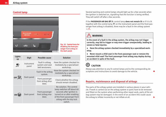
Control lamp
Fig. 18 Control lamp fordisabling the front pas-senger front airbag onthe dash panel
Lightsup
Digit Possible cause Solution
Instrument
panel
Fault in airbagsystem and seatbelt tensioners.
Have the system checked im-mediately by a specialised
workshop.
OFF Dash panel
Fault in the airbagsystem.
Have the system checked im-mediately by a specialised
workshop.
Front passengerfront airbag disa-
bled.
Check whether the airbagshould remain disabled.
ON Dash panelFront passengerfront airbag ena-
bled.
No solution. The controllamp switches off about 60
seconds after ignition isturned on or after enablingof the front passenger front
airbag with the key lockswitch.
Several warning and control lamps should light up for a few seconds whenthe ignition is switched on, signalling that the function is being verified.They will switch off after a few seconds.
If the PASSENGER AIR BAG control lamp does not remain lit or if it is littogether with the control lamp on the instrument panel and the front pas-senger front airbag is disabled, there may be a fault in the airbag system⇒ .
WARNING
In the event of a fault in the airbag system, the airbag may not triggercorrectly, may fail to trigger or may even trigger unexpectedly, leading tosevere or fatal injuries.
● Have the airbag system checked immediately by a specialised work-shop.
● Never mount a child seat in the front passenger seat or remove themounted child seat! The front passenger front airbag may deploy duringan accident in spite of the fault.
CAUTIONAlways pay attention to any lit control lamps and to the corresponding de-scriptions and instructions to avoid damage to the vehicle.
Repairs, maintenance and disposal of airbags
The parts of the airbag system are installed in various places in your vehi-cle. If work is carried out on the airbag system or parts have to be removedand fitted on the system when performing other repair work, parts of the air-bag system may be damaged. In the event of an accident this could causethe airbag to inflate incorrectly or not inflate at all.

35Airbag system
The relevant safety requirements must be observed when the vehicle orcomponents of the airbag are scrapped. Specialised workshops and vehicledisposal centres are familiar with these requirements.
WARNING
● If repairs are not carried out by a professional, or if the airbags areused incorrectly, the risk of severe or fatal injuries is increased. The air-bags may fail to inflate, or could inflate in the wrong circumstances.
● Do not cover or stick anything on the steering wheel hub or the sur-face of the airbag unit on the passenger side of the dash panel, and donot obstruct or modify them in any way.
● It is important not to attach any objects such as cup holders or tele-phone mountings to the surfaces covering the airbag units.
● To clean the steering wheel or dash panel, you may use only a dry or awater-moistened cloth. Never clean the dash panel and the airbag mod-ule surface with cleaners containing solvents. Solvents cause the surfaceto become porous. If the airbag triggered, plastic parts could become de-tached and cause injuries.
● Never attempt to repair, adjust, remove or install parts of the airbagsystem.
● Any work on the airbag system or removal and installation of the air-bag components for other repairs (such as repairs to the steering wheel)should be performed only by a specialised workshop. Specialised work-shops have the necessary tools, repair information and qualified person-nel.
● We strongly recommend you to go to a specialised workshop for allwork on the airbag system.
● Never attempt to alter the front bumper or the body.
● The airbags provide protection for just one accident; replace themonce they have deployed.
For the sake of the environmentThe airbags, which are a special type of waste, must be disposed of throughan authorised service, because they contain pyrotechnic elements.
Safety First Operating instructions Practical Tips Technical specifications

36 Airbag system
Front airbags
Description of front airbags
The airbag system is not a substitute for the seat belts.
Fig. 19 Driver airbag lo-cated in steering wheel
Fig. 20 Front passengerairbag located in dashpanel
The front airbag for the driver is located in the steering wheel ⇒ Fig. 19 andthe airbag for the front passenger is located in the dash panel ⇒ Fig. 20. Air-bags are identified by the word “AIRBAG”.
In conjunction with the seat belts, the front airbag system gives the frontoccupants additional protection for the head and chest in the event of a se-vere frontal collision ⇒ page 38, Safety notes on the front airbag system.
In addition to their normal function of restraining the occupants, the seatbelts also hold the driver and front passenger in a position where the air-bags can provide maximum protection in a frontal collision.
The airbag system is not a substitute for seat belts, but it is an integral partof the vehicle's overall passive safety system. Please bear in mind that theairbag system can only work effectively when the vehicle occupants arewearing their seat belts correctly and have adjusted the head restraintsproperly. Therefore, it is most important to wear the seat belts at all times,not only because this is required by law in most countries, but also for yoursafety ⇒ page 20, Brief introduction.
The main parts of the front airbag system are:
● an electronic control and monitoring system (control unit)
● the two front airbags (airbag with gas generator) for the driver and frontpassenger
● a control lamp in the dash panel
The airbag system operation is monitored electronically. The airbag controllamp will light up for a few seconds every time the ignition is switched on(self-diagnosis).
There is a fault in the system if the control lamp :
● does not light up when the ignition is switched on
● turns off after 4 seconds after the ignition is switched on
● turns off and then lights up again after the ignition is switched on
● lights up or flashes while the vehicle is moving

37Airbag system
The front airbag system will not be triggered if:
● the ignition is switched off
● there is a minor frontal collision
● there is a side collision
● there is a rear-end collision
● the vehicle turns over
WARNING
● The seat belts and airbags can only provide maximum protection ifthe occupants are seated correctly ⇒ page 10, Sitting position for vehicleoccupants.
● If a fault has occurred in the airbag system, have the system checkedimmediately by a specialised workshop. Otherwise, during a frontal colli-sion the system may fail to trigger, or not trigger correctly.
Operation of front airbags
Inflated airbags reduce the risk of injuries to the head orchest.
Fig. 21 Inflated front air-bags
The airbag system is designed so that the airbags for the driver and frontpassenger are triggered in a severe frontal collision.
In certain types of accident the front, curtain and side airbags may be trig-gered together.
When the system is triggered, the airbags fill with a propellant gas and de-ploy in front of the driver and front passenger ⇒ Fig. 21. The fully deployedairbags cushion the forward movement of the front occupants and help toreduce the risk of injury to the head and the upper part of the body.
The special design of the airbag allows the controlled escape of the propel-lant gas when an occupant puts pressure on the bag. Thus, the head andchest are surrounded and protected by the airbag. After the collision, theairbag deflates sufficiently to allow visibility.
Safety First Operating instructions Practical Tips Technical specifications

38 Airbag system
The airbags deploy extremely rapidly, within thousandths of a second, toprovide additional protection in the event of an accident. A fine dust maydevelop when the airbag deploys. This is normal and it is not an indicationof fire in the vehicle.
Airbag covers when the frontal airbags are triggered
Fig. 22 Airbag covers reacting when the front airbags are triggered
The airbag covers fold out of the steering wheel or dash panel when thedriver and front passenger airbags are triggered ⇒ Fig. 22. The airbag cov-ers remain connected to the steering wheel or the dash panel.
Safety notes on the front airbag system
If you use airbags correctly, they can considerably reducethe risk of injury in many kinds of accident.
WARNING
● It is important for the driver and front passenger to keep a distance ofat least 25 cm from the steering wheel and dash panel. If the minimumdistance is not observed then the airbags do not correctly protect the ve-hicle occupants; risk of fatal injuries! In addition, the front seats andhead restraints must always be positioned correctly for the height of theoccupant.
● If you are not wearing a seat belt, if you lean forward or to the sidewhile travelling or assume an incorrect sitting position, there is a sub-stantially increased risk of injury. This increased risk of injury will be fur-ther increased if you are struck by an inflating airbag.
● Never let a child travel on the front seat without an appropriate re-straint system. If the airbag is triggered in an accident, children can sus-tain serious or fatal injuries from the airbag as it inflates ⇒ page 48.
● The deployment space between the front passengers and the airbagsmust not in any case be occupied by other passenger, pets and objects.
● The airbags provide protection for just one accident; replace themonce they have deployed.
● It is also important not to attach any objects such as cup holders ortelephone mountings to the surfaces covering the airbag units.
● Do not attempt to modify components of the airbag system in anyway.

39Airbag system
Knee airbag*
Fig. 23 On the driverside: location of the kneeairbag
Fig. 24 On the driverside: Radius of action ofthe knee airbag
The knee airbag is located on the driver side below the dash panel⇒ Fig. 23. Airbags are identified by the word “AIRBAG”.
The area framed in red ⇒ Fig. 24 is covered by the knee airbag when it isdeployed (deployment area). Therefore, objects should never be placed ormounted in these areas.
WARNING
The airbag is deployed at high speed in fractions of a second.
● The knee airbag is deployed in front of the driver's knees. Alwayskeep the deployment areas of the knee airbags free.
● Never not fix objects to the cover or in the deployment area of theknee airbag.
● Adjust the driver seat so that there is a distance of at least 10 cm (4inches) between your knees and the location of the knee airbag. If youphysical constitution prevents you from meeting these requirements,make sure you contact a specialised workshop.
Safety First Operating instructions Practical Tips Technical specifications

40 Airbag system
Side airbags*
Description of side airbags
The airbag system is not a substitute for the seat belts.
Fig. 25 Side airbag indriver seat
The side airbags are located in the backrest cushions of the driver seat⇒ Fig. 25 and the front passenger seat as well as in the rear seats*. The lo-cations are identified by the text “AIRBAG” in the upper region of the backr-ests.
Together with the seat belts, the side airbag system gives the front seat oc-cupants additional protection for the upper body in the event of a severeside collision ⇒ page 42, Safety notes on the operation of the side airbagsystem.
In a side collision, the side airbags reduce the risk of injury to passengerson the front seats to the areas of the body facing the impact. In addition totheir normal function of protecting the occupants in a collision, the seatbelts also hold the passengers in the front seats and the outer rear seats ina position where the side airbags can provide maximum protection.
The airbag system is not a substitute for seat belts, but it is an integral partof the vehicle's overall passive safety system. Please bear in mind that theairbag system can only work effectively when the occupants are wearingtheir seat belts. Therefore, it is most important to wear the seat belts at alltimes, not only because this is required by law in most countries, but alsofor your safety ⇒ page 20, Brief introduction.
The side airbag system will not be triggered if:
● the ignition is switched off
● there is a minor side collision
● there is a frontal collision
● there is a rear-end collision
● the vehicle turns over
The main parts of the airbag system are:
● an electronic control and monitoring system (control unit)
● the side airbags in the sides of the backrests of the front and rear seats
● a control lamp in the dash panel
The airbag system operation is monitored electronically. The airbag controllamp will light up for approx. 4 seconds every time the ignition is switchedon (self-diagnosis).
WARNING
● In a side-on collision the side airbags will not work if the sensors donot correctly measure the pressure increase on the interior of the doors,due to air escaping through the areas with holes or openings in the doorpanel.
● Never drive the vehicle if the interior panels have been removed.
● Never drive if the interior door panels have been removed or if thepanels have not been correctly fitted.

41Airbag system
WARNING (Continued)
● Never drive the vehicle if the loudspeakers in the door panels havebeen removed, unless the holes left by the loudspeakers have been cor-rectly closed.
● Always check that the openings are closed or covered if loudspeakersor other equipment are fitted in the interior door panels.
● Any work carried out to the doors should be made in an authorisedspecialised workshop.
● The seat belts and airbags can only provide maximum protection ifthe occupants are seated correctly ⇒ page 10, Sitting position for vehicleoccupants.
● If a fault has occurred in the airbag system, have the system checkedimmediately by a specialised workshop. Otherwise, during a side colli-sion, the system may fail to trigger, or not trigger correctly.
Operation of side airbags
Inflated airbags can reduce the risk of head or chest injuryin many side impact collisions.
Fig. 26 Illustration ofcompletely inflated sideairbags on left side of ve-hicle
In some side collisions, the side airbag is triggered on the impact side ofthe vehicle ⇒ Fig. 26.
In certain types of accident the front, curtain and side airbags may be trig-gered together.
When the system is triggered, the airbag is filled with propellant gas.
The airbags deploy extremely rapidly, within thousandths of a second, toprovide additional protection in the event of an accident. A fine dust maydevelop when the airbag deploys. This is normal and it is not an indicationof fire in the vehicle.
The fully deployed airbags cushion the movement of the occupants of thefront seats and the outer rear seats and help to reduce the risk of injury tothe upper body.
Safety First Operating instructions Practical Tips Technical specifications

42 Airbag system
The special design of the airbag allows the controlled escape of the propel-lant gas when an occupant puts pressure on the bag. Thus, the head andchest are surrounded and protected by the airbag.
Safety notes on the operation of the side airbag system
If airbags are used correctly, they can considerably reducethe risk of injury in side impact collisions.
WARNING
● If you do not wear a seat belt, if you lean forward, or are not seatedcorrectly while the vehicle is in motion, you are at a greater risk of injuryif the side airbag system is triggered in an accident.
● In order for the side airbags to provide their maximum protection, theprescribed sitting position must always be maintained with seat beltsfastened while travelling.
● Occupants of the outer seats must never carry any objects or pets inthe deployment space between them and the airbags, or allow childrenor other passengers to travel in this position. It is also important not toattach any accessories (such as cup holders) to the doors. This would im-pair the protection offered by the side airbags.
● The built-in coat hooks should be used only for lightweight clothing.Do not leave any heavy or sharp-edged objects in the pockets.
● Great forces, such as hard blows or kicks, must not be exerted uponthe backrest bolster because the system may be damaged. In this case,the side airbags would not be triggered.
WARNING (Continued)
● Under no circumstances should protective covers be fitted over seatswith side airbags unless the covers have been approved for use in yourvehicle. Because the airbag deploys from the side of the backrest, theuse of conventional seat covers would obstruct the side airbag, seriouslyreducing the airbag's effectiveness.
● Any damage to the original seat upholstery or around the seams ofthe side airbag units must be repaired immediately by a specialisedworkshop.
● The airbags provide protection for just one accident; replace themonce they have deployed.
● When children assume an incorrect sitting position, they exposethemselves to an increased risk of injury in the event of an accident. Thisis particularly the case if the child is travelling on the front passengerseat and the airbag system is triggered in an accident; this could havecritical consequences including serious injury or death ⇒ page 48.
● Any work on the side airbag system or removal and installation of theairbag components for other repairs (such as removal of the front seat)should only be performed by a specialised workshop. Otherwise, faultsmay occur during the airbag system operation.
● Do not attempt to modify components of the airbag system in anyway.
● The side and head airbags are managed through sensors located inthe interior of the front doors. To ensure the correct operation of the sideand head airbags neither the doors nor the door panels should be modi-fied in any way (e.g. fitting loudspeakers). If the front door is damaged,the airbag system may not work correctly. All work carried out on thefront door must be done in a specialised workshop.

43Airbag system
Curtain airbags
Description of curtain airbags
The airbag system is not a substitute for the seat belts.
Fig. 27 Location of curtain airbags
The curtain airbags are located on both sides in the interior above the doors⇒ Fig. 27 and are identified with the text “AIRBAG”.
In conjunction with the seat belts, the curtain airbag system gives the vehi-cle occupants additional protection for the head and upper body in theevent of a severe side collision ⇒ page 44, Safety notes on the operationof the curtain airbag system.
The airbag system is not a substitute for seat belts, but it is an integral partof the vehicle's overall passive safety system. Please bear in mind that theairbag system can only work effectively when the vehicle occupants arewearing their seat belts correctly and have adjusted the head restraintsproperly. Therefore, it is most important to wear the seat belts at all times,
not only because this is required by law in most countries, but also for yoursafety ⇒ page 20, Brief introduction.
The main parts of the curtain airbag system are:
● an electronic control and monitoring system (control unit)
● the curtain airbags (airbags with gas generator) for the driver, front pas-senger and passengers on the rear seats
● a control lamp in the dash panel
The airbag system operation is monitored electronically.
The curtain airbag system will not be triggered if:
● the ignition is switched off
● there is a frontal collision
● there is a rear-end collision
● the vehicle turns over
● there is a minor side collision
WARNING
If a fault has occurred in the airbag system, have the system checked im-mediately by a specialised workshop. Otherwise there is a danger thatduring a collision, the system may fail to trigger, or not trigger correctly.
Operation of curtain airbags
Fully inflated airbags reduce the risk of head or chest injuryin a side collision.
During some side collisions the curtain airbag is triggered on the impactside of the vehicle ⇒ Fig. 27.
Safety First Operating instructions Practical Tips Technical specifications
44 Airbag system
In certain types of accident the front, side and curtain airbags may be trig-gered together.
When the system is triggered, the airbag is filled with propellant gas. In theprocess, the curtain airbag covers the side windows and door pillars.
The airbags deploy extremely rapidly, within thousandths of a second, toprovide additional protection in the event of an accident. A fine dust maydevelop when the airbag deploys. This is normal and it is not an indicationof fire in the vehicle.
The fully deployed airbags cushion the movement of the front occupantsand help to reduce the risk of injury to the upper body.
The special design of the airbag allows the controlled escape of the propel-lant gas when an occupant puts pressure on the bag. Thus, the head andchest are surrounded and protected by the airbag.
Safety notes on the operation of the curtain airbag system
If you use airbags correctly, they can considerably reducethe risk of injury in many kinds of accident.
WARNING
● In order for the side airbags to provide their maximum protection, theprescribed sitting position must always be maintained with seat beltsfastened while travelling.
● For safety reasons, the curtain airbag must be disabled in those vehi-cles fitted with a screen dividing the interior of the vehicle. See a Techni-cal Service to make this adjustment.
WARNING (Continued)
● There must be no other persons, animals or objects between the oc-cupants of the outer seats and the deployment space of the curtain air-bags so that the curtain airbag can deploy without restriction and pro-vide the greatest possible protection. Therefore, sun blinds which havenot been expressly approved for use in your vehicle may not be attachedto the side windows.
● The built-in coat hooks should be used only for lightweight clothing.Do not leave any heavy or sharp-edged objects in the pockets. Please, donot hang the clothes on coat hangers.
● The airbags provide protection for just one accident; replace themonce they have deployed.
● Any work on the curtain airbag system or removal and installation ofthe airbag components for other repairs (such as removal of the roof lin-ing) should only be performed by a specialised workshop. Otherwise,faults may occur during the airbag system operation.
● Do not attempt to modify components of the airbag system in anyway.
● The side and head airbags are managed through sensors located inthe interior of the front doors. To ensure the correct operation of the sideand head airbags neither the doors nor the door panels should be modi-fied in any way (e.g. fitting loudspeakers). If the front door is damaged,the airbag system may not work correctly. All work carried out on thefront door must be done in a specialised workshop.

45Airbag system
Deactivating airbags
Deactivating airbags
The deactivation of airbags corresponds only to certain cases, i.e. if:
● a child seat is required in the front passenger seat with the child facingin the opposite direction to the direction of travel (in some countries, due todivergent legal requirements, facing in the direction of travel) ⇒ page 50;
● despite the driver seat being in the correct position, a minimum dis-tance of 25 cm cannot be maintained between the centre of the steeringwheel and the driver's torso.
● installation of special devices is required in the steering wheel area dueto a physical disability.
● if you have special seats installed (e.g. an orthopaedic seat without sideairbag).
The front passenger front airbag can be disabled using the switch⇒ page 46.
We recommend that you contact an authorised SEAT dealer for the disablingof other airbags.
Airbag system control
The airbag system availability is controlled electronically, regardless ofwhether an airbag is disabled.
If an airbag was disabled using a diagnostics system:
● the airbag system warning lamp lights up after switching on the igni-tion for about 4 seconds, and then flashes for about 12 seconds
If the airbag has been disabled with the airbag switch on the side of thedash panel:
● the airbag control lamp will light up for about 4 seconds after the ig-nition is switched on.
● The airbag is disabled, signalled with the warning lamp whichlights up with the word placed in the centre part of thedash panel ⇒ Fig. 28.
Note● Respect the current legislation in your country regarding the deactiva-tion of airbags
● At your authorised SEAT dealer you can find information on which vehi-cle airbags can be deactivated.
Safety First Operating instructions Practical Tips Technical specifications

46 Airbag system
Front passenger front airbag switch
Fig. 28 Front passengerfront airbag switch
Fig. 29 Warning lamp fordisabling the front pas-senger airbag
The switch disables only the front passenger front airbag.
Disabling the airbag
– Switch the ignition off.
– Open the glove compartment on the front passenger side.
– Insert the key into the slot of the switch for deactivating thefront passenger airbag ⇒ Fig. 28. About 3/4 of the key shouldenter, as far as it will go.
– Then turn the key gently to the OFF position. Do not force it ifyou feel resistance, and make sure you have inserted the keyfully.
– Check, with the ignition switched on, that the control lamplights up ⇒ Fig. 29 with the word inthe centre part of the dash panel.
Switching on the airbag
– Switch the ignition off.
– Insert the key into the slot of the switch for deactivating thefront passenger airbag ⇒ Fig. 28. About 3/4 of the key shouldenter, as far as it will go.
– Then turn the key gently to the ON position. Do not force it if youfeel resistance, and make sure you have inserted the key fully.
– Close the passenger side storage compartment.
– Check, with the ignition switched on, that the control lamp ⇒ Fig. 29 does not light up, with the word in the centre part of the dash panel.
– The warning lamp is illuminated for 60 seconds in the cen-tre part of the dash panel.

47Airbag system
Control lamp with the word (front passenger airbagdisabled)
If the front passenger front airbag is disabled, after switching on the igni-tion, the control lamp will light up for several seconds, then it will switch offfor about 1 s and then switch on again.
If the control lamp is flashing, there is a fault in the disabling of the airbagsystem ⇒ . Please go immediately to an Official Service.
WARNING
● The driver of the vehicle is responsible for disabling or switching onthe airbag.
● Always switch off the ignition before disabling the front passengerairbag! Failure to do so could result in a fault in the airbag deactivationsystem.
● Never leave the key in the airbag deactivation switch as it could getdamaged or activate or deactivate the airbag during driving.
● If the control lamp (airbag deactivated) flashes, the front pas-senger front airbag will not trigger in the event of an accident! Have thesystem immediately checked by an Official Service.
Safety First Operating instructions Practical Tips Technical specifications

48 Child safety
Child safety
Brief introduction
Introduction
Statistics show that children are generally safer on the rearseat than on the front passenger seat.
For safety reasons we recommend that children under 12 years of age travelon the rear seats. Depending on their age, height and weight, children trav-elling on the rear seat must use a child seat or a seat belt. For safety rea-sons, the child seat should be installed in the centre of the rear seat or be-hind the front passenger seat.
The physical laws involved and the forces acting in a collision apply also tochildren ⇒ page 22.
But unlike adults, children do not have fully developed muscle and bonestructures. This means that children are subject to a greater risk of injury.
To reduce this risk, children must always use special child restraint systemswhen travelling in the vehicle.
We recommend the use of child safety products from the SEAT Original Ac-cessories Programme, which includes systems for all ages made by“Peke”1).
These systems have been especially designed and approved, complyingwith the ECE-R44. regulation.
Follow the manufacturer's instructions and observe any statutory require-ments when installing and using child seats. Always read and note⇒ page 48.
We recommend you to always include the manufacturer's Child Seat Instruc-tion Manual together with the on-board documentation.
Safety notes on using child seats
Proper use of child seats substantially reduces the risk of in-jury in an accident!
As the driver, you are responsible for any children you transport in your vehi-cle.
● Protect your children by properly using the appropriate child seats⇒ page 50.
● Always ensure that the seat belt is properly positioned according to theinstructions provided by the manufacturer of the child seat.
● When travelling, do not allow children to distract you from traffic.
● Take breaks regularly during long trips. Take a break at least every twohours.
1) Not for all countries

49Child safety
WARNING
● Never install a child seat facing backwards on the front passengerseat unless the front passenger front airbag has been disabled. Risk ofpotentially fatal injuries to the child! However, if it is necessary, in excep-tional cases, to transport a child in the front passenger seat, the frontpassenger front airbag must always be disabled ⇒ page 45. If the pas-senger seat has a height adjustment option, move it to the highest, mostupright position. If you have a fixed seat, do not install any child restraintsystem in this location.
● For those vehicles that do not include a key lock switch to deactivatethe airbag, the vehicle must be taken to a Technical Service.
● All vehicle occupants, especially children, must assume the propersitting position and be properly belted in while travelling.
● Never hold children or babies on your lap, this can result in potential-ly fatal injuries to the child!
● Never allow a child to be transported in a vehicle without being prop-erly secured, or to stand up or kneel on a seat while travelling. In an acci-dent, the child could be flung through the vehicle, causing possibly fatalinjuries to themselves and to the other vehicle occupants.
● If children assume an improper sitting position when the vehicle ismoving, they expose themselves to greater risk of injury in the event of asudden braking manoeuvre or in an accident. This is particularly impor-tant if the child is travelling on the front passenger seat and the airbagsystem is triggered in an accident; as this could cause serious injury oreven death.
● A suitable child seat can protect your child!
● Never leave an unsupervised child alone on a child seat or in the vehi-cle.
● Depending on weather conditions, it may become extremely hot orcold inside the vehicle. This can be fatal.
WARNING (Continued)
● Children who are less than 1.5 metres tall must not wear a normalseat belt without a child seat, as this could cause injuries to the abdomi-nal and neck areas during a sudden braking manoeuvre or in an accident.
● Do not allow the seat belt to become twisted or jammed, or to rub onany sharp edges.
● Incorrectly worn seat belts can cause injuries even in a minor colli-sion or in sudden braking manoeuvres.
● The seat belt provides maximum protection only when the seat belt isproperly positioned ⇒ page 26, Seat belts.
● Only one child may occupy a child seat ⇒ page 50, Child seats.
Safety First Operating instructions Practical Tips Technical specifications

50 Child safety
Child seats
Categorisation of child seats into groups
Use only child seats that are officially approved and suitablefor the child.
Child seats are subject to the regulation ECE-R 44. ECE-R stands for: Eco-nomic Commission for Europe Regulation
The child seats are grouped into 5 categories:
Group 0: up to 10 kg
Group 0+: up to 13 kg
Group 1: from 9 to 18 kg
Group 2: from 15 to 25 kg
Group 3: from 22 to 36 kg
Child seats that have been tested and approved under the ECE R44 stand-ard bear the test mark on the seat (the letter E in a circle with the test num-ber below it).
Group 0 and 0+ child seats
A suitable child seat and a correctly adjusted seat belt canhelp you to protect your child.
Fig. 30 A group 0 rear-facing child seat fitted onthe rear seat
Group 0: Infants up to 10 kg (approx. 9 months) must travel in the directionopposite to travel ⇒ Fig. 30.
Group 0+: Infants up to 13 kg (approx. 18 months) must travel in the direc-tion opposite to travel ⇒ Fig. 30.
Follow the manufacturer's instructions and observe any statutory require-ments when installing and using child seats.
We recommend you to always include the manufacturer's Child Seat Instruc-tion Manual together with the on-board documentation.
SEAT recommends the use of child seats from the Original Accessories cata-logue. These child seats have been designed and tested for use in SEAT ve-hicles. You can find the right child seat for your model and age group atSEAT dealers.

51Child safety
WARNING
Read and always observe information and warnings concerning the useof child seats ⇒ page 48.
Group 1 child seats
A suitable child seat and a correctly adjusted seat belt canhelp you to protect your child.
Fig. 31 A category 1 for-ward-facing child seat fit-ted on the rear seat
Babies and young children between 9 and 18 kg can travel in the directionof travel or in the reverse, depending on the seat type. For safety reasons itis recommended that the child is transported in the direction opposite totravel for as long as possible. Consult the instruction manual of the childseat manufacturer for possible installation options.
Follow the manufacturer's instructions and observe any statutory require-ments when installing and using child seats.
We recommend you to always include the manufacturer's Child Seat Instruc-tion Manual together with the on-board documentation.
SEAT recommends the use of child seats from the Original Accessories cata-logue. These child seats have been designed and tested for use in SEAT ve-hicles. You can find the right child seat for your model and age group atSEAT dealers.
WARNING
Read and always observe information and warnings concerning the useof child seats ⇒ page 48.
Group 2 and 3 child seats
A suitable child seat and a correctly adjusted seat belt canhelp you to protect your child.
Fig. 32 Forward-facingchild seat installed onrear seat
Safety First Operating instructions Practical Tips Technical specifications

52 Child safety
The child seats in groups 2 and 3 must be mounted in the direction ofmovement and using the vehicle’s seatbelt.
Follow the manufacturer's instructions and observe any statutory require-ments when installing and using child seats.
We recommend you to always include the manufacturer's Child Seat Instruc-tion Manual together with the on-board documentation.
SEAT recommends the use of child seats from the Original Accessories cata-logue. These child seats have been designed and tested for use in SEAT ve-hicles. You can find the right child seat for your model and age group atSEAT dealers.
Group 2 child seats
Children under 7 years of age weighing between 15 and 25 kg are best pro-tected by group 2 child seats together with properly adjusted seat belts.
Group 3 child seats
Children over 7 years of age weighing between 22 and 36 kg but less than1.5 metres tall are best protected by child seats with head restraints togeth-er with properly worn seat belts ⇒ Fig. 32.
WARNING
● The shoulder part of the seat belt must lie approximately on the cen-tre of the shoulder, never across the neck or the arm. The seat belt mustlie close to the upper part of the body. The lap belt part must lie acrossthe pelvis, not across the stomach, and always fit closely. Pull the belttight if necessary to take up any slack ⇒ page 26, Seat belts.
● Read and always observe information and warnings concerning theuse of child seats ⇒ page 48.

53Child safety
Securing child seats
Ways to secure a child seat
A child seat can be secured differently on the rear seat andon the front passenger seat.
Fig. 33 On the rear seats: figure A shows the basic child restraint system mountingusing lower retaining rings and the upper retaining strap figure B shows the child re-straint system mounting using the vehicle seat belt
You can secure a child seat to the rear seat or front passenger seat in thefollowing ways:
● Child seats in groups 0 to 3 can be secured with a seat belt.
● Child seats in groups 0, 0+ and 1 with the ISOFIX and Top Tether* sys-tems can be secured without using the seatbelt, thanks to the ISOFIX andTop Tether* securing rings ⇒ page 55.
● During installation of some models of group I, II and III child seats in therear seat, difficulty may arise in mounting the seat given that it comes intocontact with the head restraint. In this case adjust the height of the head
restraint or remove it from the seat following the instructions in the corre-sponding chapter ⇒ page 131. Once you remove the child seat, replace thehead restraint in its original position.
Securing the child seat using the seat belt
The seat belt may be used to secure universal type child seats to the vehicleseats marked with a U in the table below.
● If the front passenger seat lacks a height adjustment, child seats cannotbe mounted is this location.
Mass groupSeating position
Front passengerseat
Rear side seat Rear centralseat
Group 0to 10 kg
U* U U
Group 0+to 13 kg
U* U U
Group I9 to 18 kg
U* U U
Group II15 to 25 kg
U* U U
Group III22 to 36 kg
U* U U
Suitable for universal restraint systems for use in this mass group.
Only compatible for models with adjustable seat height. Place seat inthe backmost highest position possible.
U:
*:
Safety First Operating instructions Practical Tips Technical specifications

54 Child safety
WARNING
● When travelling, children must be secured in the vehicle with a re-straint system suitable for age, weight and size.
● Never install a child seat facing backwards on the front passengerseat unless the front passenger airbag has been disabled. This couldcause fatal injuries to the child! However, if, in exceptional cases, it isnecessary to transport a child in the front passenger seat, the front pas-senger airbag ⇒ page 45 must always be disabled and the seat adjustedto its backmost highest position, where possible.
● Read and always observe information and warnings concerning theuse of child seats ⇒ page 48.

55Child safety
Child seats fastened with the “ISOFIX” and Top Tether* system
Child seats with the “ISOFIX” and Toptether* system can be secured quickly, easily and safely on the rear outer seats.
Two “ISOFIX” retaining rings are fitted on each rear seat. In some vehicles,the rings are secured to the seat frame and, in others, they are secured tothe rear floor. The access to the ISOFIX rings is between the rear seat back-rest and the seat cushioning. The Top Tether* anchors are located at therear of the backrests of the rear seats (behind the seat backrest or in theluggage compartment).
To understand the compatibility of the "ISOFIX" systems in the vehicle, con-sult the table below.
● The allowed body weight for the child seat or information regarding sizeA to F is indicated on the label on the child seat with certification universalor semi-universal.
Mass group Size class Electrical equipment Mounting directionVehicle Isofix positions
Rear side seats
Baby carrierF ISO/L1 Backward-facing X
G ISO/L2 Backward-facing X
Group 0 to 10 kg E ISO/R1 Backward-facing IU
Group 0+ to 13 kg
E ISO/R1 Backward-facing IU
D ISO/R2 Backward-facing IU
C ISO/R3 Backward-facing IU
Group I 9 to 18 kg
D ISO/R2 Backward-facing IU
C ISO/R3 Backward-facing IU
B ISO/F2 Forward-facing IU
B1 ISO/F2X Forward-facing IU
A ISO/F3 Forward-facing IU
Group II 15 to 25 kg --- --- Forward-facing ---
Group III 22 to 36 kg --- --- Forward-facing ---
Suitable for ISOFIX universal child restraint systems approved for use inthis mass group
ISOFIX position not suitable for ISOFIX child restraint systems for thismass group or size class
IU:
X:
Safety First Operating instructions Practical Tips Technical specifications

56 Child safety
WARNING
● The securing rings are designed only for use with ISOFIX and TopTether* child seats.
● Never secure child seats that do not have the ISOFIX and Top Tether*system, retaining belts or other objects to the securing rings – this couldresult in potentially fatal injuries to the child!
● Ensure that the child seat is secured correctly using the “ISOFIX” andTop Tether* securing rings.
ISOFIX child seat mounting system
Fig. 34 ISOFIX securingrings
When removing or fitting the child seat, please be sure to followthe manufacturer's instructions.
– Remove the protective caps of the “ISOFIX” rings by placing afinger in the hole and pulling up ⇒ Fig. 34.
– Press the child seat onto the ISOFIX retaining rings until thechild seat can be heard to engage securely. If the child seat isequipped with Toptether* anchor points, secure it to the corre-spondent ring. Follow the manufacturer's instructions.
– Do a test by pulling both sides of the child seat to ensure that itis properly anchored.
Child seats with the ISOFIX and Top Tether* attachment system are availablefrom Technical Services.
Top Tether retainer straps*
Some child restraint seats have a third Top Tether anchoringpoint, apart from both “ISOFIX” anchoring points, which al-low better child retention.
Fig. 35 Position of theTop Tether rings on theback of the rear seat

57Child safety
Child seats with the Top Tether system come with a strap for securing theseat to the vehicle anchor point, located at the back of the rear seat back-rest.
The objective of the retainer strap is to reduce forward movements of thechild seat in a crash, helping reduce the risk of injuries to the head from hit-ting the inside of the vehicle.
Using the Top Tether in rear-facing mounted seats
Currently, there are very few rear-facing child safety seats that have TopTether. Please carefully read and follow the seat manufacturer instructionsto learn the proper way to install the Top Tether strap.
Fitting the Top Tether child restraint to the anchoring point
Fig. 36 Retainer strap:correct adjustment andfitting
Securing the Top Tether child restraint to the anchor point situatedon the rear of the backrest
– Pull out the fastening belt of the child restraint seat accordingto the manufacturer's instructions.
– Guide the Top Tether fastening belt under the rear seat head re-straint ⇒ Fig. 36 (lift the head restraint where necessary).
– Slide the belt so that the Top Tether belt of the child restraintseat is correctly secured to the anchor on the back of the rearseat.
– Firmly tighten the Top Tether belt following the child restraintseat manufacturer's instructions.
Releasing the retaining strap
– Release the retainer strap in line with the instructions given bythe child safety seat manufacturer.
– Push the lock and release it from the anchoring support.
WARNING
An undue installation of the safety seat will increase the risk of injury inthe event of a crash.
● Never tie the retainer strap to a hook in the luggage compartment.
● Never secure or tie luggage or other items to the lower anchorages(ISOFIX) or the upper ones (Top Tether).
Safety First Operating instructions Practical Tips Technical specifications

58 Controls and displays
Fig. 37 Controls and displays

59Controls and displays
Operating instructions
Controls and displays
Overview
Door handle
Central locking switch . . . . . . . . . . . . . . . . . . . . . . . . . . . . . . . . . . . . . 94
Electric control to adjust exterior mirrors . . . . . . . . . . . . . . . . . . . . 125
Air outlets . . . . . . . . . . . . . . . . . . . . . . . . . . . . . . . . . . . . . . . . . . . . . . . . 160
Control lever for:
– Turn signals and main beam headlights . . . . . . . . . . . . . . . . . 110
– Lane Assist . . . . . . . . . . . . . . . . . . . . . . . . . . . . . . . . . . . . . . . . . . . . . 207
– Main beam assist . . . . . . . . . . . . . . . . . . . . . . . . . . . . . . . . . . . . . . . 114
– Cruise control system (CCS) . . . . . . . . . . . . . . . . . . . . . . . . . . . . . 184
Depending on equipment fitted:
– Lever for cruise control . . . . . . . . . . . . . . . . . . . . . . . . . . . . . . . . . . 184
Steering wheel with horn and
– Driver airbag . . . . . . . . . . . . . . . . . . . . . . . . . . . . . . . . . . . . . . . . . . . 36
– On-board computer controls . . . . . . . . . . . . . . . . . . . . . . . . . . . . 73
– Controls for radio, telephone, navigation and speech dia-logue system ⇒ Booklet Radio
– Paddle levers for tiptronic gearshift (automatic gearbox) . . 178
Instrument panel . . . . . . . . . . . . . . . . . . . . . . . . . . . . . . . . . . . . . . . . . . 61
Control lever for:
– Windscreen wipers and washer . . . . . . . . . . . . . . . . . . . . . . . . . . 120
– Wipe and wash system . . . . . . . . . . . . . . . . . . . . . . . . . . . . . . . . . 120
– On-board computer . . . . . . . . . . . . . . . . . . . . . . . . . . . . . . . . . . . . . 73
1
2
3
4
5
6
7
8
9
Depending on equipment fitted: Radio or display for EasyConnect (navigation, radio, TV/video) . . . . . . . . . . . . . . . . . . . . . . 79
Depending on the equipment, buttons for:
– SEAT driving modes . . . . . . . . . . . . . . . . . . . . . . . . . . . . . . . . . . . . . 211
– Start-Stop system . . . . . . . . . . . . . . . . . . . . . . . . . . . . . . . . . . . . . . . 169
– Park assist system . . . . . . . . . . . . . . . . . . . . . . . . . . . . . . . . . . . . . . 217
– Hazard warning lights . . . . . . . . . . . . . . . . . . . . . . . . . . . . . . . . . . 113
– Airbag off display . . . . . . . . . . . . . . . . . . . . . . . . . . . . . . . . . . . . . . . 46
Glove box with (depending on equipment): . . . . . . . . . . . . . . . . . 134
– CD player* and/or SD card* ⇒ Booklet Radio
– Multimedia interface* ⇒ Booklet Radio
Tyre pressure switch . . . . . . . . . . . . . . . . . . . . . . . . . . . . . . . . . . . . . . . 216
Front passenger airbag switch . . . . . . . . . . . . . . . . . . . . . . . . . . . . . 46
Front passenger airbag . . . . . . . . . . . . . . . . . . . . . . . . . . . . . . . . . . . . 36
Passenger seat heating control . . . . . . . . . . . . . . . . . . . . . . . . . . . . 130
Storage compartment
Depending on gearbox fitted, gear lever or selector lever for:
– manual gearbox . . . . . . . . . . . . . . . . . . . . . . . . . . . . . . . . . . . . . . . . 172
– automatic gearbox . . . . . . . . . . . . . . . . . . . . . . . . . . . . . . . . . . . . . . 173
Depending on the equipment, controls for:
– Heating and ventilation system or manual air conditioner . 158, 157
– Automatic air conditioner . . . . . . . . . . . . . . . . . . . . . . . . . . . . . . . 154
Parking brake . . . . . . . . . . . . . . . . . . . . . . . . . . . . . . . . . . . . . . . . . . . . . 166
Driver seat heating control . . . . . . . . . . . . . . . . . . . . . . . . . . . . . . . . . 130
10
11
12
13
14
15
16
17
18
19
20
21
Safety First Operating instructions Practical Tips Technical specifications

60 Controls and displays
Ignition lock . . . . . . . . . . . . . . . . . . . . . . . . . . . . . . . . . . . . . . . . . . . . . . 162
Knee airbag . . . . . . . . . . . . . . . . . . . . . . . . . . . . . . . . . . . . . . . . . . . . . . . 39
Adjustable steering column . . . . . . . . . . . . . . . . . . . . . . . . . . . . . . . . 162
Storage compartment
Bonnet lock release . . . . . . . . . . . . . . . . . . . . . . . . . . . . . . . . . . . . . . . 252
Headlight range control . . . . . . . . . . . . . . . . . . . . . . . . . . . . . . . . . . . 117
Light switch . . . . . . . . . . . . . . . . . . . . . . . . . . . . . . . . . . . . . . . . . . . . . . . 109
Electric windows . . . . . . . . . . . . . . . . . . . . . . . . . . . . . . . . . . . . . . . . . . 102
Note● Some of the equipment listed in this section is only fitted on certainmodels or are optional extras.
● A separate instruction manual is enclosed if the vehicle is equippedwith a factory-fitted radio, CD player, AUX IN connection, or navigation sys-tem.
● The arrangement of switches and controls on right-hand drive models*may be slightly different from the layout shown in ⇒ page 58. However, thesymbols used to identify the controls are the same.
22
23
24
25
26
27
28
29

61Instruments and warning/control lamps
Instruments and warning/control lamps
Instruments
Introduction
Additional information and warnings:
● Control and warning lamps ⇒ page 69
● SEAT information system
● Easy Connect system
● Gear engaged display (automatic gearbox) ⇒ page 173.
● Instructions for inspection intervals ⇒ Booklet Maintenance Programme
WARNING
Any distraction may lead to an accident, with the risk of injury.
● Do not operate the instrument panel controls when driving.
View of instrument panel
Fig. 38 Instrument panel, on dash panel
Details of the instruments ⇒ Fig. 38:
Rev counter (with the engine running, in hundreds of revolutions perminute).
The beginning of the red zone of the rev counter indicates the maxi-mum speed in any gear after running-in and with the engine hot. How-ever, it is advisable to change up a gear or move the selector lever to D(or lift your foot off the accelerator) before the needle reaches the redzone ⇒ .
Engine coolant temperature display ⇒ page 257.
Displays on the screen ⇒ page 62.
Adjuster button and display ⇒ page 67
Speedometer.
Fuel reserve display ⇒ page 248.
1
2
3
4
5
6
Safety First Operating instructions Practical Tips Technical specifications

62 Instruments and warning/control lamps
CAUTION● To prevent damage to the engine, the rev counter needle should only re-main in the red zone for a short period of time.
● When the engine is cold, avoid high revs and heavy acceleration and donot make the engine work hard.
For the sake of the environmentChanging up a gear in time reduces fuel consumption and noise.
Displays on screen
Fig. 39 A: bonnet open; B: rear lid open; C: front left door open; D: rear right dooropen (5-door vehicles only)
A variety of information can be viewed on the instrument panel display⇒ Fig. 38 3 depending on the vehicle equipment:
● Bonnet, rear lid and doors open ⇒ Fig. 39.
● Information and warning texts
● Mileage
● Time
● Navigation instructions
● Outside temperature
● Compass
● Selector lever position ⇒ page 173
● Recommended gear (manual gearbox) ⇒ page 68
● Multifunction display (MFD) and menus with different setting options⇒ page 73.
● Service interval display ⇒ page 65
● Second speed display ⇒ page 73
● Speed warning function ⇒ page 168
● Start-Stop system status display ⇒ page 169
● Identifying letters on engine (MKB)
Bonnet, rear lid and doors open
When the ignition is switched on or when driving, the bonnet, rear lid ordoors that are open will be indicated on the instrument panel display, and ifit should be the case, this will also be indicated audibly. The display mayvary according to the type of instrument panel fitted.

63Instruments and warning/control lamps
Illustration Key to ⇒ Fig. 39 See
A Do not continue driving!The bonnet is open or is not properlyclosed.
⇒ page 251
B Do not continue driving!The rear lid is open or is not properlyclosed.
⇒ page 100
C, D Do not continue driving!A vehicle door is open or is not properlyclosed.
⇒ page 87
Warning and information texts
The system runs a check on certain components and functions when the ig-nition is switched on and while the vehicle is moving. Faults in the opera-tion are displayed on the screen using red and yellow symbols and messag-es on the instrument panel display (⇒ page 69) and, in some cases, withaudible warnings. The display may vary according to the type of instrumentpanel fitted.
Type of mes-sage
Symbolcolour
Description
Priority 1warning.
Red
Symbol flashing or lit; partly combined withaudible warnings. Stop the vehicle! It is dangerous ⇒ !Check the function that is faulty and repair it.If necessary, request assistance from special-ised personnel.
Priority 2warning.
Yellow
Symbol flashing or lit; partly combined withaudible warnings.A faulty function, or fluids which are belowthe correct levels may cause damage to thevehicle! ⇒ Check the faulty function as soon as possible.If necessary, request assistance from special-ised personnel.
Informativetext.
–Information relating to different vehicle pro-cesses.
Mileage
The odometer registers the total distance travelled by the car.
The odometer (trip) shows the distance travelled since the last odometer re-set. The last digit of the trip recorder indicates distances of 100 metres orone tenths of a mile.
● Briefly press the button ⇒ Fig. 38 4 to reset the trip recorder to 0.
● Keep the button 4 pressed for about 3 seconds and the previous valuewill be displayed.
Time
● To set the time, keep the button ⇒ Fig. 38 4 pressed for more than 3seconds to select the hour or minute display.
● To continue setting the time, press the upper or lower part of the button4 . Hold button down to scroll through the numbers quickly.
● Press the button 4 again in order to finish setting the time.
Safety First Operating instructions Practical Tips Technical specifications

64 Instruments and warning/control lamps
The time can also be set via the key and Setup function button in theEasy Connect system ⇒ page 79.
Outside temperature display
When the outside temperature is below +4 °C (+39 °F), the symbol “ice crys-tal” (warning of risk of freezing) is also displayed next to the temperature.At first this symbol flashes and then it remains lit until the outside tempera-ture rises above +6 °C (+43 °F) ⇒ .
When the vehicle is at a standstill or when travelling at very low speeds, thetemperature displayed may be higher than the true outside temperature asa result of the heat produced by the engine.
The temperatures measured range from -40 °C to +50 °C (-40 °F to +122 °F).
Compass
With the ignition on and the navigation system on, the cardinal point corre-sponding to the direction of travel of the vehicle is displayed on the instru-ment panel.
Selector lever positions
The selected gear is displayed on the side of the selector lever and on theinstrument panel display. In positions D and S, and with the Tiptronic, thecorresponding gear is also displayed.
Recommended gear (manual gearbox)
The recommended gear in order to save fuel is displayed on the instrumentpanel while you are driving ⇒ page 68.
Second speed display (mph or km/h)
In addition to the speedometer, the speed can also be displayed in a differ-ent unit of measurement (in miles or in km per hour).
This option cannot be deactivated in models destined for countries in whichthe second speed must always be visible.
The second speed display can be adjusted in the Easy Connect system viathe key and the Setup function button ⇒ page 79.
Speed warning
When the speed setting is exceeded, this will be indicated on the instru-ment panel display. This is very useful, for example when using winter tyresthat are not designed for driving at the maximum speed of the vehicle⇒ page 168.
The speed warning settings can be adjusted in the Easy Connect system viathe key and the Setup function button ⇒ page 79.
Start/Stop operating display
Updated information relating to the status is displayed on the instrumentpanel ⇒ page 169.
Identifying letters on engine (MKB)
Hold the button ⇒ Fig. 38 4 down for more than 15 seconds to display theidentifying letters of the vehicle engine (MKB). To do this, the ignition mustbe switched on and the engine switched off.
WARNING
If the warning lamps and messages are ignored, the vehicle may stall intraffic, or may cause accidents and severe injuries.
● Never ignore the warning lamps or text messages.
● Stop the vehicle safely as soon as possible.
● A faulty vehicle represents a risk of accident for the driver and for oth-er road users. If necessary, switch on the hazard warning lamps and putout the warning triangle to advise other drivers.
● Park the vehicle away from the traffic, ensuring that there are no easi-ly inflammable materials under the vehicle which could come into contactwith the exhaust system (e.g. dry grass, fuel).

65Instruments and warning/control lamps
WARNING
Although the outside temperature is above freezing, some roads andbridges may be frozen.
● At an outside temperature of above +4 °C (+39 °F), even when the“ice crystal” is not visible, there may still be ice on the road.
● Never rely on the outside temperature indicator!
CAUTIONFailure to heed the control lamps and text messages when they appear mayresult in faults in the vehicle.
Note● Different versions of the instrument panel are available and thereforethe versions and instructions on the display may vary. In the case of dis-plays without warning or information texts, faults are indicated exclusivelyby the warning lamps.
● Depending on the equipment, some settings and instructions can alsobe carried out in the Easy Connect system.
● When several warnings are active at the same time, the symbols areshown successively for a few seconds. The symbols will stay on until thefault is rectified.
Service interval display
The service interval indication appears on the instrument panel display⇒ Fig. 38 3 .
SEAT distinguishes between services with engine oil change (e.g. Oilchange service) and services without engine oil change (e.g. Inspection).
In vehicles with Services established by time or mileage, the service inter-vals are already pre-defined.
In vehicles with LongLife Service, the intervals are determined individually.Technical progress has made it possible to considerably reduce servicing re-quirements. The technology used by SEAT ensures that your vehicle onlyhas an Oil Change Service when it is necessary. To establish when the OilChange Service is due (max. 2 years), the vehicle's conditions of use andindividual driving styles are considered. The service pre-warning first ap-pears 20 days before the date established for the corresponding service.The kilometres remaining until the next service are always rounded up tothe nearest 100 km (miles) and the remaining time is given in completedays. The current service message cannot be viewed until 500 km (miles)after the last service. Prior to this only lines are visible on the display.
Inspection reminder
When the Service date is approaching, when the ignition is switched on aService reminder is displayed.
In vehicles without text messages, a spanner is displayed on the instrumentpanel with a figure given in km. The number of kilometres shown is themaximum number that may be driven until the next service. After a few sec-onds, the display mode changes. A clock symbol appears and the numberof days until the next service appointment is due.
In vehicles with text messages, Service in --- km (miles) or --- days is dis-played on the instrument panel.
Service due
After the service date, an audible warning is given when the ignition isswitched on and the spanner displayed on the screen flashes for a few sec-onds . In vehicles with text messages, Service in --- km or --- days is dis-played on the instrument panel.
Reading a service notification
With the ignition switched on, the engine off and the vehicle at a standstill,the current service notification can be read:
Safety First Operating instructions Practical Tips Technical specifications

66 Instruments and warning/control lamps
Press and hold the button ⇒ Fig. 38 4 for more than 5 seconds to consultthe service message.
When the service date has past, a minus sign is displayed in front of thenumber of kilometres or days. In vehicles with text messages the followingis displayed: Service --- km (miles) or --- days ago.
The time can also be set via the key and Setup function button in theEasy Connect system ⇒ page 79.
The service interval display is reset
If the service was not carried out by a SEAT dealership, the display can bereset as follows:
● To reset the service interval display, turn the ignition off and press andhold the button ⇒ Fig. 38 4 .
● Switch the ignition back on.
● Release the button 4 and press the button 4 again for the next 20seconds.
Note● The service message disappears after a few seconds, when the engine isstarted or when OK/RESET is pressed on the windscreen wiper lever, or OK
on the multifunction steering wheel.
● In vehicles with the LongLife system in which the battery has been dis-connected for a long period of time, it is not possible to calculate the dateof the next service. Therefore the service interval display may not be correct.In this case, please check the maximum permitted service intervals ⇒ Book-let Maintenance Programme.
Rev counter
The rev counter indicates the number of engine revolutionsper minute.
Together with the gear-change indicator, the rev counter offers you the pos-sibility of using the engine of your vehicle at a suitable speed.
The start of the red zone on the dial indicates the maximum engine speedwhich may be used briefly when the engine is warm and after it has beenrun in properly. Before reaching this range, you should change to a highergear for vehicles with a manual gearbox or for automatic gearboxes put theselector lever in “D” or take your foot off the accelerator pedal.
We recommend that you avoid high revs and that you follow the recommen-dations on the gear-change indicator. Consult the additional information in⇒ page 68, Gear-change indicator.
CAUTIONNever allow the rev counter needle 1 ⇒ Fig. 38 to go into the red zone onthe scale for more than a very brief period, otherwise, there is a risk of en-gine damage.
For the sake of the environmentChanging up a gear early will help you to save fuel and minimise enginenoise.

67Instruments and warning/control lamps
Trip recorder
Fig. 40 Instrument pan-el: Odometer and resetbutton
The distance covered is displayed in “kilometres” or miles “m”. It is possi-ble to change the measurement units (kilometres “km”/miles “m”) in theradio/Easy Connect*. Please refer to the Easy Connect* Instruction Manualfor more details.
Odometer/trip recorder
The odometer shows the total distance covered by the vehicle.
The trip recorder shows the distance that has been travelled since it waslast reset. It is used to measure short trips. The last digit of the trip recorderindicates distances of 100 metres or tenths of a mile.
The trip recorder can be set to zero by pressing 0.0/SET ⇒ Fig. 40.
Fault display
If there is a fault in the instrument panel, the letters DEF will appear in thetrip recorder display. Have the fault repaired immediately, as far as is possi-ble.
Fuel level
The display 6 ⇒ Fig. 38 only works when the ignition is switched on. Whenthe display reaches the reserve mark, the lower diode lights up in red andthe control lamp appears ⇒ page 248. When the fuel level is very low,the lower diode flashes in red.
The distance to empty fuel level is displayed on the instrument panel 3
⇒ Fig. 38.
The capacity of the fuel tank of your vehicle is given in the Technical datasection ⇒ page 323.
In natural gas engines
The yellow warning lamp lights up when both fuel types (petrol and natu-ral gas) have reached reserve level.
The green control lamp comes on when the vehicle is working with naturalgas.
The green control lamp switches off when the natural gas is exhausted.The engine changes to operate with petrol.
Thing to note: If the vehicle is left parked for a long time immediately afterrefuelling, the natural gas level indicator may not accurately indicate thesame level shown after refuelling when the vehicle is started up again. Thisis not due to a leak in the system, but to a drop in pressure in the gas tankfor technical reasons after a cooling phase immediately after refuelling.
CAUTIONNever run the fuel tank completely dry. An irregular fuel supply could causemisfiring. In this way the unburned fuel can reach the exhaust system,which could cause the catalytic converter to overheat resulting in damage.
Safety First Operating instructions Practical Tips Technical specifications

68 Instruments and warning/control lamps
Coolant temperature gauge
For vehicles with no coolant temperature gauge, a control lamp appears forhigh coolant temperatures ⇒ page 257. Take into account the ⇒ .
The coolant temperature gauge 2 ⇒ Fig. 38 only works when the ignition isswitched on. In order to avoid engine damage, please read the followingnotes for the different temperature ranges.
Engine cold
If only the diodes in the lower part of the scale light up, this indicates thatthe engine has not yet reached operating temperature. Avoid high revs andheavy acceleration and do not make the engine work hard.
Normal temperature
If in normal operations, the diodes light up until the central zone, it meansthat the engine has reached operating temperature. At high outside temper-atures and when making the engine work hard, the diodes may continuelighting up and reach the upper zone. This is no cause for concern, providedthe control lamp does not light up on the instrument panel digital dis-play.
Heat range
When the diodes light up in the upper area of the display and the controllamp appears on the instrument panel display, the coolant temperatureis excessive ⇒ page 257.
CAUTION● To ensure a long useful life for the engine, avoid high revs, driving athigh speed and making the engine work hard for approx. the first 15 mi-nutes when the engine is cold. The phase until the engine is warm also de-pends on the outside temperature. If necessary, use the engine oil tempera-ture* as a guide ⇒ page 77
● Additional lights and other accessories in front of the air inlet reduce thecooling effect of the coolant. At high outside temperatures and high engineloads, there is a risk of the engine overheating.
● The front spoiler also ensures proper distribution of the cooling air whenthe vehicle is moving. If the spoiler is damaged this can reduce the coolingeffect, which could cause the engine to overheat. Seek specialist assis-tance.
Gear-change indicator
This additional indicator function can help to save fuel.
Fig. 41 Instrument pan-el: Gear-change indicator(manual gearbox)
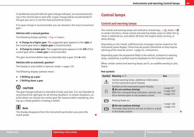
69Instruments and warning/control lamps
To familiarise yourself with the gear-change indicator, we recommend driv-ing in the normal way to start with. A gear change will be recommended ifthe gear you are in is not the most economical choice.
If no gear-change is recommended, you are already in the most economicalgear.
Vehicles with a manual gearbox
The following display symbols ⇒ Fig. 41 mean:
● Change to a higher gear: The suggested gear appears to the right ofthe current gear when a higher gear is recommended.
● Change to a lower gear: The suggested gear appears to the left of thecurrent gear when a lower gear is recommended.
The gear recommendation may occasionally skip a gear (2nd 4th).
Vehicles with an automatic gearbox*
The display is only visible in tiptronic mode ⇒ page 178
The following display symbols mean:
● Shifting up a gear
● Shifting down a gear
CAUTIONThe gear-change indicator is intended to help save fuel. It is not intended torecommend the right gear for all driving situations. In certain situations, on-ly the driver can choose the correct gear (for instance when overtaking, driv-ing up a steep gradient or towing a trailer).
NoteThe display disappears from the instrument panel when you press theclutch pedal.
Control lamps
Control and warning lamps
The control and warning lamps are indicators of warnings, ⇒ , faults ⇒ or certain functions. Some control and warning lamps come on when the ig-nition is switched on, and switch off when the engine starts running, orwhile driving.
Depending on the model, additional text messages may be viewed on theinstrument panel display. These may be purely informative or they may beadvising of the need for action ⇒ page 61, Instruments.
Depending upon the equipment fitted in the vehicle, instead of a warninglamp, sometimes a symbol may be displayed on the instrument panel.
When certain control and warning lamps are lit, an audible warning is alsoheard.
Red symbols
Symbol Meaning ⇒ See
Central warning lamp: additional informationon the instrument panel display
–
Symbol on the instrument panel display: Do not continue driving!With the corresponding indication: door(s), rearlid or bonnet open or not properly closed.
⇒ page 87⇒ page 100⇒ page 251
Parking brake on.⇒ page 166⇒ page 224
Do not continue driving!The brake fluid level is too low or there is a faultin the brake system.
Safety First Operating instructions Practical Tips Technical specifications

70 Instruments and warning/control lamps
Symbol Meaning ⇒ See
Lit up on instrument panel display:a)
Do not continue driving!Engine coolant level too low, coolant tempera-ture too highFlashing on the instrument panel display:a)
Fault in the engine coolant system.
⇒ page 257
On the instrument panel display:a)
Do not continue driving!Engine oil pressure too low.
⇒ page 253
Lit up or flashing: Do not continue driving!Fault in the steering.
⇒ page 225
Driver or passenger has not fastened seat belt. ⇒ page 20
Use the foot brake!
On the instrument panel display:a)
Fault in the battery.⇒ page 260
a) Colour presentation on instrument panel with colour display.
Yellow symbols
Symbol Meaning ⇒ See
Central warning lamp: additional informationon the instrument panel display
–
Front brake pads worn.
⇒ page 222
lights: Fault in the ESC, or disconnectioncaused by the system.
flashes: ESC or ASR activated.
ASR manually deactivated.
ABS faulty or does not work.
Rear fog light switched on. ⇒ page 109
On the instrument panel display:a)
Driving light totally or partially faulty.⇒ page 293
On the instrument panel display:a)
Fault in the cornering light system.⇒ page 109
Lights up or flashes: Fault in the emission con-trol system.
⇒ page 230
lights: pre-ignition of diesel engine.
flashes: Fault in engine management.
Fault in engine management.
On the instrument panel display:a)
Diesel particulate filter blocked.
Lights up or flashes: Fault in the steering sys-tem.
⇒ page 162
Tyre pressure too low, or fault in the tyre pres-sure monitoring system.
⇒ page 214

71Instruments and warning/control lamps
Symbol Meaning ⇒ See
On the instrument panel display:a)
Level of windscreen washer fluid too low.⇒ page 120
Fuel tank almost empty. ⇒ page 248
Flashing on the instrument panel display:a)
Fault in the oil level detection. Control manual-ly. ⇒ page 253
Lit up on the instrument panel display:a)
Engine oil level insufficient.
Fault in airbag system and seat belt tensioners.
⇒ page 31OFF Front passenger front airbag is off (PASSENGERAIRBAG ).
ON Front passenger front airbag is on (PASSENGERAIRBAG ).
Lane Assist is switched on, but not active. ⇒ page 207
On the instrument panel display:a)
Fault in the gearbox.⇒ page 182
a) Colour presentation on instrument panel with colour display.
Other control lamps
Symbol Meaning ⇒ See
Left or right turn signal. ⇒ page 109
Hazard warning lights on. ⇒ page 113
Trailer turn signals ⇒ page 234
Symbol Meaning ⇒ See
lights: Press the foot brake!flashes: The selector lever locking button hasnot engaged.
⇒ page 173
The vehicle is stopped by engine braking.
lights: Cruise control operating.
⇒ page 184lights: Speed limiter switched on and active.
flashes: The speed set by the speed limiter hasbeen exceeded.
Lane Assist is switched on and active. ⇒ page 207
Main beam on or flasher on.⇒ page 109
On the instrument panel display:Light Assist switched on.
On the instrument panel display:Immobiliser active.
On the instrument panel display:Service interval display.
⇒ page 65
On the instrument panel display:Mobile telephone is connected via Bluetooth tothe original telephone device. ⇒ Book-
let BluetoothSystem
On the instrument panel display:Mobile telephone battery charge meter. Availa-ble only for pre-installed factory-fitted devices.
On the instrument panel display:Ice warning. The outside temperature is lowerthan +4 °C (+39 °F).
⇒ page 64
Safety First Operating instructions Practical Tips Technical specifications

72 Instruments and warning/control lamps
Symbol Meaning ⇒ See
On the instrument panel display:Start-Stop system active.
⇒ page 169On the instrument panel display:Start-Stop system not available.
On the instrument panel display:Engine running.
WARNING
If the warning lamps and messages are ignored, the vehicle may stall intraffic, or may cause accidents and severe injuries.
● Never ignore the warning lamps or text messages.
● Stop the vehicle safely as soon as possible.
● Park the vehicle away from the traffic, ensuring that there are no easi-ly inflammable materials under the vehicle which could come into contactwith the exhaust system (e.g. dry grass, fuel).
● A faulty vehicle represents a risk of accident for the driver and for oth-er road users. If necessary, switch on the hazard warning lamps and putout the warning triangle to advise other drivers.
● Before opening the bonnet, switch off the engine and allow it to cool.
● In any vehicle, the engine compartment is a hazardous area and couldcause severe injuries ⇒ page 251.
CAUTIONFailure to heed the control lamps and text messages when they appear mayresult in faults in the vehicle.

73Driver information system
Driver information system
Information system
Introduction
With the ignition switched on, it is possible to read the different functions ofthe display by scrolling through the menus.
In vehicles with multifunction steering wheel, the multifunction display canonly be operated with the multifunction steering wheel buttons.
The number of menus displayed on the instrument panel will vary accordingto the vehicle electronics and equipment.
A specialised workshop will be able to programme or modify additionalfunctions, according to the vehicle equipment. SEAT recommends visiting aSEAT Official Service.
Some menu options can only be read when the vehicle is at a standstill.
As long as a priority 1 warning is displayed, it will not be possible to readthe menus. Some warning messages can be confirmed and made to disap-pear with the windscreen wiper lever button or the multifunction steeringwheel button.
Additional information and warnings:
● Easy Connect system ⇒ page 79
● Driver assistance systems ⇒ page 184
● Radio or navigation system ⇒ Booklet Radio or ⇒ Booklet Navigationsystem
WARNING
Any distraction may lead to an accident, with the risk of injury.
● Do not read the instrument panel display menus when driving.
Overview of the menu structure
Driving data ⇒ page 75■ Vehicle status■ MFD from departure■ MFD from refuelling■ MFD total calculation
Assist systems ⇒ table on page 75
■ Activate/deactivate Lane Assist■ Reverse (optional)
Navigation ⇒ Booklet Navigation system
Audio ⇒ Booklet Radio or ⇒ Booklet Navigation system
Telephone ⇒ Booklet Bluetooth system
Vehicle ⇒ table on page 75
Safety First Operating instructions Practical Tips Technical specifications
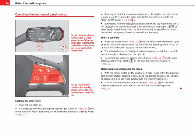
74 Driver information system
Operating the instrument panel menus
Fig. 42 Vehicles withoutmultifunction steeringwheel: Button 1 on thewindscreen wiper lever toconfirm the menu optionsand rocker switch 2 tochange menu
Fig. 43 Right side ofmultifunction steeringwheel: buttons to accessthe instrument panel me-nus
Enabling the main menu
● Switch the ignition on.
● If a message or vehicle pictogram appears, press button ⇒ Fig. 42 1 onthe windscreen wiper lever or button on the multifunction steering wheel⇒ Fig. 43.
● If managed from the windscreen wiper lever: To display the main menu⇒ page 75 or to return to the main menu from another menu, hold therocker switch down ⇒ Fig. 42 2 .
● If managed from the multifunction steering wheel: the main menu list isnot displayed. To move down each point on the main menu, press orpress several times ⇒ Fig. 43 (if the vehicle is equipped with a basicinstrument dash panel, these buttons will not function).
Select a submenu
● Press the rocker switch ⇒ Fig. 42 2 on the windscreen wiper lever up ordown or turn the thumbwheel of the multifunction steering wheel ⇒ Fig. 43until the desired option appears marked on the menu.
● The selected option is displayed between two horizontal lines. In addi-tion, a triangle is displayed on the right: .
● To consult the submenu option, press button ⇒ Fig. 42 1 on the wind-screen wiper lever or button on the multifunction steering wheel⇒ Fig. 43.
Making changes according to the menu
● With the rocker switch on the windscreen wiper lever or the thumbwheelof the multifunction steering wheel, make the desired changes. To increaseor decrease the values more quickly, turn the thumbwheel faster.
● Mark or confirm the selection with button ⇒ Fig. 42 1 on the wind-screen wiper lever or button on the multifunction steering wheel⇒ Fig. 43.

75Driver information system
Button for the driving assistance systems*
Fig. 44 On the turn sig-nal and main beam head-light lever: button for thedriving assistance sys-tems
With the turn signal and main beam headlight lever button, you can activateor deactivate the driver assistance systems displayed in the Assist systemsmenu ⇒ page 184.
Activate or deactivate a driver assistance system
● Briefly press the button ⇒ Fig. 44 in the direction of the arrow to openthe menu Assist systems.
● Select the driver assistance system and activate or deactivate it⇒ page 74. A mark indicates that driver assistance system is switched on.
Menu
Menu effect See
Driving dataInformation and possible configurations ofthe multifunction display (MFD).
⇒ page 75⇒ page 79
Assist sys-tems
Information and possible configurations ofthe driver assistance systems.
⇒ page 79
Menu effect See
Navigation
Information instructions from the activatednavigation system: When a route guidanceis activated, the turning arrows and prox-imity bars are displayed. The appearance issimilar to the Easy Connect system.If the route guidance is not activated, thedirection of travel (compass) and the nameof the street along which you are drivingare shown.
⇒ Booklet Navi-gation system
AudioStation display on the radio.Track name on the CD.Track name in Media mode.
⇒ Booklet Radioor⇒ Booklet Navi-gation system
TelephoneInformation and possible configurations ofthe mobile phone preinstallation.
⇒ Booklet Blue-tooth System
Vehicle sta-tus
Display of the current warning or informa-tion texts and other system components,depending on the equipment
⇒ page 79
Driving data
The MFD (multifunction display) shows different values for the journey andthe consumption.
Changing between display modes on the MFD
● In vehicles without multifunction steering wheel: Press the rocker switch on the windscreen wiper lever ⇒ Fig. 42.
● Vehicles with a multifunction steering wheel: turn the thumbwheel.
Safety First Operating instructions Practical Tips Technical specifications

76 Driver information system
Multifunction display memory
The multifunction display is equipped with three memories that work auto-matically: MFD from departure, MFD from refuelling, MFD total calculation.On the screen display, you can read which memory is currently displayed.
To change between memories with the ignition on and the memory shown,press the button on the windscreen wiper lever or you can alsochange between memories using the button on the multifunction steer-ing wheel.
Menu effect
MFD from de-parture
Display and storage of the values for the journey and theconsumption from when the ignition is switched on towhen it is switched off.If the journey is continued in less than 2 hours after the ig-nition is switched off, the new data is added to the data al-ready stored in the memory. The memory will automaticallybe deleted if the journey is interrupted for more than twohours.
MFD from re-fuelling
Display and storage of the values for the journey and theconsumption. By refuelling, the memory will be erased au-tomatically.
MFD total cal-culation
The memory records the values for a specific number ofpartial trips, up to a total of 19 hours and 59 minutes or 99hours and 59 minutes, or 1999.9 km (or miles) or 9999 km(or miles), depending on the model of instrument panel.On reaching either of these limitsa), the memory is auto-matically erased and starts to count from 0 again.
a) It varies according to the type of instrument panel fitted.
Erasing a memory manually
● Select the memory that you wish to erase.
● Press and hold the button on the windscreen wiper lever or thebutton on the multifunction steering wheel for about 2 seconds.
Personalising the displays
In the Easy Connect system you can adjust which of the possible displays ofthe MFD can be shown on the instrument panel display with the button and the function button Setup ⇒ page 79.
Displays
Menu effect
Current fuel con-sumption
The current fuel consumption display operates through-out the journey, in litres/100 km; and with the enginerunning and the vehicle stopped, in litres/hour.
Average fuel con-sumption
After turning on the ignition, average fuel consumptionin litres/100 km will be shown after travelling approxi-mately 100 metres. Otherwise horizontal lines are dis-played. The value shown is updated approximately ev-ery 5 seconds.
Operating range
Approximate distance in km that can still be travelledwith the fuel remaining in the tank, assuming the samestyle of driving is maintained. This is calculated usingthe current fuel consumption.
Journey durationThis indicates the hours (h) and minutes (min) sincethe ignition was switched on.
Distance coveredDistance covered in km (m) after switching on the igni-tion.
CNG quality
Whenever you refuel, an automatic check is run on thequality of the natural gas and is displayed after the ig-nition is switched on. The indication is given as a per-centage of between 70 % and 100 %. The greater thepercentage, the lower the consumption.
Average speed
The average speed will be shown after a distance of ap-proximately 100 metres has been travelled. Otherwisehorizontal lines are displayed. The value shown is up-dated approximately every 5 seconds.
Digital display ofspeed
Current speed displayed in digital format.

77Driver information system
Displays
Menu effect
Speed warning at--- km/h or Speedwarning at --- mph
If the stored speed is exceeded (between 30 - 250 km/h, or 19 - 155 mph), an audible warning is given to-gether with a visual warning.
Oil temperature Updated engine oil temperature digital display
Coolant tempera-ture gauge
Digital display of the current temperature of the liquidcoolant.
Storing a speed for the speed warning
● Select the display Speed warning at --- km/h (--- mph)
● Press the button on the windscreen wiper lever or the button on the multifunction steering wheel to store the current speed and activatethe warning.
● If necessary, adjust the desired speed within 5 seconds using the rockerswitch on the windscreen wiper lever or by turning the thumbwheel onthe multifunction steering wheel. Next, press the button or againor wait several seconds. The speed is stored and the warning activated.
● To deactivate it press the button or the button . The storedspeed is deleted.
Assist systems submenu
Assist systemsmenu
effect
Lane Assist* Switching the Lane Assist system on or off ⇒ page 210.
Tiredness detec-tion*
Switching the tiredness detection on or off (pause recom-mendation) ⇒ page 213.
Engine oil temperature display
Vehicles without multifunction steering wheel
– To display the temperature of the engine oil, press the rockerswitch ⇒ Fig. 42 2 until the main menu appears. Enter intoJourney data. With the button 2 move to the oil temperaturegauge.
Vehicles with multifunction steering wheel
– To display the engine oil temperature, enter the submenu Jour-ney data and turn the thumbwheel until the oil temperature dis-play appears.
The engine reaches its operating temperature when in normal driving condi-tions, the oil temperature is between 80 °C (180 °F) and 120 °C (250 °F). Ifthe engine is required to work hard and the outside temperature is high, theengine oil temperature can increase. This does not present any problem aslong as the warning lamps ⇒ page 69 or ⇒ page 70 do not appear onthe display.
Additional electrical appliances
– Operation with the windscreen wiper lever*: Press the rockerswitch ⇒ Fig. 42 2 until the main menu appears. Enter into thesection Journey data. With the rocker switch, move to the displayConvenience appliances.
– Operation with the multifunction steering wheel*: Move withthe buttons 1 or 2 to Journey data and enter with OK. Turn thethumbwheel to the right until the Convenience appliances dis-play appears.
Safety First Operating instructions Practical Tips Technical specifications

78 Driver information system
In addition, a scale will inform you of the current sum of all the additionalappliances.
Saving tips
Tips on how to save fuel will be displayed in certain conditions thatcontribute to increased consumption. Following these tips couldreduce the fuel consumption of your vehicle. The displays appearautomatically and will only be shown with the efficiency pro-gramme. After a time, the saving tips will disappear automatically.
– If you wish to hide a saving tip immediately after it appears,press any button on the windscreen wiper lever*/multifunctionsteering wheel*.
Note● If you hide a saving tip, it will reappear after you switch the ignition onagain.
● The saving tips do not appear in all situations, but rather with a largeseparation of time.
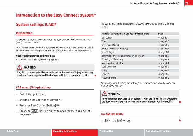
79Introduction to the Easy Connect system*
Introduction to the Easy Connect system*
System settings (CAR)*
Introduction
To select the settings menus, press the Easy Connect button and theSetup function button.
The actual number of menus available and the name of the various optionsin these menus will depend on the vehicle’s electronics and equipment.
Additional information and warnings:
● Driver assistance systems ⇒ page 184
WARNING
Any distraction may lead to an accident, with the risk of injury. Operatingthe Easy Connect system while driving could distract you from traffic.
CAR menu (Setup) settings
– Switch the ignition on.
– Switch on the Easy Connect system.
– Press the Easy Connect button .
– Press the Setup function button to open the main Vehicle set-tings menu.
Pressing the menu button will always take you to the last menuused.
Function buttons in the vehicle’s settings menu Page
ESC system ⇒ page 79
Tyres ⇒ page 80
Driver assistance ⇒ page 80
Parking and manoeuvring ⇒ page 81
Vehicle lights ⇒ page 82
Rear vision mirrors and windscreen wipers ⇒ page 82
Opening and closing ⇒ page 83
Multifunction display ⇒ page 83
Date and time ⇒ page 84
Units ⇒ page 84
Service ⇒ page 85
Factory settings ⇒ page 85
Any changes made using the settings menus are automatically saved onclosing those menus.
WARNING
Any distraction may lead to an accident, with the risk of injury. Operatingthe Easy Connect system while driving could distract you from traffic.
ESC System menu
– Switch the ignition on.
Safety First Operating instructions Practical Tips Technical specifications

80 Introduction to the Easy Connect system*
– Switch on the Easy Connect system.
– Press the Easy Connect button .
– Press the Setup function button.
– Press the ESC System function button to make changes to theElectronic Stability Programme (ESC).
When the menu appears, choose the desired option.
Pressing the menu button will always take you to the last menu used.
Menu Submenu Possible setting Description
Vehicle settings –Activation of theElectronic StabilityProgramme (ESC)
⇒ page 222
Any changes made using the settings menus are automatically saved onclosing those menus.
WARNING
Any distraction may lead to an accident, with the risk of injury. Operatingthe Easy Connect system while driving could distract you from traffic.
Tyre Settings menu
– Switch the ignition on.
– Switch on the Easy Connect system.
– Press the Easy Connect button .
– Press the Setup function button.
– Press the Tyre button to open the Tyre settings menu.
When the function button check box is activated , the function is active.
Pressing the menu button will always take you to the last menu used.
Menu Submenu Possible setting Description
Tyre settings
Tyre pressuremonitoring
Tyre pressure storing(Calibration)
⇒ page 214
Winter tyres
Speed warning acti-vation and deactiva-tionChange the speedwarning value
⇒ page 168
Any changes made using the settings menus are automatically saved onclosing those menus.
WARNING
Any distraction may lead to an accident, with the risk of injury. Operatingthe Easy Connect system while driving could distract you from traffic.
Driver Assistance settings menu
– Switch the ignition on.
– Switch on the Easy Connect system.
– Press the Easy Connect button .
– Press the Setup function button.

81Introduction to the Easy Connect system*
– Press the Driver assistance function button to open the Driver as-sistance settings menu.
When the function button check box is activated , the function is active.
Pressing the menu button will always take you to the last menu used.
Menu Submenu Possible setting Description
Driver Assis-tance settings
ACC (AdaptiveCruise Control)
Activation and deacti-vation of the settingthat takes the last dis-tance selected.The following functionscan be set:– Driving programme– Time distance to thevehicle ahead (level ofdistance)
⇒ page 189
Front Assist
The following functionscan be switched onand off:– Monitoring System– Pre-warning– Distance warningdisplay
⇒ page 202
City emergencybraking function
City emergency brak-ing function switch onand off
Lane Assist (sys-tem warning you ifyou leave the lane)
Lane Centring Assist⇒ page 207Activation/deactiva-
tion
Tiredness detec-tion
Activation/deactiva-tion
⇒ page 213
Any changes made using the settings menus are automatically saved onclosing those menus.
WARNING
Any distraction may lead to an accident, with the risk of injury. Operatingthe Easy Connect system while driving could distract you from traffic.
Parking and Manoeuvring Settings menu
– Switch the ignition on.
– Switch on the Easy Connect system.
– Press the Easy Connect button .
– Press the Setup function button.
– Press the Parking and manoeuvring button to open the Parking andmanoeuvring settings menu.
When the function button check box is activated , the function is active.
Pressing the menu button will always take you to the last menu used.
Menu Submenu Possible setting Description
Parking and Ma-noeuvring set-tings
ParkPilot
Automatically acti-vate, front volume,front sound settings,rear volume, rearsound settings, ad-just volume.
⇒ page 217
Any changes made using the settings menus are automatically saved onclosing those menus.
Safety First Operating instructions Practical Tips Technical specifications
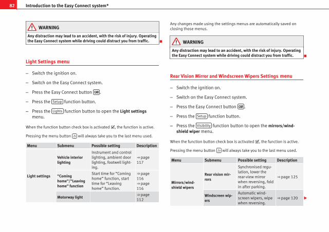
82 Introduction to the Easy Connect system*
WARNING
Any distraction may lead to an accident, with the risk of injury. Operatingthe Easy Connect system while driving could distract you from traffic.
Light Settings menu
– Switch the ignition on.
– Switch on the Easy Connect system.
– Press the Easy Connect button .
– Press the Setup function button.
– Press the Lights function button to open the Light settingsmenu.
When the function button check box is activated , the function is active.
Pressing the menu button will always take you to the last menu used.
Menu Submenu Possible setting Description
Light settings
Vehicle interiorlighting
Instrument and controllighting, ambient doorlighting, footwell light-ing.
⇒ page 117
"Cominghome"/"Leavinghome" function
Start time for “Cominghome” function, starttime for “Leavinghome” function.
⇒ page 116⇒ page 116
Motorway light ⇒ page 112
Any changes made using the settings menus are automatically saved onclosing those menus.
WARNING
Any distraction may lead to an accident, with the risk of injury. Operatingthe Easy Connect system while driving could distract you from traffic.
Rear Vision Mirror and Windscreen Wipers Settings menu
– Switch the ignition on.
– Switch on the Easy Connect system.
– Press the Easy Connect button .
– Press the Setup function button.
– Press the Visibility function button to open the mirrors/wind-shield wiper menu.
When the function button check box is activated , the function is active.
Pressing the menu button will always take you to the last menu used.
Menu Submenu Possible setting Description
Mirrors/wind-shield wipers
Rear vision mir-rors
Synchronised regu-lation, lower therear-view mirrorwhen reversing, foldin after parking.
⇒ page 125
Windscreen wip-ers
Automatic wind-screen wipers, wipewhen reversing.
⇒ page 120

83Introduction to the Easy Connect system*
Any changes made using the settings menus are automatically saved onclosing those menus.
WARNING
Any distraction may lead to an accident, with the risk of injury. Operatingthe Easy Connect system while driving could distract you from traffic.
Opening and Closing Settings menu
– Switch the ignition on.
– Switch on the Easy Connect system.
– Press the Easy Connect button .
– Press the Setup function button.
– Press the Opening and closing function button to open the Open-ing and closing settings menu.
When the function button check box is activated , the function is active.
Pressing the menu button will always take you to the last menu used.
Menu Submenu Possible setting Description
Opening andClosing settings
Radio-operatedremote control
Convenience openfunction.
⇒ page 92
Central locking
Unlocking doors, au-tomatic locking/un-locking, audibleconfirmation.
⇒ page 87
Any changes made using the settings menus are automatically saved onclosing those menus.
WARNING
Any distraction may lead to an accident, with the risk of injury. Operatingthe Easy Connect system while driving could distract you from traffic.
Multifunction Display settings menu
– Switch the ignition on.
– Switch on the Easy Connect system.
– Press the Easy Connect button .
– Press the Setup function button.
– Press the multi-function indicator button to open the multi-functionscreen adjustment menu.
When the function button check box is activated , the function is active.
Pressing the menu button will always take you to the last menu used.
Safety First Operating instructions Practical Tips Technical specifications

84 Introduction to the Easy Connect system*
Menu Submenu Possible setting Description
Multifunction dis-play settings
–
Current consumption, aver-age consumption, volumeto fill up, convenient con-sumption, ECOAdvice, du-ration of journey, distancetravelled, digital speed dis-play, average speed,speeding warning, oil tem-perature, coolant tempera-ture, “reset data”, reset to-tal calculation “data”.
⇒ page 73
Any changes made using the settings menus are automatically saved onclosing those menus.
WARNING
Any distraction may lead to an accident, with the risk of injury. Operatingthe Easy Connect system while driving could distract you from traffic.
Date and Time settings menu
The menu options will vary depending on the sound systemfitted in the vehicle.
– Switch the ignition on.
– Switch on the Easy Connect system.
– Press the Easy Connect button .
– Press the Setup function button.
– Press the Date and time function button to open the Date andtime settings menu.
When the function button check box is activated , the function is active.
Pressing the menu button will always take you to the last menu used.
Menu Submenu Possible setting Description
Date and time set-tings
–
Time source, set thetime, automatic summertime setting, select timezone, time format, setthe date, date format.
–
Any changes made using the settings menus are automatically saved onclosing those menus.
WARNING
Any distraction may lead to an accident, with the risk of injury. Operatingthe Easy Connect system while driving could distract you from traffic.
Units Settings menu
– Switch the ignition on.
– Switch on the Easy Connect system.
– Press the Easy Connect button .
– Press the Setup function button.
– Press the Measurement Units function button to open the Meas-urement units settings menu.

85Introduction to the Easy Connect system*
When the menu appears, choose the desired option.
Pressing the menu button will always take you to the last menu used.
Menu Submenu Possible setting Description
Measurementsunit settings
Distance
a) –
Speed
Temperature
Volume
Fuel consumption
a) Data not available at the time of going to print
Any changes made using the settings menus are automatically saved onclosing those menus.
WARNING
Any distraction may lead to an accident, with the risk of injury. Operatingthe Easy Connect system while driving could distract you from traffic.
Service information
– Switch the ignition on.
– Switch on the Easy Connect system.
– Press the Easy Connect button .
– Press the Setup function button.
– Press the Service function button to display the informationabout service inspections.
Pressing the menu button will always take you to the last menu used.
Menu Submenu Possible setting Description
Service –
Chassis number,date of next SEATservice inspection,date of next oilchange service.
⇒ page 61
WARNING
Any distraction may lead to an accident, with the risk of injury. Operatingthe Easy Connect system while driving could distract you from traffic.
Restoring default settings
– Switch the ignition on.
– Switch on the Easy Connect system.
– Press the Easy Connect button .
– Press the Setup function button.
– Press the Factory settings function button to open the Factory set-tings menu.
Pressing the menu button will always take you to the last menu used.
Safety First Operating instructions Practical Tips Technical specifications

86 Introduction to the Easy Connect system*
Menu Submenu Possible setting Description
Factory settings –
All settings, driverassistance, parkingand manoeuvring,lights, rear visionmirrors and wind-screen wipers, open-ing and closing,multifunction dis-play.
–
Any changes made using the settings menus are automatically saved onclosing those menus.
WARNING
Any distraction may lead to an accident, with the risk of injury. Operatingthe Easy Connect system while driving could distract you from traffic.

87Opening and closing
Opening and closing
Central locking system
Description
The vehicle can be locked and unlocked via the central locking system.There are several methods, depending on the vehicle equipment:
● key with remote control ⇒ page 92,
● lock on driver door (emergency opening ⇒ page 98) or
● interior central locking switch ⇒ page 94.
Unlocking one side of the vehicle only
When you lock the vehicle with the key, the doors and the rear lid arelocked. When you open the door, you can either unlock only the driver door,or all the vehicle doors. To select the required option, use Easy Connect*⇒ page 93.
Central locking (Auto Lock)
The Auto Lock function locks the doors and the rear lid when the vehicle ex-ceeds a speed of about 15 km/h (10 mph).
The vehicle is unlocked again when the ignition key is removed. Alternative-ly, the vehicle can also be unlocked via the central locking switch or by pull-ing one of the inside door handles. The Auto Lock function can be switchedon and off on the sound system or on the Easy Connect* system⇒ page 93.
In the event of an accident in which the airbags inflate, the doors will be au-tomatically unlocked to facilitate access and assistance.
Anti-theft security system (Safelock)1)
The following message is displayed on the instrument panel to remind thedriver that when the vehicle is closed from the outside, the anti-theft securi-ty system is switched on. Do not forget the Safelock. Please see InstructionManual. The vehicle cannot be opened from inside. This makes it more diffi-cult for unauthorised persons to break into the vehicle ⇒ .
The anti-theft security system can be switched off each time the vehicle islocked:
● Turn the key a second time to the lock position, in the door lock, for thenext two seconds. If necessary, remove the protective cover on the driverdoor handle ⇒ page 98. or
● Press on the remote control key for a second time for the following 2seconds.
The flashing frequency of the diode in the door sill immediately confirmsthe process. Initially, the diode flashes in a fast sequence for a brief period,then it stops for approximately 30 seconds and, lastly continues flashingslowly.
Anti-theft alarm system*
If the anti-theft alarm system senses interference with the vehicle it triggersan audible and visible alarm.
The anti-theft alarm system is automatically switched on when locking thevehicle. It switches off when the vehicle is unlocked from a distance.
When the driver door is unlocked with the key, you should switch on the ig-nition within 15 seconds. Otherwise the alarm will be triggered. On someexport versions, the alarm is triggered immediately when you open a door.
1) The availability of this function depends on the vehicle equipment.
Safety First Operating instructions Practical Tips Technical specifications

88 Opening and closing
To deactivate the alarm, press the button on the remote control key, orswitch on the ignition. After a certain time, the alarm will automaticallyswitch off.
Switch off the vehicle interior monitoring and tow-away protection if youwish to prevent the alarm from being triggered accidentally ⇒ page 97.
Turn signals
The turn signals will flash twice when the vehicle is unlocked and oncewhen the vehicle is locked.
If the signals do not flash, this indicates that one of the doors, the rear lid orthe bonnet is not closed correctly.
Accidental lock-out
The central locking system prevents you from being locked out of the vehi-cle in the following situations:
● If the driver door is open, the vehicle cannot be locked with the centrallocking switch ⇒ page 94.
Lock the vehicle with the remote control key, when all the doors and the rearlid have been closed. This prevents the accidental locking of the vehicle.
WARNING
Do not leave anyone (especially children) in the vehicle if it is locked fromthe outside and the anti-theft security system* is enabled, as the doorsand windows cannot then be opened from the inside. Locked doors coulddelay assistance in an emergency, potentially putting lives at risk.
Note● Never leave any valuable items in the vehicle unattended. Even a lockedvehicle is not a safe.
● If the diode on the driver door sill lights up for about 30 seconds whenthe vehicle is locked, the central locking system or anti-theft alarm* is notworking properly. You should have the fault repaired at a SEAT Official Serv-ice or specialised workshop.
● The vehicle interior monitoring of the anti-theft alarm* system will onlyfunction as intended if the windows and the sunroof* are closed.

89Opening and closing
Vehicle key
Fig. 45 Vehicle key
Fig. 46 Vehicle key withalarm button
Vehicle key
With the vehicle key the vehicle may be locked or unlocked remotely⇒ page 87.
The vehicle key includes an emitter and battery. The receiver is in the interi-or of the vehicle. The range of the vehicle key with remote control and newbattery is several metres around the vehicle.
If it is not possible to open or close the vehicle using the remote control key,this should be re-synchronised ⇒ page 91 or the battery changed⇒ page 91.
Different keys belonging to the vehicle may be used.
Unfolding and folding the key shaft
Press button 1 ⇒ Fig. 45 or ⇒ Fig. 46 to unlock and unfold the key shaft.
To fold the shaft away, press button 1 and fold the key shaft in until itlocks in place.
Alarm button1)
Only press alarm button 2 in the event of an emergency! When the alarmbutton is pressed, the vehicle horn is heard and the turn signals are switch-ed on for a short time. When the alarm button is pressed again, the alarm isswitched off.
Replacing a key
To obtain a spare key and other vehicle keys, the vehicle chassis number isrequired.
Each new key contains a microchip which must be coded with the data fromthe vehicle electronic immobiliser. A vehicle key will not work if it does notcontain microchip or the microchip has not been encoded. This is also truefor keys which are specially cut for the vehicle.
The vehicle keys or new spare keys can be obtained from a SEAT OfficialService, a specialised workshop or an approved key service qualified to cre-ate this kind of key.
New keys or spare keys must be synchronised before use ⇒ page 91.
1) This system is only available in some markets
Safety First Operating instructions Practical Tips Technical specifications

90 Opening and closing
CAUTIONAll of the vehicle keys contain electronic components. Protect the vehiclekeys from damage, impacts and humidity.
Note● Only use the key button when you require the corresponding function.Pushing the button unnecessarily could accidentally unlock the vehicle ortrigger the alarm. It is also possible even when you are outside the radius ofaction.
● Key operation can be greatly influenced by overlapping radio signalsclose the vehicle working in the same range of frequencies, for example, ra-dio transmitters, mobile telephones.
● Obstacles between the remote control and the vehicle, bad weather con-ditions and discharged batteries can considerably reduce the range of theremote control.
● If buttons ⇒ Fig. 50 or ⇒ Fig. 51 on the vehicle key, or one of the centrallocking buttons ⇒ page 94 are pressed repeatedly in short succession,the central locking is briefly switched off to protect against overloading. Thevehicle is then unlocked. Lock the vehicle if necessary.
Control lamp on the vehicle key
Fig. 47 Control lamp onthe vehicle key
When a button on the vehicle key is pressed, the control lamp flashes⇒ Fig. 47 (arrow) once briefly. If the button is pressed and held down, thelamp flashes several times, for example: for the convenience opening func-tion.
If the vehicle key control lamp does not light up when the button is pressed,replace the battery ⇒ page 91.

91Opening and closing
Changing the battery
Fig. 48 Vehicle key:opening the battery com-partment
Fig. 49 Vehicle key: re-moving the battery
SEAT recommends you ask a specialised workshop to replace the battery.
The battery is located to the rear of the vehicle key, under a cover.
Changing the battery
● Unfold the vehicle key shaft ⇒ page 89.
● Remove the cover from the back of the vehicle key ⇒ Fig. 48 in the direc-tion of the arrow ⇒ .
● Extract the battery from the compartment using a suitable thin object⇒ Fig. 49.
● Place the new battery in the compartment as shown ⇒ Fig. 49, pressingin the opposite direction to that shown by the arrow ⇒ .
● Fit the cover as shown ⇒ Fig. 48, pressing it onto the vehicle key casingin the opposite direction to that shown by the arrow until it clicks into place.
CAUTION● If the battery is not changed correctly, the vehicle key may be damaged.
● Use of unsuitable batteries may damage the vehicle key. For this reason,always replace the dead battery with another of the same voltage, size andspecifications.
● When fitting the battery, check that the polarity is correct.
For the sake of the environmentPlease dispose of your used batteries correctly and with respect for the envi-ronment.
Synchronising the vehicle key
If the button is pressed frequently outside of the vehicle range, it is pos-sible that the vehicle can no longer be locked or unlocked using the key. Inthis case, the key must be resynchronised as described below:
● Unfold the vehicle key shaft ⇒ page 89.
● If necessary, remove the cover from the driver door lever ⇒ page 98.
● Press the button on the vehicle key. For this, it must remain with thevehicle.
● Open the vehicle within one minute using the key shift. The key hasbeen synchronised.
● If necessary, fit the cap.
Safety First Operating instructions Practical Tips Technical specifications

92 Opening and closing
Remote unlocking/Locking
Fig. 50 Remote controlkey: Buttons
Fig. 51 Remote controlkey: Buttons
– To unlock the vehicle, press the button ⇒ Fig. 50.
– To lock the vehicle, place the selector lever in position P (auto-matic gearbox) and press button ⇒ .
– To lock the vehicle without the anti-theft security system*, pressbutton again for the next 2 seconds.
– To unlock the rear lid, press and hold the button for at leastone second.
The vehicle will be locked again automatically if you do not open one of thedoors or the rear lid within 30 seconds after unlocking the car. This functionprevents the vehicle from remaining unlocked if the unlocking button ispressed by mistake. This is not valid if the button is held down for atleast one second.
In vehicles with a security central locking feature (selective unlocking ofside doors) ⇒ page 92, when the button is pressed once, only the driv-er door and the fuel tank flap are unlocked. When the button is pressed asecond time, all the vehicle doors are unlocked.
WARNING
Do not leave anyone (especially children) in the vehicle if it is locked fromthe outside and the anti-theft security system* is enabled, as the doorsand windows cannot then be opened from the inside. Locked doors coulddelay assistance in an emergency, potentially putting lives at risk.
Note● Do not use the remote control key until the vehicle is visible.
● Other functions of the remote control key ⇒ page 103, Convenienceopening/closing.
Selective unlocking system
The selective unlocking system allows you to only unlock the driverdoor and the fuel tank flap. All other doors and the rear lid remainlocked.
Unlocking the driver door and tank flap
– Press button on the remote control key once, or turn the keyonce to open.

93Opening and closing
Unlocking all the doors, the rear lid and the tank flapsimultaneously.
– Within 5 seconds, press button on the remote control keytwice, or turn the key to open twice within 5 seconds.
The anti-theft security system* and the anti-theft alarm* are immediatelydisabled if you unlock only the driver door, without unlocking the otherdoors.
In vehicles with Easy Connect*, you can programme the security centrallocking system directly ⇒ page 93.
Programming the central locking system
You can use Easy Connect* to select which doors are unlocked withthe central locking system. Using the radio or the Easy Connect*system, you can select whether the vehicle automatically closeswith the “Auto Lock” programme at speeds of more than 15 km/h(10 mph).
Programming the unlocking of the doors (vehicles with EasyConnect)
– Select: control button Systems or Vehicle systems > Vehicle set-tings > Central locking > Unlocking doors.
Programming the Auto Lock (vehicles with radio)
– Select: SETUP button > control button Central locking > Lockingwhile driving.
Programming the Auto Lock (vehicles with Easy Connect)
– Select: control button Systems or Vehicle systems > Vehicle set-tings > Locking while driving.
Unlocking the doors - You can programme the system to unlock all the doorsor only the driver door when you unlock the vehicle. In all the options, thefuel tank flap is also unlocked.
With the setting, Driver, all the doors and the rear lid are unlocked if button on the remote control key is pressed twice.
With this setting, you can continue to unlock all the vehicle doors. To do so,press button on the remote control key twice. Or, in vehicles with a con-ventional key, turn the key to open in the door lock twice within 2 seconds.
If the button is pressed, all the vehicle doors are locked. At the sametime, a confirmation signal is heard1).
Auto Lock/Locking while driving - If you select on, all the vehicle doors arelocked at speeds above 15 km/h (10 mph).
1) This function is not available on all export versions.
Safety First Operating instructions Practical Tips Technical specifications

94 Opening and closing
Central locking switch
Fig. 52 Driver door: cen-tral locking switch
– To lock the vehicle, press the button ⇒ .
– To unlock the vehicle, press the button ⇒ Fig. 52.
Please note the following when using the central locking switch to lock yourvehicle:
● It is not possible to open the doors or the rear lid from the outside (forsafety reasons, e.g. when stopped at traffic lights).
● The LED in the central locking switch lights up when all the doors areclosed and locked.
● You can open the doors individually from the inside by pulling the insidedoor handle.
● In the event of an accident in which the airbags inflate, doors lockedfrom the inside will be automatically unlocked to facilitate access and assis-tance.
WARNING
● The central locking switch also operates when the ignition is switch-ed off and automatically locks all the vehicle doors when the button ispressed.
● The central locking switch does not operate if the vehicle is lockedfrom the outside and the anti-theft security system is switched on.
● Locked doors could delay assistance in an emergency, potentiallyputting lives at risk. Do not leave anyone (especially children) in the vehi-cle.
NoteThe doors and the tailgate are locked automatically when the vehicle rea-ches a speed of about 15 km/h (Auto Lock) ⇒ page 87. You can unlock thevehicle again using button on the central locking switch.

95Opening and closing
Valid for vehicles: with 5 doors
Childproof lock
The childproof lock prevents the rear doors from beingopened from the inside. This system prevents minors fromopening a door accidentally while the vehicle is running.
Fig. 53 Childproof lockon the left hand sidedoor
This function is independent of the vehicle electronic opening andlocking systems. It only affects rear doors. It can only be activatedand deactivated manually, as described below:
Activating the childproof lock
– Unlock the vehicle and open the door in which you wish to acti-vate the childproof lock.
– With the door open, rotate the groove in the door using the igni-tion key, anticlockwise for the left hand side doors ⇒ Fig. 53and clockwise for the right hand side doors.
Deactivating the childproof lock
– Unlock the vehicle and open the door whose childproof lock youwant to deactivate.
– With the door open, rotate the groove in the door using the igni-tion key, anticlockwise for the right hand side doors and clock-wise for the left hand side doors ⇒ Fig. 53.
Once the childproof lock is activated, the door can only be opened from theoutside. The childproof lock can be activated and deactivated by insertingthe key in the groove when the door is open, as described above.
Anti-theft alarm system*
Description
The anti-theft alarm makes it more difficult to break into the vehicle or stealit.
The anti-theft alarm is automatically turned on when the vehicle is lockedwith the key.
When does the system trigger an alarm?
The anti-theft alarm siren will be triggered for about 30 seconds accompa-nied by optical warning signals for about five minutes when the vehicle islocked and the following unauthorised actions are taken:
● Opening a door that is mechanically unlocked using the vehicle keywithout switching on the ignition in the next 15 seconds (in certain markets,such as the Netherlands, there is no 15 second waiting time and the alarmis activated immediately on opening the door).
● A door is opened.
● The bonnet is opened.
Safety First Operating instructions Practical Tips Technical specifications

96 Opening and closing
● The rear lid is opened.
● When the ignition is switched on with a non-authorised key.
● When the vehicle battery is disconnected.
● Movement inside the vehicle (in vehicles with interior monitoring⇒ page 97).
● When the vehicle is towed (in vehicles with anti-tow system⇒ page 97).
● When the vehicle is raised (in vehicles with anti-tow system⇒ page 97).
● When the vehicle is transported on a ferry or by rail (vehicles with an an-ti-tow system or vehicle interior monitoring ⇒ page 97).
● When a trailer connected to the anti-theft alarm system is disconnected.
How to turn OFF the alarm
Unlock the vehicle with the unlocking button on the key or turn on the igni-tion with a valid key.
Note● The alarm will be triggered once more when anybody enters the samezone of surveillance or any other zone. If, for example, after opening a door,the rear lid is also opened.
● The anti-theft alarm is not activated when the vehicle is locked fromthe inside using the central locking button.
● If the driver door is unlocked mechanically with the key, only the driverdoor is unlocked, the rest of the doors remain locked. Only when the igni-tion has been turned on will the other doors be available - but not unlocked- and the central lock button activated.
● If the vehicle battery is run down or flat then the anti-theft alarm will notoperate correctly.
Vehicle interior monitoring and anti-tow system*
Monitoring or control function incorporated in the anti-theftalarm* which detects unauthorized vehicle entry by meansof ultrasound.
Activation
– It is automatically switched on when the anti-theft alarm is acti-vated.
Deactivation
– Open the vehicle with the key, either mechanically1) or by press-ing the button on the remote control.
– Press the button on the remote control twice. The volumetricsensor and tilt sensors will be deactivated. The alarm system re-mains activated.
The vehicle interior monitoring and the anti-tow system are automaticallyswitched on again next time the vehicle is locked.
The vehicle interior monitoring and anti-tow sensor (tilt sensor) are auto-matically switched on when the anti-theft alarm is switched on. In order toactivate it, all the doors and the rear lid must be closed.
If you wish to switch off the vehicle interior monitoring and the anti-tow sys-tem, it must be done each time that the vehicle is locked; if not, they will beautomatically switched on.
The vehicle interior monitoring and the anti-tow system should be switchedoff if animals are left inside the locked vehicle (otherwise, their movements
1) The time period from when the door is opened until the key is inserted in the contactshould not exceed 15 sec., otherwise the alarm will be triggered.

97Opening and closing
will trigger the alarm) or when, for example, the vehicle is transported orhas to be towed with only one axle on the ground.
False alarms
The interior monitoring only operates correctly if the vehicle is completelyclosed. Please observe legal requirements when doing so.
The following cases may cause a false alarm:
● opened windows (partially or fully)
● panoramic/tilting sunroof open (partially or completely).
● movement of objects inside the vehicle, such as loose papers, itemshanging from the rear vision mirror (air fresheners), etc.
Note● If the vehicle is relocked and the alarm is activated without the volumet-ric sensor function, relocking will activate the alarm with all its functions,except the volumetric sensor. This function is reactivated when the alarm isswitched on again, unless it is deliberately switched off.
● If the alarm has been triggered by the volumetric sensor, this will be in-dicated by a flashing of the warning lamp on the driver door when the vehi-cle is opened. The flash is different to the flash indicating the alarm is acti-vated.
● The vibration of a mobile phone left inside the vehicle may cause the ve-hicle interior monitoring alarm to trigger, as both sensors react to move-ments and shakes inside the vehicle.
● If on activating the alarm, any door or the rear lid is open, only the alarmwill be activated. The vehicle interior monitoring and the anti-tow systemwill only be activated once all the doors are closed (including the rear lid).
Deactivating the vehicle interior monitoring and tow-awayprotection1)
Fig. 54 Vehicle interiormonitoring/tow-awayprotection button
When the vehicle is locked, the alarm will be triggered if move-ments are detected in the interior (e.g. by animals) or if the vehi-cle's inclination is changed (e.g. during transport). You can preventthe alarm from being triggered accidentally by switching off the ve-hicle interior monitoring and/or tow-away protection.
– To switch off the vehicle interior monitoring and tow-away pro-tection, switch off the ignition and press button ⇒ Fig. 54. Thebutton will light up.
– When the vehicle is locked now, the vehicle interior monitoringand the tow-away protection are switched off until the next timethe door is opened.
If the anti-theft security system (Safelock)* ⇒ page 87 is switched off, thevehicle interior monitoring and the tow-away protection are automaticallyswitched off.
1) Only available in certain markets.
Safety First Operating instructions Practical Tips Technical specifications

98 Opening and closing
WARNING
Do not leave anyone (especially children) in the vehicle if it is locked fromthe outside and the anti-theft security system* is enabled, as the doorsand windows cannot then be opened from the inside. Locked doors coulddelay assistance in an emergency, potentially putting lives at risk.
Emergency locking and unlocking
Introduction
The doors, rear lid and panoramic tilting sunroof can be locked manuallyand partially opened, for example if the key or the central locking is dam-aged.
Additional information and warnings:
● Vehicle key set ⇒ page 89
● Central locking and locking system ⇒ page 87
● Rear lid ⇒ page 100
WARNING
Opening and closing doors carelessly can cause serious injury.
● If the vehicle is locked from outside, the doors and windows cannotbe opened from the inside.
● Never leave children or disabled people alone in the car. They couldbe trapped in the car in an emergency and will not be able to get them-selves to safety.
● Depending on the time of the year, temperatures inside a locked andclosed vehicle can be extremely high or extremely low resulting in seri-ous injuries and illness or even death, particularly for young children.
WARNING
Getting in the way of the doors and the rear lid is dangerous and can leadto serious injury.
● Open and close the doors and the rear lid only when there is nobodyin the way.
CAUTIONWhen opening and closing in an emergency, carefully disassemble compo-nents and then reassemble them carefully to avoid damage to the vehicle.
Unlocking or locking the driver door
If the central locking system should fail to operate, the driverdoor can still be locked and unlocked by turning the key inthe lock.
Fig. 55 Driver door lever:Hidden lock cylinder

99Opening and closing
As a general rule, when the driver door is locked all other doors are locked.When the vehicle is unlocked manually, only the driver door opens. Pleaseobserve the instructions relating to the anti-theft alarm system ⇒ page 87.
● Unfold the vehicle key shaft ⇒ page 89.
● Insert the key shaft into the opening in the cover on the driver door han-dle from below ⇒ Fig. 55 (arrow) then remove the cover upwards.
● Insert the key shaft into the lock cylinder to unlock or lock the vehicle.
Unlocking notes:
● The anti-theft alarm will remain active when vehicles are unlocked. How-ever, the alarm will not yet be triggered ⇒ page 87.
● After the driver door is opened, you have 15 seconds to switch on theignition. After 15 seconds, the alarm is triggered.
● Switch the ignition on. When the ignition is switched on, the electronicimmobiliser recognises a valid vehicle key and deactivates the anti-theftalarm system.
NoteThe anti-theft alarm is not activated when the vehicle is locked manually us-ing the key shaft ⇒ page 87.
Manual locking of passenger door in an emergency
If the central locking system should fail to work at any time,the passenger door will have to be locked separately.
Fig. 56 Locking the doormanually
A mechanical locking device (only visible when the door is open) isprovided on the front passenger door.
– Pull the cap out of the opening.
– Insert the key in the inside slot and turn it to the right as far asit will go (if the door is on the right side) or to the left (if thedoor is on the left side).
Once the door has been closed it can no longer be opened from the outside.Pull the interior door handle once to unlock and open the door.
Safety First Operating instructions Practical Tips Technical specifications

100 Opening and closing
Rear lid (luggage compartment)
Rear lid
The rear lid opening system operates electrically. It is activa-ted by using the handle on the rear lid.
Fig. 57 Rear lid: openingfrom the outside
Opening the rear lid
– Pull on the release lever and lift the rear lid ⇒ Fig. 57. The rearlid will automatically open.
Closing the rear lid
– Hold the rear lid by one of the two handles on the interior liningand close it, pushing slightly.
To lock/unlock, press the button or the button 1 on the remote controlkey.
A warning appears on the instrument panel display if the rear lid is open ornot properly closed.* An audible warning is also given if the rear lid isopened while the vehicle is moving faster than 6 km/h (4 mph).*
WARNING
● Always close the rear lid properly. Risk of accident or injury.
● The rear lid must not be opened when the reverse or rear fog lightsare lit. This may damage the tail lights
● Do not close the rear lid by pushing it down with your hand on therear window. The glass could smash. Risk of injury!
● Ensure the rear lid is locked after closing it. If not, it may open unex-pectedly while driving.
● Never allow children to play in or around the vehicle. A locked vehiclecan be subjected to extremely high and low temperatures, depending onthe time of year, thus causing serious injuries/illness. It could even havefatal consequences. Close and lock both the rear lid and all the otherdoors when you are not using the vehicle.
● Closing the rear lid without observing and ensuring it is clear couldcause serious injury to you and to third parties. Make sure that no one isin the path of the rear lid.
● Never drive with the rear lid open or half-closed, exhaust gases maypenetrate into the interior of the vehicle. Danger of poisoning!
● If you only open the rear lid, do not leave the key inside. The vehiclewill not be opened if the key is left inside.
Automatic rear lid locking
Where the vehicle has been locked by pressing the button on the remotecontrol with the rear lid open, the rear lid will lock automatically whenclosed.

101Opening and closing
The automatic rear lid locking time extension function can be activated.Where this function is activated and once the rear lid has been unlocked bypressing the button on the remote control key ⇒ page 92, the rear lidcan be re-opened for a certain length of time.
Where required, the automatic rear lid locking time extension function canbe activated or deactivated at a SEAT Authorised Service, which will provideall of the necessary information.
Before the vehicle locks automatically, there is a risk of intruders getting in-to the vehicle. Therefore, we recommend you always lock the vehicle bypressing the button on the remote control or by using the central lockingbutton.
Applies to the model: LEON / LEON SC
Manual release of the rear lid in an emergency
The rear lid can be unlocked manually from inside in theevent of an emergency.
Fig. 58 Luggage com-partment: access to man-ual release
– Insert the key in the opening in the lining of the rear lid 1 andmove the key in the direction of the arrow until the lock is re-leased.
Applies to the model: LEON ST
Manual release of the rear lid in an emergency
The rear lid can be unlocked manually from inside in theevent of an emergency.
Fig. 59 Luggage compartment: access to manual release
– Use a screwdriver to remove the cover through the slot⇒ Fig. 58 .
– Insert the key into the envisaged hole and turn it in the direc-tion of the arrow until the knob is released ⇒ Fig. 58 .
Safety First Operating instructions Practical Tips Technical specifications

102 Opening and closing
Electric windows
Electronic control of windows*
The front and rear electric windows can be operated by us-ing the controls on the driver door. The other doors eachhave a switch for their own window.
Fig. 60 Detail of the driv-er door: controls for thefront and rear windows(5-door vehicles)
Fig. 61 Detail of the driv-er door: controls for thefront windows (3-door ve-hicles)
Opening and closing the windows
– Press the button to open the window.
– Pull button to close the window ⇒ .
Always close the windows fully if you park the vehicle or leave it unattended⇒ .
You can use the electric windows for approx. 10 minutes after switching offthe ignition if neither the driver door nor the front passenger door has beenopened and the key has not been removed from the ignition.
Buttons on the driver door
Button for window in front left door
Button for window in front right door
Button for window in rear left door
Button for window in rear right door
Safety switch for deactivating the electric window buttons in the reardoors
Safety switch *
Safety switch 5 on the driver door can be used to disable the electric win-dow buttons in the rear doors.
Safety switch not pressed: buttons on rear doors are activated.
Safety switch pressed: buttons on rear doors are deactivated.
The safety control symbol lights up in yellow if the buttons on the reardoor are switched off.
WARNING
● Incorrect use of the electric windows can result in injury.
● Never close the rear lid without observing and ensuring it is clear, todo otherwise could cause serious injury to you and third parties. Makesure that no one is in the path of a window.
1
2
3
4
5
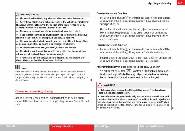
103Opening and closing
WARNING (Continued)
● Always take the vehicle key with you when you leave the vehicle.
● Never leave children or disabled persons in the vehicle, particularly ifthey have access to the keys. The misuse of the keys, for example, bychildren, may result in serious injury and accident.
● The engine may accidentally be started and be out of control.
● If the ignition is switched on, the electric equipment could be activa-ted with risk of injury, for example, in the electric windows.
● The doors can be locked using the remote control key. This could be-come an obstacle for assistance in an emergency situation.
● Always take the key with you when you leave the vehicle.
● The electric windows will work until the ignition has been switchedoff and one of the front doors has been opened.
● If necessary, use the safety switch to disable the rear electric win-dows. Make sure that they have been disabled.
NoteIf the window is not able to close because it is stiff or because of an ob-struction, the window will automatically open again ⇒ page 104. If thishappens, check why the window could not be closed before attempting toclose it again.
Convenience opening/closing
Use the convenience opening/closing function to easily open/close all the windows and the sliding/tilting sunroof* from the out-side.
Convenience open function
– Press and hold button on the remote control key until all thewindows and the sliding/tilting sunroof* have reached the de-sired position, or
– First unlock the vehicle using button on the remote controlkey and then keep the key in the driver door lock until all thewindows and the sliding/tilting sunroof* have reached the re-quired position.
Convenience close function
– Press and hold button on the remote control key until all thewindows and the sliding/tilting sunroof* are closed ⇒ , or
– Keep the key in the driver door in the "lock" position until all thewindows and the sliding/tilting sunroof* are closed.
Programming convenience opening in the Easy Connect*
– Select: function button CAR > control button Vehicle systems* >Vehicle settings > Central locking > Open the window by holdingbutton down or > Front window on/off or Sunroof on/off*
WARNING
● Take care when closing the sliding/tilting sunroof* and windows.There is a risk of suffering injury.
● For safety reasons, you should only use the remote control open andclose functions within about 2 metres of the vehicle. To avoid injuries, al-ways keep an eye on the windows and the sliding/tilting sunroof* whenpressing the button to close them. The windows stop moving as soon asthe button is released.
Safety First Operating instructions Practical Tips Technical specifications

104 Opening and closing
One-touch opening and closing*
One-touch opening and closing means you do not have tohold down the button.
Buttons ⇒ Fig. 60 1 , 2 , 3 and 4 have two positions for open-ing windows and two for closing them. This makes it easier to openand close windows to the desired position.
One-touch closing
– Pull up the window button briefly up to the second position. Thewindow closes fully.
One-touch opening
– Push down the window button briefly up to the second position.The window opens fully.
Restoring one-touch opening and closing
– The automatic open and close function will not work if the bat-tery has been temporarily disconnected. The function can be re-stored as follows:
– Close the window as far as it will go by lifting and holding theelectric window switch.
– Release the switch and then lift it again for one second. Thiswill re-enable the automatic function.
If you push (or pull) a button to the first stage, the window will open (orclose) until you release the button. If you push or lift the button briefly tothe second stage, the window will open (one-touch opening) or close (one-touch closing) automatically. If you operate the button while the window isopening or closing, it stops at this position.
Roll-back function
The roll-back function reduces the risk of injury when theelectric windows close.
● If a window is obstructed when closing automatically, the window stopsat this point and lowers immediately ⇒ .
● Next, check why the window does not close before attempting it again.
● If you try within the following 10 seconds and the window closes againwith difficulty or there is an obstruction, the automatic closing will stopworking for 10 seconds.
● If the window is still obstructed, the window will stop at this point.
● If there is no obvious reason why the window cannot be closed, try toclose it again by pulling the tab within ten seconds. The window closes withmaximum force. The roll-back function is now deactivated.
If more than 10 seconds pass, the window will open fully when you operateone of the buttons. One-touch closing is reactivated.
WARNING
● Incorrect use of the electric windows can result in injury.
● Always take the ignition key with you when leaving the vehicle, evenif you only intend to be gone for a short time. Please ensure that childrenare never left alone inside the vehicle.
● The electric windows will work until the ignition has been switchedoff and one of the front doors has been opened.
● Closing the windows without observing and ensuring it is clear couldcause serious injury to you and third parties. Make sure that no one is inthe path of a window.

105Opening and closing
WARNING (Continued)
● Never allow people to remain in the vehicle when you close the vehi-cle from the outside. The windows cannot be opened even in an emergen-cy.
● The roll-back function does not prevent fingers or other parts of thebody getting pinched against the window frame. Risk of accident.
Safety First Operating instructions Practical Tips Technical specifications

106 Opening and closing
Panoramic sliding sunroof*
Introduction
Additional information and warnings:
● SEAT information system ⇒ page 73
● Central locking and locking system ⇒ page 87
WARNING
Careless or uncontrolled use of the panoramic sliding sunroof can causeserious injuries.
● Only open or close the panoramic sliding sunroof when nobody is inthe way of its travel.
● Always take all the keys with you whenever you leave the vehicle.
● Never leave children or disabled persons in the vehicle, particularly ifthey have access to the keys. Uncontrolled use of the key could lock thevehicle, start the engine, turn on the ignition and operate the panoramicsliding sunroof.
● The panoramic sliding sunroof can be operated for up to about ten mi-nutes after the ignition has been switched off, provided the driver doorand the front passenger door are not opened.
NoteIn case of a fault in the operation of the panoramic sliding sunroof, the anti-trap function will not operate correctly. Visit a specialised workshop.
Opening or closing the panoramic sliding sunroof
Fig. 62 On the interiorroof lining: use the rotarybutton for opening andclosing
Fig. 63 On the interiorroof lining: Press the but-ton and pull on it to liftand close the slidingsunroof.
To completely close the panoramic sliding sunroof, the switch must be inthe position A .

107Opening and closing
effect Switch setting Necessary operations
⇒ Fig. 62
To open the slidingsunroof completely:
C
Rotate the switch to the re-quired position.
To choose the con-venience positionfor the sliding sun-
roof:
B
To close the slidingsunroof completely:
A
⇒ Fig. 63
To completely de-ploy the tilting sun-
roof:D
Briefly push the switchback (arrow).
To stop automaticoperation:
D or EBriefly push back the but-ton again or pull it.
To completely closethe tilting sunroof:
EBriefly push the switchback (arrow).
To set the inter-mediate position:
D or EPull the button or hold itback until the roof is in therequired position.
The panoramic sliding sunroof will only work with the ignition on. The pan-oramic sliding sunroof can be operated for up to about ten minutes after theignition has been switched off, provided the driver door and the front pas-senger door are not opened.
CAUTIONCheck that when the rear lid is open, it does not touch loads carried on theroof. When a roof carrier is fitted, DO NOT open the panoramic roof*.
Panoramic sliding sunroof: operation
Convenience open/close function
The panoramic sliding sunroof can be opened or closed from outside thevehicle using the vehicle key:
● Keep the vehicle unlocking or locking button pressed. The panoramicsliding sunroof is adjusted or closes.
● Release the unlock or lock button to stop the function.
During convenience closing, the windows and the panoramic sliding sun-roof close at the same time.
NoteThe rotary button of the panoramic sliding sunroof remains in the last posi-tion selected if the roof is closed using convenience closing from outsidethe vehicle, and will have to be re-positioned the next time you drive.
Roll-back function on panoramic sliding sunroof
The roll-back function can reduce the risk of injury when opening and clos-ing the panoramic sliding sunroof ⇒ . When the panoramic sliding sun-roof encounters an obstacle while closing, it rolls back and opens again.
● Check why the panoramic sliding sunroof does not close.
● Try to close the panoramic sliding sunroof again.
● If the panoramic sliding sunroof is still obstructed, it will stop at the cor-responding position. Next, close the panoramic sliding sunroof without theroll-back function.
Safety First Operating instructions Practical Tips Technical specifications

108 Opening and closing
Closing without the roll-back function
● The ⇒ Fig. 62 1 switch should be in the “closed” position A .
● Within five seconds of triggering the roll-back function, pull the controlall the way back ⇒ Fig. 63 (arrow E ) until the panoramic sliding sunroofcloses fully.
● The panoramic sliding sunroof closes without the roll-back function.
● If the panoramic sliding sunroof still cannot be closed, visit a special-ised workshop.
WARNING
Closing the panoramic sliding sunroof without the roll-back function mayresult in serious injury.
● Always close the panoramic sliding sunroof carefully.
● Make sure that nobody is in the way of the panoramic sliding sunroof,especially when it is closed without the roll-back function.
● The anti-trap function does not prevent fingers or other parts of thebody getting pinched against the window frame and causing injury.
NoteThe anti-trap function is activated if the windows and the panoramic slidingsunroof are closed from the outside of the vehicle using the ignition key forconvenience closing ⇒ page 103.

109Lights and visibility
Lights and visibility
Lights
Introduction
The legal requirements regarding the use of vehicle lights in each countrymust be observed.
The driver is personally responsible for the correct use and adjustment ofthe lights in all situations.
Additional information and warnings:
● Information system ⇒ page 73
● Changing bulbs ⇒ page 293
WARNING
If the headlights are regulated too high and the main beam is not usedcorrectly, there is a risk of dazzling or distracting other road users. Thiscould result in a serious accident.
● Always make sure that the headlights are correctly adjusted.
● Never use the main beam or headlight flasher when it can dazzle oth-er drivers.
Control lamps
lights up Possible cause Solution
Driving light totally or partiallyfaulty.
Replace the correspondingbulb ⇒ page 293.If all the bulbs are OK, the vehi-cle should be taken to a speci-alised workshop if necessary.
Rear fog light switched on.⇒ page 111.
Fog lights switched on
Left or right turn signal.The control lamp flashes twiceas fast when a vehicle or trailerturn signal is faulty.
If necessary, check the vehicleand trailer lighting.
Main beam on or flasher on. ⇒ page 110.
Light Assist on. ⇒ page 114
Several warning and control lamps should light up for a few seconds whenthe ignition is switched on, signalling that the function is being verified.They will switch off after a few seconds.
Safety First Operating instructions Practical Tips Technical specifications

110 Lights and visibility
WARNING
If the warning lamps and messages are ignored, the vehicle may stall intraffic, or may cause accidents and severe injuries.
● Never ignore the warning lamps or text messages.
● Stop the vehicle safely as soon as possible.
● Park the vehicle at a suitable distance away from the traffic ensuringthat the exhaust system is not in contact with inflammable material, forexample, dry grass, fuel, oil, etc.
● A faulty vehicle represents a risk of accident for the driver and for oth-er road users. If necessary, switch on the hazard warning lamps and putout the warning triangle to advise other drivers.
CAUTIONFailure to heed the control lamps and text messages when they appear mayresult in faults in the vehicle.
Turn signal and main beam lever*
Fig. 64 Turn signal andmain beam lever
Move the lever to the required position:
Right turn signal. Right-hand parking light (ignition switched off)⇒ page 112.
Left turn signal. Left-hand parking light (ignition switched off)⇒ page 112.
Main beam switched on ⇒ . The control lamp will light up on theinstrument panel.
Flashing the headlights. The flashed beam comes on if the lever ispressed. The control lamp will light up.
Push the lever all the way down to turn off the corresponding function.
Convenience turn signals
For the convenience turn signals, move the lever as far as possible upwardsor downwards and release the lever. The turn signal will flash three times.
The convenience turn signals are activated and deactivated in the Easy Con-nect system via the key and the Setup function button ⇒ page 79.
In vehicles that do not have the corresponding menu, this function can bedeactivated in a specialised workshop.
WARNING
Improper or lack of use of the turn signals, or forgetting to deactivatethem can confuse other road users. This could result in a serious acci-dent.
● Always give warning when you are going to change lane, overtake orwhen turning, activating the turn signal in good time.
● As soon as you have finished changing lane, overtaking or turning,switch the turn signal off.
WARNING
Incorrect use of the headlights may cause accidents and serious injury,as the main beam may distract or dazzle other drivers.
1
2
3
4

111Lights and visibility
Note● The turn signal only works when the ignition is switched on. The hazardwarning lights also work when the ignition is switched off.
● If a trailer turn signal malfunctions, the control lamp will stop flashing(trailer turn signals) and the vehicle turn signal will flash at double speed.
● The main beam headlights can only be switched on if the dipped beamheadlights are already on.
Turning lights on and off
Fig. 65 Dash panel:Light switch
The legal requirements regarding the use of vehicle lights in each countrymust be observed.
Turn the light switch to the required position ⇒ Fig. 65:
Symbol if the ignition is switched off when the ignition is on
Fog lights, dipped beam andside lights off.
Light off, or daytime driving lighton.
The “Coming home” and“Leaving home” guide lightsmay be switched on.
Automatic control of dippedbeam and daytime driving light.
Symbol if the ignition is switched off when the ignition is on
Side light on. Side light on.
Dipped beam off; if necessa-ry, the side light comes on fora time.
Dipped beam switched on.
Fog lights
The warning lamps or also show, on the light switch or instrumentpanel, when the fog lights are on.
● Switching on the fog lights : pull the light switch to the first position,from positions , or .
● Switching on the rear fog light : pull the light switch completely fromposition , or .
● To switch off the fog lights, press the light switch or turn it to position .
Audible warnings to advise the driver that the lights have not beenswitched off
If the key is not in the ignition and the driver door is open, an audible warn-ing signal is heard in the following cases: This is a reminder to turn off thelights.
● When the parking light is on ⇒ page 110.
● When the light switch is in position or .
WARNING
The side lights or daytime driving lights are not bright enough to illumi-nate the road ahead and to ensure that other road users are able to seeyou.
● Always use your dipped beam head lights if it is raining or if visibilityis poor.
Safety First Operating instructions Practical Tips Technical specifications

112 Lights and visibility
Lights and visibility: functions
Parking light
When the parking light is switched on, (right or left turn signal), the frontside light and the rear light on the corresponding side of the vehicle stay lit.The parking lights can only be activated with the ignition switched off andthe turn signal and main beam lever in the central position, before beingtriggered.
Parking light on both sides
With the ignition switched off and the light switch in position , when lock-ing the vehicle from the outside, the parking lights on both sides of the ve-hicle light up. In doing so, only the side lights of both headlights light up,and additionally the tail lights will do so partially.
Daytime driving light*
The daytime driving lights consist of individual lights, integrated in the frontheadlights. With the daylight driving lights on, only these lights switch on⇒ .
The daytime driving lights switch on every time the ignition is switched on,if the switch is in positions or , according to the level of exterior light-ing.
When the light switch is in position , a light sensor automaticallyswitches dipped beam on and off (including the control and instrumentlighting) or the daytime driving lights depending on the level of exteriorlighting.
Automatic dipped beam control
The automatic dipped beam control is merely intended as an aid and is notable to recognise all driving situations.
When the light switch is in position , the vehicle lights and the instru-ment panel and switch lighting switch on and off automatically in the fol-lowing situations ⇒ :
Automatic switching on: Automatic switching off:
The photo sensor detects darkness,for example, when driving through atunnel.
When adequate lighting is detected.
The rain sensor detects rain and ac-tivates the windscreen wipers.
When the windscreen wipers havebeen inactive for a few minutes.
Cornering lights*1)
When turning slowly or on very tight bends, the cornering lights are activa-ted automatically. The cornering lights may be integrated in the fog lightsand are switched on only at speeds of less than 40 km/h (25 mph).
When reverse gear is engaged, the cornering lights on both sides of the ve-hicle switch on, in order to better illuminate the area for parking.
Motorway lights*
The motorway light is available on vehicles equipped with full-LED lights.
The function is connected/disconnected via the corresponding Easy Con-nect system menu.
● Activation: When going above 110 km/h (75 mph) for more than 30 sec-onds, the dipped beam raises slightly to increase the distance of visibility ofthe driver.
● Deactivation: When reducing the speed of the car below 100 km/h, thedipped beam returns to its normal position.
1) This function is not available on vehicles equipped with full-LED headlights.

113Lights and visibility
WARNING
If the road is not well lit and other road users cannot see the vehicle wellenough or at all, accidents may occur.
● The automatic dipped beam control () only switches on the dip-ped beam when there are no changes in brightness, and not, for examplewhen it is foggy.
● Never drive with daytime lights if the road is not well lit due to weath-er or lighting conditions. Daytime lights do not provide enough light toilluminate the road properly or be seen by other road users.
● The rear lights do not come on with the daytime driving light. A vehi-cle which does not have the rear lights on may not be visible to otherdrivers in the darkness, in the case of heavy rain or in conditions of poorvisibility.
NoteIn cold or damp weather conditions, the headlights, tail lights and turn sig-nals may mist up inside temporarily. This is normal and in no way effectsthe useful life of the vehicle lighting system.
Hazard warning lights
The hazard warning lights are used to draw the attention ofother road users to your vehicle in emergencies.
Fig. 66 Dash panel:switch for hazard warn-ing lights
If your vehicle breaks down:
1. Park your vehicle at a safe distance from moving traffic.
2. Press the button to switch on the hazard warning lights ⇒ .
3. Switch the ignition off.
4. Apply the handbrake.
5. On a manual gearbox engage 1st gear. On an automatic gear-box, move the selector lever to P.
6. Use the warning triangle to draw the attention of other roadusers to your vehicle.
Safety First Operating instructions Practical Tips Technical specifications

114 Lights and visibility
7. Always take the vehicle key with you when you leave the vehi-cle.
Switch on the hazard warning lights to warn other road users, for example:
● reaching the tail end of a traffic jam,
● there is an emergency
● your vehicle breaks down due to a technical fault,
● you are towing another vehicle or your vehicle is being towed.
All turn signals flash simultaneously when the hazard warning lights areswitched on. The two turn signal turn signal lamps and the turn signallamp in the switch will flash at the same time. The hazard warning lightsalso work when the ignition is switched off.
Emergency braking warning
If the vehicle is braked suddenly and continuously at a speed of more than80 km/h (50 mph), the brake light flashes several times per second to warnvehicles driving behind. If you continue braking, the hazard warning lightswill come on automatically when the vehicle comes to a standstill. Theyswitch off automatically when the vehicle starts to move again.
WARNING
● The risk of an accident increases if your vehicle breaks down. Alwaysuse the hazard warning lights and a warning triangle to draw the atten-tion of other road users to your stationary vehicle.
● Never park where the catalytic converter could come into contact withinflammable materials under the vehicle, for example dry grass or spiltpetrol. This could start a fire!
Note● The battery will run down if the hazard warning lights are left on for along time, even if the ignition is switched off.
● The use of the hazard warning lights described here is subject to the rel-evant statutory requirements.
Main beam assist*
Main beam assist (Light Assist)
The main beam assist begins operating (within the limits of the system anddepending on the environmental and traffic conditions) starting at a speedof 60 km/h (37 mph), when it switches on automatically, and then deacti-vates again below 30 km/h (18 mph) ⇒ . This is managed via a camerasituated on the base of the interior mirror.
The main beam assist generally detects illuminated areas and deactivatesthe main beam when passing through a town, for example.

115Lights and visibility
Switching the main beam assist on and off
effect use
Activate:
– Switch the ignition on and turn the light switch to position.– From the base position, move the main beam and turn signallever forwards ⇒ page 110. When the warning lamp is dis-played on the instrument panel display, the main beam assist isswitched on.
Toswitchsystem
off:
– Switch off the ignition.– OR: Turn the light switch to a different position to ⇒ page 111.– OR: with main beam on, move the main beam and turn signallever backwards.– OR: Move the main beam and turn signal lever forwards tomanually switch main beam on. The main beam assist will thenbe deactivated.
Malfunctions
The following conditions may prevent the main beam headlight control fromturning off the headlights in time or from turning off altogether:
● In poorly lit towns with highly reflective signs.
● Other insufficiently lit road users (such as pedestrians or cyclists).
● On tight bends and steep slopes (bumps) and when oncoming vehiclesare partially obscured.
● When the drivers of other oncoming vehicles (such as a truck) can seeover a guard rail in the centre of the road.
● If the camera is damaged or the power supply is cut off.
● In fog, snow and heavy rain.
● With dust and sand turbulence.
● With loose gravel in the field of vision of the camera.
● When the field of vision of the camera is misted up, dirty or covered bystickers, snow, ice...
WARNING
The convenience features of the main beam assist should not encouragethe taking of risks. The system is not a replacement for driver concentra-tion.
● You are always in control of the main beam and adapting it to thelight, visibility and traffic conditions.
● It is possible that the main beam headlight control does not recog-nise all driving situations and is limited under certain circumstances.
● When the field of vision of the camera is dirty, covered or damaged,operation of the main beam control may be affected. This also applieswhen changes are made to the vehicle lighting system, for example, ifadditional headlights are installed.
CAUTIONTo avoid affecting the operation of the system, take the following points in-to consideration:
● Clean the field of vision of the camera regularly and make sure it is freeof snow and ice.
● Do not cover the field of vision of the camera.
● Check that the windscreen is not damaged in the area of the field of vi-sion of the camera.
NoteMain beam and headlight flasher can be turned on and off manually at anytime with the turn signal and main beam lever ⇒ page 110.
Adjusting the headlights
The light beam of the dipped beam lights is asymmetric: the side of theroad on which you are driving is lit more intensely.
Safety First Operating instructions Practical Tips Technical specifications

116 Lights and visibility
When a car that is manufactured in a country that drives on the right travelsto a country that drives on the left (or vice versa), it is normally necessary tocover part of the headlight bulbs with stickers or to change the adjustmentof the headlights to avoid dazzling other drivers.
In such cases, the regulations specify certain light values that must be com-plied with for designated points of the light distribution. This is known as“Tourist light”.
The light distribution that the halogen and full-LED headlights of the SEATLeon range have, allows the specific “tourist light” values to be met withoutthe need for stickers or changes in the settings.
Note“Tourist light” is only allowed temporarily. If you are planning a long stay ina country that drives on the other side, you should take the vehicle to anAuthorised Technical Service to change the headlights.
Coming home “function”
This function may be connected/disconnected through the radio menu. The“Coming Home” and/or “Leaving Home” delay functions may also be set(default: 30 sec.).
Vehicle with halo-gen headlights
In the “Coming Home” function, the daytime runninglights (DRL), the rear side lights and the licence platelights are turned on.
Vehicle with full-LED headlights
In the “Coming Home” function, the dipped beamsand the daytime running lights (DRL), the rear sidelights and the licence plate lights are switched on.
Automatic “Coming Home” activation*
For vehicles with a light and rain sensor (rotary light switch in position ).
● Switch off the engine and remove the key from the ignition with the rota-ry light switch in position ⇒ Fig. 65.
● The automatic “Coming Home” function is only active when the lightsensor detects darkness.
● When the car door is opened, the “Coming Home” lighting comes on.
Activation “Coming Home” manual
For vehicles with a light and rain sensor (rotary light switch without position).
● Switch off the engine and remove the key from the ignition.
● Activate the headlight flashers for approximately 1 second.
● Activated for any position of the rotary light switch.
● When the car door is opened, the “Coming Home” lighting comes on.The headlights are turned off 60 seconds after the vehicle door is opened.
Deactivation
● If no door has been closed, they go out automatically after 60 seconds.
● After the last door has been closed, the headlights will be switched offafter the “Coming Home” delay (as established in the radio menu).
● On turning the light switch to position ⇒ Fig. 65 .
● When the ignition is switched on (when starting the engine).
Leaving Home “function”
The “Leaving Home” function is only available for vehicles with a light andrain sensor (rotary light switch in position ).
This function may be connected/disconnected through the radio menu. The“Leaving Home” delay may also be set (default: 30 sec.).

117Lights and visibility
Vehicle with halo-gen headlights
In the “Leaving Home” function, the daytime runninglights (DRL), the rear side lights and the licence platelights are switched on.
Vehicle with full-LED headlights
In the “Leaving Home” function, the dipped beams,the daytime running lights (DRL), the rear side lightsand the licence plate lights are switched on.
Activation
● When the vehicle is unlocked using the remote control.
● The “Leaving Home” function is only activated when the rotary lightswitch is in position and the light sensor detects darkness.
Deactivation
● When the “Leaving Home” lights go out after the delay period (default:30 sec.).
● When the vehicle is locked using the remote control.
● When the light control is switched into a position other than .
● With the ignition is switched on.
Headlight range control, lighting of the instrument paneland controls
Fig. 67 Next to thesteering wheel: Head-light range control
Lighting of the instrument panel and controls*
Depending on the model, lighting of the instrument panel and controls canbe adjusted in the Easy Connect system, using the button and the func-tion button SETUP ⇒ page 82.
Headlight range control
The headlight range control ⇒ Fig. 67 is modified according to the value ofthe headlight beam and the vehicle load status. This offers the driver opti-mum visibility and the headlights do not dazzle oncoming drivers ⇒ .
The headlights can only be adjusted when the dipped beam is switched on.
To reset, turn switch ⇒ Fig. 67:
Value Vehicle load statusa)
– Two front occupants, luggage compartment empty
1 All seats occupied, luggage compartment empty
2All seats occupied, luggage compartment full With trailerand minimum drawbar load
3Driver only, luggage compartment full With trailer andmaximum drawbar load
a) If the vehicle load does not correspond to those shown in the table, it is possible to selectintermediary positions.
Dynamic headlight range control
The control is not mounted in vehicles with dynamic headlight range con-trol. The headlight range is automatically adjusted according to the vehicleload status when the headlights are switched on.
Instrument panel lighting
In vehicles with the daytime driving light, the instrument panel lightingswitches on in dark conditions (for example, when passing through a tun-nel). This reminds the driver to manually switch on the dipped beam, sothat the vehicle rear lights also switch on ⇒ page 112.
Safety First Operating instructions Practical Tips Technical specifications

118 Lights and visibility
WARNING
Heavy objects in the vehicle may mean that the headlights dazzle anddistract other drivers. This could result in a serious accident.
● Adjust the light beam to the vehicle load status so that it does notblind other drivers.
Interior and reading lights1)
Button/Position
effect
Switches interior lights off.
Switches interior lights on.
Switches door contact control on (central position).The interior lights come on automatically when the vehicle isunlocked, a door is opened or the key is removed from the ig-nition.The lights go off a few seconds after all the doors are closed,the vehicle is locked or the ignition is switched on.
Turning the reading light on and off
Glove compartment and luggage compartment lighting*
When opening and closing the glove compartment on the front passengerside and the rear lid, the respective light will automatically switch on andoff.
Footwell lighting*
The lights in the footwell area below the dash (driver and front passengersides) will switch on when the doors are opened and will decrease in inten-sity while driving. The intensity of these lights can be adjusted using the ra-dio menu (see Easy Connect > Adjusting Lighting > Interior lighting⇒ page 82).
Ambient light*
The ambient light in the door panel changes colour (white or red) depend-ing on the driving mode. The intensity of these lights can be adjusted usingthe radio menu (see Easy Connect > Adjusting Lights > Interior lighting⇒ page 82).
NoteThe reading lights switch off when the vehicle is locked using a key or afterseveral minutes if the key is removed from the ignition. This prevents thebattery from discharging.
Sun protection equipment
Introduction
WARNING
Folded sun blinds can reduce visibility.
● Always store sun blinds and visors in their housing when not in use.
1) Depending on the level of equipment fitted in the vehicle, LEDs can be used for the follow-ing interior lights: front courtesy light, rear courtesy light, footwell light and sun visor light.

119Lights and visibility
Sun visors
Fig. 68 Sun visor
Options for adjusting driver and front passenger sun visors:
● Lower by unfolding towards the windscreen.
● The sun visor can be pulled out of its mounting and turned towards thedoor ⇒ Fig. 68 1 .
● Swing the sun visor towards the door, longitudinally backwards.
Vanity mirror light
There may be a vanity mirror, with a cover, on the rear of the sun visor. Whenthe cover is opened 2 a light comes on.
The lamp goes out when the vanity mirror cover is closed or the sun visor ispushed back up.
NoteThe light above the sun visor automatically switches off after a few minutesin certain conditions. This prevents the battery from discharging.
Applies to the model: LEON ST
Sun blind*
The windows on the rear doors may be fitted with a sunblind
Fig. 69 Rear window:sun blind
Rear door sun blind*
– Pull out the blind and attach it to the hook at the top of the doorframe, in the centre ⇒ Fig. 69.
Safety First Operating instructions Practical Tips Technical specifications

120 Lights and visibility
Windscreen wiper and rear wiper systems
Introduction
Additional information and warnings:
● Changing wheels round
● Heating, ventilation, cooling
● Caring for and cleaning the vehicle exterior
WARNING
If the water from the windscreen washer does not contain enough anti-freeze, it may freeze on the windscreen and rear window, reducing for-ward and rear visibility.
● In winter, ensure the windscreen washer contains enough anti-freeze.
● In cold conditions, you should not use the wash/wipe system unlessyou have warmed the windscreen with the ventilation system. The anti-freeze could freeze on the windscreen and reduce visibility.
WARNING
Worn or dirty wiper blades reduce visibility and increase the risk of acci-dent and serious injury.
● Always replace damaged or worn blades or blades which do not cleanthe windscreen correctly.
CAUTIONIn icy conditions, always check that the wiper blades are not frozen to theglass before using the wipers. In cold weather, it may help to leave the vehi-cle parked with the wipers in service position ⇒ page 122.
Control lamp
lights up Possible cause Solution
Windscreen wiper fluid leveltoo low
Top up the windscreen wiperreservoir as soon as possible⇒ page 124.
Several warning and control lamps should light up for a few seconds whenthe ignition is switched on, signalling that the function is being verified.They will switch off after a few seconds.
CAUTIONFailure to heed the control lamps and text messages when they appear mayresult in faults in the vehicle.

121Lights and visibility
Window wiper lever
Fig. 70 Operating thewindscreen wiper andrear wiper
Move the lever to the required position ⇒ :
0 Windscreen wiper off.
1 Windscreen wipers interval wipe.Using the control ⇒ Fig. 70 A adjust the interval (vehicleswithout the rain sensor), or the sensitivity of the rain sensor.
2 Slow wipe.
3 Continuous wipe.
4 Brief press, short clean. Hold the lever down for more time toincrease the wipe frequency.
5 The windscreen washer function is activated by pushing thelever forwards, and simultaneously the windscreen wipersstart.
Move the lever to the required position ⇒ :
6 Interval wipe for rear window. The rear wiper will wipe thewindow approximately every six seconds.
7 The windscreen washer function is activated by pressing thelever, and the rear wiper starts simultaneously.
CAUTIONIf the ignition is switched off with the windscreen wipers active, they com-plete their wipe before returning to the rest position. Ice, snow and otherobstacles on the windscreen may damage the wiper and the windscreenwiper motor.
● If necessary, remove snow and ice from the windscreen wipers beforestarting your journey.
● Carefully lift the frozen windscreen wipers from the glass. SEAT recom-mends a de-icer spray for this operation.
CAUTIONDo not switch on the windscreen wipers if the windscreen is dry. Cleaningwith the windscreen wipers while dry can cause damage.
Note● The windscreen wiper and rear wiper system only function when the ig-nition is switched on and the bonnet or rear lid, respectively, are closed.
● The interval wipe speed varies according to the vehicle speed. The fasterthe vehicle is moving, the more often the windscreen is cleaned.
● The rear wiper is automatically switched on when the windscreen wiperis on and the car is in reverse gear.
Safety First Operating instructions Practical Tips Technical specifications

122 Lights and visibility
Windscreen wiper functions
Windscreen wiper performance in different situations:
If the vehicle is at a stand-still:
The activated position provisionally changesto the previous position.
During the automatic wipe:
The air conditioner comes on for approxi-mately 30 seconds in air recirculation modeto prevent the smell of the windscreen wash-er fluid entering the inside the vehicle.
For the interval wipe:The intervals between wipes vary accordingto the speed of the vehicle. The higher thevehicle speed the shorter the intervals.
Heated windscreen washer jets
The heating only thaws the frozen jets, it does not thaw the water in thewasher hoses. The heated windscreen washer jets automatically adjust theheat depending on the ambient temperature, when the ignition is switchedon.
Headlight wash/wipe system
The headlight washers/wipers clean the headlight lenses.
After the ignition is switched on, the first and every fifth time the wind-screen washer is switched on, the headlights are also washed. Therefore,the windscreen wiper lever should be pulled towards the steering wheelwhen the dipped beam or main beam are on. Any incrusted dirt (such as in-sects) should be cleaned regularly (e.g. when refuelling).
To ensure the headlight washers work correctly in winter, any snow whichhas got into the bumper jet supports should be cleaned away. If necessary,remove snow with an anti-icing spray.
NoteThe wiper will try to wipe away any obstacles that are on the windscreen.The wiper will stop moving if the obstacle blocks its path. Remove the ob-stacle and switch the wiper back on again.
Windscreen wipers service position
Fig. 71 Wipers in serviceposition
The wiper arms can be raised when the wipers are in service position⇒ Fig. 71. To place the windscreen wipers in the service position, proceedas follows:
● The bonnet must be closed ⇒ page 251.
● Switch the ignition on and off.
● Press the windscreen wiper lever downwards briefly ⇒ Fig. 70 4 .
Before driving, always lower the wiper arms. Using the windscreen wiperlever, the windscreen wiper arms return to their initial position.

123Lights and visibility
Lifting and returning windscreen wiper arms
● Place the wiper arms in the service position ⇒ .
● Only hold the wiper arms at the point where the blade is fixed.
CAUTION● To prevent damage to the bonnet and the wiper arms, only leave them inthe service position.
● Before driving, always lower the wiper arms.
Rain sensor*
Fig. 72 Windscreen wip-er lever: adjusting therain sensor A
Fig. 73 Rain sensor sen-sitive surface
The rain sensor controls the frequency of the windscreen wiper intervals,depending on the amount of rain ⇒ . The sensitivity of the rain sensor canbe adjusted manually. Manual wipe ⇒ page 121
Move the lever to the required position ⇒ Fig. 72:
Rain sensor off.
Rain sensor on; automatic wipe if necessary.
Setting sensitivity level of rain sensor
– Set control to the right: highly sensitive.
– Set control to the left: less sensitive.
When the ignition is switched off and then back on, the rain sensor stays onand starts operating again when the windscreen wipers are in position 1
and the vehicle is travelling at more than 16 km/h (10 mph).
Rain sensor modified behaviour
Possible causes of faults and mistaken readings on the sensitive surface⇒ Fig. 73 of the rain sensor include:
0
1
A
Safety First Operating instructions Practical Tips Technical specifications

124 Lights and visibility
● Damaged blades: A film of water on the damaged blades may lengthenthe activation time, reduce the washing intervals or result in a fast and con-tinuous wipe.
● Insects: insects on the sensor may trigger the windscreen washer.
● Salt on roads: in winter, salt spread in the roads may cause an extralong wipe when the windscreen is almost dry.
● Dirt: dry dust, wax, coating on glass (Lotus effect) or traces of detergent(car wash) may reduce the effectiveness of the rain sensor or make it reactmore slowly, later or not at all.
● Cracked windscreen: the impact of a stone will trigger a single wipe cy-cle with the rain sensor on. Next the rain sensor detects the reduction in thesensitive surface area and adapts accordingly. The behaviour of the sensorwill vary with the size of the damage caused by the stone.
WARNING
The rain sensor may not detect enough rain to switch on the wipers.
● If necessary, switch on the wipers manually when water on the wind-screen obstructs visibility.
Note● Clean the sensitive surface of the rain sensor regularly and check theblades for damage ⇒ Fig. 73 (arrow).
● To remove wax and coatings, we recommend a window cleaner contain-ing alcohol.
Checking and topping up the windscreen washer reservoirwith water
Fig. 74 In the enginecompartment: wind-screen washer reservoirtop
Check the water level in the windscreen washer reservoir regularly and topup as required.
● Open the bonnet ⇒ page 251.
● The washer reservoir is marked with the symbol on the lid ⇒ Fig. 74.
● Check there is enough water in the reservoir.
● To top up, mix water with a window cleaner recommended by SEAT ⇒ .Please follow the instructions for use found on the packaging.
● In cold weather, a special antifreeze should also be added to preventthe water from freezing ⇒ .

125Lights and visibility
Recommended windscreen wipers
● For the hottest seasons we recommend summer G 052 184 A1 for clearglass. Proportions of the mixture in the washer fluid tank: 1:100 (1 part con-centrate per 100 parts water).
● All year round, G 052 164 A2 for clear glass. Approximate proportion ofthe winter mixture, up to -18 °C (0 °F): 1:2 (1 part concentrate per 2 partswater); otherwise, a 1:4 proportion of mixture in the washer fluid tank.
Reservoir capacity
The reservoir holds approximately 3 - 4 litres; in vehicles with headlightwasher, it is approximately 3 -6 litres.
WARNING
Never mix an unsuitable antifreeze or other similar additives with thewindscreen washer water. A greasy layer may be formed on the wind-screen which will impair visibility.
● Use clean water with a window cleaner recommended by SEAT.
● If necessary, add a suitable antifreeze to the water in the reservoir.
CAUTION● Do not mix cleaning products recommended by SEAT with other prod-ucts. This could lead to flocculation and may block the windscreen washerjets.
● When topping up service fluids, make absolutely certain that you fill thefluids into the correct reservoirs. Using the wrong fluids could cause seriousmalfunctions and engine damage!
Rear vision mirror
Adjusting the exterior mirrors
Fig. 75 Driver door: con-trol for the exterior mirror
Turn the knob to the appropriate position:
– In these positions you can adjust the exterior mirrors (left or right) bymoving the control in the desired direction.
– The surfaces of the exterior mirrors are heated* depending on theoutside temperature, and on the equipment fitted in the vehicle.
– The exterior mirrors are retracted*.
Synchronized regulation of the exterior mirrors
● In the Settings - Convenience menu, select whether or not the exteriormirrors should move in synchronisation.
● Turn the knob to position L.
● Adjust the left-hand exterior mirror. The right exterior mirror will be ad-justed at the same time (synchronised).
L/R
Safety First Operating instructions Practical Tips Technical specifications

126 Lights and visibility
● If necessary the right exterior mirror adjustment may need correcting.Turn the knob to position R.
● In the Easy Connect system the exterior mirrors can be adjusted usingthe CAR button and the function button SETUP .
Tilt function for front passenger exterior mirror*
The mirror can automatically tilt slightly to provide a better view of the kerbwhen parking backwards. The control must be in the position R for this fea-ture to be operational.
The mirror returns to its original position as soon as you drive forwards atover 15 km/h (10 mph) or switch off the ignition. It also returns to its origi-nal position if the position of the control is adjusted.
Storing the settings of the passenger's exterior mirror for the tilt function
● Switch the ignition on.
● On the control, select position R.
● Select reverse gear.
● Adjust the front passenger exterior mirror so that you can see, for exam-ple, the kerb area.
● Disengage the reverse gear.
● The rear view mirror setting is stored.
WARNING
Convex or wide-angle* exterior mirrors give a larger field of vision. How-ever, they make objects look smaller and further away than they reallyare. If you use these mirrors to estimate the distance to vehicles behindyou when changing lane, you could misjudge the distance. Risk of acci-dent!
CAUTION● If one of the mirror housings is knocked out of position (e.g. when park-ing), the mirrors must first be fully retracted with the electric control. Do notreadjust the mirror housing by hand, as this will interfere with the mirror ad-juster function.
● Before washing the vehicle in an automatic car wash, please make sureto retract the exterior mirrors to prevent them from being damaged. Electri-cally retractable exterior mirrors must not be folded in or out by hand. Al-ways use the electrical power control.
NoteIf the electrical adjustment should fail to operate, both of the mirrors can beadjusted by hand by lightly pressing the edge of the mirror glass.
Anti-dazzle rear vision mirrors
Your vehicle is fitted with an interior rear vision mirror with amanual or automatic control for anti-dazzle position.
Fig. 76 Interior rear vi-sion mirror with automat-ic setting for anti-dazzleposition

127Lights and visibility
Interior rear vision mirror with manual setting for anti-dazzleposition
– Position the small lever of the lower edge of the mirror to facetowards the rear.
Anti-dazzle rear vision mirror with automatic setting*
– Press the button A . Warning lamp B will light up. The interiormirror will darken automatically when bright light (e.g. from theheadlights of a following vehicle) shines on its.
WARNING
In the event that an automatic anti-dazzle rear vision mirror breaks, anelectrolyte fluid may leak. This could cause irritation to the skin, eyesand respiratory organs. If you come into contact with this liquid, it mustbe rinsed with large quantities of water. If necessary, get medial help.
CAUTIONIn the event that an automatic anti-dazzle rear vision mirror breaks, an elec-trolyte fluid may leak. This liquid attacks plastic surfaces. Clean the liquidwith a wet sponge as soon as possible.
Note● If the light incident in the interior rear vision mirror is obstructed (e.g.with the sun blind*), the anti-dazzle rear vision mirror with automatic set-ting will not operate perfectly.
● When the interior lights are on or reverse gear engaged, the rear visionmirrors do not darken with automatic adjustment for anti-dazzle position.
Safety First Operating instructions Practical Tips Technical specifications

128 Seats and storage
Seats and storage
General notes
WARNING
The Safe driving chapter contains important information, tips, sugges-tions and warnings that you should read and observe for your own safetyand the safety of your passengers ⇒ page 7.

129Seats and storage
Front seats
Manual seat adjustment
Fig. 77 Front seats:manual seat adjustment
Fig. 78 Front seats: leverfor folding the backrest(3-door vehicles)
Adjusting the seat forward/backward: pull the lever and move the seatforwards or backwards.
Raise/lower the seat: Pull/push the lever.
Backrest lower/raise: turn the hand wheel.
1
2
3
Adjusting the lumbar support* : press the button in the correspondingposition.
Folding the seat backrest (only 3-door vehicles): pull the lever and pushthe backrest forward.
WARNING
● Adjust the front seats only when the vehicle is stationary. Failure todo so could result in an accident.
● Be careful when adjusting the seat height. Careless or uncontrolledadjustment can cause injuries.
● The front seat backrests must not be reclined for driving. Otherwise,seat belts and the airbag system might not protect as they should, withthe subsequent danger of injury.
Applies to the model: LEON ST
To lower the front passenger seat back*
Fig. 79 Passenger'sseat: lever for foldingdown the backrest
The passenger's seat can be down to expand the luggage compartmentloading area.
4
5
Safety First Operating instructions Practical Tips Technical specifications

130 Seats and storage
● Pull on lever 1 ⇒ Fig. 79 and push the backrest forwards so that thebackrest is horizontal.
WARNING
When the passenger's backrest is folded down this place cannot be occu-pied by a passenger.
Front centre armrest
The centre armrest can be adjusted to various levels.
Adjusting the centre armrest
– To adjust the tilt, lift the armrest from the starting position sothat it is engaged.
– To return the armrest to the starting position, remove the arm-rest from the upper fixed position and lower it.
The armrest can be moved backwards and forwards.
Seat functions
Introduction
Additional information and warnings
● Adjusting the position of the seats ⇒ page 10
● Seat belts ⇒ page 20
● Airbag system ⇒ page 31
● Child seats (accessories) ⇒ page 48
WARNING
Inappropriate use of the seat functions can cause severe injuries.
● Assume the proper sitting position before your trip and remain in itthroughout. This also applies to the other occupants.
● Always keep hands, fingers, feet and other parts of the body awayfrom the operating radius and the adjustment of seats.
Seat heating
Fig. 80 In the centreconsole: front seats heat-ing switch
The seat cushions can be heated electrically when the ignition is switchedon. The backrest is also heated in some versions.
The seat heating should not be engaged in any of the following conditions:
● The seat is unoccupied.
● The seat has a covering.
● There is a child seat installed in the seat.

131Seats and storage
● The seat cushion is wet or damp.
● The indoor or outdoor temperature is greater than 25 °C (77 °F).
effect Using seat heating
To switch sys-tem on:
Press the button or . Seat heating is switched on fully.
Adjusting theheating out-put:
Press the button or repeatedly until the desired inten-sity level is reached.
To switch sys-tem off:
Press the button or until all warning lamps switch off.
WARNING
People who, because of medications, paralysis or chronic diseases (e.g.diabetes) cannot perceive pain or temperature, or have a limited percep-tion thereof, may suffer burns to the back, buttocks or legs when usingseat heating, an occurrence that may entail a very lengthy recovery peri-od or from which it may not be possible to recover fully. Seek medical ad-vice if you have doubts regarding your health.
● People with a limit pain and temperature threshold must never useseat heating.
WARNING
If the fabric of the cushion is wet, this can adversely affect the operationof the seat heating, increasing the risk of burns.
● Make sure the seat cushion is dry prior to using the seat heater.
● Do not sit on the seat with clothing that is wet or damp.
● Do not leave clothing that is wet or damp on the seat.
● Do not spill liquid on the seat.
CAUTION● To avoid damaging the heating elements of the seat heating, please donot kneel on the seat or apply sharp pressure at a single point to the seatcushion and backrest.
● Liquids, sharps objects and insulating materials (e.g., covers or childseats) can damage the seat heating.
● In the event of odours, switch off the seat heating immediately and havethe unit inspected by a specialised workshop.
For the sake of the environmentThe seat heating should remain on only when needed. Otherwise, it is anunnecessary fuel waste.
Head restraints
Adjusting the head restraints
Fig. 81 Front seat: ad-justment of the head re-straint
Safety First Operating instructions Practical Tips Technical specifications

132 Seats and storage
Adjust the head restraint so that the top of the head restraint is lev-el with the top of your head. When this is not possible, try to get asclose as possible to this position.
– Grasp the sides of the head restraint with both hands and moveit up/down (to lower you must press button 1 ) until you see itengage.
Rear head restraints
Fig. 82 Rear centre headrestraint: release point
When transporting people in the back seat, place the head re-straints of the occupied seats at a minimum of the next socket up⇒ .
Adjusting the head restraints
– To set the head restraint higher, grasp the sides with bothhands and move it upwards, until you see it engage.
– To set the head restraint lower down, press the A ⇒ Fig. 82button and move it downwards.
Removing the head restraint
To remove the head restraint, the corresponding backrest must bepartially folded forward.
– Unlock the backrest ⇒ page 138.
– Move the head restraint upwards until it arrives to the top.
– Press the A ⇒ Fig. 82 button while at the same time removingthe head restraint from the backrest ⇒ .
– Insert a screwdriver in the B position of the hole while at thesame time removing the head restraint from the backrest ⇒ .
– Move the backrest until it engages properly ⇒ .
Fitting the head restraint
To mount the external head restraints, the corresponding backrestmust be partially folded forward.
– Unlock the backrest ⇒ page 138.
– Insert the head restraint bars into the guides until they percept-ibly engage. It should not be possible to remove the head re-straint from the backrest.
– Move the backrest until it engages properly ⇒ .
WARNING
● Please observe the general notes.
● Remove the rear head restraints only when it is necessary for theplacement of a child seat ⇒ page 48. After removing a child seat, remountthe head restraint immediately. Travelling with the head restraints re-moved or improperly adjusted increases the risk of severe injuries.

133Seats and storage
Storage compartments
Storage areas under the front seats*
There is a storage compartment with a cover under eachfront seat.
Fig. 83 Storage com-partment under the frontseats
The drawer* is opened by pulling on the cover ⇒ Fig. 83.
To close the drawer, press the cover until it locks into position.
WARNING
● The drawers will hold a maximum weight of 1.5 kg.
● Do not drive with the drawer cover open. There is an injury risk forpassengers if the cargo is released in case of sudden braking or an acci-dent.
Applies to the model: LEON ST
Folding table*
Fig. 84 Left-hand frontseat: folding table
– To open the tray, open it up in the direction of the arrow⇒ Fig. 84.
WARNING
● The folding trays may not be folded down whilst the vehicle is in mo-tion and anyone is seated on the second row of seats. There is a risk ofinjury during a sudden braking manoeuvre! The tray must therefore beclosed and properly secured whilst the vehicle is in motion.
● Do not put hot drinks in the drink holders. During normal or suddendriving manoeuvres, sudden braking or an accident, the hot drink couldbe spilled. Danger of scalding.
CAUTIONWhen driving, do not leave open cans in the cup holders. The drink mightbe spilt on braking, for example, and could damage the vehicle.
Safety First Operating instructions Practical Tips Technical specifications

134 Seats and storage
Drink holders
Fig. 85 Centre console:Front drink holders
Front drink holders
– Place drinks in the holder ⇒ Fig. 85. Placement of two drinks ispossible. There is also the possibility of placing larger plasticbottles in the trims of the doors.
WARNING
● Do not place any hot drinks in the drink holder while the vehicle ismoving. Hot drinks could spill and cause burns, which may cause an acci-dent.
● Do not use hard china cups or glasses. These could cause injury in theevent of an accident.
CAUTIONYou should avoid putting open drinks containers in the cup holders. Thedrinks could otherwise spill over and cause damage to e.g. the electricalequipment or the seat covers.
Glove box
Fig. 86 Glove compart-ment
Opening/closing
– To open the glove compartment, pull the handle in the directionof the arrow.
– To close the glove compartment, move the cover upwards untilit engages.
Depending on the vehicle equipment, the CD player is located in the glovecompartment. Separate operating instructions are enclosed for this equip-ment in the corresponding Instruction Manual.
WARNING
The cover of the glove compartment should always be closed while driv-ing. Failure to do so could result in an accident.
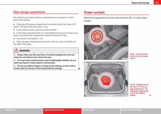
135Seats and storage
Other storage compartments
You will find more object holders, compartments and supports in otherparts of the vehicle:
● In the top of the glove compartment in vehicles that do not have a CDreader. The load must not exceed 1.2 kg.
● In the centre console under the centre armrest*.
● In the driver side panel there is a removable box for access to fuses andrelays. The load of the compartment should not exceed 0.2 kg.
● Coat hooks in the pillar B ⇒ .
● Other storage compartments are found in the rear seat, to the left andthe right of the seats.
WARNING
● Please make sure that any items of clothing hanging from the coathooks do not obstruct your view to the rear.
● The coat hooks should only be used for lightweight clothing. Do notleave any heavy or sharp objects in the pockets.
● Do not use clothes hangers to hang up the clothing, as this could in-terfere with the function of the head-protection airbags.
Power sockets
Electrical equipment can be connected to the 12 volt powersocket.
Fig. 87 Centre console:front/rear 12-volt powersocket
Fig. 88 Detailed view ofthe side trim in the lug-gage compartment: 12-volt power sockets (validonly for the LEON STmodel)
Safety First Operating instructions Practical Tips Technical specifications

136 Seats and storage
In the centre console
– Remove the connector located in the centre console of the pow-er socket ⇒ Fig. 87.
– Insert the plug of the electrical appliance into the power socket.
In the luggage compartment (valid only for the Leon ST model)
– Lift the power socket cover ⇒ Fig. 88.
– Insert the plug of the electrical appliance into the power socket.
Electrical equipment can be connected to the 12 volt power socket. The ap-pliances connected to each power socket must not exceed a power rating of120 Watt.
WARNING
The power socket works only when the ignition is on. Improper use maycause serious injury or even fire. Children should therefore not be left inthe vehicle, unattended, if the button is also left behind. Otherwise thereis a possibility that they may be injured.
CAUTIONAlways use the correct type of plugs to avoid damaging the sockets.
NoteThe use of electrical appliances with the engine switched off will cause abattery discharge.
Luggage compartment
General notes
WARNING
The Safe driving chapter contains important information, tips, sugges-tions and warnings that you should read and observe for your own safetyand the safety of your passengers ⇒ page 7.

137Seats and storage
Applies to the model: LEON / LEON SC
Increase capacity of luggage compartment
The backrests can be folded forward individually or togeth-er.
Fig. 89 Clip to supportthe seat belt
Fig. 90 Backrest releaselever
Folding the backrest forwards
– Place the side seat belts in the trim clip ⇒ Fig. 89.
– Slide the head restraint(s) downwards ⇒ page 132.
– Press the release lever ⇒ Fig. 90 A in the direction of the ar-row.
– Fold the backrest forwards.
Returning the backrest to its upright position
– Move the backrest until it engages properly ⇒ . The red mark-ing on the tab ⇒ Fig. 90 B should no longer be visible whenthe backrest is properly secured.
WARNING
● Make sure that the rear backrest is securely locked in position so thatthe seat belt can provide proper protection on the centre rear seat.
● The rear backrest must always be securely latched so that objectsstored in the luggage compartment will not fly forward through the inte-rior during sudden braking.
CAUTION● With the backrest inclined there is a danger of damaging the rear headrestraints when adjusting the front seats backwards.
● When folding the backrest forwards, make sure to place the side seatbelts in the trim clip to prevent them from being damaged by becomingtrapped in the backrest lock.
Safety First Operating instructions Practical Tips Technical specifications

138 Seats and storage
Applies to the model: LEON ST
Folding down and lifting the rear seat backrest
Fig. 91 In the rear seatbackrest: release tab 1 ;red marking 2
Fig. 92 In the luggagecompartment: distanceunlocking levers of leftpart 1 and right part 2 ofthe rear backrest
The rear seat backrest is divided and each part can be folded down sepa-rately to extend the boot.
When the rear seat backrest is folded down, nobody is allowed to travel inthe corresponding seats (not even a child).
Folding down the rear seat backrest with the release tab
● Push the head restraint down as far as it will go.
● Push the release tab ⇒ Fig. 91 1 forwards and at the same time folddown the backrest.
● The rear backrest is released when the red mark of button 2 can beseen.
Fold down the rear seat backrest with the distance unlocking lever
● Push the head restraint down as far as it will go.
● Open the rear lid.
● Pull on the distance unlocking lever of the left part ⇒ Fig. 92 1 or right2 of the backrest in the direction of the arrow. The unlocked part of the
rear backrest is folded down automatically forwards.
● As applicable, close the rear lid.
The rear backrest is released when the red mark on button ⇒ Fig. 91 2 canbe seen.
Folding up the rear seat backrest
● Lift the backrest and press it firmly in the lock until it engages properly⇒ .
● It should not be possible to see the red mark of the release tab 2 .
● The backrest has to be properly engaged.
WARNING
If the rear seat backrest is folded down or lifted carelessly it may causeserious injury.
● Never fold down or lift the rear seat backrest while driving.

139Seats and storage
WARNING (Continued)
● On lifting the rear seat backrest, avoid trapping or damaging the seatbelt.
● On folding down or lifting the rear seat backrest, always keep yourhands, fingers, feet and other body parts out of its path.
● For the safety belts to offer the necessary protection, all the parts ofthe rear backrest should always be properly engaged. This is particularlyimportant in the case of the rear centre seat. Anyone sitting in a seatwhose backrest is not properly engaged could fly forward, together withthe backrest in the event of a sudden braking, a brusque manoeuvre oran accident.
● A red mark on the button 2 warns that the backrest is not engaged.Always check that the red marking is not visible when the backrest is inthe upright position.
● When the rear seat backrest is folded down or not properly engaged,nobody is allowed to travel in the corresponding seats (not even a child).
CAUTIONIf the rear seat backrest is folded down or lifted carelessly it may causedamage to the vehicle or other objects.
● Before folding the rear seat backrest, adjust the front seats so that nei-ther the head restraints nor the padding of the rear backrest hit them.
Applies to the model: LEON / LEON SC
Luggage compartment cover
The luggage compartment cover blocks the view into theluggage compartment.
Fig. 93 Rear lid openwith the luggage com-partment cover
Removing
– Remove the straps A and unfasten the cover of the support B
by pressing upwards in the direction of arrow 1 .
Fitting
– Insert the cover horizontally so that it coincides with the “plate”on the axis of the supports B and press down until it engages.
– Attach the straps to the rear lid A ⇒ .
Safety First Operating instructions Practical Tips Technical specifications

140 Seats and storage
WARNING
● The luggage compartment cover must always be fixed properly (riskof accident).
● The luggage compartment cover should not be used as a storageshelf. Articles placed on this cover could cause injury to vehicle occu-pants in an accident or if the brakes are applied suddenly.
Applies to the model: LEON ST
Retractable rear shelf
Fig. 94 In the luggagecompartment: closing therear shelf
Fig. 95 In the luggagecompartment: removingthe rear shelf
opening the rear shelf
● Press the handle of the rear shelf (press) until it is released ⇒ Fig. 941 . The shelf will slide automatically to the end until it is totally retracted.
Closing the rear shelf
● Pull backwards and evenly on the rear shelf.
Removing the rear shelf
● Press the rear shelf support ⇒ Fig. 95 1 in the direction of the arrow.
● Pull the rear shelf upwards through the support.
● In versions with side covers (without nets) the rear shelf can be storedunder the luggage compartment variable floor, although it must be in thetop position ⇒ page 141.
Mounting the rear shelf
● Place the rear shelf in the housing provided for in the left side trim.
● Fit the rear shelf support ⇒ Fig. 95 1 into the right housing.
● Check that the support ⇒ Fig. 95 1 has engaged properly.

141Seats and storage
WARNING
If animals or other vehicles or stationary objects are carried incorrectlyon the rear shelf, they could cause serious injuries in case of suddenbraking or brusque manoeuvre or an accident.
● Do not leave hard, heavy or sharp objects loose on the rear shelf.
● Never transport animals on the rear shelf.
Applies to the model: LEON ST
Storing the rear shelf
Fig. 96 In the luggagecompartment: housingfor storing the rear shelf.
Fig. 97 In the luggagecompartment: housingfor storing the rear shelf.
The rear shelf can be stored under the luggage compartment's variablefloor.
● Remove the covers ⇒ Fig. 96 A left and right.
● Press the head of the rear shelf in the direction of the arrow until it en-gages in the housing provided ⇒ Fig. 97.
● Put the left and right covers back in their original position.
Safety First Operating instructions Practical Tips Technical specifications

142 Seats and storage
Applies to the model: LEON ST
Use of the net partition behind the rear seat*
Fig. 98 In the luggagecompartment: pulling outand securing the net par-tition
Fig. 99 In the luggagecompartment: removingthe net partition
Pulling out and securing the net partition
● Pull up on the tab ⇒ Fig. 98 2 to remove the net from the casing 4 .
● Secure the net partition on the right 3 (magnified image).
● Secure the net partition in the housing of the left side 1 by pulling thebar.
The net partition is secured properly when the T-shaped ends are securelyfitted into the corresponding housings 3 and 1 .
Retracting the net partition
● Remove the bars from the housings 3 and 1 .
● Roll away the net in casing 4 by lowering it with your hand.
Removing the net partition
● Fold the rear seat backrests forward.
● Press the left or right release button ⇒ Fig. 99 in the direction of the ar-row A .
● Remove the support casing in the direction of arrow B .
Fitting the net partition
● Fold the rear seat backrests forward.
● Place the casing in the left and right supports.
● Press the housing in the left and right supports in the direction of arrowB until it engages ⇒ Fig. 99.
The red markings on the release tabs must not be seen.
WARNING
● Always secure objects, even when the net partition is properly fitted.
● When the vehicle is moving, nobody should be allowed to remain be-hind the fitted net partition.

143Seats and storage
CAUTIONIncorrect handling of the net partition may cause damage.
● Do not “release” the partition net on lowering it; otherwise the net andother parts of the vehicle might be damaged. Roll down the net partition byhand.
Applies to the model: LEON ST
Use of the net partition with the rear seat backrests foldeddown
Fig. 100 Fitting the netpartition in the rear seatbackrests.
Fig. 101 In the luggagecompartment: net parti-tion attached with thebackrests of the rear seatfolded down.
Fitting the net partition
● Fold the rear seat backrests forward.
● Remove the net partition from the side supports.
● Place the net casing in the recesses of the securing tracks in the direc-tion of the arrows ⇒ Fig. 100 A .
● Push the casing towards the left of the vehicle in the direction of the ar-row B as far as it will go.
● Check that the net is properly secured.
Pulling out and securing the net partition
● Pull upwards on the tab ⇒ Fig. 101 2 to remove the net from the casing4 .
● Secure the net partition on the right 3 (magnified image).
● Secure the net partition in the housing of the left side 1 by pulling onthe bar.
The net partition is secured properly when the T-shaped ends are securelyfitted into the corresponding housings 3 and 1 .
Safety First Operating instructions Practical Tips Technical specifications

144 Seats and storage
Retracting the net partition
● Remove the bar from the housings in the trims of the roof side member.
● Roll away the net in casing 4 by lowering it with your hand.
Removing the net partition
● Pull on the casing of the net approx. 5 cm in the opposite direction ofthe arrow ⇒ Fig. 100 B .
● Remove the casing from the securing tracks in the opposite direction ofthe arrows A .
● Lift the backrests of the rear seat.
WARNING
During a sudden braking manoeuvre or accident, objects could belaunched across the passenger compartment and cause serious or fatalinjuries.
● Always secure objects, even when the net partition is properly fitted.
● When the vehicle is moving, nobody should be allowed to remain be-hind the fitted net partition.
WARNING
The rear seat backrests can only be lifted again if the net partition hasbeen lifted first.
CAUTIONIncorrect handling of the net partition may cause damage.
● Do not “release” the partition net on lowering it; otherwise the net andother parts of the vehicle might be damaged. Roll down the net partition byhand.
Applies to the model: LEON ST
Tailboard for carrying long objects
Fig. 102 On the rearseat backrest: tailboardopening.
Fig. 103 In the luggagecompartment: tailboardopening.
On the rear seat, behind the central armrest, there is a tailboard for trans-porting long objects inside the vehicle, such as skis.

145Seats and storage
To avoid soiling the inside, any dirty objects should be wrapped (in a blan-ket, for example) before they are entered through the tailboard.
When the armrest is lowered, nobody is allowed to travel in the centre rearseat.
Opening the tailboard
● Lower the centre armrest.
● Pull on the release lever in the direction of the arrow and fold the tail-board cover ⇒ Fig. 102 1 completely forwards.
● Open the rear lid.
● Enter long objects through the gap from the luggage compartment.
● Fasten the objects securely with the safety belt.
● Close the rear lid.
Closing the tailboard
● Turn the tailboard cover clockwise until it engages. The red markingshould not be seen on the luggage compartment side.
● Close the rear lid.
● Fold up the centre armrest if necessary.
NoteThe tailboard can also be opened from the luggage compartment. To do so,press the release lever downwards, in the direction of the arrow, and thecover forwards ⇒ Fig. 103.
Fastening rings
Fig. 104 In the luggagecompartment: fasteningrings (LEON / LEON SCmodel).
Fig. 105 In the luggagecompartment: fasteningrings (LEON ST model).
At the front and rear of the luggage compartment, there are fastening ringsfor securing luggage ⇒ Fig. 105.
Safety First Operating instructions Practical Tips Technical specifications

146 Seats and storage
In order to use the fastening rings, they must be lifted beforehand1).
WARNING
If unsuitable or damaged belts or retaining straps are used, they couldbreak in the event of braking or an accident. Objects could then belaunched across the passenger compartment and cause serious or fatalinjuries.
● Always use belts or retaining straps that are suitable and in a goodcondition.
● Fasten the belts and straps to the fastening rings safely.
● Objects in the luggage compartment that are unsecured could movesuddenly and modify the handling of the vehicle.
● Secure all objects, small and light.
● The maximum tensile load of the fastening ring should never be ex-ceeded for securing objects.
● Never secure a child seat to the fastening rings.
Note● The maximum tensile load that the fastening rings can support is 3.5kN.
● Belts and securing systems for the appropriate load can be obtainedfrom specialised dealerships. SEAT recommends visiting a SEAT dealershipfor this.
Retaining hooks
Fig. 106 In the luggagecompartment: retaininghooks (LEON / LEON SCmodel).
Fig. 107 In the luggagecompartment: retaininghooks (LEON ST model).
At the rear of the luggage compartment, to the left and right there are fixedhooks for hanging bags ⇒ Fig. 107.
1) Valid only in the LEON ST model.

147Seats and storage
The retaining hooks have been designed to hold light shopping bags.
At the front and rear of the luggage compartment there are fastening ringsfor securing luggage ⇒ Fig. 104, ⇒ Fig. 105.
WARNING
Never use retaining hooks as fastening rings. In the event of suddenbraking or an accident, the hooks could break.
CAUTIONEach hook is designed for a maximum load of 2.5 kg.
Net bag*
Fig. 108 In the luggagecompartment: net bagfastened flush with thefloor (LEON ST model).
Fig. 109 In the luggagecompartment: rings 1
and hooks 2 to fastenthe net bag (LEON STmodel).
The luggage compartment net bag prevents light luggage from moving.Small objects can be stowed in the net bag, which has a zip.
The net bag can be fastened to the luggage compartment in different ways.
Fastening the net bag into the luggage compartment floor
● In this case lift the front fastening rings ⇒ Fig. 108 2 .
● Secure the net hooks on the fastening rings 2 ⇒ . The bag's zipshould be facing upwards.
● Secure the net hooks in the fastening rings 1 .
Fasten the net bag next to the load threshold
● Secure the short net hooks in the fastening rings ⇒ Fig. 109 1 ⇒ .The bag's zip should be facing upwards.
● Secure the straps to the hooks for hanging bags 2 .
Removing the net bag
The fastened net bag is taut ⇒ .
Safety First Operating instructions Practical Tips Technical specifications

148 Seats and storage
● Remove the hooks and the straps of the net bag from the fastening ringsand the hooks for hanging bags.
● Store the net bag in the luggage compartment.
WARNING
Draw out the elastic net bag to secure it to the fastening rings. Once fas-tened it remains taut. If the elastic net bag is hooked up and unhookedwrongly, its hooks may cause injuries.
● Always ensure that the hooks do not suddenly release from the fas-tening rings when hooking or unhooking them.
● When hooking or unhooking the hooks, protect your eyes and face toprevent injury in case the hooks were suddenly released.
● Always hook up the net bag hooks in the described order. If a hook isunexpectedly released, the risk of injury increases.
Applies to the model: LEON ST
Luggage compartment variable floor
Fig. 110 Luggage com-partment variable floor:positions
Fig. 111 Luggage com-partment variable floor:tilted slots
Variable floor in the high position
● Lift up the floor using handle ⇒ Fig. 110 A and pull backwards on it un-til the front of the floor has passed the supports B .
● Push the floor forwards over them until it engages with the rear seatsand then lower the floor with handle A .
Variable floor in the low position
● Lift up the floor using handle ⇒ Fig. 110 A and pull backwards on it un-til the front of the floor has fully passed supports B .
● Match the front part with the slots in the bottom of the supports andslide the floor forwards until it engages with the rear seat backrests andthen lower the floor with handle A .
Variable floor in the tilted position
With the variable floor in the tilted position you can access the sparewheel /anti-puncture kit area.
● Lift up the variable floor using handle ⇒ Fig. 110 A and pull backwardson it until the front of the floor has passed the tilted slots ⇒ Fig. 111 C .
● Slide the floor through the slots with the help of handle A until it en-gages with the rear seat backrests and the floor is resting in the slots.

149Seats and storage
WARNING
During a sudden braking manoeuvre or accident, objects could belaunched across the passenger compartment and cause serious or fatalinjuries.
● Always secure objects, even when the luggage compartment floor isproperly raised.
● Between the rear seat and the raised luggage compartment floor, car-ry only objects that are not more than two-thirds the height of the floor.
● Between the rear seat and the raised luggage compartment floor, youcan only carry objects that do not exceed the weight of approximately7.5 kg.
CAUTION● The maximum weight supported by the variable floor of the luggagecompartment at the top is 150 kg.
● Do not let the luggage compartment floor fall when closing it. Alwayscarefully guide it downwards in a controlled manner. Otherwise, the liningand the floor of the luggage compartment could be damaged.
NoteSEAT recommends that you use suitable straps to secure the objects to theretaining rings.
Safety First Operating instructions Practical Tips Technical specifications

150 Seats and storage
Roof carrier
Introduction
The vehicle roof has been designed to optimise aerodynamics. This is why itis not possible to mount cross bars or conventional roof carrier systems inthe roof's rain channels.
Given that the rain channels have been incorporated into the roof for aero-dynamic reasons, only SEAT-approved cross bars and roof carrier systemscan be used.
Cases in which the cross bars and roof carrier systems should bedismounted
● When they are no longer needed.
● When the vehicle is to be washed in a car wash.
● When the vehicle height exceeds the maximum height, for example, in agarage.
Additional information and warnings:
● Lights ⇒ page 109
● Storing objects ⇒ page 17
● Driving ecologically ⇒ page 231
● Wheels and tyres ⇒ page 265
● Accessories, parts replacement, repairs and modifications ⇒ page 272
WARNING
Transporting heavy or bulky loads on the roof carrier system affects carhandling due to the shift in the centre of gravity and increased air resist-ance.
● It is important to always use belts or retaining straps that are suita-ble and in good condition to secure loads.
● A bulky, heavy, long or flat load has a negative effect on aerodynam-ics and on the vehicle's centre of gravity and driving behaviour.
● Avoid sudden braking and other brusque manoeuvres.
● Adapt your speed and driving style to suit visibility, weather, roadand traffic conditions.
CAUTION● Remove the cross bars and the roof carrier system before entering a carwash.
● The height of your vehicle increases with the installation of the crossbars and roof carrier system and with the load secured on them. To do so,make sure that vehicle height does not exceed the height limit when goingthrough underpasses or garage doors.
● The cross bars, roof carrier system and load on them should not inter-fere with the roof antenna or hamper the panoramic sliding roof and the⇒ page 106 rear lid.
● On opening the rear lid, make sure that it does not bump into the roofload.
For the sake of the environmentFitting the cross bars and roof carrier system increases fuel consumptiondue to greater aerodynamic resistance.

151Seats and storage
Applies to the model: LEON ST
Securing the cross bars and roof carrier system
Fig. 112 Roof side bar:areas for securing crossbars.
The cross bars are the basis of a series of special roof carrier systems. Forsafety reasons, specific systems must be used to safely transport luggage,bicycles, skis, surf boards or boats on the roof. You can purchase suitableaccessories at SEAT authorised services.
Securing the cross bars and roof carrier system
Always secure the cross bars and roof carrier system. Always refer to the as-sembly instructions for the cross bars and roof carrier system in question.
The cross bars are fitted to the roof's side bars. The distance between thecross bars ⇒ Fig. 112 A should be between 70 and 80 cm. The distancefrom the rear cross bar B to the roof antenna should be at least 20 cm.
Once the cross bars have been properly fitted, the roof carrier systemshould be secured to them according to the corresponding instructions.
WARNING
Failure to secure the cross bars and roof carrier system properly may leadthe whole system to become detached from the roof and cause an acci-dent and injury.
● Always take the manufacturer assembly instructions into account.
● Only use cross bars and a roof carrier system that are in good condi-tion and properly secured.
● Always fit the cross bars and roof carrier system properly.
● Check the threaded joints and attachments before driving and if nec-essary tighten them after you have travelled a short distance. On longjourneys, check the threaded joints and attachments whenever you takea rest.
● Always fit the special roof carrier systems correctly for wheels, skisand surfboards, etc.
● Do not try to change or repair the cross bars or roof carrier system.
NoteAlways read the assembly instructions for the cross bars and roof carriersystem carefully and keep them in the vehicle at all times.
Loading the roof carrier system
Loads can only be secured safely if the cross bars and the roof carrier sys-tem have been fitted properly ⇒ .
Maximum authorised roof load
The maximum authorised roof load is 75 kg. This figure is the result of add-ing the weight of the roof carrier system, the cross bars and the roof load⇒ .
Safety First Operating instructions Practical Tips Technical specifications

152 Seats and storage
Make sure you know the weight of the roof carrier system, the cross barsand the roof load; weigh them if necessary. Never exceed the maximum au-thorised roof load.
However, if you are using cross bars and a roof carrier system with a lowerload rating you will not be able to carry the maximum roof load. In this case,you can only load the roof carrier to the weight limit listed in the fitting in-structions.
Distributing a load
Uniformly distribute loads and secure them correctly ⇒ .
Check attachments.
Once the cross bars and roof carrier system have been fitted, check boltedjoins and the attachments after you have travelled a short distance andthen regularly.
WARNING
Exceeding the maximum authorised roof load can result in accidents andconsiderable vehicle damage.
● Never exceed the indicated roof load, the authorised load on theaxles or the vehicle's authorised maximum load.
● Do not exceed the load capacity of the cross bars and roof carrier sys-tem, even if the maximum roof load has not been exceeded.
● Always secure heavy items as far forward as possible and distributethe vehicle load uniformly.
WARNING
If the load is loose and is not properly secured it could fall from the roofcarrier system and cause accidents and injury.
● Always use belts or retaining straps that are suitable and in a goodcondition.
● Secure the load properly.

153Air conditioning
Air conditioning
Heating, ventilation, cooling
Introduction
Viewing Climatronic information
On the screen of Climatronic control unit and on the screen of the factory-fitted Easy Connect system, the theoretical values of the temperature zonesare shown.
The unit of temperature measurement can be changed in the Easy Connectsystem.
Dust and pollen filter
The dust and pollen filter with its activated charcoal cartridge serves as abarrier against impurities in the air taken into the vehicle interior.
The dust and pollen filter must be changed regularly so that air conditionerperformance is not adversely affected.
If the filter loses efficiency prematurely due to use in areas with very highlevels of air pollution, the filter must be changed more frequently than sta-ted in the Service Schedule.
Additional information and warnings:
● Easy Connect system
● Seat functions
● Windscreen wipers and washers
● Caring for and cleaning the vehicle exterior
WARNING
Reduced visibility through the windows increases the risk of serious acci-dents.
● Always ensure that all windows are free of ice and snow, and thatthey are not fogged, so as to maintain good visibility of everything out-side.
● The maximum heat output required to defrost windows as quickly aspossible is only available when the engine has reached its normal run-ning temperature. Only drive when you have good visibility.
● Always ensure that you use the heating system, fresh air system, airconditioner and the heated rear window to maintain good visibility to theoutside.
● Never leave the air recirculation on for a long period of time. If thecooling system is switched off and air recirculation mode switched on,the windows can mist over very quickly, considerably limiting visibility.
● Switch air recirculation mode off when it is not required.
WARNING
Stuffy or used air will increase fatigue and reduce driver concentrationpossibly resulting in a serious accident.
● Never leave the fresh air fan turned off or use the air recirculation forlong periods of time; the air in the vehicle interior will not be refreshed.
Safety First Operating instructions Practical Tips Technical specifications

154 Air conditioning
CAUTION● Switch the air conditioner off if you think it may be broken. This willavoid additional damage. Have the air conditioner checked by a specialisedworkshop.
● Repairs to the air conditioner require specialist knowledge and specialtools. SEAT recommends visiting a SEAT Official Service.
Note● When the cooling system is turned off, air coming from the outside willnot be dried. To prevent fogging of the windows, SEAT recommends leavingthe cooling system (compressor) turned on. To do this, press the button .The button lamp should light up.
● The maximum heat output required to defrost windows as quickly aspossible is only available when the engine has reached its normal runningtemperature.
● Keep the air intake slots in front of the windscreen free of snow, ice andleaves to ensure heating and cooling are not impaired, and to prevent thewindows from misting over.
Air conditioner controls
Fig. 113 In the centre console: Climatronic controls
To switch a function on or off, press the appropriate button. Press the but-ton again to switch off the function.
The LED on each control lights up to indicate that the respective function ofa control has been switched on.
Control but-ton
Additional information. Climatronic.
1
TemperatureThe left and right sides can be adjusted separately. Rotatethe control to adjust the temperature accordingly.
2
FanThe power of the fan is automatically adjusted. The fan isalso adjusted manually by turning the control.
3
Air distribu-tion
The airflow adjusts automatically for comfort. You can alsoswitch it on manually using the buttons 3 .
4Indications on the temperature display screen selected forthe right and left sides.

155Air conditioning
Control but-ton
Additional information. Climatronic.
Defrost function. The air drawn in from outside the vehicleis directed at the windscreen and air recirculation is auto-matically switched off. To defrost the windscreen morequickly, the air is dehumidified at temperatures over ap-proximately +3 °C (+38 °F) and the fan runs at maximumoutput.
The air is directed at the chest of driver and passengers bythe dash panel air vents.
Air distribution towards the footwell.
Upward air distribution.
Heated rear window: this only works when the engine isrunning and switches off automatically after a maximum of10 minutes.
Air recirculation ⇒ page 160.
Buttons for seat heating ⇒ page 130.
Press the button to switch on or off the cooling system.
Press the button to make maximum cooling capacity avail-able. The recirculation of air and the cooling system turnon automatically and air distribution adjusts automaticallyto the position .
Control but-ton
Additional information. Climatronic.
Transfer the driver side temperature settings to the pas-senger side: when the button lamp is lit , the tempera-ture settings on the driver side also apply to the passengerside. Press the button or the temperature control on thepassenger side in order to change the temperature on thatside. The button lamp is lit.
Automatic adjustment of temperature, fan, and air distribu-tion. Press the button to switch on the function. The buttonwill light up .
When the configuration button is pressed the air con-ditioner management menu will be shown on the EasyConnect system screen.
Switching offTurn the fan control to the 0 position or press the button .
WARNING
Stuffy or used air will increase fatigue and reduce driver concentrationpossibly resulting in a serious accident.
● Never leave the fresh air fan turned off or use the air recirculation forlong periods of time; the air in the vehicle interior will not be refreshed.
Adjust through the Easy Connect system*1)
In the Easy Connect system it is also possible to perform various adjust-ments to the Climatronic.
1) Applies to vehicles with a Touch/Colour Media System
Safety First Operating instructions Practical Tips Technical specifications

156 Air conditioning
Open the air conditioner menu
● Press the Setup button
● OR: press the MENU button in Easy Connect. With the rotating switch se-lect the air conditioner menu and open it.
On the touch screen you can see and change the current settings, for exam-ple, the temperature set for the driver and passenger sides, the air distribu-tion and the fan speed. With button the driver and passenger side tem-peratures are synchronised ⇒ Booklet Media System Touch/Colour, chap-ter Air conditioning.
To switch a function on or off, or to select a submenu, you must press thecorresponding function button.
For more information about functions ⇒ page 79.
Function but-ton
effect
OFF Switch off and switch on the Climatronic.
SETTINGS
The air conditioning settings submenu is opened. It ispossible to make the following adjustments:Function button Air conditioning profile. : to adjust the level ofthe fan in AUTO mode. You can choose between low, me-dium and high.Function button Automatic air recirculation to switch on andoff automatic air recirculation ⇒ page 160.BACK function button to close the submenu.
Adjust through the Easy Connect system*1)
In the Easy Connect system it is also possible to perform various adjust-ments to the Climatronic.
Open the air conditioner menu
● Press the Setup button
On the top of the screen you can see and change the current settings, suchas, for example, the temperature set for the driver side and for that of pas-senger. Temperatures up to +22 °C (+72 °F) are shown with blue arrows, andtemperatures over +22 °C (+72 °F) with red arrows.
To switch a function on or off, or to select a submenu, you must press thecorresponding function button.
Function button effect
Air conditioningprofile
Adjust the fan level in AUTO mode. You can choose be-tween low, medium and high.
OFF Climatronic is switched off.
ON Climatronic is switched on.
SETTINGS
The air conditioning settings submenu is opened. It ispossible to make the following adjustments:Function button Air conditioning profile. : to adjust the lev-el of the fan in AUTO mode. You can choose betweenlow, medium and high.Function button Automatic air recirculation to switch onand off automatic air recirculation ⇒ page 160.BACK function button to close the submenu.
Automatic supple-mentary heating
Activate/deactivate the automatic activation of thesupplementary heating for colder countries (only forengines with supplementary heating). With the optiondeactivated, depending on the outside temperaturethe heating may need more time than normal to reacha comfortable temperature.
1) Applies to vehicles with a Media System Plus/Navi System

157Air conditioning
Manual air conditioning controls
Fig. 114 In the centre console: Manual air conditioning controls
Control button Additional information. Manual air conditioning system.
1
TemperatureRotate the control to set the temperature accordingly.
2
FanSetting 0: fan and manual air conditioning switched off,level 6: maximum fan level
3
Air distribu-tion
Rotate the continuous control to direct the airflow to thedesired area.
Defrost function. The airflow is directed at the windscreen.In this position, air recirculation is automatically switchedoff or is not switched on. Increase the fan power to clearthe windscreen of condensation as soon as possible. Todehumidify the air, the cooling system will automaticallyswitch on.
The air is directed at the chest of driver and passengers bythe dash panel air vents.
Control button Additional information. Manual air conditioning system.
Distribution of air towards the chest and the footwell area.
Air distribution towards the footwell.
Air distribution towards the windscreen and the footwell.
Heated rear window: this only works when the engine isrunning and switches off automatically after a maximum of10 minutes.
Air recirculation ⇒ page 160.
Buttons for seat heating ⇒ page 130.
Turn the control to the position to make maximumcooling capacity available. Air recirculation and the cool-ing system are turned on automatically.
WARNING
Stuffy or used air will increase fatigue and reduce driver concentrationpossibly resulting in a serious accident.
● Never leave the fresh air fan turned off or use the air recirculation forlong periods of time; the air in the vehicle interior will not be refreshed.
Safety First Operating instructions Practical Tips Technical specifications

158 Air conditioning
Heating system and fresh air controls
Fig. 115 In the centre console: heating system and fresh air controls
Control but-ton
Additional information. Heating and fresh air system
1
Temperature
Rotate the control to adjust the temperature accordingly.The desired temperature for the interior cannot be lowerthan that of the exterior air temperature, as the heatingand fresh air system cannot cool or dehumidify the air.
2
FanSetting 0: fan, heating and fresh air systems switched off,level 6: maximum fan level.
3
Air distribu-tion
Rotate the continuous control to direct the airflow to thedesired area.
The airflow is directed at the windscreen.
The air is directed at the chest of driver and passengers bythe dash panel air vents.
Control but-ton
Additional information. Heating and fresh air system
Distribution of air towards the chest and the footwell area.
Air distribution towards the footwell.
Air distribution towards the windscreen and the footwell.
Heated rear window: this only works when the engine isrunning and switches off automatically after a maximum of10 minutes.
Air recirculation ⇒ page 160.
Setting for conditions of optimal visibility
● Disable air recirculation mode.
● Set the fan 2 to setting 1 or 2.
● Turn the temperature control 1 to the desired position.
● Open and direct all the air outlets in the dash panel.
● Turn the air distribution control 3 to the desired position.
WARNING
Stuffy or used air will increase fatigue and reduce driver concentrationpossibly resulting in a serious accident.
● Never leave the fresh air fan turned off or use the air recirculation forlong periods of time; the air in the vehicle interior will not be refreshed.

159Air conditioning
Instructions for use of the air conditioner
The interior cooling system only works when the engine is running and fanis switched on.
The air conditioner operates most effectively with the windows and the pan-oramic sliding sunroof closed. However, if the vehicle has heated up afterstanding in the sun for some time, the air inside can be cooled more quicklyby opening the windows and the panoramic sliding sunroof briefly.
Setting for conditions of optimal visibility
When the air conditioning is switched on, the temperature and the air hu-midity in the vehicle interior drop. Hence, when the outside air humidity ishigh, the windows do not mist over and comfort for the vehicle occupants isimproved:
With manual air conditioning
● Switch off air recirculation.
● Set the fan to the required setting.
● Turn the temperature control to the centre position.
● Open and direct all the air outlets in the dash panel.
● Turn the air distribution control to the required position.
● Press the button to switch on the cooling system. The button willlight up.
With Climatronic
● Press button .
● Set the temperature to +22 °C (+72 °F).
● Open and direct all the air outlets in the dash panel.
Climatronic: change the temperature unit on the screen of the radio or onthe factory-fitted navigation system
Changing the temperature display from Celsius to Fahrenheit on radio or onthe factory-fitted navigation system is done using the menu on the instru-ment panel ⇒ page 73.
The cooling system cannot be activated
If the air conditioning system cannot be switched on, this may be caused bythe following:
● The engine is not running.
● The fan is switched off.
● The air conditioner fuse has blown.
● The outside temperature is lower than approximately +3 °C (+38 °F).
● The air conditioner compressor has been temporarily switched off be-cause the engine coolant temperature is too high.
● Another fault in the vehicle. Have the air conditioner checked by a speci-alised workshop.
Special Characteristics
If the humidity and temperature outside the vehicle are high, condensationcan drip off the evaporator in the cooling system and form a pool under-neath the vehicle. This is normal and does not indicate a leak!
NoteAfter starting the engine, any residual humidity in the air conditioner couldmist over the windscreen. Switch on the defrost function as soon as possi-ble to clear the windscreen of condensation.
Safety First Operating instructions Practical Tips Technical specifications

160 Air conditioning
Air vents
Fig. 116 On the dash panel: air vents
Air vents
To ensure proper heating, cooling and ventilation in the vehicle interior, airvents ⇒ Fig. 116 1 should remain open.
● Turn the corresponding thumbwheel (detail) in the required direction toopen and close the air vents. When the thumbwheel is in the position, thecorresponding air vent is closed.
● Change the air direction using the ventilation grille lever.
There are other additional, non-adjustable air vents in the dash panel 2 , inthe footwell and in the rear area of the interior.
NoteNever place food, medicines or other heat-sensitive objects close to the airvents. Food, medicine and other heat or cold sensitive objects may be dam-aged or made unsuitable for use by the air coming from the air vents.
Air recirculation
Basic points
Air recirculation:
Manual air recirculation (heating and fresh air system, manualair conditioning).
Air recirculation mode prevents the ambient air from entering the interior.
When the outside temperature is very high, selecting manual air recircula-tion mode for a short period refreshes the vehicle interior more quickly.
For safety reasons, air recirculation mode is switched off when the button is pressed or the air distributor turned to .
Switching on and switching off manual air recirculation with air conditioner(manual) or with the heating and fresh air systems
Activate: press the button until the warning lamp lights up.
Deactivate: press the button until all warning lamps switch off.
Switching on and off manual air recirculation with Climatronic
Activate: press the * button until the warning lamp lights up.
Deactivate: press the * button until all warning lamps switch off.
Functioning mode of manual air recirculation (air conditioning menu)
With the automatic air recirculation mode activated, the entry of fresh air in-to the cabin interior is enabled. If the system detects a high concentrationof hazardous substances in the ambient air, air recirculation mode isswitched on automatically. When the level of impurities drops to within anormal range, recirculation mode is switched off.
The system is unable to detect unpleasant smells.
Air recirculation mode is not automatically switched on in the following ca-ses of outside temperatures and conditions:

161Air conditioning
● The cooling system is switched on (the * button lamp is on) and the am-bient temperature is below +3 °C (+38 °F).
● The cooling system and the windscreen wipers are switched off and theoutside temperature is below +10 °C (+50 °F).
● The cooling system is switched on, the outside temperature is below+15 °C (+59 °F) and the windscreen wipers are switched on.
Activation/deactivation of automatic air recirculation is done in the air con-ditioner menu, under Configuration.
WARNING
Stuffy or used air will increase fatigue and reduce driver concentrationpossibly resulting in a serious accident.
● Never use recirculation mode for long periods as it does not refreshthe air inside the vehicle.
● If the cooling system is switched off and air recirculation modeswitched on, the windows can mist over very quickly, considerably limit-ing visibility.
● Switch air recirculation mode off when it is not required.
CAUTIONDo not smoke when air recirculation is switched on in vehicles with an airconditioner. The smoke taken in could lie on the cooling system vaporiserand on the activated charcoal cartridge of the dust and pollen filter, leadingto a permanently unpleasant smell.
NoteClimatronic: Air recirculation mode switches on to prevent exhaust gas fromentering the vehicle interior when it is in reverse and while the automaticwindscreen wash and wipe is working.
Safety First Operating instructions Practical Tips Technical specifications

162 Driving
Driving
Steering
Adjusting the steering wheel position
The height and reach of the steering wheel can be freely ad-justed to suit the driver.
Fig. 117 Lever in thelower left side of thesteering column
– Press the lever 1 ⇒ Fig. 117 down ⇒
– Move the steering wheel to the desired position.
– Move the lever up, applying pressure until the close position isreached.
WARNING
● Never adjust the position of the steering wheel when the vehicle ismoving, as this could cause an accident.
● Move the lever up firmly so the steering wheel position does not acci-dentally change during driving. risk of accident!
● Make sure you are capable of reaching and firmly holding the upperpart of the steering wheel while your back remains well supported by thebackrest: risk of accident!
Ignition lock
Warning and control lamps
Lightsup
Possible cause Solution
Preheating of the diesel en-gine before starting the en-gine
⇒ page 164
Foot not on the brake pedal.Press the brake model to start theengine.
Some warning and control lamps will light up briefly when the ignition isswitched on to check certain functions. They will switch off after a few sec-onds.

163Driving
WARNING
Failure to heed the warning lamps when they light up and the corre-sponding messages may cause the vehicle to stall in traffic and cause ac-cidents and severe injuries.
● Never ignore the warning lamps or messages.
● Stop the vehicle at the next safe opportunity.
● If the vehicle breaks down or has to be parked for repair, always parkit a safe distance away from the road, switch on the hazard warninglights, switch off the engine and take other relevant safety measures towarn vehicles approaching from the rear.
CAUTIONFailure to heed the control lamps when they light up and the correspondingmessages may result in damage to the vehicle.
Starting the engine with the ignition key
Switch on the ignition with the key in the ignition and startthe engine.
Fig. 118 Ignition key po-sitions
Steering wheel lock
– To lock the steering wheel, remove the key from the ignition andturn the wheel until it locks. In vehicles with the automatic gear-box*, the selector lever must be in the position P in order to re-move the key.
– To unlock the steering wheel, insert the key into the ignitionand simultaneously turn the key (in the direction of the arrow)and the steering wheel.
Warning: If the steering wheel cannot be turned, this is becausethe steering wheel lock is activated.
Switching the ignition on/off, preheating
– Turn the ignition key to position 2 to switch on the ignition.
Safety First Operating instructions Practical Tips Technical specifications

164 Driving
– Turn the ignition key to position 1 to switch off the ignition.
Preheating is produced in Diesel vehicles when the ignition isswitched on.
Starting up the engine
– Manual gearbox: Press the clutch pedal all the way down andmove the gearbox lever into neutral.
– Automatic gearbox: Press the brake pedal and move the selec-tor lever to position P or N.
– Turn the ignition key to position 3 . The key returns to position2 automatically. Do not press the accelerator.
Diesel engines can take a few seconds longer than usual to starton cold days. Therefore the clutch pedal (manual gearbox) or thebrake pedal (automatic gearbox) must remain pressed until the en-gine starts up. During preheating, the warning lamp remains lit.
The preheating time depends on the coolant and exterior tempera-tures. When the engine is at operating temperature or at outsidetemperatures above +8 °C (46 °F) the warning lamp will onlylight up for about one second. This means that the engine startsimmediately.
If the engine does not immediately start up, interrupt the starting processand try again after 30 seconds. To start the engine again, return the key toposition 1 .
Start-Stop System*
If the vehicle is stopped and the Start-Stop system* switches off the engine,the ignition remains switched on.
Automatic gearbox: Before leaving the vehicle, make sure that the ignitionis switched off and the selector lever is in position P.
Driver messages on the instrument panel display
Press the clutch
This message appears on vehicles with a manual gearbox if the driver triesto start the engine without having the clutch pedal pressed. The engine willonly start if you press the clutch pedal.
Press the brake
This message appears on vehicles with an automatic gearbox if the drivertries to start the engine without having the brake pedal pressed.
Select N or P
This message appears if you try to start or stop the engine when the selec-tor lever of the automatic gearbox is not in position P or N. The engine canonly start or stop in these positions.
Engage position P; the vehicle can move; doors can only close in position P.
For safety reasons, this driver message appears and an audible warningsounds if the selector lever of the automatic gearbox is not in position P af-ter you switch off the ignition. Otherwise the vehicle could move.
Gear change: selector lever in the drive position!
This driver message is displayed and a buzzer is sounded when the selectorlever is not in the position P when the driver door is opened. Put the selec-tor lever in position P; otherwise the vehicle can roll away.
Ignition is switched on
This driver message is displayed and a buzzer is sounded when the driverdoor is opened with the ignition switched on.

165Driving
WARNING
● Never run the engine in confined spaces, as the exhaust gases arepoisonous.
● Never remove the key from the ignition if the vehicle is in motion.Otherwise, the steering could suddenly lock, making it impossible tosteer the vehicle: risk of accident!
● Always take the key with you when you leave the vehicle. This is par-ticularly important if there are children in the vehicle, as they might oth-erwise be able to start the engine or use power-operated equipment (e.g.the electric windows), which could cause injuries.
CAUTIONAvoid high engine speeds, full throttle and extreme load conditions untilthe engine has reached its normal operating temperature, otherwise thiscan damage the engine.
For the sake of the environmentDo not warm up the engine by running it with the car stationary. You shoulddrive off as soon as you start the engine. This will help avoid unnecessaryexhaust emissions.
Note● If it is difficult to turn the ignition key to the position 1 , turn the steer-ing wheel to both sides to release the steering lock.
● When starting from cold, the engine may be a little noisy for the first fewseconds until oil pressure has built up in the hydraulic valve lifters. This isquite normal, and no cause for concern.
● If the vehicle battery is disconnected and reconnected, the key must re-main in the position 1 for around 5 seconds before starting up.
● Vehicles with automatic gearbox: After switching off the ignition, youcan only remove the ignition key if the selector lever is in position “P” (park-ing lock). Next, the selector lever is locked.
Switching off the engine with the key
Switching off the engine
– Stop the vehicle.
– Turn the ignition key to position 1 ⇒ Fig. 118.
Engaging the steering wheel lock
Important: selector lever (automatic gearbox*) must be in positionP.
– Remove the key from the ignition in position 1 ⇒ Fig. 118⇒ .
– Turn the steering wheel until you hear it engage.
Possible vehicle theft is prevented with the steering lock engaged.
WARNING
● Never switch the engine off until the vehicle is stationary. The brakeservo and power steering functions will not be completely covered underwarranty. More force may also be needed to turn the steering wheel or tobrake. As you cannot steer and brake in the normal manner, there is agreater risk of accidents and serious injury.
● Never remove the key from the ignition if the vehicle is in motion.Otherwise, the steering could lock making it impossible to steer the vehi-cle.
● Always take the ignition key with you whenever you leave the vehicle,even temporarily. This is particularly important if there are children inthe vehicle, as they might otherwise be able to start the engine or usepower-operated equipment (e.g. the electric windows), which couldcause injuries.
Safety First Operating instructions Practical Tips Technical specifications
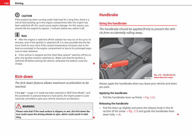
166 Driving
CAUTIONIf the engine has been running under high load for a long time, there is arisk of heat building up in the engine compartment after the engine hasbeen switched off; this could cause engine damage. For this reason, youshould idle the engine for approx. 2 minutes before you switch it off.
Note● After the engine is switched off the radiator fan may run on for up to 10minutes, even if the ignition is switched off. It is also possible that the fanturns itself on once more if the coolant temperature increases due to theheat accumulated in the engine compartment or due to its prolonged expo-sure to solar radiation.
● If the vehicle is stopped and the Start-Stop system* switches off the en-gine, the ignition remains switched on. Make sure that the ignition isswitched off before leaving the vehicle, otherwise the battery could dis-charge.
Kick-down
The kick-down feature allows maximum acceleration to bereached.
If the eco* ⇒ page 212 mode has been selected in SEAT Drive Mode*, andthe accelerator is pressed beyond a hard point, the engine power is auto-matically controlled to give your vehicle maximum acceleration.
WARNING
Please note that if the road surface is slippery or wet, the kick-down fea-ture could cause the driving wheels to spin, which could result in skid-ding.
Handbrake
Using the handbrake
The handbrake should be applied firmly to prevent the vehi-cle from accidentally rolling away.
Fig. 119 Handbrake be-tween the front seats
Always apply the handbrake when you leave your vehicle and whenyou park.
Applying the handbrake
– Pull the handbrake lever up firmly ⇒ Fig. 119.
Releasing the handbrake
– Pull the lever up slightly and press the release knob in the di-rection of the arrow ⇒ Fig. 119 and guide the handbrake leverdown fully ⇒ .
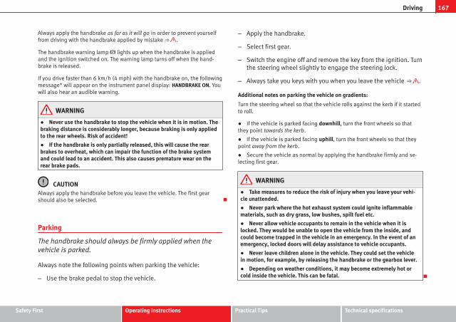
167Driving
Always apply the handbrake as far as it will go in order to prevent yourselffrom driving with the handbrake applied by mistake ⇒ .
The handbrake warning lamp lights up when the handbrake is appliedand the ignition switched on. The warning lamp turns off when the hand-brake is released.
If you drive faster than 6 km/h (4 mph) with the handbrake on, the followingmessage* will appear on the instrument panel display: HANDBRAKE ON. Youwill also hear an audible warning.
WARNING
● Never use the handbrake to stop the vehicle when it is in motion. Thebraking distance is considerably longer, because braking is only appliedto the rear wheels. Risk of accident!
● If the handbrake is only partially released, this will cause the rearbrakes to overheat, which can impair the function of the brake systemand could lead to an accident. This also causes premature wear on therear brake pads.
CAUTIONAlways apply the handbrake before you leave the vehicle. The first gearshould also be selected.
Parking
The handbrake should always be firmly applied when thevehicle is parked.
Always note the following points when parking the vehicle:
– Use the brake pedal to stop the vehicle.
– Apply the handbrake.
– Select first gear.
– Switch the engine off and remove the key from the ignition. Turnthe steering wheel slightly to engage the steering lock.
– Always take you keys with you when you leave the vehicle ⇒ .
Additional notes on parking the vehicle on gradients:
Turn the steering wheel so that the vehicle rolls against the kerb if it startedto roll.
● If the vehicle is parked facing downhill, turn the front wheels so thatthey point towards the kerb.
● If the vehicle is parked facing uphill, turn the front wheels so that theypoint away from the kerb.
● Secure the vehicle as normal by applying the handbrake firmly and se-lecting first gear.
WARNING
● Take measures to reduce the risk of injury when you leave your vehi-cle unattended.
● Never park where the hot exhaust system could ignite inflammablematerials, such as dry grass, low bushes, spilt fuel etc.
● Never allow vehicle occupants to remain in the vehicle when it islocked. They would be unable to open the vehicle from the inside, andcould become trapped in the vehicle in an emergency. In the event of anemergency, locked doors will delay assistance to vehicle occupants.
● Never leave children alone in the vehicle. They could set the vehiclein motion, for example, by releasing the handbrake or the gearbox lever.
● Depending on weather conditions, it may become extremely hot orcold inside the vehicle. This can be fatal.
Safety First Operating instructions Practical Tips Technical specifications

168 Driving
Hill driving assistant*
This function is only included in vehicles with ESC.
The hill driving assistant helps the driver to move off and upwards on a hillwhen the vehicle is stationary.
The system maintains brake pressure for approximately two seconds afterthe driver takes his foot off the brake pedal to prevent the vehicle fromlurching backwards when it is started. During these two seconds, the driverhas enough time to release the clutch pedal and accelerate without vehiclemoving and without having to use the handbrake, making start-up easier,more comfortable and safer.
These are the basic operation conditions:
● being on a ramp or hill/slope,
● closed doors,
● vehicle completely stationary,
● engine running and foot on the brake,
● besides having a gear engaged or being in neutral for manual gearchange and with the selector lever at positions S, D or R in vehicles with au-tomatic gearbox.
This system is also active in reversing uphill.
WARNING
● If you do not start the vehicle immediately after taking your foot offthe brake pedal, the vehicle may start to roll back under certain condi-tions. Depress the brake pedal or use the hand brake immediately.
● If the engine stalls, depress the brake pedal or use the hand brakeimmediately.
● When following a line of traffic uphill, if you want to prevent the vehi-cle from rolling back accidentally when starting off, hold the brake pedaldown for a few seconds before starting off.
NoteThe Official Service or a specialist workshop can tell you if your vehicle isequipped with this system.
Speed warning function
Introduction
The speed warning function can help prevent you exceedinga particular pre-set maximum speed.
The speed warning function will warn the driver if a pre-set maximum speedis exceeded. The system gives an warning buzzer signal if the set speed isexceeded by about 3 km/h. The warning lamp and the driver messageSpeed limit exceeded! will be displayed simultaneously on the instrumentpanel display. The warning lamp switches off when reducing speed be-low the stored maximum limit.
You are recommended to store this speed limit warning if you always wishto be reminded of a particular speed limit. This could be when driving in

169Driving
countries with general speed limits, or if a particular speed should not beexceeded when winter tyres are fitted etc.
Note● Please bear in mind that, even with the speed warning function, it is stillimportant to keep an eye on the vehicle speed with the speedometer and toobserve the legal speed limits.
● The speed limit warning function in the version for several countrieswarns you at a speed of 120 km/h (80 mph). This is a factory-set speed lim-it.
Setting speed limit warning
You can use the radio or the Easy Connect* to set, alter orcancel the speed limit warning.
Vehicles with radio
– Select: SETUP button > control button Driver assistant > Speedwarning.
Vehicles with Easy Connect
– Select: Systems control button or Vehicle systems > Driver assis-tant > Speed warning.
The warning limit can be set from 30 to 240 km/h (20 to 150 mph). The ad-justment is done in 10 km/h (mph) intervals.
Start-Stop system*
Description and operation
The Start-Stop system helps save fuel and reduce CO2 emissions.
In Start-Stop mode, the engine will automatically switch off when the vehi-cle stops, when stopping at traffic lights for example. The ignition remainsswitched on during the stopping phase. The engine automatically switchesback on when required.
As soon as the ignition is switched on, the Start-Stop function is automati-cally activated.
Basic requirements for the Start-Stop mode
● The driver door must be closed.
● The driver must have their seat belt fastened.
● The bonnet must be closed.
● The vehicle must have travelled at more than 4 km/h since the last stop.
● The vehicle cannot be towing a trailer.
WARNING
● Never switch the engine off until the vehicle is stationary. The brakeservo and power steering functions will not be completely covered underwarranty. More force may also be needed to turn the steering wheel or tobrake. As you cannot steer and brake in the normal manner, there is agreater risk of accidents and serious injury.
● Never remove the key from the ignition if the vehicle is in motion.Otherwise, the steering could lock making it impossible to steer the vehi-cle.
Safety First Operating instructions Practical Tips Technical specifications

170 Driving
WARNING (Continued)
● Always take the ignition key with you whenever you leave the vehicle,even temporarily. This is particularly important if there are children inthe vehicle, as they might otherwise be able to start the engine or usepower-operated equipment (e.g. the electric windows), which couldcause injuries.
● To avoid injury, make sure that the Start-Stop system is switched offwhen working in the engine compartment ⇒ page 171.
CAUTIONThe Start-Stop system must always be switched off when driving throughflooded areas ⇒ page 171.
Stop/Start the engine
Vehicles with a manual gearbox
– When the vehicle is stopped, put it into neutral and release theclutch pedal. The engine will switch off. The warning lamp will appear on the instrument panel display.
– When the clutch pedal is pressed the engine will start up again.The warning lamp will switch off.
Vehicles with an automatic gearbox
– Use the foot brake to bring the vehicle to a stop and keep thebrake pedal pressed down with your foot. The engine will switchoff. The warning lamp will appear in the display.
– When you take your foot off the brake pedal the engine will startup again. The warning lamp will switch off.
Additional information related to the automatic gearbox
The engine stops when the selector lever is in the positions P, D, N and S, inaddition to when in manual mode. With the selector lever in position P, theengine will also remain switched off when you take your foot off the brakepedal. In order to start the engine up again the accelerator must be press-ed, or another gear engaged or the brake released.
If the selector lever is placed in position R during the stopping phase, theengine will start up again.
Change from position D to P to prevent the engine from accidentally startingwhen changing and passing by position R.
Note● You can control whether the engine should switch off or not by reducingor increasing the brake force applied. While the vehicle remains stopped,the engine will not stop if the brake pedal is slightly pressed, in traffic jamswith frequent stopping and starting for example. As soon as strong pressureis applied to the brake pedal, the engine will stop.
● In vehicles with manual gearbox, during the stopping phases the brakepedal must remain depressed to prevent the vehicle from moving.
● If the engine stalls in vehicles with manual gearbox, it can be directlystarted up again by immediately pressing the clutch pedal.
General notes
The system can interrupt the Start-Stop mode frequently fordifferent reasons.
The engine does not switch off
Before the stopping phase, the system verifies whether certain conditionsare met. The engine does not switch off, in the following situations for ex-ample:

171Driving
● The engine has not yet reached the minimum required temperature forthe Start-Stop mode.
● The interior temperature selected for the air conditioner has not yetbeen reached.
● The interior temperature is very high/low.
● Defrost function button activated ⇒ page 154.
● The parking aid* is switched on.
● The battery is very low.
● The steering wheel is overly turned or is being turned.
● If there is a danger of misting.
● After engaging reverse gear.
● In case of a very steep gradient.
The indication is shown on the instrument panel display, and in addition,the driver information system* shows, .
The engine starts by itself
During a stopping phase the normal Start-Stop mode can be interrupted inthe following situations: The engine restarts by itself without involvementfrom the driver.
● The interior temperature differs from the value selected on the air condi-tioner.
● Defrost function button activated ⇒ page 154.
● The brake has been pressed several times consecutively.
● The battery is too low.
● High power consumption.
NoteIn vehicles with an automatic gearbox, if the selector lever is placed in posi-tion D, N or S after engaging reverse gear, the vehicle must be driven at aspeed faster than 10 km/h (5 mph) for the system to return to conditions inwhich the engine can be stopped.
Manually switching on/off the Start-Stop system
If you do not wish to use the system, you can switch it offmanually.
Fig. 120 Centre console:Start-Stop system button
– To manually switch on/off the Start-Stop system, press the but-ton . The button symbol remains lit up yellow when the sys-tem is switched off.
NoteThe system is automatically switched on each time the engine is deliberate-ly stopped during a stopping phase. The engine will start automatically.
Safety First Operating instructions Practical Tips Technical specifications

172 Driving
Driver messages on the instrument panel display
Start-Stop system deactivated. Start the engine manually
This driver message is displayed when certain conditions are not met duringthe stopping phase and the Start-Stop system cannot restart the engine.The engine must be started manually.
Start-Stop system: Fault! Function not available
There is a fault in the Start-Stop system. Take the vehicle to a workshop tohave the fault repaired.
Manual gearbox
Changing gears
Fig. 121 Gear shift pat-tern of a 5 or 6-speedmanual gearbox
The position of each of the gears is shown on the gear stick ⇒ Fig. 121.
● Press and hold the clutch pedal to the floor.
● Place the gearbox lever in the required position ⇒ .
● Release the clutch pedal to engage clutch.
In some countries the clutch pedal must be fully pressed down for the en-gine to start.
Selecting reverse gear
● Engage reverse gear only when the vehicle is stopped.
● Press and hold the clutch pedal to the floor ⇒ .
● Move the gearbox lever into the neutral position and press it down.
● Move the gearbox lever completely to the left and then forwards to posi-tion it in reverse gear ⇒ Fig. 121 R .
● Release the clutch pedal to engage clutch.
Changing down gears
While driving, changing down a gear must always be done gradually, i.e. tothe gear directly below and when the engine speed is not too high ⇒ .Changing down while bypassing one or various gears at high speeds or athigh engine speeds can damage the clutch and the gearbox, even if theclutch pedal remains depressed ⇒ .
WARNING
When the engine is running, the vehicle will start to move as soon as agear is engaged and the clutch released. This is also the case with theelectro-mechanical parking brake switched on.
● Never engage reverse gear when the vehicle is moving.
WARNING
If the gear is changed down inappropriately by selecting a gear that istoo low, you may lose control of the vehicle, causing an accident and se-rious injuries.

173Driving
CAUTIONWhen travelling at high speeds or at high engine speeds, selecting a gearthat is too low can cause considerable damage to the clutch and the gear-box. This can also occur if the clutch pedal is pressed and held and it doesnot engage.
CAUTIONTo prevent damage and avoid premature wear, please observe the follow-ing:
● Do not rest your hand on the gear lever while driving. The pressure ap-plied by your hand is transmitted to the gearbox selector forks.
● Always ensure that the vehicle is completely stopped before engagingthe reverse gear.
● Always press the clutch to the floor when changing gears.
● Never hold the vehicle “on the clutch” on hills with the engine on.
Automatic gearbox/DSG automatic gearbox*
Introduction
Your vehicle is equipped with an electronically controlled manual gearbox.Torque between the engine and the gearbox is transmitted via two inde-pendent clutches. They replace the torque converter found on conventionalautomatic gearboxes and allow for smooth, uninterrupted acceleration ofthe vehicle.
The tiptronic system allows the driver to change gears manually if desired⇒ page 178, Changing gears in tiptronic mode*.
Selector lever positions
The selector lever position engaged is highlighted on the display in the in-strument cluster. With the selector lever in the manual gearbox positions G,D, E and S, the engaged gear is also indicated on the display.
P – Parking lock
When the selector lever is in this position, the driven wheels are locked me-chanically. The parking lock must be engaged only when the vehicle is sta-tionary ⇒ .
The interlock button (the button on the selector lever handle) must bepressed in and simultaneously the brake pedal must be depressed beforemoving the selector lever either in or out of position P.
R – Reverse gear
Reverse gear must be engaged only when the vehicle is stationary and theengine is idling ⇒ .
To move the selector lever to position R, the interlock button must be press-ed in and at the same time the brake pedal must be depressed. The reverselights come on when the selector lever is in the R position with the ignitionon.
N – Neutral (idling)
With the selector lever in this position, the gear is in neutral.
D/S – Permanent drive (forward) position
The selector lever in the D/S position enables the gears to be controlled innormal mode (D) or Sport (S). To select Sport mode (S), move the selectorlever backwards. Moving the lever again will select normal mode (D). Theselected driving mode is shown on the instrument panel display.
In normal mode (D), the gearbox automatically selects the best gear ratio.This depends on the engine load, the road speed and the dynamic gearcontrol programme (DCP).
Safety First Operating instructions Practical Tips Technical specifications
174 Driving
Sport mode (S) must be selected for a sporty driving style. This settingmakes use of the engine's maximum power output. When accelerating thegear shifts will be noticeable.
The brake pedal must be pressed when moving the selector lever from D/Sto N if the vehicle is stationary or at speeds below 5 km/h ⇒ .
Under certain circumstances (e.g. when driving in mountains) it can be ad-vantageous to switch temporarily to tiptronic mode ⇒ page 178, in order tomanually select gear ratios to suit the driving conditions.
WARNING
● Take care not to accidentally press the accelerator pedal when the ve-hicle is stopped. The vehicle could otherwise start moving immediately(in some cases even if the parking brake is engaged) resulting in the riskof an accident.
● Never move the selector lever to R or P when driving. Failure to do socould result in an accident.
● With the selector lever in any position (except P) the vehicle must al-ways be held with the foot brake when the engine is running. This is be-cause an automatic gearbox still transmits power even when idling, andthe vehicle tends to “creep”. The accelerator pedal must on no accountbe pressed inadvertently when a gear is engaged with the vehicle sta-tionary. The vehicle could otherwise start moving immediately (in somecases even if the parking brake is engaged) resulting in the risk of an ac-cident.
● While you are selecting a gear and the vehicle is stopped with the en-gine running, do not accelerate. Failure to do so could result in an acci-dent.
WARNING (Continued)
● As a driver you should never leave your vehicle if the engine is run-ning and a gear is engaged. If you have to leave your vehicle while theengine is running, you must apply the handbrake and engage the parkinglock (P).
● To avoid accidents, apply the handbrake and put the selector lever inposition P before opening the bonnet and working on the vehicle withthe engine running. Please always observe the important safety warn-ings ⇒ page 251, Working on components in the engine compartment.
Note● If the selector lever is moved accidentally to N when driving, release theaccelerator and let the engine speed drop to idling before selecting gearrange D or S again.
● Should the power supply to the selector lever be interrupted in posi-tion P, the selector lever will be locked. If this should happen the manualrelease can be used ⇒ page 182.

175Driving
Selector lever lock
The selector lever lock prevents gears from being engagedinadvertently, so that the vehicle is not set in motion unin-tentionally.
Fig. 122 Selector leverlock
The selector lever lock is released as follows:
– Switch the ignition on.
– Press the brake pedal and at the same time press in the inter-lock button.
Automatic selector lever lock
With the ignition switched on, the selector lever is locked in the positions Pand N. The brake pedal must be pressed to release the lever while pressingthe release button if the selector lever is in the position P. As a reminder forthe driver, with the lever in positions P or N the following message will beshown on the display:
When stationary, apply footbrake while selecting a gear.
The selector lever lock only works if the vehicle is stationary or driving atspeeds up to 5 km/h. At higher speeds the selector lever lock in the N posi-tion is disengaged automatically.
The selector lever lock is not engaged if the selector lever is moved quicklythrough position N (e.g. when shifting from R to D). This makes it possible,for instance, to rock the vehicle backwards and forwards if it is stuck. Theselector lever lock engages automatically if the brake pedal is not de-pressed and the lever is in position N for more than about two seconds.
Interlock button
The interlock button on the selector lever handle prevents the driver frominadvertently engaging certain gears. Press the button in to disengage theselector lever lock. The selector lever positions in which the interlock buttonhas to be pressed are shown in the illustration, highlighted in colour⇒ Fig. 122.
Safety interlock for ignition key
Once the ignition has been turned off, the key may be removed only if thegear selector is in position P. While the key is not in the ignition, the selec-tor lever is locked in position P.
Safety First Operating instructions Practical Tips Technical specifications

176 Driving
Note● If the selector lever lock does not engage, there is a fault. The transmis-sion is interrupted to prevent the vehicle from accidentally moving. Followthe procedure below in order for the selector lever lock to engage again:
– With a 6-speed gearbox: press the brake pedal and release it again.
– With a 7-speed gearbox: press the brake pedal. Move the selector lev-er to position P or N and subsequently engage a gear.
● Despite a gear being engaged, the vehicle does not move forwards orback. Proceed to the next mode:
– When the vehicle does not move in the required direction, the systemmay not have the gear range correctly engaged. Press the brake pedaland engage the gear range again.
– If the vehicle still does not move in the required direction, there is asystem malfunction. Seek specialist assistance and have the systemchecked.
Driving tips
The gearbox changes gear ratios automatically as the vehi-cle moves.
The engine can only start with the selector lever in the position P orN. At low temperatures, below -10 °C (50 °F), the engine can onlystart with the selector lever in the position P.
Starting the vehicle
– Press and hold the brake pedal.
– Press and hold the interlock button (the button in the selectorlever handle), move the selector lever to the desired position,for instance D ⇒ page 173, and release the interlock button.
– Wait for the gearbox to engage the gear (a slight movement canbe felt).
– Release the brake and press the accelerator ⇒ .
Stopping briefly
– Apply the foot brake to hold the vehicle when stationary (for in-stance at traffic lights). Do not press the accelerator.
Stopping/Parking
If the driver door is opened and the selector lever is not in positionP, the vehicle could move. Driver message: Gear change: selectorlever in drive position! will be displayed. Additionally, a buzzer willsound.
– Press and hold the brake pedal ⇒ .
– Apply the handbrake.
– Move the selector lever to position P.
Holding the car on a hill
– Always apply the brake pedal firmly to prevent the vehicle from“moving backwards; if necessary, apply the handbrake” ⇒ .Do not try to stop the vehicle “rolling back” by increasing theengine speed when a gear is engaged (pressing the accelera-tor) ⇒ .
Moving off uphill in vehicles without Hill start assistant*
– Apply the handbrake.
– Once you have engaged a gear press the accelerator carefullyand disengage the handbrake.

177Driving
Moving off uphill in vehicles with Hill start assistant*
– Once you have engaged a gear, release the footbrake and pressthe accelerator ⇒ page 168, Hill driving assistant*.
Driving down hills: In some situations (on mountain roads or when towing atrailer or caravan) it can be advantageous to switch temporarily to the man-ual gearbox programme so that the gear ratios can be selected manually tosuit the driving conditions ⇒ .
On level ground it is sufficient to move the selector lever to position P. Onslopes, first engage the parking brake and then put the selection lever intothe P position. This avoids overloading the locking mechanism and it will beeasier to move the selector lever from position P.
WARNING
● As a driver you should never leave your vehicle if the engine is run-ning and a gear is engaged. If you have to leave your vehicle while theengine is running, you must apply the handbrake and engage the parkinglock P.
● If the engine is running and a gear is engaged (D/S or R) or the vehi-cle is in tiptronic mode, you will need to hold the car with the footbrake.Otherwise, the car will creep forwards as the power transmission is notfully interrupted even when the engine is idling.
● Take care not to accidentally press the accelerator pedal when the ve-hicle is stopped. The vehicle could otherwise start moving immediately(in some cases even if the parking brake is engaged) resulting in the riskof an accident.
● While you are selecting a gear and the vehicle is stopped with the en-gine running, do not accelerate. Failure to do so could result in an acci-dent.
● Never move the selector lever to R or P when driving: this could resultin an accident!
WARNING (Continued)
● Before you drive down a steep gradient, reduce your speed and usetiptronic to select a low gear.
● Never allow the brake to rub and do not use the brake pedal too oftenor for long periods. Constant braking causes overheating in the brakes.This could significantly reduce braking power, increase braking distanceor even result in the total failure of the brake system.
● To avoid rolling back on gradients always hold the vehicle with thefootbrake or handbrake if you have to stop.
CAUTION● If you stop the vehicle on a gradient, do not attempt to stop it from roll-ing by depressing the accelerator when a gear has been selected. Thiscould cause overheating and damage the automatic gearbox. Apply thehandbrake firmly or press the brake pedal in order to prevent the vehiclefrom rolling back.
● If you allow the car to roll with the selector lever in position N with theengine switched off, the automatic gearbox will be damaged as it will not belubricated.
● In certain driving situations or traffic conditions, such as frequentlystarting, prolonged “creeping” of the vehicle or traffic jams with continuousstoppages, the gearbox could overheat causing damage! If the warninglamp lights up, stop the vehicle as soon as possible and wait for thegearbox to cool ⇒ page 181.
● In certain driving situations or traffic conditions, such as frequentlystarting, prolonged “creeping” of the vehicle or traffic jams with continuousstoppages, the gearbox could overheat causing damage! If the warninglamp lights up, stop the vehicle as soon as possible and wait for thegearbox to cool ⇒ page 182.
Safety First Operating instructions Practical Tips Technical specifications

178 Driving
Downhill speed control*
The downhill speed control function helps the driver whendriving down steep gradients.
Downhill speed control is activated when the selector lever is in D/S andthe driver applies the foot brake. The automatic gearbox automatically en-gages a lower gear that is suitable for the slope. The downhill speed controlfunction attempts to maintain the speed at which the vehicle was travellingwhen the foot brake was applied (subject to the laws of physics and techni-cal drive limitations). It may be necessary to adjust the speed again usingthe foot brake in certain situations. Given that the downhill speed controlcan only change down to 3rd gear, on very steep descents the tiptronicmode may be required. In this case, manually reduce the tiptronic to 2nd or1st gear to use the engine brake and reduce the charge on the brakes.
Downhill speed control is deactivated as soon as the road levels out againor you press the accelerator pedal.
On vehicles with cruise control system* ⇒ page 184, downhill speed con-trol is activated when you set a cruising speed.
WARNING
The downhill speed control cannot defy the laws of physics. Therefore,speed cannot be maintained constant in all situations. Always be pre-pared to use the brakes!
Changing gears in tiptronic mode*
The tiptronic gives the driver the option to change gearsmanually.
Fig. 123 Centre console:changing gear with Tip-tronic
Fig. 124 Steering wheel:automatic gearbox levers
Changing gear manually with the selector lever
It is possible to change to tiptronic mode, both when the vehicle isstopped and while driving.

179Driving
– To switch to tiptronic mode, move the selector lever from posi-tion D/S to the right. As soon as the change is made, the selec-tor lever will be shown in the position G (i.e. G4 means that 4thgear is engaged) on the instrument panel display.
– Move the selector lever forwards + to select a higher gear⇒ Fig. 123.
– Move the selector lever backwards - to select a lower gear.
Changing gear manually with the gearshift paddles*
The gearshift paddles can be used when the selector lever is in theposition D/S or G.
– Press the gearshift paddle + to select a higher gear⇒ Fig. 124.
– Press the gearshift paddle - to select a lower gear.
– With the selector lever in position D/S, if no paddle is operatedduring a short period of time, the gearbox control systemswitches back to automatic mode. To switch to permanent man-ual gear change using the gearshift paddles, move the selectorlever from position D/S to the right.
When accelerating, the gearbox automatically shifts up into the next gearshortly before the maximum engine speed is reached.
If you select a lower gear, the automatic gearbox will not shift down untilthere is no risk of overrevving the engine.
When the kick-down feature is used, the gearbox shifts down to a lowergear, depending on road speed and engine speed.
Kick-down feature
The kick-down feature allows maximum acceleration to bereached.
When the accelerator pedal is pressed right down past the point of resist-ance at full throttle, the gearbox will shift down to a lower gear, dependingon road speed and engine speed. The upshift to the next higher gear is de-layed until the engine reaches maximum rpm.
WARNING
Please note that if the road surface is slippery or wet, the kick-down fea-ture could cause the driving wheels to spin, which could result in skid-ding.
Launch Control Programme1)
The Launch control programme enables maximum accelera-tion.
Important: the engine must have reached operating temperatureand the steering wheel must not be turned.
The engine speed for “launch control” is different in petrol and die-sel engines. To use the launch-control you must disconnect the an-ti-slip regulation (ASR) through the Easy Connect system in themenu ⇒ page 79. The warning lamp will stay switched on or will
1) Valid for vehicles: with Launch Control/6-Speed DSG with diesel engines superior to 125kW and petrol engines superior to 140 kW.
Safety First Operating instructions Practical Tips Technical specifications

180 Driving
flash slowly depending on whether or not the vehicle has a driverinformation system*1).
– When the engine is running, switch off the traction control(ASR)1) 2).
– Move the selector lever to position “S” or tiptronic, or select thedriving mode Sport from the SEAT Drive Mode* ⇒ page 211.
– Press the brake pedal firmly with your left foot and hold it downfor at least one second.
– With your right foot, press the accelerator down to the full throt-tle or kick-down position. The engine speed will stabilise at ap-prox. 3200 rpm (petrol engine) or approx. 2000 rpm (diesel en-gine).
– Take your left foot off the brake pedal.
WARNING
● Always adapt your driving style to the traffic conditions.
● Only use the “Launch control programme” when road and traffic con-ditions permit, and make sure the way in which you drive and acceleratethe vehicle does not inconvenience or endanger other road users.
WARNING (Continued)
● Make sure that the ESC remains switched on. Please note that whenthe ASR and ESC are deactivated, the wheels may start to spin, causingthe vehicle to lose grip. Risk of accident!
● After putting the vehicle into gear, the “sport” mode of the ESCshould be deactivated again by briefly pressing the OFF button.
Note● After using the “Launch control programme”, the gearbox temperaturemay have increased considerably. In this case, the programme could be dis-abled for several minutes. The programme can be used again after the cool-ing phase.
● Accelerating with the “Launch control programme” places a heavy loadon all parts of the vehicle. This can result in increased wear and tear.
Inertia mode
The inertia mode enables the kinetic energy of the vehicle to beharnessed enabling certain stretches to be driven without usingthe accelerator. This enables fuel to be saved. Use the inertia modeto “let the vehicle roll” before, for example, arriving in a town.
Switching on inertia mode
Important: selector lever must be in position D, gradients below12 %.
1) On vehicles with the driver information system, the ESC lamp lights up permanently andthe corresponding text message Stability control deactivated (temporary) appears on the in-strument panel to indicate the deactivation status.
2) Vehicles without driver information system: the warning lamp flashes slowly/Vehicles withdriver information system: the warning lamp stays on.

181Driving
– Select Eco mode ⇒ page 211 once in SEAT Drive Mode*.
– Take your foot off the accelerator.
The driver message Inertia will be displayed. At speeds higherthan 20 km/h (12 mph), the gearbox will automatically disengageand the vehicle will roll freely, without the effect of the enginebrake. While the vehicle rolls, the engine runs at idling speed.
Stopping inertia mode
– Press the brake or the accelerator pedal.
To make use of the braking force and switch off the engine again,simply press the brake pedal briefly.
Applying both the inertia mode (= prolonged section with less energy) andthe switching off using inertia (= shorter section without the need for fuel)facilitates improved fuel consumption and emission balance.
WARNING
● If the inertia mode has been switched on, take into account, when ap-proaching an obstacle and releasing the accelerator pedal, that the vehi-cle will not decelerate in the usual manner: risk of accident!
● When using inertia mode while travelling down hills, the vehicle canincrease speed: risk of accident!
● If other users drive your vehicle, warn them about inertia mode.
Note● Inertia mode is only available in eco driving mode (SEAT Drive Mode*).
● The driver message Inertia is only displayed with the current consump-tion. In inertia mode the gear will no longer be displayed (for example: “E”will appear in place of “E7”).
● On downhill sections with gradients above 15 %, the inertia mode willautomatically be switched off temporarily.
Backup programme
A backup programme is in place if a fault should occur in thecontrol system.
If all the positions of the selector lever are shown over a light backgroundon the instrument panel display, there is a system fault and the automaticgearbox will operate in with the backup programme. When the backup pro-gramme is activated, it is possible to drive the vehicle, however, at lowspeeds and within a selected range of gears. In some cases driving in re-verse gear may not be possible.
CAUTIONIf the gearbox operates with the backup programme, take the vehicle to aspecialised workshop and have the fault repaired without delay.
Clutch
Clutch overheated! Stop the vehicle!
The clutch has overheated and could be damaged. In order to prevent thetemperature from increasing again and so that the clutch is cooled, stop the
Safety First Operating instructions Practical Tips Technical specifications

182 Driving
vehicle and wait for the gearbox to cool down with the selector lever in posi-tion P and the engine running at idling speed. If the warning does notswitch off, do not continue driving. Seek specialist assistance. Failure to doso could cause considerable damage to the gearbox. When the warningswitches off, the fault should be corrected by a specialised workshop with-out delay.
Faults in the gearbox
Gearbox: Fault! Stop the vehicle and place the lever in the position P.
There is a fault in the gearbox. Stop the vehicle in a safe place and do notcontinue driving. Seek specialist assistance.
Overheated clutch! Stop the vehicle!
The clutch has overheated and could be damaged. Stop the vehicle andwait for the gearbox to cool with the engine at idling speed and the selectorlever in position P. When the warning lamp and the driver message switchoff, have the fault corrected by a specialised workshop without delay. If thewarning lamp and the driver message do not switch off, do not continuedriving. Seek specialist assistance.
Gearbox: System fault! You may continue driving.
Have the fault corrected by a specialised workshop without delay.
Gearbox: System fault! You can continue driving with restrictions. Re-verse gear disabled.
Take the vehicle to a specialised workshop and have the fault repaired with-out delay.
Gearbox: System fault! You can continue driving in D until switching offthe engine
Stop the vehicle in a safe place well away from moving traffic. Seek special-ist assistance.
Gearbox: too hot. Adapt your driving accordingly
Continue driving at moderate speeds. When the warning lamp switches off,you can continue driving in a normal manner.
Gearbox: press the brake and engage a gear again.
If the fault was caused by a gearbox with a high temperature, this drivermessage will be displayed when the gearbox has cooled again.
Manual release of the selector lever
The selector lever can be released manually if the electricalpower supply should fail.
Fig. 125 Selector lever:manual release from po-sition P
The manual release mechanism is located under the selector leverconsole on the right side. Releasing the selector lever requires a

183Driving
certain degree of practical skill. We therefore advise you to obtainprofessional assistance.
A screwdriver will be needed to carry out the manual release. Usethe flat part of the screwdriver blade ⇒ page 274.
Removing the cover from the selector lever
– Apply the handbrake ⇒ to ensure that the car does notmove.
– Carefully pull the corners of the selector lever boot and fold upthe selector lever boot (inside out) by hand.
Releasing the selector lever
– Using a screwdriver, press and hold the yellow unlocking tabsideways ⇒ Fig. 125.
– Now press the interlock button on the selector lever A andmove the selector lever to position N.
– After carrying out the manual release, attach the selector leverboot on the gearbox console again.
If the power supply should ever fail (discharged battery, etc.) and the vehi-cle has to be pushed or towed, the selector lever must first be moved to po-sition N. This is possible after operating the manual release mechanism.
WARNING
The selector lever may be moved out of position P only when the hand-brake is firmly applied. If this does not work, secure the vehicle with thebrake pedal. On a slope the vehicle could otherwise start to move inad-vertently after shifting the selector lever out of position P - accident risk!
Safety First Operating instructions Practical Tips Technical specifications

184 Driver assistance systems
Driver assistance systems
Cruise control system (CCS)*
Introduction
The cruise control system (CCS) is able to maintain the set speed from 20km/h (15 mph).
A constant speed is maintained using the engine power control or by apply-ing the active brake ⇒ .
Additional information and warnings:
● Change gear ⇒ page 173.
● Accessories and technical modifications ⇒ page 272.
WARNING
Use of the cruise control could cause accidents and severe injuries if it isnot possible to drive at a constant speed maintaining the safety distance.
● Do not use the cruise control in heavy traffic, if the distance from thevehicle in front is insufficient, on steep roads, with several bends or inslippery circumstances (snow, ice, rain or loose gravel), or on floodedroads.
● Never use the CCS when driving off-road or on unpaved roads.
● Always adapt your speed and the distance to the vehicles ahead inline with visibility, weather conditions, the condition of the road and thetraffic situation.
● To avoid unexpected operation of the cruise control system, turn it offevery time you finish using it.
WARNING (Continued)
● It is dangerous to use a set speed which is too high for the prevailingroad, traffic or weather conditions.
● When travelling down hills, the CCS cannot maintain a constantspeed. The vehicle tends to accelerate under its own weight. Select alower gear or use the foot brake to slow the vehicle.
Warning and control lamp
Fig. 126 Instrument panel display: CCS status indications

185Driver assistance systems
Control lamp
lights up Possible cause
Cruise control is active
Several warning and control lamps should light up for a few seconds whenthe ignition is switched on, signalling that the function is being verified.They will switch off after a few seconds.
Displayed on the CCS screen
Status Fig. 126:
CCS temporarily switched off. The set speed is displayed in small fig-ures.
System error. Contact a specialised workshop.
CCS switched on. The speed memory is empty.
The CCS is switched on. The set speed is displayed in large figures.
WARNING
If the warning lamps and messages are ignored, the vehicle may stall intraffic, or may cause accidents and severe injuries.
● Never ignore the warning lamps or text messages.
CAUTIONFailure to heed the control lamps and text messages when they appear mayresult in faults in the vehicle.
A
B
C
D
Safety First Operating instructions Practical Tips Technical specifications

186 Driver assistance systems
Operating the cruise control system*
Fig. 127 On the left ofthe steering column:switches and controls foroperating the CCS
Fig. 128 On the left ofthe steering column:Third 6-position lever foroperating the CCS
effectPosition of the switch, operating the switch on the turn signal lever ⇒ Fig. 127, orby using the third lever ⇒ Fig. 128
Action
Switching on the CCSMove the switch 1 on the turn signal lever to the ON position, or move the thirdlever to the ON position.
The system is switched on. The system doesnot maintain the speed because there is stillno speed set.
Activating the CCSPress the SET button on the turn signal lever or press the SET button on the thirdlever.
The current speed is stored and maintained.
Temporarily switching offthe CCS
Move the switch 1 on the turn signal lever to the CANCEL position. Move thethird lever to the CANCEL position and release it.OR: Apply the foot brake.
The cruise control system is switched offtemporarily. The speed setting will remainstored.
Switching on the CCS againPress the button 3 on the turn signal lever to the RES/+ position, or move thethird lever to the RESUME position and release it.
The stored speed will be saved and will reg-ulate again.

187Driver assistance systems
effectPosition of the switch, operating the switch on the turn signal lever ⇒ Fig. 127, orby using the third lever ⇒ Fig. 128
Action
Increasing the storedspeed (during CCS setting)
Depending on equipment fitted:– briefly press the button 3 on the turn signal lever in the RESzone– or briefly move the third lever to the RESUME position to increase speed by1 km/h (1 mph)– or move the third lever upwards with SPEED+ to increase the speed by 10 km/h(10 mph) and store it– or continuously press the button 3 on the turn signal lever in the RESzone– or move the third lever upwards with SPEED+ continuously– or move the third lever to the RESUME position and hold it to continuously in-crease the speed and store it.
The vehicle accelerates actively until it rea-ches the new stored speed.
Increasing the storedspeed
When the CCS is in the ON position, but DEACTIVATED, the speed setting can beincreased with SPEED+ by 10 km/h (10 mph).
The vehicle accelerates actively until it rea-ches the new stored speed.
Reducing the stored speed(during CCS setting)
Depending on equipment fitted:– briefly press the button 3 on the turn signal lever in the SET zone to reducespeed by 1km/h (1mph)– or briefly move the third lever to the SET position to reduce the speed by 1 km/h(1 mph)– or move the third lever downwards with SPEED– to reduce the speed by 10 km/h (10 mph) and store it– or continuously press the button 3 on the turn signals lever in the SETzone– or press and hold the button SET on the third lever to reduce speed contin-uously– or move the third lever downwards (SPEED–) continuously and store it.
Speed is reduced without braking, by inter-rupting the accelerator until reaching thenew stored speed.
Setting a lower speedWhen the CCS is in the ON position, but DEACTIVATED, the speed setting can bereduced with SPEED– by 10 km/h (10 mph).
The system is switched off. The stored speedis deleted.
Switching off the CCSMove the switch 1 to the OFF position.OR: move the third lever to the OFF position.
Speed is reduced without intervening in thebraking system, by interrupting the accelera-tor until reaching the new stored speed.
The value indicated in the table in brackets (in mph, miles per hour) onlyrefers to instrument panels with indications in miles.
Changing gear in CCS mode
The CCS decelerates as soon as the clutch pedal is pressed, interveningagain automatically after a gear is engaged.
Safety First Operating instructions Practical Tips Technical specifications

188 Driver assistance systems
Travelling down hills with the CCS
When travelling down hills the CCS cannot maintain a constant speed. Slowthe vehicle down using the brake pedal and reduce gears if required.
Automatic off
The cruise control system (CCS) is switched off automatically or temporarily:
● If the system detects a fault that could affect the working order of theCCS.
● If you press and maintain the accelerator pedal for a certain time, driv-ing faster than the stored speed.
● If the dynamic driving control systems intervene (i.e. ASR or ESC).
● If the airbag is triggered.

189Driver assistance systems
Adaptive cruise control (ACC)*
Introduction
Fig. 129 Detection area
Adaptive cruise control (ACC) is an extension of vehicle cruise control (GRA)⇒ .
The ACC function allows the driver to establish a cruising speed between 30and 160 km/h (18 and 100 mph), as well as the time distance from the ve-hicle ahead. The ACC function will adapt to the vehicle's adaptive cruisespeed at all times, maintaining a safety distance from the vehicle ahead.
The ACC function is based on a radar sensor that can measure the distanceto vehicles ahead.
If the vehicle is equipped with automatic gearbox, the ACC may brake it un-til it stops completely if the vehicle ahead stops.
Request for driver intervention
During driving, the ACC is subject to certain limitations inherent in the sys-tem. In other words, in certain circumstances the actual driver will have tocontrol speed and distance with regard to other vehicles.
In this case, the instrument panel display will tell the driver to intervene bypressing the brake pedal, and a warning sound will go off ⇒ page 191.
Additional information and warnings:
● SEAT information system ⇒ page 73
● Easy Connect system ⇒ page 79
● Cruise control system (CCS) ⇒ page 184
● Front Assist ⇒ page 202
● Lane Assist ⇒ page 207
● Accessories, parts replacement, repairs and modifications ⇒ page 272
WARNING
The intelligent technology in the ACC cannot overcome the system's ownlimitations or change the laws of physics. If used negligently or uninten-tionally it may cause a serious accident and serious injury. The system isnot a replacement for driver awareness.
● Always adapt speed and safety distance to the vehicle ahead accord-ing to visibility, weather, road and traffic conditions.
● Do not use the ACC in conditions of poor visibility, on steep roads,with several bends or in slippery circumstances such as snow, ice, rain orloose gravel or on flooded roads.
● Never use the ACC when driving off-road or on unpaved roads. TheACC has only been designed for use on paved roads.
● The ACC does not react on approaching a stationary obstacle, such asthe end of a traffic jam or a broken-down vehicle or a vehicle stopped attraffic lights.
● The ACC does not react during driving to people or animals or vehi-cles changing lane or approaching in the opposite direction in the samelane.
● If the ACC does not reduce speed enough, apply the foot brake imme-diately.
Safety First Operating instructions Practical Tips Technical specifications

190 Driver assistance systems
WARNING (Continued)
● If the vehicle continues to move following a driver intervention re-quest, apply the foot brake.
● If the instrument panel display shows a driver intervention request,adjust the distance yourself.
● The driver must be ready to accelerate or brake by him- or herself atany time.
CAUTIONIf you have the impression that the radar sensor is damaged, disconnect theACC. This will prevent possible damage. In this case have it adjusted.
● A radar sensor repair requires specialist knowledge and special tools.SEAT recommends visiting a SEAT dealership for this.
Note● If the ACC does not operate as described in this chapter, do not use ituntil it has been checked by a specialised workshop. SEAT recommends vis-iting a SEAT dealership for this.
● The maximum speed with the ACC switched on is limited to 160 km/h(100 mph).
● When the ACC is switched on, strange noises may be heard during auto-matic braking.
Messages on the display, control and warning lamps
Fig. 130 On the instrument panel display: (A) ACC temporarily inactive, vehicle detec-ted ahead, temporary distance adjusted. (B) ACC active, vehicle detected ahead, a tem-porary distance is adjusted.
Status display
Messages on the display ⇒ Fig. 130:
Vehicle ahead, the ACC is inactive.
Distance margin selected, the ACC is inactive.
Vehicle detected ahead. The ACC is active.
Adjustment of the temporary distance with regard to the vehicle aheadwith a set speed.
Temporary distance adjusted with regard to the vehicle ahead with aset speed.
1
2
3
4
5

191Driver assistance systems
Warning and control lamps
Lightsup
Possible cause ⇒ Solution
A speed reduction by the ACC tomaintain distance with the ve-hicle ahead is not enough.
Brake! Use the foot brake!Driver intervention necessary:
The ACC is not currently availa-blea).
With the vehicle stationary,switch the engine off and backon again. Check the radar sen-sor visually (in case it is dirty,has ice or has been knocked).If it is still unavailable, refer toa specialised workshop tohave the system inspected.
The ACC is active. No vehicle isdetected ahead. The set speedremains constant.
–
If the symbol is white: the ACCis active. A vehicle in front hasbeen detected. The ACC adjuststhe speed and the distancefrom the vehicle ahead. –If the symbol is grey: the ACC isnot active. The system isswitched on, but it is not con-trolling.
The ACC is active. –
a) The symbol is in colour on the instrument panel with colour display.
Some warning and control lamps will light up briefly when the ignition isswitched on to check certain functions. They will switch off after a few sec-onds.
WARNING
Failure to heed the warning lamps when they light up and the corre-sponding messages may result in damage to the vehicle and serious in-jury.
● Never ignore the warning lamps or messages.
CAUTIONFailure to heed the control lamps when they light up and the correspondingmessages may result in damage to the vehicle.
NoteWhen the ACC is connected, the instrument panel display messages may behidden by messages pertaining to other functions, such as an incomingcall.
Radar sensor
Fig. 131 On the frontbumper: radar sensor.
Safety First Operating instructions Practical Tips Technical specifications

192 Driver assistance systems
On the front bumper there is a radar sensor to detect traffic conditions⇒ Fig. 131 1 . This sensor can detect vehicles driving ahead at a distanceof up to approx. 120 m.
The radar sensor's visibility may be impaired by dirt, such as mud or snow,or by environmental influences, such as rain or water mist. In this case theadaptive cruise control (ACC) does not work. The following message isshown in the instrument panel display: ACC: Sensor without visibility!. If nec-essary, clean the radar sensor ⇒ .
When the radar sensor works properly again, the ACC will be automaticallyavailable again. The message on the instrument panel display will go offand the ACC can be switched on again.
ACC operation may be affected by a heavy reverse reflection of the radar sig-nal. This may occur, for example, in a closed car park or due to the presenceof metal objects (e.g. rails on the road or the panels used on work sites).
The area ahead of and behind the radar sensor should not be covered withadhesives, additional headlights or the likes, as this may have a negativeeffect on ACC operation.
If structural modifications are made to the vehicle, e.g., if the suspension islowered or the front spoiler is modified, ACC operation may be affected. Thisis why structural modifications should only be assigned to specialised work-shops. SEAT recommends visiting a SEAT dealership for this.
If the front part of the vehicle is repaired incorrectly, the radar sensor mightlose its setting and ACC operation would be affected. This is why repair jobsshould only be assigned to specialised workshops. SEAT recommends visit-ing a SEAT dealership for this.
CAUTIONIf you have the impression that the radar sensor is damaged or has lost itssetting, disconnect the ACC. This will prevent possible damage. In this casehave it adjusted.
● The sensor may lose its settings if it is knocked, for example, during aparking manoeuvre. This may compromise the system's efficacy or lead it toswitch off.
● A radar sensor repair requires specialist knowledge and special tools.SEAT recommends visiting a SEAT dealership for this.
● Snow should be removed with a brush, while ice should be removedwith a solvent-free anti-ice aerosol.

193Driver assistance systems
Using the adaptive cruise control (ACC)
Fig. 132 On the left ofthe steering column:Third lever for using theadaptive cruise control.
Fig. 133 On the left ofthe steering column:Third lever for using theadaptive cruise control.
When the adaptive cruise control (ACC) is switched on, the green controllamp comes on and the display shows the set speed and ACC status⇒ Fig. 130.
Conditions for the adaptive cruise control to be switched on
● The selector lever should be turned to position D or S, or in the Tiptronicselection gear. In case of manual gearbox, any forward gear should be en-gaged, except first gear.
● In vehicles with manual gearbox, if there is no set speed, you shoulddrive at less than 30 km/h (18 mph).
Speed control
When the ACC is switched on, speed can be programmed and adjusted. Theset speed may differ from the vehicle's actual speed if the distance is cur-rently being controlled.
What functions can be used?
If you switch on adaptive cruise control you can programme the currentspeed as “control speed”.
While driving, the control can be interrupted at any time and the speedmodified as well.
The following settings can also be made:
● Distance
● Driving programme
● Driving mode
Activating/Deactivating
Any speed can be set1) from 30 to 160 km/h (19 and 100 mph).
Switching on adaptive cruise control
● Pull the lever to position 1 ⇒ Fig. 132. ACC standby will appear on theinstrument panel display.
1) Speed limits are different in each country and depend on the unit shown on the speedome-ter.
Safety First Operating instructions Practical Tips Technical specifications

194 Driver assistance systems
Programming speed and switching on control
● To store the current speed press the button SET ⇒ Fig. 133.
● Automatic gearbox: to switch on stationary vehicle control, step on thebrake pedal.
Switching off the adaptive cruise control
● Move the lever to position 0 until it engages. The text ACC: off will bedisplayed.
Altering speed
● To increase or decrease speed, gradually briefly press the lever up/down⇒ Fig. 133.
Any change in the stored speed is shown on the bottom left of the instru-ment panel display.
Adjusting the distance level
The distance according to the speed of the vehicle in front can be adjustedto 5 levels on the Easy Connect system ⇒ page 80.
When the road is wet a greater distance from the vehicle in front should beselected than when the road is dry.
The following distances can be preselected:
● Very short
● Short
● Media
● Long
● Very long
The Easy Connect system can be used to adjust the level of distance appli-cable when the ACC is switched on by means of the button and the func-tion buttons and Driver Assistance ⇒ page 80.
Setting the driving programme
In vehicles with driving mode selection (SEAT Drive Mode), the profile selec-ted may influence acceleration behaviour ⇒ page 211.
The following driving programmes can be selected:
● Normal
● Sport
● Eco
In vehicles without SEAT Drive Mode, acceleration behaviour can be influ-enced by selecting a driving programme on the Easy Connect system usingbutton and the function buttons and Driver Assistance ⇒ page 80.
The following conditions may cause the ACC not to react:
● If the accelerator is pressed down.
● If there is no gear selected
● If the ESC is controlling.
● If the driver unbuckles his/her seat belt.
● If several brake lights on the vehicle or trailer have electrical faults.
● If the vehicle is reversing.
● If you are driving at a speed above approx. 160 km/h (100 mph).
WARNING
There is danger of a rear-end collision if the minimum distance from thevehicle ahead is exceeded and the speed difference between both vehi-cles is so great that speed reduction by the ACC is insufficient. In thiscase, brake immediately with the brake pedal.
● The ACC might not detect all situations correctly.

195Driver assistance systems
WARNING (Continued)
● “Stepping” on the accelerator may lead the ACC not to intervene tobrake. Acceleration by the driver takes priority over action by the activecruise control.
● Always be prepared to use the brakes to halt the vehicle!
● Observe the provisions of the country in question regarding the mini-mum obligatory distance between vehicles.
Note● The stored speed is erased when the ignition or the ACC are switchedoff.
● When the traction control system (ASR) is switched off or the ESC is acti-vated in Sport* (⇒ page 79) mode, the ACC is switched off automatically.
● In vehicles with Start-Stop system, the engine switches off automaticallyduring the ACC halt phase and restarts automatically to begin driving.
Vehicles with an automatic gearbox
If the vehicle is equipped with automatic gearbox, the Adaptive Cruise Con-trol (ACC) may brake it until it stops completely if the vehicle ahead stops.
The ACC will be available for a few seconds. The vehicle will restart autono-mously if the vehicle ahead moves (assistant in line of traffic).
Disconnection criteria
The ACC will switch off if the driver steps on the brake pedal or the driverdoor is opened.
If the vehicle ahead stops for more than 3 seconds, the ACC will also switchoff for safety reasons. In this case the driver should take over and apply thefoot brake.
In the latter case, when the ACC is switched off with the vehicle stationary,the vehicle must be stopped by applying the foot brake; since the car, witha gear engaged, even at idle speed, might move.
Restart the ACC manually.
The ACC can be switched on again by turning the lever to position 2
⇒ Fig. 134.
WARNING
Your vehicle can start up even if there is an obstacle between your ownand the one ahead. Risk of accident!
CAUTION● If your vehicle with adaptive cruise control failed to start as expected,even if the ACC available1) message is shown to the driver, you can start offby briefly stepping on the accelerator.
● The Start-Stop system acts as usual when driving with adaptive cruisecontrol.
1) Not available for the versions of some countries.
Safety First Operating instructions Practical Tips Technical specifications

196 Driver assistance systems
Interrupting cruise control
Fig. 134 On the left ofthe steering column:Third lever for using theadaptive cruise control.
Important: The adaptive cruise control is switched on.
Interrupting cruise control during driving
● Move the lever to position 3 . The driver message ACC standby will bedisplayed. or
● Brake.
● To return to the stored speed, turn the lever to position 2 .
Interrupting cruise control when the vehicle is stationary
Valid for vehicles with automatic gearbox:
● Move the lever to position 3 . The driver message ACC standby will bedisplayed.
● To resume adaptive cruise control, apply the foot brake and turn the lev-er to position 2 .
WARNING
It is dangerous to switch on cruise control and resume the stored speed ifthe road, traffic or weather conditions do not permit. Risk of accident!
Setting the distance
Fig. 135 Control leverfor: Setting the distance
● To indicate the distance currently programmed, briefly press the rockerswitch ⇒ Fig. 135.
● To increase/reduce a level, press the rocker switch again to the right/left. The display in the instrument panel modifies the distance betweenboth vehicles.
If the vehicle approaches another halted vehicle ahead of it, the adaptivecruise control reduces the speed to match the other's and then controls theadjusted distance. If the vehicle in front accelerates, the adaptive cruisecontrol will also accelerate, up to the speed you have programmed.
The greater the speed, the greater the distance in metres should be ⇒ .We recommend the setting Distance 3.
WARNING
The driver is responsible for observing country-specific distance regula-tions.

197Driver assistance systems
Message texts
ACC not available
The system cannot continue to guarantee safe vehicle detection so it isswitched off. The sensor has lost its setting or is damaged. Take the vehicleto a specialised workshop to have the fault repaired.
ACC: not available at the moment. Sensor without visibility
ACC and Front Assist: not available at the moment. Sensor withoutvisibility
This message for the driver is displayed if the visibility of the radar's sensoris impaired, e.g., by leaves, snow, heavy mist or dirt. Clean the sensor.
ACC: not available at the moment. Gradient too steep
The maximum slope has been exceeded, hence it cannot be guaranteedthat the adaptive cruise control will operate safely. The adaptive cruise con-trol cannot be activated
ACC: only available in D, S or M
Select the position of the selector lever D/S or M.
ACC: parking brake applied
The adaptive cruise control is deactivated if the parking brake is applied.The adaptive cruise control is available again if the parking brake is re-leased.
ACC: not available at the moment. Stabilisation control intervention
The message for the driver is shown when the electronic stabilisation con-trol (ESC) intervenes. In this case, the adaptive cruise control will automati-cally be switched off.
ACC: Intervene!
The message for the driver is shown if, when you start up on a gentle slope,the vehicle moves backwards even although the ACC is switched on. Step
on the brake pedal to prevent the vehicle from moving/crashing into anoth-er vehicle.
ACC: speed limit
The message for the driver is shown in vehicles with manual gearbox if thecurrent speed is too low for ACC mode.
The speed you wish to store must be at least 30 km/h. The cruise controlsystem switches off if the speed falls below 20 km/h.
ACC: available as of the 2nd gear
The adaptive cruise control is operational as of the 2nd gear (manual gear-box).
ACC: engine speed
The message for the driver is shown if, when the adaptive cruise control ac-celerates or brakes, the driver does not go up or down a gear in time, whichwould mean either exceeding or not reaching the admissible rpm. The adap-tive cruise control will then be switched off. A warning buzzer goes off.
ACC: clutch pressed down
Vehicles with a manual gearbox: press the clutch pedal for longer to exitcontrol.
Three white dots appear if a setting made with the control lever cannot beexecuted. For example, the adaptive cruise control cannot be switched on ina stationary vehicle when the driver's seatbelt is not fastened.
Door open
Vehicles with automatic gearbox: the adaptive cruise control cannot beswitched on in a stationary vehicle with the door open.
Safety First Operating instructions Practical Tips Technical specifications

198 Driver assistance systems
Switching off adaptive cruise control (ACC) temporarily incertain situations
The adaptive cruise control (ACC) should be switched off in the following sit-uations due to the system's limitations ⇒ :
● When changing lanes, on tight bends, at roundabouts, in the accelera-tion and deceleration lanes on motorways or in road work stretches to pre-vent involuntary acceleration to reach the stored speed.
● When going through a tunnel, as its operation might be affected.
● On roads with several lanes when other vehicles are driving more slowlyin the overtaking lane. In this case, vehicles driving more slowly in the otherlanes would be overtaken on the right.
● In heavy rain, snow or thick mist, as it might not detect the vehicleahead or in certain circumstances it might not detect the vehicle altogether.
WARNING
If the adaptive cruise control is not switched off in the aforementionedsituations, accidents and serious injuries may be caused.
● The ACC should always be switched off in critical situations.
NoteFailure to switch off the ACC in the situations may be an offence.

199Driver assistance systems
Special driving situations
Fig. 136 (A) Vehicle on abend. (B) Motorcyclistdriving ahead out ofrange of the radar sensor.
Fig. 137 (C) Other vehi-cle changing lanes (D)Vehicle turning and an-other one stopped.
The Adaptive Cruise Control (ACC) has certain physical limitations inherentin the system. For example, some of the ACC's reactions, in certain circum-stances, may be unexpected or occur at the wrong time as far as the driveris concerned. Therefore, be on the lookout in case you have to intervene.
For example, the following traffic situations call for the utmost attention:
Deceleration until the vehicle comes to a halt (only vehicles with automaticgearbox)
If the vehicle in front reduces speed and stops, the ACC will do the samewith your own vehicle. After the vehicle has been stopped for approx. 3 sec-onds, the system will warn the driver that he has to take control by means ofan acoustic and visual warning on the instrument panel.
Starting up after a halt phase (only vehicles with automatic gearbox)
After a halt phase, the ACC can start driving automatically as soon as thevehicle ahead begins to move again.
Safety First Operating instructions Practical Tips Technical specifications

200 Driver assistance systems
Overtaking
When the turn signal comes on before overtaking, the ACC accelerates thevehicle automatically and thus reduces the distance between it and the ve-hicle ahead.
When you move into the overtaking lane, if the ACC does not detect any ve-hicle in front it accelerates until it reaches the stored speed and keeps itconstant.
The acceleration can be interrupted at any time by stepping on the brakepedal or pulling back on the lever ⇒ page 193.
Driving through a bend
On entering or coming out of a bend, the radar sensor may no longer detectthe vehicle ahead of it or may react before a vehicle in the adjacent lane⇒ Fig. 136 A. In such situations the vehicle may brake unnecessarily or maycease to react with regard to the vehicle ahead. In this case, the driver hasto act by accelerating or interrupting the braking process by stepping on thebrake pedal or pulling the third lever backwards ⇒ page 193.
Driving in tunnels
When going through tunnels, the radar sensor function may be limited.Switch off the ACC in tunnels.
Narrow vehicles or vehicles not driving straight
The radar sensor can only detect narrow vehicles or those that are not driv-ing straight within its range ⇒ Fig. 136 B. This is particularly applicable tonarrow vehicles such as motorbikes. In these cases, brake yourself as nec-essary.
Vehicles with loads and special accessories
The load and special accessories of other vehicles that jut out over the side,backwards or forward may be outside the range of the ACC.
Switch off the ACC when driving behind vehicles with loads or special acces-sories, as well as when overtaking these vehicles. In these cases, brakeyourself as necessary.
Other vehicles changing lanes
Vehicles changing lanes not far away from the vehicle can only be detectedwhen they fall within the range of the sensors. Consequently, the ACC willtake longer to react ⇒ Fig. 137 C. In these cases, brake yourself if necessary.
Stationary vehicles
During driving, the ACC does not detect stationary objects, such as the endof a jam or damaged vehicles.
If a vehicle detected by ACC turns or moves over and there is another sta-tionary vehicle in front of it, the ACC will not react ⇒ Fig. 137 D. In these ca-ses, brake yourself if necessary.
Vehicles travelling in the opposite direction and vehicles changing lanes
The ACC does not react to vehicles approaching in the opposite direction orvehicles changing lanes.
Metal objects
Metal objects, e.g. rails on the road or the panels used on work sites, mayconfuse the radar sensor and cause wrong reactions in the ACC.
Factors that may affect the operation of the radar sensor
If the operation of the radar sensor were affected by heavy rain, water mist,snow or mud, the ACC is switched off temporarily. The relevant message ap-pears on the instrument panel display. If necessary, clean the radar sensor.
When the radar sensor works properly again, the ACC will be automaticallyavailable again. The message on the instrument panel display will go offand the ACC can be switched on again.
In the event of a heavy reverse reflection of the radar signal, for example, ina closed parking, ACC operation may be affected.
Trailer towing
When driving with a trailer, the ACC controls less dynamically.
201Driver assistance systems
Overheated brakes
If the brakes overheat, for example, after a sharp brake or in long and verysteep descents, the ACC may switch off temporarily. The relevant messageappears on the instrument panel display. In such cases, the cruise controlmight not be switched on.
Once the brake temperature has come down sufficiently, the active cruisecontrol can be switched on again. The message will disappear from the in-strument panel display. If the ACC not available message remains on forquite some time, it means there is a fault. Visit a specialised workshop,SEAT recommends a SEAT dealer.
WARNING
If the message ACC ready to start is shown on the instrument panel dis-play and the vehicle ahead starts up, the vehicle will start automatically.In this case, the radar sensor may not detect possible objects on theroad. This could cause an accident and serious injury.
● Before moving off, check that the road is clear. If necessary, apply thefoot brake.
Safety First Operating instructions Practical Tips Technical specifications

202 Driver assistance systems
Monitoring system Front Assist*
Introduction
The Front Assist Monitoring System helps to avoid rear-end collisions.
The Front Assist can warn the driver in case of a collision hazard, preparethe vehicle for emergency braking in the event of danger, assisting the driv-er in braking and provoking automatic braking.
The Front Assist system is not a replacement for driver awareness.
Additional information and warnings:
● SEAT information system ⇒ page 73
● Easy Connect system ⇒ page 79
● Cruise control system (CCS) ⇒ page 184
● Adaptive Cruise Control (ACC) ⇒ page 189
● Accessories, parts replacement, repairs and modifications ⇒ page 272
Distance warning
If the system detects that safety is compromised because you are drivingtoo close to the vehicle in front, it can warn the driver with an on-screenmessage on the instrument panel when you are driving at a speed betweenapprox. 60 km/h (37 mph) and 210 km/h (130 mph) ⇒ Fig. 138.
The warning moment varies depending on traffic conditions and the driver'sbehaviour.
Pre-warning
If the system detects a possible collision with the vehicle ahead, it can warnthe driver with a sound warning and a message on the instrument paneldisplay when driving at a speed of between approx. 30 km/h (18 mph) and210 km/h (130 mph) ⇒ Fig. 138.
The warning moment varies depending on traffic conditions and the driver'sbehaviour. At the same time, the vehicle prepares for a possible emergencybraking ⇒ .
Critical warning
If the driver does not react to a pre-warning, the system can automaticallybrake the vehicle when travelling at a speed of between approx. 30 km/h(18 mph) and 210 km/h (130 mph), causing a brief jolt to warn of an immi-nent collision hazard.
Automatic braking
If the driver fails to react to a critical warning, the system can automaticallybrake the vehicle by progressively increasing braking pressure to reducespeed when travelling at a speed of between approx. 5 km/h (3 mph) and210 km/h (130 mph). Reducing speed in the event of a possible collision,the system can thus help to reduce the consequences of an accident.
Brake assist
If the Front Assist realises that the driver is not braking enough in the eventof a collision hazard, the system can increase braking pressure and thusavert the collision when travelling at a speed of between approx. 5 km/h(3 mph) and 210 km/h (130 mph). Braking assistance only takes placewhile the brake pedal is being pressed down hard.
WARNING
The intelligent technology in the Front Assist cannot change the laws ofphysics. The driver is always responsible for braking in time. If the FrontAssist issues a warning, then, depending on traffic conditions, it is nec-essary to brake immediately by applying the brake pedal or dodging theobstacle.
● Always adapt speed and safety distance to the vehicle ahead accord-ing to visibility, weather, road and traffic conditions.
● The Front Assist in itself cannot avoid accidents and serious injuries.

203Driver assistance systems
WARNING (Continued)
● In complex driving conditions, the Front Assist may unnecessarilywarn and act unintentionally on the brakes, such as, for example, in thecase of traffic islands.
● If the operation of the Front Assist is impaired, for example, becauseof dirt or because the radar sensor has lost its setting, the system mayissue unnecessary warnings and act inappropriately on the brakes.
● The ACC does not react during driving to people or animals or vehi-cles changing lane or approaching in the opposite direction in the samelane.
● The driver must always be ready to take control of the vehicle again.
Note● When the Front Assist causes a braking, the brake pedal is “harder”.
● Automatic interventions in the Front Assist braking may be interruptedby pressing the clutch pedal, accelerator or moving the steering wheel.
● If the Front Assist does not work as described in this chapter (e.g. if itintervenes several times unnecessarily), switch it off. Have the systemchecked by a specialised workshop. SEAT recommends visiting a SEAT deal-ership.
Warning lamps and messages on the display
Fig. 138 On the instrument panel display: Warning messages
Lights up Possible cause ⇒ Solution
Collision warninga). The sys-tem detects a possible colli-sion with the vehicle infront.
Brake or change course! Usethe foot brake!
Safety distance warningwith the vehicle in front.
Increase the safety dis-tance!
a) The symbol is in colour on the instrument panel with colour display.
Distance warning
If the safety distance with the vehicle ahead is exceeded, the instrumentpanel display shows the following warning ⇒ Fig. 138 (magnified image).
Increase the distance!
Safety First Operating instructions Practical Tips Technical specifications

204 Driver assistance systems
WARNING
Failure to heed the warning lamps when they light up and the corre-sponding messages may result in an accident and injury.
● Never ignore the warning lamps or on-screen messages.
NoteWhen the Front Assist is connected, the instrument panel display messagespertaining to other functions may be hidden, such as an incoming call.
Radar sensor
Fig. 139 On the frontbumper: radar sensor.
On the front bumper there is a radar sensor to detect traffic conditions⇒ Fig. 139 1 . This sensor can detect vehicles driving ahead at a distanceof up to approx. 120 m.
The radar sensor's visibility may be impaired by dirt, such as mud or snow,or by environmental influences, such as rain or water mist. In this case the
Front Assist Monitoring system does not work. The following message isshown in the instrument panel display: Front Assist: Sensor without visibili-ty!. If necessary, clean the radar sensor ⇒ .
When the radar sensor works properly again, the Front Assist will be auto-matically available again. The message will disappear from the instrumentpanel display.
Front Assist operation may be affected by a heavy reverse reflection of theradar signal. This may occur, for example, in a closed car park or due to thepresence of metal objects (e.g. rails on the road or the panels used on worksites).
The area ahead of and around the radar sensor should not be covered withadhesives, additional headlights or the like, as this may have a negative ef-fect on Front Assist operation.
If structural modifications are made to the vehicle, e.g., if the suspension islowered or the front spoiler is modified, Front Assist operation may be affec-ted. This is why structural modifications should only be assigned to special-ised workshops. SEAT recommends visiting a SEAT dealership for this.
If the front part of the vehicle is repaired incorrectly, the radar sensor mightlose its setting and Front Assist operation would be affected. This is why re-pair jobs should only be assigned to specialised workshops. SEAT recom-mends visiting a SEAT dealership for this.
CAUTIONIf you have the impression that the radar sensor is damaged or has lost itssetting, disconnect the Front Assist. This will prevent possible damage. Inthis case have it adjusted.
● The sensor may lose its settings if it is knocked, for example, during aparking manoeuvre. This may compromise the system's efficacy or lead it toswitch off.

205Driver assistance systems
● A radar sensor repair requires specialist knowledge and special tools.SEAT recommends visiting a SEAT dealership for this.
● Snow should be removed with a brush, while ice should be removedwith a solvent-free anti-ice aerosol.
Handling the Front Assist Monitoring system
The Front Assist Monitoring system is activated whenever the ignition isswitched on.
When the Front Assist is switched off, so are the pre-warning function anddistance warning.
SEAT recommends that the Front Assist always be activated. Exceptions⇒ page 205, Temporarily switching off the Front Assist Monitoring Systemin the following situations.
Switching the Front Assist warning system on and off
With the ignition on, the Front Assist can be switched on and off as follows:
● Select the corresponding menu option using the button for the driver as-sist systems ⇒ page 75.
● OR: switch the Easy Connect system on or off using the button andthe function buttons and Driver Assist ⇒ page 80
Switching the pre-warning function on or off
The pre-warning function can be switched on or off on the Easy Connect sys-tem using the button and the function buttons and Driver Assist
⇒ page 80.
The system maintains the setting the next time the ignition is switched on.
SEAT recommends that the pre-warning function always be switched on.
Switching distance warning on or off
If the safety distance with the vehicle ahead is exceeded, the instrumentpanel display shows the relevant warning. In such an eventuality, increasethe safety distance ⇒ table on page 203.
The distance warning can be switched on or off on the Easy Connect systemusing the button and the function buttons and Driver Assist
⇒ page 80.
The system maintains the setting the next time the ignition is switched on.
SEAT recommends that the distance warning always be switched on.
Temporarily switching off the Front Assist MonitoringSystem in the following situations
The Front Assist Monitoring System should be switched off in the followingsituations due to the system's limitations ⇒ :
● When the vehicle is being towed.
● When the vehicle is on a roller test bed.
● When the radar sensor is damaged.
● If the radar sensor takes a big knock, for example, in a rear-end colli-sion.
● If it intervenes several times unnecessarily.
● If the radar sensor is covered temporarily by an accessory such as an ad-ditional headlight or the like.
● When the vehicle is to be loaded on a lorry, a ferry or train.
Safety First Operating instructions Practical Tips Technical specifications

206 Driver assistance systems
WARNING
If the Front Assist is not switched off in the aforementioned situations,accidents and serious injuries may be caused.
● Switch off the Front Assist in critical situations.
System limitations
The Front Assist Monitoring System has certain physical limitations inherentin the system. Thus, for example, in certain circumstances some system re-actions may be inappropriate or occur with delays as far as the driver is con-cerned. Therefore, be on the lookout in case you have to intervene.
The following conditions may lead the Front Assist Monitoring System notto react or react too late:
● When taking tight bends.
● If you step on the accelerator too hard
● If the Front Assist is switched off or damaged.
● If the ASR has been manually disconnected.
● If the ESC is controlling.
● If several brake lights on the vehicle or trailer have electrical faults.
● If the radar sensor is dirty or covered.
● If there are metal objects, e.g., rails on the road or the panels used onwork sites.
● If the vehicle is reversing.
● If the vehicle over-accelerates.
● In snow or heavy rain.
● In the case of narrow vehicles such as motorbikes.
● In the case of vehicles not driving straight.
● In the case of vehicles changing lanes.
● In the case of vehicles approaching each other in the opposite direction.
● Loads and special accessories in other vehicles jutting out over thesides, front or rear.
City emergency braking function
Fig. 140 On the instru-ment panel display: pre-warning message
The City emergency braking function is part of the Front Assist MonitoringSystem and is always active when this system is on.
Depending on the equipment, the City emergency braking function can beswitched on or off on the Easy Connect system using the button and thefunction buttons and Driver Assist ⇒ page 80.
The City emergency braking function detects, at speeds between 5 km/h(3 mph) and 30 km/h (19 mph) approx., the situation of the traffic in frontof the vehicle up to a distance of approx. 10 m.
If the system detects a possible collision with a vehicle in front, the vehicleprepares for a possible emergency braking ⇒ .

207Driver assistance systems
If the driver does not react to a collision hazard, the system can automati-cally brake the vehicle by progressively increasing braking pressure to re-duce speed in the event of a collision. The system can thus help to reducethe consequences of an accident.
Status display
Automatic deceleration by the City emergency braking function is shown onthe instrument panel display by means of a pre-warning message⇒ Fig. 1401).
WARNING
The smart technology included in the City emergency braking functioncannot defy the laws of physics. The driver is always responsible forbraking in time.
● Always adapt speed and safety distance to the vehicle ahead accord-ing to visibility, weather, road and traffic conditions.
● The City emergency braking function alone cannot prevent accidentsor serious injury.
● In complex driving conditions, the City emergency braking functionmay act on the brakes, for example, in areas with road works or metalrails.
● If the City emergency braking function is impaired, for example, be-cause of dirt or because the radar sensor has lost its setting, the systemmay issue unnecessary warnings and act inappropriately on the brakes.
● The City emergency braking function does not react during driving topeople or animals or vehicles changing lane or approaching in the oppo-site direction in the same lane.
Note● When the City emergency braking function causes a braking, the brakepedal is “harder”.
● Automatic interventions in the City emergency braking function may beinterrupted by pressing the clutch pedal, accelerator or moving the steeringwheel.
● The City emergency braking function can decelerate the vehicle andbring it to a standstill. However, the brake system does not halt the vehiclepermanently. Use the foot brake!
● If several inappropriate interventions take place, disconnect the FrontAssist and with it the City emergency braking function. Visit a specialisedworkshop, SEAT recommends a SEAT dealer.
● If numerous unfounded interventions occur the City emergency brakingfunction may disconnect automatically
Lane Assist system*
Introduction
Additional information and warnings:
● SEAT information system ⇒ page 73
● Accessories, parts replacement, repairs and modifications ⇒ page 272
1) The symbol is in colour on the instrument panel with colour display.
Safety First Operating instructions Practical Tips Technical specifications

208 Driver assistance systems
WARNING
The intelligent technology in the Lane Assist system cannot change thelimits imposed by the laws of physics and by the very nature of the sys-tem. Careless or uncontrolled use of the Lane Assist system may causeaccidents and injury. The system is not a replacement for driver aware-ness.
● Always adapt your speed and the distance to the vehicles ahead inline with visibility, weather conditions, the condition of the road and thetraffic situation.
● Always keep your hands on the steering wheel so it can be turned atany time.
● The Lane Assist system does not detect all road markings. The roadsurfaces, road structures or objects in poor condition can be incorrectlydetected as road markings under certain circumstances by the Lane As-sist system. In such situations, switch the Lane Assist system off imme-diately.
● Please observe the indications on the instrument panel and act as isnecessary.
● Always pay attention to the vehicle's surroundings.
● When the area of vision of the camera becomes dirty, covered or isdamaged, the Lane Assist system function can be affected.
CAUTIONIn order to avoid influencing the operation of the system, the followingpoints must be taken into account:
● Regularly clean the area of vision of the camera and keep it in a cleanstate, without snow or ice.
● Do not cover the area of vision of the camera.
● Check that the area of vision of the windscreen camera is not damaged.
Note● The Lane Assist system has been exclusively developed for driving onpaved roads only.
● If the Lane Assist system does not work as described in this chapter, donot use it and contact a specialised workshop.
● If there is a fault in the system, have it checked by a specialised work-shop.

209Driver assistance systems
Indication on the display and warning lamps
Fig. 141 On the instrument panel display: Indication on the Lane Assist system dis-play (example 1)
Fig. 142 On the instrument panel display: Indication on the Lane Assist system dis-play (example 2)
Indications on the display
The system is active, but not available, either because the minimumspeed has not been reached or because the lane lines are not recog-nised ⇒ Fig. 141 .
The system is active and available, both lane lines are recognised. Thesteering angle is not being corrected at this moment ⇒ Fig. 141 .
The system is operational, a highlighted line A indicates that therewas a risk of involuntarily crossing the lane line and that the steering isbeing adjusted to correct the angle ⇒ Fig. 142 .
The two highlighted lines A light up simultaneously when both lanelines are recognised and the Lane Assist function is active ⇒ Fig. 142.
Control lamps
flashes orlights up
Possible cause Solution
(yellow)
Lane Assist active butnot available.
The system can not accurately recog-nise the lane. Please see page 210,The Lane Assist system is not availa-ble (the control lamp is lit up yellow).
(green)
Lane Assist system ac-tive and available.
_
WARNING
If the warning lamps and messages are ignored, the vehicle may stall intraffic, or may cause accidents and severe injuries.
● Never ignore the warning lamps or text messages.
● Stop the vehicle safely as soon as possible.
–
–
–
–
Safety First Operating instructions Practical Tips Technical specifications

210 Driver assistance systems
NoteFailure to heed the control lamps and text messages when they appear mayresult in faults in the vehicle.
Operating mode
Fig. 143 In the wind-screen: Field of vision ofthe Lane Assist systemcamera
Using the camera located in the windscreen, the Lane Assist system detectsthe possible lines dividing the lanes. When the vehicle involuntarily ap-proaches a dividing line it has detected, the system notifies the driver witha corrective steering movement. The corrective steering movement can beoverruled at any moment.
No warning is produced with the turn signals activated, given that the LaneAssist system understands that a lane change is required.
Steering wheel vibration
The following situations cause vibration in the steering wheel and requirethe driver to take active control of driving:
● When the limits of the very nature of the system are reached.
● When the maximum rotational torque during the corrective steeringmovement is not enough to keep the vehicle inside the lane.
● When no lane is detected during the corrective steering movement.
Switching the Lane Assist system on or off
Through the Easy Connect system
● Push the Easy Connect button CAR
● Push the Setup function button
● Push the driver assist function button to open the menu
Alternatively: through the driving assist button on the turn signal level*.
The Lane centring guide is activated/deactivated in the Easy Connect systemusing the CAR button and the button on the Setup function ⇒ page 79.
Self-deactivation: The Lane Assist system can be automatically deactivatedif there is a system malfunction. The control lamp disappears.
Hands-Off Function
● If the driver does not exert any physical action on the steering wheel forabout 10 to 12 sec. the function deactivates.
● Visual and audible warnings on the instrument panel.
● The function switches off 2 seconds after the warning.
The Lane Assist system is active but it is not available (the control lamp islit up yellow)
● When driving at speeds below 65 km/h (38 mph).
● When the Lane Assist system does not detect the dividing lines of theroad. For example, in the event warnings indicating road works, and snow,dirt, moisture or reflections.
● When the radius of a curve is too small.
● When no road markings can be seen.
● When the distance to the next marking to too great.

211Driver assistance systems
● When the system does not detect any clear and active steering move-ment during a long period of time.
● Temporarily, in the event of very dynamic driving styles.
● If a turn signal is activated.
● With the stability control system ESC in Sport mode.
Note● Before starting a journey, verify that the field of vision of the camera isnot covered ⇒ Fig. 143.
● Always keep the field of vision of the camera clean.
Switching off the Lane Assist system in the followingsituations
Due to the limits of the Lane Assist system, switch it off in the following sit-uations:
● When more attention is required of the driver
● When driving in a sporty style
● In unfavourable weather conditions
● On roads in poor condition
● In areas of road works
NoteThe Lane Assist system deactivates when driving below 60 km/h (40 mph).
SEAT Drive Modes*
Introduction
SEAT Drive Mode enables the driver to choose between four profiles ormodes, normal, sport, eco and individual, that modify the behaviour of vari-ous vehicle functions, providing different driving experiences.
The profiles, normal, sport and eco are fixed. Individual can be configuredaccording to personal preferences.
Description
Depending on the equipment fitted in the vehicle, SEAT Drive Mode can op-erate on the following functions:
Engine
Depending on the profile selected, the engine responds more spontaneous-ly or more in harmony with the movements of the accelerator. Additionally,when eco mode is selected, the Start-stop function is automatically activa-ted.
In vehicles with DQ transmission, the gear change points are modified toposition them in lower engine speed ranges (eco) or higher (sport). Addi-tionally, eco mode activates the Inertia function, enabling the consumptionto be further reduced.
In manual vehicles, eco mode causes the gear recommendation indicationsthat appear on the instrument panel to vary, facilitating more efficient driv-ing.
Dynamic chassis control (DCC)
The DCC adapts the suspension continually during driving to the character-istics of the road and to the driving situation according to the presettings.
Safety First Operating instructions Practical Tips Technical specifications

212 Driver assistance systems
If the DCC has a fault, the instrument panel display shows the messageFault: Damping control.
Steering
Power steering becomes more robust in sport mode to enable a more sportydriving style.
Air conditioning
In vehicles with Climatronic, this can operate in eco mode, especially re-stricting fuel consumption.
Ambient lighting
The ambient lighting guides located in the interior front door panels of theLeon FR change colour from white to red when sport mode is activated.
Setting driving mode
You can select from Normal, Sport, Eco and Individual.
Fig. 144 Centre console:MODE button
The required mode can be selected on the touch screen, in the menu thatopens when the MODE button is pressed.
An icon on the Easy Connect system display informs about the active mode.
The MODE button light remains lit up yellow when the active mode is differ-ent to normal.
Driving pro-file
Characteristics
NormalOffers a balanced driving experience, suitable for everydayuse.
SportProvides a complete dynamic performance in the vehicle, en-abling the user a more sporty driving style.
EcoPlaces the vehicle in a particularly low state of consumption,facilitating a fuel-saving driving style that is respectful to theenvironment.
IndividualEnables some configurations to be modified by pressing theProfile settings button. The functions that can be adjusteddepend on the equipment fitted in the vehicle.
WARNING
When operating SEAT Drive Mode, pay attention to all traffic. Doing oth-erwise could cause an accident.
Note● The vehicle will start in the mode that was selected at the moment it wasswitched off.
● Changing modes can alter vehicle handling. The SEAT Drive Mode func-tion does not allow configurations that compromise safety under any cir-cumstances.

213Driver assistance systems
● Your speed and driving style must always be adjusted to visibility,weather, and traffic conditions.
● The eco mode is not available when towing a trailer.
Tiredness detection (breakrecommendation)*
Introduction
The Tiredness detection informs the driver when their driving behaviourshows signs of fatigue.
Additional information and warnings:
● Easy Connect system ⇒ page 79
● Accessories, change a part, repairs and adjustments (information storedin the control units) ⇒ page 272
WARNING
Do not let the comfort afforded by the Tiredness detection system temptyou into taking any risks when driving. Take regular breaks, sufficient inlength when making long journeys.
● The driver always assumes the responsibility of driving to their fullcapacity.
● Never drive if you are tired.
● The system does not detect the tiredness of the driver in all circum-stances. Consult the information in the section ⇒ page 214, System limi-tations.
WARNING (Continued)
● In some situations the system may incorrectly interpret an intendeddriving manoeuvre as driver tiredness.
● No warning is given in the event of the effect called microsleep!
● Please observe the indications on the instrument panel and act as isnecessary.
Note● Tiredness detection has been developed for driving on motorways andwell paved roads only.
● If there is a fault in the system, have it checked by a specialised work-shop.
Function and operation
Fig. 145 On the instru-ment panel display:Tiredness detection sym-bol
Tiredness detection determines the driving behaviour of the driver whenstarting a journey, making a calculation of tiredness. This is constantly com-pared with the current driving behaviour. If the system detects that the driv-er is tired, an audible warning is given with a sound and an optic warning isshown with a symbol and complementary message on the instrument panel
Safety First Operating instructions Practical Tips Technical specifications
214 Driver assistance systems
display ⇒ Fig. 145. The message on the instrument panel display is shownfor about 5 seconds, and depending on the case, is repeated. The systemstores the last message displayed.
The message on the instrument panel display can be switched off by press-ing the button on the windscreen wiper lever or the button on themulti function steering wheel ⇒ page 73.
The message can be recalled to the instrument panel display using the mul-tifunction display ⇒ page 73.
Conditions of operation
Driving behaviour is only calculated on speeds above about 65 km/h (40mph) up to around 200 km/h (125 mph).
Switching on and off
Tiredness detection can be activated or deactivated in the Easy Connectsystem with the button and the function button ⇒ page 79. A markindicates that the adjustment has been activated.
System limitations
The Tiredness detection has certain limitations inherent to the system. Thefollowing conditions can limit the Tiredness detection or prevent it fromfunctioning.
● At speeds below 65 km/h (40 mph)
● At speeds above 200 km/h (125 mph)
● When cornering
● On roads in poor condition
● In unfavourable weather conditions
● When a sporty driving style is employed
● In the event of a serious distraction to the driver
Tiredness detection will be restored when the vehicle is stopped for morethan 15 minutes, when the ignition is switched off or when the driver hasunbuckled their seat belt and opened the door.
In the event of slow driving during a long period of time (below 65 km/h (40mph) the system automatically re-establishes the tiredness calculation.When driving at a faster speed the driving behaviour will be recalculated.
Tyre monitoring systems
Introduction
Additional information and warnings:
● SEAT information system ⇒ page 73
● Caring for and cleaning the vehicle exterior ⇒ page 238
● Wheels and tyres ⇒ page 265
● Accessories, parts replacement, repairs and modifications ⇒ page 272
WARNING
Unsuitable handling of the wheels and tyres may lead to sudden tyrepressure losses, to tread separation or even to a blow-out.
● Check tyre pressures regularly and ensure they are maintained at thepressures indicated. Tyre pressure that is too low could cause overheat-ing, resulting in tread detachment or even burst tyres.
● Tyre pressure should be that indicated on the label when the tyres arecold at all times ⇒ page 307.
● Regularly check the cold inflation pressure of the tyres. If necessary,change the tyre pressure of the vehicle tyres while they are cold.
● Regularly check your tyres for damage and wear.
● Never exceed the maximum permitted speed or loads specified for thetype of tyre fitted on your vehicle.
215Driver assistance systems
For the sake of the environmentUnder-inflated tyres lead to increased fuel consumption and tyre wear.
Note● Driving for the first time with new tyres at a high speed can cause themto slightly expand, which could then produce an air pressure warning.
● Only replace used tyres with those authorised by SEAT for the corre-sponding type vehicle.
● Do not only rely on the tyre monitoring system. Regularly check yourtyres to ensure that the tyre pressure is correct and that the tyres are notdamaged due to puncture, cuts, tears and impacts/dents. Remove objectsfrom the tyres only when they have not pierced the tyres.
Tyre monitor indicator warning lamp
lights up Possible cause Solution
The pressure in one or moretyres has clearly reduced incomparison to the tyre pres-sure set by the driver or thetyre has structural damage.Additionally, an audible warn-ing can be heard and a textmessage can be seen on theinstrument panel display.
Stop the vehicle! Reducespeed immediately! Stop thevehicle safely as soon as pos-sible. Avoid sudden manoeu-vres and braking! Check alltyres and pressures. Replaceany damaged tyres.
flashes Possible cause Solution
System malfunction. The con-trol lamp flashes for about oneminute and then lights up per-manently.
If the tyre pressure is correct,switch the ignition off and onagain. If the control lamp re-mains lit up, the tyre monitor-ing indicator can be calibra-ted. Have the system reviewedby a specialised workshop.
Several warning and control lamps light up for a few seconds when the igni-tion is switched on while the function is verified. They will switch off after afew seconds.
WARNING
When the tyres are inflated at different pressures or at a pressure that istoo low then a tyre may be damaged resulting in a loss of control of thevehicle and a serious or fatal accident.
● If the warning lamp lights up, stop immediately and check thetyres.
● If the tyres are inflated at different pressures or if a tyre pressure istoo low, this will increase tyre wear, negatively affecting vehicle stabilityand increasing braking distances.
● If tyres are inflated at different pressures or a tyre pressure is too low,a tyre may be damaged and burst resulting in a loss of control of the ve-hicle.
● The driver is responsible for ensuring that all of the vehicle tyres arecorrectly inflated to the right pressure. The recommended tyre pressureis indicated on the label ⇒ page 307.
● The tyre monitoring system can only operate correctly if all of thetyres are inflated to the correct pressure when cold.
Safety First Operating instructions Practical Tips Technical specifications

216 Driver assistance systems
WARNING (Continued)
● Driving with tyres at the wrong pressure can cause them damage andresult in an accident. Ensure that the tyre pressures of all the tyres corre-spond to the vehicle load.
● Before starting a journey, always inflate tyres to the correct pressure.
● Tyres with insufficient pressure are subjected to more flexing. Due tothis, the tyre could become excessively hot, causing tread separationand also tyre blow-out.
● With an overloaded vehicle at high speed, the tyres can overheat andburst resulting in a loss of vehicle control.
● Tyre pressures which are too high or too low reduce the useful life ofthe tyre, affecting vehicle performance.
● If a tyre has not been punctured then it does not have to be changedimmediately; drive to the nearest specialised workshop at a moderatespeed and have the tyre checked and inflated to the correct pressure.
WARNING
If the warning lamps and messages are ignored, the vehicle may stall intraffic, or may cause accidents and severe injuries.
● Never ignore the warning lamps or text messages.
● Stop the vehicle safely as soon as possible.
CAUTIONFailure to heed the control lamps and text messages when they appear mayresult in faults in the vehicle.
Note● If excessively low tyre pressure is detected with the ignition on, an audi-ble warning will sound. In the event that there is a fault in the system, anaudible warning will sound.
● Driving on dirt tracks for a long period of time or driving in a sporty stylecan temporarily deactivate the TPMS. The control lamp shows a fault, butdisappears when road conditions or the driving style change.
Tyre monitoring indicator
Fig. 146 Instrumentpanel: warning of loss oftyre pressure
The tyre monitor indicator compares wheel revolutions and, with this infor-mation, the tread of each wheel using the ABS sensors. If the rolling circum-ference of one or more wheels has changed, the tyre monitoring indicatorwill indicate this on the instrument panel through a warning lamp and awarning to the driver ⇒ Fig. 146. When only one specific tyre is affected, itsposition within the vehicle will be indicated.
Loss of pressure: Check left tyre pressure!
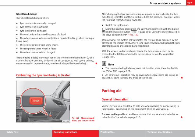
217Driver assistance systems
Wheel tread change
The wheel tread changes when:
● Tyre pressure is manually changed
● Tyre pressure is insufficient
● Tyre structure is damaged
● The vehicle is unbalanced because of a load
● The wheels on an axle are subject to a heavier load (e.g. when towing aheavy load)
● The vehicle is fitted with snow chains
● The temporary spare wheel is fitted
● The wheel on one axle is changed
There may be a delay in the reaction of the tyre monitoring indicator or itmay not indicate anything under certain circumstances (e.g. sporty driving,snow-covered or unpaved roads, or when driving with snow chains).
Calibrating the tyre monitoring indicator
Fig. 147 Glove compart-ment: tyre control switch
After changing the tyre pressure or replacing one or more wheels, the tyremonitoring indicator must be recalibrated. Do the same, for example, whenthe front and rear wheels are swapped.
● Switch the ignition on.
● Store the new tyre pressure in the Easy Connect system with the button and the function button Setup ⇒ page 80 or using the switch located in
the glove compartment* ⇒ Fig. 147.
When driving, the system self-calibrates the tyre pressure provided by thedriver and the wheels fitted. After a long journey with varied speeds the pro-grammed values are collected and monitored.
With the wheels under very heavy loads, the tyre pressure must be in-creased to the total recommended tyre pressure before the calibration⇒ page 307.
Note● The tyre monitoring indicator does not function when there is a fault inthe ESC or ABS ⇒ page 222.
● An erroneous indication may be given when snow chains are in use be-cause the chains increase the tread of the wheel.
Parking aid
General information
Various systems are available to help you when parking or manoeuvring intight spaces, depending on the equipment fitted on your vehicle.
The rear parking aid is an audible assistant that warns about obstacles lo-cated behind the vehicle ⇒ page 218.
Safety First Operating instructions Practical Tips Technical specifications

218 Driver assistance systems
During parking, the parking system plus assists you visually and audiblyabout obstacles detected in front and behind the vehicle ⇒ page 219.
WARNING
● Always pay attention (also when looking straight ahead) to traffic andthe vehicle surroundings. The assistance systems are not a replacementfor driver awareness. When inserting or removing the vehicle from a park-ing space, or when performing similar manoeuvres the driver always as-sumes the responsibility.
● Take into account that the system is not always in conditions to rec-ognise or represent certain surfaces, such as dress fabric: Risk of causingan accident!
● The sensors and cameras have blind spots, making the detection ofpeople and objects impossible. Pay special attention to children and ani-mals: Risk of causing an accident!
● Always keep visual control of the vehicle surroundings: use the rearvision mirrors for additional help.
CAUTION● Under certain circumstances, the system does not detect or display cer-tain objects:
– Objects such as snow chains, trailer draw bars, bars or fences
– Objects that are located above the sensors, such as protrusions in awall.
– Objects with certain surfaces or structures, such as wire mesh fencesor powder snow.
● When the vehicle approaches a low obstacle, it could disappear fromthe angle of measurement. In this case, take into account that the systemwill no longer warn about this obstacle.
● The knocks or damage on the radiator grille, bumper, wheel arch and ve-hicle underbody can adjust the orientation of the sensors. This can affectthe parking aid function. Have the function checked by a specialised work-shop.
Note● In certain situations, the system can give a warning even though there isno obstacle in the detected area, e.g:
– for roads with certain surfaces, or with long grass
– for external ultrasound sources, such as cleaning vehicles
– In downpours, intense snow or dense exhaust gases
● In order to familiarise yourself with the system, it is advised that youpractice parking in an area or car park that is free from traffic. There must begood weather and light conditions.
● The volume and tone of the warnings can be modified, in addition to theindications ⇒ page 221.
● In vehicles without a driver information system, these parameters can bemodified in a SEAT Official Service or in a specialised workshop.
● Please observe information on towing a trailer ⇒ page 221.
● The display on the Easy Connect screen shows a slight time delay.
● To ensure that the parking aid works properly, the sensors must be keptclean and free of ice and snow.
Rear parking aid*
The rear parking aid is an audible assistant.
Description
There are sensors integrated in the rear bumper. When the sensors detectan obstacle, you are alerted by audible warnings.
Make sure that the sensors are not covered by adhesives, residues and thelike, given that this could affect the system operation. Cleaning instructions⇒ page 239.
The approximate measurement range of the sensors is:

219Driver assistance systems
rearside 0.90 m
centre 1.60 m
As you approach the obstacle, the time interval between the audible warn-ings will be reduced. When you reach around 0.30 m the warning will beconstant: Do not continue to move forward (or backward) ⇒ in Generalinformation on page 218, ⇒ in General information on page 218 !
If you maintain separation from the obstacle, the volume of the warning be-gins to reduce after four seconds (does not affect the tone of the constantwarning).
Activate
When engaging reverse gear, the parking aid is automatically switched on.This is confirmed with a short warning.
Parking system plus*
Parking system plus assists you audibly and visually whenparking.
Fig. 148 Representedarea
There are sensors integrated in the front and rear bumpers. When the sen-sors detect an obstacle, audible and visual warnings are given.
Make sure that the sensors are not covered by adhesives, residues and thelike, given that this could affect the system operation. Cleaning instructions⇒ page 239.
The approximate measurement range of the sensors is:
1.20 m
0.90 m
1.60 m
0.90 m
As you approach the obstacle, the time interval between the audible warn-ings will be reduced.
If you maintain separation from the obstacle, the volume of the warning be-gins to reduce after four seconds (does not affect the tone of the constantwarning).
Activating/Deactivating
Fig. 149 Centre console:parking aid button
A
B
C
D
Safety First Operating instructions Practical Tips Technical specifications

220 Driver assistance systems
Switching on
– Engage reverse gear or
– Press the button on the centre console ⇒ Fig. 149. A shortconfirmation signal will be heard and the button symbol willlight up yellow.
With certain equipment (Adaptive Cruise Control), the system willbe switched on automatically when the vehicle reverses a givendistance (approx. 10 cm if an obstacle is detected at the rear andapprox. 20 cm if no obstacle is detected at the rear).
Switching off
– Drive forwards at more than 10 km/h (6 mph), or
– Press the button, or
– Switch the ignition off
Segments of the visual indication
The distance of separation from the obstacle can be estimated using thesegments around the vehicle. With certain equipment (Radio Standard), theyellow lines* mark the estimated path, depending on the angle of theturned steering wheel. A white segment is seen when an obstacle is detec-ted out of the path of the vehicle. The red segments represent obstacles de-tected within the path. As the vehicle approaches an obstacle, the seg-ments are displayed closer to the vehicle. When the penultimate segment isdisplayed, this means that the vehicle has reached the collision zone. In thecollision zone, obstacles are represented in red, including those out of thepath. Do not continue to move forward (or backward) ⇒ in General infor-mation on page 218, ⇒ in General information on page 218 !
Automatic activation1)
When the parking aid (ParkPilot) is automatically switched on this is shownin miniature on the left side of the display.
When slowly approaching an obstacle located in front of the vehicle, the au-tomatic activation only functions each time the speed is reduced below ap-proximately 10 km/h (6 mph) for the first time. If the parking aid is deactiva-ted using the button, the following actions must be carried out in orderfor it to automatically reactivate:
● Switch off the ignition and switch it on again.
● OR: Accelerate above 10 km/h (6 mph) before reducing speed belowthis number again.
● OR: Place the selector lever in position P and then move it from this po-sition.
● OR: Switch on and off the automatic activation in the Easy Connect sys-tem menu.
The automatic activation with parking aid miniature indication can beswitched on and off from the Easy Connect system menu ⇒ page 81:
● Switch the ignition on.
● Press button .
● Press the Setup function button.
● Press the Parking and Manoeuvring function button.
● Select the parking aid (ParkPilot) from the list.
● Automatic activation.
When the function button check box is activated , the function is on.
1) Available only with certain equipment.

221Driver assistance systems
Adjusting the display and audible warnings
The settings for the display and audible warnings are con-trolled via the Easy Connect*.
Requirements: the parking aid must be switched on.
– Select: button CAR > control button Car* Systems > Driver assis-tant > Parking aid ⇒ page 81.
Automatic activation1)
on – activates the Automatic activation option ⇒ page 220
off – deactivates the Automatic activation option ⇒ page 220.
Front volume
Volume in the front and rear area.
Front sound settings
Frequency (tone) of the sound in the front area.
Rear volume
Volume in the rear area
Rear sound settings
Frequency (tone) of the sound in the rear area.
Adjust volume
With the parking aid switched on, the active audio/video source volume willbe reduced to the intensity of the selected setting.
You will hear a short test tone from the corresponding speaker each timeyou make a new setting.
Error messages
When the parking aid is activated or when switching it on, if a continuouswarning can be heard over several seconds (additionally, in the case ofParking system plus the LED of the button flashes), there is a fault in thesystem. If the fault does not disappear before switching off the ignition, thenext time the parking aid is switched on by engaging reverse gear the faultwill only be indicated with the flashing LED on the button.
Parking system plus*
If there is a fault in a sensor, the symbol is displayed on the Easy Con-nect display in front of/behind the vehicle. If a rear sensor is faulty, only theobstacles in the areas A and B are displayed ⇒ Fig. 148. If a front sensoris faulty, only the obstacles in the areas C and D are displayed.
Have the fault corrected by a specialised workshop without delay.
Towing bracket
If the trailer power socket is occupied, the rear parking aid sensors will notactivate when reverse gear is engaged, or when the button is pressed.This function may not be covered under warranty if the towing bracket is notfactory-fitted. This causes the following limitations:
Parking system plus*
There will be no warning about the presence of obstacles in the rear area.The monitoring in the front area remains active. The optical display changesto towing mode.
1) available only with certain equipment - Radio Standard
Safety First Operating instructions Practical Tips Technical specifications

222 Intelligent technology
Practical Tips
Intelligent technology
Electronic Stability Control (ESC)
Description
The ESC helps to improve safety. It reduces the tendency to skid and im-proves the stability and roadholding of the vehicle. The ESC detects criticalhandling situations, such as vehicle understeer or oversteer, or wheelspinon the driving wheels. It stabilises the vehicle by braking individual wheelsor by reducing the engine torque. The warning lamp will flash on the instru-ment panel when the ESC is intervening .
ESC includes the Anti-lock brake system (ABS), the brake assist system, thetraction control system (ASR), electronic differential lock (EDL), electronicself-locking*, selective torque control* and tractor-trailer sway mitigation*.ESC also helps stabilise the vehicle by changing the torque.
Anti-lock brake system (ABS)
ABS prevents the wheels from locking up under braking until the vehiclehas reached a virtual standstill. You can continue to steer the vehicle evenwhen the brakes are on full. Keep your foot on the brake pedal and do notpump the brakes. You will feel the brake pedal pulsate while the ABS isworking.
Brake assist system
The brake assist system can reduce the required braking distance. The brak-ing force is automatically boosted if you press the brake pedal quickly in anemergency. You must keep pressing the brake pedal until the danger haspassed.
Traction control system (ASR)
In the event of wheelspin, the traction control system reduces the enginetorque to match the amount of grip available. This helps the car to startmoving, accelerate or climb a gradient.
Electronic differential lock (EDL)
When the EDL detects wheelspin, it brakes the spinning wheel and directsthe power to the other driven wheel. This function is available up to a speedof around 100 km/h, 62 mph).
To prevent the disc brake of the braked wheel from overheating, the EDLcuts out automatically if subjected to excessive loads. The vehicle can stillbe driven. The EDL will switch on again automatically when the brake hascooled down.
Tractor-trailer sway mitigation*
If the vehicle is pulling a trailer, it will control the following: Tractor-trailerstend to sway. When the swaying of the trailer is felt by the vehicle and de-tected by the ESC, it will automatically brake the towing vehicle within thelimits of the system and mitigate the sway. Tractor-trailer sway mitigation isnot available in all countries.
Electronic self-locking*/Selective torque control*
When driving around bends, an electronic self-locking intervenes. The frontwheel on the inside of the curve, or the two inside wheels, respectively, areselectively braked as required. This minimises the traction of the frontwheels, allowing you to take bends with greater precision and neutrality. Incertain circumstances, where roads are wet or snow-covered, the respectivesystem may not intervene.
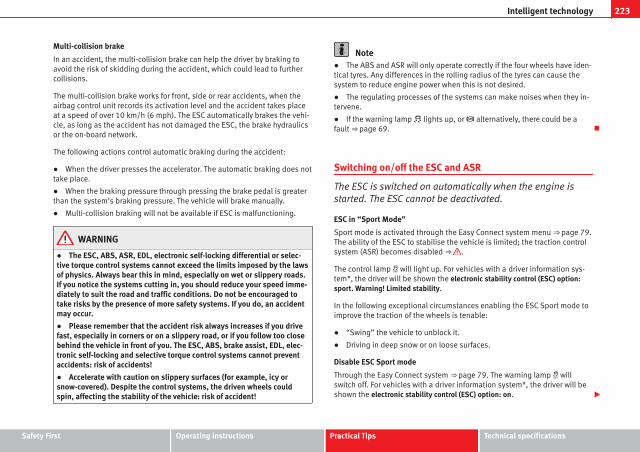
223Intelligent technology
Multi-collision brake
In an accident, the multi-collision brake can help the driver by braking toavoid the risk of skidding during the accident, which could lead to furthercollisions.
The multi-collision brake works for front, side or rear accidents, when theairbag control unit records its activation level and the accident takes placeat a speed of over 10 km/h (6 mph). The ESC automatically brakes the vehi-cle, as long as the accident has not damaged the ESC, the brake hydraulicsor the on-board network.
The following actions control automatic braking during the accident:
● When the driver presses the accelerator. The automatic braking does nottake place.
● When the braking pressure through pressing the brake pedal is greaterthan the system’s braking pressure. The vehicle will brake manually.
● Multi-collision braking will not be available if ESC is malfunctioning.
WARNING
● The ESC, ABS, ASR, EDL, electronic self-locking differential or selec-tive torque control systems cannot exceed the limits imposed by the lawsof physics. Always bear this in mind, especially on wet or slippery roads.If you notice the systems cutting in, you should reduce your speed imme-diately to suit the road and traffic conditions. Do not be encouraged totake risks by the presence of more safety systems. If you do, an accidentmay occur.
● Please remember that the accident risk always increases if you drivefast, especially in corners or on a slippery road, or if you follow too closebehind the vehicle in front of you. The ESC, ABS, brake assist, EDL, elec-tronic self-locking and selective torque control systems cannot preventaccidents: risk of accidents!
● Accelerate with caution on slippery surfaces (for example, icy orsnow-covered). Despite the control systems, the driven wheels couldspin, affecting the stability of the vehicle: risk of accident!
Note● The ABS and ASR will only operate correctly if the four wheels have iden-tical tyres. Any differences in the rolling radius of the tyres can cause thesystem to reduce engine power when this is not desired.
● The regulating processes of the systems can make noises when they in-tervene.
● If the warning lamp lights up, or alternatively, there could be afault ⇒ page 69.
Switching on/off the ESC and ASR
The ESC is switched on automatically when the engine isstarted. The ESC cannot be deactivated.
ESC in “Sport Mode”
Sport mode is activated through the Easy Connect system menu ⇒ page 79.The ability of the ESC to stabilise the vehicle is limited; the traction controlsystem (ASR) becomes disabled ⇒ .
The control lamp will light up. For vehicles with a driver information sys-tem*, the driver will be shown the electronic stability control (ESC) option:sport. Warning! Limited stability.
In the following exceptional circumstances enabling the ESC Sport mode toimprove the traction of the wheels is tenable:
● “Swing” the vehicle to unblock it.
● Driving in deep snow or on loose surfaces.
Disable ESC Sport mode
Through the Easy Connect system ⇒ page 79. The warning lamp willswitch off. For vehicles with a driver information system*, the driver will beshown the electronic stability control (ESC) option: on.
Safety First Operating instructions Practical Tips Technical specifications

224 Intelligent technology
Disable ASR
ASR mode is deactivated ⇒ page 79 through the Easy Connect systemmenu. The traction control system will be disabled.
The control lamp will light up. For vehicles with a driver information sys-tem* the driver will be informed that ASR is disabled.
In the following exceptional circumstances enabling the ESC Sport mode toimprove the traction of the wheels is tenable:
● “Swing” the vehicle to unblock it.
● Driving in deep snow or on loose surfaces.
Activate ASR
ASR mode is activated ⇒ page 79 through the Easy Connect system menu.The traction control system will be enabled.
The control lamp switches off. For vehicles with a driver information sys-tem* the driver will be informed that ASR is enabled.
WARNING
You should switch on the ESC Sport mode only if the traffic conditionsand your driving ability allow you to do so safely: risk of skidding!
● With ESC in Sport mode, the stabilising function will be limited to al-low for a sportier drive. The driving wheels could spin and the vehiclecould skid.
NoteIf the ASR is disconnected or the ESC’s Sport mode is selected, cruise con-trol* will be switched off.
Brakes
New brake pads
For the first 400 km (250 miles), new brake pads have not yet reached theirmaximum braking capacity, and need to be “run in” first. However, you cancompensate for the slightly reduced braking effect by applying more pres-sure on the brake pedal. Avoid overloading the brakes while running themin.
Wear
The rate of wear on the brake pads depends a great deal on how you driveand the conditions in which the vehicle is operated. This is a particularproblem in urban traffic and short stretches, or with very sporty driving.
Depending on the speed, the braking force, and the environmental condi-tions (for example, the temperature, air humidity, etc.) noises may be pro-duced on braking.
Wet roads or road salt
In certain situations (for example, on driving through flooded areas, in se-vere downpours or after washing the vehicle) the braking action could bedelayed if the discs and pads are damp, or frozen in winter. In this case thebrakes should be dried by pressing the brake pedal several times.
At high speed and with the windscreen wipers activated, the brake pads willbriefly touch the brake discs. This takes place, although unnoticeable to thedriver, at regular intervals to improve the response time of the brakes whenthey are wet.
The effectiveness of the brakes can also be temporarily reduced if the vehi-cle is driven for some distance without using the brakes when there is a lotof salt on the road in winter. The layer of salt that accumulates on the discsand pads can be removed by gently applying the brakes a few times.

225Intelligent technology
Corrosion
There may be a tendency for corrosion to form on the discs and dirt to buildup on the brake pads if the vehicle is used infrequently or the brakes arenot used very often.
If the brakes are not used frequently, or if rust has formed on the disks, it isadvisable to clean off the pads and disks by braking firmly a few times at amoderately high speed ⇒ .
Fault in the brake system
If the brake pedal travel should ever increase suddenly, this may mean thatone of the two brake circuits has failed. Drive immediately to the nearestspecialised workshop and have the fault repaired. Drive there slowly and re-member that you will have to apply more pressure on the brake pedal andallow for longer stopping distances.
Low brake fluid level
Malfunctions can occur in the brake system if the brake fluid level is toolow. The brake fluid level is monitored electronically.
Brake servo
The brake servo increases the pressure you apply to the brake pedal. Itworks only when the engine is running.
WARNING
● Apply the brakes heavily to clean the brake system only in a suitabletraffic situation. Do not put other road users in danger: risk of causing anaccident.
● Ensure the vehicle does not move while in neutral, when the engine isstopped. Failure to do so could result in an accident.
CAUTION● Never let the brakes “drag” by leaving your foot on the pedal when it isnot necessary to brake. This overheats the brakes, resulting in longer stop-ping distances and greater wear.
● Before driving down a long, steep gradient, it is advisable to reducespeed and select a lower gear. This makes use of engine braking and re-lieves the brakes. If you still have to use the brakes, it is better to brakefirmly at intervals than to apply the brakes continuously.
Note● If the brake servo is out of action due to a malfunction, or if the car hasto be towed, you will have to press the brake pedal considerably harder tomake up for the lack of servo assistance.
● If you wish to equip the vehicle with accessories such as a front spoileror wheel covers, it is important that the flow of air to the front wheels is notobstructed, otherwise the brakes can overheat.
Electro-mechanical steering
Electro-mechanical power steering assists the driver whensteering.
Electro-mechanical power steering adapts electronically to the speed of thecar, torque and turning angle.
If the power steering should fail at any time or the engine is switched off (forinstance when being towed), the car can still be steered. However, more ef-fort than normal will be required to turn the steering wheel.
Driver warning lamps and messages
(in red) Faulty steering! To park the vehicle
Safety First Operating instructions Practical Tips Technical specifications

226 Intelligent technology
If the warning lamp remains on and the driver indication appears, the powersteering could be faulty.
Do not continue driving. Seek specialist assistance.
(in yellow) Steering: System fault! You may continue driving.
If the warning lamp comes on, the steering could react with more difficultlyor more sensitivity than normal. In addition, when driving in a straight linethe steering wheel may be off-centre.
Drive slowly to a specialised workshop and have the fault repaired.
(in yellow) Steering lock: fault! Go to an Official Service
The electronic steering lock is malfunctioning.
Go to a specialised workshop as soon as possible and have the fault re-paired.
WARNING
Take it immediately to a specialised workshop and have the fault re-paired: risk of accident!
NoteIf a red or yellow warning lamp come on briefly, you can continue driv-ing.
Progressive steering
Depending on the vehicle's equipment, the progressive steering can adaptsteering hardness to the driving conditions. Progressive steering only workswhen the engine is running.
In city traffic there is no need to turn the wheel so much when parking, ma-noeuvring or in tight turns.
On the road or on motorways, the progressive steering transmits, e.g., onbends, a sportier, more direct and perceptibly more dynamic sensation tothe steering wheel
Power Management
This system helps to ensure reliable starting
The power management controls the distribution of electri-cal energy and thus helps to ensure that there is alwaysenough power available to start the engine.
If a vehicle with a conventional electrical system is left parked for a longtime, the battery will gradually lose its charge because certain electricalequipment (such as the electronic gearbox lock) continues to draw currenteven when the ignition is off. In some cases there may not be enough poweravailable to start the engine.
Your vehicle is equipped with an intelligent power management system tocontrol the distribution of electrical energy. This significantly improves relia-bility when starting the engine, and also prolongs the useful life of the bat-tery.
The main functions incorporated in the power management system are bat-tery diagnosis, residual current management and dynamic power manage-ment.

227Intelligent technology
Battery diagnosis
The battery diagnosis function constantly registers the condition of the bat-tery. Sensors detect the battery voltage, battery current and battery temper-ature. This enables the system to calculate the current power level andcharge condition of the battery.
Residual current management
The residual current management reduces power consumption while the ve-hicle is parked. It controls the supply of power to the various electrical com-ponents while the ignition is switched off. The system takes the battery di-agnosis data into consideration.
Depending on the power level of the battery, the individual electrical com-ponents are switched off one after the other to prevent the battery from los-ing too much charge and to ensure that the engine can be started reliably.
Dynamic power management
While the vehicle is moving, this function distributes the available power tothe various electrical components and systems according to their require-ments. The power management ensures that on-board systems do not con-sume more electrical power than the alternator can supply, and thus main-tains the maximum possible battery power level.
Note● The power management system is not able to overcome the given physi-cal limits. Please remember that the power and useful life of the battery arelimited.
● When there is a risk that the vehicle will not start, the alternator powerfailure or low battery charge level warning lamp will be shown ⇒ page 69.
Note carefully
Starting ability has first priority.
Short trips, city traffic and low temperatures all place a heavy load on thebattery. In these conditions a large amount of power is consumed, but onlya small amount is supplied. The situation is also critical if electrical equip-ment is in use when the engine is not running. In this case power is con-sumed when none is being generated.
In these situations you will be aware that the power management system isintervening to control the distribution of electrical power.
When the vehicle is parked for long periods
If you do not drive your vehicle for a period of several days or weeks, thepower management will gradually shut off the on-board systems one byone, or reduce the amount of current they are using. This limits the amountof power consumed and helps to ensure reliable starting even after a longperiod. Some convenience functions, such as remote vehicle opening, maynot be available under certain circumstances. These functions will be re-stored when you switch on the ignition and start the engine.
With the engine switched off
For example, if you listen to the sound system with the engine switched offthe battery will run down.
If the energy consumption means there is a risk that the engine will notstart, a text will appear in vehicles with a driver information system*.
This driver indicator tells you that you must start the engine so that the bat-tery can recharge.
When the engine is running
Although the alternator generates electrical power, the battery can still be-come discharged while the vehicle is being driven. This can occur when alot of power is being consumed but only a small amount supplied, especial-ly if the battery is not fully charged initially.
Safety First Operating instructions Practical Tips Technical specifications

228 Intelligent technology
To restore the necessary energy balance, the system will then temporarilyshut off the electrical components that are using a lot of power, or reducethe current they are consuming. Heating systems in particular use a largeamount of electrical power. If you notice, for instance, that the seat heating*or the heated rear window is not working, they may have been temporarilyswitched off or regulated to a lower heat output. These systems will beavailable again as soon as sufficient electrical power is available.
You may also notice that the engine runs at a slightly faster idling speed.This is quite normal, and no cause for concern. The increased idling speedallows the alternator to meet the greater power requirement and charge thebattery at the same time.
Information recorded in the control units
Your vehicle is fitted at the factory with a series of electronic control unitsresponsible for the engine and gearbox management. In addition, the con-trol units supervise the correct performance of the exhaust gas system andthe airbag systems.
Therefore, while the vehicle is being driven, these electronic control unitsare continuously analysing the vehicle data. In the event of faults or devia-tions from the theoretical values, only this data is stored. Generally, the in-strument panel warning lamps indicate whether there are any malfunctions.
This data can only be read and analysed using special equipment.
The storing of the data allows specialised workshops to detect and repairfaults. Stored data may include:
● Important data about the engine and gearbox
● Speed
● Direction of travel
● Braking force
● Seat belt check
The vehicle control units never record conversations held by passengers inthe vehicle.
If the control unit records an accident with airbag activation, the systemmay automatically send a signal. This will depend on the network operator.Normally, transmission is only possible in areas with sufficient coverage.
Event Data Recorder
The vehicle is not fitted with an event data recorder.
An event data recorder temporarily stores the vehicle information. There-fore, in the event of accident, it is possible to obtain detailed informationabout how the accident occurred. For example, in vehicles with airbag sys-tems, data relating to speed of impact, seat belt status, seat positions andairbag activation times may be stored. The volume of data depends on themanufacturer.
Event data recorders can only be mounted with authorisation from the vehi-cle owner and, in some countries, they are governed by local legislation.
Reprogramming control units
On the whole, all the data required for the component management is stor-ed in the control units. The programming of certain convenience functions,such as the turn signal convenience mode, individual door opening and dis-play indications can be modified using special equipment at the workshop.If the convenience functions are reprogrammed, the Instruction Manual in-formation and descriptions will not coincide with the modified functions.Therefore, SEAT recommends that any changes are recorded in the “Otherworkshop notes section” of the Service Plan.
You can find out about possible reprogramming at your SEAT Official Serv-ice.

229Intelligent technology
Event recorder
In the footwell on the driver side you will find the diagnostics connectionsocket for reading the event recorder. The event recorder stores operatingdata and data on the status of the electronic control units. The events re-corder should only be read and deleted by a SEAT Official Service or special-ised workshop.
WARNING
The diagnostics connection socket must not be used for private purpo-ses. Improper use can cause malfunctions: risk of accident!
Safety First Operating instructions Practical Tips Technical specifications

230 Driving and the environment
Driving and the environment
Running in the engine
A new vehicle should be run in over a distance of 1500 km (1000 miles). Forthe first 1000 km (600 miles) the engine speed should not exceed 2/3 ofthe maximum permissible engine speed. In doing so, do not accelerate atfull throttle and do not drive with a trailer! From 1000 to 1500 km (600 to1000 miles) you can gradually increase the engine rpm and road speed.
During its first few hours of running, the internal friction in the engine isgreater than later on when all the moving parts have bedded down.
How the vehicle is driven for the first 1500 km (1000 miles) influences thefuture engine performance. Subsequently, also drive at a moderate rate, es-pecially when the engine is still cold: this will lead to less engine wear andtear and will prolong its useful life.
You should also avoid driving with the engine speed too low. Change downto a lower gear when the engine no longer runs “smoothly”. If the enginerevs too much, cut fuel injection to protect the engine.
Driving through flooded roads
To prevent damage to the vehicle when driving through water, for example,along a flooded road, please observe the following:
● The water should never come above the lower edge of the bodywork.
● Drive at pedestrian speed.
WARNING
After driving through water, mud, sludge, etc., the braking effect can bedelayed slightly due to moisture build-up on the discs and brake pads.Applying the brakes carefully several times will remove the moisture andrestore the full braking effect.
CAUTION● Driving through flooded areas may severely damage vehicle compo-nents such as the engine, transmission, running gear or electrical system.
● Whenever driving through water, the Start-Stop system* must be switch-ed off ⇒ page 169.
Note● Check the depth of the water before entering the flooded zone.
● Do not stop in the water, drive in reverse, or stop the engine in any sit-uation.
● Note that vehicles travelling in the opposite direction may splash waterthat could exceed the maximum permitted water height for your vehicle.
● Avoid driving through salt water (corrosion).
Installation of exhaust gas filtration systems
Catalytic converter
Applies to vehicles with petrol engine: The vehicle must only be used withunleaded petrol, otherwise the catalytic converter will be irreparably dam-aged.

231Driving and the environment
Never drive until the tank is empty; an irregular supply of fuel can causefaulty combustion. In these cases, unburned fuel reaches the exhaust sys-tem, which can overheat and damage the catalytic converter.
Diesel particulate filter
Applies to vehicles with diesel engine: The diesel particulate filter can filterout almost all soot particles contained in the exhaust gas. In normal drivingconditions the filter is self-cleaning. The Diesel particulate filter is cleanedautomatically without need for indication by the warning lamp . This maybe noticed because the engine idle speed increases and an odour may bedetected.
If automatic filter purification cannot be carried out (because only shorttrips are taken, for example), soot will accumulate on the filter and the Die-sel particulate filter warning lamp will switch on.
Facilitate the automatic filter cleaning process by driving in the followingmanner: Drive for approximately 15 minutes at a minimum speed of 60 km/h (40 mph) in 4th or 5th gear (automatic gearbox: gear S). Maintain the en-gine speed at approx. 2000 rpm. The rise in temperature causes the soot onthe filter to burn. On completion of the cleaning the warning lamp willswitch off. If the warning lamp does not switch off, go immediately to a spe-cialised workshop to rectify the problem.
WARNING
● Because of the high temperatures which can occur in the exhaust gascontrol system (catalytic converter or diesel particulate filter), do notpark the vehicle where the exhaust can come into contact with flamma-ble materials under the car (e.g. on grass or at the forest edge). Fire haz-ard!
● Do not apply wax underneath the vehicle around the area of the ex-haust system: Fire hazard!
Economic and ecological driving
Fuel consumption, environmental pollution and wear to the engine, brakesand tyres depends largely on driving style. Fuel consumption can be re-duced by 10-15% with an economical driving style and proper anticipationof traffic conditions. The following section gives you some tips on lesseningthe impact on the environment and reducing your operating costs at thesame time.
Foresight when driving
Acceleration causes the vehicle to consume more fuel. If you think aheadwhen driving, you will need to brake less and thus accelerate less. Whereverpossible, let the car roll slowly to a stop, with a gear engaged (for instancewhen you can see that the next traffic lights are red). This takes advantageof the engine braking effect, reducing wear on the brakes and tyres. Emis-sions and fuel consumption will drop to zero due to the overrun fuel cut-off.
Changing gear to save energy
An effective way of saving is to change in advance to a higher gear. Runningthe engine at high rpm in the lower gears uses an unnecessary amount offuel.
Manual gearbox: shift up from first to second gear as soon as possible. Inany case, we recommend that you change to a higher gear upon reaching2000 rpm or so. Choosing the right gear enables fuel savings. Select thehighest possible gear appropriate for the driving situation (the engineshould continue functioning with cyclical regularity).
Automatic gearbox: accelerate gradually and without reaching the “kick-down” position.
Avoid driving at high speed
Avoid travelling at top speed, whenever possible. Fuel consumption, emis-sion of harmful gases and noise pollution multiply disproportionately asspeed is increased. Driving at moderate speeds will help to save fuel.
Safety First Operating instructions Practical Tips Technical specifications

232 Driving and the environment
Reduce idling time
In vehicles with the Start-Stop system idling is automatically reduced. In ve-hicles without the Start-Stop system it is worth switching off the engine, forexample, at level crossings and at traffic lights that remain red for long peri-ods of time. When an engine has reached operating temperature, and de-pending on the cylinder capacity, keeping it switched off for a minimum ofabout 5 seconds already saves more than the amount of fuel necessary forrestarting.
The engine takes a long time to warm up when it is idling. Mechanical wearand pollutant emissions are also especially high during this initial warm-upphase. It is therefore best to drive off immediately after starting the engine.Avoid running the engine at high speed.
Regular maintenance
Regular servicing helps in saving fuel even before the engine is started. Awell-serviced engine gives you the benefit of improved fuel efficiency aswell as maximum reliability and an enhanced resale value. A badly servicedengine can consume up to 10% more fuel than necessary.
Avoid short journeys
The engine and catalytic converter need to reach their optimal operatingtemperature in order to minimise fuel consumption and emissions.
A cold engine consumes a disproportionate amount of fuel. The engine onlyreaches its working temperature after about four kilometres (2.5 miles),when fuel consumption will return to a normal level.
Check tyre pressure
Always make sure the tyres are inflated to the correct pressures⇒ page 265 to save fuel. If the pressure is below half bar, fuel consumptionmay increase by 5%. Due to the greater rolling resistance, under-inflationalso increases tyre wear and impairs handling.
Do not use winter tyres all year round as they increase fuel consumption byup to 10%.
Avoid carrying unnecessary loads
Given that every kilo of extra weight will increase the fuel consumption, it isadvisable to always check the luggage compartment to make sure that nounnecessary loads are being transported.
Since the luggage rack increases the aerodynamic drag of the vehicle, youshould remove it when not needed. This will save, at a speed of 100-120km/h (60-75 mph), approximately 12% of fuel.
Save electrical energy
The engine drives the alternator, thereby generating electricity. This impliesthat any increase in power consumption also increases fuel consumption!For this reason, switch off any unneeded consumption of electricity. Electri-cal equipment which uses a lot of electricity includes the blower (at a highsetting), the rear window heating and the seat heating*.
Environmental friendliness
Environmental protection is a top priority in the design, choice of materialsand manufacture of your new SEAT.
Constructive measures to encourage recycling
● Joints and connections designed for easy dismantling
● Modular construction to facilitate dismantling
● Increased use of single-grade materials.
● Plastic parts and elastomers are marked in accordance with ISO 1043,ISO 11469 and ISO 1629.
Choice of materials
● Use of recycled materials.
● Use of compatible plastics in the same part if its components are noteasily separated.

233Driving and the environment
● Use of recycled materials and/or materials originating from renewablesources.
● Reduction of volatile components, including odour, in plastic materials.
● Use of CFC-free coolants.
Ban on heavy metals, with the exceptions dictated by law (Annex II of ELVDirective 2000/53/EC): cadmium, lead, mercury, hexavalent chromium.
Manufacturing methods
● Reduction of the quantity of thinner in the protective wax for cavities.
● Use of plastic film as protection during vehicle transport.
● Use of solvent-free adhesives.
● Use of CFC-free coolants in cooling systems.
● Recycling and energy recovery from residues (RDF).
● Improvement in the quality of waste water.
● Use of systems for the recovery of residual heat (thermal recovery, en-thalpy wheels, etc.).
● The use of water-soluble paints
Safety First Operating instructions Practical Tips Technical specifications

234 Trailer
Trailer
Trailer towing
What do you need to bear in mind when towing a trailer?
Your vehicle may be used to tow a trailer when fitted with the correct equip-ment.
If you wish to retrofit a towing bracket, consult ⇒ page 236.
Connectors
Your vehicle is fitted with a 12-pin connector for the electrical connectionbetween the trailer and the vehicle.
If the trailer has a 7-pin plug you will need to use an adapter cable. This isavailable in any Technical Service.
Trailer weight/drawbar load
Never exceed the authorised trailer weight. If you do not load the trailer upto the maximum permitted trailer weight, you can then climb correspond-ingly steeper slopes.
The maximum trailer weights listed are only applicable for altitudes up to1000 m above sea level. With increasing altitude the engine power andtherefore the vehicle climbing ability are impaired because of the reducedair density. The maximum trailer weight has to be reduced accordingly. Theweight of the vehicle and trailer combination must be reduced by 10% forevery further 1000 m (or part thereof). The gross combination weight is theactual weight of the laden vehicle plus the actual weight of the laden trailer.When possible, operate the trailer with the maximum permitted drawbarload on the ball joint of the towing bracket, but do not exceed the specifiedlimit.
The figures for trailer weights and drawbar loads that are given on the dataplate of the towing bracket are for certification purposes only. The correctfigures for your specific model, which may be lower than these figures forthe towing bracket, are given in the vehicle documentation or in ⇒ chap-ter Technical Data.
Distributing the load
Distribute loads in the trailer so that heavy objects are as near to the axle aspossible. Loads carried in the trailer must be secured to prevent them mov-ing.
Tyre pressure
Set tyre pressure to the maximum permissible pressure shown on the stick-er on the inside of the fuel tank flap. Set the tyre pressure of the trailer tyresin accordance with the trailer manufacturer's recommendations.
Exterior mirrors
Check whether you can see enough of the road behind the trailer with thestandard rear vision mirrors. If this is not the case, you should have addi-tional exterior mirrors fitted. Both exterior mirrors should be mounted onhinged extension brackets. Adjust the mirrors to give sufficient vision to therear.
WARNING
Never transport people in a trailer. This could result in fatal accidents.

235Trailer
Note● Towing a trailer places additional demands on the vehicle. We recom-mend additional services between the normal inspection intervals if the ve-hicle is used frequently for towing a trailer.
● Find out whether special regulations apply to towing a trailer in yourcountry.
Ball coupling of towing bracket*
The ball coupling is provided with instructions on fitting and removing theball coupling of the towing bracket.
WARNING
The towing bracket ball coupling must be stored securely in the luggagecompartment to prevent them being flung through the vehicle and caus-ing injury.
Note● By law, the ball coupling must be removed if a trailer is not being towedif it obscures the number plate.
Driving tips
Driving with a trailer always requires extra care.
Weight distribution
The weight distribution of a loaded trailer with an unladen vehicle is veryunfavourable. However, if this cannot be avoided, drive extra slowly to allowfor the unbalanced weight distribution.
Speed
The stability of the vehicle and trailer is reduced with increasing speed. Forthis reason, it is advisable not to drive at the maximum permissible speedin an unfavourable road, weather or wind conditions. This applies especiallywhen driving downhill.
You should always reduce speed immediately if the trailer shows the slight-est sign of snaking. Never try to stop the “snaking” by increasing speed.
Always brake in due course. If the trailer has an overrun brake, apply thebrakes gently at first and then, firmly. This will prevent the jerking that canbe caused by locking of trailer wheels. Select a low gear in due course be-fore going down a steep downhill. This enables you to use the engine brak-ing to slow down the vehicle.
Reheating
At very high temperatures and during prolonged slopes, driving in a lowgear and high engine speed, always monitor the coolant temperature gauge⇒ page 69.
Electronic Stability Control*
The ESC* system helps to stabilise the trailer in case of skidding or rocking.
Safety First Operating instructions Practical Tips Technical specifications

236 Trailer
Retrofitting a towing bracket*
It is possible to fit a towing bracket to the rear of the vehicle.
Fig. 150 Attachment points for towing bracket
If a towing bracket is to be fitted after the vehicle is purchased, this must becompleted according to the instructions of the towing bracket manufacturer.
The attachment points for the towing bracket A are on the lower part of thevehicle.
The distance between the centre of the ball coupling and the ground shouldnever be lower than the indicated value, even with a fully loaded vehicleand including the maximum drawbar load.
Elevation values for securing the towing bracket:
B 65 mm (minimum)
C 350 mm to 420 mm (fully laden vehicle)
D 1040 mm
E 317 mm
FLEON / LEON SC LEON ST
319 mm 596 mm
Fitting a towing bracket
● Driving with a trailer involves an extra effort for the vehicle. Therefore,before fitting a towing bracket, please contact a Technical Service to checkwhether your cooling system needs modification.
● The legal requirements in your country must be observed (e.g. the fittingof a separate control lamp).
● Certain vehicle components, e.g. the rear bumper, must be removed andreinstalled. The towing bracket securing bolts must be tightened using atorque wrench, and a power socket must be connected to the vehicle electri-cal system. This requires specialised knowledge and tools.
● Figures in the illustration show the elevation value and the attachmentpoints which must be considered if you are retrofitting a towing bracket.
WARNING
The towing brackets should be fitted at a specialised workshop.
● If the towing bracket is incorrectly installed, there is a serious dangerof accident.
● For your own safety, please observe the instructions provided by themanufacturer of the towing bracket.
CAUTION● If the power socket is incorrectly installed, this could cause damage tothe vehicle electrical system.

237Trailer
Note● SEAT recommends that the towing hooks be fitted at a specialised work-shop. Consult your SEAT dealer in case additional modifications to your ve-hicle are necessary.
● Due to the specific design of the exhaust, the fitting of a conventionaltowing hook is not recommended for some sportier versions. Please consultyour Technical Service.
Safety First Operating instructions Practical Tips Technical specifications

238 Care and cleaning
Care and cleaning
General information
Regular care helps to maintain the value of the vehicle.
Regular and careful care helps to maintain the value of the vehicle. This mayalso be one of the requirements for upholding any warranty claims in theevent of corrosion or paint defects.
SEAT Official Services and specialist retailers carry stocks of suitable carcare materials. Please follow the instructions for use on the packaging.
WARNING
● Cleaning products and other materials used for car care can be dam-aging to your health if misused.
● Always keep care products in a safe place, out of the reach of chil-dren. Failure to comply could result in poisoning.
For the sake of the environment● If possible, use environmentally friendly products.
● The remains of car care products should not be disposed of with ordina-ry household waste.
Care of vehicle exterior
Washing the vehicle
The longer substances such as insects, bird droppings, resinous tree sap,road dirt, industrial deposits, tar, soot or road salt and other aggressive ma-terials remain on the vehicle, the more damage they do to the paintwork.High temperatures (for instance due to strong sunlight) further intensify thecorrosive effect.
After the period when salt is put on the roads it is important to have the un-derside of the vehicle washed thoroughly.
Automatic car washes
Before going through a car wash, be sure to take the usual precautions suchas closing the windows and roof. If the vehicle has special accessories suchas spoilers or a roof carrier or two-way radio aerial, etc., it is advisable toconsult the car wash operator.
It is best to use a car wash without revolving bristles if possible.
Washing the vehicle with a high pressure cleaner
When washing the vehicle with a high-pressure cleaner, always follow theoperating instructions for the equipment. This applies particularly to the op-erating pressure and the spraying distance. Do not hold the nozzle tooclose to soft materials such as rubber hoses or seals. The same applies tothe parking aid sensors*, which are located in the rear bumper.
Do not use a nozzle that sprays the water out in a direct stream or one thathas a rotating jet for forcing off dirt.

239Care and cleaning
Washing the car by hand
When washing the car by hand, use plenty of water to soften the dirt first,and rinse off as well as possible.
Then clean the vehicle with a soft sponge, glove or brush using only slightpressure. You should start on the roof and work down. Special car shampooshould only be used for very persistent dirt.
Rinse the sponge or glove thoroughly and often.
Wheels, sills and similar should be cleaned last. Use a second sponge forthis.
WARNING
● The vehicle should only be washed with the ignition switched off.Failure to do so could result in an accident.
● Do not clean the underside of chassis, the inside of wheel arches orwheel trims without protecting your hands and arms. You may cut your-self on sharp-edged metal parts. Otherwise, there is a risk of sustainingcuts.
● When washing the car during the winter season: water and ice in thebrake system can reduce braking effectiveness: risk of accident!
CAUTION● Do not wash the vehicle in direct sunlight – otherwise the paint can bedamaged.
● Do not use sponges, abrasive household sponges or similar to clean in-sect remains. This could damage the surface.
● Clean off stubborn dirt (insects, etc.) from the headlights at regular in-tervals, for instance when filling the fuel tank. The headlights should onlybe washed with water, do not wipe them with a dry cloth or sponge. It isbest to use soapy water.
● Never wash tyres with a jet that sprays the water out in a direct stream.This could damage the tyres even if the spray is kept at a distance and onlyused for a very short time.
● Before washing the vehicle in an automatic car wash, please make sureto retract the exterior mirrors to prevent them from being damaged. Electri-cally retractable exterior mirrors must not be folded in or out by hand. Al-ways use the electrical power control.
CAUTION● If you wash the vehicle in an automatic car wash, proceed as follows tolock and prevent the windscreen wiper blades from being pushed up to-wards the top of the windscreen:
– the bonnet must be closed
– switch the ignition on and off
– press the windscreen wiper lever downwards briefly towards the front(windscreen wiper function). The windscreen wiper blades will belocked.
For the sake of the environmentThe car should only be washed in special wash bays. This prevents oily wa-ter from getting into the public drains. In some places, washing vehiclesanywhere else may be prohibited.
Sensors and camera lenses
● Use a small brush to remove snow and a de-icer spray to remove ice.
● Clean the sensors with a solvent-free product and a soft, dry cloth.
● Moisten the camera lens using a standard alcohol-based glass cleaningagent and clean the lens with a dry cloth. The area in front of the activeLane Assist* lens area is normally cleaned with the windscreen washer.
Safety First Operating instructions Practical Tips Technical specifications
240 Care and cleaning
CAUTION● When you clean the vehicle with a pressure washer,
– stay a suitable distance from the sensors on the front and rear bump-ers.
– Do not clean the camera lenses or surrounding area with the pressurewasher.
● Never use warm or hot water to remove snow and ice from the reversecamera lens, as it could crack the lens.
● Never use abrasive cleaning agents on the lens.
Care and polishing
Care
Waxing protects the paintwork. It is time to apply a good coat of wax whenwater no longer forms droplets and rolls off the clean paintwork.
Even if a wax solution is used regularly in the vehicle washing tunnel, it isadvisable to protect the paint with a hard wax coating at least twice a year.
In the summer, you will find it is much easier to remove dead insects (whichaccumulate on the bumper and the front of the bonnet) if the car has beentreated with care products recently.
Polishing
Polishing is only necessary if the paint has lost its shine, and the gloss can-not be brought back by putting on wax.
If the polish does not contain wax, a wax product should be applied afterpolishing.
CAUTION● Do not use polishes and hard wax on painted parts with a matt finish oron plastic parts.
● Do not apply paint polishes to the side trim that runs around the panor-amic roof and ends on the windscreen. However, it can be treated with hardwax.
Trims
In respect for the environment, the silver-plated trims on the body are madeof pure aluminium (they do not contain chrome).
Dirt or marks on the trim mouldings should be removed with a cleaningproduct with a neutral PH (do not use a chrome cleaner). Body polish is alsounsuitable for use on trim mouldings. The intensive cleaning fluids oftenused before the car goes into a car wash may contain alkaline substances,which can cause dull or milky patches when they dry out.
SEAT Official Services carry stocks of cleaning products which have beentested for use on your vehicle and are not harmful to the environment.
Plastic parts
Plastic parts are cleaned with a power washer. If this is not sufficient, plas-tic parts should only be treated with a special solvent-free plastic cleaningagent. Do not use paintwork cleaners, polishes or wax on plastic parts.

241Care and cleaning
Carbon components
The carbon parts on your vehicle have a painted surface. They do not needany special care and are cleaned just like any other painted part⇒ page 238.
Paint damage
Minor damage to the paint, such as scratches or stone chips, should betouched up without delay before the metal starts to corrode. Suitable touch-up brushes or sprays for your car can be obtained from a SEAT Official Serv-ice.
The number of the original paint finish on the vehicle is given on the datasticker ⇒ page 305.
If corrosion is already visible it must be thoroughly removed by a special-ised workshop.
Windows
Clear vision is an essential safety factor.
The windscreen must not be cleaned with insect remover or wax, otherwisethe windscreen wipers will not function properly (juddering).
Traces of rubber, oil, grease or silicone can be removed with a windowcleaning solution or a silicone remover. Wax residue can only be removedwith a special cleaner. Your SEAT Official Service will be able to provide youwith more detailed information.
The windows should also be cleaned on the inside at regular intervals.
Use a separate cloth or chamois to dry the windows. Cloths used for waxingand polishing contain residues that will cause smears on the glass.
WARNING
Do not use water-repellent coatings on the windscreen. In bad visibilityconditions (e.g. in the rain, dark or with a low sun), these coatings maycause dazzle: risk of accident! Such coatings can also cause the wind-screen wiper blades to make noise.
CAUTION● Remove snow and ice from windows and exterior mirrors with a plasticscraper only. To avoid scratches caused by dirt on the glass, the scrapershould only be pushed in one direction and not moved to and fro.
● The heating element for the rear window is located on the inner side ofthe window. To avoid damaging them, do not apply stickers to the heatingelements.
● Never use warm or hot water to remove snow and ice from windows andmirrors. This could cause the glass to crack!
Rims
The wheels require regular attention to preserve their appearance. It is im-portant to remove road salt and brake dust by washing the wheels at regu-lar intervals, otherwise the finish will be impaired.
After washing, the wheels should only be cleaned with an "acid-free" clean-ing agent for alloy wheels. This is available from SEAT Official Services andspecialist retailers. Never leave the cleaning agent on the rims for any lon-ger than specified in the instructions before rinsing it off. If the wheel clean-er fluid contains acid it can attack the surfaces of the wheel bolts.
Safety First Operating instructions Practical Tips Technical specifications

242 Care and cleaning
Car polish or other abrasive agents should not be used for maintaining therims. If the protective coating is damaged, e.g. by stone impact, the dam-aged area should be touched up immediately.
WARNING
Please note when cleaning the wheels that water, ice and road salt canimpair the effectiveness of the brakes; this can cause an accident.
Exhaust tail pipe
It is important to remove road salt and brake dust by washing the wheels atregular intervals, otherwise the exhaust tail pipe material could be dam-aged. To remove impurities, do not use rim, paint or chrome cleaners or oth-er abrasive products. Clean the exhaust tail pipes with cleaning productsthat are suitable for stainless steel.
SEAT Official Services carry stocks of cleaning products that have been tes-ted and approved for use on your vehicle.
Care of the vehicle interior
Radio display/Easy Connect* and control panel*
The display can be cleaned with a soft cloth and a professionally available“LCD cleaner”. Moisten the cloth with a small amount of the cleaning fluid.
The Easy Connect control panel* should first be cleaned with a brush sothat no dirt goes into the device or between the keys and housing. Next, werecommend cleaning the Easy Connect control panel* using a cloth damp-ened with water and washing-up liquid.
CAUTION● To avoid scratching the screen, do not wipe the display with a dry cloth.
● To avoid damage, ensure that no liquid goes into the Easy Connect con-trol panel*.
Plastic and leatherette parts
Plastic parts and leatherette can be cleaned with a damp cloth. If this is notsufficient, plastic parts and leatherette should only be treated with a specialsolvent-free plastic cleaner.
Textile covers and trim parts
Textile covers and trim parts (e.g. seats, door trim) should be cleaned regu-larly with a vacuum cleaner. This will remove surface dirt which could other-wise be rubbed into the textile material during use. Do not use steam clean-ers, as the steam could carry the dirt deeper into the textile material.
Normal cleaning
We recommend that you use a soft sponge or a commercially available lint-free, micro-fibre cloth for normal cleaning. Only use brushes on floor cover-ings and mats, as other textile surfaces could become damaged.
In the case of normal surface dirt you can use a foam cleaner. Use a spongeto spread the foam on the textile surface and to work it into the materiallightly. However, make sure that the textile material does not become soak-ing wet. Then dab off the foam with a dry and absorbent cloth (e.g. a micro-fibre cloth) and vacuum off any residue once the surface is completely dry.
Cleaning stains
Treat drink stains (such as coffee or fruit juice, etc.) with a cleaning solutionfor delicate fabrics. The cleaning product solution should be applied with a

243Care and cleaning
sponge. If the stains are difficult to remove, a washing paste can be applieddirectly onto the stain and worked into the fabric. The surface will then haveto be wiped with clear water to remove any residue left by the paste. To doso, use a damp cloth or sponge and then dab the stain with an absorbentcloth.
Remove chocolate or make-up stains with a cleaning paste (for e.g., softsoap). Then remove the soap with water (wet sponge).
A spirit-based cleaner can be used to remove grease, oil, lipstick or ballpoint pen. Then dab the dissolved grease or colour particles off with an ab-sorbent cloth or similar. You may also have to treat the stain once more us-ing washing paste and water.
If the covers or textile trim panels are badly soiled we recommend that youhave them cleaned by a professional cleaning company with a shampooand spray.
NoteOpen Velcro fasteners on clothes can damage the seat upholstery. Makesure that Velcro fasteners are closed.
Natural leather
SEAT does everything possible to preserve the genuine qual-ities of this natural product.
General information
Our range of leathers is large. The main type used is nappa in various forms,that is, leather with a smooth surface in various different colours.
The amount of dye used determines the appearance and properties of leath-er. If the leather is left in a more natural state, it retains its typical naturalnapped appearance and confers excellent all-weather properties to theseats. Fine veins, healed scars, insect bites, wrinkles and a subtle variation
in shading remain visible; these are the characteristic features of genuinenatural leather.
Natural napped leather does not have a protective surface coating of dye. Itis therefore somewhat more prone to damage. This should be borne in mindif children or pets often travel in the car, or if there are other factors thatcould lead to damage.
Types of leather with a coloured surface coating are likely to be more resist-ant to damage. This has a great advantage for day-to-day use. However, thismeans that the typical natural characteristics of the surface are less appa-rent, though this does not affect quality.
Cleaning and care
Due to the natural properties of the specially selected hides employed, thefinished leather has a certain sensitivity to grease and dirt, etc. so a degreeof care is required in everyday use and when looking after the leather. Darkclothing (especially if damp or incorrectly dyed) may stain leather uphols-tery. Dust and grit in the pores and seams can scratch and damage the sur-face. Therefore leather should be cleaned at regular intervals, depending onthe actual amount of use. When they have been in use for a certain time,your car seats will acquire a typical and unmistakable patina. This is charac-teristic for leather as a natural product and is a sign of genuine quality.
To maintain the value of natural leather you should note the followingpoints:
CAUTION● Avoid exposing leather to direct sunlight for long periods, otherwise itmay tend to lose some of its colour. If the car is left for a prolonged periodin the bright sun, it is best to cover the leather.
● Sharp-edged objects on clothing, such as belts, zip fasteners, rivets orsimilar, can also leave permanent scratches and rough marks on the surfaceof the leather.
Safety First Operating instructions Practical Tips Technical specifications

244 Care and cleaning
Note● Use a suitable impregnating cream with ultra-violet protection at regularintervals and after cleaning. The cream nourishes and moisturises the leath-er, keeps it supple and able to breathe. It will also form a protective film.
● Clean the leather every 2 to 3 months and remove fresh dirt as soon aspossible.
● Remove stains from fresh ball-pen and other inks, lipstick, shoe creamand similar stains as soon as possible.
● Preserve the colour of the leather. A special coloured cream will renewthe colour of the leather when required and will eliminate differences in col-our.
Cleaning and care of leather upholstery
Natural leather requires an extra degree of attention andcare.
Normal cleaning
– Moisten a cotton or woollen cloth with water and wipe over theleather surfaces.
More stubborn dirt
– More stubborn dirt can be removed using a mild soap solution(pure liquid soap: two tablespoons dissolved in one litre of wa-ter).
– Do not let the water soak through the leather or penetrate intothe seams.
– Then wipe off with a soft, dry cloth.
Removal of stains
– Remove fresh water-based stains such as coffee, tea, juices,blood etc. with an absorbent cloth or kitchen roll, dried-onstains with the cleaning agent from the care set.
– Remove fresh fat-based stains that have not penetrated the sur-face such as butter, mayonnaise, chocolate, etc. with an ab-sorbent cloth or kitchen roll or with the cleaning agent from thecare set.
– Treat fat-based, dried-in stains with grease-dissolving spray.
– Treat less common stains such as ball-pen and other inks, felt-tip pens, nail polish, dispersion paint, shoe cream etc. with aspecial leather stain remover.
Leather maintenance
– The leather should be treated regularly (about twice a year) witha special leather-care product.
– Apply these products very sparingly.
– Then wipe off with a soft, dry cloth.
Should you have questions regarding the care and cleaning of the leatherupholstery in your vehicle, we recommend that you contact your SEAT Offi-cial Service. Our representatives will be happy to advise you and tell youabout the product range for leather conservation, for example:
● Cleaning and care set
● Coloured leather-care cream
● Stain remover for ball-pen inks, shoe cream etc.
● Grease dissolving spray
● New products and further developments

245Care and cleaning
CAUTIONOn no account use solvents (such as petrol, turpentine), wax polish, shoecream or similar materials.
Cleaning Alcantara upholstery
Removing dust and dirt
– Moisten a cloth just a little and wipe down the seat covers.
Removing stains
– Moisten a cloth with lukewarm water or diluted white spirits.
– Dab at the stain. Start at the outside and work inwards.
– Dry the area you have cleaned with a soft cloth.
Do not use leather cleaning products on Alcantara seat covers.
You may use a suitable shampoo on dust and dirt.
Dust and grit in the pores and seams can scratch and damage the surface. Ifthe car is left standing in the sun for long periods, Alcantara leather shouldbe protected against direct sunlight to prevent it from fading. However,slight colour variations will arise in normal use.
CAUTION● Do not use solvents, wax polish, shoe cream, stain removers, leathercleaning products or any similar products on Alcantara.
● To avoid damage, stubborn stains should be removed by a specialisedworkshop.
● On no account use brushes, hard sponges or similar utensils.
Seat belts
– Keep the seat belts clean.
– For cleaning, use a mild solution of soap and water.
– Check the condition of the seat belts at regular intervals.
The retract function may not operate properly in very dirty belts. Make surethat the inertia reel seat belts are completely dry before allowing them toretract.
CAUTION● Do not remove the seat belts from the vehicle to clean them.
● Do not use chemical cleaning agents on the seat belts, as this can dam-age the webbing. Ensure that the seat belts do not come into contact withcorrosive fluids.
● If you find any damage to the belt webbing, belt fittings, the belt retrac-tor or the buckle, the belt in question must be replaced by a specialisedworkshop.
Safety First Operating instructions Practical Tips Technical specifications

246 Checking and refilling levels
Checking and refilling levels
Fuel
Types of petrol
The correct grade of petrol is listed inside the fuel tank flap.
The vehicle is equipped with a catalytic converter and must only be run onunleaded petrol. The petrol must comply with European Standard EN 228 orGerman standard DIN 51626-1 and must be unleaded. You can refuel with amaximum ethanol proportion of 10 % (E10). The types of petrol are differen-tiated by their octane rating (RON).
The following titles appear on the corresponding adhesive on the fuel tankflap:
Super unleaded 95 octane or normal 91 octane unleaded petrol
We recommend you use super 95 octane petrol. If this is not available: nor-mal 91 octane petrol, with a slight decrease in power.
Super unleaded petrol with a minimum of 95 octanes
You should use super petrol with a minimum of 95 octanes.
If super is not available, in an emergency you may refuel with normal 91 oc-tane petrol. In this case only use moderate engine speeds and a light throt-tle. Refuel with super as soon as possible.
Super unleaded 98 octane or super 95 octane unleaded petrol
We recommend you use super plus 98 octane petrol. If this is not available:super 95 octane petrol, with a slight decrease in power.
If super is not available, in an emergency you may refuel with normal 91 oc-tane petrol. In this case only use moderate engine speeds and a light throt-tle. Refuel with super as soon as possible.
Petrol additives
The quality of the fuel influences the behaviour, performance and servicelife of the engine. This is why the petrol you use should carry suitable addi-tives already included by the petrol industry, free of metals. These additiveswill help to prevent corrosion, keep the fuel system clean and prevent de-posits from building up in the engine.
If good quality petrol with metal-free additives is not available or engineproblems arise, the necessary additives must be added when refuelling⇒ .
Not all petrol additives have been shown to be effective. The use of unsuita-ble petrol additives may cause significant damage to the engine and thecatalytic converter. Metal additives should never be used. Metal additivesmay also be contained in petrol additives for improving anti-detonation rat-ings or octane ratings ⇒ .
SEAT recommends “Genuine Volkswagen Group fuel additives for petrol en-gines”. These additives can be bought at SEAT Authorised Services, whereinformation on how to use them can also be obtained.
CAUTION● Do not refuel if the filler indicates that the fuel contains metal. LRP (leadreplacement petrol) fuels contain high concentrations of metal additives.Using them may damage the engine!
● Never refuel with fuels containing a large proportion of ethanol (for ex-ample, E50, E85). This could damage the fuel system.
● Just filling one full tank of leaded fuel or fuel containing other metal ad-ditives would seriously impair the efficiency of the catalytic converter.

247Checking and refilling levels
● Only use fuel additives that have been approved by SEAT. Octane boost-ing or anti-knock additives may contain metal additives that could seriouslydamage the engine or the catalytic converter. These additives must not beused.
● High engine speed and full throttle can damage the engine when usingpetrol with an octane rating lower than the correct grade for the engine.
Note● You may use petrol with a high octane number than the one recommen-ded for your engine.
● In those countries where unleaded petrol is not available, you may refuelwith a fuel with a low lead content.
Diesel Fuel
Please note the information on the inside of the fuel tankflap.
We recommend the use of Diesel fuel which complies to European standardEN 590. If diesel fuel which meets European standard EN 590 is not availa-ble, the Cetane number (CZ) must, at minimum, be 51. If the engine isequipped with a particulate filter, the sulphur content of the fuel must bebelow 50 parts per million.
Winter-grade diesel
Summer fuel becomes thicker in winter and it is more difficult to start theengine. For this reason petrol stations in some countries also offer winterdiesel with improved fluidity when cold.
CAUTION● The vehicle is not designed for the use of biodiesel (FAME fuel). The fuelsystem would be damaged if you used biodiesel.
● Do not mix fuel additives, the so-called “thinners”, petrol or similar ad-ditives with diesel fuel.
● If poor-quality diesel fuel is used, it may be necessary to drain the fuelfilter more frequently than is specified in the Service Plan. We recommendhaving this done by a specialised workshop. If water is allowed to collect inthe filter, this can cause engine performance problems.
Natural gas
Natural gas
Natural gas, in addition to others, can be in compressed or liquid form.
Liquefied natural gas (LNG) is the result of heavy cooling of natural gas.Therefore its volume is considerably reduced compared with compressednatural gas (CNG). In vehicles with a natural gas engine, liquefied naturalgas cannot be directly refilled, given that the gas would expand excessivelyin the vehicle gas tank.
Therefore, vehicles with a natural gas engine must only be refuelled usingcompressed natural gas ⇒ .
Natural gas quality and consumption
Natural gas is divided into the groups H and L depending on its quality.
Gas type H has a superior heating power and inferior nitrogen and carbondioxide content than type L. The higher the heating power of the naturalgas, the lower the consumption will be.
However, the heating power and the proportion of nitrogen and carbon di-oxide can fluctuate within the quality groups. Therefore, vehicle consump-tion can also vary, even when using one type of gas only.
Safety First Operating instructions Practical Tips Technical specifications

248 Checking and refilling levels
The engine management automatically adapts to the natural gas used ac-cording to its quality. Therefore, different quality gases can be mixed in thetank, without the need for comprehensive draining before applying a differ-ent quality gas.
The instrument panel display shows information on the current natural gasquality ⇒ page 73.
Natural gas and safety
If you can smell gas or suspect that there is a leak ⇒ :
● Stop the vehicle immediately.
● Switch the ignition off.
● Open the doors to appropriately ventilate the vehicle.
● Extinguish cigarettes immediately.
● Move away from the vehicle or switch off objects that may cause sparksor a fire.
● If you continue to smell gas, do not continue driving!
● Seek specialist assistance. Have the fault repaired.
WARNING
Failure to act when you can smell gas in the vehicle or when refuellingcan cause serious injuries.
● Carry out the necessary operations.
● Leave the danger zone.
● If necessary, warn the emergency services.
WARNING
The vehicle is not prepared to use liquefied natural gas (LNG) and thisfuel must not be added under any circumstances. Liquefied natural gascan cause the natural gas tank to explode resulting in serious injury.
NoteHave natural gas system checked regularly by a specialised workshop in ac-cordance with the Maintenance Programme.
Filling the tank
Filling the tank
Fig. 151 Fuel tank flapwith tank cap attached
The flap that covers the tank cap is unlocked and locked automati-cally by the central locking.
Opening the fuel tank cap
– Open the fuel tank flap, by pressing on the left side.
– Unscrew the fuel tank cap anti-clockwise.

249Checking and refilling levels
– Place the cap in the housing on the hinge of the open flap⇒ Fig. 151.
Closing the fuel tank cap
– Screw on the tank cap clockwise until it you hear it click into po-sition.
– Close the tank flap. Make sure you hear it click into place.
If the automatic filler nozzle is operated correctly, it will switch itself off assoon as the fuel tank is “full”. Do not try to put in more fuel after the nozzlecuts out, as this will fill the expansion chamber in the fuel tank.
The correct fuel grade for your vehicle is given on a sticker on the inside ofthe fuel tank flap. Further notes on fuel can be found at ⇒ page 246.
The capacity of the fuel tank is listed in the vehicle technical specifications⇒ page 323.
WARNING
Fuel is highly flammable and can cause serious burns and other injuries.
● Do not smoke when filling the fuel tank or a canister. Naked flamesare forbidden in the vicinity due to the risk of explosion.
● Observe legislation governing the use, storage and carrying of aspare fuel canister in the vehicle.
WARNING (Continued)
● For safety reasons we do not recommend carrying a spare fuel canis-ter in the vehicle. In an accident the canister could be damaged and couldleak.
● If, in exceptional circumstances, you have to carry a spare fuel canis-ter, please observe the following points:
– Never fill fuel into the spare fuel canister if it is inside or on top ofthe vehicle. An electrostatic charge could build up during filling, caus-ing the fuel vapour to ignite. Danger of explosion. Always place thecanister on the ground to fill it.
– Insert the filling nozzle as far as possible into the spare fuel canis-ter.
– If the spare fuel canister is made of metal, the filling nozzle mustbe in contact with the canister during filling. This helps prevent anelectrostatic charge building up.
– Never spill fuel in the vehicle or in the luggage compartment. Fuelvapour is explosive. Risk of fatal accident!
CAUTION● If any fuel is spilt onto the vehicle, it should be removed immediately. Itcould otherwise damage the paintwork.
● Never run the tank completely dry. An irregular fuel supply could causemisfiring. As a result, unburnt fuel could enter the exhaust system and dam-age the catalytic converter.
● When filling the fuel tank after having run it completely dry on a vehiclewith a diesel engine, the ignition must be switched on for at least 30 sec-onds before starting the engine. When you then start the engine it may takelonger than normal (up to one minute) for the engine to start firing. This isbecause air needs to be bled from the fuel system while starting.
Safety First Operating instructions Practical Tips Technical specifications

250 Checking and refilling levels
For the sake of the environmentDo not overfill the fuel tank – it may cause the fuel to overflow if it becomeswarm.
NoteDiesel vehicles are fitted with a protective device that prevents the insertionof the wrong fuel hose1). It is only possible to refuel with Diesel nozzles.
● If the pump nozzle is worn, damaged, or if it is very small, it is possiblethat it will not be able to open the protective device. Before trying to insertthe pump nozzle by turning it, try a different pump or request specialisthelp.
● If you fill the tank from a reserve fuel canister, the protective device willnot open. One way to resolve this is to pour the fuel in very slowly.
Refuelling natural gas
Fig. 152 Tank flap open:gas filler mouth 1 , fillermouth retainer 2
Before refuelling, the engine and the ignition, mobile telephone and heat-ing must be switched off separately ⇒ .
Read the instructions on how to use the natural gas pump carefully.
The vehicle is not prepared for refuelling with liquefied natural gas (LNG)⇒ . Before refuelling with natural gas, make sure to add the appropriatetype of fuel ⇒ page 246.
Opening the fuel tank cap
The natural gas filler mouth is behind the fuel tank cap, next to the petrolfiller mouth.
● Unlock the vehicle with the key or with the central locking button situ-ated on the driver door ⇒ page 87.
● Press on the rear area of the flap and open it.
Refuelling
Thing to note: if the ambient temperature is very high, the natural gas pumpprotection against overheating may disconnect this automatically.
● Remove the plug from the gas filler mouth ⇒ Fig. 152 1 .
● Connect the pump filling nozzle to the gas filler mouth.
● The fuel tank will be full when the pump compressor automatically cutsthe supply.
● If you wish to finish refuelling in advance, press the button on the pumpto stop the flow.
Closing the fuel tank cap
● Check that the gas filler mouth retainer 2 is not trapped with the fillernozzle. If necessary, place it in the filler mouth again.
● Insert the plug in the filler mouth.
● Close the tank flap. Make sure you hear it click into place.
1) according to the country

251Checking and refilling levels
WARNING
Natural gas is a highly explosive, easily flammable substance. Incorrecthandling of the natural gas can cause accidents serious burns and otherinjuries.
● Before refuelling with natural gas, engage the filler neck correctly. Ifyou smell gas, stop refuelling immediately.
WARNING
The vehicle is not prepared to use liquefied natural gas (LNG) and thisfuel must not be added under any circumstances. Liquefied natural gascan cause the natural gas tank to explode resulting in serious injury.
Note● The filling nozzles of all natural gas pumps might not be operated in thesame way. If you do not know, ask a qualified employee at the petrol stationto do the refuelling.
● Noises heard when refuelling are normal and do not indicate the pres-ence of damage to the system.
● The vehicle natural gas system is prepared both for refuelling with asmall compressor (slow refuel) and a large compressor (fast refuel) in natu-ral gas service stations.
Bonnet
Working on components in the engine compartment
Extra caution is necessary when working on components inthe engine compartment.
Always be aware of the danger of injury and scalding as well as the risk ofaccident or even fire when working in the engine compartment (e.g. whenchecking and refilling fluids). Always observe the warnings listed belowand follow all general safety precautions. The engine compartment of thevehicle is a potentially hazardous area ⇒ .
WARNING
● Switch the ignition off.
● Remove the ignition key.
● Apply the handbrake.
● If the vehicle has a manual gearbox, place the lever in neutral; if ithas an automatic gearbox, place the selector lever in position P.
● Wait for the engine to cool down.
● Keep children away from the engine compartment.
● Never spill liquids used for vehicle operation on the engine compart-ment, as these may catch fire (e.g. the antifreeze in coolant).
● Take care not to cause short circuits in the electrical system, especial-ly when working on the battery.
● If working inside the engine compartment, remember that, even whenthe ignition is switched off, the radiator fan may start up automatically,and therefore there is a risk of injury.
● Do not unscrew the cap on the coolant expansion tank when the en-gine is hot. The cooling system is under pressure.
Safety First Operating instructions Practical Tips Technical specifications

252 Checking and refilling levels
WARNING (Continued)
● Protect face, hands and arms by covering the cap with a large, thickrag to protect against escaping coolant and steam.
● If it is necessary to work in the engine compartment while the engineis running, the rotating components (for example, poly-V belt, alternator,radiator fan) and the high voltage ignition system are an additional haz-ard.
● Observe the following additional warnings if work on the fuel systemor the electrical system is necessary:
– Always disconnect the battery from the on-board network.
– Do not smoke.
– Never work near naked flames.
– Always keep an approved fire extinguisher immediately available.
CAUTIONWhen changing or topping up service fluids, make absolutely certain thatyou fill the fluids into the correct reservoirs. Using the wrong fluids couldcause serious malfunctions and engine damage!
For the sake of the environmentInspect the ground underneath your vehicle regularly so that any leaks aredetected at an early stage. If you find spots of oil or other fluids, have yourvehicle inspected at the workshop.
NoteOn right-hand drive vehicles* some of the containers/reservoirs mentionedbelow are located on the other side of the engine compartment.
Opening the bonnet
The bonnet is released from inside the vehicle.
Fig. 153 Release lever in driver footwell and cam below the bonnet
Check that the windscreen wiper arms are not unfolded. Otherwisethe paint may be damaged.
The bonnet can only be unlocked when the driver door is open.
– Pull the lever under the dash panel in the direction of the arrow1 ⇒ Fig. 153.
– Lift the bonnet slightly ⇒ .
– Press the release catch under the bonnet upwards ⇒ Fig. 1532 . This will release the arrester hook under the bonnet.
– Open the bonnet. Release the bonnet stay and secure it in fix-ture designed for this in the bonnet.

253Checking and refilling levels
WARNING
Never open the bonnet if you see steam or drips of coolant being re-leased from the engine compartment. Failure to comply could result inburns. Wait until no steam or coolant can be seen before opening thebonnet.
Closing the bonnet
– Slightly raise the bonnet.
– Release the bonnet stay before pressing it back into its support.
– Carefully close the bonnet.
– Press the bonnet down until it locks into place.
– Make sure that the bonnet catches onto its clasp. Do not pressdown too hard ⇒ .
WARNING
● For safety reasons the bonnet must always be completely closedwhen the vehicle is moving. Therefore, after closing the bonnet, alwayscheck that the locking element is properly engaged. This is the case ifthe bonnet is flush with the adjacent body panels.
● Should you notice that the bonnet is not safely secured when the ve-hicle is moving, stop the vehicle immediately and close the bonnet. Fail-ure to do so could result in an accident.
Engine oil
General notes
The engine comes with a special, multi-grade oil that can be used all yearround.
Because the use of high-quality oil is essential for the correct operation ofthe engine and its long useful life, when topping up or changing oil, use on-ly those oils that comply with VW standards.
The specifications (VW standards) set out in the following page should ap-pear on the container of the service oil; when the container displays thespecific standards for petrol and diesel engines together, it means that theoil can be used for both types of engines.
We recommend that the oil change, indicated in the Maintenance Pro-gramme, be performed by a Technical Service or a specialised workshop.
The correct oil specifications for your engine are listed in the ⇒ page 254,Oil properties.
Service intervals
Service intervals can be flexible (LongLife service) or fixed (dependent ontime/distance travelled).
If the PR code that appears on the back of the “Maintenance Programme”booklet is PR QI6, this means that your vehicle has the LongLife service pro-grammed. If it lists the codes QI1, QI2, QI3, QI4 or QI7, the interval serviceis dependent on time/distance travelled.
Flexible service intervals (LongLife service intervals*)
Special oils and processes have been developed which, depending on thecharacteristics and individual driving profiles, enable the extension of theoil change service (LongLife service intervals).
Safety First Operating instructions Practical Tips Technical specifications

254 Checking and refilling levels
Because this oil is essential for extending the service intervals, it must onlybe used observing the following indications:
● Avoid mixing it with oil for fixed service intervals.
● Only in exceptional circumstances, if the engine oil level is too low⇒ page 255 and LongLife oil is not available, it is permitted to top up(once) with oil for fixed service intervals ⇒ page 254 (up to a maximum of0.5 litres).
Fixed service intervals*
If your vehicle does not have the “LongLife service interval” or it has beendisabled (by request), you may use oils for fixed service intervals, which al-so appear in ⇒ page 254, Oil properties. In this case, your vehicle must beserviced after a fixed interval of 1 year/15 000 km (10 000 miles)(whatevercomes first) ⇒ Booklet Maintenance Programme.
● In exceptional circumstances, if the engine oil level is too low⇒ page 255 and you cannot obtain the oil specified for your vehicle, youcan put in a small quantity of oil conforming to the specification ACEA A2 orACEA A3 (petrol engines) or ACEA B3 or ACEA B4 (diesel engines) (up to 0.5l).
Vehicles with diesel particulate filter*
The “Maintenance Programme” states whether your vehicle is fitted with adiesel particulate filter.
Only VW 507 00 engine oil, with reduced ash formation, may be used in die-sel engines equipped with particulate filter. Using other types of oil willcause a higher soot concentration and reduce the life of the DPF. Therefore:
● Avoid mixing this oil with other engine oils.
● Only in exceptional circumstances, if the engine oil level is too low⇒ page 255 and you cannot obtain the oil specified for your vehicle, youcan use a small quantity of oil (once) conforming to the VW 506 00,VW 506 01, VW 505 00, VW 505 01 or ACEA B3/ACEA B4 specification. (upto 0.5 l).
Oil properties
Engine type Specification
Petrol without flexible service in-terval
VW 502 00/VW 504 00
Petrol with flexible service inter-val (LongLife)
VW 504 00
Diesel. Engines without Particu-late filter (DPF)
VW 505 01/VW 506 01/VW 507 00
Diesel. Particulate Filter Engines(DPF).With or without flexible service in-terval (with and without Long-life)a)
VW 507 00
a) Only use recommended oils, otherwise you may damage the engine.
Engine oil additives
No type of additive should be mixed with the engine oil. The deteriorationcaused by these additives is not covered by the warranty.
NoteBefore a long trip, we recommend finding an engine oil that conforms to thecorresponding VW specifications and recommend keeping it in the vehicle.This way, the correct engine oil will always be available for a top-up if nee-ded.

255Checking and refilling levels
Checking engine oil level
The engine oil dipstick indicates the level of the oil.
Fig. 154 Engine oil dip-stick
Checking oil level
– Park the vehicle in a horizontal position.
– Briefly run the engine at idle speed until the operating tempera-ture is reached and then stop.
– Wait two minutes.
– Pull out the dipstick. Wipe the dipstick with a clean cloth andinsert it again, pushing it in as far as it will go.
– Then pull it out once more and check the oil level ⇒ Fig. 154.Top up with engine oil if necessary.
Oil level in area A
Do not add oil ⇒ .–
Oil level in area B
You can add oil, but keep the level in this zone.
Oil level in area C
Oil must be added. Afterwards, the oil level should be in the lined areaB .
Depending on how you drive and the conditions in which the vehicle isused, oil consumption can be up to 0.5 l/1000 km. Oil consumption is likelyto be higher for the first 5000 km. For this reason the engine oil level mustbe checked at regular intervals, preferably when filling the tank and beforea journey.
WARNING
Any work carried out in the engine compartment or on the engine mustbe carried out cautiously.
● When working in the engine compartment, always observe the safetywarnings ⇒ page 251.
CAUTIONIf the oil level is above the area A do not start the engine. This could resultin damage to the engine and catalytic converter. Contact a Technical Serv-ice.
–
–
Safety First Operating instructions Practical Tips Technical specifications

256 Checking and refilling levels
Topping up engine oil
Top up gradually with small quantities of engine oil.
Fig. 155 In the enginecompartment: Engine oilfiller cap
Before opening the bonnet, read and observe the warnings ⇒ inWorking on components in the engine compartment on page 251.
– Unscrew cap from engine oil filler opening ⇒ Fig. 155.
– Top-up oil in small amounts, using the correct oil.
– To avoid over-filling with engine oil, you should top-up usingsmall quantities, wait a while and check the oil level beforeadding any more oil.
– As soon as the oil level is in area B , carefully close the cap.
The position of the oil filler opening is shown in the corresponding enginecompartment illustration ⇒ page 309.
Engine oil specification ⇒ page 253.
WARNING
Oil is highly inflammable! Ensure that no oil comes into contact with hotengine components when topping up.
CAUTIONIf the oil level is above the area A do not start the engine. This could resultin damage to the engine and catalytic converter. Contact a specialised work-shop.
For the sake of the environmentThe oil level must never be above area A . Otherwise oil can be drawn inthrough the crankcase breather and escape into the atmosphere via the ex-haust system.
Changing engine oil
The engine oil must be changed at the intervals given in theservice schedule.
We recommend that you have the engine oil changed by a Technical Serv-ice.
The oil change intervals are shown in the Maintenance Programme.

257Checking and refilling levels
WARNING
Only change the engine oil yourself if you have the specialist knowledgerequired!
● Before opening the bonnet, read and observe the warnings⇒ page 251.
● Wait for the engine to cool down. Hot oil may cause burn injuries.
● Wear eye protection to avoid injuries, such as acid burns, caused bysplashes of oil.
● When removing the oil drain plug with your fingers, keep your armhorizontal to help prevent oil from running down your arm.
● Wash your skin thoroughly if it comes into contact with engine oil.
● Engine oil is poisonous! Used oil must be stored in a safe place out ofthe reach of children.
CAUTIONNo additives should be used with engine oil. This could result in enginedamage. Any damage caused by the use of such additives would not becovered by the factory warranty.
For the sake of the environment● Because of the disposal problems, the necessary special tools and spe-cialist knowledge required, we recommend that you have the engine oil andfilter changed by a Technical Service.
● Never pour oil down drains or into the ground.
● Use a suitable container when draining the used oil. It must be largeenough to hold all the engine oil.
Cooling system
Engine coolant specifications
The engine cooling system is supplied from the factory with a specially trea-ted mixture of water and, at least, 40 % of the additive G 13 (TLVW 774 J).The engine coolant additive is recognisable by its purple colour. This mix-ture of water and additive gives the necessary frost protection down to-25°C (-13 °F) and protects the light alloy parts of the cooling systemagainst corrosion. It also prevents scaling and considerably raises the boil-ing point of the coolant.
To protect the engine cooling system, the percentage of additive must al-ways be at least 40 %, even in warm climates where anti-freeze protection isnot required.
If greater frost protection is required in very cold climates, the proportion ofadditive can be increased. However, the percentage of additive should notexceed 60 %, as this would reduce the frost protection and, in turn, de-crease the cooling capacity.
When the coolant is topped up, use a mixture of distilled water and, atleast, 40 % of the G 13 or G 12 plus-plus (TL-VW 774 G) additive (both arepurple) to obtain an optimum anticorrosion protection ⇒ . The mixture ofG 13 with G 12 plus (TL-VW 774 F), G 12 (red) or G 11 (green-blue) enginecoolants will significantly reduce the anticorrosion protection and should,therefore be avoided ⇒ .
Safety First Operating instructions Practical Tips Technical specifications

258 Checking and refilling levels
WARNING
If there is not enough anti-freeze in the coolant system, the engine mayfail leading to serious damage.
● Please make sure that the percentage of additive is correct with re-spect to the lowest expected ambient temperature in the zone in whichthe vehicle is to be used.
● When the outside temperature is very low, the coolant could freezeand the vehicle would be immobilised. In this case, the heating wouldnot work either and inadequately dressed passengers could die of cold.
CAUTIONThe original additives should never be mixed with coolants which are notapproved by SEAT. Otherwise, you run the risk of causing severe damage tothe engine and the engine cooling system.
● If the fluid in the expansion tank is not purple but is, for example,brown, this indicates that the G 13 additive has been mixed with an inade-quate coolant. The coolant must be changed as soon as possible if this isthe case! This could result in serious faults and engine damage.
For the sake of the environmentCoolants and additives can contaminate the environment. If any fluids arespilled, they should be collected and correctly disposed of, with respect tothe environment.
Topping up coolant
Top up coolant when the level is below the MIN (minimum)mark.
Fig. 156 Engine com-partment: Coolant expan-sion tank cap
Checking coolant level
– Park the vehicle in a horizontal position.
– Switch the ignition off
– Read off the coolant level on coolant expansion tank. When theengine is cold, the coolant level should be between the marks.When the engine is hot, it may be slightly above the uppermark.
Topping up coolant
– Wait for the engine to cool down.
– Cover the coolant expansion tank cap with a cloth and carefullyunscrew it to the left ⇒ .

259Checking and refilling levels
– Top up the coolant only if there is still coolant in the expansiontank, otherwise you could damage the engine. If there is nocoolant in the expansion tank, do not continue driving. Youshould obtain professional assistance ⇒ .
– If there is still some coolant in the expansion tank, top up to theupper mark.
– Top up with coolant to the upper mark until the level becomesstable.
– Screw the cap back on correctly.
Any loss of coolant fluid normally indicates a leak in the cooling system.Take the vehicle straight to a specialised workshop to have the cooling sys-tem examined. If there are no leaks in the engine cooling system, a loss ofcoolant can only occur if the coolant boils and is forced out of the system asa result of overheating.
WARNING
● The cooling system is under pressure. Do not unscrew the cap on thecoolant expansion tank when the engine is hot: risk of burns!
● The antifreeze and coolant fluid can be a health hazard. Therefore,the antifreeze should be stored in the original container in a safe placeout of reach of children. Failure to comply could result in poisoning.
● If working inside the engine compartment, remember that, even whenthe ignition is switched off, the radiator fan may start up automatically,and therefore there is a risk of injury.
CAUTIONDo not top up the expansion tank with coolant fluid if it is empty! Air couldenter the cooling system. In this case, stop driving. Seek specialist assis-tance. Otherwise, there is a risk of engine damage.
Brake fluid
Fig. 157 Engine com-partment: brake fluid res-ervoir, lid
Checking the brake fluid level
The brake fluid level must be between the MIN and MAX markings.
However, if the brake fluid level goes down noticeably in a short time, ordrops below the MIN mark, there may be a leak in the brake system. Seekspecialist assistance. A warning light on the instrument panel display moni-tors the brake fluid level ⇒ page 69.
In right-hand drive vehicles the brake fluid reservoir is on the other side ofthe engine compartment.
Changing brake fluid
The regular intervals at which the brake fluid should be replaced are listedin the Service Plan. We recommend you have the brake fluid replaced at aSEAT Official Service, during an Inspection Service.
Safety First Operating instructions Practical Tips Technical specifications
260 Checking and refilling levels
WARNING
● Brake fluid should be stored in the closed original container in a safeplace out of reach of children. Risk of poisoning!
● If the brake fluid is left in the system for too long and the brakes aresubjected to heavy use, vapour bubbles may form in the brake system.This would seriously affect the efficiency of the brakes and the safety ofthe vehicle. This may cause an accident.
CAUTIONBrake fluid should not come into contact with the vehicle paintwork, as it isabrasive.
Battery
General information
The battery is located in the engine compartment and is almost mainte-nance-free. It is checked as part of the Inspection Service. Nevertheless,check the terminals are clean and have the correct tightening torque, espe-cially in summer and winter.
Disconnecting the battery
The battery should only be disconnected in exceptional cases. When thebattery is disconnected, some of the vehicle's functions are “lost” (⇒ tableon page 260). These functions will require resetting after the battery is re-connected.
Deactivate the anti-theft alarm* before you disconnect the battery Other-wise the alarm will be triggered.
effect Reprogramming
One-touch function of the electricwindows
⇒ page 104, One-touch opening andclosing*
Remote control keyIf the vehicle does not respond to thekey, they should be synchronised⇒ page 91
Digital clock ⇒ page 63
ESC warning lampAfter driving for a few metres, thewarning lamp goes out again.
If the vehicle is not used for long periods
The vehicle has a system for monitoring the current consumption when theengine is left unused for long periods of time ⇒ page 226. Some functions,such as the interior lights, or the remote door opening, may be temporarilydisabled to prevent the battery from running flat. These functions will comeback on as soon as the ignition is switched on and the engine started.
Winter conditions
During the winter, the starting power may be reduced, and if necessary, thebattery should be charged ⇒ in Important safety warnings for handling avehicle battery on page 261
Important safety warnings for handling a vehicle battery
All work on batteries requires specialist knowledge. Please refer to a SEATOfficial Service or a workshop specialising in batteries: risk of burns or ex-ploding battery!
The battery must not be opened. Never try to change the fluid level of thebattery. Explosive gas is released from the battery that could cause an ex-plosion.

261Checking and refilling levels
Wear eye protection.
Battery acid is very corrosive and caustic. Wear protective glovesand eye protection. In the event of electrolyte splashes, rinse offwith plenty of water.
Fires, sparks, open flames and smoking are prohibited.
The battery should only be charged in a well-ventilated zone. Riskof explosion!
Keep children away from acid and batteries!
WARNING
● When repairing or working on the electrical system, proceed as fol-lows:
● 1. Remove the key from the ignition. The negative cable on the bat-tery must be disconnected.
● 2. When the repair is finished, reconnect the negative pole of the bat-tery.
● Switch off all electrical consumers before reconnecting the battery.Reconnect first the positive cable and then the negative cable. Never re-verse the polarity of the connections. This could cause an electrical fire.
● Ensure that the vent hose is always connected to the battery.
● Never use damaged batteries. This could cause an explosion! Replacea damaged battery immediately.
CAUTION● Never disconnect the battery if the ignition is switched on or if the en-gine is running. This could damage the electrical system or electronic com-ponents.
Charging the battery
Terminals for charging the battery are fitted in the enginecompartment.
– Note the warnings ⇒ in Important safety warnings for han-dling a vehicle battery on page 261 and ⇒ .
– Switch off all electrical equipment. Remove the ignition key.
– Raise the bonnet ⇒ page 252.
– Open the battery cover.
– Connect the charger clamps as described to the positive pole ofthe battery (+) and, exclusively to an earth on the bodywork(–).
– Only use a charger which is compatible for use with 12 V nomi-nal voltage batteries. The charge must not exceed a voltage of15 V.
– Now connect the battery charger to the power socket and switchon.
– After charging the battery: switch off the battery charger anddisconnect the power socket cable.
– Finally disconnect the charger cables from the battery.
– Replace the battery cover correctly.
– Close the bonnet ⇒ page 253.
Important: Before you charge the battery make sure you read the manufac-turer's instructions for using the battery charger.
Safety First Operating instructions Practical Tips Technical specifications

262 Checking and refilling levels
WARNING
Never charge a battery that has frozen: replace battery! Failure to do somay lead to an explosion.
NoteUse only the terminals in the engine compartment to charge the battery.
Replacing the battery
The new battery should have the same specifications (am-perage, load and voltage) as the used battery.
Your vehicle is equipped with an intelligent power management system tocontrol the distribution of electrical energy ⇒ page 226. The power manage-ment function ensures that the battery is charged much more efficientlythan on vehicles without a power management system. To maintain thisfunction after replacing the battery, we recommend that the replacementbattery used is of the same make and type as the original fitted battery. Tomake proper use of the power management function after the battery hasbeen changed, have the battery coded to the power management mode at aspecialised workshop.
CAUTION● Some vehicles, for example those with the Start-Stop system* are fittedwith a special battery (AGM-type or EFB-type battery). If any other type ofbattery is fitted, the Start-Stop function may be considerably reduced andthe vehicle may not stop on repeated occasions.
● Make sure that the vent hose is always attached to the original openingon the side of the battery. Gases or battery acid can otherwise escape andpossibly cause damage.
● The battery holder and clamps must always be correctly secured.
● Before starting any work on the battery, always observe the warnings lis-ted under ⇒ page 260, Important safety warnings for handling a vehiclebattery.
● Do not forget to replace the battery coverings, where applicable. Thishelps to protect against excess temperatures. This in turn extends the vehi-cle service life.
For the sake of the environment Batteries contain toxic substances including sulphuric acid and lead. Theymust be disposed of appropriately and must not be disposed of with ordi-nary household waste. Make sure disconnected batteries cannot tip over.Sulphuric acid could be spilt!
Windscreen washer reservoir and wiperblades
Windscreen washer
Fig. 158 Engine com-partment: Windscreenwasher reservoir top

263Checking and refilling levels
The windscreen washer reservoir contains the cleaning fluid for the wind-screen, the rear window and the headlight washer system* ⇒ Fig. 158. Res-ervoir capacity: ⇒ page 323.
To prevent the nozzles from becoming blocked with chalk deposits, fill res-ervoir with water with a low calcium content (distilled water). Always addwasher fluid to the water (with anti-freeze additive in winter).
CAUTION● Never put radiator anti-freeze or other additives into the windscreenwasher fluid.
● Never use washer fluid which contains paint thinners or solvents as itcan damage the paintwork.
Cleaning and changing the wiper blades of the windscreenand rear window
Fig. 159 Changing thewindscreen wiper blades
Fig. 160 Changing therear wiper blade
The windscreen wiper blades are supplied as standard with a layer of graph-ite. This layer is responsible for ensuring that the wipe is silent. If the graph-ite layer is damaged, the noise of the water as it is wiped across the wind-screen will be louder.
Check the condition of the wiper blades regularly. If the wipers scrapeacross the glass they should be changed if they are damaged, or cleaned ifthey are dirty ⇒ .
Damaged wiper blades should be replaced immediately. Wiper blades areavailable from specialised workshops.
Raising/lowering windscreen wiper arms
For windscreen wipers, please note: the wiper should be in service positionbefore being lowering ⇒ page 122.
When raising or lowering an arm, it should only be held at the blade fasten-ing point.
Safety First Operating instructions Practical Tips Technical specifications

264 Checking and refilling levels
Cleaning windscreen wiper blades
● Raising the wiper arms.
● Use a soft cloth to remove dust and dirt from the windscreen wiperblades.
● If the blades are very dirty, a sponge or damp cloth may be used ⇒ .
Changing the windscreen wiper blades
● Raising/lowering wiper arms
● Hold down the release button ⇒ Fig. 159 1 while gently pulling theblade in the direction of the arrow.
● Fit a new wiper blade of the same length and design on to the wiper armand hook it into place.
● Rest the wiper arms back onto the windscreen.
Changing the rear wiper blade
● Raising/lowering the wiper arm.
● Turn the blade slightly ⇒ Fig. 160 (arrow A ).
● Hold down the release button 1 while gently pulling the blade in thedirection of the arrow B .
● Insert a new blade of the same length and type in the rear wiper arm inthe opposite direction to the arrow B and hook into place button 1 .
● Replace the wiper arm on the rear window.
WARNING
Worn or dirty wiper blades reduce visibility and increase the risk of acci-dent and serious injury.
● Always replace damaged or worn blades or blades which do not cleanthe windscreen correctly.
CAUTION● Damaged or dirty windscreen wipers could scratch the glass.
● If products containing solvents, rough sponges or sharp objects areused to clean the blades, the graphite layer will be damaged.
● Never use fuel, nail varnish remover, paint thinner or similar products toclean the windows.

265Wheels and tyres
Wheels and tyres
Wheels
General notes
– When driving with new tyres, be especially careful during thefirst 500 km (300 miles).
– If you have to drive over a kerb or similar obstacle, drive veryslowly and as near as possible at a right angle to the obstacle.
– Check from time to time if the tyres are damaged (punctures,cuts, cracks or dents). Remove any foreign objects embedded inthe treads.
– Damaged wheels and tyres must be replaced immediately.
– Keep grease, oil and fuel off the tyres.
– Replace any missing valve caps as soon as possible.
– Mark the wheels before taking them off so that they rotate inthe same direction when put back.
– When removed, the wheels or tyres should be stored in a cool,dry and preferably dark place.
New tyres
New tyres do not give maximum grip straight away and should therefore be“run in” by driving carefully and at moderate speeds for about the first 500km (300 miles). This will also increase the useful life of the tyres.
The tread depth of new tyres may vary, according to the type and make oftyre and the tread pattern.
Concealed damage
Damage to tyres and rims is often not readily visible. If you notice unusualvibration or the car pulling to one side, this may indicate that one of thetyres is damaged. Reduce speed immediately if there is any reason to sus-pect that damage may have occurred. Inspect the tyres for damage. If no ex-ternal damage is visible, drive slowly and carefully to the nearest special-ised workshop and have the car inspected.
Tyres with directional tread pattern
An arrow on the tyre sidewall indicates the direction of rotation on singledrive tyres. Always note the direction of rotation indicated when mountingthe wheel. This guarantees optimum grip and helps to avoid aquaplaning,excessive noise and wear.
Retrofitting Accessories
If you wish to change or fit wheels, rims or wheel trims, we recommend thatyou consult with a SEAT Official Service centre for advice regarding currenttechniques.
Useful life of tyres
Correct inflation pressures and sensible driving habits willincrease the useful life of your tyres.
– Check tyre pressure at least once a month, and also prior to anylong trip.
Safety First Operating instructions Practical Tips Technical specifications

266 Wheels and tyres
– The tyre pressure should only be checked when the tyres arecold. The slightly raised pressures of warm tyres must not be re-duced.
– Adjust tyre pressure to the load being carried by the vehicle.
– In vehicles with a tyre pressure indicator, save the pressure ofmodified tyres ⇒ page 214, ⇒ page 265.
– Avoid fast cornering and hard acceleration.
– Inspect the tyres for irregular wear from time to time.
The useful life of your tyres depends on the following factors:
Tyre pressure
Tyre pressure values are indicated on the inside of the fuel tank flap.
Insufficient or excessive pressure greatly reduces the useful life of the tyresand adversely affects vehicle performance and ride. Correct inflation pres-sures are very important, especially at high speeds.
If you want a more comfortable ride, you can inflate tyres to the pressurecorresponding to the normal vehicle load (up to 3 people) if the vehicle iscarrying a normal load. If the vehicle is going to carry the maximum load,the tyre pressure should be increased to maximum value indicated.
The tyre pressure must be adjusted according to the load the vehicle is car-rying. We recommend adhering to the tyre pressure specifications for a max-imum load.
Do not forget the spare wheel when checking the tyre pressures: Keep thespare wheel inflated to the highest pressure required for the road wheels.
In the case of a minimised temporary spare wheel (125/70 R16 or 125/70R18) inflate to a pressure of 4.2 bar as indicated on the tyre pressure labelon the fuel tank flap.
Driving style
Fast cornering, heavy acceleration and hard braking (squealing tyres) all in-crease tyre wear.
Wheel balance
The wheels on new vehicles are balanced. However, certain circumstancesmay lead to imbalance (run-out), which is detected as vibrations in thesteering wheel.
Unbalanced wheels should be rebalanced, as they otherwise cause exces-sive wear on steering, suspension and tyres. A wheel must also be reba-lanced when a new tyre is fitted or if a tyre is repaired.
Incorrect wheel alignment
Incorrect wheel alignment causes excessive tyre wear, impairing the safetyof the vehicle. If you notice excessive tyre wear, you should check wheelalignment at a SEAT Official Service.
WARNING
● Always adapt the tyre pressure accordingly when the vehicle loadchanges.
● A tyre with low air pressure has to flex a lot more when the vehicle isheavily loaded or at high speeds, therefore causing overheating to occur.Under these conditions, the tyre bead may be released or the tyre mayburst. Risk of accident!
For the sake of the environmentUnder-inflated tyres will increase fuel consumption.

267Wheels and tyres
Indications of wear
Tread wear indicators indicate if a tyre is worn.
Fig. 161 Tyre tread:tread wear indicators
The original tyres on your vehicle have 1.6 mm high “tread wear indicators”running across the tread. Depending on the manufacturer, there will be 6 to8 of them spaced at equal distances around the tyre. Markings on the tyresidewall (for instance the letters “TWI” or a triangle) indicate the positionsof the tread wear indicators.
The minimum tread depth required by law is 1.6 mm (measured in the treadgrooves next to the tread wear indicators). (Different figures may apply inother countries.)
WARNING
The tyres must be replaced at the latest when the tread is worn down tothe tread wear indicators. Failure to do so could result in an accident.
● Especially in difficult driving conditions such as wet or icy roads, it isimportant that the tyres have sufficient tread depth. The tread depthshould same on the tyres of both the front and the rear axles.
● The decrease in driving safety due to insufficient tread depth is par-ticularly evident in handling of the vehicle, when there is a risk of “aqua-planing” over deep puddles and when driving around corners. Braking isalso adversely affected.
● The speed has to be adapted accordingly, otherwise there is a risk oflosing control over the vehicle.
Changing wheels
Fig. 162 Changingwheels around
Safety First Operating instructions Practical Tips Technical specifications

268 Wheels and tyres
To ensure that the wear is equal on all tyres the wheels should be changedround from time to time according to the system ⇒ Fig. 162. The useful lifeof all the tyres will then be about the same time.
Replacing wheels and tyres
It is important to use the correct wheels and tyres when re-placement is necessary.
– All four wheels must be fitted with tyres of the same type, size(rolling circumference) and preferably the same tread pattern.
– Tyres should be replaced at least in pairs and not individually(i.e. both front tyres or both rear tyres together).
– Do not use tyres whose effective size exceeds the dimensionsof the factory-approved makes of tyre.
– If you wish to fit the vehicle with rims or tyres that are differentto those installed in manufacture, it is advisable to consult aSEAT Official Service before purchasing them.
The tyres and wheel rims are an essential part of the vehicle's design. Thetyres and rims approved by SEAT are specially matched to the characteris-tics of the vehicle and make a major contribution to good roadholding andsafe handling ⇒ .
The sizes of the rims and tyres approved for your vehicle are listed in thevehicle documentation (e.g. EC Certificate of Conformity or COC docu-ment1)). The vehicle documentation varies depending on the country of resi-dence.
A knowledge of tyre designations makes it easier to choose the correcttyres. The following wording can be read on the sides of the tyre:
205/55 R16 91V
This contains the following information:
205 Tyre width in mm
55 Height/width ratio in %
R Tyre construction: Radial
16 Rim diameter in inches
91 Load rating code
V Speed index
The manufacturing date is also indicated on the tyre sidewall (possibly onlyon the inner side of the wheel):
DOT... 2212...
means that the tyre was produced in the 22nd week of 2012.
Please note that with some types of tyre, the actual tyre size can differ fromthe nominal size marked on the tyre (for instance 205/55 R 16 91 W), andthere may be significant differences in the contours of the tyres, eventhough the tyres are marked with the same nominal size designation.When replacing the tyres, it is therefore important to make sure that theactual size of the new tyres does not exceed the dimensions of the factory-approved makes of tyre.
Failure to observe this requirement can affect the clearance needed for thetyres. This could result in contact between the tyres and suspension com-ponents or bodywork causing damage. The brake lines could also be dam-aged and vehicle safety could be severely impaired ⇒ .
1) COC = certificate of conformity
269Wheels and tyres
If you use tyres that are approved by SEAT you can be sure that the actualtyre dimensions will be correct for your vehicle. If you decide to fit a differ-ent type of tyre, you must obtain the appropriate manufacturer's certificatefrom the tyre retailer to confirm that the tyres are suitable for your vehicle.Keep this certificate in a safe place.
Your SEAT Official Service will be able to advise you on which tyres may befitted to your vehicle.
It is best to have all servicing of wheels and tyres performed by a special-ised workshop. They are familiar with the procedure and have the necessaryspecial tools and spare parts as well as the proper facilities for disposing ofthe old tyres.
WARNING
● It is very important to ensure that the tyres you have chosen have ad-equate clearance. When selecting replacement tyres, do not rely entirelyon the nominal tyre size marked on the tyre; with some makes of tyre theeffective tyre size can differ significantly from the nominal dimensions,even though the tyres have the same size designation. Inadequate tyreclearance can result in damage to the tyres or the vehicle, causing a seri-ous safety risk. It may also invalidate the vehicle's registration for use onpublic roads.
● Avoid running the vehicle on tyres that are more than 6 years old. Ifyou have no alternative, you should drive slowly and with extra care at alltimes.
● If wheel trims are fitted after the car is purchased, ensure that thereis an adequate flow of air for cooling the brake system.
For the sake of the environmentOld tyres must be disposed of according to the laws in the country con-cerned.
Note● Never mount used tyres if you are not sure of their “previous history”.
● For technical reasons, it is not generally possible to use the wheels fromother vehicles. In some cases, this may also be true for the same model ofwheel.
Wheel bolts
The wheel bolts are designed to suit the rims on your car.
The wheel bolts are matched to the rims. When installing different wheels(for instance alloy wheels or wheels with winter tyres) it is important to usethe correct wheel bolts with the right length and correctly shaped boltheads. This ensures that wheels are fitted securely and that the brake sys-tem functions correctly.
The wheel bolts must be clean and turn easily.
A special adapter is required to turn the anti-theft wheel bolts*⇒ page 279.
Winter tyres
Winter tyres will improve the vehicles handling on snow andice.
– Winter tyres must be fitted on all four wheels.
– Only use winter tyres that are approved for your vehicle.
– Please note that the maximum permissible speed for wintertyres may be lower than for summer tyres.
Safety First Operating instructions Practical Tips Technical specifications

270 Wheels and tyres
– Also note that winter tyres are no longer effective when thetread is worn down.
– After fitting the wheels you must always check the tyre pres-sures. The correct tyre pressures are listed on the sticker on theinside of the fuel tank flap ⇒ page 265.
In winter road conditions winter tyres will considerably improve vehicle han-dling. The design of summer tyres (width, rubber compound, tread pattern)gives less grip on ice and snow. This applies particularly to vehicles equip-ped with wide section tyres or high speed tyres (code letters H, V or Y onthe sidewall).
Only use winter tyres of the correct type approved for your vehicle. The sizesof the winter tyres approved for your vehicle are listed in the vehicle docu-mentation (e.g. EC Certificate of Conformity or COC document1)). The vehicledocumentation varies depending on the country of residence. See also⇒ page 268.
Winter tyres lose a great deal of their properties when the tread is worndown to a depth of 4 mm.
The performance of winter tyres is also severely impaired by ageing, even ifthe tread is still much deeper than 4 mm.
Winter tyres are subject to the following maximum speed limits according tospeed rating code letter: ⇒
Speed rating code letter⇒ page 268
Maximum speed limit
Q 160 km/h (140 mph)
S 180 km/h (140 mph)
T 190 km/h (140 mph)
Speed rating code letter⇒ page 268
Maximum speed limit
H 210 km/h (140 mph)
V240 km/h (150 mph)(note restrictions)
Vehicles capable of exceeding these speeds must have an appropriatesticker attached so that it is visible to the driver. Suitable stickers are availa-ble from the SEAT Official Service and specialised workshop. Please noteregulations to this effect in your country.
“All-weather” tyres can also be used instead of winter tyres.
Using winter tyres with V-rating
Please note that the generally applicable 240 km/h (150 mph) speed ratingfor winter tyres with the letter V is subject to technical restrictions; the max-imum permissible speed for your vehicle may be significantly lower. Themaximum speed limit for tyres with a V-rating depends directly on the maxi-mum axle weights for your car and on the listed weight rating of the tyresbeing used.
It is best to contact a SEAT Official Service to check the maximum speedwhich is permissible for the V-rated tyres fitted on your car on the basis ofthis information.
WARNING
Exceeding the maximum speed permitted for the winter tyres fitted onyour car can cause tyre failure, resulting in a loss of control of the vehicle– risk of accident.
1) COC = certificate of conformity

271Wheels and tyres
For the sake of the environmentSummer tyres should be fitted again as soon as possible; they give betterhandling on roads which are free of snow and ice. Summer tyres performwith less rolling noise, tyre wear and – most important – reduce fuel con-sumption.
Snow chains
Snow chains will improve vehicle handling on snow-coveredroads.
– Snow chains can be used on the front wheels only.
– Check that the snow chains are correctly seated after driving fora few yards. Always take the manufacturer assembly instruc-tions into account.
– Keep your speed below 50 km/h.
– If there is a danger of being trapped despite having mountedthe chains, it is best to disable the driving wheels (ASR) in theESC ⇒ page 223, Switching on/off the ESC and ASR.
Snow chains will improve braking ability as well as traction in winter condi-tions.
For technical reasons snow chains may only be used with the followingwheel rim/tyre combination.
195/65 R15 Chains with links of maximum 15 mm
205/55 R16 Chains with links of maximum 15 mm
225/45 R17 Chains with links of maximum 9 mm
225/40 R18 Chains with links of maximum 9 mm
Remove wheel covers and trim rings before fitting snow chains.
Remove the chains when roads are free of snow. Otherwise they will impairhandling, damage the tyres and wear out very quickly.
Safety First Operating instructions Practical Tips Technical specifications

272 Accessories and modifications to the vehicle
Accessories and modifications to the vehicle
Accessories, replacement parts and repairs
Always ask your dealer or specialist retailer for advice be-fore purchasing accessories and replacement parts.
Your vehicle is designed to offer a high standard of active and passive safe-ty. For this reason, we recommend that you ask a SEAT Official Service foradvice before fitting accessories or replacement parts. Your SEAT OfficialService has the latest information from the manufacturer and can recom-mend accessories and replacement parts which are suitable for your re-quirements. They can also answer any questions you might have regardingofficial regulations.
We recommend you to use only SEAT accessories and Genuine SEAT parts®.SEAT has tested these parts and accessories for suitability, reliability andsafety. SEAT Official Services have the necessary experience and facilities toensure that the parts are installed correctly and professionally.
Any retro-fitted equipment which has a direct effect on the vehicle and/orthe way it is driven e.g. cruise control system or electronically-controlledsuspension, must bear the e mark (the European Union's authorisationsymbol) and be approved for use in the vehicle in question.
If any additional electrical components are fitted which do not serve to con-trol the vehicle itself (for instance a refrigerator box, laptop or ventilator fan,etc.), these must bear the mark (manufacturer conformity declaration inthe European Union).
WARNING
Accessories, for example telephone holders or cup holders, should neverbe fitted on the covers, or within the working range of the airbags. Other-wise, there is a danger of injury if the airbag is triggered in an accident.
Technical modifications
Modifications must always be carried out according to ourspecifications.
Unauthorised modifications to the electronic components, software, wiringor data transfer in the vehicle may cause malfunctioning. Due to the way theelectronic components are linked together in networks, other indirect sys-tems may be affected by the faults. This can seriously impair safety, lead toexcessive wear of components, and also invalidate your vehicle registrationdocuments.
You will appreciate that your SEAT dealership cannot be held liable for anydamage caused by modifications and/or work performed incorrectly.
We recommend that all work should be performed by a SEAT Official Serviceusing Genuine SEAT parts®.
WARNING
Incorrectly performed modifications or other work on your vehicle canlead to malfunctions and cause accidents.
Radio transmitters and business equipment
Radio transmitters (fixed installation)
Any retrofit installations of radio transmitters in the vehicle require prior ap-proval. SEAT generally authorises in-vehicle installations of approved typesof radio transmitters provided that:
273Accessories and modifications to the vehicle
● the aerial is installed correctly.
● the aerial is installed on the exterior of the vehicle (and shielded cablesare used together with non-reflective aerial trimming).
● the effective transmitting power does not exceed 10 Watts at the aerialbase.
A SEAT Official Service and specialised workshop will be able to inform youabout options for installing and operating radio transmitters with a highertransmitting power.
Mobile radio transmitters
Commercial mobile telephones or radio equipment might interfere with theelectronics of your vehicle and cause malfunctions. This may be due to:
● no external aerial
● external aerial incorrectly installed
● transmitting power more than 10 W
You must, therefore, do not operate portable mobile telephones or radioequipment inside the vehicle without a properly installed external aerial⇒ .
Please note also that the maximum range of the equipment can only be ach-ieved with an external aerial.
Business equipment
Retrofit installation of business or private equipment in the vehicle is per-mitted, provided the equipment cannot interfere with the driver's immedi-ate control of the vehicle and that any such equipment carries the mark.Any retrofit equipment that could influence the driver's control of the vehi-cle must have a type approval for your vehicle and must carry the e mark.
WARNING
Mobile telephones or radio equipment which is operated inside the vehi-cle without a properly installed external aerial can create excessive mag-netic fields that could cause a health hazard.
Note● The posterior fitting of electric and electronic equipment in this vehicleaffects its licence type and could lead to the withdrawal of the vehicle regis-tration document under certain circumstances.
● Please use the mobile telephone/radio operating instructions.
Safety First Operating instructions Practical Tips Technical specifications

274 Emergencies
Emergencies
General information
– If you have a flat tyre or puncture, park the car as far away fromthe flow of traffic as possible in a safe place. If you have a punc-ture, stop the vehicle on a horizontal surface. If you are on aslope, take extra care.
– Apply the handbrake.
– Switch on the hazard warning lights.
– Always wear a reflective vest ⇒ page 274.
– Set up the warning triangle.
– All vehicle occupants should leave the car. They should wait ina safe place (for instance behind the roadside crash barrier).
WARNING
Always observe the above steps and protect yourself and other roadusers.
Equipment
Reflective vests
Wearing a reflective vest makes you more visible to other roadusers.
Note● Always wear a reflective vest when you get out of the vehicle in movingtraffic (for example, in the event of breakdown or to load/unload the vehi-cle).
● Observe the applicable legislation for each country.
Vehicle tools/Tyre repair kit/Compressor*
The vehicle tools, the tyre repair kit and the compressor* are stor-ed under the floor panel in the luggage compartment.
To access the vehicle tools:
– Lift up the floor panel by the plastic handle until it is fastened tothe tabs on both sides.
Depending on the vehicle equipment, you will find the tyre repair set andthe compressor* under the floor panel cover.
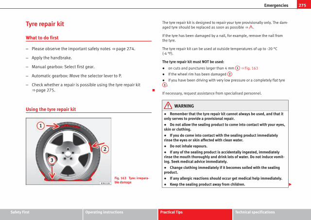
275Emergencies
Tyre repair kit
What to do first
– Please observe the important safety notes ⇒ page 274.
– Apply the handbrake.
– Manual gearbox: Select first gear.
– Automatic gearbox: Move the selector lever to P.
– Check whether a repair is possible using the tyre repair kit⇒ page 275.
Using the tyre repair kit
Fig. 163 Tyre: irrepara-ble damage
The tyre repair kit is designed to repair your tyre provisionally only. The dam-aged tyre should be replaced as soon as possible ⇒ .
If the tyre has been damaged by a nail, for example, remove the nail fromthe tyre.
The tyre repair kit can be used at outside temperatures of up to -20 °C(-4 °F).
The tyre repair kit must NOT be used:
● on cuts and punctures larger than 4 mm 1 ⇒ Fig. 163
● If the wheel rim has been damaged 2
● if you have been driving with very low pressure or a completely flat tyre3 .
If necessary, request assistance from specialised personnel.
WARNING
● Remember that the tyre repair kit cannot always be used, and that itonly serves to provide a provisional repair.
● Do not allow the sealing product to come into contact with your eyes,skin or clothing.
● If you do come into contact with the sealing product immediatelyrinse the eyes or skin affected with clean water.
● Do not inhale vapours.
● If any of the sealing product is accidentally ingested, immediatelyrinse the mouth thoroughly and drink lots of water. Do not induce vomit-ing. Seek medical advice immediately.
● Change clothing immediately if it becomes soiled with the sealingproduct.
● If any allergic reactions should occur get medical help immediately.
● Keep the sealing product away from children.
Safety First Operating instructions Practical Tips Technical specifications

276 Emergencies
Note● If sealing product should leak out, leave it to dry. This way you can pull itoff like a piece of foil.
● Observe the expiry date stated on the sealing compound can. Have thesealing compound changed by a specialised workshop or SEAT Service.
● Please observe legal requirements when doing so.
Repairing tyres
Fig. 164 Tyre: top up
Important: have the tyre repair kit ready ⇒ page 274.
Filling the tyre
– Before filling the tyre, shake the bottle of sealing product thor-oughly.
– Screw the enclosed filling hose onto the sealant can as far as itwill go. This will pierce the foil sealing on the can.
– Take the valve cap off the tyre valve and use a screwdriver⇒ Fig. 164 to unscrew the valve insert.
– Place the valve insert onto a clean surface.
– Remove the sealing plug from the filling hose and insert thehose into the tyre valve.
– Hold the bottle upside down and insert the contents in the tyreuntil the bottle is empty.
– Then disconnect the hose and screw the valve insert back ontothe tyre valve.
Inflating the tyre
– Screw the compressor filling hose (tyre repair kit) onto the tyrevalve and plug the connector into the 12V connection.
– Pump the tyre up to 2.0 to 2.5 bar and monitor the pressureshown on the pressure gauge.
– If the tyre does not reach this pressure, move the car forwardsor backwards 10 metres to allow the sealing compound tospread all around the tyre.
WARNING
● Please observe the manufacturer's safety notes on the compressorand the instructions supplied with the tyre sealant can.
● If, after six minutes of trying to inflate the tyre, it is not possible getup to a pressure of 2.0 bar, this indicates that the tyre is too severelydamaged for repair with the kit. Do not carry on driving!
● If the tyre cannot be repaired with the sealing compound, seek pro-fessional assistance.

277Emergencies
NoteDo not use the compressor for longer than 6 minutes at a time, as it couldoverheat. Once it has cooled down, the compressor may be used again.
After changing a wheel
– Attach the “max label. 80 km/h” from the tyre repair kit on theinstrument panel, clearly within driver's field of view.
– Stop the vehicle after 10 minutes driving and check the tyrepressure.
– If tyre pressure is less than 1.3 bar, the tyre is too badly dam-aged. Do not carry on driving!
WARNING
After repairing a tyre please note the following points:
● Do not drive faster than 80 km/h.
● Avoid heavy acceleration, hard braking and fast cornering.
● Vehicle handling could be impaired.
● If the tyre is very damaged, seek professional assistance.
For the sake of the environmentYou can dispose of the used bottle of sealing compound at a SEAT OfficialService.
NoteAfter repairing a tyre, remember to purchase a new bottle of sealing com-pound from a SEAT Official Service or a specialised workshop.
Changing a wheel
What to do first
Before changing the wheel, the following preliminary stepsare required.
– Please observe the important safety notes ⇒ page 274.
– Apply the handbrake.
– Manual gearbox: Select first gear.
– Automatic gearbox: Move the selector lever to P.
– When towing a trailer: Unhitch the trailer from your vehicle.
– Have the vehicle tool kit ⇒ page 274 and the spare wheel ready⇒ page 282.
WARNING
If you change the wheel on a slope, block the wheel on the opposite sideof the car with a stone or similar to prevent the vehicle from moving.
Safety First Operating instructions Practical Tips Technical specifications

278 Emergencies
Wheel covers*
The wheel covers must be removed for access to the wheelbolts
Fig. 165 Remove thecomplete hub cap
Removing
– Remove the wheel cover using the wire hook ⇒ Fig. 165.
– Hook this into one of the cut-outs of the wheel cover.
Fitting
– Fit the wheel cover onto the wheel rim by pressing it firmly. Putpressure initially on the point of the cut-out for the valve. Nextfit the rest of the hubcap
Wheel bolt caps*
Fig. 166 Wheel: wheelbolts with caps
Removal
– Fit the plastic clip (vehicle tools) over the cap until it clicks intoplace ⇒ Fig. 166.
– Remove the cap with the plastic clip.

279Emergencies
Anti-theft wheel bolts
Fig. 167 Anti-theftwheel bolt with cap andadapter
A special adapter (vehicle tools) is required to remove the anti-theft wheel bolts.
– Remove the wheel cover* or the cap*.
– Insert the adapter onto the anti-theft wheel bolt and push it onas far as it will go.
– Insert the wheel brace (vehicle tools) onto the adapter as far asit will go.
– Remove the wheel bolt ⇒ page 279.
NoteMake a note of the code number of the anti-theft wheel bolt and keep it in asafe place, but not in your vehicle. If you need a new adapter, you can ob-tain it from the SEAT Official Service, indicating the code number.
Loosening the wheel bolts
Fig. 168 Wheel: loosenthe wheel bolts
– Insert the box spanner (vehicle tools) onto the wheel bolt as faras it will go1).
– Turn the wheel bolt approximately one turn to the left ⇒ Fig. 168-arrow-. To apply the required torque, hold the wheel brace atthe end. If it is not possible to loosen a wheel bolt, carefully ap-ply pressure with one foot on the end of the box spanner. Holdon to the vehicle for support and take care not to slip.
1) An adapter is required to unscrew or tighten the anti-theft wheel bolts ⇒ page 279.
Safety First Operating instructions Practical Tips Technical specifications

280 Emergencies
WARNING
Slightly loosen the wheel bolts (one turn) before raising the vehicle withthe jack*. If not, an accident may occur.
Raising the vehicle
Fig. 169 Crossbar:marks
Fig. 170 Strut: mountingthe jack on the vehicle
– Place the jack* (vehicle tools) on a firm surface. If necessary usea large, strong board or similar support. If the surface is slip-pery (for example, tiles), use a non-slip base underneath thejack (for example, a rubber mat) ⇒ .
– Find the support point on the strut (sunken area) closest to thewheel to be changed ⇒ Fig. 169. The jack* support point is be-hind the mark on the strut.
– Turn the jack*, located below the strut support point, to raise ituntil tab A ⇒ Fig. 170 is below the housing provided.
– Align the jack* so that tab A “grips” onto the housing provi-ded on the longitudinal member and the mobile base plate B
is resting on the ground. The base plate B should fall verticallywith respect to the support point A .
– Continue turning the jack* until the wheel is slightly lifted offthe ground.

281Emergencies
WARNING
● Make sure that the jack* remains stable. If the surface is slippery orsoft, the jack* could slip or sink, respectively, with the resultant risk ofinjury.
● Only raise the vehicle with the jack* supplied by the manufacturer.Other vehicles could slip, with the consequent risk of injury.
● Only mount the jack* on the support points designed for this purposeon the strut, and always align the jack correctly. If you do not, the jack*could slip as it does not have an adequate grip on the vehicle: risk of in-jury!
● The height of the parked vehicle can change as a result of variationsin temperature and loading.
CAUTIONThe vehicle must not be raised on the crossbar. Only place the jack* on thepoints designed for this purpose on the strut. Otherwise, the vehicle may bedamaged.
Removing and fitting a wheel
After loosening the wheel bolts and raising the vehicle with thejack, change the wheel as described below:
Taking off the wheel
– Unscrew the wheel bolts using the box spanner and place themon a clean surface.
– Take off the wheel ⇒ .
Putting on the spare wheel
When fitting tyres with a compulsory rotation direction, observethe instructions in ⇒ page 281.
– Mount the wheel.
– Screw on the wheel bolts in position and tighten them looselywith a box spanner.
– Carefully lower the vehicle using the jack*.
– Tighten the wheel bolts in diagonal pairs using the wheelbrace.
The wheel bolts should be clean and turn easily. Before fitting the sparewheel, inspect the wheel condition and hub mounting surfaces. These sur-faces must be clean before fitting the wheel.
CAUTIONWhen removing/fitting the wheel, the rim may hit and damage the brakedisc. For this reason, please take care and get a second person to assistyou.
Tyres with compulsory direction of rotation
A directional tread pattern can be identified by arrows on the sidewall thatpoint in the direction of rotation. Always observe the direction of rotation in-dicated when mounting the wheel. This is important so that these tyres cangive maximum grip and avoid excessive noise, tread wear and aquaplaning.
If, exceptionally, it is necessary to mount the spare wheel* in the oppositedirection of rotation, please drive carefully, as in this case the tyre does nothave optimum conditions of use. This is particularly important when drivingon wet roads.
Safety First Operating instructions Practical Tips Technical specifications

282 Emergencies
To benefit from the advantages of tyres with this type of tread pattern, thedefective tyre should be replaced as soon as possible so that all tyres againrotate in the correct direction.
After changing a wheel
– On alloy wheels: replace the wheel bolt caps.
– On plate wheels: replace the wheel hubcap ⇒ page 278.
– Put the tools and jack back in the luggage compartment.
– If the replaced wheel does not fit in the spare wheel housing,store it safely in the luggage compartment ⇒ page 17.
– Check the tyre pressure of the newly mounted tyre as soon aspossible.
– In vehicles fitted with a tyre pressure indicator, adjust the pres-sure and store the reading in the radio/Easy Connect system*⇒ page 214.
– The wheel bolts should be tightened to 120 Nm. Check the tor-que as soon as possible with a torque wrench. Meanwhile, drivecarefully.
– Have the flat tyre replaced as quickly as possible.
Spare wheel
General information
Fig. 171 Compact tem-porary spare wheel:raised floor panel
The temporary spare wheel has been designed to be used for shortperiods of time. Have the tyres checked, and if necessary, replacedas soon as possible at a SEAT Official Service or at a specialisedworkshop.
Please note the following restrictions when using the compact tem-porary spare wheel. The compact temporary spare wheel is de-signed specifically for this model. For this reason, do not use atemporary spare wheel from a different type of vehicle.
Removing the temporary spare wheel
– Lift and hold up the floor panel to remove the temporary sparewheel ⇒ Fig. 171.
– Turn the thumb wheel anti-clockwise.

283Emergencies
– Take out the temporary spare wheel.
Chains
For technical reasons, snow chains must not be used on the temporaryspare wheel.
If you have a puncture on one of the front wheels when using snow chains,fit the temporary spare wheel in place of one of the rear wheels. Fit the snowchains on the rear wheel that you have removed and replace the puncturedfront wheel with this wheel.
WARNING
● After fitting the temporary spare wheel, check the tyre pressures assoon as possible. Failure to do so may cause an accident. The tyre pres-sures are listed on the inside of the fuel tank flap.
● Do not drive at over 80 km/h (50 mph) when the temporary sparewheel is fitted on the vehicle: risk of accident!
● Avoid heavy acceleration, hard braking and fast cornering: risk of ac-cident!
● Never use more than one temporary spare wheel at the same time,risk of accident.
● No other type of tyre (normal summer or winter tyre) may be fitted onthe compact temporary spare wheel rim.
Extraction of the spare wheel in vehicles with SEAT SOUND10 speakers (with subwoofer)*
– Disassemble the subwoofer’s floor panel (carpet) as follows:
– LEON / LEON SC model: first, pull the carpet in the direction ofthe backrest and then pull the carpet upwards to remove it.
LEON ST Model: lift and secure the luggage compartment flooras explained in ⇒ page 148.
– Disconnect the subwoofer’s speaker cable.
– Turn the securing wheel anti-clockwise.
– Remove the subwoofer speaker and the spare wheel.
– When replacing the spare wheel, place the subwoofer speakerin the direction indicated by the arrow and with the word“FRONT” facing forward.
– Reconnect the speaker cable and firmly rotate the securingwheel clockwise so that the subwoofer system and wheel arefirmly in place.
Jump starting
Jump leads
The jump lead must have a sufficient wire cross section.
If the engine fails to start because of a discharged battery, the battery canbe connected to the battery of another vehicle to start the engine.
Jump leads
Jump leads must comply with standard DIN 72553 (see cable manufactur-er's instructions). The wire cross section must be at least 25 mm2 for petrolengines and at least 35 mm2 for diesel engines.
Safety First Operating instructions Practical Tips Technical specifications

284 Emergencies
Note● The vehicles must not touch each other, otherwise electricity could flowas soon as the positive terminals are connected.
● The discharged battery must be properly connected to the on-board net-work.
How to jump start: description
Fig. 172 Diagram of con-nections for vehicleswithout Start Stop sys-tem
Fig. 173 Diagram of con-nections for vehicleswith Start Stop system
Jump lead terminal connections
1. Switch off the ignition of both vehicles ⇒ .
2. Connect one end of the red jump lead to the positive + termi-nal of the vehicle with the flat battery A ⇒ Fig. 172.
3. Connect the other end of the red jump lead to the positive ter-minal + in the vehicle providing assistance B .
4. For vehicles without Start-Stop system: Connect one end of theblack jump lead to the negative terminal – of the vehicle pro-viding assistance B ⇒ Fig. 172.
– For vehicles with Start-Stop system: Connect one end of theblack jump lead X to a suitable ground terminal, a solid pieceof metal in the engine block, or to the engine block ⇒ Fig. 173.
5. Connect the other end of the black jump lead X to a solid met-al component bolted to the engine block or to the engine blockitself of the vehicle with the flat battery. However, connect it toa point as far as possible from the battery A .

285Emergencies
6. Position the leads in such a way that they cannot come intocontact with any moving parts in the engine compartment.
Starting
7. Start the engine of the vehicle with the boosting battery and letit run at idling speed.
8. Start the engine of the vehicle with the flat battery and wait twoor three minutes until the engine is “running”.
Removing the jump leads
9. Before you remove the jump leads, switch off the dipped beamheadlights (if they are switched on).
10.Turn on the heater blower and heated rear window in the vehi-cle with the flat battery. This helps minimise voltage peakswhich are generated when the leads are disconnected.
11.When the engine is running, disconnect the leads in reverse or-der to the details given above.
Connect the battery clamps so they have good metal-to-metal contact withthe battery terminals.
If the engine fails to start, switch off the starter after about 10 seconds andtry again after about half a minute.
WARNING
● Please note the safety warnings referring to working in the enginecompartment ⇒ page 251.
● The battery providing assistance must have the same voltage as theflat battery (12V) and approximately the same capacity (see imprint onbattery). Failure to comply could result in an explosion.
● Never use jump leads when one of the batteries is frozen. Danger ofexplosion! Even after the battery has thawed, battery acid could leak andcause chemical burns. If a battery freezes, it should be replaced.
● Keep sparks, flames and lighted cigarettes away from batteries, dan-ger of explosion. Failure to comply could result in an explosion.
● Observe the instructions provided by the manufacturer of the jumpleads.
● Do not connect the negative cable from the other vehicle directly tothe negative terminal of the flat battery. The gas emitted from the batterycould be ignited by sparks. Danger of explosion.
● Do not attach the negative cable from the other vehicle to parts of thefuel system or to the brake line.
● The non-insulated parts of the battery clamps must not be allowed totouch. The jump lead attached to the positive battery terminal must nottouch metal parts of the vehicle, this can cause a short circuit.
● Position the leads in such a way that they cannot come into contactwith any moving parts in the engine compartment.
● Do not lean on the batteries. This could result in chemical burns.
NoteThe vehicles must not touch each other, otherwise electricity could flow assoon as the positive terminals are connected.
Safety First Operating instructions Practical Tips Technical specifications

286 Emergencies
Towing and tow-starting the vehicle
General information
Points to observe when tow-starting or towing away
If you use a tow rope:
Notes for the driver of the towing vehicle
– The tow rope must be taut before you drive off.
– Release the clutch very carefully when starting the vehicle(manual gearbox), or accelerate gently (automatic gearbox).
Notes for the driver of the towed vehicle
– The ignition should be switched on so that the turn signals,windscreen wipers and washers can be used. Please ensurethat the steering wheel is unlocked when you switch on the ig-nition, and that it moves freely.
– Put the gearbox lever in neutral (manual gearbox) or move theselector lever to position N (automatic gearbox).
– The brake servo only works when the engine is running. Consid-erably more effort is required on the brake pedal when the en-gine is switched off.
– Remember that the power steering only works when the ignitionis switched on and the vehicle is moving1). Otherwise, consider-ably more strength than usual will be required when steering.
– Ensure that the tow rope remains taut at all times.
Tow rope or tow bar
It is easier and safer to tow a vehicle with a tow bar. You should only use atow rope if you do not have a tow bar.
A tow rope should be slightly elastic to avoid damage to both vehicles. It isadvisable to use a tow rope made of synthetic fibre or similarly elastic mate-rial.
Only attach the tow rope or the tow bar to the towing rings ⇒ page 287.
Driving style
Towing requires some experience, especially when using a tow rope. Bothdrivers should be familiar with the technique required for towing. Inexper-ienced drivers should not attempt to tow.
Do not pull too hard with the towing vehicle and take care to avoid jerkingthe tow rope. When towing on an unpaved road, there is always a risk ofoverloading and damaging the anchorage points.
WARNING
If the vehicle has no electrical power, the brake lights, turn signals andall other lights will no longer function. Do not have the vehicle towedaway. Failure to do so could result in an accident.
CAUTIONIf there is no oil in the gearbox or no lubricant in the automatic transmissionthe car may only be towed with the driven wheels lifted clear of the road, ortransported on a special car transporter or trailer.
1) Important: the battery must be correctly charged.

287Emergencies
Note● Please observe legal requirements when doing so.
● Switch on the hazard warning lights of both vehicles. However, observeany regulations to the contrary.
● The tow rope must not be twisted. Otherwise the front towline anchor-age could be pulled off the vehicle.
Towline anchorage at the front of the vehicle
The front towline anchorage is only mounted if the vehiclehas to be towed.
Fig. 174 Right side ofthe front bumper: towlineanchorage screwed in
There is a cover with an opening into which the towline anchorageis screwed on the right part of the front bumper.
– To remove the bumper cover, just press the upper left side in-wards.
– Take the towline anchorage out of the vehicle tool kit⇒ page 274.
– Screw the towline anchorage into the screw connection as far asit will go ⇒ Fig. 174 and tighten with the wheel brace.
After use, unscrew the towline anchorage and fit the cover back on thebumper. Put the towline anchorage back in the vehicle tool kit. The towlineanchorage should always be kept in the vehicle.
Safety First Operating instructions Practical Tips Technical specifications

288 Emergencies
Rear towline anchorage
The rear towline anchorage should only be mounted if youwish to tow another vehicle.
Fig. 175 Right side ofthe rear bumper: covercap
Fig. 176 Right side ofthe rear bumper: towlineanchorage screwed in
Vehicles with towline anchorage
On the right of the rear bumper there is a cover which covers athreaded hole.
– Take the towline anchorage out of the vehicle tool set⇒ page 274.
– To remove the bumper cover, press the upper side of the coverinwards -arrow- and remove the cover by levering on the leftside ⇒ Fig. 175.
– Screw the towline anchorage into the screw connection as far asit will go ⇒ Fig. 176 and tighten with the wheel brace.
After use, unscrew the towline anchorage and put it back in the vehicle toolkit. Replace the cover on the bumper. The towline anchorage should alwaysbe kept in the vehicle.
WARNING
● If the towline anchorage is not screwed in as far as the stop, there is arisk of the screw connection shearing off during towing (accident risk).
● If your car has a towing bracket, only use special towing ropes. Riskof accident!
CAUTIONIn vehicles fitted with a towing bracket, only use special tow bars to preventdamage to the ball joint. These tow bars have been specially approved foruse with towing brackets.

289Emergencies
Tow-starting
As a general rule, tow-starting is not recommended.
– Engage 2nd or 3rd gear before moving off.
– Press the clutch and hold the pedal down.
– Switch the ignition on.
– Once both vehicles are moving, release the clutch.
– As soon as the engine starts: press the clutch and put the gearlever in neutral.
If the engine will not start, it is best to try starting it using the battery of an-other vehicle ⇒ page 283 before attempting to tow start. You should only tryto tow-start the engine if jump starting is not successful. Tow-starting is anattempt to start the engine via the movement of the wheels.
When tow-starting a vehicle with a petrol engine, do not tow it more than ashort distance, otherwise unburned fuel can enter the catalytic converterand cause damage.
WARNING
The risk of accidents is high when tow-starting, as the towed vehicle caneasily be driven into the towing vehicle.
CAUTIONDo not tow vehicles for more than 50 m. Risk of damage to the catalytic con-verter.
Towing vehicles with a manual gearbox
Towing is relatively straightforward.
Please observe the relevant instructions ⇒ page 286.
The vehicle can be towed using a tow bar or tow rope in the normal way,with all four wheels on the road; it can also be towed with either the front orrear wheels lifted off the road. The maximum towing speed is 50 km/h (30mph).
Towing a vehicle equipped with automatic gearbox
Certain restrictions must be observed when towing your ve-hicle.
Please observe the relevant instructions ⇒ page 286.
The vehicle can be towed with a tow bar or tow rope in the normal way, withall four wheels on the ground. When doing so, please note the followingpoints:
● Make sure the selector lever is in the N position.
● The vehicle must not be towed faster than 50 km/h (30 mph).
● The vehicle must not be towed further than 50 km (30 miles). Reason:when the engine is not running, the gearbox oil pump does not work andthe gearbox is not adequately lubricated for higher speeds or longer distan-ces.
If the vehicle has to be towed with a breakdown truck, it must only be sus-pended at the front wheels. Reason: the drive shafts are located on the frontwheels. If the car is towed with the rear wheels lifted off the road (I.e. travel-ling backwards), the drive shafts also turn backwards. The planetary gearsin the automatic gearbox then turn at such high speeds that the gearboxwill be severely damaged in a short time.
Safety First Operating instructions Practical Tips Technical specifications

290 Emergencies
Note● If it is not possible to tow the vehicle in the normal way, or if it has to betowed further than 50 km (30 miles), it must be transported on a special cartransporter or trailer.
● Should the power supply to the selector lever be interrupted in posi-tion P, the selector lever will be locked. Before the vehicle can be recovered/manoeuvred you must manually release the selector lever ⇒ page 182.

291Fuses and bulbs
Fuses and bulbs
Fuses
Introduction
Due to the constant update of vehicles, fuse assignments depending onequipment and the use of the same fuse for various electrical components,at the time of printing this manual it is not possible to provide an up-to-datesummary of the electrical components fuse positions. For detailed informa-tion about the fuse positions, please consult a Technical Service.
In general, a fuse can be assigned to various electrical components. Like-wise, an electrical component can be protected by several fuses.
Only replace fuses when the cause of the problem has been solved. If anewly inserted fuse blows after a short time, you must have the electricalsystem checked by a specialised workshop as soon as possible.
Additional information and warnings:
● Working in the engine compartment ⇒ page 251
WARNING
The high voltages in the electrical system can give serious electricalshocks, causing burns and even death!
● Never touch the electrical wiring of the ignition system.
● Take care not to cause short circuits in the electrical system.
WARNING
Using unsuitable fuses, repairing fuses or bridging a current circuit with-out fuses can cause a fire and serious injury.
● Never use a fuse with a higher value. Only replace fuses with a fuse ofthe same amperage (same colour and markings) and size.
● Never repair a fuse.
● Never replace a fuse by a metal strip, staple or similar.
CAUTION● To avoid damage to the vehicles electric system, before replacing a fuseturn off the ignition, the lights and all electrical elements and remove thekeys from the ignition.
● If you replace a fuse with higher-rating fuse, you could cause damage toanother part of the electrical system.
● Protect the fuse boxes when open to avoid the entry of dust or humidity.Dirt and humidity inside fuse boxes can cause damage to the electrical sys-tem.
Note● One single consumer could have more than one fuse.
● Several consumers could run over one single fuse.
Safety First Operating instructions Practical Tips Technical specifications

292 Fuses and bulbs
Vehicle fuses
Fig. 177 On the driver-side dash panel: fuse boxcover
Fig. 178 In the enginecompartment: fuse boxcover
Only replace fuses with a fuse of the same amperage (same colour andmarkings) and size.
Identifying fuses situated below the driver-side dash panel by colours
Colour Amp rating
purple 3
Light brown 5
Brown 7.5
Red 10
Blue 15
Yellow 20
White or transparent 25
Green 30
Orange 40
Opening and closing the fuse box situated below the dash panel
● Opening: fold the cover down ⇒ Fig. 177.
● Closing: push back the cover it in until it clicks into place.
To open the engine compartment fuse box
● Open the bonnet ⇒ page 251.
● Press the locking tabs to release the fuse box cover ⇒ Fig. 178.
● Then lift the cover out.
● To fit the cover, place it on the fuse box. Push the locking tabs down un-til they click audibly into place.
CAUTION● Always carefully remove the fuse box covers and refit them correctly toavoid problems with your vehicle.
● Protect the fuse boxes when open to avoid the entry of dust or humidity.Dirt and humidity inside fuse boxes can cause damage to the electrical sys-tem.

293Fuses and bulbs
NoteIn the vehicle, there are more fuses than those indicated in this chapter.These should only be changed by a specialised workshop.
Replacing a blown fuse
Fig. 179 Image of ablown fuse
Preparation
● Switch off the ignition, lights and all electrical equipment.
● Open the corresponding fuse box ⇒ page 292.
Identifying a blown fuse
A fuse is blown if its metal strip is ruptured ⇒ Fig. 179.
Point a lamp at the fuse. This will make it easier to see if the fuse is blown.
To replace a fuse
● Remove the fuse.
● Replace the blown fuse by one with an identical amperage rating (samecolour and markings) and identical size ⇒ .
● Replace the cover again or close the fuse box lid.
CAUTIONIf you replace a fuse with higher-rating fuse, you could cause damage to an-other part of the electrical system.
Bulbs
Changing a bulb
Changing bulbs requires a certain degree of practical skill.
If you choose to change engine compartment lamps yourself, rememberthat it is a dangerous area ⇒ in Working on components in the enginecompartment on page 251.
Always use identical bulbs with the same designation. The name can befound on the base of the bulb holder.
Depending on how equipped the vehicle is, there are different sets of head-lights and tail lights:
● Halogen headlights
● Full-LED main headlights*
● Rear bulb light
● LED rear light*
Safety First Operating instructions Practical Tips Technical specifications

294 Fuses and bulbs
Full-LED headlight system*
Full-LED headlights handle all light functions (daylight, side light, turn sig-nal, dipped beam and route light) with light emitting diodes (LEDs) as alight source.
Full-LED headlights are designed to last the lifetime of the car and lightbulbs cannot be replaced. In case of headlight failure, go to an authorisedworkshop to have it replaced.
Bulbs (12 V)
Halogen headlights Type
Daytime driving light/side light P21W SLL
Dipped beam headlights H7 LL
Main beam headlights H7 LL
Turn signal PY21W LL
Full-LED main headlights Type
No bulbs may be replaced. All functions arewith LEDs
Front fog light Type
Fog/cornering lights* H8
Rear bulb light Type
Brake lights/tail lights P21W LL
Side lights 2x W5W LL
Turn signal PY21W LL
Rear fog light H21W
Reverse lights P21W LL
LED rear light Type
Turn signal PY21W LL
Rear fog light H21W
LED rear light Type
Reverse lights P21W LL
The remaining functions work with LEDs
WARNING
● Take particular care when working on components in the engine com-partment if the engine is warm. Risk of burns.
● Bulbs are highly sensitive to pressure. The glass can break when youtouch the bulb, causing injury.
● When changing bulbs, please take care not to injure yourself on sharpedges, in particular on the headlight housing.
CAUTION● Remove the ignition key before working on the electric system. Other-wise, a short circuit could occur.
● Switch off the lights or parking lights before you change a bulb.
● Take good care to avoid damaging any components.
For the sake of the environmentPlease ask your specialist retailer how to dispose of used bulbs in the prop-er manner.
Note● Please check at regular intervals that all lighting (especially the exteriorlighting) on your vehicle is functioning properly. This is not only in the inter-est of your own safety, but also that of all other road users.
● Before changing a bulb, make sure you have the correct new bulb.
● Do not touch the glass part of the bulb with your bare hands, use a clothor paper towel instead. Otherwise, the fingerprints left on the glass will va-porise as a result of the heat generated by the bulb, they will be depositedon the reflector and will impair its surface.

295Fuses and bulbs
Changing bulbs in headlight unit
Dipped beam bulb
Fig. 180 Dipped beamheadlights
Fig. 181 Dipped beamheadlights
– Raise the bonnet
– Move the loops ⇒ Fig. 180 1 in the direction of the arrow andremove the cover.
– Remove connector ⇒ Fig. 181 2 from the bulb.
– Unclip the retainer spring ⇒ Fig. 181 3 pressing inwards to theright.
– Extract the bulb and fit the replacement so that the rim of theattachment plate is on the reflector cut-out.
Daylight bulb
Fig. 182 Daylight bulb
– Raise the bonnet.
– Turn bulb holder ⇒ Fig. 182 A to the left and pull.
– Remove the bulb by pressing on the bulb holder and turning itanti-clockwise at the same time.
– Installation involves all of the above steps in reverse sequence.
Safety First Operating instructions Practical Tips Technical specifications

296 Fuses and bulbs
Turn signal bulb
Fig. 183 Turn signal bulb
Fig. 184 Turn signal bulb
– Raise the bonnet
– Move the loop ⇒ Fig. 183 1 in the direction of the arrow andremove the cover.
– Turn the bulb holder ⇒ Fig. 184 2 to the left and pull.
– Remove the bulb by pressing on the bulb holder and turning itanti-clockwise at the same time.
– Installation involves all of the above steps in reverse sequence.
Main beam bulb
Fig. 185 Main beambulb
Fig. 186 Main beambulb
– Raise the bonnet
– Move the loop ⇒ Fig. 185 1 in the direction of the arrow andremove the cover.
– Slide connector ⇒ Fig. 186 2 to the left or right and pull.
– Remove the bulb by disconnecting the connector.
– Installation involves all of the above steps in reverse sequence.

297Fuses and bulbs
Changing bulb for front fog light
Front fog light bulb
Fig. 187 Front fog light
Fig. 188 Front fog light
– Remove the bolt ⇒ Fig. 187 A from the fog light grille with ascrewdriver.
– Remove the bolts (3x) ⇒ Fig. 188 B to remove the fog light.
– Remove the fog light.
NoteDue to the difficulty of accessing fog light bulbs, have them replaced at aTechnical Service or specialised workshop.
Safety First Operating instructions Practical Tips Technical specifications

298 Fuses and bulbs
Fog light, FR version
Fig. 189 Fog light: ac-cess to the connectorand to the light bulbholder
Fig. 190 Fog light: ac-cess to the connector andto the light bulb holder
– Remove the 3 screws A ⇒ Fig. 189 from the inside of the wheelhousing and the 2 bottom screws B ⇒ Fig. 189 from the bump-er using a screwdriver.
– Pull the wheel housing 1 ⇒ Fig. 190 to access the 2 hiddenscrews C ⇒ Fig. 190 in the bumper.
– Remove the screws using a screwdriver.
– Pull the bumper to release it from its anchorages to access theconnector and the light bulb holder.
NoteDue to the difficulty of accessing fog light bulbs, have them replaced at aTechnical Service or specialised workshop.
Remove the bulb holder
Fig. 191 Front fog light
– Remove connector ⇒ Fig. 191 A from the bulb.
– Turn bulb holder ⇒ Fig. 191 B to the left and pull.

299Fuses and bulbs
– Remove the bulb by pressing on the bulb holder and turning itanti-clockwise at the same time.
– Installation involves all of the above steps in reverse sequence.
– Check that the bulb works properly.
Changing tail light bulbs (on side panel)
Overview of tail lights
Rear lights on the side panel
Turn signal PY21W NA LL
Side light and brake light P21W LL
Removing tail light
Fig. 192 Luggage com-partment: Location of thebolt securing the taillight unit
Fig. 193 Remove rearlight unit from side panel
– Check which of the bulbs is defective.
– Open the rear lid.
Safety First Operating instructions Practical Tips Technical specifications

300 Fuses and bulbs
– Remove the cover by prying the flat side of a screwdriver intothe recess and remove the cover from the opening ⇒ Fig. 192
1 .
– Carefully loosen the screw located behind the cover with ascrewdriver, turning it anti-clockwise (arrows) ⇒ Fig. 192 2 .
– Tilt the light in the direction of the arrows until it comes out (po-sitions 3 and 4 ⇒ Fig. 193).
– Remove the bulb holder ⇒ page 300.
CAUTIONTake care when removing the rear light unit to make sure there is no dam-age to the paintwork or any of its components.
NoteMake sure you have a soft cloth ready to place under the glass on the rearlight unit, to avoid any scratches.
Remove the bulb holder
When changing a bulb, you must first remove the bulb hold-er.
Fig. 194 Retaining tabson reverse side of taillight
– Remove the bulb holder ⇒ Fig. 194 unlocking the A retainingtabs.
– Raise the bulb holder.
– Change the defective bulb.
– To refit follow the steps in reverse order, taking special carewhen fitting the bulb holder. And especially that all retainingtabs are properly in place.
– Place the light back into place and tighten with a screwdriver.
NoteIn the case of LED lights, change only the turn signal bulb.

301Fuses and bulbs
Changing tail light bulbs (on rear lid)
Overview of tail lights
Rear lights on tailgate
Left side
Side lights 2x W5W LL
Fog lights H21 W
Right side
Side lights 2x W5W LL
Reverse light P21W LL
The above table corresponds to a right-hand traffic vehicle. The position oflights may vary according to the country.
Remove the bulb holder
The rear lid must be open to change the bulbs.
Fig. 195 Remove thecover from the rear lid
Fig. 196 Remove thebulb holder
– Remove the rear lid cover in the direction indicated ⇒ Fig. 195.
Safety First Operating instructions Practical Tips Technical specifications

302 Fuses and bulbs
– Unlock the retaining tabs A of the bulb holder, following thedirection of arrows 1 and 2 ⇒ Fig. 196.
– Remove the bulb holder by turning it in the direction of arrow3 ⇒ Fig. 196.
Changing bulbs
Fig. 197 Position of thebulbs in the bulb holder
– Lightly press the defective bulb into the bulb holder ⇒ Fig. 1971 , then turn it to the left 2 and remove it.
– Fit the new bulb, pressing it into the bulb holder and turn it tothe right as far as it will go.
– Use a cloth to remove any fingerprints from the glass part of thebulb.
– Check that the new bulb works properly.
– Replace the bulb holder.
NoteFor LED pilots, you can only change the fog or reverse bulb, on the left orright guide.
Fitting the bulb holder
– Install the bulb holder making sure that locking clips ⇒ Fig. 196A are properly clipped on.
– Replace the cover of the rear lid lining ⇒ Fig. 195.

303Fuses and bulbs
Changing number plate light bulbs.
Fig. 198 In the rearbumper: number platelight
Fig. 199 Number platelight: remove the bulbholder
Follow the steps indicated:
1. Press the number plate light in the direction of the arrow⇒ Fig. 198.
2. Remove the number plate bulb slightly.
3. In the connector lock, turn ⇒ Fig. 199 towards arrow A and pullthe connector.
4. Rotate the bulb holder in the direction of arrow B and extract itwith the bulb.
5. Replace the defective bulb with a new bulb with the same fea-tures.
6. Insert the bulb holder in the number plate light and turn in theopposite direction of arrow B until it stops.
7. Plug the connector into the bulb holder.
NoteDepending on how equipped the vehicle is, the number plate lights may beLEDs. LEDs have an estimated life that exceeds than that of the car. If a lightwith LEDs fails, go to an authorised workshop for replacement.
Safety First Operating instructions Practical Tips Technical specifications
304 Technical specifications
Technical specifications
Technical specifications
Important
The information in the vehicle documentation always takesprecedence over the information in this Instruction Manual.
All technical specifications provided in this documentation are valid for thestandard model in Spain. The vehicle data card included in the Mainte-nance Programme or the vehicle registration documentation shows whichengine is installed in the vehicle.
The figures may be different depending whether additional equipment is fit-ted, for different models, for special vehicles and for other countries.
Abbreviations used in the Technical Specifications section
Abbrevia-tion
Meaning
kW Kilowatt, engine power measurement.
PSPferdestärke (horsepower), formerly used to denote enginepower.
rpm Revolutions per minute - engine speed.
Nm Newton metres, unit of engine torque.
litres per100 km
Fuel consumption in litres per 100 km (70 miles).
g/km Carbon dioxide emissions in grams per km (mile) travelled.
CO2 Carbon dioxide
CN Cetane number, indication of the diesel combustion power.
RONResearch octane number, indication of the knock resistanceof petrol.

305Technical specifications
Vehicle identification data
Fig. 200 Vehicle datasticker (luggage compart-ment)
Fig. 201 Chassis num-ber.
Chassis number in the Easy Connect
– Select: Function button CAR > control button (Car)* Systems >Service & Control > Chassis number.
Chassis number
The vehicle identification number is located in the Easy Connect, on the ve-hicle data sticker and under the windscreen, on the driver side ⇒ Fig. 201.Additionally, the chassis number is located in the engine compartment, onthe right-hand side. The number is engraved on the top side rail, and is par-tially covered.
Type plate
The type plate is located on the right side door pillar. Vehicles for certainexport countries do not have a type plate.
Vehicle data sticker
The vehicle data sticker is under the carpet trim in the luggage compart-ment, in the spare wheel well. A sticker with the vehicle data is attached tothe inside cover of the Maintenance Programme.
The following information is provided on the vehicle data sticker: ⇒ Fig. 200
Vehicle identification number (chassis number)
Vehicle type, model, displacement, engine type, finish, engine powerand gearbox type
Engine code, gearbox code, external paint code and internal equipmentcode
Optional extras and PR numbers
Consumption values (l/100 km) and CO2 emissions (g/km)
A Urban consumption and CO2 emissions
B Extra-urban consumption and CO2 emissions
C Combined consumption and CO2 emissions
1
2
3
4
5
Safety First Operating instructions Practical Tips Technical specifications

306 Technical specifications
Identifying letters
The identifying letters of the engine can be viewed on the instrument panel.
Important: The engine must be off and the ignition on.
● Hold down the 0.0/SET 4 ⇒ Fig. 38 button for more than 15 seconds.
Information on fuel consumption
Fuel consumption
The consumption and emission details shown on the vehicledata sticker differ from one vehicle to another.
The vehicle fuel consumption and CO2 emissions can be consulted on thevehicle data sticker in the spare wheel well, inside the luggage compart-ment and on the rear cover of the Maintenance Programme.
The fuel consumption and CO2 emission values refer to the weight categoryassigned to your vehicle according to the engine and gearbox combination,as well as the specific equipment fitted, and is only used to compare be-tween the different models.
The fuel consumption and CO2 emissions do not depend only on the per-formance of the vehicle, they can also differ from the established values de-pending on other factors such as driving style, road conditions, traffic con-ditions, environmental conditions, load and number of passengers.
Calculation of fuel consumption
The consumption values have been calculated based on measurements per-formed or supervised by certified CE laboratories according to the latest ver-sion of directives 715/2007/EC and 80/1268/CEE (for more informationconsult the European Union Publications Office at EUR-Lex: © European Un-
ion, http://eur-lex.europa.eu/en/index.htm) and are valid for the kerbweight indicated for the vehicle.
NoteIn practice, and considering all the factors mentioned here, consumptionvalues can differ from those calculated in the current European regulations.
Weights
Kerb weight refers to the basic model with a fuel tank filled to 90% capacityand without optional extras. The figure quoted includes 75 kg to allow forthe weight of the driver.
For special versions and optional equipment fittings or for the addition ofaccessories, the weight of the vehicle will increase ⇒ .
WARNING
● Please note that the centre of gravity may shift when transportingheavy objects; this may affect vehicle handling and lead to an accident.Always adjust your speed and driving style to suit road conditions and re-quirements.
● Never exceed the gross axle weight rating or the gross vehicle weightrating. If the allowed axle load or the allowed total weight is exceeded,the driving characteristics of the vehicle may change, leading to acci-dents, injuries and damage to the vehicle.

307Technical specifications
Towing a trailer
Trailer weights
Trailer weight
The trailer weights and drawbar loads approved are selected in intensive tri-als according to precisely defined criteria. The approved trailer weights arevalid for vehicles in the EU for maximum speeds of 80 km/h (50 mph) (incertain circumstances up to 100 km/h, 60 mph). The figures may be differ-ent in other countries. All data in the official vehicle documentation takesprecedence over these data at all times ⇒ .
Drawbar loads
The maximum permitted drawbar load on the ball joint of the towing bracketmust not exceed 80 kg.
In the interest of road safety, we recommend that you always tow approach-ing the maximum drawbar load. The response of the trailer on the road willbe poor if the drawbar load is too small.
If the maximum permissible drawbar load cannot be met (e.g. with small,empty and light-weight single axle trailers or tandem axle trailers with awheelbase of less than 1 metre), a minimum of 4% of the actual trailerweight is legally required for the drawbar load.
WARNING
● For safety reasons, do not exceed the 80 km/h (50 mph) limit. This isalso valid in countries where higher speeds are permitted.
● Never exceed the maximum trailer weights or the drawbar load. If thepermissible axle load or the permissible total weight is exceeded, thedriving characteristics of the vehicle may change, leading to accidents,injuries and damage to the vehicle.
Wheels
Tyre pressure, snow chains, wheel bolts
Tyre pressures
The sticker with the tyre pressure values can be found on the inside of thefuel tank flap. The tyre pressure values given there are for cold tyres. Theslightly raised pressures of warm tyres must not be reduced. ⇒
Snow chains
Snow chains may be fitted only to the front wheels, and only for the follow-ing tyres:
195/65 R15 Chains with links of maximum 15 mm
205/55 R16 Chains with links of maximum 15 mm
225/45 R17 Chains with links of maximum 9 mm
225/40 R18 Chains with links of maximum 9 mm
Wheel bolts
After the wheels have been changed, the tightening torque of the wheelbolts should be checked as soon as possible with a torque wrench ⇒ .The tightening torque for steel and alloy wheels is 120 Nm.
WARNING
● Check the tyre pressure at least once per month. Checking the tyrepressure is very important. If the tyre pressure is too high or too low,there is an increased danger of accidents, particularly at high speeds.
● If the tightening torque of the wheel bolts is too low, they could loos-en while the vehicle is in motion. Risk of accident! If the tightening tor-que is too high, the wheel bolts and threads can be damaged.
Safety First Operating instructions Practical Tips Technical specifications

308 Technical specifications
NoteWe recommend that you ask your Technical Service for information aboutappropriate wheel, tyre and snow chain size.

309Technical specifications
Engine specifications
Checking fluid levels
From time to time, the levels of the different fluids in the ve-hicle must be checked. Never fill with incorrect fluids, other-wise serious damage to the engine may be caused.
Fig. 202 Diagram for the location of the various elements
Coolant expansion tank
Engine oil dipstick
Engine oil filler cap
Brake fluid reservoir
Vehicle battery (underneath the cover)
Windscreen washer reservoir
The checking and refilling of service fluids are carried out on the compo-nents mentioned above. These operations are described in ⇒ page 251.
1
2
3
4
5
6
Overview
You will find further explanations, instructions and restrictions on the tech-nical specifications as of ⇒ page 304.
Safety First Operating instructions Practical Tips Technical specifications

310 Technical specifications
Petrol engine 1.2 63 kW (85 PS)
Engine specifications
Power output in kW (PS) at rpm Maximum torque (Nm at rpm) No. of cylinders/capacity (cm3) Fuel
63 (85)/ 4300-5300 160/ 1400-3500 4/1197 Super 95 RONa)
a) Research Octane Number = Anti-detonation rating of the petrol.
Performance LEON LEON SC LEON ST
Top speed (km/h) 178 (V) 178 (V) 178 (V)
Acceleration from 0-80 km/h (seconds) 7.6 7.5 7.8
Acceleration from 0-100 km/h (seconds) 11.9 11.8 12.1
Weights (in kg)
Gross vehicle weight 1690 1700 1800
Weight in running order (with driver) 1188 1168 1233
Gross front axle weight 880 880 890
Gross rear axle weight 860 870 960
Permitted roof load 75 75 75
Maximum trailer weights (in kg)
Trailer without brakes 590 580 610
Trailer with brakes, gradients up to 8% 1300 1300 1300
Trailer with brakes, gradients up to 12% 1100 1100 1100

311Technical specifications
Petrol engine 1.2 77 kW (105 PS)
Engine specifications
Power output in kW (PS) at rpm Maximum torque (Nm at rpm) No. of cylinders/capacity (cm3) Fuel
77 (105)/ 4500-5500 175/ 1400-4000 4/1197 Super 95 RONa)
a) Research Octane Number = Anti-detonation rating of the petrol.
PerformanceLEON
ManualLEON
Start-StopLEON
AutomaticLEON SCManual
LEON SCStart-Stop
LEON SCAutomatic
LEON STManual
LEON STStart-Stop
LEON STAutomatic
Top speed(km/h)
191 (V) 191 (V) 191 (VI) 191 (V) 191 (V) 191 (V) 191 (V) 191 (V) 191 (VI)
Acceleration from 0-80km/h (seconds)
6.7 6.8 6.8 6.7 6.7 6.7 6.9 6.8 7.0
Acceleration from 0-100km/h (seconds)
10.1 10.2 10 10 10 10 10.4 10.3 10.3
Weights (in kg)
Gross vehicle weight 1720 1720 1750 1710 1710 1730 1810 1820 1850
Weight in running order(with driver)
1199 1209 1235 1179 1189 1215 1244 1254 1280
Gross front axle weight 890 890 920 880 890 920 880 890 920
Gross rear axle weight 880 880 880 880 870 860 980 980 980
Permitted roof load 75 75 75 75 75 75 75 75 75
Maximum trailer weights (in kg)
Trailer without brakes 590 590 610 580 590 600 620 620 640
Trailer with brakes, gra-dients up to 8%
1500 1500 1500 1500 1500 1500 1500 1500 1500
Trailer with brakes, gra-dients up to 12%
1300 1300 1300 1300 1300 1300 1300 1300 1300
Safety First Operating instructions Practical Tips Technical specifications

312 Technical specifications
Petrol engine 1.4 90 kW (122 PS) Start-Stop
Engine specifications
Power output in kW (PS) at rpm Maximum torque (Nm at rpm) No. of cylinders/capacity (cm3) Fuel
90 (122)/ 5000-6000 200/ 1400-4000 4/1395 Super 95 RONa)
a) Research Octane Number = Anti-detonation rating of the petrol.
Performance LEONStart-Stop
LEON SCStart-Stop
LEON STStart-Stop
Top speed (km/h) 202 (V&VI) 202 (V&VI) 202 (V&VI)
Acceleration from 0-80 km/h (seconds) 6.3 6.2 6.5
Acceleration from 0-100 km/h (seconds) 9.3 9.1 9.6
Weights (in kg)
Gross vehicle weight 1740 1710 1840
Weight in running order (with driver) 1224 1204 1269
Gross front axle weight 910 910 910
Gross rear axle weight 880 850 980
Permitted roof load 75 75 75
Maximum trailer weights (in kg)
Trailer without brakes 610 600 630
Trailer with brakes, gradients up to 8% 1700 1700 1700
Trailer with brakes, gradients up to 12% 1400 1400 1400

313Technical specifications
Petrol engine 1.4 103 kW (140 PS) Start-Stop
Engine specifications
Power output in kW (PS) at rpm Maximum torque (Nm at rpm) No. of cylinders/capacity (cm3) Fuel
103 (140)/ 4500-6000 250/ 1500-3500 4/1395 Super 95 RONa)/Normal 91 RONb)
a) Research Octane Number = Anti-detonation rating of the petrol.b) With a slight power loss
Performance LEONStart-Stop
LEON SCStart-Stop
LEON STStart-Stop
Top speed (km/h) 211 (VI) 211 (VI) 211 (VI)
Acceleration from 0-80 km/h (seconds) 5.7 5.6 5.9
Acceleration from 0-100 km/h (seconds) 8.2 8.1 8.4
Weights (in kg)
Gross vehicle weight 1730 1740 1840
Weight in running order (with driver) 1231 1211 1275
Gross front axle weight 920 910 910
Gross rear axle weight 860 880 980
Permitted roof load 75 75 75
Maximum trailer weights (in kg)
Trailer without brakes 610 600 630
Trailer with brakes, gradients up to 8% 1800 1800 1800
Trailer with brakes, gradients up to 12% 1500 1500 1500
Safety First Operating instructions Practical Tips Technical specifications

314 Technical specifications
Petrol engine 1.8 132 kW (180 PS) Start-Stop
Engine specifications
Power output in kW (PS) at rpm Maximum torque (Nm at rpm) No. of cylinders/capacity (cm3) Fuel
132 (180)/ 4000-6200 250/ 1500-3900 4/1798 Super 95 RONa)
a) Research Octane Number = Anti-detonation rating of the petrol.
Performance LEONManual
LEONAutomatic
LEON SCManual
LEON SCAutomatic
LEON STManual
LEON STAutomatic
Top speed (km/h) 226 (VI) 224 (VI) 226 (VI) 224 (VI) 226 (VI) 224 (VI)
Acceleration from 0-80 km/h (sec-onds)
5.5 5.3 5.4 5.2 5.7 5.6
Acceleration from 0-100 km/h (sec-onds)
7.5 7.2 7.4 7.1 7.8 7.7
Weights (in kg)
Gross vehicle weight 1830 1850 1830 1850 1870 1890
Weight in running order (with driv-er)
1310 1327 1290 1307 1355 1372
Gross front axle weight 970 980 960 980 960 970
Gross rear axle weight 910 920 920 920 960 970
Permitted roof load 75 75 75 75 75 75
Maximum trailer weights (in kg)
Trailer without brakes 640 660 640 650 670 680
Trailer with brakes, gradients up to8%
1800 1800 1800 1800 1800 1800
Trailer with brakes, gradients up to12%
1500 1500 1500 1500 1500 1500

315Technical specifications
Petrol engine / CNG 1.4 81 kW (110 PS)1)
Engine specifications
Power output in kW (PS) at rpm Maximum torque (Nm at rpm) No. of cylinders/capacity (cm3) Fuel
81 (110)/ 5000 200/ 1500-4000 4/1395 CNG Super 95 RONa)
a) Research Octane Number = Anti-detonation rating of the petrol.
Performance LEON
Top speed (km/h) 194 (V)
Acceleration from 0-80 km/h (seconds) 7
Acceleration from 0-100 km/h (seconds) 10.7
Weights (in kg)
Gross vehicle weight 1840
Weight in running order (with driver) 1359
Gross front axle weight 910
Gross rear axle weight 980
Permitted roof load 75
Maximum trailer weights (in kg)
Trailer without brakes 670
Trailer with brakes, gradients up to 8% 1700
Trailer with brakes, gradients up to 12% 1400
1) Provisional data as this edition goes to print.
Safety First Operating instructions Practical Tips Technical specifications

316 Technical specifications
Diesel engine 1.6 66 kW (90 PS)
Engine specifications
Power output in kW (PS) at rpm Maximum torque (Nm at rpm) No. of cylinders/capacity (cm3) Fuel
66 (90) /2750-4800 230/1400-2750 4/1598Diesel according to standard EN 590,
Min. 51 CN
Performance LEON LEON SC LEON ST
Top speed (km/h) 178 (IV) 178 (IV) 178 (IV)
Acceleration from 0-80 km/h (seconds) 8.2 8.0 8.5
Acceleration from 0-100 km/h (seconds) 12.6 12.4 13.0
Weights (in kg)
Gross vehicle weight 1800 1780 1860
Weight in running order (with driver) 1281 1261 1326
Gross front axle weight 970 970 970
Gross rear axle weight 880 860 940
Permitted roof load 75 75 75
Maximum trailer weights (in kg)
Trailer without brakes 640 620 660
Trailer with brakes, gradients up to 8% 1700 1700 1700
Trailer with brakes, gradients up to 12% 1400 1400 1400

317Technical specifications
Diesel engine 1.6 77 kW (105 PS)
Engine specifications
Power output in kW (PS) at rpm Maximum torque (Nm at rpm) No. of cylinders/capacity (cm3) Fuel
77 (105) /3000-4000 250/1750-2750 4/1598Diesel according to standard EN 590,
Min. 51 CN
PerformanceLEON
ManualLEON
Start-StopLEON
AutomaticLEON SCManual
LEON SCStart-Stop
LEON SCAutomatic
LEON STManual
LEON STStart-Stop
LEON STAutomatic
Top speed(km/h)
191 (V) 192 (V) 191 (V) 191 (V) 192 (V) 191 (V) 191 (V) 191 (V) 191 (V)
Acceleration from 0-80km/h (seconds)
7.3 7.3 7.3 7.2 7.2 7.2 7.5 7.5 7.4
Acceleration from 0-100km/h (seconds)
10.7 10.7 10.7 10.6 10.6 10.6 11.1 11.1 11.0
Weights (in kg)
Gross vehicle weight 1790 1800 1810 1780 1790 1800 1860 1860 1890
Weight in running order(with driver)
1281 1286 1306 1261 1266 1286 1326 1331 1351
Gross front axle weight 970 980 1000 970 970 990 970 970 990
Gross rear axle weight 870 870 860 860 870 860 940 940 950
Permitted roof load 75 75 75 75 75 75 75 75 75
Maximum trailer weights (in kg)
Trailer without brakes 640 640 650 630 630 640 660 660 670
Trailer with brakes, gradi-ents up to 8%
1700 1800 1800 1800 1800 1800 1800 1800 1800
Trailer with brakes, gradi-ents up to 12%
1400 1500 1500 1500 1500 1500 1500 1500 1500
Safety First Operating instructions Practical Tips Technical specifications

318 Technical specifications
Diesel engine 1.6 81 kW (110 PS) CR Ecomotive
Engine specifications
Power output in kW (PS) at rpm Maximum torque (Nm at rpm) No. of cylinders/capacity (cm3) Fuel
81 (110) /3200-4000 250/1500-3000 4/1598Diesel according to standard EN 590,
Min. 51 CN
Performance LEON LEON SC LEON ST
Top speed (km/h) 197 (V) 197 (V) 197 (V)
Acceleration from 0-80 km/h (seconds) 7 6.9 7.1
Acceleration from 0-100 km/h (seconds) 10.5 10.4 10.6
Weights (in kg)
Gross vehicle weight 1730 1730 1750
Weight in running order (with driver) 1260 1240 1280
Gross front axle weight 960 960 940
Gross rear axle weight 820 820 860
Permitted roof load 75 75 75
Maximum trailer weights (in kg)
Trailer without brakes 630 620 640
Trailer with brakes, gradients up to 8% 1300 1300 1300
Trailer with brakes, gradients up to 12% 1000 1000 1000

319Technical specifications
Diesel engine 2.0 TDI CR 81 kW (110 PS)
Engine specifications
Power output in kW (PS) at rpm Maximum torque (Nm at rpm) No. of cylinders/capacity (cm3) Fuel
81 (110) /3100-4500 250/1500-3000 4/1968Diesel according to standard EN 590,
Min. 51 CN
Performance LEON LEON SC LEON ST
Top speed (km/h) 189 (V) 189 (V) 189 (V)
Acceleration from 0-80 km/h (seconds) 7.1 6.9 7.1
Acceleration from 0-100 km/h (seconds) 10.4 10.3 10.7
Weights (in kg)
Gross vehicle weight 1780 1780 1850
Weight in running order (with driver) 1273 1253 1318
Gross front axle weight 970 960 960
Gross rear axle weight 870 870 940
Permitted roof load 75 75 75
Maximum trailer weights (in kg)
Trailer without brakes 630 620 650
Trailer with brakes, gradients up to 8% 1800 1800 1800
Trailer with brakes, gradients up to 12% 1500 1500 1500
Safety First Operating instructions Practical Tips Technical specifications

320 Technical specifications
Diesel engine 2.0 TDI CR 105 kW (143 PS)
Engine specifications
Power output in kW (PS) at rpm Maximum torque (Nm at rpm) No. of cylinders/capacity (cm3) Fuel
105 (143) /3500-4000 320/1750-3000 4/1968Diesel according to standard EN 590,
Min. 51 CN
Performance LEON LEON SC LEON ST
Top speed (km/h) 211 (V) 211 (V) 211 (V)
Acceleration from 0-80 km/h (seconds) 6.2 6.1 6.4
Acceleration from 0-100 km/h (seconds) 8.7 8.6 9.0
Weights (in kg)
Gross vehicle weight 1800 1800 1920
Weight in running order (with driver) 1301 1281 1346
Gross front axle weight 1000 990 990
Gross rear axle weight 850 860 980
Permitted roof load 75 75 75
Maximum trailer weights (in kg)
Trailer without brakes 650 640 670
Trailer with brakes, gradients up to 8% 1800 1800 1800
Trailer with brakes, gradients up to 12% 1600 1600 1600

321Technical specifications
Diesel engine 2.0 110 kW (150 PS)
Engine specifications
Power output in kW (PS) at rpm Maximum torque (Nm at rpm) No. of cylinders/capacity (cm3) Fuel
110 (150) /3500-4000 320/1750-3000 4/1968Diesel according to standard EN 590,
Min. 51 CN
PerformanceLEON
ManualLEON
Start-StopLEON
AutomaticLEON SCManual
LEON SCStart-Stop
LEON SCAutomatic
LEON STManual
LEON STStart-Stop
LEON STAutomatic
Top speed(km/h)
215 (VI) 215 (VI) 211 (VI) 215 (VI) 215 (VI) 211 (VI) 215 (VI) 215 (VI) 211 (VI)
Acceleration from 0-80km/h (seconds)
6.1 6.1 6 6 6 6 6.2 6.2 6.2
Acceleration from 0-100km/h (seconds)
8.4 8.4 8.4 8.3 8.3 8.3 8.6 8.6 8.6
Weights (in kg)
Gross vehicle weight 1800 1810 1840 1800 1810 1830 1910 1920 1950
Weight in running order(with driver)
1300 1305 1335 1280 1285 1315 1345 1350 1380
Gross front axle weight 1000 1000 1030 990 990 1020 990 990 1020
Gross rear axle weight 850 860 860 860 870 860 970 980 980
Permitted roof load 75 75 75 75 75 75 75 75 75
Maximum trailer weights (in kg)
Trailer without brakes 650 650 660 640 640 650 670 670 680
Trailer with brakes, gra-dients up to 8%
1800 1800 1800 1800 1800 1800 1800 1800 1800
Trailer with brakes, gra-dients up to 12%
1600 1600 1600 1600 1600 1600 1600 1600 1600
Safety First Operating instructions Practical Tips Technical specifications

322 Technical specifications
2.0 135 kW (184 HP) Start-Stop diesel engine
Engine specifications
Power output in kW (PS) at rpm Maximum torque (Nm at rpm) No. of cylinders/capacity (cm3) Fuel
135 (184) /3500-4000 380/1750-3000 4/1968Diesel according to standard EN 590,
Min. 51 CN
Performance LEONStart-Stop
LEONAutomatic
LEON SCStart-Stop
LEON SCAutomatic
LEON STStart-Stop
LEON STAutomatic
Top speed (km/h) 228 (VI) 228 (VI) 228 (VI) 228 (VI) 228 (VI) 228 (VI)
Acceleration from 0-80 km/h (sec-onds)
5.7 5.7 5.6 5.6 5.9 5.9
Acceleration from 0-100 km/h (sec-onds)
7.5 7.5 7.4 7.4 7.8 7.8
Weights (in kg)
Gross vehicle weight 1850 1870 1840 1860 1980 1990
Weight in running order (with driv-er)
1370 1390 1350 1370 1415 1435
Gross front axle weight 1020 1020 1020 1020 1020 1020
Gross rear axle weight 880 880 870 870 1010 1010
Permitted roof load 75 75 75 75 75 75
Maximum trailer weights (in kg)
Trailer without brakes 670 690 670 680 700 710
Trailer with brakes, gradients up to8%
1800 1800 1800 1800 1800 1800
Trailer with brakes, gradients up to12%
1600 1600 1600 1600 1600 1600

323Technical specifications
Dimensions
LEON LEON SC LEON ST
Length / Width (mm) 4263/1816 4228/1810 4535/1816
Height at kerb weight (mm) 1459 1446 1454a)
Front and rear projections(mm)
853/774 853/774 853/1046
Wheelbase (mm) 2636 2601 2636
Turning circle diameter (m) 10.9
Front/rearb) track width(mm)
1533 / 15041549 / 1520
a) Dimension to the roof bars.b) This data will change depending on the type of wheel rim.
Filling capacities
Fuel tank capacity
Petrol and diesel engines 50 l, of which approx. 7 l are reserve
Natural gas enginea) approx. 15 Kg
a) The capacity depends on the efficacy and characteristics of the natural gas pumps. The ca-pacity given is based on a minimum loading pressure of 200 bars.
Windscreen washer fluid con-tainer with headlight washer
a)
a) Data not available as this edition goes to print
Tyre pressure
Summer tyres:Correct tyre pressure can be seen on the sticker on the inside of the tankflap.
Winter tyres:The pressure of these tyres is 0.2 bar higher than that of summer tyres(2.9 psi / 20 kPa).
Safety First Operating instructions Practical Tips Technical specifications


Index
AABS
see Anti-lock brake system . . . . . . . . . . . . 222
ACC . . . . . . . . . . . . . . . . . . . . . . . . . . . . . . . . . . 189radar sensor . . . . . . . . . . . . . . . . . . . . . . . . 191
Accessories . . . . . . . . . . . . . . . . . . . . . . . . . . . . 135
Acoustic parking aid . . . . . . . . . . . . . . . . . . . . 217
Acoustic warningsHeadlights . . . . . . . . . . . . . . . . . . . . . . . . . 111
Adaptive cruise control . . . . . . . . . . . . . . . . . . 189control lamp . . . . . . . . . . . . . . . . . . . . . . . . 190malfunction . . . . . . . . . . . . . . . . . . . . . . . . 190messages on the display . . . . . . . . . . . . . . 190radar sensor . . . . . . . . . . . . . . . . . . . . . . . . 191Special driving situations . . . . . . . . . . . . . 199switching off temporarily . . . . . . . . . . . . . . 198using . . . . . . . . . . . . . . . . . . . . . . . . . . . . . . 193warning lamp . . . . . . . . . . . . . . . . . . . . . . . 190
Additional electrical appliances (efficiency pro-gramme) . . . . . . . . . . . . . . . . . . . . . . . . . . . . . 77
Adjustingfront head restraints . . . . . . . . . . . . . . . . . 131front seats . . . . . . . . . . . . . . . . . . . . . . . . . . 129rear head restraints . . . . . . . . . . . . . . . . . . 132
Adjusting the head restraintsFront head restraints . . . . . . . . . . . . . . . . . 131
Airbag . . . . . . . . . . . . . . . . . . . . . . . . . . . . . . . . . 31
Airbag covers . . . . . . . . . . . . . . . . . . . . . . . . . . . 38
Airbag system . . . . . . . . . . . . . . . . . . . . . . . . . . . 31Control lamp . . . . . . . . . . . . . . . . . . . . . . . . . 34curtain airbags . . . . . . . . . . . . . . . . . . . . . . . 43Differences between front passenger front
airbag systems . . . . . . . . . . . . . . . . . . . . . 33Front airbags . . . . . . . . . . . . . . . . . . . . . . . . 36Knee airbag . . . . . . . . . . . . . . . . . . . . . . . . . 39side airbags . . . . . . . . . . . . . . . . . . . . . . . . . 40
Air pressure (tyres) . . . . . . . . . . . . . . . . . . . . . . 265
Alarm system . . . . . . . . . . . . . . . . . . . . . . . . . . . 95
Alcantara: cleaning . . . . . . . . . . . . . . . . . . . . . 245
Ambient lighting . . . . . . . . . . . . . . . . . . . . . . . 118
Anti-dazzle rear vision mirror . . . . . . . . . . . . . . 126
Anti-freeze protectionWindscreen washer system . . . . . . . . . . . . 262
Anti-lock brake system . . . . . . . . . . . . . . . . . . . 222
Anti-theft alarm . . . . . . . . . . . . . . . . . . . . . . 87, 95see also Anti-theft alarm system . . . . . . . . . 87
Anti-theft alarm systemInterior monitoring . . . . . . . . . . . . . . . . . . . . 97Tow-away protection . . . . . . . . . . . . . . . . . . 97
Anti-theft security system . . . . . . . . . . . . . . 87, 98
Anti-theft wheel bolts . . . . . . . . . . . . . . . . . . . 279
Antifreeze . . . . . . . . . . . . . . . . . . . . . . . . . . . . . 257
Aspects to take into account before starting thevehicle . . . . . . . . . . . . . . . . . . . . . . . . . . . . . . . . 8
ASRsee Traction control system . . . . . . . . . . . . 222
Assistance systems . . . . . . . . . . . . . . . . . . . . . 184ACC . . . . . . . . . . . . . . . . . . . . . . . . . . . . . . . 189adaptive cruise control . . . . . . . . . . . . . . . 189Cruise control . . . . . . . . . . . . . . . . . . . . . . . 184monitoring system Front Assist . . . . . . . . . 202Parking aid . . . . . . . . . . . . . . . . . . . . . . . . . 218
Assisted starting . . . . . . . . . . . . . . . . . . . . . . . 283
Assist systemsTyre monitoring indicator . . . . . . . . . . . . . . 216
Audible warning . . . . . . . . . . . . . . . . . . . . . . . . . 21
Auto Lock (central locking) . . . . . . . . . . . . . . . . 87
Automatic car washessee Washing . . . . . . . . . . . . . . . . . . . . . . . . 238
Automatic dipped beam control . . . . . . . . . . . 112
Automatic gearbox . . . . . . . . . . . . . . . . . . . . . . 173Backup programme . . . . . . . . . . . . . . . . . . 181Downhill speed control . . . . . . . . . . . . . . . 178Driving tips . . . . . . . . . . . . . . . . . . . . . . . . . 176Kick-down feature . . . . . . . . . . . . . . . . . . . . 179Launch Control Programme . . . . . . . . . . . . 179Manual release of selector lever . . . . . . . . 182Safety interlock for ignition key . . . . . . . . . 163Selector lever lock . . . . . . . . . . . . . . . . . . . 175Selector lever positions . . . . . . . . . . . . . . . 173Steering wheel with gearshift paddles . . . 178tiptronic . . . . . . . . . . . . . . . . . . . . . . . 173, 178
BBack support . . . . . . . . . . . . . . . . . . . . . . . . . . 129
325Index

Balanced (wheels) . . . . . . . . . . . . . . . . . . . . . . 265
Ball coupling . . . . . . . . . . . . . . . . . . . . . . . . . . . 235
Battery . . . . . . . . . . . . . . . . . . . . . . . . . . . . . . . . 260Assisted starting . . . . . . . . . . . . . . . . . . . . 283Charge Level . . . . . . . . . . . . . . . . . . . . . . . . 226Charging . . . . . . . . . . . . . . . . . . . . . . . . . . . 261Disconnecting/Connecting . . . . . . . . . . . . 260Power Management . . . . . . . . . . . . . . . . . . 226Replacement . . . . . . . . . . . . . . . . . . . . . . . . 262Winter conditions . . . . . . . . . . . . . . . . . . . . 260
Before starting the vehicle . . . . . . . . . . . . . . . . . 8
Bench seat . . . . . . . . . . . . . . . . . . . . . . . . . . . . 138
Biodiesel . . . . . . . . . . . . . . . . . . . . . . . . . . . . . . 247
Brakes . . . . . . . . . . . . . . . . . . . . . . . . . . . . . . . . 224Brake fluid . . . . . . . . . . . . . . . . . . . . . . . . . 259Brake servo . . . . . . . . . . . . . . . . . . . . . . . . . 224New brake pads . . . . . . . . . . . . . . . . . . . . . 224
BrakingBrake assist system . . . . . . . . . . . . . . . . . . 222Hill driving assistant . . . . . . . . . . . . . . . . . 168
CCarbon components: Cleaning . . . . . . . . . . . . 241
Care . . . . . . . . . . . . . . . . . . . . . . . . . . . . . . . . . . 238
Care of vehicle . . . . . . . . . . . . . . . . . . . . . . . . . 238
Care (paint care) . . . . . . . . . . . . . . . . . . . . . . . . 240
Catalytic converter . . . . . . . . . . . . . . . . . . . . . . 230
CD-ROM player (navigation) . . . . . . . . . . . . . . 134
Central lockingAnti-theft alarm . . . . . . . . . . . . . . . . . . . . . . 95Central locking switch . . . . . . . . . . . . . . . . . 94
Electric windows . . . . . . . . . . . . . . . . . . . . . 103Programming . . . . . . . . . . . . . . . . . . . . . . . . 93Remote control key . . . . . . . . . . . . . . . . . . . . 92Selective unlocking system . . . . . . . . . . . . . 92Sliding/tilting sunroof . . . . . . . . . . . . . . . . 103
Central locking system . . . . . . . . . . . . . . . . . . . . 87Manual locking in an emergency . . . . . . . . 99Rear lid . . . . . . . . . . . . . . . . . . . . . . . . . . . . 100
Cetane number (Diesel fuel) . . . . . . . . . . . . . . 247
ChangingWindscreen and rear window wiper blades . .263
Changing a bulb . . . . . . . . . . . . . . . . . . . . . . . . 293Bulb sizes . . . . . . . . . . . . . . . . . . . . . . . . . . 293
Changing gearEngaging gears (manual gearbox) . . . . . . 172Manual gearbox . . . . . . . . . . . . . . . . . . . . . 172
Changing main headlightmain beam . . . . . . . . . . . . . . . . . . . . . . . . . 296turn signal . . . . . . . . . . . . . . . . . . . . . . . . . . 296
Changing main headlight bulbsdaylight bulb . . . . . . . . . . . . . . . . . . . . . . . 295Dipped beam . . . . . . . . . . . . . . . . . . . . . . . 295
Changing the batteryof the vehicle key . . . . . . . . . . . . . . . . . . . . . 91
Chassis number . . . . . . . . . . . . . . . . . . . . . . . . 305
Child-proof lockElectric windows . . . . . . . . . . . . . . . . . . . . . 102
Child safety . . . . . . . . . . . . . . . . . . . . . . . . . . . . . 48
Child seatCategorisation in groups . . . . . . . . . . . . . . . 50Group 1 . . . . . . . . . . . . . . . . . . . . . . . . . . . . . 51Group 2 . . . . . . . . . . . . . . . . . . . . . . . . . . . . . 51
Group 3 . . . . . . . . . . . . . . . . . . . . . . . . . . . . . 51Groups 0 and 0+ . . . . . . . . . . . . . . . . . . . . . . 50Safety notes . . . . . . . . . . . . . . . . . . . . . . . . . 48Securing . . . . . . . . . . . . . . . . . . . . . . . . . . . . 53
Child seats . . . . . . . . . . . . . . . . . . . . . . . . . . . . . 50ISOFIX system . . . . . . . . . . . . . . . . . . . . . . . . 55on the front passenger seat . . . . . . . . . . . . . 32Top Tether system . . . . . . . . . . . . . . . . . 55, 56
City emergency braking function . . . . . . . . . . . 206
Cleaning . . . . . . . . . . . . . . . . . . . . . . . . . . . . . . 238Alcantara . . . . . . . . . . . . . . . . . . . . . . . . . . . 245Carbon components . . . . . . . . . . . . . . . . . . 241Display/Easy Connect control panel . . . . . 242Exhaust pipe . . . . . . . . . . . . . . . . . . . . . . . . 242Leather . . . . . . . . . . . . . . . . . . . . . . . . . . . . 243Plastic parts . . . . . . . . . . . . . . . . . . . . 240, 242Radio display . . . . . . . . . . . . . . . . . . . . . . . 242Rims . . . . . . . . . . . . . . . . . . . . . . . . . . . . . . 241Seat belts . . . . . . . . . . . . . . . . . . . . . . . . . . 245Trim parts . . . . . . . . . . . . . . . . . . . . . . . . . . 242Trims . . . . . . . . . . . . . . . . . . . . . . . . . . . . . . 240Washing the vehicle . . . . . . . . . . . . . . . . . . 238Windows . . . . . . . . . . . . . . . . . . . . . . . . . . . 241Windscreen and rear window wiper blades . .263
Cleaning/De-icing the windows . . . . . . . . . . . 241
Cleaning the rims . . . . . . . . . . . . . . . . . . . . . . . 241
Cleaning the upholsteryNatural leather . . . . . . . . . . . . . . . . . . . . . . 244
ClosingBonnet . . . . . . . . . . . . . . . . . . . . . . . . . . . . 253Panoramic sliding sunroof . . . . . . . . . . . . . 106Panoramic sunroof . . . . . . . . . . . . . . . . . . . 106Windows . . . . . . . . . . . . . . . . . . . . . . . . . . . 102
326 Index

Clutch (warning lamp) . . . . . . . . . . . . . . . . . . . 181
Coming Home . . . . . . . . . . . . . . . . . . . . . . . . . . 116
Consumption (fuel) . . . . . . . . . . . . . . . . . . . . . 305
Control lampAirbag system . . . . . . . . . . . . . . . . . . . . . . . . 34Cruise control . . . . . . . . . . . . . . . . . . . . . . . 184Tyre monitor indicator warning lamp . . . . 215Tyre monitoring systems . . . . . . . . . . . . . . 215Windscreen wiper fluid level . . . . . . . . . . . 120
Control lampsadaptive cruise control . . . . . . . . . . . . . . . 190applying the brake . . . . . . . . . . . . . . . . . . . 162Lights . . . . . . . . . . . . . . . . . . . . . . . . . . . . . 109
Control of functionRain sensor . . . . . . . . . . . . . . . . . . . . . . . . . 123
Controls and displays (overview) . . . . . . . . . . . 59
Control Units . . . . . . . . . . . . . . . . . . . . . . . . . . . 228
Convenience closingPanoramic sliding sunroof . . . . . . . . . . . . . 107
Convenience openingPanoramic sliding sunroof . . . . . . . . . . . . . 107
Convenience opening/closing . . . . . . . . . . . . 103
Cooling systemChecking the coolant . . . . . . . . . . . . . . . . . 258Coolant temperature gauge . . . . . . . . . . . . . 68Topping up coolant . . . . . . . . . . . . . . . . . . 258
Cornering lights . . . . . . . . . . . . . . . . . . . . . . . . 112
Correct adjustment of front seat head re-straints . . . . . . . . . . . . . . . . . . . . . . . . . . . . . . . 14
Correct adjustment of rear seat head restraintsIn-use and non-use positions . . . . . . . . . . . 15
Correct sitting positionfront passenger . . . . . . . . . . . . . . . . . . . . . . 12Incorrect sitting position . . . . . . . . . . . . . . . 15passenger . . . . . . . . . . . . . . . . . . . . . . . . . . . 13
Cruise control . . . . . . . . . . . . . . . . . . . . . . . . . . 184Control lamp . . . . . . . . . . . . . . . . . . . . . . . . 184Operation . . . . . . . . . . . . . . . . . . . . . . . . . . 186Warning lamp . . . . . . . . . . . . . . . . . . . . . . . 184
Cruise control system . . . . . . . . . . . . . . . . . . . . 184
Curtain airbags . . . . . . . . . . . . . . . . . . . . . . . . . . 43Description . . . . . . . . . . . . . . . . . . . . . . . . . . 43Operation . . . . . . . . . . . . . . . . . . . . . . . . . . . 43Safety notes . . . . . . . . . . . . . . . . . . . . . . . . . 44
DDanger of fitting a child seat on the front pas-
senger seat . . . . . . . . . . . . . . . . . . . . . . . . . . . 32
Data recorder . . . . . . . . . . . . . . . . . . . . . . . . . . 228
Daytime driving light . . . . . . . . . . . . . . . . . . . . 112
DEF (instrument panel) . . . . . . . . . . . . . . . . . . . 67
Depth of tread . . . . . . . . . . . . . . . . . . . . . . . . . . 267
Diagnostic connection . . . . . . . . . . . . . . . . . . . 228
DieselEngine oil . . . . . . . . . . . . . . . . . . . . . . . . . . 253Particulate filter Diesel . . . . . . . . . . . . . . . . 230Preheating . . . . . . . . . . . . . . . . . . . . . . . . . 163
Digital clock . . . . . . . . . . . . . . . . . . . . . . . . . . . . 61
Dimensions . . . . . . . . . . . . . . . . . . . . . . . . . . . . 323
Dipped beam headlight . . . . . . . . . . . . . . . . . . 111
Direction of rotation (tyres) . . . . . . . . . . . . . . . 281
Disabling the airbag . . . . . . . . . . . . . . . . . . . . . . 45
Display . . . . . . . . . . . . . . . . . . . . . . . . . . . . . 61, 62
Display/Easy Connect control panel: Cleaning . .242
DisposalAirbags . . . . . . . . . . . . . . . . . . . . . . . . . . . . . 34Seat belt tensioners . . . . . . . . . . . . . . . . . . . 30
Distance controlsee adaptive cruise control . . . . . . . . . . . . 189
Door/rear lid warning . . . . . . . . . . . . . . . . . . . . . 73
DoorsChildproof locks . . . . . . . . . . . . . . . . . . . . . . 95
Downhill speed control . . . . . . . . . . . . . . . . . . 178
Drawer . . . . . . . . . . . . . . . . . . . . . . . . . . . . . . . . 133
Drink holders . . . . . . . . . . . . . . . . . . . . . . . . . . 134
Driversee Correct sitting position . . . . . . . 11, 12, 13
Driver information systemCD/radio display . . . . . . . . . . . . . . . . . . . . . 73Door/rear lid warning . . . . . . . . . . . . . . . . . . 73Engine oil temperature display . . . . . . . . . . 77Operation via the windscreen wiper lever . 73Outside temperature display . . . . . . . . . . . . 73
DrivingWith a trailer . . . . . . . . . . . . . . . . . . . . 234, 235
Driving abroadHeadlights . . . . . . . . . . . . . . . . . . . . . . . . . 115
Driving safety . . . . . . . . . . . . . . . . . . . . . . . . . . . . 8
Driving through water . . . . . . . . . . . . . . . . . . . 230
Dynamic headlight range control . . . . . . . . . . 117
327Index

EE10
see Ethanol (fuel) . . . . . . . . . . . . . . . . . . . . 246
Easy Connect . . . . . . . . . . . . . . . . . . . . . . . . . . . 79
Economic driving . . . . . . . . . . . . . . . . . . . . . . . 231
EDLsee Electronic differential lock . . . . . . . . . 222
Efficiency programmeAdditional electrical appliances . . . . . . . . . 77Saving tips . . . . . . . . . . . . . . . . . . . . . . . . . . 78
Electrical accessoriessee Power socket . . . . . . . . . . . . . . . . . . . . 135
Electric windows . . . . . . . . . . . . . . . . . . . . . . . . 102Convenience opening/closing . . . . . . . . . 103
Electro-mechanical steering . . . . . . . . . . . . . . 225Warning lamp . . . . . . . . . . . . . . . . . . . . . . . 225
Electronic differential lock . . . . . . . . . . . . . . . . 222
Electronic Self-locking . . . . . . . . . . . . . . . . . . . 222
Electronic Stability Control (ESC) . . . . . . . . . . 222
Emergencies . . . . . . . . . . . . . . . . . . . . . . . . . . . 274Automatic gearbox Backup programme . . 181Replacing the battery . . . . . . . . . . . . . . . . . 262
Emergency braking warning . . . . . . . . . . . . . . 114
Emergency locking and unlocking . . . . . . . . . . 98
EngineAssisted starting . . . . . . . . . . . . . . . . . . . . 283Preheating . . . . . . . . . . . . . . . . . . . . . . . . . 163Start-Stop system . . . . . . . . . . . . . . . . . . . . 169Starting up . . . . . . . . . . . . . . . . . . . . . . . . . 163
Starting up (driver messages with the me-chanical contact) . . . . . . . . . . . . . . . . . . . 164
Switching off (engine) . . . . . . . . . . . . . . . . 165
Engine compartmentClosing the bonnet . . . . . . . . . . . . . . . . . . . 253Opening the bonnet . . . . . . . . . . . . . . . . . . 252Safety notes . . . . . . . . . . . . . . . . . . . . . . . . 251
Engine coolantG 12 plus-plus . . . . . . . . . . . . . . . . . . . . . . 257G 13 . . . . . . . . . . . . . . . . . . . . . . . . . . . . . . . 257Specifications . . . . . . . . . . . . . . . . . . . . . . . 257
Engine oil . . . . . . . . . . . . . . . . . . . . . . . . . . . . . 253Changing . . . . . . . . . . . . . . . . . . . . . . . . . . 256Checking oil level . . . . . . . . . . . . . . . . . . . . 255Consumption . . . . . . . . . . . . . . . . . . . . . . . 255Engine oil dipstick . . . . . . . . . . . . . . . . . . . 255Inspection service . . . . . . . . . . . . . . . . . . . 253Longlife inspection service . . . . . . . . . . . . 253Oil properties . . . . . . . . . . . . . . . . . . . . . . . 254Replace . . . . . . . . . . . . . . . . . . . . . . . . . . . . 253Service intervals . . . . . . . . . . . . . . . . . . . . . 253Specifications . . . . . . . . . . . . . . . . . . . . . . . 253Temperature display . . . . . . . . . . . . . . . . . . . 77Topping up . . . . . . . . . . . . . . . . . . . . . . . . . 256
EnvironmentEcological driving . . . . . . . . . . . . . . . . . . . . 231Environmental friendliness . . . . . . . . . . . . 232
Environmental tipLeaks . . . . . . . . . . . . . . . . . . . . . . . . . . . . . . 252
Environmental tipsFilling the tank . . . . . . . . . . . . . . . . . . 248, 250
Environment warning . . . . . . . . . . . . . . . . . . . . 219
ESCElectronic stability control . . . . . . . . . . . . . 222Multi-collision brake . . . . . . . . . . . . . . . . . 223Sport Mode . . . . . . . . . . . . . . . . . . . . . . . . . 223
Ethanol (fuel) . . . . . . . . . . . . . . . . . . . . . . . . . . 246
Exhaust tail pipe: Cleaning . . . . . . . . . . . . . . . 242
extending the rear lid locking timesee rear lid . . . . . . . . . . . . . . . . . . . . . . . . . 100
Exterior lightingChanging a bulb . . . . . . . . . . . . . . . . . . . . . 293
Exterior mirrorsAdjust . . . . . . . . . . . . . . . . . . . . . . . . . . . . . 125heated . . . . . . . . . . . . . . . . . . . . . . . . . . . . . 125Heating . . . . . . . . . . . . . . . . . . . . . . . . . . . . 125
FFastening rings . . . . . . . . . . . . . . . . . . . . . . 18, 145
Fault in the gearbox (warning lamp) . . . . . . . . 181
Fault memory . . . . . . . . . . . . . . . . . . . . . . . . . . 228
FaultsPanoramic sliding sunroof . . . . . . . . . . . . . 106
Faults in the gearbox (warning lamps) . . . . . . 182
Faulty bulbsChanging a bulb . . . . . . . . . . . . . . . . . . . . . 293
Filling the tank . . . . . . . . . . . . . . . . . . . . . . . . . 248Fuel gauge . . . . . . . . . . . . . . . . . . . . . . . . . . 67Opening the fuel tank cap . . . . . . . . . . . . . 248
Floor mats . . . . . . . . . . . . . . . . . . . . . . . . . . . . . . 17
Fog light . . . . . . . . . . . . . . . . . . . . . . . . . . . . . . 111
Foldthe seats . . . . . . . . . . . . . . . . . . . . . . . . . . . 137
328 Index

Folding table . . . . . . . . . . . . . . . . . . . . . . . . . . . 133
Fold the back seats . . . . . . . . . . . . . . . . . . . . . 137
Front airbags . . . . . . . . . . . . . . . . . . . . . . . . . . . 36Description . . . . . . . . . . . . . . . . . . . . . . . . . . 36Operation . . . . . . . . . . . . . . . . . . . . . . . . . . . 37Safety notes . . . . . . . . . . . . . . . . . . . . . . . . . 38
Front armrest . . . . . . . . . . . . . . . . . . . . . . . . . . 130
Front Assistcity emergency braking function . . . . . . . . 206malfunction . . . . . . . . . . . . . . . . . . . . . . . . 203messages on the display . . . . . . . . . . . . . . 203radar sensor . . . . . . . . . . . . . . . . . . . . . . . . 204see monitoring system Front Assist . . . . . 202system limitations . . . . . . . . . . . . . . . . . . . 206temporarily switching off . . . . . . . . . . . . . . 205using . . . . . . . . . . . . . . . . . . . . . . . . . . . . . . 205
Front Assist Monitoring systemmalfunction . . . . . . . . . . . . . . . . . . . . . . . . 203messages on the display . . . . . . . . . . . . . . 203radar sensor . . . . . . . . . . . . . . . . . . . . . . . . 204using . . . . . . . . . . . . . . . . . . . . . . . . . . . . . . 205
Front Assist Monitoring Systemcity emergency braking function . . . . . . . . 206system limitations . . . . . . . . . . . . . . . . . . . 206temporarily switching off . . . . . . . . . . . . . . 205
Front seatssee Seats . . . . . . . . . . . . . . . . . . . . . . . . . . 128
Fuel . . . . . . . . . . . . . . . . . . . . . . . . . . . . . . . . . . 246Consumption . . . . . . . . . . . . . . . . . . . . . . . 305Diesel . . . . . . . . . . . . . . . . . . . . . . . . . . . . . 247Ethanol . . . . . . . . . . . . . . . . . . . . . . . . . . . . 246Fuel gauge . . . . . . . . . . . . . . . . . . . . . . . . . . 67natural gas . . . . . . . . . . . . . . . . . . . . . . . . . 247
Fuel consumption . . . . . . . . . . . . . . . . . . . . . . . 305
Full-LED headlights . . . . . . . . . . . . . . . . . . . . . 293
Fuses . . . . . . . . . . . . . . . . . . . . . . . . . . . . . . . . . 291Fuse box . . . . . . . . . . . . . . . . . . . . . . . . . . . 292Identifying blown fuses . . . . . . . . . . . . . . . 293Identifying by colours . . . . . . . . . . . . . . . . 292Preparation before replacing . . . . . . . . . . . 293Replacement . . . . . . . . . . . . . . . . . . . . . . . . 293
GGear-change indicator . . . . . . . . . . . . . . . . . . . . 68
Gearbox DSGsee Automatic gearbox . . . . . . . . . . . . . . . 173
Gear recommendation . . . . . . . . . . . . . . . . . . . . 68
Gearshift paddles (automatic gearbox) . . . . . 178
General overview of the engine compartment 309
GlassCleaning/De-icing . . . . . . . . . . . . . . . . . . . 241
Glove box . . . . . . . . . . . . . . . . . . . . . . . . . . . . . 134
Glove compartment lighting . . . . . . . . . . . . . . 118
HHandbrake . . . . . . . . . . . . . . . . . . . . . . . . . . . . 166
Warning lamp . . . . . . . . . . . . . . . . . . . . . . . 167
Hazard warning lights . . . . . . . . . . . . . . . . . . . 113
Headlight range control . . . . . . . . . . . . . . . . . . 117
HeadlightsChanging a bulb . . . . . . . . . . . . . . . . . . . . . 293Dipped beam headlights . . . . . . . . . . . . . . 111Driving abroad . . . . . . . . . . . . . . . . . . . . . . 115
Headlight control . . . . . . . . . . . . . . . . . . . . 111Headlight washers . . . . . . . . . . . . . . . . . . . 122Side light . . . . . . . . . . . . . . . . . . . . . . . . . . 111
Heated rear window . . . . . . . . . . . . . . . . . 155, 157
Hill driving assistant . . . . . . . . . . . . . . . . . . . . 168
Hill hold assistsee Hill driving assistant . . . . . . . . . . . . . . 168
Horn . . . . . . . . . . . . . . . . . . . . . . . . . . . . . . . . . . 59
How to jump start description . . . . . . . . . . . . . 284
IIdentification plate . . . . . . . . . . . . . . . . . . . . . . 305
Identifying letters of engine . . . . . . . . . . . . . . 305
Ignition lock . . . . . . . . . . . . . . . . . . . . . . . . . . . 162
Increase capacityof luggage compartment . . . . . . . . . . . . . . 137
IndicatorVehicle key . . . . . . . . . . . . . . . . . . . . . . . . . . 90
Inertia mode . . . . . . . . . . . . . . . . . . . . . . . . . . . 180
Information on emissions . . . . . . . . . . . . . . . . 305
Inspection service . . . . . . . . . . . . . . . . . . . . . . 253
Installation of exhaust gas filtration systemsCatalytic converter . . . . . . . . . . . . . . . . . . . 230Particulate filter Diesel . . . . . . . . . . . . . . . . 230
Instrument cluster . . . . . . . . . . . . . . . . . . . . . . . 61
Instrument panel . . . . . . . . . . . . . . . . . . . . . . . . 61Display . . . . . . . . . . . . . . . . . . . . . . . . . . 61, 62Instruments . . . . . . . . . . . . . . . . . . . . . . . . . 61Lamps . . . . . . . . . . . . . . . . . . . . . . . . . . . . . . 69Service interval display . . . . . . . . . . . . . . . . 65
Instrument panel lighting . . . . . . . . . . . . . . . . 117
329Index

Interior anti-dazzle rear vision mirrors . . . . . . 126
Interior monitoring . . . . . . . . . . . . . . . . . . . . . . . 97
Interior rear vision mirrorsee Rear vision mirrors . . . . . . . . . . . . . . . . 126
ISOFIX system . . . . . . . . . . . . . . . . . . . . . . . . . . . 55
JJack . . . . . . . . . . . . . . . . . . . . . . . . . . . . . . . . . . 274
Mounting points . . . . . . . . . . . . . . . . . . . . . 280
Jump leads . . . . . . . . . . . . . . . . . . . . . . . . . . . . 283
Jump starting . . . . . . . . . . . . . . . . . . . . . . . . . . 283
KKey
Driver messages (mechanical contact) . . . 164Unlocking/Locking . . . . . . . . . . . . . . . . . . . . 92
KeysAssigning a key . . . . . . . . . . . . . . . . . . . . . . 89Changing the battery (vehicle key) . . . . . . . 91Indicator . . . . . . . . . . . . . . . . . . . . . . . . . . . . 90Locking/Unlocking . . . . . . . . . . . . . . . . . . . . 98Remote control . . . . . . . . . . . . . . . . . . . . . . . 89Spare key . . . . . . . . . . . . . . . . . . . . . . . . . . . 89Vehicle key . . . . . . . . . . . . . . . . . . . . . . . . . . 89
Kick-downManual gearbox . . . . . . . . . . . . . . . . . . . . . 166
Kick-down featureAutomatic gearbox . . . . . . . . . . . . . . . . . . . 179
Knee airbagSee "Airbag system" . . . . . . . . . . . . . . . . . . 39
LLamps
Audible warnings . . . . . . . . . . . . . . . . . . . . . 69Control lamps . . . . . . . . . . . . . . . . . . . . . . . . 69Warning lamps . . . . . . . . . . . . . . . . . . . . . . . 69
Lane Assist . . . . . . . . . . . . . . . . . . . . . . . . . . . . 207Cleaning the camera area . . . . . . . . . . . . . 239
Lane Assist systemsee Lane Assist . . . . . . . . . . . . . . . . . . . . . . 207
Launch Control Programme (automatic gear-box) . . . . . . . . . . . . . . . . . . . . . . . . . . . . . . . . 179
Leather CareNatural leather . . . . . . . . . . . . . . . . . . . . . . 244
Leather: Care . . . . . . . . . . . . . . . . . . . . . . . . . . 243
Leaving Home . . . . . . . . . . . . . . . . . . . . . . . . . . 116
LightingChanging a bulb . . . . . . . . . . . . . . . . . . . . . 293
Lights . . . . . . . . . . . . . . . . . . . . . . . . . . . . . . . . 109Acoustic warnings . . . . . . . . . . . . . . . . . . . 111AUTO . . . . . . . . . . . . . . . . . . . . . . . . . . . . . . 112Changing a bulb . . . . . . . . . . . . . . . . . . . . . 293Coming home . . . . . . . . . . . . . . . . . . . . . . . 116Control lamps . . . . . . . . . . . . . . . . . . . . . . . 109Controls lighting . . . . . . . . . . . . . . . . . . . . . 117Cornering lights . . . . . . . . . . . . . . . . . . . . . 112Daytime driving light . . . . . . . . . . . . . . . . . 112Fog light . . . . . . . . . . . . . . . . . . . . . . . . . . . 111Functions . . . . . . . . . . . . . . . . . . . . . . . . . . 112Headlight range control . . . . . . . . . . . . . . . 117Instrument lighting . . . . . . . . . . . . . . . . . . 117Interior lights . . . . . . . . . . . . . . . . . . . . . . . 118Leaving home . . . . . . . . . . . . . . . . . . . . . . . 116
Main beam lever . . . . . . . . . . . . . . . . . . . . . 110Motorway lights . . . . . . . . . . . . . . . . . . . . . 112Parking light . . . . . . . . . . . . . . . . . . . . . . . . 112Reading lights . . . . . . . . . . . . . . . . . . . . . . 118Turn signal lever . . . . . . . . . . . . . . . . . . . . . 110
Load compartment in the luggage compart-ment
see Loading the luggage compartment . . . 17
Loading the luggage compartment . . . . . . . . . . 17
Loading the vehiclefastening rings . . . . . . . . . . . . . . . . . . . . . . 145luggage compartment . . . . . . . . . . . . . . . . 136roof carrier system . . . . . . . . . . . . . . . . . . . 151tailboard for transporting long objects . . . 144
Locking/UnlockingIn the lock cylinder . . . . . . . . . . . . . . . . . . . . 98With the central locking switch . . . . . . . . . . 94
Longlife inspection service . . . . . . . . . . . . . . . 253
luggage compartmentluggage compartment variable floor . . . . 148
Luggage compartment . . . . . . . . . . . . . . . . . . . 136Cover . . . . . . . . . . . . . . . . . . . . . . . . . . . . . . 139Luggage compartment lighting . . . . . . . . . 118net bag . . . . . . . . . . . . . . . . . . . . . . . . . . . . 147net partition . . . . . . . . . . . . . . . . . . . . 142, 143retractable rear shelf . . . . . . . . . . . . . . . . . 140storing the rear shelf . . . . . . . . . . . . . . . . . 141see also Loading the luggage compartment . .17
luggage compartment variable floor . . . . . . . 148
Luggage netluggage compartment . . . . . . . . . . . . . . . . 147
330 Index

MMain beam assist . . . . . . . . . . . . . . . . . . . . . . . 114
Main beam headlight . . . . . . . . . . . . . . . . . . . . 111
Main beam lever . . . . . . . . . . . . . . . . . . . . . . . . 110
MaintenanceAirbags . . . . . . . . . . . . . . . . . . . . . . . . . . . . . 34
Malfunctionadaptive cruise control . . . . . . . . . . . . . . . 190Front Assist . . . . . . . . . . . . . . . . . . . . . . . . . 203Front Assist Monitoring system . . . . . . . . . 203
Manual gearbox . . . . . . . . . . . . . . . . . . . . . . . . 172Kick-down . . . . . . . . . . . . . . . . . . . . . . . . . . 166
Manual locking of passenger door in an emer-gency . . . . . . . . . . . . . . . . . . . . . . . . . . . . . . . . 99
Manual operationSelector lever . . . . . . . . . . . . . . . . . . . . . . . 182
Manual operation in an emergencyPassenger door . . . . . . . . . . . . . . . . . . . . . . 99Rear lid . . . . . . . . . . . . . . . . . . . . . . . . . . . . 101
messages on the instrument panel displayadaptive cruise control . . . . . . . . . . . . . . . 190Front Assist Monitoring system . . . . . . . . . 203
Mobile phones . . . . . . . . . . . . . . . . . . . . . . . . . 272
Modifications (technical) . . . . . . . . . . . . . . . . . 272
Monitoring system Front Assist . . . . . . . . . . . . 202
Motorway lights . . . . . . . . . . . . . . . . . . . . . . . . 112
Mounting/dismounting the head restraints . . 132
Mounting pin (tyre change) . . . . . . . . . . . . . . . 274
Mounting points (jack) . . . . . . . . . . . . . . . . . . . 280
Moving offHill driving assistant . . . . . . . . . . . . . . . . . 168
Multi-collision Brake . . . . . . . . . . . . . . . . . . . . 223
NNatural gas . . . . . . . . . . . . . . . . . . . . . . . . . . . . 247
fuel tank cap . . . . . . . . . . . . . . . . . . . . . . . . 250refuelling . . . . . . . . . . . . . . . . . . . . . . . . . . . 250smell . . . . . . . . . . . . . . . . . . . . . . . . . . . . . . 248things to note . . . . . . . . . . . . . . . . . . . . . . . 250Things to note . . . . . . . . . . . . . . . . . . . . . . . . 67
Natural GasLNG . . . . . . . . . . . . . . . . . . . . . . . . . . . . . . . 251
Natural gas quality . . . . . . . . . . . . . . . . . . . . . . 247
Navigation systemCD-ROM player . . . . . . . . . . . . . . . . . . . . . . 134
Net bagluggage compartment . . . . . . . . . . . . . . . . 147
Net partition . . . . . . . . . . . . . . . . . . . . . . . 142, 143
Noisesadaptive cruise control . . . . . . . . . . . . . . . 190refuelling natural gas . . . . . . . . . . . . . . . . . 251
Number of colour . . . . . . . . . . . . . . . . . . . . . . . 305
Number of seats . . . . . . . . . . . . . . . . . . . . . . . . . 20
OOctane rating (petrol) . . . . . . . . . . . . . . . . . . . . 246
Odometer . . . . . . . . . . . . . . . . . . . . . . . . . . . . . . 61
Oil change . . . . . . . . . . . . . . . . . . . . . . . . . . . . . 256
Oil properties . . . . . . . . . . . . . . . . . . . . . . . . . . 254
One-touch opening and closingElectric windows . . . . . . . . . . . . . . . . . . . . . 104
Opening . . . . . . . . . . . . . . . . . . . . . . . . . . . . . . . 87Bonnet . . . . . . . . . . . . . . . . . . . . . . . . . . . . 252Fuel tank cap . . . . . . . . . . . . . . . . . . . . . . . 250Fuel tank flap . . . . . . . . . . . . . . . . . . . . . . . 248Panoramic sliding sunroof . . . . . . . . . . . . . 106Panoramic sunroof . . . . . . . . . . . . . . . . . . . 106Rear lid . . . . . . . . . . . . . . . . . . . . . . . . . . . . 100Windows . . . . . . . . . . . . . . . . . . . . . . . . . . . 102
Opening/ClosingIn the lock cylinder . . . . . . . . . . . . . . . . . . . . 98With remote control . . . . . . . . . . . . . . . . . . . 92With the central locking switch . . . . . . . . . . 94
Outside temperature . . . . . . . . . . . . . . . . . . . . . 64
Outside temperature display . . . . . . . . . . . . . . . 73
OverviewTurn signal and main beam lever . . . . . . . 110
Overview (controls and displays) . . . . . . . . . . . 59
PPaint code . . . . . . . . . . . . . . . . . . . . . . . . . . . . . 305
Paint damage . . . . . . . . . . . . . . . . . . . . . . . . . . 241
Panoramic sliding sunroof . . . . . . . . . . . . . . . . 106Closing . . . . . . . . . . . . . . . . . . . . . . . . . . . . 106Convenience closing . . . . . . . . . . . . . . . . . 107Convenience opening . . . . . . . . . . . . . . . . 107Fault . . . . . . . . . . . . . . . . . . . . . . . . . . . . . . 106Opening . . . . . . . . . . . . . . . . . . . . . . . . . . . 106Roll-back function . . . . . . . . . . . . . . . . . . . 107
Parking . . . . . . . . . . . . . . . . . . . . . . . . . . . . . . . 167
Parking aidAdjusting the display/audible warnings . 221Environment warning . . . . . . . . . . . . . . . . . 219
331Index
Fault . . . . . . . . . . . . . . . . . . . . . . . . . . . . . . 221Parking system plus . . . . . . . . . . . . . . . . . . 219Rear parking aid . . . . . . . . . . . . . . . . . . . . . 218Sensors/Camera: cleaning . . . . . . . . . . . . 239Towing bracket . . . . . . . . . . . . . . . . . . . . . . 221
Parking aid systemsee Parking aid . . . . . . . . . . . . . . . . . . . . . . 219
Parking light . . . . . . . . . . . . . . . . . . . . . . . . . . . 112
Parking (automatic gearbox) . . . . . . . . . . . . . . 176
Particulate filter (Diesel) . . . . . . . . . . . . . . . . . 230
Passengersee Correct sitting position . . . . . . . 11, 12, 13
Passenger's seat backrestfolding . . . . . . . . . . . . . . . . . . . . . . . . . . . . . 129lifting . . . . . . . . . . . . . . . . . . . . . . . . . . . . . . 129
Pedals . . . . . . . . . . . . . . . . . . . . . . . . . . . . . . . . . 16
Physical principles of a frontal collision . . . . . . 22
Plastic parts: Cleaning . . . . . . . . . . . . . . . 240, 242
Polishing . . . . . . . . . . . . . . . . . . . . . . . . . . . . . . 240
Power Management . . . . . . . . . . . . . . . . . . . . . 226
Power socket . . . . . . . . . . . . . . . . . . . . . . . . . . 135
Preheating . . . . . . . . . . . . . . . . . . . . . . . . . . . . 163
Pressure (tyres) . . . . . . . . . . . . . . . . . . . . . . . . . 265
Progressive steering . . . . . . . . . . . . . . . . . . . . 226
RRacks . . . . . . . . . . . . . . . . . . . . . . . . . . . . . . . . . 135
Radar sensor . . . . . . . . . . . . . . . . . . . . . . . 191, 204
Radio display: cleaning . . . . . . . . . . . . . . . . . . 242
Radio transmitters . . . . . . . . . . . . . . . . . . . . . . 272
Rain sensor . . . . . . . . . . . . . . . . . . . . . . . . . . . . 123Control of function . . . . . . . . . . . . . . . . . . . 123
Rear lidautomatic locking . . . . . . . . . . . . . . . . . . . . 100Central locking system . . . . . . . . . . . . . . . . 100Manual release in an emergency . . . . . . . 101see also luggage compartment . . . . . . . . . 100
Rear lightsChanging a bulb . . . . . . . . . . . . . . . . . . . . . 293
Rear seatfolding down and lifting backrest . . . . . . . 138
Rear seat backrestfolding down . . . . . . . . . . . . . . . . . . . . . . . . 138lifting . . . . . . . . . . . . . . . . . . . . . . . . . . . . . . 138
Rear vision mirror . . . . . . . . . . . . . . . . . . . . . . . 125
Rear vision mirrorsAdjusting the exterior mirrors . . . . . . . . . . 125see also Rear vision mirrors . . . . . . . . . . . . 126
Rear wiper . . . . . . . . . . . . . . . . . . . . . . . . . . . . . 120
Reflective vests . . . . . . . . . . . . . . . . . . . . . . . . . 274
Refuellingnatural gas . . . . . . . . . . . . . . . . . . . . . . . . . 250
Remote controlSee "Keys" . . . . . . . . . . . . . . . . . . . . . . . . . . 89
Remote control keyUnlocking/Locking . . . . . . . . . . . . . . . . . . . . 92
Remove the wheel cover . . . . . . . . . . . . . . . . . 278
Repairs . . . . . . . . . . . . . . . . . . . . . . . . . . . . . . . 272Airbags . . . . . . . . . . . . . . . . . . . . . . . . . . . . . 34
Replacement parts . . . . . . . . . . . . . . . . . . . . . . 272
Reservoir capacityWindscreen washer water reservoir . . . . . 125
Reset button (trip recorder) . . . . . . . . . . . . . . . . 67
Reset the trip recorder to zero . . . . . . . . . . . . . . 67
Retaining hooks . . . . . . . . . . . . . . . . . . . . . . . . 146
retractable rear shelf . . . . . . . . . . . . . . . . . . . . 140
Retrofitting a towing bracket . . . . . . . . . . . . . . 236
Rev counter . . . . . . . . . . . . . . . . . . . . . . . . . . 61, 66
Reverse gear (automatic gearbox) . . . . . . . . . 173
RimsCleaning . . . . . . . . . . . . . . . . . . . . . . . . . . . 241
RME (fuel) . . . . . . . . . . . . . . . . . . . . . . . . . . . . . 247
Roll-back functionPanoramic sliding sunroof . . . . . . . . . . . . . 107Windows . . . . . . . . . . . . . . . . . . . . . . . . . . . 104
Roof carrier . . . . . . . . . . . . . . . . . . . . . . . . . . . . 150
Roof carrier system . . . . . . . . . . . . . . . . . . . . . . 150
Roof load . . . . . . . . . . . . . . . . . . . . . . . . . . . . . . 151technical data . . . . . . . . . . . . . . . . . . . . . . . 151
Running inNew brake pads . . . . . . . . . . . . . . . . . . . . . 224New engine . . . . . . . . . . . . . . . . . . . . . . . . . 230New tyres . . . . . . . . . . . . . . . . . . . . . . . . . . 265
SSafe driving . . . . . . . . . . . . . . . . . . . . . . . . . . . . . 7
Safelocksee Anti-theft security system . . . . . . . . . . . 87
Safety . . . . . . . . . . . . . . . . . . . . . . . . . . . . . . . . . . 8child safety . . . . . . . . . . . . . . . . . . . . . . . . . . 48child seats . . . . . . . . . . . . . . . . . . . . . . . . . . 48
Safety equipment . . . . . . . . . . . . . . . . . . . . . . . . . 7
Safety first . . . . . . . . . . . . . . . . . . . . . . . . . . . . . . . 7
332 Index
Safety interlock for ignition key . . . . . . . . . . . . 163
Safety notesAirbags . . . . . . . . . . . . . . . . . . . . . . . . . . . . . 34Curtain airbags . . . . . . . . . . . . . . . . . . . . . . . 44Front airbags . . . . . . . . . . . . . . . . . . . . . . . . 38Seat belt tensioners . . . . . . . . . . . . . . . . . . . 30Side airbags . . . . . . . . . . . . . . . . . . . . . . . . . 42Using child seats . . . . . . . . . . . . . . . . . . . . . 48Using seat belts . . . . . . . . . . . . . . . . . . . . . . 24
Saving fuelConscientious driving . . . . . . . . . . . . . . . . 231Inertia mode . . . . . . . . . . . . . . . . . . . . . . . . 180
Saving tips (efficiency programme) . . . . . . . . . 78
Seat adjuster . . . . . . . . . . . . . . . . . . . . . . . . . . . 10
Seat belt control lamp . . . . . . . . . . . . . . . . . . . . 20
Seat belt positionPregnant women . . . . . . . . . . . . . . . . . . . . . 28Seat belts . . . . . . . . . . . . . . . . . . . . . . . . . . . 27
Seat belt protection . . . . . . . . . . . . . . . . . . . . . . 24
Seat belt release . . . . . . . . . . . . . . . . . . . . . . . . 28
Seat belts . . . . . . . . . . . . . . . . . . . . . . . . . . . . . . 20Adjustment . . . . . . . . . . . . . . . . . . . . . . . . . . 26Cleaning . . . . . . . . . . . . . . . . . . . . . . . . . . . 245control lamp . . . . . . . . . . . . . . . . . . . . . . . . . 20Incorrectly fastened . . . . . . . . . . . . . . . . . . . 29Not worn . . . . . . . . . . . . . . . . . . . . . . . . . . . . 23Safety notes . . . . . . . . . . . . . . . . . . . . . . . . . 24
Seat belt tensioners . . . . . . . . . . . . . . . . . . . . . . 29
SEAT Drive Mode . . . . . . . . . . . . . . . . . . . . . . . 211
Seatsadjustment . . . . . . . . . . . . . . . . . . . . . . . . . 129heating . . . . . . . . . . . . . . . . . . . . . . . . . . . . 130rear seat backrest . . . . . . . . . . . . . . . . . . . . 138
Selective unlocking system . . . . . . . . . . . . . . . . 92
Selector leverAutomatic gearbox . . . . . . . . . . . . . . . . . . . 173Function fault . . . . . . . . . . . . . . . . . . . . . . . 175
Selector lever (automatic gearbox)Manual release . . . . . . . . . . . . . . . . . . . . . . 182
Service interval display . . . . . . . . . . . . . . . . . . . 65
Service intervals . . . . . . . . . . . . . . . . . . . . . . . . 253
Service notification: read . . . . . . . . . . . . . . . . . . 65
SettingHeadlight range . . . . . . . . . . . . . . . . . . . . . 117
Side airbags . . . . . . . . . . . . . . . . . . . . . . . . . . . . 40Description . . . . . . . . . . . . . . . . . . . . . . . . . . 40Operation . . . . . . . . . . . . . . . . . . . . . . . . . . . 41Safety notes . . . . . . . . . . . . . . . . . . . . . . . . . 42
Side light . . . . . . . . . . . . . . . . . . . . . . . . . . . . . 111
Sitting positiondriver . . . . . . . . . . . . . . . . . . . . . . . . . . . . . . . 11
Sitting position for vehicle occupants . . . . . . . 10
Sliding/tilting sunroofConvenience opening/closing . . . . . . . . . 103
Smell of gas . . . . . . . . . . . . . . . . . . . . . . . . . . . 248
Snow chains . . . . . . . . . . . . . . . . . . . . . . . 271, 307
Spanner symbol . . . . . . . . . . . . . . . . . . . . . . . . . 65
Special featuresWindscreen wipers . . . . . . . . . . . . . . . . . . . 121
Speedometer . . . . . . . . . . . . . . . . . . . . . . . . . . . 73
Speed warning function . . . . . . . . . . . . . . . . . . 168
Sport Mode . . . . . . . . . . . . . . . . . . . . . . . . . . . . 223
Start-Stop system . . . . . . . . . . . . . . . . . . . . . . . 169Driver messages . . . . . . . . . . . . . . . . . . . . . 172Stop/Start the engine . . . . . . . . . . . . . . . . 170Switching on/off . . . . . . . . . . . . . . . . . . . . . 171The engine does not switch off . . . . . . . . . 170The engine starts by itself . . . . . . . . . . . . . 170Warning lamps . . . . . . . . . . . . . . . . . . . . . . 170
Starting up (engine) . . . . . . . . . . . . . . . . . . . . . 163
SteeringElectro-mechanical steering . . . . . . . . . . . 225Engage the steering lock (ignition
key) . . . . . . . . . . . . . . . . . . . . . . . . . . 163, 165
Steering wheelGearshift paddles (automatic gearbox) . . 178Setting . . . . . . . . . . . . . . . . . . . . . . . . . . . . 162
Storage areafront seat . . . . . . . . . . . . . . . . . . . . . . . . . . . 133
Storage compartment . . . . . . . . . . . . . . . . . . . 135
Storage compartments . . . . . . . . . . . . . . . . . . 133Glove compartment lighting . . . . . . . . . . . 118
Storing the rear shelf . . . . . . . . . . . . . . . . . . . . 141
Sun blind . . . . . . . . . . . . . . . . . . . . . . . . . . . . . 119
Sun protection . . . . . . . . . . . . . . . . . . . . . . . . . 118
Sun visor . . . . . . . . . . . . . . . . . . . . . . . . . . . . . . 119
SwitchHazard warning lights . . . . . . . . . . . . . . . . 113
Switching ignition on/off . . . . . . . . . . . . . . . . . 163
Switching off using inertia . . . . . . . . . . . . . . . . 231
Switching off (engine)With the key . . . . . . . . . . . . . . . . . . . . . . . . 165
333Index

SymbolsSee "Lamps" . . . . . . . . . . . . . . . . . . . . . . . . . 69
SystemAutomatic dipped beam control . . . . . . . . 112
System Easy Connect . . . . . . . . . . . . . . . . . . . . . 79
SystemsACC . . . . . . . . . . . . . . . . . . . . . . . . . . . . . . . 189adaptive cruise control . . . . . . . . . . . . . . . 189Cruise control . . . . . . . . . . . . . . . . . . . . . . . 184monitoring system Front Assist . . . . . . . . . 202Tiredness detection . . . . . . . . . . . . . . . . . . 213Tyre monitoring indicator . . . . . . . . . . . . . . 216Tyre monitoring systems . . . . . . . . . . . . . . 214
TTailboard for transporting long objects . . . . . 144
Technical dataReservoir capacity . . . . . . . . . . . . . . . . . . . 125roof load . . . . . . . . . . . . . . . . . . . . . . . . . . . 151
Technical modifications . . . . . . . . . . . . . . . . . . 272
Technical specifications . . . . . . . . . . . . . . . . . . 304
Temperature displayEngine oil . . . . . . . . . . . . . . . . . . . . . . . . . . . 77Outside temperature . . . . . . . . . . . . . . . 64, 73
The danger of not using the seat belt . . . . . . . . 23
Things to notenatural gas . . . . . . . . . . . . . . . . . . . . . . . . . 250natural gas fuel gauge . . . . . . . . . . . . . . . . . 67
Tightening torque of wheel bolts . . . . . . . . . . 307
tiptronic (automatic gearbox) . . . . . . . . . . . . . 173
Tiptronic (automatic gearbox) . . . . . . . . . . . . . 178
Tiredness detection . . . . . . . . . . . . . . . . . . . . . 213
Tools . . . . . . . . . . . . . . . . . . . . . . . . . . . . . . . . . 274
Top Tether system . . . . . . . . . . . . . . . . . . . . 55, 56
Tow-away protection . . . . . . . . . . . . . . . . . . . . . 97
Tow-starting the engine . . . . . . . . . . . . . . . . . . 286
Tow-starting the vehicle . . . . . . . . . . . . . . . . . . 286
TowingRetrofitting a towing bracket . . . . . . . . . . . 236
Towing a trailer . . . . . . . . . . . . . . . . . . . . . 234, 307
Towing bracket . . . . . . . . . . . . . . . . . . . . . . . . . 235
Towline anchorage . . . . . . . . . . . . . . . . . . . . . . 274
Traction control system . . . . . . . . . . . . . . . . . . 222
TrailerParking aid . . . . . . . . . . . . . . . . . . . . . . . . . 221
Trailer weights . . . . . . . . . . . . . . . . . . . . . . . . . 307
Transporting children . . . . . . . . . . . . . . . . . . . . . 48
Transporting objectsFastening rings . . . . . . . . . . . . . . . . . . . . . . 145Net bag . . . . . . . . . . . . . . . . . . . . . . . . . . . . 147retaining hooks . . . . . . . . . . . . . . . . . . . . . 146Roof carrier . . . . . . . . . . . . . . . . . . . . . . . . . 150roof carrier system . . . . . . . . . . . . . . . . . . . 151Roof carrier system . . . . . . . . . . . . . . . . . . . 150tailboard for transporting long objects . . . 144
Trim parts: cleaning . . . . . . . . . . . . . . . . . . . . . 242
Trims: Cleaning . . . . . . . . . . . . . . . . . . . . . . . . . 240
Trip recorder . . . . . . . . . . . . . . . . . . . . . . . . . 61, 67
Turning off the lights . . . . . . . . . . . . . . . . . . . . 111
Turning on the headlights . . . . . . . . . . . . . . . . 111
Turn signal convenience function . . . . . . . . . . 110
Turn signal lever . . . . . . . . . . . . . . . . . . . . . . . . 110
TyreTyre pressure . . . . . . . . . . . . . . . . . . . . . . . 265Useful life . . . . . . . . . . . . . . . . . . . . . . . . . . 265
Tyre Mobility System (Tyre repair kit) . . . . . . . 275
Tyre monitoring indicator . . . . . . . . . . . . . . . . . 216
Tyre monitoring system . . . . . . . . . . . . . . . . . . 214
Tyre monitoring systemsControl lamp . . . . . . . . . . . . . . . . . . . . . . . . 215Tyre monitoring indicator . . . . . . . . . . . . . . 216
Tyre pressures . . . . . . . . . . . . . . . . . . . . . . . . . . 307
Tyre repair kit . . . . . . . . . . . . . . . . . . . . . . . . . . 274
TyresAccessories . . . . . . . . . . . . . . . . . . . . . . . . . 265Changing . . . . . . . . . . . . . . . . . . . . . . . . . . 277Indications of wear . . . . . . . . . . . . . . . . . . . 267Repair kit . . . . . . . . . . . . . . . . . . . . . . . 274, 275With compulsory direction of rotation . . . 281
UUnlocking/Locking
With remote control . . . . . . . . . . . . . . . . . . . 92With the central locking switch . . . . . . . . . . 94
Upholstery: CleaningAlcantara . . . . . . . . . . . . . . . . . . . . . . . . . . . 245Fabrics . . . . . . . . . . . . . . . . . . . . . . . . . . . . . 242
VVehicle
Identification number . . . . . . . . . . . . . . . . 305Raising . . . . . . . . . . . . . . . . . . . . . . . . . . . . 280
334 Index

Sticker . . . . . . . . . . . . . . . . . . . . . . . . . . . . . 305Vehicle identification data . . . . . . . . . . . . . 305
Vehicle batteryDisconnect . . . . . . . . . . . . . . . . . . . . . . . . . . 66
Vehicle careChanging wiper blades of the windscreen
and rear window . . . . . . . . . . . . . . . . . . . 263Cleaning windscreen and rear window wip-
er blades . . . . . . . . . . . . . . . . . . . . . . . . . 263Service position . . . . . . . . . . . . . . . . . . . . . 122
Vehicle interior monitoring and anti-tow systemActivation . . . . . . . . . . . . . . . . . . . . . . . . . . . 96
Vehicle keySynchronising . . . . . . . . . . . . . . . . . . . . . . . . 91
Vehicle tools . . . . . . . . . . . . . . . . . . . . . . . . . . . 274
Ventilation slits . . . . . . . . . . . . . . . . . . . . . . . . . 18
WWarning lamp
Cruise control . . . . . . . . . . . . . . . . . . . . . . . 184
Warning lampsadaptive cruise control . . . . . . . . . . . . . . . 190applying foot brake . . . . . . . . . . . . . . . . . . 203applying the brake . . . . . . . . . . . . . . . . . . . 162step on the brake pedal . . . . . . . . . . . . . . . 190
WashingCare of the vehicle exterior . . . . . . . . . . . . 238
Wearing suitable shoes . . . . . . . . . . . . . . . . . . . 17
Wheelchanging . . . . . . . . . . . . . . . . . . . . . . . . . . . 267
Wheel bolts . . . . . . . . . . . . . . . . . . . . . . . . 269, 307Anti-theft . . . . . . . . . . . . . . . . . . . . . . . . . . . 279Loosening . . . . . . . . . . . . . . . . . . . . . . . . . . 279Removing the cap . . . . . . . . . . . . . . . . . . . . 278
Wheel brace . . . . . . . . . . . . . . . . . . . . . . . . . . . 274
Wheel cover (wheel bolts): removing . . . . . . . 278
Wheels . . . . . . . . . . . . . . . . . . . . . . . . . . . 265, 307Changing . . . . . . . . . . . . . . . . . . . . . . 277, 281
Why assume the correct sitting position? . . . . . 31
Why should head restraints be correctly adjus-ted? . . . . . . . . . . . . . . . . . . . . . . . . . . . . . . . . . 14
Why wear seat belts? . . . . . . . . . . . . . . . 20, 22, 31
WindowsElectric windows . . . . . . . . . . . . . . . . . . . . . 102
Windscreen washer system . . . . . . . . . . . . . . . 262
Windscreen washer waterChecking . . . . . . . . . . . . . . . . . . . . . . . . . . . 124Topping up . . . . . . . . . . . . . . . . . . . . . . . . . 124
Windscreen wiper . . . . . . . . . . . . . . . . . . . . . . . 120Window wiper lever . . . . . . . . . . . . . . . . . . 121
Windscreen wiper fluidControl lamp . . . . . . . . . . . . . . . . . . . . . . . . 120
Windscreen wipersFunctions . . . . . . . . . . . . . . . . . . . . . . . . . . 122Headlight washer system . . . . . . . . . . . . . 122Heated windscreen washer jets . . . . . . . . 122Lifting the wiper blades . . . . . . . . . . . . . . . 122Rain sensor . . . . . . . . . . . . . . . . . . . . . . . . . 123Replacing the wiper blades . . . . . . . . . . . . 122Service position . . . . . . . . . . . . . . . . . . . . . 122Special features . . . . . . . . . . . . . . . . . . . . . 121
Windscreen wipers service position . . . . . . . . 122
Winter conditionsBattery . . . . . . . . . . . . . . . . . . . . . . . . . . . . . 260Care of vehicle . . . . . . . . . . . . . . . . . . . . . . 238De-icing the glass . . . . . . . . . . . . . . . . . . . . 241Diesel . . . . . . . . . . . . . . . . . . . . . . . . . . . . . 247Snow chains . . . . . . . . . . . . . . . . . . . . . . . . 271Tyres . . . . . . . . . . . . . . . . . . . . . . . . . . . . . . 269Windscreen washer system . . . . . . . . . . . . 262
Winter operationHeadlight washers . . . . . . . . . . . . . . . . . . . 122Heated windscreen washer jets . . . . . . . . 122Salt on the roads . . . . . . . . . . . . . . . . . . . . 124
Winter tyres . . . . . . . . . . . . . . . . . . . . . . . . . . . . 269
335Index

SEAT S.A. is permanently concerned about continuous development of its types and models. For this reason we ask you to under-stand, that at any given time, changes regarding shape, equipment and technique may take place on the car delivered. For this reason no right at all may derive based on the data, drawings and descriptions in this current handbook.
All texts, illustrations and standards in this handbook are based on the status of information at the time of printing. Except for error or omission, the information included in the current handbook is valid as of the date of closing print.
Re-printing, copying or translating, whether total or partial is not allowed unless SEAT allows it in written form.
SEAT reserves all rights in accordance with the “Copyright” Act.
All rights on changes are reserved.
❀ This paper has been manufactured using bleached non-chlorine cellulose.
© SEAT S.A. - Reprint: 15.10.13

OWNER’S MANUAL
Leon
5F0012720BA
Ingl
és 5
F001
2720
BA
(10
.13)
(G
T9)
Leon
In
glés
(10
.13)