IBIZA ST - seat.com · Foreword This Instruction Manual and its corresponding supplements should be...
280
Transcript of IBIZA ST - seat.com · Foreword This Instruction Manual and its corresponding supplements should be...

Ingl
és 6
J801
2003
BL
(12
.11)
(G
T9)
IBIZ
A S
T I
nglé
s (
12.1
1)
6J80
1200
3BL
IBIZA ST Owner’s manual
Portada IBIZA ST.indd 3 04/01/12 10:37

SEAT S.A. se preocupa constantemente por mantener todos sus tipos y modelos en un desarrollo continuo. Por ello le rogamos que com-prenda que, en cualquier momento, puedan producirse modificaciones del vehículo entregado en cuanto a la forma, el equipamiento y la técnica. Por esta razón, no se puede derivar derecho alguno basándose en los datos, las ilustraciones y descripciones del presente Manual.
Los textos, las ilustraciones y las normas de este manual se basan en el estado de la información en el momento de la realización de la impresión. Salvo error u omisión, la información recogida en el presente manual es válida en la fecha de cierre de su edición.
No está permitida la reimpresión, la reproducción o la traducción, total o parcial, sin la autorización escrita de SEAT.
SEAT se reserva expresamente todos los derechos según la ley sobre el “Copyright”. Reservados todos los derechos sobre modificación.
❀ Este papel está fabricado con celulosa blanqueada sin cloro.
© SEAT S.A. - Reimpresión: 15.12.11
Portada IBIZA ST_interior.indd 1 04/01/12 10:33

Foreword
This Instruction Manual and its corresponding supplements should be read carefully to familiarise yourselfwith your vehicle.
Besides the regular care and maintenance of the vehicle, its correct handling will help preserve its value.
For safety reasons, note the information concerning accessories, modifications and part replacements.
If selling the vehicle, give all of the on-board documentation to the new owner, as it should be kept with thevehicle.


Table of Contents
Manual structure . . . . . . . . . . . . . . . . . . . . 5
Content . . . . . . . . . . . . . . . . . . . . . . . . . . . . . . . . 6
Safety First . . . . . . . . . . . . . . . . . . . . . . . . . . . . 7
Safe driving . . . . . . . . . . . . . . . . . . . . . . . . . . . . . . . 7Brief introduction . . . . . . . . . . . . . . . . . . . . . . . . . 7Proper sitting position for occupants . . . . . . . . . 10Pedal area . . . . . . . . . . . . . . . . . . . . . . . . . . . . . . . 16Storing objects . . . . . . . . . . . . . . . . . . . . . . . . . . . 16
Seat belts . . . . . . . . . . . . . . . . . . . . . . . . . . . . . . . . . 19Brief introduction . . . . . . . . . . . . . . . . . . . . . . . . . 19Why wear seat belts? . . . . . . . . . . . . . . . . . . . . . . 21Seat belts . . . . . . . . . . . . . . . . . . . . . . . . . . . . . . . 25Belt tensioners* . . . . . . . . . . . . . . . . . . . . . . . . . . 28
Airbag system . . . . . . . . . . . . . . . . . . . . . . . . . . . . . 30Brief introduction . . . . . . . . . . . . . . . . . . . . . . . . . 30Front airbags . . . . . . . . . . . . . . . . . . . . . . . . . . . . . 34Side airbags . . . . . . . . . . . . . . . . . . . . . . . . . . . . . 38Deactivating airbags* . . . . . . . . . . . . . . . . . . . . . . 41
Child safety . . . . . . . . . . . . . . . . . . . . . . . . . . . . . . . 43Brief introduction . . . . . . . . . . . . . . . . . . . . . . . . . 43Child seats . . . . . . . . . . . . . . . . . . . . . . . . . . . . . . . 45Securing child seats . . . . . . . . . . . . . . . . . . . . . . . 48
Operating Instructions . . . . . . . . . . . . . 53
Cockpit . . . . . . . . . . . . . . . . . . . . . . . . . . . . . . . . . . . 53Overview . . . . . . . . . . . . . . . . . . . . . . . . . . . . . . . . 53Instruments . . . . . . . . . . . . . . . . . . . . . . . . . . . . . . 55
LPG system* . . . . . . . . . . . . . . . . . . . . . . . . . . . . . 56Digital instrument panel display . . . . . . . . . . . . . 57Warning lamps . . . . . . . . . . . . . . . . . . . . . . . . . . . 63
Steering column controls* . . . . . . . . . . . . . . . . . 76General information . . . . . . . . . . . . . . . . . . . . . . . 76Audio Control . . . . . . . . . . . . . . . . . . . . . . . . . . . . . 77Audio + Telephone Control . . . . . . . . . . . . . . . . . . 78
Unlocking and locking . . . . . . . . . . . . . . . . . . . . . 79Central locking . . . . . . . . . . . . . . . . . . . . . . . . . . . 79Keys . . . . . . . . . . . . . . . . . . . . . . . . . . . . . . . . . . . . 84Radio frequency remote control* . . . . . . . . . . . . . 85Anti-theft alarm system* . . . . . . . . . . . . . . . . . . . 87Tailgate . . . . . . . . . . . . . . . . . . . . . . . . . . . . . . . . . 90Windows . . . . . . . . . . . . . . . . . . . . . . . . . . . . . . . . 92Panorama tilting sunroof* . . . . . . . . . . . . . . . . . . 95
Lights and visibility . . . . . . . . . . . . . . . . . . . . . . . . 97Lights . . . . . . . . . . . . . . . . . . . . . . . . . . . . . . . . . . . 97Interior lights . . . . . . . . . . . . . . . . . . . . . . . . . . . . . 104Visibility . . . . . . . . . . . . . . . . . . . . . . . . . . . . . . . . . 105Windscreen wipers . . . . . . . . . . . . . . . . . . . . . . . . 106Rear view mirrors . . . . . . . . . . . . . . . . . . . . . . . . . . 109
Seats and storage compartments . . . . . . . . . . 113The importance of correct seat adjustment . . . . . 113Head restraints . . . . . . . . . . . . . . . . . . . . . . . . . . . 114Front seats . . . . . . . . . . . . . . . . . . . . . . . . . . . . . . . 116Rear seats . . . . . . . . . . . . . . . . . . . . . . . . . . . . . . . 118Storage compartment . . . . . . . . . . . . . . . . . . . . . . 120Ashtrays, cigarette lighter and power socket . . . 123First-aid kit, warning triangle, fire extinguisher . 126Luggage compartment . . . . . . . . . . . . . . . . . . . . . 127Roof rack* . . . . . . . . . . . . . . . . . . . . . . . . . . . . . . . 131
Air conditioning . . . . . . . . . . . . . . . . . . . . . . . . . . . 132Heating . . . . . . . . . . . . . . . . . . . . . . . . . . . . . . . . . 132Air conditioning* . . . . . . . . . . . . . . . . . . . . . . . . . . 135
Climatronic . . . . . . . . . . . . . . . . . . . . . . . . . . . . . . 138General notes . . . . . . . . . . . . . . . . . . . . . . . . . . . . 140
Driving . . . . . . . . . . . . . . . . . . . . . . . . . . . . . . . . . . . . 142Steering . . . . . . . . . . . . . . . . . . . . . . . . . . . . . . . . . 142Safety . . . . . . . . . . . . . . . . . . . . . . . . . . . . . . . . . . . 143Ignition lock . . . . . . . . . . . . . . . . . . . . . . . . . . . . . . 143Starting and stopping the engine . . . . . . . . . . . . 145Start-Stop function* . . . . . . . . . . . . . . . . . . . . . . . 148Manual gearbox . . . . . . . . . . . . . . . . . . . . . . . . . . 151Automatic gearbox* . . . . . . . . . . . . . . . . . . . . . . . 152Handbrake . . . . . . . . . . . . . . . . . . . . . . . . . . . . . . . 159Acoustic parking aid system* . . . . . . . . . . . . . . . 161Cruise speed* (Cruise control system) . . . . . . . . 163
Practical Tips . . . . . . . . . . . . . . . . . . . . . . . . . 167
Intelligent technology . . . . . . . . . . . . . . . . . . . . . 167Brakes . . . . . . . . . . . . . . . . . . . . . . . . . . . . . . . . . . 167Anti-lock brake system and traction control ABS 168Electronic Stability Programme (ESP)* . . . . . . . . 169
Driving and the environment . . . . . . . . . . . . . . . 172Running-in . . . . . . . . . . . . . . . . . . . . . . . . . . . . . . . 172Exhaust gas purification system . . . . . . . . . . . . . 173Economical and environmentally friendly driving 175Driving abroad . . . . . . . . . . . . . . . . . . . . . . . . . . . . 177Trailer towing . . . . . . . . . . . . . . . . . . . . . . . . . . . . . 178
Vehicle maintenance and cleaning . . . . . . . . . 180General notes . . . . . . . . . . . . . . . . . . . . . . . . . . . . 180Care of the vehicle exterior . . . . . . . . . . . . . . . . . . 181Vehicle interior maintenance . . . . . . . . . . . . . . . . 186
3Table of Contents

Accessories, parts replacement andmodifications . . . . . . . . . . . . . . . . . . . . . . . . . . . . . 189
Accessories and spare parts . . . . . . . . . . . . . . . . 189Technical modifications . . . . . . . . . . . . . . . . . . . . 189Roof aerial* . . . . . . . . . . . . . . . . . . . . . . . . . . . . . . 190Mobile telephones and two-way radios . . . . . . . . 190Fitting a towing bracket* . . . . . . . . . . . . . . . . . . . 191
Checking and refilling levels . . . . . . . . . . . . . . . 193Refuelling . . . . . . . . . . . . . . . . . . . . . . . . . . . . . . . 193LPG system* . . . . . . . . . . . . . . . . . . . . . . . . . . . . . 195Petrol . . . . . . . . . . . . . . . . . . . . . . . . . . . . . . . . . . . 198Diesel . . . . . . . . . . . . . . . . . . . . . . . . . . . . . . . . . . . 198Working in the engine compartment . . . . . . . . . . 199Engine oil . . . . . . . . . . . . . . . . . . . . . . . . . . . . . . . . 202Coolant . . . . . . . . . . . . . . . . . . . . . . . . . . . . . . . . . 206Washer fluid and windscreen wiper blades . . . . 208Brake fluid . . . . . . . . . . . . . . . . . . . . . . . . . . . . . . . 211Vehicle battery . . . . . . . . . . . . . . . . . . . . . . . . . . . 213Wheels . . . . . . . . . . . . . . . . . . . . . . . . . . . . . . . . . . 215
If and when . . . . . . . . . . . . . . . . . . . . . . . . . . . . . . . 221Vehicle tools, spare wheel . . . . . . . . . . . . . . . . . . 221Wheel change . . . . . . . . . . . . . . . . . . . . . . . . . . . . 222Tyre repair kit (Tyre-Mobility-System)* . . . . . . . . . 227Fuses . . . . . . . . . . . . . . . . . . . . . . . . . . . . . . . . . . . 229Bulb change . . . . . . . . . . . . . . . . . . . . . . . . . . . . . 232Single headlight bulb change . . . . . . . . . . . . . . . 234Double headlight bulb change . . . . . . . . . . . . . . . 236Changing the bulbs of AFS headlights . . . . . . . . 240Changing the fog light bulbs . . . . . . . . . . . . . . . . 241Changing the rear lights (on the wing) . . . . . . . . 242Changing the rear lights (on the tailgate) . . . . . . 243Side turn signal bulbs . . . . . . . . . . . . . . . . . . . . . . 244Number plate light . . . . . . . . . . . . . . . . . . . . . . . . 244Interior light and front reading lights . . . . . . . . . 245Additional brake lights* . . . . . . . . . . . . . . . . . . . . 245Luggage compartment light . . . . . . . . . . . . . . . . . 246
Jump-starting . . . . . . . . . . . . . . . . . . . . . . . . . . . . . 246Towing and tow-starting . . . . . . . . . . . . . . . . . . . . 249
Technical Specifications . . . . . . . . . . . 252
Description of specifications . . . . . . . . . . . . . . . 252Important information . . . . . . . . . . . . . . . . . . . . . 252Information on fuel consumption . . . . . . . . . . . . 254Towing a trailer . . . . . . . . . . . . . . . . . . . . . . . . . . . 254Wheels . . . . . . . . . . . . . . . . . . . . . . . . . . . . . . . . . . 255
Technical specifications . . . . . . . . . . . . . . . . . . . . 256Checking fluid levels . . . . . . . . . . . . . . . . . . . . . . . 256Petrol engine 1.2 51 kW (70 PS) . . . . . . . . . . . . . 257Petrol engine 1.4 63 kW (85 PS) . . . . . . . . . . . . . 258Petrol engine 1.2 TSI 77 kW (105 PS) . . . . . . . . . 259Petrol engine 1.2 TSI 77 kW (105 PS) Start-Stop 260Petrol engine 1.4 TSI 110 kW (150 PS) . . . . . . . . 261Diesel engine 1.2 TDI CR 55 kW (75 PS) DPFStart-Stop Ecomotive . . . . . . . . . . . . . . . . . . . . . . 262Diesel engine 1.2 TDI CR 55 kW (75 PS) DPF . . . . 263Diesel engine 1.6 TDI CR 66 kW (90 PS) DPF . . . . 264Diesel engine 1.6 TDI CR 77 kW (105 PS) with/without DPF . . . . . . . . . . . . . . . . . . . . . . . . . . . . . . 265Dimensions and capacities . . . . . . . . . . . . . . . . . 267
Index . . . . . . . . . . . . . . . . . . . . . . . . . . . . . . . . . . . 269
4 Table of Contents

5Manual structure
Manual structure
What you should know before reading this manual
This manual contains a description of the equipment supplied with the ve-hicle at the time of press. Some of the equipment hereunder described willnot be available until a later date, or is only available in certain markets.
As this is a general manual for the IBIZA ST, some of the equipment andfunctions described in this manual are not included in all types or versionsof the model. These may vary or be modified depending on technical andmarket requirements, which can in no way be interpreted as deceptive ad-vertising.
The illustrations are intended as a general guide and may vary from theequipment fitted in your vehicle in some details.
The direction indications (left, right, front, rear) appearing in this manual re-fer to the normal forward working direction of the vehicle except when oth-erwise indicated.
The equipment marked with an asterisk** is fitted as standard only in cer-tain versions, and is only supplied as optional extras for some versions, orare only offered in certain countries.
All registered marks are indicated with ®. Although the copyright sym-bol does not appear, it is a copyrighted mark.
The section is continued on the following page.
Marks the end of a section.
WARNING
Texts preceded by this symbol contain information on safety. They warnyou about possible dangers of accident or injury.
®
CAUTIONTexts with this symbol draw your attention to potential sources of damageto your vehicle.
For the sake of the environmentTexts preceded by this symbol contain relevant information concerning envi-ronmental protection.
NoteTexts preceded by this symbol contain additional information.

6 Content
ContentThis manual is structured to provide the information you need in an organ-ised way. The content of this Manual is divided into sections which belongto chapters (e.g. “Air conditioning”). The entire manual is divided into fivelarge parts which are:
1. Safety First
Information on the vehicle equipment relating to passive safety such asseat belts, airbags, seats, etc.
2. Operating instructions
Information about the distribution of controls in the driver position of yourvehicle, about the seat adjustment possibilities, about how to create a suit-able climate in the passenger compartment, etc.
3. Practical Tips
Advice relating to the driving, caring and maintenance of your vehicle andcertain problems you can solve yourself.
4. Technical specifications
Figures, values and the dimensions of your vehicle.
5. Alphabetic index
At the end of this manual there is a detailed alphabetical index, this willhelp you to rapidly find the information you require.

7Safe driving
Safety First
Safe driving
Brief introduction
Dear SEAT Driver
Safety first!
This chapter contains important information, tips, suggestions andwarnings that you should read and consider for both your ownsafety and for your passengers' safety.
WARNING
● This manual contains important information about the operation ofthe vehicle, both for the driver and the passengers. The other sections ofthe owner's manual also contain further information that you should beaware of for your own safety and for the safety of your passengers.
● Ensure that the onboard documentation is kept in the vehicle at alltimes. This is especially important when lending or selling the vehicle toanother person.
Safety equipment
The safety equipment is a part of the occupant protectionsystem and can reduce the risk of injury in the event of acci-dent.
Never put your safety or the safety of your passengers in danger. In theevent of an accident, the safety equipment may reduce the risk of injury.The following list includes most of the safety equipment in your SEAT:
● Three-point seat belts
● Belt tension limiter for the front and rear side seats
● Belt tensioners for the front seats
● Front airbags
● Side airbags in the front seat backrests, with chest and head protection
● ISOFIX anchor points for ISOFIX rear child system
● Height-adjustable head restraints
● Rear-centre head restraints with in-use position and non-use position
● Adjustable steering column
The safety equipment mentioned above works together to provide you andyour passengers with the best possible protection in the event of an acci-dent. However, these safety systems can only be effective if you and yourpassengers are sitting in a correct position and use this equipment proper-ly.
Therefore, information is provided about why this equipment is so impor-tant, how it protects you, what you have to consider when using it and how
Safety First Operating Instructions Practical Tips Technical Specifications

8 Safe driving
you and your passengers can achieve the greatest possible benefit from thesafety equipment fitted. This manual includes important warnings that youand your passengers should note in order to reduce the risk of injury.
Safety is everyone's business!
Before setting off
The driver is responsible for the safety of the passengersand the safe operation of the vehicle.
For your own safety and the safety of your passengers, always notethe following points before every trip:
– Make sure that the vehicle's lights and turn signals are workingproperly.
– Check tyre pressure.
– Ensure that all windows provide a clear and good view of thesurroundings.
– Secure all baggage ⇒ page 16.
– Make sure that no objects can interfere with the pedals.
– Adjust front seat, head restraint and mirrors properly accordingto your size.
– Ensure that the passenger in the central rear seat always hasthe head restraint in the correct position for use.
– Instruct passengers to adjust the head restraints according totheir height.
– Protect children with appropriate child seats and properly ap-plied seat belts ⇒ page 43.
– Assume the correct sitting position. Instruct your passengers al-so to assume a proper sitting position. ⇒ page 10.
– Fasten your seat belt securely. Instruct your passengers also tofasten their seat belts properly. ⇒ page 19.
What affects driving safety?
Driving safety is largely determined by your driving styleand the personal behaviour of all occupants.
As a driver, you are responsible for yourself and your passengers.When your concentration or driving safety is affected by any cir-cumstance, you endanger yourself as well as others on the road⇒ , for this reason:
– Always pay attention to traffic and do not get distracted by pas-sengers or telephone calls.
– Never drive when your driving ability is impaired (e.g. by medi-cation, alcohol, drugs).
– Observe traffic laws and speed limits.
– Always reduce your speed as appropriate for road, traffic andweather conditions.
– When travelling long distances, take breaks regularly - at leastevery two hours.
– If possible, avoid driving when you are tired or stressed.

9Safe driving
WARNING
When driving safety is impaired during a trip, the risk of injury and acci-dents increases.
Safety First Operating Instructions Practical Tips Technical Specifications

10 Safe driving
Proper sitting position for occupants
Proper sitting position for driver
The proper sitting position for the driver is important for asafe and relaxed driving.
Fig. 1 The proper dis-tance between driver andsteering wheel
Fig. 2 Proper head re-straint position for driver
For your own safety and to reduce the risk of injury in the event ofan accident, we recommend the following adjustments for the driv-er:
– Adjust the steering wheel so that there is a distance of at least25 cm between the steering wheel and the centre of your chest⇒ fig. 1.
– Move the driver seat forwards or backwards so that you are ableto press the accelerator, brake and clutch pedals to the floorwith your knees still slightly angled ⇒ .
– Ensure that you can reach the highest point of the steeringwheel.
– Adjust the head restraint so that its upper edge is at the samelevel as the top of your head, or as close as possible to thesame level as the top of your head ⇒ fig. 2.
– Move the backrest to an upright position so that your backrestscompletely against it.

11Safe driving
– Fasten your seat belt securely ⇒ page 19.
– Keep both feet in the footwell so that you have the vehicle un-der control at all times.
Adjustment of the driver seat ⇒ page 113.
WARNING
● An incorrect sitting position of the driver can lead to severe injuries.
● Adjust the driver seat so that there is at least 25 cm distance betweenthe centre of the chest and the centre of the steering wheel ⇒ fig. 1. Ifdistance is less than 25 cm, the airbag system may not protect you prop-erly.
● If your physical constitution prevents you from maintaining the mini-mum distance of 25 cm, contact a specialised workshop. The workshopwill help you decide if special specific modifications are necessary.
● When driving, always hold the steering wheel with both hands on theoutside of the ring at the 9 o'clock and 3 o'clock positions. This reducesthe risk of injury when the driver airbag is triggered.
● Never hold the steering wheel at the 12 o'clock position, or in anyother manner (e.g. in the centre of the steering wheel). In such cases, ifthe airbag is triggered, you may sustain injuries to the arms, hands andhead.
● To reduce the risk of injury to the driver during sudden braking ma-noeuvres or an accident, never drive with the backrest tilted far back! Theairbag system and seat belts can only provide optimal protection whenthe backrest is in an upright position and the driver is wearing his or herseat belt properly. The further the backrests are tilted to the rear, thegreater the risk of injury due to incorrect positioning of the belt web or tothe incorrect sitting position!
● Adjust the head restraint properly to achieve optimal protection.
Proper sitting position for front passenger
The front passenger must sit at least 25 cm away from thedash panel so that the airbag can provide the greatest pos-sible protection in the event that it is triggered.
For your own safety and to reduce the risk of injury in the event ofan accident, we recommend the following adjustments for the frontpassenger:
– Move the front passenger seat back as far as possible ⇒ .
– Move the backrest to an upright position so that your backrestscompletely against it.
– Adjust the head restraint so that its upper edge is at the samelevel as the top of your head, or as close as possible to thesame level as the top of your head ⇒ page 13.
– Keep both feet in the footwell in front of the front passengerseat.
– Fasten your seat belt securely ⇒ page 19.
It is possible to deactivate the passenger airbag in exceptional circumstan-ces ⇒ page 41.
Adjusting the front passenger seat ⇒ page 116.
Safety First Operating Instructions Practical Tips Technical Specifications
12 Safe driving
WARNING
● An incorrect sitting position of the front passenger can lead to severeinjuries.
● Adjust the front passenger seat so that there is at least 25 cm be-tween your chest and the dash panel. If distance is less than 25 cm, theairbag system may not protect you properly.
● If your physical constitution prevents you from maintaining the mini-mum distance of 25 cm, contact a specialised workshop. The workshopwill help you decide if special specific modifications are necessary.
● Always keep your feet in the footwell when the vehicle is moving;never rest them on the dash panel, out the window or on the seat. An in-correct sitting position exposes you to an increased risk of injury in caseof a sudden braking or an accident. If the airbag is triggered, you couldsustain severe injuries due to an incorrect sitting position.
● To reduce the risk of injury to the front passenger in events such sud-den braking manoeuvres or an accident, never travel with the backresttilted far back! The airbag system and seat belts can only provide optimalprotection when the backrest is in an upright position and the front pas-senger is wearing his or her seat belt properly. The further the backrestsare tilted to the rear, the greater the risk of injury due to incorrect posi-tioning of the belt web or to the incorrect sitting position!
● Adjust the head restraint properly in order to achieve maximum pro-tection.
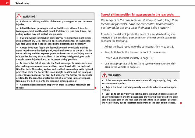
Correct sitting position for passengers in the rear seats
Passengers in the rear seats must sit up straight, keep theirfeet on the footwells, have the rear central head restraintpositioned for use and wear their seat belts properly.
To reduce the risk of injury in the event of a sudden braking ma-noeuvre or an accident, passengers on the rear bench seat mustconsider the following:
– Adjust the head restraint to the correct position ⇒ page 13.
– Keep both feet in the footwell in front of the rear seat.
– Fasten your seat belt securely ⇒ page 19.
– Use an appropriate child restraint system when you take chil-dren in the vehicle ⇒ page 43.
WARNING
● If the passengers on the rear seat are not sitting properly, they couldsustain severe injuries.
● Adjust the head restraint properly in order to achieve maximum pro-tection.
● Seat belts can only provide optimal protection when backrests are inan upright position and the passengers are wearing their seat belts prop-erly. If passengers on the rear seat are not sitting in an upright position,the risk of injury due to incorrect positioning of the seat belt increases.

13Safe driving
Correct adjustment of head restraints
Properly adjusted head restraints are an important part ofpassenger protection and can reduce the risk of injuries inmost accident situations.
Fig. 3 Properly adjustedhead restraint viewedfrom the front
Fig. 4 Properly adjustedhead restraint viewedfrom the side
Adjust the head restraint properly in order to achieve maximumprotection.
– Adjust the head restraint so that its upper edge is at the samelevel as the top of your head or as close as possible to the samelevel as the top of your head and, at the very least, at eye level⇒ fig. 3 and ⇒ fig. 4.
Adjusting the head restraints ⇒ page 114.
WARNING
● Travelling with the head restraints removed or improperly adjustedincreases the risk of severe injuries.
● Incorrectly adjusted head restraints could result in death in the eventof a collision or accident.
● Incorrectly adjusted head restraints also increase the risk of injuryduring sudden or unexpected driving or braking manoeuvres.
● The head restraints must always be adjusted according to the pas-senger's height.
Safety First Operating Instructions Practical Tips Technical Specifications

14 Safe driving
Rear head restraints
Fig. 5 Adjusting the rearhead restraints
The rear head restraints have 2 positions:
● Raised position or position for use A ⇒ fig. 5. In this position, the headrestraint is used normally, protecting the occupant of the rear seats, alongwith the rear seat belts.
● Rest position, not in use B ⇒ fig. 5. This position improves the driver'srear visibility.
To fit the head restraint in position for use A , pull on the edges with bothhands in the direction of the arrow. To place it in rest position B , lower thehead restraint.
WARNING
Whenever a passenger is seated on the rear central seat, the head re-straint should be placed in the position for use A .
NoteNote the instructions on the head restraints adjustment.
Examples of incorrect sitting positions
An incorrect sitting position can lead to severe injuries to oc-cupants.
Seat belts can provide optimal protection only when the belt websare properly positioned. Incorrect sitting positions substantially re-duce the protective function of seat belts and increase the risk ofinjury due to incorrect seat belt position. As the driver, you are re-sponsible for all vehicle occupants, especially children.
– Never allow anyone to assume an incorrect sitting position inthe vehicle while travelling ⇒ .
The following list contains examples of sitting positions that could be dan-gerous for all occupants. The list is not complete, but we would like to makeyou aware of this issue.
Therefore, whenever the vehicle is in motion:
● Never stand in the vehicle.
● Never stand on the seats.
● Never kneel on the seats.
● Never tilt your backrest far to the rear.
● Never lean against the dash panel.
● Never lie on the rear bench.
● Never sit on the front edge of a seat.
● Never sit sideways.
● Never lean out of a window.

15Safe driving
● Never put your feet out of a window.
● Never put your feet on the dash panel.
● Never put your feet on the surface of a seat.
● Do not allow anyone to travel in the footwell.
● Never travel without wearing the seat belt.
● Do not allow anyone to travel in the luggage compartment.
WARNING
● Any incorrect sitting position increases the risk of severe injuries.
● Sitting in an incorrect position exposes the occupants to severe inju-ries if airbags are triggered, by striking a passenger who has assumed anincorrect sitting position.
● Before the vehicle moves, assume the proper sitting position andmaintain it throughout the trip. Before every trip, instruct your passen-gers to sit properly and to stay in this position during the trip ⇒ page 10,Proper sitting position for occupants.
Safety First Operating Instructions Practical Tips Technical Specifications

16 Safe driving
Pedal area
Pedals
The operation of all pedals must never be impaired by ob-jects or floor mats.
– Ensure that you can always press the accelerator, brake andclutch pedals unimpaired to the floor.
– Ensure that the pedals can return unimpaired to their initial po-sitions.
Use only floor mats which leave the pedal area free and can be securely fas-tened on the footwell.
If a brake circuit fails, the brake pedal must be pressed down thoroughly inorder to stop the vehicle.
Wearing suitable shoes
Always wear shoes which support your feet properly and give you a goodfeeling for the pedals.
WARNING
● Restricting pedal operation can lead to critical situations while driv-ing.
● Never place objects on the driver footwell. An object could move intothe pedal area and impair pedal operation. In the event of a sudden driv-ing or braking manoeuvre, you will not be able to operate the brake,clutch or accelerator pedal. Risk of accident!
Floor mats on the driver side
Only floor mats may be used which can be securely fastenedin the footwell and do not impair operation of the pedals.
– Ensure that the floor mats are securely fastened during the tripand do not obstruct the pedals ⇒ .
Only use floor mats which leave the pedals clear and which are secured toprevent them from slipping. You can obtain suitable floor mats from a speci-alised dealership.
WARNING
● If the pedals are obstructed, an accident may occur. Risk of seriousinjuries.
● Ensure that the floor mats are always securely attached.
● Never lay or fit floor mats or other floor coverings over the originalfloor mats. This would reduce the pedal area and could obstruct the ped-als. Risk of accident.
Storing objects
Loading the luggage compartment
All luggage and other loose objects must be safely securedin the luggage compartment.
Unsecured objects which shift back and forth could affect safety ordriving characteristics of the vehicle by shifting the centre of gravi-ty.

17Safe driving
– Distribute the load evenly in the luggage compartment.
– Place heavy objects as far forward as possible in the luggagecompartment.
– Place the heavy objects first.
WARNING
● Loose luggage and other objects in the luggage compartment couldcause serious injuries.
● Always put objects in the luggage compartment.
● During sudden manoeuvres or accidents, loose objects can be thrownforward, injuring vehicle occupants or even third parties. This increasedrisk of injury will be further increased if a loose object is struck by an in-flating airbag. If this happens, objects can be transformed into “mis-siles”. Risk of fatal injury.
● Please note that the centre of gravity may shift when transportingheavy objects; this may affect the vehicle's handling and lead to an acci-dent. Therefore, it is essential to adjust your speed and driving style ac-cordingly, to avoid accidents.
● Never exceed the allowed axle weights or allowed maximum weight.If the allowed axle load or the allowed total weight is exceeded, the driv-ing characteristics of the vehicle may change, leading to accidents, inju-ries and damage to the vehicle.
● Never leave your vehicle unattended, especially when the tailgate isopen. Children could climb into the luggage compartment, closing thedoor behind them; they will be trapped and run the risk of death.
● Never allow children to play in or around the vehicle. Close and lockall the doors and tailgate when you leave the vehicle. Before you lock thevehicle, make sure that there are no adults or children in the vehicle.
● Never transport passengers in the luggage compartment. All passen-gers must have their seat belt fastened ⇒ page 19.
Note● Air circulation in the vehicle helps reduce fogging of the windows. Usedair escapes through ventilation slits in the side trim of the luggage compart-ment. Ensure that the ventilation slits are never covered.
Fastening rings
There can be four fastening rings in the luggage compart-ment for fastening luggage and other objects.
– Always use suitable and undamaged straps to secure luggageand other objects to the fastening rings ⇒ in Loading the lug-gage compartment on page 17.
– Pull up the fastening rings to attach the straps.
During a collision or an accident, even small and light objects can build upso much energy that they can cause very severe injuries. The amount of ki-netic energy depends on the speed of the vehicle and the weight of the ob-ject. The most significant factor, however, is the speed of the vehicle.
Example: An object weighing 4.5 kg is lying unsecured in the vehicle. Dur-ing a frontal collision at a speed of 50 km/h, this object generates a forcecorresponding to 20 times its weight. That means that the effective weightof the object increases to about 90 kg. You can imagine the severity of theinjuries which might be sustained if this object strikes an occupant as itflies through the passenger compartment. This increased risk of injury willbe further increased if a loose object is struck by an inflating airbag.
Safety First Operating Instructions Practical Tips Technical Specifications

18 Safe driving
WARNING
● If pieces of luggage or other objects are secured to the fasteningrings with inappropriate or damaged retaining cords, injuries could besustained in the event of braking manoeuvres or accidents.
● To prevent pieces of luggage or other objects from flying forward, al-ways use appropriate retaining cords which are secured to the fasteningrings.
● Never secure a child seat on the fastening rings.

19Seat belts
Seat belts
Brief introduction
Before driving: remember your seat belt!
Wearing a seat belt properly can save your life!
In this chapter you will learn the importance of wearing seat belts,how they work and how to properly fasten, adjust and wear them.
– Read and consider all the information as well as the warnings inthis chapter.
WARNING
● Before inserting the central rear seat belt into its catch, make surethat the backrest is properly engaged in position by pulling on the belt.
● If seat belts are worn incorrectly or not at all, the risk of severe inju-ries increases.
● Properly worn seat belts can reduce severe injuries in case of suddenbraking manoeuvres or accidents. For safety reasons, you and your pas-sengers must always wear the seat belts properly while the vehicle ismoving.
● Pregnant women or people with physical disabilities must also useseat belts. Like all other passengers, these people can also sustain se-vere injuries if they are not wearing their seat belts properly.
Number of seats
Your vehicle has five seats, two in the front and three in the rear. Each seatis equipped with a three-point seat belt.
In some versions, your vehicle is approved only for four seats. Two frontseats and two rear seats.
WARNING
● More people than available seats must never be transported in yourvehicle.
● Every passenger in the vehicle must properly fasten and wear theseat belt belonging to his or her seat. Children must be protected with anappropriate child restraint system.
Safety First Operating Instructions Practical Tips Technical Specifications

20 Seat belts
Seat belt warning lamp*
The warning lamp acts as a reminder to the driver to fastenthe seat belt.
Before starting the vehicle:
– Fasten your seat belt securely.
– Instruct your passengers to fasten their seat belts properly be-fore driving off.
– Protect children by using a child seat according to the child'sheight and weight.
The warning lamp in the instrument panel lights up1) if the driver or pas-senger seat belt is not fastened1) when the ignition is switched on. More-over, an acoustic signal1) is heard on exceeding 25 km/h. This acoustic sig-nal stops when the seat belt is fastened.
The warning lamp* is switched off if the driver seat belt is fastened whilethe ignition is switched on.
1) Depending on the model version

21Seat belts
Why wear seat belts?
Physical principles of frontal collisions
In the event of a frontal collision, a large amount of kineticenergy must be absorbed.
Fig. 6 Vehicle about tohit a wall: the occupantsare not wearing seatbelts
Fig. 7 The vehicle hitsthe wall: the occupantsare not wearing seatbelts
It is easy to explain how the laws of physics work in the case of a head-oncollision: When a vehicle starts moving ⇒ fig. 6, a certain amount of energyknown as kinetic energy is produced in the vehicle and its occupants.
The amount of kinetic energy depends on the speed of the vehicle and theweight of the vehicle and its passengers. The higher the speed and thegreater the weight, the more energy there is to be released in an accident.
The most significant factor, however, is the speed of the vehicle. If thespeed doubles from 25 km/h to 50 km/h, for example, the kinetic energy ismultiplied by four.
Because the passengers in our example are not restrained by seat belts, inthe case of a head-on collision all of their kinetic energy has to be absorbedat the point of impact ⇒ fig. 7.
Even at speeds of 30 km/h to 50 km/h, the forces acting on bodies in a col-lision can easily exceed one tonne (1000 kg). At greater speed these forcesare even higher.
Passengers not wearing seat belts are not “attached” to the vehicle. In ahead-on collision, they will move forward at the same speed their vehicle
Safety First Operating Instructions Practical Tips Technical Specifications

22 Seat belts
was travelling just before the impact. This example applies not only tohead-on collisions, but to all accidents and collisions.
The danger of not using the seat belt
The general belief that the passengers can protect them-selves with their hands in a minor collision is false.
Fig. 8 A driver not wear-ing a seat belt is thrownforward violently.
Fig. 9 The unbelted rearpassenger is thrown for-ward violently, hitting thedriver wearing a seatbelt.
Even at low speeds the forces acting on the body in a collision are so greatthat it is not possible to brace oneself with one's hands. In a frontal colli-sion, unbelted passengers are thrown forward and will make violent contactwith the steering wheel, dash panel, windscreen or whatever else is in theway ⇒ fig. 8.
The airbag system is not a substitute for seat belts. When triggered, airbagsprovide only additional protection. All occupants (including the driver) mustwear seat belts properly during the trip. This will reduce the risk of severeinjuries in the event of an accident – regardless of whether an airbag is fit-ted for the seat or not.
Note that airbags can be triggered only once. To achieve the best possibleprotection, the seat belt must always be worn properly so that you will beprotected in accidents in which no airbag is deployed.
It is also important for the rear passengers to wear seat belts properly, asthey could otherwise be thrown forward violently in an accident. Rear pas-sengers who do not use seat belts endanger not only themselves but alsothe front occupants ⇒ fig. 9.

23Seat belts
Seat belt protection
Passengers not wearing seat belts risk severe injuries in theevent of an accident.
Fig. 10 A driver wearingthe seat belt properly issecured by the belt insharp braking
Properly worn seat belts hold the vehicle occupants in the correct sitting po-sitions and substantially reduce the kinetic energy in the event of an acci-dent. Seat belts also help to prevent uncontrolled movements that couldlead to severe injuries. In addition, properly worn seat belts reduce the dan-ger of being thrown from the vehicle.
Passengers wearing their seat belts correctly benefit greatly from the abilityof the belts to absorb kinetic energy. The front part of your vehicle and otherpassive safety features (such as the airbag system) are also designed to ab-sorb the kinetic energy released in a collision. Taken together, all these fea-tures reduce the releasing kinetic energy and consequently, the risk of in-jury.
Our examples describe frontal collisions. Of course, properly worn seat beltssubstantially reduce the risk of injury in all other types of accidents. This iswhy it is so important to fasten seat belts before every trip, even when "justdriving around the corner".
Ensure that your passengers wear their seat belts as well. Accident statisticshave shown that wearing seat belts is an effective means of substantiallyreducing the risk of injury and improving the chances of survival in a seri-ous accident. Furthermore, properly worn seat belts improve the protectionprovided by airbags in the event of an accident. For this reason, wearing aseat belt is required by law in most countries.
Although your vehicle is equipped with airbags, the seat belts must be fas-tened and worn. The front airbags, for example, are only triggered in somefrontal accidents. The front airbags will not be triggered during minor frontalcollisions, minor side collisions, rear collisions, overturns or accidents inwhich the airbag trigger threshold value in the control unit is not exceeded.
Therefore, you should always wear your seat belt and ensure that your pas-sengers have fastened their seat belts properly before you drive off!
Safety instructions on using seat belts
If seat belts are used correctly, they can reduce the risk of in-jury in an accident.
– Always wear the seat belt as described in this section.
– Ensure that the seat belts can be fastened at all times and arenot damaged.
Safety First Operating Instructions Practical Tips Technical Specifications

24 Seat belts
WARNING
● If the seat belts are worn incorrectly or not at all, the risk of severeinjuries increases. The optimal protection from seat belts can be ach-ieved only if you use them properly.
● Fasten your seat belt before every trip - even when driving in town.The other passengers must also wear the seat belts at all times, other-wise they run the risk of being injured.
● The seat belt cannot offer its full protection if the seat belt is notpositioned correctly.
● Never allow two passengers (even children) to share the same seatbelt.
● Keep both feet in the footwell in front of your seat as long as the vehi-cle is in motion.
● Never unbuckle a seat belt while the vehicle is in motion. Risk of fatalinjury.
● The seat belt must never be twisted while it is being worn.
● The seat belt should never lie on hard or fragile objects (such asglasses or pens, etc.) because this can cause injuries.
● Do not allow the seat belt to be damaged or jammed, or to rub on anysharp edges.
● Never wear the seat belt under the arm or in any other incorrect posi-tion.
● Loose, bulky clothing (such as an overcoat over a jacket) impairs theproper fit and function of the belts, reducing their capacity to protect.
● The slot in the seat belt buckle must not be blocked with paper orother objects, as this can prevent the latch plate from engaging securely.
● Never use seat belt clips, retaining rings or similar instruments to al-ter the position of the belt webbing.
WARNING (Continued)
● Frayed or torn seat belts or damage to the connections, belt retrac-tors or parts of the buckle could cause severe injuries in the event of anaccident. Therefore, you must check the condition of all seat belts at reg-ular intervals.
● Seat belts which have been worn in an accident and stretched mustbe replaced by a specialised workshop. Renewal may be necessary evenif there is no apparent damage. The belt anchorage should also bechecked.
● Do not attempt to repair a damaged seat belt yourself. The seat beltsmust not be removed or modified in any way.
● The belts must be kept clean, otherwise the retractors may not workproperly.

25Seat belts
Seat belts
Seat belt adjustment
The seat belts for the front and rear occupants are locked in-to position by a latch.
Fig. 11 Belt buckle andlatch plate of seat belt
The seat belt cannot offer its full protection if the seat belt is notpositioned correctly.
– Adjust the seat and head restraint correctly.
– To fasten the belt, take hold of the latch plate and pull it slowlyacross your chest and lap.
– Insert the latch plate into the buckle for the appropriate seatand push it down until it is securely locked with an audible click⇒ fig. 11.
– Pull the belt to ensure that the latch plate is securely engagedin the buckle.
The seat belts are equipped with an automatic retractor on the shoulderstrap. Full freedom of movement is permitted when the shoulder belt ispulled slowly. However, during sudden braking, during travel in steep areasor bends and during acceleration, the automatic retractor on the shoulderbelt is locked.
The automatic belt retractors on the front seats are fitted with seat belt ten-sioners ⇒ page 28.
WARNING
● An incorrectly worn seat belt can cause severe injuries in the event ofan accident.
● The seat belts offer best protection only when the backrests are in anupright position and the seat belts have been fastened properly.
● Never put the latch plate in the buckle of another seat. If you do this,the seat belt will not protect you properly and the risk of injury is in-creased.
● If an occupant is incorrectly belted in, the belt cannot protect him orher properly. An incorrectly positioned seat belt can cause extremely se-vere injuries.
Safety First Operating Instructions Practical Tips Technical Specifications

26 Seat belts
Seat belt position
Seat belts offer their maximum protection only when theyare properly positioned.
Fig. 12 Correct seat beltand head restraint posi-tions, viewed from front
Fig. 13 Correct seat beltand head restraint posi-tions, viewed from side
WARNING
● An incorrectly worn seat belt can cause severe injuries in the event ofan accident.
● The shoulder belt must be positioned around the middle of the shoul-der. The seat belt must lie flat and snugly on the torso ⇒ fig. 12.
● The lap part of the seat belt must lie across the pelvis, never acrossthe stomach. The seat belt must lie flat and snugly on the pelvis⇒ fig. 13. Pull the belt tight if necessary to take up any slack.
● Read and observe the warnings ⇒ page 23.
Pregnant women must also fasten their seat belts properly
The best protection for the unborn child is for the mother towear the seat belt properly at all times during the pregnan-cy.
Fig. 14 Positioning seatbelts during pregnancy

27Seat belts
The seat belt provides maximum protection only when the seat beltis properly positioned ⇒ page 26.
– Adjust the front seat and head restraint correctly.
– Holding the latch plate, pull the belt evenly across your chestand as low as possible over the pelvis ⇒ fig. 14.
– Insert the latch plate into the buckle for the corresponding seatand push it down until it is securely locked with an audible click⇒ .
– Pull the belt to ensure that the latch plate is securely engagedin the buckle.
WARNING
● An incorrectly worn seat belt can cause severe injuries in the event ofan accident.
● For pregnant women, the lap part of the seat belt must lie as low aspossible over the pelvis, never across the stomach, and always lie flat sothat no pressure is exerted on the abdomen.
● Read and observe the warnings ⇒ page 23.
Seat belt release
The seat belt must not be unfastened until the vehicle hascome to a standstill.
Fig. 15 Removing latchplate from buckle
– Press the red button on the belt buckle ⇒ fig. 15. The latch plateis released and springs out ⇒ .
– Guide the belt back by hand so that it rolls up easily and thetrim is not damaged
WARNING
Never unbuckle a seat belt while the vehicle is in motion. If you do, youincrease the risk of sustaining severe or fatal injuries.
Safety First Operating Instructions Practical Tips Technical Specifications

28 Seat belts
Incorrectly fastened seat belts
Incorrectly worn seat belts can cause severe or even mortalinjuries.
Seat belts can provide optimal protection only if the belt web isproperly worn. The seat belts must be fastened exactly in the orderdescribed in this chapter. An incorrect sitting position impairs sub-stantially the protection a seat belt offers and can lead to severe orfatal injuries. The risk of severe or fatal injuries is especially in-creased when a deploying airbag strikes an occupant who has as-sumed an incorrect sitting position. As the driver, you are responsi-ble for all vehicle occupants, especially children. Therefore:
– Never allow anyone to wear the seat belt incorrectly while thevehicle is moving ⇒ .
WARNING
● An incorrectly worn seat belt increases the risk of severe injuries.
● Before every trip, instruct your passengers to adjust their seat beltsproperly and to wear them for the whole journey.
● Read and always observe information and warnings concerning theuse of seat belts ⇒ page 23.
Belt tensioners*
Function of the seat belt tensioner
During a frontal collision, the seat belts on the front seatsare retracted automatically.
The seat belts for the front occupants are equipped with belt tensioners.Sensors will trigger the belt tensioners during severe head-on, lateral andrear collisions only if the seat belt is being worn. This retracts and tightensthe seat belts, reducing the forward motion of the occupants.
The seat belt tensioner can be triggered only once.
The belt tensioners will not be triggered in the event of light frontal and sidecollisions, if the vehicle overturns, or in situations where no large forces acton the front, side or rear of the vehicle.
Note● If the seat belt tensioners are triggered, a fine dust is produced. This isnormal and it is not an indication of fire in the vehicle.
● The relevant safety requirements must be observed when the vehicle orcomponents of the system are scrapped. Specialised workshops are famili-ar with these regulations, which are also available to you.
Service and disposal of belt tensioners
The belt tensioners are components of the seat belts that are installed inthe seats of your vehicle. If you work on the belt tensioners or remove andinstall parts of the system when performing other repair work, the seat beltmay be damaged. The consequence may be that, in the event of an acci-dent, the belt tensioners function incorrectly or not at all.

29Seat belts
So that the effectiveness of the seat belt tensioner is not reduced and thatremoved parts do not cause any injuries or environmental pollution, regula-tions, which are known to the specialised workshops, must be observed.
WARNING
● Improper use or repairs not carried out by qualified mechanics in-crease the risk of severe or fatal injuries. The belt tensioners may fail totrigger or may trigger in the wrong circumstances.
● Never attempt to repair, adjust, remove or install parts of the belt ten-sioners or seat belts.
● The seat belt tensioner, seat belt and automatic retractor cannot berepaired.
● Any work on the belt tensioners and seat belts, including the removaland refitting of system parts in conjunction with other repair work, mustbe performed by a specialised workshop only.
● The belt tensioners will only provide protection for one accident andmust be changed if they have been activated.
Safety First Operating Instructions Practical Tips Technical Specifications

30 Airbag system
Airbag system
Brief introduction
Why wear a seat belt and assume the correct sittingposition?
For the inflating airbags to achieve the best protection, theseat belt must always be worn properly and the correct sit-ting position must be assumed.
For your own safety and the safety of the passengers, please en-sure the following before driving:
– Always wear the seat belt properly
– Adjust the driver seat and the steering wheel correctly.
– Adjust the front passenger seat correctly.
– Adjust the head restraint correctly ⇒ page 13.
– Use an appropriate child restraint system to protect children inyour vehicle.
The airbag is deployed at high speed in fractions of a second. If you have anincorrect seating position at the time the airbag is deployed, it could causeyou critical injuries. Therefore, it is essential that all passengers in the vehi-cle assume a correct sitting position while travelling.
A sharp braking before an accident may cause a passenger not wearing aseat belt to be thrown forward into the area of the deploying airbag. In thiscase, the inflating airbag may inflict critical or fatal injuries on the occupant.This also applies to children.
Always maintain the greatest possible distance between yourself and thefront airbag. This way, the front airbags can completely deploy when trig-gered, providing their maximum protection.
The most important factors that will trigger an airbag are: the type of acci-dent, the angle of collision and the speed of the vehicle.
Whether the airbags are triggered depends primarily on the vehicle deceler-ation rate resulting from the collision and detected by the control unit. If thevehicle deceleration occurring during the collision and measured by thecontrol unit remains below the specified reference values, the front, sideand/or curtain airbag will not be triggered. Take into account that the visibledamage in a vehicle involved in an accident, no matter how serious, is not adetermining factor for the airbags to have been triggered.
WARNING
● Wearing the seat belt incorrectly or assuming an incorrect sitting po-sition can lead to critical or fatal injuries.
● All occupants, including children, who are not properly belted cansustain critical or fatal injuries if the airbag is triggered. Children up to12 years old should always travel on the rear seat. Never transport chil-dren in the vehicle if they are not restrained or the restraint system is notappropriate for their age, size or weight.
● If you are not wearing a seat belt, if you lean forward or to the sidewhile travelling or assume an incorrect sitting position, there is a sub-stantially increased risk of injury. This increased risk of injury will be fur-ther increased if you are struck by an inflating airbag.
● To reduce the risk of injury from an inflating airbag, always wear theseat belt properly.
● Always adjust the front seats properly.
31Airbag system
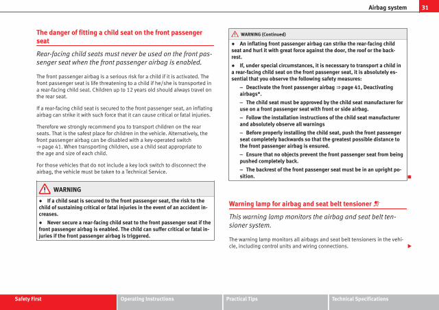
The danger of fitting a child seat on the front passengerseat
Rear-facing child seats must never be used on the front pas-senger seat when the front passenger airbag is enabled.
The front passenger airbag is a serious risk for a child if it is activated. Thefront passenger seat is life threatening to a child if he/she is transported ina rear-facing child seat. Children up to 12 years old should always travel onthe rear seat.
If a rear-facing child seat is secured to the front passenger seat, an inflatingairbag can strike it with such force that it can cause critical or fatal injuries.
Therefore we strongly recommend you to transport children on the rearseats. That is the safest place for children in the vehicle. Alternatively, thefront passenger airbag can be disabled with a key-operated switch⇒ page 41. When transporting children, use a child seat appropriate tothe age and size of each child.
For those vehicles that do not include a key lock switch to disconnect theairbag, the vehicle must be taken to a Technical Service.
WARNING
● If a child seat is secured to the front passenger seat, the risk to thechild of sustaining critical or fatal injuries in the event of an accident in-creases.
● Never secure a rear-facing child seat to the front passenger seat if thefront passenger airbag is enabled. The child can suffer critical or fatal in-juries if the front passenger airbag is triggered.
WARNING (Continued)
● An inflating front passenger airbag can strike the rear-facing childseat and hurl it with great force against the door, the roof or the back-rest.
● If, under special circumstances, it is necessary to transport a child ina rear-facing child seat on the front passenger seat, it is absolutely es-sential that you observe the following safety measures:
– Deactivate the front passenger airbag ⇒ page 41, Deactivatingairbags*.
– The child seat must be approved by the child seat manufacturer foruse on a front passenger seat with front or side airbag.
– Follow the installation instructions of the child seat manufacturerand absolutely observe all warnings
– Before properly installing the child seat, push the front passengerseat completely backwards so that the greatest possible distance tothe front passenger airbag is ensured.
– Ensure that no objects prevent the front passenger seat from beingpushed completely back.
– The backrest of the front passenger seat must be in an upright po-sition.
Warning lamp for airbag and seat belt tensioner
This warning lamp monitors the airbag and seat belt ten-sioner system.
The warning lamp monitors all airbags and seat belt tensioners in the vehi-cle, including control units and wiring connections.
Safety First Operating Instructions Practical Tips Technical Specifications

32 Airbag system
Monitoring of airbag and belt tensioner system
Both the airbag and belt tensioner systems operation is constantly moni-tored electronically. The warning lamp will light up for a few seconds ev-ery time the ignition is switched on (self-diagnosis).
The system must be checked when the warning lamp :
● does not light up when the ignition is switched on,
● after the ignition is switched on, it turns off after 4 seconds,
● turns off and then lights up again after the ignition is switched on,
● lights up or flashes while the vehicle is moving.
In the event of a malfunction, the warning lamp remains on continuously.Have the airbag system inspected immediately by a qualified workshop.
If any of the airbags are de-activated by the Authorised Service Centre, theindicator lights for several seconds more after the verification and will turnoff if there is no fault.
WARNING
● If there is a malfunction, the airbag and belt tensioner system cannotproperly perform its protective function.
● If a malfunction occurred, have the system checked immediately by aspecialised workshop. Otherwise, in the event of an accident, the airbagsystem and belt tensioners may not be triggered, or may not be triggeredcorrectly.
Repairs, maintenance and disposal of airbags
The parts of the airbag system are installed in various places in your vehi-cle. If work is carried out on the airbag system or parts have to be removedand fitted on the system when performing other repair work, parts of the air-
bag system may be damaged. In the event of an accident this could causethe airbag to inflate incorrectly or not inflate at all.
The relevant safety requirements must be observed when the vehicle orcomponents of the airbag are scrapped. Specialised workshops and vehicledisposal centres are familiar with these requirements.
WARNING
● If repairs are not carried out by a professional, or if the airbags areused incorrectly, the risk of severe or fatal injuries is increased. The air-bags may fail to inflate, or could inflate in the wrong circumstances.
● Do not cover or stick anything on the steering wheel hub or the sur-face of the airbag unit on the passenger side of the dash panel, and donot obstruct or modify them in any way.
● It is important not to attach any objects such as cup holders or tele-phone mountings to the surfaces covering the airbag units.
● To clean the steering wheel or dash panel, you may use only a dry or awater-moistened cloth. Never clean the dash panel and the airbag mod-ule surface with cleaners containing solvents. Solvents cause the surfaceto become porous. If the airbag triggered, plastic parts could become de-tached and cause injuries.
● Never attempt to repair, adjust, remove or install parts of the airbagsystem.
● Any work on the airbag system or removal and installation of the air-bag components for other repairs (such as repairs to the steering wheel)should be performed only by a specialised workshop. Specialised work-shops have the necessary tools, repair information and qualified person-nel.
● We strongly recommend you to go to a specialised workshop for allwork on the airbag system.
● Never attempt to alter the front bumper or the body.
● The airbags provide protection for just one accident; replace themonce they have deployed.

33Airbag system
For the sake of the environmentThe airbags, which are a special type of waste, must be disposed of throughan authorised service, because they contain pyrotechnic elements.
Safety First Operating Instructions Practical Tips Technical Specifications

34 Airbag system
Front airbags
Description of front airbags
The airbag system is not a substitute for the seat belts.
Fig. 16 Driver airbag lo-cated in steering wheel
Fig. 17 Front passengerairbag located in dashpanel
The front airbag for the driver is located in the steering wheel ⇒ fig. 16 andthe airbag for the front passenger is located in the dash panel ⇒ fig. 17. Air-bags are identified by the word “AIRBAG”.
In conjunction with the seat belts, the front airbag system gives the frontoccupants additional protection for the head and chest in the event of a se-vere frontal collision ⇒ page 37, Safety notes on the front airbag system.
In addition to their normal function of restraining the occupants, the seatbelts also hold the driver and front passenger in a position where the air-bags can provide maximum protection in a frontal collision.
The airbag system is not a substitute for seat belts, but it is an integral partof the vehicle's overall passive safety system. Please bear in mind that theairbag system can only work effectively when the occupants are wearingtheir seat belts correctly and have adjusted the head restraints properly. Forthis reason, it is most important to wear the seat belts at all times, not onlybecause this is required by law in most countries, but also as a contributionto your own safety
The main parts of the front airbag system are:
● an electronic control and monitoring system (control unit)
● the two front airbags (airbag with gas generator) for the driver and frontpassenger,
● a warning lamp on the instrument panel ⇒ page 31
The airbag system operation is monitored electronically. The airbag warninglamp will light up for a few seconds every time the ignition is switched on(self-diagnosis).
There is a fault in the system if the warning lamp :
● does not light up when the ignition is switched on ⇒ page 31
● after the ignition is switched on, it turns off after 4 seconds,
● turns off and then lights up again after the ignition is switched on,
● lights up or flashes while the vehicle is moving.

35Airbag system
The front airbag system will not be triggered if:
● the ignition is switched off
● there is a minor frontal collision,
● there is a side collision,
● there is a rear-end collision
● the vehicle turns over
WARNING
● The seat belts and airbags can only provide maximum protection ifthe occupants are seated correctly ⇒ page 10, Proper sitting position foroccupants.
● If a fault has occurred in the airbag system, have the system checkedimmediately by a specialised workshop. Otherwise, during a frontal colli-sion the system may fail to trigger, or not trigger correctly.
Operation of front airbags
Inflated airbags reduce the risk of head or chest injury.
Fig. 18 Inflated front air-bags
The airbag system is designed so that the airbags for the driver and frontpassenger are triggered in a severe frontal collision.
In certain types of accident the front and side airbags may be triggered to-gether.
When the system is triggered, the airbags fill with a propellant gas and de-ploy in front of the driver and front passenger ⇒ fig. 18. The fully deployedairbags cushion the forward movement of the front occupants and help toreduce the risk of injury to the head and the upper part of the body.
The special design of the airbag allows the controlled escape of the propel-lant gas when an occupant puts pressure on the bag. Thus, the head andchest are surrounded and protected by the airbag. After the collision, theairbag deflates sufficiently to allow visibility.
The airbags deploy extremely rapidly, within thousandths of a second, toprovide additional protection in the event of an accident. A fine dust may
Safety First Operating Instructions Practical Tips Technical Specifications

36 Airbag system
develop when the airbag deploys. This is normal and it is not an indicationof fire in the vehicle.
Airbag covers when the frontal airbags are triggered
Fig. 19 Airbag covers reacting when the front airbagsare triggered
The airbag covers fold out of the steering wheel or dash panel when thedriver and front passenger airbags are triggered ⇒ fig. 19. The airbag coversremain connected to the steering wheel or the dash panel.

37Airbag system
Safety notes on the front airbag system
If you use airbags correctly, they can considerably reducethe risk of injury in many kinds of accident.
WARNING
● It is important for the driver and front passenger to keep a distance ofat least 25 cm from the steering wheel and dash panel. If the minimumdistance is not observed, the airbags do not correctly protect the vehicleoccupants; risk of fatal injuries! In addition, the front seats and head re-straints must always be positioned correctly for the height of the occu-pant.
● If you are not wearing a seat belt, if you lean forward or to the sidewhile travelling or assume an incorrect sitting position, there is a sub-stantially increased risk of injury. This increased risk of injury will be fur-ther increased if you are struck by an inflating airbag.
● Never let a child travel on the front seat without an appropriate re-straint system. If the airbag is triggered in an accident, children can sus-tain serious or fatal injuries from the airbag as it inflates ⇒ page 43,Child safety.
● The deployment space between the front passengers and the airbagsmust not in any case be occupied by other passenger, pets and objects.
● The airbags provide protection for just one accident; replace themonce they have deployed.
● It is also important not to attach any objects such as cup holders ortelephone mountings to the surfaces covering the airbag units.
● Do not attempt to modify components of the airbag system in anyway.
Safety First Operating Instructions Practical Tips Technical Specifications

38 Airbag system
Side airbags
Description of side airbags
The airbag system is not a substitute for the seat belts.
Fig. 20 Side airbag indriver seat
The side airbags are located in the driver seat and front passenger seatbackrests ⇒ fig. 20. The locations are identified by the text “AIRBAG” in theupper region of the backrests.
Together with the seat belts, the side airbag system gives the front seat oc-cupants additional protection for the upper body in the event of a severeside collision ⇒ page 39, Safety notes on the operation of the side airbagsystem.
In a side collision, the side airbags reduce the risk of injury to passengerson the front seats to the areas of the body facing the impact. In addition totheir normal function of protecting the occupants in a collision, the seatbelts also hold the passengers on the front seats in a position where theside airbags can provide maximum protection.
The airbag system is not a substitute for seat belts, but it is an integral partof the vehicle's overall passive safety system. Please bear in mind that theairbag system can only work effectively when the occupants are wearingtheir seat belts. For this reason, it is most important to wear the seat beltsat all times, not only because this is required by law in most countries, butalso as a contribution to your own safety
The side airbag system will not be triggered if:
● the ignition is switched off
● there is a minor side collision
● there is a frontal collision
● there is a rear-end collision
● the vehicle turns over
The main parts of the airbag system are:
● an electronic control and monitoring system (control unit)
● the side airbags in the sides of the backrests of the front seats,
● a warning lamp on the instrument panel ⇒ page 31
The airbag system operation is monitored electronically. The airbag warninglamp will light up for approx. 4 seconds every time the ignition is switchedon (self-diagnosis).
WARNING
● Never drive the vehicle if the interior panels have been removed.
● Never drive if the interior door panels have been removed or if thepanels have not been correctly fitted.
● Never drive the vehicle if the loudspeakers in the door panels havebeen removed, unless the holes left by the loudspeakers have been cor-rectly closed.

39Airbag system
WARNING (Continued)
● Always check that the openings are closed or covered if loudspeakersor other equipment are fitted in the interior door panels.
● Any work carried out to the doors should be made in a specialisedworkshop.
● The seat belts and airbags can only provide maximum protection ifthe occupants are seated correctly ⇒ page 10, Proper sitting position foroccupants.
● If a fault has occurred in the airbag system, have the system checkedimmediately by a specialised workshop. Otherwise, during a side colli-sion, the system may fail to trigger, or not trigger correctly.
Operation of side airbags
Inflated airbags can reduce the risk of head or chest injuryin a side impact collision.
In some side collisions the side airbag is triggered on the impact side of thevehicle.
In certain types of accident the front and side airbags may be triggered to-gether.
When the system is triggered, the airbag is filled with propellant gas.
The airbags deploy extremely rapidly, within thousandths of a second, toprovide additional protection in the event of an accident. A fine dust maydevelop when the airbag deploys. This is normal and it is not an indicationof fire in the vehicle.
The fully deployed airbags cushion the movement of the occupants of thefront seats and help to reduce the risk of injury to the upper body.
The special design of the airbag allows the controlled escape of the propel-lant gas when an occupant puts pressure on the bag. Thus, the head andchest are surrounded and protected by the airbag.
Safety notes on the operation of the side airbag system
If airbags are used correctly, they can considerably reducethe risk of injury in side impact collisions.
WARNING
● If you do not wear a seat belt, if you lean forward, or are not seatedcorrectly while the vehicle is in motion, you are at a greater risk of injuryif the side airbag system is triggered in an accident.
● In order for the side airbags to provide their maximum protection, theprescribed sitting position must always be maintained with seat beltsfastened while travelling.
● Occupants of the outer seats must never carry any objects or pets inthe deployment space between them and the airbags, or allow childrenor other passengers to travel in this position. It is also important not toattach any accessories (such as cup holders) to the doors. This would im-pair the protection offered by the side airbags.
● The built-in coat hooks should be used only for lightweight clothing.Do not leave any heavy or sharp-edged objects in the pockets.
● Great forces, such as hard blows or kicks, must not be exerted uponthe backrest bolster because the system may be damaged. In this case,the side airbags would not be triggered.
Safety First Operating Instructions Practical Tips Technical Specifications

40 Airbag system
WARNING (Continued)
● Under no circumstances should protective covers be fitted over seatswith side airbags unless the covers have been approved for use in yourvehicle. Because the airbag deploys from the side of the backrest, theuse of conventional seat covers would obstruct the side airbag, seriouslyreducing the airbag's effectiveness.
● Any damage to the original seat upholstery or around the seams ofthe side airbag units must be repaired immediately by a specialisedworkshop.
● The airbags provide protection for just one accident; replace themonce they have deployed.
● When children assume an incorrect sitting position, they exposethemselves to an increased risk of injury in the event of an accident. Thisis particularly the case if the child is travelling on the front passengerseat and the airbag system is triggered in an accident; this could havecritical consequences including serious injury or death ⇒ page 43,Child safety.
● Any work on the side airbag system or removal and installation of theairbag components for other repairs (such as removal of the front seat)should only be performed by a specialised workshop. Otherwise, faultsmay occur during the airbag system operation.
● Do not attempt to modify components of the airbag system in anyway.
● To ensure the correct functioning of the side and head airbags neitherthe doors nor the door panels should be modified in any way (e.g. fittingloudspeakers). If the front door is damaged, the airbag system may notwork correctly. All work carried out on the front door must be made in aspecialised workshop.

41Airbag system
Deactivating airbags*
Front passenger airbag deactivation
If you fit a rear-facing child seat to the front passenger seat,the front passenger airbag must be de-activated.
Fig. 21 In the glove com-partment: switch for acti-vating and deactivatingthe front passenger air-bag
Fig. 22 Warning lamp fordeactivated passengerairbag in centre console
When the passenger airbag is deactivated, this means that onlythe passenger front airbag is deactivated. All the other airbags inthe vehicle remain activated.
Deactivating the front passenger airbag
– Switch the ignition off.
– Turn the ignition switch in the key operated switch in the glovecompartment to the position OFF ⇒ fig. 21.
– Check that the warning lamp “AIRBAG OFF” on the dash panel⇒ fig. 22 remains lit ⇒ when the ignition is switched on.
Activating the front passenger airbag
– Switch the ignition off.
– Turn the ignition key in the key-operated switch in the glovecompartment to the position ON ⇒ fig. 21.
Safety First Operating Instructions Practical Tips Technical Specifications

42 Airbag system
– Check that the warning lamp “AIRBAG OFF” in the console does⇒ fig. 22 not light up when the ignition is switched on ⇒ .
WARNING
● The driver is responsible for the proper position of the key-operatedswitch.
● You should only deactivate the front passenger airbag when, in ex-ceptional cases, you have to use a rear-facing child seat on the front pas-senger seat ⇒ page 43, Child safety.
● Never install a child seat facing backwards on the front passengerseat unless the front passenger airbag has been disabled. Otherwise,there is a risk of death. If under exceptional circumstances it is necessaryto transport a child in a rear-facing child seat on the front passengerseat, you must always disable the front passenger airbag.
● As soon as the child seat is no longer needed on the front passengerseat, enable the front passenger airbag again.
● Only deactivate the passenger airbag when the ignition is off, other-wise a fault may occur in the airbag system, which could cause the airbagto not deploy properly or not deploy at all.
● When the passenger airbag is deactivated, if the warning lamp AIR-BAG OFF is not continuously lit up when the front passenger airbag is dis-abled, there may be a fault in the airbag system:
– Have the airbag system inspected immediately by a specialisedworkshop.
– Do not use a child seat on the front passenger seat! The front pas-senger airbag could be triggered despite the fact that there is a faultin the system and, as a result, a child could sustain serious or fatalinjuries.
– It is unpredictable whether the front passenger airbag will deployin the event of an accident. Warn all your passengers of this.

43Child safety
Child safety
Brief introduction
Introduction
Statistics show that children are generally safer on the rearseat than on the front passenger seat.
For safety reasons we recommend that children under 12 years of age travelon the rear seats. Depending on their age, height and weight, children trav-elling on the rear seat must use a child seat or a seat belt. For safety rea-sons, the child seat should be installed in the centre of the rear seat or be-hind the front passenger seat.
The physical laws involved and the forces acting in a collision apply also tochildren. ⇒ page 21, Why wear seat belts?. But unlike adults, children donot have muscle and bone structures fully developed. This means that chil-dren are subject to a greater risk of injury.
To reduce this risk, children must always use special child restraint systemswhen travelling in the vehicle.
We recommend the use of child safety products from the SEAT Genuine Ac-cessories Programme, which includes systems for all ages made by Peke1).
These systems have been especially designed and approved, complyingwith the ECE-R44. regulation.
Follow the manufacturer's instructions and observe any statutory require-ments when installing and using child seats. Always read and note⇒ page 43, Safety notes on using child seats.
We recommend you to include the manufacturer's Child Seat instructionmanual together with the on-board documentation.
Safety notes on using child seats
Proper use of child seats substantially reduces the risk of in-jury in an accident!
As the driver, you are responsible for any children you transport inyour vehicle.
– Protect your children by properly using the appropriate childseats ⇒ page 45.
– Always ensure that the seat belt is properly positioned accord-ing to the instructions provided by the manufacturer of the childseat.
– When travelling, do not allow children to distract you from traf-fic.
– Take breaks regularly during long trips. Take a break at least ev-ery two hours.
1) Not for all countries
Safety First Operating Instructions Practical Tips Technical Specifications

44 Child safety
WARNING
● Never install a child seat facing backwards on the front passengerseat unless the front passenger airbag has been disabled. This couldlead to a risk of potentially fatal injuries to the child! However, if it is nec-essary, in exceptional cases, to transport a child in the front passengerseat, the front passenger airbag must always be disabled ⇒ page 41, De-activating airbags*. If the passenger seat has a height adjustment op-tion, move it to the highest position.
● For those vehicles that do not include a key lock switch to disconnectthe airbag, the vehicle must be taken to a Technical Service.
● All passengers, especially children, must assume the proper sittingposition and be properly belted in while travelling.
● Never hold children or babies on your lap, this can result in potential-ly fatal injuries to the child!
● Never allow a child to be transported in a vehicle without being prop-erly secured, or to stand up or kneel on a seat while travelling. In an acci-dent, the child could be flung through the vehicle, causing possibly fatalinjuries to themselves and to the other passengers.
● If children assume an improper sitting position when the vehicle ismoving, they expose themselves to greater risk of injury in the event of asudden braking manoeuvre or in an accident. This is particularly impor-tant if the child is travelling on the front passenger seat and the airbagsystem is triggered in an accident; as this could cause serious injury oreven death.
● A suitable child seat can protect your child!
● Never leave an unsupervised child alone on a child seat or in the vehi-cle.
● Depending on weather conditions, it may become extremely hot orcold inside the vehicle. This can be fatal.
WARNING (Continued)
● Children who are less than 1.5 metres tall must not wear a normalseat belt without a child seat, as this could cause injuries to the abdomi-nal and neck areas during a sudden braking manoeuvre or in an accident.
● Do not allow the seat belt to become twisted or jammed, or to rub onany sharp edges.
● Incorrectly worn seat belts can cause injuries even in a minor colli-sion or in sudden braking manoeuvres.
● The seat belt provides maximum protection only when the seat belt isproperly positioned ⇒ page 25, Seat belts.
● Only one child may occupy a child seat ⇒ page 45, Child seats.

45Child safety
Child seats
Categorisation of child seats into groups
Use only child seats that are officially approved and suitablefor the child.
Child seats are subject to the regulation ECE-R 44. ECE-R stands for: Eco-nomic Commission for Europe Regulation
The child seats are grouped into 5 categories:
Group 0: up to 10 kg
Group 0+: up to 13 kg
Group 1: from 9 to 18 kg
Group 2: from 15 to 25 kg
Group 3: from 22 to 36 kg
Child seats that have been tested and approved under the ECE R44 stand-ard bear the test mark on the seat (the letter E in a circle with the test num-ber below it).
Group 0 and 0+ child seats
A suitable child seat and a correctly adjusted seat belt canhelp you to protect your child.
Fig. 23 A group 0 rear-facing child seat fitted onthe rear seat.
Group 0: For babies from about 9 months old and 10 kg in weight, the mostsuitable seats are those appearing in the illustration ⇒ fig. 23.
Group 0+: For babies from about 18 months old and 13 kg in weight, themost suitable seats are those appearing in the figure ⇒ fig. 23.
Follow the manufacturer's instructions and observe any statutory require-ments when installing and using child seats.
We recommend you to include the manufacturer's Child Seat instructionmanual together with the on-board documentation.
WARNING
Read and always observe information and warnings concerning the useof child seats ⇒ in Safety notes on using child seats on page 44.
Safety First Operating Instructions Practical Tips Technical Specifications

46 Child safety
Group 1 child seats
A suitable child seat and a correctly adjusted seat belt canhelp you to protect your child.
Fig. 24 A category 1 for-ward-facing child seat fit-ted on the rear seat.
Child seats using the ISOFIX system or seats in which the child faces therear of the vehicle are most appropriate for babies and small childrenweighing between 9 and 18 kg.
Follow the manufacturer's instructions and observe any statutory require-ments when installing and using child seats.
We recommend you to include the manufacturer's Child Seat instructionmanual together with the on-board documentation.
WARNING
Read and always observe information and warnings concerning the useof child seats ⇒ in Safety notes on using child seats on page 44.
Group 2 and 3 child seats
A suitable child seat and a correctly adjusted seat belt canhelp you to protect your child.
Fig. 25 Forward-facingchild seat installed onrear seat.
Follow the manufacturer's instructions and observe any statutory require-ments when installing and using child seats.
We recommend you to include the manufacturer's Child Seat instructionmanual together with the on-board documentation.
Group 2 child seats
Children under 7 years of age weighing between 15 and 25 kg are best pro-tected by group 2 child seats together with properly adjusted seat belts.
Group 3 child seats
Children over 7 years of age weighing between 22 and 36 kg but less than1.5 metres tall are best protected by seat cushions with head restraints to-gether with properly worn seat belts ⇒ fig. 25.

47Child safety
WARNING
● The shoulder part of the seat belt must lie approximately on the cen-tre of the shoulder, never across the neck or the arm. The seat belt mustlie close to the upper part of the body. The lap belt part must lie acrossthe pelvis, not across the stomach, and always fit closely. Pull the belttight if necessary to take up any slack ⇒ page 25, Seat belts.
● Read and always observe information and warnings concerning theuse of child seats ⇒ in Safety notes on using child seats on page 44.
Safety First Operating Instructions Practical Tips Technical Specifications
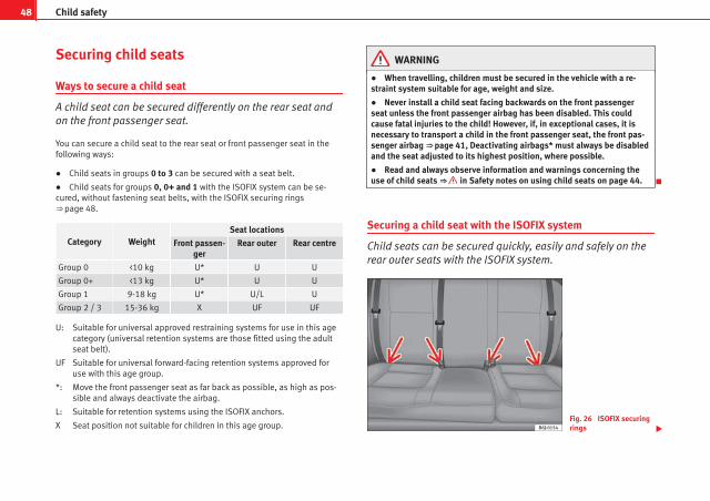
48 Child safety
Securing child seats
Ways to secure a child seat
A child seat can be secured differently on the rear seat andon the front passenger seat.
You can secure a child seat to the rear seat or front passenger seat in thefollowing ways:
● Child seats in groups 0 to 3 can be secured with a seat belt.
● Child seats for groups 0, 0+ and 1 with the ISOFIX system can be se-cured, without fastening seat belts, with the ISOFIX securing rings⇒ page 48.
Category WeightSeat locations
Front passen-ger
Rear outer Rear centre
Group 0 <10 kg U* U U
Group 0+ <13 kg U* U U
Group 1 9-18 kg U* U/L U
Group 2 / 3 15-36 kg X UF UF
Suitable for universal approved restraining systems for use in this agecategory (universal retention systems are those fitted using the adultseat belt).
Suitable for universal forward-facing retention systems approved foruse with this age group.
Move the front passenger seat as far back as possible, as high as pos-sible and always deactivate the airbag.
Suitable for retention systems using the ISOFIX anchors.
Seat position not suitable for children in this age group.
U:
UF
*:
L:
X
WARNING
● When travelling, children must be secured in the vehicle with a re-straint system suitable for age, weight and size.
● Never install a child seat facing backwards on the front passengerseat unless the front passenger airbag has been disabled. This couldcause fatal injuries to the child! However, if, in exceptional cases, it isnecessary to transport a child in the front passenger seat, the front pas-senger airbag ⇒ page 41, Deactivating airbags* must always be disabledand the seat adjusted to its highest position, where possible.
● Read and always observe information and warnings concerning theuse of child seats ⇒ in Safety notes on using child seats on page 44.
Securing a child seat with the ISOFIX system
Child seats can be secured quickly, easily and safely on therear outer seats with the ISOFIX system.
Fig. 26 ISOFIX securingrings

49Child safety
When removing or fitting the child seat, please be sure to followthe manufacturer's instructions.
– Press the child seat onto the ISOFIX retaining rings until thechild seat can be heard to engage securely. If the child seat isfitted with any other anti-rotation system, follow the manufac-turer instructions carefully.
– Pull on both sides of the child seat to ensure that it is secure.
Two ISOFIX retaining rings are fitted on each rear seat. In some vehicles, therings are secured to the seat frame and, in others, they are secured to therear floor. The access to the ISOFIX rings is between the rear seat backrestand the seat cushioning.
Child seats with ISOFIX mountings are available in your Authorised ServiceCentres.
WARNING
● The retaining rings are designed to only be used with ISOFIX childseats.
● Never secure child seats without the ISOFIX system, retaining belts orobjects to the fastening rings – this can result in potentially fatal injuriesto the child.
● Ensure that the child seat is secured correctly to the ISOFIX anchorpoints.
Top Tether retainer straps
Some child restraint seats have a third Top Tether anchoringpoint, apart from both ISOFIX anchoring points, which allowbetter child retention.
Fig. 27 Position of theTop Tether rings on theback of the rear seat
Child seats with the Top Tether system come with a strap for securing theseat to the vehicle anchor point, located at the back of the rear backrest.
The retainer strap is used to reduce forwards movements of the safety seatin a crash, helping reduce the risk of injuries to the head from hitting theinside of the vehicle.
It is foreseen that an EU Directive will introduce requirements related to theretention of child restraint systems by means of ISOFIX and Top Tether an-chorages (probably compulsory for new types from 2010), which will entailimproved retention of the child restraint seat and less head movement incase of frontal collisions.
Safety First Operating Instructions Practical Tips Technical Specifications

50 Child safety
Use of retainer straps on rear-facing seats
At present there are very few rear-facing child safety seats fitted with a re-tainer strap. Please carefully read and follow the safety seat manufacturer'sinstructions for information on how to install the retainer strap properly.
WARNING
An undue installation of the safety seat will increase the risk of injury inthe event of a crash.
● Never tie the retainer strap to a hook in the luggage compartment.
● Never secure or tie luggage or other items to the lower anchorages(ISOFIX) or the upper ones (Top Tether).
Fitting the Top Tether child restraint to the anchoring point
Fig. 28 Retainer strap:correct adjustment andfitting
Securing the Top Tether child restraint to the anchor point situatedon the rear of the backrest
– Pull out the fastening belt of the child restraint seat accordingto the manufacturer's instructions.
– Lead the Top Tether fastening belt under the rear seat head re-straint ⇒ fig. 28 (lift the head restraint where necessary).
– Slide the belt so that the Top Tether belt of the child restraintseat is correctly secured to the anchor on the back of the rearseat.
– Firmly tighten the Top Tether belt following the child restraintseat manufacturer's instructions.
Releasing the retaining strap
– Release the retainer strap in line with the instructions given bythe child safety seat manufacturer.
– Push the lock and release it from the anchoring support.
WARNING
Read and bear in mind all the WARNINGS ⇒ page 49.

51Child safety
Safety First Operating Instructions Practical Tips Technical Specifications

52 Cockpit
Fig. 29 Dash panel
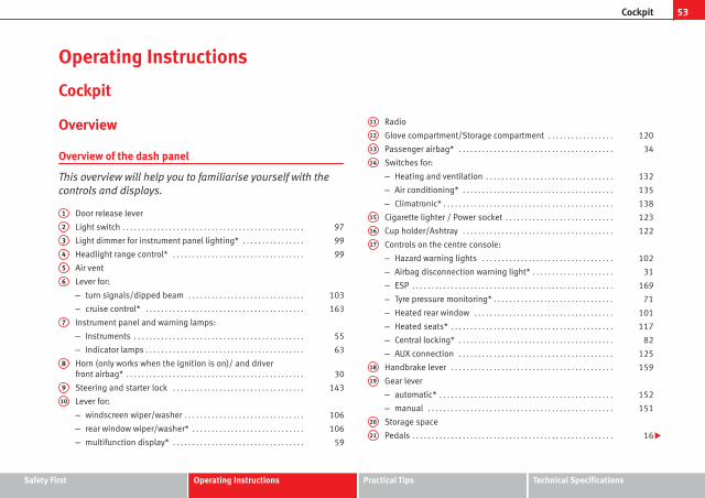
53Cockpit
Operating Instructions
Cockpit
Overview
Overview of the dash panel
This overview will help you to familiarise yourself with thecontrols and displays.
Door release lever
Light switch . . . . . . . . . . . . . . . . . . . . . . . . . . . . . . . . . . . . . . . . . . . . . . . 97
Light dimmer for instrument panel lighting* . . . . . . . . . . . . . . . . 99
Headlight range control* . . . . . . . . . . . . . . . . . . . . . . . . . . . . . . . . . . 99
Air vent
Lever for:
– turn signals/dipped beam . . . . . . . . . . . . . . . . . . . . . . . . . . . . . . 103
– cruise control* . . . . . . . . . . . . . . . . . . . . . . . . . . . . . . . . . . . . . . . . . 163
Instrument panel and warning lamps:
– Instruments . . . . . . . . . . . . . . . . . . . . . . . . . . . . . . . . . . . . . . . . . . . . 55
– Indicator lamps . . . . . . . . . . . . . . . . . . . . . . . . . . . . . . . . . . . . . . . . . 63
Horn (only works when the ignition is on)/ and driverfront airbag* . . . . . . . . . . . . . . . . . . . . . . . . . . . . . . . . . . . . . . . . . . . . . . 30
Steering and starter lock . . . . . . . . . . . . . . . . . . . . . . . . . . . . . . . . . . 143
Lever for:
– windscreen wiper/washer . . . . . . . . . . . . . . . . . . . . . . . . . . . . . . . 106
– rear window wiper/washer* . . . . . . . . . . . . . . . . . . . . . . . . . . . . . 106
– multifunction display* . . . . . . . . . . . . . . . . . . . . . . . . . . . . . . . . . . 59
1
2
3
4
5
6
7
8
9
10
Radio
Glove compartment/Storage compartment . . . . . . . . . . . . . . . . . 120
Passenger airbag* . . . . . . . . . . . . . . . . . . . . . . . . . . . . . . . . . . . . . . . . 34
Switches for:
– Heating and ventilation . . . . . . . . . . . . . . . . . . . . . . . . . . . . . . . . . 132
– Air conditioning* . . . . . . . . . . . . . . . . . . . . . . . . . . . . . . . . . . . . . . . 135
– Climatronic* . . . . . . . . . . . . . . . . . . . . . . . . . . . . . . . . . . . . . . . . . . . . 138
Cigarette lighter / Power socket . . . . . . . . . . . . . . . . . . . . . . . . . . . . 123
Cup holder/Ashtray . . . . . . . . . . . . . . . . . . . . . . . . . . . . . . . . . . . . . . . 122
Controls on the centre console:
– Hazard warning lights . . . . . . . . . . . . . . . . . . . . . . . . . . . . . . . . . . 102
– Airbag disconnection warning light* . . . . . . . . . . . . . . . . . . . . . 31
– ESP . . . . . . . . . . . . . . . . . . . . . . . . . . . . . . . . . . . . . . . . . . . . . . . . . . . . 169
– Tyre pressure monitoring* . . . . . . . . . . . . . . . . . . . . . . . . . . . . . . . 71
– Heated rear window . . . . . . . . . . . . . . . . . . . . . . . . . . . . . . . . . . . . 101
– Heated seats* . . . . . . . . . . . . . . . . . . . . . . . . . . . . . . . . . . . . . . . . . . 117
– Central locking* . . . . . . . . . . . . . . . . . . . . . . . . . . . . . . . . . . . . . . . . 82
– AUX connection . . . . . . . . . . . . . . . . . . . . . . . . . . . . . . . . . . . . . . . . 125
Handbrake lever . . . . . . . . . . . . . . . . . . . . . . . . . . . . . . . . . . . . . . . . . . 159
Gear lever
– automatic* . . . . . . . . . . . . . . . . . . . . . . . . . . . . . . . . . . . . . . . . . . . . . 152
– manual . . . . . . . . . . . . . . . . . . . . . . . . . . . . . . . . . . . . . . . . . . . . . . . . 151
Storage space
Pedals . . . . . . . . . . . . . . . . . . . . . . . . . . . . . . . . . . . . . . . . . . . . . . . . . . . . 16
11
12
13
14
15
16
17
18
19
20
21
Safety First Operating Instructions Practical Tips Technical Specifications

54 Cockpit
Steering column control lever* . . . . . . . . . . . . . . . . . . . . . . . . . . . . . 142
Bonnet release lever . . . . . . . . . . . . . . . . . . . . . . . . . . . . . . . . . . . . . . 201
Steering column controls for audio and telephone* . . . . . . . . . 76
Fuse housing . . . . . . . . . . . . . . . . . . . . . . . . . . . . . . . . . . . . . . . . . . . . . 229
Control for adjusting electric exterior mirrors* . . . . . . . . . . . . . . . 111
Electric window controls* . . . . . . . . . . . . . . . . . . . . . . . . . . . . . . . . . . 92
NoteSome of the items of equipment listed here are fitted only on certain modelversions or are optional extras.
22
23
24
25
26
27

55Cockpit
Instruments
Instrument overview
The instruments display the vehicle operating status.
Fig. 30 Detailed view of the dash panel: instrumentpanel
The layout of the instruments depends upon the model and the engine.
Rev counter* ⇒ page 56
Digital display ⇒ page 57
Speedometer ⇒ page 56
Menu selection button on the instrument panel digital display
Adjustment button depending on the selected menu
1
2
3
4
5
Safety First Operating Instructions Practical Tips Technical Specifications

56 Cockpit
Rev counter
The rev counter displays the engine speed in revolutions perminute.
The start of the red zone ⇒ fig. 30 1 indicates the maximum engine speedoperating at service temperature. However, it is advisable to change up a in-to a higher gear, move the selector lever to D or lift your foot off the acceler-ator before the needle reaches the red zone.
CAUTIONThe rev counter needle must never enter the red zone on the scale. Risk ofengine damage.
For the sake of the environmentChanging up into higher gears sooner, following the recommended gear in-dications ⇒ fig. 33 will help you to reduce fuel consumption, emissions andalso engine noise.
Speedometer
The speedometer is equipped with a digital odometer and a trip recorder, inaddition to a service intervals display.
During the running-in period, the instructions shown on ⇒ page 172should be followed.
LPG system*
LPG gauge
Fig. 31 Instrument pan-el: gas gauge.
LPG system filler level display
The LPG tank ⇒ in the spare wheel well has a capacity of 52.8 litres at anoutside temperature of 15 °C ⇒ page 195, Refuelling with LPG.
The charge level can be checked on the analogue gas gauge located on theinstrument panel ⇒ fig. 31. When the level reaches reserve, the gas reservewarning lamp lights up and an acoustic signal is heard. Refill with LPG atthe earliest opportunity.
If, while driving in LPG mode, a sudden warning signal is heard and thewarning ERROR FUNC_ A GAS is displayed on the screen1), it means thatthere is a fault in the LPG system. Take the vehicle to a specialised work-shop to check the LPG system.
1) Depending on the model version

57Cockpit
WARNING
LPG is a highly explosive and inflammable substance. It may cause se-vere burns and other injury.
● Due care must be taken to avoid any risk of fire or explosion.
● When parking the vehicle in a closed area (for example in a garage),make sure that there is adequate ventilation, either natural or mechani-cal, to neutralise the LPG in the event of a leak.
Note● The values shown in the average fuel consumption and distance to emp-ty indications on the multifunction display (MFI)1) on the instrument panel2)
are approximate values only.
● Two different consumption values are given on the MFI, depending onwhether the vehicle is running in GAS or Petrol mode.
● Please check the fuel level on the fuel level gauge on the instrumentpanel ⇒ page 57
● If frequent short journeys are made, especially when the outside tem-perature is low, the vehicle will tend to run on petrol more often than onLPG. Therefore, the petrol tank may empty before the LPG tank.
Digital instrument panel display
Fuel gauge and reserve indicator
Fig. 32 Fuel gauge
Instrument panel: fuel gauge
The fuel tank has a capacity of approx. 45 litres.
When the needle reaches the reserve zone ⇒ fig. 32, the warning lamp willlight and an acoustic signal will sound reminding the driver to refuel. Atthis point there are still 7 litres of fuel in the tank.
1) Optional equipment2) Depending on the model version
Safety First Operating Instructions Practical Tips Technical Specifications

58 Cockpit
Digital clock*
– To set the hour, press button 4 ⇒ fig. 30. The “hour” optionflashes on the digital display and is set using button 5 “set”⇒ fig. 30.
– To set the minutes, press button 4 again and select the mi-nute option. Set from button 5 “set”.
Once the operation has been carried out, the system memorises the time.
Outside temperature display
The outside temperature is displayed when the ignition isswitched on.
At descending temperatures between +4 °C down to -7 °C and at ascendingtemperatures from -5 °C up to +6 °C, in addition to the outside temperaturedisplay, an ice crystal is displayed, and if vehicle speed is over 10 km/h anacoustic buzzer is heard.
The illumination of the crystal symbol aims to warn the driver of the risk ofice, so that he/she proceeds with due care.
When the vehicle is stationary or travelling at very low speeds, the tempera-ture displayed may be slightly higher than the actual outside temperatureas a result of heat coming from the engine.
Recommended gear display*
This display helps to save fuel.
Fig. 33 Gear display
Use the gear display to save fuel. If you are not in the correct gear, a trianglewill appear next to the gear display indicating whether you should changeup or down ⇒ fig. 33.
NoteThe gear change indication should not be taken into account the accelera-tion is required (for example when overtaking).

59Cockpit
Multifunction display (MFI)*
The multifunction display (MFI) shows you information onthe journey and fuel consumption.
Fig. 34 Windscreen wip-er lever: button A androcker switch B
The multifunction system uses two automatic memories: 1 - Actualmemory and 2 - Total memory. The selected memory will be shownin the upper right-hand corner of the display.
Selecting a memory
– With the ignition switched on, briefly press button ⇒ fig. 34 A
on the windscreen wiper lever to move from one memory to an-other.
Resetting a memory
– Select the memory that you would like to reset.
– Press and hold button A on the windscreen wiper lever for atleast 2 seconds.
The trip memory 1 collects the travel and consumption rates from the mo-ment the ignition is switched on until it is switched off. If the journey is con-tinued within two hours of switching off the ignition, the new values will beadded to the existing trip recorder memory. The memory will automaticallybe deleted if the journey is interrupted for more than two hours.
The total memory 2 collects the trip data for any number of individual jour-neys (even if the ignition is switched off for longer than two hours) up to atotal of 19 hours and 59 minutes travel time or 1999 km distance travelled.The memory will automatically be deleted if one of the named values isreached.
Information in the multifunction display (MFI)*
Fig. 35 Windscreen wip-er and windscreen washlever: button A and rockerswitch B
You can switch between the following displays in the multifunction display(MFI) by operating rocker switch ⇒ fig. 35 B on the windscreen wiper lever.
Safety First Operating Instructions Practical Tips Technical Specifications

60 Cockpit
Memory displays
● Driving speed
● Journey duration
● Average speed
● Distance
● Distance to empty
● Average fuel consumption
● Current fuel consumption
● Outside temperature display
● Speed warning
Km/h - Driving speed
Driving speed is digitally shown in the display.
min - Journey duration
The display shows the amount of time which has elapsed since the ignitionwas switched on.
The maximum display value in both memories is 19 hours and 59 minutes.The memory will automatically be deleted once this value has beenreached.
Ø mph - Average speed
After turning on the ignition, the average speed will be shown after travel-ling a distance of approximately 100 metres. Until then dashes will appearin the display. The display will be updated every 5 seconds while the vehicleis in motion.
km - Distance travelled
The display shows the distance travelled since the ignition was switched on.
The maximum display value in both memories is 1999 km. The memory willautomatically be deleted once this value has been reached.
Km - Fuel range
The fuel range is calculated using the figures for tank content and currentfuel consumption. It shows how far the vehicle can travel using the sameconditions as a reference.
Ø ltr/100km - Average fuel consumption
After turning on the ignition, average fuel consumption will be shown aftertravelling approximately 100 metres. Until then dashes will appear in thedisplay. The display will be updated every 5 seconds while the vehicle is inmotion. The amount of fuel used will not be shown.
l/100 km or l/h - Current fuel consumption
The display will show the current fuel consumption in litre/km whilst the ve-hicle is in motion or in litre/hour when the vehicle is in a stationary positionwith the engine running.
Using this display you can see how your driving style affects fuel consump-tion ⇒ page 172.
Outside temperature display
The measurement margin extends from -45 °C to +58 °C. At temperatureslower than +4 °C, an “ice crystal symbol” is displayed and a “warning”sounds if the vehicle is moving at more than 10 km/h (ice warning). Thissymbol will flash for about 10 seconds and remains lit until the exterior tem-perature rises above +4 °C or 6 °C if it was already lit.
Set speed indicator
When the required speed has been reached, enter the “Speed warning”mode menu and press button A -RESET-. The set speed is memorised. Ifthe indicated speed is exceeded at any time, a warning message is dis-played on the screen and a warning signal sounds.1)
1) Depending on the model version, the message on the screen may vary and may be repre-sented by flashing of the speed indication or by a speed message.

61Cockpit
This may be deactivated by pressing the RESET button. The speed may bealtered using the rocker switch B in steps of 5 km/h within 5 seconds ofthe initial memory value.
WARNING
There could be black ice on the road surface even if the “snowflake sym-bol” is not shown. For this reason you should not rely exclusively on thisdisplay - Risk of accident!
NoteWhen the vehicle is stationary or travelling at very low speeds, the tempera-ture displayed may be slightly higher than the actual outside temperatureas a result of the heat radiated from the engine.
Display field for selector lever position*
Fig. 36 Digital display:Gear lever position forautomatic gearbox.
The position of the automatic selector lever is shown on the display⇒ page 152.
Odometer
The upper counter in the display registers the total mileage covered by thevehicle.
The lower counter registers the short journeys. The last digit indicates 100-metre sections. The trip recorder counter may be reset by pressing the resetbutton ⇒ fig. 30 5 .
Service interval display
Fig. 37 Service intervaldisplay
The service indication is shown on the instrument panel display ⇒ fig. 37.
Safety First Operating Instructions Practical Tips Technical Specifications

62 Cockpit
SEAT distinguishes between services with engine oil change (e.g. Mainte-nance Service) and services without engine oil change (e.g. Inspection Serv-ice). The service interval display only indicates the dates of services that in-clude engine oil change. The dates of all other services, such as InspectionService or brake fluid change, appear in the sticker on the door pillar or inthe Service Schedule.
Vehicles with service intervals dependent on time/distance travelled al-ready have certain service intervals set.
The intervals are calculated separately in vehicles with LongLife serviceTechnical progress has made it possible to considerably reduce servicing re-quirements. With the LongLife System, SEAT ensures that your vehicle onlyhas an interval service when it is necessary. To calculate this (max. twoyears), the conditions under which the vehicle is used and the individualdriving style are also taken into account. The service pre-warning will ap-pear at 20 days or less prior to the corresponding service. The distance trav-elled is rounded off to the nearest 100 km and the time to full days. The cur-rent service message can only be consulted 500 km or more after the lastservice. Until that time, only dashes are displayed.
Service warning
A service warning will appear when the ignition is switched on if a service isdue soon.
The instrument panel display will show the “spanner symbol” and the“km” indication, along with a clock symbol with the days remaining untilthe date of the next service. The figure indicated is the maximum number ofkilometres remaining before the date of the next service. The indicationchanges after a few seconds. A “clock symbol” appears and the number ofdays until the service appointment should be carried out.
Service
If a service is due, a gong signal will sound and the flashing “spanner” symbol will be shown along with the fixed text SERVICE.
If no service is carried out following the indication on the instrument panel,the excess distance travelled and the excess time following the SERVICEwarning will be displayed.
Reading the service message
The current service message can be consulted with the ignition on, the en-gine switched off and the vehicle at a standstill:
● Press the button on the instrument panel as often as necessary untilthe spanner symbol is displayed.
An overdue service is indicated by a minus sign in front of the mileage orday information.
Resetting service interval display
If the service was not performed by a SEAT dealer, the display must be resetas follows:
● Switch the ignition off.
● Press and hold the 0.0 / SET button.
● Switch ignition back on.
● Release the 0.0 / SET button and press the button within 20 seconds.
Do not reset the display between service intervals, as the display will other-wise be incorrect.
If the display is reset manually, the next service interval will be indicated af-ter 15 000 km or one year and will not be calculated individually.
NoteIn LongLife Service vehicles, if the battery is disconnected for a long period,the days remaining until the next service cannot be calculated. Therefore,the service message indications may be incorrect. In this case, bear in mindthe maximum service intervals permitted in the ⇒ Booklet Service Schedule.

63Cockpit
Warning lamps
Overview of the warning lamps
The warning lamps indicate a number of different functions and possible faults.
Fig. 38 Instrument panel warning and indicator lamps.Some of the items of equipment listed here are fittedonly on certain model versions or are optional extras.
Safety First Operating Instructions Practical Tips Technical Specifications
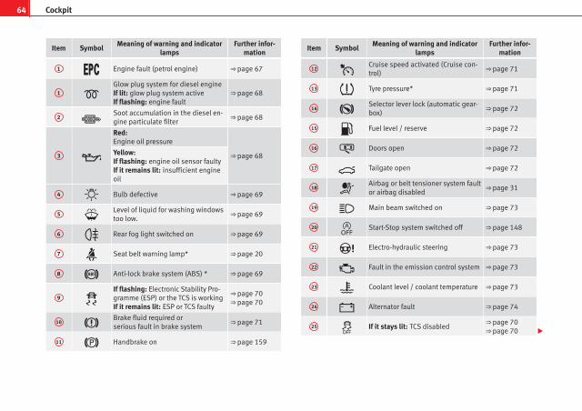
64 Cockpit
Item SymbolMeaning of warning and indicator
lampsFurther infor-
mation
1 Engine fault (petrol engine) ⇒ page 67
1 Glow plug system for diesel engineIf lit: glow plug system activeIf flashing: engine fault
⇒ page 68
2 Soot accumulation in the diesel en-gine particulate filter
⇒ page 68
3
Red:Engine oil pressure
⇒ page 68Yellow:If flashing: engine oil sensor faultyIf it remains lit: insufficient engineoil
4 Bulb defective ⇒ page 69
5 Level of liquid for washing windowstoo low.
⇒ page 69
6 Rear fog light switched on ⇒ page 69
7 Seat belt warning lamp* ⇒ page 20
8 Anti-lock brake system (ABS) * ⇒ page 69
9 If flashing: Electronic Stability Pro-gramme (ESP) or the TCS is workingIf it remains lit: ESP or TCS faulty
⇒ page 70⇒ page 70
10 Brake fluid required orserious fault in brake system
⇒ page 71
11 Handbrake on ⇒ page 159
Item SymbolMeaning of warning and indicator
lampsFurther infor-
mation
12 Cruise speed activated (Cruise con-trol)
⇒ page 71
13 Tyre pressure* ⇒ page 71
14 Selector lever lock (automatic gear-box)
⇒ page 72
15 Fuel level / reserve ⇒ page 72
16 Doors open ⇒ page 72
17 Tailgate open ⇒ page 72
18 Airbag or belt tensioner system faultor airbag disabled
⇒ page 31
19 Main beam switched on ⇒ page 73
20 Start-Stop system switched off ⇒ page 148
21 Electro-hydraulic steering ⇒ page 73
22 Fault in the emission control system ⇒ page 73
23 Coolant level / coolant temperature ⇒ page 73
24 Alternator fault ⇒ page 74
25 If it stays lit: TCS disabled⇒ page 70⇒ page 70

65Cockpit
Item SymbolMeaning of warning and indicator
lampsFurther infor-
mation
Turn signals in operation ⇒ page 74
SAFE Electronic immobiliser⇒ page 74⇒ page 79
WARNING
● Failure to observe warning lamps and warning messages can result inserious personal injuries or damage to your vehicle.
● The risk of an accident increases if your vehicle breaks down. Use awarning triangle to draw the attention of other road users in order to pre-vent danger to third parties.
● The engine compartment is a dangerous area! Before you open thebonnet to work on the engine or in the engine compartment, you mustswitch the engine off and allow it to cool to reduce the risk of scalding orother injuries. Read and observe the relevant warnings ⇒ page 199.
Note● The appropriate warning lamp for a fault will light up in vehicles withoutwarning or information messages in the display.
● In vehicles with warning or information texts on the screen, the appro-priate warning lamp for a fault will light up and a warning or informationmessage will also appear on the screen.
Overview of indicator and warning lamps (vehicles withLPG)
The warning lamps indicate a number of different functionsand possible faults.
Fig. 39 Instrument panel indicator and warning lamps in vehicles with LPG.
Item SymbolMeaning of warning and indicator
lampsFurther infor-
mation
1 Green: LPG system connected ⇒ page 147
2 Yellow: Gas reserve warning light ⇒ page 56
Safety First Operating Instructions Practical Tips Technical Specifications

66 Cockpit
WARNING
● Failure to observe warning lamps and warning messages can result inserious personal injury or damage to your vehicle.
● The risk of an accident increases if your vehicle breaks down. Use awarning triangle to draw the attention of other road users in order to pre-vent danger to third parties.
● The engine compartment is a dangerous area! Before you open thebonnet to work on the engine or in the engine compartment, you mustswitch the engine off and allow it to cool to reduce the risk of scalding orother injuries. Read and observe the relevant warnings ⇒ page 199.
Note● The appropriate warning lamp for a fault will light up in vehicles withoutwarning or information messages in the display.
● In vehicles with warning or information texts on the screen, the appro-priate warning lamp for a fault will light up and a warning or informationmessage will also appear on the screen.
Warning symbols
There are red warning symbols (priority 1) and yellow warning sym-bols (priority 2)
Warning reports, Priority 1 (red)
If one of these faults occurs, the warning lamp will flash or light up and willbe accompanied by three audible warnings. This is a danger warning. Stopthe vehicle and switch off the engine. Check the fault and correct it. Obtainprofessional assistance if necessary.
If several priority 1 faults are detected at the same time, the symbols will bedisplayed one after the other for about 2 seconds at a time and will contin-ue until the fault is corrected.
No menus will be shown in the display for the duration of a priority 1 warn-ing message.
Examples of priority 1 warning messages (red)
● Brake system symbol with the warning message STOP BRAKE FLUIDSERVICE MANUAL or STOP BRAKE FAULT SERVICE MANUAL.
● Coolant symbol with the warning message STOP SEE COOLANT IN-STRUCTION MANUAL.
● Engine oil pressure symbol with the warning message STOP ENGINEOIL PRESSURE LOW! INSTRUCTION MANUAL.
Warning reports, Priority 2 (yellow)
If one of these faults occurs, the warning lamp lights up, and is accompa-nied by one audible warning. Check the corresponding function as soon aspossible although the vehicle may be used without risk.
If several priority 2 warning messages are detected at the same time, thesymbols are displayed one after the other for about 2 seconds at a time. Af-ter a set time, the information text will disappear and the symbol will beshown as a reminder at the side of the display.
Priority 2 warning messages will not be shown until all Priority 1 warningmessages have been dealt with!
Examples of priority 2 warning messages (yellow):1)
● Fuel warning light with the information text PLEASE REFUEL.
1) Depending on the version of the model.

67Cockpit
Information messages displayed on the screen*
Messagea) Description
SERVICEThe service interval has ended. Take the vehicle to an au-thorised service.
IMMOBILIS-ER
Immobiliser system active. The vehicle will not start. Takethe vehicle to an authorised service.
ERRORInstrument panel faulty. Take the vehicle to an authorisedservice.
CLEAN AIRFILTER
Warning: Clean the air filter.
NO KEY Warning: Correct key cannot be found in the vehicle.
KEY BATTERY Warning: Key battery low. Change the battery.
CLUTCHWarning: Press the clutch to start. In vehicles with manualgearbox and Start/Stop system.
--> P/NWarning: Place the selector level in P/N to start. Only in ve-hicles with automatic gearbox.
--> PWarning: Place the selector lever in position P to stop theengine.
STARTINGWarning: The engine starts automatically. Start-Stop systemactivated.
START MAN-UALLY
Warning: The engine must be started manually. Start-Stopsystem activated.
ERRORSTART STOP
Warning: Start-Stop system error.
START STOPIMPOSSIBLE
Warning: Although the Start-Stop system is switched on, theengine cannot be stopped automatically. Not all the neces-sary conditions are met.
START STOPACTIVE
Warning: Start-Stop system activated. Vehicle in Stop mode.
SWITCH OFFWarning: Start-Stop system activated. Switch off the ignitionwhen you leave the vehicle.
STOP TRANS-MISSIONTOO HOT
Warning: Stop the engine. Gearbox overheated.
BRAKEWarning: To start the engine, press the brake pedal. Only invehicles with automatic gearbox.
COASTINGFUNCTION
Warning: Coasting mode active. Transmission engaged. On-ly in vehicles with automatic gearbox.
CHECK SAFE-LOCK
Notification of central locking function activated.
a) These messages may vary according the version of the vehicle model.
Engine management*
This warning lamp monitors the engine management sys-tem for petrol engines.
The warning lamp (Electronic Power Control) lights up when the ignitionis switched on to show that the lamp is working properly. It should go outonce the engine is started.
If there is a fault in the electronic engine management system while you aredriving, this warning lamp will light up. Stop the vehicle and seek technicalassistance.
Safety First Operating Instructions Practical Tips Technical Specifications

68 Cockpit
Glow plug system / Engine fault*
The warning lamp lights up to show that the glow plugs arepreheating. It flashes if there is an engine fault.
Warning lamp is lit
The warning lamp lights up while the glow plugs are preheating. Whenthe warning lamp goes off, the engine should be started straight away.
Warning lamp flashes
If a fault develops in the engine management system while you are driving,the glow plug lamp will flash . Take the vehicle to an Authorised ServiceCentre as soon as possible and have the engine checked.
Soot accumulation in the diesel engine particulate filter*
If the warning lamp lights up you should help the filter clean itself bydriving in the appropriate manner.
To do this, drive about 15 minutes in fourth or fifth gear (automatic gear-box: S gear range) at a speed of 60 km/h, with the engine running at ap-proximately 2000 rpm. In this way, the pollen build up in the filter is burned.When cleaning is successful, the indicator turns off.
If the warning lamp does not turn off, or the three lamps turn on (partic-ulate filter , emission control system fault and glow plugs ), takethe vehicle to a specialised workshop to repair the fault.
WARNING
● Always drive according to the road weather conditions, the terrainand traffic. Driving recommendations should never lead to illegal ma-noeuvres in surrounding traffic.
● The diesel engine particulate filter may reach extremely high temper-atures; it should not enter into contact with flammable materials under-neath the vehicle. Otherwise there is a risk of fire.
Engine oil pressure
If this warning lamp is red it indicates that the engine oilpressure is too low.
If this warning symbol starts to flash, and is accompanied by three audiblewarnings, switch off the engine and check the oil level. If necessary, addmore oil ⇒ page 204.
If the symbol flashes although the oil level is correct, do not drive on. Theengine must not even run at idle speed. Obtain technical assistance.
Checking the oil level
If the warning lamp is yellow the engine oil level should be checked assoon as possible. Top up the oil ⇒ page 204 at the next opportunity.
Oil level sensor faulty*
If the yellow warning lamp flashes, take the vehicle to a specialisedworkshop to have the oil level sensor checked. Until then it is advisable tocheck the oil level every time you refuel.

69Cockpit
Bulb defect*
The indicator lights up when a bulb is not functioning.
The warning lamp lights up when there is a fault on the turn signals,headlights, side lights and fog lights.
Washer fluid
This warning lamp lights up to indicate that the windscreenwasher level is too low.
This serves as a reminder to fill up the reservoir at the earliest opportunity⇒ page 208
Rear fog light*
This warning lamp lights up when the rear fog light is switched on . Forfurther information see ⇒ page 97.
Anti-lock brake system (ABS)*
A warning lamp monitors the ABS.
The indicator lamp should light up for a few seconds when the ignition isswitched on. It goes out again after the system has run through an automat-ic test sequence.
There is a fault in the ABS if:
● The warning lamp does not light up when the ignition is switched on.
● The warning lamp does not go out again after a few seconds
● The warning lamp lights up when the vehicle is moving
The vehicle can still be braked in the normal way, without the ABS function.Take the vehicle to a specialised workshop as soon as possible. For furtherinformation on the ABS go to ⇒ page 168.
If there is a fault in the ABS, the ESP* and the tyre pressure warning lampwill also light up.
Brake system fault
If the ABS warning lamp lights up together with the brake warning lamp, this indicates not only a fault in the ABS function, but also a possiblefault in the brake system ⇒ .
WARNING
● Before opening the bonnet, read and observe the warnings on⇒ page 199, Working in the engine compartment.
● If the brake warning lamp should light up together with the ABSwarning lamp , stop the vehicle immediately and check the brake fluidlevel in the reservoir ⇒ page 211, Brake fluid. If the fluid level has drop-ped below the “MIN” mark you must not drive on. Risk of accident. Ob-tain technical assistance.
● If the brake fluid level is correct, the fault in the brake system mayhave been caused by a failure of the ABS system. This could cause therear wheels to lock quickly when you brake. This could cause the rear tobreak away. Risk of skidding. Stop the vehicle and seek technical assis-tance.
Safety First Operating Instructions Practical Tips Technical Specifications
70 Cockpit
Differential lock fault (EDL)*
EDL operates along with the ABS in vehicles equipped withan Electronic Stability Programme (ESP)*
A malfunction in the EDL is indicated by the ABS warning lamp . Take thevehicle to a specialised workshop as soon as possible. For further informa-tion on the EDL see ⇒ page 170, Electronic differential lock (EDL)*.
Traction control system (TCS)* /
The traction control system prevents the driven wheels fromspinning when the vehicle is accelerating
There are two warning lamps for the traction control system: and . Bothwarning lamps light up together when the ignition is switched on andshould turn off after approximately 2 seconds. This is the time taken for thefunction check.
The lamp has the following function:
● It flashes when the TCS is on, and the vehicle is moving.
If the system is deactivated or if it has any fault, the warning lamp will re-main lit. It will also come on if a fault should occur in the ABS because theTCS operates in conjunction with the ABS. For further information, see⇒ page 167, Brakes
The lamp provides information about the disconnection status of thesystem:
● It stays lit when the TCS is disconnected after pressing the TCS OFFswitch.
By pressing again, TCS function is reactivated and the warning lamp switch-ed off.
Electronic Stability Programme (ESP)* /
There are two warning lamps for the electronic stability pro-gramme. The lamp provides information concerning thefunction and the provides information on the disconnec-tion status
Both warning lamps light up together when the ignition is switched on andshould turn off after approximately 2 seconds. This is the time taken for thefunction check.
This programme includes the ABS, EDL and TCS. It also includes emergencybraking assistance (BAS).
The warning lamp has the following functions:
● It flashes when the TCS/ESP is activated when driving.
● It will light up continuously if there is a malfunction in the ESP.
● It will also come on if a fault should occur in the ABS because the ESPoperates in conjunction with the ABS.
If the ESP warning lamp lights up and stays on after the engine is started,this may mean that the control system has temporarily switched off the ESP.In this case the ESP can be reactivated by switching the ignition off andthen on again. If the warning lamp goes out, this means the system is fullyfunctional.
The lamp provides information about the disconnection status of thesystem:
● It stays lit when the TCS is disconnected after pressing the switch.

71Cockpit
Brake system*
This warning lamp lights up if the brake fluid level is too lowor if there is a fault in the system.
This warning lamp lights up if
● the brake fluid level is too low ⇒ page 211.
● there is a fault in the brake system.
This warning lamp can light up together with the ABS system warning lamp.
WARNING
● If the brake warning lamp does not go out, or if it lights up when driv-ing, the brake fluid level ⇒ page 211, Brake fluid in the reservoir is toolow. Risk of accident. Stop the vehicle and do not drive on. Obtain techni-cal assistance.
● If the brake warning lamp lights up together with the ABS warninglamp , the control function of the ABS could be out of action. This couldcause the rear wheels to lock quickly when you brake. This could causethe rear to break away. Risk of skidding. Stop the vehicle and seek tech-nical assistance.
Cruise speed (Cruise control)*
The warning lamp comes on when the cruise control systemis switched on.
The warning lamp lights up when the cruise control system is switchedon. For further information on the cruise control system, see ⇒ page 163.
Tyre pressure*
Fig. 40 Centre console:tyre monitor system but-ton
The tyre warning lamp1) compares wheel revolutions and with this informa-tion, the diameter of each wheel using the ESP sensors. If the diameter of awheel changes, the tyre warning lamp lights up. The wheel diameterchanges when:
● Tyre pressure is insufficient.
● The tyre structure is damaged.
● The vehicle is unbalanced because of a load.
● The wheels of one axle are under more pressure (for example, drivingwith a trailer or on extreme slopes).
● The vehicle is fitted with snow chains.
● The temporary spare wheel is fitted.
● The wheel on one axle is changed.
1) Depending on the model version
Safety First Operating Instructions Practical Tips Technical Specifications

72 Cockpit
Tyre pressure adjustment
Following the modification to tyre pressure or changing one or more wheels,the button ⇒ fig. 40 must be kept pressed while the ignition is on until anacoustic signal is heard.
If the wheels are under excessive load (for example, driving with a trailer orheavy load), the tyre pressure must be increased to the recommended valuefor a full load (see the sticker on the inside of the fuel flap). If the tyre moni-tor system button is pressed down, the new tyre pressures are confirmed.
The tyre pressure warning lamp lights up
If the tyre pressure of a wheel is much lower than the value set by the driver,then the tyre pressure warning lamp ⇒ will light up.
WARNING
● When the tyre pressure warning lamp lights up, reduce speed imme-diately and avoid any sudden manoeuvre or braking. Stop when possible,and check the tyre pressure and status.
● The driver is responsible for maintaining correct tyre pressures. Forthis reason, tyre pressure must be regularly checked.
● Under certain circumstances (for example, when driving in a sports-like manner, in winter conditions or on a dirt track) the tyre warning lampmay light up or function incorrectly.
NoteIf the battery is disconnected, the yellow warning lamp lights up afterturning the ignition on. This should turn off after a brief journey.
Speed selector lever lock*
The brake pedal must be depressed when this warning lamp lights up. Thisis necessary when the automatic gearbox* selector lever is moved out of thepositions P or N.
Fuel level/reserve
This symbol lights up to indicate that the fuel tank is underthe reserve level.
It lights up when only 7 litres of fuel remain in the tank. Moreover, a warn-ing buzzer* is heard. It reminds you to fuel up the fuel tank as soon as pos-sible ⇒ page 193.
Indicates that the doors are open*
This warning lamp lights up if one of the doors or the tail-gate is open.
The warning light should go off when all the doors are closed correctly.
Tailgate open*
The warning lamp should switch off when the tailgate is fully closed.
73Cockpit
Main beam headlights
This warning lamp lights up when the main beams are on.
The warning lamp is switched on once main beams are on or once theheadlight flasher is operating.
For further information see ⇒ page 103.
Electro-hydraulic steering*
The level of steering assistance depends on the vehicle speed and on thesteering wheel turning speed.
The warning lamp should light up for a few seconds when the ignition isswitched on. It should go out once the engine is started.
There is a fault in the electro-hydraulic steering system if the lamp does notgo out or lights up whilst the vehicle is in motion. Take the vehicle to theAuthorised Service Centre as soon as possible.
NoteWhen towing the vehicle with the engine stopped or due to a fault in thepower steering, this will not operate. The vehicle can still be steered, but itwill require greater force to turn the steering wheel.
Emission control system*
This warning lamp monitors the exhaust system.
Warning lamp flashes:
When there is misfiring that can damage the catalytic converter. Reducespeed and drive carefully to the nearest specialised workshop to have theengine checked.
Warning lamp is lit:
If a fault has developed during driving which has reduced the quality of theexhaust gas (e.g. lambda probe fault). Reduce speed and drive carefully tothe nearest specialised workshop to have the engine checked.
Coolant level* /temperature
The warning lamp lights up if the coolant temperature is toohigh or if the coolant level is too low.
There is a fault if:
● The warning symbol does not go out again after a few seconds.
● The warning lamp lights up or flashes while the vehicle is moving, andthree acoustic warning signals ⇒ are emitted.
This means that either the coolant level is too low or the coolant tempera-ture is too high.
Coolant temperature too high
If the warning light comes on, stop the vehicle, switch off the engine andwait for it to cool down. Check the coolant level.
If the coolant level is correct, the overheating may be caused by a malfunc-tion of the radiator fan. Check the radiator fan fuse and have it replaced ifnecessary ⇒ page 229.
Safety First Operating Instructions Practical Tips Technical Specifications

74 Cockpit
If the warning lamp lights up again after driving on for a short distance,stop the vehicle and switch the engine off. Contact an Authorised ServiceCentre or a specialised workshop.
Coolant level too low
If the warning light comes on, stop the vehicle, switch off the engine andwait for it to cool down. First check the coolant level. If the level of the cool-ant is below the “MIN” mark, top up with coolant liquid ⇒ .
WARNING
● If your vehicle is immobilised for technical reasons, move it to a safedistance from traffic. Turn the engine off, turn the hazard lights on andplace the warning triangle.
● Never open the bonnet if you can see or hear steam or coolant escap-ing from the engine compartment. Risk of scalding. Wait until you can nolonger see or hear escaping steam or coolant.
● The engine compartment is a dangerous area! Before carrying out anywork in the engine compartment, switch off the engine and allow it tocool down. Always note the corresponding warnings ⇒ page 199.
Alternator
This warning lamp signals a fault in the alternator.
The warning lamp lights up when the ignition is switched on. It shouldgo out when the engine has started running.
If the warning lamp lights up while driving, the alternator is no longercharging the battery. You should immediately drive to the nearest special-ised workshop.
You should avoid using electrical equipment that is not absolutely necessa-ry because this will drain the battery.
If the indicator flashes the voltage is insufficient for normal vehicle opera-tion.
Turn signals
The indicator lamp flashes when the turn signals are in op-eration.
Depending on which turn signal is operated, either the left or right turnsignal indicator lamp flashes. Both indicator lamps will flash at the sametime when the hazard warning lights are switched on.
If any of both turn signals fails, the indicator lamp will start flashing twicefaster than normal.
For further information on the turn signals, please see ⇒ page 103.
Electronic immobiliser “Safe”*
This warning lamp flashes if an unauthorised key is used.
Inside the key there is a chip that deactivates the electronic immobiliser au-tomatically when the key is inserted into the ignition. The immobiliser willbe activated again automatically as soon as you pull the key out of the igni-tion lock.
The instrument panel displays the following message1): SAFE. The vehiclecannot be started in this case
1) Depending on the version of the model.

75Cockpit
The engine can, however, be started if the appropriate coded SEAT genuinekey is used.
NoteThe vehicle cannot operate properly if you do not have a genuine SEAT key.
Safety First Operating Instructions Practical Tips Technical Specifications

76 Steering column controls*
Steering column controls*
General information
The column incorporates multifunctional modules from which to control au-dio and telephone functions on the vehicle.
There are two versions of the multifunction module:
● Audio version, to control the available audio functions from the steeringwheel.
● Audio version+ Telephone version, to control the available audio func-tions and the telephone system from the steering wheel.
Both versions can be used to control the Audio system (Radio, Audio CD,MP3 CD, iPod1)/USB1)).
1) If fitted in the vehicle.

77Steering column controls*
Audio Control
Fig. 41 Audio controls
ButtonShort press
Radio CD Audio CD MP3/USB/iPoda) AUX-INA Volume up
B Volume down
C Cycle through source FM - AM - CD - FM...
DStation search. Higher frequency
.Next track
No function
DStation search. Lower frequency
.Previous track
No function
E Next preset No function Change folder (forward) No function
F Previous preset No function Change folder (back) No function
a) Only for MP3 compatible radios.*
Safety First Operating Instructions Practical Tips Technical Specifications

78 Steering column controls*
Audio + Telephone Control
Fig. 42 Audio + Tele-phone Control
ButtonShort press Long press
Radio CDCD MP3/USB/
iPoda) AUX-IN Radio CDCD MP3/USB/
iPoda) AUX-IN
A Volume up Continue volume up
B Volume down Continue volume down
C Enable voice recognition. Press to speak No function specified
DStation search.
Higher frequency.
Next track No functionStation search.
Higher frequency.
Next track No function
DStation search.
Lower frequency.
Previous track No functionStation search.
Lower frequency.
Previous track No function
E Accept call / hang up Reject call
F Cycle through source FM - AM - CD - FM... Cycle through source FM - AM - CD - FM...
a) Only for MP3 compatible radios.

79Unlocking and locking
Unlocking and locking
Central locking
Description
The central locking system enables you to lock and unlockall doors by just pushing the button.
Central locking can be activated by using any of the following options:
● the key, by inserting it into the driver door cylinder and rotating it in theopening direction. Depending on the vehicle version, either all doors will beunlocked or only the driver door will be unlocked. All doors will be locked onlocking the vehicle using the key.
● the interior central locking button ⇒ page 82.
● the remote control, using the buttons on the key ⇒ page 85.
Various functions are available to improve the vehicle safety:
Safe* security system
Selective unlocking system*
Self-locking system to prevent involuntary unlocking
Automatic speed-dependent locking and unlocking system*
Emergency unlocking system
-
-
-
-
-
WARNING
● Locking from the outside carelessly or without good visibility maylead to bruising, particularly in the case of children.
● When locking a vehicle, never leave children unaccompanied inside,as from the outside it will be difficult to provide assistance if required.
● Having the doors locked prevents an intrusion from getting in, for ex-ample when stopped at a traffic light.
NoteFor anti-theft security, only the driver door is fitted with a lock cylinder.
Safe security system*
This is an anti-theft device that consists of a double lock forthe door locks and a disabling function for the luggagecompartment in order to prevent a forced entry (dependingon country).
Activation
The “safe” system is activated when the vehicle is locked using the key orthe remote control.
To activate it with the key, rotate once it is inserted in the door lock cylinderin the locking direction.
To activate the system using the remote control, press the lock button once on the remote.
Safety First Operating Instructions Practical Tips Technical Specifications
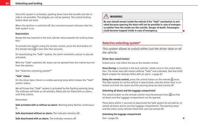
80 Unlocking and locking
Once this system is activated, opening doors from the outside and the in-side is not possible. The tailgate can not be opened. The central lockingbutton does not work.
When the ignition is switched off, the instrument panel indicates that theSafe system is on.
Deactivation
Rotate the key inserted in the lock cylinder twice towards the locking direc-tion.
To activate the system using the remote control, press the lock button onthe remote twice in less than five seconds.
On deactivating the “Safe” system, the alarm volumetric sensor is also de-activated.
With the “Safe” switched off, doors can be opened from the interior but notfrom the exterior.
See “Selective unlocking system*”
“Safe” status
On the driver door, there is a visible warning lamp which shows the “Safe”system status.
We will know that “Safe” system is activated by the flashing warning lamp.The indicator will flash on all vehicles, fitted and nor fitted with an alarm,until they unlock.
Remember:
Safe activated with or without an alarm: Warning lamp flashes continuous-ly.
Safe deactivated without an alarm: The indicator remains off.
Safe deactivated with an alarm: The indicator remains off.
WARNING
No one should remain inside the vehicle if the “Safe” mechanism is acti-vated because opening the doors will not be possible in case of emergen-cy neither from the inside nor the outside. Danger of death. Passengerscould become trapped inside in case of emergency.
Selective unlocking system*
This system allows to unlock either just the driver door or allthe vehicle.
Driver door unlock button
Unlock once. Use either the key or the remote control.
Once the key is inserted in the lock cylinder, rotate once in the unlock direc-tion. The driver door will remain without “Safe” and unlocked. See Anti-theftAlarm chapter for vehicles fitted with an alarm ⇒ page 87.
Using the remote control, press the unlock button on the remote once.The Safe system for all the vehicle is deactivated, only the driver door is un-locked and both the alarm and the warning lamp are also turned off.
Unlocking all doors and the luggage compartment
The unlock button on the remote control must be pressed twice so thatall doors and the luggage compartment can be opened.
Press twice within 5 seconds to deactivate the Safe system for all vehicle, tounlock all doors and to use the luggage compartment. The warning lampand the alarm (only vehicles fitted with one) are turned off.
Unlocking the luggage compartment
See ⇒ page 90.

81Unlocking and locking
Activating the selective unlocking system*
With the door open, insert a key into the start cylinder and start the ignition.Insert the other key into the driver door lock and turn in the opening direc-tion for at least 3 seconds. The turn signals will flash twice.
Deactivating the selective unlocking system*
With the door open, insert a key into the start cylinder and start the ignition.Insert the other key into the driver door lock and turn in the locking direc-tion for at least 3 seconds. The turn signals will flash once.
Involuntary unlocking
It is an anti-theft system and prevents the unintentional un-locking of the vehicle.
If the vehicle is unlocked and any of the doors (including the tailgate) areopened within 30 seconds, it gets re-locked automatically.
Automatic speed dependent locking and unlocking system*
This is a safety system which prevent the access to the vehi-cle from the outside when it is running (for example, whenstopped at a traffic light).
Locking
The doors lock automatically after exceeding 15km/h. The tailgate locks au-tomatically after exceeding 6 km/h.
If the vehicle is stopped and any of its doors open, when starting again andexceeding the mentioned speed, all doors will lock again.
Unlocking
On withdrawing the ignition key, the vehicle will returns to its status prior toself-locking.
Each door can be unlocked and opened independently from the inside (forexample, when a passenger gets out of it). To do it, simply operate the leverinside the door.
Activating the system*
With the ignition on, press the locking key on the central locking systemwithin 3 to 10 seconds.
Deactivating the system*
With the ignition on, press the unlocking key on the central locking systemwithin 3 to 10 seconds.
In both cases, if the operation has been carried out correctly, the lockinglamp will flash ⇒ fig. 43.
WARNING
The door handles must not be operated when the vehicle is running: thedoor would open.
NoteIf the airbags are triggered during an accident, the vehicle is unlocked, ex-cept for the luggage compartment. It is possible to lock the vehicle from in-side with the central locking, after turning the ignition off and back onagain.
Safety First Operating Instructions Practical Tips Technical Specifications

82 Unlocking and locking
Emergency unlocking system
If the airbags are triggered during an accident, the vehicle is unlocked, ex-cept for the luggage compartment. It is possible to lock the vehicle from in-side with the central locking, after turning the ignition off and back onagain.
Central locking button*
The central lock button allows you to lock and unlock the ve-hicle from the inside.
Fig. 43 Central lockingbutton
Locking the vehicle
– Press button ⇒ fig. 43 ⇒ .
Unlocking the doors
– Press the button ⇒ fig. 43.
The central lock button is still operative when the ignition is switched off.Except when the Safe security system is activated.
Please note the following if you lock your vehicle with the central lock but-ton:
● Locking the doors and tailgate prevents access from the outside (forsafety reasons, e.g. when stopped at a traffic light).
● The driver door cannot be locked. This avoids the user from forgettinghis key inside the vehicle.
● All doors can be locked separately from inside the vehicle. Do this bypulling the door release lever once.
WARNING
● If the vehicle is locked, children and disabled people may be trappedinside it.
● Repeated operation of central locking will prevent the central lockingbutton from working for a few seconds. Then, it can only be unlocked incase it has been previously locked. After few seconds, the central lockingbecomes operative again.
● The central locking button is not operative when the vehicle is lockedfrom the outside (with the remote control or the key).
Note● Vehicle locked, button.
● Vehicle unlocked, button.

83Unlocking and locking
Childproof lock
The childproof lock prevents the rear doors from beingopened from the inside. This system prevents minors fromopening a door accidentally while the vehicle is running.
Fig. 44 Childproof lockon the left hand sidedoor
This function is independent of the vehicle electronic opening andlocking systems. It only affects rear doors. It can only be activatedand deactivated manually, as described below:
Activating the childproof lock
– Unlock the vehicle and open the door in which you wish to acti-vate the childproof lock.
– With the door open, rotate the groove in the door using the igni-tion key, anti-clockwise for the left hand side doors ⇒ fig. 44and clockwise for the right hand side doors.
Deactivating the childproof lock
– Unlock the vehicle and open the door whose childproof lock youwant to deactivate.
– With the door open, rotate the groove in the door using the igni-tion key, anti-clockwise for the right hand side doors and clock-wise for the left hand side doors ⇒ fig. 44.
Once the childproof lock is activated, the door can only be opened from theoutside. The childproof lock can be activated and deactivated by insertingthe key in the groove when the door is open, as described above.
Safety First Operating Instructions Practical Tips Technical Specifications

84 Unlocking and locking
Keys
Set of keys
The set of keys includes a remote control, a key without a re-mote control and a plastic key tab*
Fig. 45 Set of keys
The set of keys may consists of the following, depending on the version ofyour vehicle:
● a remote control key ⇒ fig. 45 A
● a key without remote control B ,
● a plastic key tab* C .
or
● two keys without remote control B
● a plastic key tab* C .
Duplicate keys
If you need a replacement key, go to an Authorised Service Centre with yourvehicle identification number.
WARNING
● An incorrect use of the keys can cause serious injuries.
● Never leave children or disabled persons in the vehicle. In case ofemergency, they may not be able to leave the vehicle or manage on theirown.
● An uncontrolled use of the key could start the engine or activate anyelectric equipment (e.g. electric windows), causing risk of accident. Thedoors can be locked using the remote control key. This could make theaid difficult in an emergency situation.
● Never forget the keys inside the vehicle. An unauthorised use of yourvehicle could result in injury, damage or theft. Always take the key withyou when you leave the vehicle.
● Never remove the key from the ignition if the vehicle is in motion.Otherwise, the steering could suddenly block and it would be impossibleto steer the vehicle.
CAUTIONThere are electronic components in the remote control key. Avoid wettingand hitting the keys

85Unlocking and locking
Radio frequency remote control*
Locking and unlocking the vehicle
The remote control key is used to lock and unlock the vehiclefrom a distance.
Fig. 46 Assignment ofbuttons on the remotecontrol key
Fig. 47 Range of the re-mote control
Using the button ⇒ fig. 46 (arrow) on the control, the key blade is released.
Unlocking the vehicle ⇒ fig. 46 1 .
Locking the vehicle ⇒ fig. 46 2 .
Unlocking the tailgate. Press button ⇒ fig. 46 3 until all the turn sig-nals on the vehicle flash briefly. When the unlocking button 3 is press-ed, you have 2 minutes to open the door. Once this time has passed, it willlock again.
Also, the battery indicator on the key ⇒ fig. 47, will flash.
The remote control transmitter and the batteries are integrated in the key.The receiver is inside the vehicle. The maximum range depends on differentfactors. The range is reduced as the batteries start to lose power.
Safety First Operating Instructions Practical Tips Technical Specifications

86 Unlocking and locking
WARNING
● An improper use of the key can cause serious injuries.
● Never leave children or disabled persons in the vehicle. In case ofemergency, they may not be able to leave the vehicle or manage on theirown.
● Never forget the keys inside the vehicle. Otherwise, this could resultin serious injuries, accidents or even the theft of your vehicle. Alwaystake the key with you when you leave the vehicle.
● An uncontrolled use of the key could start the engine or activate anyelectric equipment (e.g. electric windows), causing risk of accident. Thevehicle can be locked when using the remote control key. This could com-plicate the aid in case of emergency.
Note● The remote control key functions only when you are within range⇒ fig. 47.
● If the vehicle cannot be unlocked or locked by using the radio-frequencyremote control, the remote control key will have to be re-synchronised. Forthis, go to your Technical Service.
Changing the battery
If the battery indicator does not flash when the buttons are pushed, the bat-tery must be replaced.
CAUTIONThe use of inappropriate batteries may damage the radio frequency remotecontrol. For this reason, always replace the dead battery with another of thesame size and power.
For the sake of the environmentUsed batteries must be disposed of at an appropriate waste facility orthrough an authorised service, given that their components can affect theenvironment.
Synchronising the remote control key
If it is not possible to unlock or lock the door with the remotecontrol, it should be re-synchronised.
While the vehicle is open:
– Press the button 2 ⇒ fig. 46 on the remote control.
– Then close the vehicle using the key bit within one minute.
While the vehicle is closed:
– Press the button 1 ⇒ fig. 46 on the remote control.
– Then close the vehicle using the key bit within one minute.
It is possible that the vehicle could no longer be opened and closed withthe remote control if the button is repeatedly pressed outside of the ef-fective range of the radio frequency remote control. The remote control keywill have to be resynchronised.
Spare remote control keys are available in your Authorised Service Centres,where they must be matched to the locking system.
Up to five remote control keys can be used.

87Unlocking and locking
Anti-theft alarm system*
Description of anti-theft alarm system*
The anti-theft alarm triggers if unauthorised movements aredetected around the vehicle.
The anti-theft alarm makes it more difficult to break into the vehicle or stealit. The system will initiate acoustic and optical warning signals when yourvehicle is tried to be forced.
The anti-theft alarm system is automatically connected on locking the vehi-cle. For this, either rotate the key in the locking position or press button
2 on the radio-frequency remote control*. The system is immediately acti-vated and the turn signal light located on the driver door will flash alongwith the turn signals, indicating that the alarm and the locking security sys-tem (double lock) have been turned on.
If any of the doors or the bonnet are open, they will not be included in theprotection zones of the vehicle when the alarm is connected. If the door orthe bonnet are subsequently closed, they will be automatically included inthe protection areas of the vehicle and the turn signals will flash according-ly when the doors close.
● The turn signal light will flash twice on opening and deactivating thealarm..
● The turn signal light will flash once on closing and activating the alarm.
When does the system trigger an alarm?
The system triggers an alarm if the following unauthorised actions are car-ried out when the car is locked:
● Opening of vehicle with mechanical key without switching ignition onwithin the next 15 seconds
● Opening a door
● Opening the bonnet
● Opening the tailgate
● Ignition switched on with a non-validated key.
● Movements in the driving compartment (vehicles with a volume sensor)
● Towing of the vehicle1)
● Tilt angle (tow-away protection)1)
● Undue manipulation of the alarm
● Battery handling
The acoustic signals sound and the turn signals flash for approx. 30 sec-onds. This may be repeated up to 10 times depending on the country.
Opening all the doors in manual mode
In vehicles without alarm, when opening the driver door manually all thedoors are opened.
How to switch the alarm off
To deactivate the anti-theft alarm, turn the key in the direction, to open,open the door and switch the ignition on, or press the unlock button onthe remote control.
In vehicles equipped with an anti-theft alarm system, you have 15 secondsto insert the key in the ignition lock and activate the ignition if the vehicle isopened using the driver door key.
Otherwise, the alarm will trigger for 30 sec. and the ignition will be blocked.
1) With vehicles fitted with a tow-away protection
Safety First Operating Instructions Practical Tips Technical Specifications

88 Unlocking and locking
Note● After 28 days, the indicator light will be switched off to prevent the bat-tery from exhausting if the vehicle has been left parked for a long period oftime. The alarm system remains activated.
● The alarm will trigger again if attempts are made to open another protec-tion zone.
● The alarm system can be activated or deactivated using the remote con-trol ⇒ page 85.
Interior monitoring and anti-towing alarm*
Monitoring or control function incorporated in the anti-theftalarm* which detects unauthorized vehicle entry by meansof ultrasound.
Activation
– It is connected automatically when the anti-theft alarm is acti-vated.
Deactivation
– Open the vehicle with the key, either mechanically1) or by press-ing the button on the remote control.
– Press the button on the remote control twice. The volumetricsensor and tilt sensors will be deactivated. The alarm system re-mains activated.
The interior monitoring and the anti-towing alarm are automatically switch-ed on again next time the vehicle is locked.
The interior monitoring and anti-towing alarm (tilt sensor) are automaticallyswitched on when the anti-theft alarm is switched on. In order to activate it,all the doors and the tailgate must be closed.
If you wish to disconnect the interior monitoring and the anti-towing sys-tem, it must be done each time that the vehicle is locked; if not, they willconnect automatically.
The interior monitoring and the anti-towing system should be disconnectedif animals are left inside the locked vehicle (otherwise, their movements willtrigger the alarm) or when, for example, the vehicle is transported or has tobe towed with only one axle on the ground.
False alarms
The interior monitoring only operates correctly if the vehicle is completelyclosed. Please observe legal requirements when doing so.
The following cases may cause a false alarm:
● opened windows (partially or fully)
● panorama/tilting sunroof open (partially or completely).
● movement of objects inside the vehicle, such as loose papers, itemshanging from the rear view mirror (air fresheners), etc.
1) The time period from when the door is opened until the key is inserted in the contactshould not exceed 15 sec., otherwise the alarm will be triggered.

89Unlocking and locking
Note● If the vehicle is relocked and the alarm is activated without the volumet-ric sensor function, relocking will activate the alarm with all its functions,except the volumetric sensor. This function is reactivated when the alarm isswitched on again, unless it is deliberately switched off.
● If the alarm has been triggered by the volumetric sensor, this will be in-dicated by a flashing of the indicator on the driver door. The flash is differ-ent to the flash indicating the alarm is activated.
● The vibration of a mobile phone left inside the vehicle may cause the in-terior monitoring alarm to trigger, as both sensors react to movements andshakes inside the vehicle.
● If on activating the alarm, any door or the tailgate is open, only thealarm will be activated. The interior monitoring and the anti-towing systemwill only be activated once all the doors are closed (including the tailgate).
Safety First Operating Instructions Practical Tips Technical Specifications
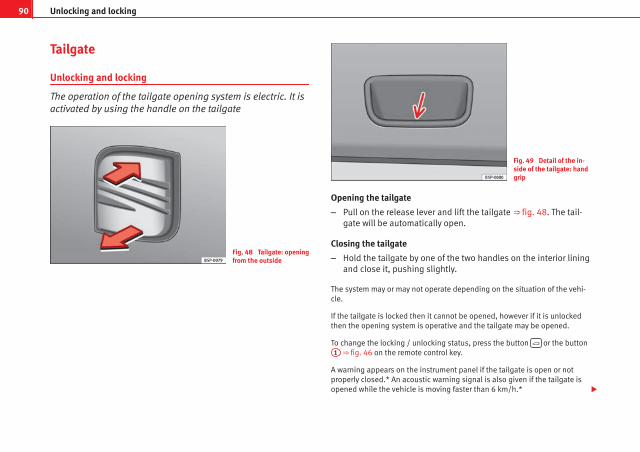
90 Unlocking and locking
Tailgate
Unlocking and locking
The operation of the tailgate opening system is electric. It isactivated by using the handle on the tailgate
Fig. 48 Tailgate: openingfrom the outside
Fig. 49 Detail of the in-side of the tailgate: handgrip
Opening the tailgate
– Pull on the release lever and lift the tailgate ⇒ fig. 48. The tail-gate will be automatically open.
Closing the tailgate
– Hold the tailgate by one of the two handles on the interior liningand close it, pushing slightly.
The system may or may not operate depending on the situation of the vehi-cle.
If the tailgate is locked then it cannot be opened, however if it is unlockedthen the opening system is operative and the tailgate may be opened.
To change the locking / unlocking status, press the button or the button1 ⇒ fig. 46 on the remote control key.
A warning appears on the instrument panel if the tailgate is open or notproperly closed.* An acoustic warning signal is also given if the tailgate isopened while the vehicle is moving faster than 6 km/h.*

91Unlocking and locking
WARNING
● Always close the tailgate properly. Risk of accident or injury.
● The tailgate must not be opened when the reverse or rear fog lightsare lit. This may damage the tail lights
● Do not close the tailgate by pushing it down with your hand on therear window. The glass could smash. Risk of injury!
● Ensure the tailgate is locked after closing it. If not, it may open unex-pectedly while driving.
● Never allow children to play in or around the vehicle. A locked vehiclecan be subjected to extremely high and low temperatures, depending onthe time of year, thus causing serious injuries/illness. It could even havefatal consequences. Close and lock both the tailgate and all the otherdoors when you are not using the vehicle.
● Closing the tailgate without observing and ensuring it is clear couldcause serious injury to you and to third parties. Make sure that no one isin the path of the tailgate.
● Never drive with the tailgate open or half-closed, exhaust gases maypenetrate into the interior of the vehicle. Danger of poisoning!
● If you only open the tailgate, do not leave the key inside. The vehiclewill not be opened if the key is left inside.
Emergency opening
This allows the vehicle to be opened if the central lockingdoes not operate (for example, if the battery is flat)
Fig. 50 Tailgate: emer-gency open
There is a groove in the luggage compartment allowing access tothe emergency opening mechanism.
Opening the tailgate from inside the luggage compartment
– Insert the key in the groove and unlock the locking system, turn-ing the key from right to left, as shown by the arrow ⇒ fig. 50.
Safety First Operating Instructions Practical Tips Technical Specifications

92 Unlocking and locking
Windows
Opening or closing the windows electrically*
The front and rear electric windows can be operated by us-ing the controls on the driver door. The other doors eachhave a switch for their own window.
Fig. 51 Detail of thedriver door: controls forthe front and rear win-dows
Opening and closing the windows
– Press the button to open the window.
– Pull button to close the window ⇒ .
Always close the windows fully if you park the vehicle or leave it unattended⇒ .
You can use the electric windows for approx. 10 minutes after switching offthe ignition if neither the driver door nor the front passenger door has beenopened and the key has not been removed from the ignition.
Buttons on the driver door
Button for window in front left door
Button for window in front right door
Safety switch for deactivating the electric window buttons in the reardoors
Button for window in rear left door
Button for window in rear right door
Safety switch *
Safety switch 3 on the driver door can be used to disable the electric win-dow buttons in the rear doors.
Safety switch not pressed: buttons on rear doors are activated.
Safety switch pressed: buttons on rear doors are deactivated.
WARNING
● Incorrect use of the electric windows can result in injury.
● Never close the tailgate without observing and ensuring it is clear, todo otherwise could cause serious injury to you and third parties. Makesure that no one is in the path of a window.
● Always take the vehicle key with you when you leave the vehicle.
● Never leave children or disabled persons in the vehicle, particularly ifthey have access to the keys. The misuse of the keys, for example, bychildren, may result in serious injury and accident.
● The engine may accidentally be started and be out of control.
● If the ignition is switched on, the electric equipment could be activa-ted with risk of injury, for example, in the electric windows.
● The doors can be locked using the remote control key. This couldmake the aid difficult in an emergency situation.
● Always take the key with you when you leave the vehicle.
1
2
3
4
5

93Unlocking and locking
WARNING (Continued)
● The electric windows will work until the ignition has been switchedoff and one of the front doors has been opened.
● If necessary, use the safety switch to disable the rear electric win-dows. Make sure that they have been disabled.
NoteIf the window is not able to close because it is stiff or because of an ob-struction, the window will automatically open again ⇒ page 93. If thishappens, check why the window could not be closed before attempting toclose it again.
One-touch opening and closing*
One-touch opening and closing means you do not have tohold down the button.
Buttons ⇒ fig. 51 1 , 2 , 4 and 5 have two positions for open-ing windows and two for closing them. This makes it easier to openand close windows to the desired position.
One-touch closing
– Pull up the window button briefly up to the second position. Thewindow closes fully.
One-touch opening
– Push down the window button briefly up to the second position.The window opens fully.
Restoring one-touch opening and closing
– The automatic open and close function will not work if the bat-tery has been temporarily disconnected. The function can be re-stored as follows:
– Close the window as far as it will go by lifting and holding thewindow switch.
– Release the switch and then lift it again for one second. Thiswill re-enable the automatic function.
If you push (or pull) a button to the first stage, the window will open (orclose) until you release the button. If you push or lift the button briefly tothe second stage, the window will open (one-touch opening) or close (one-touch closing) automatically. If you operate the button while the window isopening or closing, it stops at this position.
The one-touch opening and closing function will not function once the igni-tion has been switched off.
The one-touch function and roll-back function will not work if there is a mal-function in the electric windows. Contact an Authorised Service Centre.
Roll-back function
The roll-back function reduces the risk of injury when theelectric windows close.
● If a window is obstructed when closing automatically, the window stopsat this point and lowers immediately ⇒ .
● Next, check why the window does not close before attempting it again.
● If you try within the following 10 seconds and the window closes againwith difficulty or there is an obstruction, the automatic closing will stopworking for 10 seconds.
Safety First Operating Instructions Practical Tips Technical Specifications

94 Unlocking and locking
● If the window is still obstructed, the window will stop at this point.
● If there is no obvious reason why the window cannot be closed, try toclose it again by pulling the tab within ten seconds. The window closes withmaximum force. The roll-back function is now deactivated.
If more than 10 seconds pass, the window will open fully when you operateone of the buttons. One-touch closing is reactivated.
The one-touch function and roll-back function will not work if there is a mal-function in the electric windows. Contact an Authorised Service Centre.
WARNING
● Incorrect use of the electric windows can result in injury.
● Always take the key with you when leaving the vehicle, even if youonly intend to be gone for a short time. Please ensure that children arenever left alone inside the vehicle.
● The electric windows will work until the ignition has been switchedoff and one of the front doors has been opened.
● Closing the windows without observing and ensuring it is clear couldcause serious injury to you and third parties. Make sure that no one is inthe path of a window.
● Never allow people to remain in the vehicle when you close the vehi-cle from the outside. The windows cannot be opened even in an emergen-cy.
● The roll-back function does not prevent fingers or other parts of thebody from getting pinched against the window frame, causing injury.
Convenience opening and closing*
Using the door lock*
– Hold the key in the door lock of the driver door in either thelocking or the unlocking position until all windows are eitheropened or closed.
– Release the key to interrupt this function.
Using the remote control
– Keep the locking/unlocking button pressed for the electricalwindow risers to open/close; if you stop pressing the button,the window raising/lowering function is stopped.
– If the automatic raising is stopped and immediately after, theopening button is kept pressed, the window risers will lower.
– Once the windows are completely closed, the turn signals willflash.

95Unlocking and locking
Panorama tilting sunroof*
Opening and closing the panorama/tilting sunroof
The panorama/tilting sunroof is opened and closed by usingthe switch when the ignition is switched on.
Fig. 52 Panorama/tiltingsunroof
Closing the panorama/tilting sunroof
– Press and hold button B ⇒ fig. 52 ⇒ . The roof starts to closeuntil the button is released.
Opening the panorama/tilting sunroof
– Press and hold down button A . The roof starts opening untilthe button is released.
Automatic closing of the panorama/tilting sunroof
– Press button B once only; the sunroof starts closing automati-cally until it is completely closed.
Automatic opening of the panorama/ tilting sunroof
– Press button A once only. The sunroof starts opening automat-ically until it is completely open.
Restoring one-touch opening and closing
– Close the sunroof manually until it is completely closed. Re-lease the button
– Press the closing button again, keeping it pressed down, until acomplete opening and closing cycle has taken place.
Always close the panorama/tilting sunroof fully if you park the vehicle orleave it unattended ⇒ .
The tilting sunroof can be operated for up to about ten minutes after the ig-nition has been switched off, provided the driver door and the front passen-ger door are not opened.
Sun visor
The sun visor is opened and closed manually (independently of the sliding/tilting sunroof).
WARNING
● Incorrect use of the tilting sunroof can result in injury.
● Never close the tilting sunroof without first checking that there are noobstructions. Risk of serious injury to you or others. Make sure that noone is in the path of the tilting sunroof.
● Always take the vehicle key with you when you leave the vehicle.
● Never leave children or disabled persons in the vehicle, particularly ifthey have access to the keys. Unsupervised use of a key could mean thatthe engine is started or that electrical equipment is used (e.g. electric
Safety First Operating Instructions Practical Tips Technical Specifications

96 Unlocking and locking
WARNING (Continued)
tilting sunroof) with a risk of accident. The doors can be locked using theremote control key. This could make the aid difficult in an emergency sit-uation.
● The tilting sunroof continues to function until one of the front doors isopened and the key removed from the ignition.
● Ensure that no object and/or end is between the glass and the sun-roof when the one-touch opening/closing function is reset.
Convenience closing*
Using the door lock
– Hold the key in the door lock of the driver door in the lockingposition until the tilting sunroof is closed.
– Release the key to interrupt this function.
Using the remote control
– Push the lock button on the remote control for about 3 seconds.The tilting sunroof closes.
– Press the unlock button to interrupt the function.
Roll-back function of the panorama/ tilting sunroof*
The panorama/ tilting sunroof has a roll-back function which prevents largerobjects getting trapped when the roof is closed. The roll-back function doesnot prevent fingers getting pinched against the roof opening. The tiltingsunroof stops and opens again immediately if it is obstructed when closing.
Operation in case of breakdown
In case of a breakdown, the sunroof may be closed manual-ly.
Fig. 53 Emergency oper-ation of the panorama/tilting sunroof
– Remove the plastic cover by inserting a screwdriver into the rearsection.
– Insert an Allen key (4 mm) into the opening as far as possibleand close the sunroof.

97Lights and visibility
Lights and visibility
Lights
Switching lights on and off
Fig. 54 Detailed view ofthe dash panel: lights,fog lights and rear foglight switch
Switching on the side lights
– Turn the light switch ⇒ fig. 54 to position .
Switching on dipped beam headlights
– Turn the light switch to position .
Switching off the lights
– Turn the light switch to position 0.
Switching on the front fog lights*
– Turn the switch from position or to the first stop and pullit. The symbol in the light switch lights up.
Switching on the rear fog light (vehicles with front fog lights)
– Turn the lights control from position or to the second stopand pull out ⇒ . A warning lamp on the instrument panellights up.
Switching on the rear fog light (vehicles with no front fog lights)
– Turn the light control to the end from position or and pullit. A warning lamp on the instrument panel lights up.
WARNING
Never drive with just the side lights on. Risk of accident. The side lightsare not bright enough to illuminate the road ahead and to ensure thatother road users are able to see you. Always use your dipped beam head-lights if it is dark or if visibility is poor.
Note● The dipped beam headlights will only work with the ignition on. The sidelights come on automatically when the ignition is turned off.
● If the lights are left on after the key has been taken out of the ignitionlock, a buzzer will sound while the driver door remains open. This is a re-minder to switch the lights off.
Safety First Operating Instructions Practical Tips Technical Specifications

98 Lights and visibility
● The rear fog light is so bright that it can dazzle drivers behind you. Youshould use the rear fog light only when visibility is very poor.
● The use of the lighting described here is subject to the relevant statutoryrequirements.
Automatic lighting*
Fig. 55 Automatic light-ing
Activation
– Rotate the switch to the position “Auto”, this indication willlight up.
Deactivation
– Turn the light switch to 0.
Automatic lighting
If automatic headlight control is switched on, dipped beam headlights areautomatically switched on by a photosensor if you drive into a tunnel, forexample.
WARNING
● Even if the automatic headlight control is switched on, the dippedheadlights will not be switched on with fog. Therefore, the dipped beammust be switched on manually.
Note● For those vehicles with the automatic headlight system, when the key isremoved from the ignition, the acoustic signal will only sound if the lightknob is in position or .
● If the daylight driving automatic light function is switched on, the foglights or rear fog light cannot be switched on in addition.
● The use of the lighting described here is subject to the relevant statutoryrequirements.
● Do not put stickers on the windscreen in front of the sensor. This maycause disruptions or faults in the automatic lighting system.
● The rain sensor switches on the dipped beam headlights when the wind-screen wipers have been operating continuously for a few seconds and itswitches the lights off when the continuous or interval wipe is switched offfor some minutes.

99Lights and visibility
Instrument and switch lighting / Headlight range control
Fig. 56 Dash panel: reg-ulation for instrumentand switch illuminationand headlight range con-trol
Instrument and switch lighting 1
When the headlights are switched on, the brightness of the instrumentsand switch lighting can be regulated to suit your requirements by turningthe thumb wheel ⇒ fig. 56 1 .
Those vehicles fitted with xenon gas discharge headlights are fitted with anautomatic headlight range system.
Headlight range control 2
By using the electrical headlight range control, 2 you can adjust the head-light range to the load level that is being carried in the vehicle. This way, itis possible to avoid dazzling oncoming traffic more than necessary. At thesame time, by using the correct headlight settings, the driver has the bestpossible lighting for the road ahead.
The headlights can only be adjusted when the dipped beam is switched on.To lower the beam, turn the thumb wheel down 2 from the basic setting 0.
Dynamic headlight range control
Vehicles with gas discharge bulbs (xenon bulbs) are equipped with dynamicheadlight range control. When you switch on the lights, their range regu-lates itself according to the vehicle load.
Vehicles with gas discharge bulbs do not have headlight range control.
Daytime running lights*
Daytime running lights light up automatically when the igni-tion is switched on (only with AFS headlights)
Daylight driving lights switch off automatically when the street lightingcomes on.
Activating daytime lights (bi-xenon lamps)
Remove the key from the ignition, move the turn signal lever upwards (rightturn signal), press it backwards to flash position and hold in this position.Insert the key and switch the ignition on, holding it in this position for 3seconds. Then, switch off the ignition. The daytime lights are activated andcan be switched on.
Switching daytime lights off (bi-xenon lamps)
Remove the key from the ignition, move the turn signal lever upwards (leftturn signal), press it backwards to flash position and hold in this position.Insert the key and switch the ignition on, holding it in this position for 3seconds. Then, switch off the ignition. The daytime lights are deactivatedand cannot be switched on.
NoteSee legal requirements for each country.
Safety First Operating Instructions Practical Tips Technical Specifications

100 Lights and visibility
Adaptive headlights* (for driving round bends)
When driving around bends, the headlights will light themost important areas of the road.
Fig. 57 Cornering light-ing using adaptive head-lights
This cornering light gives better illumination of the side of the road and thecorner area. The dynamic lighting is controlled automatically according tospeed and the steering wheel angle.
The two main headlights move at different angles to avoid that the front ofthe vehicle is left completely in the dark.
NoteThe system operates from a speed of about 10 km/h.
Fog lights with cornering function*
This is an additional light source to dipped beam headlightsto light up the road as a bend is taken.
The cornering light operates with the lights switched on and when driving atless than 40 Km/h. They light up when the steering wheel is turned or theflashers are operated.
Forward gear
● If the steering wheel is turned to the right, or the right-hand turn signaloperated, the right-hand headlight lights up.
● If the steering wheel is turned to the left, or the left-hand flasher operat-ed, the left-hand headlight lights up.
In reverse gear both headlights light up.
NoteWhen the fog lamps are on, the cornering function is activated and bothheadlights are continuously on.
Coming/leaving Home function*
The Coming Home function is controlled manually. The Leav-ing Home function is controlled with a photosensor.
If the Coming Home or Leaving Home function is connected, the front sideand dipped lights, the tail lights and the number plate light will light up toprovide assistance.
Coming home function
The Coming Home function is activated by switching off the ignition andbriefly flashing the lights. When the driver door is opened, the Coming

101Lights and visibility
Home lighting comes on. If the driver door is already open when the lightsare flashed briefly, the Coming Home lighting comes on immediately.
When the last door of the vehicle or the tailgate is closed, the Coming Homefunction starts and the switching off the headlights is delayed.
The Coming Home lighting switches off in the following cases:
● On completion of the time period established for the delay in switchingoff the lights after all the vehicle doors and the tailgate have been closed.
● If, 30 seconds after being connected, any doors or the tailgate remainopen.
● If the light switch is turned to position .
● If the ignition is switched on.
Leaving home function
The Leaving Home function is activated when the vehicle is unlocked if:
● the light control is in position and
● the photosensor detects “darkness”.
The Leaving Home lighting switches off in the following cases:
● If the time period for the delay in switching off the headlights has ended
● If the vehicle is locked again.
● If the light switch is turned to position .
● If the ignition is switched on.
Note● To activate the coming/leaving home function, the rotary light switchmust be in position and the light sensor must detect darkness.
● If the ignition key is removed while the lights are on, and the lights areflashed briefly and the driver door opened, no acoustic signal is heard, aswhen the Coming Home function is on, the lights are automatically switchedoff after a period of time (except when the light switch is in position or.
Rear window heating
Fig. 58 Centre console:heated rear windowswitch
The heated rear window only works when the engine is running. When it isswitched on, a lamp lights up on the switch.
After approx. 8 minutes, the heating device of the rear window switches offautomatically.
Safety First Operating Instructions Practical Tips Technical Specifications

102 Lights and visibility
For the sake of the environmentThe heated rear window should be disconnected as soon as the glass isdemisted. By saving electrical power you can also save fuel.
NoteTo avoid possible damage to the battery, an automatic temporary discon-nection of this function is possible, coming back on when normal operatingconditions are re-established.
Hazard warning lights
The hazard warning lights are used to draw the attention ofother road users to your vehicle in emergencies.
Fig. 59 Centre console:switch for hazard warn-ing lights
If your vehicle breaks down:
1. Park your vehicle at a safe distance from moving traffic.
2. Press the button to switch on the hazard warning lights ⇒ .
3. Switch the engine off.
4. Apply the handbrake.
5. On a manual gearbox engage 1st gear. On an automatic, movethe selector lever to P.
6. Use the warning triangle to draw the attention of other roadusers to your vehicle.
7. Always take the vehicle key with you when you leave the vehi-cle.
Switch on the hazard warning lights to warn other road users, for examplewhen:
● reaching the tail end of a traffic jam,
● there is an emergency
● your vehicle breaks down due to a technical fault,
● you are towing another vehicle or your vehicle is being towed.
All turn signals flash simultaneously when the hazard warning lights areswitched on. That is that the two turn signal turn signal lamps and theturn signal lamp in the switch will flash at the same time. The hazardwarning lights also work when the ignition is switched off.
WARNING
● The risk of an accident increases if your vehicle breaks down. Alwaysuse the hazard warning lights and a warning triangle to draw the atten-tion of other road users to your stationary vehicle.
● Never park where the catalytic converter could come into contact withinflammable materials under the vehicle, for example dry grass or spiltpetrol. This could start a fire!

103Lights and visibility
Note● The battery will run down if the hazard warning lights are left on for along time, even if the ignition is switched off.
● The use of the hazard warning lights described here is subject to the rel-evant statutory requirements.
Turn signal and main beam headlight lever
The turn signal and main beam lever also operates the park-ing lights and the headlight flasher.
Fig. 60 Turn signal andmain beam headlight lev-er
The turn signal and main beam headlight lever has the followingfunctions:
Switching on the turn signals
– Move the lever all the way up ⇒ fig. 60 1 to indicate right, andall the way down 2 to indicate left.
Signalling a lane change
– Push the lever up 1 or down 2 to the point where you incurresistance and then release it. The turn signal will flash severaltimes. The corresponding warning lamp will also flash.
Switching main beam on and off
– Turn the light switch to position .
– Press the lever forward ⇒ fig. 60 4 to switch on the mainbeams.
– Pull the lever back towards you to switch the main beam head-lights off again.
Headlight flashers
– Pull the lever towards the steering wheel 3 to operate theflasher.
Switching on parking lights
– Switch the ignition off and remove the key from the lock.
– Move the lever up or down to turn the right or left-hand parkinglights on, respectively.
WARNING
The main beam can dazzle other drivers. Risk of accident! Never use themain beam headlights or the headlight flasher if they could dazzle otherdrivers.
Safety First Operating Instructions Practical Tips Technical Specifications

104 Lights and visibility
Note● The turn signals only work when the ignition is switched on. The corre-sponding warning lamp or flashes in the instrument panel. The warn-ing lamp flashes when the turn signals are operated, provided a trailer iscorrectly attached and connected to the vehicle. If a turn signal bulb is de-fective, the warning lamp flashes at double speed. If the trailer turn signalbulbs are damaged, warning lamp does not light up. Change the bulb.
● The main beam headlights can only be switched on if the dipped beamheadlights are already on. The warning lamp then comes on in the instru-ment panel.
● The headlight flasher comes on for as long as you pull the lever – even ifno other lights are switched on. The warning lamp then comes on in theinstrument panel.
● When the parking lights are switched on, the headlight and the tail lighton the corresponding side of the vehicle light up. The parking lights will on-ly work if the key is removed from the ignition. If the lights are switched on,an acoustic signal will be emitted while the driver door is open.
● If the turn signal lever is left on after the key has been taken out of theignition lock, an acoustic signal sounds when the driver door is opened.This is a reminder to switch off the turn signal, unless of course you wish toleave the parking light on.
Interior lights
Front interior light
Fig. 61 Interior roof trim:front interior lights
The switch A ⇒ fig. 61 is used to select the following positions:
Courtesy light position
Sliding switch in central position The interior lights are automaticallyswitched on when the vehicle is unlocked or the key removed from the igni-tion. And turn off approx. 20 seconds after closing the doors. The interiorlights are switched off when the vehicle is locked or when the ignition isswitched on.
Interior light switched on
Move the knob to the position .
Interior light switched off O
Move the switch to position O ⇒ fig. 61.

105Lights and visibility
NoteIf not all the vehicle doors are closed, the interior lights will be switched offafter approx. 10 minutes, providing the key has been removed and the cour-tesy light position selected. This prevents the battery from discharging.
Front reading light*
Fig. 62 Front readinglight
Switching on the reading light
Press the corresponding button B ⇒ fig. 62 to switch on the reading light.
Switching the reading lights off
Press the corresponding button to switch the reading light off.
Luggage compartment light*
The light is activated when the tailgate is open, even when the ignition andlights are turned off. For this reason, ensure that the tailgate is alwaysclosed.
Glove compartment light
When opening the glove compartment on the passenger side, the glovecompartment light will automatically turn on and will turn off upon closure.
Visibility
Sun visors
Fig. 63 Sun visor on thedriver side
Safety First Operating Instructions Practical Tips Technical Specifications

106 Lights and visibility
The sun visors for the driver and the front passenger can be pulled out oftheir central supports and turned towards the doors in the direction of thearrow ⇒ fig. 63. Never pull them downwards.
The driver sun visor has compartments for cards, and the passenger sun vi-sor has a vanity mirror with a cover*.
NoteIncorrect use of the sun visors (e.g. pulling them downwards once they areopen) may result in broken hinges. This damage is not covered by the vehi-cle warranty.
Windscreen wipers
Front windscreen wipers
The windscreen wiper lever controls the windscreen wipersand the automatic wash and wipe.
Fig. 64 Windscreen wip-er and windscreen washlever
The windscreen wiper lever ⇒ fig. 64 has the following positions:
Switching off the wipers
– Move the lever to position 0 .
Intermittent wipe
– Move the lever up to position 1 .
– Move the control A to the left or right to set the length of theintervals. Control to the left: long intervals; control to the right:
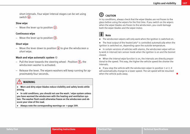
107Lights and visibility
short intervals. Four wiper interval stages can be set usingswitch A .
Slow wipe
– Move the lever up to position 2 .
Continuous wipe
– Move the lever up to position 3 .
Short wipe
– Move the lever down to position 4 to give the windscreen ashort wipe.
Wash and wipe automatic system
– Pull the lever towards the steering wheel - Position 5 , thewindscreen washer is activated.
– Release the lever. The wipers-washers will keep running for ap-proximately four seconds.
WARNING
● Worn and dirty wiper blades reduce visibility and safety levels whiledriving.
● In cold conditions, you should not use the wash / wipe system unlessyou have warmed the windscreen with the heating and ventilation sys-tem. The washer fluid could otherwise freeze on the windscreen and ob-scure your view of the road.
● Always note the corresponding warnings on ⇒ page 209.
CAUTIONIn icy conditions, always check that the wiper blades are not frozen to theglass before using the wipers for the first time. If you switch on the wiperswhen the wiper blades are frozen to the windscreen, you could damageboth the wiper blades and the wiper motor.
Note● The windscreen wipers will only work when the ignition is switched on.
● The heat output of the heated jets* is controlled automatically when theignition is switched on, depending upon the outside temperature.
● In certain versions of vehicles with alarms, the windscreen wiper will on-ly work in interval/rain sensor mode when the ignition is on and the bonnetclosed.
● When the interval wipe function is on, the intervals are directly propor-tional to the speed. This way, the higher the vehicle speed the shorter theintervals.
● If you stop the vehicle with the windscreen wiper in position 1 or 2, itwill automatically change to a lower speed. The set speed will be resumedwhen the vehicle pulls away.
Safety First Operating Instructions Practical Tips Technical Specifications

108 Lights and visibility
Rain sensor*
The rain sensor controls the frequency of the windscreenwiper intervals, depending on the amount of rain.
Fig. 65 Windscreen wip-er lever
Switching on the rain sensor
– Move the windscreen wiper lever into position 1 ⇒ fig. 65.
– Move the control A to the left or right to set the sensitivity ofthe rain sensor. Control to the right: highly sensitive. Control tothe left: less sensitive.
The rain sensor is part of the interval wipe function. You will have to switchthe rain sensor back on if you switch off the ignition. This is done by switch-ing the interval wipe function off and back on.
Note● Do not put stickers on the windscreen in front of the sensor. This maycause sensor disruption or faults.
Rear window wiper
The windscreen wiper lever operates the windscreen wiperand the wash and wipe system for the rear window.
Fig. 66 Windscreen wip-er and windscreen washlever: rear window wiper
Switching on the interval wipe
– Press the lever forwards to position 6 ⇒ fig. 66. The wiper willwipe the window approximately every 6 seconds.
Switching off the interval wipe function
– Pull the lever back from position 6 towards the steering wheel.The wiper will continue to function for a short period if youswitch off whilst the wipers are in motion.
Switching on the windscreen wiper and washer system
– Press the lever fully forwards to position 7 ⇒ fig. 66. The rearwiper and washer operate at the same time. The windscreenwash system will function as long as you hold the lever in thisposition.

109Lights and visibility
– Release the lever. The washer system stops and the wipers con-tinue until the end of the cycle.
– Move the lever towards the steering wheel to switch off.
WARNING
● A worn or dirty wiper blade will obstruct visibility and reduce safety.
● Always note the corresponding warnings on ⇒ page 209.
CAUTIONIn icy conditions, always check that the wiper blade is not frozen to theglass before using the wiper for the first time. If you switch on the wiperwhen the wiper blade is frozen to the glass, this could damage both thewiper blade and the wiper motor.
Note● The rear window wiper will only work when the ignition is switched on.
● Depending on the version of the model, when you engage reverse gearand with the headlight wiper activated, the lamps are wiped.
Headlight washer*
The headlight washers clean the headlight lenses.
The headlight washers are activated automatically when the windscreenwasher is used and the windscreen wiper lever is pulled towards the steer-ing wheel for at least 1.5 seconds – provided the dipped beam headlightsor main beams are switched on. Clean off stubborn dirt (insects, etc.) fromthe headlights at regular intervals, for instance when filling the fuel tank.
Note
● To ensure that the headlight washers work properly in winter, keep thenozzle holders in the bumper free of snow and remove any ice with a de-icerspray.
● To remove water, the windscreen wipers will be activated from time totime, the headlight wipers will be activated every three cycles.
Rear view mirrors
Adjusting the rear view mirrors
Before beginning any journey, adjust the rear view mirrors for correct visibil-ity.
Interior mirror
It is dangerous to drive if you cannot see clearly through therear window.
Manual anti-dazzle function for interior mirror
In the basic mirror position, the lever at the bottom edge of the mirrorshould be at the front. Pull the lever to the back to select the anti-dazzlefunction.
Safety First Operating Instructions Practical Tips Technical Specifications

110 Lights and visibility
Automatic anti-dazzle interior mirror*
The automatic anti-dazzle function can be switched on andoff as desired.
Fig. 67 Automatic anti-dazzle interior mirror.
Switching off the anti-dazzle function
– Press button A ⇒ fig. 67. Indicator lamp B goes off.
Switching on the anti-dazzle function
– Press button A ⇒ fig. 67. Warning lamp is lit.
Anti-dazzle function
The anti-dazzle function is activated every time the ignition is switched on.The green indicator lamp lights up in the mirror housing.
When the anti-dazzle function is enabled, the interior mirror will darken au-tomatically according to the amount of light it receives. The anti-dazzlefunction is cancelled if reverse gear is engaged.
Note● The automatic anti-dazzle function will only work properly if the sunblind* for the rear window is retracted and there are no other objects pre-venting light from reaching the rear view mirror.
● If you have to stick any type of sticker on the windscreen, do not do so infront of the sensors. Doing so could prevent the anti-dazzle function fromworking well or even from working at all.
Folding in the exterior mirrors
The exterior mirrors of the vehicle may be folded in. For this, press the mir-ror housing towards the vehicle.
NoteBefore washing the vehicle with an automatic car wash, fold in the mirrorsto avoid damage.

111Lights and visibility
Electric exterior mirrors*
The exterior mirrors can be adjusted using the rotary knobin the driver door.
Fig. 68 Controls of exte-rior mirrors
Basic setting of exterior mirrors
1. Turn knob ⇒ fig. 68 to position L (left exterior mirror).
2. Turn the rotary knob to position the mirror so that you have agood view to the rear of the vehicle.
3. Turn knob to position R (right exterior mirror).
4. Swivel the rotary knob to position the mirror so that you have agood view to the rear of the vehicle ⇒ .
Heated exterior mirrors*
– Press the demisting button ⇒ fig. 58
– The mirrors demist for some minutes to prevent draining thebattery.
– If necessary, press the button again to repeat the function.
– The exterior mirror heating is not activated with temperaturesabove 20 °C.
Folding in exterior mirrors*
– Turn the control ⇒ fig. 68 to position to fold in the exteriormirrors. You should always fold in the exterior mirrors if you aredriving through an automatic car wash. This will help preventdamage.
Folding exterior mirrors back out to the extended position*
– Turn the knob to position L or R to fold the exterior mirrors backout ⇒ .
WARNING
● Convex or aspheric mirrors increase the field of vision however theobjects appear smaller and further away in the mirrors. If you use thesemirrors to estimate the distance to vehicles behind you when changinglane, you could make a mistake. Risk of accident.
● If possible, use the rear view mirror to estimate distances to vehiclesbehind you.
● Make sure that you do not get your finger trapped between the mirrorand the mirror base when folding back the mirrors. Risk of injury!
For the sake of the environmentThe exterior mirror heating should be switched off when it is no longer nee-ded. Otherwise, it is an unnecessary fuel waste.
Safety First Operating Instructions Practical Tips Technical Specifications

112 Lights and visibility
Note● If the electrical adjustment ever fails to operate, the mirrors can be ad-justed by hand by lightly pressing the edge of the mirror glass.
● In vehicles with electric exterior mirrors, the following points should beobserved: if, due to an external force (e.g. a knock while manoeuvring), theadjustment of the mirror housing is altered, the mirror will have to be com-pletely folded electrically. Do not readjust the mirror housing by hand, asthis will interfere with the mirror adjuster function.
● The rear view mirrors can be adjusted separately or simultaneously, asdescribed before.
● The fold-in function on the exterior mirrors is not active at speeds over40 km/h.
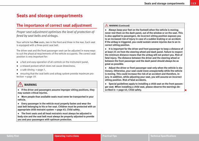
113Seats and storage compartments
Seats and storage compartments
The importance of correct seat adjustment
Proper seat adjustment optimises the level of protection of-fered by seat belts and airbags.
Your vehicle has five seats, two in the front and three in the rear. Each seatis equipped with a three-point seat belt.
The driver seat and the front passenger seat can be adjusted in many waysto suit the physical requirements of the vehicle occupants. The correct seatposition is very important for:
● a fast and easy operation of all controls on the instrument panel,
● a relaxed posture which does not cause drowsiness,
● a safe driving ⇒ page 7,
● ensuring that the seat belts and airbag system provide maximum pro-tection ⇒ page 19.
WARNING
● If the driver and passengers assume improper sitting positions, theymay sustain critical injuries.
● More people than available seats must never be transported in yourvehicle.
● Every passenger in the vehicle must properly fasten and wear theseat belt belonging to his or her seat. Children must be protected with anappropriate child restraint system ⇒ page 43, Child safety.
● The front seats and all head restraints must always be adjusted tobody size and the seat belt must always be properly adjusted to provideyou and your passengers with optimum protection.
WARNING (Continued)
● Always keep your feet on the footwell when the vehicle is moving;never rest them on the dash panel, out of the window or on the seat. Thisis also applied to passengers. An incorrect sitting position exposes youto an increased risk of injury in case of a sudden braking or an accident.If the airbag is triggered, you could sustain severe injuries due to an in-correct sitting position.
● It is important for the driver and front passenger to keep a distance ofat least 25 cm from the steering wheel and dash panel. Failure to respectthe minimum distance means that the airbag will not protect you. Risk offatal injury. The distance between the driver and the steering wheel orbetween the front passenger and the dash panel should always be asgreat as possible.
● Adjust the driver or front passenger seat only when the vehicle is sta-tionary. Otherwise, your seat could move unexpectedly while the vehicleis moving. This could increase the risk of an accident and therefore, in-jury. In addition, while adjusting your seat, you will assume an incorrectsitting position. Risk of fatal accidents.
● Special guidelines apply to installing a child seat on the front passen-ger seat. When installing a child seat, please observe the warnings de-scribed in ⇒ page 43, Child safety.
Safety First Operating Instructions Practical Tips Technical Specifications

114 Seats and storage compartments
Head restraints
Correct adjustment of head restraints
Properly adjusted head restraints are an important part ofpassenger protection and can reduce the risk of injuries inmost accident situations.
Fig. 69 Front view: headrestraints and seat beltscorrectly adjusted
Fig. 70 Side view: headrestraints and seat beltscorrectly adjusted
– Adjust the head restraint so that the top is at the same level asthe top of your head or as close as possible to the same level asthe top of your head, at least at eye level ⇒ fig. 69 and⇒ fig. 70.
Adjusting the head restraints ⇒ page 115
WARNING
● Travelling with the head restraints removed or improperly adjustedincreases the risk of severe injuries.
● Improperly adjusted head restraints could lead to death in the eventof a collision or accident.
● Incorrectly adjusted head restraints also increase the risk of injuryduring sudden or unexpected driving or braking manoeuvres.
● The head restraints must always be adjusted according to the pas-senger's height.

115Seats and storage compartments
Removing or adjusting head restraints
The head restraints can be adjusted by moving them up anddown.
Fig. 71 Adjusting and re-moving the head re-straints
Adjusting height (front seats)
– Press the button on the side and pull upwards to the desiredposition.
– To lower the head restraint, press the button and push head re-straint downwards.
– Make sure that it engages securely into position.
Adjusting height (rear seats)
– Press the button on the side and pull upwards to the desiredposition.
– To lower the head restraint, press the button and push head re-straint downwards.
– Make sure that the head restraint engages securely in one of itspositions ⇒ page 14.
Removing the head restraint
– Push the head restraint up as far as it will go.
– Press the button ⇒ fig. 71 (arrow).
– Pull head restraint out of fitting without releasing the button.
Fitting the head restraint
– Insert the head restraint into the guides on the backrest.
– Push head restraint down.
– Adjust the head restraint to suit body size ⇒ page 13.
WARNING
● Never drive if the head restraints have been removed. Risk of injury.
● Never drive if the head restraints are in an unsuitable position, thereis a risk of serious injury.
● After refitting the head restraint, you must always adjust it properlyfor height to achieve optimal protection.
● Please observe the safety warnings in ⇒ page 114, Correct adjust-ment of head restraints.
Note● To fit and remove the rear head restraints, gently tilt the seat backrestforwards.
● When fitting the head restraints again, insert the tubes as far as possi-ble into the guides without pressing the button.
Safety First Operating Instructions Practical Tips Technical Specifications

116 Seats and storage compartments
Front seats
Adjustment of the front seats
Fig. 72 Front left seatcontrols
1 Adjusting the seat forwards and backwards
– Pull up the grip and move the seat forwards or backwards.
– Then release the grip 1 and move the seat further until thecatch engages.
2 Adjusting seat height
– Pull the lever up or push down (several times if necessary) fromits home position. This adjusts the seat height in stages.
3 Adjusting the backrest angle
– Take your weight off the backrest and turn the hand wheel.
WARNING
● Never adjust the driver or front passenger seat while the vehicle is inmotion. While adjusting your seat, you will assume an incorrect sittingposition. Risk of fatal accidents. Adjust the driver or front passenger seatonly when the vehicle is stationary.
● To reduce the risk of injury to the driver and front passenger in case ofa sudden braking or an accident, never drive with the backrest tilted to-wards the rear. The maximum protection of the seat belt can be achievedonly when the backrests are in an upright position and the driver andfront passenger have properly adjusted their seat belts. The further thebackrests are tilted to the rear, the greater the risk of injury due to im-proper positioning of the belt web!
● Exercise caution when securing the seat height into forwards/back-wards position. Injuries can be caused if the seat height is adjusted with-out due care and attention.
● To move the seat lengthways, pull upwards and not sideways on thelever, as the force exerted on it in this position could damage it.

117Seats and storage compartments
Heated seats*
The front seat cushions and backrests can be heated electri-cally.
Fig. 73 Front seats heat-ing switch
– Press the corresponding switch ⇒ fig. 73 to switch on the seatheating.
– Press once to connect the heating at a maximum force. TwoLEDs will light up ⇒ fig. 73. After 15 min. of high intensity, theupper LED goes out, the system is deactivated for 2 min. and isthen reactivated at low intensity (lower LED remains on perma-nently).
– Press the switch again to set the heating to minimum force.(The lower LED lights up).
– To disconnect the heating, press the switch again.
CAUTIONTo avoid damaging the heating elements, please do not kneel on the seat orapply sharp pressure at a single point to the seat cushion and backrest.
NoteThe seats are only heated electrically when the engine is running.
Safety First Operating Instructions Practical Tips Technical Specifications

118 Seats and storage compartments
Rear seats
Folding down rear seats
Fig. 74 Folding up therear seat cushion
Fig. 75 Button for un-locking the rear backrest
Folding seat down
– Remove the head restraint ⇒ page 115.
– Pull the front edge of the seat cushion ⇒ fig. 74 1 upwards inthe direction of the arrow.
– Lift the cushion 2 forwards in the direction of the arrow.
– Pull the release button ⇒ fig. 75 in the direction of the arrowand fold the backrest forwards
– Insert the head restraints in the spaces on the rear of the seatcushion which are visible when the seat cushion is lowered.
Folding seat forward
– Remove the head restraints from the spaces in the seat cush-ion.
– Lift the backrest, before securing it, replace the head restraintsin the seat cushion, and then click the seat correctly onto thelocking rails.
– Once the backrest is locked, pull on the central seat belt or di-rectly on the backrest to check that the backrest has properlyengaged in position.
– Check that the position lever is in neutral position.
– Lower the cushion and push it backwards below the seat beltbuckles.
– Press the front part of the cushion downwards.

119Seats and storage compartments
On split rear seats1) the backrest and cushion can be lowered and raised re-spectively in two sections.
WARNING
● Please be careful when folding back the backrest! Injuries can becaused if the seat height is adjusted without due care and attention.
● Do no trap or damage seat belts when raising the backrest.
● After raising the backrest, check it has engaged properly in position.Do this by pulling on the central seat belt or directly on the backrest andcheck that the position lever is in the neutral position.
● The three point automatic seat belt only works correctly when thebackrest of the central seat is correctly engaged.
1) Optional equipment
Safety First Operating Instructions Practical Tips Technical Specifications

120 Seats and storage compartments
Storage compartment
Storage compartment on the front passenger side
Fig. 76 Passenger side:storage compartment
Fig. 77 Storage com-partment for instructionmanual
The compartment can be opened by pulling the lever ⇒ fig. 76.
This compartment can hold documents in A4 format, a water bottleof 1.5 L,...
WARNING
Always keep the storage compartment cover closed while the vehicle isin motion in order to reduce the risk of injury caused by a sudden brakingor by an accident.
Storage compartment on the driver side
There is an storage compartment on the driver side
Fig. 78 Driver side com-partment
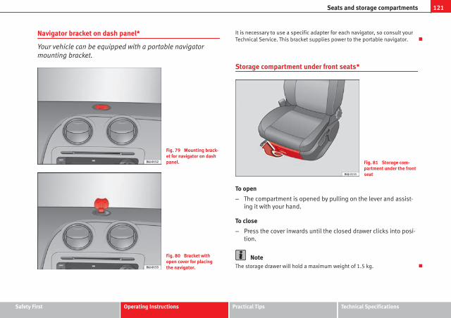
121Seats and storage compartments
Navigator bracket on dash panel*
Your vehicle can be equipped with a portable navigatormounting bracket.
Fig. 79 Mounting brack-et for navigator on dashpanel.
Fig. 80 Bracket withopen cover for placingthe navigator.
It is necessary to use a specific adapter for each navigator, so consult yourTechnical Service. This bracket supplies power to the portable navigator.
Storage compartment under front seats*
Fig. 81 Storage com-partment under the frontseat
To open
– The compartment is opened by pulling on the lever and assist-ing it with your hand.
To close
– Press the cover inwards until the closed drawer clicks into posi-tion.
NoteThe storage drawer will hold a maximum weight of 1.5 kg.
Safety First Operating Instructions Practical Tips Technical Specifications

122 Seats and storage compartments
Seat storage pocket*
Fig. 82 Seat storagepocket
There is a storage pocket on the rear of the front seats.
Storage compartment in the front door panel*
In this storage compartment a 1.5l water bottle can be stored,...
Front drink holder*
Fig. 83 Front cup hold-ers in the centre console
There are two cup holders in the centre console in front of the gear lever⇒ fig. 83.
WARNING
● Never place hot drinks in the drink holders. During normal or suddendriving manoeuvres, sudden braking or an accident, the hot drink couldbe spilled. Danger of scalding.
● Never use rigid materials (for example, glass or ceramic), these couldcause injury in the case of an accident.
● When travelling the drink holder should always be closed to preventrisk in the event of sudden breaking or accident.

123Seats and storage compartments
Rear drink holder*
Fig. 84 Cup holder in thecentre console
On the rear part of the centre console, behind the hand brake, there is a cupholder installed* ⇒ fig. 84.
This drink holder has a capacity of a bottle of up to 1 litre.
Ashtrays, cigarette lighter and power socket
Ashtray*
Fig. 85 Ashtray
Opening and closing the ashtray
– To open the ashtray, lift the cover ⇒ fig. 85.
– To close, push the cover down.
Emptying the ashtray
– Extract the ashtray and empty it.
WARNING
Never put paper in the ashtray. Hot ash could ignite the paper in the ash-tray and cause a fire.
Safety First Operating Instructions Practical Tips Technical Specifications

124 Seats and storage compartments
Cigarette lighter*
Fig. 86 Lighter
– Press on the cigarette lighter ⇒ fig. 86 to activate it ⇒ .
– Wait for the lighter to pop out slightly.
– Pull out the cigarette lighter and light the cigarette on the glow-ing coil.
WARNING
● Improper use of the cigarette lighter can lead to serious injuries orstart a fire.
● Using the lighter carefully. Carelessness or negligence when usingthe cigarette lighter can cause burns, risk of injury.
● The lighter only works when the ignition is turned on or the engine isrunning. To avoid the risk of fire, never leave children alone inside the ve-hicle.
Power socket
Fig. 87 Front powersocket
The 12 Volt cigarette lighter power socket can also be used for other electri-cal components with a power rating of up to 120 Watt. When the engine isswitched off, however, the vehicle battery will discharge. For further infor-mation see ⇒ page 189.
WARNING
The power sockets and the connected accessories will only operate whenthe ignition is on or when the engine is running. Improper use of thesockets or electrical accessories can lead to serious injuries or cause afire. To avoid the risk of injury, never leave children alone inside the vehi-cle.
Note● The use of electrical appliances with the engine switched off will cause abattery discharge.
● Before using any electrical accessories, see the instructions in⇒ page 189.

125Seats and storage compartments
Power socket in the luggage compartment*
Electrical equipment can be connected to the 12 volt socket.
Fig. 88 Detailed view ofthe side trim in the lug-gage compartment: 12volt socket
– Lift the power socket cover ⇒ fig. 88.
– Insert the plug of the electrical appliance into the socket.
Electrical equipment can be connected to the 12 volt socket. The appliancesconnected to the socket must not exceed a power rating of 100 W.
CAUTIONAlways use the correct type of plugs to avoid damaging the sockets.
Note● The power sockets will only work with the ignition on.
● The use of electrical appliances with the engine switched off will cause abattery discharge.
Auxiliary audio input connection (AUX)*
Fig. 89 AUX connectionon the central console(depending on the equip-ment)
– Lift the AUX cover ⇒ fig. 89.
– Insert the plug as far as possible (see radio manual).
Safety First Operating Instructions Practical Tips Technical Specifications

126 Seats and storage compartments
AUX/USB input connection*
Fig. 90 AUX/USB* inputconnection (dependingon the equipment)
For information concerning the use of this equipment, please see the Radiohandbook.
First-aid kit, warning triangle, fireextinguisher
Warning triangle*
Fig. 91 Housing for theemergency warning trian-gle in the luggage com-partment.
The warning triangle is under the storage compartment which is located un-der the luggage compartment floor.
Note● The warning triangle is not part of the vehicle's standard equipment.

127Seats and storage compartments
First-aid kit and fire extinguisher*
Fig. 92 Housing for thefirst-aid kit in the lug-gage compartment.
The first-aid kit can go in the storage compartment which is located underthe luggage compartment floor.
The fire extinguisher* is attached to the luggage compartment carpet withVelcro.
Note● The first-aid kit and the fire extinguisher are not part of the vehicle'sstandard equipment.
● The first aid kit must comply with legal requirements.
● Observe the expiry date of the contents of the first aid kit. After it hasexpired you should purchase a new one.
● The fire extinguisher must comply with legal requirements.
● Ensure that the fire extinguisher is fully functional. The fire extinguishershould, therefore, be checked regularly. The sticker on the fire extinguisherwill inform you of the next date for checking.
● Before acquiring accessories and emergency equipment see the instruc-tions in “Accessories and spares” ⇒ page 189.
Luggage compartment
Loading the luggage compartment
Loads in the luggage compartment should be safely se-cured.
Fig. 93 Position heavyitems as far forward aspossible.
To maintain safe handling on the road, please observe the follow-ing points:
– Distribute the load evenly.
Safety First Operating Instructions Practical Tips Technical Specifications

128 Seats and storage compartments
– Position heavy items as far forward as possible ⇒ fig. 93.
– Secure the load with a luggage net* or with non-elastic strapssecured to the fastening rings ⇒ page 128.
WARNING
● Unsecured objects in the luggage compartment can suddenly shiftand cause changes in the handling of the vehicle.
● In an accident or a sudden manoeuvre, loose objects in the passengercompartment can be flung forward and might injure vehicle occupants.
● Always keep all objects in the luggage compartment and use appro-priate grips to secure them, particularly in the case of heavy objects.
● When you transport heavy objects, always bear in mind that a changeof the centre of gravity can also cause changes in vehicle handling.
● Please refer to the notes on ⇒ page 7.
CAUTIONMake sure that no hard objects chafe against the wires of the heating ele-ment in the rear window and damage them.
NoteThe tyre pressure must be adjusted according to the load. When necessarycheck the tyre pressures on the label located on the inside fuel tank flap⇒ page 216.
Fastening rings*
There are four fastening rings in the luggage compartment,which can be used to secure loads.
Fig. 94 Location of fas-tening rings in luggagecompartment
– Use the fastening rings to secure the load ⇒ fig. 94 -arrows-.
– Please refer to the safety notes ⇒ page 17.

129Seats and storage compartments
Luggage net*
The luggage net can be used to secure and retain light itemsin the luggage compartment.
Fig. 95 Stretched lug-gage net
Luggage net
– Secure the luggage net to the four fastening rings -arrows-⇒ fig. 95.
The luggage net can be attached to the fastening rings in the bottom of theluggage compartment panel.
WARNING
The luggage net should only be used to hold objects weighing up to 5 kg.Heavier objects cannot be safely secured (risk of injury).
Rear shelf
Fig. 96 Rear shelf
Removing the shelf
– Unhook the loops ⇒ fig. 96 B from housings A
– With the half open position, pull the shelf upwards.
WARNING
Do not place heavy or hard objects on the rear shelf, because they willendanger the vehicle occupants in case of sudden braking.
CAUTION● Before closing the tailgate, ensure that the rear shelf is correctly fitted.
● An overloaded luggage compartment could mean that the rear shelf isnot correctly seated and it may be bent or damaged.
● If the luggage compartment is overloaded, remove the tray.
Safety First Operating Instructions Practical Tips Technical Specifications

130 Seats and storage compartments
Note● Ensure that, when placing items of clothing on the luggage compart-ment cover, rear visibility is not reduced.
Rear shelf with storage compartment*
Fig. 97 Removing stor-age compartment
Fig. 98 Accessing stor-age compartment
To remove the storage compartment
– Remove the rear shelf and pull the storage compartment up-wards holding it by the edges ⇒ fig. 97.
The storage compartment can be accessed from the rear seats by lifting thefront side of the rear shelf ⇒ fig. 98.
WARNING
Do not place heavy or hard objects on the rear shelf, because they willendanger the vehicle occupants in case of sudden braking.
CAUTION● Before closing the tailgate, ensure that the rear shelf is correctly fitted.
● An overloaded luggage compartment could mean that the rear shelf isnot correctly seated and it may be bent or damaged.
● If the luggage compartment is overloaded, remove the tray.
● The load in the storage compartment should not exceed 3 kg.
131Seats and storage compartments
Note● Ensure that, when placing items of clothing on the luggage compart-ment cover, rear visibility is not reduced.
● If your vehicle has a storage compartment*, only place light objects in-side.
Roof rack*
Please observe the following points if you intend to carry loads on the roof:
● For safety reasons, only luggage racks and accessories approved bySEAT should be used.
● It is essential that you follow the assembly instructions included withthe bars exactly, being especially careful to position the front and rear lug-gage compartment cover bars on the special housings on the longitudinalbars. You must also respect their position according to the direction of trav-el indicated in the assembly manual. Not following these instructions maycause marks on the longitudinal bars.
● Distribute the load evenly. A maximum load of 40 kg only is permittedfor each roof rack system support bar, the load must be distributed evenlyalong the entire length. However, the maximum load permitted for the en-tire roof (including the support system) of 75 kg must not be exceeded norshould the total weight of the vehicle be exceeded. See the Technical Datasection.
● When transporting heavy or large objects on the roof, any change in thenormal vehicle behaviour due to a change in the centre of gravity or an in-creased wind resistance must be taken into account. For this reason, a suit-able speed and driving style must be used.
● For those vehicles fitted with a sliding/tilting sunroof*, ensure that itdoes not interfere with the load on the roof rack system when opened.
Safety First Operating Instructions Practical Tips Technical Specifications

132 Air conditioning
Air conditioning
Heating
Controls
Fig. 99 Heating controlson the dash panel
– Using the controls A and C and with the switch B ⇒ fig. 99you can adjust the temperature, the air distribution and theblower speed.
– Press the button D to switch air recirculation mode on or off.When the function is activated, a warning light on the button isturned on.
Temperature
Switch A adjusts temperature. The required temperature inside the vehiclecannot be lower than the ambient temperature. Maximum heat output,
which is needed to defrost the windows quickly, is only available when theengine has reached its operating temperature.
Blower
The air flow can be set at four speeds with switch B . The blower should al-ways be set at the lowest speed when driving slowly.
Air distribution
Control C for setting the flow of air in the required direction.
– Air distribution towards the windscreen in order to demist. For safetyreasons, it is not recommended to switch air recirculation on.
– Air distribution to the upper body
– Air distribution to footwell
– Air distribution to the windscreen and the footwell.
Air recirculation mode
Air recirculation mode D on (a lamp lights up in red) prevents strongodours from the outside air from entering in the vehicle, for example whenpassing through a tunnel or in a traffic jam ⇒ .
When the outside temperature is low, air recirculation mode improves heat-ing performance by heating air from the interior instead of cold air from theoutside.

133Air conditioning
WARNING
● For your safety, the windows should never be fogged up or coveredwith snow or ice. This is essential to ensure good visibility. Please famili-arise yourself with the correct operation of the heating and ventilationsystem, including the demist/defrost functions for the windows.
● In air recirculation mode, no cold air from the outside enters the vehi-cle interior. The windows can quickly fog over if the heating is switchedoff. Therefore, never leave the air recirculation mode switched on for along time (risk of accident).
Note● Please consider the general notes ⇒ page 140.
Vehicle ventilation or heating
Fig. 100 Heating con-trols on the dash panel
Ventilating the passenger compartment
– Turn the temperature selector A ⇒ fig. 100 anti-clockwise.
– Turn blower switch B to any of the head settings 1 -4.
– Set the airflow to the desired direction using air distributioncontrol C .
– Open the relevant air outlets.
Interior heating
– Turn the temperature selector A ⇒ fig. 100 clockwise to selectthe desired temperature.
– Turn blower switch B to any of the head settings 1-4.
– Set the airflow to the desired direction using air distributioncontrol C .
– Open the relevant air outlets.
Defrosting the windscreen
– Turn the temperature selector A ⇒ fig. 100 clockwise to reachthe maximum temperature.
– Turn the blower switch B to setting 4.
– Turn air distribution control to .
– Close outlet 3 .
– Open and turn outlet 4 towards side windows
Keeping the windscreen and the side windows demisted
– Turn the temperature selector A ⇒ fig. 100 to the heating area.
Safety First Operating Instructions Practical Tips Technical Specifications

134 Air conditioning
– Turn blower switch B to any of the head settings 2 -3.
– Turn air distribution control to .
– Close outlets 3
– Open and turn outlets 4 towards side windows
Once the windows are demisted and as a preventive measure, the controlC can be set in position , thus obtaining greater comfort while prevent-
ing the windows from misting again.
Heating
Maximum heat output, which is needed to defrost the windows quickly, isonly available when the engine has reached its operating temperature.
NoteRemember that the temperature of the engine coolant should be optimumto ensure that the heating system functions correctly (except in vehicles fit-ted with additional heating*)
Air outlets
Fig. 101 Air vent

135Air conditioning
Air distribution C
Switch on symbol Main air output through outlets:
1,2
5
1, 2, 5
3, 4
Outlets 3 and 4 can be closed or opened separately and the air flow di-rected as required.
Air conditioning*
Controls
Fig. 102 Air condition-ing controls on the dashpanel
The air conditioning system only works when the engine is runningand the fan is switched on.
– Using the controls ⇒ fig. 102 A and C and with the switch B
you can adjust the temperature, the air distribution and theblower speed.
– To switch a function on or off, press the appropriate button D
or E . When the function is activated, a red warning light on thebutton is turned on.
– To demist the wind screens:
– Turn air distribution to
– Turn the fan control to one of the two levels depending on thespeed required.
– Rotate the temperature control to the desired level of comfort.
– Close outlets 3
– Open and turn outlets 4 towards side windows
Temperature selector ⇒ page 136
Blower control. There are four speed settings for the blower. At lowspeed, it is recommended to set the blower to a minimum of 1 to im-prove the intake of fresh air.
Air distribution control ⇒ page 136
Air recirculation button ⇒ page 137
AC button – Switch on air conditioning ⇒ page 136
A
B
C
D
E
Safety First Operating Instructions Practical Tips Technical Specifications

136 Air conditioning
WARNING
For your safety, the windows should never be fogged up or covered withsnow or ice. This is essential to ensure good visibility. Please familiariseyourself with the correct operation of the heating and ventilation system,including the demist/defrost functions for the windows.
NotePlease consider the general notes.
Vehicle interior heating or cooling system
Fig. 103 Air condition-ing controls on the dashpanel
Interior heating
– Disconnect the cooling system using button ⇒ fig. 103 AC (thebutton light turns off).
– Turn the temperature selector A to set the desired temperatureinside the vehicle.
– Turn the blower switch to any of the settings 1-4.
– Set the air distribution control C to the air flow configurationdesired: (towards the windscreen), (towards the chest), (towards the footwell) and (towards the windscreen and
footwell areas).
Interior cooling
– Connect the cooling system with button AC (the button lightshould light up).
– Turn the temperature control switch until the desired interiortemperature is reached.
– Turn the blower switch to any of the settings 1-4.
– Set the air distribution control to the air flow configuration de-sired: (towards the windscreen), (towards the chest), (towards the footwell) and (towards the windscreen andfootwell areas).
Heating
Maximum heat output, which is needed to defrost the windows quickly, isonly available when the engine has reached its operating temperature.
Coolant system
When the air conditioning is switched on, the temperature and the air hu-midity go down. This way, if the outside humidity is extreme, the air condi-tioning prevents the misting of the windows and therefore, comfort is im-proved.
If the air conditioning does not work, this may be due to the following rea-sons:

137Air conditioning
● The engine is stationary.
● The fan blower is switched off.
● The outside temperature is below +3 ℃.
● The cooling system compressor has been temporarily switched off be-cause of an increased engine coolant temperature.
● The air conditioner fuse is faulty.
● Another fault in the vehicle. Have the air conditioning checked by aqualified workshop.
Air recirculation
Air recirculation mode prevents fumes or unpleasant smellsfrom coming from the outside.
When air recirculation mode is switched on (button ⇒ fig. 103 with warn-ing lamp) strong odours in the outside air do not enter the vehicle interior,for example when passing through a tunnel or in a traffic jam.
When the outside temperature is low, air recirculation mode improves heat-ing performance by heating air from the interior instead of cold air from theoutside.
When the outside temperature is high, air recirculation mode improves cool-ing performance by cooling air from the interior instead of warm air fromoutside.
For safety reasons, the air recirculation should not be switched on when theair distribution control is set to the windscreen setting .
WARNING
In air recirculation mode, no cold air from the outside enters the vehicleinterior. If the air conditioner is switched off, the windows can quicklymist over. Therefore, never leave the air recirculation mode switched onfor a long time (risk of accident).
Note● When engaging reverse gear, the air recirculation is connected automat-ically to prevent the entrance of exhaust fumes in the vehicle on travellingbackwards. The warning lamp on the button does not light up.
● If the temperature control is turned to the coldest setting (blue point)and the switch AC is activated, the “Air recirculation” function is automati-cally activated in order to cool the vehicle rapidly using less energy; itsfunction indicator will light.
● If the function is not deactivated by pressing the button, this will deacti-vate after approx. 20 min.
Economic use of the air conditioning
When the air conditioning is switched on, the compressor consumes enginepower and has influence on fuel consumption. Consider the followingpoints in order to have the system operating in the minimum possible time.
● If the vehicle interior has overheated due to an excessive solar radiation,it is best to open the windows or doors to allow the hot air to escape.
● While in motion, the air conditioning should not be switched on if thewindows or the sunroof are open.*
Safety First Operating Instructions Practical Tips Technical Specifications

138 Air conditioning
Climatronic
Controls
Fig. 104 Climatronic controls on the dash panel
The air conditioner only works when the engine is running and theblower is switched on.
– Press keys 10 and 11 ⇒ fig. 104 to adjust temperature.
– The functions will be switched on when its buttons are pressed.When the function is activated, a symbol is displayed on thescreen. Press the button again to switch off the function.
Blower level indicator.
Air recirculation display:
Display AUTO (Automatic operation)
Demisting indicator
AC indicator (Cooling connected)
1
2
3
4
5
Interior temperature indicator selected
Air flow direction indicator
Fan speed increase
Fan speed decrease
Interior temperature increase
Interior temperature decrease
AUTO button – Automatic adjustment of temperature, ventilation andair distribution
Button – Windscreen demisting function. The air drawn in is direc-ted at the windscreen. The air recirculation mode will be switched off assoon as the demisting function is switched on. At temperatures over3 °C, the cooling system is switched on automatically in order to dry theair.
Button – Air distribution to head area
Button – Air distribution to the upper body.
Button – Air distribution to footwell
– Manual air recirculation
AC button – To switch on the air conditioning.
WARNING
For your safety, the windows should never be fogged up or covered withsnow or ice. This is essential to ensure good visibility. Please familiariseyourself with the correct operation of the heating and ventilation system,including the demist/defrost functions for the windows.
NotePlease consider the general notes.
6
7
8
9
10
11
12
13
14
15
16
17
18

139Air conditioning
Automatic mode
In automatic mode air temperature, air flow and distributionare automatically regulated so that a specified temperatureis attained as quickly as possible, and then maintained.
Switching on automatic mode
– Press the button AUTO . The indication ⇒ fig. 104 7 is visible.
– Press keys 10 and 11 ⇒ fig. 104 to adjust the desired tempera-ture inside the vehicle. We recommend 22 °C (72 °F).
A comfortable interior climate is quickly reached when a temperature of+22 °C (72 °F) is set in automatic mode. Therefore, we recommend you notto change this adjustment, except as necessary to suit individual preferen-ces or particular circumstances. It is possible to select interior temperaturesfrom +18 °C (64 °F) to +29 °C (86 °F). If a lower or higher temperature is se-lected, LO or HI are respectively displayed on the screen. These are approxi-mate temperatures which may slightly vary depending on the outside condi-tions.
Climatronic maintains a constant temperature. To do it, it automatically reg-ulates the supplied air temperature, the blower speed and the air distribu-tion. The system also considers the sunlight radiation, so there is no needfor manual readjustment. Therefore, automatic mode almost always pro-vides the best comfort for the vehicle occupants throughout the year.
Automatic mode is switched off whenever an adjustment is made using thebuttons for the air distribution, blower or AC . The temperature continues toself-regulate.
Manual mode
In manual mode the air temperature, flow, and the desiredair distribution can be adjusted.
Switching on manual mode
– Press one of the buttons ⇒ fig. 104 14 to 16 or press the blowercontrol 8 and 9 down. The indicator is switched off 3 .
Temperature
It is possible to select interior temperatures from +18 °C (64 °F) to +29 °C(86 °F). These are approximate temperatures which may slightly vary de-pending on the outside conditions.
If a temperature below 18 °C (64 °F) is selected, the screen will show LO. Inthis setting the system runs at maximum cooling output and the tempera-ture is not regulated.
If a temperature above 29 °C (86 °F) is selected, the screen will show HI. Inthis setting the system runs at maximum heating output and the tempera-ture is not controlled.
Blower
The blower can be adjusted with buttons 8 and 9 ⇒ fig. 104. If the bloweris off (level 1 is not shown on the screen) and button 9 is kept presseddown, the Climatronic switches off. Then OFF is displayed on the screen.
Air distribution
The air distribution is adjusted using the buttons , and . It is alsopossible to open and close some of the air outlets separately.
Switching the air conditioning on and off
Pressing the button AC the air cooling system can be switched off in orderto save fuel. The temperature continues to self-regulate. The set tempera-ture can then only be reached if it is higher than the outside temperature.
Safety First Operating Instructions Practical Tips Technical Specifications

140 Air conditioning
Air recirculation mode
Air recirculation mode prevents fumes or unpleasant smellsfrom coming from the outside.
– Press the button to switch air recirculation mode on or off.This is ON if the symbol ⇒ fig. 104 is displayed on thescreen.
Air recirculation mode prevents strong odours in the ambient air from enter-ing the vehicle interior, for example when passing through a tunnel or in atraffic jam.
When the outside temperature is low, air recirculation mode improves heat-ing performance by heating air from the interior instead of cold air from theoutside.
When the outside temperature is high, air recirculation mode improves cool-ing performance by cooling air from the interior instead of warm air fromoutside.
For safety reasons, the air recirculation should not be switched on when theair distribution control is set to the windscreen setting .
WARNING
In air recirculation mode, no cold air from the outside enters the vehicleinterior. If the air conditioner is switched off, the windows can quicklymist over. Therefore, never leave the air recirculation mode switched onfor a long time (risk of accident).
NoteWhen engaging reverse gear, the air recirculation is connected automatical-ly to prevent the entrance of exhaust fumes in the vehicle on travelling back-wards. In this case the symbol for air recirculation is not displayed.
General notes
Pollution filter
The pollution filter (a combined particulate filter and active carbon filter)serves as a barrier against impurities in the outside air, including dust andpollen.
For the air conditioner to work with maximum efficiency, the pollution filtermust be replaced at the specified intervals in the Maintenance Programme.
If the filter loses efficiency prematurely due to use in areas reaching veryhigh pollution levels, the pollen filter must be changed more frequentlythan stated in the Service Schedule.
CAUTION● If you suspect that the air conditioner is damaged, switch it off with but-ton AC to prevent further damage and have it checked by a specialisedworkshop.
● Repairs to the air conditioner require specialist knowledge and specialtools. Therefore, we recommend you to take the vehicle to a specialisedworkshop.
Note● If the humidity and temperature outside the vehicle are high, condensa-tion can drip off the evaporator in the cooling system and so forming a pud-dle underneath the vehicle. This is completely normal and there is no needto suspect a leak.
● Keep the air intake slots in front of the windscreen free of snow, ice andleaves to ensure heating and cooling are not impaired, and to prevent thewindows from misting over.
● The air from the vents flows through the vehicle interior and is extractedby slots designed for this purpose. Therefore, do not cover these slots withitems of clothing or other objects.

141Air conditioning
● The air conditioner operates most effectively with the windows and thesliding/tilting sunroof* closed. However, if the temperature inside the vehi-cle is excessive because of the sun, the air inside can be cooled faster byopening the windows for a short time.
● Do not smoke while air recirculation mode is on, as smoke drawn intothe air conditioning system leaves a residue on the evaporator, producing apermanent unpleasant odour.
● At low outside temperatures the compressor switches off automatically.The AUTO button cannot be switched on either.
● It is advisable to connect the air conditioning at least once a month, tolubricate the system gaskets and prevent leaks. If a decrease in the coolingcapacity is detected, an Authorised Service Centre should be consulted tocheck the system.
● To ensure correct operation, the grilles on both sides of the screen mustnot be obstructed
● When the engine is under extreme strain, switch off the compressor for amoment.
Safety First Operating Instructions Practical Tips Technical Specifications

142 Driving
Driving
Steering
Adjusting the steering wheel position
The height and reach of the steering wheel can be freely ad-justed to suit the driver.
Fig. 105 Steering col-umn height adjustment
– Adjust the driver seat to the correct position.
– Push the lever under the steering column ⇒ fig. 105 down ⇒ .
– Adjust the steering wheel until the correct position is set⇒ fig. 105.
– Then push the lever up again firmly ⇒ .
WARNING
● Incorrect use of the steering column adjustment function and an in-correct seating position can result in serious injury.
● To avoid accidents, the steering column should be adjusted onlywhen the vehicle is stationary.
● Adjust the driver seat or steering wheel so that there is a distance ofat least 25 cm between the steering wheel and your chest ⇒ fig. 105. Ifyou fail to observe the minimum distance, the airbag will not protect you.Risk of fatal injury.
● If your physical constitution does not allow you to maintain the mini-mum distance of 25 cm, contact an Authorised Service Centre. The Au-thorised Service Centre will help you to decide if special specific modifi-cations are necessary.
● If you adjust the steering wheel so that it points towards your face,the driver airbag will not protect you properly in the event of an accident.Make sure that the steering wheel points towards your chest.
● When driving, always hold the steering wheel with both hands on theoutside of the ring at the 9 o'clock and 3 o'clock positions. Never holdthe steering wheel at the 12 o'clock position, or in any other manner(e.g. in the centre of the steering wheel, or on the inside of the rim). Insuch cases, if the airbag is triggered, you may sustain injuries to thearms, hands and head.

143Driving
Safety
Electronic Stability Programme (ESP)*
ESP helps make driving safer in certain situations.
Fig. 106 Detailed view ofthe centre console: ESPbutton.
The Electronic Stability Programme (ESP) contains the electronic differentiallock (EDL) and the traction control system (TCS). The ESP function works to-gether with the ABS. Both warning lamps will light up if the ESP or ABS sys-tems are faulty.
The ESP is started automatically when the engine is started.
The ESP is always active, and cannot be switched off. With the ESP switch itis only possible to switch TCS off.
WARNING
● The Electronic Stability Programme (ESP) cannot defy the laws ofphysics. This should be kept in mind, particularly on slippery and wetroads and when towing a trailer.
● Always adapt your driving style to suit the condition of the roads andthe traffic situation. Do not let the extra safety afforded by ESP tempt youinto taking any risks when driving, as this can cause accidents.
● Please refer to the corresponding warning notes on ESP in⇒ page 167, Intelligent technology.
Ignition lock
Position of the ignition key
Fig. 107 Ignition key po-sitions
Safety First Operating Instructions Practical Tips Technical Specifications

144 Driving
Ignition switched off, steering lock 1
In this position ⇒ fig. 107 the ignition and the engine are OFF and the steer-ing may get locked.
For the Steering lock to operate without the ignition key, turn the steeringwheel until it locks with an audible sound. You should always lock the steer-ing wheel when you leave your vehicle. This will help prevent vehicle theft⇒ .
Switching the ignition or the glow plug system on 2
Turn the ignition key to this position and release it. If the key cannot beturned or it is difficult to turn from position 1 to position 2 , move thesteering wheel from one side to the other until it is released.
Starting 3
The engine is started when the key is in this position. Electrical componentswith a high power consumption are switched off temporarily.
Every time the vehicle is started again, the ignition key must be turned toposition 1 . The repetitive start prevention lock of the ignition preventspossible damage to the starter motor if the engine is already running.
WARNING
● The ignition key must NOT be removed from the lock until the vehiclecomes to a standstill. Otherwise, the steering could be immediatelyblocked- Risk of accident!
● Always remove the key from the ignition when leaving the vehicle,even for a short period. This is especially important if children or disa-bled people are left alone in the vehicle. They could accidentally start theengine or work electrical equipment such as the electric windows, conse-quently resulting in an accident.
● Unsupervised use of the keys could start the engine or any electricalsystem, such as the electric window. This could result in serious injury.
CAUTIONThe starter motor will only work when the engine is stopped (ignition keyposition 3 ).
Electronic immobiliser
The immobiliser prevents unauthorised persons from driv-ing the vehicle.
Inside the key there is a chip that deactivates the electronic immobiliser au-tomatically when the key is inserted into the ignition.
The immobiliser will be activated again automatically as soon as you pullthe key out of the ignition lock.
The engine can only be started using a genuine SEAT key with its correctcode.
NoteA perfect operation of the vehicle is ensured if genuine SEAT keys are used.

145Driving
Starting and stopping the engine
Starting petrol engines
The engine can only be started using a genuine SEAT keywith its correct code.
– Move the gear lever to the neutral position and depress theclutch pedal thoroughly and hold it in this position for the start-er to turn the engine on.
– Turn the ignition key to the starting position ⇒ page 143.
– Let go of the ignition key as soon as the engine starts; the start-er motor must not run on with the engine.
After starting a very hot engine, you may need to slightly press down the ac-celerator.
When starting a very cold engine, it may be a little noisy for the first few sec-onds until oil pressure has built up in the hydraulic valve compensators.This is quite normal, and no cause for concern.
If the engine does not start immediately, switch the starter off after 10 sec-onds and try again after half a minute. If the engine still does not start, thefuel pump fuse should be checked ⇒ page 229, Fuses.
WARNING
● Never start or run the engine in unventilated or closed rooms. The ex-haust fumes contain carbon monoxide, an odourless and colourless poi-sonous gas. Risk of fatal accidents. Carbon monoxide can cause loss ofconsciousness. It can also cause death.
● Never leave the vehicle unattended if the engine is running.
● Never use “cold start sprays”, they could explode or cause the engineto run at high revs. Risk of injury.
CAUTION● When the engine is cold, you should avoid high engine speeds, drivingat full throttle and over-loading the engine. Risk of engine damage.
● The vehicle should not be pushed or towed more than 50 metres to startthe engine. Unburnt fuel could enter the catalytic converter and damage it.
● Before attempting to push-start or tow a vehicle in order to start it, youshould first try to start it using the battery of another vehicle. Note and fol-low the instructions in ⇒ page 246, Jump-starting.
For the sake of the environmentDo not warm-up the engine by running the engine with the vehicle station-ary. Start off immediately, driving gently. This helps the engine reach oper-ating temperature faster and reduces emissions.
Safety First Operating Instructions Practical Tips Technical Specifications

146 Driving
Starting diesel engines
The engine can only be started using a genuine SEAT keywith its correct code.
– Move the gear lever to the neutral position and depress theclutch pedal thoroughly and hold it in this position for the start-er to turn the engine on.
– Turn the ignition key to the starting position.
– Turn the ignition key to position ⇒ fig. 107 2 . The indicatorlamp will light for engine pre-heating.
– When the warning lamp turns off, turn the key to position 3 tostart the engine. Do not press the accelerator.
– Let go of the ignition key as soon as the engine starts, the start-er motor must not be allowed to run on with the engine.
When starting a very cold engine, it may be a little noisy for the first few sec-onds until oil pressure has built up in the hydraulic valve compensators.This is quite normal, and no cause for concern.
If there are problems starting the engine, see the ⇒ page 246.
Glow plug system for the diesel engine
To avoid unnecessary discharging of the battery, do not use any other majorelectrical equipment while the glow plugs are pre-heating.
Start the engine as soon as the glow plug warning lamp goes out.
Starting the engine after the fuel tank has been completely run dry
If the fuel tank has been completely run dry, it may take longer than normal(up to one minute) to start the engine after refuelling with diesel fuel. This isbecause the system must eliminate air first.
WARNING
● Never start or run the engine in unventilated or closed rooms. The ex-haust fumes contain carbon monoxide, an odourless and colourless poi-sonous gas. Risk of fatal accidents. Carbon monoxide can cause loss ofconsciousness. It can also cause death.
● Never leave the vehicle unattended if the engine is running.
● Never use “cold start sprays”, they could explode or cause the engineto run at high revs. Risk of injury.
CAUTION● When the engine is cold, you should avoid high engine speeds, drivingat full throttle and over-loading the engine. Risk of engine damage.
● The vehicle should not be pushed or towed more than 50 metres to startthe engine. Unburnt fuel could enter the catalytic converter and damage it.
● Before attempting to push-start or tow a vehicle in order to start it, youshould first try to start it using the battery of another vehicle. Note and fol-low the instructions in ⇒ page 246, Jump-starting.
For the sake of the environmentDo not warm-up the engine by running the engine with the vehicle station-ary. You should drive off as soon as you start the engine. This helps the en-gine reach operating temperature faster and reduces emissions.
Switching off the engine
– Stop the vehicle.
– Turn the ignition key to position ⇒ fig. 107 1 .
After switching the engine off, the radiator fan may run on for up to 10 mi-nutes. It is also possible that the fan turns itself on once more if the coolant

147Driving
temperature increases due to the heat accumulated in the engine compart-ment or due to its prolonged exposure to solar radiation.
WARNING
● Never switch the engine off until the vehicle is completely stationary.
● The brake servo works only when the engine is running. With the en-gine switched off, more strength is needed to brake. As normal brake op-eration cannot be performed, risk of accidents and serious injury may ex-ist.
● The steering lock can be immediately blocked once the key is re-moved from the ignition. The vehicle cannot be steered. Risk of accident.
CAUTIONWhen the engine has been running under a heavy load for a long period,heat can accumulate in the engine compartment and cause engine damage.For this reason, you should idle the engine for approx. 2 minutes before youswitch it off.
Driving with LPG*
Fig. 108 Centre console:gas system controlswitch.
Your SEAT vehicle has a bivalent engine able to run on either LPG or petrol.The LPG tank ⇒ page 195, Refuelling with LPG is in the spare wheel well⇒ .
It is possible to change from LPG to petrol while the engine is running, evenif the vehicle is moving, by pressing the GAS button located on the centreconsole ⇒ fig. 108. The selected operating mode is displayed on the indica-tor lamp on the instrument panel ⇒ page 65.
Starting the engine
The engine is always started with petrol, even when LPG was being usedwhen it was switched off.
Automatic switch from petrol to LPG
When the engine is turned on and the following conditions are met, the sys-tem will automatically switch from petrol mode to LPG mode, the notifica-tion changed to GAS mode is displayed and the green indicator lamp on theinstrument panel lights up:
Safety First Operating Instructions Practical Tips Technical Specifications
148 Driving
● There is enough LPG in the tank.
● The temperature of the vehicle coolant is above 30 °C.
● Engine speed while driving is above 1200 rpm.
Automatic switch from LPG to petrol
When the vehicle is operating in LPG mode and one of these conditions ismet, the system automatically switches to petrol mode, the notificationchanged to petrol mode is displayed and the green indicator lamp on the in-strument panel goes out:
● When the engine is started.
● If the LPG tank is empty.
● If there is a fault in the LPG system.
● At very low temperatures, below 10 °C.
Manual switch from petrol to LPG
Press the GAS button on the centre console ⇒ fig. 108 to change mode. Thenotification changed to GAS mode is displayed. When the following condi-tions are met, the system switches to LPG mode, the green indicator lampon the instrument panel lights up and the notification displayed changes tochanged to GAS mode.
● There is enough LPG in the tank.
● The temperature of the vehicle coolant is above 30 °C.
● Engine speed while driving is above 1200 rpm.
Manual switch from LPG to petrol
Press the GAS button on the centre console ⇒ fig. 108 to change mode. Thegreen lamp on the instrument panel goes out and the notification changedto petrol mode is displayed.
Running on petrol
Run the engine with petrol for short journeys at regular intervals to avoidproblems in the petrol system.
WARNING
LPG is a highly explosive and inflammable substance. It may cause se-vere burns and other injury.
● Due care must be taken to avoid any risk of fire or explosion.
● When parking the vehicle in a closed area (for example in a garage),make sure that there is adequate ventilation, either natural or mechani-cal, to neutralise the LPG in the event of a leak.
Note● If frequent short journeys are made, especially when the outside tem-perature is low, the vehicle will tend to run on petrol more often than onLPG. Therefore, the petrol tank may empty before the LPG tank.
● The notification LPG mode not possible may be displayed.
Start-Stop function*
Description and operation
The Start-Stop function stops the engine when the vehicle is stop-ped and starts it automatically when required.
– When the vehicle is stopped, put it in neutral and release theclutch pedal. The engine will stop.
– When the clutch pedal is pressed, the engine starts again.
– The instrument panel screen displays information about the sta-tus of the Start-Stop function ⇒ fig. 110.
149Driving
Start-Stop function conditions
● The driver seat belt must be buckled.
● The engine hood must be closed.
● The engine must be at operating temperature
● The steering wheel must be straight.
● The vehicle must be on flat ground.
● The vehicle must not be in reverse.
● A trailer must not be connected.
● The temperature of the passenger compartment must be within the con-venience limits ( AC button should be selected).
● The windscreen de-mist function must be off.
● If in an increase in airflow is not requested.
● The temperature must not be set to HI or LO.
● The driver door must be closed.
● The diesel particulate filter must not be in regeneration mode, for dieselengines.
● The battery charge must not be low for the next start.
● The battery temperature must be between -1 °C and 55 °C.
Start-Stop function interruption
In the following situations, the Start-Stop function will be interrupted andthe engine will automatically start:
● The vehicle starts moving.
● The brake pedal is pressed several times in a row.
● The battery has been discharged excessively.
● The Start-Stop System is manually deactivated.
● The windscreen de-mist function is turned on.
● The temperature of the passenger compartment exceeds the conven-ience limits ( AC button).
● If the airflow is increased by more than 3 presses.
● Temperature setting HI or LO is selected.
● The engine coolant temperature is insufficient.
● The alternator is faulty, for example the V-belt has ruptured.
● If any of the conditions described in the previous section are not fulfil-led.
WARNING
Never allow the vehicle to move with the engine off for any reason. Youcould lose control of your vehicle. This could cause an accident and seri-ous injury.
● The brake servo does not work with the engine off. You need moreforce to stop the vehicle.
● Power steering does not work when the engine is not running. That iswhy it is much more difficult to turn the steering wheel.
● Disconnect the Start-Stop system when driving through water (ford-ing streams, etc.).
Note● For vehicles with the Start-Stop function and a manual gearbox, whenthe engine is started, the clutch must be pressed.
● When the conditions for the Start-Stop function are not fulfilled, the in-strument panel displays the Start-Stop indicator dimmed.
● If the steering wheel is turned more than 270°, it will not be possible tostart the vehicle again. To start the vehicle, straighten the steering wheel sothat it is turned less than 270°.
Safety First Operating Instructions Practical Tips Technical Specifications

150 Driving
Activating and deactivating the Start-Stop function
Fig. 109 The Start-Stopfunction button.
Every time the ignition is switched on, the Start-Stop function is au-tomatically switched on.
Manually deactivating the Start-Stop function
– Press the A ⇒ fig. 109 located in the centre console. When theStart-Stop function is switched off, the indicator lamp comeson.
– If the Start-Stop function is operating then the engine starts im-mediately.
Switching the Start-Stop function on manually
– Press the A ⇒ fig. 109 located in the centre console. The indi-cator lamp will turn off.
Driver messages
Fig. 110 Display on the instrument panel during Start-Stop function operation.
When the engine is turned off by the Start-Stop function, this is displayedon the instrument panel.
If the Start-Stop system is not switched on, the lamp will appear on theinstrument panel.
NoteThere are different versions of the dash panel; the display of indications onthe screen may differ.

151Driving
Manual gearbox
Driving with a manual gearbox
Fig. 111 Centre Console:gear shift pattern of a 5-speed manual gearbox
Engaging the reverse gear
– The vehicle should be stationary with the engine idling. Pressthe clutch down thoroughly.
– Place the gear lever into neutral and push the lever downwards.
– Slide the gear lever to the left, and then into the reverse posi-tion shown on the gear lever.
Certain versions of the model may include a 6-speed manual gearbox, andits diagram is shown on the gear lever.
The reverse gear can only be engaged when the vehicle is stationary. Whenthe engine is running and before engaging this gear, wait about 6 secondswith the clutch pressed down thoroughly in order to protect the gearbox.
The reverse lights light up when the reverse gear is selected and the igni-tion is on.
WARNING
● When the engine is running, the vehicle will start to move as soon asa gear is engaged and the clutch released.
● Never select the reverse gear when the vehicle is in motion. Risk ofaccident.
Note● Do not rest your hand on the gear lever while driving. The pressure ofyour hand could cause premature wear on the selector forks in the gearbox.
● When changing gear, you should always depress the clutch fully toavoid unnecessary wear and damage.
● Do not hold the car “on the clutch” on hills. This causes premature wearand damage to the clutch.
● Do not leave your foot on the clutch pedal; although the pressure mayseem insignificant, it can cause the premature wear of the clutch plate. Usethe foot rest when you do not need to change gear.
Safety First Operating Instructions Practical Tips Technical Specifications

152 Driving
Automatic gearbox*
Gearbox programmes
The automatic gearbox has got two gearbox programmes.
Fig. 112 Automatic gear-box
Selecting the normal programme
– Put the selector lever into position D.
Selecting the sport programme
– Put the selector lever into position S.
If you select the normal programme, D, you will drive in the economy mode,i.e. the programme is designed to reduce fuel consumption. The gearboxchanges up into a higher gear as soon as possible and down into a lowergear as late as possible.
If you select the sport programme, S, you will drive in a sporty mode, i.e. aprogramme in which shifts into high gears are postponed in order to usethe full power of the engine.

153Driving
Selector lever lock functions
The selector lever lock in position P or N prevents gears frombeing engaged inadvertently, which would cause the vehicleto move.
Fig. 113 Automatic gear-box
Fig. 114 Automaticgearbox: Instrumentpanel display
The selector lever lock is released as follows:
– Switch the ignition on.
– Hold the brake pedal pressed down and at the same time, holdthe selector lever lock on the left of the selector lever alsopressed down.
The warning lamp on the instrument panel lights up when the brake ped-al should be applied. This is essential when the selector lever is taken fromthe P or N positions.
The selector lever lock only works if the vehicle is stationary or driving atspeeds up to 5 km/h. At higher speeds the selector lever lock is automati-cally unlocked in the N position.
The selector lever lock is not engaged if it is moved quickly through positionN (e.g. when shifting from R to D). This makes it possible, for instance, to“rock” the vehicle backwards and forwards if it is stuck in snow or mud. Theselector lever lock engages automatically if the brake pedal is not de-pressed and the lever is in position N for more than about 1second.
Safety First Operating Instructions Practical Tips Technical Specifications
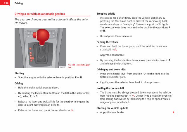
154 Driving
Driving a car with an automatic gearbox
The gearbox changes gear ratios automatically as the vehi-cle moves.
Fig. 115 Automatic gear-box
Starting
– Start the engine with the selector lever in position P or N.
Driving
– Hold the brake pedal pressed down.
– By holding the lock button (button on the left in the selector lev-er), select R, or D.
– Release the lever and wait a little for the gearbox to engage thegear (a slight movement can be felt).
– Release the brake and press the accelerator ⇒ .
Stopping briefly
– If stopping for a short time, keep the vehicle stationary bypressing the foot brake hard to prevent the car moving back-wards on a slope or “creeping” forwards, e.g. at traffic lights.The selector lever does not need to be put into the positions Por N.
– Do not press the accelerator.
Parking the vehicle
– Press and hold the brake pedal until the vehicle comes to astandstill ⇒ .
– Apply the handbrake.
– By pressing the lock button down, move the selector lever to Pand release the lock button.
Driving up and down hills
– Press the selector lever from position “D” to the right into thetiptronic selector gate.
– Lightly press the selector lever back to change down.
Holding the car on a hill
– The brake must be always pressed down to prevent the vehiclefrom “rolling backwards” ⇒ . Do not try to prevent the vehiclefrom rolling backwards by increasing the engine speed while arange of gears is selected.
Starting the vehicle up hills
– Apply the handbrake.

155Driving
– With a selected gear, accelerate slowly and at the same time,release the handbrake.
The steeper the slope, the lower the needed gear. This increases the brak-ing effect of the engine. For example, when driving down a very steep slopein third gear. If the engine brake effect is not enough, the vehicle will speedup. The automatic gearbox automatically changes up to prevent the engineover-revving. Use the foot brake to reduce speed and change into third gearagain using Tiptronic* ⇒ .
Your vehicle has an automatic interlock which prevents the selector leverfrom being put into a position for driving forwards or in reverse from posi-tions P or N if the brake pedal is not depressed.
The ignition key cannot be removed unless the selector lever is in positionP.
Warning lamp “Pressing brake pedal”
When the warning lamp next to the selector lever lights up, press the brakepedal. This is necessary when the automatic gearbox selector lever ismoved out of positions P or N. At the same time, a text message or the in-structions to perform necessary operations may appear on the instrumentpanel.
WARNING
● As a driver, you should never leave your vehicle if the engine is run-ning and a gear is engaged. If you have to leave your vehicle while theengine is running, you must apply the parking brake and put the selectorlever in position P.
● If the engine is running and D or R are engaged, you will need to holdvehicle stopped by depressing the brake pedal. The car would keep oncreeping forward as the power transmission is not fully interrupted evenwhen the engine is idling.
WARNING (Continued)
● Never accelerate when moving the selector gear or you may cause anaccident.
● Never move the selector lever to R or P when driving. Risk of accident!
● Before driving down a long, steep slope, it is advisable to reducespeed and change into a lower gear.
● If you stop the vehicle up hill, always hold the foot brake strongly de-pressed down to stop it from rolling back.
● Never allow the brake to rub and do not use the brake pedal too oftenor for long periods. Constant braking will cause the brakes to overheatand will considerably reduce the brake effect. This increases the brakingdistance and could cause the brake system to fail.
● Never allow the car to roll down a mountain or a slope with the leverin the N or D position, regardless of the engine is running or not.
CAUTION● If you stop the vehicle up hills, do not attempt to stop it from rollingback by depressing the accelerator when a gear has been selected. Other-wise, the automatic gearbox may overheat causing damage. Pull the hand-brake up or fully depress the brake pedal to prevent the vehicle from rollingaway.
● If you allow the car to roll when the engine is not running, or with theselector lever in position N, a lack of lubrication in the automatic gearboxwill damage it.
Safety First Operating Instructions Practical Tips Technical Specifications

156 Driving
Changing gear in tiptronic mode*
The tiptronic system allows the driver to select gears man-ually
Fig. 116 Changing gearwith tiptronic
Fig. 117 Steering wheelwith paddle levers for au-tomatic gearbox
General information about driving in tiptronic mode
Changing gear in tiptronic mode
– Press the selector lever from position D to the right into the tip-tronic selector gate.
– Lightly press the selector forward + to change up into highgears.
– Lightly press the selector lever backwards - to change down intolow gears.
Changing gear with the steering wheel paddle levers*
– Press the right paddle lever + towards the steering wheel tochange up ⇒ fig. 117.
– Press the left paddle lever – towards the steering wheel tochange down ⇒ fig. 117.
Using the paddle levers on the steering wheel, you can access manual driv-ing mode regardless of the pre-selected driving mode.
General information about driving in tiptronic mode
When accelerating, the automatic gearbox / DSG automatic gearbox goesinto a higher gear a little before the engine reaches its maximum permittedrevolutions.
If a lower gear is selected, the automatic gearbox / DSG automatic gearboxwill only change down when the engine cannot go over its maximum permit-ted revolutions.
If tiptronic is selected whilst the vehicle is in motion and the automaticgearbox / DSG automatic gearbox is in third gear and selector lever positionD, tiptronic mode will then also be in third gear.

157Driving
Changing gears in the normal or sport programme using the steering wheelpaddle levers
If the paddle levers ⇒ fig. 117 are used in the normal or sport programme,the system switches temporarily to tiptronic mode. To exit “tiptronic” modeagain, press the right paddle lever + towards the steering wheel for approx-imately one second. You will also leave tiptronic mode if the paddle leversare not moved for a certain time.
Note● The gear paddle levers on the steering wheel can be operated with theselector lever in any position and with the vehicle in motion.
Selector lever positions
The selector lever positions and gears are shown on the in-strument panel screen.
Fig. 118 Automaticgearbox: Instrumentpanel display
Selector lever positions
The selected gear is displayed on the side of the selector lever and on theinstrument panel screen. The currently selected gear for the automatic gear-box will also be shown on the display.
Tiptronic gear indicator
If the automatic gearbox is shifted manually, the selected gears are shownon the screen.
P - parking lock
When the selector lever is in this position, the drive wheels are locked me-chanically.
Position P on the lever must only be selected if the vehicle is stationary.
To move selector lever from position P, the locking button on the selectorlever handle must be pressed and the brake pedal depressed at the sametime while the ignition is switched on.
To put the selector lever in position P, simply press the lock button downand, if necessary, depress the brake pedal down.
R - Reverse gear
The reverse gear is engaged in this position.
Reverse gear must be engaged only when the vehicle is stationary and theengine is idling.
To move the selector lever to position R, press the lock button down and, atthe same time, press the brake pedal down, with the ignition switched on.
With the selector lever in position R and the ignition switched on the follow-ing occurs:
● Reverse lights light up.
● The air conditioner automatically changes the air recirculation mode.
Safety First Operating Instructions Practical Tips Technical Specifications

158 Driving
● The wiper starts if the windscreen washer is on.
● The parking distance warning system switches on.*
N - Neutral (idling)
If this position is selected, the gearbox is in neutral. Power is not transmit-ted to the wheels and the engine does not have a braking function.
Never use the N position to drive down a hill. The engine does not functionas a brake and the brakes are subjected to excessive stain.
You could damage the automatic gearbox if you drive down hills with thegear lever in position N and the engine switched off.
D - Drive (forward)
In this position the gearbox automatically changes to a lower or higher gear,according to the engine's requirements, the driving style and speed. Thebraking effect of the engine when driving downhill is very limited when theselector is in this position. The instrument panel displays the selected gearas well as the selector lever in position D.
If position N has been selected and you wish to select D, you must press thefoot brake if the vehicle is stationary, or travelling at under 5 km/h.
S - Standard driving position (Sport programme)
When the selector lever is in position S, it will automatically change up intoa higher gear later, and change down into a low gear, if compared with posi-tion D. This way, it is possible to take full advantage of the engine reservepower, depending on the engine demand, driving style and speed. Thebraking effect of the engine when driving downhill is very limited. On theinstrument panel display the selected gear is shown as well as the selectorlever to position S.
To select gear range S, press the lock button on the selector lever.
WARNING
If the vehicle moves with no control, an accident and serious injury mayoccur.
● As a driver, you should never leave your vehicle if the engine is run-ning and a gear is engaged. If you have to leave your vehicle while theengine is running, you must always apply the handbrake and engageparking lock P.
● If the engine is running and if D or R are engaged, you will need tohold the vehicle stopped by depressing footbrake down. The car wouldcreep forward as the power transmission is not fully interrupted evenwhen the engine is idling.
● Never accelerate when moving the selector gear or you may cause anaccident.
● Never move the selector lever to “R” or “P” when driving. Risk of acci-dent.
● Before driving down a very steep slope, reduce your speed and shiftto first gear.
● Always hold the vehicle on the foot brake if you stop on hills. Other-wise, the vehicle could roll back.
● Never allow the brake to rub and do not use the brake pedal too oftenor for long periods. Constant braking will cause the brakes to overheatand will considerably reduce the brake effect. This increases the brakingdistance and could cause the brake system to fail.
WARNING
Never switch the engine off until the vehicle is stationary. You could losecontrol of your vehicle. This could cause an accident and serious injury.
● The airbags and belt tensioners do not work when the ignition isswitched off.

159Driving
WARNING (Continued)
● The brake servo does not work with the engine off. You need moreforce to stop the vehicle.
● Power steering does not work when the engine is not running. That iswhy it is much more difficult to turn the steering wheel.
● Never remove the key from the ignition if the vehicle is in motion. Thesteering lock could suddenly engage, and you would not be able to steerthe vehicle.
● Never allow the car to roll downhill with the selector lever in “N”, re-gardless of the engine is running or not.
CAUTIONIf you allow the vehicle to move when the engine is switched off or with theselector lever in position “N”, take your foot off the accelerator and wait un-til the engine starts idling before returning to position “D”.
Kickdown feature
This feature allows maximum acceleration.
If you press the accelerator down thoroughly, the gearbox automaticallychanges down, depending on speed and engine speed, into a lower gear totake full advantage of give the vehicle maximum acceleration.
The gearbox does not change gear until the engine reaches the maximumdetermined engine speed for the gear.
WARNING
You could lose control of the vehicle if you accelerate on slippery roadsurfaces. Risk of serious injury.
● Be particularly careful when using the kickdown features on slipperyroad surfaces. With a fast acceleration, the vehicle could lose tractionand skid.
● You should use the kickdown feature only when traffic and weatherconditions allow it to be used safely.
Handbrake
Using the handbrake
The handbrake should be applied firmly to prevent the vehi-cle from accidentally rolling away.
Fig. 119 Handbrake be-tween the front seats
Safety First Operating Instructions Practical Tips Technical Specifications

160 Driving
Always apply the handbrake when you leave your vehicle and whenyou park.
Applying the handbrake
– Pull the handbrake lever up firmly ⇒ fig. 119.
Releasing the handbrake
– Pull the lever up slightly and press the release knob in the di-rection of the arrow ⇒ fig. 119 and guide the handbrake leverdown fully ⇒ .
Always apply the handbrake as far as it will go in order to prevent you fromdriving with the handbrake applied by mistake ⇒ .
The handbrake warning lamp lights up when the handbrake is appliedand the ignition switched on. The warning turns off when the handbrake isreleased.
WARNING
● Never use the handbrake to stop the vehicle when it is in motion. Thebraking distance is considerably longer, because braking is only appliedto the rear wheels. Risk of accident!
● If it is only partially released, this will cause rear brakes overheating,which can impair the function of the brake system and could lead to anaccident. This also causes premature wear on the rear brake pads.
CAUTIONAlways apply the handbrake before you leave the vehicle. The first gearshould also be selected.
Parking
The handbrake should always be firmly applied when thevehicle is parked.
Always note the following points when parking the vehicle:
– Use the brake pedal to stop the vehicle.
– Apply the handbrake.
– Select first gear.
– Switch the engine off and remove the key from the ignition. Turnthe steering wheel slightly to engage the steering lock.
– Always take you car keys with you when you leave the vehicle⇒ .
Additional notes on parking the vehicle on gradients:
Turn the steering wheel so that the vehicle rolls against the kerb if it startedto roll.
● If the vehicle is parked facing downhill, turn the front wheels so thatthey point towards the kerb.
● If the vehicle is parked facing uphill, turn the front wheels so that theypoint away from the kerb.
● Secure the vehicle as normal by applying the handbrake firmly and se-lecting first gear.

161Driving
WARNING
● Take measures to reduce the risk of injury when you leave your vehi-cle unattended.
● Never park where the hot exhaust system could ignite inflammablematerials, such as dry grass, low bushes, spilt fuel etc.
● Never allow vehicle occupants to remain in the vehicle when it islocked. They would be unable to open the vehicle from the inside, andcould become trapped in the vehicle in an emergency. In the event of anemergency, locked doors will delay assistance to occupants.
● Never leave children alone in the vehicle. They could set the vehiclein motion, for example, by releasing the handbrake or the gear lever.
● Depending on weather conditions, it may become extremely hot orcold inside the vehicle. This can be fatal.
Hill-start assist*
This function is only included in vehicles with ESP.
This device helps when starting uphill.
These are the basic operation conditions: doors closed, brake pedal press-ed down and vehicle in neutral. The system gets activated on engaginggear.
After removing your foot from the brake pedal, the braking force is main-tained for a few seconds to prevent the vehicle from moving backward whenputting into gear. This short space of time is enough to start the vehiclewith ease.
This system also works when reversing uphill.
WARNING
● If you do not start the vehicle immediately after taking your foot offthe brake pedal, the vehicle may start to roll back under certain condi-tions. Depress the brake pedal or use the hand brake immediately.
● If the engine stalls, depress the brake pedal or use the hand brakeimmediately.
● When following a line of traffic uphill, if you want to prevent the vehi-cle from rolling back accidentally when starting off, hold the brake pedaldown for a few seconds before starting off.
NoteThe Official Service or a specialist workshop can tell you if your vehicle isequipped with this system.
Acoustic parking aid system*
Rear parking aid
The parking aid system will use an acoustic signal to warn ofthe approach of any object towards the rear of the vehicle.
Description
The acoustic parking aid system will measure the distance between the rearof the vehicle and any possible obstacle using four ultrasonic sensors loca-ted on the rear bumper. The measuring range of the sensors starts approxi-mately and depending on the nature of the obstacle at a distance of:
● side of the rear bumper: 0.6 m
● middle of the rear bumper: 1.6 m
Safety First Operating Instructions Practical Tips Technical Specifications

162 Driving
Activation
The system is activated by engagement of the reverse gear. A brief acousticsignal confirms the activation and correct function of the system.
Reverse gear
The distance warning will begin as soon as an obstacle is detected by thesystem. The frequency of the bleeps emitted by the system will increase rap-idly as the vehicle approaches the obstacle.
Within a short distance of about 30cm, a continuous signal sounds (stopsignal). The driver should not reverse any further.
Models with a factory-fitted towing bracket: When the vehicle is less than0.35 m away from the obstacle the warning tone will sound continuously.The driver should then not reverse any further.
The warning tone decreases by 30% after 3 seconds from the start of thesystem.
Provided that it is not in continuous mode, the tone on the parking aid sys-tem stops when it detects a wall parallel to the vehicle.
Trailer towing
For vehicles factory-fitted with a towing bar, the parking aid system will notbe activated by the engagement of the reverse gear when pulling a trailer,as the trailer's electric connector will be plugged into the vehicle.
Possible faults
If a continuous beep sounds for some seconds when the reverse gear is en-gaged, this indicates that there is a fault in the parking aid system.
If the fault continues until the ignition is turned off, the acoustic signalwarning of the fault will not be emitted every time the system is reactivated(by engaging the reverse gear). Thus, the system ready indication will notsound either. Have the fault repaired by an Authorised Service Centre assoon as possible.
If there is no ready signal or no acoustic warning signal, then the parkingaid loudspeaker is faulty and may not warn of obstacles.
To ensure that the system works properly, the sensors must be kept cleanand free of ice and snow.
WARNING
● The sensors have blind spots in which obstacles may not be detected.
● Always look out for small children and animals because the systemwill not always detect them. Always pay attention when reversing toavoid accidents.
● The parking aid is not a replacement for driver awareness. The drivermust take full responsibility for parking and other manoeuvres.
CAUTION● Please note that low obstacles detected by the system may no longer beregistered by the sensors as the car moves closer, so the system will notgive any further warning. Certain kinds of obstacles (such as wire fences,chains, thin posts or trailer draw bars, high kerbs or painted railings etc)may not always be detected by the system, so there is a risk of damagingthe vehicle in such cases.
● In some cases, obstacles with uniform edges and bumps may not be de-tected immediately by the system due to their geometry. Take special careof this type of obstacle (corners, rectangular objects, etc.), as they cancause damage to the vehicle.
● Be especially careful when manoeuvring into a corner between two per-pendicular walls. Carefully watch the approach of the wall to the side of thevehicle (using the mirrors).
● The parking aid system does not replace use of the mirrors for manoeu-vres.

163Driving
● External ultra-sonic sources (pneumatic drills, construction machinery,other vehicles with PDC) may interfere with the operation of the system.
● Periodic cleaning of the sensors, take care not to damage or scratchthem. When cleaning with high pressure washers or steam cleaners, thesensors should be sprayed for only a very short period and from a distanceof more than 10 cm.
Cruise speed* (Cruise control system)
Description
The cruise control system is able to maintain the set speedin the range of 30 km/h to 180 km/h.
Once the speed setting has been saved, you may take your foot off the ac-celerator.
WARNING
It could be dangerous to use the cruise control system if it is not possibleto drive at constant speed.
● Do not use the cruise control system when driving in dense traffic, onroads with lots of bends or on roads with poor conditions (with ice, slip-pery surfaces, loose grit or gravel), as this could cause an accident.
● Always switch the cruise control system off after using it in order toavoid an involuntary use.
● It is dangerous to use a set speed which is too high for the currentroad, traffic or weather conditions. Risk of accident.
NoteThe cruise control cannot maintain a constant speed when descendingdownhill. The vehicle will accelerate due to its own weight. Use the footbrake to slow the vehicle.
Switching the cruise control system on and off
Fig. 120 Turn signal andmain beam headlight lev-er: switch and rockerswitch for the cruise con-trol
Switching on the system
– Move the control ⇒ fig. 120 A to the left to ON.
Switching off the system
– Move the control A to the right to OFF or turn the ignition offwhen the vehicle is stationary.
Safety First Operating Instructions Practical Tips Technical Specifications

164 Driving
When the cruise control is on and a speed is programmed, the indicator on the instrument panel is lit.1)
If the cruise control system is switched off, the symbol is switched off.The system will also be deactivated completely when 1st gear is selected.*
Setting speed*
Fig. 121 Turn signal andmain beam headlight lev-er: switch and rockerswitch for the cruise con-trol
– Press the lower part SET of the rocker switch ⇒ fig. 121 B oncebriefly when you have reached the speed you wish to set.
When you release the rocker switch, the current speed is set and held con-stant.
Adjusting set speed*
The speed can be altered without touching the accelerator orthe brake.
Fig. 122 Turn signal andmain beam headlight lev-er: switch and rockerswitch for the cruise con-trol
Setting a higher speed
– Press the upper part RES of the rocker switch ⇒ fig. 122 B toincrease the speed. The vehicle will continue to accelerate aslong as you keep the rocker switch pressed. When you releasethe switch, the new speed is stored.
Setting a lower speed
– Press the lower part SET– of the rocker switch B to reduce thespeed. The vehicle will automatically reduce its speed for aslong as you keep the switch pressed. When you release theswitch, the new speed is stored.
1) Depending on the model version

165Driving
When you increase speed with the accelerator and then release the pedal,the system will automatically restore the set speed. This will not be thecase, however, if the vehicle speed is more than 10 km/h higher than thestored speed for longer than 5 minutes. The speed will have to be storedagain.
Cruise control is switched off if you reduce speed by depressing the brakepedal. Reactivate the control by pressing once on the upper part of the rock-er switch RES+ ⇒ fig. 122 B .
WARNING
It is dangerous to use a set speed which is too high for the current road,traffic or weather conditions. Risk of accident.
Switching off the system temporarily*
Fig. 123 Turn signal andmain beam headlight lev-er: switch and rockerswitch for the cruise con-trol
The cruise control system will be switched off in the following situations:
● if the brake pedal is depressed,
● if the clutch pedal is depressed,
● if the vehicle is accelerated to over 180 km/h,
● when the lever A is moved in the direction of OFF without fully beingengaged.
To resume cruise control, release the brake or clutch pedal or reduce the ve-hicle speed to less than 180 km/h and press once on the upper part of therocker switch RES ⇒ fig. 123 B .
WARNING
It is dangerous to use a set speed which is too high for the current road,traffic or weather conditions. Risk of accident.
Completely switching off the system
Fig. 124 Turn signal andmain beam headlight lev-er: switch and rockerswitch for the cruise con-trol
Safety First Operating Instructions Practical Tips Technical Specifications

166 Driving
Vehicles with a manual gearbox
The system is completely turned off by moving the control A all the way tothe right hand side (OFF engaged), or when the vehicle is stationary, igni-tion off.
Vehicles with an automatic gearbox
To completely disengage the system, the selector lever must be placed inone of the following positions: P, N, R or 1 or with the vehicle stopped andthe ignition turned off.

167Intelligent technology
Practical Tips
Intelligent technology
Brakes
Brake servo
The brake servo increases the pressure you apply to the brake pedal. Itworks only when the engine is running.
If the brake servo is not functioning due to a malfunction, or if the vehiclehas to be towed, you will have to press the brake pedal considerably harderto make up for the lack of servo assistance.
WARNING
The braking distance can also be affected by external factors.
● Never let the vehicle coast with the engine switched off. Failure to doso could result in an accident. The braking distance is increased consid-erably when the brake servo is not active.
● If the brake servo is not working, for example when the vehicle is be-ing towed, you will have to press the brake pedal considerably harderthan normal.
Hydraulic Brake Assist (HBA)*
The Hydraulic Brake Assist function (HBA) is only included invehicles with ESP.
In an emergency, most drivers brake in time, but not with maximum force.This results in unnecessarily long braking distances.
This is when the brake assist system comes into action. When pressing thebrake pedal rapidly, the assistant interprets it as an emergency. It then veryquickly builds up the full brake pressure so that the ABS can be activatedmore quickly and efficiently, thus reducing the braking distance.
Do not reduce the pressure on the brake pedal. The brake assist systemswitches off automatically as soon as you release the brake.
Automatic hazard warning lights activation
The brake lights flash automatically to indicate that the vehicle is brakingsuddenly or in an emergency situation. If the emergency braking continuesuntil the vehicle comes to a standstill, the hazard warning lights will thencome on and the brake lights will remain on permanently from that moment.The warning lights will automatically switch off when the vehicle begins tomove again or when the "warning" light button is pressed.
Safety First Operating Instructions Practical Tips Technical Specifications

168 Intelligent technology
WARNING
● The risk of accident is higher if you drive too fast, if you do not keepyour distance to the vehicle in front, and when the road surface is slip-pery or wet. The increased accident risk cannot be reduced by the brakeassist system.
● The brake assist system cannot defy the laws of physics. Slipperyand wet roads are dangerous even with the brake assist system! There-fore, it is essential that you adjust your speed to suit the road and trafficconditions. Do not let the extra safety features tempt you into taking anyrisks when driving.
Anti-lock brake system and traction controlABS
Anti-lock brake system (ABS)
The anti-lock brake system prevents the wheels locking dur-ing braking.
The anti-lock brake system (ABS) is an important part of the vehicle's activesafety system.
How the ABS works
If one of the wheels is turns too slowly in relation to the road speed, and isclose to locking, the system will reduce the braking pressure for this wheel.The driver is made aware of this control process by a pulsating of the brakepedal and audible noise. This is a deliberate warning to the driver that oneor more of the wheels is tending to lock and the ABS control function hasintervened. In this situation it is important to keep the brake pedal fully de-pressed so the ABS can regulate the brake application. Do not “pump”.
If you brake hard on a slippery road surface, the best possible control is re-tained as the wheels do not lock.
However, ABS will not necessarily guarantee shorter braking distances in allconditions. The braking distance could even be longer if you brake on gravelor on fresh snow covering a slippery surface.
WARNING
● The anti-lock brake system cannot defy the laws of physics. Slipperyand wet roads are dangerous even with ABS! If you notice that the ABS isworking (to counteract locked wheels under braking), you should reducespeed immediately to suit the road and traffic conditions. Do not let theextra safety features tempt you into taking any risks when driving.
● The effectiveness of ABS is also determined by the tyres fitted⇒ page 215.
● If the running gear or brakes are modified, the effectiveness of theABS could be severely limited.
Traction control system (TCS)*
The traction control system prevents the drive wheels fromspinning when the vehicle is accelerating. The system al-ways includes ABS
Description and operation of the traction control system duringacceleration (TCS)
TCS reduces engine power to help prevent the drive wheels of front-wheeldrive vehicles losing traction during acceleration. The system works in theentire speed range in conjunction with ABS. If a malfunction occurs in theABS, the TCS will also be inoperative.

169Intelligent technology
TCS helps the vehicle to start moving, accelerate and climb a gradient inslippery conditions where this may otherwise be difficult or even impossi-ble.
The TCS is switched on automatically when the engine is started. If necessa-ry, it may be turned on or off by briefly pushing the ESP button on the centreconsole.
When the TCS is off, the warning lamp is lit. The TCS should normally beleft on. Only in exceptional circumstances, when the slipping of the wheelsis required, can they be disconnected using the ESP button, for example.
● With compact temporary spare wheel.
● When using the snow chains.
● When driving in deep snow or on loose surfaces
● When the vehicle is bogged-down, to free it by rocking.
The TCS should be switched on again as soon as possible.
WARNING
● It must be remembered that TCS cannot defy the laws of physics. Thisshould be kept in mind, particularly on slippery and wet roads and whentowing a trailer.
● Always adapt your driving style to suit the condition of the roads andthe traffic situation. Do not let the extra safety afforded by TCS tempt youinto taking any risks when driving, this can cause accidents.
CAUTION● In order to ensure that TCS function correctly, all four wheels must be fit-ted with the same tyres. Any differences in the rolling radius of the tyres cancause the system to reduce engine power when this is not desired.
● Modifications to the vehicle (e.g. to the engine, the brake system, run-ning gear or any components affecting the wheels and tyres) could affectthe efficiency of the ABS and TCS.
XDS*
Driveshaft differential
When taking a bend, the driveshaft differential mechanism allows the outerwheel to turn at a higher speed than the inner wheel. In this way, the wheelthat is turning faster (outer wheel) receives less drive torque than the innerwheel. This may mean that in certain situations the torque delivered to theinner wheel is too high, causing the wheels to spin. On the other hand, theouter wheel is receiving a lower drive torque than it could transmit. Thiscauses an overall loss of lateral grip on the front axle, resulting in under-steer or “lengthening” of the trajectory.
By using the ESP sensors and signals, the XDS system is able to detect andcorrect this effect.
Through the ESP, the XDS brakes the inner wheel, thereby counteracting theexcess drive torque in this wheel. This means that the driver's desired tra-jectory is much more precise,
The XDS system operates in combination with the ESP and is always active,even when the traction control, TCS, is disconnected.
Electronic Stability Programme (ESP)*
General notes
The Electronic Stability Programme increases the vehicle'sstability on the road.
The Electronic Stability Programme helps reduce the danger of skidding.
The Electronic Stability Programme (ESP) consists of ABS, EDL and TCS.
Safety First Operating Instructions Practical Tips Technical Specifications

170 Intelligent technology
Electronic Stability Programme (ESP)*
ESP reduces the danger of skidding by braking the wheels individually.
The system uses the steering wheel angle and road speed to calculate thechanges of direction desired by the driver, and constantly compares themwith the actual behaviour of the vehicle. If the desired course is not beingmaintained (for instance, if the vehicle is starting to skid), then the ESPcompensates automatically by braking the appropriate wheel.
The forces acting on the braked wheel bring the vehicle back to a stablecondition. If the vehicle tends to oversteer, the system will act on the frontwheel on the outside of the turn.
WARNING
● It must be remembered that ESP cannot defy the laws of physics. Thisshould be kept in mind, particularly on slippery and wet roads and whentowing a trailer.
● Always adapt your driving style to suit the condition of the roads andthe traffic situation. Do not let the extra safety afforded by ESP tempt youinto taking any risks when driving, as this can cause accidents.
CAUTION● In order to ensure that ESP functions correctly, all four wheels must befitted with the same tyres. Any differences in the rolling radius of the tyrescan cause the system to reduce engine power when this is not desired.
● Modifications to the vehicle (e.g. to the engine, the brake system, run-ning gear or any components affecting the wheels and tyres) could affectthe efficiency of the ABS, EDL, ESP and TCS.
Anti-lock brake system (ABS)
The anti-lock brake system prevents the wheels locking during braking⇒ page 168.
Electronic differential lock (EDL)*
The electronic differential lock helps prevent the loss of trac-tion caused if one of the driven wheels starts spinning.
EDL helps the vehicle to start moving, accelerate and climb a gradient inslippery conditions where this may otherwise be difficult or even impossi-ble.
The system will control the revolutions of the drive wheels using the ABSsensors (in case of an EDL fault the warning lamp for ABS lights up)⇒ page 69.
At speeds of up to approximately 80 km/h, it is able to balance out differen-ces in the speed of the driven wheels of approximately 100 rpm caused by aslippery road surface on one side of the vehicle. It does this by braking thewheel which has lost traction and distributing more driving force to the oth-er driven wheel via the differential.
To prevent the disc brake of the braking wheel from overheating, the EDLcuts out automatically if subjected to excessive loads. The vehicle will con-tinue to function normally without EDL. For this reason, the driver is not in-formed that the EDL has been switched off.
The EDL will switch on again automatically when the brake has cooleddown.
171Intelligent technology
WARNING
● When accelerating on a slippery surface, for example on ice andsnow, press the accelerator carefully. Despite EDL, the driven wheels maystart to spin. This could impair the vehicle's stability.
● Always adapt your driving style to suit road conditions and the trafficsituation. Do not let the extra safety afforded by EDL tempt you into tak-ing any risks when driving, this can cause accidents.
CAUTIONModifications to the vehicle (e.g. to the engine, the brake system, runninggear or any components affecting the wheels and tyres) could affect the effi-ciency of the EDL ⇒ page 189.
The traction control system (TCS)
The traction control system prevents the drive wheels from spinning whenthe vehicle is accelerating ⇒ page 168.
Safety First Operating Instructions Practical Tips Technical Specifications

172 Driving and the environment
Driving and the environment
Running-in
Running in a new engine
The engine needs to be run in over the first 1500 km.
Up to 1000 kilometres
– Do not drive at speeds of more than 2/3 the maximum speed.
– Do not accelerate hard.
– Avoid high engine revolutions.
– Do not tow a trailer.
From 1000 to 1500 kilometres
– Speeds can be gradually increased to the maximum road speedor maximum permissible engine speed (rpm).
During its first few hours of running, the internal friction in the engine isgreater than later on, when all the moving parts have bedded in.
For the sake of the environmentIf the engine is run in gently, its life will be increased and its oil consump-tion reduced.
Running in tyres and brake pads
New tyres should be run-in carefully for the first 500 km.New brake pads should be run-in carefully for the first 200km.
During the first 200 km, you can compensate for the reduced braking effectby applying more pressure to the brake pedal. In case of a sharp braking,the braking distance will be longer with new brake pads than with brakepads which have been run-in.
WARNING
● At first, new tyres do not give maximum grip, and require running-in.This may cause an accident. Drive particularly carefully in the first 500km.
● New brake pads must be “run in” and do not have the correct frictionproperties during the first 200 km. However, the reduced braking capaci-ty may be compensated by pressing on the brake pedal a little harder.
Braking capacity and braking distance
The braking capacity and braking distance are influenced bydriving situations and road conditions.
The efficiency of the brakes depends directly on the brake pad wear. Therate of wear of the brake pads depends to a great extent on the conditionsunder which the vehicle is operated and the way the vehicle is driven. If youoften drive in town traffic, drive short distances or have a sporty drivingstyle, we recommend that you have the thickness of your brake pads

173Driving and the environment
checked by an Authorised Service Centre more frequently than recommen-ded in the Service Plan.
If you drive with wet brakes, for example, after crossing areas of water, inheavy rainfall or even after washing the vehicle, the effect of the brakes islessened as the brake discs are wet or even frozen (in winter). In this casethe brakes should be dried by pressing the brake pedal several times.
WARNING
Longer braking distances and faults in the brake system increase the riskof accidents.
● New brake pads must be run in and do not have the correct frictionduring the first 200 km. However, the reduced braking capacity may becompensated by pressing on the brake pedal a little harder. This also ap-plies when the brake pads have to be changed further on.
● If brakes are wet or frozen, or if you are driving on roads which havebeen salted, braking power may be lower than normal.
● On steep slopes, if brakes are excessively used, they will overheat.Before driving down a long steep slope, it is advisable to reduce speedand change down into a lower gear or range (depending on the type oftransmission). This makes use of engine braking and relieves the brakes.
● Never let the brakes “drag” by applying light pressure. Continuousbraking will cause the brakes to overheat and the braking distance willincrease. Apply and then release the brakes alternately.
● Never let the vehicle run with the engine switched off. The brakingdistance is increased considerably when the brake servo is not active.
● If the brake fluid loses its viscosity and is subjected to heavy use, va-pour bubbles can form in the brake system. This reduces the efficiency ofthe brakes.
WARNING (Continued)
● Non-standard or damaged front spoilers could restrict the airflow tothe brakes and cause them to overheat. Before purchasing accessoriesplease observe the relevant instructions ⇒ page 189, Technical modifi-cations.
● If a brake circuit fails, the braking distance will be increased consider-ably. Contact a specialised workshop immediately and avoid unnecessa-ry journeys.
Exhaust gas purification system
Catalytic converter*
To maintain the useful life of the catalytic converter
– Use only unleaded petrol with petrol engines, as lead damagesthe catalytic converter.
– Do not let the fuel get too low in the tank.
– For engine oil changes, do not replenish with too much engineoil ⇒ page 204, Topping up engine oil .
– Never tow the vehicle to start it, use jump leads if necessary⇒ page 246.
If you notice misfiring, uneven running or loss of power when the vehicle ismoving, reduce speed immediately and have the vehicle inspected at thenearest specialised workshop. In general, the exhaust gas warning lampwill light up when any of the described symptoms occur ⇒ page 63. If thishappens, unburnt fuel can enter the exhaust system and escape into the en-vironment. The catalytic converter can also be damaged by overheating.
Safety First Operating Instructions Practical Tips Technical Specifications

174 Driving and the environment
WARNING
The catalytic converter reaches very high temperatures! There is a risk offire.
● Never park where the catalytic converter could come into contact withdry grass or flammable materials under the vehicle.
● Do not apply additional underseal or anti-corrosion coatings to theexhaust pipes, catalytic converter or the heat shields on the exhaust sys-tem. These materials could catch fire when the vehicle is being driven.
CAUTIONNever run the fuel tank completely dry because the irregularity of the fuelsupply may cause ignition problems. This allows unburnt fuel to enter theexhaust system, which could cause overheating and damage the catalyticconverter.
For the sake of the environmentEven when the emission control system is working perfectly, there may be asmell of sulphur from the exhaust gas under some conditions. This dependson the sulphur content of the fuel used. Quite often the problem can besolved by changing to another brand of fuel.
Diesel engine particulate filter*
The diesel engine particulate filter eliminates soot producedby burning diesel.
Fig. 125 Vehicle datasticker on back cover ofthe Maintenance Pro-gramme
Your vehicle is fitted with a DPF (Diesel particulate filter) if the vehicle datasticker (back cover of the “Maintenance Programme”) lists the PR code 7GGor 7MG ⇒ fig. 125.
The diesel engine particulate filter eliminates most of the soot from the ex-haust gas system. Under normal driving conditions, the filter cleans itself. Ifthe driving conditions do not allow the filter to clean itself (for example,multiple short trips) the filter will be obstructed by dust and pollen and theindicator for the diesel engine particulate filter indicator will light up.This does not represent a fault, it is a warning that indicates that the filterhas not been able to regenerate automatically and that you must carry out acleaning cycle, as indicated in ⇒ page 68.
175Driving and the environment
WARNING
● The diesel engine particulate filter may reach extremely high temper-atures; the vehicle should be parked so that the exhaust pipe does notcome into contact with flammable materials underneath the vehicle. Oth-erwise there is a risk of fire.
CAUTION● Your vehicle is not designed to use biodiesel fuel. Never, under any cir-cumstances refuel with biodiesel. The use of biodiesel fuel could damagethe engine and the fuel system. The addition of biodiesel to diesel by thediesel producer in accordance with standard EN 590 is authorised and willnot cause damage to the engine or the fuel system.
● Using diesel fuel with a high sulphur content may significantly reducethe working life of the diesel particulate filter. Your Authorised Service Cen-tre will be able to tell you which countries have diesel with a high sulphurcontent.
Economical and environmentally friendlydriving
Economical and environmentally friendly driving
Fuel consumption, environmental pollution and wear to the engine, brakesand tyres depends in large part on your driving style. By adopting an eco-nomical driving style and anticipating the traffic situation ahead, you caneasily reduce fuel consumption by 10-15%. Some tips on how to help youreduce pollution while saving money are listed below.
Drive anticipating the traffic situation
A vehicle uses most fuel when accelerating. When you anticipate the situa-tion, you have to brake less often and, thus, accelerate less. If it is possible,let the vehicle roll with a gear engaged, for example, if you see a red lightahead. The braking effect achieved in this way helps to reduce the wear ofbrakes and tyres; emissions and fuel consumption are reduced to zero (dis-connection due to inertia).
Change gear early to save energy
An effective way of saving fuel is to change up quickly through the gears.Running the engine at high rpm in the lower gears uses an unnecessaryamount of fuel.
Manual gearbox: Change from first to second gear as quickly as possible.We recommend that, whenever possible, you change to a higher gear uponreaching 2000 rpm. Follow the “recommended gear” indication that ap-pears on the instrument panel ⇒ page 58.
Avoid driving at high speed
We advise you not to drive at the top speed permitted by the vehicle. Fuelconsumption, exhaust emissions and noise levels all increase very rapidlyat higher speeds. Driving at moderate speeds will help to save fuel.
Avoid idling
It is worthwhile switching off the engine when waiting in a traffic jam, at lev-el crossings or at traffic lights with a long red phase. The fuel saved afteronly 30 - 40 seconds is greater than the amount of fuel needed to restartthe engine.
The engine takes a long time to warm up when it is idling. Mechanical wearand pollutant emissions are also especially high during this initial warm-upphase. It is therefore best to drive off immediately after starting the engine.Avoid running the engine at high speed.
Periodic maintenance
Periodic maintenance work guarantees that, before beginning a journey,you will not consume more than the required amount of fuel. A well-serviced
Safety First Operating Instructions Practical Tips Technical Specifications

176 Driving and the environment
engine gives you the benefit of improved fuel efficiency as well as maxi-mum reliability and an enhanced resale value.
A badly serviced engine can consume up to 10% more fuel than necessary.
Avoid short journeys
To reduce the consumption and emission of polluting gases, the engine andthe exhaust filtration systems should reach the optimum service tempera-ture.
With the engine cold, fuel consumption is proportionally higher. The enginedoes not warm up and fuel consumption does not normalise until havingdriven approximately four kilometres. This is why we recommend avoidingshort trips whenever possible.
Maintain the correct tyre pressures
Bear in mind that keeping the tyres at an adequate pressure saves fuel. Ifthe tyre pressure is just one bar too low, fuel consumption can increase byas much as 5%. Due to the greater rolling resistance, under-inflation alsoincreases tyre wear and impairs handling.
The tyre pressures should always be checked when the tyres are cold.
Do not use winter tyres all year round as they increase fuel consumption byup to 10%.
Avoid unnecessary weight
Every kilo of extra weight will put up the fuel consumption, so it is worthchecking the luggage compartment occasionally to make sure that no un-necessary loads are being transported.
A roof rack is often left in place for the sake of convenience, even when it isno longer needed. At a speed of 100-120 km/h your vehicle will use about12% more fuel as a result of the extra wind resistance caused by the roofrack even when it is not in use.
Save electricity
The engine activates the alternator, which produces electricity. With theneed for electricity, fuel consumption is also increased. Because of this, al-ways turn off electrical components when you do not need them. Examplesof components that use a lot of electricity are: the fan at high speeds, therear window heating or the seat heaters*.
Note● If you vehicle has Start-Stop, it is not recommended to disconnect thisfunction.
● It is recommended to close the windows when driving at more than 60km/h
● Do not drive with your foot resting on the clutch pedal, as the pressurecan make the plate spin, more fuel will be used and it can burn the clutchplate lining, causing a serious fault.
● Do not hold the vehicle on a hill with the clutch, use the foot brake orhand brake, using the latter to start. The fuel consumption will be lower andyou will prevent the clutch plate from being damaged.
● On descents, use the engine brake, changing to the gear that is moresuitable for the slope. The fuel consumption will be lower and the brakeswill not suffer.
Environmental friendliness
Environmental protection is a top priority in the design, choice of materialsand production of your new Seat.
Design measures for economical recycling
● Joints and connections designed for easy dismantling
● Modular construction to facilitate dismantling

177Driving and the environment
● Increased use of single-grade materials
● Plastic parts and elastomers are marked in accordance with ISO 1043,ISO 11469 and ISO 1629
Choice of materials
● Nearly all materials used can be recycled
● Similar types of plastics grouped together for easy recycling
● Recycled materials used in manufacture
● Reduction of volatile compounds in plastics
● CFC-free refrigerant in air conditioner
Compliance with prohibited materials regulation: cadmium, lead, mercury,chrome VI.
Manufacturing methods
● Use of recycled material for manufacturing plastic parts
● Solvent-free cavity sealing
● Solvent-free wax for protecting the vehicles in transit
● Solvent-free adhesives
● No CFCs used in production
● Surplus materials used extensively for energy conversion and buildingmaterials
● Overall water consumption reduced
● Heat recovery systems
● The use of water-soluble paints
Driving abroad
Observations
To drive abroad, the following must be taken into consideration:
● For vehicles fitted with a catalytic converter ensure that unleaded petrolis available for the journey. See the chapter “Refuelling”. Automobile organ-isations will have information about service station networks selling unlea-ded fuel.
● In some countries, it is possible that your vehicle model is not sold, andtherefore spare parts are not available or the Authorised Services can onlycarry out limited repairs.
SEAT importers and distributors will gladly provide information about thetechnical preparations that you vehicle requires and also about necessarymaintenance and repair possibilities.
Adhesive strips for headlights
If you have to drive a right-hand drive vehicle in a left-hand drive country, orvice versa, the asymmetric dipped beam headlights will dazzle oncomingtraffic.
To prevent dazzling, you must apply stickers to certain parts of the head-light lenses. Further information is available at your Authorised Service Cen-tre.
In vehicles with adaptive headlights, the rotation system must previously bedisconnected. To do this, please go to a specialised workshop.
Safety First Operating Instructions Practical Tips Technical Specifications

178 Driving and the environment
Trailer towing
What do you need to bear in mind when towing a trailer?
Your vehicle may be used to tow a trailer when fitted with the correct equip-ment.
If the car is supplied with a factory-fitted towing bracket it will already havethe necessary technical modifications and meet the statutory requirementsfor towing a trailer. If you wish to retrofit a towing bracket, consult⇒ page 191.
Connectors
Your vehicle is fitted with a 12-pin connector for the electrical connectionbetween the trailer and the vehicle.
If the trailer has a 7-pin plug you will need to use an adapter cable. This isavailable in any SEAT dealer.
Trailer weight / drawbar load
Never exceed the authorised trailer weight. If you do not load the trailer upto the maximum permitted trailer weight, you can then climb correspond-ingly steeper slopes.
The maximum trailer weights listed are only applicable for altitudes up to1000 m above sea level. With increasing altitude the engine power andtherefore the vehicle's climbing ability are impaired because of the reducedair density. The maximum trailer weight has to be reduced accordingly. Theweight of the vehicle and trailer combination must be reduced by 10% forevery further 1000 m (or part thereof). The gross combination weight is theactual weight of the laden vehicle plus the actual weight of the laden trailer.When possible, operate the trailer with the maximum permitted drawbarload on the ball joint of the towing bracket, but do not exceed the specifiedlimit.
The figures for trailer weights and drawbar loads that are given on the dataplate of the towing bracket are for certification purposes only. The correctfigures for your specific model, which may be lower than these figures forthe towing bracket, are given in the vehicle documents or in ⇒ chapter Tech-nical Data.
Distributing the load
Distribute loads in the trailer so that heavy objects are as near to the axle aspossible. Loads carried in the trailer must be secured to prevent them mov-ing.
Tyre pressure
Set tyre pressure to the maximum permissible pressure shown on the stick-er on the inside of the fuel tank flap. Set the tyre pressure of the trailer tyresin accordance with the trailer manufacturer's recommendations.
Exterior mirrors
Check whether you can see enough of the road behind the trailer with thestandard mirrors. If this is not the case, you should have additional mirrorsfitted. Both exterior mirrors should be mounted on hinged extension brack-ets. Adjust the mirrors to give sufficient vision to the rear.
WARNING
Never transport people in a trailer. This could result in fatal accidents.
Note● Towing a trailer places additional demands on the vehicle. We recom-mend additional services between the normal inspection intervals if the ve-hicle is used frequently for towing a trailer.
● Find out whether special regulations apply to towing a trailer in yourcountry.

179Driving and the environment
Ball coupling of towing bracket*
The ball coupling is provided with instructions on fitting and removing theball coupling of the towing bracket.
WARNING
The towing bracket ball coupling must be stored securely in the luggagecompartment to prevent them being flung through the vehicle and caus-ing injury.
Note● By law, the ball coupling must be removed if a trailer is not being towedand it obscures the number plate.
Driving tips
Driving with a trailer always requires extra care.
Weight distribution
The weight distribution of a loaded trailer with an unladen vehicle is veryunfavourable. However, if this cannot be avoided, drive extra slowly to allowfor the unbalanced weight distribution.
Speed
The stability of the vehicle and trailer is reduced with increasing speed. Forthis reason, it is advisable not to drive at the maximum permissible speedin an unfavourable road, weather or wind conditions. This applies especiallywhen driving downhill.
You should always reduce speed immediately if the trailer shows the slight-est sign of snaking. Never try to stop the “snaking” by increasing speed.
Always brake in due course. If the trailer has an overrun brake, apply thebrakes gently at first and then, firmly. This will prevent the jerking that canbe caused by the trailer wheels locking. Select a low gear in due course be-fore going down a steep downhill. This enables you to use the engine brak-ing to slow down the vehicle.
Reheating
At very high temperatures and during prolonged slopes, driving in a lowgear and high engine speed, always monitor the coolant temperature gauge⇒ page 53.
Electronic Stability Programme*
The ESP* system helps to stabilise the trailer in case of skidding or rocking.
Safety First Operating Instructions Practical Tips Technical Specifications

180 Vehicle maintenance and cleaning
Vehicle maintenance and cleaning
General notes
Regular washing and care help maintain the value of yourvehicle.
Vehicle maintenance
Regular care and washing help to maintain the value of the vehicle. Thismay also be one of the requirements for acknowledging warranty claims inthe event of bodywork corrosion or paint defects.
The best way to protect your vehicle against the harmful effects of the envi-ronment is through correct maintenance and frequent washing. The longersubstances such as insect remains, bird droppings, resinous tree sap, roaddirt, industrial deposits, tar, soot or road salt and other aggressive materi-als remain on the vehicle, the more damage they do to the paintwork. Hightemperatures (for instance in strong sunlight) further intensify the corrosiveeffect.
After winter, a period when salt is put on the roads, it is important to havethe underside of the vehicle washed thoroughly.
Products for vehicle maintenance
Car care products are available in your Authorised Service Centre. Keep theproduct instructions until you have used them up.
WARNING
● Car care products can be toxic. Because of this, they must always bekept closed in their original container. Keep them out of the reach of chil-dren. Failure to comply could result in poisoning.
● Always read and observe the instructions and warnings on the pack-age before using vehicle care products. Improper use could cause healthproblems or damage the vehicle. The use of certain products may pro-duce noxious vapours; they should be used in well ventilated areas.
● Never use fuel, turpentine, engine oil, nail varnish remover or othervolatile fluids. These are toxic and highly flammable. Risk of fire and ex-plosion.
● Before washing your vehicle, or carrying out any maintenance, switchthe engine off, apply the handbrake firmly and remove the key from theignition.
CAUTIONNever attempt to remove dirt, mud or dust if the surface of the vehicle is dry.Never use a dry cloth or sponge for cleaning purposes. This could damagethe paintwork or the windows of your vehicle. Soak dirt, mud or dust withplenty of water.
For the sake of the environment● When purchasing products for your vehicle maintenance, select theones which are not harmful to the environment.
● The waste from car care products should not be disposed of with ordina-ry household waste. Observe the disposal information on the package.

181Vehicle maintenance and cleaning
Care of the vehicle exterior
Automatic car washing tunnel
The vehicle paintwork is so durable that the vehicle can normally be washedwithout problems in an automatic car wash tunnel. However, the paintworkwear depends to a large extent on the kind of the car wash tunnel, thebrushes used, its water filtering and the type of cleaning and preservativeproducts.
Before going through a car wash, be sure to take the usual precautions suchas closing the windows and sunroof. There is nothing to note apart fromthat.
If the vehicle has special accessories such as spoilers or a roof rack or two-way radio aerial, etc., it is advisable to consult the car wash tunnel operator.
After washing, the brakes could take some time to respond as the brakediscs and pads could be wet, or even frozen in winter. Dry the brakes bybraking several times.
WARNING
Water, ice and salt on the brakes can reduce braking efficiency. Risk ofaccident.
CAUTIONBefore putting the vehicle through the car washing tunnel, do not tightenthe aerial if it is folded because it can be damaged.
Washing by hand
Vehicle washing
– First soften the dirt and rinse it off with water.
– Clean your vehicle from top to bottom with a soft sponge, aglove or a brush. Use very light pressure.
– Rinse the sponge or glove often with clean water.
– Special car shampoo should only be used for very stubborn dirt.
– Leave the wheels, sill panels etc. until last, using a differentsponge or glove.
– Rinse the vehicle thoroughly with water.
– Dry the vehicle surface gently with a chamois leather.
– In cold temperature, dry the rubber seals and their surfaces toprevent them from freezing. Apply silicone spray to the rubberseals.
After washing the vehicle
– After washing, avoid sudden and sharp braking. Dry the brakesby braking several times.
Safety First Operating Instructions Practical Tips Technical Specifications

182 Vehicle maintenance and cleaning
WARNING
● Wash your vehicle with the ignition switched off.
● Protect your hands and arms from cuts on sharp metal edges whencleaning the underbody, the inside of the wheel housings etc. Risk of in-jury.
● Water, ice and salt on the brakes can reduce braking efficiency. Riskof accident.
CAUTION● Never remove dirt, mud or dust if the vehicle surface is dry. Never use adry cloth or sponge for cleaning purposes. This could scratch the paintworkor glass on your vehicle.
● Washing the vehicle in low temperatures: when washing the vehiclewith a hose, do not direct water into the lock cylinders or the gaps aroundthe doors, tailgate, or sunroof. Risk of freezing.
For the sake of the environmentTo protect environment, the vehicle should be washed only in specially pro-vided wash bays. This prevents toxic, oil-laden waste water entering thesewerage system. In some places, washing vehicles outside wash bays isprohibited.
NoteDo not wash the vehicle in direct sunlight.
Washing the vehicle with a high pressure cleaner
Be particularly careful when using a high pressure cleaner!
– Always observe the instructions for the high-pressure cleaner,particularly those concerning the pressure and the sprayingdistance.
– Increase the spraying distance for soft materials and paintedbumpers.
– Do not use a high pressure cleaner to remove ice or snow fromwindows ⇒ page 183.
– Never use concentrated jet nozzles (“rotating jets”) ⇒ .
– After washing, avoid sudden and sharp braking. “Dry” thebrakes by braking several times ⇒ page 172.
WARNING
● Never wash tyres with a concentrated jet (“rotating nozzle”). Even atlarge spraying distances and short cleaning times, visible and invisibledamage can occur to the tyres. This may cause an accident.
● Water, ice and salt on the brakes can reduce braking efficiency. Riskof accident.
CAUTION● Do not use water hotter than 60 °C. This could damage the car.
● To avoid damage to the vehicle, keep a sufficient distance from sensitivematerials such as flexible hoses, plastic, soundproofing material, etc. Thisis also important for bumpers painted in the colour of the bodywork. Thecloser the nozzle is to the surface, the greater the wear on the material.

183Vehicle maintenance and cleaning
Vehicle paint maintenance
Regular waxing protects the paintwork.
You need to apply wax to your vehicle if water does not form small dropsand run off the paintwork when it is clean.
Good quality hard wax products are available at your Authorised ServiceCentre.
Regular wax applications help to protect the paintwork from environmentalcontaminants ⇒ page 180. It is also effective in protecting against minorscratches.
Even if a wax solution is used regularly in the vehicle washing tunnel, it isadvisable to protect the paint with a hard wax coating at least twice a year.
Polishing the paintwork
Polishing brings back gloss to the paintwork.
Polishing is only necessary if the paint has lost its shine, and the gloss can-not be brought back by applying wax. Polishing products can be purchasedin your Authorised Service Centre.
The vehicle must be waxed after polishing if the polish used does not con-tain wax compounds to seal the paint ⇒ page 183, Vehicle paint mainte-nance.
CAUTIONTo prevent damage to the paintwork:
● Do not use polishes and hard wax on painted parts with a matte finishor on plastic parts.
● Do not polish your vehicle in a sandy or dusty environment.
Caring for plastic parts
Solvents damage plastic parts.
If normal washing fails to clean plastic parts, clean them with approved sol-vent-free plastic cleaning and care products.
CAUTION● The use of liquid air freshener directly over the air vents of the vehiclemay damage the plastic parts if the liquid is accidentally spilled.
● Cleaning products which contain solvents will damage the material.
Cleaning windows and exterior mirrors
Cleaning windows
– Moisten the windows with commercially available, alcoholbased glass cleaner.
– Dry the windows with a clean chamois leather or a lint-freecloth.
Removing snow
– Use a small brush to remove snow from the windows and mir-rors.
Removing ice
– Use a de-icer spray.
Use a clean cloth or chamois leather to dry the windows. The chamois leath-ers used on painted surfaces are not suitable to clean windows becausethey are soiled with wax deposits which could smear the windows.
Safety First Operating Instructions Practical Tips Technical Specifications

184 Vehicle maintenance and cleaning
If possible, use a de-icing spray to remove ice. If you use an ice scraper,push it in one direction only without swinging it.
Use window cleaner or a silicone remover to clean rubber, oil, grease andsilicone deposits off.
Wax deposits can be removed with a special cleaner available in your Au-thorised Service Centre. Wax deposits on the windscreen could cause thewiper blades to judder. Adding a window cleaner that dissolves wax to thewindscreen washer fluid prevents wiper blades from juddering, but wax de-posits are not removed.
CAUTION● Never use warm or hot water to remove snow and ice from windows andmirrors. This could cause the glass to crack!
● The heating element for the rear window is located on the inner side ofthe window. To prevent damage, do not put stickers over the heating ele-ments on the inside of the window.
Cleaning windscreen wiper blades
Clean wiper blades improve visibility.
1. Use a soft cloth to remove dust and dirt from the windscreenwiper blades.
2. Use window cleaner to clean the windscreen wiper blades. Usea sponge or a cloth to remove stubborn dirt.
Rubber seals maintenance
If rubber seals are well looked after, they will not freeze soquickly.
1. Use a soft cloth to remove dust and dirt from the rubber seals.
2. Apply a specialist care product to the rubber seals.
The rubber strips on the doors, windows, bonnet and tailgate will remainpliable and last longer if they are treated with a suitable care product (forexample silicone spray).
Caring for rubber seals will also prevent premature ageing and leaks. Thedoors will be easier to open. If rubber seals are well looked after, they willnot freeze so quickly in winter.
Door lock cylinders
The door lock cylinders can freeze up in winter.
To de-ice the lock cylinders you should only use spray with lubricating andanti-corrosive properties.
Cleaning chrome parts
1. Clean chrome parts with a damp cloth.
2. Polish chrome parts with a soft, dry cloth.
If this does not provide satisfying results, use a specialist chrome cleaningproduct. Chrome cleaning products will remove stains from the surface.

185Vehicle maintenance and cleaning
CAUTIONTo prevent scratching chrome surfaces:
● Never use an abrasive cleaning product on chrome.
● Do not clean or polish chrome parts in a sandy or dusty environment.
Steel wheel rims
– Clean steel wheel rims regularly using a separate sponge.
Use an industrial cleaner to remove brake dust. Any damage to the paint onsteel wheel rims should be repaired before starting to rust.
WARNING
● Never wash tyres with a cylindrical jet. Even at large spraying distan-ces and short cleaning times, visible and invisible damage can occur tothe tyres. This may cause an accident.
● Water, ice and salt on the brakes can reduce braking efficiency. Riskof accident. Directly after washing, avoid sudden and sharp braking.“Dry” the brakes by braking several times ⇒ page 172, Braking capacityand braking distance.
Alloy wheel rims
Every two weeks
– Wash salt and brake dust from alloy wheels.
– Use an acid free detergent to clean the wheel rims.
Every three months
– Apply a hard wax compound to the wheels.
Alloy wheels require regular attention to preserve their appearance. If roadsalt and brake dust are not often removed, the aluminium finish will be im-paired.
Always use an acid-free detergent for alloy wheel rims.
Car polish or other abrasive agents should not be used. If the protectivecoating is damaged, e.g. by flying stones, the damaged area should be re-paired immediately.
WARNING
● Never wash tyres with a cylindrical jet. Even at large spraying distan-ces and short cleaning times, visible and invisible damage can occur tothe tyres. This may cause an accident.
● Water, ice and salt on the brakes can reduce braking efficiency. Riskof accident. Directly after washing, avoid sudden and sharp braking.“Dry” the brakes by braking several times ⇒ page 172, Braking capacityand braking distance.
Underbody protection
The vehicle underbody is coated to protect it from chemicaland mechanical damage.
The protective coating can be damaged when driving. We recommend youto check the protective coating under the body and on the running gear, andreinstated if necessary, before and after the winter season.
We recommend you to go to your Authorised Service Centre to carry out re-pair work and additional anti-corrosion work.
Safety First Operating Instructions Practical Tips Technical Specifications

186 Vehicle maintenance and cleaning
WARNING
Do not apply underseal or anti-corrosion coatings to the exhaust pipes,catalytic converter or the heat shields on the exhaust system. The heat ofthe exhaust system or the engine could cause them to ignite. Risk of fire.
Cleaning the engine compartment
Take special care when cleaning the engine compartment.
Anti-corrosion treatment
The engine compartment and the surface of the power unit are given anti-corrosion treatment at the factory.
Good corrosion protection is particularly important in winter when the vehi-cle is frequently driven on salted roads. To prevent the salt corroding the ve-hicle, the entire engine compartment should be thoroughly cleaned beforeand after winter.
Your Authorised Service Centre has got the necessary equipment to providethe correct cleaning and preserving products. For this reason, we recom-mend having this work performed by them.
The anti-corrosion protection is usually removed if the engine compartmentis cleaned with grease removing solutions, or if you have the enginecleaned. On commissioning this work, ensure that all surfaces, seams,joints and components in the engine compartment are given anti-corrosiontreatment.
WARNING
● When working in the engine compartment, always observe the safetywarnings ⇒ page 199.
● Before opening the bonnet, switch the engine off, apply the hand-brake firmly and always remove the key from the ignition.
● Allow the engine to cool before you clean the engine compartment.
● Do not clean the vehicle underbody, wheel arches or wheel trimswithout protecting your hands and arms. You may cut yourself on sharp-edged metal parts. Failure to comply could result in injury.
● Moisture, ice and salt on the brakes may affect braking efficiency.Risk of accident. Directly after washing, avoid sudden and sharp braking.
● Never touch the radiator fan. It is temperature-controlled and couldstart automatically, even when the key is removed from the ignition!
For the sake of the environmentFuel, grease and oil deposits could be removed when the engine is washed.The polluted water must be cleaned in an oil separator. For this reason, en-gine washing should be carried out only by a specialised workshop or a pet-rol station.
Vehicle interior maintenance
Plastic parts and dash panel cleaning
– Use a clean, damp cloth to clean plastic parts and the dashpanel.
– If this does not provide satisfactory results, use a special sol-vent-free plastic cleaning product.

187Vehicle maintenance and cleaning
WARNING
Never clean the dash panel and the airbag module surface with cleanerscontaining solvents. Solvents cause the surface to become porous. If theairbag triggered, plastic parts could become detached and cause inju-ries.
CAUTIONCleaning products which contain solvents will damage the material.
Wooden trim cleaning*
– Clean the wooden trim with a water-moistened clean cloth.
– If this does not provide satisfactory results, use a gentle soapsolution.
CAUTIONCleaning products which contain solvents will damage the material.
Cloth seat covers and fabric trim cleaning
Cloth seat covers and fabric trim on the doors, headlining etc. can becleaned with a special interior cleaner or with dry foam and a soft brush.
Cleaning the radio and climate controls
To clean the radio and/or climate controls, use a soft damp cloth. For moreresistant dirt, a neutral soap solution may be used.
Leather cleaning*
Normal cleaning
– Moisten a cotton or woollen cloth with water and wipe over theleather surfaces.
Cleaning stubborn stains
– More stubborn dirt can be removed using a mild soap solution(pure liquid soap; two tablespoons diluted in one litre of water)and a cloth.
– Do not let the water soak through the leather or soak into theseams.
– Then wipe off with a soft, dry cloth.
Leather maintenance
– The leather should be treated twice a year with a special leath-er-care product, available in your Authorised Service Centre.
– Apply these products very sparingly.
– Then wipe off with a soft, dry cloth.
SEAT does everything possible to preserve the genuine qualities of this nat-ural product. Due to the natural properties of the specially selected hidesemployed, the finished leather has a certain sensitivity to grease and dirt,
Safety First Operating Instructions Practical Tips Technical Specifications

188 Vehicle maintenance and cleaning
etc. so a degree of care is required in everyday use and when looking afterthe leather.
Dust and grit in the pores and seams can scratch and damage the surface. Ifthe vehicle is under solar radiation for long periods, the leather should beprotected to prevent it from fading. However, slight colour variations inhigh-quality natural leather are normal.
CAUTION● Do not use solvents, wax polish, shoe cream, spot removers or similarproducts on leather.
● To avoid damage, stubborn stains should be removed by a specialisedworkshop.
Seat belt cleaning
A dirty belt may not work properly.
Check all seat belts regularly and keep them clean.
Seat belt cleaning
– Pull the dirty seat belt right out and unroll it.
– Clean dirty seat belts with a gentle soap solution.
– Allow it to dry.
– Do not roll the seat belt up until it is dry.
If large stains form on the belts, it will not retract correctly into the automat-ic belt retractor.
WARNING
● Do not use chemical cleaning agents on the seat belts, as this can im-pair the strength of the webbing. Ensure that belts do not come into con-tact with corrosive fluids.
● Check the condition of the seat belts at regular intervals. If you noticethat the belt webbing, fittings, retractor mechanism or buckle of any ofthe belts is damaged, the belt must be replaced by a specialist work-shop.
● Do not attempt to repair a damaged seat belt yourself. The seat beltsmust not be removed or modified in any way.
CAUTIONAfter cleaning, allow seat belts to dry completely before rolling them up.Otherwise, the belt retractors could become damaged.

189Accessories, parts replacement and modifications
Accessories, parts replacement and modifications
Accessories and spare parts
Always consult an Authorised Service Centre before purchas-ing accessories and parts.
Your vehicle is designed to offer a high standard of active and passive safe-ty.
Before purchasing accessories and parts, and before making technicalchanges to your vehicle, we recommend you to consult your AuthorisedService Centre.
SEAT dealerships will be happy to provide you with the latest informationabout the use, legal requirements and recommendations from the manufac-turer regarding accessories and parts.
We recommend you use only SEAT Approved Accessories® and SEAT Ap-proved Spare Parts®. This way, SEAT can guarantee that the product inquestion is suitable, reliable and safe. SEAT Authorised Service Centreshave the necessary experience and facilities to ensure that parts are correct-ly and professionally installed.
Despite a continuous observation of the market, SEAT is not able to assessthe reliability, safety and suitability of those parts SEAT has not approved.For this reason, SEAT cannot assume responsibility for any non-genuineparts used, even if these parts have been approved by an official testingagency or are covered by an official approval certificate.
Any equipment subsequently installed which has a direct effect on the driv-er's control of the vehicle (e.g. cruise control system or electronically-con-trolled suspension) must be approved by SEAT and bear the e mark (the Eu-ropean Union's authorisation symbol).
If any additional electrical components are fitted which do not serve to con-trol the vehicle itself (e.g. refrigerator box, laptop or ventilator fan), thesemust bear the CE mark (European Union manufacturer conformity declara-tion).
WARNING
Accessories, for example telephone holders or cup holders, should neverbe fitted on the covers, or within the working range, of the airbags. Oth-erwise, there is a danger of injury if the airbag is triggered in an accident.
Technical modifications
Modifications must always be carried out according to ourspecifications.
Unauthorised modifications to the electronic components or software in thevehicle may cause malfunctions. Due to the way the electronic componentsare linked together in networks, other indirect systems may be affected bythe faults. This can seriously impair safety, lead to excessive wear of compo-nents, and also invalidate your vehicle registration documents.
SEAT Authorised Service Centres cannot be held liable for any damagecaused by modifications and/or work incorrectly performed.
For this reason, we recommend having all work performed by a SEAT Author-ised Technical Service using Genuine SEAT® Spare Parts.
Safety First Operating Instructions Practical Tips Technical Specifications

190 Accessories, parts replacement and modifications
WARNING
Incorrectly performed modifications or other kind of work on your vehiclecan lead to malfunctions and cause accidents.
Roof aerial*
The vehicle can be fitted with a foldable* and anti-theft* roof aerial, whichcan be folded backwards, when, for example, going through an automaticcarwash.
To fold
Unscrew the aerial rod, tilting it backwards into a horizontal position andthen screw in again.
To return to working position
Continue in the reverse order to the previous instruction.
CAUTIONIf an automatic car wash tunnel is used, before entering the tunnel, put theaerial down parallel to the roof and do not tighten to avoid damage.
Mobile telephones and two-way radios
You will require an external aerial for mobile phones andtwo-way radios.
SEAT has approved for your vehicle the use of mobile telephones and two-way radios providing under the following conditions:
● The correct installation of an external aerial,
● transmitting power of maximum 10 watts.
An only external aerial is needed to give the equipment its optimal reach.
First consult your Authorised Service Centre if you wish to use a mobile tele-phone or a two-way radio with a transmitting power output in excess of10 watts. Here you will receive information concerning the technical possi-bilities for retrofitting this equipment.
Mobile telephones and two-way radios should be only fitted by a special-ised workshop, for example an Authorised Service Centre.
WARNING
● Always concentrate primarily on driving. If you are distracted whiledriving you could have an accident.
● Never attach the telephone mountings to the surfaces covering theairbag units or within the range of the airbags. There is a high danger ofinjury if the airbag is triggered.
● Using your mobile telephones or two-way radios in the vehicle with-out an external aerial, electromagnetic radiation in the vehicle could ex-ceed authorised limits. This also may occur to external aerials that havenot been correctly installed.
CAUTIONFailure to consider the above-mentioned conditions could cause the elec-tronics to malfunction. The most common causes of faults are:
● no external aerial,
● external aerial incorrectly installed,
● transmitting power output in excess of 10 watts.

191Accessories, parts replacement and modifications
NotePlease observe the operating instructions of your mobile telephone / two-way radio.
Fitting a towing bracket*
It is possible to fit a towing bracket to the rear of the vehicle.
Fig. 126 Attachment points for towing bracket
If a towing bracket is to be fitted after the vehicle is purchased, this must becompleted according to the instructions of the towing bracket manufacturer.
The attachment points for the towing bracket A are on the lower part of thevehicle.
The distance between the centre of the ball coupling and the ground shouldnever be lower than the indicated value, even with a fully loaded vehicleand including the maximum drawbar load.
Elevation values for securing the towing bracket:
65 mm (minimum)
from 350 mm to 420 mm (fully loaded vehicle)
959 mm
379 mm
386 mm
Fitting a towing bracket
● Driving with a trailer involves an extra effort for the vehicle. Therefore,before fitting a towing bracket, please contact an Authorised Service Centreto check whether your cooling system needs modification.
● The legal requirements in your country must be observed (e.g. the fittingof a separate warning lamp).
● Certain vehicle components, e.g. the rear bumper, must be removed andreinstalled. The towing bracket securing bolts must be tightened using atorque wrench, and a power socket must be connected to the vehicle's elec-trical system. This requires specialised knowledge and tools.
● Figures in the illustration show the elevation value and the attachmentpoints which must be considered if you are retrofitting a towing bracket.
WARNING
The towing brackets should be fitted at a specialised workshop.
● If the towing bracket is incorrectly installed, there is serious dangerof accident.
● For your own safety, please observe the instructions provided by themanufacturer of the towing bracket.
B
C
D
E
F
Safety First Operating Instructions Practical Tips Technical Specifications
192 Accessories, parts replacement and modifications
CAUTION● If the power socket is incorrectly installed, this could cause damage tothe vehicle's electrical system.
Note● SEAT recommends that the towing brackets be fitted at a specialisedworkshop. In certain versions this may entail fitting a heat insulating plate,which is why it is recommended that you go to a SEAT Dealer. In the eventthat the plate is not installed correctly, SEAT is exempt from any liability.
● Due to the specific design of the exhaust, the fitting of a conventionaltowing bracket is not recommended for some sportier versions. Please con-sult your Technical Service.

193Checking and refilling levels
Checking and refilling levels
Refuelling
The tank flap is released manually. The tank holds approxi-mately 45 litres.
Fig. 127 Tank flap open
Unscrewing the tank cap
– Lift the lid.
– Hold the cap firmly with one hand, then insert the key into thelock and rotate 180° to the left.
– Unscrew the cap, turning it anti-clockwise.
Closing the tank cap
– Screw the tank cap to the right, until the point of feeling a“click”.
– Turn the key in the lock, without releasing the cap, clockwisethrough 180°.
– Remove the key and close the flap until it clicks into place. Thetank cap is secured with an anti-loss attachment
The tank flap is at the rear of the vehicle on the right.
If the automatic filler nozzle is operated correctly, it will switch itself off assoon as the tank is “full”. Never attempt to fill beyond this point, as this willfill the expansion chamber. Fuel may leak out if ambient conditions arewarm.
The correct fuel grade for your vehicle is given on a sticker on the inside ofthe fuel tank flap.
Safety First Operating Instructions Practical Tips Technical Specifications

194 Checking and refilling levels
WARNING
● Fuel is highly flammable and can cause serious burns and other inju-ries.
– Never smoke or use an open flame when filling the fuel tank of thevehicle, or a spare fuel canister, with fuel. This is an explosion haz-ard.
– Follow legal requirements for the use of spare fuel canisters.
– For safety reasons we do not recommend carrying a spare fuel can-ister in the vehicle. The canister could be damaged in an accident andleak.
● If, in exceptional circumstances, you have to carry a spare fuel canis-ter, please observe the following points:
– Never fill the spare fuel canister inside the vehicle or on it. An elec-trostatic charge could build up during filling, causing the fuel fumesto ignite. This could cause an explosion. Always place the canister onthe ground to fill it.
– Insert the fuel nozzle into the mouth of the canister as far as possi-ble.
– If the spare fuel canister is made of metal, the filling nozzle mustbe in contact with the canister during filling. This helps prevent anelectrostatic charge building up.
– Never spill fuel in the vehicle or in the luggage compartment. Fuelvapours are explosive. Danger of death.
CAUTION● Fuel spills should be removed from the paintwork immediately.
● Never run the tank completely dry. An irregular fuel supply could causemisfiring. As a result, unburnt fuel could enter the catalytic converter andcause damage.
● When filling the fuel tank after having run it completely dry on a vehiclewith a diesel engine the ignition must be switched on for at least 30 sec-onds without starting the engine. When you then start the engine it may
take longer than normal (up to one minute) for the engine to start firing.This is due to the fact that the fuel system has to purge itself of air beforestarting.
For the sake of the environmentDo not try to put in more fuel after the automatic filler nozzle has switchedoff; this may cause the fuel to overflow if it becomes warm.
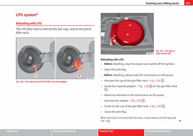
195Checking and refilling levels
LPG system*
Refuelling with LPG
The LPG filler neck is behind the fuel cap, next to the petrolfiller neck.
Fig. 128 Fuel tank open with LPG filler neck and adapter.
Fig. 129 LPG tank inspare wheel well
Refuelling with LPG
– Before refuelling, stop the engine and switch off the ignition.
– Open the tank flap.
– Before refuelling, please read the instructions on the pump.
– Unscrew the cap of the gas filler neck ⇒ fig. 128 1 .
– Screw the required adapter ⇒ fig. 128 2 on the gas filler neck1 .
– Refuel as indicated in the instructions on the pump.
– Unscrew the adapter ⇒ fig. 128 2 .
– Screw on the cap of the gas filler neck ⇒ fig. 128 1 .
– Close the tank flap.
When the hose is removed from the tank, a small amount of LPG may spillout ⇒ .
Safety First Operating Instructions Practical Tips Technical Specifications

196 Checking and refilling levels
The LPG tank ⇒ fig. 129 in the spare wheel well has a capacity of 52.8 litres.If the outside temperatures are very low, it may not be possible to complete-ly fill the LPG tank.
Pump attachments
There are a variety of types of LPG pump, and the methods of use may vary.Therefore, let the pump operator fill the tank when refuelling for the firsttime or fill from another pump.
Noises when refuelling with LPG
When refuelling with LPG, noises may be heard. These noises are insignifi-cant.
WARNING
Failure to refuel or handle LPG in the correct way could result in a fire,cause an explosion or lead to injuries.
● LPG is a highly explosive and inflammable substance. It may causesevere burns and other injury.
● Switch off the engine before refuelling.
● Always disconnect mobile phones and any other radiophony applian-ces, as electromagnetic waves may produce sparks and cause a fire.
● Do not remain in the vehicle while refuelling. If it is absolutely neces-sary to enter the vehicle, close the door and touch a metal surface beforetouching the attachment again. This will prevent the generation of staticelectricity and any possible fires while refuelling.
● Small quantities of LPG may leak out after refuelling. If LPG comes in-to contact with skin, there is a risk of freezing.
● Do not smoke and always keep bare flames away from the tank duringrefuelling. Failure to do so may lead to an explosion.
Adapter for the liquid petroleum gas (LPG) filler neck
An adapter is required due to the existence of a range ofpumps with different nozzles.
Fig. 130 General table of LPG filler neck adapters.
ACME adapter (adapter for Europe)
Dish Coupling Adapter (adapter for Italy)
Bayonet adapter
EURO adapter (adapter for Spain)
The supply includes the adapter for the country in question, the ACME 1 ,the Dish Coupling 2 , the bayonet 3 or the EURO adapter 4 .
The filler systems and corresponding adapters vary according to country. Aspetrol stations abroad do not always have the necessary adapters for yourLPG system, we recommend you purchase the appropriate adapter beforetravelling abroad. Check that the adapters are suited to your filling system.
1
2
3
4
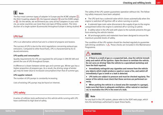
197Checking and refilling levels
NoteThe four most common types of adapter in Europe are the ACME adapter 1 ,the Dish Coupling adapter 2 , the bayonet adapter 3 and the EURO adapt-er 4 . On the whole, we recommend you carry all four adapters in your vehi-cle, as some countries use more than one type of filling system. The intro-duction of a single system (Euronozzle) throughout Europe is being studied.
LPG fuel
LPG is an alternative vehicle fuel and is a blend of propane and butane.
The success of LPG is due to the strict regulations concerning exhaust gasemissions. Compared to other fossil fuels, LPG is characterised by its re-duced emissions.
LPG quality and consumption
Quality requirements for LPG are regulated for all Europe in DIN EN 589 andpermit the use of LPG throughout Europe.
A difference is drawn between winter gas and summer gas. Winter gas has ahigher proportion of propane gas. As a result, the driving range of wintergas may be lower (due to increased consumption) than that of summer gas.
LPG supplier network
The number of LPG pumps is constantly increasing.
Lists of existing LPG pumps may be found on Internet.
LPG safety
A series of collision tests performed on this vehicle while running with LPGhave confirmed its high level of safety.
The safety of the LPG system guarantees operation without risk. The follow-ing safety measures have been adopted:
● The LPG tank has a solenoid valve which closes automatically when theengine is switched off (ignition off) or when running on petrol.
● A solenoid type main valve disconnects the supply of gas to the enginecompartment when the engine is switched off or running on petrol.
● A safety valve in the LPG tank with pipes to the outside prevents the gasfrom entering the vehicle interior.
● All anchorage points and materials have been designed to ensure themaximum possible levels of safety.
The condition of the LPG system should be checked regularly to guaranteesafe driving conditions ⇒ . These checks are included in the MaintenanceProgramme.
WARNING
● If there is a smell of gas or a suspected leak, stop the vehicle immedi-ately and switch off the ignition. Open the doors to ventilate the vehicle.Do not carry on driving! Take the vehicle to a specialised workshop andhave the fault repaired.
● Immediately extinguish any cigarettes and remove from the vehicleany objects which might produce a spark or cause a fire, and switch offimmediately if gas is smelt or a leak is detected.
● LPG tanks are subject to pressure and must be checked regularly. Theowner of the vehicle must check that these services are performed cor-rectly.
● When parking the vehicle in a closed area (for example in a garage),make sure that there is adequate ventilation, either natural or mechani-cal, to neutralise the LPG in the event of a leak.
NoteFor any fault in the LPG system, please refer to the SEAT web page, whichlists the workshops authorised to repair these faults.
Safety First Operating Instructions Practical Tips Technical Specifications
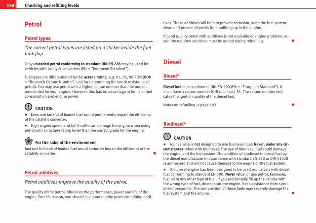
198 Checking and refilling levels
Petrol
Petrol types
The correct petrol types are listed on a sticker inside the fueltank flap.
Only unleaded petrol conforming to standard DIN EN 228 may be used forvehicles with catalytic converters (EN = “European Standard”).
Fuel types are differentiated by the octane rating, e.g: 91, 95, 98 RON (RON= “Research Octane Number”, unit for determining the knock resistance ofpetrol). You may use petrol with a higher octane number than the one rec-ommended for your engine. However, this has no advantage in terms of fuelconsumption and engine power.
CAUTION● Even one tankful of leaded fuel would permanently impair the efficiencyof the catalytic converter.
● High engine speed and full throttle can damage the engine when usingpetrol with an octane rating lower than the correct grade for the engine.
For the sake of the environmentJust one full tank of leaded fuel would seriously impair the efficiency of thecatalytic converter.
Petrol additives
Petrol additives improve the quality of the petrol.
The quality of the petrol influences the performance, power and life of theengine. For this reason, you should use good quality petrol containing addi-
tives. These additives will help to prevent corrosion, keep the fuel systemclean and prevent deposits from building up in the engine.
If good quality petrol with additives is not available or engine problems oc-cur, the required additives must be added during refuelling.
Diesel
Diesel*
Diesel fuel must conform to DIN EN 590 (EN = “European Standard”). Itmust have a cetane number (CN) of at least 51. The cetane number indi-cates the ignition quality of the diesel fuel.
Notes on refuelling ⇒ page 193.
Biodiesel*
CAUTION● Your vehicle is not designed to use biodiesel fuel. Never, under any cir-cumstances refuel with biodiesel. The use of biodiesel fuel could damagethe engine and the fuel system. The addition of biodiesel to diesel fuel bythe diesel manufacturer in accordance with standard EN 590 or DIN 51628is authorised and will not cause damage to the engine or the fuel system.
● The diesel engine has been designed to be used exclusively with dieselfuel conforming to standard EN 590. Never refuel or use petrol, kerosene,fuel oil or any other type of fuel. If you accidentally fill up the vehicle withthe wrong type of fuel, do not start the engine. Seek assistance from speci-alised personnel. The composition of these fuels may severely damage thefuel system and the engine.

199Checking and refilling levels
Winter driving
Diesel can thicken in winter.
Winter-grade diesel
When using “summer-grade diesel fuel”, difficulties may be experienced atsub-zero temperatures because the fuel thickens due to wax separation. Forthis reason, “winter-grade diesel fuel” is available in some countries duringthe cold months. It can be used at temperatures as low as -22 °C.
In countries with different climatic conditions the diesel fuel generally soldhas different temperature characteristics. Check with an Authorised ServiceCentre or filling stations in the country concerned regarding the type of die-sel fuels available.
Filter pre-heater
Your vehicle is fitted with a fuel filter glow plug system, making it wellequipped for operation in winter. This ensures that the fuel system remainsoperational to approx. -24 °C, provided you use winter-grade diesel that issafe to -15 °C.
However, if the fuel has waxed to such an extent that the engine will notstart at temperatures of under -24 °C, simply place the vehicle in a warmplace for a while.
CAUTIONDo not mix fuel additives (thinners or similar products) with diesel fuel.
Working in the engine compartment
Safety instructions on working in the engine compartment
Any work carried out in the engine compartment or on theengine must be carried out cautiously.
Before starting any work on the engine or in the engine compart-ment:
1. Switch off the engine and remove the key from the ignition.
2. Apply the handbrake.
3. Move the gear lever to neutral or the selector lever to position P.
4. Wait for the engine to cool down.
5. Keep children away from the vehicle.
6. Raise the bonnet ⇒ page 201.
You should not do any work in the engine compartment unless you know ex-actly how to carry out the jobs and have the correct tools! Have the work car-ried out by a specialised workshop if you are uncertain.
All service fluids and consumables, e.g. coolant, engine oil, spark plugsand batteries, are under constant development. SEAT provides a constantflow of information to the Authorised Service Centres concerning modifica-tions. For this reason, we recommend you to have service fluids and con-sumables replaced by an Authorised Service Centre. Please observe the rel-evant instructions ⇒ page 189. The engine compartment of the vehicle is ahazardous area. ⇒ .
Safety First Operating Instructions Practical Tips Technical Specifications

200 Checking and refilling levels
WARNING
All work on the engine or in the engine compartment, e.g. checking andrefilling fluids, involves the danger of injury and scalding as well as therisk of accident or fire.
● Never open the bonnet if you see steam, smoke or coolant escapingfrom the engine compartment. Otherwise, there is a risk of sustainingburns. Wait until no more steam or coolant is emitted, then allow the en-gine to cool before carefully opening the bonnet.
● Switch off the engine and remove the key from the ignition.
● Apply the handbrake and move the gear lever to neutral or selectorlever to position P.
● Keep children away from the vehicle.
● Never touch hot engine parts. There is a risk of burns.
● Never spill liquids on a hot engine or on a hot exhaust gas system.This is a fire hazard.
● Avoid causing short-circuits in the electrical system, particularly atthe points where the jump leads are attached ⇒ page 247. The batterycould explode.
● Never touch the radiator fan. It is temperature controlled and couldstart automatically, even when the engine has been switched off and thekey removed from the ignition!
● Do not unscrew the cap on the expansion tank when the engine ishot. If the coolant is hot, the cooling system will be pressurised!
● Protect face, hands and arms by covering the cap with a large, thickcloth to protect against escaping coolant and steam.
● Always make sure you have not left any objects, such as cleaningcloths and tools, in the engine compartment.
● If you have to work underneath the vehicle, you must use suitablestands additionally to support the vehicle, there is a risk of accident!. Ahydraulic jack is insufficient for securing the vehicle and there is a risk ofinjury.
WARNING (Continued)
● If any work has to be performed when the engine is started or withthe engine running, there is an additional, potentially fatal, safety riskfrom the rotating parts, such as the drive belts, alternator, radiator fan,etc., and from the high-voltage ignition system. You should also observethe following points:
– Never touch the electrical wiring of the ignition system.
– Ensure that jewellery, loose clothing and long hair do not get trap-ped in rotating engine parts. Danger of death. Before starting anywork remove jewellery, tie back and cover hair, and wear tight-fittingclothes.
– Never accelerate with a gear engaged without taking the necessaryprecautions. The vehicle could move, even if the handbrake is ap-plied. Danger of death.
● If work has to be carried out on the fuel system or on electrical com-ponents, you must observe the following safety notes in addition to theabove warnings:
– Always disconnect the battery. The vehicle must be unlocked whenthis is done, otherwise the alarm will be triggered.
– Do not smoke.
– Never work near naked flames.
– Always have a fire extinguisher on hand.
CAUTIONWhen topping up service fluids, make sure not to mistake them. Using thewrong fluids could cause serious malfunctions and engine damage!
For the sake of the environmentService fluids leaks are harmful to the environment. For this reason youshould make regular checks on the ground underneath your vehicle. If youfind spots of oil or other fluids, have your vehicle inspected in a specialisedworkshop.
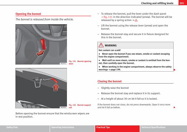
201Checking and refilling levels
Opening the bonnet
The bonnet is released from inside the vehicle.
Fig. 131 Bonnet openinglever
Fig. 132 Bonnet supportrod
Before opening the bonnet ensure that the windscreen wipers arein rest position.
– To release the bonnet, pull the lever under the dash panel⇒ fig. 131 in the direction indicated (arrow). The bonnet will bereleased by a spring action ⇒ .
– Lift the bonnet using the release lever (arrow) and open thebonnet.
– Release the bonnet stay and secure it in fixture designed forthis in the bonnet.
WARNING
Hot coolant can scald!
● Never open the bonnet if you see steam, smoke or coolant escapingfrom the engine compartment.
● Wait until no more steam, smoke or coolant is emitted from the bon-net, then carefully open the bonnet.
● When working in the engine compartment, always observe the safetywarnings ⇒ page 199.
Closing the bonnet
– Slightly raise the bonnet
– Release the bonnet stay and replace it in its support.
– At a height of about 30 cm let it fall so it is locked.
If the bonnet does not close, do not press downwards. Open it once moreand let it fall as before.
Safety First Operating Instructions Practical Tips Technical Specifications
202 Checking and refilling levels
WARNING
If the bonnet is not closed properly, it could open while you are drivingand completely obscure your view of the road. Risk of accident.
● After closing the bonnet, always check that it is properly secured. Thebonnet must be flush with the surrounding body panels.
● If you notice that the bonnet latch is not secured when the vehicle ismoving, stop the vehicle immediately and close the bonnet properly.Risk of accident.
Engine oil
General notes
The engine comes with a special, high quality, multi grade oil that can beused in all seasons of the year except for those regions affected by extremecold.
As the use of good quality oil is necessary for the correct operation and longservice life of the engine, when it becomes necessary to replenish orchange the oil, always use an oil that complies to the VW standards.
The specifications (VW standards) set out in the following page should ap-pear on the container of the service oil; when the container displays thespecific standards for petrol and diesel engines together, it means that theoil can be used for both types of engines.
We recommend that the oil change, indicated in the Maintenance Pro-gramme, be performed by an Authorised Service Centre or a specialisedworkshop.
The correct oil specifications for your engine are listed in ⇒ page 203, Oilproperties.
Service intervals
Service intervals can be flexible (LongLife service) or fixed (dependent ontime/distance travelled).
If the PR code that appears on the back of the Maintenance Programmebooklet is QG1, this means that your vehicle has the LongLife service pro-grammed. If it has the codes QG0 or QG2 the interval service is dependenton time/distance travelled.
Flexible service intervals (LongLife*)
Special oils and processes have been developed which, depending on thecharacteristics and individual driving profiles, allow to extend the oilchange service (LongLife service intervals).
Because this oil is essential for extending the service intervals, it must onlybe used observing the following indications:
● Avoid mixing it with oil for fixed service intervals.
● Only in exceptional circumstances, if the engine oil level is too low⇒ page 203 and LongLife oil is not available, it is permitted to top up(once) with oil for fixed service intervals ⇒ page 203 (up to a maximum of0.5 litres).
Fixed service intervals*
If your vehicle does not have the “LongLife service interval” or it has beendisabled (by request), you may use oils for fixed service intervals, which al-so appear in ⇒ page 203, Oil properties. In this case, your vehicle must beserviced after a fixed interval of 1 year / 15 000 km (whatever comes first)⇒ Booklet Maintenance Programme.
● In exceptional circumstances, if the engine oil level is too low⇒ page 203 and you cannot obtain the oil specified for your vehicle, youcan put in a small quantity of oil conforming to the specification ACEA A2 orACEA A3 (petrol engines) or ACEA B3 or ACEA B4 (diesel engines) (up to 0.5l).

203Checking and refilling levels
Vehicles with diesel particulate filter*
The “Maintenance Programme” states whether your vehicle is fitted with adiesel particulate filter.
Only VW 507 00 engine oil, with reduced ash formation, may be used in die-sel engines equipped with particulate filter. Using other types of oil willcause a higher soot concentration and reduce the life of the DPF. Therefore:
● Avoid mixing this oil with other engine oils.
● Only in exceptional circumstances, if the engine oil level is too low⇒ page 203 and you cannot obtain the oil specified for your vehicle, youcan use a small quantity of oil (once) conforming to the VW 506 00,VW 506 01, VW 505 00, VW 505 01 or ACEA B3 / ACEA B4 specification. (upto 0.5 l).
Oil properties
Engine type Specification
Petrol without flexible service in-terval
VW 502 00/ VW 504 00
Petrol with flexible service inter-val (LongLife)
VW 504 00
Diesel. Engines without Particu-late filter (DPF)
VW 505 01 / VW 506 01 / VW 507 00
Diesel. Particulate Filter Engines(DPF).With or without flexible serviceinterval (with and without Long-life)a)
VW 507 00
a) Only use recommended oils, otherwise you may damage the engine.
Engine oil additives
No type of additive should be mixed with the engine oil. The deteriorationcaused by these additives is not covered by the warranty.
NoteBefore a long trip, we recommend finding an engine oil that conforms to thecorresponding VW specifications and keeping it in the vehicle. This way, thecorrect engine oil will always be available for a top-up if needed.
Checking the engine oil level
The engine oil dipstick indicates the level of the oil.
Fig. 133 Engine oil dip-stick
Checking oil level
– Park the vehicle in a horizontal position.
– Briefly run the engine at idle speed until the service tempera-ture is reached and stop.
Safety First Operating Instructions Practical Tips Technical Specifications

204 Checking and refilling levels
– Wait two minutes.
– Pull out the dipstick. Wipe the dipstick with a clean cloth andinsert it again, pushing it in as far as it will go.
– Then pull it out once more and check the oil level ⇒ fig. 133.Top up with engine oil if necessary.
Oil level in area A
Do not add oil.
Oil level in area B
Oil can be topped up. The indicated oil level should be after in zone A
Oil level in area C
Oil must be topped up. The indicated oil level should be after in zoneA
Depending on how you drive and the conditions in which the vehicle isused, oil consumption can be up to 0.5 l/1000 km. Oil consumption is likelyto be higher for the first 5000 km. For this reason the engine oil level mustbe checked at regular intervals, preferably when filling the tank and beforea journey.
WARNING
Any work carried out in the engine compartment or on the engine mustbe carried out cautiously.
● When working in the engine compartment, always observe the safetywarnings ⇒ page 199.
CAUTIONIf the oil level is above the area A do not start the engine. This could resultin damage to the engine and catalytic converter. Contact an AuthorisedService Centre.
–
–
–
Topping up engine oil
Top up gradually with small quantities of oil.
Fig. 134 In the enginecompartment: Engine oilfiller cap
Before opening the bonnet, read and observe the warnings ⇒ inSafety instructions on working in the engine compartment onpage 199.
– Unscrew cap from oil filler opening ⇒ fig. 134.
– Top-up oil in small amounts, using the correct oil.
– To avoid over-filling with engine oil, you should top-up usingsmall quantities, wait a while and check the oil level beforeadding any more oil.
– As soon as the oil level is in area B , carefully close the cap.
The position of the oil filler opening is shown in the corresponding enginecompartment illustration ⇒ page 256.

205Checking and refilling levels
Engine oil specification ⇒ page 203.
WARNING
Oil is highly inflammable! Ensure that no oil comes into contact with hotengine components when topping up.
CAUTIONIf the oil level is above the area A do not start the engine. This could resultin damage to the engine and catalytic converter. Contact a specialised work-shop.
For the sake of the environmentThe oil level must never be above area A . Otherwise oil can be drawn inthrough the crankcase breather and escape into the atmosphere via the ex-haust system.
Changing engine oil
The engine oil must be changed at the intervals given in theservice schedule.
We recommend that you have the engine oil changed by an AuthorisedService Centre.
The oil change intervals are shown in the Maintenance Programme.
WARNING
Only change the oil yourself if you have the specialist knowledge re-quired!
● Before opening the bonnet, read and observe the warnings⇒ page 199, Safety instructions on working in the engine compartment.
● Wait for the engine to cool down. Hot oil may cause burn injuries.
● Wear eye protection to avoid injuries caused by splashes of oil.
● When removing the oil drain plug with your fingers, keep your armhorizontal to help prevent oil from running down your arm.
● Wash your skin thoroughly if it comes into contact with engine oil.
● Engine oil is poisonous! Used oil must be stored in a safe place out ofthe reach of children.
CAUTIONNo additives should be used with engine oil. This could result in enginedamage. Any damage caused by the use of such additives would not becovered by the factory warranty.
For the sake of the environment● Because of the disposal problems, the necessary special tools and spe-cialist knowledge required, we recommend that you have the engine oil andfilter changed by an Authorised Service Centre.
● Never pour oil down drains or into the ground.
● Use a suitable container when draining the used oil. It must be largeenough to hold all the engine oil.
Safety First Operating Instructions Practical Tips Technical Specifications

206 Checking and refilling levels
Coolant
Coolant specifications
Coolant is a mixture of water and at least 40% coolant addi-tive.
The cooling system must be filled with a mixture of water and at least 40 %of our coolant additive G 12++ or an additive with the specification TT-VW774 G (known for its purple colour). This mixture gives the necessary frostprotection down to -25 °C and protects the alloy parts of the cooling systemagainst corrosion. It also prevents scaling and raises the boiling point of thecoolant.
The concentration of coolant must always be at least 40% - even if freezeprotection is not required.
If greater freeze protection is required in very cold climates, the proportionof the antifreeze additive G 12++ can be increased. However, the percent-age of coolant additives should not exceed 60%, as this would reduce thefreeze protection. It would also reduce the cooling effect. A mixture with60% coolant additive will give frost protection to approx. -40 °C.
WARNING
● The coolant additive is toxic. There is a toxic risk. Always keep thecoolant additive in the original container which should be stored out ofthe reach of children. The same applies to coolant which you havedrained off.
● The coolant additive G 12++ must be added in sufficient quantities toprovide anti-freeze protection at the coldest ambient temperatures thatcan be expected. At extremely cold outside temperatures, the coolantcould freeze, causing the vehicle to breakdown. As the heater would notwork either, there is a risk of freezing to death.
CAUTION● Other additives may give considerably inferior corrosion protection. Theresulting corrosion in the cooling system can lead to a loss of coolant, caus-ing serious damage to the engine.
● If additive G12++ is not available, this can be mixed with G12+, bearingin mind that the protection against corrosion will be reduced.
Checking the coolant level and topping up
The correct coolant level is important for fault-free function-ing of the engine cooling system.
Fig. 135 In the enginecompartment: Coolantexpansion tank cap
Before opening the bonnet, read and observe the warnings ⇒ inSafety instructions on working in the engine compartment onpage 199.

207Checking and refilling levels
Opening the coolant expansion tank
– Switch off the engine and allow it to cool.
– To prevent scalding, cover the cap on the expansion tank with athick cloth and carefully unscrew the cap ⇒ .
Checking coolant level
– Look into the open coolant expansion tank and read off thecoolant level.
– If the level is below the “MIN” mark, top up with coolant.
Topping up coolant
– Only use new coolant liquid.
– Do not fill above the “MAX” mark.
Closing the coolant expansion tank
– Screw the cap on again tightly.
The position of the coolant expansion reservoir is shown in the correspond-ing engine compartment illustration ⇒ page 256.
Ensure the coolant conforms to the required specifications. Do not use a dif-ferent type of additive if additive G 12++ is not available. In this case useonly water and bring the coolant concentration back up to the correct levelas soon as possible by putting in the specified additive.
Always top up with new coolant.
Do not fill above the “MAX” mark. Otherwise the excess coolant will beforced out of the cooling system when the engine is hot.
The additive G 12++ can be mixed with the G 12+ in any proportion.
WARNING
Any work carried out in the engine compartment or on the engine mustbe carried out cautiously.
● When working in the engine compartment, always observe the safetywarnings ⇒ page 199.
● When the engine is warm or hot, the cooling system is pressurised!Do not unscrew the cap on the expansion tank when the engine is hot.This is a burn injury risk.
CAUTION● If you notice a change in the colour of the liquid because it has been inuse for a long time, it is recommended to change it, as it will have lost someof its properties and could cause damage to the vehicle.
● If a lot of coolant fluid has been lost, wait for the engine to cool downbefore putting in cold coolant. This avoids damaging the engine. Large cool-ant losses are an indication of leaks in the cooling system. See a special-ised workshop immediately and have the cooling system checked. Other-wise, there is a risk of engine damage.
Safety First Operating Instructions Practical Tips Technical Specifications

208 Checking and refilling levels
Washer fluid and windscreen wiper blades
Topping up washer fluid
The water for cleaning the windscreen should always bemixed with washer fluid.
Fig. 136 In the enginecompartment: Cap ofwindscreen washer fluidreservoir.
The windscreen washer and the headlight washers are supplied with fluidfrom the windscreen washer fluid container in the engine compartment. Thecontainer holds approx. 2 litres; in vehicles with headlight washers* it holdsapprox. 4.5 litres.
The tank is in the engine compartment.
Plain water is not enough to clean the windscreen and headlights. We rec-ommend that you always add a product to the windscreen washer fluid. Ap-proved windscreen cleaning products exist on the market with high deter-gent and anti-freeze properties, these may be added all-year-round. Pleasefollow the dilution instructions on the packaging.
WARNING
Any work carried out in the engine compartment or on the engine mustbe carried out cautiously.
● When working in the engine compartment, always observe the safetywarnings ⇒ page 199.
CAUTION● Never put radiator anti-freeze or other additives into the windscreenwasher fluid.
● Always use approved windscreen cleansing products diluted as per in-structions. If you use other washer fluids or soap solutions, the tiny holes inthe fan-shaped nozzles could become blocked.

209Checking and refilling levels
Changing windscreen wiper blades
If the windscreen wiper blades are in perfect condition, youwill benefit from an improved visibility. Damaged wiperblades should be replaced immediately.
Fig. 137 Windscreenwipers in service position
Fig. 138 Change wind-screen wiper blade
To change the blades it is necessary to change the rest position ofthe wipers to the service position.
Do not change the windscreen wipers when out of the service posi-tion, as it could cause paint to flake off the bonnet due to frictionwith the windscreen wiper arm.
Service position (For changing wiper blades)
– Ensure that the wiper blades are not frozen.
– Turn ignition on and off and then (before approx. 9 sec.) movethe windscreen wiper lever to the intermittent wipe position.The windscreen wipers will move to the service position⇒ fig. 137.
Removing the wiper blade
– Lift the windscreen wiper arm.
– Press on the securing tab ⇒ fig. 138.
– Extract the wiper blade from the wiper arm.
Fitting the wiper blade
– Insert the wiper blade onto the windscreen wiper arm until itclicks into place.
– Place the wiper arms to their initial position.
If the windscreen wipers smear, they should be replaced if they are dam-aged, or cleaned if they are soiled.
If this does not produce the desired results, the setting angle of the wind-screen wiper arms might be incorrect. They should be checked by a special-ised workshop and corrected if necessary.
Safety First Operating Instructions Practical Tips Technical Specifications

210 Checking and refilling levels
WARNING
Do not drive unless you have good visibility through all windows!
● Clean the windscreen wiper blades and all windows regularly.
● The wiper blades should be changed once or twice a year.
CAUTION● Damaged or dirty windscreen wipers could scratch the windscreen.
● Never use fuel, nail varnish remover, paint thinner or similar products toclean the windows. This could damage the windscreen wiper blades.
● Never move the windscreen wiper or windscreen wiper arm manually.This could cause damage.
● To avoid damage to the bonnet and the windscreen wiper arms, the lat-ter should only be lifted off the windscreen when in service position.
Note● The wiper arms can be moved to the service position only when the bon-net is properly closed.
● You can also use the service position, for example, if you want to fix acover over the windscreen in the winter to keep it clear of ice.
Changing the rear wiper blade
A good rear wiper blade is essential for clear rear vision.Damaged wiper blades should be replaced immediately.
Fig. 139 Removing therear window wiper blade
Fig. 140 Fitting the rearwindow wiper blade

211Checking and refilling levels
Removing the wiper blade
– Lift the wiper arm away from the glass ⇒ fig. 139.
– Slide the blade adapter in the direction of the arrow and removethe blade ⇒ fig. 139.
Fitting the wiper blade
– With one hand, hold the top end of the wiper arm.
– Place the blade as shown in the ⇒ fig. 140 and slide the adapt-er along until it engages.
Check the condition of the wiper blade regularly. Change as required.
If the windscreen wiper scrapes, it should be replaced if damaged, orcleaned if soiled.
If this is not sufficient, refer to a specialised workshop.
WARNING
Do not drive unless you have good visibility through all windows!
● Clean the windscreen wiper blades and all windows regularly.
● The wiper blades should be changed once or twice a year.
CAUTION● A damaged or dirty window wiper could scratch the rear window.
● Never use fuel, nail varnish remover, paint thinner or similar products toclean the window.
● Never move the windscreen wiper by hand. This could cause damage.
Brake fluid
Checking the brake fluid level
The brake fluid is checked at the intervals given in the serv-ice schedule.
Fig. 141 In the enginecompartment: Brake fluidreservoir cover
– Read off the fluid level at the transparent brake fluid reservoir. Itshould always be between the “MIN” and “MAX” marks.
The position of the brake fluid reservoir is shown in the corresponding en-gine compartment illustration ⇒ page 256. The brake fluid reservoir has ablack and yellow cap.
The brake fluid level drops slightly when the vehicle is being used as thebrake pads are automatically adjusted as they wear.
However, if the level goes down noticeably in a short time, or drops belowthe “MIN” mark, there may be a leak in the brake system. A display on theinstrument panel will warn you if the brake fluid level is too low ⇒ page 63.
Safety First Operating Instructions Practical Tips Technical Specifications

212 Checking and refilling levels
WARNING
Before opening the bonnet to check the brake fluid level, read and ob-serve the warnings ⇒ page 199.
Changing the brake fluid
The Maintenance Programme indicates the brake fluidchange intervals.
We recommend that you have the brake fluid changed by an AuthorisedService Centre.
Before opening the bonnet, please read and follow the warnings ⇒ inSafety instructions on working in the engine compartment on page 199 insection “Safety notes for working in the engine compartment”.
Brake fluid absorbs moisture. In the course of time, it will absorb water fromthe ambient air. If the water content in the brake fluid is too high, the brakesystem could corrode. This also considerably reduces the boiling point ofthe brake fluid. Heavy use of the brakes may then cause a vapour lockwhich could impair the braking effect.
It is important that you use only brake fluid compliant with US standardFMVSS 116 DOT 4. We recommend the use of Genuine SEAT brake fluid.
WARNING
Brake fluid is poisonous. Old brake fluid impairs the braking effect.
● Before opening the bonnet to check the brake fluid level, read and ob-serve the warnings ⇒ page 199.
WARNING (Continued)
● Brake fluid should be stored in the closed original container in a safeplace out of reach of children. There is a toxic risk.
● Complete the brake fluid change according to the Maintenance Pro-gramme. Heavy use of the brakes may cause a vapour lock if the brakefluid is left in the system for too long. This would seriously affect the effi-ciency of the brakes and the safety of the vehicle. This may cause an ac-cident.
CAUTIONBrake fluid could damage the paintwork. Wipe off any brake fluid from thepaintwork immediately.
For the sake of the environmentThe brake pads and fluid must be collected and disposed of according theapplicable regulations. The SEAT Technical Service network has the neces-sary equipment and qualified personnel for collecting and disposing of thiswaste material.

213Checking and refilling levels
Vehicle battery
Warnings on handling the battery
Wear eye protection
Battery acid is very corrosive and caustic. Wear protective glovesand eye protection!
Fires, sparks, open flames and smoking are prohibited!
A highly explosive mixture of gases is released when the batteryis under charge.
Keep children away from acid and batteries!
WARNING
Always be aware of the danger of injury and chemical burns as well asthe risk of accident or fire when working on the battery and the electricalsystem:
● Wear eye protection. Protect your eyes, skin and clothing from acidand particles containing lead.
● Battery acid is very corrosive and caustic. Wear protective gloves andeye protection. Do not tilt the batteries. This could spill acid through thevents. Rinse battery acid from eyes immediately for several minutes withclear water. Then seek medical care immediately. Neutralise any acidsplashes on the skin or clothing with a soapy solution, and rinse off withplenty of water. If acid is swallowed by mistake, consult a doctor immedi-ately.
WARNING (Continued)
● Fires, sparks, open flames and smoking are prohibited. When han-dling cables and electrical equipment, avoid causing sparks and electro-static charge. Never short the battery terminals. High-energy sparks cancause injury.
● A highly explosive mixture of gases is released when the battery isunder charge. The batteries should be charged in a well-ventilated roomonly.
● Keep children away from acid and batteries.
● Before working on the electrical system, you must switch off the en-gine, the ignition and all consumers. The negative cable on the batterymust be disconnected. When a light bulb is changed, you need onlyswitch off the light.
● Deactivate the anti-theft alarm by unlocking the vehicle before youdisconnect the battery! The alarm will otherwise be triggered.
● When disconnecting the battery from the vehicle electrical system,disconnect first the negative cable and then the positive cable.
● Switch off all electrical consumers before reconnecting the battery.Reconnect first the positive cable and then the negative cable. Never re-verse the polarity of the connections. This could cause an electrical fire.
● Never charge a frozen battery, or one which has thawed. This couldresult in explosions and chemical burns. Always replace a battery whichhas frozen. A flat battery can freeze at temperatures around 0 °C.
● Ensure that the vent hose is always connected to the battery.
● Never use a defective battery. This could cause an explosion. Replacea damaged battery immediately.
● For vehicles with the battery in the luggage compartment: Check thatthe battery gas ventilation hose is securely attached.
Safety First Operating Instructions Practical Tips Technical Specifications

214 Checking and refilling levels
CAUTION● Never disconnect the battery if the ignition is switched on or if the en-gine is running. This could damage the electrical system or electronic com-ponents.
● Do not expose the battery to direct sunlight over a long period of time,as the intense ultraviolet radiation can damage the battery housing.
● If the vehicle is left standing in cold conditions for a long period, protectthe battery from freezing. If it freezes it will be damaged.
Checking the electrolyte level
The electrolyte level should be checked regularly in high-mileage vehicles, in hot countries and in older batteries.
– Open the engine bonnet and the battery cover ⇒ in Safety in-structions on working in the engine compartment on page 200⇒ in Warnings on handling the battery on page 213.
– Check the colour display in the "magic eye" on the top of thebattery.
– If there are air bubbles in the window, tap the window gentlyuntil they disperse.
The position of the battery is shown in the corresponding engine compart-ment diagram ⇒ page 256.
The “magic eye” indicator, located on the top of the battery changes colour,depending on the charge state and electrolyte level of the battery.
There are two different colours:
● Black: correct charge status.
● Transparent/clear yellow: the battery must be replaced. Contact a spe-cialist workshop.
Charging and changing the vehicle battery
The battery is maintenance-free and is checked during theinspection service. All work on the vehicle battery requiresspecialist knowledge.
If you often drive short distances or if the vehicle is not driven for long peri-ods, the battery should be checked by a specialised workshop between thescheduled services.
If the battery has discharged and you have problems starting the vehicle,the battery might be damaged. If this happens, we recommend you havethe vehicle battery checked by an Authorised Service Centre where it will bere-charged or replaced.
Charging the battery
The vehicle battery should be charged by a specialised workshop only, asbatteries using special technology have been installed and they must becharged in a controlled environment.
Replacing a vehicle battery
The battery has been developed to suit the conditions of its location andhas special safety features.
Genuine SEAT batteries fulfil the maintenance, performance and safetyspecifications of your vehicle.

215Checking and refilling levels
WARNING
● We recommend you use only maintenance-free or cycle free leak-proofbatteries which comply with standards T 825 06 and VW 7 50 73. Thisstandard applies as of 2001.
● Before starting any work on the batteries, you must read and observethe warnings ⇒ in Warnings on handling the battery on page 213.
For the sake of the environmentBatteries contain toxic substances such as sulphuric acid and lead. Theymust be disposed of appropriately and must not be disposed of with ordi-nary household waste.
Wheels
General notes
Avoiding damage
– If you have to drive over a kerb or similar obstacle, drive veryslowly and at a right angle.
– Keep grease, oil and fuel off the tyres.
– Inspect the tyres regularly for damage (cuts, cracks or blisters,etc.). Remove any foreign objects embedded in the treads.
Storing tyres
– When you remove the tyres, mark them in order to maintain thesame direction of rotation when they are installed again.
– When removed, the wheels and/or tyres should be stored in acool, dry and preferably dark location.
– Store tyres in a vertical position if they are not fitted on wheelrims.
New tyres
New tyres must be run in ⇒ page 172.
The tread depth of new tyres may vary, according to the type and make oftyre and the tread pattern.
Concealed damage
Damage to tyres and rims is often not readily visible. If you notice unusualvibrations or the vehicle pulling to one side, this may indicate that one ofthe tyres is damaged. The tyres should be checked immediately by an Au-thorised Service Centre.
Tyres with directional tread pattern
An arrow on the tyre sidewall indicates the direction of rotation on tyres withdirectional tread. Always observe the direction of rotation indicated whenfitting the wheel. This guarantees optimum grip and helps to avoid aqua-planing, excessive noise and wear.
WARNING
● New tyres do not have maximum grip during the first 500 km. Driveparticularly carefully to avoid possible accidents.
● Never drive with damaged tyres. This may cause an accident.
● If you notice unusual vibrations or if the vehicle pulls to one sidewhen driving, stop the vehicle immediately and check the tyres for dam-age.
Safety First Operating Instructions Practical Tips Technical Specifications

216 Checking and refilling levels
Checking tyre pressure
The correct tyre pressure can be seen on the sticker on theinside of the tank flap.
1. Read the required tyre inflation pressure from the sticker. Thevalues refer to Summer tyres.
2. The tyre pressures should only be checked when the tyres arecold. The slightly raised pressures of warm tyres must not be re-duced.
3. Adjust the tyre pressure to the load you are carrying.
Tyre pressure
The correct tyre pressure is especially important at high speeds. The pres-sure should therefore be checked at least once a month and before startinga journey.
WARNING
A tyre can easily burst if the pressure is too low, causing an accident!
● At continuously high speeds, a tyre with insufficient pressure flexesmore. In this way it becomes too hot, and this can cause tread separationand tyre blow-out. Always observe the recommended tyre pressures.
● If the tyre pressure is too low or too high, the tyres will wear prema-turely and the vehicle will not handle well. Risk of accident!
For the sake of the environmentUnder-inflated tyres will increase fuel consumption.
Tyre service life
The service life of tyres is dependent on tyre pressure, driv-ing style and fitting.
Fig. 142 Tyre tread wearindicators
Fig. 143 Diagram forchanging wheels
217Checking and refilling levels
Wear indicators
The original tyres on your vehicle have 1.6 mm high “tread wear indicators”⇒ fig. 142, running across the tread. Depending on the make, there will be6 to 8 of them evenly spaced around the tyre. Markings on the tyre sidewall(for instance the letters “TWI” or other symbols) indicate the positions ofthe tread wear indicators. The minimum tread depth required by law is1.6 mm (measured in the tread grooves next to the tread wear indicators).Worn tyres must be replaced. Different figures may apply in export countries⇒ .
Tyre pressure
Incorrect tyre pressure causes premature wear and could cause tyre blow-out. For this reason, the tyre pressure should be checked at least once permonth ⇒ page 216.
Driving style
Fast cornering, heavy acceleration and hard braking all increase tyre wear.
Changing wheels around
If the front tyres are worn considerably more than the rear ones it is advisa-ble to change them around as shown ⇒ fig. 143. All the tyres will then lastfor about the same time.
Wheel balance
The wheels on new vehicles are balanced. However, various factors encoun-tered in normal driving can cause them to become unbalanced, which re-sults in steering vibration.
Unbalanced wheels should be rebalanced, as they otherwise cause exces-sive wear on steering, suspension and tyres. A wheel must also be reba-lanced when a new tyre is fitted.
Incorrect wheel alignment
Incorrect wheel alignment causes excessive tyre wear, impairing the safetyof the vehicle. If tyres show excessive wear, you should have the wheelalignment checked by an Authorised Service Centre.
WARNING
There is a serious danger of accidents if a tyre bursts during driving!
● The tyres must be replaced at the latest when the tread wear indica-tors are worn ⇒ page 217. Failure to do so could result in an accident.Worn tyres do not grip well at high speeds on wet roads. There is also agreater risk of aquaplaning.
● At continuously high speeds, a tyre with insufficient pressure flexesmore. This causes it to overheat. This can cause tread separation and tyreblow-out. Risk of accident. Always observe the recommended tyre pres-sures.
● If tyres show excessive wear, you should have the running gearchecked by an Authorised Service Centre.
● Keep chemicals such as oil, fuel and brake fluid away from tyres.
● Damaged wheels and tyres must be replaced immediately!
For the sake of the environmentUnder-inflated tyres will increase fuel consumption.
New tyres and wheels
New tyres and wheels have to be run in.
The tyres and wheel rims are an essential part of the vehicle's design. Thetyres and rims approved by SEAT are specially matched to the characteris-tics of the vehicle and make a major contribution to good road holding andsafe handling ⇒ .
Tyres should be replaced at least in pairs and not individually (i.e. both fronttyres or both rear tyres together). A knowledge of tyre designations makes iteasier to choose the correct tyres. Radial tyres have the tyre designationsmarked on the sidewall, for example:
Safety First Operating Instructions Practical Tips Technical Specifications

218 Checking and refilling levels
195/65 R15 91T
This contains the following information:
Tyre width in mm
Height/width ratio in %
Tyre construction: Radial
Rim diameter in inches
Load rating code
Speed rating
The tyres could also have the following information:
● A direction of rotation symbol
● “Reinforced” denotes heavy-duty tyres.
The manufacturing date is also indicated on the tyre sidewall (possibly onlyon the inner side of the wheel).
“DOT ... 1103 ...” means, for example, that the tyre was produced in the11th week of 2003.
We recommend that work on tyres and wheels be carried out by an Author-ised Service Centre. They are familiar with the procedure and have the nec-essary special tools and spare parts as well as the proper facilities for dis-posing of the old tyres.
Any Authorised Service Centre has full information on the technical require-ments when installing or changing tyres, wheels or wheel trims.
195
65
R
15
91
T
WARNING
● We recommend that you use only wheels and tyres which have beenapproved by SEAT for your model. Failure to do so could impair vehiclehandling. Risk of accident.
● Avoid running the vehicle on tyres that are more than 6 years old. Ifyou have no alternative, you should drive slowly and with extra care at alltimes.
● Never use old tyres or those with an unknown history of use.
● If wheel trims are retrofitted, you must ensure that the flow of air tothe brakes is not restricted. This could cause them to overheat.
● All four wheels must be fitted with radial tyres of the same type, size(rolling circumference) and the same tread pattern.
For the sake of the environmentOld tyres must be disposed of according to the laws in the country con-cerned.
Note● For technical reasons, it is not generally possible to use the wheels fromother vehicles. This can also apply to wheels of the same model. The use ofwheels or tyres which have not been approved by SEAT for use with yourmodel may invalidate the vehicle's type approval for use on public roads.
● If the spare tyre is not the same as the tyres that are mounted on thevehicle (e.g. winter tyres) you should only use the spare tyre for a short peri-od of time and drive with extra care. Refit the normal road wheel as soon aspossible.

219Checking and refilling levels
Wheel bolts
Wheel bolts must be tightened to the correct torque.
The design of wheel bolts is matched to the rims. If different wheel rims arefitted, the correct wheel bolts with the right length and correctly shapedbolt heads must be used. This ensures that wheels are fitted securely andthat the brake system functions correctly.
In certain circumstances, you should not use wheel bolts from a differentvehicle, even if it is the same model ⇒ page 189.
WARNING
If the wheel bolts are not tightened correctly, the wheel could becomeloose while driving. Risk of accident.
● The wheel bolts must be clean and turn easily. Never apply grease oroil to them.
● Use only wheel bolts which belong to the wheel.
● If the prescribed torque of the wheel bolts is too low, they could loos-en whilst the vehicle is in motion. Risk of accident! If the tightening tor-que is too high, the wheel bolts and threads can be damaged.
CAUTIONThe prescribed torque for wheel bolts for steel and alloy wheels is 120 Nm.
Winter tyres
Winter tyres will improve the vehicles handling on snow andice.
In winter conditions winter tyres will considerably improve the vehicle's han-dling. The design of summer tyres (width, rubber compound, tread pattern)gives less grip on ice and snow.
Winter tyres must be inflated to a pressure 0.2 bar higher than the pres-sures specified for summer tyres (see sticker on tank flap).
Winter tyres must be fitted on all four wheels.
Information on permitted winter tyre sizes can be found in the vehicle's reg-istration documents. Use only radial winter tyres. All tyre sizes listed in thevehicle documentation also apply to winter tyres.
Winter tyres lose their effectiveness when the tread is worn down to a depthof 4 mm.
The speed rating code ⇒ page 217, New tyres and wheels determines thefollowing speed limits for winter tyres: ⇒
Q max. 160 km/h
S max. 180 km/h
T max. 190 km/h
H max. 210 km/h
In some countries, vehicles which can exceed the speed rating of the fittedtyre must have an appropriate sticker in the driver's field of view. Thesestickers are available from your Authorised Service Centre. The legal require-ments of each country must be followed.
Do not have winter tyres fitted for unnecessarily long periods. Vehicles withsummer tyres handle better when the roads are free of snow and ice.
Safety First Operating Instructions Practical Tips Technical Specifications

220 Checking and refilling levels
If you have a flat tyre, please refer to the notes on the spare wheel⇒ page 217, New tyres and wheels.
WARNING
The maximum speed for the winter tyres must not be exceeded. Other-wise, this could lead to tyre damage and risk of accident.
For the sake of the environmentFit your summer tyres again as soon as possible. They are quieter, do notwear so quickly and reduce fuel consumption.
Snow chains
Snow chains may be fitted only to the front wheels, and only for the follow-ing tyres:
175/70R14185/60R15
Chains with links not exceeding 15 mm (including the chainclosure)
215/45R16 Chains with links not exceeding 9 mm (including the chainclosure)
215/40R17 Chains with links not exceeding 7 mm (including the chainclosure)
Remove wheel hub covers and trim rings before fitting snow chains. Forsafety reasons cover caps, available in any Authorised Service Centre, mustthen be fitted over the wheel bolts.
WARNING
Snow chains should be correctly tightened in accordance with the manu-facturer's instructions. This will prevent the chains coming into contactwith the wheel housing.
CAUTIONRemove the snow chains to drive on roads without snow. Otherwise theywill impair handling, damage the tyres and wear out very quickly.
NoteIn some countries, the speed limit for using snow chains is 50 km/h. Thelegal requirements of the country should be followed.

221If and when
If and when
Vehicle tools, spare wheel
Vehicle Tools
The vehicle onboard tools are located under the floor panelin the luggage compartment.
– Lift floor panel
– Take the on-board tools out of the vehicle.
The tool kit includes:
● Jack*
● Hook to remove integral* trim and screw caps.
● Box spanner for wheel bolts*
● Towing ring*
● Adapter for the anti-theft wheel bolts*
Some of the items listed are only provided in certain model versions, or areoptional extras.
WARNING
● The factory-supplied jack is only designed for changing wheels onthis model. On no account attempt to use it for lifting heavier vehicles orother loads. Risk of injury.
● Use the jack only on a firm, level ground.
WARNING (Continued)
● Never start the engine when the vehicle is on the jack. Risk of acci-dent.
● If work is to be carried out underneath the vehicle, this must be se-cured by suitable means. Otherwise, there is a risk of injury.
Spare wheel (emergency wheel)*
The spare wheel (emergency wheel) must only be used forthe minimum necessary time.
The temporary spare wheel is stored under the floor panel in the luggagecompartment and is attached by a thumbnut.
How to use the temporary spare wheel
If you ever have a punctured tyre or loss of pressure, the emergency wheelis only intended for temporary use until you reach a workshop. Change it fora duty wheel as soon as possible.
Please note the following restrictions when using the temporary sparewheel. This spare wheel has been specially designed for your vehicle, thus,it cannot be changed with the spare wheel from another vehicle.
No other type of tyre (normal summer or winter tyre) may be fitted on thecompact temporary spare wheel rim.
Snow chains
For technical reasons, snow chains must not be used on the compact tem-porary spare wheel.
Safety First Operating Instructions Practical Tips Technical Specifications

222 If and when
If you have a puncture on one of the front wheels when using snow chains,fit the compact temporary spare in place of one of the rear wheels. You canthen attach the snow chains to the wheel taken from the rear and use thiswheel to replace the punctured front wheel.
WARNING
● The tyre pressures must be checked and corrected as soon as possi-ble.
● Do not drive faster than 80 km/h. Higher speeds can cause an acci-dent.
● Avoid heavy acceleration, hard braking and fast cornering. Risk of ac-cident.
● Never use two or more compact spare tyres at the same time, risk ofaccident.
● No other type of tyre (normal summer or winter tyre) may be fitted onthe compact temporary spare wheel rim.
Tyre repair kit*
The tyre repair kit (for vehicles not including a spare wheel)is stored under the floor panel in the luggage compartment.
Your vehicle is equipped with the Tyre Mobility System “Tyre repair kit”.
The tyre repair kit consists of a container with sealing compound to repairthe puncture and a compressor to generate the required tyre pressure. Thekit will reliably seal punctures up to a size of about 4 mm caused by thepenetration of a foreign body into the tyre.
Note● Seek professional assistance if the repair of a tyre puncture is not possi-ble with the sealing compound.
Wheel change
Preparation work
What you must do before changing a wheel.
– If you have a flat tyre or puncture, park the vehicle as far awayfrom the flow of traffic as possible. Choose a location that is aslevel as possible.
– All passengers should leave the vehicle. They should wait in asafe area (for instance behind the roadside crash barrier).
– Switch the engine off. Switch the hazard warning lights on andplace the warning triangles in position.
– Apply the handbrake firmly.
– Engage the first gear, or put the selector lever to position P forthose vehicles with an automatic gearbox.
– If you are towing a trailer, unhitch it from your vehicle.
– Take the vehicle tools and the spare wheel out of the luggagecompartment.
WARNING
Switch on the hazard warning lights and place the warning triangles inposition. This is for your own safety and also warns other road users.

223If and when
CAUTIONIf you have to change the wheel on a slope, it is essential to lock the parallelwheel on the same axle as that to be changed, with a wedge or similar inorder to immobilise the vehicle.
NotePlease observe legal requirements when doing so.
Changing a wheel
Change the wheel as described below
– Remove the hub caps or the integral trim.
– Slacken the wheel bolts.
– Raise the car with the jack at the corresponding point.
– Remove the wheel and then fit the spare wheel.
– Lower the vehicle.
– Tighten the wheel bolts firmly with the box spanner.
– Replace the hub cap.
After changing a wheel
After changing the wheel there are still tasks to complete.
– Put the tools and jack back in the luggage compartment.
– Place the wheel with the defective tyre in the luggage compart-ment and secure it.
– Check the tyre pressure of the newly fitted tyre as soon as pos-sible.
– Have the tightening torque of the wheel bolts checked as soonas possible with a torque wrench. The prescribed torque mustbe 120 Nm.
Note● If you notice that the wheel bolts are corroded and difficult to turn whenchanging a wheel, they must be replaced before having the wheel bolt tor-que checked.
● For safety reasons, drive at moderate speeds until the wheel bolt tight-ening torque has been checked.
Safety First Operating Instructions Practical Tips Technical Specifications

224 If and when
Wheel covers*
The wheel covers must be removed for access to the wheelbolts
Fig. 144 Remove thecomplete hub cap
Removing
– Remove the wheel cover using the wire hook ⇒ fig. 144.
– Hook this into one of the cut-outs of the wheel cover.
Fitting
– Fit the wheel cover onto the wheel rim by pressing it firmly. Putpressure initially on the point of the cut-out for the valve. Nextfit the rest of the hubcap
Loosening the wheel bolts
The wheel bolts must be loosened before raising the vehicle.
Fig. 145 Changing thewheel: loosen the wheelbolts
Loosening
– Fit the box spanner as far as it will go over the wheel bolt.
– Grasp the box spanner by the end turn it about one full turn tothe left ⇒ fig. 145.
Tightening
– Fit the box spanner as far as it will go over the wheel bolt.
– Grasp the box spanner close to the end and turn the bolt to theright until it is secured.
– An adapter is required to unscrew or tighten the anti-theftwheel bolts.

225If and when
WARNING
Loosen the wheel bolts only about one turn before raising the vehiclewith the jack, otherwise there is a risk of accident.
Note● If the wheel bolt is very tight, you may be able to loosen it by pushingdown the end of the spanner carefully with your foot. Hold on to the vehiclefor support and take care not to slip.
Raising the vehicle
In order to remove the wheel, the vehicle must be raisedwith a jack.
Fig. 146 Jack positionpoints
Fig. 147 Fitting the jack
– Locate the jacking point under the door sill closest to the wheelto be changed ⇒ fig. 146.
– Place the jack under the jacking point and turn the crank untilthe arm of the jack is directly below the vertical rib under thedoor sill.
– Align the jack so that the arm of the jack fits around the rib un-der the door sill and the movable base plate of the jack is flaton the ground ⇒ fig. 147.
– Raise the jack until the defective wheel is just clear of theground.
Recesses at the front and rear of the door sills mark the jacking points⇒ fig. 146. There is only one jacking point for each wheel. Do not fit the jackanywhere else.
Safety First Operating Instructions Practical Tips Technical Specifications

226 If and when
An unstable surface under the jack may cause the vehicle to slip off thejack. Therefore, the jack must be fitted on solid ground offering good sup-port. Use a large and stable base, if necessary. On a hard, slippery surface(such as tiles) use a rubber mat or similar to prevent the jack from slipping.
WARNING
● Take all precautions so that the base of the jack does not slip. Failureto do so could result in an accident.
● The vehicle can be damaged if the jack is not applied at the correctjacking points. There is also a risk of injury since the jack can slip offsuddenly if it is not properly engaged.
Removing and fitting the wheel
For removal and fitting the wheel, the following tasks mustbe completed.
After loosening the wheel bolts and raising the vehicle with thejack, change the wheel as described below:
Removing a wheel
– Unscrew the wheel bolts using the box spanner and place themon a clean surface.
Fitting a wheel
– Screw on the wheel bolts and tighten slightly with the boxspanner.
The wheel bolts should be clean and easily screwed. Before fitting the sparewheel, inspect the wheel condition and hub mounting surfaces. These sur-faces must be clean before fitting the wheel.
If tyres with a specific direction of rotation are fitted, note the direction ofrotation.
Anti-theft wheel bolts*
A special adapter is required to turn the anti-theft wheelbolts. This is found in the tool box.
Fig. 148 Anti-theftwheel bolt
– Insert the adapter onto the wheel bolt and push it on as far as itwill go ⇒ fig. 148.
– Fit the box spanner as far as it will go over the adapter.
– Loosen or tighten the wheel bolt as appropriate.
Code
The code number of the anti-theft wheel bolt is stamped onto the front partof the adaptor.

227If and when
The code number should be noted and kept in a safe place, as it is only byusing the code number that a duplicate adaptor can be obtained from anAuthorised Service Centre.
Tyres with directional tread pattern
Tyres with directional tread pattern must be fitted so thatthey rotate in the correct direction.
A directional tread pattern can be identified by arrows on the sidewall thatpoint in the direction of rotation. Always note the direction of rotation indi-cated when fitting the wheel. This is important so that these tyres can givemaximum grip and avoid excessive noise, tread wear and aquaplaning.
If, in an emergency, you have to fit the spare wheel so it rotates in the wrongdirection, you must drive extremely carefully. The tyre will not give optimumperformance. This is particularly important when driving on wet roads.
To benefit from the advantages of tyres with this type of tread pattern, thedefective tyre should be replaced as soon as possible so that all tyres againrotate in the correct direction.
Tyre repair kit (Tyre-Mobility-System)*
General information and safety notes
Your vehicle is equipped with a tyre repair kit: the Tyre Mobility System.
In the event of a tyre puncture, a sealing compound and an air compressorare located in the luggage compartment under the floor panel.
The Tyre Mobility System will reliably seal punctures caused by the penetra-tion of a foreign body of up to about 4 mm in diameter.
It is not necessary to remove the foreign body from the tyre.
Instructions for the sealing compound are located on the sealing compoundcontainer.
It also contains the instructions for using the compressor.
WARNING
● Do not attempt to repair a puncture with the sealing compound if thetyre has been damaged by driving the vehicle after the tyre has lost itsair.
● Always observe warnings and follow safety instructions concerningcompressor and sealing compound carefully.
● Do not drive faster than 80 km/h, avoid heavy acceleration, hardbraking and fast cornering.
● Tyres which have been repaired with sealing compound are only suit-able for temporary use over a short period. Therefore, please drive care-fully to the next available specialised workshop.
For the sake of the environmentIf you have to dispose of a sealant can, go to a specialised waste service orto a SEAT Technical Service, where the product can be recycled in an appro-priate waste container.
Safety First Operating Instructions Practical Tips Technical Specifications

228 If and when
Note● If sealant should leak out, leave it to dry. This way you can pull it off likea piece of foil.
● Observe the expiry date stated on the sealing compound can. Have thesealing compound exchanged by a specialised workshop.
● Seek professional assistance if the repair of a tyre puncture is not possi-ble with the sealing compound.
What to do first
Certain steps must be taken before repairing a tyre.
– If you have a flat tyre or puncture, park the vehicle as far awayfrom the flow of traffic as possible.
– Apply the handbrake firmly.
– Engage first gear, or put the selector lever to position P.
– All passengers should leave the vehicle. They should wait in asafe area (for instance behind the roadside crash barrier).
– Check whether a repair is possible using the Tyre Mobility Sys-tem “General information and safety notes.”
– Unscrew inflation cap from the affected wheel.
– Take the tyre repair kit out of the luggage compartment.
WARNING
Switch on the hazard warning lights and place the warning triangles inposition. This is for your own safety and also warns other road users.
CAUTIONTake special care if you have to repair a tyre on a slope.
Note● Please observe legal requirements when doing so.
● Remember to replace the sealing compound as soon as possible.
Tyre repair
The following sections describe the procedures for repairinga tyre.
Using the sealing compound
– The instructions on the container give detailed information onhow to use the sealing compound.
Inflating the tyre.
– Remove the air compressor and hose from the container.
– Screw the retaining nut onto the valve.
– Plug the compressor cable into a 12 volt power point.
– Turn on compressor and monitor the pressure shown on thepressure gauge.
Completing the repair
– Remove the compressor hose from the valve.
– Fit the valve cap.

229If and when
– Unplug the compressor from the socket.
– Return all tools to their proper storing location.
NoteThe compressor should never be allowed to run for longer than 6 minutes.
Fuses
Changing a fuse
Blown fuses must be replaced
Fig. 149 Fuses in thedash panel
Fuse cover
– Switch off the ignition and its failed electrical component.
– Identify the fuse corresponding to the damaged electric con-sumer ⇒ page 230.
– Take the plastic clip from inside the fuse cover, fit it onto theblown fuse and pull the fuse out.
– Replace the blown fuse (which will have a melted metal strip)with a new fuse of the same ampere rating.
The individual electrical circuits are protected by fuses. The fuses are loca-ted behind a cover at the left-hand end of the dash panel. When the steer-ing wheel is on the right, the fuses are on the right-hand side of the dashpanel, behind a cover.
Fuses colour code
Colour Amps
grey 2
Beige 5
Brown 7,5
Red 10
Blue 15
Yellow 20
Natural (white) 25
Green 30
orange 40
WARNING
Never “repair” damaged fuses and never replace them with fuses with ahigher rating. Failure to comply could result in fire. This could also causedamage to other parts of the electrical system.
Safety First Operating Instructions Practical Tips Technical Specifications

230 If and when
Note● If a newly replaced fuse blows again after a short time, the electrical sys-tem must be checked by a specialised workshop as soon as possible.
● If you replace a fuse with higher-rating fuse, you could cause damage toanother location in the electrical system.
● Always keep some spare fuses in the vehicle. These are available fromSEAT dealers.
Fuses on left side of dash panel
Fuses
Number Consumer Amps
1 Power steering/Engine operation/Flow meter 7,5
2
Diagnostics/Heater/Autoclimate/Climatronic/Electric anti-dazzle mirror/Navigator/Air condi-tioning pressure switch/ Climate fan/AFS Controlunit/Coming home relay/Soundaktor/CCS
10
3Petrol engine control unit/Diesel engine controlunit/Relay coils/Engine operation/Bi-turbo fuelcontrol unit
5
4ABS-ESP Control unit/RKA Switch/Gateway con-trol unit/ESP Relay/Rotation sensor
10
5 Reverse light/Heating nozzles 10
6 Instrument panel 5
7 Retro fog light/Start-Stop relays 7,5
8Paddle levers on steering wheel for automaticgearbox
2
9 Headlight lever/Windscreen wiper switch 10
10 BCM Electronic control unit power supply 5
11 Airbag control unit 5
Number Consumer Amps
12 Automatic gearbox/ LPG system 10
13 Exterior mirror control 5
14 Left-hand AFS headlights 15
15 Right-hand AFS headlights 15
16 Vacant
17 Number plate light 5
18 Clean pump 7,5
19 Electronic control unit 5
20 Indicators/Brake lights 15
21 Lights control, instrument panel 5
22 Heated mirrors 5
23Engine injection module/ Rain sensor/ Automat-ic gear lever/ Main petrol relay
7,5
24Luggage compartment light, interior light, glovecompartment light
10
25 Parking aid 5
26 Towing hook
27 Headlight control 5
28 Lambda probe 10
29 Vacuum pump/LPG power supply 15, 20a)
30Engine solenoid coils/Additional heating relay/Pressure sensor/AKF Valve
15
31Petrol engine operation/Glow plugs/Relay coil/Electric fan/Secondary water pump relay
10
32 Engine control unit15, 20,
30b)
33Clutch switch sensor/Additional heating relaycoil/ Servo sensor
5
34 Fuel control unit / Vacuum pump 15
35 Vacant

231If and when
Number Consumer Amps
36 Main beam headlight, right 10, 15c)
37 Main beam headlight, left 10, 15c)
38 Engine heater 30
39 Vacant
40 12 Volt Input/Cigarette lighter 15
41 Heated seats control unit / Cup Holder 25
42 Horn 20
43 Panorama sunroof 30
44 Windscreen wipers 20
45 Heated rear window 30
46Radio / Bluetooth / USB + AUX-In / DC-DC con-verter for Start-Stop
20
47Climatronic / autoclima / Gateway / Diagnosis /Automatic gearbox (ZSS lock)
5
48 Locking unit 25
49 Electric windows (front) 25
50 Rear electric windows 30
51 Automatic gearbox control unit 25
52 Alarm 15
53Electro-kinetic pump relay/bi-turbo fuel controlunit
15
54Reverse light for automatic gearbox/ Fog light /Cornering light
15
55 Transformer on 15, 20b)
56 Rear window wiper 10
57 Dipped beam headlights (right side) / Daylight 15
58 Dipped beam headlights (to the left) / Daylight 15
a) If it is LPG.b) Ampere rating according to motorisation.c) If it has Start-Stop or not.
Fuses below steering wheel in relay holder
PTC fuses
Number Consumer Amps
1 Supplementary electrical heating using air 40
2 Supplementary electrical heating using air 40
3 Supplementary electrical heating using air 40
AUX 1 Fuses
Number Consumer Amps
1Left daytime light AFS lamp 15, 20a)
Navigator, Bluetooth, MDI, radio control lever 20
2Right daytime light AFS lamp 15, 20a)
Instrument panel / ESP relay 5
3 Headlight washer pump 20
a) If it has Start-Stop or not.
AUX 3 Fuses
Number Consumer Amps
1 Trailer control unit 15
2 Trailer control unit 20
3 Trailer control unit 20
Safety First Operating Instructions Practical Tips Technical Specifications

232 If and when
Fuses in engine compartment above battery
Fig. 150 Fuses in enginecompartment
Non-metal fuses
Number Consumer Amps
S1 ABS ESP Control unit 25
S2 Electroblower climate heater/fan 30
S3 Automatic gearbox control unit 30
S4 ABS ESP Control unit 10
S5 Electronic control unit 5
S6 Injection module 30
Some of the electrical items listed in the table are only fitted on certainmodels or are optional extras.
Please note that the above list contains all data at the time of going topress, so it is subject to modifications.
Bulb change
General notes
Before changing any bulb, first turn off the failed component.
Do not touch the bulb glass. Fingerprints vaporise in the heat, causing a re-duction in the bulb life and condensation on the mirror surface, thus reduc-ing efficiency.
A bulb should only be replaced by one of the same type. The type is inscri-bed on the bulb, either on the glass part or on the base.
Below, the light source used for all functions is detailed.
Double headlights
- H7 Long Life
- H7
- W5W Long Life
- PY 21W
Single headlight
- H4 Long Life
- W5W Long Life
- PY 21W
Dipped beam
Main beam
Position
Turn signal
Dipped/Main
Position
Turn signal

233If and when
Xenon1) / adaptive headlights*
- D1S2)
- LED3)
- LED3)
- PY 21W
Fog lights
- H11
WARNING
● Take particular care when working on components in the engine com-partment if the engine is warm - risk of burns!
● Bulbs are highly sensitive to pressure. The glass can break when youtouch the bulb, causing injury.
● The high voltage element of gas discharge bulbs* (xenon light) mustbe handled correctly. Otherwise, there is a risk of death.
● When changing bulbs, please take care not to injure yourself on sharpparts in the headlight housing.
CAUTION● Remove the ignition key before working on the electric system. If not, ashort circuit could occur.
● Switch off the lights or parking lights before you change a bulb.
Dipped and full beam
Position
DRL (day light)
Turn signals
Fog light/cornering
For the sake of the environmentPlease ask your specialist retailer how to dispose of used bulbs in the prop-er manner.
Note● Depending on weather conditions (cold or wet), the front lights, the foglights, the tail lights and the turn signals may be temporarily misted. Thishas no influence on the useful life of the lighting system. By switching onthe lights, the area through which the beam of light is projected will quicklybe demisted. However, the edges may continue to be misted.
● Please check at regular intervals that all lighting (especially the exteriorlighting) on your vehicle is functioning properly. This is not only in the inter-est of your own safety, but also that of all other road users.
● Before changing a bulb, make sure you have the correct new bulb.
● Do not touch the glass part of the bulb with your bare hands, use a clothor paper towel instead. Otherwise, the fingerprints left on the glass will va-porise as a result of the heat generated by the bulb, they will be depositedon the reflector and will impair its surface.
1) With these types of headlights, the user can replace the turn signal bulb. Replacement ofthe dipped/main beam bulb must be done by a Technical Service, given that complex ele-ments must be removed from the vehicle and the automatic control system that incorpo-rates it must be reset.
2) The Xenon bulbs discharge 2.5 times the light flux and have an average lifespan of 5 timesmore than that of halogen bulbs, this means that, except due to unusual circumstances,there is no need to change the bulbs for the whole life of the vehicle.
3) In the event that there is a fault in the LEDs, the complete headlight must be replaced.
Safety First Operating Instructions Practical Tips Technical Specifications

234 If and when
Single headlight bulb change
Single headlight bulb
Fig. 151 Single head-light
Side lights - Dipped beam/main beam.
Turn signal
A
B
Turn signal bulb
Fig. 152 Single turn sig-nal lamp
– Raise the bonnet.
– Rotate the bulb holder ⇒ fig. 152 A to the left and pull.
– Remove the bulb by pressing on the bulb holder and rotating atthe same time to the left.
– Installation is done in the reverse order.

235If and when
Dipped/main beam headlights
Fig. 153 Dipped beam/main beam, single head-light
Fig. 154 Dipped beam/main beam, single head-light
– Raise the bonnet.
– Move the loop ⇒ fig. 153 1 in the direction of the arrow andremove the cover.
– Remove the connector ⇒ fig. 154 2 from the bulb.
– Unclip the retainer spring ⇒ fig. 154 3 pressing inwards to theright.
– Extract the bulb and fit the replacement so that the rim of theattachment plate is on the reflector cut-out.
– Fit the connector.
– Fit the cover and close the strap. Make sure that the gasket sitswell on the casing cover during the operation.
– Check whether the new bulb is working.
Side light
Fig. 155 Side lights
– Raise the bonnet.
Safety First Operating Instructions Practical Tips Technical Specifications

236 If and when
– Move the loop ⇒ fig. 153 1 in the direction of the arrow andremove the cover.
– Remove the bulb holder 4 ⇒ fig. 155 outwards.
– Replace the bulb by pulling it out and inserting the replace-ment.
– Installation is done in the reverse order.
Double headlight bulb change
Double headlight
Fig. 156 Double head-lights
Side lights
Main beam headlights
A
B
Dipped beam headlights
Turn signal lights
Side light
Fig. 157 Side lights
Fig. 158 Side lights
C
D

237If and when
– Raise the bonnet.
– Move the loop 1 in the direction of the arrow and remove thecover ⇒ fig. 157.
– Remove connector ⇒ fig. 158 2 by pulling outward.
– Remove the bulb by pulling it out and fitting the new one.
– Installation is done in the reverse order.
– Fit the cover and close the strap. Make sure that the gasket sitswell on the casing cover during the operation.
– Check whether the new bulb is working.
Main beam headlights
Fig. 159 Main beamheadlights
Fig. 160 Main beamheadlights
– Raise the bonnet.
– Move the loop 1 in the direction of the arrow and remove thecover ⇒ fig. 159.
– Remove connector ⇒ fig. 160 2 by pulling outward.
– Extract the bulb and fit the replacement so that it sits correctlyinto the cut-out on the reflector.
– Installation is done in the reverse order.
– Fit the cover and close the strap. Make sure that the gasket sitswell on the casing cover during the operation.
– Check whether the new bulb is working.
Safety First Operating Instructions Practical Tips Technical Specifications

238 If and when
Dipped beam headlights
Fig. 161 Dipped beamheadlights
Fig. 162 Dipped beamheadlights
– Raise the bonnet.
– Move the loop ⇒ fig. 161 1 in the direction of the arrow andremove the cover.
– Remove the connector ⇒ fig. 162 2 from the bulb.
– Unclip the retainer spring ⇒ fig. 162 3 pressing inwards to theright.
– Extract the bulb and fit the replacement so that the rim of theattachment plate is on the reflector cut-out.
– Fit the connector.
– Fit the cover and close the strap. Make sure that the gasket sitswell on the casing cover during the operation.
– Check whether the new bulb is working.
Turn signal lights
Fig. 163 Turn signal
– Raise the bonnet.

239If and when
– Rotate the bulb holder ⇒ fig. 163 A to the left and pull.
– Remove the bulb by pressing on the bulb holder and rotating atthe same time to the left.
– Installation is done in the reverse order.
Safety First Operating Instructions Practical Tips Technical Specifications

240 If and when
Changing the bulbs of AFS headlights
AFS headlight bulbs
Fig. 164 AFS headlightbulbs
Turn signal lights
Xenon headlight (dipped beam/main beam)
Changing the xenon bulb
The procedure for changing the bulb is the same on both sides of the vehi-cle.
WARNING
This type of bulb should be changed at a specialised workshop.
A
B
Turn signal light bulb
Fig. 165 Turn signal
– Raise the bonnet.
– Rotate the bulb holder ⇒ fig. 165 A to the left and pull.
– Remove the bulb by pressing on the bulb holder and rotating atthe same time to the left.
– Installation is done in the reverse order.

241If and when
Changing the fog light bulbs
Fog lights bulb
Fig. 166 Fog lights
Fig. 167 Fog lights
– Remove the bolt ⇒ fig. 166 A from the fog light grill with ascrewdriver.
– Subsequently, unclip the clips situated on the contour of thegrill by making a small movement of the lever.
– Remove the bolts (3x) ⇒ fig. 167 B to remove the fog light.
– Remove the metal clip situated on the upper part of the foglight pulling towards the exterior of the vehicle ⇒ fig. 167 C .
Remove the bulb holder
Fig. 168 Fog lights
– Extract the connector ⇒ fig. 168 A from the bulb.
– Rotate the bulb holder ⇒ fig. 168 A to the left and pull.
– Remove the bulb by pressing on the bulb holder and rotating atthe same time to the left.
Safety First Operating Instructions Practical Tips Technical Specifications

242 If and when
– Installation is done in the reverse order.
– Check that the bulb functions.
Changing the rear lights (on the wing)
Overview of tail lights
Tail lights on side panel
● Brake lights
● Side lights
● Turn signal
Accessing the side light bulbs
Fig. 169 Side lights
– Open the tailgate.
– Look for a lid with a grill behind the side lights.
– Remove the lid with a flat screwdriver, placing it in notch A
⇒ fig. 169.
Changing bulbs
Fig. 170 Removing thebulb holder
– Remove the bulb holder by pressing the clip B ⇒ fig. 170 andpulling outwards.
– Replace the faulty bulb, rotating it to the left and outwards.
– To refit follow the steps in reverse order, taking special carewhen fitting the bulb holder.

243If and when
Changing the rear lights (on the tailgate)
Overview of tail lights
Lights on the tailgate
● Reverse lights
● Side lights
● Fog lights
Accessing the tailgate lights
Fig. 171 Lights on thetailgate
– Open the tailgate.
– On the tailgate lining there is a lid behind each light.
– Remove the lid with a flat screwdriver, placing it in notch A
⇒ fig. 171.
Changing bulbs
Fig. 172 Removing thebulb holder
– Remove the bulb holder by pressing the fastening clips B
⇒ fig. 172 and pulling outwards.
– Replace the faulty bulb, rotating it to the left and outwards.
– To refit follow the steps in reverse order, taking special carewhen fitting the bulb holder.
Safety First Operating Instructions Practical Tips Technical Specifications

244 If and when
Side turn signal bulbs
Fig. 173 Side turn sig-nals
– Press the turn signal to the left or to the right to remove thebulb.
– Remove the bulb holder from the turn signal.
– Remove the failed bulb and replace with a new bulb.
– Insert the bulb holder in the turn signal guide until it clicks intoplace.
– First fit the turn signal in the opening in the chassis, fasteningthe tabs 1 ⇒ fig. 173, and then fit in the bulb as shown by thearrow 2 ⇒ fig. 173.
Number plate light
Fig. 174 Remove thenumber plate light.
– Insert the flat part of a screwdriver into the special slot and re-move the number plate light from its moulding.
– Remove the connector and extract the bulb. After changing thebulb, fit the connector again.
– Place the light in its moulding, pressing the left side. Once it isfitted into place, press the right side until you hear a click.

245If and when
Interior light and front reading lights
Fig. 175 Front readinglight
To remove the glass
– Insert a fine screwdriver between the casing and the glass⇒ fig. 175.
– Carefully remove the glass, levering it to avoid possible dam-age.
To replace the bulbs
– Pull the bulbs outwards.
– To remove the central bulb, hold and press to one side.
Assembly
– Proceed in the reverse order, pressing gently on the outer edgeof the side light.
– First fit the glass with the fastening tabs over the frame of theswitch. Next press the front part until the two long tabs click onthe support.
Additional brake lights*
Given the difficulty involved in the replacement of this light it should bedone by the Technical Service.
Safety First Operating Instructions Practical Tips Technical Specifications

246 If and when
Luggage compartment light
Fig. 176 Luggage com-partment light
Fig. 177 Luggage com-partment light
– Extract the tulip shaped fitting by pressing on the inside edgeof this -arrow- using the flat side of a screwdriver ⇒ fig. 176.
– Press the bulb sideways and remove it from its housing⇒ fig. 177.
Jump-starting
Jump leads
The jump lead must have a sufficient wire cross section.
If the engine fails to start because of a discharged battery, the battery canbe connected to the battery of another vehicle to start the engine.
Jump leads
Jump leads must comply with standard DIN 72553 (see manufacturer's doc-umentation). The wire cross section must be at least 25 mm2 for petrol en-gines and at least 35 mm2 for diesel engines.
Note● The vehicles must not touch each other, otherwise electricity could flowas soon as the positive terminals are connected.
● The discharged battery must be properly connected to the vehicle elec-trical system.
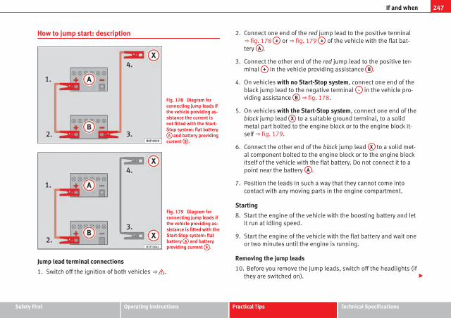
247If and when
How to jump start: description
Fig. 178 Diagram forconnecting jump leads ifthe vehicle providing as-sistance the current isnot fitted with the Start-Stop system: flat batteryA and battery providing
current B .
Fig. 179 Diagram forconnecting jump leads ifthe vehicle providing as-sistance is fitted with theStart-Stop system: flatbattery A and batteryproviding current B .
Jump lead terminal connections
1. Switch off the ignition of both vehicles ⇒ .
2. Connect one end of the red jump lead to the positive terminal⇒ fig. 178 + or ⇒ fig. 179 + of the vehicle with the flat bat-tery A .
3. Connect the other end of the red jump lead to the positive ter-minal + in the vehicle providing assistance B .
4. On vehicles with no Start-Stop system, connect one end of theblack jump lead to the negative terminal - in the vehicle pro-viding assistance B ⇒ fig. 178.
5. On vehicles with the Start-Stop system, connect one end of theblack jump lead X to a suitable ground terminal, to a solidmetal part bolted to the engine block or to the engine block it-self ⇒ fig. 179.
6. Connect the other end of the black jump lead X to a solid met-al component bolted to the engine block or to the engine blockitself of the vehicle with the flat battery. Do not connect it to apoint near the battery A .
7. Position the leads in such a way that they cannot come intocontact with any moving parts in the engine compartment.
Starting
8. Start the engine of the vehicle with the boosting battery and letit run at idling speed.
9. Start the engine of the vehicle with the flat battery and wait oneor two minutes until the engine is running.
Removing the jump leads
10. Before you remove the jump leads, switch off the headlights (ifthey are switched on).
Safety First Operating Instructions Practical Tips Technical Specifications

248 If and when
11. Turn on the heater blower and heated rear window in the vehi-cle with the flat battery. This helps minimise voltage peakswhich are generated when the leads are disconnected.
12. When the engine is running, disconnect the leads in reverseorder to the details given above.
Connect the battery clamps so they have good metal-to-metal contact withthe battery terminals.
If the engine fails to start, switch off the starter after about 10 seconds andtry again after about half a minute.
WARNING
● Please note the safety warnings referring to working in the enginecompartment ⇒ page 199, Working in the engine compartment.
● The battery providing assistance must have the same voltage as theflat battery (12V) and approximately the same capacity (see imprint onbattery). Failure to comply could result in an explosion.
● Never use jump leads when one of the batteries is frozen. Danger ofexplosion! Even after the battery has thawed, battery acid could leak andcause chemical burns. If a battery freezes, it should be replaced.
● Keep sparks, flames and lighted cigarettes away from batteries, dan-ger of explosion. Failure to comply could result in an explosion.
● Observe the instructions provided by the manufacturer of the jumpleads.
● Do not connect the negative cable from the other vehicle directly tothe negative terminal of the flat battery. The gas emitted from the batterycould be ignited by sparks. Danger of explosion.
● Do not attach the negative cable from the other vehicle to parts of thefuel system or to the brake line.
WARNING (Continued)
● The non-insulated parts of the battery clamps must not be allowed totouch. The jump lead attached to the positive battery terminal must nottouch metal parts of the vehicle, this can cause a short circuit.
● Position the leads in such a way that they cannot come into contactwith any moving parts in the engine compartment.
● Do not bend over the batteries. This could result in chemical burns.
NoteThe vehicles must not touch each other, otherwise electricity could flow assoon as the positive terminals are connected.

249If and when
Towing and tow-starting
Tow-starting*
The use of jump leads is preferable to tow-starting.
We recommend that you do not tow-start your vehicle. Jump-start-ing is preferable ⇒ page 246.
However, if your vehicle has to be tow-started:
– Engage the 2nd or the 3rd gear.
– Keep the clutch pressed down.
– Switch the ignition on.
– Once both vehicles are moving, release the clutch.
– As soon as the engine starts, press the clutch and move thegear lever into neutral. This helps to prevent driving into thetowing vehicle.
WARNING
The risk of accidents is high when tow-starting. The vehicle being towedcan easily collide with the towing vehicle.
CAUTIONWhen tow-starting, fuel could enter the catalytic converter and damage it.
Comments
Please observe the following points if you use a tow-rope:
Notes for the driver of the towing vehicle
– Drive slowly at first until the tow-rope is taut. Then accelerategradually.
– Begin and change gears cautiously. If you are driving an auto-matic vehicle, accelerate gently.
– Remember that the brake servo and power steering are notworking in the vehicle you are towing. Brake sooner than nor-mal and pressing the pedal gently.
Notes for the driver of the towed vehicle
– Ensure that the tow-rope remains taut at all times when towing.
Tow-rope or tow-bar
It is easier and safer to tow a vehicle with a tow-bar. You should only use atow-rope if you do not have a tow-bar.
A tow-rope should be slightly elastic to reduce the loading on both vehicles.It is advisable to use a tow-rope made of synthetic fibre or similarly elasticmaterial.
Attach the tow-rope or the tow-bar only to the towing eyes provided or atowing bracket.
Driving style
Towing requires some experience, especially when using a tow-rope. Bothdrivers should be familiar with the technique required for towing. Inexper-ienced drivers should not attempt to tow.
Safety First Operating Instructions Practical Tips Technical Specifications

250 If and when
Do not pull too hard with the towing vehicle and take care to avoid jerkingthe tow-rope. When towing on an unpaved road, there is always a risk ofoverloading and damaging the anchorage points.
The ignition of the vehicle being towed must be switched on to prevent thesteering wheel from locking and also to allow the use of the turn signals,horn, windscreen wipers and washers.
As the brake servo does not work if the engine is not running, you must ap-ply considerably more pressure to the brake pedal than you normally would.
As the power assisted steering does not work if the engine is not running,you will need more strength to steer than you normally would.
Towing vehicles with an automatic gearbox
● Put the selector lever into position “N”.
● Do not drive faster than 50 km/h.
● Do not tow further than 50 km.
● If a breakdown vehicle is used, the vehicle must be towed with the frontwheels raised.
Note● Observe legal requirements when towing or tow-starting.
● Switch on the hazard warning lights of both vehicles. However, observeany regulations to the contrary.
● For technical reasons, vehicles with an automatic gearbox must not betow-started.
● If damage to your vehicle means that there is no lubricant in the gear-box, you must raise the drive wheels while the vehicle is being towed.
● If the vehicle has to be towed more than 50 km, the front wheels shouldbe raised during towing, and towing should be carried out by a qualifiedperson.
● The steering wheel is locked when the vehicle has no electrical power.The vehicle must then be towed with the front wheels raised. Towing shouldbe carried out by a qualified person.
● The towing eye should always be kept in the vehicle.
Towing eyes
Fig. 180 Fitting the tow-ing eye to front rear ofthe vehicle
Fitting the towing eye
– Take the towing ring from the on-board tool set.
– Remove the front cover by pressing down on its left-hand side.For FR finishes, press down and pull outwards.
– Bolt the eye to its limit to the left, in the direction of the arrow⇒ fig. 180.

251If and when
Rear towing eye
Fig. 181 Rear towingring
There is a towing eye at the rear on the right below the rear bumper.
Safety First Operating Instructions Practical Tips Technical Specifications

252 Description of specifications
Technical Specifications
Description of specifications
Important information
Important
The information in the vehicle documentation always hasprecedence.
All technical specifications provided in this manual are valid for the stand-ard model in Spain. The vehicle data card included in the Maintenance Pro-gramme or the vehicle registration documents shows which engine is instal-led in the vehicle.
The figures may be different depending on if additional equipment is fitted,for different models, for special vehicles and for other countries.
Abbreviations used in the Technical Specifications section
Abbreviation Meaning
kW Kilowatt, engine power measurement.
PSPferdestärke (horsepower), formerly used to denote en-gine power.
rpm Revolutions per minute - engine speed.
Nm Newton metres, unit of engine torque.
l/100 km Fuel consumption in litres per 100 km.
g/km Carbon dioxide emissions in grams per km travelled.
CO2 Carbon dioxide
Abbreviation Meaning
CNCetane number, indication of the diesel combustion pow-er.
RONResearch octane number, indication of the knock resist-ance of petrol.

253Description of specifications
Vehicle identification data
The most important information is given on the identifica-tion plate and the vehicle data sticker.
Fig. 182 Vehicle datasticker (luggage compart-ment)
Vehicles for certain export countries do not have an identification plate.
Identification plate
The identification plate is located on the left rib inside the engine compart-ment.
Vehicle identification number
The vehicle identification number (chassis number) can be read from out-side the vehicle through a viewer in the windscreen. This is located on the
left-hand side of the vehicle in the lower area of the windscreen. It is alsolocated on the right hand side of the engine compartment.
Vehicle data
The data sticker is placed on the inside of the spare wheel well, in the lug-gage compartment and on the rear cover of the Maintenance Programme.
The following information is provided on the vehicle data sticker: ⇒ fig. 182
Production control number
Vehicle identification number (chassis number)
Model code number
Model designation / engine power output
Engine and gearbox code letters
Paintwork number / interior trim code
Optional equipment codes
Consumption values
CO2 emissions values
At the end of the data sticker, in points 8 and 9 , you can see the con-sumption and emission information.
Information on consumption and emissions1)
Urban consumption (l/100 km)
Urban CO2 emissions (g/km)
Extra-urban consumption (l/100 km)
Extra-urban CO2 emissions (g/km)
Combined consumption (l/100 km)
Combined CO2 emissions (g/km)
1
2
3
4
5
6
7
8
9
A
B
C
1) The values are not valid for certain countries. In such cases, the fields are marked with “X”.
Safety First Operating Instructions Practical Tips Technical Specifications

254 Description of specifications
Information on fuel consumption
Fuel consumption
The consumption and emission details shown on the vehicledata sticker differ from one vehicle to another.
The vehicle's fuel consumption and CO2 emissions can be consulted on thevehicle data sticker in the spare wheel well, inside the luggage compart-ment and on the rear cover of the Maintenance Programme.
The fuel consumption and CO2 emission values refer to the weight categoryassigned to your vehicle according to the engine and gearbox combination,as well as the specific equipment fitted, and is only used to compare be-tween the different models.
The fuel consumption and CO2 emissions do not depend only on the per-formance of the vehicle, they can also differ from the established values de-pending on other factors such as driving style, road conditions, traffic con-ditions, environmental conditions, load and number of passengers.
Calculation of fuel consumption
The consumption values have been calculated based on measurements per-formed or supervised by certified CE laboratories according to the latest ver-sion of directives 715/2007/EC and 80/1268/CEE (for more informationconsult the European Union Publications Office at EUR-Lex: © European Un-ion, http://eur-lex.europa.eu/en/index.htm) and are valid for the kerbweight indicated for the vehicle.
NoteIn practice, and considering all the factors mentioned here, consumptionvalues can differ from those calculated in the current European regulations.
Weights
Kerb weight refers to the basic model with a fuel tank filled to 90% capacityand without optional extras. The figure quoted includes 75 kg to allow forthe weight of the driver.
For special versions and optional equipment fittings or for the addition ofaccessories, the weight of the vehicle will increase ⇒ .
WARNING
● Please note that the centre of gravity may shift when transportingheavy objects; this may affect the vehicle's handling and lead to an acci-dent. Always adjust your speed and driving style to suit road conditionsand requirements.
● Never exceed the gross axle weight rating or the gross vehicle weightrating. If the allowed axle load or the allowed total weight is exceeded,the driving characteristics of the vehicle may change, leading to acci-dents, injuries and damage to the vehicle.
Towing a trailer
Trailer weights
Trailer weight
The trailer weights and drawbar loads approved are selected in intensive tri-als according to precisely defined criteria. The approved trailer weights arevalid for vehicles in the EU for maximum speeds of 80 km/h (in certain cir-cumstances up to 100 km/h). The figures may be different in other coun-tries. All data in the official vehicle documents take precedence over thesedata ⇒ .

255Description of specifications
Drawbar load
The maximum permitted drawbar load on the ball joint of the towing bracketmust not exceed 75 kg.
In the interest of road safety, we recommend that you always tow approach-ing the maximum drawbar load. The response of the trailer on the road willbe poor if the drawbar load is too small.
If the maximum permissible drawbar load cannot be met (e.g. with small,empty and light-weight single axle trailers or tandem axle trailers with awheelbase of less than 1 metre), a minimum of 4% of the actual trailerweight is legally required for the drawbar load.
WARNING
● For safety reasons, do not exceed the 80 km/h limit. This is also validin countries where higher speeds are permitted.
● Never exceed the maximum trailer weights or the drawbar load. If thepermissible axle load or the permissible total weight is exceeded, thedriving characteristics of the vehicle may change, leading to accidents,injuries and damage to the vehicle.
Wheels
Tyre pressure, snow chains, wheel bolts
Tyre pressures
The sticker with the tyre pressure values can be found on the inside of thetank flap. The tyre pressure values given there are for cold tyres. The slightlyraised pressures of warm tyres must not be reduced. ⇒
Snow chains
Snow chains may be fitted only to the front wheels, and only for the follow-ing tyres:
175/70R14185/60R15
Chains with links not exceeding 15 mm (including the chainclosure)
215/45R16 Chains with links not exceeding 9 mm (including the chainclosure)
215/40R17 Chains with links not exceeding 7 mm (including the chainclosure)
Wheel bolts
After the wheels have been changed, the tightening torque of the wheelbolts should be checked as soon as possible with a torque wrench ⇒ .The tightening torque for steel and alloy wheels is 120 Nm.
WARNING
● Check the tyre pressure at least once per month. Checking the tyrepressure is very important. If the tyre pressure is too high or too low,there is an increased danger of accidents, particularly at high speeds.
● If the torque of the wheel bolts is too low, they could loosen while thevehicle is in motion. Risk of accident! If the tightening torque is too high,the wheel bolts and threads can be damaged.
NoteWe recommend that you ask your Authorised Service Centre for informationabout appropriate wheel, tyre and snow chain size.
Safety First Operating Instructions Practical Tips Technical Specifications
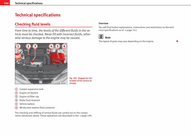
256 Technical specifications
Technical specifications
Checking fluid levels
From time to time, the levels of the different fluids in the ve-hicle must be checked. Never fill with incorrect fluids, other-wise serious damage to the engine may be caused.
Fig. 183 Diagram for thelocation of the various el-ements
Coolant expansion tank
Engine oil dipstick
Engine oil filler cap
Brake fluid reservoir
Vehicle battery
Windscreen washer fluid container
The checking and refilling of service fluids are carried out on the compo-nents mentioned above. These operations are described in the ⇒ page 199.
1
2
3
4
5
6
Overview
You will find further explanations, instructions and restrictions on the tech-nical specifications as of ⇒ page 252.
NoteThe layout of parts may vary depending on the engine.

257Technical specifications
Petrol engine 1.2 51 kW (70 PS)
Engine specifications
Power output in kW (PS) rpm 51 (70)/ 5400
Maximum torque in Nm at rpm 112/ 3000
No. of cylinders/capacity in cm3 3/ 1198
Fuel Super 95 RONa)/Normal 91 RONb)
a) Research Octane Number = Anti-detonation rating of the petrol.b) Slight power loss.
Performance
Maximum speed in km/h 163
Acceleration from 0-80 km/h in sec. 9,4
Acceleration from 0-100 km/h in sec. 14,6
Weights
Gross vehicle weight in kg 1565
Weight in running order (with driver) in kg 1110
Gross front axle weight in kg 830
Gross rear axle weight in kg 820
Permitted roof load in kg 75
Trailer weight
Trailer without brakes 550
Trailer with brakes, gradients up to 8% 1000
Trailer with brakes, gradients up to 12% 800
Engine oil capacity
Approximate engine oil capacity with oil filter change 2.75 litres
Safety First Operating Instructions Practical Tips Technical Specifications

258 Technical specifications
Petrol engine 1.4 63 kW (85 PS)
Engine specifications
Power output in kW (PS) rpm 63 (85)/ 5000
Maximum torque in Nm at rpm 132/ 3800
No. of cylinders/capacity in cm3 4/ 1390
Fuel Super 95 RONa)/Normal 91 RONb)
a) Research Octane Number = Anti-detonation rating of the petrol.b) Slight power loss.
Performance
Maximum speed in km/h 177
Acceleration from 0-80 km/h in sec. 8
Acceleration from 0-100 km/h in sec. 12,4
Weights
Gross vehicle weight in kg 1585
Weight in running order (with driver) in kg 1130
Gross front axle weight in kg 860
Gross rear axle weight in kg 820
Permitted roof load in kg 75
Trailer weight
Trailer without brakes 560
Trailer with brakes, gradients up to 8% 1200
Trailer with brakes, gradients up to 12% 1000
Engine oil capacity
Approximate engine oil capacity with oil filter change 2.8 litres

259Technical specifications
Petrol engine 1.2 TSI 77 kW (105 PS)
Engine specifications
Power output in kW (PS) rpm 77 (105)/5000
Maximum torque in Nm at rpm 175/1550-4100
No. of cylinders/capacity in cm3 4/ 1197
Fuel Super 95 RONa)/Normal 91 RONb)
a) Research Octane Number = Anti-detonation rating of the petrol.b) With a slight power loss
Performance
Manual Automatic
Maximum speed in km/h 190 190
Acceleration from 0-80 km/h in sec. 6,8 6,7
Acceleration from 0-100 km/h in sec. 10,2 10
Weights
Manual Automatic
Gross vehicle weight in kg 1600 1620
Weight in running order (with driver) in kg 1145 1165
Gross front axle weight in kg 860 890
Gross rear axle weight in kg 820 820
Permitted roof load in kg 75 75
Trailer weight
Manual Automatic
Trailer without brakes 570 580
Trailer with brakes, gradients up to 8% 1200 1200
Trailer with brakes, gradients up to 12% 1200 1200
Safety First Operating Instructions Practical Tips Technical Specifications

260 Technical specifications
Engine oil capacity
Approximate engine oil capacity with oil filter change 3.6 litres
Petrol engine 1.2 TSI 77 kW (105 PS) Start-Stop
Engine specifications
Power output in kW (PS) rpm 77 (105)/ 5000
Maximum torque in Nm at rpm 175/1550-4100
No. of cylinders/capacity in cm3 4/ 1197
Fuel Super 95 RONa)/Normal 91 RONb)
a) Research Octane Number = Anti-detonation rating of the petrol.b) Slight power loss.
Performance
Maximum speed in km/h 190
Acceleration from 0-80 km/h in sec. 6,8
Acceleration from 0-100 km/h in sec. 10,2
Weights
Gross vehicle weight in kg 1605
Weight in running order (with driver) in kg 1150
Gross front axle weight in kg 860
Gross rear axle weight in kg 820
Permitted roof load in kg 75
Trailer weight
Trailer without brakes 570
Trailer with brakes, gradients up to 8% 1200
Trailer with brakes, gradients up to 12% 1200

261Technical specifications
Engine oil capacity
Approximate engine oil capacity with oil filter change 3.6 litres
Petrol engine 1.4 TSI 110 kW (150 PS) Automatic
Engine specifications
Power output in kW (PS) rpm 110 (150)/ 5800
Maximum torque in Nm at rpm 220/ 1250-4500
No. of cylinders/capacity in cm3 4/ 1390
Fuel Super 95 RONa)/Normal 91 RONb)
a) Research Octane Number = Anti-detonation rating of the petrol.b) Slight power loss.
Performance
Maximum speed in km/h 212
Acceleration from 0-80 km/h in sec. 5,7
Acceleration from 0-100 km/h in sec. 6
Weights
Gross vehicle weight in kg 1735
Weight in running order (with driver) in kg 1280
Gross front axle weight in kg 950
Gross rear axle weight in kg 820
Permitted roof load in kg 75
Trailer weight
Trailer without brakes 640
Trailer with brakes, gradients up to 8% 1300
Trailer with brakes, gradients up to 12% 1200
Safety First Operating Instructions Practical Tips Technical Specifications
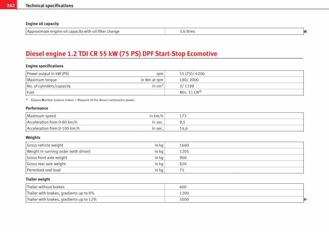
262 Technical specifications
Engine oil capacity
Approximate engine oil capacity with oil filter change 3.6 litres
Diesel engine 1.2 TDI CR 55 kW (75 PS) DPF Start-Stop Ecomotive
Engine specifications
Power output in kW (PS) rpm 55 (75)/ 4200
Maximum torque in Nm at rpm 180/ 2000
No. of cylinders/capacity in cm3 3/ 1199
Fuel Min. 51 CNa)
a) Cetane Number (cetane index) = Measure of the diesel combustion power.
Performance
Maximum speed in km/h 173
Acceleration from 0-80 km/h in sec. 9,5
Acceleration from 0-100 km/h in sec. 14,6
Weights
Gross vehicle weight in kg 1660
Weight in running order (with driver) in kg 1205
Gross front axle weight in kg 900
Gross rear axle weight in kg 820
Permitted roof load in kg 75
Trailer weight
Trailer without brakes 600
Trailer with brakes, gradients up to 8% 1200
Trailer with brakes, gradients up to 12% 1000

263Technical specifications
Engine oil capacity
Approximate engine oil capacity with oil filter change 4.1 litres
Diesel engine 1.2 TDI CR 55 kW (75 PS) DPF
Engine specifications
Power output in kW (PS) rpm 55 (75)/ 4200
Maximum torque in Nm at rpm 180/ 2000
No. of cylinders/capacity in cm3 3/ 1199
Fuel Min. 51 CNa)
a) Cetane Number (cetane index) = Measure of the diesel combustion power.
Performance
Maximum speed in km/h 168
Acceleration from 0-80 km/h in sec. 9,5
Acceleration from 0-100 km/h in sec. 14,5
Weights
Gross vehicle weight in kg 1645
Weight in running order (with driver) in kg 1190
Gross front axle weight in kg 900
Gross rear axle weight in kg 820
Permitted roof load in kg 75
Trailer weight
Trailer without brakes 590
Trailer with brakes, gradients up to 8% 1200
Trailer with brakes, gradients up to 12% 1000
Safety First Operating Instructions Practical Tips Technical Specifications
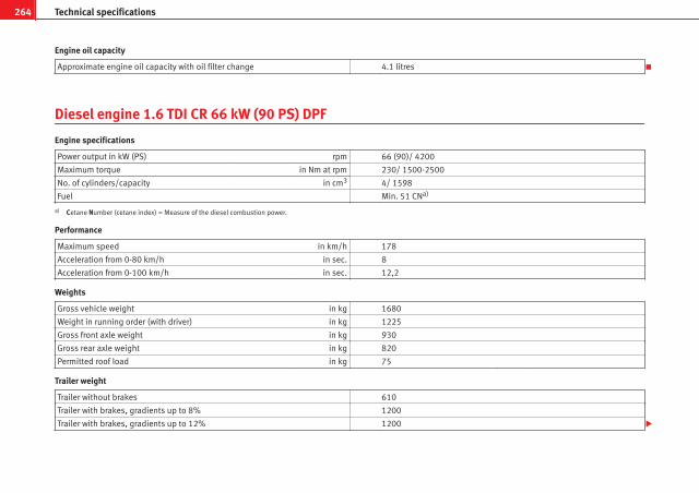
264 Technical specifications
Engine oil capacity
Approximate engine oil capacity with oil filter change 4.1 litres
Diesel engine 1.6 TDI CR 66 kW (90 PS) DPF
Engine specifications
Power output in kW (PS) rpm 66 (90)/ 4200
Maximum torque in Nm at rpm 230/ 1500-2500
No. of cylinders/capacity in cm3 4/ 1598
Fuel Min. 51 CNa)
a) Cetane Number (cetane index) = Measure of the diesel combustion power.
Performance
Maximum speed in km/h 178
Acceleration from 0-80 km/h in sec. 8
Acceleration from 0-100 km/h in sec. 12,2
Weights
Gross vehicle weight in kg 1680
Weight in running order (with driver) in kg 1225
Gross front axle weight in kg 930
Gross rear axle weight in kg 820
Permitted roof load in kg 75
Trailer weight
Trailer without brakes 610
Trailer with brakes, gradients up to 8% 1200
Trailer with brakes, gradients up to 12% 1200

265Technical specifications
Engine oil capacity
Approximate engine oil capacity with oil filter change 4.3 litres
Diesel engine 1.6 TDI CR 77 kW (105 PS) with/without DPF
Engine specifications
Power output in kW (PS) rpm 77 (105)/ 4400
Maximum torque in Nm at rpm 250/ 1500-2500
No. of cylinders/capacity in cm3 4/ 1598
Fuel Min. 51 CNa)
a) Cetane Number (cetane index) = Measure of the diesel combustion power.
Performance
Maximum speed in km/h 188
Acceleration from 0-80 km/h in sec. 7,3
Acceleration from 0-100 km/h in sec. 10,9
Weights
Gross vehicle weight in kg 1680
Weight in running order (with driver) in kg 1225
Gross front axle weight in kg 930
Gross rear axle weight in kg 820
Permitted roof load in kg 75
Trailer weight
Trailer without brakes 610
Trailer with brakes, gradients up to 8% 1200
Trailer with brakes, gradients up to 12% 1200
Safety First Operating Instructions Practical Tips Technical Specifications

266 Technical specifications
Engine oil capacity
Approximate engine oil capacity with oil filter change 4.3 litres

267Technical specifications
Dimensions and capacities
Dimensions
Length, width 4236 mm/ 1693 mm
Height at kerb weight (with bars) 1445 mm
Front and rear projection 857 mm/ 910 mm
Wheelbase 2469 mm
Turning circle 10.7 m
Track widtha) Front Rear
1465 mm 1457 mm
Capacities
Fuel tank 45 l. Reserve 7 l.
Windscreen washer fluid container with headlight washer 2 l/4.5 l
Tyre pressure
Summer-grade tyres:
The correct tyre pressure can be seen on the sticker on the inside of the tank flap.
Winter tyres:
The pressure of these tyres is the same as the summer tyre pressure plus 0.2 bar.
a) This data will change depending on the type of wheel rim.
Safety First Operating Instructions Practical Tips Technical Specifications


Index
AABS . . . . . . . . . . . . . . . . . . . . . . . . . . . . . . . . . . 168
Warning lamp . . . . . . . . . . . . . . . . . . . . . . . . 69
Accessories . . . . . . . . . . . . . . . . . . . . . . . . . . . . 189
Acoustic signal . . . . . . . . . . . . . . . . . . . . . . . . . . 20
Acoustic warning . . . . . . . . . . . . . . . . . . . . . . . 143
Adaptive headlights . . . . . . . . . . . . . . . . . . . . . 100
AFS headlight bulbs . . . . . . . . . . . . . . . . . . . . . 240
Airbag covers . . . . . . . . . . . . . . . . . . . . . . . . . . . 36
Airbag system . . . . . . . . . . . . . . . . . . . . . . . . . . . 30Front airbags . . . . . . . . . . . . . . . . . . . . . . . . 34side airbags . . . . . . . . . . . . . . . . . . . . . . . . . 38Warning lamp . . . . . . . . . . . . . . . . . . . . . . . . 31
Air conditionerClimatronic . . . . . . . . . . . . . . . . . . . . . . . . . 138General notes . . . . . . . . . . . . . . . . . . . . . . . 140
Air conditioning* . . . . . . . . . . . . . . . . . . . . . . . 135
Air outlets . . . . . . . . . . . . . . . . . . . . . . . . . . . . . 134
Air recirculationSemi-automatic air conditioning . . . . . . . . 137
Air recirculation modeClimatronic . . . . . . . . . . . . . . . . . . . . . . . . . 140
Alarm systemSwitching off . . . . . . . . . . . . . . . . . . . . . . . . . 87
AlternatorWarning lamp . . . . . . . . . . . . . . . . . . . . . . . . 74
Anti-freeze . . . . . . . . . . . . . . . . . . . . . . . . . . . . 206
Anti-lock brake system . . . . . . . . . . . . . . . . . . . 168Warning lamp . . . . . . . . . . . . . . . . . . . . . . . . 69
Anti-theft alarm system . . . . . . . . . . . . . . . . . . . 87Switching off . . . . . . . . . . . . . . . . . . . . . . . . . 87
Anti-theft wheel bolts . . . . . . . . . . . . . . . . . . . 224
Aquaplaning . . . . . . . . . . . . . . . . . . . . . . . . . . . 217
Ashtray . . . . . . . . . . . . . . . . . . . . . . . . . . . . . . . 123
Aspects to note before setting off . . . . . . . . . . . . 8
Automatic anti-dazzle interior mirrorDeactivating the anti-dazzle function . . . . 110
Automatic anti-dazzle interior mirror*Activating the anti-dazzle function . . . . . . 110
Automatic car washing tunnel . . . . . . . . . . . . . 181
Automatic gearbox . . . . . . . . . . . . . . . . . . . . . . 152Kick-down feature . . . . . . . . . . . . . . . . . . . . 159Selector lever positions . . . . . . . . . . . . . . . 157
Automatic lighting . . . . . . . . . . . . . . . . . . . . . . . 98
Automatic windscreeen wiper/washer . . . . . . 106
AUX/USB input connection . . . . . . . . . . . . . . . 126
Auxiliary audio input connection (AUX) . . . . . 125
BBall coupling . . . . . . . . . . . . . . . . . . . . . . . . . . . 179
BatteryChanging . . . . . . . . . . . . . . . . . . . . . . . . . . 214Charging . . . . . . . . . . . . . . . . . . . . . . . . . . . 214Winter conditions . . . . . . . . . . . . . . . . . . . . 213
Before setting off . . . . . . . . . . . . . . . . . . . . . . . . . 8
Belt tensioners . . . . . . . . . . . . . . . . . . . . . . . . . . 28
Biodiesel . . . . . . . . . . . . . . . . . . . . . . . . . . . . . . 198
Biodiesel fuel . . . . . . . . . . . . . . . . . . . . . . . . . . 198
Bonnet . . . . . . . . . . . . . . . . . . . . . . . . . . . . . . . 201
Brake fluid . . . . . . . . . . . . . . . . . . . . . . . . . . . . 211Changing . . . . . . . . . . . . . . . . . . . . . . . . . . 212
Brake pads . . . . . . . . . . . . . . . . . . . . . . . . . . . . 172
Brakes . . . . . . . . . . . . . . . . . . . . . . . . . . . . . . . . 172
Brake servo . . . . . . . . . . . . . . . . . . . . . . . . 167, 172
Brake system . . . . . . . . . . . . . . . . . . . . . . . . . . 211Warning lamp . . . . . . . . . . . . . . . . . . . . . . . . 71
Braking distance . . . . . . . . . . . . . . . . . . . . . . . 172
Bulb changedouble headlight . . . . . . . . . . . . . . . . . . . . 236Single headlight bulb . . . . . . . . . . . . . . . . 234
Bulb changesGeneral notes . . . . . . . . . . . . . . . . . . . . . . . 232
Bulb defectWarning lamp . . . . . . . . . . . . . . . . . . . . . . . . 69
Buzzer . . . . . . . . . . . . . . . . . . . . . . . . . . . . 104, 143
CCar care
Exterior . . . . . . . . . . . . . . . . . . . . . . . . . . . . 181
Car phone . . . . . . . . . . . . . . . . . . . . . . . . . . . . . 190
Catalytic converter . . . . . . . . . . . . . . . . . . . . . . 173
CCS . . . . . . . . . . . . . . . . . . . . . . . . . . . . . . . . . . 163
269Index

Central locking . . . . . . . . . . . . . . . . . . . . . . . . . . 79Automatic speed dependent locking and
unlocking system* . . . . . . . . . . . . . . . . . . 81Emergency unlocking system . . . . . . . . . . . 82Locking system for involuntary unlocking . 81Selective unlocking system* . . . . . . . . . . . . 80Unlocking system* . . . . . . . . . . . . . . . . . . . . 81
Central locking buttonLocking . . . . . . . . . . . . . . . . . . . . . . . . . . . . . 82Unlocking . . . . . . . . . . . . . . . . . . . . . . . . . . . 82
Cetane number . . . . . . . . . . . . . . . . . . . . . . . . . 198
Changing bulbsinterior light and front reading lights . . . . 245
Changing gearsee Manual gearbox . . . . . . . . . . . . . . . . . . 151
Changing gear in tiptronic mode . . . . . . . . . . 156
Changing rear lightson the tailgate . . . . . . . . . . . . . . . . . . . . . . 243on the wing . . . . . . . . . . . . . . . . . . . . . . . . . 242
Changing single headlight bulbsTurn signal bulb . . . . . . . . . . . . . . . . . . . . . 234
Changing the AFS headlight bulbsXenon lights . . . . . . . . . . . . . . . . . . . . . . . . 240
Changing the bulbsAFS headlight bulbs . . . . . . . . . . . . . . . . . . 240fog light bulbs . . . . . . . . . . . . . . . . . . . . . . 241Luggage compartment light . . . . . . . . . . . 246number plate light . . . . . . . . . . . . . . . . . . . 244Side turn signal lights . . . . . . . . . . . . . . . . 244
Changing the main headlight bulbturn signal lights . . . . . . . . . . . . . . . . . . . . 238
Changing the main headlight bulbsturn signal lights . . . . . . . . . . . . . . . . . . . . 240
Changing the single headlight bulbsDipped/main beam . . . . . . . . . . . . . . . . . . 235Side light . . . . . . . . . . . . . . . . . . . . . . . . . . 235
Changing windscreen wiper blades . . . . . . . . 209
Chassis number . . . . . . . . . . . . . . . . . . . . . . . . 253
Checking . . . . . . . . . . . . . . . . . . . . . . . . . . . . . . 214
Checking battery electrolyte level . . . . . . . . . . 214
Checking engine oil level . . . . . . . . . . . . . . . . . 203
Child safety . . . . . . . . . . . . . . . . . . . . . . . . . . . . . 43
Child seat . . . . . . . . . . . . . . . . . . . . . . . . . . . . . . 45Categorisation in groups . . . . . . . . . . . . . . . 45Group 1 . . . . . . . . . . . . . . . . . . . . . . . . . . . . . 46Group 2 . . . . . . . . . . . . . . . . . . . . . . . . . . . . . 46Group 3 . . . . . . . . . . . . . . . . . . . . . . . . . . . . . 46Groups 0 and 0+ . . . . . . . . . . . . . . . . . . . . . . 45ISOFIX system . . . . . . . . . . . . . . . . . . . . . . . . 48Safety notes . . . . . . . . . . . . . . . . . . . . . . . . . 43Securing . . . . . . . . . . . . . . . . . . . . . . . . . . . . 48
Child seatson the front passenger seat . . . . . . . . . . . . . 31Top Tether system . . . . . . . . . . . . . . . . . . . . 49
Cigarette lighter . . . . . . . . . . . . . . . . . . . . . . . . 124
Cleaning alloy wheel rims . . . . . . . . . . . . . . . . 185
Cleaning chrome . . . . . . . . . . . . . . . . . . . . . . . 184
Cleaning engine compartment . . . . . . . . . . . . 186
Cleaning steel wheel rims . . . . . . . . . . . . . . . . 185
Cleaning windows . . . . . . . . . . . . . . . . . . . . . . 183
Climatronicautomatic mode . . . . . . . . . . . . . . . . . . . . . 139controls . . . . . . . . . . . . . . . . . . . . . . . . . . . . 138General notes . . . . . . . . . . . . . . . . . . . . . . . 140manual mode . . . . . . . . . . . . . . . . . . . . . . . 139
Clock . . . . . . . . . . . . . . . . . . . . . . . . . . . . . . . . . . 58
Cloth seat covers cleaning . . . . . . . . . . . . . . . . 187
Cockpit . . . . . . . . . . . . . . . . . . . . . . . . . . . . . . . . 53
Coming Home function . . . . . . . . . . . . . . . . . . 100
Compartment for on-board documentation . . 120
ControlExterior mirrors . . . . . . . . . . . . . . . . . . . . . . 111
Control lamps . . . . . . . . . . . . . . . . . . . . . . . . . . . 63
Control lighting . . . . . . . . . . . . . . . . . . . . . . . . . . 53
ControlsElectric windows . . . . . . . . . . . . . . . . . . . . . . 92
Convenience closingSliding/tilting sunroof . . . . . . . . . . . . . . . . . 96Windows . . . . . . . . . . . . . . . . . . . . . . . . . . . . 94
Convenience openingWindows . . . . . . . . . . . . . . . . . . . . . . . . . . . . 94
Coolant . . . . . . . . . . . . . . . . . . . . . . . . . . . . . . . 206
Coolant level . . . . . . . . . . . . . . . . . . . . . . . . . . . 206Warning lamp . . . . . . . . . . . . . . . . . . . . . . . . 73
Coolant loss . . . . . . . . . . . . . . . . . . . . . . . . . . . 206
Coolant temperatureSafety instructions . . . . . . . . . . . . . . . . . . . . 74Warning lamp . . . . . . . . . . . . . . . . . . . . . . . . 73
Correct adjustment of front head restraints . . . 13
Correct sitting positionFront passenger . . . . . . . . . . . . . . . . . . . . . . 12Incorrect sitting position . . . . . . . . . . . . . . . 14
Cruise controlControl lamp . . . . . . . . . . . . . . . . . . . . . . . . . 71
Cruise control system . . . . . . . . . . . . . . . . . . . . 163
Cruise speed . . . . . . . . . . . . . . . . . . . . . . . . . . . 163Control lamp . . . . . . . . . . . . . . . . . . . . . . . . . 71
270 Index
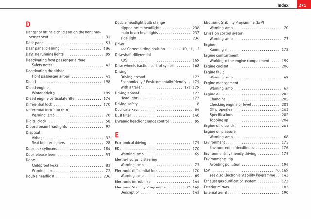
DDanger of fitting a child seat on the front pas-
senger seat . . . . . . . . . . . . . . . . . . . . . . . . . . . 31
Dash panel . . . . . . . . . . . . . . . . . . . . . . . . . . . . . 53
Dash panel cleaning . . . . . . . . . . . . . . . . . . . . 186
Daytime running lights . . . . . . . . . . . . . . . . . . . 99
Deactivating front passenger airbagSafety notes . . . . . . . . . . . . . . . . . . . . . . . . . 42
Deactivating the airbagFront passenger airbag . . . . . . . . . . . . . . . . 41
Diesel . . . . . . . . . . . . . . . . . . . . . . . . . . . . . . . . 198
Diesel engineWinter driving . . . . . . . . . . . . . . . . . . . . . . . 199
Diesel engine particulate filter . . . . . . . . . . . . 174
Differential lock . . . . . . . . . . . . . . . . . . . . . . . . 170
Differential lock fault (EDL)Warning lamp . . . . . . . . . . . . . . . . . . . . . . . . 70
Digital clock . . . . . . . . . . . . . . . . . . . . . . . . . . . . 58
Dipped beam headlights . . . . . . . . . . . . . . . . . . 97
DisposalAirbags . . . . . . . . . . . . . . . . . . . . . . . . . . . . . 32Seat belt tensioners . . . . . . . . . . . . . . . . . . . 28
Door lock cylinders . . . . . . . . . . . . . . . . . . . . . . 184
Door release lever . . . . . . . . . . . . . . . . . . . . . . . 53
DoorsChildproof locks . . . . . . . . . . . . . . . . . . . . . . 83Warning lamp . . . . . . . . . . . . . . . . . . . . . . . . 72
Double headlight . . . . . . . . . . . . . . . . . . . . . . . 236
Double headlight bulb changedipped beam headlights . . . . . . . . . . . . . . 238main beam headlights . . . . . . . . . . . . . . . . 237side light . . . . . . . . . . . . . . . . . . . . . . . . . . . 236
Driversee Correct sitting position . . . . . . . 10, 11, 12
Driveshaft differentialXDS . . . . . . . . . . . . . . . . . . . . . . . . . . . . . . . 169
Drive wheels traction control system . . . . . . . 168
DrivingDriving abroad . . . . . . . . . . . . . . . . . . . . . . 177Economically / Environmentally friendly . 175With a trailer . . . . . . . . . . . . . . . . . . . . 178, 179
Driving abroad . . . . . . . . . . . . . . . . . . . . . . . . . 177Headlights . . . . . . . . . . . . . . . . . . . . . . . . . 177
Driving safety . . . . . . . . . . . . . . . . . . . . . . . . . . . . 8
Duplicate keys . . . . . . . . . . . . . . . . . . . . . . . . . . 84
Dust filter . . . . . . . . . . . . . . . . . . . . . . . . . . . . . 140
Dynamic headlight range control . . . . . . . . . . . 99
EEconomical driving . . . . . . . . . . . . . . . . . . . . . . 175
EDL . . . . . . . . . . . . . . . . . . . . . . . . . . . . . . . . . . 170Warning lamp . . . . . . . . . . . . . . . . . . . . . . . . 69
Electro-hydraulic steeringWarning lamp . . . . . . . . . . . . . . . . . . . . . . . . 73
Electronic differential lock . . . . . . . . . . . . . . . . 170Warning lamp . . . . . . . . . . . . . . . . . . . . . . . . 69
Electronic immobiliser . . . . . . . . . . . . . . . . . . . 144
Electronic Stability Programme . . . . . . . . . 70, 169Description . . . . . . . . . . . . . . . . . . . . . . . . . 143
Electronic Stability Programme (ESP)Warning lamp . . . . . . . . . . . . . . . . . . . . . . . . 70
Emission control systemWarning lamp . . . . . . . . . . . . . . . . . . . . . . . . 73
EngineRunning in . . . . . . . . . . . . . . . . . . . . . . . . . 172
Engine compartmentWorking in the engine compartment . . . . 199
Engine coolant . . . . . . . . . . . . . . . . . . . . . . . . . 206
Engine faultWarning lamp . . . . . . . . . . . . . . . . . . . . . . . . 68
Engine managementWarning lamp . . . . . . . . . . . . . . . . . . . . . . . . 67
Engine oil . . . . . . . . . . . . . . . . . . . . . . . . . . . . . 202Changing . . . . . . . . . . . . . . . . . . . . . . . . . . 205Checking engine oil level . . . . . . . . . . . . . . 203Oil properties . . . . . . . . . . . . . . . . . . . . . . . 203Specifications . . . . . . . . . . . . . . . . . . . . . . . 202Topping up . . . . . . . . . . . . . . . . . . . . . . . . . 204
Engine oil dipstick . . . . . . . . . . . . . . . . . . . . . . 203
Engine oil pressureWarning lamp . . . . . . . . . . . . . . . . . . . . . . . . 68
Environment . . . . . . . . . . . . . . . . . . . . . . . . . . . 175Environmental friendliness . . . . . . . . . . . . 176
Environmentally friendly driving . . . . . . . . . . . 175
Environmental tipAvoiding pollution . . . . . . . . . . . . . . . . . . . 194
ESP . . . . . . . . . . . . . . . . . . . . . . . . . . . . . . . 70, 169see also Electronic Stability Programme . . 143
Exhaust gas purification system . . . . . . . . . . . 173
Exterior mirrors . . . . . . . . . . . . . . . . . . . . . . . . . 183
External aerial . . . . . . . . . . . . . . . . . . . . . . . . . . 190
271Index

FFabric trim cleaning . . . . . . . . . . . . . . . . . . . . . 187
Fastening rings . . . . . . . . . . . . . . . . . . . . . . . . . . 17
Fire extinguisher . . . . . . . . . . . . . . . . . . . . . . . . 127
First-aid kit . . . . . . . . . . . . . . . . . . . . . . . . . . . . 127
Floor mats . . . . . . . . . . . . . . . . . . . . . . . . . . . . . . 16
Fog lights . . . . . . . . . . . . . . . . . . . . . . . . . . . . . . 97
Fog lights bulb . . . . . . . . . . . . . . . . . . . . . . . . . 241
Fog lights with cornering function . . . . . . . . . 100
Front airbags . . . . . . . . . . . . . . . . . . . . . . . . . . . 34Description . . . . . . . . . . . . . . . . . . . . . . . . . . 34Operation . . . . . . . . . . . . . . . . . . . . . . . . . . . 35Safety notes . . . . . . . . . . . . . . . . . . . . . . . . . 37
Front drink holder . . . . . . . . . . . . . . . . . . . . . . . 122
Front interior light . . . . . . . . . . . . . . . . . . . . . . 104
Front passenger airbag deactivation . . . . . . . . 41
Front reading light . . . . . . . . . . . . . . . . . . . . . . 105
Front seat adjustmentLumbar support . . . . . . . . . . . . . . . . . . . . . 116
FuelDiesel . . . . . . . . . . . . . . . . . . . . . . . . . . . . . 198Petrol . . . . . . . . . . . . . . . . . . . . . . . . . . . . . . 198
Fuel consumption . . . . . . . . . . . . . . . . . . . . . . . 253
Fuel levelIndicator . . . . . . . . . . . . . . . . . . . . . . . . . . . . 57
Fuel reserveWarning lamp . . . . . . . . . . . . . . . . . . . . . . . . 72
Fuel tanksee Fuel reserve . . . . . . . . . . . . . . . . . . . . . . 72
Fuel TankOpening the fuel tank flap . . . . . . . . . . . . . 193
Fuel: save . . . . . . . . . . . . . . . . . . . . . . . . . . . . . 175
Fuses . . . . . . . . . . . . . . . . . . . . . . . . . . . . . . . . . 229
GG 12 . . . . . . . . . . . . . . . . . . . . . . . . . . . . . . . . . . 206
Gear shift pattern . . . . . . . . . . . . . . . . . . . . . . . 151
General overview of the engine compartment 256
Glove compartment . . . . . . . . . . . . . . . . . . . . . 120
Glove compartment light . . . . . . . . . . . . . . . . . 105
Glow plug system . . . . . . . . . . . . . . . . . . . . . . . 146Warning lamp . . . . . . . . . . . . . . . . . . . . . . . . 68
HHandbrake . . . . . . . . . . . . . . . . . . . . . . . . . . . . 159
Warning lamp . . . . . . . . . . . . . . . . . . . . . . . 160
Hazard warning lights . . . . . . . . . . . . . . . . . . . 102
HBA . . . . . . . . . . . . . . . . . . . . . . . . . . . . . . . . . . 167
Headlight flashers . . . . . . . . . . . . . . . . . . . . . . 103
Headlight range control . . . . . . . . . . . . . . . . . . . 99
HeadlightsDriving abroad . . . . . . . . . . . . . . . . . . . . . . 177Fog lights . . . . . . . . . . . . . . . . . . . . . . . . . . . 97Headlight washer . . . . . . . . . . . . . . . . . . . . 109
Head restraintsAdjusting . . . . . . . . . . . . . . . . . . . . . . 114, 115Adjustment of the head restraint angle . . 115Removing . . . . . . . . . . . . . . . . . . . . . . . . . . 115
Heated exterior mirrors* . . . . . . . . . . . . . . . . . 111
Heated front seats . . . . . . . . . . . . . . . . . . . . . . 117
Heating . . . . . . . . . . . . . . . . . . . . . . . . . . . . . . . 132
Heating system . . . . . . . . . . . . . . . . . . . . . . . . . 133
High pressure cleaners . . . . . . . . . . . . . . . . . . 182
Hill-start assist . . . . . . . . . . . . . . . . . . . . . . . . . 161
Horn . . . . . . . . . . . . . . . . . . . . . . . . . . . . . . . . . . 53
How to jump start description . . . . . . . . . . . . . 247
Hydraulic Brake AssistAutomatic hazard warning lights activa-
tion . . . . . . . . . . . . . . . . . . . . . . . . . . . . . . 167
IIdentification number . . . . . . . . . . . . . . . . . . . 253
Identification plate . . . . . . . . . . . . . . . . . . . . . . 253
Ignition key . . . . . . . . . . . . . . . . . . . . . . . . . . . . 143
Ignition lock . . . . . . . . . . . . . . . . . . . . . . . . . . . 143
Information in the multifunction displayMemory displays . . . . . . . . . . . . . . . . . . . . . 59
Instrument and switch lighting . . . . . . . . . . . . . 99
Instrument lighting . . . . . . . . . . . . . . . . . . . . . . 53
Instrument panelService interval display . . . . . . . . . . . . . . . . 61
Instruments . . . . . . . . . . . . . . . . . . . . . . . . . . . . 55
Interior mirror . . . . . . . . . . . . . . . . . . . . . . . . . . 109
Interior monitoring and anti-towing alarm*Activation . . . . . . . . . . . . . . . . . . . . . . . . . . . 88
Intermittent wipe, windscreen . . . . . . . . . . . . . 106
ISOFIX system . . . . . . . . . . . . . . . . . . . . . . . . . . . 48
JJump-starting . . . . . . . . . . . . . . . . . . . . . . . . . . 246
Jump leads . . . . . . . . . . . . . . . . . . . . . . . . . . . . 246
272 Index

KKeys . . . . . . . . . . . . . . . . . . . . . . . . . . . . . . . . . . . 84
LLeather cleaning . . . . . . . . . . . . . . . . . . . . . . . . 187
Leaving Home function . . . . . . . . . . . . . . . . . . 100
Lights . . . . . . . . . . . . . . . . . . . . . . . . . . . . . . . . . 97
Load compartment in the luggage compart-ment
see Loading the luggage compartment . . . 16
Loading the luggage compartment . . . . . . . . . . 16
Locks . . . . . . . . . . . . . . . . . . . . . . . . . . . . . . . . . 184
LPG . . . . . . . . . . . . . . . . . . . . . . . . . . 56, 147, 195
LPG systemDriving . . . . . . . . . . . . . . . . . . . . . . . . . . . . . 147Filler neck adapter . . . . . . . . . . . . . . . . . . . 196Level indicator . . . . . . . . . . . . . . . . . . . . . . . 56Refuelling . . . . . . . . . . . . . . . . . . . . . . . . . . 195
Luggage compartment . . . . . . . . . . . . . . . . . . . 127Fastening rings . . . . . . . . . . . . . . . . . . . . . . 128Loading . . . . . . . . . . . . . . . . . . . . . . . . . . . . 127Luggage net . . . . . . . . . . . . . . . . . . . . . . . . 129see also Loading the luggage compartment . .16
Luggage compartment light* . . . . . . . . . . . . . 105
MMain beam . . . . . . . . . . . . . . . . . . . . . . . . . 97, 103
Main beam headlightsIndicator lamp . . . . . . . . . . . . . . . . . . . . . . . 73
MaintenanceAirbags . . . . . . . . . . . . . . . . . . . . . . . . . . . . . 32
Maintenance and cleaning . . . . . . . . . . . . . . . 180
Manual gearbox . . . . . . . . . . . . . . . . . . . . . . . . 151
Manual heating . . . . . . . . . . . . . . . . . . . . . . . . 133controls . . . . . . . . . . . . . . . . . . . . . . . . . . . . 132
Manual heating systemDefrosting the windscreen . . . . . . . . . . . . . 133Demisting the windscreen and side win-
dows . . . . . . . . . . . . . . . . . . . . . . . . . . . . . 133
MFI . . . . . . . . . . . . . . . . . . . . . . . . . . . . . . . . . . . . 59
MirrorsExterior mirrors . . . . . . . . . . . . . . . . . . . . . . 111Interior mirror . . . . . . . . . . . . . . . . . . . . . . . 109vanity mirror . . . . . . . . . . . . . . . . . . . . . . . . 106
Mobile phone . . . . . . . . . . . . . . . . . . . . . . . . . . 190
Multifunction display . . . . . . . . . . . . . . . . . . . . . 59
NNavigator bracket . . . . . . . . . . . . . . . . . . . . . . . 121
Number of seats . . . . . . . . . . . . . . . . . . . . . . . . . 19
OObservations . . . . . . . . . . . . . . . . . . . . . . . . . . 177
Octane number . . . . . . . . . . . . . . . . . . . . . . . . . 198
Odometer . . . . . . . . . . . . . . . . . . . . . . . . . . . . . . 61
Oil . . . . . . . . . . . . . . . . . . . . . . . . . . . . . . . . . . . 202
Oil change . . . . . . . . . . . . . . . . . . . . . . . . . . . . . 205
Oil properties . . . . . . . . . . . . . . . . . . . . . . . . . . 203
One-touch opening and closingElectric windows . . . . . . . . . . . . . . . . . . . . . . 93
Opening and locking . . . . . . . . . . . . . . . . . . . . . 90
Operation when a fault occursPanorama/ tilting sunroof . . . . . . . . . . . . . . 96
Outside temperature display . . . . . . . . . . . . 58, 60
OverviewControl lamps . . . . . . . . . . . . . . . . . . . . . . . . 63Dash panel . . . . . . . . . . . . . . . . . . . . . . . . . . 53Indicator lamps . . . . . . . . . . . . . . . . . . . . . . 65Instruments . . . . . . . . . . . . . . . . . . . . . . . . . 55Warning lamps . . . . . . . . . . . . . . . . . . . . 63, 65
PPaintwork
Polishing . . . . . . . . . . . . . . . . . . . . . . . . . . . 183
Panorama sunroof . . . . . . . . . . . . . . . . . . . . . . . 95
Parking . . . . . . . . . . . . . . . . . . . . . . . . . . . . . . . 160
Parking lights . . . . . . . . . . . . . . . . . . . . . . . . . . 103
Passengersee Correct sitting position . . . . . . . 10, 11, 12
Pedals . . . . . . . . . . . . . . . . . . . . . . . . . . . . . . . . . 16
Petrol . . . . . . . . . . . . . . . . . . . . . . . . . . . . . . . . . 198Driving abroad . . . . . . . . . . . . . . . . . . . . . . 177
Petrol additives . . . . . . . . . . . . . . . . . . . . . . . . 198
Physical principles of a frontal collision . . . . . . 21
Plastic parts . . . . . . . . . . . . . . . . . . . . . . . . . . . 183
Plastic parts cleaning . . . . . . . . . . . . . . . . . . . . 186
Pollen filter . . . . . . . . . . . . . . . . . . . . . . . . . . . . 140
Pollution filter . . . . . . . . . . . . . . . . . . . . . . . . . . 140
273Index

Power socketin centre console . . . . . . . . . . . . . . . . . . . . 124in the luggage compartment . . . . . . . . . . . 125
Products for vehicle maintenance . . . . . . . . . . 180
RRadio frequency remote control . . . . . . . . . . . . 85
Changing the battery . . . . . . . . . . . . . . . . . . 86
Rain sensor* . . . . . . . . . . . . . . . . . . . . . . . . . . . 108
Rear drink holder . . . . . . . . . . . . . . . . . . . . . . . 123
Rear fog lightControl lamp . . . . . . . . . . . . . . . . . . . . . . . . . 97Indicator lamp . . . . . . . . . . . . . . . . . . . . . . . 69
Rear head restraints . . . . . . . . . . . . . . . . . . . . . . 14
Rear seatfolding down . . . . . . . . . . . . . . . . . . . . . . . . 118
Rear seats . . . . . . . . . . . . . . . . . . . . . . . . . . . . . 118
Rear shelf . . . . . . . . . . . . . . . . . . . . . . . . . . . . . 129
Rear shelf with storage compartmentStorage compartment . . . . . . . . . . . . . . . . 130
Rear view mirrors . . . . . . . . . . . . . . . . . . . . . . . 109
Rear window automatic wiper/washer . . . . . . 108
Rear window heatingHeating element wires . . . . . . . . . . . . . . . . 184
Rear window wiper . . . . . . . . . . . . . . . . . . . . . . 108
Recommended gear display . . . . . . . . . . . . . . . 58
Refuelling . . . . . . . . . . . . . . . . . . . . . . . . . . . . . 193
Remote control keyButtons . . . . . . . . . . . . . . . . . . . . . . . . . . . . . 85Synchronising . . . . . . . . . . . . . . . . . . . . . . . . 86
Removing and fitting the wheel . . . . . . . . . . . 226
RepairsAirbags . . . . . . . . . . . . . . . . . . . . . . . . . . . . . 32
Replacement keys . . . . . . . . . . . . . . . . . . . . . . . 84
Replacement of parts . . . . . . . . . . . . . . . . . . . . 189
Rev counter . . . . . . . . . . . . . . . . . . . . . . . . . . . . . 56
Reverse gearManual gearbox . . . . . . . . . . . . . . . . . . . . . 151
Roll-back functionPanorama/ tilting sunroof . . . . . . . . . . . . . . 96Windows . . . . . . . . . . . . . . . . . . . . . . . . . . . . 93
Roof aerial* . . . . . . . . . . . . . . . . . . . . . . . . . . . . 190
Roof rack* . . . . . . . . . . . . . . . . . . . . . . . . . . . . . 131
Rubber seals . . . . . . . . . . . . . . . . . . . . . . . . . . . 184
Running inBrake pads . . . . . . . . . . . . . . . . . . . . . . . . . 172Engine . . . . . . . . . . . . . . . . . . . . . . . . . . . . . 172Tyres . . . . . . . . . . . . . . . . . . . . . . . . . . . . . . 172
Running in tyres . . . . . . . . . . . . . . . . . . . . . . . . 172
SSafe . . . . . . . . . . . . . . . . . . . . . . . . . . . . . . . . . . . 79
Safe driving . . . . . . . . . . . . . . . . . . . . . . . . . . . . . 7
Safe Security system . . . . . . . . . . . . . . . . . . . . . 79
Safety . . . . . . . . . . . . . . . . . . . . . . . . . . . . . . . . . . 8
Safety equipment . . . . . . . . . . . . . . . . . . . . . . . . . 7
Safety instructionsCoolant temperature . . . . . . . . . . . . . . . . . . 74
Safety notesAirbags . . . . . . . . . . . . . . . . . . . . . . . . . . . . . 32Deactivating front passenger airbag . . . . . . 42Front airbags . . . . . . . . . . . . . . . . . . . . . . . . 37
Seat belt tensioners . . . . . . . . . . . . . . . . . . . 28Side airbags . . . . . . . . . . . . . . . . . . . . . . . . . 39Using child seats . . . . . . . . . . . . . . . . . . . . . 43Using seat belts . . . . . . . . . . . . . . . . . . . . . . 23
Seals . . . . . . . . . . . . . . . . . . . . . . . . . . . . . . . . . 184
Seat adjustment . . . . . . . . . . . . . . . . . . . . 113, 116
Seat belt cleaning . . . . . . . . . . . . . . . . . . . . . . 188
Seat belt positionPregnant women . . . . . . . . . . . . . . . . . . . . . 26Seat belts . . . . . . . . . . . . . . . . . . . . . . . . . . . 26
Seat belt protection . . . . . . . . . . . . . . . . . . . . . . 23
Seat belt release . . . . . . . . . . . . . . . . . . . . . . . . 27
Seat belts . . . . . . . . . . . . . . . . . . . . . . . . . . . . . . 19Adjustment . . . . . . . . . . . . . . . . . . . . . . . . . . 25Incorrectly fastened . . . . . . . . . . . . . . . . . . . 28Not worn . . . . . . . . . . . . . . . . . . . . . . . . . . . . 22Safety notes . . . . . . . . . . . . . . . . . . . . . . . . . 23Warning lamp . . . . . . . . . . . . . . . . . . . . . . . . 20
Seat belt tensionerWarning lamp . . . . . . . . . . . . . . . . . . . . . . . . 31
Seat belt warning lamp . . . . . . . . . . . . . . . . . . . 20
Seat heating . . . . . . . . . . . . . . . . . . . . . . . . . . . 117
Selective opening* . . . . . . . . . . . . . . . . . . . . . . . 80
Semiautomatic air conditioningcontrols . . . . . . . . . . . . . . . . . . . . . . . . . . . . 135
Service interval display . . . . . . . . . . . . . . . . . . . 61
Side airbags . . . . . . . . . . . . . . . . . . . . . . . . . . . . 38Description . . . . . . . . . . . . . . . . . . . . . . . . . . 38Operation . . . . . . . . . . . . . . . . . . . . . . . . . . . 39Safety notes . . . . . . . . . . . . . . . . . . . . . . . . . 39
Side lights . . . . . . . . . . . . . . . . . . . . . . . . . . . . . . 97
Single headlight bulb . . . . . . . . . . . . . . . . . . . 234
274 Index

Sitting positionDriver . . . . . . . . . . . . . . . . . . . . . . . . . . . . . . . 10Front passenger . . . . . . . . . . . . . . . . . . . . . . 11
Sitting position, occupants . . . . . . . . . . . . . . . . 10
Snow chains . . . . . . . . . . . . . . . . . . . . . . . 220, 255
Soot accumulation in the diesel engine particu-late filter
Warning lamp . . . . . . . . . . . . . . . . . . . . . . . . 68
Spanner symbol . . . . . . . . . . . . . . . . . . . . . . . . . 62
Spare parts . . . . . . . . . . . . . . . . . . . . . . . . . . . . 189
Spare wheel . . . . . . . . . . . . . . . . . . . . . . . . . . . 221
Speedometer . . . . . . . . . . . . . . . . . . . . . . . . . . . 56
Speed selector lever lockWarning lamp . . . . . . . . . . . . . . . . . . . . . . . . 72
Start-StopActivating and deactivating . . . . . . . . . . . . 150Function . . . . . . . . . . . . . . . . . . . . . . . . . . . 148
Starting petrol engines . . . . . . . . . . . . . . . . . . 145
Starting Petrol engines . . . . . . . . . . . . . . . . . . 146
Starting the engine . . . . . . . . . . . . . . . . . 145, 146After the fuel tank has been run dry . . . . . 146
Steam jets . . . . . . . . . . . . . . . . . . . . . . . . . . . . . 182
Steering . . . . . . . . . . . . . . . . . . . . . . . . . . . . . . 142Steering lock . . . . . . . . . . . . . . . . . . . . . . . . 143
Steering column controlsAudio Control . . . . . . . . . . . . . . . . . . . . . . . . 76
Steering wheel height adjustment . . . . . . . . . 142
Storage compartment . . . . . . . . . . . . . . . . . . . 130Front passenger side . . . . . . . . . . . . . . . . . 120front seat . . . . . . . . . . . . . . . . . . . . . . . . . . . 121
Sun visorSliding/tilting sunroof . . . . . . . . . . . . . . . . . 95
Sun visors . . . . . . . . . . . . . . . . . . . . . . . . . . . . . 105
SwitchHazard warning lights . . . . . . . . . . . . . . . . 102Light switch . . . . . . . . . . . . . . . . . . . . . . . . . 97Rear window heating . . . . . . . . . . . . . . . . . 101
SwitchesElectric windows . . . . . . . . . . . . . . . . . . . . . . 92Sliding/tilting sunroof . . . . . . . . . . . . . . . . . 95
Switching off the engine . . . . . . . . . . . . . . . . . 146
TTailgate . . . . . . . . . . . . . . . . . . . . . . . . . . . . . . . . 90
Emergency opening . . . . . . . . . . . . . . . . . . . 91Warning lamp . . . . . . . . . . . . . . . . . . . . . . . . 72
TankFuel level . . . . . . . . . . . . . . . . . . . . . . . . . . . . 57Reserve indicator . . . . . . . . . . . . . . . . . . . . . 57Tank capacity . . . . . . . . . . . . . . . . . . . . . . . . 57
TCS . . . . . . . . . . . . . . . . . . . . . . . . . . . . . . . . . . 168
TCS (Traction control system)Warning lamp . . . . . . . . . . . . . . . . . . . . . . . . 70
Technical modifications . . . . . . . . . . . . . . . . . . 189
The danger of not using the seat belt . . . . . . . . 22
Tightening torque of wheel bolts . . . . . . . . . . 255
Tilting sunroof . . . . . . . . . . . . . . . . . . . . . . . . . . 95
Tools . . . . . . . . . . . . . . . . . . . . . . . . . . . . . . . . . 221
Top Tether system . . . . . . . . . . . . . . . . . . . . . . . 49
Tow-starting . . . . . . . . . . . . . . . . . . . . . . . . . . . 249
Towing . . . . . . . . . . . . . . . . . . . . . . . . . . . . . . . . 249
Towing a trailer . . . . . . . . . . . . . . . . . . . . . 178, 254
Towing bracket . . . . . . . . . . . . . . . . . . . . . . . . . 179
Towing bracket, fitting . . . . . . . . . . . . . . . . . . . 191
Towing eye . . . . . . . . . . . . . . . . . . . . . . . . . . . . 249
Towing eyes . . . . . . . . . . . . . . . . . . . . . . . . . . . 250
Tow startingComments . . . . . . . . . . . . . . . . . . . . . . . . . . 249
Traction control systemWarning lamp . . . . . . . . . . . . . . . . . . . . . . . . 70
Trailer turn signalsWarning lamp . . . . . . . . . . . . . . . . . . . . . . . 104
Trailer weights . . . . . . . . . . . . . . . . . . . . . . . . . 254
Turn signals . . . . . . . . . . . . . . . . . . . . . . . . . . . 103Indicator lamp . . . . . . . . . . . . . . . . . . . . . . . 74Warning lamp . . . . . . . . . . . . . . . . . . . . . . . 104
Two-way radio . . . . . . . . . . . . . . . . . . . . . . . . . . 190
Tyre-Mobility-System (Tyre repair kit) . . . . . . . 227
Tyre Mobility-System (Tyre repair kit) . . . . . . . 222
Tyre pressure . . . . . . . . . . . . . . . . . . . . . . . . . . 216Warning lamp . . . . . . . . . . . . . . . . . . . . . . . . 71
Tyre pressures . . . . . . . . . . . . . . . . . . . . . . . . . . 255
Tyre repair kit . . . . . . . . . . . . . . . . . . . . . . 222, 227
Tyres and wheelsDimensions . . . . . . . . . . . . . . . . . . . . . . . . . 217
Tyres service life . . . . . . . . . . . . . . . . . . . . . . . . 216
Tyres tread depth . . . . . . . . . . . . . . . . . . . . . . . 217
Tyres with directional tread pattern . . . . . . . . 215
UUnderbody protection . . . . . . . . . . . . . . . . . . . 185
275Index

VVehicle battery . . . . . . . . . . . . . . . . . . . . . . . . . 213
Vehicle data . . . . . . . . . . . . . . . . . . . . . . . . . . . 253
Vehicle identification data . . . . . . . . . . . . . . . . 253
Vehicle identification number . . . . . . . . . . . . . 253
Vehicle interior heating or cooling system . . . 136
Vehicle modifications . . . . . . . . . . . . . . . . . . . 189
Vehicle paintworkMaintenance . . . . . . . . . . . . . . . . . . . . . . . . 183Products for vehicle maintenance . . . . . . . 180
Vehicle toolsStorage . . . . . . . . . . . . . . . . . . . . . . . . . . . . 221
Vehicle washing . . . . . . . . . . . . . . . . . . . . . . . . 181
Ventilation . . . . . . . . . . . . . . . . . . . . . . . . . . . . 133
Ventilation slits . . . . . . . . . . . . . . . . . . . . . . . . . 17
WWarning lamp . . . . . . . . . . . . . . . . . . . . . . . . . . . 31
Warning lamps . . . . . . . . . . . . . . . . . . . . . . . . . . 63
Warning reportsRed . . . . . . . . . . . . . . . . . . . . . . . . . . . . . . . . 66Yellow . . . . . . . . . . . . . . . . . . . . . . . . . . . . . . 66
Warning symbols . . . . . . . . . . . . . . . . . . . . . . . . 66
Warning triangle . . . . . . . . . . . . . . . . . . . . . . . . 126
Washer fluid . . . . . . . . . . . . . . . . . . . . . . . . . . . 208
Washing by hand . . . . . . . . . . . . . . . . . . . . . . . 181
Washing the vehicle . . . . . . . . . . . . . . . . . . . . . 181
Washing tunnel . . . . . . . . . . . . . . . . . . . . . . . . 181
Washing with high pressure cleaners . . . . . . . 182
Water in the windscreen washer tank . . . . . . . 208
Wear indicators . . . . . . . . . . . . . . . . . . . . . . . . 217
Wearing suitable shoes . . . . . . . . . . . . . . . . . . . 16
Wheel bolts . . . . . . . . . . . . . . . . . . . . . . . . 224, 255Tightening torque . . . . . . . . . . . . . . . . . . . . 219
Wheel change . . . . . . . . . . . . . . . . . . . . . . . . . . 222
Wheels . . . . . . . . . . . . . . . . . . . . . . . . . . . 215, 255
Why assume the correct sitting position? . . . . . 30
Why should head restraints be correctly adjus-ted? . . . . . . . . . . . . . . . . . . . . . . . . . . . . . . . . . 13
Why wear seat belts? . . . . . . . . . . . . . . . 19, 21, 30
Windows . . . . . . . . . . . . . . . . . . . . . . . . . . . . . . . 92
Windscreen defrosting . . . . . . . . . . . . . . . . . . . 133
Windscreen washer fluidWarning lamp . . . . . . . . . . . . . . . . . . . . . . . . 69
Windscreen wiper bladesCleaning . . . . . . . . . . . . . . . . . . . . . . . . . . . 184
Windscreen wipers . . . . . . . . . . . . . . . . . . . . . . 106Changing blades . . . . . . . . . . . . . . . . . . . . 209Changing the rear wiper blade . . . . . . . . . 210
Winter drivingDiesel engine . . . . . . . . . . . . . . . . . . . . . . . 199
Winter tyres . . . . . . . . . . . . . . . . . . . . . . . . . . . . 219
Wooden trim cleaning . . . . . . . . . . . . . . . . . . . 187
Working in the engine compartment . . . . . . . 199
276 Index

SEAT S.A. is permanently concerned about continuous development of its types and models. For this reason we ask you to under-stand, that at any given time, changes regarding shape, equipment and technique may take place on the car delivered. For this reason no right at all may derive based on the data, drawings and descriptions in this current handbook.
All texts, illustrations and standards in this handbook are based on the status of information at the time of printing. Except for error or omission, the information included in the current handbook is valid as of the date of closing print.
Re-printing, copying or translating, whether total or partial is not allowed unless SEAT allows it in written form.
SEAT reserves all rights in accordance with the “Copyright” Act.
All rights on changes are reserved.
❀ This paper has been manufactured using bleached non-chlorine cellulose.
© SEAT S.A. - Reprint: 15.12.11
Portada IBIZA_interior.indd 3 04/01/12 10:00

Ingl
és 6
J801
2003
BL
(12
.11)
(G
T9)
IBIZ
A S
T I
nglé
s (
12.1
1)
6J80
1200
3BL
IBIZA ST Owner’s manual
Portada IBIZA ST.indd 3 04/01/12 10:37