Owners Manual for - DVQdvq.com/hifi/images/transcriptor.pdf · Owner's Manual for The Transcriptor...
20
Owners Manual for The Transcriptor Skeleton Turntable
Transcript of Owners Manual for - DVQdvq.com/hifi/images/transcriptor.pdf · Owner's Manual for The Transcriptor...
Owners Manual
for
The Transcriptor
Skeleton Turntable
Owner's Manual
for The Transcriptor
Skeleton Turntable
- 1 -
E X C L U S I V E
U N I T E D S T A T E S
I M P O R T E R A N D D I S T R I B U T O R
R. A L L E N W A E C H A S S O C I A T E S
5 7 2 2 W, N O R T H AV E . M I L W A U K E E , W I S C O N S I N 5 3 2 0 8
- 2 -
TABLE OF CONTENTS
Chapter 1 - Product & Specifications Pages 4-9
Chapter 2 - Assembly, Operation and Maintenance Pages 10-15
Chapter 3 - Diagrams and Templates Pages 16-19
WARNING:
1. TO AVOID ELECTRICAL SHOCK, DO NOT REMOVE MOTOR COVER.
2. TO PREVENT FIRE OR ELECTRICAL SHOCK, HAZARD, DO NOT
EXPOSE THE SET TO RAIN OR MOISTURE.
3. CONSULT YOUR TRANSCRIPTOR DEALER IF YOU HAVE ANY
QUESTIONS OR PROBLEMS WITH YOUR TURNTABLE.
4. SEE WARNING ON PAGE 13 BEFORE UNPACKING THE TONE-ARM.
5. REFER ALL SERVICING TO QUALIFIED SERVICE PERSONNEL ONLY.
- 3 -
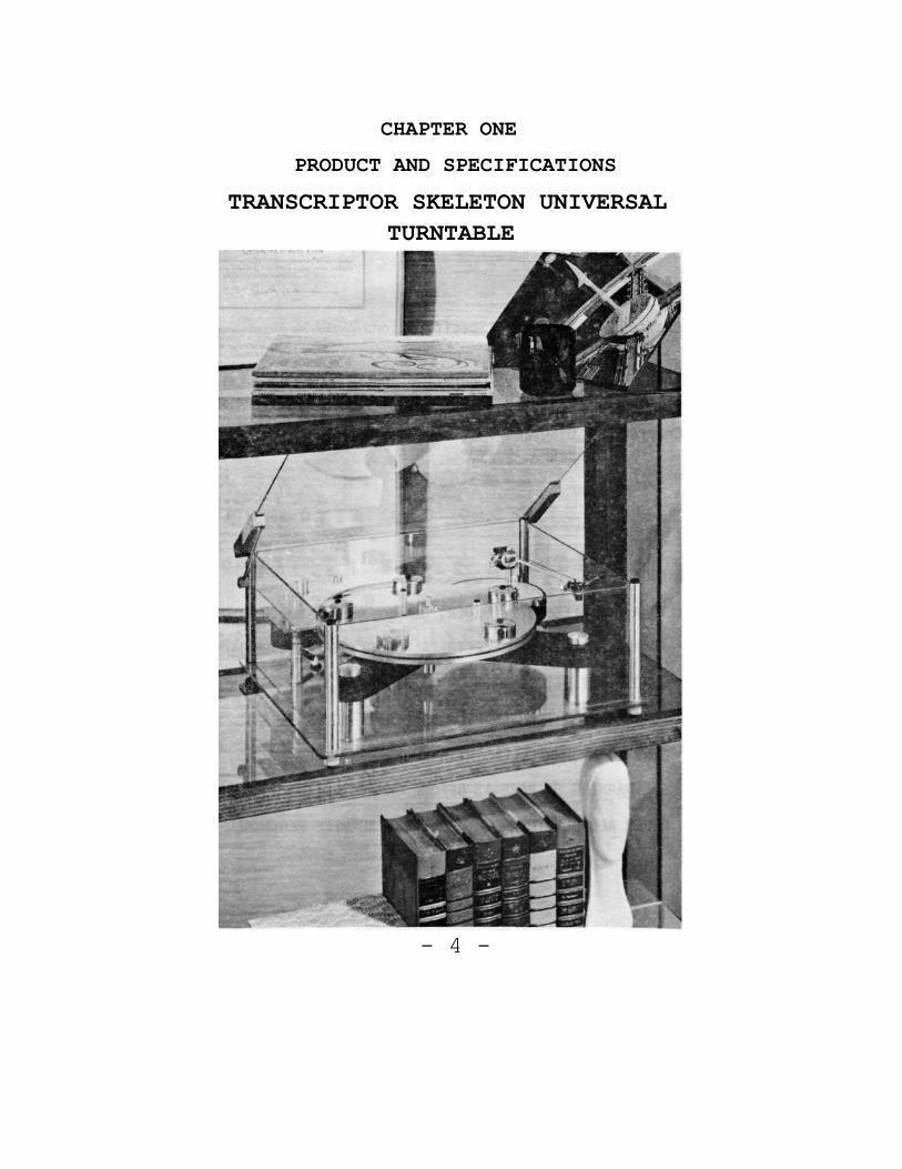
CHAPTER ONE
PRODUCT AND SPECIFICATIONS TRANSCRIPTOR SKELETON UNIVERSAL
TURNTABLE
- 4 -

THE TRANSCRIPTOR SKELETON UNIVERSAL TURNTABLE
THE TRANSCRIPTOR SKELETON UNIVERSAL TURNTABLE EMPLOYS A LOW SPEED SYNCHRONOUS MOTOR ON A SPRING-SUSPENSION MOTOR BOARD. THE PLATTER IS DRIVEN BY A RUBBER BELT PROVIDING THE BEST INSULATION AGAINST VIBRATION AND RUMBLE. IN ORDER TO ELIMINATE ANY MECHANICAL OR ELECTRICAL SHOCK TO THE EQUIPMENT, THE ON-OFF SWITCHING IS ACCOMPLISHED BY MEANS OF A MAGNETICALLY ACTUATED REED SWITCH WHICH ASSURES LONG TROUBLE-FREE LIFE.
SPECIFICATIONS
TRANSCRIPTOR SKELETON UNIVERSAL TURNTABLE: Platter: 12" (305mm) Diameter, Cast and Machined.
Aluminum Alloy, with 5 silver-plated weights, approximately 6.5 pounds.
Main Bearing: Slim section ball-ended ground and polished steel, supported on a hardened steel thrust plate. Bushing coated with P.T.F.E. (Polytetrafluoroethylene) A material having a lower co-efficient of friction than any other solid.
Motor: 10 Pole Synchronous, Split-Phase, 720 R.P.M. Power: 117 Volt A.C., 60 HZ .038 A
Wow & Flutter: .05%
Speeds: 33 1/3 and 45 r.p.m.
Rumble: NIL
Dimensions: 18" wide x 151/2" deep, x 7” high.
- 5 -
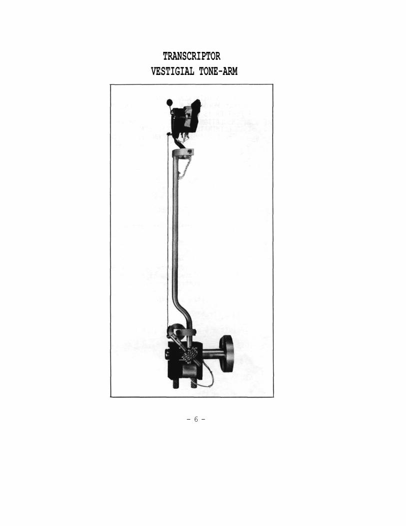
TRANSCRIPTOR VESTIGIAL TONE-ARM
- 6 -
THE TRANSCRIPTOR VESTIGIAL TONE-ARM
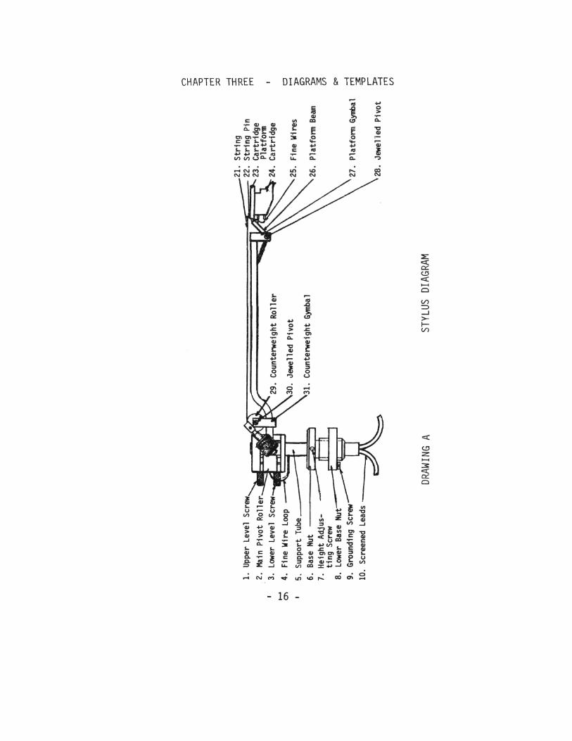
THE MAIN HORIZONTAL PIVOTS CARRY A MAIN HORIZONTAL SWINGING ARM, WITH NO POSSIBILITY OF VERTICAL MOTION. AT THE FRONT END OF THIS MAIN ARM IS ATTACHED A VERY SHORT (VESTIGIAL) ARM, PIVOTALLY MOUNTED TO PROVIDE THE VERTICAL MOVEMENT, AND TO WHICH THE CARTRIDGE IS MOUNTED. THE COUNTERWEIGHT IS MOUNTED ON THE MAIN HORIZONTAL ARM, NEAR THE MAIN PIVOTS, WHERE IT CONTROLS THE ACTION OF THE VESTIGIAL ARM BY MEANS OF A STRING AND ROLLER MECHANISM.
SPECIFICATIONS
TRANSCRIPTOR VESTIGIAL TONE ARM
Pivot to Stylus: 1 3/8" Overall Length: 8 3/4" Mounting Shaft Diameter: 5/8" Vertical Adjustment: 2 1/2" Lead Capacitance: 99pf per cable
Recommended Cartridge type: Weight not greater than 7 grams. Capable of tracking at less than 2 grams. Compliance of 30 cms/dyne x 10-6 or higher.
- 7 -
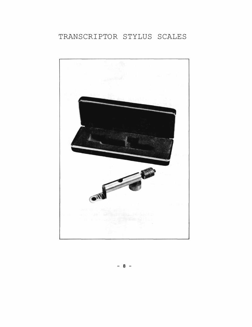
TRANSCRIPTOR STYLUS SCALES
- 8 -
THE TRANSCRIPTOR STYLUS SCALES
OF BRITISH DESIGN, THIS SUPERB INSTRUMENT WEIGHS ACCURATELY THE DOWNWARD STYLUS FORCE OF ANY PICK-UP ARM, DESIGNED TO TRACK AT LEAST 5 GRAMS OR LESS.
OF PURE BALANCED BEAM CONSTRUCTION, INCORPORATING A BUBBLE BALANCE INDICATOR, AND A PRECISELY MADE UNIPIVOT, THIS UNIT IS DESIGNED TO WEIGH FROM 0-5 GRAMS IN l/20th GRAM INCREMENTS. THE BALANCE IS SENSITIVE TO l/100th OF A GRAM, AND IS CAPABLE OF ACHIEVING AN OVERALL WEIGHING ACCURACY OF BETTER THAN l/50th OF A GRAM.
THIS IS A COMPLETELY NEW CONCEPT IN THE DESIGN OF SUCH A DEVICE, SUCH ACCURACY HAVING PREVIOUSLY BEEN ACHIEVED ONLY BY THOSE MANUFACTURERS USING EXPENSIVE LABORATORY BALANCE EQUIPMENT.
CORRECT STYLUS PRESSURE IN ACCORDANCE WITH THE RECOMMENDATIONS OF THE CARTRIDGE MANUFACTURER IS MOST IMPORTANT AND TODAY'S PRESSURES ARE SO SMALL THAT THEY MAY BE CORRECTLY SET AND MEASURED BY USING ONLY THE TRANSCRIPTOR STYLUS SCALES.
EACH SCALE IS SUPPLIED WITH A PAIR OF TWEEZERS, INSTRUCTIONS AND THE FOLLOWING WEIGHTS:
2 - 2 Gram weights 1 - 1 Gram weight 1 - 1/2 Gram weight 2 - 1/5 Gram weights 1 - 1/10 Gram weight 1 - 1/20 Gram weight
- 9 -
CHAPTER TWO: ASSEMBLY, OPERATION & MAINTENANCE INSTRUCTIONS FOR SETTING UP THE SKELETON TURNTABLE
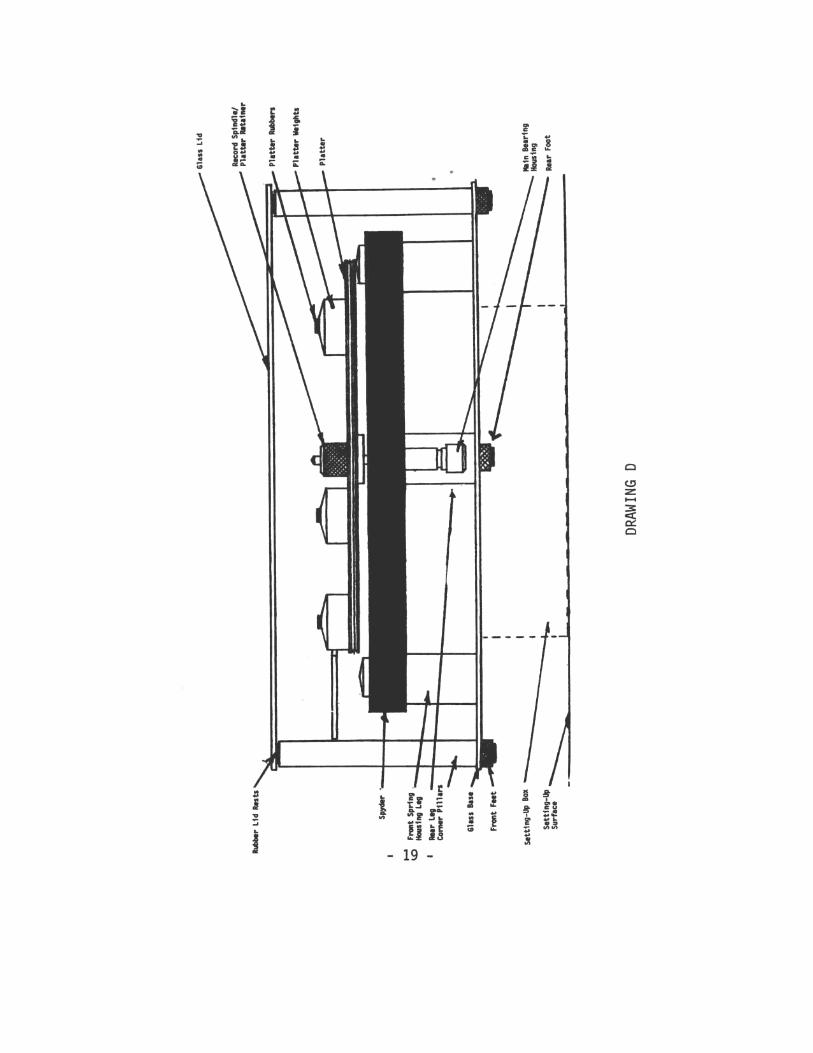
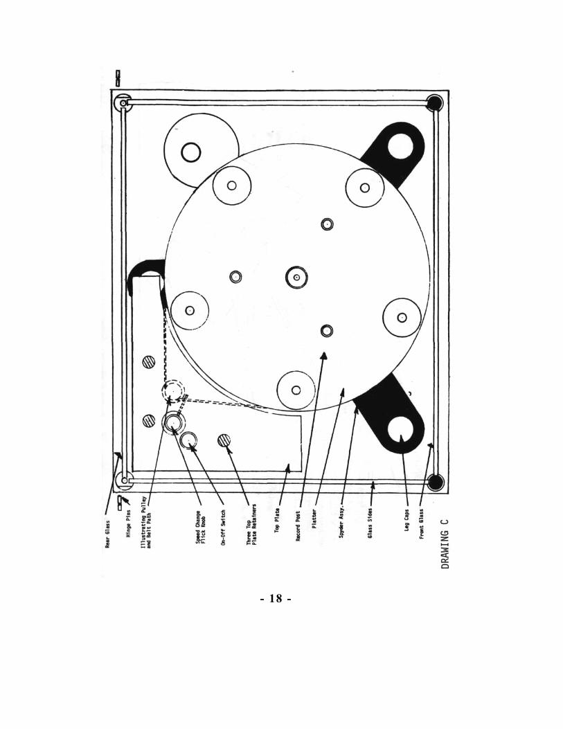
(See Drawings C and D on Pages 18 and 19) After removing the unit from its carton, remove the masonite board from the unit, taking great care not to scratch the platter which is attached to the underside of the board.
The Vestigial Arm will be found packed separately. As this Arm incorporates delicate vee jewelled pivots which could crack during transit, great care has been taken to pro-tect it from damage.
Setting up the turntable and arm is made easy by mounting the turntable on a box (or on two thick telephone directories, which are ideal.)
To further facilitate setting up and cleaning, remove the four corner thumbnuts from underneath the four corner posts. This will allow the removal of the glass sides and 4 posts as one unit. Note that the two FRONT corner thumbnuts act as feet and are fitted with rubber discs, the unit does not rest on the rear corner thumbnuts, but on the center foot.
Make sure the unit is level when setting up.
Remove the top plate which covers the motor by unscrewing the three top plate retaining nuts. Note that the on-off switch holds a small magnet which rotates to activate a reed switch to switch the unit on or off, thus the unit cannot operate without replacing the top plate. Remove the platter from the masonite board and place the platter onto the main spindle, first making sure that the mating surfaces are absolutely clean. Secure the platter with the platter retainer. Note that if the spindle is removed from the bearing, the steel ball onto which the spindle runs, can easily be lost. Make sure at all times that this ball is in its place before operating the unit. This main spindle requires oiling with a few drops of thin oil, once or twice each year, and is the only servicing the
- 10 -
unit should require, apart from replacing the belt, (See Page 15 on routine maintenance).
The drive belt may now be attached, as shown on the illustration, and the top plate may be resecured. After fitting a suitable plug to the mains lead, the unit is ready to operate.
Operation is simple, merely turn the on-off switch in either direction until the platter rotates. To change speed, pull the speed change knob up to operate 33 R.P.M., push it down to obtain 45 R.P.M.
Now set up the arm as per the instructions starting on the next page.
Once the arm is set up, clean and replace the glass sides and the four thumbscrews under the glass base. Remember that the two thumbscrews with rubber feet belong under the FRONT posts. Remove the two hinge pins, from the two rear posts and pass them through the holes on the side of the hinge blocks attached to the dust cover, and screw into the two rear posts. Use caution not to cross-thread the hinge pins. Note that the hinge stay mechanism is spring loaded. On opening the lid, the stay will automatically follow the lid and slip into place into the slot in the left hand hinge block. To lower the lid, lift the lid slightly, lower the stay until it clears the slot, then lower the lid.
A sparkling Skeleton turntable makes a gratifying sight. The glass should be cleaned with water or a suitable glass cleaner. Once cleaned the glass remains clean for a long period, unlike plastic substitutes. Do not use metal polish, this is abrasive, and can remove plated and anodised surfaces.
- 11 -
SET UP INSTUCTIONS FOR THE
TRANSCRIPTOR TONE-ARM
(See Drawings A and B on Pages 16 and 17)
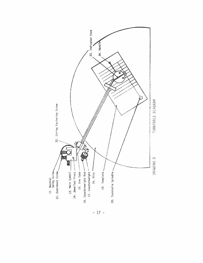
If the Transcriptor Vestigial Tone-Arm is being mounted on other than the Transcriptor Skeleton Turntable, use the template provided to determine the mounting position on your base. It is imperative that your Turntable be absolutely level before attempting any of the adjustments. Also, note additional directions on the template.
Alignment of the Tone-Arm involves five different adjustments: 1. Overhang adjustment, 2. Horizontal adjustment, 3. Height adjustment, 4. Overshoot and anti-skating adjustment and 5. Tracking force adjustment. Each step is detailed below. Please read each step completely before attempting the adjustment.
I. OVERHANG ADJUSTMENT: Place a less valuable record on the turntable and place the template provided on the center post and position the stylus as shown in the picture. If the arm height is low, preventing the arm from swinging over the record, loosen the height adjustment screw (7) on the base nut (6) and raise the arm to a point where the arm tube is approximately 1" (25mm) above the record surface. A more exacting height adjustment will be made later. Rotate the Arm mounting disc so the line (33) scribed on the top of the cartridge platform (23) is parallel with the lines on the template. Once the arm is adjusted, the lower base nut (8) may be tightened finger-tight. The ground wire located underneath the arm mounting disc should be attached to the ground screws (9) on the lower base nut. Resecure the three thumb nuts holding the arm mounting disc.
- 12 -
2. HORIZONTAL ADJUSTMENT: A free and neutral swing of the tone arm in the horizontal is ESSENTIAL to the correct operation of the Vestigial arm. With the stylus resting at the beginning of the record, adjust the upper and lower leveling screws (1 & 3) to bring the arm tube approximately parallel to the record surface when viewed from the side. Note that both of the leveling screws must be loosened before either can effect the adjustment. Now adjust the counterweight (17) to a negative pressure, so the stylus does not contact the record. If the arm has a tendency to swing inward or out- ward, adjust the neutral swing screw (11) to eliminate this tendency. Then recheck the arm tube to make sure it is still parallel with the record. It may be necessary to adjust the upper & lower leveling screws slightly to obtain a neutral swing of the arm if a neutral swing cannot be obtained with the neutral swing screw alone.
3. HEIGHT ADJUSTMENT: Once again, add weight to the cartridge so the stylus is in contact with the record, loosen the height adjustment screw (7) and adjust the height of the arm until the cartridge platform (23) is parallel to the record surface.
4. OVERSHOOT ADJUSTMENT: Adjust the overshoot screw (12) to allow the stylus to freely track the lead out grooves, but limit travel so not to track onto the record label. This is a very fine adjustment. Only a small turn on the screw will severely effect the movement of the arm.
WARNING OVERTIGHTENING, OR ABUSIVE USE OF ANY OF THE ARM ADJUSTMENTS WILL DAMAGE THE HORIZONTAL PIVOTS. DO NOT SECURE THE ARM BY THIS METHOD FOR TRANS-PORTING. DAMAGE OF THE PIVOTS FROM THE ABOVE MISUSE WILL NOT BE COVERED UNDER THE WARRANTY.
- 13 -
5. TRACKING FORCE ADJUSTMENT: Check to make sure the counterweight rod (16) is at a 45° angle while the stylus is resting on the record. If it is not, loosen the set screw at the tip of the counterweight rod (16) and reposition the assembly. Set the tracking force by adjusting the counterweight (17) to a NEGATIVE pressure, and slowly (1/4 turn at a time) INCREASE the pressure until your stylus will track a variety of records without tracking distortion. Alternatively, use the only set of scales remotely capable of measuring Vestigial pressures, the Transcriptor stylus scale. As a final check, observe and reset, if necessary, step 3 and be sure the counterweight shaft is at a 45° angle with the stylus resting on the record.
INSTRUCTIONS FOR USE OF
THE TRANSCRIPTOR SCALES
When weighing or setting, the scales should always be used at right angles to the arm. Place weights equal to the required downward force centrally on the rubber pad on the scales platform, stacking the weights where required. The scales should then be balanced by means of the threaded cursor, until the bubble is centrally positioned. Remove the weights and place the stylus tip on the rubber pad. Adjust the pickup arm conterweight until the bubble once again takes up a central position. The comparison is now complete, and the stylus force is correct. It should be noted that it takes only 1/10th of a gram to deflect the bubble completely off the scale.
- 14 -
MAINTENANCE
As the Transcriptor Skeleton Turntable is virtually maintenance free, only a periodic inspection of the main drive belt and center bearing is necessary. Remove the switch plate and belt, then remove the platter assembly being careful not to damage the tone arm. Use caution not to lose the ball bearing which may come out attached to the lower end of the spindle. Inspect the bearing shaft for dirt or signs of scoring; clean with a soft rag and any alcohol based cleaner. Remove the lower cap on the bearing housing and remove the old oil from inside. With a cotton swab, clean out the inside walls of the bearing housing; then re-lubricate the shaft and the thrust plate with a very small amount of light weight phono oil. (Do not use 3 in 1 oil.) Reassemble the thrust plate and cap and install the ball bearing from the top of the bearing housing, and install the platter. If the belt or any other of the parts show signs of wear, replace. Your local dealer can supply any part necessary, or contact the importer, whose name appears in the front of this book.
- 15 -
- 18 -