OWNEr'S MaNuaL detail, ruggedly built parts and a rigid quality control program assure safe and...
28
MODEL W1736 OvErarM rOutEr Phone: 1-360-734-3482 • On-Line technical Suppor t: [email protected] COPYrIGHt © OCtOBEr, 2004 BY WOODStOCK INtErNatIONaL, INC. rEvISED auGuSt, 2010 (tr) WarNING: NO POrtION OF tHIS MaNuaL MaY BE rEPrODuCED IN aNY SHaPE Or FOrM WItHOut tHE WrIttEN aPPrOvaL OF WOODStOCK INtErNatIONaL, INC. Printed in taiwan #6617tr OWNEr'S MaNuaL (FOR MODELS MANUFACTURED SINCE 8/10)
Transcript of OWNEr'S MaNuaL detail, ruggedly built parts and a rigid quality control program assure safe and...

MODEL W1736 OvErarM rOutEr
Phone: 1-360-734-3482 • On-Line technical Support: [email protected]
COPYrIGHt © OCtOBEr, 2004 BY WOODStOCK INtErNatIONaL, INC. rEvISED auGuSt, 2010 (tr)WarNING: NO POrtION OF tHIS MaNuaL MaY BE rEPrODuCED IN aNY SHaPE Or FOrM WItHOut
tHE WrIttEN aPPrOvaL OF WOODStOCK INtErNatIONaL, INC.Printed in taiwan#6617tr
OWNEr'S MaNuaL(FOR MODELS MANUFACTURED SINCE 8/10)

This manual provides critical safety instructions on the proper setup, operation, maintenance and service of this machine/equipment.
Failure to read, understand and follow the instructions given in this manual may result in serious personal injury, including amputation, electrocution or death.
The owner of this machine/equipment is solely responsible for its safe use. This responsibility includes but is not limited to proper installa-tion in a safe environment, personnel training and usage authoriza-tion, proper inspection and maintenance, manual availability and comprehension, application of safety devices, blade/cutter integrity, and the usage of personal protective equipment.
The manufacturer will not be held liable for injury or property damage from negligence, improper training, machine modifications or misuse.
Some dust created by power sanding, sawing, grinding, drilling, and other construction activities contains chemicals known to the State of California to cause cancer, birth defects or other reproductive harm. Some examples of these chemicals are:
• Lead from lead-based paints.• Crystalline silica from bricks, cement and other masonry products.• Arsenic and chromium from chemically-treated lumber.
Your risk from these exposures varies, depending on how often you do this type of work. To reduce your exposure to these chemicals: Work in a well ventilated area, and work with approved safety equip-ment, such as those dust masks that are specially designed to filter out microscopic particles.

USE THE QUICK GUIDE PAGE LABELS TO SEARCH OUT INFORMATION FAST!
SET UP
MA
INTEN
AN
CEPA
RTSW
ARRA
NTY
OPERA
TION
SSA
FETYIN
TROD
UCTIO
NTable of ContentsINTRODUCTION ..................................................................................................2
Woodstock Technical Support ............................................................................ 2About Your New Overarm Router ........................................................................ 2Specifications ............................................................................................... 2Controls and Features ..................................................................................... 3
SAFETY ............................................................................................................4Standard Machinery Safety ............................................................................... 4Additional Safety Instructions for Overarm Routers .................................................. 6
SET UP ............................................................................................................7Unpacking ................................................................................................... 7Items Needed for Set Up .................................................................................. 7Cleaning Parts .............................................................................................. 7Inventory .................................................................................................... 8Assembling Overarm Router .............................................................................. 9Mounting ................................................................................................... 10Attaching Foot Switch ................................................................................... 11Installing Router .......................................................................................... 12Aligning Router with Table Pin ......................................................................... 13Connecting to Air ......................................................................................... 14Test Run .................................................................................................... 14
OPERATIONS ................................................................................................... 15General .................................................................................................... 15Adjusting Valves .......................................................................................... 15Adjusting Plunge Depth ................................................................................. 16Using Table Pins .......................................................................................... 17
MAINTENANCE ................................................................................................. 18General .................................................................................................... 18Table ....................................................................................................... 18Lubrication ................................................................................................ 18Troubleshooting........................................................................................... 19
PARTS BREAKDOWN .......................................................................................... 20WARRANTY ..................................................................................................... 22

-2-
INTR
OD
UCT
ION
W1736 Overarm Router (Mfg. 8/10+)
SpecificationsTable ................................................................. 19-3/4" W x 14" D x 1-3/8" ThickOverall Height .................................................................................... 31-3/8"Overall Width ..................................................................................... 21-3/4" Overall Depth ..................................................................................... 28-1/4"Footprint ......................................................................... 21-3/4" W x 28-1/4" DMachine Weight .................................................................................... 56 lbsMaximum Head Stroke .............................................................................5-1/2"Maximum Distance Spindle to Table .............................................................6-1/2"Maximum Distance Housing to Table ............................................................8-3/4"Throat Capacity ....................................................................................... 18"Router Adapter Sizes ......................................................... 3.25", 3.328", 3.5", 4.2"Router Housing Size ................................................................................4-1/2"Table Pins (3) .................................................3/16" x 1/4", 5/16" x 3/8", 7/16" x 1/2"Table Construction ..............................................................Milled Cast AluminumBody Construction ......................................................................Cast AluminumClamp Housing ...........................................................................Cast AluminumRequired Operating Air Pressure ................................................................ 60 PSIMaximum Air Pressure ........................................................................... 115 PSI
Woodstock Technical SupportThis machine has been specially designed to provide many years of trouble-free service. Close attention to detail, ruggedly built parts and a rigid quality control program assure safe and reliable operation.
Woodstock International, Inc. is committed to customer satisfaction. Our intent with this manual is to include the basic information for safety, setup, operation, maintenance, and service of this product.
We stand behind our machines! In the event that questions arise about your machine, please contact Woodstock International Technical Support at (360) 734-3482 or send e-mail to: [email protected]. Our knowledgeable staff will help you troubleshoot problems and process warranty claims.
INTRODUCTION
If you need the latest edition of this manual, you can download it from http://www.shopfox.biz. If you have comments about this manual, please contact us at:
Woodstock International, Inc.Attn: Technical Documentation Manager
P.O. Box 2309Bellingham, WA 98227
Email: [email protected]

-3-
INTRO
DU
CTION
W1736 Overarm Router (Mfg. 8/10+)
Controls and Features
A. Top Valve: Controls the speed that the router rises from the plunge (down) position.
B. Bottom Valve: Controls the plunge speed of the router.
C. Head: The part of the overarm assembly that houses the router motor and moves up and down when activated by the foot pedal.
D. Pin Adjustment Knob: Locks the table pin in place for pin routing operations.
E. Foot Switch: When connected to air, controls the up and down motion of the head.
F. Router Motor Adapters: Allows various sizes and brands of router motors to be installed on the overarm assembly.
G. Plunge Depth Knob: Adjusts the plunging depth of the head.
A
B
E
D
C
F
G

-4-
SAFE
TYW1736 Overarm Router (Mfg. 8/10+)
SAFETY Standard Machinery SafetySAFETY
READ MANUAL BEFORE OPERATING MACHINE.FAILURE TO FOLLOW INSTRUCTIONS BELOW WILL
RESULT IN PERSONAL INJURY.
Standard Safety Instructions1. READ THROUGH THE ENTIRE MANUAL BEFORE STARTING MACHINERY. Machinery presents serious
injury hazards to untrained users.
2. ALWAYS USE ANSI APPROVED SAFETY GLASSES WHEN OPERATING MACHINERY. Everyday eye-glasses only have impact resistant lenses—they are NOT safety glasses.
3. ALWAYS WEAR A NIOSH APPROVED RESPIRATOR WHEN OPERATING MACHINERY THAT PRODUCES
DUST. Wood dust is a carcinogen and can cause cancer and severe respiratory illnesses.
4. ALWAYS USE HEARING PROTECTION WHEN OPERATING MACHINERY. Machinery noise can cause permanent hearing damage.
5. WEAR PROPER APPAREL. DO NOT wear loose clothing, gloves, neckties, rings, or jewelry which may get caught in moving parts. Wear protective hair covering to contain long hair and wear non-slip footwear.
6. NEVER OPERATE MACHINERY WHEN TIRED, OR UNDER THE INFLUENCE OF DRUGS OR ALCOHOL. Be mentally alert at all times when running machinery.
7. ONLY ALLOW TRAINED AND PROPERLY SUPERVISED PERSONNEL TO OPERATE MACHINERY. Make sure operation instructions are safe and clearly understood.
8. KEEP CHILDREN AND VISITORS AWAY. Keep all children and visitors a safe distance from the work area.
9. MAKE WORKSHOP CHILD PROOF. Use padlocks, master switches, and remove start switch keys.
Indicates an imminently hazardous situation which, if not avoided, WILL result in death or serious injury.
Indicates a potentially hazardous situation which, if not avoided, COULD result in death or serious injury.
Indicates a potentially hazardous situation which, if not avoided, MAY result in minor or moderate injury.
This symbol is used to alert the user to useful information about proper operation of the equipment, and/or a situation that may cause damage to the machinery.
NOTICE

-5-
SAFETY
W1736 Overarm Router (Mfg. 8/10+)
10. NEVER LEAVE WHEN MACHINE IS RUNNING. Turn power OFF and allow all moving parts to come to a complete stop before leaving machine unattended.
11. DO NOT USE IN DANGEROUS ENVIRONMENTS. DO NOT use machinery in damp, wet locations, or where any flammable or noxious fumes may exist.
12. KEEP WORK AREA CLEAN AND WELL LIT. Clutter and dark shadows may cause accidents.
13. USE A GROUNDED EXTENSION CORD RATED FOR THE MACHINE AMPERAGE. Undersized cords over-heat and lose power. Replace extension cords if they become damaged. DO NOT use extension cords for 220V machinery.
14. ALWAYS DISCONNECT FROM POWER SOURCE BEFORE SERVICING MACHINERY. Make sure switch is in OFF position before reconnecting.
15. MAINTAIN MACHINERY WITH CARE. Keep blades sharp and clean for best and safest performance. Follow instructions for lubricating and changing accessories.
16. MAKE SURE GUARDS ARE IN PLACE AND WORK CORRECTLY BEFORE USING MACHINERY.
17. REMOVE ADJUSTING KEYS AND WRENCHES. Make a habit of checking for keys and adjusting wrenches before turning machinery ON.
18. CHECK FOR DAMAGED PARTS BEFORE USING MACHINERY. Check for binding and alignment of parts, broken parts, part mounting, loose bolts, and any other conditions that may affect machine operation. Repair or replace damaged parts.
19. USE RECOMMENDED ACCESSORIES. Refer to the instruction manual for recommended accessories. The use of improper accessories may cause risk of injury.
20. DO NOT FORCE MACHINERY. Work at the speed for which the machine or accessory was designed.
21. SECURE WORKPIECE. Use clamps or a vise to hold the workpiece when practical. A secured workpiece protects your hands and frees both hands to operate the machine.
22. DO NOT OVERREACH. Keep proper footing and balance at all times.
23. MANY MACHINES WILL EJECT THE WORKPIECE TOWARD THE OPERATOR. Know and avoid condi-tions that cause the workpiece to "kickback."
24. ALWAYS LOCK MOBILE BASES (IF USED) BEFORE OPERATING MACHINERY.
25. BE AWARE THAT CERTAIN DUST MAY BE HAZARDOUS to the respiratory systems of people and animals, especially fine dust. Make sure you know the hazards associated with the type of dust you will be exposed to and always wear a respirator approved for that type of dust.

-6-
SAFE
TYW1736 Overarm Router (Mfg. 8/10+)
Additional Safety Instructions for Overarm Routers
USE this and other machinery with caution and respect. Always consider safety first, as it applies to your individual working conditions. No list of safety guidelines can be complete—every shop environment is different. Failure to follow guidelines could result in serious personal injury, damage to equipment or poor work results.
READ and understand this entire instruction manual before using this machine. Serious personal injury may occur if safety and operational information is not understood and fol-lowed. DO NOT risk your safety by not reading!
1. READ THE ROUTER MANUAL. Read and understand the instruction manual that was included with the router you intend to install. If you do not understand the safety and operation instructions for your router, do not install it on the Model W1736.
2. ROUTER INSTALLATION. Make sure the installed router is tightly secured in the housing before turning it ON.
3. PLUNGE DEPTH. Always check the plunge depth with the router turned OFF to make sure that an installed router bit will not contact the table when the foot switch is pressed and the router is running.
4. GUARDS. Make sure all guards are in place during operation. If you remove them for cleaning, replace them immediately. If guards become cracked, replace them immediately before operating the Model W1736 again.
5. AVOIDING CONTACT WITH ROUTER BIT. • NeverplaceyourhandundertherouterwhiletherouterisON or when plunging the router.• Neverattemptaroutingoperationthatwillbringanypartofyourhand/fingerswithin12"of
the spinning router bit. • Iftheworkpieceistoosmall,buildaclampingjigtoholdinplace,orusealongerworkpiece
and cut to size after routing.• Usethetablepin.Thetablepinguidestheworkpieceinapredictablemannerandgreatly
increases operator control in the event of a kickback or climb cut.
6. PATTERN ROUTING. Test all patterns with the table pin to make sure that the pattern template works before attempting to rout your workpiece.

SET UP
-7-
W1736 Overarm Router (Mfg. 8/10+)
This machine has been carefully packaged for safe trans-portation. If you notice the machine has been damaged during shipping, please contact your authorized Shop Fox dealer immediately.
READ and understand this entire instruc-tion manual before using this machine. Serious personal injury may occur if safety and operational information is not understood and followed. DO NOT risk your safety by not reading!
UnpackingSET UP
The following items are needed, but not included, to setup your machine:
• AirCompressor .............................................1• AirHosewith3/8"FemaleQuickConnectFitting ...1• HexWrench6mm ..........................................1• HexWrench8mm ..........................................1• PhillipsScrewdriver .......................................1• Open-EndWrench12mm .................................1• Open-EndWrench17mm .................................1• Router w/Removable Base ...............................1• MountingHardwareSpecifictoApplication .....Varies
Items Needed for Set Up
Cleaning PartsThe table and other unpainted parts of your overarm router are coated with a waxy grease that protects them from corrosion during shipment.
Clean this grease off with a solvent cleaner or citrus-based degreaser. DO NOT use chlorine-based solvents such as brake parts cleaner or acetone—if you happen to splash some onto a painted surface, you will ruin the finish.
MAKE your shop “child safe.” Ensure that your workplace is inaccessible to youngsters by closing and locking all entrances when you are away. NEVER allow untrained visitors in your shop when assem-bling, adjusting or operat-ing equipment.

-8-
SET
UP
W1736 Overarm Router (Mfg. 8/10+)
NOTICEWhen ordering replacement parts, refer to the parts list and diagram in the back of the manual.
The following is a description of the inventory of the components shipped with the SHOP FOX® Model W1736. Lay the components out and inventory your ship-ment.
Main Inventory Components (Figure 1)A. Table .........................................................1B. Support Arm ................................................1C. Router Adapters ...........................................4
• 3.25" (fits many Makita)• 3.328"(fitsmanyMilwaukee)• 3.5"(fitsmanyBosch,Porter-Cable,&Makita)• 4.2"(fitsmanyPorter-Cable)
D. Head Assembly .............................................1E. Foot Switch Assembly .....................................1F. Router Safety Guard ......................................1G. Front Guard ................................................1H. Side Guard ..................................................1
Part and Fastener Hardware (Figure 2)I. Table Pin Knob Bolt .......................................1J. Rubber Gasket .............................................1K. Table Pins ...................................................3 L. Rubber Washer 11mm .....................................1M. Round Adjustment Nuts M10-1.5 ........................2N. Hardware Bag ..............................................1
• CapScrewsM10-1.5x45 ..............................4• CapScrewsM10-1.5x25 ..............................4• LockWashers10mm ....................................8• FlatHeadScrewsM5-.8x10 ..........................4• LockNutM10-1.5 .......................................1• ThumbScrewM5-.8x10 ..............................2• PlasticWashers5mm ...................................2• FlangeScrewM4-.7x12 ...............................1
O. Cord Loop 5/8" .............................................1P. Shaft Screw .................................................1 If any parts appear to be missing, examine the packag-ing carefully to be sure those parts are not among the packing materials. If any parts cannot be found, find the part number in the back of this manual and contact Woodstock International, Inc. at 360-734-3482 or at [email protected]
Inventory
Figure 1. Main inventory components.
SUFFOCATION HAZARD!
Immediately discard all plastic bags and packing materials to eliminate choking/suf-focation hazards for children and animals.
Figure 2. Part and fastener hardware.
AB
CD
EF
G
H
I
JK
NM
L
O
P
SET UP
-9-
W1736 Overarm Router (Mfg. 8/10+)
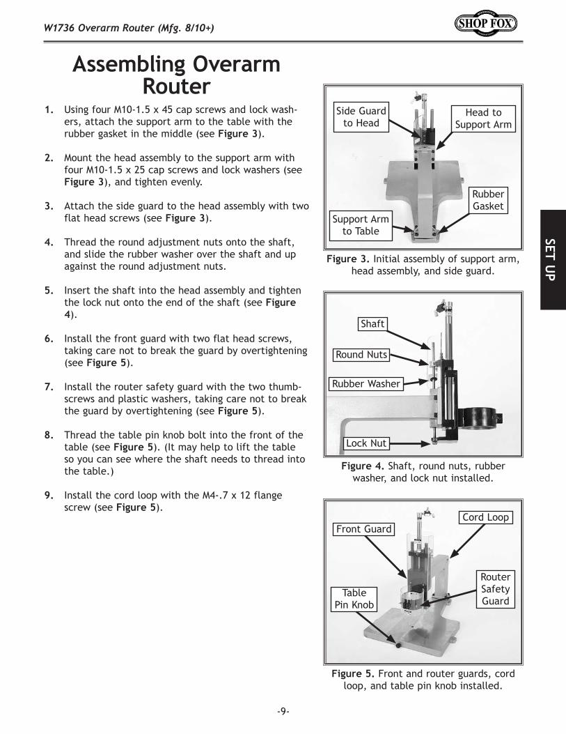
1. Using four M10-1.5 x 45 cap screws and lock wash-ers, attach the support arm to the table with the rubber gasket in the middle (see Figure 3).
2. Mount the head assembly to the support arm with four M10-1.5 x 25 cap screws and lock washers (see Figure 3), and tighten evenly.
3. Attach the side guard to the head assembly with two flat head screws (see Figure 3).
4. Thread the round adjustment nuts onto the shaft, and slide the rubber washer over the shaft and up against the round adjustment nuts.
5. Insert the shaft into the head assembly and tighten the lock nut onto the end of the shaft (see Figure 4).
6. Install the front guard with two flat head screws, taking care not to break the guard by overtightening (see Figure 5).
7. Install the router safety guard with the two thumb-screws and plastic washers, taking care not to break the guard by overtightening (see Figure 5).
8. Thread the table pin knob bolt into the front of the table (see Figure 5). (It may help to lift the table so you can see where the shaft needs to thread into the table.)
9. Install the cord loop with the M4-.7 x 12 flange screw (see Figure 5).
Assembling Overarm Router
Figure 3. Initial assembly of support arm, head assembly, and side guard.
Figure 4. Shaft, round nuts, rubber washer, and lock nut installed.
Figure 5. Front and router guards, cord loop, and table pin knob installed.
Head to Support Arm
Side Guard to Head
Support Arm to Table
Shaft
Round Nuts
Rubber Washer
Lock Nut
Cord LoopFront Guard
Router Safety Guard
Table Pin Knob
Rubber Gasket
-10-
SET
UP
W1736 Overarm Router (Mfg. 8/10+)
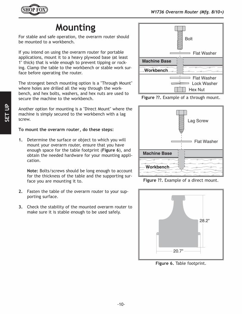
For stable and safe operation, the overarm router should be mounted to a workbench.
If you intend on using the overarm router for portable applications, mount it to a heavy plywood base (at least 1" thick) that is wide enough to prevent tipping or rock-ing. Clamp the table to the workbench or stable work sur-face before operating the router.
The strongest bench mounting option is a "Through Mount" where holes are drilled all the way through the work-bench, and hex bolts, washers, and hex nuts are used to secure the machine to the workbench.
Another option for mounting is a "Direct Mount" where the machine is simply secured to the workbench with a lag screw.
To mount the overarm router, do these steps:
1. Determine the surface or object to which you will mount your overarm router, ensure that you have enough space for the table footprint (Figure 6), and obtain the needed hardware for your mounting appli-cation.
Note: Bolts/screws should be long enough to account for the thickness of the table and the supporting sur-face you are mounting it to.
2. Fasten the table of the overarm router to your sup-porting surface.
3. Check the stability of the mounted overarm router to make sure it is stable enough to be used safely.
Mounting
20.7"
28.2"
Figure 6. Table footprint.
Machine Base
Workbench
Bolt
Flat Washer
Flat WasherLock Washer
Hex Nut
Figure ??. Example of a through mount.
Machine Base
Workbench
Lag Screw
Flat Washer
Figure ??. Example of a direct mount.

SET UP
-11-
W1736 Overarm Router (Mfg. 8/10+)
Figure 7. Hose/port labels on foot switch, as viewed straight on.
Figure 8. Air hose attachment locations.
The foot switch attaches to the valves on the overarm router assembly with the two small air hoses. The air hose ports at the foot switch are labeled "R" and "S", as shown in Figure 7.
To attach the foot switch, do these steps:
1. Attach the hose connected to port "R" to the top valve (see Figure 8) on the air cylinder by pushing the hose into the fitting.
2. Attach the hose connected to port "S" to the bottom valve on the air cylinder by pushing the hose into the fitting.
Attaching Foot Switch
R S
Top Valve
Bottom Valve

-12-
SET
UP
W1736 Overarm Router (Mfg. 8/10+)
The adapters included with the Model W1736 are designed for most common sizes of Makita, Milwaukee, Bosch, Porter-Cable, and Dewalt routers that have detachable bases.
To install a router motor into the overarm router assembly, do these steps:
1. Remove your router motor from its base and mea-sure the diameter of the router motor or the base from which it was removed. (If your router size does not closely match any of the adapters, you may not be able to safety mount your router motor on the Model W1736.)
2. Slide the correct size adapter over the router motor, as shown in Figure 9, aligning any pins in the router with the slots in the adapter and making sure that the adapter lip is toward the top part of the router.
Note: The adapter must have a snug fit all the way around the router body or it will not secure to the housing properly. Refer to Figure 10 to ensure a proper fit.
3. Insert the router motor/adapter assembly into the housing on the overarm router assembly.
4. Using a 6mm hex wrench, tighten the cap screw at the front of the housing to secure the router motor (see Figure 11).
5. Check that the router motor is tightly secured in the housing by pulling on it to see if it can be pulled out of the housing.
• Iftheroutermotorislooseorcanbepulledoutof the housing, then it is not fastened correctly or installed with the correct adapter. Remove the router and try refastening it, or remeasure your router and ensure that you are using the correct adapter.
• Iftheroutermotorcannotbepulledoutbyhand,then proceed with the rest of the setup process.
Note: If the router is contacting the table in the down position, adjust the plunge depth knob (see Page 3) so the router will not contact the table in the down posi-tion.
Installing Router
Figure 9. Fitting correct size adapter onto router motor.
Figure 11. Router motor secured in overarm assembly.
Cap Screw
Figure 10. Illustration of a good vs. bad fit between router motor and adapter.
RouterMotor
Adapter
GOOD FIT
RouterMotor
Adapter
BAD FIT

SET UP
-13-
W1736 Overarm Router (Mfg. 8/10+)
The router motor must be aligned with the table pin to ensure accurate work during pin routing operations.
To check/align the router to the table pin, do these steps:
1. Install a 1/4" straight bit into the router.
2. Insert the 1/4" table pin into the center of the table so the 1/4" side of the pin is facing up.
3. Locate a piece of scrap 2x4 that is at least 4" long, drill completely through the center of it with a 17/64" drill bit, so it is slightly larger than the 1/4" table pin (see Figure 12).
4. Fit the hole in the scrap piece of wood over the table pin so the scrap piece rests on the table.
5. Using the plunge depth knob shown on Page 3, lower the installed bit just above the drilled hole.
6. Examine the alignment of the installed router bit with the hole.• Iftherouterbitwillfitintothehole,skipto
Step 8.• Iftherouterbitwillnotfitintothehole,then
the support arm must be adjusted so the router bit will fit in the hole. Proceed to Step 7.
7. Loosen the four cap screws that mount the support arm to the table, align the router bit to the hole in the scrap piece of wood as shown in Figure 13, and tighten the four cap screws.
8. Lower the router bit into the hole to check for lin-ear alignment (see Figure 14).• Iftherouterbitlowerscompletelyintothe
hole without getting hung up, then the router is aligned with the table pin.
• Iftherouterbitgetshungupwhenbeinglow-ered into the hole, then slightly shim the sup-port arm with shim stock and repeat Steps 7–8.
Note: Minor adjustments can be made by snugging down the cap screws (squeezing the rubber gasket between the support arm and the table) in the intended direction of adjustment.
Aligning Router with Table Pin
17/64" hole drilled through block
Figure 12. Example of shop-made alignment block with 17/64" hole.
1/4" Router Bit
17/64"Hole
AlignmentBlock
Table1/4" Table Pin
Figure 13. Shop-made alignment block being used to align router with table pin.
Figure 14. Checking linear alignment by lowering router bit into the hole.
IncorrectAlignment
CorrectAlignment

-14-
SET
UP
W1736 Overarm Router (Mfg. 8/10+)
Depending on the type of air fitting you have on the end of your air hose, you may need to replace the included male 1/4 NPT fitting with the style of 1/4 NPT fitting suit-able for the female quick connect in your shop.
To connect your overarm router to the air compressor, do these steps:
1. Regulate the pressure of your air compressor to 60 PSI. NEVER exceed 115 PSI when your overarm rout-er is connected to the air compressor or damage may occur!
2. Connect your air hose to the small hose attached to the foot switch.
Note: If you hear any air leaks, locate the leaky fit-tings quickly and immediately disconnect the over-arm router from the air system. Tighten the fittings and reconnect them to the air system. If the compo-nents are still leaking, reinstall them with a liquid thread sealer to ensure a sealed fit.
Connecting to Air
The purpose of a test run is to ensure that the router motor drops while the foot switch is pressed and raises when the foot switch is released.
Note: Before performing the test run, make sure that the router is adjusted high enough so that it will not hit the table pin when the foot pedal is pressed.
Perform a test run now by pushing and releasing the foot switch.
• Iftherouterdoesnotperformcorrectly,thenthevalves will likely need to be adjusted. See Adjusting Valves on Page 15.
Test Run
DISCONNECT air line before you attempt to remove any air fittings. Otherwise, serious personal injury to you or others may occur!
If the router is plunged into the pin or table, the router bit may break apart sending metal fragments flying toward the operator. Always adjust the plunge depth correctly before operating the overarm router.

-15-
OPERA
TION
SW1736 Overarm Router (Mfg. 8/10+)
OPERATIONSGeneral
DO NOT investigate problems or adjust the router while it is running. Wait until the machine is turned off, unplugged and all working parts have come to a complete stop before proceeding!
We strongly recommend that you read books, trade articles or seek training with overarm routers before per-forming any cuts in which you are not confident. Above all, your safety should come first. This recommended research will pay off with your increased safety, the qual-ity of your work and the gain in knowledge you will make as a woodworker.
Always wear safety glasses when oper-ating the Overarm Router. Failure to comply may result in serious personal injury.
Adjusting ValvesThe top and bottom valves attached to the air cylinder (Figure 15) allow the operator to adjust the speed in which the router moves up and down when the foot switch is pressed and released. Turning the valves counterclock-wise increases the speed and turning them clockwise decreases the speed in their respective direction.
Bottom Valve = Down Speed The bottom valve controls how fast the router moves down when the foot switch is pressed.
Top Valve = Up SpeedThe top valve controls how fast the router moves up when the foot switch is released.
Figure 15. Top and bottom valve locations.
Top Valve
Bottom Valve
Proper plunge rates vary with bit type, hardness of wood, and size of router installed. Usually this can be determined with trial and error. However, always set the plunge rate to the slowest effective speed and work up from there. Using too fast of a plunge rate may create an unsafe situation by breaking apart the router bit, router, or workpiece at a high rate of speed.
Only certain router bits are designed for plunge cuts. Attempting to plunge cut with a non-plunging router bit may create an unsafe situation by breaking apart the router bit, router, or workpiece at a high rate of speed.

-16-
OPE
RATI
ON
SW1736 Overarm Router (Mfg. 8/10+)
If the router is plunged into the pin or table, the router bit may break apart sending metal fragments flying toward the operator. Always adjust the plunge depth correctly before operating the overarm router.
Adjusting Plunge DepthThe height adjustment nuts, shown in Figure 16, limit how far down the router will plunge when the foot switch is pressed.
To adjust the height, do these steps:
1. Move the router guard all the way up and temporar-ily tighten it in place.
2. Loosen the top adjustment nut.
3. Turn both nuts up or down, as needed, and test the plunge depth by pressing the foot pedal. Repeat this step until the plunge depth is at the correct height.
4. Tighten the top adjustment nut against the lower adjustment nut to secure the lower nut in place.
5. Adjust the height of the router guard so it is just above the workpiece when the head is completely lowered.
Figure 16. The height adjustment nuts for controlling plunge depth.
Height Adjustment
Nuts

-17-
OPERA
TION
SW1736 Overarm Router (Mfg. 8/10+)
Figure 18. Example pattern template for use with the table pin.
Using Table PinsThe table pins are provided so you can use your router as a "Pin Router" (see Figure 17). Three double-sided table pins are included with your overarm router in the follow-ing sizes: 3/16", 1/4", 5/16", 3/8", 7/16", and 1/2".
With a table pin installed, the operator can use a pre-routed pattern jig to easily replicate a pattern onto a workpiece that is clamped to the jig. See Figure 18 for details.
To use a table pin, do these steps:
1. Select the table pin size that matches the pre-rout-ed groove in your jig. (These instructions assume that you have done your own research on building template jigs, and that you have built a jig before attempting this operation.)
2. Insert the table pin into the hole in the center of the table.
3. Make sure the shoulder on the table pin is flush with the table top, and tighten it with the pin lock knob.
4. Place the pattern of your pre-routed jig over the table pin, and make sure the pattern moves freely over the table pin and does not bind or stop.
5. Adjust the plunge depth just beyond the thickness of the workpiece you will clamp onto the jig.
6. Start the router, plunge the router bit into the workpiece, and guide the jig along the pre-routed channel in the bottom to cut the workpiece clamped to the top.
Pattern routed in bottom of jig
for table pin
JIGBOTTOM
Workpiece
JIGTOP
Figure 17. Pin location and lock knob.
Pin Location
Pin Lock Knob

-18-
MA
INTE
NA
NCE
W1736 Overarm Router (Mfg. 8/10+)
MAINTENANCE
LubricationThe air cylinder must be lubricated regularly. For best results, install a lubricator in your air line.
If you do not have a lubricator installed in your air line, put two drops of 30 WT non-detergent oil directly into the air hose that connects to the foot switch. Repeat this weekly.
Regular periodic maintenance on your SHOP FOX®
Model W1736 will ensure its optimum performance. Make a habit of inspecting your machine each time you use it.
Check for the following conditions and repair or replace when necessary:
• Loose mounting bolts• Damaged or leaky air hoses• Loose or leaky air fittings/valves• Crackedeyeshields/guards• Looserouterbitincollet
The table can be kept slippery with regular applications of a non-staining, woodworking friendly lubrication.
Table
General
MAKE SURE that your machine is unplugged during all maintenance pro-cedures! If this warning is ignored, seri-ous personal injury may occur.

-19-
MA
INTEN
AN
CEW1736 Overarm Router (Mfg. 8/10+)
TroubleshootingThis section covers the most common overarm router problems. DO NOT make any adjustments until the overarm router is unplugged, disconnected from air, and has completely stopped moving. If you need additional help, please contact Woodstock International Technical Support at 1-360-734-3482 or send e-mail to: [email protected].
SYMPTOM POSSIBLE CAUSE CORRECTIVE ACTIONRouter will not plunge when foot switch is pressed.
1. Low air pressure. Bottom adjustment valve is closed.2. Air lines from foot switch
connected to the adjustment valves in the reverse position.
3. Pedal controller inside foot switch is worn or damaged.
1. Increase the air pressure to at least 60 PSI. Open the adjustment valve (turn counterclockwise).2. Remove the air lines from the adjustment valves
and re-install in the reverse order.
3. Replace the foot switch control valve with a new one.
Sluggish performance from the air cylinder (slow plunging and raising even after valves have been adjusted correctly).
1. Low air pressure.2. Air cylinder needs lubrication.
3. Rings inside of air cylinder damaged from lack of lubrication or old age.
1. Increase the air pressure to at least 60 PSI.2. Put 4-5 drops of non-detergent 30 WT oil into the
air line, or refill an in-line lubricator if installed.3. Replace the air cylinder with a new one, and flush
any rust from the air supply lines in your shop.
Router will not fit correctly into adapter or housing.
1. Router is not sized correctly for the Model W1736.
1. Use the following size and type of router:•3.25"(fitsmanyMakita)•3.328"(fitsmanyMilwaukee)•3.5"(fitsmanyBosch,Porter-Cable,&Makita)•4.2"(fitsmanyPorter-Cable)
DO NOT investigate problems or adjust the router while it is running. Wait until the machine is turned off, unplugged and all working parts have come to a complete stop before proceeding!
DISCONNECT air line before you attempt to remove any air fittings or components. Otherwise, serious personal injury to you or others may occur!

-20-
PART
SW1736 Overarm Router (Mfg. 8/10+)
123
6
8
1213
9
1011
14
18-5
18-5
18-1
18-3
18-4
18-7
151617
18
1920
212223
13
2425
47
48
49
4445
46
26
1734
2930313233
1635
36
37
37-137-2
37-3
37-4 37-537-6V2
37-7V2
37-8 37-9
3940414243
38A
38B
38C38D
45
2728
PARTS BREAKDOWN
Safety labels warn about machine hazards and how to prevent machine damage or injury. The owner of this machine MUST maintain the original location and readability of all labels on this machine. If any label is removed or becomes unreadable, REPLACE that label before allowing the machine to enter service again. Contact Woodstock International, Inc. at (360) 734-3482 or www.shopfoxtools.com to order new labels.

-21-
PARTS
W1736 Overarm Router (Mfg. 8/10+)
REF PART # DESCRIPTION REF PART # DESCRIPTION1 XPCAP70M CAP SCREW M10-1.5 X 45 29 X1736029 SHAFT2 XPLW06M LOCK WASHER 10MM 30 XPCAP23M CAP SCREW M4-.7 X 123 X1736003 SUPPORT ARM 31 XPLW02M LOCK WASHER 4MM4 X1736004 RUBBER GASKET 32 X1736032 HEAD CLAMP5 X1736005 TABLE 33 X1736033 HEAD6 XPS02M PHLP HD SCR M4-.7 X 12 34 XPSS34M SET SCREW M5-.8 X 168 X1736008 CORD CLAMP 5/8 35 X1736035 FRONT GUARD9 XPCAP64M CAP SCREW M10-1.5 X 25 36 X1736036 ROUTER SAFETY GUARD10 XPLW06M LOCK WASHER 10MM 37 X1736037 FOOT SWITCH ASSEMBLY11 XPLN05M LOCK NUT M10-1.5 37-1 X1736037-1 AIR HOSE 4 X 6 X 3250MM12 X1736012 ROUND ADJUSTMENT NUT M10-1.5 37-2 X1736037-2 AIR HOSE 4 X 6 X 3000MM13 X1736013 RUBBER WASHER 11MM 37-3 X1736037-3 MUFFLER 1/4"14 X1736014 SHAFT SCREW M10-1.5 X 360 37-4 X1736037-4 FOOT SWITCH CONTROL VALVE15 X1736015 SIDE GUARD 37-5 X1736037-5 SLIP JOINT 1/4" (4 X 6) 16 XPFH07M FLAT HD SCR M5-.8 X 10 37-6V2 X1736037-6V2 QUICK JOINT 1/4" (4 X 6)17 XPRP07M ROLL PIN 6 X 20 37-7V2 X1736037-7V2 QUICK JOINT 1/4" (5 X 8)18 X1736018 AIR CYLINDER ASSEMBLY 37-8 X1736037-8 AIR HOSE 5 X 8 X 300MM18-1 X1736018-1 UPPER FLOW CONTROL VALVE 37-9 X1736037-9 QUICK JOINT 8MM18-3 X1736018-3 LOWER FLOW CONTROL VALVE 38A X1736038A ROUTER ADAPTER 4.2"18-4 X1736018-4 CYLINDER NUT M10-1.25 38B X1736038B ROUTER ADAPTER 3.5"18-5 X1736018-5 QUICK JOINT (4 X 6) 38C X1736038C ROUTER ADAPTER 3.328"18-7 X1736018-7 UNION 38D X1736038D ROUTER ADAPTER 3.25"19 X1736019 IMMOVABLE NUT M20-1.5 39 X1736039 CONSTRAINT20 X1736020 O-RING 11 X 1.5MM 40 X1736040 PLASTIC WASHER 5MM21 X1736021 IMMOBILE NUT M10-1.25 41 X1736041 THUMB SCREW M5-.8 X 1022 XPR54M INT RETAINING RING 15MM 42 XPCAP31M CAP SCREW M8-1.25 X 2523 X1736023 BUSHING 43 XPLW04M LOCK WASHER 8MM24 X1736024 IMMOBILE HEAD BASE 44 X1736044 MACHINE ID LABEL25A X1736025A TABLE PIN 3/16, 1/4 45 XLABEL01 SAFETY GLASSES LABEL25B X1736025B TABLE PIN 5/16, 3/8 46 XLABEL-12 READ MANUAL LABEL25C X1736025C TABLE PIN 7/16, 1/2 47 X1736047 SHOP FOX LOGO LABEL26 XPFH14M FLAT HD CAP SCR M10-1.5 X 25 48 X1736048 LUBRICATION NOTICE LABEL27 X1736027 SHAFT SCREW M8-1.25 X 190 49 X1736049 GUARD CAUTION LABEL28 X1736028 PIN ADJUSTMENT KNOB M8-1.25
PARTS LIST

-22-WA
RRA
NTY
W1736 Overarm Router (Mfg. 8/10+)
WARRANTYWoodstock International, Inc. warrants all Shop Fox machinery to be free of defects from workmanship and materials for a period of two years from the date of original purchase by the original owner. This warranty does not apply to defects due directly or indirectly to misuse, abuse, negligence or accidents, lack of maintenance, or reimbursement of third party expenses incurred.
Woodstock International, Inc. will repair or replace, at its expense and at its option, the Shop Fox machine or machine part, which in normal use has proven to be defective, provided that the original owner returns the product prepaid to a Shop Fox factory service center with proof of their purchase of the product within two years, and provides Woodstock International, Inc. reasonable opportunity to verify the alleged defect through inspection. If it is determined there is no defect, or that the defect resulted from causes not within the scope of Woodstock International Inc.'s warranty, then the original owner must bear the cost of storing and returning the product.
This is Woodstock International, Inc.'s sole written warranty and any and all warranties that may be implied by law, including any merchantability or fitness, for any particular purpose, are hereby limited to the duration of this written warranty. We do not warrant that Shop Fox machinery complies with the provisions of any law or acts. In no event shall Woodstock International, Inc.'s liability under this warranty exceed the purchase price paid for the product, and any legal actions brought against Woodstock International, Inc. shall be tried in the State of Washington, County of Whatcom. We shall in no event be liable for death, injuries to persons or property or for incidental, contingent, special or consequential damages arising from the use of our products.
Every effort has been made to ensure that all Shop Fox machinery meets high quality and durability standards. We reserve the right to change specifications at any time because of our commitment to continuously improve the quality of our products.
WARRANTY


tape along edges--please do not staple
Fold along dotted lIne
Fold along dotted lIne
Woodstock international inc. p.o. box 2309 bellingham, Wa 98227-2309
placestampHere


High Quality Machines and Tools
Woodstock International, Inc. carries thousands of products designed to meet the needs of today's woodworkers and metalworkers.
Ask your dealer about these fine products: