
OWNER S (OPERATOR S) MANUAL AND SAFETY INSTRUCTIONS FOR ... Gear and beams/Kito Chain... ·...
27
BULLETIN No. CF-9409-MCE-09 OWNER’S (OPERATOR’S) MANUAL AND SAFETY INSTRUCTIONS FOR KITO MANUAL CHAIN HOIST CF SERIES ALWAYS SAVE THIS BOOK FOR FUTURE REFERENCE. Original Instruction
Transcript of OWNER S (OPERATOR S) MANUAL AND SAFETY INSTRUCTIONS FOR ... Gear and beams/Kito Chain... ·...

BULLETIN No. CF-9409-MCE-09
OWNER’S (OPERATOR’S) MANUAL AND SAFETY INSTRUCTIONS
FOR KITO MANUAL CHAIN HOIST
CF SERIES
ALWAYS SAVE THIS BOOK FOR FUTURE REFERENCE.
Original Instruction
CONTENTS
1. DEFINITIONS .................................................................................................................................................. 1
2. INTENDED PURPOSE .................................................................................................................................... 1
3. MOUNTING ..................................................................................................................................................... 1
4. BEFORE USE ................................................................................................................................................... 1
4.1 Safety summary ...................................................................................................................................... 1
4.2 Safety instructions ................................................................................................................................... 2
5. MAIN SPECIFICATIONS ................................................................................................................................ 4
6. OPERATION .................................................................................................................................................... 5
6.1 Intended purpose of hoist operation ........................................................................................................ 5
6.2 Safety working environment ................................................................................................................... 5
6.3 Operation ................................................................................................................................................ 5
6.4 Hoist storage ........................................................................................................................................... 5
7. INSPECTION .................................................................................................................................................... 6
7.1 Outline .................................................................................................................................................... 6
7.2 Daily inspection ...................................................................................................................................... 6
7.3 Periodic inspection .................................................................................................................................. 7
8. MAINTENANCE ............................................................................................................................................ 12
8.1 Lubrication ............................................................................................................................................ 12
8.2 Overhaul, assembly and adjustment...................................................................................................... 13
9. TROUBLESHOOTING .................................................................................................................................. 19
10. WARRANTY .................................................................................................................................................. 20
11. PARTS LIST ................................................................................................................................................... 21
— 1 —
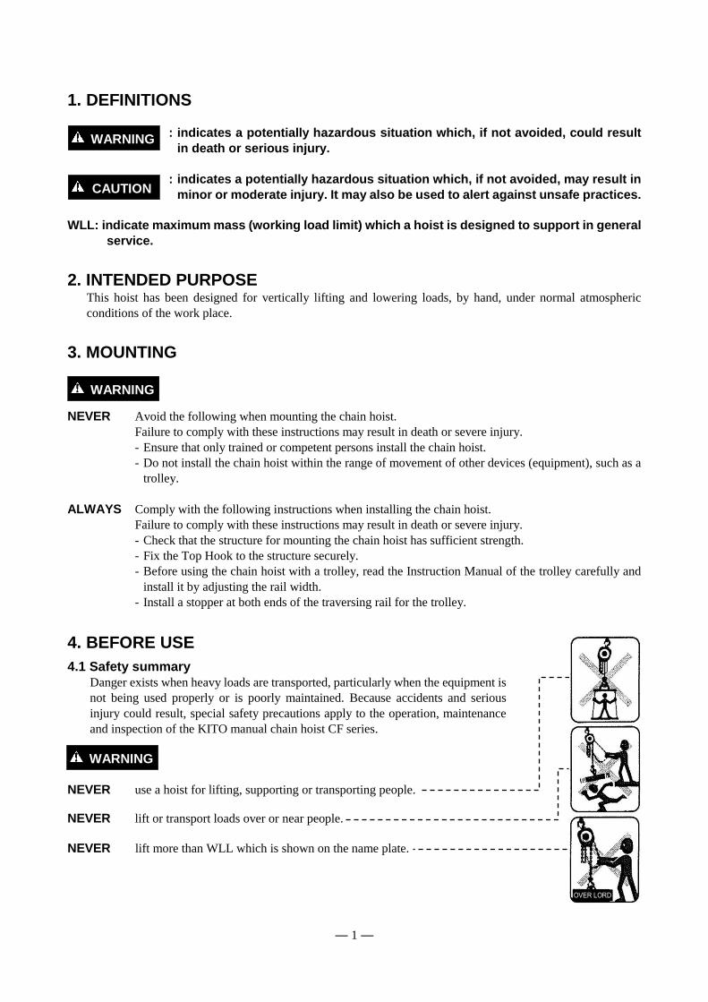
1. DEFINITIONS
: indicates a potentially hazardous situation which, if not avoided, could result
in death or serious injury.
: indicates a potentially hazardous situation which, if not avoided, may result in
minor or moderate injury. It may also be used to alert against unsafe practices.
WLL: indicate maximum mass (working load limit) which a hoist is designed to support in general
service.
2. INTENDED PURPOSE This hoist has been designed for vertically lifting and lowering loads, by hand, under normal atmospheric
conditions of the work place.
3. MOUNTING
NEVER Avoid the following when mounting the chain hoist.
Failure to comply with these instructions may result in death or severe injury.
- Ensure that only trained or competent persons install the chain hoist.
- Do not install the chain hoist within the range of movement of other devices (equipment), such as a
trolley.
ALWAYS Comply with the following instructions when installing the chain hoist.
Failure to comply with these instructions may result in death or severe injury.
- Check that the structure for mounting the chain hoist has sufficient strength.
- Fix the Top Hook to the structure securely.
- Before using the chain hoist with a trolley, read the Instruction Manual of the trolley carefully and
install it by adjusting the rail width.
- Install a stopper at both ends of the traversing rail for the trolley.
4. BEFORE USE
4.1 Safety summary
Danger exists when heavy loads are transported, particularly when the equipment is
not being used properly or is poorly maintained. Because accidents and serious
injury could result, special safety precautions apply to the operation, maintenance
and inspection of the KITO manual chain hoist CF series.
NEVER use a hoist for lifting, supporting or transporting people. NEVER lift or transport loads over or near people.
NEVER lift more than WLL which is shown on the name plate.
WARNING
WARNING
WARNING
CAUTION

— 2 —
ALWAYS let people around you know when a lift is about to begin.
ALWAYS read the operation and safety instructions.
Remember proper rigging and lifting techniques are the responsibility of the operator. Check
all applicable safety codes, regulations and other applicable laws for further information
about the safe use of your hoist.
More detailed safety information is contained in the following pages. For additional
information, please contact KITO Corporation or your authorized KITO dealer.
4.2 Safety instructions
4.2.1 Before use
ALWAYS allow the instructed (trained in safety and operation) people to operate the hoist. ALWAYS check the hoist before daily use according to the “Daily inspection” (Refer to
7.2). ALWAYS make sure that the chain length is long enough for the intended job. ALWAYS check that the hook latches work properly and replace missing or broken hook
latches (Refer to 7.3). ALWAYS check the brake (Refer to 7.3). ALWAYS oil the load chain regularly (Refer to 8.1.2).
ALWAYS use two hoists which each has WLL equal to or more than the load to be lifted
whenever you must use two hoists to lift a load. This will provide adequate
protection in the event that a sudden load shift or failure of one hoist occurs. NEVER use a hoist without a hoist name plate. NEVER use modified or deformed hooks. NEVER use non-authentic chains on the hoist.
4.2.2 While operation
ALWAYS make sure that the load is properly seated in the hook. ALWAYS tighten the slack out of the chain and sling when starting a lift to prevent a
sudden loading.
NEVER operate a hoist unless the load is centered under the hoist. NEVER use the hoist chain as a sling.
WARNING
ALWAYS read safety instructions

— 3 —
NEVER use a twisted, kinked, damaged or stretched load chain. NEVER swing a suspended load. NEVER support a load on the tip of the hook. NEVER contact the load chain over an edge. NEVER weld or cut a load suspended by a hoist. NEVER use the hoist chain as a welding electrode. NEVER operate a hoist so far that the bottom hook touches the hoist body. NEVER operate a hoist so far that the load chain pulls the anchorage.
NEVER operate a hoist if excessive noise occurs. NEVER use the capsized load chain.
4.2.3 After operation
ALWAYS set the load down safely after carrying.
NEVER suspend a load for an extended period of time.
NEVER leave a suspended load unattended.
NEVER throw a hoist.
4.2.4 Maintenance ALWAYS let the qualified service personnel inspect the hoist periodically (Refer to 7.3).
NEVER splice, add and weld a load chain for extension.
4.2.5 Others ALWAYS consult the manufacturer or your dealer if you plan to use a hoist in an
excessively corrosive environment (salt water, sea air and/or acid, explosive
environment or other corrosive compounds, etc.).
NEVER use a hoist which has been taken out of service until the hoist has been properly
repaired or replaced. NEVER remove or obscure the warning tags and labels.
Warning tags are installed on a hand chain.
— 4 —
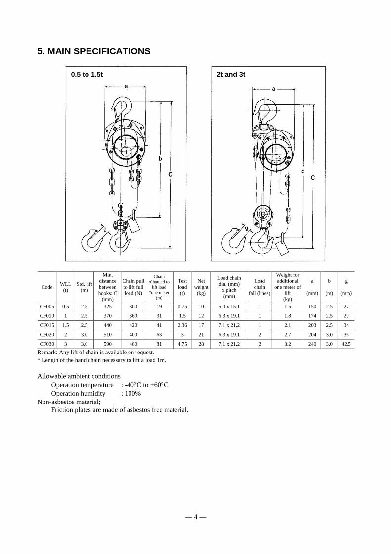
5. MAIN SPECIFICATIONS
Code WLL
(t) Std. lift
(m)
Min. distance
between
hooks: C (mm)
Chain pull
to lift full
load (N)
Chain
o’hauled to
lift load
*one meter
(m)
Test
load
(t)
Net
weight
(kg)
Load chain
dia. (mm) x pitch
(mm)
Load
chain
fall (lines)
Weight for additional
one meter of
lift (kg)
a
(mm)
b
(m)
g
(mm)
CF005 0.5 2.5 325 300 19 0.75 10 5.0 x 15.1 1 1.5 150 2.5 27
CF010 1 2.5 370 360 31 1.5 12 6.3 x 19.1 1 1.8 174 2.5 29
CF015 1.5 2.5 440 420 41 2.36 17 7.1 x 21.2 1 2.1 203 2.5 34
CF020 2 3.0 510 400 63 3 21 6.3 x 19.1 2 2.7 204 3.0 36
CF030 3 3.0 590 460 81 4.75 28 7.1 x 21.2 2 3.2 240 3.0 42.5
Remark: Any lift of chain is available on request.
* Length of the hand chain necessary to lift a load 1m.
Allowable ambient conditions
Operation temperature : -40C to +60C
Operation humidity : 100%
Non-asbestos material;
Friction plates are made of asbestos free material.
0.5 to 1.5t 2t and 3t
— 5 —
6. OPERATION
6.1 Intended purpose of hoist operation
This hoist has been designed for vertically lifting and lowering loads, by hand, under normal atmospheric conditions
of the work place.
However, since dealing with heavy loads may involve unexpected danger, all the “Safety instructions” (Refer to
3.2) must be followed.
6.2 Safety working environment
The operator must be aware of the following points while using the hoist.
(1) The operator must have a clear and unobstructed view of the entire travel area before operating the hoist. When
not possible, a second or more persons must serve as scouts in the nearby area.
(2) The operator must check the entire travel area is safe and secure before operating the hoist.
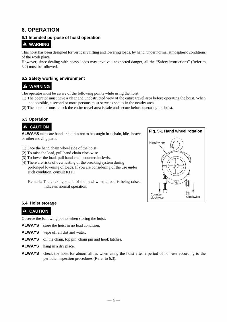
6.3 Operation
ALWAYS take care hand or clothes not to be caught in a chain, idle sheave
or other moving parts.
(1) Face the hand chain wheel side of the hoist.
(2) To raise the load, pull hand chain clockwise.
(3) To lower the load, pull hand chain counterclockwise.
(4) There are risks of overheating of the breaking system during
prolonged lowering of loads. If you are considering of the use under
such condition, consult KITO.
Remark: The clicking sound of the pawl when a load is being raised
indicates normal operation.
6.4 Hoist storage
Observe the following points when storing the hoist.
ALWAYS store the hoist in no load condition.
ALWAYS wipe off all dirt and water.
ALWAYS oil the chain, top pin, chain pin and hook latches.
ALWAYS hang in a dry place.
ALWAYS check the hoist for abnormalities when using the hoist after a period of non-use according to the
periodic inspection procedures (Refer to 6.3).
WARNING
WARNING
CAUTION
Fig. 5-1 Hand wheel rotation
Hand wheel
Counter- clockwise
Clockwise
CAUTION
— 6 —
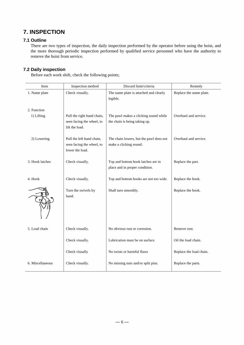
7. INSPECTION
7.1 Outline
There are two types of inspection, the daily inspection performed by the operator before using the hoist, and
the more thorough periodic inspection performed by qualified service personnel who have the authority to
remove the hoist from service.
7.2 Daily inspection
Before each work shift, check the following points;
Item Inspection method Discard limit/criteria Remedy
1. Name plate Check visually. The name plate is attached and clearly
legible.
Replace the name plate.
2. Function
1) Lifting Pull the right hand chain,
seen facing the wheel, to
lift the load.
The pawl makes a clicking sound while
the chain is being taking up.
Overhaul and service.
2) Lowering Pull the left hand chain,
seen facing the wheel, to
lower the load.
The chain lowers, but the pawl does not
make a clicking sound.
Overhaul and service.
3. Hook latches Check visually. Top and bottom hook latches are in
place and in proper condition.
Replace the part.
4. Hook Check visually. Top and bottom hooks are not too wide.
Replace the hook.
Turn the swivels by
hand.
Shall turn smoothly. Replace the hook.
5. Load chain Check visually. No obvious rust or corrosion.
Remove rust.
Check visually. Lubrication must be on surface.
Oil the load chain.
Check visually No twists or harmful flaws
Replace the load chain.
6. Miscellaneous Check visually. No missing nuts and/or split pins.
Replace the parts.
— 7 —
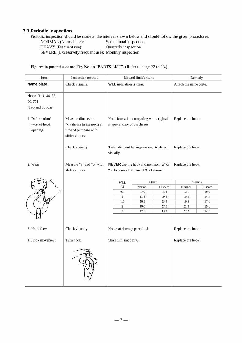
7.3 Periodic inspection
Periodic inspection should be made at the interval shown below and should follow the given procedures.
NORMAL (Normal use): Semiannual inspection
HEAVY (Frequent use): Quarterly inspection
SEVERE (Excessively frequent use): Monthly inspection
Figures in parentheses are Fig. No. in “PARTS LIST”. (Refer to page 22 to 23.)
Item Inspection method Discard limit/criteria Remedy
Name plate
Check visually. WLL indication is clear. Attach the name plate.
Hook [1, 4, 44, 56,
66, 75]
(Top and bottom)
1. Deformation/
twist of hook
opening
Measure dimension
“c”(shown in the next) at
time of purchase with
slide calipers.
No deformation comparing with original
shape (at time of purchase)
Replace the hook.
Check visually. Twist shall not be large enough to detect
visually.
Replace the hook.
2. Wear Measure “a” and “b” with
slide calipers.
NEVER use the hook if dimension “a” or
“b” becomes less than 90% of normal.
Replace the hook.
3. Hook flaw Check visually. No great damage permitted.
Replace the hook.
4. Hook movement Turn hook.
Shall turn smoothly.
Replace the hook.
WLL
(t)
a (mm) b (mm)
Normal Discard Normal Discard
0.5 17.0 15.3 12.1 10.9
1 21.8 19.6 16.0 14.4
1.5 26.5 23.9 19.5 17.6
2 30.0 27.0 21.8 19.6
3 37.5 33.8 27.2 24.5

— 8 —
Item Inspection method Discard limit/criteria Remedy
5. Top/bottom fixture
damage
[fittings of 1, 4, 44,
56, 66, 75]
Check visually. No slack or missing rivets, nuts or bolts Replace the hook.
6. Idle sheave rotation
[55, 61 70]
Hold the load chain with
both hands and turn the
idle sheave by moving
the chain up and down.
Smooth rotation Overhaul.
7. Hook latch
[2, 6, 45, 57, 67, 76]
Check visually. Proper positioning and smooth working Replace the hook latch or
hook.
Load chain [42]
1. Wear Measure with slide
calipers.
Measure the sum of pitches of five chain
links and check that the maximum length
does not exceed the value shown in table
below.
Replace the chain.
2. Rust, flaw,
deformation
Check visually. No obvious rust (Apply oil as necessary.) Remove rust.
No twist or harmful flaw.
Replace the load chain.
Hook yoke
(Top set [1, 44, 66])
(Bottom set [4, 56, 75])
Joint of top/bottom
fittings with top pin
[3] and chain pin [7,
46]
Measure hole diameter of
joint area in two
directions at right angle.
Deformation not permitted (if each
measured value differs more than
0.5mm).
Replace the part.
Function
1. Lifting and
lowering
Lift and lower a light
load.
No abnormal difficulty in lifting or
lowering
Overhaul and service.
One pitch
Sum of pitches of five
links
WLL
(t)
Sum of pitches of five
links (mm)
Discard limit
(mm)
0.5 75.5 77.7
1, 2 95.5 98.3
1.5, 3 106.0 109.1
— 9 —
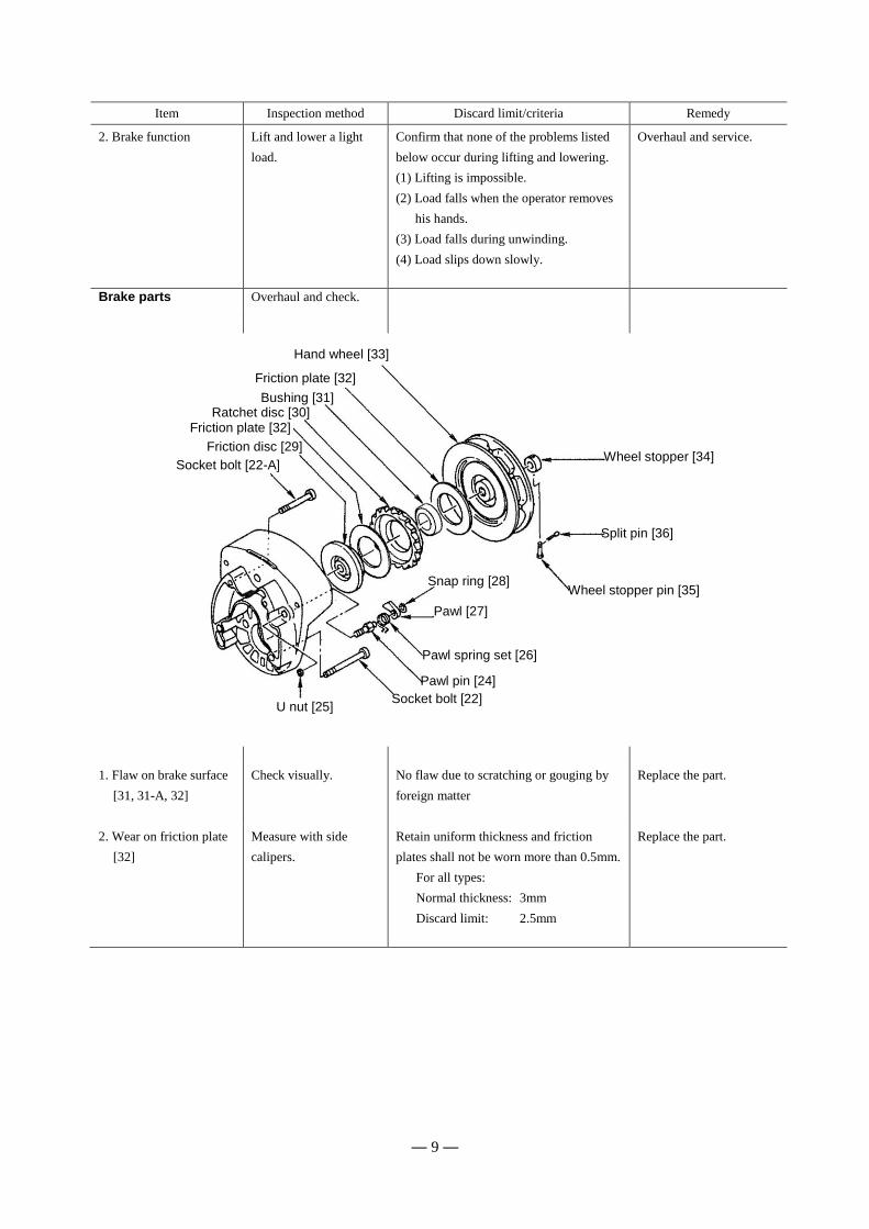
Item Inspection method Discard limit/criteria Remedy
2. Brake function Lift and lower a light
load.
Confirm that none of the problems listed
below occur during lifting and lowering.
(1) Lifting is impossible.
(2) Load falls when the operator removes
his hands.
(3) Load falls during unwinding.
(4) Load slips down slowly.
Overhaul and service.
Brake parts Overhaul and check.
1. Flaw on brake surface
[31, 31-A, 32]
Check visually. No flaw due to scratching or gouging by
foreign matter
Replace the part.
2. Wear on friction plate
[32]
Measure with side
calipers.
Retain uniform thickness and friction
plates shall not be worn more than 0.5mm.
For all types:
Normal thickness: 3mm
Discard limit: 2.5mm
Replace the part.
Hand wheel [33]
Wheel stopper [34]
Split pin [36]
Snap ring [28] Wheel stopper pin [35]
U nut [25]
Pawl spring set [26]
Pawl pin [24]
Pawl [27]
Friction plate [32]
Bushing [31] Ratchet disc [30]
Friction plate [32]
Friction disc [29]
Socket bolt [22-A]
Socket bolt [22]
— 10 —
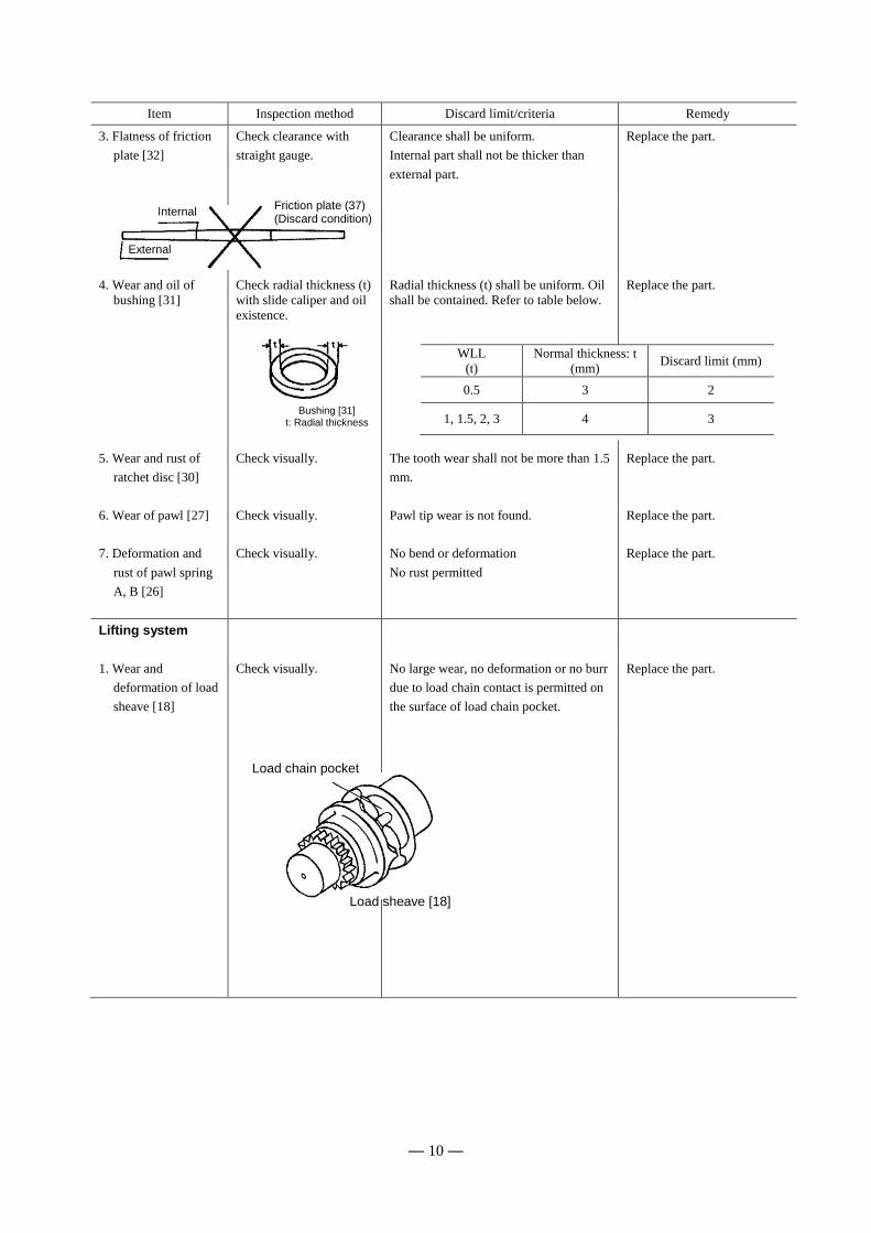
Item Inspection method Discard limit/criteria Remedy
3. Flatness of friction
plate [32]
Check clearance with
straight gauge.
Clearance shall be uniform.
Internal part shall not be thicker than
external part.
Replace the part.
4. Wear and oil of
bushing [31]
Check radial thickness (t)
with slide caliper and oil
existence.
Radial thickness (t) shall be uniform. Oil
shall be contained. Refer to table below.
Replace the part.
5. Wear and rust of
ratchet disc [30]
Check visually. The tooth wear shall not be more than 1.5
mm.
Replace the part.
6. Wear of pawl [27] Check visually. Pawl tip wear is not found.
Replace the part.
7. Deformation and
rust of pawl spring
A, B [26]
Check visually. No bend or deformation
No rust permitted
Replace the part.
Lifting system
1. Wear and
deformation of load
sheave [18]
Check visually. No large wear, no deformation or no burr
due to load chain contact is permitted on
the surface of load chain pocket.
Replace the part.
Friction plate (37) (Discard condition)
Internal
External
Bushing [31] t: Radial thickness
Load chain pocket
Load sheave [18]
WLL
(t)
Normal thickness: t
(mm) Discard limit (mm)
0.5 3 2
1, 1.5, 2, 3 4 3
— 11 —
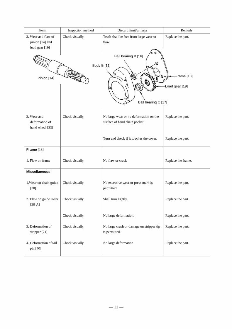
Item Inspection method Discard limit/criteria Remedy
2. Wear and flaw of
pinion [14] and
load gear [19]
Check visually. Teeth shall be free from large wear or
flaw.
Replace the part.
3. Wear and
deformation of
hand wheel [33]
Check visually. No large wear or no deformation on the
surface of hand chain pocket
Replace the part.
Turn and check if it touches the cover.
Replace the part.
Frame [13]
1. Flaw on frame
Check visually.
No flaw or crack
Replace the frame.
Miscellaneous
1.Wear on chain guide
[20]
Check visually. No excessive wear or press mark is
permitted.
Replace the part.
2. Flaw on guide roller
[20-A]
Check visually. Shall turn lightly. Replace the part.
Check visually. No large deformation.
Replace the part.
3. Deformation of
stripper [21]
4. Deformation of tail
pin [40]
Check visually.
Check visually.
No large crush or damage on stripper tip
is permitted.
No large deformation
Replace the part.
Replace the part.
Pinion [14] Frame [13]
Ball bearing C [17]
Load gear [19]
Ball bearing B [16]
Body B [11]
— 12 —
8. MAINTENANCE
(1) NEVER perform maintenance on the hoist while it is supporting a load.
(2) Before performing maintenance, attach the tag;
[“DANGER”: NEVER OPERATE EQUIPMENT BEING REPAIRED.]
(3) Only allow qualified service personnel to perform maintenance.
(4) After performing any maintenance on the hoist, ALWAYS test to WLL before returning to service.
ALWAYS take care hand or clothes not to be caught in a chain, idle sheave or other moving parts.
8.1 Lubrication 8.1.1 Applying grease to gear
Remove body B (11) in the way of “8.2 Overhaul” (Refer to page 13 and 14).
Remove old grease and replace with new grease (standard grease(1)), at annual inspection.
Temperature range of standard grease is -40C to +60C.
If the hoist is used at temperature below -40C or above +60C, consult the manufacturer or dealer since some
parts shall be changed.
Note: (1) Calcium soap grease equivalent of NLGI (National Lubricating Grease Institute)/#2
8.1.2 Load chain
Failure to maintain clean and well lubricated load chain will void the manufacturer’s warranty.
ALWAYS lubricate load chain weekly, or more frequently, depending on severity of service.
ALWAYS lubricate more frequently than normal in a corrosive environment.(2)
ALWAYS use machine oil equivalent to ISO VG46 or 68.
Note: (2) KITO has a corrosion-resistant chain as an option. For information of KITO’s regular and
corrosion-resistant chain, please ask your dealer.
WARNING
CAUTION
WARNING

— 13 —
8.2 Overhaul, assembly and adjustment 8.2.1 Overhaul
Figures in parentheses are Fig. No. in “PARTS LIST”. (Refer to page 22 and 23.)
Overhaul procedures Remarks
1. Put a hoist with wheel cover side up.
2. Unscrew three nuts [38] (with the spring washers [39]) fixing the wheel
cover [37].
3. Remove the wheel cover [37] from the body A [10].
4. Insert the standing link of the hand chain [43] into the notch of the hand
wheel [33] and remove the hand chain by turning the hand wheel
counterclockwise.
Bring the notch of the hand
wheel to the right hand.
5. Pull out the split pin [36] from the wheel stopper pin [35] and remove the
wheel stopper pin and the wheel stopper [34] from the pinion [14].
6. Remove the hand wheel [33] from the pinion [14] by turning the hand wheel
counterclockwise.
If the hand wheel is too tight to
turn by hand, put the hand
chain on the hand wheel back
again and pull it down hard. It
will release the brake.
7. Remove two friction plates [32], the ratchet disc [30] and the bushing [31]
from the friction disc [29].
8. Remove the friction disk [29] from the pinion [14] by turning
counterclockwise holding the end of the pinion with fingers.
9. Remove the snap ring [28] from the pawl pin [24] (on the side plate A [10])
and then remove the pawl [27] and pawl spring set [26].
10. Unscrew the pawl pin [24]. The pawl pin is fixed with the
U nut [25].
11. Unscrew four socket bolts [22, 22-A] connecting body A [10] and B [11]. Four socket bolts are fixed
with U nuts [23] on the body B
side.
12. Separate the body A [10] and B [11].
13. Take ball bearing A [15] and C [17-A] out of the body A [10]. Remove the bearing by tapping
the ball bearing A and C with a
wooden hammer from the
brake side.
14. Remove top hook [1] and top pin [3] from the body B [11].
— 14 —
Overhaul procedures Remarks
15. Remove pinion [14], chain guide [20] (or guide rollers [20-A]), stripper
[21], tail pin [40], and load chain [42].
16. Remove the frame [13].
17. Take load sheave [18] out of the load gear [19].
18. Remove the load gear [19].
19. Unscrew tap socket bolt [41] from the body B [11].
20. Pull the split pin [9] out of the slotted nut [8] and remove the slotted nut and
chain pin [7] from the bottom hook [4].
8.2.2 Assembly and adjustment
Assembly procedures Remarks
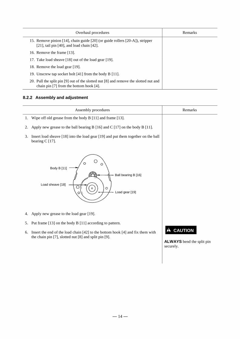
1. Wipe off old grease from the body B [11] and frame [13].
2. Apply new grease to the ball bearing B [16] and C [17] on the body B [11].
3. Insert load sheave [18] into the load gear [19] and put them together on the ball
bearing C [17].
4. Apply new grease to the load gear [19].
5. Put frame [13] on the body B [11] according to pattern.
6. Insert the end of the load chain [42] to the bottom hook [4] and fix them with
the chain pin [7], slotted nut [8] and split pin [9].
ALWAYS bend the split pin
securely.
Body B [11]
Ball bearing B [16]
Load gear [19]
Load sheave [18]
CAUTION

— 15 —
Assembly procedures Remarks
7. Wind load chain [42] round the load sheave [18] so that the bottom hook side
comes to right hand and the end link of the other side becomes standing to the
load sheave pocket.
Put the welded part of the
standing chain link outward.
8. Put chain guide [20] (or guide rollers for 0.5t [20-A]) on the frame [13].
9. Put stripper [21] on the frame [13].
10. Insert pinion [14] shaft from its gear side into the frame [13].
11. Insert top pin [3] into the frame [13] and put top hook [1] to the top pin.
Fit the larger boss of chain
guide [20] into holes on frame
[13].
Load chain [42]
Slotted nut [8]
Chain pin [7]
Split pin [9]
Bottom hook [4]
CAUTION
Body B [11]
Welded part of standing link
Load chain [42]
To bottom hook No load side
Frame [13]
Load sheave [18]
— 16 —
Assembly procedures Remarks
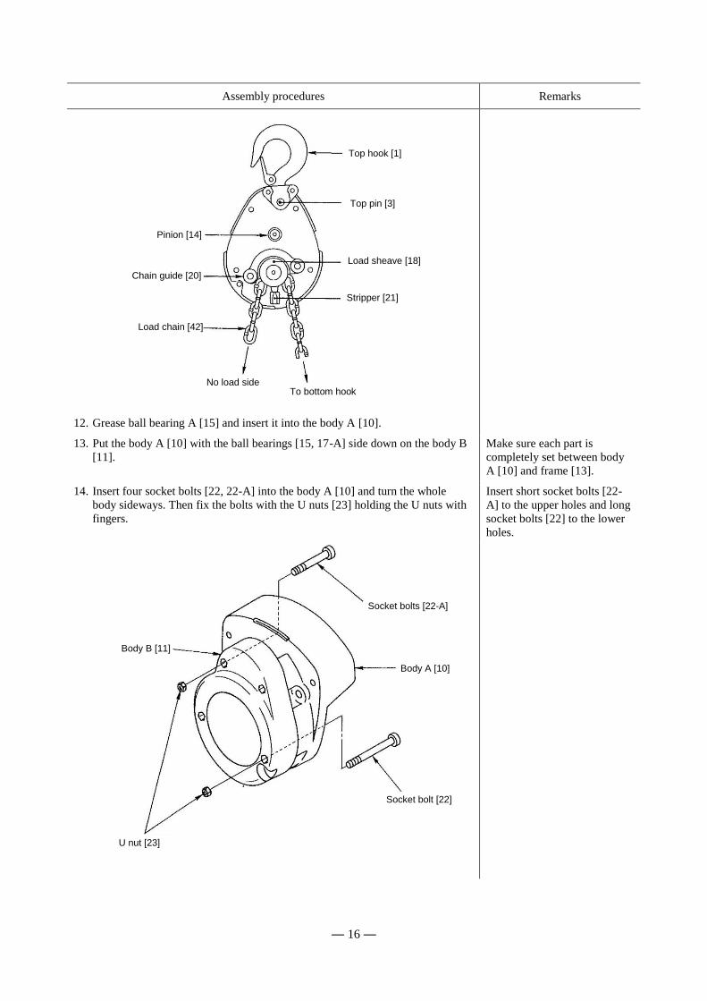
12. Grease ball bearing A [15] and insert it into the body A [10].
13. Put the body A [10] with the ball bearings [15, 17-A] side down on the body B
[11].
Make sure each part is
completely set between body
A [10] and frame [13].
14. Insert four socket bolts [22, 22-A] into the body A [10] and turn the whole
body sideways. Then fix the bolts with the U nuts [23] holding the U nuts with
fingers.
Insert short socket bolts [22-
A] to the upper holes and long
socket bolts [22] to the lower
holes.
Top hook [1]
Top pin [3]
Load sheave [18]
Stripper [21]
No load side
Chain guide [20]
Pinion [14]
Socket bolts [22-A]
Socket bolt [22]
Body A [10]
U nut [23]
Load chain [42]
To bottom hook
Body B [11]
— 17 —
Assembly procedures Remarks
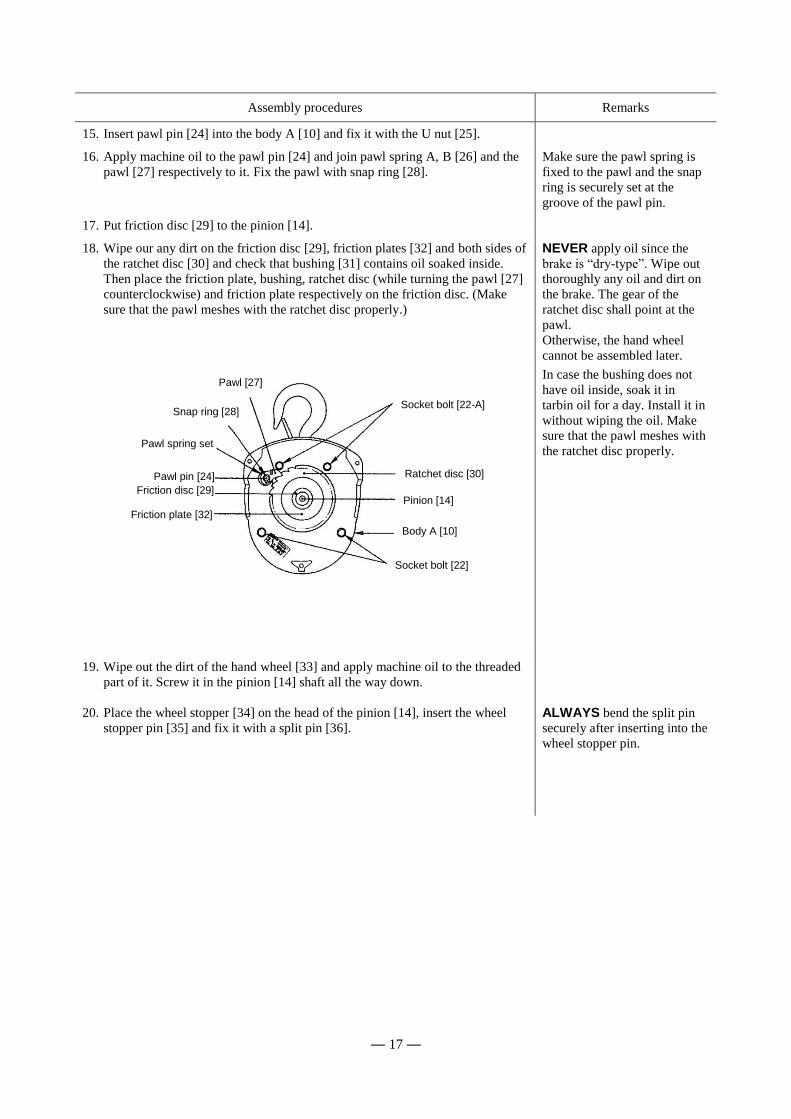
15. Insert pawl pin [24] into the body A [10] and fix it with the U nut [25].
16. Apply machine oil to the pawl pin [24] and join pawl spring A, B [26] and the
pawl [27] respectively to it. Fix the pawl with snap ring [28].
Make sure the pawl spring is
fixed to the pawl and the snap
ring is securely set at the
groove of the pawl pin.
17. Put friction disc [29] to the pinion [14].
18. Wipe our any dirt on the friction disc [29], friction plates [32] and both sides of
the ratchet disc [30] and check that bushing [31] contains oil soaked inside.
Then place the friction plate, bushing, ratchet disc (while turning the pawl [27]
counterclockwise) and friction plate respectively on the friction disc. (Make
sure that the pawl meshes with the ratchet disc properly.)
NEVER apply oil since the
brake is “dry-type”. Wipe out
thoroughly any oil and dirt on
the brake. The gear of the
ratchet disc shall point at the
pawl.
Otherwise, the hand wheel
cannot be assembled later.
In case the bushing does not
have oil inside, soak it in
tarbin oil for a day. Install it in
without wiping the oil. Make
sure that the pawl meshes with
the ratchet disc properly.
19. Wipe out the dirt of the hand wheel [33] and apply machine oil to the threaded
part of it. Screw it in the pinion [14] shaft all the way down.
20. Place the wheel stopper [34] on the head of the pinion [14], insert the wheel
stopper pin [35] and fix it with a split pin [36].
ALWAYS bend the split pin
securely after inserting into the
wheel stopper pin.
Socket bolt [22-A]
Ratchet disc [30]
Pinion [14]
Pawl [27]
Snap ring [28]
Pawl spring set
Pawl pin [24]
Friction disc [29]
Friction plate [32]
Body A [10]
Socket bolt [22]
— 18 —
Assembly procedures Remarks
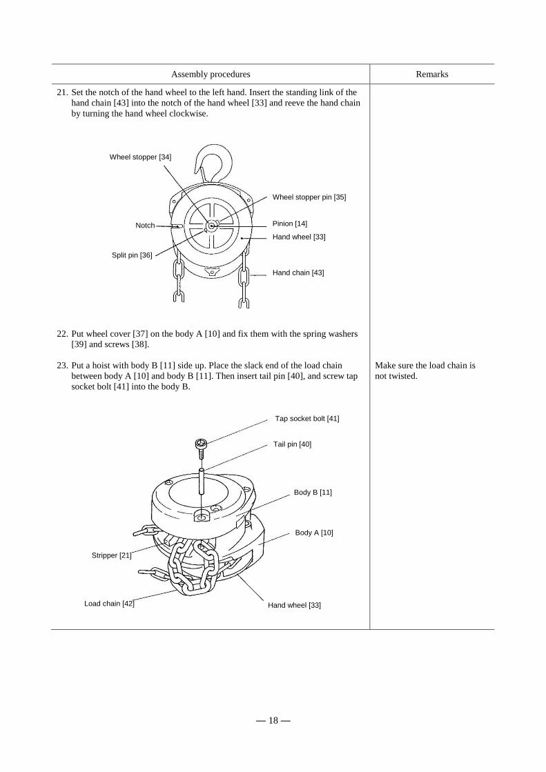
21. Set the notch of the hand wheel to the left hand. Insert the standing link of the
hand chain [43] into the notch of the hand wheel [33] and reeve the hand chain
by turning the hand wheel clockwise.
22. Put wheel cover [37] on the body A [10] and fix them with the spring washers
[39] and screws [38].
23. Put a hoist with body B [11] side up. Place the slack end of the load chain
between body A [10] and body B [11]. Then insert tail pin [40], and screw tap
socket bolt [41] into the body B.
Make sure the load chain is
not twisted.
Wheel stopper pin [35]
Notch
Wheel stopper [34]
Split pin [36]
Pinion [14]
Hand wheel [33]
Hand chain [43]
Tap socket bolt [41]
Tail pin [40]
Body B [11]
Body A [10]
Hand wheel [33] Load chain [42]
Stripper [21]

— 19 —
9. TROUBLESHOOTING
Situation Cause Explanation Remedy
The pawl makes the
proper clicking sound
but fails to lift the
load.
Worn friction plates When used at high frequency without
performing maintenance regularly, the
friction plates will wear down. This will
create gaps between the friction disc,
bushing and hand wheel, and cause the
brake to slip.
Disassemble and
replace the friction
plates and bushing.
The pawl produces
absolutely no sound
and fails to lift the
load.
The pawl has been
improperly
assembled.
If the pawl is assembled facing the other
way, or otherwise assembled incorrectly,
it will not cleanly mesh with the ratchet
disc.
Disassemble and then
reassemble parts
correctly.
The pawl is not
moving smoothly.
Unless maintenance is performed
regularly, dirt will adhere to the grease on
the pawl and pawl shaft. Movement will
become sluggish and the pawl will remain
stuck in the kicked out position.
Same as above
The chain is tight
when lifting, even
without a load. (A
squeaking noise can
be heard at times.)
Worn load gear
teeth
Unless maintenance is performed
regularly, greased parts will dry, resulting
in wear and damage, and improper
meshing of gears.
Disassemble and
replace the pinion, load
gear, body B, frame
and ball bearing. Worn or damaged
bearing.
Improper lowering or
the chain is
extremely tight when
lowering.
The brake is too
tight.
Due to shock during work, or because the
load was left suspended for a long period
of time, the brake tightened.
Free the brake forcibly
by jerking the hand
chain.
The brake is rusted. Unless maintenance is performed
regularly, rusting will occur.
Disassemble and
replace parts where
necessary.
The hoist drops the
load the instant
lowering is started.
The braking surface
is dirty.
During assembly, the braking surface
must be wiped cleaned of dirt.
Disassemble and then
reassemble parts
correctly.
The braking surface
is oily.
The braking surface must not be allowed
to become soiled with grease or machine
oil because it is a dry-type brake.
Disassemble and then
reassemble parts. Do
not oil or grease the
braking surface or
friction plates.
Load slipping The braking surface
is oily.
Same as above Same as above
The braking surface
is dirty.
During assembly, the braking surface
must be wiped cleaned of dirt.
Disassemble and then
reassemble parts
correctly.
— 20 —
10. WARRANTY
KITO Corporation (“KITO”) extends the following warranty to the original purchaser (“Purchaser”) of new
products manufactured by “KITO” (KITO’s Products).
(1) KITO warrants that KITO’s Products, when shipped, shall be free from defects in workmanship and/or
materials under normal use and service and “KITO” shall, at the election of “KITO”, repair or replace free
of charge any parts or items which are proven to have said defects, provided that all claims for defects
under this warranty shall be made in writing immediately upon discovery and, in any event, within one (1)
year from the date of purchase of KITO’s Products by “Purchaser” and provided, further, that defective
parts or items shall be kept for examination by “KITO“ or its authorized agents or returned to KITO’s
factory or authorized service center upon request by “KITO”.
(2) KITO does not warrant components of products provided by other manufacturers. However to the extent
possible, “KITO” will assign to “Purchaser” applicable warranties of such other manufacturers.
(3) Except for the repair or replacement mentioned in (1) above which is “KITO”’s sole liability and
purchaser’s exclusive remedy under this warranty. “KITO” shall not be responsible for any other claims
arising out of the purchase and use of KITO’s Products, regardless of whether “Purchacer”’s claims are
based on breach of contract, tort or other theories, including claims for any damages whether direct,
indirect, incidental or consequential.
(4) This warranty is conditional upon the installation, maintenance and use of KITO’s Products pursuant to the
product manuals prepared in accordance with content instructions by “KITO”. This warranty shall not
apply to KITO’s Products which have been subject to negligence, misuse, abuse, misapplication or any
improper use or combination or improper fittings, alignment or maintenance.
(5) “KITO” shall not be responsible for any loss or damage caused by transportation, prolonged or improper
storage or normal wear and tear of KITO’s Products or for loss of operating time.
(6) This warranty shall not apply to KITO’s products which have been fitted with or repaired with parts,
components or items not supplied or approved by “KITO” or which have been modified or altered.
THIS WARRANTY IS IN LIEU OF ALL OTHER WARRANTIES, EXPRESS OR IMPLIED, INCLUDING
BUT NOT LIMITTED TO ANY WARRANTY OF MERCHANTABILITY OR OF FITNESS FOR A
PARTICULAR PURPOSE.
— 21 —
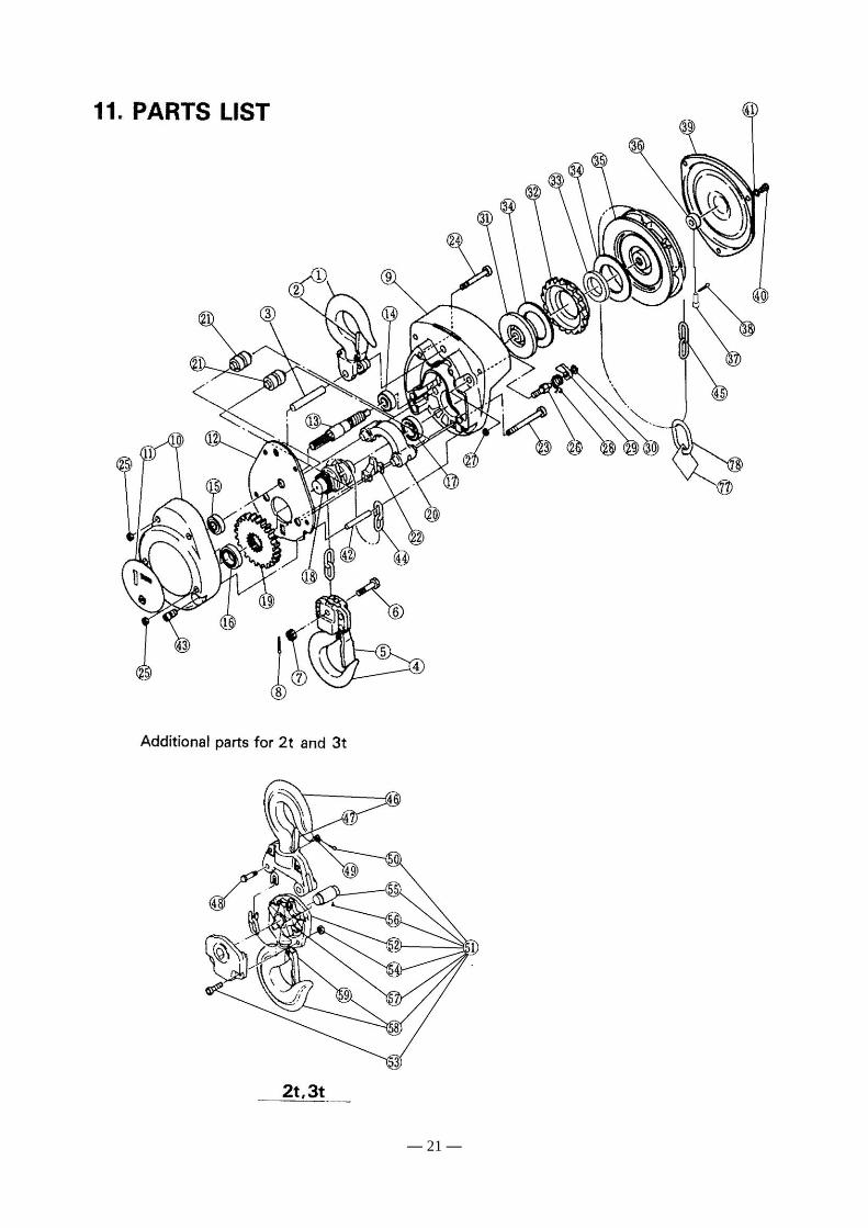
11. PARTS LIST

— 22 —
CONTENTS OF EC DECLARATION OF CONFORMITY
We, KITO Corporation, 2000, Tsuijiarai, Showa-cho, Nakakoma-gun, Yamanashi, 409-3853, Japan declare under our sole responsibility that the products:
Hand chain operated chain hoist CF, model CF4
in capacity range of 500 kg up to 3 tonnes,
to which this declaration relates is in conformity with the following EC directives and standards. EC directives: Machinery Directive 2006/42/EC
Harmonized standards:
EN ISO 12100: 2010 Risk assessment and risk reduction
EN 818-7: 2002 +A1: 2008 Short link chain for lifting purposes, increased quality, grade V, certified by Fachausschuss Metall und Oberflächenbehandlung
EN 13157: 2004 +A1: 2009 Hand powered cranes Authorized representative for the arrangement of the technical documents: Udo Kleinevoß
Technical Manager
Kito Europe GmbH. 40549 Düsseldorf
D/C CF-1207-E-02-OM
A08-02-OM


URL. http://kito.com/
KITO Europe GmbH Heerdter Lohweg 93, D-40549 Düsseldorf, Germany TEL: +49-(0)211-528009-00 FAX: +49-(0)211-528009-59 E-mail: [email protected] URL: http://www.kito.net/
KITO corporation Tokyo Head office: SHINJUKU NS Building 9F, 2-4-1, Nishi-Shinjuku, Shinjuku-ku, Tokyo 163-0809, Japan
Head office & Factory: 2000 Tsuijiarai Showa-Cho, Nakakoma-Gun, Yamanashi 409-3853, Japan
URL: http://kito.com/


![End Carriage, Geared Motor, Peripheral Equipment KITO CRANE€¦ · KITO CRANE APPLICATIONS [Overhead cranes] CRANE TEST EQUIPMENT At KITO, cranes are tested for durability and reliability](https://static.fdocuments.in/doc/165x107/5fda19473e720a0b885d42fe/end-carriage-geared-motor-peripheral-equipment-kito-crane-kito-crane-applications.jpg)


