
Overview of Physics Results from MAST towards ITER/DEMO ...13)65.pdf · Overview of Physics Results...
35
H. Meyer, I.G. Abel, R.J. Akers, A. Allan, S.Y. Allan, L.C. Appel, O. Asunta, et.al CCFE-PR(13)65 Overview of Physics Results from MAST towards ITER/DEMO and the MAST Upgrade
-
Upload
hoangquynh -
Category
Documents
-
view
219 -
download
0
Transcript of Overview of Physics Results from MAST towards ITER/DEMO ...13)65.pdf · Overview of Physics Results...

H. Meyer, I.G. Abel, R.J. Akers, A. Allan, S.Y. Allan,L.C. Appel, O. Asunta, et.al
CCFE-PR(13)65
Overview of Physics Results from MAST towards ITER/DEMO and the
MAST Upgrade

Enquiries about copyright and reproduction should in the first instance be addressed to the Culham Publications Officer, Culham Centre for Fusion Energy (CCFE), Library, Culham Science Centre, Abingdon, Oxfordshire, OX14 3DB, UK. The United Kingdom Atomic Energy Authority is the copyright holder.
Overview of Physics Results from MAST towards ITER/DEMO and the
MAST Upgrade
H. Meyer1, I.G. Abel2, R.J. Akers1, A. Allan3, S.Y. Allan1,L.C. Appel1, O. Asunta4, et.al
1EURATOM/CCFE Fusion Association, Culham Science Centre, OX14 3DB Abingdon (UK)2Rudolf Peierls Centre for Theoretical Physics, University of Oxford, Oxford, UK.
3Department of Physics, University of York, Heslington, York, UK.4Aalto University, Association EURATOM-TEKES, Espoo, Finland.
The following article appeared in Nuclear Fusion, Vol.53, No.10, October 2013, p.104008

.

© 2013 UNITED KINGDOM ATOMIC ENERGY AUTHORITY
The following article appeared in Nuclear Fusion, Vol.53, No.10, October 2013, p.104008 Overview of physics results from MAST towards ITER/DEMO and the MAST Upgrade Meyer H et al This is an author-created, un-copyedited version of an article accepted for publication in Nuclear Fusion. IOP Publishing Ltd and IAEA are not responsible for any errors or omissions in this version of the manuscript or any version derived from it. The Version of Record is available online at doi:10.1088/0029-5515/53/10/104008
Overview of Physics Results from MAST towards
ITER/DEMO and the MAST Upgrade
H. Meyer1, I.G. Abel2, R.J. Akers1, A. Allan3, S.Y. Allan1,
L.C. Appel1, O. Asunta4, M. Barnes2,5, N.C. Barratt3, N. Ben
Ayed1, J.W. Bradley6, J. Canik7, P Cahyna8, M. Cecconello9,
C.D. Challis1, I.T. Chapman1, D. Ciric1, G. Colyer1, N.J.
Conway1, M. Cox1, B.J. Crowley1, S.C. Cowley1, G.
Cunningham1, A. Danilov10, A. Darke1, M.F.M. De Bock11, G.
De Temmerman12, R.O. Dendy1, P. Denner3, D. Dickinson1,
A.Y. Dnestrovsky10, Y. Dnestrovsky10, M.D. Driscoll1, B.
Dudson3, D. Dunai13, M. Dunstan1, P. Dura14, S. Elmore1,6,
A.R. Field1, G. Fishpool1, S. Freethy1, W. Fundamenski1, L.
Garzotti1, Y.C. Ghim1,2, K.J. Gibson3, M.P. Gryaznevich1, J.
Harrison1, E. Havlıckova1, N.C. Hawkes1, W.W. Heidbrink15,
T.C. Hender1, E. Highcock2, D. Higgins14, P. Hill2, B. Hnat14,
M.J. Hole16, J. Horacek8, D.F. Howell1, K. Imada3, O. Jones17,
E. Kaveeva18, D. Keeling1, A. Kirk1, M. Kocan19, R.J. Lake14,
M. Lehnen20, H.J. Leggate21, Y. Liang20, M.K. Lilley22, S.W.
Lisgo23, Y.Q. Liu1, B. Lloyd1, G.P. Maddison1, J. Mailloux1, R.
Martin1, G.J. McArdle1, K.G. McClements1, B. McMillan14, C.
Michael1, F. Militello1, P. Molchanov18, S. Mordijck24, T.
Morgan12, A.W. Morris1, D.G. Muir1, E. Nardon25, V.
Naulin26, G. Naylor1, A.H. Nielsen26, M.R. O’Brien1, T.
O’Gorman3, S. Pamela27, F.I. Parra2,5, A. Patel1, S.D.
Pinches1,23, M.N. Price1, C.M. Roach1, J.R. Robinson14, M.
Romanelli1, V. Rozhansky18, S. Saarelma1, S. Sangaroon8, A.
Saveliev28, R. Scannell1, J. Seidl7, S.E. Sharapov1, A.A.
Schekochihin2, V. Shevchenko1, S. Shibaev1, D. Stork1, J.
Storrs1, A. Sykes1, G.J. Tallents3, P. Tamain25, D. Taylor1, D.
Temple22, N. Thomas-Davies1, A. Thornton1, M.R.
Turnyanskiy1, M. Valovic1, R.G.L. Vann3, E. Verwichte14, P.
Voskoboynikov18, G. Voss1, S.E.V. Warder1, H.R. Wilson3, I.
Wodniak8, S. Zoletnik13, R. Zagorski29 and the MAST and NBI
teams.
1EURATOM/CCFE Fusion Association, Culham Science Centre, Abingdon, UK.
2Rudolf Peierls Centre for Theoretical Physics, University of Oxford, Oxford, UK.

Overview of Physics Results from MAST towards ITER/DEMO and the MAST Upgrade2
3Department of Physics, University of York, Heslington, York, UK.
4Aalto University, Association EURATOM-TEKES, Espoo, Finland.
5MIT Plasma Science and Fusion Center, Cambridge, MA 02139, USA.
6Department of Electrical Engineering and Electronics, University of Liverpool,
Brownlow Hill, Liverpool, UK.
7Oak Ridge National Laboratory, Oak Ridge, TN, USA.
8Institute of Plasma Physics AS CR vvi, Association EURATOM/IPP.CR, Prague,
Czech Republic.
9EURATOM-VR Association, Uppsala University, SE-75120 Uppsala, Sweden.
10Russian Research Centre,Kruchatov Institute, Institute of Nuclear Fusion, Moscow,
Russia.
11Department of Applied Physics, Eindhoven University of Technology, Eindhoven,
The Netherlands.
12DIFFER, Association EURATOM-DIFFER, Nieuwegein, The Netherlands.
13KFKI-RMKI, Association EURATOM, Pf. 49, H-1525 Budapest, Hungary.
14Centre for Fusion, Space and Astrophysics, Department of Physics, Warwick
University, Coventry, UK.
15School of Physical Sciences, University of California, Irvine, CA 92697, USA.
16Plasma Research Laboratory, Research School of Physical Science and Engineering,
Australian National University, Canberra, ACT 0200, Australia.
17Department of Physics, University of Durham, Durham DH1 3LE, UK.
18St Petersburg State Polytechnical University, St Petersburg, Russia.
19Max-Planck-Institut fur Plasmaphysik, EURATOM Association, Garching,
Germany.
20Association EURATOM-FZ Julich, Trilateral Euregio Cluster, D-52425 Julich,
Germany.
21EURATOM/DCU Fusion association, Dublin City University, Glasnevin, Dublin,
Ireland.
22Imperial College of Science, Technology and Medicine, London, UK.
23ITER Organization, CS 90 046, 13067 St Paul lez Durance Cedex, France.
24The College of William and Mary, McGlothlin-Street Hall, Williamsburg, VA
23187, USA.
25CEA-Cadarache, Association Euratom-CEA, 13108 St Paul-lez-Durance, France.
26Association EURATOM/Risø, National Laboratory for Sustainable Energy,
OPL-128, PO Box 49, DK-4000 Roskilde, Denmark.
27IIFS-PIIM Aix Marseille Universite CNRS, 13397 Marseille Cedex20, France.
28A.F. Ioffe Physico-Technical Institute, St Petersburg, Russia.
29Association EURATOM/IPPLM, Institute of Plasma Physics and Laser
Microfusion, Warsaw, Poland.
E-mail: [email protected]
Overview of Physics Results from MAST towards ITER/DEMO and the MAST Upgrade3
Abstract. New diagnostic, modelling and plant capability on the Mega Ampere
Spherical Tokamak (MAST) have delivered important results in key areas for
ITER/DEMO and the upcoming MAST Upgrade, a step towards future ST devices on
the path to fusion currently under procurement. Micro-stability analysis of the pedestal
highlights the potential roles of micro-tearing modes and kinetic ballooning modes for
the pedestal formation. Mitigation of edge localised modes (ELM) using resonant
magnetic perturbation has been demonstrated for toroidal mode numbers n = 3,4,6with an ELM frequency increase by up-to a factor of 9, compatible with pellet fuelling.
The peak heat flux of mitigated and natural ELMs follows the same linear trend with
ELM energy loss and first ELM resolved Ti measurements in the divertor region are
shown. Measurements of flow shear and turbulence dynamics during L-H transitions
show filaments erupting from the plasma edge whilst the full flow shear is still present.
Off-axis neutral beam injection helps to strongly reduce the redistribution of fast-ions
due to fishbone modes when compared to on-axis injection. Low-k ion scale turbulence
has been measured in L-mode and compared to global gyro-kinetic simulations. A
statistical analysis of principal turbulence time scales shows them to be of comparable
magnitude and reasonably correlated with turbulence decorrelation time. Te inside the
island of a neoclassical tearing mode allow the analysis of the island evolution without
assuming specific models for the heat flux. Other results include the discrepancy of the
current profile evolution during the current ramp-up with solutions of the poloidal field
diffusion equation, studies of the anomalous Doppler resonance compressional Alfven
eigenmodes, disruption mitigation studies and modelling of the new divertor design for
MAST Upgrade. The novel 3D electron Bernstein synthetic imaging shows promising
first data sensitive to the edge current profile and flows.
PACS numbers: 52.55.Fa,52.25.Xz,52.35.Ra
Submitted to: Nuclear Fusion
Overview of Physics Results from MAST towards ITER/DEMO and the MAST Upgrade4
1. Introduction
Future magnetic confinement fusion devices face major challenges in the areas of plasma
exhaust, pedestal and ELM physics as well as fast particle and current drive physics.
MAST [1] (A = ε−1 = R/a = 0.85 m/0.65 m∼ 1.3, Ip ≤ 1.5 MA), one of the two leading
spherical tokamaks (ST) in the world (similar to NSTX [2]), is well suited to advance the
physics basis for ITER‡ [3], DEMO or an ST based component test facility (CTF) [4–6]
in these areas [7, 8]. The MAST Upgrade project [9, 10] (under procurement) will
strengthen this even further with the new upper and lower divertor, the off-axis neural
beam heating, the new centre column allowing for a 90% higher flux swing, a 50% higher
toroidal field with 5 times higher I2t and higher shaping capabilities. These substantial
upgrades to the load assembly, the heating system and the power supplies will enable
detailed studies of novel divertor concepts including Super-X [11] and Snow flake [12],
fast particle physics and current drive in a much wider operating space. On MAST the
hot Ti ≤ 3 keV, Te ≤ 2 keV, dense ne = (0.1−1)×1020 m−3 and highly shaped (δ≤ 0.5,
1.6 ≤ κ ≤ 2.5) plasmas are accessed at moderate toroidal field Bt(R = 0.7 m) ≤ 0.62 Tgiving access to regimes at high β = 2µ0 p/B2, strong rotation, where finite Larmor
radius, ρi, and magnetic field curvature effects are enhanced. Apart from this ST unique
parameter regime MAST plasmas also show many similarities to conventional aspect
ratio tokamaks. Research during the last two years has delivered important results for
the ITER physics basis with respect to ELM mitigation (Sec. 5), fast particle physics
(Sec. 6), L-H thresholds (Sec. 5), heat loads (Sec. 5) and NTMs (Sec. 8). Furthermore,
MAST data also helped to resolve critical design issues for the Upgrade such as the
thermal performance of the sliding joint design for the higher toroidal field and longer
pulse length by validating the modelled performance against data from prototype joints,
or testing a controllable high field side mid-plane gas valve (Sec. 9). New radial
field power supplies for the vertical stabilisation control have been incorporated into
the Upgrade scope after extensive testing of the old power supplies on MAST and
analysing the feedback response to ELMs. The increased understanding of the fast
ion redistribution with off-axis NBI (see Sec. 6) suggests that the initially poposed
beam geometry could be improved by angling one of the new beam lines upwards. The
engineering implications of this are currently under investigation.
2. Pedestal and ELMs
The physics determining the width of the edge transport barrier in H-mode and therefore
the width and height of the pedestal is not yet well understood. In recent years a
predictive model for both the height and width of the pedestal has been developed [13],
where the pedestal gradient is limited by kinetic ballooning modes (KBM) and the
growth of the pedestal is ultimately limited by the ideal peeling-ballooning stability
‡ http://www.iter.org
Overview of Physics Results from MAST towards ITER/DEMO and the MAST Upgrade5
0dPe/dψN (kPa)
10
20
30
40
0.9 1.0pe (kPa)
0
0.5
1.0
1.5
2.0
2.5
0.9 1.00
0.1
0.2
0.3
0.40
1
2
3
4
0.295 0.305 0.315time (s)
0.0
0.5
1.0
1.5
2.0
Dalpha Intensity 24459
Individual Profiles
Te (keV)
ne (1019 m
-3)
% of ELM cycle
90%70%50%30%10%
0.0
0.5
1.0
1.5
(a)
pe (kPa)
1.000.980.960.940
10
20
30
(b)
dPe/dψN (kPa)
Combined Profiles
(c)
(d)
(e)
(f)
(g)0.3
0.40
1
(e
0.304s0.308s0.312s
Normalised pol. flux
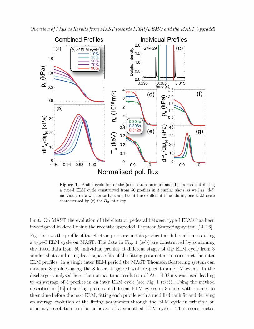
Figure 1. Profile evolution of the (a) electron pressure and (b) its gradient during
a type-I ELM cycle constructed from 50 profiles in 3 similar shots as well as (d-f)
individual data with error bars and fits at three different times during one ELM cycle
characterised by (c) the Dα intensity.
limit. On MAST the evolution of the electron pedestal between type-I ELMs has been
investigated in detail using the recently upgraded Thomson Scattering system [14–16].
Fig. 1 shows the profile of the electron pressure and its gradient at different times during
a type-I ELM cycle on MAST. The data in Fig. 1 (a-b) are constructed by combining
the fitted data from 50 individual profiles at different stages of the ELM cycle from 3
similar shots and using least square fits of the fitting parameters to construct the inter
ELM profiles. In a single inter ELM period the MAST Thomson Scattering system can
measure 8 profiles using the 8 lasers triggered with respect to an ELM event. In the
discharges analysed here the normal time resolution of ∆t = 4.33 ms was used leading
to an average of 3 profiles in an inter ELM cycle (see Fig. 1 (c-e)). Using the method
described in [15] of sorting profiles of different ELM cycles in 3 shots with respect to
their time before the next ELM, fitting each profile with a modified tanh fit and deriving
an average evolution of the fitting parameters through the ELM cycle in principle an
arbitrary resolution can be achieved of a smoothed ELM cycle. The reconstructed
Overview of Physics Results from MAST towards ITER/DEMO and the MAST Upgrade6
average evolution agrees well with the limited number of profiles individual laser pulses
during one ELM cycle [15, 16] as can be seen from Fig. 1 (d-g) showing the measured
profiles with error bars and fits (d-e) as well as the pressure and its gradient (f-g)
calculated form the fits at three times during the ELM cycle (c). It is the pedestal
width that evolves the most, rather than the steepness of the gradient and the region
of steepest gradient moves further inward. With respect to ideal peeling-ballooning
stability this means that the widening of the pedestal region results in a decrease of
the unstable pressure gradient limit [15]. A comparison between the pedestal evolution
at low and high collisionality of the pedestal νped? has been done, although in a non-
dimensionless way. ν? = νei√
mi/(kBTi)ε−3/2qR is the electron ion collision frequency νei
normalised to the ion bounce time (ε = a/R: inverse aspect ratio, q = rBt/RBθ safety
factor). Whilst the evolution of the pedestal pressure in time is similar at high and low
νped? the pedestal width and position evolve more slowly at low ν
ped? . At high ν
ped? only
npede increases at constant T ped
e .
0.0 0.2 0.6 0.8 1.0
Fraction of ELM cycle0.4
kyρ
i
1
2
3
4
5
0.0
0.5
1.0
1.5
γ (v
th,i/a
)MTM
KBM
increasing ∂p/∂r
ψN = 0.96
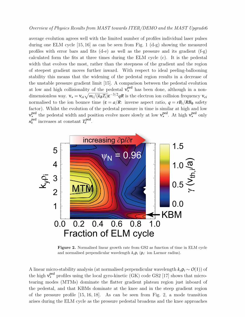
Figure 2. Normalised linear growth rate from GS2 as function of time in ELM cycle
and normalised perpendicular wavelength kyρi (ρi: ion Larmor radius).
A linear micro-stability analysis (at normalised perpendicular wavelength kyρi∼O(1)) of
the high νped? profiles using the local gyro-kinetic (GK) code GS2 [17] shows that micro-
tearing modes (MTMs) dominate the flatter gradient plateau region just inboard of
the pedestal, and that KBMs dominate at the knee and in the steep gradient region
of the pressure profile [15, 16, 18]. As can be seen from Fig. 2, a mode transition
arises during the ELM cycle as the pressure pedestal broadens and the knee approaches
Overview of Physics Results from MAST towards ITER/DEMO and the MAST Upgrade7
ψN =√
(ψ−ψ0)/(ψa−ψ0) ≈ 0.96 (ψ0: poloidal flux at magnetic axis, ψa: magnetic
flux at last closed flux surface). The increasing ∂n/∂r and ∂p/∂r stabilise the MTMs
until KBMs are driven unstable, which may be important in explaining the inward
advance of the pedestal. In the steepest ∂p/∂r region KBMs become more stable due to
increasing bootstrap current [16] and are fully stable at low νped? [18, 19]. Studies using
measured edge current profiles and gyro-kinetic modelling with global codes are needed
to elucidate the role of the KBMs for the pedestal further.
3. ELM mitigation
In ITER and DEMO type-I ELMs need to be mitigated or suppressed to protect the
plasma facing components [20], e.g. by using resonant magnetic perturbations (RMP)
[21–24]. The internal coil set on MAST has recently been upgraded from 12 coils to
18 internal coils, 12 below and 6 above the mid-plane, to study ELM mitigation with
n = 2,3,4,6 RMP fields.
0.0
2.0
4.0
6.0
0
1
2
3
4
5
6
0.20 0.25 0.30 0.35 0.40 0.50
0.20 0.25 0.30 0.35 0.40 0.45 0.50
0.0
2.0
4.0
0
1
2
3
4
5
6
0.20 0.25 0.30 0.35 0.40 0.45 0.50
0.20 0.25 0.30 0.35 0.40 0.50
0.0
0.2
0.4
0.0
0.1
0.2
0.3
0.4
0.5
0.20 0.25 0.30 0.35 0.40 0.45 0.50
0.20 0.25 0.30 0.35 0.40 0.45 0.50
0.0
0.2
0.4
0.1
0.2
0.3
0.4
0.5
0.20 0.25 0.30 0.35 0.40 0.45
0.20 0.25 0.30 0.35 0.40 0.45 0.50
Time (s)
27204 IELM=0 kAt 27205 IELM=5.6 kAt (n=6)
IELM (kAt)
Dα (arb)
ne (x1019 m-3)
Dα (arb)
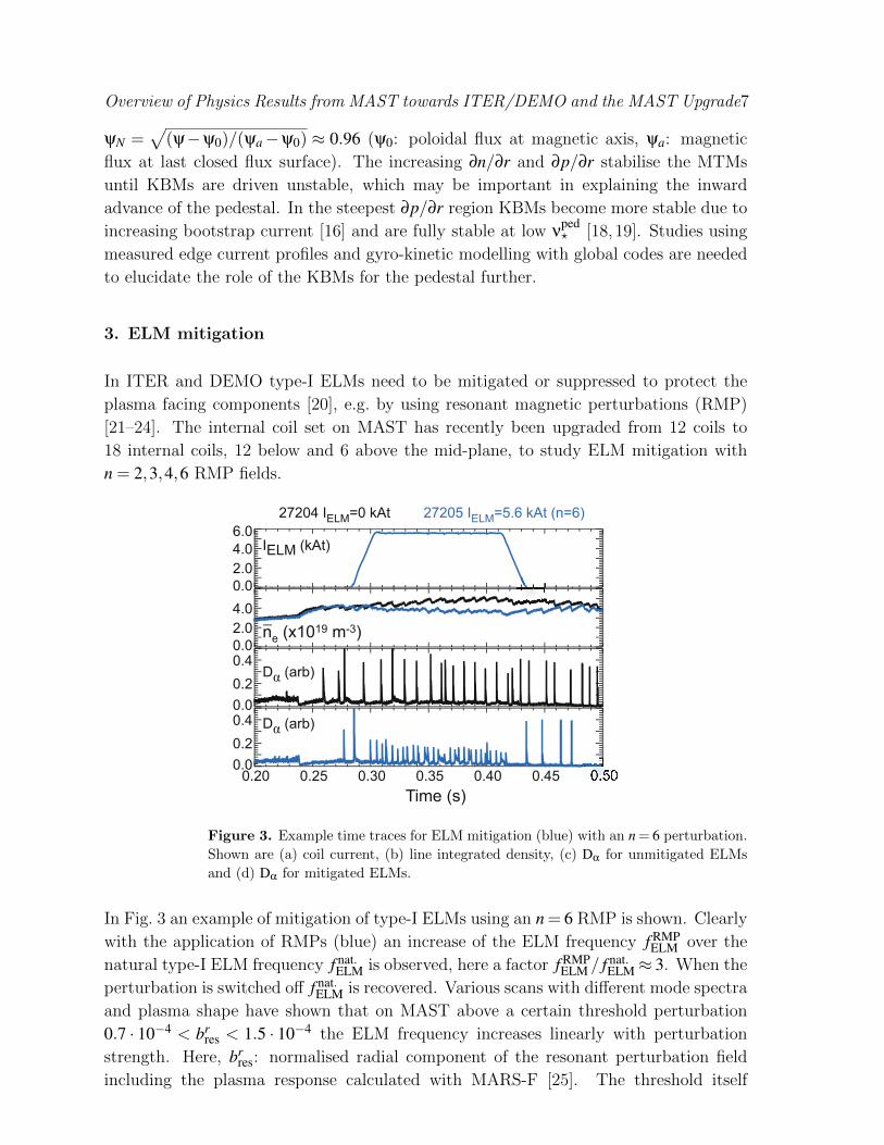
Figure 3. Example time traces for ELM mitigation (blue) with an n = 6 perturbation.
Shown are (a) coil current, (b) line integrated density, (c) Dα for unmitigated ELMs
and (d) Dα for mitigated ELMs.
In Fig. 3 an example of mitigation of type-I ELMs using an n = 6 RMP is shown. Clearly
with the application of RMPs (blue) an increase of the ELM frequency f RMPELM over the
natural type-I ELM frequency f nat.ELM is observed, here a factor f RMP
ELM / f nat.ELM≈ 3. When the
perturbation is switched off f nat.ELM is recovered. Various scans with different mode spectra
and plasma shape have shown that on MAST above a certain threshold perturbation
0.7 · 10−4 < brres < 1.5 · 10−4 the ELM frequency increases linearly with perturbation
strength. Here, brres: normalised radial component of the resonant perturbation field
including the plasma response calculated with MARS-F [25]. The threshold itself
Overview of Physics Results from MAST towards ITER/DEMO and the MAST Upgrade8
depends on the applied spectrum. The ELM energy loss ∆WELM is consistent with
f RMPELM ·∆WELM = const. as for unmitigated ELMs. An increase of f RMP
ELM / f nat.ELM up to 9
has been observed with a particular n = 3 configuration. The upgraded coil set has
now also the unique capability to perform a pitch angle scan of the n = 3 perturbation
at a fixed q95 to test the resonance condition. This is done by keeping the current in
the upper 6 coils constant, whilst changing the ratio of currents in the 12 lower coils
operated in pairs. The sensitivity to the alignment together with modelling including the
plasma response [26] suggests that the perturbation strength close to the X-point plays
an important role to affect the ELMs, although studies have as yet failed to identify a
single parameter for ELM mitigation.
Unstable
Stable
8 10 12 14
1.0
1.2
1.4
1.6
1.8
Normalised pressure gradient
(je
dg
e +
jse
p) /
2 (
MA/m
2)
ma
x
experiment
no RMP
n=3 RMP
DND
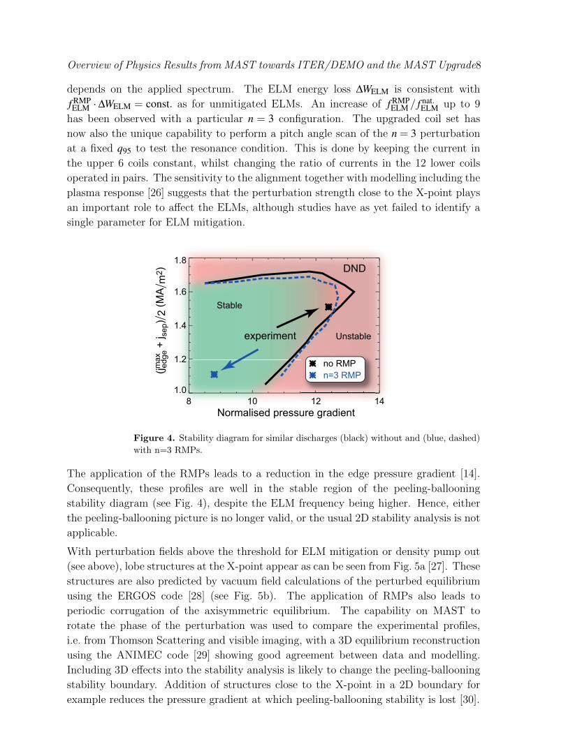
Figure 4. Stability diagram for similar discharges (black) without and (blue, dashed)
with n=3 RMPs.
The application of the RMPs leads to a reduction in the edge pressure gradient [14].
Consequently, these profiles are well in the stable region of the peeling-ballooning
stability diagram (see Fig. 4), despite the ELM frequency being higher. Hence, either
the peeling-ballooning picture is no longer valid, or the usual 2D stability analysis is not
applicable.
With perturbation fields above the threshold for ELM mitigation or density pump out
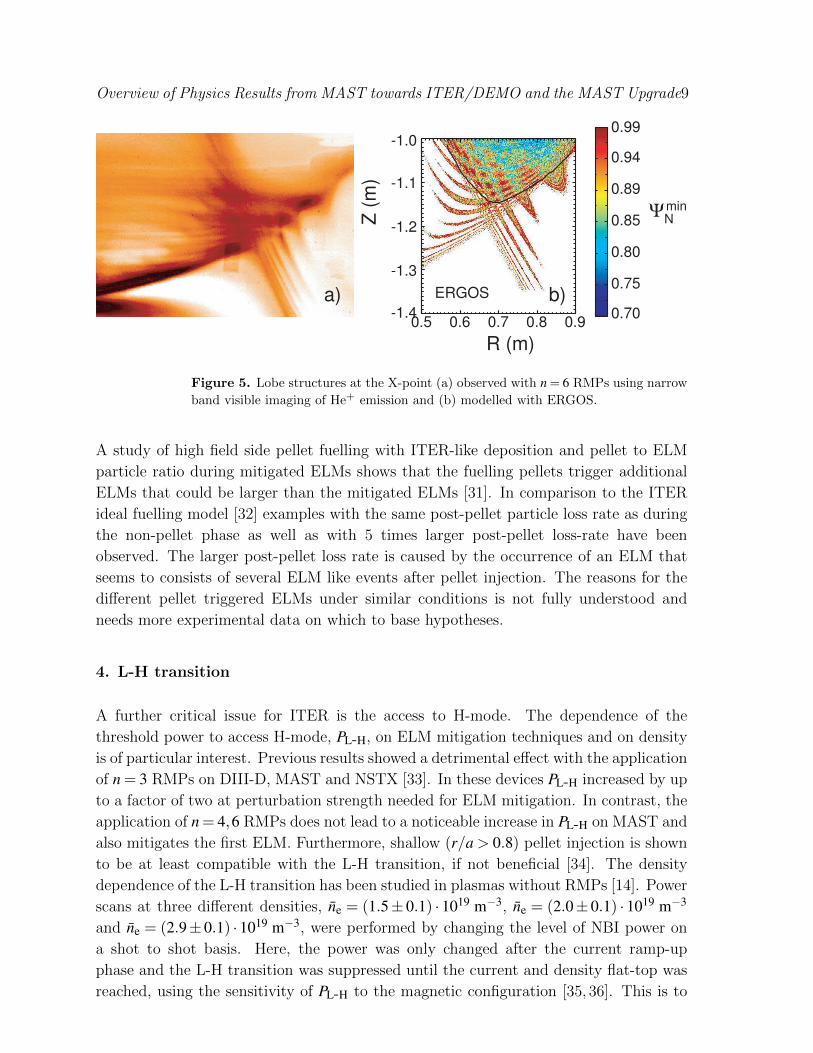
(see above), lobe structures at the X-point appear as can be seen from Fig. 5a [27]. These
structures are also predicted by vacuum field calculations of the perturbed equilibrium
using the ERGOS code [28] (see Fig. 5b). The application of RMPs also leads to
periodic corrugation of the axisymmetric equilibrium. The capability on MAST to
rotate the phase of the perturbation was used to compare the experimental profiles,
i.e. from Thomson Scattering and visible imaging, with a 3D equilibrium reconstruction
using the ANIMEC code [29] showing good agreement between data and modelling.
Including 3D effects into the stability analysis is likely to change the peeling-ballooning
stability boundary. Addition of structures close to the X-point in a 2D boundary for
example reduces the pressure gradient at which peeling-ballooning stability is lost [30].
Overview of Physics Results from MAST towards ITER/DEMO and the MAST Upgrade9
0.70.80.91.0
0.5 0.6 0.7 0.8 0.9-1.4
-1.3
-1.2
-1.1
-1.0
0.5 0.6 0.7 0.8 0.9-1.4
-1.3
-1.2
-1.1
-1.0
0.70
0.75
0.80
0.85
0.89
0.94
0.99
R (m)
Z (
m)
ΨNmin
b)a) ERGOS
Figure 5. Lobe structures at the X-point (a) observed with n = 6 RMPs using narrow
band visible imaging of He+ emission and (b) modelled with ERGOS.
A study of high field side pellet fuelling with ITER-like deposition and pellet to ELM
particle ratio during mitigated ELMs shows that the fuelling pellets trigger additional
ELMs that could be larger than the mitigated ELMs [31]. In comparison to the ITER
ideal fuelling model [32] examples with the same post-pellet particle loss rate as during
the non-pellet phase as well as with 5 times larger post-pellet loss-rate have been
observed. The larger post-pellet loss rate is caused by the occurrence of an ELM that
seems to consists of several ELM like events after pellet injection. The reasons for the
different pellet triggered ELMs under similar conditions is not fully understood and
needs more experimental data on which to base hypotheses.
4. L-H transition
A further critical issue for ITER is the access to H-mode. The dependence of the
threshold power to access H-mode, PL-H, on ELM mitigation techniques and on density
is of particular interest. Previous results showed a detrimental effect with the application
of n = 3 RMPs on DIII-D, MAST and NSTX [33]. In these devices PL-H increased by up
to a factor of two at perturbation strength needed for ELM mitigation. In contrast, the
application of n = 4,6 RMPs does not lead to a noticeable increase in PL-H on MAST and
also mitigates the first ELM. Furthermore, shallow (r/a > 0.8) pellet injection is shown
to be at least compatible with the L-H transition, if not beneficial [34]. The density
dependence of the L-H transition has been studied in plasmas without RMPs [14]. Power
scans at three different densities, ne = (1.5± 0.1) · 1019 m−3, ne = (2.0± 0.1) · 1019 m−3
and ne = (2.9±0.1) ·1019 m−3, were performed by changing the level of NBI power on
a shot to shot basis. Here, the power was only changed after the current ramp-up
phase and the L-H transition was suppressed until the current and density flat-top was
reached, using the sensitivity of PL-H to the magnetic configuration [35, 36]. This is to

Overview of Physics Results from MAST towards ITER/DEMO and the MAST Upgrade10
avoid effects of different current profile evolution on the relative PL-H measurements.
At the lowest density the available power of PNBI = 3.5 MW was not sufficient to access
a clear ELMy H-mode. Instead only an intermediate phase, H, is observed where the
Dα light dithers at frequencies of 4 kHz ≤ fDα≤ 5 kHz. This phase exists to very low
density ne ≈ 1.0 ·1019 m−3 and over a wide range of input power. At the higher density
ELMy H-mode is preceded by a similar phase, but the range in input power is reduced
as well as the duration of this phase before the transition to ELMy H-mode occurs. This
behaviour can be seen from Fig. 6 showing (a) the Dα traces at different densities and
(b) an indicative existence space in Ploss and ne. The periods (∆t < 200 µs) with low
Dα emission represent states of decreased edge turbulence measured with a reflectomer,
beam emission spectroscopy (BES) and fast visible imaging. The periods are too short
for the kinetic profiles to evolve significantly [37].
The dynamics of the toroidal and poloidal He+ flow, representing the radial electric field,
as the plasma enters the low turbulence periods in the H phase is indistinguishable from
the behaviour at the transition where the transport barrier can be sustained. Both
the toroidal and poloidal velocity, measured by Doppler spectroscopy, indicate a more
negative electric field with a stronger gradient in the edge region, just inside the last
closed flux surface as can be seen from Fig. 7a,b. However, turbulent filaments are
seen to erupt from the plasma ∼ 50 µs before the flow shear is lost. This would be
H-phase ELMy H-mode~
a)
0.60.81.01.21.41.6
0.25
0.30
0.35
0.20.4
0.6
0.8
1.0
�-10 �-5 0 5 10 15�
0.160.170.180.190.200.21
mid
-pla
ne
Dα in
ten
sity (
arb
. u
nits) ne = 2.8×10¹⁹ m-3
PNBI = 2.4 MW
-10 �-5�� 0
ne = 1.4×10¹⁹ m-3
PNBI = 2.3 MW
ne = 2.0×10¹⁹ m-3
PNBI = 2.2 MW
ne = 2.0×10¹⁹ m-3
PNBI = 1.9 MW
Time with respect to transition (ms)
Lin
e a
ve
rag
ed
de
nsity
−
−
−
−
L-mode
ELMy H-mode
H-mode
(I-phase)
~
b)
1.0 1.5 2.0 2.5 3.00
1
2
3
4
5
Plo
ss (
MW
)
ne (1019m-3)_
Figure 6. (a) Dα traces for discharges at different densities close to the L-H transition.
The density increases from bottom to top. The H-phase is shown in green and the
ELMy H-mode in red. The L to H-phase transition is marked by the vertical line. For
the medium density case two power values are shown leading to a sustained H-phase
with the lower power and a delayed transition to ELMy H-mode at higher power. (b)
Indicative Ploss versus ne existence space with measurement points overlaid.

Overview of Physics Results from MAST towards ITER/DEMO and the MAST Upgrade11
LC
FS
LC
FS
�
�
�
�
�
-8
-6
-4
-2
0
2
-10
-8
-6
-4
-2
0
2
1.40 1.42 1.44 1.40 1.42 1.44
vp
ol (
km
/s)
He
+
vto
r (k
m/s
)H
e+
#28180
t-tmax (μs)
-150 -100 -50 0 50 100 150
Dα-in
t. (
a.u
.)
Er more
negative
Er more
negative
b)a)
c)Error bars represent
statistical variation in
boxcar analysis.
R (m) R (m)
Figure 7. Boxcar averaged (a) poloidal and (b) toroidal He+ flow profiles with respect
to (c) the boxcar averaged Dα emission as proxy for the edge turbulence.
consistent with a picture where the turbulence transports vorticity out of the edge
region. Pending a detailed comparison this phase has some signatures of the I-phase
observed in other devices [38,39], a limit cycle oscillation between turbulence driven flow
shear and plasma turbulence. The dynamics of the flow seems to be incompatible at
least with simple predator-prey models [40, 41], where the predator, turbulence driven
flow shear, feeds on the prey, the turbulence. Here, a simple phase relation between
flow shear and turbulence would be expected [42]. Geodesic acoustic modes (GAM),
also often connected to the I-phase [38], have been observed in Ip = 0.4 MA Ohmic
discharges on MAST and are found to be affected by RMPs suggesting a coupling to
Alfvenic perturbations [43]
Overview of Physics Results from MAST towards ITER/DEMO and the MAST Upgrade12
SXD
scaled
0
1
2
3
4x10⁶
Energy
flux
-0.2 0 0.20
2
4
6
ΔRsep (m)
x1022
Particle
flux
qt (
Wm
-2)
Γt (
s-1
m-2
)
0.6 0.8 1.0 1.2 1.4 1.6-2.1
-2.0
-1.9
-1.8
-1.7
-1.6
-1.5
-1.4
Electron density (m-3)
R (m)
Z (
m)
0.5
1.0
1.5
2.0
x1019
conventional divertor (CD)
ncore
= 2.8x10¹⁹(m-3)
Ploss
= 1.7 (MW)
a)
b)
c)
Super-X(SXD)
22
icle
CD
SXD
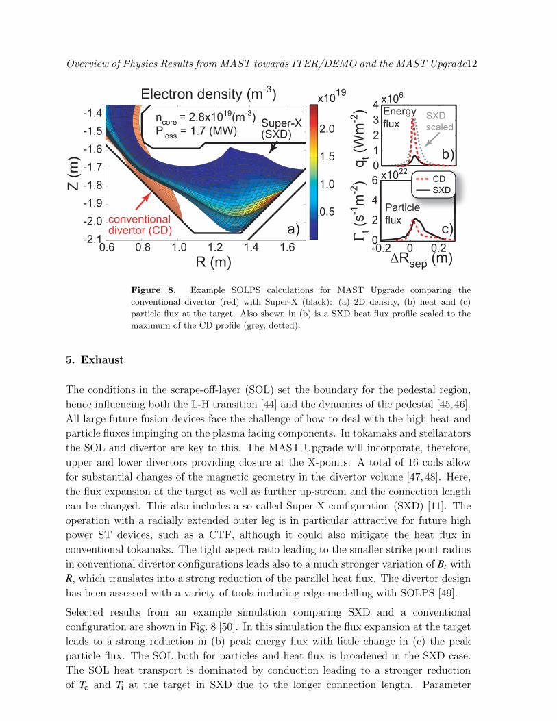
Figure 8. Example SOLPS calculations for MAST Upgrade comparing the
conventional divertor (red) with Super-X (black): (a) 2D density, (b) heat and (c)
particle flux at the target. Also shown in (b) is a SXD heat flux profile scaled to the
maximum of the CD profile (grey, dotted).
5. Exhaust
The conditions in the scrape-off-layer (SOL) set the boundary for the pedestal region,
hence influencing both the L-H transition [44] and the dynamics of the pedestal [45,46].
All large future fusion devices face the challenge of how to deal with the high heat and
particle fluxes impinging on the plasma facing components. In tokamaks and stellarators
the SOL and divertor are key to this. The MAST Upgrade will incorporate, therefore,
upper and lower divertors providing closure at the X-points. A total of 16 coils allow
for substantial changes of the magnetic geometry in the divertor volume [47, 48]. Here,
the flux expansion at the target as well as further up-stream and the connection length
can be changed. This also includes a so called Super-X configuration (SXD) [11]. The
operation with a radially extended outer leg is in particular attractive for future high
power ST devices, such as a CTF, although it could also mitigate the heat flux in
conventional tokamaks. The tight aspect ratio leading to the smaller strike point radius
in conventional divertor configurations leads also to a much stronger variation of Bt with
R, which translates into a strong reduction of the parallel heat flux. The divertor design
has been assessed with a variety of tools including edge modelling with SOLPS [49].
Selected results from an example simulation comparing SXD and a conventional
configuration are shown in Fig. 8 [50]. In this simulation the flux expansion at the target
leads to a strong reduction in (b) peak energy flux with little change in (c) the peak
particle flux. The SOL both for particles and heat flux is broadened in the SXD case.
The SOL heat transport is dominated by conduction leading to a stronger reduction
of Te and Ti at the target in SXD due to the longer connection length. Parameter

Overview of Physics Results from MAST towards ITER/DEMO and the MAST Upgrade13
scans have been performed with SOLPS to test the robustness of specific Upgrade
design features. This is necessary to also address uncertainties arising from the ad-hoc
anomalous diffusivity representing the turbulent cross field (radial) transport in SOLPS.
Furthermore, a 1D model has been developed (SOLF1D) and successfully benchmarked
against the SOLPS calculation [50, 50]. Here, a strong reduction of heat flux and is
observed when the divertor leg is stretched to a larger radius or if the recycling source
is increased with the SOL volume.
LP (Ti=Te)
IRLP+RFEA
-0.05 0.00 0.05 0.10 0.150.0
0.1
0.2
0.3
0.4
0.5
0.6
inter-ELM
qt (
MW
/m2)
R-Rsep(m)tgt
Figure 9. Comparison of
heat flux profiles at the lower
outer strike point from Langmuir
probes (LP, black) assuming Te =
Ti, (red) IR camera and (blue)
probes using Ti from the divertor
RFEA (blue).
naturalmitigated
0 5 10 150
5
10
15
20
qpeak (M
W/m
2)
∆WELM (kJ)MHD
inter-ELM heat flux
Figure 10. Measured peak
heat flux to the target versus
ELM energy loss for natural
(black dots) and mitigated (red
triangles) ELMs. The dashed
line is a linear fit to the data.
Assumptions not only enter SOL simulations, but also data interpretation. The ion
temperature in front of the target plate is one of such assumptions, affecting the
interpretation of Langmuir probe measurements. For the first time a retarding field
energy analyser (RFEA) has now been used in the down-stream divertor region of
MAST to measure Ti close to the target [47, 51, 52]. Fig. 9 shows heat flux profiles at
the lower outer strike-point during an inter ELM period in a Ip = 0.9 MA type I ELMy
H-mode from Langmuir probes assuming Ti = Te (black dots), the IR camera (red circles)
and Langmuir probe data using Ti from the RFEA measurement (blue squares). The
inclusion of the measured ion temperature Ti/Te ≤ 3 clearly brings the IR and Langmuir
probe measurements into closer agreement in the high heat flux region. The inclusion
of the Ti data leads to an overestimate of the heat flux most pronounced in the region
0.04 m≤ R−Rsep ≤ 0.07 m. With increasing collisionality Ti/Te evolves towards unity as
expected. The divertor RFEA measurements are augmented by a similar system at the
Overview of Physics Results from MAST towards ITER/DEMO and the MAST Upgrade14
outer mid-plane, thus allowing the study of the changes of Ti towards the divertor in the
SOL for the first time in a tokamak. As shown previously for the pedestal region [37]
also in the mid-plane SOL Ti > Te holds [51,53] agreeing well with edge charge exchange
measurements.
These new measurements enhance confidence in the heat load measurements with the
IR camera during mitigated and unmitigated ELMs [24, 54]. As can be seen from
Fig. 10 the peak heat flux to the target is reduced for mitigated ELMs corresponding
to their ELM size, which follows the same ∆W · fELM = const. dependence as natural
ELMs [54]. In addition the wetted area decreases with decreasing ELM size as has
been observed in other devices. At vanishing ELM size (∆W MHDELM → 0 kJ) the linearly
extrapolated peak heat flux would be much larger than the measured inter ELM heat flux
qt ≈ 0.5−1.5 MW/m2 and a deviation from the linear trend may occur, although MAST
data currently show no evidence for this. Strike point spitting during ELM mitigation
with RMPs is measured from CII narrow band visible imaging in the divertor. These
measurements agree well with ERGOS vacuum modelling of the perturbations, though
at reduced RMP coil current in ERGOS implying some screening by the plasma.
Not only the peak heat flux, but also the heat flux profile is important to assess divertor
performance in future devices. A database of MAST L- and H-mode discharges has
been constructed [55] using a new way of fitting target heat flux profiles developed on
JET and ASDEX Upgrade [56] to feed into a multi-machine database [57] and to arrive
at a scaling of the heat flux decay length, λq, with machine parameters. However, a first
principle understanding of the SOL transport processes leading to the profiles of ne, Te
and qheat at the target is needed. Many aspects of the L-mode filament dynamics at
the mid-plane in MAST seemed to be captured by electrostatic interchange turbulence
as captured in simulations with ESEL [58,59]. The simulations not only reproduce the
ion saturation current mean profile, but also many of the statistical properties of the
observed turbulence. Parameter scans of these ESEL simulations have been used to
arrive at scaling λq at the mid-plane [58]. To make predictions for the target profiles the
simple model for the parallel transport in ESEL needs to be improved. Nevertheless, the
scaling laws , which are in broad agreement to recent experimental scaling [60], reproduce
the expectation that λq does not simply increase with machine size confirming the
importance of the forthcoming experimentation in MAST Upgrade [47,58]. In particular
it is found that λq ∝ I−1p as experimentally seen on many devices for L-mode [60] and
H-mode [57] and increases with the parallel length scale in the SOL, both quantities can
be changed in the MAST Upgrade over a large range.
6. Current drive and fast particle physics
Current profile, j(r), control and non-inductive current drive are likely needed in future
tokamaks and in particular in STs. The JINTRAC integrated suite of codes [61],
routinely used for modelling JET discharges, has been interfaced with the MAST data to
Overview of Physics Results from MAST towards ITER/DEMO and the MAST Upgrade15c
r/a
EFIT with MSEinitial+50ms
TRANSP initial+50ms
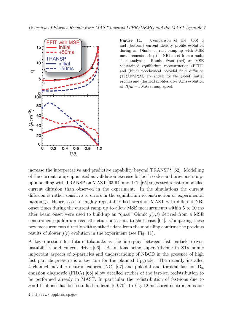
Figure 11. Comparison of the (top) q
and (bottom) current density profile evolution
during an Ohmic current ramp-up with MSE
measurements using the NBI onset from a multi
shot analysis. Results from (red) an MSE
constrained equilibrium reconstruction (EFIT)
and (blue) neoclassical poloidal field diffusion
(TRANSP)XS are shown for the (solid) initial
profiles and (dashed) profiles after 50ms evolution
at dI/dt = 5 MA/s ramp speed.
increase the interpretative and predictive capability beyond TRANSP§ [62]. Modelling
of the current ramp-up is used as validation exercise for both codes and previous ramp-
up modelling with TRANSP on MAST [63,64] and JET [65] suggested a faster modelled
current diffusion than observed in the experiment. In the simulations the current
diffusion is rather sensitive to errors in the equilibrium reconstruction or experimental
mappings. Hence, a set of highly repeatable discharges on MAST with different NBI
onset times during the current ramp up to allow MSE measurements within 5 to 10 ms
after beam onset were used to build-up an “quasi” Ohmic j(r, t) derived from a MSE
constrained equilibrium reconstruction on a shot to shot basis [64]. Comparing these
new measurements directly with synthetic data from the modelling confirms the previous
results of slower j(r) evolution in the experiment (see Fig. 11).
A key question for future tokamaks is the interplay between fast particle driven
instabilities and current drive [66]. Beam ions being super-Alfvenic in STs mimic
important aspects of α-particles and understanding of NBCD in the presence of high
fast particle pressure is a key aim for the planned Upgrade. The recently installed
4 channel movable neutron camera (NC) [67] and poloidal and toroidal fast-ion Dα
emission diagnostic (FIDA) [68] allow detailed studies of the fast-ion redistribution to
be performed already in MAST. In particular the redistribution of fast-ions due to
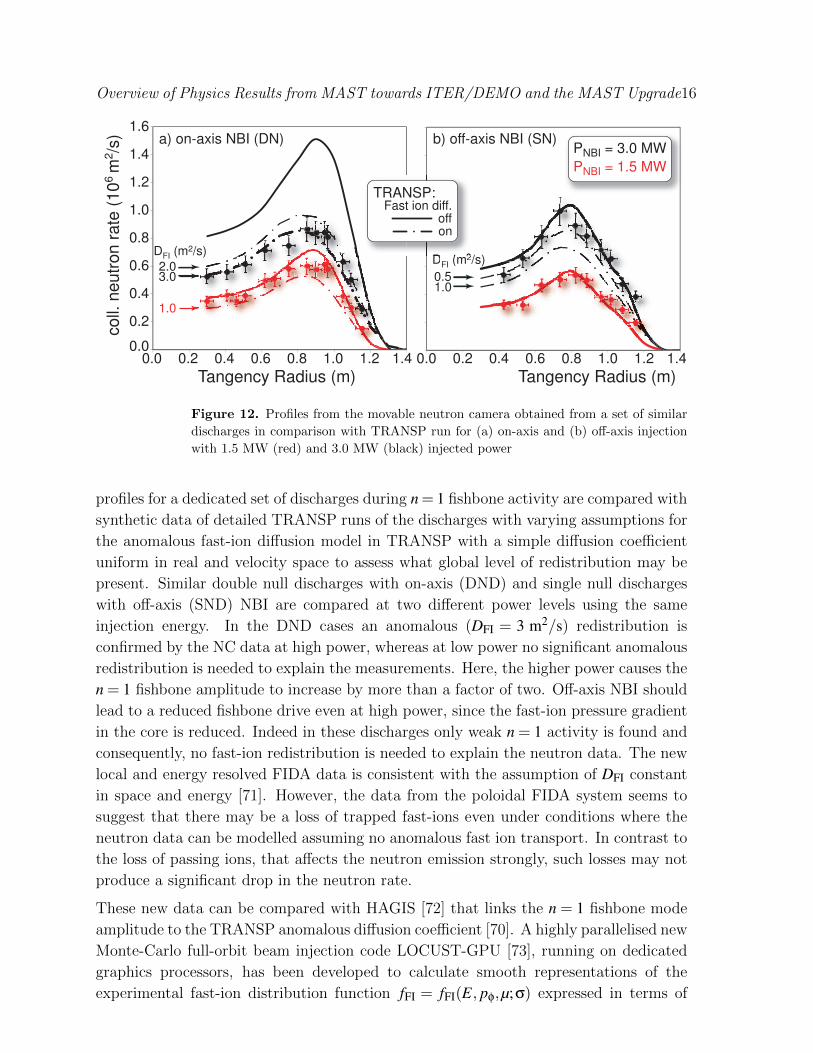
n = 1 fishbones has been studied in detail [69,70]. In Fig. 12 measured neutron emission
§ http://w3.pppl.transp.gov
Overview of Physics Results from MAST towards ITER/DEMO and the MAST Upgrade16
Tangency Radius (m)0.0 0.2 0.4 0.6 0.8 1.0 1.2 1.4
Tangency Radius (m)0.0 0.2 0.4 0.6 0.8 1.0 1.2 1.4
0.0
0.2
0.4
0.6
0.8
1.0
1.2
1.4
1.6coll.
neutr
on r
ate
(10
6 m
2/s
)
PNBI = 3.0 MW
PNBI = 1.5 MW
1.0
2.03.0 0.5
a) on-axis NBI (DN) b) off-axis NBI (SN)
1.0
DFI (m2/s)
DFI (m2/s)
Fast ion diff.off
TRANSP:
on
Figure 12. Profiles from the movable neutron camera obtained from a set of similar
discharges in comparison with TRANSP run for (a) on-axis and (b) off-axis injection
with 1.5 MW (red) and 3.0 MW (black) injected power
profiles for a dedicated set of discharges during n = 1 fishbone activity are compared with
synthetic data of detailed TRANSP runs of the discharges with varying assumptions for
the anomalous fast-ion diffusion model in TRANSP with a simple diffusion coefficient
uniform in real and velocity space to assess what global level of redistribution may be
present. Similar double null discharges with on-axis (DND) and single null discharges
with off-axis (SND) NBI are compared at two different power levels using the same
injection energy. In the DND cases an anomalous (DFI = 3 m2/s) redistribution is
confirmed by the NC data at high power, whereas at low power no significant anomalous
redistribution is needed to explain the measurements. Here, the higher power causes the
n = 1 fishbone amplitude to increase by more than a factor of two. Off-axis NBI should
lead to a reduced fishbone drive even at high power, since the fast-ion pressure gradient
in the core is reduced. Indeed in these discharges only weak n = 1 activity is found and
consequently, no fast-ion redistribution is needed to explain the neutron data. The new
local and energy resolved FIDA data is consistent with the assumption of DFI constant
in space and energy [71]. However, the data from the poloidal FIDA system seems to
suggest that there may be a loss of trapped fast-ions even under conditions where the
neutron data can be modelled assuming no anomalous fast ion transport. In contrast to
the loss of passing ions, that affects the neutron emission strongly, such losses may not
produce a significant drop in the neutron rate.
These new data can be compared with HAGIS [72] that links the n = 1 fishbone mode
amplitude to the TRANSP anomalous diffusion coefficient [70]. A highly parallelised new
Monte-Carlo full-orbit beam injection code LOCUST-GPU [73], running on dedicated
graphics processors, has been developed to calculate smooth representations of the
experimental fast-ion distribution function fFI = fFI(E, pφ,µ;σ) expressed in terms of

Overview of Physics Results from MAST towards ITER/DEMO and the MAST Upgrade17
constants of motion, to be used directly in the HAGIS modelling extending the
calculations using model fast-ion distribution functions presented previously [8]. This,
together with the incorporation of collisional drag into the HAGIS modelling of resonant
beam ions, has led to an improved understanding of the interactions of these ions
with various electromagnetic modes, as well as fast-ion redistribution during fishbones.
In particular the inclusion of dynamical friction is important when modelling super-
Alfvenic particles. It has been found that the redistribution during fishbones can
be expressed as effective diffusion and convection both scaling quadratically with the
mode amplitude [70]. However, the transport coefficients computed using HAGIS are
not sufficient to account for the drops in neutron emission during fishbone excitation,
suggesting that other processes may be contributing to the fast ion redistribution.
1018
1016
10
10
10
650 652 654 656 658 660 662 664
Inte
nsity (
s-1
nm
-1m
-2sr-1
)
Wavelength (nm)
Beam
emissionHaloFIDAtotal
LOCUST-GPU simulated Dα emission
Figure 13. Simulated Dα emission from LOCUST-GPU. FIDA and halo emission
result from charge exchange between injected neutrals and, respectively, fast and bulk
deuterium ions, while beam emission is produced by the de-excitation of injected
neutrals.
Other mechanisms for fast-ion redistribution and fast-ion losses have also been studied.
The ion loss due to the toroidal field ripple has been modelled with CUEBIT [74] and
shown to contribute only 0.1 m2/s or less to DFI. The changes to the fast-ion distribution
caused by sawtooth crashes and an internal n = 1 kink mode (long-lived mode, LLM) [75]
have also been measured with the NC and FIDA [67, 71]. During the LLM neutron
emission is reduced in the core. The FIDA data are best matched during this phase using
a core localised DFI ≈ 6 m2/s in contrast to the lower but global redistribution during
fishbone activity. Synthetic FIDA and NC diagnostics are embedded in LOCUST-GPU,
for better data analysis. An example of the modelled Dα spectrum is shown in Fig. 13.
At the low toroidal field in MAST the high ratio of fast ion velocity to the Alfven
speed (up to 2.5) leads to the excitation of compressional Alfven eigenmodes (CAE) [76]
Overview of Physics Results from MAST towards ITER/DEMO and the MAST Upgrade18
with n > 0 rotating in the co-current direction. Such modes have to be excited by the
anomalous Doppler resonance condition ω− k‖v‖ = lωci with l =−1 (ωci: ion cyclotron
frequency) and are driven by the beam anisotropy T‖ > T⊥. Usually CAEs are excited
at the normal Doppler resonance l = +1 and have n < 0.
7. Core transport
0.0 0.2 0.4 0.6 0.8 1.0 1.2
normalised flux radius(ψN)1/2
10-3
10-2
10-1
kin. e- coll.
Experiment
Background
NEMORB includingflow
P P O
P O PO O O
δn
e/n
e
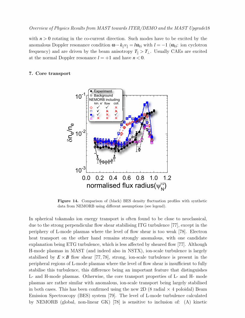
Figure 14. Comparison of (black) BES density fluctuation profiles with synthetic
data from NEMORB using different assumptions (see legend).
In spherical tokamaks ion energy transport is often found to be close to neoclassical,
due to the strong perpendicular flow shear stabilising ITG turbulence [77], except in the
periphery of L-mode plasmas where the level of flow shear is too weak [78]. Electron
heat transport on the other hand remains strongly anomalous, with one candidate
explanation being ETG turbulence, which is less affected by sheared flow [77]. Although
H-mode plasmas in MAST (and indeed also in NSTX), ion-scale turbulence is largely
stabilised by E ×B flow shear [77, 78], strong, ion-scale turbulence is present in the
peripheral regions of L-mode plasmas where the level of flow shear is insufficient to fully
stabilise this turbulence, this difference being an important feature that distinguishes
L- and H-mode plasmas. Otherwise, the core transport properties of L- and H- mode
plasmas are rather similar with anomalous, ion-scale transport being largely stabilised
in both cases. This has been confirmed using the new 2D (8 radial × 4 poloidal) Beam
Emission Spectroscopy (BES) system [79]. The level of L-mode turbulence calculated
by NEMORB (global, non-linear GK) [78] is sensitive to inclusion of: (A) kinetic
Overview of Physics Results from MAST towards ITER/DEMO and the MAST Upgrade19
electrons, (B) collisions and (C) rotation shear. The flow shear, as well as all other
prescribed profiles in these calculations, has been taken from a detailed TRANSP
analysis of the experiment. Inclusion of (A) and (B) brings simulated turbulence
amplitude within factor of 2-3 to the experimental data and adding (C) may improve
agreement further [80]. Also, at high parallel flow shear subcritical turbulence may
cause a finite ion heat flux in regimes where the linear growth rate of the micro-
instabilities vanishes [81, 82]. The experimental dependence of R/LTi (L−1f ≡ ∇ ln f :
gradient length) on toroidal flow shear and q/ε is in reasonable agreement with cyclone
base-case simulations (a generalised circular s-alpha, tokamak equilibrium, frequently
used to benchmark simulations [83]) to obtain the zero-turbulence manifold [80,82].
1 10 100τc [µ sec]
1
10
100
τ * [µ
se
c]
1 10 100τc [µ sec]
1
10
100
τ st [
µse
c]
1 10 100τc [µ sec]
1
10
100
τ M [µ
se
c]
1 10 100 1000τc [µ sec]
1
10
100
1000
τ sh [
µse
c]
0.0 5.0
Ln/L
Ti
(a) (b)
(c) (d)
Figure 15. Comparison of turbulence correlation time τc with (a) drift time τ?, (b)
streaming time, (c) magnetic drift time and (d) the perpendicular shearing time.
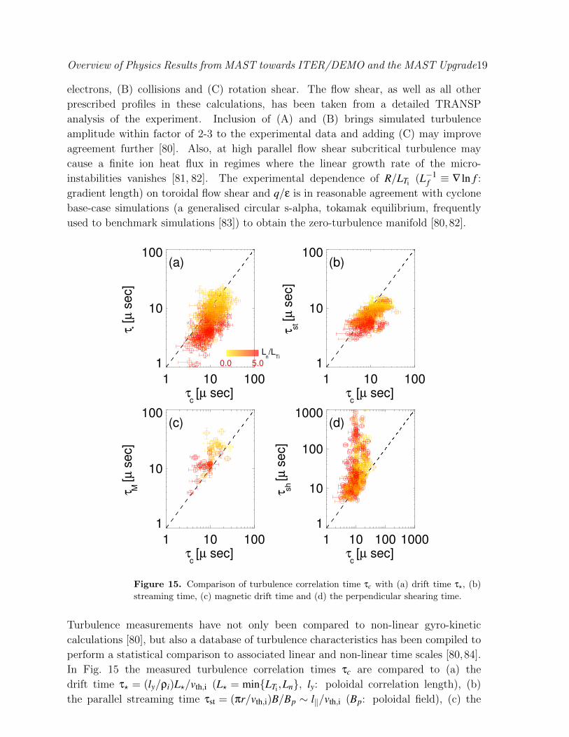
Turbulence measurements have not only been compared to non-linear gyro-kinetic
calculations [80], but also a database of turbulence characteristics has been compiled to
perform a statistical comparison to associated linear and non-linear time scales [80,84].
In Fig. 15 the measured turbulence correlation times τc are compared to (a) the
drift time τ? = (ly/ρi)L?/vth,i (L? = min{LTi,Ln}, ly: poloidal correlation length), (b)
the parallel streaming time τst = (πr/vth,i)B/Bp ∼ l‖/vth,i (Bp: poloidal field), (c) the
Overview of Physics Results from MAST towards ITER/DEMO and the MAST Upgrade20
magnetic drift time τM = (lx/ρi)R/vth,i and (d) the perpendicular velocity shearing time
τsh = [(Bp/B)∂Uφ/∂r]−1 (Uφ: toroidal mean flow). The data show that τc ∼ τst ∼ τM,
which indicates a ‘grand critical balance’ [81] where these basic turbulence characteristics
can be predicted from the equilibrium quantities alone. Furthermore, this implies
that the parallel and perpendicular correlation length within the flux surface are not
independent [84].
It is evident from Fig. 15(d) that for most of the data in our ion-scale turbulence
database the E×B shearing time τsh is longer than the correlation time of the turbulence
τc. This indicates that where strong ion-scale turbulence is observed, i.e. primarily in
the periphery of L-mode plasmas, that the E ×B shearing rate is not the controlling
factor governing the de-correlation of the turbulence. It is conjectured in Ref. [84] that
a significant component of the turbulent amplitude due to zonal flows, which does not
contribute to the amplitude of the density fluctuations detected by the BES system,
may be playing a role in the de-correlation of the turbulence instead.
8. Core stability
–0.2 –0.2 0.0 0.1x
–5
–4
–3
–2
–1
(ra
dia
ns)
–5
–4
–3
–2
–1
(ra
dia
ns)
#24623
model
exp.
Te
a)
b)
Te –4
–2
0
2
4
Norm
. G
row
th R
ate
[a.u
.]
0.298 0.317 0.335
Time (s)
–4
–2
0
2
4
TotalClassical + NonlinearBootstrapGGJPolarisation
c)
#23447
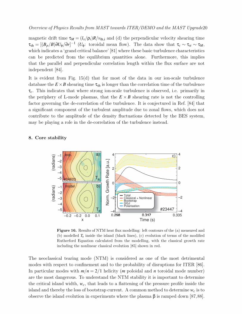
Figure 16. Results of NTM heat flux modelling: left contours of the (a) measured and
(b) modelled Te inside the island (black lines), (c) evolution of terms of the modified
Rutherford Equation calculated from the modelling, with the classical growth rate
including the nonlinear classical evolution [85] shown in red.
The neoclassical tearing mode (NTM) is considered as one of the most detrimental
modes with respect to confinement and to the probability of disruptions for ITER [86].
In particular modes with m/n = 2/1 helicity (m poloidal and n toroidal mode number)
are the most dangerous. To understand the NTM stability it is important to determine
the critical island width, wc, that leads to a flattening of the pressure profile inside the
island and thereby the loss of bootstrap current. A common method to determine wc is to
observe the island evolution in experiments where the plasma β is ramped down [87,88].
Overview of Physics Results from MAST towards ITER/DEMO and the MAST Upgrade21
Examining the heat transport inside the island, however, is a more fundamental method
to understand NTM stability. Using field-programmable gate array (FPGA) based event
triggering of the Thomson scattering system [89,90] the Te and ne profiles at 8 time slices
through the rotating 2/1 island of an NTM have been measured for the first time in
an ST [91]. A 2D simple heat transport model assuming divergence-free diffusive heat
transport in the island with constant parallel and perpendicular heat diffusivity has
been used to fit to the Te profile. The model has been validated against the island width
estimation during β ramps. Fig. 16a,b shows the good comparison between modelled
and experimental Te profiles. From the modelling of an ensemble of similar discharges
with saturated NTMs the different terms in the modified Rutherford equation have been
estimated with errors resulting from the measurement errors (see Fig. 16c) with the most
unstable term being the bootstrap drive and all other terms small and stabilising. A
key feature of this analysis is that no specific models for parallel or perpendicular heat
transport are assumed, which has not been the case in many previous analyses of NTM
growth. The same technique of intelligent event triggering can be used to mitigate
the NTM in H-mode by shifting the plasma briefly of DND triggering a short L-mode
transition [36] leading to a temporary reduction of βp [90].
Disruption avoidance and mitigation are key features for ITER due to the large forces
and the potential for runaway electron generation. On MAST a systematic study of
disruption mitigation by massive gas injection with respect to gas load and impurity
species [47, 92, 93] supports findings on other devices. The peak energy load can be
reduced by 60% compared to unmitigated disruptions and best results with respect to
penetration speed and thermal quench time are achieved with an Ar(10%)/He mix. The
relative reduction of energy is found to increase with increasing stored energy.
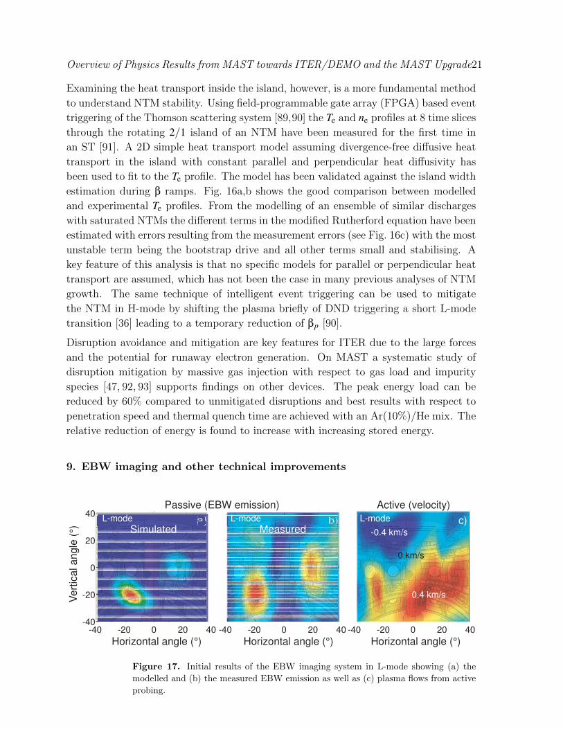
9. EBW imaging and other technical improvements
Simulated Measuredc)
-0.4 km/s
0 km/s
0.4 km/s
L-mode L-mode L-mode
-40 -20 0 20 40-40
-20
0
20
40
Horizontal angle (°) Horizontal angle (°)
Vert
ical angle
(°)
Passive (EBW emission)
-40 -20 0 20 40-40 -20 0 20 40
Active (velocity)
Horizontal angle (°)
Figure 17. Initial results of the EBW imaging system in L-mode showing (a) the
modelled and (b) the measured EBW emission as well as (c) plasma flows from active
probing.
Overview of Physics Results from MAST towards ITER/DEMO and the MAST Upgrade22
One of the most exciting novel diagnostics on MAST is the electron Bernstein emission
synthetic aperture imaging [94, 95], which measures the emission window in poloidal
and toroidal angle at ∆t ≈ 10 µs time resolution with 10 MHz sampling rate. This is
achieved by using an array of 8 antennas to synthesise a 2D image and 16 frequencies
for probing at different plasma densities (radial positions) giving 3D information of the
EBW emission. Fig. 17a) shows the modelled EBW emission using a 1D full wave mode-
coupling code complemented with 3D ray-tracing [96] and Fig. 17b) the corresponding
measurement. The angular positions of the emission cones show excellent agreement,
with the vertical elongation in the experimental data caused by the shape of the antenna
array, and should allow ELM-resolved measurements of j(r) in the steep gradient region
of the pedestal. The system simultaneously also records active data using one of the
antennas as emitter and recording the reflected power similar to Doppler back scattering,
providing density turbulence and velocity fluctuation measurements. A 2D image of the
turbulent plasma flows reconstructed from the Doppler shift of the reflected signal is
shown in Fig. 17c. The analysis of the large amount of data is ongoing, but first results
are promising with respect to flows and ELM resolved edge current densities.
As several other systems on MAST this diagnostic is also driven by FPGAs and the
application of FPGAs in fusion technology on MAST is growing with development
and individual programming done in-house. Apart from the event triggering, already
mentioned, an intelligent drive of the TAE antenna has been developed to stop the drive
power briefly whilst measuring the plasma response and a system to improve the vertical
feedback control is in development to be used on MAST Upgrade.
New piezo-electric valve mechanisms were developed for the HFS mid-plane gas fuelling
and the movable gas nozzle. The former, currently operated with a solenoid drive,
now enables the mid-plane HFS fuelling to be shut off, thus avoiding the low pedestal
temperatures prevalent with continuous fuelling. Here, the valve mechanism is extended
from the outside of the vessel to provide sealing close to the plasma. This gives similar
fuelling rates to the old system at ten times lower gas pressure and has enabled disruption
mitigation studies with massive gas injection from the high field side. The latter allows a
modulated gas influx with up-to 500 Hz close to the plasma with response times < 1 msand fuelling rates of the order of 1021 particles/s e.g. for impurity transport studies. Both
valve systems act as prototypes for the fuelling system design on the MAST Upgrade.
In particular the HFS mid-plane fuelling location is foreseen to be the main fuelling
location on the Upgrade and needs to be able to support density feedback.
10. Summary
MAST continues to make important contributions to ITER/DEMO physics and the
general understanding of tokamak plasmas as well as building the physics basis for future
spherical tokamak (ST) applications on the way to fusion power. New and sometimes
unique measurements such as electron Bernstein wave imaging are fundamental to the
Overview of Physics Results from MAST towards ITER/DEMO and the MAST Upgrade23
progress. The Upgrade (under procurement) will further strengthen these research
capabilities and recent studies have aided the design and clarified the physics capabilities.
In particular the new divertor design in the MAST Upgrade will help to address the
critical exhaust issue, which is even more challenging in the compact ST geometry.
Initial modelling suggests that a strong reduction in target heat flux in the Upgrade
may be accomplished with a radially extended outer leg.
On MAST mitigation of edge localised modes (ELM) using resonant magnetic
perturbations with n = 3,4,6 has been demonstrated with the increase in ELM frequency
likely to be caused by the 3D deformation of the plasma, and has been shown to be
compatible with pellet fuelling. The peak heat flux during an ELM is found to be
proportional to the ELM energy loss with mitigated ELMs following the same trend as
natural ELMs. At low collisionality the ion temperature in the divertor, measured using
a retarding field energy analyser, exceeds the electron temperature showing that the
usual assumption of equality between these temperatures for probe data analysis is not
always justified. The measured edge velocity fluctuations during an oscillatory phase
preceding the formation of the edge transport barrier (L-H transition) raise questions
for simple predator-prey like dynamics between the turbulence driven flow shear and
turbulence suppression by the flow shear. Core ion scale turbulence in L-mode has
been measured to be consistent with a “grand-critical-balance”, where the characteristic
turbulent time scales are of the same order of magnitude. Global gyro-kinetic modelling
shows reasonable agreement with the measured fluctuation amplitude over the full
plasma radius, when kinetic electron effects and collisions are taken into account.
Measurements of the 2D temperature profile inside an island due to a neoclassical tearing
mode enable a detailed analysis of the island evolution without assuming a specific
model for the parallel and perpendicular heat transport inside the island. The fast-ion
redistribution by fishbones is found to be low with off-axis neutral beam injection. This
bodes well for the MAST Upgrade and its planned off-axis heating as well as for future
ST devices.
Acknowledgements: This work was funded by the RCUK Energy Programme under
grant EP/I501045 and the European Communities under the contract of Association
between EURATOM and CCFE. The views and opinions expressed herein do not
necessarily reflect those of the European Commission.
References:
[1] A. Darke, J. R. Harbar, J. H. Hay, J. B. Hicks, J. W. Hill, J. S. McKenzie, Morris A. W., M. P. S.
Nightingale, T. N. Todd, G. M. Voss, and J. R. Watkins. MAST: A mega amp spherical tokamak.
In 18th Symposium on Fusion Technology, 22-26 Aug., Karlsruhe, Germany, 1994.
[2] M. Ono et al. Overview of initial NSTX experimental results. Nucl. Fusion, 41(10):1435–1447,
2001.
[3] M. Shimada et al. Progress in the ITER Physics Basis Chapter 1: Overview and Summary. Nucl.
Fusion, 47:S1, 2007.
[4] T.C. Hender, G.M. Voss, and N.P. Taylor. Spherical tokamak volume neutron source. Fusion
Engineering and Design, 45(3):265 – 279, 1999.
Overview of Physics Results from MAST towards ITER/DEMO and the MAST Upgrade24
[5] Y-K M Peng, P J Fogarty, T W Burgess, D J Strickler, B E Nelson, J Tsai, C A Neumeyer, R Bell,
C Kessel, J Menard, D Gates, B LeBlanc, D Mikkelsen, E Fredrickson, L Grisham, J Schmidt,
P Rutherford, S Sabbagh, A Field, A Sykes, I Cook, O Mitarai, and Y Takase. A component test
facility based on the spherical tokamak. Plasma Physics and Controlled Fusion, 47(12B):B263,
2005.
[6] G.M. Voss, S. Davis, A. Dnestrovskij, A. Kirk, P.J. Knight, M. Loughlin, M.H. O’Brien,
D. Sychugov, A. Tabasso, and H.R. Wilson. Conceptual design of a component test facility
based on the spherical tokamak. Fusion Engineering and Design, 83(10-12):1648 – 1653, 2008.
Proceedings of the Eight International Symposium of Fusion Nuclear Technology - ISFNT-8 SI.
[7] H. Meyer, R.J. Akers, F. Alladio, L.C. Appel, K.B. Axon, N. Ben Ayed, P. Boerner, R.J. Buttery,
P.G. Carolan, D. Ciric, C.D. Challis, I.T. Chapman, G. Coyler, J.W. Connor, N.J. Conway,
S. Cowley, M. Cox, G.F. Counsell, G. Cunningham, A. Darke, M. deBock, G. deTemmerman,
R.O. Dendy, J. Dowling, A. Yu Dnestrovskij, Yu.N. Dnestrovskij, B. Dudson, D. Dunai,
M. Dunstan, A.R. Field, A. Foster, L. Garzotti, K. Gibson, M.P. Gryaznevich, W. Guttenfelder,
N.C. Hawkes, J. Harrison, P. Helander, T.C. Hender, B. Hnat, M.J. Hole, D.F. Howell, M. Duc
Hua, A. Hubbard, M. Istenic, N. Joiner, D. Keeling, A. Kirk, H.R. Koslowski, Y. Liang, M. Lilley,
S. Lisgo, B. Lloyd, G.P. Maddison, R. Maingi, A. Mancuso, S.J. Manhood, R. Martin, G.J.
McArdle, J. McCone, C. Michael, P. Micozzi, T. Morgan, A.W. Morris, D.G. Muir, E. Nardon,
G. Naylor, M.R. O’Brien, T. O’Gorman, A. Patel, S.D. Pinches, J. Preinhaelter, M.N. Price,
E. Rachlew, D. Reiter, C.M. Roach, V. Rozhansky, S. Saarelma, A. Saveliev, R. Scannell,
S.E. Sharapov, V. Shevchenko, S. Shibaev, H. Smith, G.E. Staebler, D. Stork, J. Storrs,
A. Sykes, S. Tallents, P. Tamain, D. Taylor, D. Temple, N. Thomas-Davies, A. Thornton,
A. Thyagaraja, M.R. Turnyanskiy, J. Urban, M. Valovic, R.G.L. Vann, F. Volpe, G Voss,
M.J. Walsh, S.E.V. Warder, R. Watkins, H.R. Wilson, M. Windridge, M. Wisse, A. Zabolotski,
S. Zoletnik, O. Zolotukhin, the MAST, and NBI teams. Overview of physics results from MAST.
Nucl. Fusion, 49(10):104017 (13pp), 2009.
[8] B. Lloyd, R.J. Akers, F. Alladio, S. Allan, L.C. Appel, M. Barnes, N.C. Barratt, N. Ben Ayed,
B.N. Breizman, M. Cecconello, C.D. Challis, I.T. Chapman, D. Ciric, G. Colyer, J.W. Connor,
N.J. Conway, M. Cox, S.C. Cowley, G. Cunningham, A. Darke, M. De Bock, E. Delchambre,
G. De Temmerman, R.O. Dendy, P. Denner, M.D. Driscoll, B. Dudson, D. Dunai, M. Dunstan,
S. Elmore, A.R. Field, G. Fishpool, S. Freethy, L. Garzotti, K.J. Gibson, M.P. Gryaznevich,
W. Guttenfelder, J Harrison, R.J. Hastie, N.C. Hawkes, T.C. Hender, B. Hnat, D.F. Howell,
M.-D. Hua, A. Hubbard, G. Huysmans, D. Keeling, Y.C. Kim, A. Kirk, Y. Liang, M.K. Lilley,
M. Lisak, S. Lisgo, Y.Q. Liu, G.P. Maddison, R. Maingi, S.J. Manhood, R. Martin, G.J. McArdle,
J. McCone, H. Meyer, C. Michael, S. Mordijck, T. Morgan, A.W. Morris, D.G. Muir, E. Nardon,
G. Naylor, M.R. O’Brien, T. O’Gorman, J. Palenık, A. Patel, S.D. Pinches, M.N. Price, C.M.
Roach, V. Rozhansky, S. Saarelma, S.A. Sabbagh, A. Saveliev, R. Scannell, S.E. Sharapov,
V. Shevchenko, S. Shibaev, D. Stork, J. Storrs, W. Suttrop, A. Sykes, P. Tamain, D. Taylor,
D. Temple, N. Thomas-Davies, A. Thornton, M.R. Turnyanskiy, M. Valovic, R.G.L. Vann,
G. Voss, M.J. Walsh, S.E.V. Warder, H.R. Wilson, M. Windridge, M Wisse, S. Zoletnik, the
MAST, and NBI teams. Overview of physics results from mast. Nuclear Fusion, 51(9):094013,
2011.
[9] D. Stork, H. Meyer, et al. The upgrade to the Mega Amp Spherical Tokamak. In Fusion Energy
2010, Proc. 23rd int. Conf. Daejon, 2010. (Vienna: IAEA) CD-ROM file ICC/P5-06 and
http://www-naweb.iaea.org.uk/napc/physics/FEC/FEC2010/html/index.htm.
[10] A. W. Morris. MAST: Results and Upgrade Activities. Plasma Science, IEEE Transactions on,
40(3):682 –691, march 2012.
[11] P. M. Valanju, M. Kotschenreuther, S. M. Mahajan, and J. Canik. Super-X divertors and high
power density fusion devices. Physics of Plasmas, 16(5):056110, 2009.
[12] D. D. Ryutov. Geometrical properties of a“snowflake”divertor. Physics of Plasmas, 14(6):064502,
2007.

Overview of Physics Results from MAST towards ITER/DEMO and the MAST Upgrade25
[13] P. B. Snyder, R. J. Groebner, A. W. Leonard, T. H. Osborne, and H. R. Wilson. Development
and validation of a predictive model for the pedestal height. Phys. of Plasmas, 16(5):056118,
2009.
[14] R. Scannell et al. Dynamics of the plasma edge during the L-H transi-
tion and H-mode in MAST(EXC/P7-22). In 24th IAEA Fusion Energy Con-
ference, 8-13 Oct., San Diego, USA, 2012. available from http://www-
naweb.iaea.org/napc/physics/FEC/FEC2012/html/proceedings.pdf.
[15] D Dickinson, S Saarelma, R Scannell, A Kirk, C M Roach, and H R Wilson. Towards the
construction of a model to describe the inter-ELM evolution of the pedestal on MAST. Plasma
Physics and Controlled Fusion, 53(11):115010, 2011.
[16] D. Dickinson, C. M. Roach, S. Saarelma, R. Scannell, A. Kirk, and H. R. Wilson. Kinetic
Instabilities that Limit β in the Edge of a Tokamak Plasma: A Picture of an H-Mode Pedestal.
Phys. Rev. Lett., 108:135002, Mar 2012.
[17] M. Kotschenreuther, G. Rewoldt, and WM Tang. Comparison of initial value and eigenvalue codes
for kinetic toroidal plasma instabilities. Comp. Phys. Comm., 88(2-3):128–140, 1995.
[18] C. R. Roach et al. Gyrokinetic Instabilities in an Evolving Tokamak H-mode (TH/5-1). In 24th
IAEA Fusion Energy Conference, 8-13 Oct., San Diego, USA, 2012. available from http://www-
naweb.iaea.org/napc/physics/FEC/FEC2012/html/proceedings.pdf.
[19] S. Saarelma et al. Pedestal Modelling Based on Ideal MHD And Gyrokinetic Stabil-
ity Analyses on JET And ITER Plasmas (TH/P3-10). In 24th IAEA Fusion En-
ergy Conference, 8-13 Oct., San Diego, USA, 2012. available from http://www-
naweb.iaea.org/napc/physics/FEC/FEC2012/html/proceedings.pdf.
[20] A. Loarte, G. Saibene, R. Sartori, V. Riccardo, P. Andrew, J. Paley, W. Fundamenski, T. Eich,
A. Herrmann, G. Pautasso, et al. Transient heat loads in current fusion experiments,
extrapolation to ITER and consequences for its operation. Physica Scripta, T128:222–228,
2007.
[21] T.E. Evans, R.A. Moyer, K.H. Burrell, M.E. Fenstermacher, I. Joseph, A.W. Leonard, T.H.
Osborne, G.D. Porter, M.J. Schaffer, P.B. Snyder, et al. Edge stability and transport
control with resonant magnetic perturbations in collisionless tokamak plasmas. Nature Physics,
2(6):419–423, 2006.
[22] E. Nardon, A. Kirk, N. Ben Ayed, M. Becoulet, P. Cahyna, T.E. Evans, G. Huysmans, H.R.
Koslowski, Y. Liang, S. Saarelma, and P.R. Thomas. ELM control by resonant magnetic
perturbations on JET and MAST. Journal of Nuclear Materials, 390-391:773 – 776, 2009.
Proceedings of the 18th International Conference on Plasma-Surface Interactions in Controlled
Fusion Device.
[23] A. Kirk, E. Nardon, R. Akers, M. Becoulet, G. De Temmerman, B. Dudson, B. Hnat, Y.Q.
Liu, R. Martin, P. Tamain, D. Taylor, and the MAST team. Resonant magnetic perturbation
experiments on MAST using external and internal coils for ELM control. Nuclear Fusion,
50(3):034008, 2010.
[24] A. Kirk et al. Understanding ELM mitigation by resonant magnetic per-
turbations on MAST(EX/3-2). In 24th IAEA Fusion Energy Confer-
ence, 8-13 Oct., San Diego, USA, 2012. available from http://www-
naweb.iaea.org/napc/physics/FEC/FEC2012/html/proceedings.pdf.
[25] Yueqiang Liu, A. Kirk, and E. Nardon. Full toroidal plasma response to externally applied
nonaxisymmetric magnetic fields. Physics of Plasmas, 17(12):122502, 2010.
[26] Yueqiang Liu, A. Kirk, Y. Gribov, M.P. Gryaznevich, T.C. Hender, and E. Nardon. Modelling of
plasma response to resonant magnetic perturbation fields in MAST and ITER. Nuclear Fusion,
51(8):083002, 2011.
[27] A. Kirk, J. Harrison, Yueqiang Liu, E. Nardon, I. T. Chapman, and P. Denner. Observation of
Lobes near the X Point in Resonant Magnetic Perturbation Experiments on MAST. Phys. Rev.
Lett., 108:255003, Jun 2012.

Overview of Physics Results from MAST towards ITER/DEMO and the MAST Upgrade26
[28] M. Becoulet, E. Nardon, G. Huysmans, W. Zwingmann, P. Thomas, M. Lipa, R. Moyer, T. Evans,
V. Chuyanov, Y. Gribov, A. Polevoi, G. Vayakis, G. Federici, G. Saibene, A. Portone, A. Loarte,
C. Doebert, C. Gimblett, J. Hastie, and V. Parail. Numerical study of the resonant magnetic
perturbations for Type I edge localized modes control in ITER. Nuclear Fusion, 48(2):024003,
2008.
[29] W.A. Cooper, S.P. Hirshman, P. Merkel, J.P. Graves, J. Kisslinger, H.F.G. Wobig, Y. Narushima,
S. Okamura, and K.Y. Watanabe. Three-dimensional anisotropic pressure free boundary
equilibria. Computer Physics Communications, 180(9):1524 – 1533, 2009.
[30] I.T. Chapman, A. Kirk, S. Saarelma, J.R. Harrison, R. Scannell, and the MAST Team. Towards
understanding ELM mitigation: the effect of axisymmetric lobe structures near the X-point on
ELM stability. Nuclear Fusion, 52(12):123006, 2012.
[31] M Valovic, G Cunningham, L Garzotti, C Gurl, A Kirk, G Naylor, A Patel, R Scannell,
A J Thornton, and the MAST team. Pellet fuelling of plasmas with edge localized modes
mitigation by resonant magnetic perturbations in MAST. Plasma Physics and Controlled
Fusion, 55(2):025009, 2013.
[32] A.S. Kukushkin, A.R. Polevoi, H.D. Pacher, G.W. Pacher, and R.A. Pitts. Physics requirements on
fuel throughput in ITER. Journal of Nuclear Materials, 415(1, Supplement):S497–S500, 2011.
Proceedings of the 19th International Conference on Plasma-Surface Interactions in Controlled
Fusion.
[33] M.E. Fenstermacher et al. ELM Control by Resonant Magnetic Perturbations: Overview of
Research by the PEP ITPA Group. Technical Report EFDA-JET-CP(10)08/31, EFDA-JET,
2010.
[34] M. Valovic, L. Garzotti, C. Gurl, R. Akers, J. Harrison, C. Michael, G. Naylor, R. Scannell, and
the MAST team. H-mode access by pellet fuelling in the MAST tokamak. Nuclear Fusion,
52(11):114022, 2012.
[35] H. Meyer, P. G. Carolan, N. J. Conway, G. F. Counsell, G. Cunningham, A. R. Field, A. Kirk,
K. G. McClements, M. Price, D. Taylor, and the MAST team. Improved H-mode access in
connected DND in MAST. Plasma Phys. Contr. Fusion, 47(6):843–867, 2005.
[36] H. Meyer, Y. Andrew, P. G. Carolan, G. Cunningham, E. Delchambre, A. R. Field, A. Kirk,
P. Molchanov, V. Rozhansky, S. Voskoboynikov, and MAST and NBI Teams. Active control of
the H-mode transition on MAST. Plasma Phys. Contr. Fusion, 50:015005, 2008.
[37] H. Meyer, M.F.M. De Bock, N.J. Conway, S.J. Freethy, K. Gibson, J. Hiratsuka, A. Kirk, C.A.
Michael, T. Morgan, R. Scannell, G. Naylor, S. Saarelma, A.N. Saveliev, V.F. Shevchenko,
W. Suttrop, D. Temple, R.G.L. Vann, the MAST, and NBI teams. LaASh transition and
pedestal studies on mast. Nuclear Fusion, 51(11):113011, 2011.
[38] G. D. Conway, C. Angioni, F. Ryter, P. Sauter, and J. Vicente. Mean and Oscillating Plasma
Flows and Turbulence Interactions across the L-H Confinement Transition. Phys. Rev. Lett.,
106:065001, Feb 2011.
[39] L. Schmitz, L. Zeng, T. L. Rhodes, J. C. Hillesheim, E. J. Doyle, R. J. Groebner, W. A. Peebles,
K. H. Burrell, and G. Wang. Role of Zonal Flow Predator-Prey Oscillations in Triggering the
Transition to H-Mode Confinement. Phys. Rev. Lett., 108:155002, Apr 2012.
[40] A.J. Lotka. Contribution to the Theory of Periodic Reaction. J. Phys. Chem., 14:271–274, 1910.
[41] J.-N. Leboeuf, L. A. Charlton, and B. A. Carreras. Shear flow effects on the nonlinear evolution
of thermal instabilities. Physics of Fluids B: Plasma Physics, 5(8):2959–2966, 1993.
[42] K. Miki and P.H. Diamond. Novel states of pre-transition edge turbulence emerging from shearing
mode competition. Nuclear Fusion, 51(10):103003, 2011.
[43] J R Robinson, B Hnat, P Dura, A Kirk, P Tamain, and the MAST Team. Interaction between
a low-frequency electrostatic mode and resonant magnetic perturbations in MAST. Plasma
Physics and Controlled Fusion, 54(10):105007, 2012.
[44] B. LaBombard, J. E. Rice, A. E. Hubbard, J. W. Hughes, M. Greenwald, R. S. Granetz, J. H. Irby,
Y. Lin, B. Lipschultz, E. S. Marmar, K. Marr, D. Mossessian, R. Parker, W. Rowan, N. Smick,

Overview of Physics Results from MAST towards ITER/DEMO and the MAST Upgrade27
J. A. Snipes, J. L. Terry, S. M. Wolfe, and S. J. Wukitch Alcator C-Mod Team. Transport-driven
scrape-off layer flows and the X-point dependence of the L-H power threshold in Alcator C-Mod.
Phys. of Plasmas, 12(5):056111, 2005.
[45] J.M. Canik, R. Maingi, V.A. Soukhanovskii, R.E. Bell, H.W. Kugel, B.P. LeBlanc, and T.H.
Osborne. Measurements and 2-D modeling of recycling and edge transport in discharges with
lithium-coated PFCs in NSTX. Journal of Nuclear Materials, 415(1, Supplement):S409 – S412,
2011. Proceedings of the 19th International Conference on Plasma-Surface Interactions in
Controlled Fusion.
[46] G.F. Matthews. Plasma operation with an all metal first-wall: Comparison of an ITER-like wall
with a carbon wall in JET. Journal of Nuclear Materials, 438(0):S2aASS10, 2013.
[47] G. Fishpool et al. MAST Contributions to the Exhaust Challenge, Including Testing of Super-X
(EX/P5-17). In 24th IAEA Fusion Energy Conference, 8-13 Oct., San Diego, USA, 2012. avail-
able from http://www-naweb.iaea.org/napc/physics/FEC/FEC2012/html/proceedings.pdf.
[48] G. Fishpool, J. Canik, G. Cunningham, J. Harrison, I. Katramados, A. Kirk, M. Kovari, H. Meyer,
and R. Scannell. MAST-Upgrade divertor facility and assessing performance of long-legged
divertors. Journal of Nuclear Materials, 438(0):S356aASS359, 2013.
[49] X. Bonnin, D. Coster, C.S. Pitcher, R. Schneider, D. Reiter, V. Rozhansky, S. Voskoboynikov, and
H. Burbaumer. Improved modelling of detachment and neutral-dominated regimes using the
SOLPS B2-Eirene code. Journal of Nuclear Materials, 313-316(0):909 – 913, 2003. Proceedings
of the 15th International Conference on Plasma-Surface Interactions in Controlled Fusion.
[50] E. Havlıckova, W. Fundamenski, M. Wischmeier, G. Fishpool, and D. Coster. Numerical studies
of effects associated with the Super-X divertor on target parameters in MAST-U. Journal of
Nuclear Materials, 438(0):S545 – S549, 2013.
[51] S Elmore, S Y Allan, A Kirk, G Fishpool, J Harrison, P Tamain, M Kocan, R Gaffka, R Stephen,
J W Bradley, and the MAST Team. Upstream and divertor ion temperature measurements on
MAST by retarding field energy analyser. Plasma Physics and Controlled Fusion, 54(6):065001,
2012.
[52] S. Elmore, S.Y. Allan, A. Kirk, A.J. Thornton, J.R. Harrison, P. Tamain, M. Kocan, and J.W.
Bradley. Scrape-off layer ion temperature measurements at the divertor target in {MAST} by
retarding field energy analyser. Journal of Nuclear Materials, 438(0):S1212 – S1215, 2013.
[53] S.Y. Allan, S. Elmore, A. Kirk, M. Kocan, and P. Tamain. Ion energy measurements on MAST
using a midplane RFEA. Journal of Nuclear Materials, 438(0):S530 – S535, 2013.
[54] A.J. Thornton, A. Kirk, I.T. Chapman, and J.R. Harrison. Divertor heat fluxes and profiles during
mitigated and unmitigated edge localised modes (ELMs) on the Mega Amp Spherical Tokamak
(MAST). Journal of Nuclear Materials, 438(0):S199 – S202, 2013.
[55] J Harrison et al. L-mode and inter-ELM Divertor Particle and Heat Flux Width Scaling on MAST.
In 20th Int. Conf. on Plasma Surface Interactions, Aachen, Germany, 2012.
[56] T. Eich, B. Sieglin, A. Scarabosio, W. Fundamenski, R. J. Goldston, and A. Herrmann. Inter-
ELM Power Decay Length for JET and ASDEX Upgrade: Measurement and Comparison with
Heuristic Drift-Based Model. Phys. Rev. Lett., 107:215001, Nov 2011.
[57] T. Eich et al. Scaling of the Tokamak near Scrape-off Layer H-mode Power
Width and Implications for ITER (ITR/1-1). In 24th IAEA Fusion Energy
Conference, 8-13 Oct., San Diego, USA, 2012. available from http://www-
naweb.iaea.org/napc/physics/FEC/FEC2012/html/proceedings.pdf.
[58] F Militello, P Tamain, W Fundamenski, A Kirk, V Naulin, A H Nielsen, and the MAST team.
Experimental and numerical characterization of the turbulence in the scrape-off layer of MAST.
Plasma Physics and Controlled Fusion, 55(2):025005, 2013.
[59] F. Militello, W. Fundamenski, V. Naulin, and A.H. Nielsen. Numerical investigation of Scrape
Off Layer anomalous particle transport for MAST parameters. Journal of Nuclear Materials,
438(0):S530 – S535, 2013.
[60] A. Scarabosio, T. Eich, A. Herrmann, and B. Sieglin. Outer target heat fluxes and power
Overview of Physics Results from MAST towards ITER/DEMO and the MAST Upgrade28
decay length scaling in L-mode plasmas at JET and AUG. Journal of Nuclear Materials,
438, Supplement(0):S426 – S430, 2013. Proceedings of the 20th International Conference on
Plasma-Surface Interactions in Controlled Fusion Devices.
[61] S. Wiesen et al. JINTRAC–JET modelling suite. JET ITC-Report, EFDA-JET, 2008.
[62] R. J. Hawryluk. An emperical approach to tokamak transport. In B. Coppi et al., editors, Physics
of plasmas close to thermonuclear conditions, volume 1. CEC, Brussels, 1980.
[63] D. Keeling, R. Akers, C. D. Challis, G. Cunningham, and H. Meyer. Tayloring the q-profile on
MAST for scenario optimisation. In 35th EPS Plasma Physics Conf., 9-13 June, Hersonissos,
Greece, 2008. Available at http://epsppd.epfl.ch/Hersonissos/start.html.
[64] D. Keeling, R J Akers, M.F.M. de Bock, C.D. Challis, A. Michael, C. A.and Patel, and the
MAST team. Test of current diffusion modelling in MAST current ramp-up. In 38th EPS
Plasma Physics Conf., 27 June - 1 July, Strasbourg, France, 2011.
[65] I. Jenkins, M. Baruzzo, M. Brix, C.D. Challis, N.C. Hawkes, J. Litaudon, X.and Mailloux, F.G.
Rimini, P.C. de Vries, and JET EFDA Contributors. Test of Current Ramp Modelling for AT
Regimes in JET. In 37th EPS Plasma Physics Conf.,21-25 June, Dublin, Ireland, 2010.
[66] M. Turnyanskiy, D.L. Keeling, R.J. Akers, G. Cunningham, N.J. Conway, H. Meyer, C.A. Michael,
and S.D. Pinches. Study of the fast ion confinement and current profile control on mast. Nucl.
Fusion, 49(6):065002 (9pp), 2009.
[67] M. Cecconello, S. Sangaroon, M. Turnyanskiy, S. Conroy, I. Wodniak, R.J. Akers, G. Ericsson, and
the MAST Team. Observation of fast ion behaviour with a neutron emission profile monitor in
MAST. Nuclear Fusion, 52(9):094015, 2012.
[68] C A Michael, N Conway, B Crowley, O Jones, W W Heidbrink, S Pinches, E Braeken, R Akers,
C Challis, M Turnyanskiy, A Patel, D Muir, R Gaffka, and S Bailey. Dual view FIDA
measurements on MAST. Plasma Physics and Controlled Fusion, 55(9):095007, 2013.
[69] M. Turnyanskiy, C.D. Challis, R.J. Akers, M. Cecconello, D.L. Keeling, A. Kirk, R. Lake, S.D.
Pinches, S. Sangaroon, and I. Wodniak. Measurement and control of the fast ion redistribution
on MAST. Nuclear Fusion, 53(5):053016, 2013.
[70] S. D. Pinches et al. Development of a Predictive Capability for Fast Ion
Behaviour in MAST(TH/P3-34). In 24th IAEA Fusion Energy Confer-
ence, 8-13 Oct., San Diego, USA, 2012. available from http://www-
naweb.iaea.org/napc/physics/FEC/FEC2012/html/proceedings.pdf.
[71] C.A. Michael et al. Dual view FIDA measurements on MAST. submitted to Plasma Phys. Control.
Fusion.
[72] S.D. Pinches, L.C. Appel, J. Candy, S.E. Sharapov, H.L. Berk, D. Borba, B.N. Breizman, T.C.
Hender, K.I. Hopcraft, G.T.A. Huysmans, and W. Kerner. The {HAGIS} self-consistent
nonlinear wave-particle interaction model. Computer Physics Communications, 111(1-3):133
– 149, 1998.
[73] R. Akers et al. GPGPU Monte Carlo Calculation of Gyro-Phase Resolved Fast ion and n-state
Resolved Neutral Deuterium Distributions. In 39th EPS Plasma Physics Conf., 2-6 June,
Stockholm, Sweden, page P5.131, 2012.
[74] K. G. McClements and M. J. Hole. Toroidal ripple transport of beam ions in the mega-ampere
spherical tokamak. Physics of Plasmas, 19(7):072514, 2012.
[75] I.T. Chapman, M.-D. Hua, S.D. Pinches, R.J. Akers, A.R. Field, J.P. Graves, R.J. Hastie, C.A.
Michael, and the MAST Team. Saturated ideal modes in advanced tokamak regimes in MAST.
Nuclear Fusion, 50(4):045007, 2010.
[76] N.N. Gorelenkov, E.D. Fredrickson, W.W. Heidbrink, N.A. Crocker, S. Kubota, and W.A. Peebles.
Discrete compressional Alfven eigenmode spectrum in tokamaks. Nuclear Fusion, 46(10):S933,
2006.
[77] C M Roach, I G Abel, R J Akers, W Arter, M Barnes, Y Camenen, F J Casson, G Colyer, J W
Connor, S C Cowley, D Dickinson, W Dorland, A R Field, W Guttenfelder, G W Hammett,
R J Hastie, E Highcock, N F Loureiro, A G Peeters, M Reshko, S Saarelma, A A Schekochihin,
Overview of Physics Results from MAST towards ITER/DEMO and the MAST Upgrade29
M Valovic, and H R Wilson. Gyrokinetic simulations of spherical tokamaks. Plasma Physics
and Controlled Fusion, 51(12):124020, 2009.
[78] S Saarelma, P Hill, A Bottino, G Colyer, A R Field, B McMillan, A Peeters, C M Roach, and the
MAST team. Global gyrokinetic turbulence simulations of MAST plasmas. Plasma Physics
and Controlled Fusion, 54(8):085012, 2012.
[79] A. R. Field, D. Dunai, R. Gaffka, Y. c. Ghim, I. Kiss, B. Meszaros, T. Krizsanoczi, S. Shibaev, and
S. Zoletnik. Beam emission spectroscopy turbulence imaging system for the MAST spherical
tokamak. Review of Scientific Instruments, 83(1):013508, 2012.
[80] A. R. Field et al. Characterisation of ion scale turbulence in MAST(EXC/P-129). In 24th IAEA
Fusion Energy Conference, 8-13 Oct., San Diego, USA, 2012. available from http://www-
naweb.iaea.org/napc/physics/FEC/FEC2012/html/proceedings.pdf.
[81] M. Barnes, F. I. Parra, E. G. Highcock, A. A. Schekochihin, S. C. Cowley, and C. M. Roach.
Turbulent Transport in Tokamak Plasmas with Rotational Shear. Phys. Rev. Lett., 106:175004,
Apr 2011.
[82] E. G. Highcock, A. A. Schekochihin, S. C. Cowley, M. Barnes, F. I. Parra, C. M. Roach, and
W. Dorland. Zero-Turbulence Manifold in a Toroidal Plasma. Phys. Rev. Lett., 109:265001,
Dec 2012.
[83] R. E. Waltz and R. L. Miller. Ion temperature gradient turbulence simulations and plasma flux
surface shape. Physics of Plasmas, 6(11):4265–4271, 1999.
[84] Y.-c. Ghim, A. A. Schekochihin, A. R. Field, I. G. Abel, M. Barnes, G. Colyer, S. C. Cowley, F. I.
Parra, D. Dunai, and S. Zoletnik. Experimental Signatures of Critically Balanced Turbulence
in MAST. Phys. Rev. Lett., 110:145002, Apr 2013.
[85] R. J. Hastie, F. Militello, and F. Porcelli. Nonlinear saturation of tearing mode islands. Phys.
Rev. Lett., 95:065001, Aug 2005.
[86] J.A. Wesson, R.D. Gill, M. Hugon, F.C. SchAijller, J.A. Snipes, D.J. Ward, D.V. Bartlett,
D.J. Campbell, P.A. Duperrex, A.W. Edwards, R.S. Granetz, N.A.O. Gottardi, T.C. Hender,
E. Lazzaro, P.J. Lomas, N. Lopes Cardozo, K.F. Mast, M.F.F. Nave, N.A. Salmon, P. Smeulders,
P.R. Thomas, B.J.D. Tubbing, M.F. Turner, and A. Weller. Disruptions in JET. Nuclear Fusion,
29(4):641, 1989.
[87] R. J. Buttery, O. Sauter, R. Akers, M. Gryaznevich, R. Martin, C. D. Warrick, H. R. Wilson, and
the MAST Team. Neoclassical tearing physics in the spherical tokamak mast. Phys. Rev. Lett.,
88:125005, Mar 2002.
[88] O Sauter, R J Buttery, R Felton, T C Hender, D F Howell, and contributors to the EFDA-
JET Workprogramme. Marginal β-limit for neoclassical tearing modes in JET H-mode
discharges. Plasma Physics and Controlled Fusion, 44(9):1999, 2002.
[89] G.A. Naylor. An FPGA based control unit for synchronization of laser Thomson scattering
measurements to plasma events on MAST. Fusion Engineering and Design, 85(3-4):280 – 285,
2010. Proceedings of the 7th IAEA Technical Meeting on Control, Data Acquisition, and Remote
Participation for Fusion Research.
[90] T. O’Gorman, G. Naylor, K. J. Gibson, B. Huang, G. J. McArdle, R. Scannell, S. Shibaev,
J. A. Snape, and N. Thomas-Davies. A field programmable gate array unit for the diagnosis
and control of neoclassical tearing modes on MAST. Review of Scientific Instruments,
83(10):10E312, 2012.
[91] J A Snape, K J Gibson, T O’Gorman, N C Barratt, K Imada, H R Wilson, G J Tallents, I T
Chapman, and the MAST team. The influence of finite radial transport on the structure and
evolution of m/n = 2/1 neoclassical tearing modes on MAST. Plasma Physics and Controlled
Fusion, 54(8):085001, 2012.
[92] A.J. Thornton, K.J. Gibson, I.T. Chapman, J.R. Harrison, A. Kirk, S.W. Lisgo, M. Lehnen,
R. Martin, R. Scannell, A. Cullen, and the MAST Team. Plasma profile evolution during
disruption mitigation via massive gas injection on MAST. Nuclear Fusion, 52(6):063018, 2012.
[93] A.J. Thornton et al. Characterisation of disruption mitigation via massive gas injection on MAST.
Overview of Physics Results from MAST towards ITER/DEMO and the MAST Upgrade30
submitted to Plasma Phys. Control. Fusion.
[94] V. F. Shevchenko, M.F.M. De Bock, S.J. Freethy, A.N. Saveliev, and R.G.L. Vann. Two
Dimensional Studies of Electron Bernstein Wave Emission in MAST. Fusion Science and
Technology, 59(4):663–669, May 2011.
[95] V F Shevchenko, R G L Vann, S J Freethy, and B K Huang. Synthetic aperture microwave imaging
with active probing for fusion plasma diagnostics. Journal of Instrumentation, 7(10):P10016,
2012.
[96] J. Urban, J. Preinhaelter, SJ Diem, HP Laqua, P. Pavlo, V. Shevchenko, G. Taylor, G. Vahala,
L. Vahala, and M. Valovic. EBW Simulations in an Experimental Context. Journal of Plasma
and Fusion Research SERIES, 8:1153–1157, 2009.