
OV/5-2 Progress and Scientific Results in the TCV Tokamak
12
1 OV/5-2 __________________________________ 1 S.Alberti, R. Behn, A. Bencze (KFKI, Hungary), K. Besseghir, P. Blanchard, A. Bortolon (PPPL, US), S. Brunner, Y. Camenen (U. Warwick, UK), G. Canal, P.K. Chattopadhyay (IPR, India), S. Coda, N. Cruz (IST, Portugal), L. Curchod, J. Decker (CEA, France), K. de Meijere, B.P. Duval, W.W. Eshetu, E. Fable, A. Fasoli, L. Federspiel, F. Felici, I. Furno, S. Gnesin, T.P. Goodman, J.P. Graves, J.-Ph. Hogge, B. Joye, A. Karpushov, D. Kim, S.-H. Kim (CEA, France), N. Kirneva (RRC Kurchatov, RF), B. Labit, J.B. Lister, X. Llobet, A. Marinoni, J. Marki, Y. Martin, S. Medvedev (Keldysh Institute, RF), J.-M. Moret, J.I. Paley, Y. Peysson (CEA, France), F. Piras, R.A. Pitts (ITER-JCT), A. Pitzschke, A. Pochelon, L. Porte, S. Puddu, M. Rancic, H. Reimerdes, A.P. Rodrigues (IST, Portugal), J.A. Romero (CIEMAT, Spain), J. Rossel, O. Sauter, Ch. Schlatter, G. Sevillano (EHU, Spain), M. Silva, B. Tal (KFKI, Hungary), D. Testa, G. Tonetti, M.Q. Tran, V. Udintsev (ITER-JCT), G. Véres (KFKI, Hungary), L. Villard, F. Voutaz, D. Wágner, H. Weisen, A. Zhuchkova, C. Zucca. Progress and Scientific Results in the TCV Tokamak S. Coda for the TCV team 1 Ecole Polytechnique Fédérale de Lausanne (EPFL), Centre de Recherches en Physique des Plasmas, Association EURATOM-Confédération Suisse, CH-1015 Lausanne, Switzerland E-mail contact of main author: [email protected] Abstract. The TCV tokamak has the dual mission of supporting ITER and exploring alternative paths to a fusion reactor. Its most unique tools are a 4.5-MW ECRH system with 7 real-time controllable launchers and a plasma control system with 16 independent shaping coils. Recent upgrades in temperature, density, and rotation diagnostics are being followed by new turbulence and suprathermal electron diagnostics, and a new digital real- time network is being commissioned. The shape control flexibility of TCV has enabled the generation and control of the first “snowflake” divertor, characterized by a null point in which both the poloidal field and its gradient vanish. The predicted increases in flux expansion and edge magnetic shear have been verified experimentally, and stable EC-heated snowflake ELMy H-modes have been obtained and characterized. ECCD modulation techniques have been used to study the role of the current profile in energy transport, and simulations reproduce the results robustly. L-mode impurity transport increases strongly with triangularity, similar to energy transport. The relation between impurity and electron density gradients is explained in terms of neoclassical and turbulent drives. Studies of torqueless plasma rotation have continued, highlighting the important role of MHD and sawtooth relaxations in determining the rotation profiles. A newly predicted mechanism for turbulent momentum transport associated with up-down plasma asymmetry has been verified in TCV. Trapped electron mode turbulence measured by correlation ECE increases with increasing triangularity, consistent with the concomitant increase in anomalous transport and in qualitative agreement with quasilinear mixing-length estimates. Sawtooth period control, NTM control, and soft X-ray emission profile control have been demonstrated in TCV using the new digital control hardware, as a step on the way to more complex applications. 1. Introduction The mission of the TCV tokamak (major and minor radii 0.88 and 0.25 m, respectively, magnetic field up to 1.5 T, plasma current up to 1.0 MA) [1] is to apply its highly specialized capabilities to the exploration of the physics of magnetically confined plasmas, partly in direct support of the ITER project [2] but also charting in parallel some of the alternative paths that may be required beyond ITER on the way to a prototype fusion reactor [3]. Strongly electron-heated plasmas with highly variable shapes have been the primary focus of research on TCV, bringing to bear its unique tools, namely a 4.5-MW Electron Cyclotron Resonance Heating (ECRH) system distributed over two frequencies (2 nd and 3 rd harmonic X- mode) and seven real-time-controllable launchers [4], as well as a set of 16 independently- driven shaping coils and two internal coils for fast vertical control [5]. Both an increase in the depth of this focus and a greater diversification are currently being sought through proposed plant upgrades, which include additional ECRH power, direct ion heating sources, and
Transcript of OV/5-2 Progress and Scientific Results in the TCV Tokamak
1 OV/5-2
__________________________________
1 S.Alberti, R. Behn, A. Bencze (KFKI, Hungary), K. Besseghir, P. Blanchard, A. Bortolon (PPPL, US), S. Brunner, Y. Camenen (U. Warwick, UK), G. Canal, P.K. Chattopadhyay (IPR, India), S. Coda, N. Cruz (IST, Portugal), L. Curchod, J. Decker (CEA, France), K. de Meijere, B.P. Duval, W.W. Eshetu, E. Fable, A. Fasoli, L. Federspiel, F. Felici, I. Furno, S. Gnesin, T.P. Goodman, J.P. Graves, J.-Ph. Hogge, B. Joye, A. Karpushov, D. Kim, S.-H. Kim (CEA, France), N. Kirneva (RRC Kurchatov, RF), B. Labit, J.B. Lister, X. Llobet, A. Marinoni, J. Marki, Y. Martin, S. Medvedev (Keldysh Institute, RF), J.-M. Moret, J.I. Paley, Y. Peysson (CEA, France), F. Piras, R.A. Pitts (ITER-JCT), A. Pitzschke, A. Pochelon, L. Porte, S. Puddu, M. Rancic, H. Reimerdes, A.P. Rodrigues (IST, Portugal), J.A. Romero (CIEMAT, Spain), J. Rossel, O. Sauter, Ch. Schlatter, G. Sevillano (EHU, Spain), M. Silva, B. Tal (KFKI, Hungary), D. Testa, G. Tonetti, M.Q. Tran, V. Udintsev (ITER-JCT), G. Véres (KFKI, Hungary), L. Villard, F. Voutaz, D. Wágner, H. Weisen, A. Zhuchkova, C. Zucca.
Progress and Scientific Results in the TCV Tokamak S. Coda for the TCV team1
Ecole Polytechnique Fédérale de Lausanne (EPFL), Centre de Recherches en Physique des Plasmas, Association EURATOM-Confédération Suisse, CH-1015 Lausanne, Switzerland E-mail contact of main author: [email protected] Abstract. The TCV tokamak has the dual mission of supporting ITER and exploring alternative paths to a fusion reactor. Its most unique tools are a 4.5-MW ECRH system with 7 real-time controllable launchers and a plasma control system with 16 independent shaping coils. Recent upgrades in temperature, density, and rotation diagnostics are being followed by new turbulence and suprathermal electron diagnostics, and a new digital real-time network is being commissioned. The shape control flexibility of TCV has enabled the generation and control of the first “snowflake” divertor, characterized by a null point in which both the poloidal field and its gradient vanish. The predicted increases in flux expansion and edge magnetic shear have been verified experimentally, and stable EC-heated snowflake ELMy H-modes have been obtained and characterized. ECCD modulation techniques have been used to study the role of the current profile in energy transport, and simulations reproduce the results robustly. L-mode impurity transport increases strongly with triangularity, similar to energy transport. The relation between impurity and electron density gradients is explained in terms of neoclassical and turbulent drives. Studies of torqueless plasma rotation have continued, highlighting the important role of MHD and sawtooth relaxations in determining the rotation profiles. A newly predicted mechanism for turbulent momentum transport associated with up-down plasma asymmetry has been verified in TCV. Trapped electron mode turbulence measured by correlation ECE increases with increasing triangularity, consistent with the concomitant increase in anomalous transport and in qualitative agreement with quasilinear mixing-length estimates. Sawtooth period control, NTM control, and soft X-ray emission profile control have been demonstrated in TCV using the new digital control hardware, as a step on the way to more complex applications. 1. Introduction The mission of the TCV tokamak (major and minor radii 0.88 and 0.25 m, respectively, magnetic field up to 1.5 T, plasma current up to 1.0 MA) [1] is to apply its highly specialized capabilities to the exploration of the physics of magnetically confined plasmas, partly in direct support of the ITER project [2] but also charting in parallel some of the alternative paths that may be required beyond ITER on the way to a prototype fusion reactor [3]. Strongly electron-heated plasmas with highly variable shapes have been the primary focus of research on TCV, bringing to bear its unique tools, namely a 4.5-MW Electron Cyclotron Resonance Heating (ECRH) system distributed over two frequencies (2nd and 3rd harmonic X-mode) and seven real-time-controllable launchers [4], as well as a set of 16 independently-driven shaping coils and two internal coils for fast vertical control [5]. Both an increase in the depth of this focus and a greater diversification are currently being sought through proposed plant upgrades, which include additional ECRH power, direct ion heating sources, and
2 OV/5-2
versatile in-vessel hardware to enable a broad range of MHD control possibilities. The research mission of TCV is also sustained by a continuous development and modernization of its diagnostic complement as well as of its control hardware. Several enhancements have been commenced or completed since the last IAEA Fusion Energy Conference [6]. The Charge Exchange Recombination Spectroscopy (CXRS) diagnostic, used for measurements of temperature and rotation (both toroidal and poloidal) of carbon impurities, has been upgraded in both the observation geometry and the detection system, enhancing the spatial resolution by over a factor of two (to ~1 cm) and extending simultaneous coverage to the entire plasma cross section. The very recent integration of state-of-the-art, low-noise CCD detectors with on-chip gain is expected to provide a substantial increase in temporal resolution as well. A similar improvement in the spatial resolution and in the spectral range of core Thomson scattering measurements has been especially directed at investigating the characteristics of electron Internal Transport Barriers (eITBs). A versatile system of visible-light video cameras has been deployed for edge monitoring: this comprises a fast camera producing megapixel images at kHz rate with sub-cm resolution, and a view-sharing, filtered, four-camera set providing a multi-line survey. A multichannel FIR polarimeter, a fast-injection disruption mitigation gas valve, a tangential hard X-ray detector array, a single-channel homodyne Doppler reflectometer, and a lower-hybrid receiver antenna are additional new diagnostic systems that have begun operating in the past two years. Several more diagnostics are currently under development, including a phase-contrast imaging system for density fluctuation measurements [7] as well as vertical ECE and hard X-ray tomography [8] diagnostics to extend coverage of suprathermal electron dynamics. One of the major upgrades affecting TCV operation is the just-completed commissioning of a new digital real-time plasma control system (PCS). This uses a network of modular Linux PC nodes, either with acquisition (ADC) and control (DAC) capabilities or without (CPU only), linked via a reflective-memory network [9]. In addition to vastly expanding the – easily upgradeable – number of diagnostic signals that can be processed and of actuators that can be piloted in real time, this new system affords us a great deal of flexibility, covering slow CPU-intensive tasks as well as high-bandwidth requirements (up to 50 kHz). We have recently demonstrated the capability of the new PCS to fully replace the existing analog one, with the exception of fast internal-coil control which will be handled by a dedicated Digital System Processor [10]. This continuous development has not significantly impacted the duty cycle of the plant, which has stayed at the 30% level thanks to its ability to run with limited operating personnel (for example, a single operator suffices for the entire ECRH apparatus), the strong involvement of a large student population, and the integration of a worldwide network of collaborations. The following sections provide an overview of the progress and primary results achieved on TCV in the past two years, loosely organized along interconnected themes: advanced shapes and divertor geometries (section 2), energy and particle transport in L- and H-mode (section 3), plasma turbulence (section 4), spontaneous rotation and MHD (section 5), plasma control (section 6). Conclusions are offered in section 7 along with a discussion of our outlook. 2. The “snowflake” divertor The novel “snowflake” divertor topology, recently proposed as a possible route towards reducing the heat loads on a reactor’s divertor plates [11,12], has been successfully created and studied for the first time in TCV [13]. This configuration is characterized by a second-order null point in which both the poloidal magnetic field and its gradient vanish, resulting in six separatrix branches - visually resembling a snowflake – and four divertor legs. Stable

3 OV/5-2
ELMing H-modes have also been obtained and investigated in this topology in TCV [14,15]. The primary merit of the snowflake topology is an increase in the flux expansion in the X-point region by a factor of typically 2-5, accompanied by a comparable increase in the connection length, potentially reducing the heat load on appropriately situated divertor plates. The plasma perturbations in the divertor region are also expected to be more decoupled from those in the scrape-off layer (SOL) and radial transport generally slowed down as a result [11]. The snowflake proper is topologically unstable, in that divertor coil current variations cause it to drift into a so-called snowflake-plus (SF+, see Fig. 1 top right), with a first-order null and an unconnected secondary X-point, or a snowflake-minus (SF-), possessing two X-points that share a separatrix. These configurations, of course, chart a continuum, which can be conveniently parametrized by the distance between X-points normalized to the plasma minor radius, which we label σ. We have obtained all these configurations in TCV, indeed exploring the continuum dynamically in a single discharge, by employing current combinations in the 16 independently powered external shaping coils [13]. Video images clearly confirmed the separatrix geometries, and inversion of tomographic data
from quasi-bolometric AXUV detector arrays placed the maximum radiated power in the X-point region. The magnetic properties, particularly an expected increase in magnetic shear at the edge, were verified through equilibrium reconstruction. More recently, we have applied EC heating to SF+ plasmas with the express purpose of investigating the possibility of sustaining a stable H-mode. A value σ=0.5 was chosen as a compromise between flux expansion and stable controllability. A combination of 1 MW top-injected 3rd harmonic (X3) heating and 0.5 MW X2 heating localized at the edge (the plasma core being beyond the density cutoff layer) was employed to induce the L-H transition [14,15]. A standard single-null (SN) and a SF+ plasma, with closely matched shapes, were generated in the same discharge for ease of comparison; in both cases an ELMy H-mode was sustained (Fig. 1). The measured properties were verified to be independent of the time history, i.e., the order in which the two topologies were obtained. A modest (~15%) enhancement in the stored energy occurs in the SF+ as opposed to the SN, which could be consistent with the effect of the residual shape difference. An important by-product of this study was a thorough
FIG. 1. (Top) Flux-surface contours for the limited,single-null-diverted, and snowflake-plus phases; (a) Hαedge emission from the divertor region; (b) volume-averaged electron temperature; (c) line-averaged electron density; (d) Ohmic power, X2 and X3 ECRHpowers. (Reproduced from [14].)

4 OV/5-2
mapping of the L-H power threshold over a broad density range, which also, remarkably, revealed no systematic difference between the two cases (Fig. 2). One of the primary goals of this study was to investigate the ELM phenomenology, which proved to differ markedly between the two cases (Fig. 3). While ELMs can be classified as type I in both configurations, owing to their frequency exhibiting an increasing dependence on power, the frequency is lower by a factor of 2-3 for the SF+ whereas the fractional energy loss per ELM is only 20-30% larger than in a SN plasma. These two observations combine to yield a favorable average energy loss scaling for the snowflake configuration. MHD stability calculations predict that SF plasmas are slightly, but systematically, more stable to intermediate toroidal-number kink-ballooning modes, mainly as a result of higher edge magnetic shear [14]. Studies of the edge and SOL properties of the snowflake configuration are ongoing, to extend previous ELM studies using infrared imaging [17], AXUV tomography [18], and Langmuir probes.
3. Energy and particle transport in L- and H-mode The relation between the current profile and electron energy transport has been investigated by dedicated “swing ECCD” experiments, in which counter-phased, modulated co- and counter-ECCD was deposited on the same flux surface at constant total power [19]. The deposition location was typically at ρ=0.3-0.5 (ρ being the normalized square root of the plasma volume), and the electron temperature was observed to be modulated inside the deposition radius, implying a modulation of the electron energy transport properties. This in turn can only be attributed to variations in the current profile, since the heating power was not modulated by design. This effect has been reproduced by dedicated modeling with the transport code ASTRA coupled with the quasilinear Fokker-Plank code CQL3D, using variations on the basic Rebut-Lallia-Watkins (RLW) transport model [20], which has long been known to be a good predictor of electron-
FIG. 2. Power threshold for the L-H transition vsvolume-averaged electron density for single-null andsnowflake-plus configurations. The dashed linerepresents the 2008 international-database thresholdpower fit [16]. (Reproduced from [14].)
FIG. 3. Type-I ELM frequency vs input power for the single-null and snowflake-plus configurations. The color coding maps the fractional energy loss per ELM. (Reproduced from [14].)

5 OV/5-2
dominated plasma transport in TCV. The results are largely independent of the details of the model and are also consistent with predictions from gyrokinetic simulations. The effect of the current profile on transport is a particularly crucial question in the physics of eITBs. Systematic experimental work on fully non-inductively sustained eITBs in the past has strongly suggested that negative central shear is a key factor in eITB formation [21], whereas discrete effects related to low-order rational safety-factor (q) surfaces do not play a role [22]. The lack of a direct current-profile measurement however makes model-based analysis a highly desirable complement to such studies. The CQL3D-ASTRA code suite was thus applied to an extensive database of electron internal transport barriers (eITBs). In this study ASTRA was employed as an indirect diagnostic tool for reconstructing the q profile. The two conclusions from the earlier experimental campaign were strongly validated by this analysis [23]. The issue of particle transport of both electrons and ions is of crucial importance to the operation of a fusion reactor and one on which fundamental investigations are ongoing in TCV. The strongest temperature eITBs in TCV exhibit a barrier in the electron density as well, and linear gyrokinetic calculations show that these conditions are found at the transition point between the ion-temperature-gradient (ITG) and trapped-electron-mode (TEM) dominated regimes, where the dominant thermodiffusive component of the inward particle pinch is maximized [24]. By contrast, in regular L-modes the application of additional heating tends to flatten, rather than peak, the density profile, owing to the increased dominance of TEMs which reduces the pinch. The most recent effort concerns the evolution of carbon density profiles, measured by CXRS [25]. The normalized carbon density gradient (Fig. 4) is typically R/LnC~10 and exceeds its electron counterpart by a factor of two in the region between the sawtooth inversion radius and ρ<0.6. The behavior inside the inversion radius exhibits a dependence on current which can be explained by a flattening caused by sawtooth crashes, along with the dependence of the inversion radius on the current. This flattening occurs for electrons as well but appears to be more pronounced in the case of impurities. For ρ>0.6 the electron gradient is steeper and matches the carbon gradient. Impurity transport is also found to have a similar dependence on plasma shape as energy transport, particularly in relation to triangularity. Positive-triangularity plasmas have approximately twice as large a level of transport as negative-triangularity plasmas [26]. The dependence of particle transport on collisionality is also being actively investigated.
FIG. 4. Normalized density profiles of (a) electrons and (b) carbon ions for varying plasma current.
6 OV/5-2
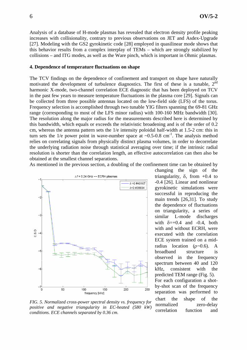
Analysis of a database of H-mode plasmas has revealed that electron density profile peaking increases with collisionality, contrary to previous observations on JET and Asdex-Upgrade [27]. Modeling with the GS2 gyrokinetic code [28] employed in quasilinear mode shows that this behavior results from a complex interplay of TEMs – which are strongly stabilized by collisions – and ITG modes, as well as the Ware pinch, which is important in Ohmic plasmas. 4. Dependence of temperature fluctuations on shape The TCV findings on the dependence of confinement and transport on shape have naturally motivated the development of turbulence diagnostics. The first of these is a tunable, 2nd harmonic X-mode, two-channel correlation ECE diagnostic that has been deployed on TCV in the past few years to measure temperature fluctuations in the plasma core [29]. Signals can be collected from three possible antennas located on the low-field side (LFS) of the torus. Frequency selection is accomplished through two tunable YIG filters spanning the 69-81 GHz range (corresponding to most of the LFS minor radius) with 100-160 MHz bandwidth [30]. The resolution along the major radius for the measurements described here is determined by this bandwidth, which equals or exceeds the relativistic broadening and is of the order of 0.2 cm, whereas the antenna pattern sets the 1/e intensity poloidal half-width at 1.5-2 cm: this in turn sets the 1/e power point in wave-number space at ~0.5-0.8 cm-1. The analysis method relies on correlating signals from physically distinct plasma volumes, in order to decorrelate the underlying radiation noise through statistical averaging over time; if the intrinsic radial resolution is shorter than the correlation length, an effective autocorrelation can then also be obtained at the smallest channel separations.
icted TEM range (Fig. 5).
As mentioned in the previous section, a doubling of the confinement time can be obtained by changing the sign of the triangularity, δ, from +0.4 to -0.4 [26]. Linear and nonlinear gyrokinetic simulations were successful in reproducing the main trends [26,31]. To study the dependence of fluctuations on triangularity, a series of similar L-mode discharges with δ=+0.4 and -0.4, both with and without ECRH, were executed with the correlation ECE system trained on a mid-radius location (ρ~0.6). A broadband structure is observed in the frequency spectrum between 40 and 120 kHz, consistent with the predFor each configuration a shot-by-shot scan of the frequency separation was performed to chart the shape of the normalized zero-delay correlation function and
FIG. 5. Normalized cross-power spectral density vs. frequency forpositive and negative triangularity in EC-heated (580 kW)conditions. ECE channels separated by 0.36 cm.

7 OV/5-2
determine the radial correlation length. The correlation function is calculated by integration over the relevant frequency range (20-80 kHz), mainly to avoid pollution by low-frequency MHD phenomena. One may then attempt to determine the correlation length by fitting an exponential function to the radial dependence. This parameter can be seen as the size of the random step in turbulent diffusivity and is thus an indirect indicator of transport. A comparison between positive and negative triangularity, for equal separation (0.36 cm), shows that the correlation function is larger for the former (Fig. 5), suggesting a higher fluctuation level or a longer correlation length, or both, consistent with confinement degradation with triangularity [32]. A correlation length has been derived thus far however only for positive triangularity as insufficient statistics have been obtained in the negative triangularity case. Longer integration times may alleviate this difficulty in the future. The plasma is optically gray for these ECE frequencies at this location (optical thickness τ~2-3), which causes the measured radiative temperature to be influenced by both temperature and density fluctuations. However, the shape dependence is theoretically calculated to be similar for the two quantities. 5. Spontaneous plasma rotation and relation with MHD and turbulence
providing a refinement in the
FIG. 6. Toroidal rotation profiles of carbonimpurities for a sequence of discharges at varyingcurrents, in (a) limited and (b) divertedconfigurations. (Negative = co-current.)
(a)
(b)
Toroidal momentum injection in TCV is negligible, as its only source is a diagnostic neutral beam injector (DNBI) delivering less than 80 kW to the plasma and inducing a maximum toroidal rotation speed of 1 km/s. Spontaneous toroidal momentum generation is nonetheless systematically observed [33-35], with strong dependences of the magnitude and sign on density, on the boundary topology (limited or diverted), and on the plasma current. The recent upgrades to the CXRS system have confirmed the basic phenomenology while
measurements. A particularly striking event is the rotation inversion that was observed in the core from the counter- to the co-current direction in limited plasmas when density is increased and when the edge safety factor is close to 3; an opposite inversion from counter- to co-rotation was seen in diverted configurations in a somewhat broader current range [34]. As a corollary, the formation of a divertor was therefore generally reported to be accompanied by rotation inversion. In view of the frequent appearance of MHD modes in these scenarios, a dedicated effort has now been devoted to elucidating the role of MHD activity in the rotation inversion. As a

8 OV/5-2
from counter- to slightly co-current [36].
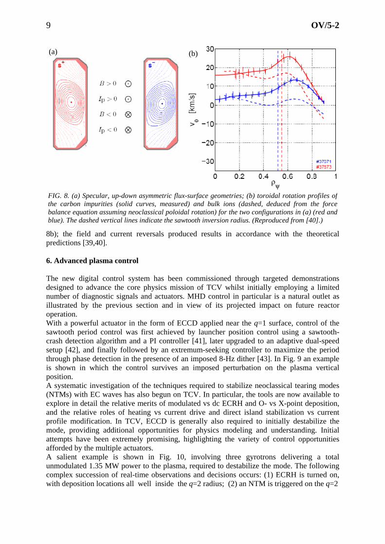
general result, core tearing modes with low rational mode numbers (m/n=2/1, 3/2) are found to strongly influence the toroidal rotation velocity profile, flattening the gradient and even reversing its signAmongst MHD-related phenomena, sawtooth relaxations appear to be the key player in angular momentum transport, as suggested by a systematic exploration of the dependence of the rotation inversion phenomenon on the safety factor. The average toroidal rotation velocity profile is flat or slightly hollow inside the mixing radius. As the latter moves closer to the edge when current rises, the value of the rotation velocity there gradually approaches the value at the edge. As a result, the core rotation varies continuously and can also change direction (Fig. 6) [36]. Through current control, the inversion has now been seen in a broad range of densities. It is also hypothesized that the differences between the limited and diverted topologies may be ascribed primarily to the effect on MHD of the underlying differences in shape. Indeed, the rotation inversion at the divertor formation can be prevented by appropriately tailoring the q profile evolution. The sawteeth can be sensitively affected by core ECCD, and flattening or peaking of the rotation velocity profile have accordingly been demonstrated by the application of co- or counter-ECCD, respectively. The natural next step is to study the evolution of the rotation profile during the sawtooth cycle itself. To this end, sawteeth were lengthened by the application of ECCD near the q=1 surface, in a configuration known to stabilize the internal kink mode. Coherent averaging over multiple sawteeth was then employed to improve statistics. The rotation profile is seen to peak sharply, i.e., the plasma spins up rapidly in the co-current direction on axis, just after the crash (Fig. 7); a rapid and complete relaxation to the pre-crash profile ensues in a time much shorter than the sawtooth period [35]. Initial attempts to explain this phenomenology with a heuristic model invoking the generation of a strong electric field during reconnection have been met with partial success, but more detailed measurements are required and planned. The question of the generation of spontaneous rotation is inextricably linked to that of momentum transport, and particularly turbulent transport, which is thought to play a major role. However, a breaking of the field-line symmetry around the LFS midplane is required for net flux-surface-averaged radial flux [37], and this severely constrains the candidate mechanisms. One new such mechanism that has recently been predicted relies on up-down plasma asymmetry [38] and has been recently put to the test on the TCV tokamak, whose extreme shaping capabilities are uniquely suited to this scenario. Indeed, the shapes were
devised to maximize the effect by extending the asymmetry to much of the plasma cross section (Fig. 8a). As the flux is predicted to change sign with either the magnetic field or the plasma current, two specular shapes were created with both signs of each quantity. The intrinsic toroidal rotation speed was indeed observed to change by a factor of two between the two shapes, most of the difference in the gradient being localized in the more
asymmetric edge region (Fig. FIG. 7. Radial profiles of the change in toroidal rotation at the sawtooth crash for several discharges with similar q profiles.
9 OV/5-2
theoretical redictions [39,40].
. Advanced plasma control
y the previous section and in view of its projected impact on future reactor
in which the control survives an imposed perturbation on the plasma vertical
mising, highlighting the variety of control opportunities
ith deposition locations all well inside the q=2 radius; (2) an NTM is triggered on the q=2
8b); the field and current reversals produced results in accordance with thep 6 The new digital control system has been commissioned through targeted demonstrations designed to advance the core physics mission of TCV whilst initially employing a limited number of diagnostic signals and actuators. MHD control in particular is a natural outlet as illustrated boperation. With a powerful actuator in the form of ECCD applied near the q=1 surface, control of the sawtooth period control was first achieved by launcher position control using a sawtooth-crash detection algorithm and a PI controller [41], later upgraded to an adaptive dual-speed setup [42], and finally followed by an extremum-seeking controller to maximize the period through phase detection in the presence of an imposed 8-Hz dither [43]. In Fig. 9 an example is shown position. A systematic investigation of the techniques required to stabilize neoclassical tearing modes (NTMs) with EC waves has also begun on TCV. In particular, the tools are now available to explore in detail the relative merits of modulated vs dc ECRH and O- vs X-point deposition, and the relative roles of heating vs current drive and direct island stabilization vs current profile modification. In TCV, ECCD is generally also required to initially destabilize the mode, providing additional opportunities for physics modeling and understanding. Initial attempts have been extremely proafforded by the multiple actuators. A salient example is shown in Fig. 10, involving three gyrotrons delivering a total unmodulated 1.35 MW power to the plasma, required to destabilize the mode. The following complex succession of real-time observations and decisions occurs: (1) ECRH is turned on, w
FIG. 8. (a) Specular, up-down asymmetric flux-surface geometries; (b) toroidal rotation profiles ofthe carbon impurities (solid curves, measured) and bulk ions (dashed, deduced from the forcebalance equation assuming neoclassical poloidal rotation) for the two configurations in (a) (red andblue). The dashed vertical lines indicate the sawtooth inversion radius. (Reproduced from [40].)
(a) (b)

10 OV/5-2
FIG. 9. Maximization of the sawtooth period. (Reproduced from [43].)
1 2 3 4
5 6
FIG. 10. Top: power traces for two ECRH clusters (solid curves), corresponding depositionlocations (dashed); bottom: spectrogram of a Mirnov coil signal, superimposed on a line-integratedsoft X-ray trace (black solid curve, a.u.), A m/n=2/1 NTM is visible as a red band in the 6-10 kHzfrequency range, and a 4/2 harmonic is seen at twice that frequency.
11 OV/5-2
eting.
surface; (3) the system responds by turning off one gyrotron and moving the associated launcher to a deposition location well outside the island – the mode, being metastable at this power, remains; (4) the power on this gyrotron is turned back on and its deposition location is moved slowly inward, until it reaches the q=2 surface and (5) the mode is stabilized; (6) the system responds by holding the launcher position steady until the end of the discharge, and no further destabilization is observed [36]. A clear separation is established in this sequence between the mode destabilization related to heating and global current-profile modification, and its stabilization by direct island targWe have also performed successful initial experiments in kinetic profile tailoring. The peak amplitude and width of a profile of line-integrated soft-X-ray signals were controlled by means of two EC sources directed centrally and at mid-radius, respectively. A linear-quadratic-Gaussian controller was constructed using a system-identification algorithm based on the response to random binary modulation of the EC powers [43]. More recently, a simple β observer was also developed and implemented, again through control of the ECRH power. Control algorithms are constantly being developed for the practical purpose of facilitating operations or enhancing the capabilities of heating or diagnostic subsystems: examples include Ohmic transformer clamping for fully noninductive operation, control of the X3 launcher angle for maximum absorption, and event-based diagnostic triggering. Envisioned future applications include in particular enhanced breakdown control in standard or exploratory scenarios [44,45]. To this end, a model has been developed to derive the magnetic configuration inside the vessel at breakdown time from a set of magnetic measurements. The model has been validated by visible light emission measurements, which show that the initial ionization phase is localized to the region in which the calculated connection length is maximum. The ramp-up phase is modeled instead by a simple single-filament representation of the plasma current. A statistical analysis of a large number of TCV shots, assisted by these models, has also been carried out to characterize the conditions for successful breakdown [44]. Finally, a systematic exploration of ECRH-assisted breakdown has begun in the last campaign. 7. Conclusions and outlook The TCV facility remains strongly engaged in its dual mission of probing the physics issues raised by the ITER project and casting a wider net in order to prepare for future concepts in magnetic fusion. This mission is especially supported by the steady enhancements and additions to the diagnostic and control tools and by the educational vocation of the laboratory, featuring a strong student presence in tokamak exploitation. The two years of research summarized by this paper have seen significant advances in all primary areas of exploration: the first experimental realization of the novel snowflake divertor topology, including the sustainment of a stable ELMy H-mode; the systematic study of the role of the current profile in electron energy transport and of the transport of carbon impurities in TEM-dominated regimes; the first study of the dependence of turbulence on the sign of the triangularity; the experimental verification of a newly predicted mechanism for turbulent momentum transport; and a budding and rapidly expanding program of nonlinear digital control of a uniquely flexible and versatile magnetic-coil and electron-cyclotron heating complement. Our future outlook envisions a greater diversification through a series of major upgrades, which include neutral-beam heating (up to 3 MW) [46], 3 MW additional X3 power, and a complete refurbishment of the low-field-side plasma-facing components for improved power handling. This will allow the extension of our shaping investigations to high-power scenarios, in particular to study H-mode physics in negative triangularity configurations. A set of in-
12 OV/5-2
vessel saddle coils to generate resonant magnetic perturbations for error-field correction and ELM control would also be installed at this time [47]. These upgrades are proposed to be phased in during the next six years and thus to be fully implemented well before the start of ITER operation. References [1] F. Hofmann et al, Plasma Phys. Control. Fusion 36 (1994) B277. [2] ITER Technical Basis, ITER EDA Documentation Series No 24, IAEA, Vienna (2002). [3] J. Pamela et al, Fusion Eng. and Design 84 (2009) 194. [4] T.P. Goodman and the TCV Team, Nucl. Fusion 48 (2008) 054011. [5] J.B. Lister et al, Fusion Sci. Technol. 32 (1997) 321. [6] A. Fasoli for the TCV Team, Nucl. Fusion 49 (2009) 104005. [7] A. Marinoni et al, Rev. Sci. Instrum. 77 (2006) 10E929. [8] S. Gnesin et al, Rev. Sci. Instrum. 79 (2008) 10F504. [9] J.I. Paley et al, Proc. 17th IEEE Real Time Conference, Lisboa, Portugal (2010). [10] N. Cruz et al, Proc. 17th IEEE Real Time Conference, Lisboa, Portugal (2010). [11] D.D. Ryutov, Phys. Plasmas 14 (2007) 064502. [12] D.D. Ryutov et al, Phys. Plasmas 15 (2008) 092501. [13] F. Piras et al, Plasma Phys. Control. Fusion 51 (2009) 055009. [14] F. Piras et al, Phys. Rev. Lett. 105 (2010) 155003. [15] F. Piras et al, to be published in Plasma Phys. Control. Fusion (2010). [16] Y.R. Martin et al, J. Phys.: Conf. Ser. 123 (2008) 012033. [17] J. Marki et al, J. Nucl. Mater. 390-391 (2009) 801. [18] G. Veres et al, J. Nucl. Mater. 390-391 (2009) 835. [19] C. Zucca et al, Plasma Phys. Control. Fusion 51 (2009) 125009. [20] P.H. Rebut et al, Proc. 12th Int. Conf. on Plasma Physics and Controlled Nuclear Fusion Research, Nice,
1988, vol. 2, p. 191, IAEA, Vienna (1989). [21] M.A. Henderson et al, Phys. Rev. Lett. 93 (2004) 215001. [22] T.P. Goodman et al, Plasma Phys. Control. Fusion 47 (2005) B107. [23] C. Zucca et al, Plasma Phys. Control. Fusion 51 (2009) 015002. [24] E. Fable et al, Plasma Phys. Control. Fusion 52 (2010) 015007. [25] Y. Martin et al, EXC/P8-13, this conference. [26] Y. Camenen et al, Nucl. Fusion 47 (2007) 510. [27] D. Wágner et al, Proc. 37th EPS Conf. on Control. Fusion and Plasma Phys., Dublin, 2010. [28] M. Kotschenreuther et al, Comput. Phys. Commun. 88 (1995) 128. [29] V.S. Udintsev et al, Fusion Sci. Technol. 52 (2007) 161. [30] T.P. Goodman, Proc. 16th Joint Workshop on Electron Cyclotron Emission and Electron Cyclotron
Resonance Heating (EC-16), Sanya, China (2010). [31] A. Marinoni et al, Plasma Phys. Control. Fusion 51 (2009) 055016. [32] B. Labit et al, EXC/P8-08, this conference. [33] A. Bortolon et al, Phys. Rev. Lett. 97 (2006) 235003. [34] B.P. Duval et al, Phys. Plasmas 15 (2008) 056113. [35] B.P. Duval et al, EXS/P4-01, this conference. [36] O. Sauter et al, EXS/P2-17, this conference. [37] A.G. Peeters et al, Phys. Plasmas 12 (2005) 072515. [38] Y. Camenen et al, Phys. Rev. Lett. 102 (2009) 125001. [39] Y. Camenen et al, Phys. Rev. Lett. 105 (2010) 135003. [40] Y. Camenen et al, to be published in Plasma Phys. Control. Fusion (2010). [41] J.I. Paley et al, Nucl. Fusion 49 (2009) 085017. [42] J.I. Paley et al, Plasma Phys. Control. Fusion 51 (2009) 055010. [43] J.I. Paley et al, Plasma Phys. Control. Fusion 51 (2009) 124041. [44] F. Piras et al, Proc. 37th EPS Conf. on Control. Fusion and Plasma Phys., Dublin, 2010. [45] F. Piras et al, Fusion Eng. and Design 85 (2010) 739. [46] A.N. Karpushov et al, Proc. 26th Symposium on Fusion Technology (SOFT-2010), Porto, Portugal
(2010). [47] J.X. Rossel et al, Plasma Phys. Control. Fusion 52 (2010) 035006.


![Overview of Physics Research on the TCV Tokamak · discusses evidence for discharges that are fully sustained in steady-state by the bootstrap current [5]; Section 3 focuses on the](https://static.fdocuments.in/doc/165x107/606f76170431af2ee01dbccd/overview-of-physics-research-on-the-tcv-tokamak-discusses-evidence-for-discharges.jpg)