Outload Trough Roller Conveyor - crustbuster.com Operator Qualifications Operation of this conveyor...
26
Outload Trough Roller Conveyor OWNER'S MANUAL 00003400 (8/99)
Transcript of Outload Trough Roller Conveyor - crustbuster.com Operator Qualifications Operation of this conveyor...

Outload Trough Roller
Conveyor
OWNER'S MANUAL
00003400 (8/99)

Table of Contents
Warranty Information . . . . . . . . . . . . . . . . . . . . . . . . . . . . . . Inside Front CoverOperator Qualifications / Sign Off Sheet . . . . . . . . . . . . . . . . . . . . . . . . . . . . . . 1Safety Instructions . . . . . . . . . . . . . . . . . . . . . . . . . . . . . . . . . . . . . . . . . . . . 2-3Specifications . . . . . . . . . . . . . . . . . . . . . . . . . . . . . . . . . . . . . . . . . . . . . . . . . 4General Maintenance & Operation . . . . . . . . . . . . . . . . . . . . . . . . . . . . . . . . 5-6Stand Support Locations . . . . . . . . . . . . . . . . . . . . . . . . . . . . . . . . . . . . . . . . . . 7Dimensional Drawing . . . . . . . . . . . . . . . . . . . . . . . . . . . . . . . . . . . . . . . . . . 8-9
Repair Parts:Head . . . . . . . . . . . . . . . . . . . . . . . . . . . . . . . . . . . . . . . . . . . . . . . . 10Tail . . . . . . . . . . . . . . . . . . . . . . . . . . . . . . . . . . . . . . . . . . . . . . . . 11Pans . . . . . . . . . . . . . . . . . . . . . . . . . . . . . . . . . . . . . . . . . . . . . . . . . . 12-13Support Stands . . . . . . . . . . . . . . . . . . . . . . . . . . . . . . . . . . . . . . . . . . 14-17Telescoping Spout . . . . . . . . . . . . . . . . . . . . . . . . . . . . . . . . . . . . . . . . . . 18
Assembly Instructions . . . . . . . . . . . . . . . . . . . . . . . . . . . . . . . . . . . . . . . . 19-22
WarrantyCrustBuster/Speed King, Inc. of Dodge City, Kansas, warrants consumer products, sofar as the same is of our own manufacture, against defects in material andworkmanship under normal and reasonable use for a period of one (1) year after dateof delivery to the original purchaser. Our obligation under this warranty is limited,however, to furnishing a replacement part for a defective part, or at our option to repairthe defective parts without charge, either method F.O.B. our works, provided theconsumer gives CrustBuster/Speed King,Inc. written notice within ten (10) days aftersaid part appears to be defective and affords CrustBuster/Speed King,Inc. anopportunity to inspect. Unless otherwise expressly agreed to by CrustBuster/SpeedKing,Inc., the consumer shall bear the expense of installation.
CrustBuster/Speed King, Inc. will not be liable for consequential damages where theloss is commercial, including but not limited to loss of profit, delays or expenses.
This warranty sets forth the extent of our liability. The foregoing is in lieu of all otherwarranties, expressed or implied, including any warranties that extend beyond thedescription of the product.

1
Operator Qualifications
Operation of this conveyor shall be limited to competent and experienced persons. In addition, anyonewho will operate or work around a conveyor must use good common sense. In order to be qualified,he or she must also know and meet all other requirements, such as:
1. Some regulations specify that no one under the age of 16 may operate powermachinery. It is your responsibility to know what these regulations are in your area orsituation.
2. Current OSHA regulations state in part: "At the time of initial assignment and at leastannually thereafter the employer shall instruct EVERY employee in the safe operationof servicing of all equipment with which the employer is, or will be involved."
3. Unqualified persons are to STAY OUT of the work area.
4. A person who has not read and understood all operating and safety instructions is notqualified to operate the machinery.
FAILURE TO READ THIS CONVEYOR MANUALAND ITS SAFETY INSTRUCTIONS IS A MISUSEOF THE EQUIPMENT.
Sign Off Sheet
As a requirement of OSHA, it is necessary for the employer to train the employee in the safe operationand safety procedures with this Trough Roller. We include this sign off sheet for your convenience andpersonal record keeping.
DATE EMPLOYER EMPLOYER'S SIGNATURE

2
BE ALERT! Your Safety is involved.
General Safety StatementWATCH FOR THIS SYMBOL. IT POINTS OUT IMPORTANTSAFETY PRECAUTIONS. IT MEANS "ATTENTION ������������BECOME ALERT!" YOUR SAFETY IS INVOLVED.
It is your responsibility as an owner, operator, or supervisor to know and instruct everyone using thisconveyor at the time of initial assignment and at least annually thereafter, of the proper operation,precautions, and work hazards which exist in the operation of this conveyor in accordance with OSHARegulations.
Safety Is No AccidentThe following safety instructions, combined with common sense, will save your equipment fromneedless damage and the operator from unnecessary exposure to personal hazard. Pay specialattention to the caution notes in the text. Review this manual at least once each year with new and/orexperienced operators.
1. Read and understand the operator's manual before operating this conveyor. Failureto do so is considered a misuse of the equipment.
2. Make sure conveyor is secure before operating.
3. Always keep children away from conveyor when operating.
4. The motor controls and reset button must be located so that the operator has a fullview of the entire operation.
5. During regular operation of the conveyor, one person should be in a position tomonitor the operation. A second person should always be nearby to shutdown theconveyor in case of an emergency.
6. Make sure everyone that is not directly involved with the operation is out of the workarea before beginning the operation.
7. Keep the work area clear of grease, oil, water, and other objects that could causea slip or a fall.
8. Make sure all safety devices, shields, and guards are in place and are functionalbefore beginning the operation.

3
9. Shut off and lock out power to adjust, service, or clean the conveyor.
10. Keep hands, feet, and clothing away from moving parts. It is a good idea to removeall jewelry before starting the operation.
11. Visually inspect the conveyor periodically during operation for signs of excessivevibration, loose fasteners, and unusual noises.
Electric Safety1. Electric motors and controls should be wired by a qualified electrician and meet all
standards set by Federal, State, and Local Electrical Codes.
2. Make certain electric motors are grounded.
3. A magnetic starter should be used to protect your motor.
4. Your motor must have a manual reset button.
5. Electrical power must be disconnected before resetting your motor.
6. A main power disconnect switch, with the ability to be locked in the off position,should be provided. The switch should be locked in the off position whenever workis to be done on the conveyor or the conveyor is going to be left unattended.
7. Disconnect power before resetting motor overload.
CAUTION1. Read and understand instruction manual before operating.
2. Keep all safety shields and devices in place.
3. Make certain everyone is clear before operating machine.
4. Keep hands, feet, and clothing away from moving parts.
5. Shut off power to adjust, service, or clean.
6. Make sure machine is secured before operating.
7. Disconnect power before resetting motor overload.
8. Make certain electric motors are grounded.

4
Outload Conveyor Specifications
16" - 24"Length: 25' through 43';
45' available in 24"
Belting: 16" or 24" wide PVC Chevron cover design
Belt Speed: 600 FPM
Conveyor Sections: 304 stainless steel construction2 3/8" dia. PVC return rollers2" dia PVC carrier rollers
Head Drive Terminal: 10 ga. 304 stainless steel construction6" lagged drive roller1 5/16" drive shaftRegreasable flange mount ball bearings18.4" drive sheave4.2" motor sheave
Tail Take-up Terminal: 304 stainless steel construction3 1/2" tail roller1 5/16" tail shaftRegreasable pillow block ball bearingStainless steel hopperGrease packed take-up slides
Weather Covers 304 stainless steel construction
Power Requirements 1800 RPM, 3-phase, 60 Hz, TEFC electric motor16" 25' to 26' 5 Hp
27' to 42' 7½ Hp
24" 25' to 36' 7½ Hp36' to 45' 10 Hp
Electric Motor Specifications 1. All electric motors to be 1800 RPM TEFC unless otherwise specified by the manufacturer.
General MaintenancePreventive maintenance is the key to the long life of any mechanical device. Careful andsystematic inspection of all trough roller conveyor equipment will assure maximum trouble freeservice.
Correct belt tension and alignment are extremely important. Maintaining proper adjustments canadd many hours of extra belt life.

5
Lubrication
1. All bearings which are fitted with grease zerks should be lubricated daily during heavy use.Before greasing the bearings, make certain the zerks are free of dirt. Otherwise, this will bepassed into the bearing race. If the unit will be out of service for a period of time, purge thebearings.
2. Electric motors should be oiled in accordance with the manufacturer's recommendations.
Pre-Operation Check List1. Check all bearings for proper lubrication.2. Check conveyor for foreign material or obstruction.3. Check all V-belts for proper tension.4. Start conveyor and check belt alignment while unit is empty.
Operation Sequence1. For each installation, placement of each conveyor will dictate the operation sequence. Normally,
the last conveyor the material is transfered to, should be started first.
Conveyor Belt Length Formula1st ��� Double the total length of trough sections. ' - " Belt
2nd ��� For 1' Take-up and 2' Head Drive add 4' - 4" Belt
Conveyor Belt Take-upAfter extended use, the conveyor belt may stretch to the extent that there is not sufficient take-up fortensioning. Addditional take-up may be obtained by cutting an 8" section from the belt and re-splicing.Splice kits may be obtained locally or ordered from the factory using the part numbers below.
#63055800 - 16" Belt Splice Kit#63056600 - 24" Belt Splice Kit
Conveyor Belt ReplacementTo replace the conveyor belt, pull out the splice pin and splice one end of the new belt to one end ofthe old belt. Pull the new belt in as you pull the old belt out. After you have run this unit and alignedthe new belt, seal the splice with the belt splice rubber compound and let cure in accordance withinstructions on container.
Conveyor Belt StorageIf unit is to be out of service for a month or longer, relieve tension from belt and clean off all materialbuild-up.
1. Before attempting to train the belt, check all pulley and idler bearings. They should be locatedin the center of their slots, level, and at a 90° angle to the direction of the belt travel.
2. Slight adjustment of pulleys may be required to keep belt centered on them. i.e.-If the conveyorbelt runs to one side of the pulley, apply more tension to the opposite side or release a littletension on the side of the pulley the belt is running to.

6
Conveyor Belt Tension / Alignment
PRIOR TO START-UP, CHECK TO SEE THAT THEBELT IS FREE FROM ANY OBJECTS THAT WOULDBIND OR TEAR THIS BELT.
1. When starting for the first time with no load on the belt, apply power for a few seconds only tosee that the conveyor belt travels in the proper direction and is well centered in the trough.
2. The belt is tensioned by adjusting the take-up bolts located at the "TAIL". The belt should betensioned tight enough so the drive pulley does not slip when the conveyor is running "underload", or when the conveyor is started "under load".
3. It should be noted that too much tension on the conveyor belt will make alignment / trainingmore difficult, shorten the life of the belt, and waste power. Re-adjust the tension after theconveyor is running "under load".
Conveyor Belt Alignment / Training
1. Before attempting totrain the belt, check allpulley and idlerbearings. Theyshould be located inthe center of theirslots, level, and at a90° angle to thedirection of the belttravel.
2. Slight adjustment ofpul leys may berequired to keep beltcentered on them. i.e.-If the conveyor beltruns to one side of thepulley, apply moret e n s i o n t o t h eopposite side orrelease a little tensionon the side of thepulley the belt isrunning to.

7
Outload ConveyorStand Support Locations
25' - 42'
45' Only

8
Outload ConveyorDimensional Drawing(25° Incline)

9
Outload ConveyorDimensional Drawing
(25° Incline)
Conveyor Mid SectionLengths Lengths A B
25' (2)- 10' (1)- 3' 9'- 11" 22'- 6½"26' (2)- 10' (1)- 4' 10'- 4" 23'- 5¼"27' (2)- 10' (1)- 5' 10'- 9" 24'- 4"28' (2)- 10' (1)- 6' 11'- 2" 25'- 3"29' (2)- 10' (1)- 7' 11'- 7¼" 26'- 2"
30' (2)- 10' (2)- 4' 12'- ¼" 27'- ½"31' (2)- 10' (1)- 5' (1)- 4' 12'- 5¼" 27'- 11"32' (3)- 10' 12'-11½" 28'-10½"33' (2)- 10' (1)- 6' (1)- 5' 13'- 3½" 29'- 9¼"34' (2)- 10' (1)- 7' (1)- 5' 13'- 8½" 30'- 8"
35' (3)- 10' (1)- 3' 14'- 1½" 31'- 7"36' (3)- 10' (1)- 4' 14'- 6½" 32'- 6"37' (3)- 10' (1)- 5' 14'-11¾" 33'- 4¼"38' (3)- 10' (1)- 6' 15'- 4¾" 34'- 3½"39' (3)- 10' (1)- 7' 15'- 9¾" 35'- 2½"
40' (3)- 10' (2)- 4' 16'- 6" 36'- 1¼"41' (3)- 10' (1)- 5' (1)- 4' 16'- 8" 37'- 0"42' (4)- 10' 17'- 1" 37'- 11"43' (3)- 10' (1)- 6' (1)- 5' 17'- 6" 38'- 10"
45' (4)- 10' (1)- 3' 18' 4" 40'- 7½"

10
Outload ConveyorHead Repair Parts
16" Outload Conveyor
Item Qty Part No. Description1 1 83166900 Spout Weldment2 1 88826300 Lagged Roller 6" 2 A 1 16088700 Shaft 1 5/16" x 27 1/2"3 2 03018900 Bearing 1 5/16" 2B Fl4 1 83928200 Head Frame5 1 60000700 Motor Mount
Item Qty Part No. Description6 2 03544400 V-Belt B- 737 1 04285300 Sheave 2B 18.4 SK8 1 83180000 Guard End Cover9 3 16801300 Guard Bracket
10 1 18624700 Guard
24" Outload Conveyor
Item Qty Part No. Description1 1 61514600 Spout Weldment2 1 81534000 Lagged Roller 6" w/shaft3 2 03018900 Bearing 1 5/16" 2B Fl4 1 83914200 Head Frame5 1 60000700 Motor Mount
Item Qty Part No. Description6 2 03544400 V-Belt B- 737 1 04285300 Sheave 2B 18.4 SK8 1 83180000 Guard End Cover9 3 16801300 Guard Bracket
10 1 18624700 Guard

11
Outload ConveyorTail Repair Parts
16" Outload Conveyor
Item Qty Part No. Description1 1 60560000 Lagged Roller 3 1/2"
w/shaft2 2 03033800 Bearing 1 5/16" PB3 2 600346 Zerk 1/4"-28 x 17/32"4 1 81679300 Take-up Tube5 1 15636400 Take-up Base6 1 81680100 Take-up Bracket LH7 1 81681900 Take-up Bracket RH8 2 01370600 Square Nut 3/4"-109 2 18622100 Guide Strap
Item Qty Part No. Description10 2 18656900 Guide Skirtboard11 2 16092900 Back-up Strap12 1 83929000 Hopper Weldment13 1 18655100 Hopper Wiper14 1 18623900 Hopper Wiper Strap15 2 16116600 Wear Plate16 4 01409200 Screw #10-24 x ½" Slotted
Flat Machine SS17 4 01052000 Hex Nut #10-24 SS
24" Outload ConveyorItem Qty Part No. Description
1 1 60355500 Lagged Roller 3 1/2"2 2 03033800 Bearing 1 5/16" PB3 2 600346 Zerk 1/4"-28 x 17/32"4 1 81679300 Take-up Tube5 1 15637200 Take-up Base6 1 81680100 Take-up Bracket LH7 1 81681900 Take-up Bracket RH8 2 01370600 Square Nut 3/4"-109 2 18622100 Guide Strap
Item Qty Part No. Description10 2 18656900 Guide Skirtboard11 2 16092900 Back-up Strap12 1 83934000 Hopper Weldment13 1 18639500 Hopper Wiper14 1 18640300 Hopper Wiper Strap15 2 16116600 Wear Plate16 4 01409200 Screw #10-24 x ½" Slotted
Flat Machine SS17 4 01052000 Hex Nut #10-24 SS

12
16'' Pan Repair Parts
3' PanItem Qty Part No. Description
61142600 3'-16" Covered Pan Bundle61136800 3'-16" Pan Assembly
1 1 83950600 3'-16" Pan Weldment2 2 60191400 Roller 2 x 10³ 4 06874200 Roller Clip4 2 14206700 Spreader5 2 13019500 Roller Bracket6 1 60194800 Roller 2 3/8" x 16"7 1 18682500 3' Weather Cover8 1 10959500 4" Cover Strap
4' PanItem Qty Part No. Description
61143400 4'-16" Covered Pan Bundle61137600 4'-16" Pan Assembly
1 1 83951400 4'-16" Pan Weldment2 2 60191400 Roller 2 x 10³ 4 06874200 Roller Clip4 2 14206700 Spreader5 2 13019500 Roller Bracket6 1 60194800 Roller 2 3/8" x 16"7 1 18683300 4' Weather Cover8 1 10959500 4" Cover Strap
5' PanItem Qty Part No. Description
61124400 5'-16" Covered Pan Bundle61138400 5'-16" Pan Assembly
1 1 83931600 5'-16" Pan Weldment2 3 60191400 Roller 2 x 10³ 6 06874200 Roller Clip4 2 14206700 Spreader5 2 13019500 Roller Bracket6 1 60194800 Roller 2 3/8" x 16"7 1 18625400 5' Weather Cover8 1 10959500 4" Cover Strap
6' PanItem Qty Part No. Description
61144200 6'-16" Covered Pan Bundle61139200 6'-16" Pan Assembly
1 1 83952200 6'-16" Pan Weldment2 3 60191400 Roller 2 x 10³ 6 06874200 Roller Clip4 2 14206700 Spreader5 2 13019500 Roller Bracket6 1 60194800 Roller 2 3/8" x 16"7 1 18684100 6' Weather Cover8 1 10959500 4" Cover Strap
7' PanItem Qty Part No. Description
61145900 7'-16" Covered Pan Bundle61140000 7'-16" Pan Assembly
1 1 83953000 7'-16" Pan Weldment2 4 60191400 Roller 2 x 10³ 8 06874200 Roller Clip4 2 14206700 Spreader5 2 13019500 Roller Bracket6 1 60194800 Roller 2 3/8" x 16"7 1 18685800 7' Cover8 1 10959500 4" Cover Strap
10' PanItem Qty Part No. Description
61123600 10'-16" Covered Pan Bundle61141800 10'-16" Pan Assembly
1 1 83930800 10'-16" Pan Weldment2 5 60191400 Roller 2 x 10³ 10 06874200 Roller Clip4 2 14206700 Spreader5 2 13019500 Roller Bracket6 1 60194800 Roller 2 3/8" x 16"7 1 18626200 10' Weather Cover8 1 10959500 4" Cover Strap9 1 18628800 2" Cover Strap

13
24'' Pan Repair Parts
3' PanItem Qty Part No. Description
61150900 3'-24" Covered Pan Bundle61154100 3'-24" Pan Assembly
1 1 83955500 3'-24" Pan Weldment2 2 60192200 Roller 2 x 183 4 06874200 Roller Clip4 2 18631200 Spreader5 2 13019500 Roller Bracket6 1 60195500 Roller 2 3/8" x 24"7 1 18694000 3' Weather Cover8 1 10960300 4" Cover Strap
4' PanItem Qty Part No. Description
61151700 4'-24" Covered Pan Bundle61155800 4'-24" Pan Assembly
1 1 83956300 4'-24" Pan Weldment2 2 60192200 Roller 2 x 183 4 06874200 Roller Clip4 2 18631200 Spreader5 2 13019500 Roller Bracket6 1 60195500 Roller 2 3/8" x 24"7 1 18695700 4' Weather Cover8 1 10960300 4" Cover Strap
5' PanItem Qty Part No. Description
61132700 5'-24" Covered Pan Bundle61156600 5'-24" Pan Assembly
1 1 83933200 5'-24" Pan Weldment2 3 60192200 Roller 2 x 183 6 06874200 Roller Clip4 2 18631200 Spreader5 2 13019500 Roller Bracket6 1 60195500 Roller 2 3/8" x 24"7 1 18633800 5' Weather Cover8 1 10960300 4" Cover Strap
6' PanItem Qty Part No. Description
61152500 6'-24" Covered Pan Bundle61157400 6'-24" Pan Assembly
1 1 83957100 6'-24" Pan Weldment2 3 60192200 Roller 2 x 183 6 06874200 Roller Clip4 2 18631200 Spreader5 2 13019500 Roller Bracket6 1 60195500 Roller 2 3/8" x 24"7 1 18696500 6' Weather Cover8 1 10960300 4" Cover Strap
7' PanItem Qty Part No. Description
61153300 7'-24" Covered Pan Bundle61158200 7'-24" Pan Assembly
1 1 83958900 7'-24" Pan Weldment2 4 60192200 Roller 2 x 183 8 06874200 Roller Clip4 2 18631200 Spreader5 2 13019500 Roller Bracket6 1 60195500 Roller 2 3/8" x 24"7 1 18697300 7' Cover8 1 10960300 4" Cover Strap
10' Pan Item Qty Part No. Description
61131900 10'-24" Covered Pan Bundle61159000 10'-24" Pan Assembly
1 1 83932400 10'-24" Pan Weldment2 5 60192200 Roller 2 x 183 10 06874200 Roller Clip4 2 18631200 Spreader5 2 13019500 Roller Bracket6 1 60195500 Roller 2 3/8" x 24"7 1 18632000 10' Weather Cover8 1 10960300 4" Cover Strap9 1 18635300 2" Cover Strap
14
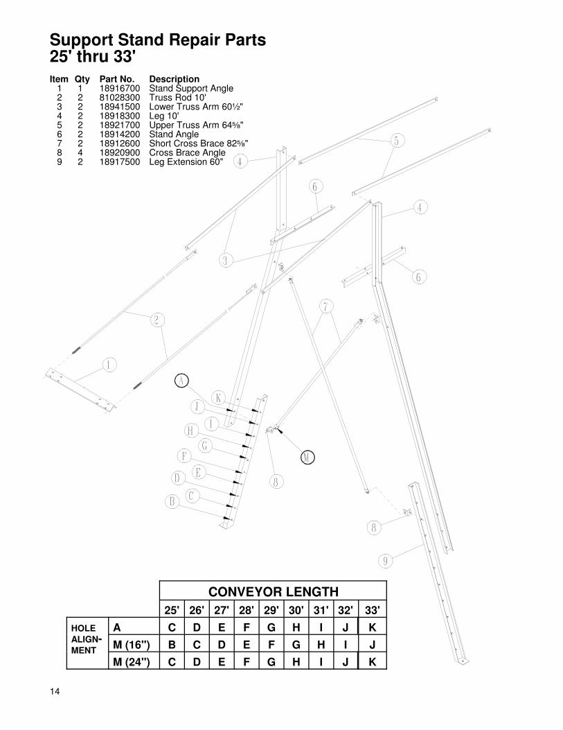
Support Stand Repair Parts25' thru 33'Item Qty Part No. Description
1 1 18916700 Stand Support Angle2 2 81028300 Truss Rod 10'3 2 18941500 Lower Truss Arm 60½"4 2 18918300 Leg 10'5 2 18921700 Upper Truss Arm 64�"6 2 18914200 Stand Angle7 2 18912600 Short Cross Brace 82�"8 4 18920900 Cross Brace Angle9 2 18917500 Leg Extension 60"
CONVEYOR LENGTH25' 26' 27' 28' 29' 30' 31' 32' 33'
HOLEALIGN-MENT
A C D E F G H I J KM (16") B C D E F G H I JM (24") C D E F G H I J K
15
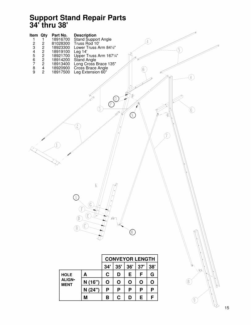
Support Stand Repair Parts34' thru 38'Item Qty Part No. Description
1 1 18916700 Stand Support Angle2 2 81028300 Truss Rod 10'3 2 18923300 Lower Truss Arm 84½"4 2 18919100 Leg 14'5 2 18921700 Upper Truss Arm 167¼"6 2 18914200 Stand Angle7 2 18913400 Long Cross Brace 135"8 4 18920900 Cross Brace Angle9 2 18917500 Leg Extension 60"
CONVEYOR LENGTH34' 35' 36' 37' 38'
HOLEALIGN-MENT
A C D E F GN (16") O O O O ON (24") P P P P PM B C D E F
16
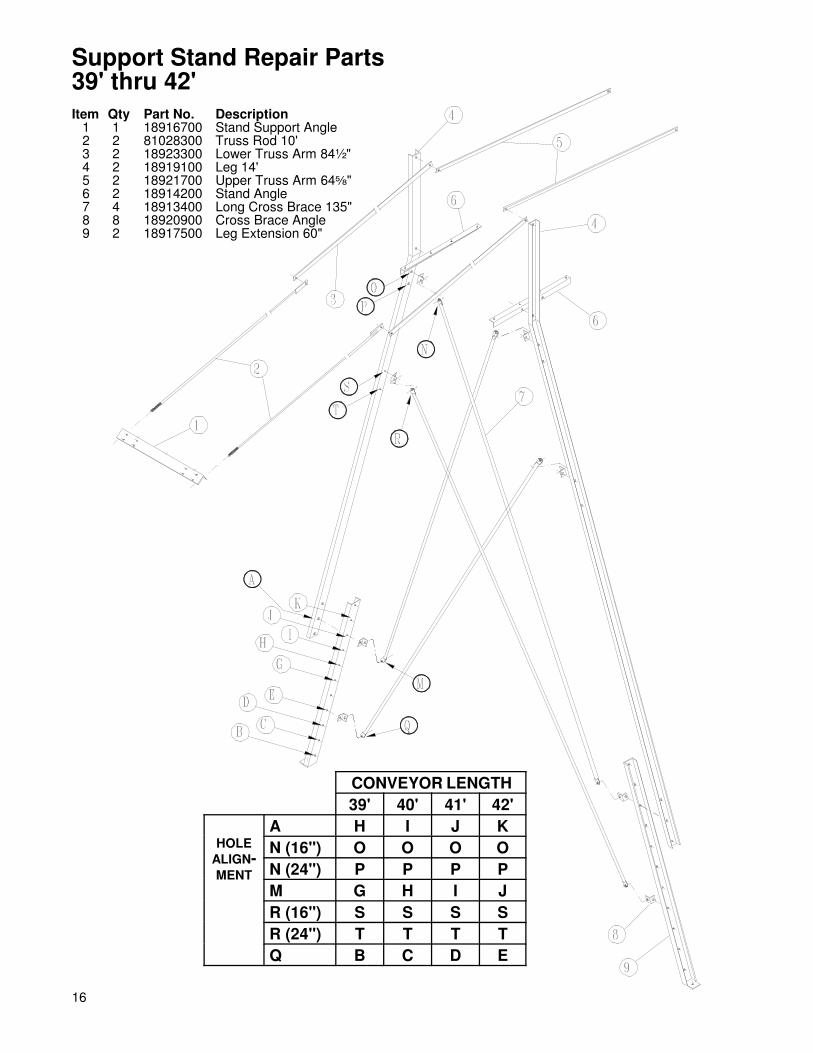
Support Stand Repair Parts39' thru 42'Item Qty Part No. Description
1 1 18916700 Stand Support Angle2 2 81028300 Truss Rod 10'3 2 18923300 Lower Truss Arm 84½"4 2 18919100 Leg 14'5 2 18921700 Upper Truss Arm 64�"6 2 18914200 Stand Angle7 4 18913400 Long Cross Brace 135"8 8 18920900 Cross Brace Angle9 2 18917500 Leg Extension 60"
CONVEYOR LENGTH39' 40' 41' 42'
HOLEALIGN-MENT
A H I J KN (16") O O O ON (24") P P P PM G H I JR (16") S S S SR (24") T T T TQ B C D E

17
Support Stand Repair Parts45' x 24"
Item Qty Part No. Description1 1 18916700 Stand Support Angle2 2 81028300 Truss Rod 10'3 2 12779500 Lower Truss Arm 88½"4 2 18919100 Leg 14'5 2 12778700 Upper Truss Arm 95"6 2 12777900 Stand Angle7 4 18913400 Long Cross Brace 135"8 8 18920900 Cross Brace Angle9 2 18917500 Leg Extension 60"
CONVEYORLENGTH
45'
HOLEALIGN-MENT
A KN PM GR TQ E

18
Item Qty Part No. Description1 1 81617300 Spout Weldment2 10 01549500 Hex Nut 3/8" SS3 2 333898 Eyebolt 3/8" x 2 ½"4 7 02143600 Cable Clamp 3/16"5 2 01463900 Swivel Pulley 1 ½"6 6 01245000 HHCS 1/4" x ½" SS7 10 337550 Lock Washer 1/4" SS8 10 01507300 Hex Nut 1/4" SS9 58 05115100 Cable 3/16"x7"x19"xFt
10 6 01134600 HHCS 3/8" x 1" SS11 6 02487700 Lock Washer 3/8" SS12 2 81870800 Winch Mount13 1 01985100 5" Vinyl Cap14 2 16510000 Cable Pulley Plate15 1 81869000 Cable Winch16 1 81871600 Winch Handle17 1 954024 Lock Pin18 4 02226900 HHCS 1/4" x 3/4" SS19 2 330407 Flat Washer 1"20 2 330662 Roll Pin 5/16" x 1 3/4"21 1 330860 Hair Pin22 2 02219400 Flat Washer 3/8" SS
Telescoping Spout Repair Parts

19
Outload ConveyorHead Assembly
Guard Bracket Locations
STEP #1 Assemble the head frame weldment "A"to the TR section "B" using hardware attached to thesection.
STEP #2 Attach the spout "C" to head frame "A"using five (5) 5/16" x 1" carriage bolts and hex nuts.(The hole and bolt shown in spout attaches to guardbracket in STEP #7.
STEP #3 Assemble electric motor to motor mount"C" using four (4) 3/8" x 1 3/4" stainless steel bolts,flat washers, and hex nuts. LEAVE THESEFASTENERS LOOSE.
STEP #4 Assemble sheave, bushing, and key "D"to the motor. Assemble sheave, bushing, and key "F"to the drive shaft. LEAVE THE SHEAVES ANDBUSHINGS LOOSE. Using a straight edge, align the
two (2) sheaves and secure the motor mount bolts andthe bushings.
STEP #5 Assemble the V-belts and tighten using themotor mount take-up bolt.
STEP #6 Assemble the belt guard end cap "G" tothe belt guard body "H" using four (4) 1/4" x 1/2"stainless steel bolts and four (4) 1/4" stainless steelhex nuts.
STEP #7 Using the "Belt Guard Bracket Location"diagram as a guide, attach the guard assembly to headframe using three (3) belt guard bIackets "I" and six(6) 5/16" x 1" stainless steel bolts, flat washers, andhex nuts.
STEP #8 Check for clearance between guard, belts,and sheaves before operating.
20
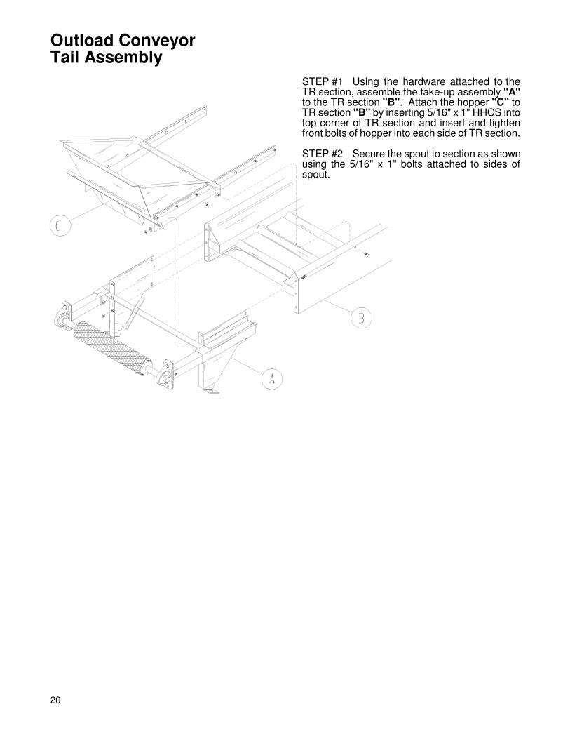
Outload ConveyorTail Assembly
STEP #1 Using the hardware attached to theTR section, assemble the take-up assembly "A"to the TR section "B". Attach the hopper "C" toTR section "B" by inserting 5/16" x 1" HHCS intotop corner of TR section and insert and tightenfront bolts of hopper into each side of TR section.
STEP #2 Secure the spout to section as shownusing the 5/16" x 1" bolts attached to sides ofspout.

21
Outload ConveyorStand Assembly(Suggested Assembly)
STEP #1 Refer to stand support locations onpages 14 - 17.Assemble angle "A" to conveyor and angle "B"to conveyor with 3/8" x 1" HHCS and nylocks.
STEP #2 Using 1/2" hardware, assemblechannel iron legs "C" to angle "B" looselyallowing legs to rotate into place as TR is lifted.
STEP #3 Attach leg "D" to leg "C" andremainder of trussing. Make sure all fastenersare tight and set. Anchor TR into place.

22
STEP #1 Starting at the tail or take-up end, install thefirst weather cover 1" up from the edge of the pansection. (Make sure dimple is UP.)
STEP #2 Where each pan section is bolted together,you will install a 4" weather cover strap. Simply slide thenext weather cover up against the one previouslyinstalled (Make sure dimples are correct) and fit thecover strap into place. Secure using four (4) 1/4" x 3/4"stainless steel carriage bolts, flat washers, and hexnuts.
STEP #3 Run a bead of silicone between the leadingedge of the weather cover strap and the "up" dimple.
Outload ConveyorWeather Cover Assembly

23

P.O.Box 1438 Dodge City, Kansas 67801 (620) 227-7106