OUTDOOR UNIT - Планета Климата · MSZ-FD•VA Series (OBH488) TECHNICAL CHANGES 2 1...
192
SERVICE MANUAL CONTENTS 1. TECHNICAL CHANGES ··································· 2 2. PART NAMES AND FUNCTIONS ····················· 8 3. INDOOR/OUTDOOR CORRESPONDENCE TABLE ························ 10 4. INDOOR UNITS COMBINATION ···················· 14 5. SPECIFICATION ·············································· 61 6. NOISE CRITERIA CURVES ···························· 66 7. OUTLINES AND DIMENSIONS ······················ 68 8. WIRING DIAGRAM·········································· 75 9. REFRIGERANT SYSTEM DIAGRAM ············· 87 10. PERFORMANCE CURVES ····························· 97 11. ACTUATOR CONTROL ··································115 12. SERVICE FUNCTIONS···································116 13. TROUBLESHOOTING ··································· 120 14. DISASSEMBLY INSTRUCTIONS ·················· 145 15. PARTS LIST··················································· 160 16. RoHS PARTS LIST ········································ 172 17. OPTIONAL PARTS ······················ BACK COVER Models MXZ-2A30VA - E1 MXZ-4A71VA - E2 MXZ-2A30VA - E2 MXZ-4A71VA - E3 MXZ-2A40VA - E1 MXZ-4A71VA - E4 MXZ-2A40VA - E2 MXZ-4A71VA - E5 MXZ-2A52VA - E1 MXZ-4A71VA - E6 MXZ-2A52VA - E2 MXZ-4A71VA - E7 MXZ-3A54VA - E1 MXZ-4A80VA - E1 MXZ-3A54VA - E2 MXZ-4A80VA - E2 MXZ-3A54VA - E3 MXZ-5A100VA - E1 MXZ-3A54VA - E4 MXZ-3A54VA - E5 MXZ-3A54VA - E6 MXZ-3A54VA - E7 MXZ-4A71VA - E1 No. OB377 REVISED EDITION-H HFC utilized R410A SPLIT-TYPE AIR CONDITIONERS MXZ-4A80VA- E1 Please void OB377 REVISED EDITION-G. OUTDOOR UNIT Revision H: • Indoor units combinations for 42 class have been added. • MXZ-3A54VA- E7 and MXZ-4A71VA- E7 have been added. NOTE: • RoHS compliant products have <G> mark on the spec name plate. For servicing of RoHS compliant products, refer to the RoHS Parts List. Indoor unit service manual MSZ-FA•VA Series (OB371) MSZ-GA•VA Series (OB378, OB388) MSZ-CB•VA Series (OB441) MSZ-GC•VA Series (OBH468) MSZ-GE•VA Series (OBH515) MSZ-FD•VA Series (OBH488)
Transcript of OUTDOOR UNIT - Планета Климата · MSZ-FD•VA Series (OBH488) TECHNICAL CHANGES 2 1...

SERVICE MANUAL
CONTENTS
1. TECHNICAL CHANGES ··································· 22. PART NAMES AND FUNCTIONS ····················· 83. INDOOR/OUTDOOR CORRESPONDENCE TABLE ························ 104. INDOOR UNITS COMBINATION ···················· 145. SPECIFICATION ·············································· 616. NOISE CRITERIA CURVES ···························· 667. OUTLINES AND DIMENSIONS ······················ 688. WIRING DIAGRAM ·········································· 759. REFRIGERANT SYSTEM DIAGRAM ············· 87
10. PERFORMANCE CURVES ····························· 9711. ACTUATOR CONTROL ··································11512. SERVICE FUNCTIONS ···································11613. TROUBLESHOOTING ··································· 12014. DISASSEMBLY INSTRUCTIONS ·················· 14515. PARTS LIST ··················································· 16016. RoHS PARTS LIST ········································ 17217. OPTIONAL PARTS ······················ BACK COVER
ModelsMXZ-2A30VA - E1 MXZ-4A71VA - E2
MXZ-2A30VA - E2 MXZ-4A71VA - E3
MXZ-2A40VA - E1 MXZ-4A71VA - E4
MXZ-2A40VA - E2 MXZ-4A71VA - E5
MXZ-2A52VA - E1 MXZ-4A71VA - E6
MXZ-2A52VA - E2 MXZ-4A71VA - E7
MXZ-3A54VA - E1 MXZ-4A80VA - E1
MXZ-3A54VA - E2 MXZ-4A80VA - E2
MXZ-3A54VA - E3 MXZ-5A100VA - E1
MXZ-3A54VA - E4
MXZ-3A54VA - E5
MXZ-3A54VA - E6
MXZ-3A54VA - E7
MXZ-4A71VA - E1
No. OB377REVISED EDITION-HHFC
utilized
R410A
SPLIT-TYPE AIR CONDITIONERS
MXZ-4A80VA- E1
Please void OB377 REVISED EDITION-G.
OUTDOOR UNIT
Revision H: • Indoor units combinations for 42 class
have been added. • MXZ-3A54VA- E7 and MXZ-4A71VA- E7
have been added.
NOTE:• RoHS compliant products have <G> mark on the spec name plate. For servicing of RoHS compliant products, refer to the RoHS Parts List.
Indoor unit service manualMSZ-FA•VA Series (OB371)MSZ-GA•VA Series (OB378, OB388)MSZ-CB•VA Series (OB441)MSZ-GC•VA Series (OBH468)MSZ-GE•VA Series (OBH515)MSZ-FD•VA Series (OBH488)
TECHNICAL CHANGES
2
1
MXZ-A26WV - E1 MXZ-3A54VA - E1 1. Indication of capacity has been changed. (BTU kW)2. Capacity specification has been changed. (Cooling capacity 7.1kW 5.4kW)3. Dimensions of unit have been changed. (W900 H900 D320 W840 H710 D330)4. Combinations of connectable indoor units have been changed.5. Capacity class of connectable indoor units has been changed.6. Communication system has been changed.7. Power supply way has been changed (change to supply to outdoor unit).8. Compressor has been changed. (TNB220FMCH SNB130FLDH1)9. High-pressure switch has been removed.10.Outdoor fan motor has been changed. (PM8H60-UA RC0J60-AA)11.Evaporation temperature thermistor has been removed.12.Ambient temperature thermistor has been added.13.New dip switch has been added to the controller board for "Locking the operation "mode and "Lowering the operating noise "mode.14.A Quick Clean Kit has been added.
MXZ-A32WV - E1 MXZ-4A71VA - E1
1. Indication of capacity has been changed. (BTU kW)2. Capacity specification has been changed. (Cooling capacity 8.0kW 7.1kW)3. Dimensions of unit have been changed. (W900 H900 D320 W840 H710 D330)4. Combinations of connectable indoor units have been changed.5. Capacity class of connectable indoor units has been changed.6. Communication system has been changed.7. Power supply way has been changed (change to supply to outdoor unit).8. Compressor has been changed. (TNB220FMCH SNB130FLDH1)9. High-pressure switch has been removed.10. Outdoor fan motor has been changed. (PM8H60-UA RC0J60-AA)11. Evaporation temperature thermistor has been removed.12. Ambient temperature thermistor has been added.13. New dip switch has been added to the controller board for "Locking the operation "mode and "Lowering the operating noise "mode.14. A Quick Clean Kit has been added.
Revision A : • MXZ-3A54VA- E1 and MXZ-4A71VA- E2 have been added. Quick clean kit has been removed. (Refer to 2.) • MXZ-2A40VA- E1 and MXZ-2A52VA- E2 have been added.
Revision B : • MXZ-2A30VA- E1 and MXZ-2A40VA- E2 have been added. • “Check of HPS” has been corrected. • RoHS PARTS LIST has been added.
Revision C :• MXZ-2A52VA- E2 , MXZ-3A54VA- E3 , MXZ-4A71VA- E3 , MXZ-4A80VA- E2 and MXZ-5A100VA- E1 have been added.
Revision D: • MXZ-3A54VA- E4 , and MXZ-4A71VA- E4 have been added. • The content of pre-heat control (12-3) has been corrected. • 5. SPECIFICATION has been corrected.
Revision E: • MXZ-2A30VA- E1 has been added. • 4. INDOOR UNITS COMBINATION of MXZ-5A100VA- E2 has been changed.
Revision F: • MXZ-3A54VA- E5 and MXZ-4A71VA- E5 have been added.
Revision G: • MXZ-3A54VA- E6 and MXZ-4A71VA- E6 have been added.
Revision H: • Indoor units combinations for 42 class have been added. • MXZ-3A54VA- E7 and MXZ-4A71VA- E7 have been added.

3
MXZ-A32WV - E1 MXZ-4A80VA - E1
1. Indication of capacity has been changed. (BTU kW)2. Communication system has been changed.3. Power supply way has been changed (change to supply to outdoor unit).4. Evaporation temperature thermistor has been removed.5. Ambient temperature thermistor has been added.6. New dip switch has been added to the controller board for "Locking the operation "mode and "Lowering the operating noise "mode.7. A Quick Clean Kit has been added.
MXZ-A14WV - E2 MXZ-2A40VA - E1 1. Indication of capacity has been changed. (BTU kW)2. Dimensions of unit have been changed. (W840 H640 D330 W800 H550 D285)3. Communication system has been changed.4. Power supply way has been changed (change to supply to outdoor unit).5. Compressor has been changed. (SNV092FJYH SNB130FKCH)6. Outdoor fan motor has been changed. (RA6V49 RC0J50-CF)7. Evaporation temperature thermistor has been removed.8. Gas pipe temperature thermistor has been removed.9. Ambient temperature thermistor has been added.
MXZ-A18WV - E2 MXZ-2A52VA - E1
1. Indication of capacity has been changed. (BTU kW)2. Cooling capacity specification has been changed. (5.4 kW 5.2 kW)3. Heating capacity specification has been changed. (6.6 kW 6.4 kW)4. Dimensions of unit have been changed. (W840 H640 D330 W800 H550 D285)5. Communication system has been changed.6. Power supply way has been changed (change to supply to outdoor unit).7. Compressor has been changed. (SNV092FJYH SNB130FKCH)8. Outdoor fan motor has been changed. (RA6V49 RC0J50-CF)9. Evaporation temperature thermistor has been removed.10. Gas pipe temperature thermistor has been removed.11. Ambient temperature thermistor has been added.
MXZ-3A54VA - E1 MXZ-3A54VA - E2
MXZ-4A71VA - E1 MXZ-4A71VA - E2
1. Quick clean kit has been removed.
MXZ-2A30VA - E1
1. New model
MXZ-2A40VA - E1 MXZ-2A40VA - E2
1. Compressor has been changed. (SNB130FKCH KNB092FEDH)2. Outdoor heat exchanger has been changed.
MXZ-2A52VA - E1 MXZ-2A52VA - E2
1. Compressor has been changed. (SNB130FKCH SNB130FKMH)2. Inverter P.C. board has been changed.

4
MXZ-3A54VA - E2 MXZ-3A54VA - E3
1. Compressor has been changed. (SNB130FLDH1 SNB130FLEH1)2. Electronic control P.C. board has been changed.
MXZ-4A71VA - E2 MXZ-4A71VA - E3
1. Compressor has been changed. (SNB130FLDH1 SNB130FLEH1)2. Electronic control P.C. board has been changed.
MXZ-4A80VA - E1 MXZ-4A80VA - E2
1. Ball valve has been changed to stop valve.2. Gas pipe temperature thermistor has been removed.3. Pre-heat control has been added.4. Auto line correcting function has been added.5. Noise filter P.C. board has been changed.6. Electronic control P.C. board has been changed.7. Weight has been changed. (70kg 67kg)
MXZ-5A100VA - E1
1. New model
MXZ-3A54VA - E3 MXZ-3A54VA - E4
1. Compressor has been changed. (SNB130FLEH1 SNB130FGBH1)2. Electronic control P.C. board has been changed.3. Gas pipe temperature thermistor has been removed.4. Pre-heat control has been added.5. Power board has been changed.
MXZ-4A71VA - E3 MXZ-4A71VA - E4
1. Compressor has been changed. (SNB130FLEH1 SNB130FGBH1)2. Electronic control P.C. board has been changed.3. Gas pipe temperature thermistor has been removed.4. Pre-heat control has been added.5. Power board has been changed.
MXZ-2A30VA - E1 MXZ-2A30VA - E2
1. Compressor has been changed. (KNB092FEDH KNB073FGDH)2. Inverter P.C. board has been changed.
MXZ-3A54VA - E4 MXZ-3A54VA - E5
1. Electronic control P.C. board has been changed.2. Noise filter P.C. board has been changed.3. Ball valve has been changed to stop valve.4. Sub panel has been added.
MXZ-4A71VA - E4 MXZ-4A71VA - E5
1. Electronic control P.C. board has been changed.2. Noise filter P.C. board has been changed.3. Ball valve has been changed to stop valve.4. Sub panel has been added.
MXZ-3A54VA - E5 MXZ-3A54VA - E6
MXZ-4A71VA - E5 MXZ-4A71VA - E6
1. Electronic control P.C. board has been changed.
MXZ-3A54VA - E6 MXZ-3A54VA - E7
MXZ-4A71VA - E6 MXZ-4A71VA - E7
1. Electronic control P.C. board has been changed.2. Compressor has been changed. (SNB130FGBH1 SNB130FGBH1T)

5
Refri
gera
tion
oil
Ref
riger
ant
New refrigerantR410A
HFC-32: HFC-125 (50%:50%)Pseudo-azeotropic refrigerant
Not includedA1/A172.6-51.41.557
64Non combustible
01730
From liquid phase in cylinderPossible
Incompatible oilNonNon
Previous refrigerantR22
R22 (100%)Single refrigerant
IncludedA1
86.5-40.80.9444.4
Non combustible0.0551700
Gas phasePossible
Compatible oilLight yellow
Non
RefrigerantComposition (Ratio)Refrigerant handlingChlorineSafety group (ASHRAE)Molecular weightBoiling point (°C)Steam pressure [25°C](Mpa)Saturated steam density [25°C](Kg/m3)CombustibilityODP 1GWP 2Refrigerant charge methodAdditional charge on leakageKindColorSmell
1 :Ozone Depletion Potential : based on CFC-11 2 :Global Warming Potential : based on CO2
INFORMATION FOR THE AIR CONDITIONER WITH R410A REFRIGERANT• This room air conditioner adopts HFC refrigerant (R410A) which never destroys the ozone layer.• Pay particular attention to the following points, though the basic installation procedure is same as that for R22 air conditioners.
As R410A has working pressure approximately 1.6 times as high as that of R22, some special tools and piping parts/ materials are required. Refer to the table below.
Take sufficient care not to allow water and other contaminations to enter the R410A refrigerant during storage and installation, since it is more susceptible to contaminations than R22.
For refrigerant piping, use clean, pressure-proof parts/materials specifically designed for R410A. (Refer to 2. Refrigerant piping.)
Composition change may occur in R410A since it is a mixed refrigerant. When charging, charge liquid refrigerant to prevent composition change.
6
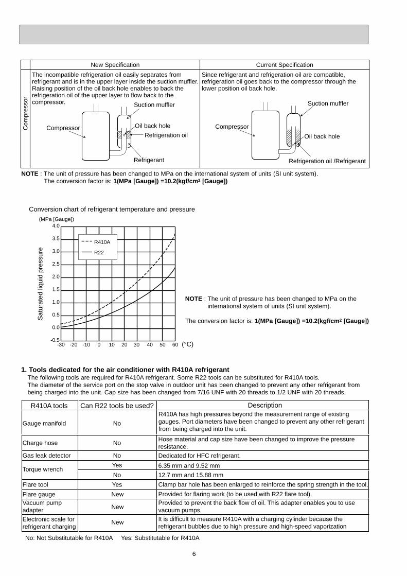
-30 -20 -10 0 10 20 30 40 50 60-0.5
0.0
0.5
1.0
1.5
2.0
2.5
3.0
3.5
4.0(MPa [Gauge])
R410A
R22
Conversion chart of refrigerant temperature and pressure
Sat
urat
ed li
quid
pre
ssur
e
(°C)
NOTE : The unit of pressure has been changed to MPa on the international system of units (SI unit system).
The conversion factor is: 1(MPa [Gauge]) =10.2(kgf/cm2 [Gauge])
R410A tools Can R22 tools be used?
Gas leak detector
R410A has high pressures beyond the measurement range of existing gauges. Port diameters have been changed to prevent any other refrigerant from being charged into the unit.
Hose material and cap size have been changed to improve the pressure resistance.Dedicated for HFC refrigerant.6.35 mm and 9.52 mm
Description
Clamp bar hole has been enlarged to reinforce the spring strength in the tool.Provided for flaring work (to be used with R22 flare tool).Provided to prevent the back flow of oil. This adapter enables you to use vacuum pumps.It is difficult to measure R410A with a charging cylinder because the refrigerant bubbles due to high pressure and high-speed vaporization
No
No
No
Yes
YesNew
New
New
Gauge manifold
Charge hose
Torque wrench
Flare toolFlare gaugeVacuum pumpadapterElectronic scale forrefrigerant charging
No: Not Substitutable for R410A Yes: Substitutable for R410A
No 12.7 mm and 15.88 mm
1. Tools dedicated for the air conditioner with R410A refrigerant The following tools are required for R410A refrigerant. Some R22 tools can be substituted for R410A tools. The diameter of the service port on the stop valve in outdoor unit has been changed to prevent any other refrigerant from being charged into the unit. Cap size has been changed from 7/16 UNF with 20 threads to 1/2 UNF with 20 threads.
NOTE : The unit of pressure has been changed to MPa on the international system of units (SI unit system).The conversion factor is: 1(MPa [Gauge]) =10.2(kgf/cm2 [Gauge])
New Specification Current SpecificationThe incompatible refrigeration oil easily separates from refrigerant and is in the upper layer inside the suction muffler.Raising position of the oil back hole enables to back the refrigeration oil of the upper layer to flow back to the compressor.
Since refrigerant and refrigeration oil are compatible, refrigeration oil goes back to the compressor through the lower position oil back hole.
Compressor
Suction muffler
Oil back holeRefrigeration oil
Refrigerant
Compressor
Suction muffler
Oil back hole
Refrigeration oil /Refrigerant
Com
pres
sor
7
Electronic scale for refrigerant charging
Outdoor unit
Refrigerant gas cylinderoperating valve
Refrigerant gas cylinderfor R410A with siphon
Refrigerant (liquid)
Service port
Gauge manifold valve (for R410A)
Union
Liquid pipe
Gas pipe
Stop valve
Indoor unit
Charge hose (for R410A)
R410A
Pipe diameter
mm6.359.5212.715.88
17222629
Dimension of flare nut
R2217222427
Flaring work and flare nut Flaring work for R410A pipe differs from that for R22 pipe. For details of flaring work, refer to Installation manual “FLARING WORK”.
3. Refrigeration oil Apply the special refrigeration oil (accessories: packed with indoor unit) to the flare and the union seat surfaces.
4. Air purge • Do not discharge the refrigerant into the atmosphere. Take care not to discharge refrigerant into the atmosphere during installation, reinstallation, or repairs to the refrigerant circuit. • Use the vacuum pump for air purging for the purpose of environmental protection.
5. Additional charge For additional charging, charge the refrigerant from liquid phase of the gas cylinder. If the refrigerant is charged from the gas phase, composition change may occur in the refrigerant inside the cylinder and the outdoor unit. In this case, ability of the refrigeration cycle decreases or normal operation can be impossible. However, charging the liquid refrigerant all at once may cause the compressor to be locked. Thus, charge the refrigerant slowly.
2. Refrigerant piping Specifications
Use the copper or copper-alloy seamless pipe for refrigerant that meet the following specifications.
Wall thicknessOutside diameter
mm6.359.5212.715.88
0.8 mm0.8 mm0.8 mm1.0 mm
Heat resisting foam plastic Specific gravity 0.045 Thickness 8 mm
Insulation material

8
PART NAMES AND FUNCTIONS2
MXZ-2A30VAMXZ-2A40VAMXZ-2A52VA
Air inlet
Air outlet
Drain outlet
Piping
Drain hose
(Back and side)
MXZ-3A54VA- E1 , E2 , E3 , E4
MXZ-4A71VA- E1 , E2 , E3 , E4
Air outlet
Drain outlet
Air inlet(Back and side)
Air outlet
Drain outlet
Air inlet(Back and side)
MXZ-3A54VA- E5 , E6 , E7
MXZ-4A71VA- E5 , E6 , E7

9
ACCESSORIES
Drain socketDrain capQuick Clean kit
1--
121
12-
MXZ-2A30VAMXZ-2A40VAMXZ-2A52VA
MXZ-3A54VA - E1
MXZ-4A71VA - E1
MXZ-3A54VA - E2 , E3 , E4 , E5 , E6 , E7
MXZ-4A71VA - E2 , E3 , E4 , E5 , E6 , E7
MXZ-4A80VAMXZ-5A100VA
MXZ-4A80VA- E1
Air outlet
Drain outlet
Air inlet(Back and side)
MXZ-4A80VA- E2
MXZ-5A100VA
Air outlet
Drain outlet
Air inlet(Back and side)

10
INDOOR/OUTDOOR CORRESPONDENCE TABLE3
MXZ-2A40VA
MXZ-2A30VA
MXZ-2A52VA
MXZ-3A54VA
There is no combination other than this table.MXZ-4A71VA MXZ-4A71VA
22+2222+2522+3525+2525+35
Indo
or u
nits
com
bina
tion
22+2222+2522+3522+4222+5025+2525+3525+4225+5035+3535+4235+5042+4242+5050+50
22+22+2222+22+2522+22+3522+22+4222+22+5022+25+2522+25+3522+25+4222+25+5022+35+3522+35+4225+25+2525+25+3525+25+4225+25+5025+35+35
Indo
or u
nits
com
bina
tion
22+2222+2522+3522+4222+5022+6025+2525+3525+4225+5025+6035+3535+4235+5035+6042+4242+5042+6050+5050+6060+60
22+22+2222+22+2522+22+3522+22+4222+22+5022+22+6022+25+2522+25+3522+25+4222+25+5022+25+6022+35+3522+35+4222+35+5022+35+6022+42+4222+42+5022+42+6022+50+5025+25+2525+25+3525+25+4225+25+5025+25+6025+35+3525+35+4225+35+5025+35+6025+42+4225+42+5025+50+5035+35+3535+35+42
Indo
or u
nits
co
mbi
natio
n
22+2222+2525+25
22+2222+2522+3525+2525+3535+35
Indo
or u
nits
co
mbi
natio
nInd
oor u
nits
comb
inatio
n
Indo
or u
nits
com
bina
tion
35+35+5035+42+42
22+22+22+2222+22+22+2522+22+22+3522+22+22+4222+22+22+5022+22+25+2522+22+25+3522+22+25+4222+22+25+5022+22+35+3522+22+35+4222+25+25+2522+25+25+3522+25+25+4222+25+25+5022+25+35+3522+25+35+4225+25+25+2525+25+25+3525+25+25+4225+25+25+5025+25+35+35

11
There is no combination other than this table.MXZ-4A80VA MXZ-4A80VA MXZ-4A80VA
Indo
or u
nits
com
bina
tion
22+2222+2522+3522+4222+5022+6022+7125+2525+3525+4225+5025+6025+7135+3535+4235+5035+6035+7142+4242+5042+6042+7150+5050+6050+7160+6060+71
22+22+2222+22+2522+22+3522+22+4222+22+5022+22+6022+22+7122+25+2522+25+3522+25+4222+25+5022+25+6022+25+7122+35+3522+35+4222+35+5022+35+6022+35+7122+42+4222+42+5022+42+6022+42+7122+50+5022+50+6022+50+7125+25+2525+25+35
Indo
or u
nits
com
bina
tion
25+25+4225+25+5025+25+6025+25+7125+35+3525+35+4225+35+5025+35+6025+35+7125+42+4225+42+5025+42+6025+42+7125+50+5025+50+6035+35+3535+35+4235+35+5035+35+6035+35+7135+42+4235+42+5035+42+6035+50+5035+50+60
22+22+22+2222+22+22+2522+22+22+3522+22+22+4222+22+22+5022+22+22+6022+22+22+7122+22+25+2522+22+25+3522+22+25+4222+22+25+5022+22+25+6022+22+25+7122+22+35+3522+22+35+4222+22+35+5022+22+35+6022+22+42+4222+22+42+5022+22+50+5022+25+25+2522+25+25+3522+25+25+4222+25+25+5022+25+25+6022+25+35+3522+25+35+4222+25+35+5022+25+35+60
Indo
or u
nits
com
bina
tion
22+35+35+3522+35+35+4222+35+35+5022+35+42+4225+25+25+2525+25+25+3525+25+25+4225+25+25+5025+25+25+6025+25+35+3525+25+35+4225+25+35+5025+35+35+3525+35+35+4235+35+35+35

12
22+60+6022+60+7125+25+2525+25+3525+25+4225+25+5025+25+6025+25+7125+35+3525+35+4225+35+5025+35+6025+35+7125+42+4225+42+5025+42+6025+42+7125+50+5025+50+6025+50+7125+60+6025+60+7135+35+3535+35+4235+35+5035+35+6035+35+7135+42+4235+42+5035+42+6035+42+7135+50+5035+50+6035+50+7135+60+6035+60+7142+42+4242+42+5042+42+6042+42+7142+50+5042+50+6042+50+7142+60+6050+50+5050+50+6050+50+71
22+22+22+2222+22+22+2522+22+22+3522+22+22+4222+22+22+5022+22+22+60
22+22+22+7122+22+25+2522+22+25+3522+22+25+4222+22+25+5022+22+25+6022+22+25+7122+22+35+3522+22+35+4222+22+35+5022+22+35+6022+22+35+7122+22+42+4222+22+42+5022+22+42+6022+22+42+7122+22+50+5022+22+50+6022+22+50+7122+25+25+2522+25+25+3522+25+25+4222+25+25+5022+25+25+6022+25+25+7122+25+35+3522+25+35+4222+25+35+5022+25+35+6022+25+35+7122+25+42+4222+25+42+5022+25+42+6022+25+42+7122+25+50+5022+25+50+6022+25+50+7122+35+35+3522+35+35+4222+35+35+5022+35+35+6022+35+35+7122+35+42+4222+35+42+5022+35+42+6022+35+42+7122+35+50+5022+35+50+6022+42+42+4222+42+42+5022+42+42+6022+42+50+5025+25+25+25
25+25+25+3525+25+25+4225+25+25+5025+25+25+6025+25+25+7125+25+35+3525+25+35+4225+25+35+5025+25+35+6025+25+35+7125+25+42+4225+25+42+5025+25+42+6025+25+42+7125+25+50+5025+25+50+6025+25+50+7125+35+35+3525+35+35+4225+35+35+5025+35+35+6025+35+35+7125+35+42+4225+35+42+5025+35+42+6025+42+42+4225+42+42+5025+42+42+6025+42+50+5035+35+35+3535+35+35+4235+35+35+5035+35+35+6035+35+42+4235+35+42+5035+42+42+4235+42+42+5042+42+42+42
22+22+22+22+2222+22+22+22+2522+22+22+22+3522+22+22+22+4222+22+22+22+5022+22+22+22+6022+22+22+22+7122+22+22+25+2522+22+22+25+3522+22+22+25+4222+22+22+25+5022+22+22+25+6022+22+22+25+7122+22+22+35+3522+22+22+35+42
22+2222+2522+3522+4222+5022+6022+7125+2525+3525+4225+5025+6025+7135+3535+4235+5035+6035+7142+4242+5042+6042+7150+5050+6050+7160+6060+7171+71
22+22+2222+22+2522+22+3522+22+4222+22+5022+22+6022+22+7122+25+2522+25+3522+25+4222+25+5022+25+6022+25+7122+35+3522+35+4222+35+5022+35+6022+35+7122+42+4222+42+5022+42+6022+42+7122+50+5022+50+6022+50+71
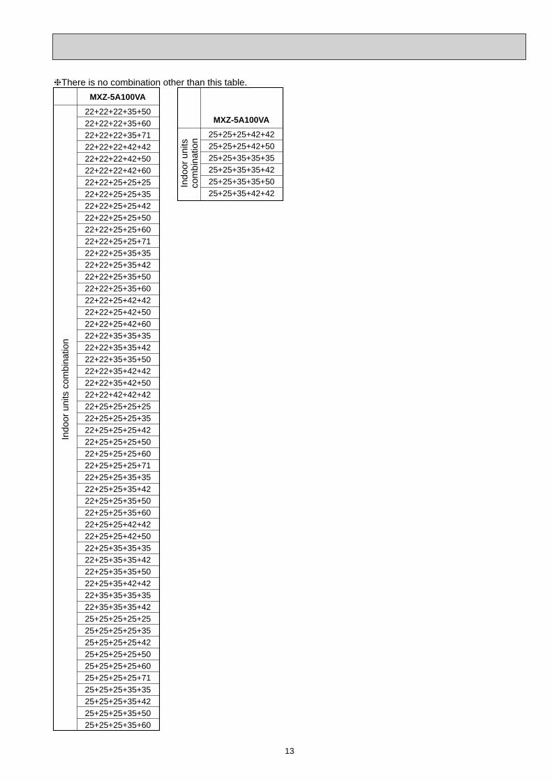
There is no combination other than this table.
Indo
or u
nits
com
bina
tion
MXZ-5A100VA
Indo
or u
nits
com
bina
tion
MXZ-5A100VA
Indo
or u
nits
com
bina
tion
MXZ-5A100VA
Indo
or u
nits
com
bina
tion
MXZ-5A100VA
13
22+22+22+35+5022+22+22+35+6022+22+22+35+7122+22+22+42+4222+22+22+42+5022+22+22+42+6022+22+25+25+2522+22+25+25+3522+22+25+25+4222+22+25+25+5022+22+25+25+6022+22+25+25+7122+22+25+35+3522+22+25+35+4222+22+25+35+5022+22+25+35+6022+22+25+42+4222+22+25+42+5022+22+25+42+6022+22+35+35+3522+22+35+35+4222+22+35+35+5022+22+35+42+4222+22+35+42+5022+22+42+42+4222+25+25+25+2522+25+25+25+3522+25+25+25+4222+25+25+25+5022+25+25+25+6022+25+25+25+7122+25+25+35+3522+25+25+35+4222+25+25+35+5022+25+25+35+6022+25+25+42+4222+25+25+42+5022+25+35+35+3522+25+35+35+4222+25+35+35+5022+25+35+42+4222+35+35+35+3522+35+35+35+4225+25+25+25+2525+25+25+25+3525+25+25+25+4225+25+25+25+5025+25+25+25+6025+25+25+25+7125+25+25+35+3525+25+25+35+4225+25+25+35+5025+25+25+35+60
25+25+25+42+4225+25+25+42+5025+25+35+35+3525+25+35+35+4225+25+35+35+5025+25+35+42+42
There is no combination other than this table.
Indo
or u
nits
com
bina
tion
MXZ-5A100VA
Indo
or u
nits
com
bina
tion
MXZ-5A100VA

14
22
25
22+22
22+25
25+25
Indoor unitscombination Unit A Unit B
Cooling capacity (kW)Total
Outdoor unitpower consumption
(kW)Current
(A)Powerfactor(%)
NOTE: Electrical data is for outdoor unit only.MXZ-2A30VA
90
90
90
90
90
2.08
2.37
2.61
2.73
2.87
2.2(0.9 - 3.0)
2.5(0.9 - 3.3)
2.8( 1.1 - 3.8)
2.9(1.1 - 3.9)
3.0(1.1 - 4.0)
0.430(0.120 - 0.620)
0.490(0.120 - 0.690)
0.540(0.250 - 0.970)
0.565(0.250 - 1.020)
0.595(0.250 - 1.070)
–
–
1.40
1.50
1.50
2.20
2.50
1.40
1.40
1.50
INDOOR UNITS COMBINATION4
22
25
22+22
22+25
25+25
Indoor unitscombination Unit A Unit B
Heating capacity (kW)Total
Outdoor unitpower consumption
(kW)Current
(A)Powerfactor(%)
NOTE: Electrical data is for outdoor unit only.
90
90
90
90
90
3.24
3.53
3.41
3.50
3.60
3.3(0.9 - 4.0)
3.6(0.9 - 4.5)
3.8(1.0 - 4.3)
3.9(1.0 - 4.4)
4.0(1.0 - 4.5)
0.670(0.110 - 0.910)
0.730(0.110 - 1.050)
0.705(0.200 - 0.770)
0.725( 0.200 - 0.795)
0.745(0.200 - 0.810)
–
–
1.90
2.00
2.00
3.30
3.60
1.90
1.90
2.00

15
22
25
35
22+22
22+25
22+35
25+25
25+35
Indoor unitscombination Unit A Unit B
Cooling capacity (kW)Total
Outdoor unitpower consumption
(kW)Current
(A)Powerfactor(%)
NOTE: Electrical data is for outdoor unit only.MXZ-2A40VA
90
90
90
95
95
95
95
95
2.08
2.37
3.53
3.80
4.44
4.44
4.44
4.78
2.2(0.9 - 3.0)
2.5(0.9 - 3.3)
3.5(0.9 - 4.0)
3.8( 1.1 - 4.3)
3.9(1.1 - 4.3)
3.9(1.1 - 4.4)
3.9(1.1 - 4.4)
4.0(1.1 - 4.5)
0.430(0.120 - 0.620)
0.490(0.120 - 0.690)
0.730(0.120 - 0.900)
0.830(0.250 - 1.110)
0.970(0.250 - 1.110)
0.970(0.250 - 1.130)
0.970(0.250 - 1.130)
1.045(0.250 - 1.170)
–
–
–
1.90
2.07
2.39
1.95
2.33
2.20
2.50
3.50
1.90
1.83
1.51
1.95
1.67
22
25
35
22+22
22+25
22+35
25+25
25+35
Indoor unitscombination Unit A Unit B
Heating capacity (kW)Total
Outdoor unitpower consumption
(kW)Current
(A)Powerfactor(%)
NOTE: Electrical data is for outdoor unit only.
90
90
90
95
95
95
95
95
3.24
3.53
4.20
4.16
4.16
4.16
4.16
4.32
3.3(0.9 - 4.0)
3.6(0.9 - 4.5)
4.0(0.9 - 4.8)
4.4(1.0 - 4.8)
4.4(1.0 - 4.8)
4.4(1.0 - 4.9)
4.4(1.0 - 4.9)
4.5(1.0 - 5.0)
0.670(0.110 - 0.910)
0.730(0.110 - 1.050)
0.870(0.110 - 1.150)
0.910(0.200 - 1.010)
0.910( 0.200 - 1.010)
0.910(0.200 - 1.030)
0.910(0.200 - 1.030)
0.945(0.200 - 1.050)
–
–
–
2.20
2.34
2.70
2.20
2.65
3.30
3.60
4.00
2.20
2.06
1.70
2.20
1.85
16
22
25
35
22+22
22+25
22+35
25+25
25+35
35+35
Indoor unitscombination Unit A Unit B
Cooling capacity (kW)Total
Outdoor unitpower consumption
(kW)Current
(A)Powerfactor(%)
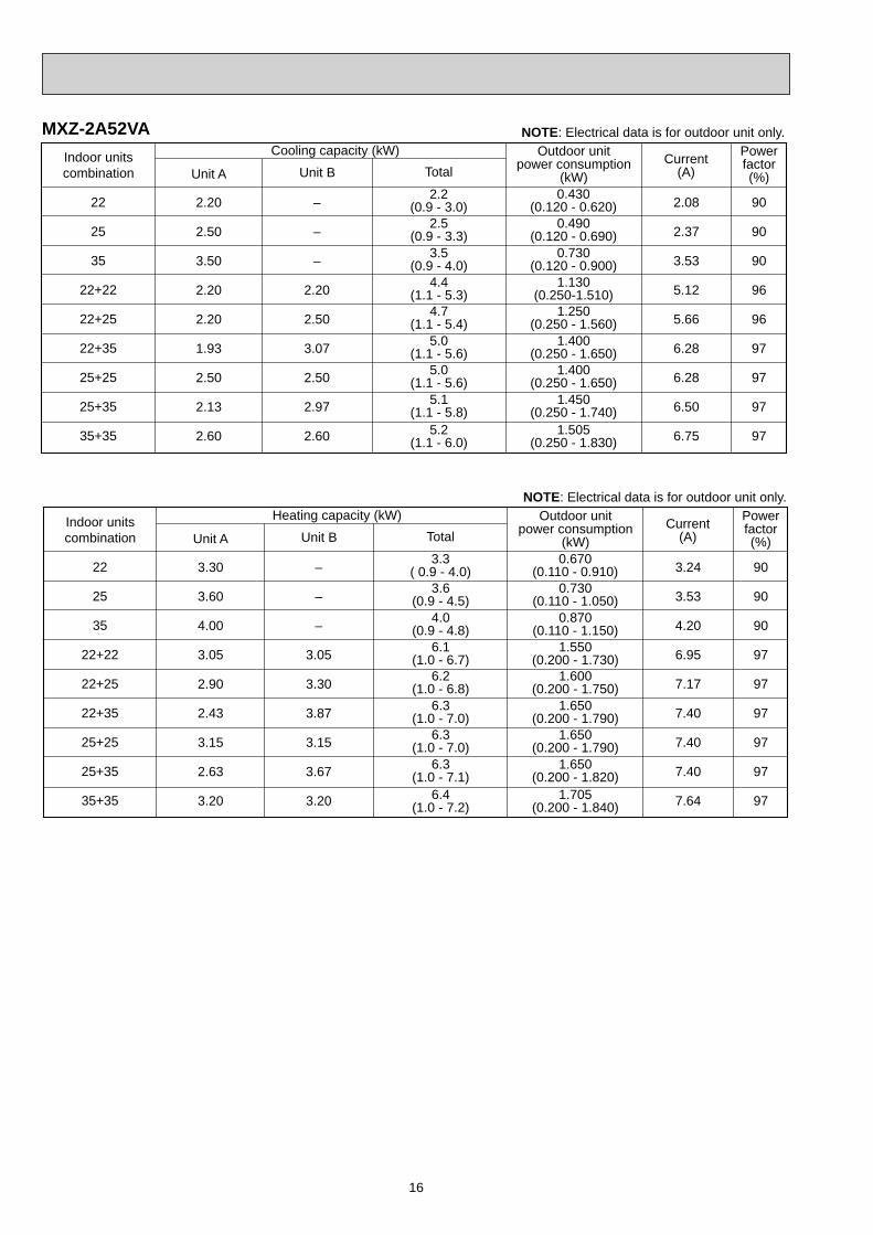
NOTE: Electrical data is for outdoor unit only.MXZ-2A52VA
90
90
90
96
96
97
97
97
97
2.08
2.37
3.53
5.12
5.66
6.28
6.28
6.50
6.75
2.2(0.9 - 3.0)
2.5(0.9 - 3.3)
3.5(0.9 - 4.0)
4.4(1.1 - 5.3)
4.7(1.1 - 5.4)
5.0(1.1 - 5.6)
5.0(1.1 - 5.6)
5.1(1.1 - 5.8)
0.430(0.120 - 0.620)
0.490(0.120 - 0.690)
0.730(0.120 - 0.900)
1.130(0.250-1.510)
1.250(0.250 - 1.560)
1.400(0.250 - 1.650)
1.400(0.250 - 1.650)
1.450(0.250 - 1.740)
5.2(1.1 - 6.0)
1.505(0.250 - 1.830)
–
–
–
2.20
2.50
3.07
2.50
2.97
2.60
2.20
2.50
3.50
2.20
2.20
1.93
2.50
2.13
2.60
22
25
35
22+22
22+25
22+35
25+25
25+35
35+35
Indoor unitscombination Unit A Unit B
Heating capacity (kW)Total
Outdoor unitpower consumption
(kW)Current
(A)Powerfactor(%)
NOTE: Electrical data is for outdoor unit only.
90
90
90
97
97
97
97
97
97
3.24
3.53
4.20
6.95
7.17
7.40
7.40
7.40
7.64
3.3( 0.9 - 4.0)
3.6(0.9 - 4.5)
4.0(0.9 - 4.8)
6.1(1.0 - 6.7)
6.2(1.0 - 6.8)
6.3(1.0 - 7.0)
6.3(1.0 - 7.0)
6.3(1.0 - 7.1)
0.670(0.110 - 0.910)
0.730(0.110 - 1.050)
0.870(0.110 - 1.150)
1.550(0.200 - 1.730)
1.600(0.200 - 1.750)
1.650(0.200 - 1.790)
1.650(0.200 - 1.790)
1.650(0.200 - 1.820)
6.4(1.0 - 7.2)
1.705(0.200 - 1.840)
–
–
–
3.05
3.30
3.87
3.15
3.67
3.20
3.30
3.60
4.00
3.05
2.90
2.43
3.15
2.63
3.20
17
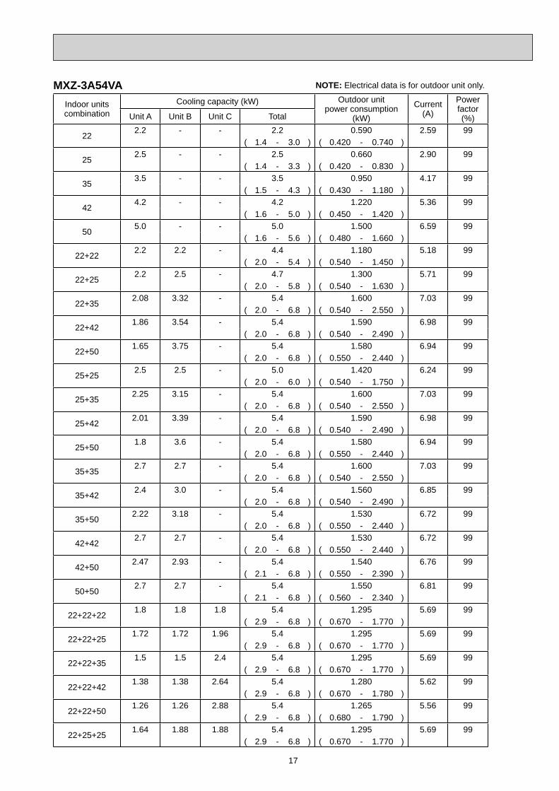
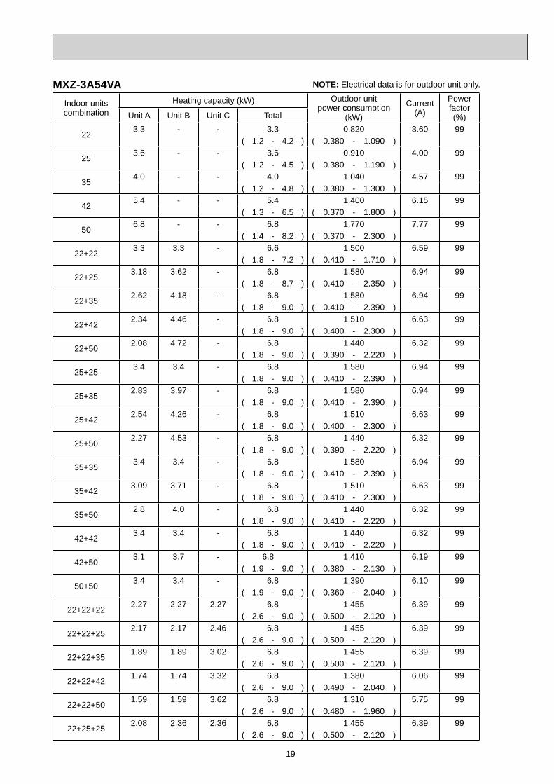
MXZ-3A54VA NOTE: Electrical data is for outdoor unit only.
Indoor unitscombination
Cooling capacity (kW) Outdoor unitpower consumption
(kW)
Current(A)
Powerfactor(%)Unit A Unit B Unit C Total
222.2 - - 2.2 0.590 2.59 99
( 1.4 - 3.0 ) ( 0.420 - 0.740 )
252.5 - - 2.5 0.660 2.90 99
( 1.4 - 3.3 ) ( 0.420 - 0.830 )
353.5 - - 3.5 0.950 4.17 99
( 1.5 - 4.3 ) ( 0.430 - 1.180 )
424.2 - - 4.2 1.220 5.36 99
( 1.6 - 5.0 ) ( 0.450 - 1.420 )
505.0 - - 5.0 1.500 6.59 99
( 1.6 - 5.6 ) ( 0.480 - 1.660 )
22+222.2 2.2 - 4.4 1.180 5.18 99
( 2.0 - 5.4 ) ( 0.540 - 1.450 )
22+252.2 2.5 - 4.7 1.300 5.71 99
( 2.0 - 5.8 ) ( 0.540 - 1.630 )
22+352.08 3.32 - 5.4 1.600 7.03 99
( 2.0 - 6.8 ) ( 0.540 - 2.550 )
22+421.86 3.54 - 5.4 1.590 6.98 99
( 2.0 - 6.8 ) ( 0.540 - 2.490 )
22+501.65 3.75 - 5.4 1.580 6.94 99
( 2.0 - 6.8 ) ( 0.550 - 2.440 )
25+252.5 2.5 - 5.0 1.420 6.24 99
( 2.0 - 6.0 ) ( 0.540 - 1.750 )
25+352.25 3.15 - 5.4 1.600 7.03 99
( 2.0 - 6.8 ) ( 0.540 - 2.550 )
25+422.01 3.39 - 5.4 1.590 6.98 99
( 2.0 - 6.8 ) ( 0.540 - 2.490 )
25+501.8 3.6 - 5.4 1.580 6.94 99
( 2.0 - 6.8 ) ( 0.550 - 2.440 )
35+352.7 2.7 - 5.4 1.600 7.03 99
( 2.0 - 6.8 ) ( 0.540 - 2.550 )
35+422.4 3.0 - 5.4 1.560 6.85 99
( 2.0 - 6.8 ) ( 0.540 - 2.490 )
35+502.22 3.18 - 5.4 1.530 6.72 99
( 2.0 - 6.8 ) ( 0.550 - 2.440 )
42+422.7 2.7 - 5.4 1.530 6.72 99
( 2.0 - 6.8 ) ( 0.550 - 2.440 )
42+502.47 2.93 - 5.4 1.540 6.76 99
( 2.1 - 6.8 ) ( 0.550 - 2.390 )
50+502.7 2.7 - 5.4 1.550 6.81 99
( 2.1 - 6.8 ) ( 0.560 - 2.340 )
22+22+221.8 1.8 1.8 5.4 1.295 5.69 99
( 2.9 - 6.8 ) ( 0.670 - 1.770 )
22+22+251.72 1.72 1.96 5.4 1.295 5.69 99
( 2.9 - 6.8 ) ( 0.670 - 1.770 )
22+22+351.5 1.5 2.4 5.4 1.295 5.69 99
( 2.9 - 6.8 ) ( 0.670 - 1.770 )
22+22+421.38 1.38 2.64 5.4 1.280 5.62 99
( 2.9 - 6.8 ) ( 0.670 - 1.780 )
22+22+501.26 1.26 2.88 5.4 1.265 5.56 99
( 2.9 - 6.8 ) ( 0.680 - 1.790 )
22+25+251.64 1.88 1.88 5.4 1.295 5.69 99
( 2.9 - 6.8 ) ( 0.670 - 1.770 )
18
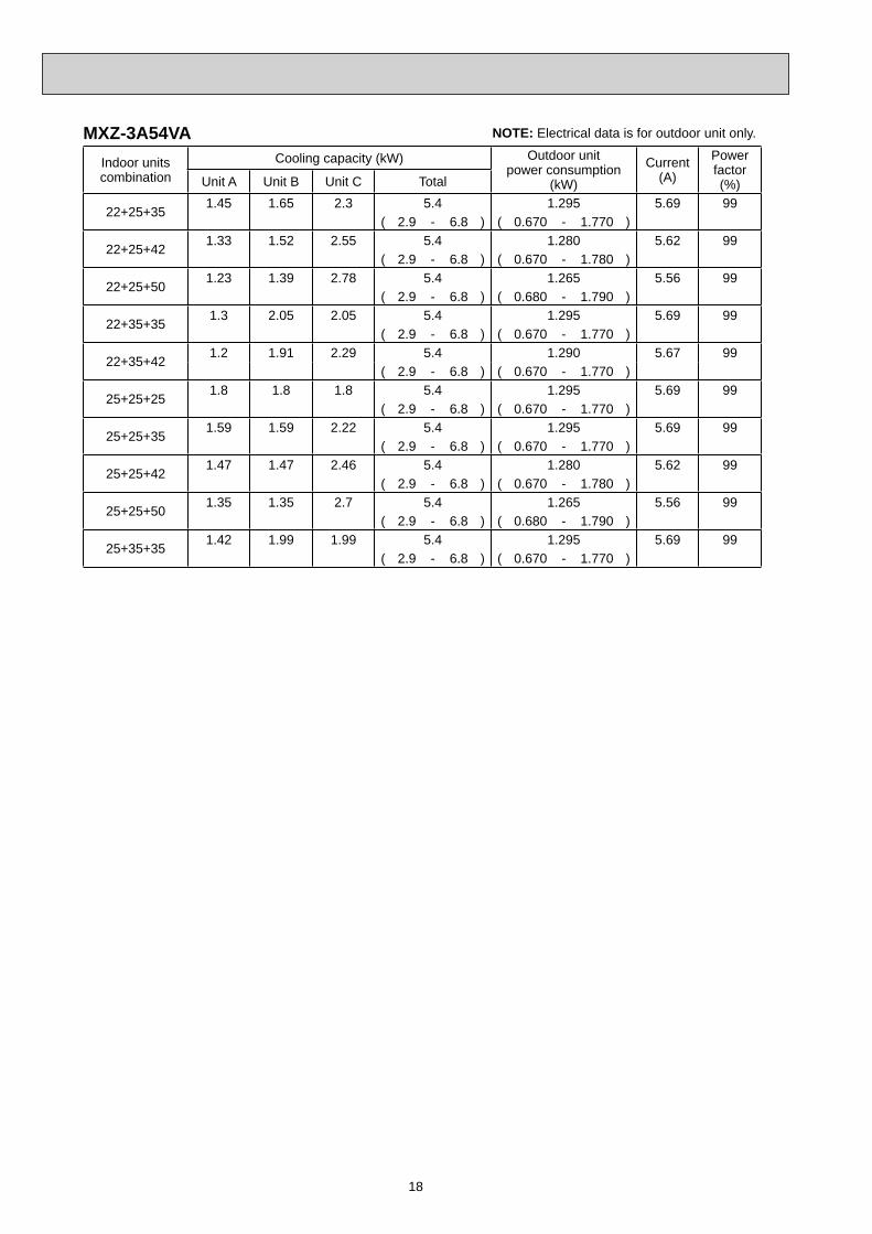
MXZ-3A54VA NOTE: Electrical data is for outdoor unit only.
Indoor unitscombination
Cooling capacity (kW) Outdoor unitpower consumption
(kW)
Current(A)
Powerfactor(%)Unit A Unit B Unit C Total
22+25+351.45 1.65 2.3 5.4 1.295 5.69 99
( 2.9 - 6.8 ) ( 0.670 - 1.770 )
22+25+421.33 1.52 2.55 5.4 1.280 5.62 99
( 2.9 - 6.8 ) ( 0.670 - 1.780 )
22+25+501.23 1.39 2.78 5.4 1.265 5.56 99
( 2.9 - 6.8 ) ( 0.680 - 1.790 )
22+35+351.3 2.05 2.05 5.4 1.295 5.69 99
( 2.9 - 6.8 ) ( 0.670 - 1.770 )
22+35+421.2 1.91 2.29 5.4 1.290 5.67 99
( 2.9 - 6.8 ) ( 0.670 - 1.770 )
25+25+251.8 1.8 1.8 5.4 1.295 5.69 99
( 2.9 - 6.8 ) ( 0.670 - 1.770 )
25+25+351.59 1.59 2.22 5.4 1.295 5.69 99
( 2.9 - 6.8 ) ( 0.670 - 1.770 )
25+25+421.47 1.47 2.46 5.4 1.280 5.62 99
( 2.9 - 6.8 ) ( 0.670 - 1.780 )
25+25+501.35 1.35 2.7 5.4 1.265 5.56 99
( 2.9 - 6.8 ) ( 0.680 - 1.790 )
25+35+351.42 1.99 1.99 5.4 1.295 5.69 99
( 2.9 - 6.8 ) ( 0.670 - 1.770 )
19
MXZ-3A54VA NOTE: Electrical data is for outdoor unit only.
Indoor unitscombination
Heating capacity (kW) Outdoor unitpower consumption
(kW)
Current(A)
Powerfactor(%)Unit A Unit B Unit C Total
223.3 - - 3.3 0.820 3.60 99
( 1.2 - 4.2 ) ( 0.380 - 1.090 )
253.6 - - 3.6 0.910 4.00 99
( 1.2 - 4.5 ) ( 0.380 - 1.190 )
354.0 - - 4.0 1.040 4.57 99
( 1.2 - 4.8 ) ( 0.380 - 1.300 )
425.4 - - 5.4 1.400 6.15 99
( 1.3 - 6.5 ) ( 0.370 - 1.800 )
506.8 - - 6.8 1.770 7.77 99
( 1.4 - 8.2 ) ( 0.370 - 2.300 )
22+223.3 3.3 - 6.6 1.500 6.59 99
( 1.8 - 7.2 ) ( 0.410 - 1.710 )
22+253.18 3.62 - 6.8 1.580 6.94 99
( 1.8 - 8.7 ) ( 0.410 - 2.350 )
22+352.62 4.18 - 6.8 1.580 6.94 99
( 1.8 - 9.0 ) ( 0.410 - 2.390 )
22+422.34 4.46 - 6.8 1.510 6.63 99
( 1.8 - 9.0 ) ( 0.400 - 2.300 )
22+502.08 4.72 - 6.8 1.440 6.32 99
( 1.8 - 9.0 ) ( 0.390 - 2.220 )
25+253.4 3.4 - 6.8 1.580 6.94 99
( 1.8 - 9.0 ) ( 0.410 - 2.390 )
25+352.83 3.97 - 6.8 1.580 6.94 99
( 1.8 - 9.0 ) ( 0.410 - 2.390 )
25+422.54 4.26 - 6.8 1.510 6.63 99
( 1.8 - 9.0 ) ( 0.400 - 2.300 )
25+502.27 4.53 - 6.8 1.440 6.32 99
( 1.8 - 9.0 ) ( 0.390 - 2.220 )
35+353.4 3.4 - 6.8 1.580 6.94 99
( 1.8 - 9.0 ) ( 0.410 - 2.390 )
35+423.09 3.71 - 6.8 1.510 6.63 99
( 1.8 - 9.0 ) ( 0.410 - 2.300 )
35+502.8 4.0 - 6.8 1.440 6.32 99
( 1.8 - 9.0 ) ( 0.410 - 2.220 )
42+423.4 3.4 - 6.8 1.440 6.32 99
( 1.8 - 9.0 ) ( 0.410 - 2.220 )
42+503.1 3.7 - 6.8 1.410 6.19 99
( 1.9 - 9.0 ) ( 0.380 - 2.130 )
50+503.4 3.4 - 6.8 1.390 6.10 99
( 1.9 - 9.0 ) ( 0.360 - 2.040 )
22+22+222.27 2.27 2.27 6.8 1.455 6.39 99
( 2.6 - 9.0 ) ( 0.500 - 2.120 )
22+22+252.17 2.17 2.46 6.8 1.455 6.39 99
( 2.6 - 9.0 ) ( 0.500 - 2.120 )
22+22+351.89 1.89 3.02 6.8 1.455 6.39 99
( 2.6 - 9.0 ) ( 0.500 - 2.120 )
22+22+421.74 1.74 3.32 6.8 1.380 6.06 99
( 2.6 - 9.0 ) ( 0.490 - 2.040 )
22+22+501.59 1.59 3.62 6.8 1.310 5.75 99
( 2.6 - 9.0 ) ( 0.480 - 1.960 )
22+25+252.08 2.36 2.36 6.8 1.455 6.39 99
( 2.6 - 9.0 ) ( 0.500 - 2.120 )
20
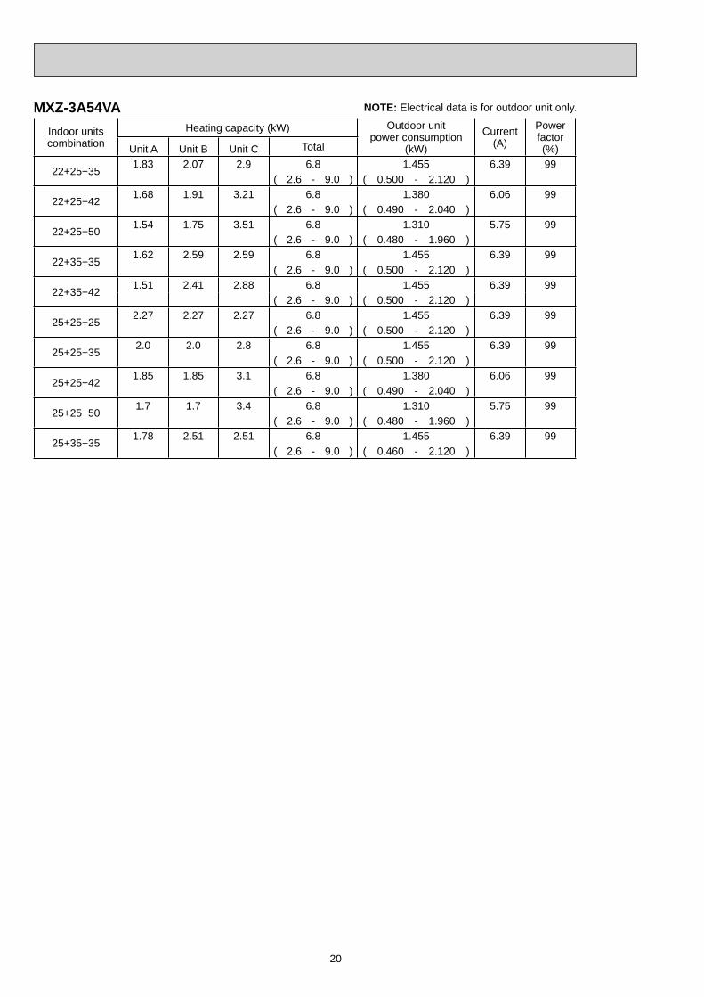
MXZ-3A54VA NOTE: Electrical data is for outdoor unit only.
Indoor unitscombination
Heating capacity (kW) Outdoor unitpower consumption
(kW)
Current(A)
Powerfactor(%)Unit A Unit B Unit C Total
22+25+351.83 2.07 2.9 6.8 1.455 6.39 99
( 2.6 - 9.0 ) ( 0.500 - 2.120 )
22+25+421.68 1.91 3.21 6.8 1.380 6.06 99
( 2.6 - 9.0 ) ( 0.490 - 2.040 )
22+25+501.54 1.75 3.51 6.8 1.310 5.75 99
( 2.6 - 9.0 ) ( 0.480 - 1.960 )
22+35+351.62 2.59 2.59 6.8 1.455 6.39 99
( 2.6 - 9.0 ) ( 0.500 - 2.120 )
22+35+421.51 2.41 2.88 6.8 1.455 6.39 99
( 2.6 - 9.0 ) ( 0.500 - 2.120 )
25+25+252.27 2.27 2.27 6.8 1.455 6.39 99
( 2.6 - 9.0 ) ( 0.500 - 2.120 )
25+25+352.0 2.0 2.8 6.8 1.455 6.39 99
( 2.6 - 9.0 ) ( 0.500 - 2.120 )
25+25+421.85 1.85 3.1 6.8 1.380 6.06 99
( 2.6 - 9.0 ) ( 0.490 - 2.040 )
25+25+501.7 1.7 3.4 6.8 1.310 5.75 99
( 2.6 - 9.0 ) ( 0.480 - 1.960 )
25+35+351.78 2.51 2.51 6.8 1.455 6.39 99
( 2.6 - 9.0 ) ( 0.460 - 2.120 )

21
MXZ-4A71VA NOTE: Electrical data is for outdoor unit only.
Indoor unitscombination
Cooling capacity (kW) Outdoor unitpower consumption
(kW)
Current(A)
Powerfactor(%)Unit A Unit B Unit C Unit D Total
222.2 - - - 2.2 0.590 2.59 99
( 1.4 - 3.0 ) ( 0.420 - 0.740 )
252.5 - - - 2.5 0.660 2.90 99
( 1.4 - 3.3 ) ( 0.420 - 0.830 )
353.5 - - - 3.5 0.950 4.17 99
( 1.5 - 4.3 ) ( 0.430 - 1.180 )
424.2 - - - 4.2 1.220 5.36 99
( 1.6 - 5.0 ) ( 0.450 - 1.420 )
505.0 - - - 5.0 1.500 6.59 99
( 1.6 - 5.6 ) ( 0.480 - 1.660 )
606.0 - - - 6.0 2.110 9.27 99
( 1.6 - 6.6 ) ( 0.480 - 2.290 )
22+222.2 2.2 - - 4.4 1.180 5.18 99
( 2.0 - 5.4 ) ( 0.540 - 1.450 )
22+252.2 2.5 - - 4.7 1.300 5.71 99
( 2.0 - 5.8 ) ( 0.540 - 1.630 )
22+352.2 3.5 - - 5.7 1.800 7.91 99
( 2.0 - 6.6 ) ( 0.540 - 2.100 )
22+422.2 4.2 - - 6.4 2.120 9.31 99
( 2.0 - 7.1 ) ( 0.540 - 2.540 )
22+502.08 4.72 - - 6.8 2.440 10.72 99
( 2.0 - 7.1 ) ( 0.550 - 2.570 )
22+601.82 4.98 - - 6.8 2.460 10.80 99
( 2.0 - 7.1 ) ( 0.550 - 2.600 )
25+252.5 2.5 - - 5.0 1.420 6.24 99
( 2.0 - 6.0 ) ( 0.540 - 1.750 )
25+352.5 3.5 - - 6.0 2.010 8.83 99
( 2.0 - 7.1 ) ( 0.540 - 2.540 )
25+422.5 4.2 - - 6.7 2.220 9.75 99
( 2.0 - 7.1 ) ( 0.540 - 2.560 )
25+502.27 4.53 - - 6.8 2.440 10.72 99
( 2.0 - 7.1 ) ( 0.550 - 2.590 )
25+602.0 4.8 - - 6.8 2.460 10.80 99
( 2.0 - 7.1 ) ( 0.550 - 2.600 )
35+353.4 3.4 - - 6.8 2.570 11.29 99
( 2.0 - 7.1 ) ( 0.540 - 2.600 )
35+423.09 3.71 - - 6.8 2.500 10.98 99
( 2.0 - 7.1 ) ( 0.540 - 2.600 )
35+502.8 4.0 - - 6.8 2.440 10.72 99
( 2.0 - 7.1 ) ( 0.550 - 2.600 )
35+602.51 4.29 - - 6.8 2.460 10.80 99
( 2.0 - 7.1 ) ( 0.550 - 2.610 )
42+423.4 3.4 - - 6.8 2.500 10.98 99
( 2.0 - 7.1 ) ( 0.540 - 2.600 )
42+503.1 3.7 - - 6.8 2.440 10.72 99
( 2.0 - 7.1 ) ( 0.550 - 2.600 )
42+602.8 4.0 - - 6.8 2.460 10.80 99
( 2.0 - 7.1 ) ( 0.550 - 2.610 )
50+503.4 3.4 - - 6.8 2.380 10.45 99
( 2.1 - 7.1 ) ( 0.560 - 2.610 )
50+603.09 3.71 - - 6.8 2.400 10.54 99
( 2.1 - 7.1 ) ( 0.570 - 2.620 )
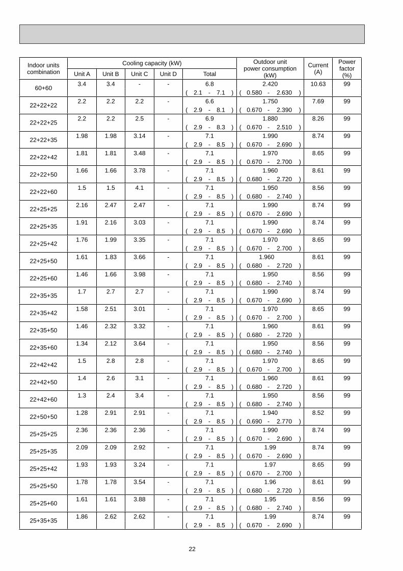
22
Indoor unitscombination
Cooling capacity (kW) Outdoor unitpower consumption
(kW)
Current(A)
Powerfactor(%)Unit A Unit B Unit C Unit D Total
60+603.4 3.4 - - 6.8 2.420 10.63 99
( 2.1 - 7.1 ) ( 0.580 - 2.630 )
22+22+222.2 2.2 2.2 - 6.6 1.750 7.69 99
( 2.9 - 8.1 ) ( 0.670 - 2.390 )
22+22+252.2 2.2 2.5 - 6.9 1.880 8.26 99
( 2.9 - 8.3 ) ( 0.670 - 2.510 )
22+22+351.98 1.98 3.14 - 7.1 1.990 8.74 99
( 2.9 - 8.5 ) ( 0.670 - 2.690 )
22+22+421.81 1.81 3.48 - 7.1 1.970 8.65 99
( 2.9 - 8.5 ) ( 0.670 - 2.700 )
22+22+501.66 1.66 3.78 - 7.1 1.960 8.61 99
( 2.9 - 8.5 ) ( 0.680 - 2.720 )
22+22+601.5 1.5 4.1 - 7.1 1.950 8.56 99
( 2.9 - 8.5 ) ( 0.680 - 2.740 )
22+25+252.16 2.47 2.47 - 7.1 1.990 8.74 99
( 2.9 - 8.5 ) ( 0.670 - 2.690 )
22+25+351.91 2.16 3.03 - 7.1 1.990 8.74 99
( 2.9 - 8.5 ) ( 0.670 - 2.690 )
22+25+421.76 1.99 3.35 - 7.1 1.970 8.65 99
( 2.9 - 8.5 ) ( 0.670 - 2.700 )
22+25+501.61 1.83 3.66 - 7.1 1.960 8.61 99
( 2.9 - 8.5 ) ( 0.680 - 2.720 )
22+25+601.46 1.66 3.98 - 7.1 1.950 8.56 99
( 2.9 - 8.5 ) ( 0.680 - 2.740 )
22+35+351.7 2.7 2.7 - 7.1 1.990 8.74 99
( 2.9 - 8.5 ) ( 0.670 - 2.690 )
22+35+421.58 2.51 3.01 - 7.1 1.970 8.65 99
( 2.9 - 8.5 ) ( 0.670 - 2.700 )
22+35+501.46 2.32 3.32 - 7.1 1.960 8.61 99
( 2.9 - 8.5 ) ( 0.680 - 2.720 )
22+35+601.34 2.12 3.64 - 7.1 1.950 8.56 99
( 2.9 - 8.5 ) ( 0.680 - 2.740 )
22+42+421.5 2.8 2.8 - 7.1 1.970 8.65 99
( 2.9 - 8.5 ) ( 0.670 - 2.700 )
22+42+501.4 2.6 3.1 - 7.1 1.960 8.61 99
( 2.9 - 8.5 ) ( 0.680 - 2.720 )
22+42+601.3 2.4 3.4 - 7.1 1.950 8.56 99
( 2.9 - 8.5 ) ( 0.680 - 2.740 )
22+50+501.28 2.91 2.91 - 7.1 1.940 8.52 99
( 2.9 - 8.5 ) ( 0.690 - 2.770 )
25+25+252.36 2.36 2.36 - 7.1 1.990 8.74 99
( 2.9 - 8.5 ) ( 0.670 - 2.690 )
25+25+352.09 2.09 2.92 - 7.1 1.99 8.74 99
( 2.9 - 8.5 ) ( 0.670 - 2.690 )
25+25+421.93 1.93 3.24 - 7.1 1.97 8.65 99
( 2.9 - 8.5 ) ( 0.670 - 2.700 )
25+25+501.78 1.78 3.54 - 7.1 1.96 8.61 99
( 2.9 - 8.5 ) ( 0.680 - 2.720 )
25+25+601.61 1.61 3.88 - 7.1 1.95 8.56 99
( 2.9 - 8.5 ) ( 0.680 - 2.740 )
25+35+351.86 2.62 2.62 - 7.1 1.99 8.74 99
( 2.9 - 8.5 ) ( 0.670 - 2.690 )
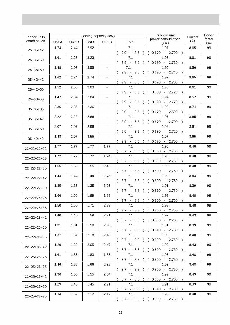
23
Indoor unitscombination
Cooling capacity (kW) Outdoor unitpower consumption
(kW)
Current(A)
Powerfactor(%)Unit A Unit B Unit C Unit D Total
25+35+421.74 2.44 2.92 - 7.1 1.97 8.65 99
( 2.9 - 8.5 ) ( 0.670 - 2.700 )
25+35+501.61 2.26 3.23 - 7.1 1.96 8.61 99
( 2.9 - 8.5 ) ( 0.680 - 2.720 )
25+35+601.48 2.07 3.55 - 7.1 1.95 8.56 99
( 2.9 - 8.5 ) ( 0.680 - 2.740 )
25+42+421.62 2.74 2.74 - 7.1 1.97 8.65 99
( 2.9 - 8.5 ) ( 0.670 - 2.700 )
25+42+501.52 2.55 3.03 - 7.1 1.96 8.61 99
( 2.9 - 8.5 ) ( 0.680 - 2.720 )
25+50+501.42 2.84 2.84 - 7.1 1.94 8.52 99
( 2.9 - 8.5 ) ( 0.690 - 2.770 )
35+35+352.36 2.36 2.36 - 7.1 1.99 8.74 99
( 2.9 - 8.5 ) ( 0.670 - 2.690 )
35+35+422.22 2.22 2.66 - 7.1 1.97 8.65 99
( 2.9 - 8.5 ) ( 0.670 - 2.700 )
35+35+502.07 2.07 2.96 - 7.1 1.96 8.61 99
( 2.9 - 8.5 ) ( 0.680 - 2.720 )
35+42+421.48 2.07 3.55 - 7.1 1.97 8.65 99
( 2.9 - 8.5 ) ( 0.670 - 2.700 )
22+22+22+221.77 1.77 1.77 1.77 7.1 1.93 8.48 99
( 3.7 - 8.8 ) ( 0.800 - 2.750 )
22+22+22+251.72 1.72 1.72 1.94 7.1 1.93 8.48 99
( 3.7 - 8.8 ) ( 0.800 - 2.750 )
22+22+22+351.55 1.55 1.55 2.45 7.1 1.93 8.48 99
( 3.7 - 8.8 ) ( 0.800 - 2.750 )
22+22+22+421.44 1.44 1.44 2.78 7.1 1.92 8.43 99
( 3.7 - 8.8 ) ( 0.800 - 2.760 )
22+22+22+501.35 1.35 1.35 3.05 7.1 1.91 8.39 99
( 3.7 - 8.8 ) ( 0.810 - 2.780 )
22+22+25+251.66 1.66 1.89 1.89 7.1 1.93 8.48 99
( 3.7 - 8.8 ) ( 0.800 - 2.750 )
22+22+25+351.50 1.50 1.71 2.39 7.1 1.93 8.48 99
( 3.7 - 8.8 ) ( 0.800 - 2.750 )
22+22+25+421.40 1.40 1.59 2.71 7.1 1.92 8.43 99
( 3.7 - 8.8 ) ( 0.800 - 2.760 )
22+22+25+501.31 1.31 1.50 2.98 7.1 1.91 8.39 99
( 3.7 - 8.8 ) ( 0.810 - 2.780 )
22+22+35+351.37 1.37 2.18 2.18 7.1 1.93 8.48 99
( 3.7 - 8.8 ) ( 0.800 - 2.750 )
22+22+35+421.29 1.29 2.05 2.47 7.1 1.92 8.43 99
( 3.7 - 8.8 ) ( 0.800 - 2.760 )
22+25+25+251.61 1.83 1.83 1.83 7.1 1.93 8.48 99
( 3.7 - 8.8 ) ( 0.800 - 2.750 )
22+25+25+351.46 1.66 1.66 2.32 7.1 1.93 8.48 99
( 3.7 - 8.8 ) ( 0.800 - 2.750 )
22+25+25+421.36 1.55 1.55 2.64 7.1 1.92 8.43 99
( 3.7 - 8.8 ) ( 0.800 - 2.760 )
22+25+25+501.29 1.45 1.45 2.91 7.1 1.91 8.39 99
( 3.7 - 8.8 ) ( 0.810 - 2.780 )
22+25+35+351.34 1.52 2.12 2.12 7.1 1.93 8.48 99
( 3.7 - 8.8 ) ( 0.800 - 2.750 )
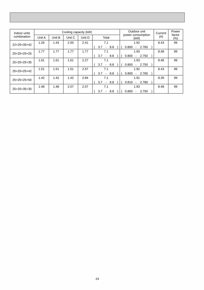
24
Indoor unitscombination
Cooling capacity (kW) Outdoor unitpower consumption
(kW)
Current(A)
Powerfactor(%)Unit A Unit B Unit C Unit D Total
22+25+35+421.26 1.43 2.00 2.41 7.1 1.92 8.43 99
( 3.7 - 8.8 ) ( 0.800 - 2.760 )
25+25+25+251.77 1.77 1.77 1.77 7.1 1.93 8.48 99
( 3.7 - 8.8 ) ( 0.800 - 2.750 )
25+25+25+351.61 1.61 1.61 2.27 7.1 1.93 8.48 99
( 3.7 - 8.8 ) ( 0.800 - 2.750 )
25+25+25+421.51 1.51 1.51 2.57 7.1 1.92 8.43 99
( 3.7 - 8.8 ) ( 0.800 - 2.760 )
25+25+25+501.42 1.42 1.42 2.84 7.1 1.91 8.39 99
( 3.7 - 8.8 ) ( 0.810 - 2.780 )
25+25+35+351.48 1.48 2.07 2.07 7.1 1.93 8.48 99
( 3.7 - 8.8 ) ( 0.800 - 2.750 )
25
Indoor unitscombination
Heating capacity (kW) Outdoor unitpower consumption
(kW)
Current(A)
Powerfactor(%)Unit A Unit B Unit C Unit D Total
223.3 - - - 3.3 0.820 3.60 99
( 1.2 - 4.2 ) ( 0.380 - 1.090 )
253.6 - - - 3.6 0.910 4.00 99
( 1.2 - 4.5 ) ( 0.380 - 1.190 )
354.0 - - - 4.0 1.040 4.57 99
( 1.2 - 4.8 ) ( 0.380 - 1.300 )
425.4 - - - 5.4 1.460 6.41 99
( 1.3 - 6.5 ) ( 0.370 - 1.800 )
507.2 - - - 7.2 1.880 8.26 99
( 1.4 - 8.2 ) ( 0.370 - 2.300 )
607.9 - - - 7.9 2.150 9.44 99
( 1.4 - 8.6 ) ( 0.360 - 2.410 )
22+223.3 3.3 - - 6.6 1.500 6.59 99
( 1.8 - 7.2 ) ( 0.410 - 1.710 )
22+253.23 3.67 - - 6.9 1.610 7.07 99
( 1.8 - 8.7 ) ( 0.410 - 2.350 )
22+352.82 4.48 - - 7.3 1.770 7.77 99
( 1.8 - 9.0 ) ( 0.410 - 2.390 )
22+423.26 5.34 - - 8.6 1.940 8.52 99
( 1.8 - 9.0 ) ( 0.400 - 2.300 )
22+502.63 5.97 - - 8.6 2.110 9.27 99
( 1.8 - 9.0 ) ( 0.390 - 2.220 )
22+602.31 6.29 - - 8.6 2.090 9.18 99
( 1.8 - 9.0 ) ( 0.380 - 2.220 )
25+253.6 3.6 - - 7.2 1.710 7.51 99
( 1.8 - 9.0 ) ( 0.410 - 2.390 )
25+353.17 4.43 - - 7.6 1.890 8.30 99
( 1.8 - 9.0 ) ( 0.410 - 2.390 )
25+423.21 5.39 - - 8.6 2.000 8.78 99
( 1.8 - 9.0 ) ( 0.400 - 2.300 )
25+502.87 5.73 - - 8.6 2.110 9.27 99
( 1.8 - 9.0 ) ( 0.390 - 2.220 )
25+602.53 6.07 - - 8.6 2.090 9.18 99
( 1.8 - 9.0 ) ( 0.380 - 2.220 )
35+354.3 4.3 - - 8.6 2.030 8.92 99
( 1.8 - 9.0 ) ( 0.410 - 2.390 )
35+423.91 4.69 - - 8.6 2.070 9.09 99
( 1.8 - 9.0 ) ( 0.400 - 2.300 )
35+503.54 5.06 - - 8.6 2.110 9.27 99
( 1.8 - 9.0 ) ( 0.390 - 2.220 )
35+603.17 5.43 - - 8.6 2.090 9.18 99
( 1.8 - 9.0 ) ( 0.380 - 2.220 )
42+424.3 4.3 - - 8.6 2.090 9.18 99
( 1.8 - 9.0 ) ( 0.400 - 2.300 )
42+503.9 4.7 - - 8.6 2.110 9.27 99
( 1.8 - 9.0 ) ( 0.390 - 2.220 )
42+603.5 5.1 - - 8.6 2.090 9.18 99
( 1.8 - 9.0 ) ( 0.380 - 2.220 )
50+504.3 4.3 - - 8.6 1.820 7.99 99
( 1.9 - 9.0 ) ( 0.360 - 2.040 )
50+603.91 4.69 - - 8.6 1.820 7.99 99
( 1.9 - 9.0 ) ( 0.360 - 2.040 )
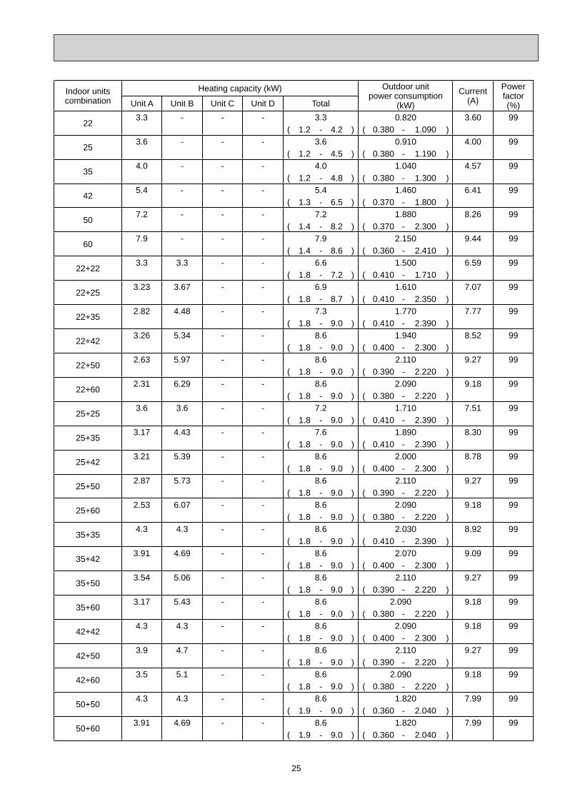
26
Indoor unitscombination
Heating capacity (kW) Outdoor unitpower consumption
(kW)
Current(A)
Powerfactor(%)Unit A Unit B Unit C Unit D Total
60+604.3 4.3 - - 8.6 1.820 7.99 99
( 1.9 - 9.0 ) ( 0.360 - 2.040 )
22+22+222.87 2.87 2.87 - 8.6 2.020 8.87 99
( 2.6 - 9.0 ) ( 0.500 - 2.120 )
22+22+252.74 2.74 3.12 - 8.6 2.020 8.87 99
( 2.6 - 9.0 ) ( 0.500 - 2.120 )
22+22+352.39 2.39 3.82 - 8.6 2.020 8.87 99
( 2.6 - 9.0 ) ( 0.500 - 2.120 )
22+22+422.2 2.2 4.2 - 8.6 1.940 8.52 99
( 2.6 - 9.0 ) ( 0.490 - 2.040 )
22+22+502.01 2.01 4.58 - 8.6 1.860 8.17 99
( 2.6 - 9.0 ) ( 0.480 - 1.960 )
22+22+601.82 1.82 4.96 - 8.6 1.850 8.12 99
( 2.6 - 9.0 ) ( 0.480 - 1.960 )
22+25+252.62 2.99 2.99 - 8.6 2.020 8.87 99
( 2.6 - 9.0 ) ( 0.500 - 2.120 )
22+25+352.31 2.62 3.67 - 8.6 2.020 8.87 99
( 2.6 - 9.0 ) ( 0.500 - 2.120 )
22+25+422.12 2.42 4.06 - 8.6 1.940 8.52 99
( 2.6 - 9.0 ) ( 0.490 - 2.040 )
22+25+501.95 2.22 4.43 - 8.6 1.860 8.17 99
( 2.6 - 9.0 ) ( 0.480 - 1.960 )
22+25+601.77 2.01 4.82 - 8.6 1.850 8.12 99
( 2.6 - 9.0 ) ( 0.480 - 1.960 )
22+35+352.06 3.27 3.27 - 8.6 2.020 8.87 99
( 2.6 - 9.0 ) ( 0.500 - 2.120 )
22+35+421.91 3.04 3.65 - 8.6 1.940 8.52 99
( 2.6 - 9.0 ) ( 0.490 - 2.040 )
22+35+501.77 2.81 4.02 - 8.6 1.860 8.17 99
( 2.6 - 9.0 ) ( 0.480 - 1.960 )
22+35+601.62 2.57 4.41 - 8.6 1.850 8.12 99
( 2.6 - 9.0 ) ( 0.480 - 1.960 )
22+42+421.8 3.4 3.4 - 8.6 1.940 8.52 99
( 2.6 - 9.0 ) ( 0.490 - 2.040 )
22+42+501.66 3.17 3.77 - 8.6 1.860 8.17 99
( 2.6 - 9.0 ) ( 0.480 - 1.960 )
22+42+601.5 2.9 4.2 - 8.6 1.850 8.12 99
( 2.6 - 9.0 ) ( 0.480 - 1.960 )
22+50+501.56 3.52 3.52 - 8.6 1.670 7.33 99
( 2.6 - 9.0 ) ( 0.460 - 1.830 )
25+25+252.86 2.86 2.86 - 8.6 2.020 8.87 99
( 2.6 - 9.0 ) ( 0.500 - 2.120 )
25+25+352.53 2.53 3.54 - 8.6 2.020 8.87 99
( 2.6 - 9.0 ) ( 0.500 - 2.120 )
25+25+422.33 2.33 3.94 - 8.6 1.940 8.52 99
( 2.6 - 9.0 ) ( 0.490 - 2.040 )
25+25+502.15 2.15 4.30 - 8.6 1.860 8.17 99
( 2.6 - 9.0 ) ( 0.480 - 1.960 )
25+25+601.95 1.95 4.68 - 8.6 1.850 8.12 99
( 2.6 - 9.0 ) ( 0.480 - 1.960 )
25+35+352.26 3.17 3.17 - 8.6 2.020 8.87 99
( 2.6 - 9.0 ) ( 0.500 - 2.120 )
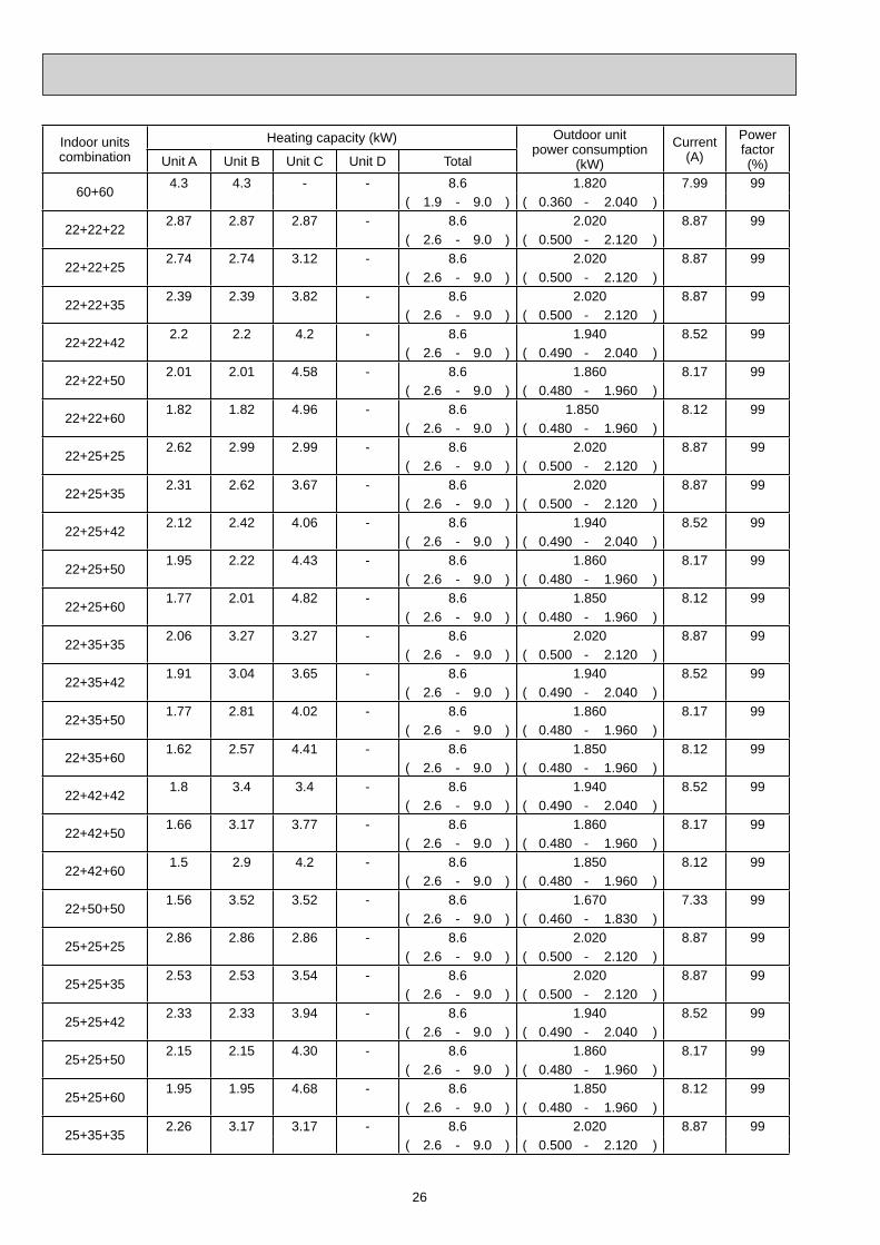
27
Indoor unitscombination
Heating capacity (kW) Outdoor unitpower consumption
(kW)
Current(A)
Powerfactor(%)Unit A Unit B Unit C Unit D Total
25+35+422.11 2.95 3.54 - 8.6 1.940 8.52 99
( 2.6 - 9.0 ) ( 0.490 - 2.040 )
25+35+501.95 2.74 3.91 - 8.6 1.860 8.17 99
( 2.6 - 9.0 ) ( 0.480 - 1.960 )
25+35+601.79 2.51 4.30 - 8.6 1.850 8.12 99
( 2.6 - 9.0 ) ( 0.480 - 1.960 )
25+42+422.0 3.3 3.3 - 8.6 1.940 8.52 99
( 2.6 - 9.0 ) ( 0.490 - 2.040 )
25+42+501.8 3.1 3.7 - 8.6 1.860 8.17 99
( 2.6 - 9.0 ) ( 0.480 - 1.960 )
25+50+501.72 3.44 3.44 - 8.6 1.670 7.33 99
( 2.6 - 9.0 ) ( 0.460 - 1.830 )
35+35+352.86 2.86 2.86 - 8.6 2.020 8.87 99
( 2.6 - 9.0 ) ( 0.500 - 2.120 )
35+35+422.68 2.68 3.24 - 8.6 1.940 8.52 99
( 2.6 - 9.0 ) ( 0.500 - 2.040 )
35+35+502.51 2.51 3.58 - 8.6 1.860 8.17 99
( 2.6 - 9.0 ) ( 0.500 - 1.960 )
35+42+422.52 3.04 3.04 - 8.6 1.940 8.52 99
( 2.6 - 9.0 ) ( 0.490 - 2.040 )
22+22+22+222.15 2.15 2.15 2.15 8.6 1.950 8.56 99
( 3.4 - 9.0 ) ( 0.600 - 1.960 )
22+22+22+252.08 2.08 2.08 2.36 8.6 1.950 8.56 99
( 3.4 - 9.0 ) ( 0.600 - 1.960 )
22+22+22+351.87 1.87 1.87 2.98 8.6 1.950 8.56 99
( 3.4 - 9.0 ) ( 0.600 - 1.960 )
22+22+22+421.75 1.75 1.75 3.35 8.6 1.860 8.17 99
( 3.4 - 9.0 ) ( 0.600 - 1.940 )
22+22+22+501.63 1.63 1.63 3.71 8.6 1.770 7.77 99
( 3.4 - 9.0 ) ( 0.600 - 1.930 )
22+22+25+252.01 2.01 2.29 2.29 8.6 1.950 8.56 99
( 3.4 - 9.0 ) ( 0.600 - 1.960 )
22+22+25+351.82 1.82 2.07 2.89 8.6 1.950 8.56 99
( 3.4 - 9.0 ) ( 0.600 - 1.960 )
22+22+25+421.70 1.70 1.94 3.26 8.6 1.860 8.17 99
( 3.4 - 9.0 ) ( 0.600 - 1.940 )
22+22+25+501.59 1.59 1.81 3.61 8.6 1.770 7.77 99
( 3.4 - 9.0 ) ( 0.600 - 1.930 )
22+22+35+351.66 1.66 2.64 2.64 8.6 1.950 8.56 99
( 3.4 - 9.0 ) ( 0.600 - 1.960 )
22+22+35+421.56 1.56 2.49 2.99 8.6 1.860 8.17 99
( 3.4 - 9.0 ) ( 0.600 - 1.940 )
22+25+25+251.94 2.22 2.22 2.22 8.6 1.950 8.56 99
( 3.4 - 9.0 ) ( 0.600 - 1.960 )
22+25+25+351.77 2.01 2.01 2.81 8.6 1.950 8.56 99
( 3.4 - 9.0 ) ( 0.600 - 1.960 )
22+25+25+421.65 1.89 1.89 3.17 8.6 1.860 8.17 99
( 3.4 - 9.0 ) ( 0.600 - 1.940 )
22+25+25+501.56 1.76 1.76 3.52 8.6 1.770 7.77 99
( 3.4 - 9.0 ) ( 0.600 - 1.930 )
22+25+35+351.62 1.84 2.57 2.57 8.6 1.950 8.56 99
( 3.4 - 9.0 ) ( 0.600 - 1.960 )

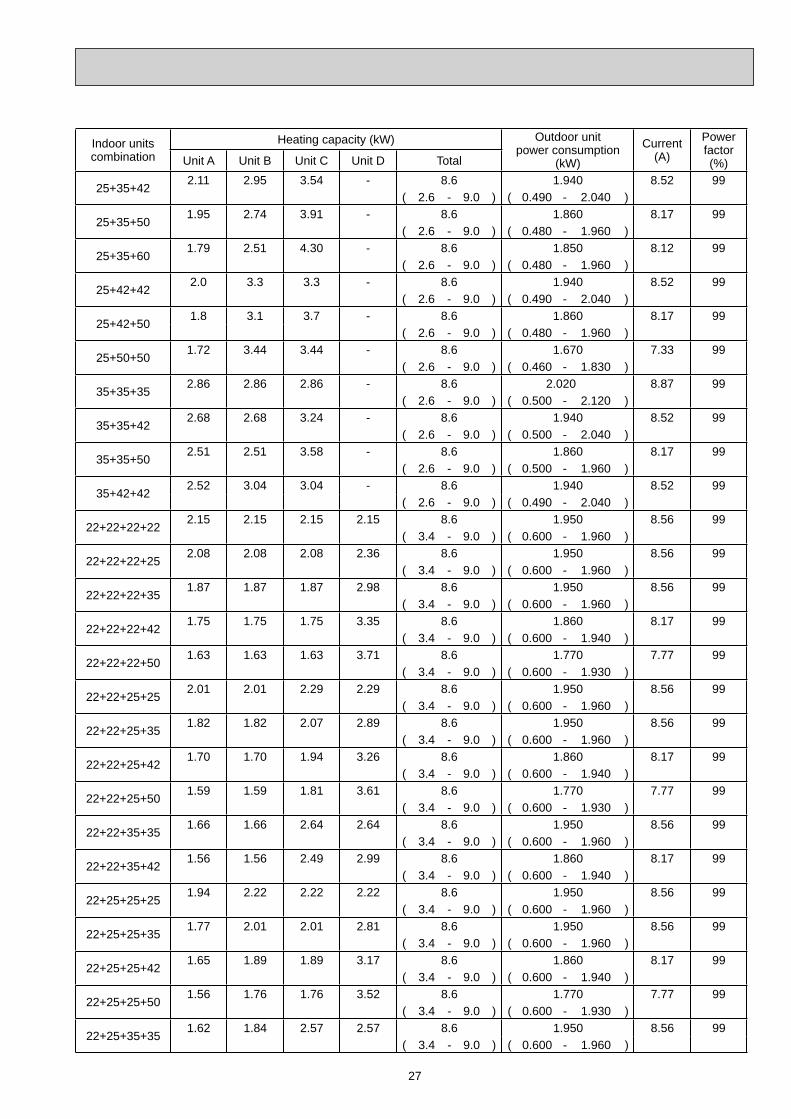
28
Indoor unitscombination
Heating capacity (kW) Outdoor unitpower consumption
(kW)
Current(A)
Powerfactor(%)Unit A Unit B Unit C Unit D Total
22+25+35+421.53 1.73 2.43 2.91 8.6 1.860 8.17 99
( 3.4 - 9.0 ) ( 0.600 - 1.940 )
25+25+25+252.15 2.15 2.15 2.15 8.6 1.950 8.56 99
( 3.4 - 9.0 ) ( 0.600 - 1.960 )
25+25+25+351.95 1.95 1.95 2.75 8.6 1.950 8.56 99
( 3.4 - 9.0 ) ( 0.600 - 1.960 )
25+25+25+421.83 1.83 1.83 3.11 8.6 1.860 8.17 99
( 3.4 - 9.0 ) ( 0.600 - 1.940 )
25+25+25+501.72 1.72 1.72 3.44 8.6 1.770 7.77 99
( 3.4 - 9.0 ) ( 0.600 - 1.930 )
25+25+35+351.79 1.79 2.51 2.51 8.6 1.950 8.56 99
( 3.4 - 9.0 ) ( 0.600 - 1.960 )
29
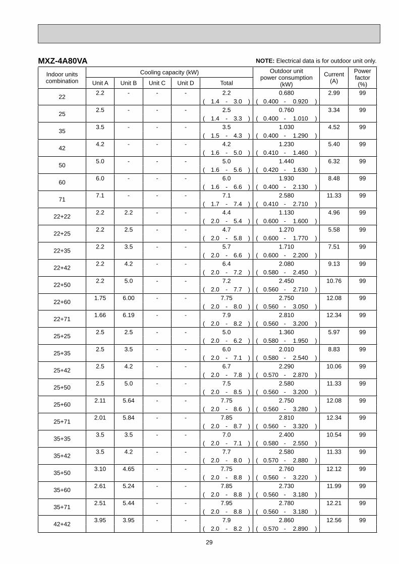
MXZ-4A80VA NOTE: Electrical data is for outdoor unit only.
Indoor unitscombination
Cooling capacity (kW) Outdoor unitpower consumption
(kW)
Current(A)
Powerfactor(%)Unit A Unit B Unit C Unit D Total
222.2 - - - 2.2 0.680 2.99 99
( 1.4 - 3.0 ) ( 0.400 - 0.920 )
252.5 - - - 2.5 0.760 3.34 99
( 1.4 - 3.3 ) ( 0.400 - 1.010 )
353.5 - - - 3.5 1.030 4.52 99
( 1.5 - 4.3 ) ( 0.400 - 1.290 )
424.2 - - - 4.2 1.230 5.40 99
( 1.6 - 5.0 ) ( 0.410 - 1.460 )
505.0 - - - 5.0 1.440 6.32 99
( 1.6 - 5.6 ) ( 0.420 - 1.630 )
606.0 - - - 6.0 1.930 8.48 99
( 1.6 - 6.6 ) ( 0.400 - 2.130 )
717.1 - - - 7.1 2.580 11.33 99
( 1.7 - 7.4 ) ( 0.410 - 2.710 )
22+222.2 2.2 - - 4.4 1.130 4.96 99
( 2.0 - 5.4 ) ( 0.600 - 1.600 )
22+252.2 2.5 - - 4.7 1.270 5.58 99
( 2.0 - 5.8 ) ( 0.600 - 1.770 )
22+352.2 3.5 - - 5.7 1.710 7.51 99
( 2.0 - 6.6 ) ( 0.600 - 2.200 )
22+422.2 4.2 - - 6.4 2.080 9.13 99
( 2.0 - 7.2 ) ( 0.580 - 2.450 )
22+502.2 5.0 - - 7.2 2.450 10.76 99
( 2.0 - 7.7 ) ( 0.560 - 2.710 )
22+601.75 6.00 - - 7.75 2.750 12.08 99
( 2.0 - 8.0 ) ( 0.560 - 3.050 )
22+711.66 6.19 - - 7.9 2.810 12.34 99
( 2.0 - 8.2 ) ( 0.560 - 3.200 )
25+252.5 2.5 - - 5.0 1.360 5.97 99
( 2.0 - 6.2 ) ( 0.580 - 1.950 )
25+352.5 3.5 - - 6.0 2.010 8.83 99
( 2.0 - 7.1 ) ( 0.580 - 2.540 )
25+422.5 4.2 - - 6.7 2.290 10.06 99
( 2.0 - 7.8 ) ( 0.570 - 2.870 )
25+502.5 5.0 - - 7.5 2.580 11.33 99
( 2.0 - 8.5 ) ( 0.560 - 3.200 )
25+602.11 5.64 - - 7.75 2.750 12.08 99
( 2.0 - 8.6 ) ( 0.560 - 3.280 )
25+712.01 5.84 - - 7.85 2.810 12.34 99
( 2.0 - 8.7 ) ( 0.560 - 3.320 )
35+353.5 3.5 - - 7.0 2.400 10.54 99
( 2.0 - 7.1 ) ( 0.580 - 2.550 )
35+423.5 4.2 - - 7.7 2.580 11.33 99
( 2.0 - 8.0 ) ( 0.570 - 2.880 )
35+503.10 4.65 - - 7.75 2.760 12.12 99
( 2.0 - 8.8 ) ( 0.560 - 3.220 )
35+602.61 5.24 - - 7.85 2.730 11.99 99
( 2.0 - 8.8 ) ( 0.560 - 3.180 )
35+712.51 5.44 - - 7.95 2.780 12.21 99
( 2.0 - 8.8 ) ( 0.560 - 3.180 )
42+423.95 3.95 - - 7.9 2.860 12.56 99
( 2.0 - 8.2 ) ( 0.570 - 2.890 )
30
Indoor unitscombination
Cooling capacity (kW) Outdoor unitpower consumption
(kW)
Current(A)
Powerfactor(%)Unit A Unit B Unit C Unit D Total
42+503.6 4.3 - - 7.9 2.860 12.56 99
( 2.0 - 8.8 ) ( 0.560 - 3.190 )
42+603.3 4.7 - - 8.0 2.880 12.65 99
( 2.0 - 8.8 ) ( 0.560 - 3.150 )
42+713.0 5.0 - - 8.0 2.880 12.65 99
( 2.0 - 8.8 ) ( 0.560 - 3.150 )
50+503.95 3.95 - - 7.9 2.780 12.21 99
( 2.1 - 8.8 ) ( 0.590 - 3.160 )
50+603.43 4.57 - - 8.0 2.800 12.30 99
( 2.1 - 8.8 ) ( 0.570 - 3.120 )
50+713.27 4.73 - - 8.0 2.800 12.30 99
( 2.1 - 8.8 ) ( 0.570 - 3.120 )
60+604.00 4.00 - - 8.0 2.690 11.81 99
( 2.1 - 8.8 ) ( 0.550 - 3.080 )
60+713.84 4.16 - - 8.0 2.690 11.81 99
( 2.1 - 8.8 ) ( 0.550 - 3.080 )
22+22+222.2 2.2 2.2 - 6.6 1.860 8.17 99
( 2.9 - 8.1 ) ( 0.690 - 2.410 )
22+22+252.2 2.2 2.5 - 6.9 1.970 8.65 99
( 2.9 - 8.3 ) ( 0.670 - 2.510 )
22+22+352.14 2.14 3.42 - 7.7 2.310 10.14 99
( 2.9 - 8.3 ) ( 0.690 - 2.970 )
22+22+422.01 2.01 3.83 - 7.85 2.310 10.14 99
( 2.9 - 8.7 ) ( 0.690 - 2.940 )
22+22+501.72 1.72 4.41 - 7.85 2.320 10.19 99
( 2.9 - 9.0 ) ( 0.700 - 2.920 )
22+22+601.46 1.46 5.03 - 7.95 2.370 10.41 99
( 2.9 - 9.0 ) ( 0.680 - 2.880 )
22+22+711.4 1.4 5.2 - 8.0 2.390 10.50 99
( 2.9 - 9.0 ) ( 0.680 - 2.880 )
22+25+252.2 2.5 2.5 - 7.2 2.100 9.22 99
( 2.9 - 8.9 ) ( 0.690 - 2.940 )
22+25+352.08 2.36 3.31 - 7.75 2.350 10.32 99
( 2.9 - 8.9 ) ( 0.690 - 2.970 )
22+25+421.95 2.22 3.73 - 7.9 2.360 10.36 99
( 2.9 - 9.0 ) ( 0.690 - 2.940 )
22+25+501.79 2.04 4.07 - 7.9 2.370 10.41 99
( 2.9 - 9.0 ) ( 0.700 - 2.920 )
22+25+601.64 1.87 4.49 - 8.0 2.390 10.50 99
( 2.9 - 9.0 ) ( 0.680 - 2.880 )
22+25+711.49 1.69 4.82 - 8.0 2.390 10.50 99
( 2.9 - 9.0 ) ( 0.680 - 2.880 )
22+35+351.87 2.99 2.99 - 7.85 2.350 10.32 99
( 2.9 - 9.0 ) ( 0.690 - 2.920 )
22+35+421.76 2.79 3.35 - 7.9 2.330 10.23 99
( 2.9 - 9.0 ) ( 0.690 - 2.900 )
22+35+501.63 2.58 3.69 - 7.9 2.320 10.19 99
( 2.9 - 9.0 ) ( 0.700 - 2.890 )
22+35+601.5 2.4 4.1 - 8.0 2.350 10.32 99
( 2.9 - 9.0 ) ( 0.680 - 2.860 )
22+35+711.38 2.18 4.44 - 8.0 2.350 10.32 99
( 2.9 - 9.0 ) ( 0.680 - 2.860 )

31
Indoor unitscombination
Cooling capacity (kW) Outdoor unitpower consumption
(kW)
Current(A)
Powerfactor(%)Unit A Unit B Unit C Unit D Total
22+42+421.65 3.15 3.15 - 7.95 2.300 10.10 99
( 2.9 - 9.0 ) ( 0.680 - 2.880 )
22+42+501.53 2.93 3.49 - 7.95 2.290 10.06 99
( 2.9 - 9.0 ) ( 0.690 - 2.870 )
22+42+601.4 2.7 3.9 - 8.0 2.320 10.19 99
( 2.9 - 9.0 ) ( 0.670 - 2.840 )
22+42+711.3 2.5 4.2 - 8.0 2.320 10.19 99
( 2.9 - 9.0 ) ( 0.670 - 2.840 )
22+50+501.44 3.28 3.28 - 8.0 2.330 10.23 99
( 2.9 - 9.0 ) ( 0.680 - 2.860 )
22+50+601.33 3.03 3.64 - 8.0 2.300 10.10 99
( 2.9 - 9.0 ) ( 0.660 - 2.830 )
22+50+711.23 2.80 3.97 - 8.0 2.300 10.10 99
( 2.9 - 9.0 ) ( 0.660 - 2.830 )
25+25+252.5 2.5 2.5 - 7.5 2.250 9.88 99
( 2.9 - 9.0 ) ( 0.690 - 3.010 )
25+25+352.28 2.28 3.19 - 7.75 2.350 10.32 99
( 2.9 - 9.0 ) ( 0.690 - 2.970 )
25+25+422.14 2.14 3.62 - 7.9 2.360 10.36 99
( 2.9 - 9.0 ) ( 0.690 - 2.940 )
25+25+501.98 1.98 3.94 - 7.9 2.370 10.41 99
( 2.9 - 9.0 ) ( 0.700 - 2.920 )
25+25+601.82 1.82 4.36 - 8.0 2.390 10.50 99
( 2.9 - 9.0 ) ( 0.680 - 2.880 )
25+25+711.65 1.65 4.70 - 8.0 2.390 10.50 99
( 2.9 - 9.0 ) ( 0.680 - 2.880 )
25+35+352.07 2.89 2.89 - 7.85 2.350 10.32 99
( 2.9 - 9.0 ) ( 0.690 - 2.920 )
25+35+421.96 2.75 3.29 - 8.0 2.360 10.36 99
( 2.9 - 9.0 ) ( 0.690 - 2.900 )
25+35+501.82 2.54 3.64 - 8.0 2.380 10.45 99
( 2.9 - 9.0 ) ( 0.700 - 2.890 )
25+35+601.67 2.33 4.00 - 8.0 2.350 10.32 99
( 2.9 - 9.0 ) ( 0.680 - 2.860 )
25+35+711.53 2.14 4.33 - 8.0 2.350 10.32 99
( 2.9 - 9.0 ) ( 0.680 - 2.860 )
25+42+421.8 3.1 3.1 - 8.0 2.330 10.23 99
( 2.9 - 9.0 ) ( 0.670 - 2.870 )
25+42+501.7 2.9 3.4 - 8.0 2.350 10.32 99
( 2.9 - 9.0 ) ( 0.680 - 2.860 )
25+42+601.6 2.6 3.8 - 8.0 2.320 10.19 99
( 2.9 - 9.0 ) ( 0.670 - 2.840 )
25+42+711.45 2.43 4.12 - 8.0 2.320 10.19 99
( 2.9 - 9.0 ) ( 0.670 - 2.840 )
25+50+501.6 3.2 3.2 - 8.0 2.330 10.23 99
( 2.9 - 9.0 ) ( 0.660 - 2.840 )
25+50+601.48 2.96 3.56 - 8.0 2.300 10.10 99
( 2.9 - 9.0 ) ( 0.660 - 2.830 )
35+35+352.65 2.65 2.65 - 7.95 2.280 10.01 99
( 2.9 - 9.0 ) ( 0.720 - 2.910 )
35+35+422.5 2.5 3.0 - 8.0 2.270 9.97 99
( 2.9 - 9.0 ) ( 0.710 - 2.890 )

32
Indoor unitscombination
Cooling capacity (kW) Outdoor unitpower consumption
(kW)
Current(A)
Powerfactor(%)Unit A Unit B Unit C Unit D Total
35+35+502.33 2.33 3.34 - 8.0 2.260 9.93 99
( 2.9 - 9.0 ) ( 0.700 - 2.870 )
35+35+602.15 2.15 3.70 - 8.0 2.260 9.93 99
( 2.9 - 9.0 ) ( 0.680 - 2.840 )
35+35+711.99 1.99 4.02 - 8.0 2.260 9.93 99
( 2.9 - 9.0 ) ( 0.680 - 2.840 )
35+42+422.4 2.8 2.8 - 8.0 2.260 9.93 99
( 2.9 - 9.0 ) ( 0.700 - 2.870 )
35+42+502.20 2.65 3.15 - 8.0 2.250 9.88 99
( 2.9 - 9.0 ) ( 0.690 - 2.850 )
35+42+602.0 2.5 3.5 - 8.0 2.240 9.84 99
( 2.9 - 9.0 ) ( 0.670 - 2.820 )
35+50+502.08 2.96 2.96 - 8.0 2.240 9.84 99
( 2.9 - 9.0 ) ( 0.680 - 2.840 )
35+50+601.93 2.76 3.31 - 8.0 2.220 9.75 99
( 2.9 - 9.0 ) ( 0.660 - 2.810 )
22+22+22+221.95 1.95 1.95 1.95 7.8 2.180 9.57 99
( 3.7 - 9.2 ) ( 0.810 - 2.670 )
22+22+22+251.90 1.90 1.90 2.15 7.85 2.190 9.62 99
( 3.7 - 9.2 ) ( 0.810 - 2.670 )
22+22+22+351.73 1.73 1.73 2.76 7.95 2.210 9.71 99
( 3.7 - 9.2 ) ( 0.810 - 2.650 )
22+22+22+421.63 1.63 1.63 3.11 8.0 2.180 9.57 99
( 3.7 - 9.2 ) ( 0.800 - 2.630 )
22+22+22+501.52 1.52 1.52 3.44 8.0 2.150 9.44 99
( 3.7 - 9.2 ) ( 0.790 - 2.620 )
22+22+22+601.4 1.4 1.4 3.8 8.0 2.130 9.35 99
( 3.7 - 9.2 ) ( 0.770 - 2.590 )
22+22+22+711.28 1.28 1.28 4.16 8.0 2.130 9.35 99
( 3.7 - 9.2 ) ( 0.770 - 2.590 )
22+22+25+251.87 1.87 2.13 2.13 8.0 2.190 9.62 99
( 3.7 - 9.2 ) ( 0.810 - 2.670 )
22+22+25+351.68 1.68 1.91 1.91 7.18 2.210 9.71 99
( 3.7 - 9.2 ) ( 0.810 - 2.650 )
22+22+25+421.58 1.58 1.80 3.04 8.0 2.180 9.57 99
( 3.7 - 9.2 ) ( 0.800 - 2.630 )
22+22+25+501.48 1.48 1.68 3.36 8.0 2.150 9.44 99
( 3.7 - 9.2 ) ( 0.790 - 2.620 )
22+22+25+601.36 1.36 1.55 3.73 8.0 2.130 9.35 99
( 3.7 - 9.2 ) ( 0.770 - 2.590 )
22+22+25+711.26 1.26 1.43 4.05 8.0 2.130 9.35 99
( 3.7 - 9.2 ) ( 0.770 - 2.590 )
22+22+35+351.54 1.54 2.46 2.46 8.0 2.210 9.71 99
( 3.7 - 9.2 ) ( 0.810 - 2.620 )
22+22+35+421.45 1.45 2.31 2.79 8.0 2.160 9.49 99
( 3.7 - 9.2 ) ( 0.800 - 2.600 )
22+22+35+501.36 1.36 2.18 3.10 8.0 2.120 9.31 99
( 3.7 - 9.2 ) ( 0.790 - 2.590 )
22+22+35+601.12 1.12 1.92 3.84 8.0 2.100 9.22 99
( 3.7 - 9.2 ) ( 0.770 - 2.560 )
22+22+42+421.4 1.4 2.6 2.6 8.0 2.130 9.35 99
( 3.7 - 9.2 ) ( 0.790 - 2.580 )

33
Indoor unitscombination
Cooling capacity (kW) Outdoor unitpower consumption
(kW)
Current(A)
Powerfactor(%)Unit A Unit B Unit C Unit D Total
22+22+42+501.3 1.3 2.5 2.9 8.0 2.090 9.18 99
( 3.7 - 9.2 ) ( 0.780 - 2.570 )
22+22+50+501.22 1.22 2.78 2.78 8.0 2.070 9.09 99
( 3.7 - 9.2 ) ( 0.770 - 2.560 )
22+25+25+251.78 2.04 2.04 2.04 7.9 2.140 9.40 99
( 3.7 - 9.2 ) ( 0.810 - 2.670 )
22+25+25+351.63 1.86 1.86 2.60 7.95 2.210 9.71 99
( 3.7 - 9.2 ) ( 0.810 - 2.650 )
22+25+25+421.54 1.75 1.75 2.96 8.0 2.180 9.57 99
( 3.7 - 9.2 ) ( 0.800 - 2.630 )
22+25+25+501.44 1.64 1.64 3.28 8.0 2.150 9.44 99
( 3.7 - 9.2 ) ( 0.790 - 2.620 )
22+25+25+601.33 1.52 1.52 3.64 8.0 2.130 9.35 99
( 3.7 - 9.2 ) ( 0.770 - 2.590 )
22+25+35+351.51 1.71 2.39 2.39 8.0 2.210 9.71 99
( 3.7 - 9.2 ) ( 0.810 - 2.620 )
22+25+35+421.42 1.61 2.26 2.71 8.0 2.160 9.49 99
( 3.7 - 9.2 ) ( 0.800 - 2.600 )
22+25+35+501.33 1.52 2.12 3.03 8.0 2.120 9.31 99
( 3.7 - 9.2 ) ( 0.790 - 2.590 )
22+25+35+601.24 1.41 1.97 3.38 8.0 2.100 9.22 99
( 3.7 - 9.2 ) ( 0.770 - 2.560 )
22+35+35+351.4 2.2 2.2 2.2 8.0 2.200 9.66 99
( 3.7 - 9.2 ) ( 0.810 - 2.610 )
22+35+35+421.31 2.09 2.09 2.51 8.0 2.140 9.40 99
( 3.7 - 9.2 ) ( 0.800 - 2.600 )
22+35+35+501.24 1.97 1.97 2.82 8.0 2.080 9.13 99
( 3.7 - 9.2 ) ( 0.790 - 2.590 )
22+35+42+421.2 2.0 2.4 2.4 8.0 2.080 9.13 99
( 3.7 - 9.2 ) ( 0.790 - 2.590 )
25+25+25+251.98 1.98 1.98 1.98 7.92 2.150 9.44 99
( 3.7 - 9.2 ) ( 0.810 - 2.670 )
25+25+25+351.82 1.82 1.82 2.54 8.0 2.220 9.75 99
( 3.7 - 9.2 ) ( 0.810 - 2.650 )
25+25+25+421.71 1.71 1.71 2.87 8.0 2.180 9.57 99
( 3.7 - 9.2 ) ( 0.800 - 2.630 )
25+25+25+501.6 1.6 1.6 3.2 8.0 2.150 9.44 99
( 3.7 - 9.2 ) ( 0.790 - 2.620 )
25+25+25+601.48 1.48 1.48 3.56 8.0 2.130 9.35 99
( 3.7 - 9.2 ) ( 0.770 - 2.590 )
25+25+35+351.67 1.67 2.33 2.33 8.0 2.210 9.71 99
( 3.7 - 9.2 ) ( 0.810 - 2.620 )
25+25+35+421.57 1.57 2.20 2.66 8.0 2.160 9.49 99
( 3.7 - 9.2 ) ( 0.800 - 2.600 )
25+25+35+501.48 1.48 2.08 2.96 8.0 2.120 9.31 99
( 3.7 - 9.2 ) ( 0.790 - 2.590 )
25+35+35+351.55 2.15 2.15 2.15 8.0 2.200 9.66 99
( 3.7 - 9.2 ) ( 0.810 - 2.610 )
25+35+35+421.46 2.04 2.04 2.46 8.0 2.150 9.44 99
( 3.7 - 9.2 ) ( 0.800 - 2.590 )
35+35+35+352.0 2.0 2.0 2.0 8.0 2.190 9.62 99
( 3.7 - 9.2 ) ( 0.810 - 2.580 )

34
Indoor unitscombination
Heating capacity (kW) Outdoor unitpower consumption
(kW)
Current(A)
Powerfactor(%)Unit A Unit B Unit C Unit D Total
223.3 - - - 3.3 1.050 4.61 99
( 1.3 - 4.2 ) ( 0.340 - 1.380 )
253.6 - - - 3.6 1.110 4.87 99
( 1.2 - 4.5 ) ( 0.340 - 1.510 )
354.0 - - - 4.0 1.210 5.31 99
( 1.2 - 4.8 ) ( 0.330 - 1.570 )
425.4 - - - 5.4 1.990 8.74 99
( 1.3 - 6.5 ) ( 0.330 - 2.140 )
507.2 - - - 7.2 2.770 12.17 99
( 1.4 - 8.2 ) ( 0.330 - 2.710 )
607.9 - - - 7.9 2.700 11.86 99
( 1.4 - 8.6 ) ( 0.330 - 3.060 )
718.6 - - - 8.6 3.220 14.14 99
( 1.6 - 9.2 ) ( 0.360 - 3.520 )
22+223.3 3.3 - - 6.6 2.020 8.87 99
( 1.8 - 7.2 ) ( 0.480 - 2.760 )
22+253.23 3.67 - - 6.9 2.120 9.31 99
( 1.8 - 8.7 ) ( 0.480 - 3.000 )
22+352.82 4.48 - - 7.3 2.130 9.35 99
( 1.8 - 9.2 ) ( 0.480 - 3.110 )
22+422.78 5.32 - - 8.1 2.300 10.10 99
( 1.8 - 9.6 ) ( 0.470 - 3.120 )
22+502.72 6.18 - - 8.9 2.470 10.85 99
( 1.8 - 9.9 ) ( 0.460 - 3.140 )
22+602.52 6.88 - - 9.4 2.710 11.90 99
( 1.8 - 9.9 ) ( 0.460 - 3.140 )
22+712.22 7.18 - - 9.4 2.710 11.90 99
( 1.8 - 9.9 ) ( 0.460 - 3.140 )
25+253.6 3.6 - - 7.2 2.170 9.53 99
( 1.8 - 9.1 ) ( 0.480 - 3.140 )
25+353.17 4.43 - - 7.6 2.210 9.71 99
( 1.8 - 9.5 ) ( 0.480 - 3.230 )
25+423.1 5.2 - - 8.3 2.360 10.36 99
( 1.8 - 9.8 ) ( 0.470 - 3.240 )
25+503.0 6.0 - - 9.0 2.520 11.07 99
( 1.8 - 10.1 ) ( 0.460 - 3.260 )
25+602.76 6.64 - - 9.4 2.710 11.90 99
( 1.8 - 10.1 ) ( 0.460 - 3.260 )
25+712.45 6.95 - - 9.4 2.710 11.90 99
( 1.8 - 10.1 ) ( 0.460 - 3.260 )
35+354.0 4.0 - - 8.0 2.370 10.41 99
( 1.8 - 9.8 ) ( 0.480 - 3.230 )
35+423.95 4.75 - - 8.7 2.460 10.80 99
( 1.8 - 10.2 ) ( 0.470 - 3.320 )
35+503.87 5.53 - - 9.4 2.560 11.24 99
( 1.8 - 10.5 ) ( 0.460 - 3.420 )
35+603.46 5.94 - - 9.4 2.560 11.24 99
( 1.8 - 10.5 ) ( 0.460 - 3.420 )
35+713.1 6.3 - - 9.4 2.560 11.24 99
( 1.8 - 10.5 ) ( 0.460 - 3.420 )
42+424.7 4.7 - - 9.4 2.460 10.80 99
( 1.8 - 10.9 ) ( 0.470 - 3.370 )

35
Indoor unitscombination
Heating capacity (kW) Outdoor unitpower consumption
(kW)
Current(A)
Powerfactor(%)Unit A Unit B Unit C Unit D Total
42+504.3 5.1 - - 9.4 2.460 10.80 99
( 1.8 - 10.9 ) ( 0.460 - 3.370 )
42+603.9 5.5 - - 9.4 2.460 10.80 99
( 1.8 - 10.9 ) ( 0.460 - 3.370 )
42+713.5 5.9 - - 9.4 2.460 10.80 99
( 1.8 - 10.9 ) ( 0.460 - 3.370 )
50+504.7 4.7 - - 9.4 2.370 10.41 99
( 1.9 - 11.2 ) ( 0.440 - 3.320 )
50+604.3 5.1 - - 9.4 2.370 10.41 99
( 1.9 - 11.2 ) ( 0.440 - 3.320 )
50+713.88 5.52 - - 9.4 2.370 10.41 99
( 1.9 - 11.2 ) ( 0.440 - 3.320 )
60+604.7 4.7 - - 9.4 2.370 10.41 99
( 1.9 - 11.2 ) ( 0.440 - 3.320 )
60+714.31 5.09 - - 9.4 2.370 10.41 99
( 1.9 - 11.2 ) ( 0.440 - 3.320 )
22+22+222.9 2.9 2.9 - 8.7 2.150 9.44 99
( 2.6 - 10.6 ) ( 0.530 - 3.060 )
22+22+252.81 2.81 3.18 - 8.8 2.170 9.53 99
( 2.6 - 11.1 ) ( 0.530 - 3.300 )
22+22+352.62 2.62 4.16 - 9.4 2.310 10.14 99
( 2.6 - 11.6 ) ( 0.530 - 3.400 )
22+22+422.4 2.4 4.6 - 9.4 2.210 9.71 99
( 2.6 - 11.6 ) ( 0.520 - 3.360 )
22+22+502.2 2.2 5.0 - 9.4 2.120 9.31 99
( 2.6 - 11.6 ) ( 0.510 - 3.330 )
22+22+601.99 1.99 5.42 - 9.4 2.120 9.31 99
( 2.6 - 11.6 ) ( 0.510 - 3.330 )
22+22+711.8 1.8 5.8 - 9.4 2.120 9.31 99
( 2.6 - 11.6 ) ( 0.510 - 3.330 )
22+25+252.72 3.09 3.09 - 8.9 2.170 9.53 99
( 2.6 - 11.6 ) ( 0.530 - 3.420 )
22+25+352.52 2.87 4.01 - 9.4 2.270 9.97 99
( 2.6 - 11.6 ) ( 0.530 - 3.410 )
22+25+422.32 2.64 4.44 - 9.4 2.180 9.57 99
( 2.6 - 11.6 ) ( 0.520 - 3.370 )
22+25+502.13 2.42 4.85 - 9.4 2.100 9.22 99
( 2.6 - 11.6 ) ( 0.510 - 3.330 )
22+25+601.93 2.20 5.27 - 9.4 2.100 9.22 99
( 2.6 - 11.6 ) ( 0.510 - 3.330 )
22+25+711.75 1.99 5.66 - 9.4 2.100 9.22 99
( 2.6 - 11.6 ) ( 0.510 - 3.330 )
22+35+352.24 3.58 3.58 - 9.4 2.210 9.71 99
( 2.6 - 11.6 ) ( 0.530 - 3.400 )
22+35+422.09 3.32 3.99 - 9.4 2.130 9.35 99
( 2.7 - 11.6 ) ( 0.520 - 3.310 )
22+35+501.93 3.07 4.39 - 9.4 2.050 9.00 99
( 2.7 - 11.6 ) ( 0.510 - 3.230 )
22+35+601.77 2.81 4.82 - 9.4 2.050 9.00 99
( 2.7 - 11.6 ) ( 0.510 - 3.230 )
22+35+711.62 2.57 5.21 - 9.4 2.050 9.00 99
( 2.7 - 11.6 ) ( 0.510 - 3.230 )
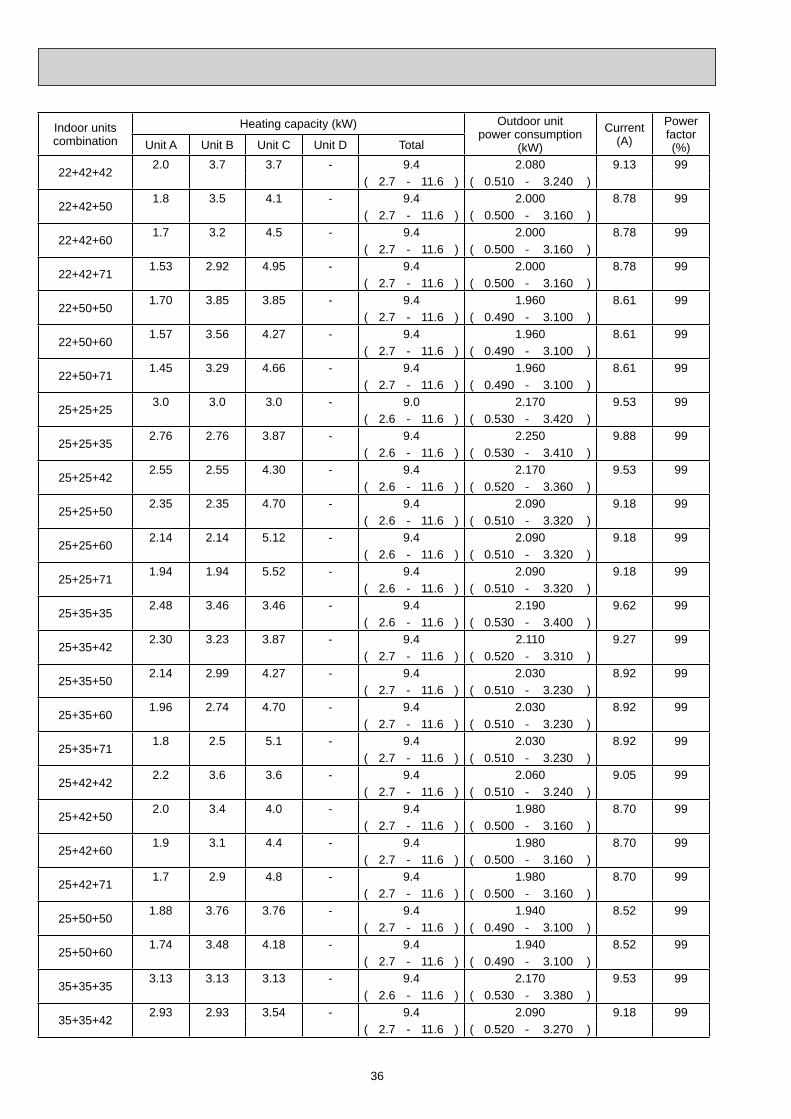
36
Indoor unitscombination
Heating capacity (kW) Outdoor unitpower consumption
(kW)
Current(A)
Powerfactor(%)Unit A Unit B Unit C Unit D Total
22+42+422.0 3.7 3.7 - 9.4 2.080 9.13 99
( 2.7 - 11.6 ) ( 0.510 - 3.240 )
22+42+501.8 3.5 4.1 - 9.4 2.000 8.78 99
( 2.7 - 11.6 ) ( 0.500 - 3.160 )
22+42+601.7 3.2 4.5 - 9.4 2.000 8.78 99
( 2.7 - 11.6 ) ( 0.500 - 3.160 )
22+42+711.53 2.92 4.95 - 9.4 2.000 8.78 99
( 2.7 - 11.6 ) ( 0.500 - 3.160 )
22+50+501.70 3.85 3.85 - 9.4 1.960 8.61 99
( 2.7 - 11.6 ) ( 0.490 - 3.100 )
22+50+601.57 3.56 4.27 - 9.4 1.960 8.61 99
( 2.7 - 11.6 ) ( 0.490 - 3.100 )
22+50+711.45 3.29 4.66 - 9.4 1.960 8.61 99
( 2.7 - 11.6 ) ( 0.490 - 3.100 )
25+25+253.0 3.0 3.0 - 9.0 2.170 9.53 99
( 2.6 - 11.6 ) ( 0.530 - 3.420 )
25+25+352.76 2.76 3.87 - 9.4 2.250 9.88 99
( 2.6 - 11.6 ) ( 0.530 - 3.410 )
25+25+422.55 2.55 4.30 - 9.4 2.170 9.53 99
( 2.6 - 11.6 ) ( 0.520 - 3.360 )
25+25+502.35 2.35 4.70 - 9.4 2.090 9.18 99
( 2.6 - 11.6 ) ( 0.510 - 3.320 )
25+25+602.14 2.14 5.12 - 9.4 2.090 9.18 99
( 2.6 - 11.6 ) ( 0.510 - 3.320 )
25+25+711.94 1.94 5.52 - 9.4 2.090 9.18 99
( 2.6 - 11.6 ) ( 0.510 - 3.320 )
25+35+352.48 3.46 3.46 - 9.4 2.190 9.62 99
( 2.6 - 11.6 ) ( 0.530 - 3.400 )
25+35+422.30 3.23 3.87 - 9.4 2.110 9.27 99
( 2.7 - 11.6 ) ( 0.520 - 3.310 )
25+35+502.14 2.99 4.27 - 9.4 2.030 8.92 99
( 2.7 - 11.6 ) ( 0.510 - 3.230 )
25+35+601.96 2.74 4.70 - 9.4 2.030 8.92 99
( 2.7 - 11.6 ) ( 0.510 - 3.230 )
25+35+711.8 2.5 5.1 - 9.4 2.030 8.92 99
( 2.7 - 11.6 ) ( 0.510 - 3.230 )
25+42+422.2 3.6 3.6 - 9.4 2.060 9.05 99
( 2.7 - 11.6 ) ( 0.510 - 3.240 )
25+42+502.0 3.4 4.0 - 9.4 1.980 8.70 99
( 2.7 - 11.6 ) ( 0.500 - 3.160 )
25+42+601.9 3.1 4.4 - 9.4 1.980 8.70 99
( 2.7 - 11.6 ) ( 0.500 - 3.160 )
25+42+711.7 2.9 4.8 - 9.4 1.980 8.70 99
( 2.7 - 11.6 ) ( 0.500 - 3.160 )
25+50+501.88 3.76 3.76 - 9.4 1.940 8.52 99
( 2.7 - 11.6 ) ( 0.490 - 3.100 )
25+50+601.74 3.48 4.18 - 9.4 1.940 8.52 99
( 2.7 - 11.6 ) ( 0.490 - 3.100 )
35+35+353.13 3.13 3.13 - 9.4 2.170 9.53 99
( 2.6 - 11.6 ) ( 0.530 - 3.380 )
35+35+422.93 2.93 3.54 - 9.4 2.090 9.18 99
( 2.7 - 11.6 ) ( 0.520 - 3.270 )

37
Indoor unitscombination
Heating capacity (kW) Outdoor unitpower consumption
(kW)
Current(A)
Powerfactor(%)Unit A Unit B Unit C Unit D Total
35+35+502.74 2.74 3.92 - 9.4 2.010 8.83 99
( 2.7 - 11.6 ) ( 0.510 - 3.160 )
35+35+602.53 2.53 4.34 - 9.4 2.010 8.83 99
( 2.7 - 11.6 ) ( 0.510 - 3.160 )
35+35+712.33 2.33 4.74 - 9.4 2.010 8.83 99
( 2.7 - 11.6 ) ( 0.510 - 3.160 )
35+42+422.8 3.3 3.3 - 9.4 2.040 8.96 99
( 2.7 - 11.6 ) ( 0.510 - 3.200 )
35+42+502.6 3.1 3.7 - 9.4 1.960 8.61 99
( 2.7 - 11.6 ) ( 0.500 - 3.090 )
35+42+602.4 2.9 4.1 - 9.4 1.960 8.61 99
( 2.7 - 11.6 ) ( 0.500 - 3.090 )
35+50+502.44 3.48 3.48 - 9.4 1.920 8.43 99
( 2.7 - 11.6 ) ( 0.490 - 3.030 )
35+50+602.27 3.24 3.89 - 9.4 1.920 8.43 99
( 2.7 - 11.6 ) ( 0.490 - 3.030 )
22+22+22+222.35 2.35 2.35 2.35 9.4 2.020 8.87 99
( 3.4 - 11.6 ) ( 0.590 - 3.420 )
22+22+22+252.27 2.27 2.27 2.59 9.4 1.990 8.74 99
( 3.4 - 11.6 ) ( 0.590 - 3.410 )
22+22+22+352.05 2.05 2.05 3.25 9.4 1.960 8.61 99
( 3.4 - 11.6 ) ( 0.590 - 3.390 )
22+22+22+421.91 1.91 1.91 3.67 9.4 1.930 8.48 99
( 3.5 - 11.6 ) ( 0.580 - 3.320 )
22+22+22+501.78 1.78 1.78 4.06 9.4 1.910 8.39 99
( 3.5 - 11.6 ) ( 0.580 - 3.260 )
22+22+22+601.64 1.64 1.64 4.48 9.4 1.910 8.39 99
( 3.5 - 11.6 ) ( 0.580 - 3.260 )
22+22+22+711.51 1.51 1.51 4.87 9.4 1.910 8.39 99
( 3.5 - 11.6 ) ( 0.580 - 3.260 )
22+22+25+252.2 2.2 2.5 2.5 9.4 1.980 8.70 99
( 3.5 - 11.6 ) ( 0.590 - 3.400 )
22+22+25+351.99 1.99 2.26 3.16 9.4 1.940 8.52 99
( 3.4 - 11.6 ) ( 0.590 - 3.390 )
22+22+25+421.86 1.86 2.12 3.56 9.4 1.910 8.39 99
( 3.5 - 11.6 ) ( 0.580 - 3.330 )
22+22+25+501.74 1.74 1.97 3.95 9.4 1.890 8.30 99
( 3.5 - 11.6 ) ( 0.580 - 3.270 )
22+22+25+601.60 1.60 1.83 4.37 9.4 1.890 8.30 99
( 3.5 - 11.6 ) ( 0.580 - 3.270 )
22+22+25+711.48 1.48 1.68 4.76 9.4 1.890 8.30 99
( 3.5 - 11.6 ) ( 0.580 - 3.270 )
22+22+35+351.81 1.81 2.89 2.89 9.4 1.910 8.39 99
( 3.4 - 11.6 ) ( 0.590 - 3.340 )
22+22+35+421.71 1.71 2.72 3.26 9.4 1.860 8.17 99
( 3.5 - 11.6 ) ( 0.580 - 3.280 )
22+22+35+501.60 1.60 2.55 3.65 9.4 1.820 7.99 99
( 3.5 - 11.6 ) ( 0.580 - 3.220 )
22+22+35+601.49 1.49 2.37 4.05 9.4 1.820 7.99 99
( 3.5 - 11.6 ) ( 0.580 - 3.220 )
22+22+42+421.6 1.6 3.1 3.1 9.4 1.820 7.99 99
( 3.4 - 11.6 ) ( 0.560 - 3.230 )

38
Indoor unitscombination
Heating capacity (kW) Outdoor unitpower consumption
(kW)
Current(A)
Powerfactor(%)Unit A Unit B Unit C Unit D Total
22+22+42+501.5 1.5 2.9 3.5 9.4 1.780 7.82 99
( 3.4 - 11.6 ) ( 0.560 - 3.170 )
22+22+50+501.44 1.44 3.26 3.26 9.4 1.750 7.69 99
( 3.4 - 11.6 ) ( 0.550 - 3.130 )
22+25+25+252.14 2.42 2.42 2.42 9.4 1.960 8.61 99
( 3.4 - 11.6 ) ( 0.590 - 3.390 )
22+25+25+351.93 2.20 2.20 3.07 9.4 1.920 8.43 99
( 3.4 - 11.6 ) ( 0.590 - 3.370 )
22+25+25+421.81 2.06 2.06 3.47 9.4 1.890 8.30 99
( 3.5 - 11.6 ) ( 0.580 - 3.300 )
22+25+25+501.70 1.93 1.93 3.84 9.4 1.870 8.21 99
( 3.5 - 11.6 ) ( 0.580 - 3.230 )
22+25+25+601.57 1.78 1.78 4.27 9.4 1.870 8.21 99
( 3.5 - 11.6 ) ( 0.580 - 3.230 )
22+25+35+351.77 2.01 2.81 2.81 9.4 1.890 8.30 99
( 3.4 - 11.6 ) ( 0.590 - 3.320 )
22+25+35+421.67 1.90 2.65 3.18 9.4 1.840 8.08 99
( 3.5 - 11.6 ) ( 0.580 - 3.260 )
22+25+35+501.57 1.78 2.49 3.56 9.4 1.800 7.91 99
( 3.5 - 11.6 ) ( 0.580 - 3.200 )
22+25+35+501.46 1.65 2.32 3.97 9.4 1.800 7.91 99
( 3.5 - 11.6 ) ( 0.580 - 3.200 )
22+35+35+351.63 2.59 2.59 2.59 9.4 1.860 8.17 99
( 3.4 - 11.6 ) ( 0.590 - 3.280 )
22+35+35+421.53 2.46 2.46 2.95 9.4 1.820 7.99 99
( 3.5 - 11.6 ) ( 0.580 - 3.240 )
22+35+35+501.45 2.32 2.32 3.31 9.4 1.780 7.82 99
( 3.5 - 11.6 ) ( 0.580 - 3.210 )
22+35+42+421.5 2.3 2.8 2.8 9.4 1.780 7.82 99
( 3.4 - 11.6 ) ( 0.560 - 3.200 )
25+25+25+252.35 2.35 2.35 2.35 9.4 1.950 8.56 99
( 3.4 - 11.6 ) ( 0.590 - 3.390 )
25+25+25+352.14 2.14 2.14 2.98 9.4 1.910 8.39 99
( 3.4 - 11.6 ) ( 0.590 - 3.350 )
25+25+25+422.01 2.01 2.01 3.37 9.4 1.880 8.26 99
( 3.5 - 11.6 ) ( 0.580 - 3.280 )
25+25+25+501.88 1.88 1.88 3.76 9.4 1.860 8.17 99
( 3.5 - 11.6 ) ( 0.580 - 3.210 )
25+25+25+601.74 1.74 1.74 4.18 9.4 1.860 8.17 99
( 3.5 - 11.6 ) ( 0.580 - 3.210 )
25+25+35+351.96 1.96 2.74 2.74 9.4 1.870 8.21 99
( 3.4 - 11.6 ) ( 0.590 - 3.300 )
25+25+35+421.85 1.85 2.59 3.11 9.4 1.820 7.99 99
( 3.5 - 11.6 ) ( 0.580 - 3.240 )
25+25+35+501.74 1.74 2.44 3.48 9.4 1.780 7.82 99
( 3.5 - 11.6 ) ( 0.580 - 3.190 )
25+35+35+351.81 2.53 2.53 2.53 9.4 1.840 8.08 99
( 3.4 - 11.6 ) ( 0.590 - 3.260 )
25+35+35+421.72 2.40 2.40 2.88 9.4 1.790 7.86 99
( 3.5 - 11.6 ) ( 0.580 - 3.200 )
35+35+35+352.35 2.35 2.35 2.35 9.4 1.930 8.48 99
( 3.4 - 11.6 ) ( 0.590 - 3.230 )

39
MXZ-5A100VA NOTE: Electrical data is for outdoor unit only.
Indoor unitscombination
Cooling capacity (kW) Outdoor unitpower consumption
(kW)
Current(A)
Powerfactor(%)Unit A Unit B Unit C Unit D Unit E Total
222.20 - - - - 2.2 0.680 2.99 99
( 1.4 - 3.0 ) ( 0.400 - 0.920 )
252.50 - - - - 2.5 0.760 3.34 99
( 1.4 - 3.3 ) ( 0.400 - 1.010 )
353.50 - - - - 3.5 1.030 4.52 99
( 1.5 - 4.3 ) ( 0.400 - 1.290 )
424.20 - - - - 4.2 1.230 5.40 99
( 1.6 - 5.0 ) ( 0.410 - 1.460 )
505.00 - - - - 5.0 1.440 6.32 99
( 1.6 - 5.6 ) ( 0.420 - 1.630 )
606.00 - - - - 6.0 1.930 8.48 99
( 0.6 - 6.6 ) ( 0.400 - 2.130 )
717.10 - - - - 7.1 2.580 11.33 99
( 1.7 - 7.4 ) ( 0.410 - 2.710 )
22+222.20 2.20 - - - 4.4 1.130 4.96 99
( 2.0 - 5.4 ) ( 0.600 - 1.600 )
22+252.20 2.50 - - - 4.7 1.270 5.58 99
( 2.0 - 5.8 ) ( 0.600 - 1.770 )
22+352.20 3.50 - - - 5.7 1.710 7.51 99
( 2.0 - 6.6 ) ( 0.600 - 2.200 )
22+422.20 4.20 - - - 6.4 2.080 9.13 99
( 2.0 7.2 ) ( 0.580 - 2.450 )
22+502.20 5.00 - - - 7.2 2.450 10.76 99
( 2.0 - 7.7 ) ( 0.560 - 2.710 )
22+602.09 5.71 - - - 7.8 2.750 12.08 99
( 2.0 - 8.0 ) ( 0.560 - 3.050 )
22+711.87 6.03 - - - 7.9 2.810 12.34 99
( 2.0 - 8.2 ) ( 0.560 - 3.200 )
25+252.50 2.50 - - - 5.0 1.360 5.97 99
( 2.0 - 6.2 ) ( 0.580 - 1.950 )
25+352.50 3.50 - - - 6.0 2.010 8.83 99
( 2.0 - 7.1 ) ( 0.540 - 2.540 )
25+422.50 4.20 - - - 6.7 2.290 10.06 99
( 2.0 - 7.8 ) ( 0.550 - 2.870 )
25+502.50 5.00 - - - 7.5 2.580 11.33 99
( 2.0 - 8.5 ) ( 0.560 - 3.200 )
25+602.29 5.51 - - - 7.8 2.750 12.08 99
( 2.0 - 8.6 ) ( 0.560 - 3.280 )
25+712.06 5.84 - - - 7.9 2.810 12.34 99
( 2.0 - 8.7 ) ( 0.560 - 3.320 )
35+353.50 3.50 - - - 7.0 2.400 10.54 99
( 2.0 - 7.1 ) ( 0.540 - 2.550 )
35+423.36 4.04 - - - 7.4 2.580 11.33 99
( 2.0 - 8.0 ) ( 0.550 - 2.910 )
35+503.21 4.59 - - - 7.8 2.760 12.12 99
( 2.0 - 8.8 ) ( 0.560 - 3.280 )
35+602.91 4.99 - - - 7.9 2.730 11.99 99
( 2.0 - 8.8 ) ( 0.560 - 3.280 )
35+712.74 5.56 - - - 8.3 3.050 13.39 99
( 2.0 - 8.8 ) ( 0.560 - 3.280 )
42+423.90 3.90 - - - 7.8 2.760 12.12 99
( 2.0 - 8.8 ) ( 0.560 - 3.280 )

40
Indoor unitscombination
Cooling capacity (kW) Outdoor unitpower consumption
(kW)
Current(A)
Powerfactor(%)Unit A Unit B Unit C Unit D Unit E Total
42+503.61 4.29 - - - 7.9 2.740 12.03 99
( 2.0 - 8.8 ) ( 0.560 - 3.280 )
42+603.34 4.76 - - - 8.1 2.890 12.69 99
( 2.0 - 8.8 ) ( 0.560 - 3.280 )
42+713.20 5.40 - - - 8.6 3.170 13.92 99
( 2.1 - 9.1 ) ( 0.550 - 3.440 )
50+504.15 4.15 - - - 8.3 3.050 13.39 99
( 2.1 - 9.1 ) ( 0.590 - 3.480 )
50+603.91 4.69 - - - 8.6 3.250 14.27 99
( 2.1 - 9.2 ) ( 0.570 - 3.600 )
50+713.68 5.22 - - - 8.9 3.300 14.49 99
( 2.1 - 9.3 ) ( 0.550 - 3.600 )
60+604.45 4.45 - - - 8.9 3.300 14.49 99
( 2.1 - 9.3 ) ( 0.550 - 3.600 )
60+714.17 4.93 - - - 9.1 3.450 15.15 99
( 2.1 - 9.4 ) ( 0.550 - 3.700 )
71+714.55 4.55 - - - 9.1 3.400 14.93 99
( 2.1 - 9.5 ) ( 0.550 - 3.700 )
22+22+222.20 2.20 2.20 - - 6.6 1.860 8.17 99
( 2.9 - 8.1 ) ( 0.690 - 2.410 )
22+22+252.20 2.20 2.50 - - 6.9 1.970 8.65 99
( 2.9 - 8.3 ) ( 0.670 - 2.510 )
22+22+352.14 2.14 3.42 - - 7.7 2.310 10.14 99
( 2.9 - 9.0 ) ( 0.690 - 2.970 )
22+22+421.99 1.99 3.82 - - 7.8 2.310 10.14 99
( 2.9 - 9.0 ) ( 0.690 - 2.940 )
22+22+501.85 1.85 4.20 - - 7.9 2.320 10.19 99
( 2.9 - 9.0 ) ( 0.700 - 2.920 )
22+22+601.82 1.82 4.96 - - 8.6 2.650 11.64 99
( 2.9 - 9.4 ) ( 0.680 - 3.000 )
22+22+711.65 1.65 5.30 - - 8.6 2.680 11.77 99
( 2.9 - 9.4 ) ( 0.680 - 3.000 )
22+25+252.20 2.50 2.50 - - 7.2 2.100 9.22 99
( 2.9 - 8.9 ) ( 0.690 - 2.940 )
22+25+352.09 2.38 3.33 - - 7.8 2.350 10.32 99
( 2.9 - 9.0 ) ( 0.690 - 2.970 )
22+25+422.03 2.30 3.87 - - 8.2 2.500 10.98 99
( 2.9 - 9.2 ) ( 0.690 - 3.000 )
22+25+501.93 2.19 4.38 - - 8.5 2.650 11.64 99
( 2.9 - 9.4 ) ( 0.700 - 3.040 )
22+25+601.77 2.01 4.82 - - 8.6 2.680 11.77 99
( 2.9 - 9.4 ) ( 0.680 - 3.000 )
22+25+711.62 1.84 5.24 - - 8.7 2.680 11.77 99
( 2.9 - 9.4 ) ( 0.680 - 3.000 )
22+35+351.88 3.01 3.01 - - 7.9 2.350 10.32 99
( 2.9 - 9.0 ) ( 0.690 - 2.920 )
22+35+421.82 2.90 3.48 - - 8.2 2.470 10.85 99
( 2.9 - 9.2 ) ( 0.690 - 2.960 )
22+35+501.75 2.78 3.97 - - 8.5 2.600 11.42 99
( 2.9 - 9.4 ) ( 0.700 - 3.010 )
22+35+601.64 2.60 4.46 - - 8.7 2.630 11.55 99
( 2.9 - 9.4 ) ( 0.680 - 2.970 )
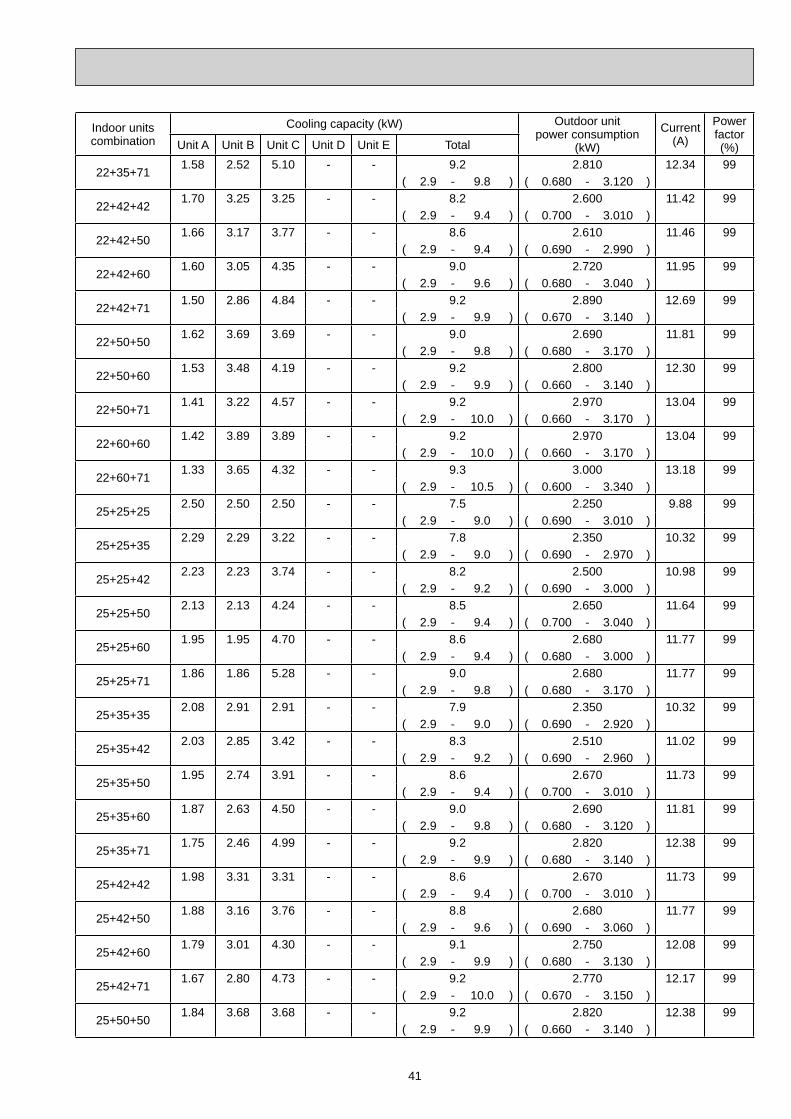
41
Indoor unitscombination
Cooling capacity (kW) Outdoor unitpower consumption
(kW)
Current(A)
Powerfactor(%)Unit A Unit B Unit C Unit D Unit E Total
22+35+711.58 2.52 5.10 - - 9.2 2.810 12.34 99
( 2.9 - 9.8 ) ( 0.680 - 3.120 )
22+42+421.70 3.25 3.25 - - 8.2 2.600 11.42 99
( 2.9 - 9.4 ) ( 0.700 - 3.010 )
22+42+501.66 3.17 3.77 - - 8.6 2.610 11.46 99
( 2.9 - 9.4 ) ( 0.690 - 2.990 )
22+42+601.60 3.05 4.35 - - 9.0 2.720 11.95 99
( 2.9 - 9.6 ) ( 0.680 - 3.040 )
22+42+711.50 2.86 4.84 - - 9.2 2.890 12.69 99
( 2.9 - 9.9 ) ( 0.670 - 3.140 )
22+50+501.62 3.69 3.69 - - 9.0 2.690 11.81 99
( 2.9 - 9.8 ) ( 0.680 - 3.170 )
22+50+601.53 3.48 4.19 - - 9.2 2.800 12.30 99
( 2.9 - 9.9 ) ( 0.660 - 3.140 )
22+50+711.41 3.22 4.57 - - 9.2 2.970 13.04 99
( 2.9 - 10.0 ) ( 0.660 - 3.170 )
22+60+601.42 3.89 3.89 - - 9.2 2.970 13.04 99
( 2.9 - 10.0 ) ( 0.660 - 3.170 )
22+60+711.33 3.65 4.32 - - 9.3 3.000 13.18 99
( 2.9 - 10.5 ) ( 0.600 - 3.340 )
25+25+252.50 2.50 2.50 - - 7.5 2.250 9.88 99
( 2.9 - 9.0 ) ( 0.690 - 3.010 )
25+25+352.29 2.29 3.22 - - 7.8 2.350 10.32 99
( 2.9 - 9.0 ) ( 0.690 - 2.970 )
25+25+422.23 2.23 3.74 - - 8.2 2.500 10.98 99
( 2.9 - 9.2 ) ( 0.690 - 3.000 )
25+25+502.13 2.13 4.24 - - 8.5 2.650 11.64 99
( 2.9 - 9.4 ) ( 0.700 - 3.040 )
25+25+601.95 1.95 4.70 - - 8.6 2.680 11.77 99
( 2.9 - 9.4 ) ( 0.680 - 3.000 )
25+25+711.86 1.86 5.28 - - 9.0 2.680 11.77 99
( 2.9 - 9.8 ) ( 0.680 - 3.170 )
25+35+352.08 2.91 2.91 - - 7.9 2.350 10.32 99
( 2.9 - 9.0 ) ( 0.690 - 2.920 )
25+35+422.03 2.85 3.42 - - 8.3 2.510 11.02 99
( 2.9 - 9.2 ) ( 0.690 - 2.960 )
25+35+501.95 2.74 3.91 - - 8.6 2.670 11.73 99
( 2.9 - 9.4 ) ( 0.700 - 3.010 )
25+35+601.87 2.63 4.50 - - 9.0 2.690 11.81 99
( 2.9 - 9.8 ) ( 0.680 - 3.120 )
25+35+711.75 2.46 4.99 - - 9.2 2.820 12.38 99
( 2.9 - 9.9 ) ( 0.680 - 3.140 )
25+42+421.98 3.31 3.31 - - 8.6 2.670 11.73 99
( 2.9 - 9.4 ) ( 0.700 - 3.010 )
25+42+501.88 3.16 3.76 - - 8.8 2.680 11.77 99
( 2.9 - 9.6 ) ( 0.690 - 3.060 )
25+42+601.79 3.01 4.30 - - 9.1 2.750 12.08 99
( 2.9 - 9.9 ) ( 0.680 - 3.130 )
25+42+711.67 2.80 4.73 - - 9.2 2.770 12.17 99
( 2.9 - 10.0 ) ( 0.670 - 3.150 )
25+50+501.84 3.68 3.68 - - 9.2 2.820 12.38 99
( 2.9 - 9.9 ) ( 0.660 - 3.140 )

42
Indoor unitscombination
Cooling capacity (kW) Outdoor unitpower consumption
(kW)
Current(A)
Powerfactor(%)Unit A Unit B Unit C Unit D Unit E Total
25+50+601.70 3.41 4.09 - - 9.2 2.800 12.30 99
( 2.9 - 9.9 ) ( 0.660 - 3.140 )
25+50+711.58 3.15 4.47 - - 9.2 2.730 11.99 99
( 2.9 - 10.0 ) ( 0.660 - 3.170 )
25+60+601.58 3.81 3.81 - - 9.2 2.730 11.99 99
( 2.9 - 10.0 ) ( 0.660 - 3.170 )
25+60+711.51 3.62 4.27 - - 9.4 2.800 12.30 99
( 2.9 - 10.5 ) ( 0.660 - 3.330 )
35+35+352.87 2.87 2.87 - - 8.6 2.550 11.20 99
( 2.9 - 9.4 ) ( 0.720 - 3.030 )
35+35+422.70 2.70 3.40 - - 8.8 2.620 11.51 99
( 2.9 - 9.6 ) ( 0.710 - 3.070 )
35+35+502.63 2.63 3.74 - - 9.0 2.690 11.81 99
( 2.9 - 9.8 ) ( 0.700 - 3.120 )
35+35+602.48 2.48 4.24 - - 9.2 2.810 12.34 99
( 2.9 - 9.9 ) ( 0.680 - 3.140 )
35+35+712.26 2.26 4.58 - - 9.1 2.740 12.03 99
( 2.9 - 10.0 ) ( 0.680 - 3.170 )
35+42+422.64 3.18 3.18 - - 9.0 2.690 11.81 99
( 2.9 - 9.8 ) ( 0.700 - 3.120 )
35+42+502.51 3.01 3.58 - - 9.1 2.750 12.08 99
( 2.9 - 9.9 ) ( 0.690 - 3.130 )
35+42+602.35 2.82 4.03 - - 9.2 2.770 12.17 99
( 2.9 - 10.0 ) ( 0.680 - 3.150 )
35+42+712.20 2.64 4.46 - - 9.3 2.760 12.12 99
( 2.9 - 10.3 ) ( 0.670 - 3.250 )
35+50+502.34 3.33 3.33 - - 9.0 2.720 11.95 99
( 2.9 - 9.9 ) ( 0.680 - 3.140 )
35+50+602.22 3.17 3.81 - - 9.2 2.730 11.99 99
( 2.9 - 10.0 ) ( 0.660 - 3.170 )
35+50+712.11 3.01 4.28 - - 9.4 2.790 12.25 99
( 2.9 - 10.5 ) ( 0.660 - 3.330 )
35+60+602.12 3.64 3.64 - - 9.4 2.790 12.25 99
( 2.9 - 10.5 ) ( 0.660 - 3.330 )
35+60+712.00 3.43 4.07 - - 9.5 2.780 12.21 99
( 2.9 - 10.8 ) ( 0.660 - 3.430 )
42+42+423.00 3.00 3.00 - - 9.0 2.750 12.08 99
( 2.9 - 9.9 ) ( 0.690 - 3.130 )
42+42+502.88 2.88 3.44 - - 9.2 2.760 12.12 99
( 2.9 - 10.0 ) ( 0.680 - 3.140 )
42+42+602.71 2.71 3.88 - - 9.3 2.760 12.12 99
( 2.9 - 10.2 ) ( 0.670 - 3.200 )
42+42+712.54 2.54 4.32 - - 9.4 2.790 12.25 99
( 2.9 - 10.5 ) ( 0.660 - 3.330 )
42+50+502.76 3.27 3.27 - - 9.3 2.760 12.12 99
( 2.9 - 10.2 ) ( 0.670 - 3.200 )
42+50+602.60 3.09 3.71 - - 9.4 2.760 12.12 99
( 2.9 - 10.5 ) ( 0.660 - 3.310 )
42+50+712.45 2.91 4.14 - - 9.5 2.810 12.34 99
( 2.9 - 10.8 ) ( 0.660 - 3.400 )
42+60+602.46 3.52 3.52 - - 9.5 2.810 12.34 99
( 2.9 - 10.8 ) ( 0.660 - 3.400 )

43
Indoor unitscombination
Cooling capacity (kW) Outdoor unitpower consumption
(kW)
Current(A)
Powerfactor(%)Unit A Unit B Unit C Unit D Unit E Total
50+50+503.13 3.13 3.13 - - 9.4 2.790 12.25 99
( 2.9 - 10.8 ) ( 0.660 - 3.430 )
50+50+602.97 2.97 3.56 - - 9.5 2.790 12.25 99
( 2.9 - 10.9 ) ( 0.660 - 3.450 )
50+50+712.81 2.81 3.98 - - 9.6 2.830 12.43 99
( 2.9 - 11.0 ) ( 0.660 - 3.480 )
22+22+22+221.95 1.95 1.95 1.95 - 7.8 2.180 9.57 99
( 3.7 - 9.2 ) ( 0.810 - 2.670 )
22+22+22+251.91 1.91 1.91 2.17 - 7.9 2.190 9.62 99
( 3.7 - 9.2 ) ( 0.810 - 2.670 )
22+22+22+351.76 1.76 1.76 2.82 - 8.1 2.280 10.01 99
( 3.7 - 9.4 ) ( 0.810 - 2.730 )
22+22+22+421.71 1.71 1.71 3.27 - 8.4 2.340 10.28 99
( 3.7 - 9.7 ) ( 0.800 - 2.830 )
22+22+22+501.63 1.63 1.63 3.71 - 8.6 2.410 10.58 99
( 3.7 - 9.9 ) ( 0.790 - 2.930 )
22+22+22+601.57 1.57 1.57 4.29 - 9.0 2.510 11.02 99
( 3.7 - 10.1 ) ( 0.770 - 3.000 )
22+22+22+711.48 1.48 1.48 4.76 - 9.2 2.570 11.29 99
( 3.7 - 10.1 ) ( 0.770 - 2.980 )
22+22+25+251.87 1.87 2.13 2.13 - 8.0 2.260 9.93 99
( 3.7 - 9.4 ) ( 0.810 - 2.750 )
22+22+25+351.82 1.82 2.07 2.89 - 8.6 2.480 10.89 99
( 3.7 - 9.9 ) ( 0.810 - 2.970 )
22+22+25+421.74 1.74 1.98 3.34 - 8.8 2.470 10.85 99
( 3.7 - 10.1 ) ( 0.800 - 2.990 )
22+22+25+501.65 1.65 1.87 3.73 - 8.9 2.460 10.80 99
( 3.7 - 10.2 ) ( 0.790 - 3.020 )
22+22+25+601.53 1.53 1.74 4.20 - 9.0 2.510 11.02 99
( 3.7 - 10.1 ) ( 0.770 - 2.950 )
22+22+25+711.41 1.41 1.61 4.57 - 9.0 2.490 10.94 99
( 3.7 - 10.0 ) ( 0.770 - 2.920 )
22+22+35+351.66 1.66 2.64 2.64 - 8.6 2.480 10.89 99
( 3.7 - 9.9 ) ( 0.810 - 2.930 )
22+22+35+421.62 1.62 2.57 3.09 - 8.9 2.490 10.94 99
( 3.7 - 10.1 ) ( 0.800 - 2.940 )
22+22+35+501.53 1.53 2.44 3.50 - 9.0 2.510 11.02 99
( 3.7 - 10.1 ) ( 0.790 - 2.950 )
22+22+35+601.42 1.42 2.27 3.89 - 9.0 2.490 10.94 99
( 3.7 - 10.0 ) ( 0.770 - 2.920 )
22+22+35+711.38 1.38 2.19 4.45 - 9.4 2.580 11.33 99
( 3.7 - 10.5 ) ( 0.770 - 3.060 )
22+22+42+421.55 1.55 2.95 2.95 - 9.0 2.510 11.02 99
( 3.7 - 10.1 ) ( 0.790 - 2.950 )
22+22+42+501.45 1.45 2.78 3.32 - 9.0 2.500 10.98 99
( 3.7 - 10.1 ) ( 0.780 - 2.930 )
22+22+42+601.38 1.38 2.65 3.79 - 9.2 2.530 11.11 99
( 3.7 - 10.3 ) ( 0.770 - 2.990 )
22+22+42+711.33 1.33 2.54 4.30 - 9.5 2.560 11.24 99
( 3.7 - 10.5 ) ( 0.770 - 3.040 )
22+22+50+501.48 1.48 3.37 3.37 - 9.7 2.740 12.03 99
( 3.7 - 10.9 ) ( 0.770 - 3.250 )

44
Indoor unitscombination
Cooling capacity (kW) Outdoor unitpower consumption
(kW)
Current(A)
Powerfactor(%)Unit A Unit B Unit C Unit D Unit E Total
22+22+50+601.34 1.34 3.05 3.67 - 9.4 2.580 11.33 99
( 3.7 - 10.5 ) ( 0.770 - 3.060 )
22+22+50+711.28 1.28 2.91 4.13 - 9.6 2.550 11.20 99
( 3.7 - 10.5 ) ( 0.770 - 3.030 )
22+25+25+251.83 2.09 2.09 2.09 - 8.1 2.200 9.66 99
( 3.7 - 9.4 ) ( 0.810 - 2.750 )
22+25+25+351.77 2.01 2.01 2.81 - 8.6 2.480 10.89 99
( 3.7 - 9.9 ) ( 0.810 - 2.970 )
22+25+25+421.67 1.91 1.91 3.21 - 8.7 2.450 10.76 99
( 3.7 - 10.1 ) ( 0.800 - 2.960 )
22+25+25+501.59 1.80 1.80 3.61 - 8.8 2.430 10.67 99
( 3.7 - 10.1 ) ( 0.790 - 2.950 )
22+25+25+601.50 1.70 1.70 4.10 - 9.0 2.510 11.02 99
( 3.7 - 10.2 ) ( 0.770 - 3.000 )
22+25+25+711.45 1.64 1.64 4.67 - 9.4 2.580 11.33 99
( 3.7 - 10.5 ) ( 0.770 - 3.060 )
22+25+35+351.67 1.90 2.66 2.66 - 8.9 2.460 10.80 99
( 3.7 - 10.2 ) ( 0.810 - 3.020 )
22+25+35+421.60 1.81 2.54 3.05 - 9.0 2.480 10.89 99
( 3.7 - 10.2 ) ( 0.810 - 3.010 )
22+25+35+501.50 1.70 2.39 3.41 - 9.0 2.510 11.02 99
( 3.7 - 10.2 ) ( 0.810 - 3.000 )
22+25+35+601.46 1.65 2.32 3.97 - 9.4 2.600 11.42 99
( 3.7 - 10.5 ) ( 0.770 - 3.060 )
22+25+35+711.35 1.54 2.15 4.36 - 9.4 2.580 11.33 99
( 3.7 - 10.6 ) ( 0.770 - 3.100 )
22+25+42+421.51 1.71 2.89 2.89 - 9.0 2.510 11.02 99
( 3.7 - 10.2 ) ( 0.810 - 3.000 )
22+25+42+501.46 1.65 2.78 3.31 - 9.2 2.550 11.20 99
( 3.7 - 10.4 ) ( 0.790 - 3.030 )
22+25+42+601.39 1.57 2.65 3.79 - 9.4 2.590 11.37 99
( 3.7 - 10.6 ) ( 0.770 - 3.080 )
22+25+42+711.31 1.48 2.49 4.22 - 9.5 2.550 11.20 99
( 3.7 - 10.8 ) ( 0.770 - 3.130 )
22+25+50+501.40 1.60 3.20 3.20 - 9.4 2.600 11.42 99
( 3.7 - 10.5 ) ( 0.770 - 3.060 )
22+25+50+601.32 1.50 2.99 3.59 - 9.4 2.580 11.33 99
( 3.7 - 11.0 ) ( 0.770 - 3.210 )
22+25+50+711.25 1.43 2.86 4.06 - 9.6 2.530 11.11 99
( 3.7 - 11.0 ) ( 0.770 - 3.170 )
22+35+35+351.58 2.54 2.54 2.54 - 9.2 2.580 11.33 99
( 3.7 - 10.3 ) ( 0.810 - 3.040 )
22+35+35+421.53 2.43 2.43 2.91 - 9.3 2.590 11.37 99
( 3.7 - 10.2 ) ( 0.800 - 2.980 )
22+35+35+501.45 2.32 2.32 3.31 - 9.4 2.600 11.42 99
( 3.7 - 10.0 ) ( 0.790 - 2.920 )
22+35+35+601.36 2.16 2.16 3.72 - 9.4 2.580 11.33 99
( 3.7 - 10.5 ) ( 0.770 - 3.060 )
22+35+35+711.30 2.06 2.06 4.18 - 9.6 2.560 11.24 99
( 3.7 - 10.9 ) ( 0.770 - 3.170 )
22+35+42+421.47 2.33 2.80 2.80 - 9.4 2.600 11.42 99
( 3.7 - 10.0 ) ( 0.790 - 2.920 )

45
Indoor unitscombination
Cooling capacity (kW) Outdoor unitpower consumption
(kW)
Current(A)
Powerfactor(%)Unit A Unit B Unit C Unit D Unit E Total
22+35+42+501.39 2.21 2.65 3.15 - 9.4 2.600 11.42 99
( 3.7 - 10.3 ) ( 0.800 - 3.000 )
22+35+42+601.32 2.09 2.51 3.58 - 9.5 2.600 11.42 99
( 3.7 - 10.7 ) ( 0.800 - 3.200 )
22+35+42+711.24 1.98 2.37 4.01 - 9.6 2.530 11.11 99
( 3.7 - 11.0 ) ( 0.770 - 3.170 )
22+35+50+501.34 2.14 3.06 3.06 - 9.6 2.540 11.16 99
( 3.7 - 10.9 ) ( 0.770 - 3.170 )
22+35+50+601.26 2.01 2.87 3.44 - 9.6 2.530 11.11 99
( 3.7 - 11.0 ) ( 0.770 - 3.170 )
22+42+42+421.39 2.67 2.67 2.67 - 9.4 2.600 11.42 99
( 3.7 - 10.3 ) ( 0.800 - 3.000 )
22+42+42+501.34 2.56 2.56 3.04 - 9.5 2.600 11.42 99
( 3.7 - 10.7 ) ( 0.800 - 3.200 )
22+42+42+601.27 2.43 2.43 3.47 - 9.6 2.530 11.11 99
( 3.7 - 11.0 ) ( 0.770 - 3.170 )
22+42+50+501.29 2.45 2.93 2.93 - 9.6 2.530 11.11 99
( 3.7 - 11.0 ) ( 0.770 - 3.170 )
25+25+25+252.15 2.15 2.15 2.15 - 8.6 2.410 10.58 99
( 3.7 - 9.9 ) ( 0.810 - 2.990 )
25+25+25+351.95 1.95 1.95 2.75 - 8.6 2.490 10.94 99
( 3.7 - 9.9 ) ( 0.810 - 2.970 )
25+25+25+421.90 1.90 1.90 3.20 - 8.9 2.500 10.98 99
( 3.7 - 10.1 ) ( 0.800 - 2.960 )
25+25+25+501.80 1.80 1.80 3.60 - 9.0 2.510 11.02 99
( 3.7 - 10.1 ) ( 0.790 - 2.950 )
25+25+25+601.69 1.69 1.69 4.03 - 9.1 2.530 11.11 99
( 3.7 - 10.2 ) ( 0.770 - 3.000 )
25+25+25+711.61 1.61 1.61 4.57 - 9.4 2.580 11.33 99
( 3.7 - 10.5 ) ( 0.770 - 3.060 )
25+25+35+351.83 1.83 2.57 2.57 - 8.8 2.430 10.67 99
( 3.7 - 10.1 ) ( 0.810 - 2.950 )
25+25+35+421.79 1.79 2.51 3.01 - 9.1 2.530 11.11 99
( 3.7 - 10.2 ) ( 0.800 - 2.970 )
25+25+35+501.70 1.70 2.39 3.41 - 9.2 2.640 11.59 99
( 3.7 - 10.2 ) ( 0.790 - 3.000 )
25+25+35+601.62 1.62 2.27 3.89 - 9.4 2.600 11.42 99
( 3.7 - 10.5 ) ( 0.770 - 3.060 )
25+25+35+711.54 1.54 2.15 4.37 - 9.6 2.650 11.64 99
( 3.7 - 11.0 ) ( 0.770 - 3.210 )
25+25+42+421.72 1.72 2.88 2.88 - 9.2 2.640 11.59 99
( 3.7 - 10.2 ) ( 0.790 - 3.000 )
25+25+42+501.64 1.64 2.75 3.27 - 9.3 2.600 11.42 99
( 3.7 - 10.4 ) ( 0.800 - 3.100 )
25+25+42+601.56 1.56 2.63 3.75 - 9.5 2.700 11.86 99
( 3.7 - 10.8 ) ( 0.800 - 3.200 )
25+25+42+711.47 1.47 2.46 4.20 - 9.6 2.560 11.24 99
( 3.7 - 11.0 ) ( 0.770 - 3.170 )
25+25+50+501.57 1.57 3.13 3.13 - 9.4 2.550 11.20 99
( 3.7 - 10.5 ) ( 0.770 - 3.060 )
25+25+50+601.50 1.50 3.00 3.60 - 9.6 2.560 11.24 99
( 3.7 - 11.0 ) ( 0.770 - 3.170 )

46
Indoor unitscombination
Cooling capacity (kW) Outdoor unitpower consumption
(kW)
Current(A)
Powerfactor(%)Unit A Unit B Unit C Unit D Unit E Total
25+25+50+711.43 1.43 2.87 4.07 - 9.8 2.610 11.46 99
( 3.7 - 11.0 ) ( 0.770 - 3.170 )
25+35+35+351.74 2.42 2.42 2.42 - 9.0 2.510 11.02 99
( 3.7 - 10.2 ) ( 0.810 - 2.840 )
25+35+35+421.68 2.35 2.35 2.82 - 9.2 2.540 11.16 99
( 3.7 - 10.4 ) ( 0.800 - 2.950 )
25+35+35+501.62 2.27 2.27 3.24 - 9.4 2.580 11.33 99
( 3.7 10.5 ) ( 0.790 3.060 )
25+35+35+601.55 2.17 2.17 3.71 - 9.6 2.650 11.64 99
( 3.7 10.5 ) ( 0.790 3.060 )
25+35+35+711.45 2.02 2.02 4.11 - 9.6 2.560 11.24 99
( 3.7 10.9 ) ( 0.770 3.170 )
25+35+42+421.63 2.29 2.74 2.74 - 9.4 2.580 11.33 99
( 3.7 - 10.5 ) ( 0.790 - 3.060 )
25+35+42+501.56 2.19 2.62 3.13 - 9.5 2.700 11.86 99
( 3.7 - 10.5 ) ( 0.800 - 3.100 )
25+35+42+601.48 2.07 2.49 3.56 - 9.6 2.700 11.86 99
( 3.7 - 10.7 ) ( 0.800 - 3.200 )
25+42+42+421.58 2.64 2.64 2.64 - 9.5 2.700 11.86 99
( 3.7 - 10.5 ) ( 0.800 - 3.100 )
25+42+42+501.50 2.54 2.54 3.02 - 9.6 2.700 11.86 99
( 3.7 - 10.7 ) ( 0.800 - 3.200 )
25+42+42+601.46 2.43 2.43 3.48 - 9.8 2.610 11.46 99
( 3.7 - 11.0 ) ( 0.770 - 3.170 )
25+42+50+501.48 2.46 2.93 2.93 - 9.8 2.610 11.46 99
( 3.7 - 11.0 ) ( 0.770 - 3.170 )
35+35+35+352.35 2.35 2.35 2.35 - 9.4 2.570 11.29 99
( 3.7 - 10.5 ) ( 0.810 - 3.100 )
35+35+35+422.26 2.26 2.26 2.72 - 9.5 2.600 11.42 99
( 3.7 - 10.8 ) ( 0.790 - 3.150 )
35+35+35+502.17 2.17 2.17 3.09 - 9.6 2.640 11.59 99
( 3.7 - 11.0 ) ( 0.770 - 3.210 )
35+35+35+602.04 2.04 2.04 3.48 - 9.6 2.560 11.24 99
( 3.7 - 10.9 ) ( 0.770 - 3.170 )
35+35+42+422.16 2.16 2.64 2.64 - 9.6 2.640 11.59 99
( 3.7 - 11.0 ) ( 0.770 - 3.210 )
35+35+42+502.07 2.07 2.49 2.97 - 9.6 2.600 11.42 99
( 3.7 - 11.0 ) ( 0.800 - 3.200 )
35+42+42+422.10 2.50 2.50 2.50 - 9.6 2.600 11.42 99
( 3.7 - 11.0 ) ( 0.800 - 3.200 )
35+42+42+502.03 2.43 2.43 2.91 - 9.8 2.610 11.46 99
( 3.7 - 11.0 ) ( 0.770 - 3.170 )
42+42+42+422.45 2.45 2.45 2.45 - 9.8 2.610 11.46 99
( 3.7 - 11.0 ) ( 0.770 - 3.170 )
22+22+22+22+222.00 2.00 2.00 2.00 2.00 10.0 2.935 12.89 99
( 3.9 - 11.0 ) ( 0.780 - 3.500 )
22+22+22+22+251.95 1.95 1.95 1.95 2.20 10.0 2.935 12.89 99
( 3.9 - 11.0 ) ( 0.780 - 3.500 )
22+22+22+22+351.79 1.79 1.79 1.79 2.84 10.0 2.935 12.89 99
( 3.9 - 11.0 ) ( 0.780 - 3.500 )
22+22+22+22+421.69 1.69 1.69 1.69 3.24 10.0 2.920 12.82 99
( 3.9 - 11.0 ) ( 0.780 - 3.490 )
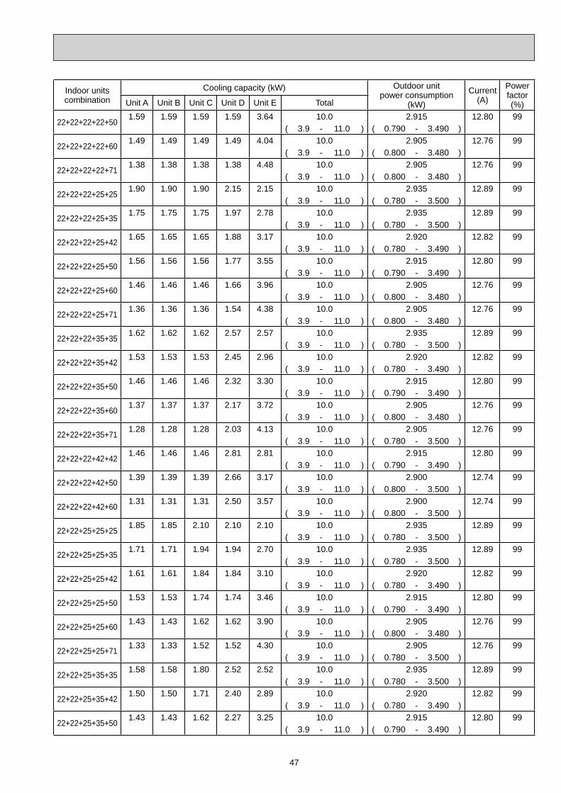
47
Indoor unitscombination
Cooling capacity (kW) Outdoor unitpower consumption
(kW)
Current(A)
Powerfactor(%)Unit A Unit B Unit C Unit D Unit E Total
22+22+22+22+501.59 1.59 1.59 1.59 3.64 10.0 2.915 12.80 99
( 3.9 - 11.0 ) ( 0.790 - 3.490 )
22+22+22+22+601.49 1.49 1.49 1.49 4.04 10.0 2.905 12.76 99
( 3.9 - 11.0 ) ( 0.800 - 3.480 )
22+22+22+22+711.38 1.38 1.38 1.38 4.48 10.0 2.905 12.76 99
( 3.9 - 11.0 ) ( 0.800 - 3.480 )
22+22+22+25+251.90 1.90 1.90 2.15 2.15 10.0 2.935 12.89 99
( 3.9 - 11.0 ) ( 0.780 - 3.500 )
22+22+22+25+351.75 1.75 1.75 1.97 2.78 10.0 2.935 12.89 99
( 3.9 - 11.0 ) ( 0.780 - 3.500 )
22+22+22+25+421.65 1.65 1.65 1.88 3.17 10.0 2.920 12.82 99
( 3.9 - 11.0 ) ( 0.780 - 3.490 )
22+22+22+25+501.56 1.56 1.56 1.77 3.55 10.0 2.915 12.80 99
( 3.9 - 11.0 ) ( 0.790 - 3.490 )
22+22+22+25+601.46 1.46 1.46 1.66 3.96 10.0 2.905 12.76 99
( 3.9 - 11.0 ) ( 0.800 - 3.480 )
22+22+22+25+711.36 1.36 1.36 1.54 4.38 10.0 2.905 12.76 99
( 3.9 - 11.0 ) ( 0.800 - 3.480 )
22+22+22+35+351.62 1.62 1.62 2.57 2.57 10.0 2.935 12.89 99
( 3.9 - 11.0 ) ( 0.780 - 3.500 )
22+22+22+35+421.53 1.53 1.53 2.45 2.96 10.0 2.920 12.82 99
( 3.9 - 11.0 ) ( 0.780 - 3.490 )
22+22+22+35+501.46 1.46 1.46 2.32 3.30 10.0 2.915 12.80 99
( 3.9 - 11.0 ) ( 0.790 - 3.490 )
22+22+22+35+601.37 1.37 1.37 2.17 3.72 10.0 2.905 12.76 99
( 3.9 - 11.0 ) ( 0.800 - 3.480 )
22+22+22+35+711.28 1.28 1.28 2.03 4.13 10.0 2.905 12.76 99
( 3.9 - 11.0 ) ( 0.780 - 3.500 )
22+22+22+42+421.46 1.46 1.46 2.81 2.81 10.0 2.915 12.80 99
( 3.9 - 11.0 ) ( 0.790 - 3.490 )
22+22+22+42+501.39 1.39 1.39 2.66 3.17 10.0 2.900 12.74 99
( 3.9 - 11.0 ) ( 0.800 - 3.500 )
22+22+22+42+601.31 1.31 1.31 2.50 3.57 10.0 2.900 12.74 99
( 3.9 - 11.0 ) ( 0.800 - 3.500 )
22+22+25+25+251.85 1.85 2.10 2.10 2.10 10.0 2.935 12.89 99
( 3.9 - 11.0 ) ( 0.780 - 3.500 )
22+22+25+25+351.71 1.71 1.94 1.94 2.70 10.0 2.935 12.89 99
( 3.9 - 11.0 ) ( 0.780 - 3.500 )
22+22+25+25+421.61 1.61 1.84 1.84 3.10 10.0 2.920 12.82 99
( 3.9 - 11.0 ) ( 0.780 - 3.490 )
22+22+25+25+501.53 1.53 1.74 1.74 3.46 10.0 2.915 12.80 99
( 3.9 - 11.0 ) ( 0.790 - 3.490 )
22+22+25+25+601.43 1.43 1.62 1.62 3.90 10.0 2.905 12.76 99
( 3.9 - 11.0 ) ( 0.800 - 3.480 )
22+22+25+25+711.33 1.33 1.52 1.52 4.30 10.0 2.905 12.76 99
( 3.9 - 11.0 ) ( 0.780 - 3.500 )
22+22+25+35+351.58 1.58 1.80 2.52 2.52 10.0 2.935 12.89 99
( 3.9 - 11.0 ) ( 0.780 - 3.500 )
22+22+25+35+421.50 1.50 1.71 2.40 2.89 10.0 2.920 12.82 99
( 3.9 - 11.0 ) ( 0.780 - 3.490 )
22+22+25+35+501.43 1.43 1.62 2.27 3.25 10.0 2.915 12.80 99
( 3.9 - 11.0 ) ( 0.790 - 3.490 )
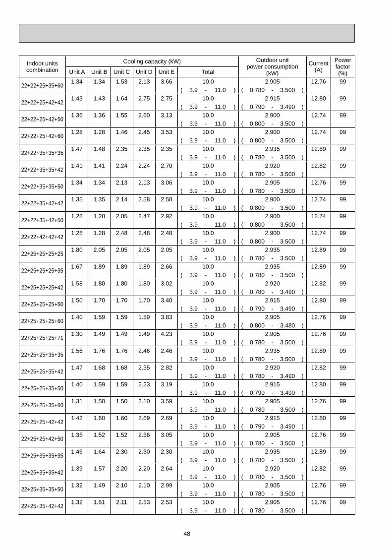
48
Indoor unitscombination
Cooling capacity (kW) Outdoor unitpower consumption
(kW)
Current(A)
Powerfactor(%)Unit A Unit B Unit C Unit D Unit E Total
22+22+25+35+601.34 1.34 1.53 2.13 3.66 10.0 2.905 12.76 99
( 3.9 - 11.0 ) ( 0.780 - 3.500 )
22+22+25+42+421.43 1.43 1.64 2.75 2.75 10.0 2.915 12.80 99
( 3.9 - 11.0 ) ( 0.790 - 3.490 )
22+22+25+42+501.36 1.36 1.55 2.60 3.13 10.0 2.900 12.74 99
( 3.9 - 11.0 ) ( 0.800 - 3.500 )
22+22+25+42+601.28 1.28 1.46 2.45 3.53 10.0 2.900 12.74 99
( 3.9 - 11.0 ) ( 0.800 - 3.500 )
22+22+35+35+351.47 1.48 2.35 2.35 2.35 10.0 2.935 12.89 99
( 3.9 - 11.0 ) ( 0.780 - 3.500 )
22+22+35+35+421.41 1.41 2.24 2.24 2.70 10.0 2.920 12.82 99
( 3.9 - 11.0 ) ( 0.780 - 3.500 )
22+22+35+35+501.34 1.34 2.13 2.13 3.06 10.0 2.905 12.76 99
( 3.9 - 11.0 ) ( 0.780 - 3.500 )
22+22+35+42+421.35 1.35 2.14 2.58 2.58 10.0 2.900 12.74 99
( 3.9 - 11.0 ) ( 0.800 - 3.500 )
22+22+35+42+501.28 1.28 2.05 2.47 2.92 10.0 2.900 12.74 99
( 3.9 - 11.0 ) ( 0.800 - 3.500 )
22+22+42+42+421.28 1.28 2.48 2.48 2.48 10.0 2.900 12.74 99
( 3.9 - 11.0 ) ( 0.800 - 3.500 )
22+25+25+25+251.80 2.05 2.05 2.05 2.05 10.0 2.935 12.89 99
( 3.9 - 11.0 ) ( 0.780 - 3.500 )
22+25+25+25+351.67 1.89 1.89 1.89 2.66 10.0 2.935 12.89 99
( 3.9 - 11.0 ) ( 0.780 - 3.500 )
22+25+25+25+421.58 1.80 1.80 1.80 3.02 10.0 2.920 12.82 99
( 3.9 - 11.0 ) ( 0.780 - 3.490 )
22+25+25+25+501.50 1.70 1.70 1.70 3.40 10.0 2.915 12.80 99
( 3.9 - 11.0 ) ( 0.790 - 3.490 )
22+25+25+25+601.40 1.59 1.59 1.59 3.83 10.0 2.905 12.76 99
( 3.9 - 11.0 ) ( 0.800 - 3.480 )
22+25+25+25+711.30 1.49 1.49 1.49 4.23 10.0 2.905 12.76 99
( 3.9 - 11.0 ) ( 0.780 - 3.500 )
22+25+25+35+351.56 1.76 1.76 2.46 2.46 10.0 2.935 12.89 99
( 3.9 - 11.0 ) ( 0.780 - 3.500 )
22+25+25+35+421.47 1.68 1.68 2.35 2.82 10.0 2.920 12.82 99
( 3.9 - 11.0 ) ( 0.780 - 3.490 )
22+25+25+35+501.40 1.59 1.59 2.23 3.19 10.0 2.915 12.80 99
( 3.9 - 11.0 ) ( 0.790 - 3.490 )
22+25+25+35+601.31 1.50 1.50 2.10 3.59 10.0 2.905 12.76 99
( 3.9 - 11.0 ) ( 0.780 - 3.500 )
22+25+25+42+421.42 1.60 1.60 2.69 2.69 10.0 2.915 12.80 99
( 3.9 - 11.0 ) ( 0.790 - 3.490 )
22+25+25+42+501.35 1.52 1.52 2.56 3.05 10.0 2.905 12.76 99
( 3.9 - 11.0 ) ( 0.780 - 3.500 )
22+25+35+35+351.46 1.64 2.30 2.30 2.30 10.0 2.935 12.89 99
( 3.9 - 11.0 ) ( 0.780 - 3.500 )
22+25+35+35+421.39 1.57 2.20 2.20 2.64 10.0 2.920 12.82 99
( 3.9 - 11.0 ) ( 0.780 - 3.500 )
22+25+35+35+501.32 1.49 2.10 2.10 2.99 10.0 2.905 12.76 99
( 3.9 - 11.0 ) ( 0.780 - 3.500 )
22+25+35+42+421.32 1.51 2.11 2.53 2.53 10.0 2.905 12.76 99
( 3.9 - 11.0 ) ( 0.780 - 3.500 )
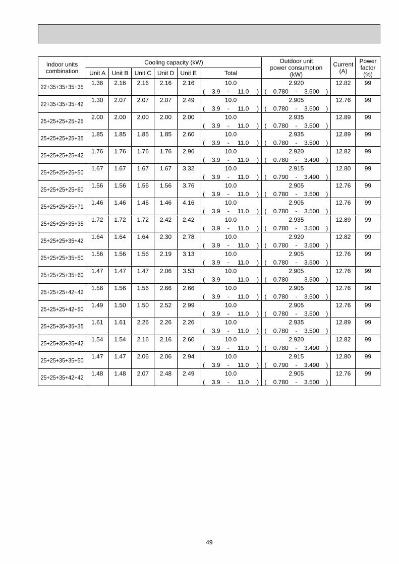
49
Indoor unitscombination
Cooling capacity (kW) Outdoor unitpower consumption
(kW)
Current(A)
Powerfactor(%)Unit A Unit B Unit C Unit D Unit E Total
22+35+35+35+351.36 2.16 2.16 2.16 2.16 10.0 2.920 12.82 99
( 3.9 - 11.0 ) ( 0.780 - 3.500 )
22+35+35+35+421.30 2.07 2.07 2.07 2.49 10.0 2.905 12.76 99
( 3.9 - 11.0 ) ( 0.780 - 3.500 )
25+25+25+25+252.00 2.00 2.00 2.00 2.00 10.0 2.935 12.89 99
( 3.9 - 11.0 ) ( 0.780 - 3.500 )
25+25+25+25+351.85 1.85 1.85 1.85 2.60 10.0 2.935 12.89 99
( 3.9 - 11.0 ) ( 0.780 - 3.500 )
25+25+25+25+421.76 1.76 1.76 1.76 2.96 10.0 2.920 12.82 99
( 3.9 - 11.0 ) ( 0.780 - 3.490 )
25+25+25+25+501.67 1.67 1.67 1.67 3.32 10.0 2.915 12.80 99
( 3.9 - 11.0 ) ( 0.790 - 3.490 )
25+25+25+25+601.56 1.56 1.56 1.56 3.76 10.0 2.905 12.76 99
( 3.9 - 11.0 ) ( 0.780 - 3.500 )
25+25+25+25+711.46 1.46 1.46 1.46 4.16 10.0 2.905 12.76 99
( 3.9 - 11.0 ) ( 0.780 - 3.500 )
25+25+25+35+351.72 1.72 1.72 2.42 2.42 10.0 2.935 12.89 99
( 3.9 - 11.0 ) ( 0.780 - 3.500 )
25+25+25+35+421.64 1.64 1.64 2.30 2.78 10.0 2.920 12.82 99
( 3.9 - 11.0 ) ( 0.780 - 3.500 )
25+25+25+35+501.56 1.56 1.56 2.19 3.13 10.0 2.905 12.76 99
( 3.9 - 11.0 ) ( 0.780 - 3.500 )
25+25+25+35+601.47 1.47 1.47 2.06 3.53 10.0 2.905 12.76 99
( 3.9 - 11.0 ) ( 0.780 - 3.500 )
25+25+25+42+421.56 1.56 1.56 2.66 2.66 10.0 2.905 12.76 99
( 3.9 - 11.0 ) ( 0.780 - 3.500 )
25+25+25+42+501.49 1.50 1.50 2.52 2.99 10.0 2.905 12.76 99
( 3.9 - 11.0 ) ( 0.780 - 3.500 )
25+25+35+35+351.61 1.61 2.26 2.26 2.26 10.0 2.935 12.89 99
( 3.9 - 11.0 ) ( 0.780 - 3.500 )
25+25+35+35+421.54 1.54 2.16 2.16 2.60 10.0 2.920 12.82 99
( 3.9 - 11.0 ) ( 0.780 - 3.490 )
25+25+35+35+501.47 1.47 2.06 2.06 2.94 10.0 2.915 12.80 99
( 3.9 - 11.0 ) ( 0.790 - 3.490 )
25+25+35+42+421.48 1.48 2.07 2.48 2.49 10.0 2.905 12.76 99
( 3.9 - 11.0 ) ( 0.780 - 3.500 )

50
Indoor unitscombination
Heating capacity (kW) Outdoor unitpower consumption
(kW)
Current(A)
Powerfactor(%)Unit A Unit B Unit C Unit D Unit E Total
223.30 - - - - 3.3 1.050 4.61 99
( 1.2 - 4.6 ) ( 0.340 - 1.590 )
253.60 - - - - 3.6 1.110 4.87 99
( 1.2 - 5.0 ) ( 0.340 - 1.740 )
354.00 - - - - 4.0 1.210 5.31 99
( 1.2 - 5.3 ) ( 0.330 - 1.810 )
425.40 - - - - 5.4 1.740 7.64 99
( 1.3 - 6.8 ) ( 0.330 - 2.260 )
507.20 - - - - 7.2 2.270 9.97 99
( 1.4 - 8.2 ) ( 0.330 - 2.710 )
607.90 - - - - 7.9 2.700 11.86 99
( 1.4 - 8.6 ) ( 0.330 - 3.060 )
718.60 - - - - 8.6 3.220 14.14 99
( 1.6 - 9.2 ) ( 0.360 - 3.520 )
22+223.30 3.30 - - - 6.6 2.020 8.87 99
( 1.8 - 7.2 ) ( 0.480 - 2.760 )
22+253.23 3.67 - - - 6.9 2.120 9.31 99
( 1.8 - 8.7 ) ( 0.480 - 3.000 )
22+352.82 4.48 - - - 7.3 2.130 9.35 99
( 1.8 - 9.2 ) ( 0.480 - 3.110 )
22+422.78 5.32 - - - 8.1 2.300 10.10 99
( 1.8 9.9 ) ( 0.470 - 3.230 )
22+502.72 6.18 - - - 8.9 2.470 10.85 99
( 1.8 - 10.5 ) ( 0.460 - 3.360 )
22+602.68 7.32 - - - 10.0 2.900 12.74 99
( 1.8 - 10.5 ) ( 0.460 - 3.360 )
22+712.37 7.63 - - - 10.0 2.900 12.74 99
( 1.8 - 10.5 ) ( 0.460 - 3.360 )
25+253.60 3.60 - - - 7.2 2.170 9.53 99
( 1.8 - 9.1 ) ( 0.480 - 3.140 )
25+353.17 4.43 - - - 7.6 2.210 9.71 99
( 1.8 - 9.5 ) ( 0.480 - 3.230 )
25+423.10 5.20 - - - 8.3 2.360 10.36 99
( 1.8 - 9.8 ) ( 0.470 - 3.240 )
25+503.00 6.00 - - - 9.0 2.520 11.07 99
( 1.8 - 10.1 ) ( 0.460 - 3.260 )
25+603.09 7.41 - - - 10.5 3.390 14.89 99
( 1.8 - 11.2 ) ( 0.460 - 3.660 )
25+712.73 7.77 - - - 10.5 3.390 14.89 99
( 1.8 - 11.3 ) ( 0.460 - 3.690 )
35+354.00 4.00 - - - 8.0 2.370 10.41 99
( 1.8 - 9.8 ) ( 0.480 - 3.230 )
35+424.23 5.07 - - - 9.3 2.770 12.17 99
( 1.8 - 10.5 ) ( 0.470 - 3.400 )
35+504.32 6.18 - - - 10.5 3.180 13.97 99
( 1.8 - 11.0 ) ( 0.460 - 3.580 )
35+603.87 6.63 - - - 10.5 3.180 13.97 99
( 1.8 - 11.1 ) ( 0.460 - 3.610 )
35+713.50 7.10 - - - 10.6 3.210 14.10 99
( 1.8 - 11.4 ) ( 0.460 - 3.690 )
42+425.25 5.25 - - - 10.5 3.180 13.97 99
( 1.8 - 11.0 ) ( 0.460 - 3.580 )
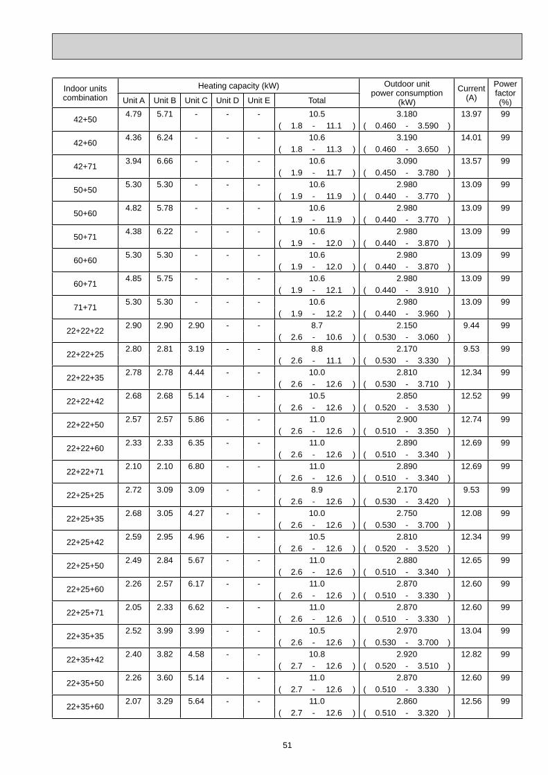
51
Indoor unitscombination
Heating capacity (kW) Outdoor unitpower consumption
(kW)
Current(A)
Powerfactor(%)Unit A Unit B Unit C Unit D Unit E Total
42+504.79 5.71 - - - 10.5 3.180 13.97 99
( 1.8 - 11.1 ) ( 0.460 - 3.590 )
42+604.36 6.24 - - - 10.6 3.190 14.01 99
( 1.8 - 11.3 ) ( 0.460 - 3.650 )
42+713.94 6.66 - - - 10.6 3.090 13.57 99
( 1.9 - 11.7 ) ( 0.450 - 3.780 )
50+505.30 5.30 - - - 10.6 2.980 13.09 99
( 1.9 - 11.9 ) ( 0.440 - 3.770 )
50+604.82 5.78 - - - 10.6 2.980 13.09 99
( 1.9 - 11.9 ) ( 0.440 - 3.770 )
50+714.38 6.22 - - - 10.6 2.980 13.09 99
( 1.9 - 12.0 ) ( 0.440 - 3.870 )
60+605.30 5.30 - - - 10.6 2.980 13.09 99
( 1.9 - 12.0 ) ( 0.440 - 3.870 )
60+714.85 5.75 - - - 10.6 2.980 13.09 99
( 1.9 - 12.1 ) ( 0.440 - 3.910 )
71+715.30 5.30 - - - 10.6 2.980 13.09 99
( 1.9 - 12.2 ) ( 0.440 - 3.960 )
22+22+222.90 2.90 2.90 - - 8.7 2.150 9.44 99
( 2.6 - 10.6 ) ( 0.530 - 3.060 )
22+22+252.80 2.81 3.19 - - 8.8 2.170 9.53 99
( 2.6 - 11.1 ) ( 0.530 - 3.330 )
22+22+352.78 2.78 4.44 - - 10.0 2.810 12.34 99
( 2.6 - 12.6 ) ( 0.530 - 3.710 )
22+22+422.68 2.68 5.14 - - 10.5 2.850 12.52 99
( 2.6 - 12.6 ) ( 0.520 - 3.530 )
22+22+502.57 2.57 5.86 - - 11.0 2.900 12.74 99
( 2.6 - 12.6 ) ( 0.510 - 3.350 )
22+22+602.33 2.33 6.35 - - 11.0 2.890 12.69 99
( 2.6 - 12.6 ) ( 0.510 - 3.340 )
22+22+712.10 2.10 6.80 - - 11.0 2.890 12.69 99
( 2.6 - 12.6 ) ( 0.510 - 3.340 )
22+25+252.72 3.09 3.09 - - 8.9 2.170 9.53 99
( 2.6 - 12.6 ) ( 0.530 - 3.420 )
22+25+352.68 3.05 4.27 - - 10.0 2.750 12.08 99
( 2.6 - 12.6 ) ( 0.530 - 3.700 )
22+25+422.59 2.95 4.96 - - 10.5 2.810 12.34 99
( 2.6 - 12.6 ) ( 0.520 - 3.520 )
22+25+502.49 2.84 5.67 - - 11.0 2.880 12.65 99
( 2.6 - 12.6 ) ( 0.510 - 3.340 )
22+25+602.26 2.57 6.17 - - 11.0 2.870 12.60 99
( 2.6 - 12.6 ) ( 0.510 - 3.330 )
22+25+712.05 2.33 6.62 - - 11.0 2.870 12.60 99
( 2.6 - 12.6 ) ( 0.510 - 3.330 )
22+35+352.52 3.99 3.99 - - 10.5 2.970 13.04 99
( 2.6 - 12.6 ) ( 0.530 - 3.700 )
22+35+422.40 3.82 4.58 - - 10.8 2.920 12.82 99
( 2.7 - 12.6 ) ( 0.520 - 3.510 )
22+35+502.26 3.60 5.14 - - 11.0 2.870 12.60 99
( 2.7 - 12.6 ) ( 0.510 - 3.330 )
22+35+602.07 3.29 5.64 - - 11.0 2.860 12.56 99
( 2.7 - 12.6 ) ( 0.510 - 3.320 )

52
Indoor unitscombination
Heating capacity (kW) Outdoor unitpower consumption
(kW)
Current(A)
Powerfactor(%)Unit A Unit B Unit C Unit D Unit E Total
22+35+711.89 3.01 6.10 - - 11.0 2.860 12.56 99
( 2.7 - 12.6 ) ( 0.510 - 3.320 )
22+42+422.28 4.36 4.36 - - 11.0 2.870 12.60 99
( 2.7 - 12.6 ) ( 0.510 - 3.330 )
22+42+502.12 4.06 4.82 - - 11.0 2.860 12.56 99
( 2.7 - 12.6 ) ( 0.510 - 3.320 )
22+42+601.95 3.73 5.32 - - 11.0 2.860 12.56 99
( 2.7 - 12.6 ) ( 0.510 - 3.320 )
22+42+711.79 3.42 5.79 - - 11.0 2.780 12.21 99
( 2.7 - 12.6 ) ( 0.500 - 3.350 )
22+50+501.98 4.51 4.51 - - 11.0 2.720 11.95 99
( 2.7 - 12.6 ) ( 0.490 - 3.270 )
22+50+601.83 4.17 5.00 - - 11.0 2.710 11.90 99
( 2.7 - 12.6 ) ( 0.490 - 3.390 )
22+50+711.69 3.85 5.46 - - 11.0 2.710 11.90 99
( 2.7 - 12.6 ) ( 0.490 - 3.380 )
22+60+601.70 4.65 4.65 - - 11.0 2.710 11.90 99
( 2.7 - 12.6 ) ( 0.490 - 3.380 )
22+60+711.58 4.31 5.11 - - 11.0 2.710 11.90 99
( 2.7 - 12.6 ) ( 0.490 - 3.380 )
25+25+253.00 3.00 3.00 - - 9.0 2.170 9.53 99
( 2.6 - 12.6 ) ( 0.530 - 3.750 )
25+25+352.97 2.97 4.16 - - 10.1 2.480 10.89 99
( 2.6 - 12.6 ) ( 0.530 - 3.750 )
25+25+422.88 2.88 4.84 - - 10.6 2.670 11.73 99
( 2.6 - 12.6 ) ( 0.520 - 3.600 )
25+25+502.75 2.75 5.50 - - 11.0 2.870 12.60 99
( 2.6 - 12.6 ) ( 0.510 - 3.450 )
25+25+602.50 2.50 6.00 - - 11.0 2.860 12.56 99
( 2.6 - 12.6 ) ( 0.510 - 3.440 )
25+25+712.27 2.27 6.46 - - 11.0 2.860 12.56 99
( 2.6 - 12.6 ) ( 0.510 - 3.440 )
25+35+352.76 3.87 3.87 - - 10.5 2.890 12.69 99
( 2.6 - 12.6 ) ( 0.530 - 3.700 )
25+35+422.65 3.70 4.45 - - 10.8 2.720 11.95 99
( 2.7 - 12.6 ) ( 0.520 - 3.570 )
25+35+502.50 3.50 5.00 - - 11.0 2.550 11.20 99
( 2.7 - 12.6 ) ( 0.510 - 3.440 )
25+35+602.29 3.21 5.50 - - 11.0 2.860 12.56 99
( 2.7 - 12.6 ) ( 0.510 - 3.430 )
25+35+712.10 2.94 5.96 - - 11.0 2.850 12.52 99
( 2.7 - 12.6 ) ( 0.510 - 3.260 )
25+42+422.52 4.24 4.24 - - 11.0 2.550 11.20 99
( 2.7 - 12.6 ) ( 0.510 - 3.440 )
25+42+502.35 3.95 4.70 - - 11.0 2.700 11.86 99
( 2.7 - 12.6 ) ( 0.510 - 3.430 )
25+42+602.16 3.64 5.20 - - 11.0 2.850 12.52 99
( 2.7 - 12.6 ) ( 0.510 - 3.340 )
25+42+711.99 3.35 5.66 - - 11.0 2.770 12.17 99
( 2.7 - 12.6 ) ( 0.500 - 3.250 )
25+50+502.20 4.40 4.40 - - 11.0 2.700 11.86 99
( 2.7 - 12.6 ) ( 0.490 - 3.260 )
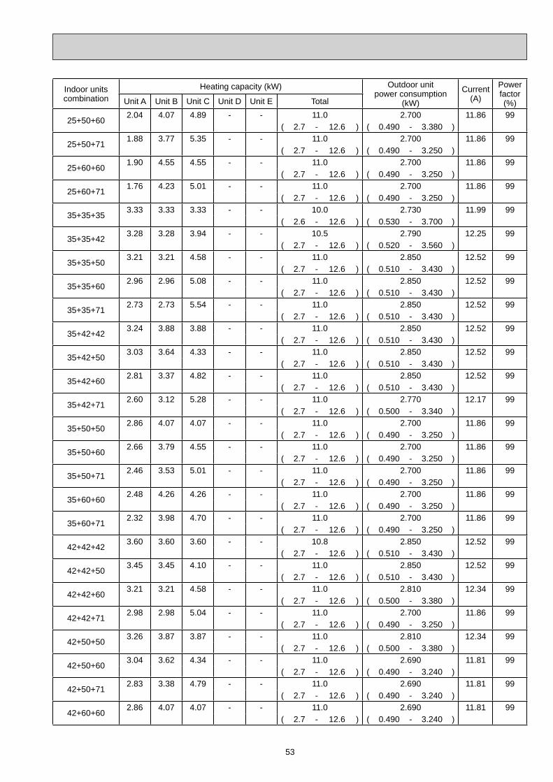
53
Indoor unitscombination
Heating capacity (kW) Outdoor unitpower consumption
(kW)
Current(A)
Powerfactor(%)Unit A Unit B Unit C Unit D Unit E Total
25+50+602.04 4.07 4.89 - - 11.0 2.700 11.86 99
( 2.7 - 12.6 ) ( 0.490 - 3.380 )
25+50+711.88 3.77 5.35 - - 11.0 2.700 11.86 99
( 2.7 - 12.6 ) ( 0.490 - 3.250 )
25+60+601.90 4.55 4.55 - - 11.0 2.700 11.86 99
( 2.7 - 12.6 ) ( 0.490 - 3.250 )
25+60+711.76 4.23 5.01 - - 11.0 2.700 11.86 99
( 2.7 - 12.6 ) ( 0.490 - 3.250 )
35+35+353.33 3.33 3.33 - - 10.0 2.730 11.99 99
( 2.6 - 12.6 ) ( 0.530 - 3.700 )
35+35+423.28 3.28 3.94 - - 10.5 2.790 12.25 99
( 2.7 - 12.6 ) ( 0.520 - 3.560 )
35+35+503.21 3.21 4.58 - - 11.0 2.850 12.52 99
( 2.7 - 12.6 ) ( 0.510 - 3.430 )
35+35+602.96 2.96 5.08 - - 11.0 2.850 12.52 99
( 2.7 - 12.6 ) ( 0.510 - 3.430 )
35+35+712.73 2.73 5.54 - - 11.0 2.850 12.52 99
( 2.7 - 12.6 ) ( 0.510 - 3.430 )
35+42+423.24 3.88 3.88 - - 11.0 2.850 12.52 99
( 2.7 - 12.6 ) ( 0.510 - 3.430 )
35+42+503.03 3.64 4.33 - - 11.0 2.850 12.52 99
( 2.7 - 12.6 ) ( 0.510 - 3.430 )
35+42+602.81 3.37 4.82 - - 11.0 2.850 12.52 99
( 2.7 - 12.6 ) ( 0.510 - 3.430 )
35+42+712.60 3.12 5.28 - - 11.0 2.770 12.17 99
( 2.7 - 12.6 ) ( 0.500 - 3.340 )
35+50+502.86 4.07 4.07 - - 11.0 2.700 11.86 99
( 2.7 - 12.6 ) ( 0.490 - 3.250 )
35+50+602.66 3.79 4.55 - - 11.0 2.700 11.86 99
( 2.7 - 12.6 ) ( 0.490 - 3.250 )
35+50+712.46 3.53 5.01 - - 11.0 2.700 11.86 99
( 2.7 - 12.6 ) ( 0.490 - 3.250 )
35+60+602.48 4.26 4.26 - - 11.0 2.700 11.86 99
( 2.7 - 12.6 ) ( 0.490 - 3.250 )
35+60+712.32 3.98 4.70 - - 11.0 2.700 11.86 99
( 2.7 - 12.6 ) ( 0.490 - 3.250 )
42+42+423.60 3.60 3.60 - - 10.8 2.850 12.52 99
( 2.7 - 12.6 ) ( 0.510 - 3.430 )
42+42+503.45 3.45 4.10 - - 11.0 2.850 12.52 99
( 2.7 - 12.6 ) ( 0.510 - 3.430 )
42+42+603.21 3.21 4.58 - - 11.0 2.810 12.34 99
( 2.7 - 12.6 ) ( 0.500 - 3.380 )
42+42+712.98 2.98 5.04 - - 11.0 2.700 11.86 99
( 2.7 - 12.6 ) ( 0.490 - 3.250 )
42+50+503.26 3.87 3.87 - - 11.0 2.810 12.34 99
( 2.7 - 12.6 ) ( 0.500 - 3.380 )
42+50+603.04 3.62 4.34 - - 11.0 2.690 11.81 99
( 2.7 - 12.6 ) ( 0.490 - 3.240 )
42+50+712.83 3.38 4.79 - - 11.0 2.690 11.81 99
( 2.7 - 12.6 ) ( 0.490 - 3.240 )
42+60+602.86 4.07 4.07 - - 11.0 2.690 11.81 99
( 2.7 - 12.6 ) ( 0.490 - 3.240 )
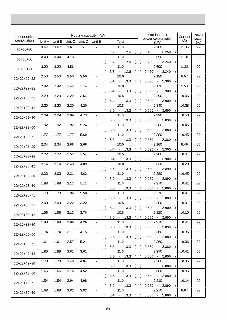
54
Indoor unitscombination
Heating capacity (kW) Outdoor unitpower consumption
(kW)
Current(A)
Powerfactor(%)Unit A Unit B Unit C Unit D Unit E Total
50+50+503.67 3.67 3.67 - - 11.0 2.700 11.86 99
( 2.7 - 12.6 ) ( 0.490 - 3.250 )
50+50+603.43 3.44 4.13 - - 11.0 2.690 11.81 99
( 2.7 - 12.6 ) ( 0.490 - 3.240 )
50+50+713.22 3.22 4.56 - - 11.0 2.690 11.81 99
( 2.7 - 12.6 ) ( 0.490 - 3.240 )
22+22+22+222.50 2.50 2.50 2.50 - 10.0 2.180 9.57 99
( 3.4 - 13.3 ) ( 0.590 - 3.900 )
22+22+22+252.42 2.42 2.42 2.74 - 10.0 2.170 9.53 99
( 3.4 - 13.3 ) ( 0.590 - 3.900 )
22+22+22+352.29 2.29 2.29 3.64 - 10.5 2.290 10.06 99
( 3.4 - 13.3 ) ( 0.590 - 3.900 )
22+22+22+422.20 2.20 2.20 4.20 - 10.8 2.340 10.28 99
( 3.5 - 13.3 ) ( 0.580 - 3.890 )
22+22+22+502.09 2.09 2.09 4.73 - 11.0 2.390 10.50 99
( 3.5 - 13.3 ) ( 0.580 - 3.890 )
22+22+22+601.92 1.92 1.92 5.24 - 11.0 2.380 10.45 99
( 3.5 - 13.3 ) ( 0.580 - 3.880 )
22+22+22+711.77 1.77 1.77 5.69 - 11.0 2.380 10.45 99
( 3.5 - 13.3 ) ( 0.580 - 3.880 )
22+22+25+252.34 2.34 2.66 2.66 - 10.0 2.160 9.49 99
( 3.4 - 13.3 ) ( 0.590 - 3.900 )
22+22+25+352.22 2.22 2.52 3.54 - 10.5 2.280 10.01 99
( 3.4 - 13.3 ) ( 0.590 - 3.900 )
22+22+25+422.14 2.14 2.43 4.09 - 10.8 2.330 10.23 99
( 3.5 - 13.3 ) ( 0.580 - 3.890 )
22+22+25+502.03 2.03 2.31 4.63 - 11.0 2.380 10.45 99
( 3.5 - 13.3 ) ( 0.580 - 3.890 )
22+22+25+601.88 1.88 2.13 5.11 - 11.0 2.370 10.41 99
( 3.5 - 13.3 ) ( 0.580 - 3.880 )
22+22+25+711.73 1.73 1.96 5.58 - 11.0 2.370 10.41 99
( 3.5 - 13.3 ) ( 0.580 - 3.880 )
22+22+35+352.03 2.03 3.22 3.22 - 10.5 2.280 10.01 99
( 3.4 - 13.3 ) ( 0.590 - 3.900 )
22+22+35+421.96 1.96 3.12 3.76 - 10.8 2.320 10.19 99
( 3.5 - 13.3 ) ( 0.580 - 3.890 )
22+22+35+501.88 1.88 2.98 4.26 - 11.0 2.370 10.41 99
( 3.5 - 13.3 ) ( 0.580 - 3.890 )
22+22+35+601.74 1.74 2.77 4.75 - 11.0 2.360 10.36 99
( 3.5 - 13.3 ) ( 0.580 - 3.880 )
22+22+35+711.61 1.61 2.57 5.21 - 11.0 2.360 10.36 99
( 3.5 - 13.3 ) ( 0.580 - 3.880 )
22+22+42+421.89 1.89 3.61 3.61 - 11.0 2.370 10.41 99
( 3.5 - 13.3 ) ( 0.580 - 3.890 )
22+22+42+501.78 1.78 3.40 4.04 - 11.0 2.360 10.36 99
( 3.5 - 13.3 ) ( 0.580 - 3.880 )
22+22+42+601.66 1.66 3.16 4.52 - 11.0 2.360 10.36 99
( 3.5 - 13.3 ) ( 0.580 - 3.880 )
22+22+42+711.54 1.54 2.94 4.98 - 11.0 2.310 10.14 99
( 3.5 - 13.3 ) ( 0.580 - 3.890 )
22+22+50+501.68 1.68 3.82 3.82 - 11.0 2.270 9.97 99
( 3.4 - 13.3 ) ( 0.550 - 3.880 )
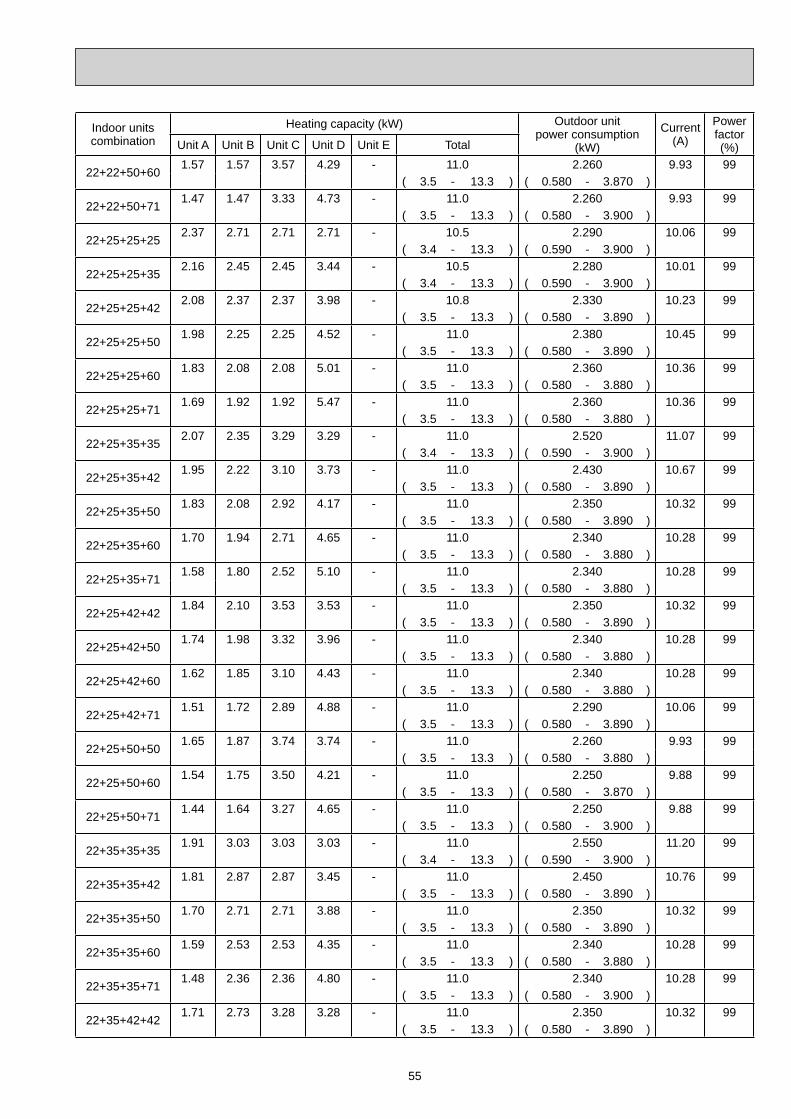
55
Indoor unitscombination
Heating capacity (kW) Outdoor unitpower consumption
(kW)
Current(A)
Powerfactor(%)Unit A Unit B Unit C Unit D Unit E Total
22+22+50+601.57 1.57 3.57 4.29 - 11.0 2.260 9.93 99
( 3.5 - 13.3 ) ( 0.580 - 3.870 )
22+22+50+711.47 1.47 3.33 4.73 - 11.0 2.260 9.93 99
( 3.5 - 13.3 ) ( 0.580 - 3.900 )
22+25+25+252.37 2.71 2.71 2.71 - 10.5 2.290 10.06 99
( 3.4 - 13.3 ) ( 0.590 - 3.900 )
22+25+25+352.16 2.45 2.45 3.44 - 10.5 2.280 10.01 99
( 3.4 - 13.3 ) ( 0.590 - 3.900 )
22+25+25+422.08 2.37 2.37 3.98 - 10.8 2.330 10.23 99
( 3.5 - 13.3 ) ( 0.580 - 3.890 )
22+25+25+501.98 2.25 2.25 4.52 - 11.0 2.380 10.45 99
( 3.5 - 13.3 ) ( 0.580 - 3.890 )
22+25+25+601.83 2.08 2.08 5.01 - 11.0 2.360 10.36 99
( 3.5 - 13.3 ) ( 0.580 - 3.880 )
22+25+25+711.69 1.92 1.92 5.47 - 11.0 2.360 10.36 99
( 3.5 - 13.3 ) ( 0.580 - 3.880 )
22+25+35+352.07 2.35 3.29 3.29 - 11.0 2.520 11.07 99
( 3.4 - 13.3 ) ( 0.590 - 3.900 )
22+25+35+421.95 2.22 3.10 3.73 - 11.0 2.430 10.67 99
( 3.5 - 13.3 ) ( 0.580 - 3.890 )
22+25+35+501.83 2.08 2.92 4.17 - 11.0 2.350 10.32 99
( 3.5 - 13.3 ) ( 0.580 - 3.890 )
22+25+35+601.70 1.94 2.71 4.65 - 11.0 2.340 10.28 99
( 3.5 - 13.3 ) ( 0.580 - 3.880 )
22+25+35+711.58 1.80 2.52 5.10 - 11.0 2.340 10.28 99
( 3.5 - 13.3 ) ( 0.580 - 3.880 )
22+25+42+421.84 2.10 3.53 3.53 - 11.0 2.350 10.32 99
( 3.5 - 13.3 ) ( 0.580 - 3.890 )
22+25+42+501.74 1.98 3.32 3.96 - 11.0 2.340 10.28 99
( 3.5 - 13.3 ) ( 0.580 - 3.880 )
22+25+42+601.62 1.85 3.10 4.43 - 11.0 2.340 10.28 99
( 3.5 - 13.3 ) ( 0.580 - 3.880 )
22+25+42+711.51 1.72 2.89 4.88 - 11.0 2.290 10.06 99
( 3.5 - 13.3 ) ( 0.580 - 3.890 )
22+25+50+501.65 1.87 3.74 3.74 - 11.0 2.260 9.93 99
( 3.5 - 13.3 ) ( 0.580 - 3.880 )
22+25+50+601.54 1.75 3.50 4.21 - 11.0 2.250 9.88 99
( 3.5 - 13.3 ) ( 0.580 - 3.870 )
22+25+50+711.44 1.64 3.27 4.65 - 11.0 2.250 9.88 99
( 3.5 - 13.3 ) ( 0.580 - 3.900 )
22+35+35+351.91 3.03 3.03 3.03 - 11.0 2.550 11.20 99
( 3.4 - 13.3 ) ( 0.590 - 3.900 )
22+35+35+421.81 2.87 2.87 3.45 - 11.0 2.450 10.76 99
( 3.5 - 13.3 ) ( 0.580 - 3.890 )
22+35+35+501.70 2.71 2.71 3.88 - 11.0 2.350 10.32 99
( 3.5 - 13.3 ) ( 0.580 - 3.890 )
22+35+35+601.59 2.53 2.53 4.35 - 11.0 2.340 10.28 99
( 3.5 - 13.3 ) ( 0.580 - 3.880 )
22+35+35+711.48 2.36 2.36 4.80 - 11.0 2.340 10.28 99
( 3.5 - 13.3 ) ( 0.580 - 3.900 )
22+35+42+421.71 2.73 3.28 3.28 - 11.0 2.350 10.32 99
( 3.5 - 13.3 ) ( 0.580 - 3.890 )
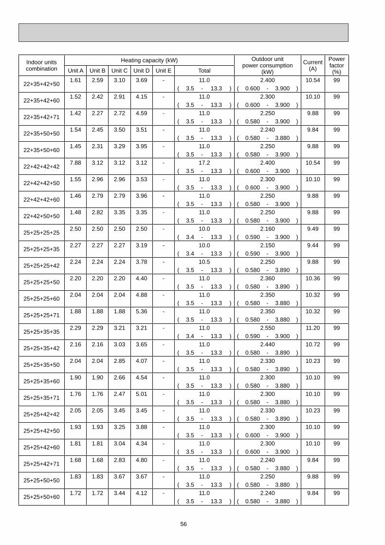
56
Indoor unitscombination
Heating capacity (kW) Outdoor unitpower consumption
(kW)
Current(A)
Powerfactor(%)Unit A Unit B Unit C Unit D Unit E Total
22+35+42+501.61 2.59 3.10 3.69 - 11.0 2.400 10.54 99
( 3.5 - 13.3 ) ( 0.600 - 3.900 )
22+35+42+601.52 2.42 2.91 4.15 - 11.0 2.300 10.10 99
( 3.5 - 13.3 ) ( 0.600 - 3.900 )
22+35+42+711.42 2.27 2.72 4.59 - 11.0 2.250 9.88 99
( 3.5 - 13.3 ) ( 0.580 - 3.900 )
22+35+50+501.54 2.45 3.50 3.51 - 11.0 2.240 9.84 99
( 3.5 - 13.3 ) ( 0.580 - 3.880 )
22+35+50+601.45 2.31 3.29 3.95 - 11.0 2.250 9.88 99
( 3.5 - 13.3 ) ( 0.580 - 3.900 )
22+42+42+427.88 3.12 3.12 3.12 - 17.2 2.400 10.54 99
( 3.5 - 13.3 ) ( 0.600 - 3.900 )
22+42+42+501.55 2.96 2.96 3.53 - 11.0 2.300 10.10 99
( 3.5 - 13.3 ) ( 0.600 - 3.900 )
22+42+42+601.46 2.79 2.79 3.96 - 11.0 2.250 9.88 99
( 3.5 - 13.3 ) ( 0.580 - 3.900 )
22+42+50+501.48 2.82 3.35 3.35 - 11.0 2.250 9.88 99
( 3.5 - 13.3 ) ( 0.580 - 3.900 )
25+25+25+252.50 2.50 2.50 2.50 - 10.0 2.160 9.49 99
( 3.4 - 13.3 ) ( 0.590 - 3.900 )
25+25+25+352.27 2.27 2.27 3.19 - 10.0 2.150 9.44 99
( 3.4 - 13.3 ) ( 0.590 - 3.900 )
25+25+25+422.24 2.24 2.24 3.78 - 10.5 2.250 9.88 99
( 3.5 - 13.3 ) ( 0.580 - 3.890 )
25+25+25+502.20 2.20 2.20 4.40 - 11.0 2.360 10.36 99
( 3.5 - 13.3 ) ( 0.580 - 3.890 )
25+25+25+602.04 2.04 2.04 4.88 - 11.0 2.350 10.32 99
( 3.5 - 13.3 ) ( 0.580 - 3.880 )
25+25+25+711.88 1.88 1.88 5.36 - 11.0 2.350 10.32 99
( 3.5 - 13.3 ) ( 0.580 - 3.880 )
25+25+35+352.29 2.29 3.21 3.21 - 11.0 2.550 11.20 99
( 3.4 - 13.3 ) ( 0.590 - 3.900 )
25+25+35+422.16 2.16 3.03 3.65 - 11.0 2.440 10.72 99
( 3.5 - 13.3 ) ( 0.580 - 3.890 )
25+25+35+502.04 2.04 2.85 4.07 - 11.0 2.330 10.23 99
( 3.5 - 13.3 ) ( 0.580 - 3.890 )
25+25+35+601.90 1.90 2.66 4.54 - 11.0 2.300 10.10 99
( 3.5 - 13.3 ) ( 0.580 - 3.880 )
25+25+35+711.76 1.76 2.47 5.01 - 11.0 2.300 10.10 99
( 3.5 - 13.3 ) ( 0.580 - 3.880 )
25+25+42+422.05 2.05 3.45 3.45 - 11.0 2.330 10.23 99
( 3.5 - 13.3 ) ( 0.580 - 3.890 )
25+25+42+501.93 1.93 3.25 3.88 - 11.0 2.300 10.10 99
( 3.5 - 13.3 ) ( 0.600 - 3.900 )
25+25+42+601.81 1.81 3.04 4.34 - 11.0 2.300 10.10 99
( 3.5 - 13.3 ) ( 0.600 - 3.900 )
25+25+42+711.68 1.68 2.83 4.80 - 11.0 2.240 9.84 99
( 3.5 - 13.3 ) ( 0.580 - 3.880 )
25+25+50+501.83 1.83 3.67 3.67 - 11.0 2.250 9.88 99
( 3.5 - 13.3 ) ( 0.580 - 3.880 )
25+25+50+601.72 1.72 3.44 4.12 - 11.0 2.240 9.84 99
( 3.5 - 13.3 ) ( 0.580 - 3.880 )
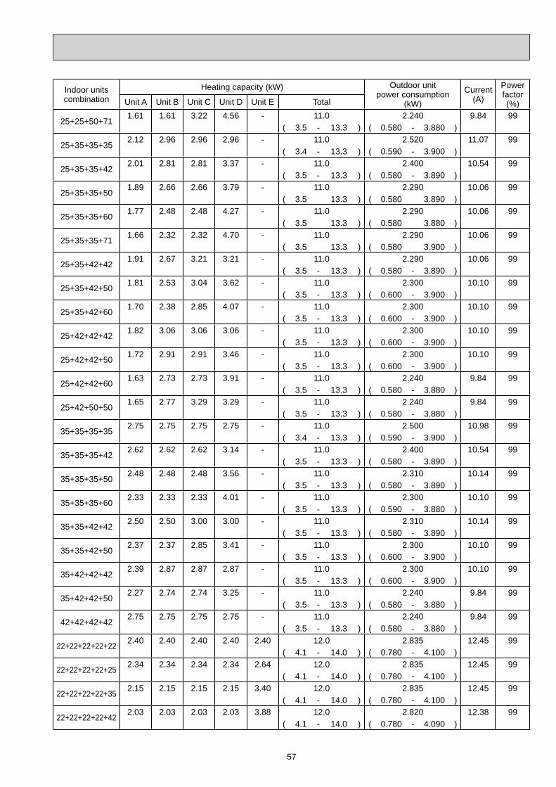
57
Indoor unitscombination
Heating capacity (kW) Outdoor unitpower consumption
(kW)
Current(A)
Powerfactor(%)Unit A Unit B Unit C Unit D Unit E Total
25+25+50+711.61 1.61 3.22 4.56 - 11.0 2.240 9.84 99
( 3.5 - 13.3 ) ( 0.580 - 3.880 )
25+35+35+352.12 2.96 2.96 2.96 - 11.0 2.520 11.07 99
( 3.4 - 13.3 ) ( 0.590 - 3.900 )
25+35+35+422.01 2.81 2.81 3.37 - 11.0 2.400 10.54 99
( 3.5 - 13.3 ) ( 0.580 - 3.890 )
25+35+35+501.89 2.66 2.66 3.79 - 11.0 2.290 10.06 99
( 3.5 13.3 ) ( 0.580 3.890 )
25+35+35+601.77 2.48 2.48 4.27 - 11.0 2.290 10.06 99
( 3.5 13.3 ) ( 0.580 3.880 )
25+35+35+711.66 2.32 2.32 4.70 - 11.0 2.290 10.06 99
( 3.5 13.3 ) ( 0.580 3.900 )
25+35+42+421.91 2.67 3.21 3.21 - 11.0 2.290 10.06 99
( 3.5 - 13.3 ) ( 0.580 - 3.890 )
25+35+42+501.81 2.53 3.04 3.62 - 11.0 2.300 10.10 99
( 3.5 - 13.3 ) ( 0.600 - 3.900 )
25+35+42+601.70 2.38 2.85 4.07 - 11.0 2.300 10.10 99
( 3.5 - 13.3 ) ( 0.600 - 3.900 )
25+42+42+421.82 3.06 3.06 3.06 - 11.0 2.300 10.10 99
( 3.5 - 13.3 ) ( 0.600 - 3.900 )
25+42+42+501.72 2.91 2.91 3.46 - 11.0 2.300 10.10 99
( 3.5 - 13.3 ) ( 0.600 - 3.900 )
25+42+42+601.63 2.73 2.73 3.91 - 11.0 2.240 9.84 99
( 3.5 - 13.3 ) ( 0.580 - 3.880 )
25+42+50+501.65 2.77 3.29 3.29 - 11.0 2.240 9.84 99
( 3.5 - 13.3 ) ( 0.580 - 3.880 )
35+35+35+352.75 2.75 2.75 2.75 - 11.0 2.500 10.98 99
( 3.4 - 13.3 ) ( 0.590 - 3.900 )
35+35+35+422.62 2.62 2.62 3.14 - 11.0 2.400 10.54 99
( 3.5 - 13.3 ) ( 0.580 - 3.890 )
35+35+35+502.48 2.48 2.48 3.56 - 11.0 2.310 10.14 99
( 3.5 - 13.3 ) ( 0.580 - 3.890 )
35+35+35+602.33 2.33 2.33 4.01 - 11.0 2.300 10.10 99
( 3.5 - 13.3 ) ( 0.590 - 3.880 )
35+35+42+422.50 2.50 3.00 3.00 - 11.0 2.310 10.14 99
( 3.5 - 13.3 ) ( 0.580 - 3.890 )
35+35+42+502.37 2.37 2.85 3.41 - 11.0 2.300 10.10 99
( 3.5 - 13.3 ) ( 0.600 - 3.900 )
35+42+42+422.39 2.87 2.87 2.87 - 11.0 2.300 10.10 99
( 3.5 - 13.3 ) ( 0.600 - 3.900 )
35+42+42+502.27 2.74 2.74 3.25 - 11.0 2.240 9.84 99
( 3.5 - 13.3 ) ( 0.580 - 3.880 )
42+42+42+422.75 2.75 2.75 2.75 - 11.0 2.240 9.84 99
( 3.5 - 13.3 ) ( 0.580 - 3.880 )
22+22+22+22+222.40 2.40 2.40 2.40 2.40 12.0 2.835 12.45 99
( 4.1 - 14.0 ) ( 0.780 - 4.100 )
22+22+22+22+252.34 2.34 2.34 2.34 2.64 12.0 2.835 12.45 99
( 4.1 - 14.0 ) ( 0.780 - 4.100 )
22+22+22+22+352.15 2.15 2.15 2.15 3.40 12.0 2.835 12.45 99
( 4.1 - 14.0 ) ( 0.780 - 4.100 )
22+22+22+22+422.03 2.03 2.03 2.03 3.88 12.0 2.820 12.38 99
( 4.1 - 14.0 ) ( 0.780 - 4.090 )

58
Indoor unitscombination
Heating capacity (kW) Outdoor unitpower consumption
(kW)
Current(A)
Powerfactor(%)Unit A Unit B Unit C Unit D Unit E Total
22+22+22+22+501.91 1.91 1.91 1.91 4.36 12.0 2.815 12.36 99
( 4.1 - 14.0 ) ( 0.790 - 4.080 )
22+22+22+22+601.78 1.78 1.78 1.78 4.88 12.0 2.805 12.32 99
( 4.1 - 14.0 ) ( 0.800 - 4.070 )
22+22+22+22+711.66 1.66 1.66 1.66 5.36 12.0 2.805 12.32 99
( 4.1 - 14.0 ) ( 0.800 - 4.070 )
22+22+22+25+252.28 2.28 2.28 2.58 2.58 12.0 2.835 12.45 99
( 4.1 - 14.0 ) ( 0.780 - 4.100 )
22+22+22+25+352.10 2.10 2.10 2.38 3.32 12.0 2.835 12.45 99
( 4.1 - 14.0 ) ( 0.780 - 4.100 )
22+22+22+25+421.98 1.98 1.98 2.26 3.80 12.0 2.820 12.38 99
( 4.1 - 14.0 ) ( 0.780 - 4.090 )
22+22+22+25+501.87 1.87 1.87 2.13 4.26 12.0 2.815 12.36 99
( 4.1 - 14.0 ) ( 0.790 - 4.080 )
22+22+22+25+601.75 1.75 1.75 1.99 4.76 12.0 2.805 12.32 99
( 4.1 - 14.0 ) ( 0.800 - 4.070 )
22+22+22+25+711.63 1.63 1.63 1.85 5.26 12.0 2.805 12.32 99
( 4.1 - 14.0 ) ( 0.800 - 4.070 )
22+22+22+35+351.94 1.94 1.94 3.09 3.09 12.0 2.835 12.45 99
( 4.1 - 14.0 ) ( 0.780 - 4.100 )
22+22+22+35+421.84 1.84 1.84 2.94 3.54 12.0 2.820 12.38 99
( 4.1 - 14.0 ) ( 0.780 - 4.090 )
22+22+22+35+501.75 1.75 1.75 2.78 3.97 12.0 2.815 12.36 99
( 4.1 - 14.0 ) ( 0.790 - 4.080 )
22+22+22+35+601.64 1.64 1.64 2.61 4.47 12.0 2.805 12.32 99
( 4.1 - 14.0 ) ( 0.800 - 4.070 )
22+22+22+35+711.53 1.53 1.53 2.44 4.97 12.0 2.805 12.32 99
( 4.1 - 14.0 ) ( 0.780 - 4.100 )
22+22+22+42+421.76 1.76 1.76 3.36 3.36 12.0 2.815 12.36 99
( 4.1 - 14.0 ) ( 0.790 - 4.080 )
22+22+22+42+501.67 1.67 1.67 3.19 3.80 12.0 2.800 12.30 99
( 4.1 - 14.0 ) ( 0.800 - 4.100 )
22+22+22+42+601.57 1.57 1.57 3.00 4.29 12.0 2.800 12.30 99
( 4.1 - 14.0 ) ( 0.800 - 4.100 )
22+22+25+25+252.22 2.22 2.52 2.52 2.52 12.0 2.835 12.45 99
( 4.1 - 14.0 ) ( 0.780 - 4.100 )
22+22+25+25+352.04 2.04 2.33 2.33 3.26 12.0 2.835 12.45 99
( 4.1 - 14.0 ) ( 0.780 - 4.100 )
22+22+25+25+421.94 1.94 2.20 2.20 3.72 12.0 2.820 12.38 99
( 4.1 - 14.0 ) ( 0.780 - 4.090 )
22+22+25+25+501.83 1.83 2.08 2.08 4.18 12.0 2.815 12.36 99
( 4.1 - 14.0 ) ( 0.790 - 4.080 )
22+22+25+25+601.71 1.71 1.95 1.95 4.68 12.0 2.805 12.32 99
( 4.1 - 14.0 ) ( 0.800 - 4.070 )
22+22+25+25+711.60 1.60 1.82 1.82 5.16 12.0 2.805 12.32 99
( 4.1 - 14.0 ) ( 0.780 - 4.100 )
22+22+25+35+351.90 1.90 2.16 3.02 3.02 12.0 2.835 12.45 99
( 4.1 - 14.0 ) ( 0.780 - 4.100 )
22+22+25+35+421.81 1.81 2.05 2.88 3.45 12.0 2.820 12.38 99
( 4.1 - 14.0 ) ( 0.780 - 4.090 )
22+22+25+35+501.71 1.71 1.95 2.73 3.90 12.0 2.815 12.36 99
( 4.1 - 14.0 ) ( 0.790 - 4.080 )

59
Indoor unitscombination
Heating capacity (kW) Outdoor unitpower consumption
(kW)
Current(A)
Powerfactor(%)Unit A Unit B Unit C Unit D Unit E Total
22+22+25+35+601.14 1.14 1.29 4.04 4.39 12.0 2.805 12.32 99
( 4.1 - 14.0 ) ( 0.780 - 4.100 )
22+22+25+42+421.72 1.72 1.96 3.30 3.30 12.0 2.815 12.36 99
( 4.1 - 14.0 ) ( 0.790 - 4.080 )
22+22+25+42+501.64 1.64 1.86 3.13 3.73 12.0 2.800 12.30 99
( 4.1 - 14.0 ) ( 0.800 - 4.100 )
22+22+25+42+601.54 1.54 1.75 2.94 4.23 12.0 2.800 12.30 99
( 4.1 - 14.0 ) ( 0.800 - 4.100 )
22+22+35+35+351.77 1.77 2.82 2.82 2.82 12.0 2.835 12.45 99
( 4.1 - 14.0 ) ( 0.780 - 4.100 )
22+22+35+35+421.69 1.69 2.69 2.69 3.24 12.0 2.820 12.38 99
( 4.1 - 14.0 ) ( 0.780 - 4.100 )
22+22+35+35+501.61 1.61 2.56 2.56 3.66 12.0 2.805 12.32 99
( 4.1 - 14.0 ) ( 0.780 - 4.100 )
22+22+35+42+421.62 1.62 2.58 3.09 3.09 12.0 2.800 12.30 99
( 4.1 - 14.0 ) ( 0.800 - 4.100 )
22+22+35+42+501.54 1.54 2.45 2.95 3.52 12.0 2.800 12.30 99
( 4.1 - 14.0 ) ( 0.800 - 4.100 )
22+22+42+42+421.56 1.56 2.96 2.96 2.96 12.0 2.800 12.30 99
( 4.1 - 14.0 ) ( 0.800 - 4.100 )
22+25+25+25+252.16 2.46 2.46 2.46 2.46 12.0 2.835 12.45 99
( 4.1 - 14.0 ) ( 0.780 - 4.100 )
22+25+25+25+352.00 2.27 2.27 2.27 3.19 12.0 2.835 12.45 99
( 4.1 - 14.0 ) ( 0.780 - 4.100 )
22+25+25+25+421.89 2.16 2.16 2.16 3.63 12.0 2.820 12.38 99
( 4.1 - 14.0 ) ( 0.780 - 4.090 )
22+25+25+25+501.80 2.04 2.04 2.04 4.08 12.0 2.815 12.36 99
( 4.1 - 14.0 ) ( 0.790 - 4.080 )
22+25+25+25+601.68 1.91 1.91 1.91 4.59 12.0 2.805 12.32 99
( 4.1 - 14.0 ) ( 0.800 - 4.070 )
22+25+25+25+711.57 1.79 1.79 1.79 5.06 12.0 2.805 12.32 99
( 4.1 - 14.0 ) ( 0.780 - 4.100 )
22+25+25+35+351.86 2.11 2.11 2.96 2.96 12.0 2.835 12.45 99
( 4.1 - 14.0 ) ( 0.780 - 4.100 )
22+25+25+35+421.78 2.01 2.01 2.82 3.38 12.0 2.820 12.38 99
( 4.1 - 14.0 ) ( 0.780 - 4.090 )
22+25+25+35+501.68 1.91 1.91 2.68 3.82 12.0 2.815 12.36 99
( 4.1 - 14.0 ) ( 0.790 - 4.080 )
22+25+25+35+601.58 1.80 1.80 2.51 4.31 12.0 2.805 12.32 99
( 4.1 - 14.0 ) ( 0.780 - 4.100 )
22+25+25+42+421.70 1.92 1.92 3.23 3.23 12.0 2.815 12.36 99
( 4.1 - 14.0 ) ( 0.790 - 4.080 )
22+25+25+42+501.61 1.83 1.83 3.07 3.66 12.0 2.805 12.32 99
( 4.1 - 14.0 ) ( 0.780 - 4.100 )
22+25+35+35+351.75 1.97 2.76 2.76 2.76 12.0 2.835 12.45 99
( 4.1 - 14.0 ) ( 0.780 - 4.100 )
22+25+35+35+421.66 1.89 2.64 2.64 3.17 12.0 2.820 12.38 99
( 4.1 - 14.0 ) ( 0.780 - 4.100 )
22+25+35+35+501.68 1.68 2.52 2.52 3.60 12.0 2.805 12.32 99
( 4.1 - 14.0 ) ( 0.780 - 4.100 )
22+25+35+42+421.59 1.80 2.53 3.04 3.04 12.0 2.805 12.32 99
( 4.1 - 14.0 ) ( 0.780 - 4.100 )

60
Indoor unitscombination
Heating capacity (kW) Outdoor unitpower consumption
(kW)
Current(A)
Powerfactor(%)Unit A Unit B Unit C Unit D Unit E Total
22+35+35+35+351.64 2.59 2.59 2.59 2.59 12.0 2.820 12.38 99
( 4.1 - 14.0 ) ( 0.780 - 4.100 )
22+35+35+35+421.55 2.49 2.49 2.49 2.98 12.0 2.805 12.32 99
( 4.1 - 14.0 ) ( 0.780 - 4.100 )
25+25+25+25+252.40 2.40 2.40 2.40 2.40 12.0 2.835 12.45 99
( 4.1 - 14.0 ) ( 0.780 - 4.100 )
25+25+25+25+352.22 2.22 2.22 2.22 3.12 12.0 2.835 12.45 99
( 4.1 - 14.0 ) ( 0.780 - 4.100 )
25+25+25+25+422.11 2.11 2.11 2.11 3.56 12.0 2.820 12.38 99
( 4.1 - 14.0 ) ( 0.780 - 4.090 )
25+25+25+25+502.00 2.00 2.00 2.00 4.00 12.0 2.815 12.36 99
( 4.1 - 14.0 ) ( 0.790 - 4.080 )
25+25+25+25+601.88 1.88 1.88 1.88 4.48 12.0 2.805 12.32 99
( 4.1 - 14.0 ) ( 0.780 - 4.100 )
25+25+25+25+711.75 1.75 1.75 1.75 5.00 12.0 2.805 12.32 99
( 4.1 - 14.0 ) ( 0.780 - 4.100 )
25+25+25+35+352.07 2.07 2.07 2.90 2.90 12.0 2.835 12.45 99
( 4.1 - 14.0 ) ( 0.780 - 4.100 )
25+25+25+35+421.97 1.97 1.97 2.76 3.33 12.0 2.820 12.38 99
( 4.1 - 14.0 ) ( 0.780 - 4.100 )
25+25+25+35+501.87 1.87 1.87 2.63 3.76 12.0 2.805 12.32 99
( 4.1 - 14.0 ) ( 0.780 - 4.100 )
25+25+25+35+601.76 1.76 1.76 2.47 4.25 12.0 2.805 12.32 99
( 4.1 - 14.0 ) ( 0.780 - 4.100 )
25+25+25+42+421.88 1.88 1.88 3.18 3.18 12.0 2.805 12.32 99
( 4.1 - 14.0 ) ( 0.780 - 4.100 )
25+25+25+42+501.79 1.79 1.79 3.03 3.60 12.0 2.805 12.32 99
( 4.1 - 14.0 ) ( 0.780 - 4.100 )
25+25+35+35+351.94 1.94 2.71 2.71 2.71 12.0 2.835 12.45 99
( 4.1 - 14.0 ) ( 0.780 - 4.100 )
25+25+35+35+421.85 1.85 2.59 2.59 3.12 12.0 2.820 12.38 99
( 4.1 - 14.0 ) ( 0.780 - 4.090 )
25+25+35+35+501.76 1.76 2.47 2.47 3.54 12.0 2.815 12.36 99
( 4.1 - 14.0 ) ( 0.790 - 4.080 )
25+25+35+42+421.77 1.77 2.50 2.98 2.98 12.0 2.805 12.32 99
( 4.1 - 14.0 ) ( 0.780 - 4.100 )
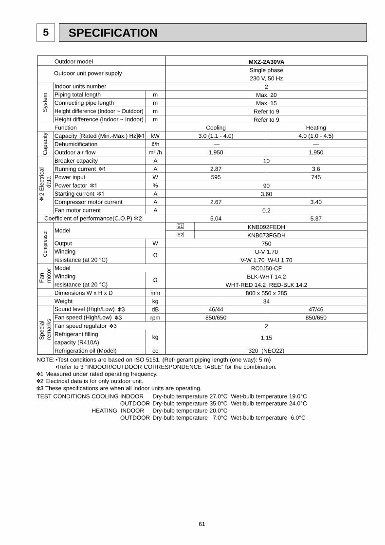
61
SPECIFICATION5
Outdoor model
Indoor units number Piping total lengthConnecting pipe lengthHeight difference (Indoor ~ Outdoor)Height difference (Indoor ~ Indoor)FunctionCapacity [Rated (Min.-Max.) Hz]DehumidificationOutdoor air flowBreaker capacityRunning currentPower input Power factorStarting currentCompressor motor currentFan motor current
Model
OutputWindingresistance (at 20 °C)ModelWindingresistance (at 20 °C)Dimensions W x H x DWeightSound level (High/Low)Fan speed (High/Low)Fan speed regulatorRefrigerant fillingcapacity (R410A)Refrigeration oil (Model)
mmmm
kW /h
m3 /hAAW%AAA
W
Ω
Ω
mmkgdBrpm
kg
cc
Com
pres
sor
2
Ele
ctric
al
d
ata
Fan
mot
orS
peci
alre
mar
ksC
apac
ityS
yste
m
Coefficient of performance(C.O.P) 2
Outdoor unit power supply
MXZ-2A30VASingle phase230 V, 50 Hz
2Max. 20Max. 15
Refer to 9Refer to 9
10
903.60
0.2
KNB092FEDHKNB073FGDH
750U-V 1.70
V-W 1.70 W-U 1.70RC0J50-CF
BLK-WHT 14.2WHT-RED 14.2 RED-BLK 14.2
800 x 550 x 28534
2
1.15
320 (NEO22)
Cooling3.0 (1.1 - 4.0)
—1,950
2.87595
2.67
5.04
46/44850/650
Heating4.0 (1.0 - 4.5)
—1,950
3.6745
3.40
5.37
47/46850/650
E1
E2
TEST CONDITIONS COOLING INDOOR Dry-bulb temperature 27.0°C Wet-bulb temperature 19.0°C OUTDOOR Dry-bulb temperature 35.0°C Wet-bulb temperature 24.0°C HEATING INDOOR Dry-bulb temperature 20.0°C OUTDOOR Dry-bulb temperature 7.0°C Wet-bulb temperature 6.0°C
NOTE: •Test conditions are based on ISO 5151. (Refrigerant piping length (one way): 5 m) •Refer to 3 “INDOOR/OUTDOOR CORRESPONDENCE TABLE” for the combination.
1 Measured under rated operating frequency.2 Electrical data is for only outdoor unit.3 These specifications are when all indoor units are operating.
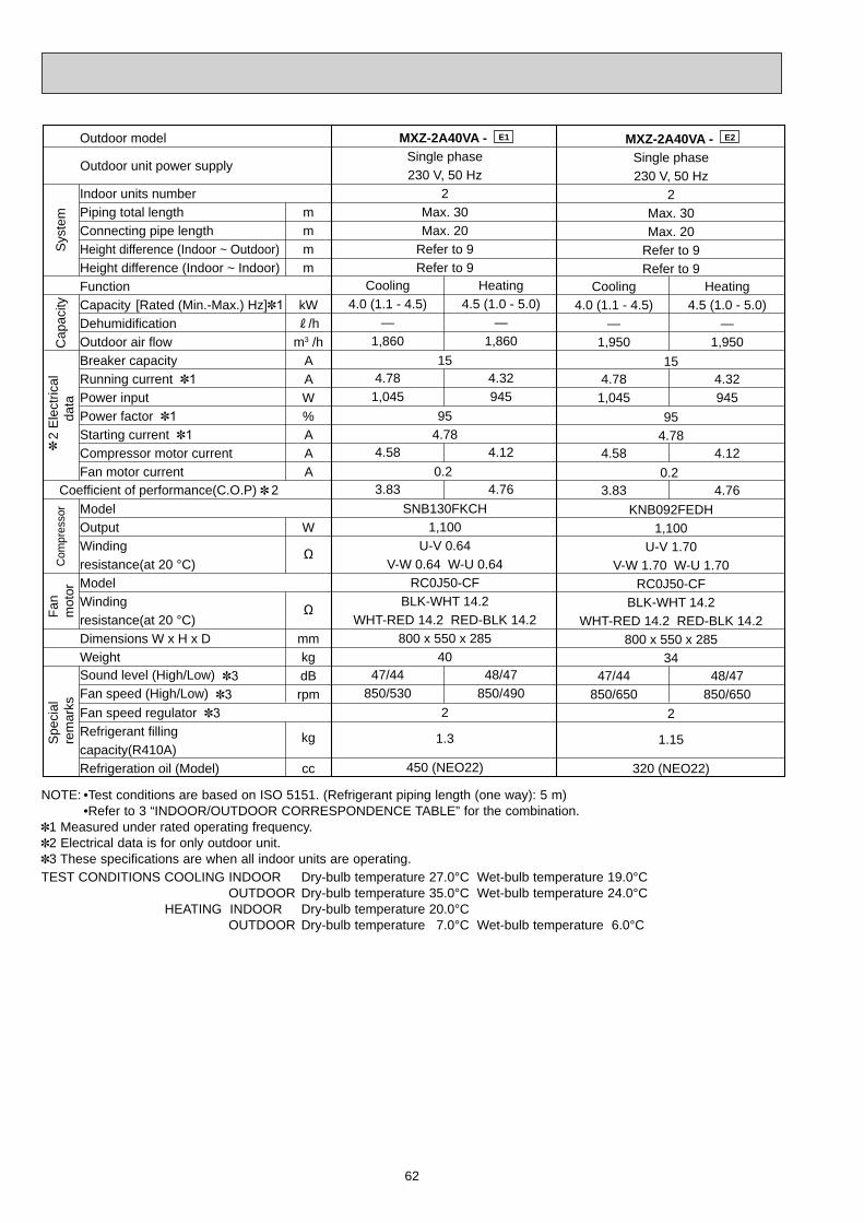
62
Outdoor model
Indoor units number Piping total lengthConnecting pipe lengthHeight difference (Indoor ~ Outdoor)Height difference (Indoor ~ Indoor)FunctionCapacity [Rated (Min.-Max.) Hz] DehumidificationOutdoor air flow Breaker capacity Running current Power input Power factor Starting currentCompressor motor current Fan motor current
ModelOutputWindingresistance(at 20 °C)ModelWindingresistance(at 20 °C)Dimensions W x H x DWeightSound level (High/Low)Fan speed (High/Low)Fan speed regulatorRefrigerant fillingcapacity(R410A)Refrigeration oil (Model)
mmmm
kW /h
m3 /hAAW%AAA
W
Ω
Ω
mmkgdBrpm
kg
cc
Com
pres
sor
2
Ele
ctric
al
d
ata
Fan
mot
orS
peci
alre
mar
ksC
apac
ityS
yste
m
Coefficient of performance(C.O.P) 2
MXZ-2A40VA - Single phase230 V, 50 Hz
2Max. 30Max. 20
Refer to 9Refer to 9
15
954.78
0.2
SNB130FKCH1,100
U-V 0.64V-W 0.64 W-U 0.64
RC0J50-CFBLK-WHT 14.2
WHT-RED 14.2 RED-BLK 14.2800 x 550 x 285
40
2
1.3
450 (NEO22)
Heating4.5 (1.0 - 5.0)
—1,860
4.32945
4.12
4.76
48/47850/490
MXZ-2A40VA - Single phase230 V, 50 Hz
2Max. 30Max. 20
Refer to 9Refer to 9
15
954.78
0.2
KNB092FEDH1,100
U-V 1.70V-W 1.70 W-U 1.70
RC0J50-CFBLK-WHT 14.2
WHT-RED 14.2 RED-BLK 14.2800 x 550 x 285
34
2
1.15
320 (NEO22)
Cooling4.0 (1.1 - 4.5)
—1,950
4.781,045
4.58
3.83
47/44850/650
Heating4.5 (1.0 - 5.0)
—1,950
4.32945
4.12
4.76
48/47850/650
Cooling4.0 (1.1 - 4.5)
—1,860
4.781,045
4.58
3.83
47/44850/530
E1 E2
Outdoor unit power supply
TEST CONDITIONS COOLING INDOOR Dry-bulb temperature 27.0°C Wet-bulb temperature 19.0°C OUTDOOR Dry-bulb temperature 35.0°C Wet-bulb temperature 24.0°C HEATING INDOOR Dry-bulb temperature 20.0°C OUTDOOR Dry-bulb temperature 7.0°C Wet-bulb temperature 6.0°C
NOTE: •Test conditions are based on ISO 5151. (Refrigerant piping length (one way): 5 m) •Refer to 3 “INDOOR/OUTDOOR CORRESPONDENCE TABLE” for the combination.
1 Measured under rated operating frequency.2 Electrical data is for only outdoor unit.3 These specifications are when all indoor units are operating.
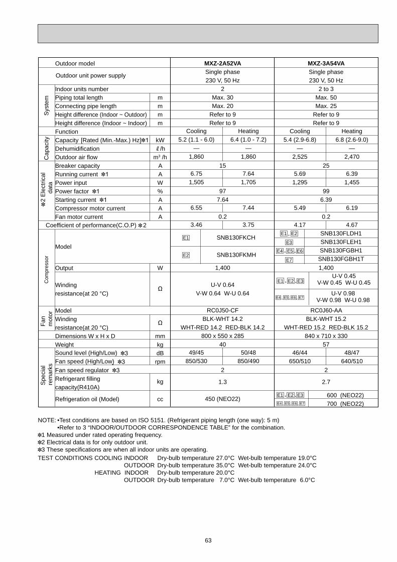
63
Outdoor model
Indoor units number Piping total lengthConnecting pipe lengthHeight difference (Indoor ~ Outdoor)Height difference (Indoor ~ Indoor)FunctionCapacity [Rated (Min.-Max.) Hz]DehumidificationOutdoor air flow Breaker capacity Running currentPower inputPower factorStarting currentCompressor motor currentFan motor current
Model
Output
Windingresistance(at 20 °C)
ModelWindingresistance(at 20 °C)Dimensions W x H x DWeightSound level (High/Low)Fan speed (High/Low)Fan speed regulatorRefrigerant fillingcapacity(R410A)
Refrigeration oil (Model)
MXZ-2A52VASingle phase230 V, 50 Hz
2Max. 30Max. 20
Refer to 9Refer to 9
15
977.64
0.2
1,400
U-V 0.64V-W 0.64 W-U 0.64
RC0J50-CFBLK-WHT 14.2
WHT-RED 14.2 RED-BLK 14.2800 x 550 x 285
40
2
1.3
450 (NEO22)
Cooling5.2 (1.1 - 6.0)
—1,860
6.751,505
6.55
3.46
49/45850/530
Heating6.4 (1.0 - 7.2)
—1,860
7.641,705
7.44
3.75
50/48850/490
U-V 0.45V-W 0.45 W-U 0.45
U-V 0.98V-W 0.98 W-U 0.98
mmmm
kW /h
m3 /hAAW%AAA
W
Ω
Ω
mmkgdBrpm
kg
cc
Com
pres
sor
2
Ele
ctric
al
d
ata
Fan
mot
orS
peci
alre
mar
ksC
apac
ityS
yste
m
Coefficient of performance(C.O.P) 2
Outdoor unit power supply
MXZ-3A54VASingle phase230 V, 50 Hz
2 to 3Max. 50Max. 25
Refer to 9Refer to 9
25
996.39
0.2
1,400
RC0J60-AABLK-WHT 15.2
WHT-RED 15.2 RED-BLK 15.2840 x 710 x 330
57
2
2.7
600 (NEO22) 700 (NEO22)
Cooling5.4 (2.9-6.8)
—2,525
5.691,295
5.49
4.17
46/44650/510
Heating6.8 (2.6-9.0)
—2,470
6.391,455
6.19
4.67
48/47640/510
SNB130FLDH1SNB130FLEH1SNB130FGBH1
SNB130FGBH1T
SNB130FKCH
SNB130FKMH
E1
E2
E2E1
E3
E2E1 E3
E2E1 E3
,
, ,
, ,
E5E4 , E6, E7,
E5E4 , E6, E7,
E7
E5E4 E6, ,
TEST CONDITIONS COOLING INDOOR Dry-bulb temperature 27.0°C Wet-bulb temperature 19.0°C OUTDOOR Dry-bulb temperature 35.0°C Wet-bulb temperature 24.0°C HEATING INDOOR Dry-bulb temperature 20.0°C OUTDOOR Dry-bulb temperature 7.0°C Wet-bulb temperature 6.0°C
NOTE: •Test conditions are based on ISO 5151. (Refrigerant piping length (one way): 5 m) •Refer to 3 “INDOOR/OUTDOOR CORRESPONDENCE TABLE” for the combination.
1 Measured under rated operating frequency.2 Electrical data is for only outdoor unit.3 These specifications are when all indoor units are operating.

64
MXZ-4A71VASingle phase230 V, 50 Hz
2 to 4Max. 60Max. 25
Refer to 9Refer to 9
25
998.56
0.2
2,000
RC0J60-AABLK-WHT 15.2
WHT-RED 15.2 RED-BLK 15.2840 x 710 x 330
58
2
2.7
600 (NEO22) 700 (NEO22)
Heating8.6 (3.4-9.0)
—2,790
8.561,950
8.36
4.41
50/48700/510
SNB130FLDH1SNB130FLEH1SNB130FGBH1
SNB130FGBH1T
Outdoor model
Indoor units number Piping total lengthConnecting pipe lengthHeight difference (Indoor ~ Outdoor)Height difference (Indoor ~ Indoor)FunctionCapacity [Rated (Min.-Max.) Hz]DehumidificationOutdoor air flow Breaker capacity Running currentPower inputPower factorStarting currentCompressor motor current Fan motor current
Model
Output
Windingresistance (at 20 °C)
ModelWindingresistance (at 20°C)Dimensions W x H x D
Weight
Sound level (High/Low)Fan speed (High/Low)Fan speed regulatorRefrigerant fillingcapacity (R410A)
Refrigeration oil (Model)
mmmm
kW /h
m3 /hAAW%AAA
W
Ω
Ω
mm
kg
dBrpm
kg
cc
Com
pres
sor
2
Ele
ctric
al
d
ata
Fan
mot
orS
peci
alre
mar
ksC
apac
ityS
yste
m
Coefficient of performance(C.O.P) 2
MXZ-4A80VASingle phase230 V, 50 Hz
2 to 4Max. 70Max. 25
Refer to 9Refer to 9
25
999.62
0.2
TNB220FMCH
2,100
U-V 1.41V-W 1.41 W-U 1.41
PM8H60-UABLK-WHT 15.2
WHT-RED 15.2 RED-BLK 15.2900 x 900 x 320
70 67
2
3.5
870 (NEO22)
Cooling8.0 (3.7-9.2)
—2,530
9.622,190
9.42
3.65
46/44560/400
Heating9.4 (3.4-11.6)
—2,630
8.481,930
8.28
4.87
48/46590/400
U-V 0.45V-W 0.45 W-U 0.45
U-V 0.98V-W 0.98 W-U 0.98
Outdoor unit power supply
Cooling7.1 (3.7-8.8)
—2,525
8.481,930
8.28
3.68
48/45650/510
, ,
E1 , E2
E3
E2E1 E3
E2E1 E3, ,
E7
E5E4 E6, ,
E1
E2
E5E4 , E6, E7,
E5E4 , E6, E7,
TEST CONDITIONS COOLING INDOOR Dry-bulb temperature 27.0°C Wet-bulb temperature 19.0°C OUTDOOR Dry-bulb temperature 35.0°C Wet-bulb temperature 24.0°C HEATING INDOOR Dry-bulb temperature 20.0°C OUTDOOR Dry-bulb temperature 7.0°C Wet-bulb temperature 6.0°C
NOTE: •Test conditions are based on ISO 5151. (Refrigerant piping length (one way): 5 m) •Refer to 3 “INDOOR/OUTDOOR CORRESPONDENCE TABLE” for the combination.
1 Measured under rated operating frequency.2 Electrical data is for only outdoor unit.3 These specifications are when all indoor units are operating.
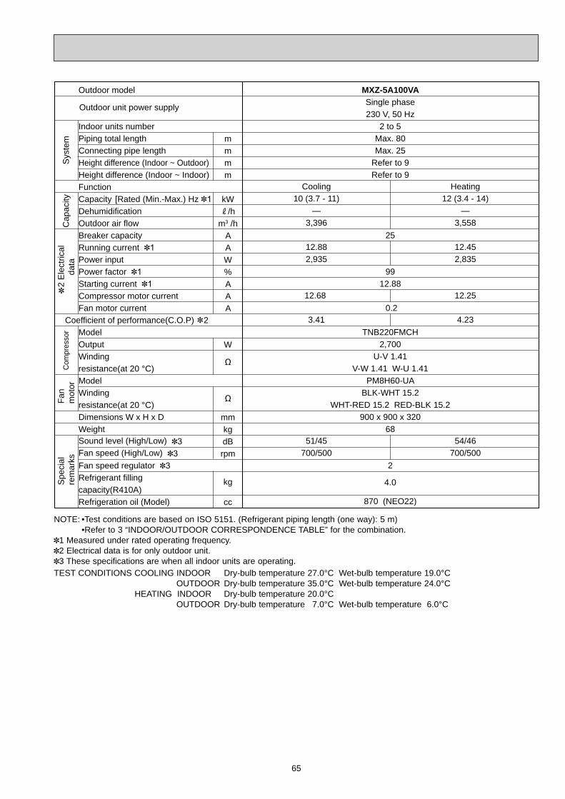
65
Outdoor model
Indoor units number Piping total lengthConnecting pipe lengthHeight difference (Indoor ~ Outdoor)Height difference (Indoor ~ Indoor)FunctionCapacity [Rated (Min.-Max.) HzDehumidificationOutdoor air flow Breaker capacity Running currentPower inputPower factorStarting currentCompressor motor current Fan motor current
ModelOutputWindingresistance(at 20 °C)ModelWindingresistance(at 20 °C)Dimensions W x H x DWeightSound level (High/Low)Fan speed (High/Low)Fan speed regulatorRefrigerant fillingcapacity(R410A)Refrigeration oil (Model)
mmmm
kW /h
m3 /hAAW%AAA
W
Ω
Ω
mmkgdBrpm
kg
cc
Com
pres
sor
2
Ele
ctric
al
d
ata
Fan
mot
orS
peci
alre
mar
ksC
apac
ityS
yste
m
Coefficient of performance(C.O.P) 2
Outdoor unit power supply
MXZ-5A100VASingle phase230 V, 50 Hz
2 to 5Max. 80Max. 25
Refer to 9Refer to 9
25
9912.88
0.2
TNB220FMCH2,700
U-V 1.41V-W 1.41 W-U 1.41
PM8H60-UABLK-WHT 15.2
WHT-RED 15.2 RED-BLK 15.2900 x 900 x 320
68
2
4.0
870 (NEO22)
Cooling10 (3.7 - 11)
—3,396
12.882,935
12.68
3.41
51/45700/500
Heating12 (3.4 - 14)
—3,558
12.452,835
12.25
4.23
54/46700/500
TEST CONDITIONS COOLING INDOOR Dry-bulb temperature 27.0°C Wet-bulb temperature 19.0°C OUTDOOR Dry-bulb temperature 35.0°C Wet-bulb temperature 24.0°C HEATING INDOOR Dry-bulb temperature 20.0°C OUTDOOR Dry-bulb temperature 7.0°C Wet-bulb temperature 6.0°C
NOTE: •Test conditions are based on ISO 5151. (Refrigerant piping length (one way): 5 m) •Refer to 3 “INDOOR/OUTDOOR CORRESPONDENCE TABLE” for the combination.
1 Measured under rated operating frequency.2 Electrical data is for only outdoor unit.3 These specifications are when all indoor units are operating.

66
NOISE CRITERIA CURVES6
90
80
70
60
50
40
30
20
1063 125 250 500 1000 2000 4000 8000
APPROXIMATETHRESHOLD OFHEARING FORCONTINUOUSNOISE
NC-60
NC-50
NC-40
NC-30
NC-20
NC-70
OC
TAVE
BA
ND
SO
UN
D P
RES
SUR
E LE
VEL,
0dB
= 0
.000
2 M
ICR
O B
AR
BAND CENTER FREQUENCIES, Hz
CoolingHigh
FUNCTIONFAN SPEED
HeatingHigh
49
SPL(dB(A))
50
LINE
90
80
70
60
50
40
30
20
1063 125 250 500 1000 2000 4000 8000
APPROXIMATETHRESHOLD OFHEARING FORCONTINUOUSNOISE
NC-60
NC-50
NC-40
NC-30
NC-20
NC-70
OC
TAVE
BA
ND
SO
UN
D P
RES
SUR
E LE
VEL,
0dB
= 0
.000
2 M
ICR
O B
AR
BAND CENTER FREQUENCIES, Hz
CoolingHigh
FUNCTIONFAN SPEED
HeatingHigh
47
SPL(dB(A))
48
LINEMXZ-2A40VA
MXZ-2A52VA
90
80
70
60
50
40
30
20
1063 125 250 500 1000 2000 4000 8000
APPROXIMATETHRESHOLD OFHEARING FORCONTINUOUSNOISE
NC-60
NC-50
NC-40
NC-30
NC-20
NC-70
OC
TAVE
BA
ND
SO
UN
D P
RES
SUR
E LE
VEL,
0dB
= 0
.000
2 M
ICR
O B
AR
BAND CENTER FREQUENCIES, Hz
CoolingHigh
FUNCTIONFAN SPEED
HeatingHigh
46
SPL(dB(A))
48
LINEMXZ-3A54VA
MXZ-2A30VA
90
80
70
60
50
40
30
20
1063 125 250 500 1000 2000 4000 8000
APPROXIMATETHRESHOLD OFHEARING FORCONTINUOUSNOISE
NC-60
NC-50
NC-40
NC-30
NC-20
NC-70
OC
TAVE
BA
ND
SO
UN
D P
RES
SUR
E LE
VEL,
0dB
= 0
.000
2 M
ICR
O B
AR
BAND CENTER FREQUENCIES, Hz
CoolingHigh
FUNCTIONFAN SPEED
HeatingHigh
46
SPL(dB(A))
47
LINE

67
90
80
70
60
50
40
30
20
1063 125 250 500 1000 2000 4000 8000
APPROXIMATETHRESHOLD OFHEARING FORCONTINUOUSNOISE
NC-60
NC-50
NC-40
NC-30
NC-20
NC-70
OC
TAVE
BA
ND
SO
UN
D P
RES
SUR
E LE
VEL,
0dB
= 0
.000
2 M
ICR
O B
AR
BAND CENTER FREQUENCIES, Hz
CoolingHigh
FUNCTIONFAN SPEED
HeatingHigh
46
SPL(dB(A))
48
LINEMXZ-4A80VA
OUTDOOR UNIT
MICROPHONE1m
Test conditions Cooling :Dry-bulb temperature 35°C Wet-bulb temperature 24°C Heating :Dry-bulb temperature 7°C Wet-bulb temperature 6°C
90
80
70
60
50
40
30
20
1063 125 250 500 1000 2000 4000 8000
APPROXIMATETHRESHOLD OFHEARING FORCONTINUOUSNOISE
NC-60
NC-50
NC-40
NC-30
NC-20
NC-70
OC
TAVE
BA
ND
SO
UN
D P
RES
SUR
E LE
VEL,
0dB
= 0
.000
2 M
ICR
O B
AR
BAND CENTER FREQUENCIES, Hz
CoolingHigh
FUNCTIONFAN SPEED
HeatingHigh
48
SPL(dB(A))
50
LINEMXZ-4A71VA
90
80
70
60
50
40
30
20
1063 125 250 500 1000 2000 4000 8000
APPROXIMATETHRESHOLD OFHEARING FORCONTINUOUSNOISE
NC-60
NC-50
NC-40
NC-30
NC-20
NC-70
OC
TAVE
BA
ND
SO
UN
D P
RES
SUR
E LE
VEL,
0dB
= 0
.000
2 M
ICR
O B
AR
BAND CENTER FREQUENCIES, Hz
CoolingHigh
FUNCTIONFAN SPEED
HeatingHigh
51
SPL(dB(A))
54
LINEMXZ-5A100VA

68
OUTLINES AND DIMENSIONS7
Unit: mmMXZ-2A30VAMXZ-2A40VAMXZ-2A52VA
5151
170.4
44
400
304
325
344.
5
17.5
40
22.3
550
280
10
800
500150
302.5
1323 285
51
251.
1
69
handle
Air in
Air out
2-10x21 Oval hole
Drainage hole 42
Liquid pipe : 6.35(flared)1/4Gas pipe : 9.52(flared)3/8Liquid pipe : 6.35(flared)1/4Gas pipe : 9.52(flared)3/8
B unit connection
A unit connection
REQUIRED SPACE Basically open 100mm or more without any obstruction in front and on both sides of the unit.
350mm or more200mm or more
100mm or more
100mm or more
Open two sides of left, right, or rear side.

69
Unit: mm
84
360
121
225
45
66.3
17.7
17.7
360.
6
396
3831
500
288233.163.2
31.3
16.8
1330 330
25
27.1
30840
710
440
23.1
4-10 x 21 Oval hole
Air out
Air in
Air in
Liquid pipe 6.35(flared)1/4
Gas pipe 9.52(flared)3/8(A,B,C unit)
C unit connection
B unit connection
A unit connection
Indoor andoutdoorconnect wiring39 x 27 hole
Drainage holes 3- 33
MXZ-3A54VA - E1 , E2 , E3 , E4
REQUIRED SPACE
More than 100 mm
Open as a ruleMore than 500 mmif the front and bothsides are open
More than 100 mmMore than 200 mm ifthere are obstacles toboth sides
Open as a ruleMore than 500 mm ifthe back, both sidesand top are open
More than 350 mm
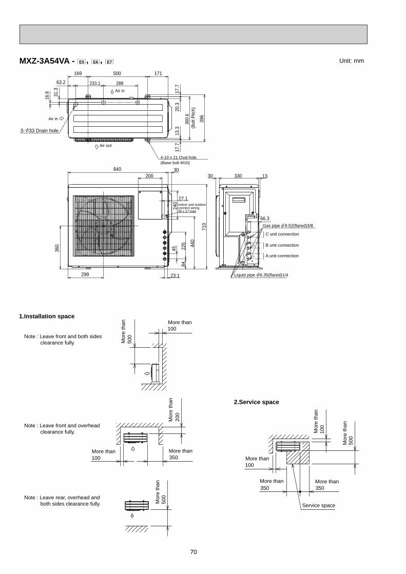
70
100
500
350350
100
500
100
100 350
200
500
Service space
More thanMore than
More than
Mor
e th
an
Mor
e th
an
Mor
e th
an
More than More than
Mor
e th
an
Mor
e th
an More than1.Installation space
Note : Leave front and both sides clearance fully.
Note : Leave front and overhead clearance fully.
Note : Leave rear, overhead and both sides clearance fully.
2.Service space
(Bol
t Pitc
h)
4-10 x 21 Oval hole(Base bolt M10)
Air in
Air in
Air out
3- 33 Drain hole
31.3
13.3
20.3
171500169
63.2
360.
6
16.8
288233.1
17.7
17.7
396
30 330
66.3
840 30
710
299
360
240
200
Indoor and outdoor connect wiring 39 x 27 hole
27.1
23.1
45 225
84
440
Gas pipe 9.52(flared)3/8
Liquid pipe 6.35(flared)1/4
C unit connection
B unit connection
A unit connection
13
Unit: mmMXZ-3A54VA - E5 , E6 , E7
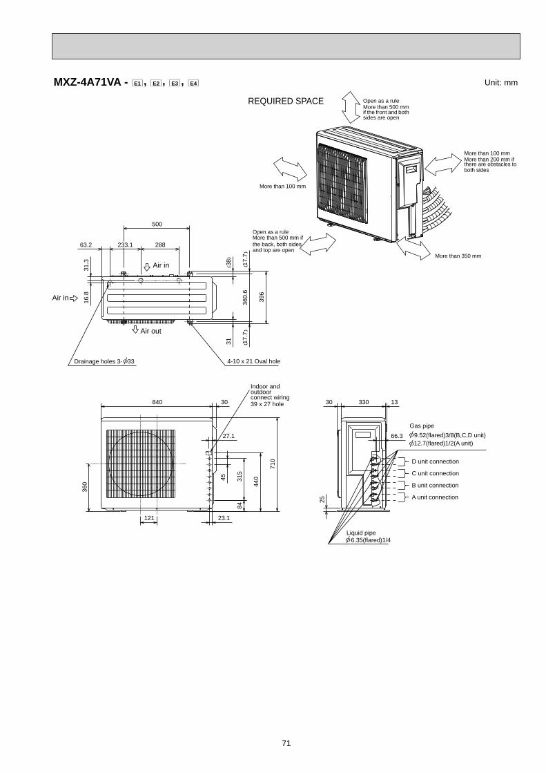
71
Unit: mmMXZ-4A71VA - E1 , E2 , E3 , E4
84
360
121
17.7
17.7
360.
6
396
3831
500
288233.163.2
31.3
16.8
1330 330
25
66.327.1
30840
710
44045 31
5
23.1
Drainage holes 3- 33 4-10 x 21 Oval hole
Air out
Air in
Air in
Liquid pipe 6.35(flared)1/4
Gas pipe 9.52(flared)3/8(B,C,D unit) 12.7(flared)1/2(A unit)
D unit connection
C unit connection
B unit connection
A unit connection
Indoor andoutdoorconnect wiring39 x 27 hole
REQUIRED SPACE
More than 100 mm
Open as a ruleMore than 500 mmif the front and bothsides are open
More than 100 mmMore than 200 mm ifthere are obstacles toboth sides
Open as a ruleMore than 500 mm ifthe back, both sidesand top are open
More than 350 mm
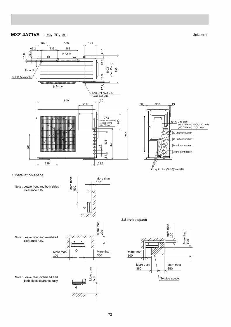
72
MXZ-4A71VA - E5 , E6 , E7
100
500
350350
100
500
100
100 350
200
500 Service space
More thanMore than
More than
Mor
e th
an
Mor
e th
an
Mor
e th
an
More than More than
Mor
e th
an
Mor
e th
an More than1.Installation space
Note : Leave front and both sides clearance fully.
Note : Leave front and overhead clearance fully.
Note : Leave rear, overhead and both sides clearance fully.
2.Service space
Air in
Air in
Air out
(Base bolt M10)4-10 x 21 Oval hole
3- 33 Drain hole (Bol
t Pitc
h)
171500
360.
6
20.3
13.3
16.8 31
.3
63.2 288233.1
169
396
17.7
17.7
9.52(flared)3/8(B,C,D unit)
Liquid pipe 6.35(flared)1/4
330 1330
66.3Indoor and outdoor connect wiring 39 x 27 hole
27.1
23.1
440
45
315
84
299
360
710
840 30200
240
D unit connection
C unit connection
B unit connection
A unit connection
12.7(flared)1/2(A unit)
Gas pipe
Unit: mm

73
MXZ-4A80VA - E1 Unit: mm
100
500
350350
100
500
100
100 350
200
500
Service space
More thanMore than
More than
Mor
e th
an
Mor
e th
an
Mor
e th
an
More than More than
Mor
e th
an
Mor
e th
an More than
(200)
(16)
(27)
355
(16)
387
40
200 500
250 27035
3574
Air in
Drainage holes 3- 33Air out
Air in
(Base bolt M10)2-U-shape notched holes
(Base bolt M10)2-12 x 36 Oval hole
531.
3
900
480.
8350
900
460
317
50
23
Indoor andoutdoorconnect wiring26 x 45 hole
3033
320
23
10
88
Gas pipe
12.7(flared)1/2(A unit) 9.52(flared)3/8(B,C,D unit)
6.35(flared)1/4Liquid pipe
D unit connectionC unit connectionB unit connectionA unit connection
1.Installation space
Note : Leave front and both sides clearance fully.
Note : Leave front and overhead clearance fully.
Note : Leave rear, overhead and both sides clearance fully.
2.Service space

74
MXZ-4A80VA - E2 MXZ-5A100VA Unit: mm46
0
317
900
Air out
900
HandleHandle
3574
200 200500
35 250 270
355
(Bol
t pitc
h)38
7
4027 16
1611
243- 33 Drain hole
(Base bolt M10)
(Base bolt M10)2-U Shaped notched hole
2-12 x 36 Oval hole
Air in
Air in
B
A
100
500
350350
100
500
100
100 350
200
500
Service space
More thanMore than
More than
Mor
e th
an
Mor
e th
an
Mor
e th
an
More than More than
Mor
e th
an
Mor
e th
an More than
32030 10
88
Gas pipe
12.7(flared) 1/2 (A unit) 9.52(flared) 3/8 (B,C,D,E (MXZ-5A100VA) unit)
6.35(flared)1/4Liquid pipe
D unit connectionE unit connection (MXZ-5A100VA)
C unit connectionB unit connectionA unit connection
1.Installation space
Note : Leave front and both sides clearance fully.
Note : Leave front and overhead clearance fully.
Note : Leave rear, overhead and both sides clearance fully.
2.Service space
23
597
132
405
45
Indoor and outdoorconnectwiring(35 x 53) hole
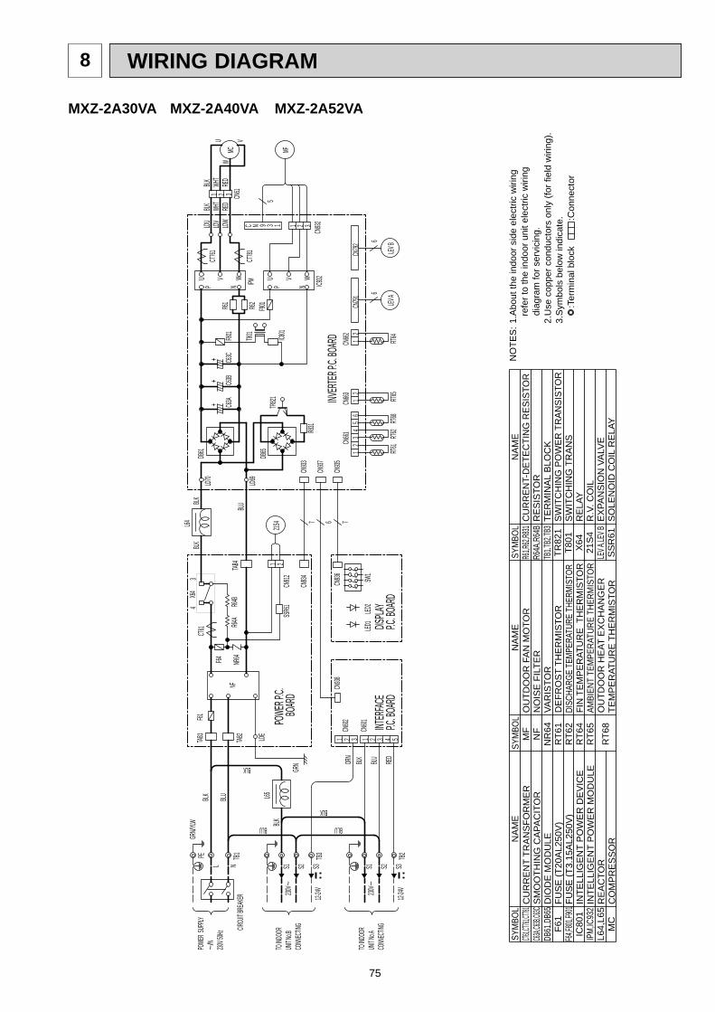
75
WIRING DIAGRAM8
MXZ-2A30VA MXZ-2A40VA MXZ-2A52VA
C N 9 3 1
CN792
CN791
12
CN662
CN663 2
15
43
21
CN661
6
LEV A
LEV B
66
RT64
RT65
RT62
RT61
RT68
321
CN932
MF
F901
T801
IC801
C63C
C63B
C63A
F801
IPMR62R61
P N
U V WCT
781
321LDWLDVLDU
CN61
BLK WHT
RED
TR821
CT761
DB61
DB65
R831
MCU
W
V
BLK WHT
RED
INVER
TER P.C
. BOAR
D
LD70
LD69
BLK3
4L64
BLK
P NWVU
IC932
CN933
CN937
CN935
CN934
TAB4
6 7
5
CT61
NR64F64
R64A
R64B
21S4
1 2SS
R61CN
912
X64
NF
POWE
R P.C.
BO
ARD
F61TAB
1
TAB2
LDE
L N
PE
S3S2S1
L65
1 2 3 4321 5
CN602
CN601
CN938
INTER
FACE
P.C. BO
ARD
TB1 TB2
POWE
R SUP
PLY~/
N230
V 50Hz
TO IND
OOR
UNIT N
o.ACO
NNEC
TING
12-24V230
V~
CIRCU
IT BRE
AKER
TO IND
OOR
UNIT N
o.BCO
NNEC
TING
230V~
S1 S2
12-24V
TB3S3
ORN
BLK BLU RED
BLU
BLK
BLKBLU
BLK
BLUBLKGR
N /YLW
GRN
DISPLA
YP.C
. BOAR
D
LED2
SW1
CN936
LED1
BLU
7
++
+
:Ter
min
al b
lock
:C
onne
ctor
3.S
ymbo
ls b
elow
indi
cate
.2.
Use
cop
per c
ondu
ctor
s on
ly (f
or fi
eld
wiri
ng).
dia
gram
for s
ervi
cing
. r
efer
to th
e in
door
uni
t ele
ctric
wiri
ng1.
Abo
ut th
e in
door
sid
e el
ectri
c w
iring
NO
TES
:SY
MBO
LN
AM
ESY
MBO
LN
AM
ECT6
1,CT761
,CT781
C63A,C
63B,C6
3CDB
61,D
B65
F61
F64,F8
01,F90
1IC
801
IPM,
IC93
2L6
4,L6
5M
C
MF
NF
NR
64R
T61
RT6
2R
T64
RT6
5R
T68
OU
TDO
OR
FA
N M
OTO
RN
OIS
E F
ILTE
RVA
RIS
TOR
DE
FRO
ST
THE
RM
ISTO
RDI
SCHA
RGE
TEMP
ERAT
URE
THER
MIST
ORFI
N T
EMPE
RAT
UR
E T
HER
MIS
TOR
AMBI
ENT
TEM
PERA
TURE
THE
RMIS
TOR
OU
TDO
OR
HE
AT E
XC
HA
NG
ER
TE
MP
ER
ATU
RE
TH
ER
MIS
TOR
NA
ME
SYM
BOL
R61,R
62,R8
31R6
4A,R
64B
TB1,T
B2,TB
3TR
821
T801
X64
21S
4LE
V A,LE
V BS
SR
61
CU
RR
ENT-
DET
ECTI
NG
RES
ISTO
RR
ES
ISTO
RTE
RM
INA
L B
LOC
KSW
ITC
HIN
G P
OW
ER T
RAN
SIST
OR
SW
ITC
HIN
G T
RA
NS
RE
LAY
R.V
. CO
ILE
XPA
NS
ION
VA
LVE
SO
LEN
OID
CO
IL R
ELA
Y
CU
RR
EN
T TR
AN
SFO
RM
ER
SM
OO
THIN
G C
APA
CIT
OR
DIO
DE
MO
DU
LEFU
SE
(T20
AL2
50V
)FU
SE
(T3.
15A
L250
V)
INTE
LLIG
EN
T P
OW
ER
DE
VIC
EIN
TELL
IGE
NT
PO
WE
R M
OD
ULE
RE
AC
TOR
CO
MP
RE
SS
OR

76
R64
B
21S
4
BLU
BLU
12
W RT64
(BLU
)(R
ED
)(W
HT)
3
WHT
RED
LD9
GR
N
TAB
1
TAB
2
CN6013 2 1
CN6023 2123
CN6031
REDBRNBLUORNYLWWHT
CN
791
14
32
56
CN
792
14
32
56
REDBRNBLUORNYLWWHT
14
32
56
CN
793
WHTYLWORNBLUBRNRED
CN
663
12
RT6
CR
T6A
GRYGRYGRYGRYGRYGRY
23
45
61
78
CN
662
GRYGRY R
T61
76
54
32
18
CN
661
E
REDBRNBLUORNYLWWHT
LEV
CN
795
65
23
41
54321321
MF
CN
931
CN
932
GR
NG
RN
LDE
2LD
E1
21CN5
765CN2
2 3 41
21CN
4LD
2LD
1
WH
T
RE
D
MCV
U BLK
WVU CN312
BLK
BLK
HC
930
BLK
BLKBLKBLK
BLKBLK
BLK
BLK
BLK
BLK WH
TR
ED
YLW BLU OR
NP
NK
GR
Y
BLKBLK
GRYGRY
T801
R93
7B
R93
7A
RS
4
RS
3
RS
2
RS
1
IPM
CB
3C
B2
CB
1
PFC
NR
64C
T61
SS
R61
F911
N
21CN902
CN
912
CN
901
21CN903
N/F
CT2
CT1
54
32
1
BLK
BLKBLKBLK
TAB
4
X64
F64
R64
A
L
YLW
RE
DB
LK WH
T
R S
4 213
CN
801
32
12
1C
N70
16
71
23
45
CN
702
54
32
1C
N78
1F8
01
45
GRYGRY
RT6
5
321
CN
61
RT6
8LE
VC
LEV
BA
LEV
RT6
BR
T62
PE
BR
EA
KE
R
GR
N/Y
LW
CIR
CU
IT
PO
WE
R S
UP
PLY
~/N
230V
~50
Hz
TB1
L N S3 S2 S1 S3 S2 S1 S3 S2 S1
GR
OU
ND
BLK BLK BLKBLU BLU BLU
BLU
YLW
ORN
RED
BLK
12-
24V
230V
~
12-
24V
230V
~
12-
24V
230V
~
BLU
BLK
TO IN
DO
OR
UN
IT N
o.C
CO
NN
EC
TIN
G
TO IN
DO
OR
UN
IT N
o.B
CO
NN
EC
TIN
G
TO IN
DO
OR
UN
IT N
o.A
CO
NN
EC
TIN
G
TB4
TB3
TB2
NO
ISE
FIL
TER
P.C
. BO
AR
DP
OW
ER
BO
AR
D
ELE
CTR
ON
IC C
ON
TRO
L P.
C. B
OA
RD
MXZ-3A54VA - E1 , E2 , E3
:Ter
min
al b
lock
:C
onne
ctor
3.S
ymbo
ls b
elow
indi
cate
.2.
Use
cop
per c
ondu
ctor
s on
ly (f
or fi
eld
wiri
ng).
dia
gram
for s
ervi
cing
. r
efer
to th
e in
door
uni
t ele
ctric
wiri
ng1.
Abo
ut th
e in
door
sid
e el
ectri
c w
iring
NO
TES
:SY
MBO
LN
AM
ESY
MBO
LN
AM
E
CU
RR
EN
T TR
AN
SFO
RM
ER
FUS
E (T
1AL2
50V
)FU
SE
(T3.
15A
L250
V)
LEV
A~C
EX
PAN
SIO
N V
ALV
EL
RE
AC
TOR
IPM
INTE
LLIG
EN
T P
OW
ER
MO
DU
LE
CT6
1C
T1, 2
CU
RR
EN
T TR
AN
SFO
RM
ER
HC
930
INTE
LLIG
EN
T P
OW
ER
MO
DU
LEF9
11F8
01F6
4FU
SE
(T2A
L250
V)
SM
OO
THIN
G C
APA
CIT
OR
CB
1~3
OU
TDO
OR
FA
N M
OTO
R
PO
WE
R F
AC
TOR
CO
NTR
OLL
ER
NO
ISE
FIL
TER
RT6
1D
EFR
OS
T TH
ER
MIS
TOR
RT6A
~CGA
S PI
PE T
EMPE
RATU
RE T
HERM
ISTO
RR
S1~
4R
ES
ISTO
RR9
37A,
BR
ES
ISTO
R
MF
MC
CO
MP
RE
SS
OR
R64
A,B
RE
SIS
TOR
PFCN/F
NR
64VA
RIS
TOR
EX
PAN
SIO
N V
ALV
ELE
V E
AMBI
ENT
TEM
PERA
TURE
THE
RMIS
TOR
SO
LEN
OID
CO
IL R
ELA
Y
21S
4R
.V. C
OIL
X64
RE
LAY
TB1~
4TE
RM
INA
L B
LOC
K
RT6
5R
T64
FIN
TEM
PER
ATU
RE
TH
ERM
ISTO
R
T801
TRA
NS
FOR
ME
RS
SR
61
RT6
8O
UTD
OO
R H
EAT
EX
CH
AN
GE
R
TEM
PE
RAT
UR
E T
HE
RM
ISTO
R
DISC
HARG
E TE
MPER
ATUR
E TH
ERMI
STOR
RT6
2
NA
ME
SYM
BOL

77
MXZ-3A54VA - E4
:Ter
min
al b
lock
:C
onne
ctor
3.S
ymbo
ls b
elow
indi
cate
.2.
Use
cop
per c
ondu
ctor
s on
ly (f
or fi
eld
wiri
ng).
dia
gram
for s
ervi
cing
. r
efer
to th
e in
door
uni
t ele
ctric
wiri
ng1.
Abo
ut th
e in
door
sid
e el
ectri
c w
iring
NO
TES
:SY
MBO
LN
AM
ESY
MBO
LN
AM
E
CU
RR
EN
T TR
AN
SFO
RM
ER
FUS
E (T
1AL2
50V
)FU
SE
(T3.
15A
L250
V)
LEV
A~C
EX
PAN
SIO
N V
ALV
EL
RE
AC
TOR
IPM
INTE
LLIG
EN
T P
OW
ER
MO
DU
LE
CT6
1C
T1, 2
CU
RR
EN
T TR
AN
SFO
RM
ER
HC
930
INTE
LLIG
EN
T P
OW
ER
MO
DU
LEF9
11F8
01F6
4FU
SE
(T2A
L250
V)
SM
OO
THIN
G C
APA
CIT
OR
CB
1~3
OU
TDO
OR
FA
N M
OTO
R
PO
WE
R F
AC
TOR
CO
NTR
OLL
ER
NO
ISE
FIL
TER
RT6
1D
EFR
OS
T TH
ER
MIS
TOR
RS
1~4
RE
SIS
TOR
R937
A, B
RE
SIS
TOR
MF
MC
CO
MP
RE
SS
OR
R64
A,B
RE
SIS
TOR
PFCN/F
NR
64VA
RIS
TOR
EX
PAN
SIO
N V
ALV
ELE
V E
AMBI
ENT
TEM
PERA
TURE
THE
RMIS
TOR
SO
LEN
OID
CO
IL R
ELA
Y
21S
4R
.V. C
OIL
X64
RE
LAY
TB1~
4TE
RM
INA
L B
LOC
K
RT6
5
RT6
4FI
N T
EMPE
RAT
UR
E T
HER
MIS
TOR
T801
TRA
NS
FOR
ME
RS
SR
61
RT6
8O
UTD
OO
R H
EAT
EX
CH
AN
GE
R
TEM
PE
RAT
UR
E T
HE
RM
ISTO
R
DISC
HARG
E TE
MPER
ATUR
E TH
ERMI
STOR
RT6
2
NA
ME
SYM
BOL

78
NR64PT
C64
PTC6
5
LED1
LED2
LED3
RT64
RT61
RT68
RT62
RT65
M
6
LEV E
M
6
LEV C
M
6
LEV B
M
6
LEV A
ELEC
TRON
IC CO
NTRO
L P.C.
BOAR
D
POWE
R BOA
RDNO
ISE FI
LTER
P.C.B
OARD
GRN/Y
LW
F65
TAB1
TAB2
PETB
1
CIRCU
ITBR
EAKE
R
L NBL
K
BLU
MF
WU
RED
WHT
BLK
VM
S3~
MC
BLK
WHT
RED
YLW
BLU
ORN
PNK
GRY
TO IN
DOOR
UNIT
No.C
CONN
ECTI
NG
TO IN
DOOR
UNIT
No.B
CONN
ECTI
NG
TO IN
DOOR
UNIT
No.A
CONN
ECTI
NG
GRN
21S4
WHT
RED
BLK
BLK
L
BLK
BLK
BLKBLKBLK
BLK
BLK
BLK
BLK
BLK
BLK
BLK
YLW
RED
WHT
BLK
TB4
TB3
BLU
S223
0V~
12-24
V
BLK
S3YL
W
S1
BLU
S223
0V~
12-24
V
BLK
S3OR
N
S1
TB2
230V
~
12-24
V
BLK
BLU
BLK
BLU
RED
BLK
BLU
RED
ORN
YLW
POW
ER S
UPPL
Y~/N
230V
50Hz
CN91
22
1
SSR6
1CT61
N/F
3 1
F64
CN90
2
2
CN90
1
CN61
1
5
U
X64
1
N/F
3 2TAB4
1CN90
3
LDE1
LD1
7
5
+ 3
CN93
2
2
1
CB1
CT1
LD2 1
HC93
0
5
+
8
1
2
W
PFC
MS
T801
1
IPM
4
CN4
1
1
CB2
V
F801
3~
R937
B
7
3
RS3
LD9
CN3U
CN80
1
1
+
2
1
R 1
R937
A
5
3
2
RS4
1
CN60
1
CB3
S1
1
CN70
11
S CN2
RS2
CN60
2
1
CN79
5S2
CN70
2
3
3 CN60
3CN
781
RS1
CN93
1S3
2
1
CN5
CT2
12
CN66
3
81
CN66
1CN
792
(WHT
)CN
791
CN79
3(RE
D)(BL
U)
SYM
BOL
SYM
BOL
SYM
BOL
SYM
BOL
SYM
BOL
NA
ME
NA
ME
NA
ME
NA
ME
NA
ME
CB
1~3
SMOO
THIN
G CA
PACI
TOR
INTE
LLIG
ENT
POW
ER M
ODUL
EH
C93
0M
FFA
N M
OTO
RR
ES
ISTO
RR
S1~
4S
OLE
NO
ID C
OIL
RE
LAY
SS
R61
T801
TRA
NS
FOR
ME
RC
T1,2
CURR
ENT T
RANS
FORM
ERIN
TELL
IGEN
T PO
WER
MOD
ULE
IPM
VAR
ISTO
RN
R64
DE
FRO
ST
THE
RM
ISTO
RR
T61
CURR
ENT T
RANS
FORM
ERC
T61
LR
EA
CTO
RN
/FN
OIS
E F
ILTE
RR
T62
DIS
CH
AR
GE
TE
MP.
THE
RM
ISTO
RTB
1~4
TER
MIN
AL
BLO
CK
F801
LEV
A~C
FUSE
(T3.
15AL
250V
)
EX
PAN
SIO
N V
ALV
EP
FCR
T64
POW
ER FA
CTOR
CON
TROL
LER
FIN
TE
MP.
THE
RM
ISTO
RR
ELA
YX
64F6
4LE
V E
EX
PAN
SIO
N V
ALV
EFU
SE
(T2A
L250
V)
RT6
5C
IRC
UIT
PR
OTE
CTI
ON
PTC6
4,65
AM
BIE
NT
TEM
P.TH
ER
MIS
TOR
REVE
RSIN
G VA
LVE
SOLE
NOID
COI
L21
S4
MC
F65
FUS
E(T
6.3A
L250
V)
CO
MP
RE
SS
OR
RT6
8R
ES
ISTO
RR9
37A,
BOU
TDOO
R HE
AT E
XCHA
NGER
TEMP
.THER
MIST
OR
NO
TES
: 1. A
bout
the
indo
or s
ide
elec
tric
wiri
ng re
fer t
o
th
e in
door
uni
t ele
ctric
wiri
ng d
iagr
am fo
r ser
vici
ng.
2.
Use
cop
per c
ondu
ctor
s on
ly (F
or fi
eld
wiri
ng).
3.
Sym
bols
bel
ow in
dica
te.
:Ter
min
al b
lock
:C
onne
ctor
MXZ-3A54VA - E5 , E6

79
MXZ-3A54VA - E7
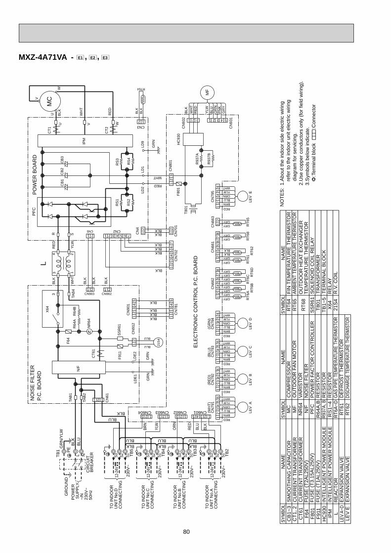
80
:Ter
min
al b
lock
:C
onne
ctor
3.S
ymbo
ls b
elow
indi
cate
.2.
Use
cop
per c
ondu
ctor
s on
ly (f
or fi
eld
wiri
ng).
dia
gram
for s
ervi
cing
. r
efer
to th
e in
door
uni
t ele
ctric
wiri
ng1.
Abo
ut th
e in
door
sid
e el
ectri
c w
iring
NO
TES
:SY
MBO
LN
AM
ESY
MBO
LN
AM
E
CU
RR
EN
T TR
AN
SFO
RM
ER
FUS
E (T
1AL2
50V
)FU
SE
(T3.
15A
L250
V)
LEV
A~D
EX
PAN
SIO
N V
ALV
EL
RE
AC
TOR
IPM
INTE
LLIG
EN
T P
OW
ER
MO
DU
LE
CT6
1C
T1, 2
CU
RR
EN
T TR
AN
SFO
RM
ER
HC
930
INTE
LLIG
EN
T P
OW
ER
MO
DU
LEF9
11F8
01F6
4FU
SE
(T2A
L250
V)
SM
OO
THIN
G C
APA
CIT
OR
CB
1~3
OU
TDO
OR
FA
N M
OTO
R
PO
WE
R F
AC
TOR
CO
NTR
OLL
ER
NO
ISE
FIL
TER
RT6
1D
EFR
OS
T TH
ER
MIS
TOR
RT6A
~DGA
S PI
PE T
EMPE
RATU
RE T
HERM
ISTO
RR
S1~
4R
ES
ISTO
RR9
37A,
BR
ES
ISTO
R
MF
MC
CO
MP
RE
SS
OR
R64
A,B
RE
SIS
TOR
PFCN/F
NR
64VA
RIS
TOR
EX
PAN
SIO
N V
ALV
ELE
V E
AMBI
ENT
TEM
PERA
TURE
THE
RMIS
TOR
SO
LEN
OID
CO
IL R
ELA
Y
21S
4R
.V. C
OIL
X64
RE
LAY
TB1~
5TE
RM
INA
L B
LOC
K
RT6
5R
T64
FIN
TE
MP
ER
ATU
RE
TH
ER
MIS
TOR
T801
TRA
NS
FOR
ME
RS
SR
61
RT6
8O
UTD
OO
R H
EAT
EX
CH
AN
GE
R
TEM
PE
RAT
UR
E T
HE
RM
ISTO
R
DISC
HARG
E TE
MPER
ATUR
E TH
ERMI
STOR
RT6
2
NA
ME
SYM
BOL
R64
B
21
(GR
N)
(BLU
)(R
ED
)(W
HT)
3
WHT
RED
LD9
GR
N
TAB
1
TAB
2
CN6013 2 1
CN6023 21
CN6043 2 1 23
CN6031 LE
VA
REDBRNBLUORNYLWWHT
CN
791
14
32
56
CN
792
14
32
56
LEV
B
REDBRNBLUORNYLWWHT
14
32
56
CN
793
LEV
WHTYLWORNBLUBRNRED
C
14
32
56
CN
794
LEV
WHTYLWORNBLUBRNRED
D
CN
663
12
RT6
DR
T6C
RT6
BR
T6A
GRYGRYGRYGRYGRYGRY
GRYGRY
23
45
61
78
CN
662
RT6
2
GRYGRY R
T61
76
54
32
18
CN
661
E
REDBRNBLUORNYLWWHT
LEV
CN
795
65
23
41
BLU
21S
4
BLU
54321321
MF
CN
931
CN
932
GR
NG
RN
LDE
2LD
E1
21CN5
765CN2
2 3 41
21CN
4LD
2LD
1
WH
T
RE
D
W
MCV
U BLK
WVU CN312
BLK
BLK
RT64
HC
930
BLK
BLKBLKBLK
BLKBLK
BLK
BLK
BLK
BLK
WH
TR
ED
YLW
BLU
OR
NP
NK
GR
Y
BLKBLK
GRYGRY
T801
R93
7B
R93
7A
RS
4
RS
3
RS
2
RS
1
IPM
CB
3C
B2
CB
1
PFC
NR
64C
T61
SS
R61
F911
N
21CN902
CN
912
CN
901
21CN903
N/F
CT2
CT1
54
32
1
BLK
BLKBLKBLK
TAB
4
X64
F64
R64
A
L
YLW
RE
DB
LK WH
T
R S
4 213
CN
801
32
12
1C
N70
16
71
23
45
CN
702
54
32
1C
N78
1F8
01
45
GRYGRY
RT6
5
321
CN
61
RT6
8
PE
TO IN
DO
OR
UN
IT N
o.D
CO
NN
EC
TIN
G
BR
EA
KE
R
GR
N/Y
LW
CIR
CU
IT
PO
WE
R S
UP
PLY
~/N
230V
~50
Hz
TB1
L N S2S3 S1 S3 S2 S1 S3 S2 S1 S3 S2 S1
GR
OU
ND
BLU
BLK BLK BLK
BLK
BLU BLU BLU
BLU
YLW
ORN
RED
BRN
BLK
12-2
4V
230V
~
12-2
4V
230V
~
12-2
4V
230V
~
12-2
4V
230V
~
BLU
BLK
TO IN
DO
OR
UN
IT N
o.C
CO
NN
EC
TIN
G
TO IN
DO
OR
UN
IT N
o.B
CO
NN
EC
TIN
G
TO IN
DO
OR
UN
IT N
o.A
CO
NN
EC
TIN
G
TB5
TB4
TB3
TB2
ELE
CTR
ON
IC C
ON
TRO
L P.
C. B
OA
RD
NO
ISE
FIL
TER
P.C
. BO
AR
DP
OW
ER
BO
AR
D
MXZ-4A71VA - E1 , E2 , E3

81
:Ter
min
al b
lock
:C
onne
ctor
3.S
ymbo
ls b
elow
indi
cate
.2.
Use
cop
per c
ondu
ctor
s on
ly (f
or fi
eld
wiri
ng).
dia
gram
for s
ervi
cing
. r
efer
to th
e in
door
uni
t ele
ctric
wiri
ng1.
Abo
ut th
e in
door
sid
e el
ectri
c w
iring
NO
TES
:SY
MBO
LN
AM
ESY
MBO
LN
AM
E
CU
RR
EN
T TR
AN
SFO
RM
ER
FUS
E (T
1AL2
50V
)FU
SE
(T3.
15A
L250
V)
LEV
A~D
EX
PAN
SIO
N V
ALV
EL
RE
AC
TOR
IPM
INTE
LLIG
EN
T P
OW
ER
MO
DU
LE
CT6
1C
T1, 2
CU
RR
EN
T TR
AN
SFO
RM
ER
HC
930
INTE
LLIG
EN
T P
OW
ER
MO
DU
LEF9
11F8
01F6
4FU
SE
(T2A
L250
V)
SM
OO
THIN
G C
APA
CIT
OR
CB
1~3
OU
TDO
OR
FA
N M
OTO
R
PO
WE
R F
AC
TOR
CO
NTR
OLL
ER
NO
ISE
FIL
TER
RT6
1D
EFR
OS
T TH
ER
MIS
TOR
RS
1~4
RE
SIS
TOR
R937
A, B
RE
SIS
TOR
MF
MC
CO
MP
RE
SS
OR
R64
A,B
RE
SIS
TOR
PFCN/F
NR
64VA
RIS
TOR
EX
PAN
SIO
N V
ALV
ELE
V E
AMBI
ENT
TEM
PERA
TURE
THE
RMIS
TOR
SO
LEN
OID
CO
IL R
ELA
Y
21S
4R
.V. C
OIL
X64
RE
LAY
TB1~
5TE
RM
INA
L B
LOC
K
RT6
5
RT6
4FI
N T
EM
PE
RAT
UR
E T
HE
RM
ISTO
R
T801
TRA
NS
FOR
ME
RS
SR
61
RT6
8O
UTD
OO
R H
EAT
EX
CH
AN
GE
R
TEM
PE
RAT
UR
E T
HE
RM
ISTO
R
DISC
HARG
E TE
MPER
ATUR
E TH
ERMI
STOR
RT6
2
NA
ME
SYM
BOL
MXZ-4A71VA - E4

82
NO
TES
: 1. A
bout
the
indo
or s
ide
elec
tric
wiri
ng re
fer t
o
th
e in
door
uni
t ele
ctric
wiri
ng d
iagr
am fo
r ser
vici
ng.
2.
Use
cop
per c
ondu
ctor
s on
ly (F
or fi
eld
wiri
ng).
3.
Sym
bols
bel
ow in
dica
te.
: Te
rmin
al b
lock
:
Con
nect
or
OUTD
OOR
HEAT
EXC
HANG
ER TE
MP.TH
ERMI
STOR
R937
A,B
RE
SIS
TOR
RT6
8C
OM
PR
ES
SO
RFU
SE
(T6.
3AL2
50V
)F6
5M
C21
S4
REVE
RSIN
G VA
LVE
SOLE
NOID
COI
LA
MB
IEN
T TE
MP.
THE
RM
ISTO
RPT
C64,
65C
IRC
UIT
PR
OTE
CTI
ON
RT6
5FU
SE
(T2A
L250
V)
EX
PAN
SIO
N V
ALV
ELE
V E
F64
X64
RE
LAY
FIN
TE
MP.
THE
RM
ISTO
RPO
WER
FACT
OR C
ONTR
OLLE
RR
T64
PFC
EX
PAN
SIO
N V
ALV
E
FUSE
(T3.
15AL
250V
)
LEV
A~D
F801
TER
MIN
AL
BLO
CK
TB1~
5D
ISC
HA
RG
E T
EM
P.TH
ER
MIS
TOR
RT6
2N
OIS
E F
ILTE
RN
/FR
EA
CTO
RL
CT6
1CU
RREN
T TRA
NSFO
RMER
RT6
1D
EFR
OS
T TH
ER
MIS
TOR
NR
64VA
RIS
TOR
IPM
INTE
LLIG
ENT
POW
ER M
ODUL
ECU
RREN
T TRA
NSFO
RMER
CT1
,2TR
AN
SFO
RM
ER
T801
SS
R61
SO
LEN
OID
CO
IL R
ELA
YR
S1~
4R
ES
ISTO
RFA
N M
OTO
RM
FH
C93
0IN
TELL
IGEN
T PO
WER
MOD
ULE
SMOO
THIN
G CA
PACI
TOR
CB
1~3
NA
ME
NA
ME
NA
ME
NA
ME
NA
ME
SYM
BOL
SYM
BOL
SYM
BOL
SYM
BOL
SYM
BOL
PTC6
5
PTC6
4
LED3
RT65
66
66
LEV A
CN79
4(BL
U)
LEV DM
(RED)
CN79
3
LEV B
CN79
1 6
MM
M(WHT
)(G
RN)
CN79
2
LEV C
RT62
RT68
RT61
CN66
1
18
CN66
3 21
CT2
CN5
1
2
S3CN
931
RS1
CN78
1
CN60
33
3
CN70
2
S2CN
795
1
CN60
2
RS2
CN2
S
1
CN70
1
1
S1
CB3
CN60
1
1
RS4
2
3
5
R937
A
1R
1
2
+
1
CN80
1
U
CN3
LD9
RS3
3
7
R937
B
3~
F801
V
CB2
1
1
CN4
4
IPM
LED2
1
T801
MS
PFC
W
2
1
8
+
5
LED1
HC93
0
1
LD2
CT1
3
CB1
1
2
CN60
4
CN93
2
3+
5
7LD
1
1
LDE1
CN90
31TA
B4
23
N/F
NR64
1
X64
U
5
1
CN61
CN90
12CN90
2
F64
13
N/F
CT61
SSR6
1
12
CN91
2
POW
ER S
UPPL
Y~/N
230V
50Hz
BRN
YLW
ORN
RED
BLU
BLK
RED
BLU
BLK
BLU
BLK
12-24
V
230V
~TB2
S1
ORN
S3BL
K
12-24
V
230V
~
S2BL
U
S1
YLW
S3BL
K
12-24
V
230V
~
S2BL
U
S1
BRN
S3BL
K
12-24
V
230V
~
S2BL
U
TB3
TB4
TB5
BLK
WHT
RED
YLW
BLK
BLK
BLK
BLK
BLK
BLK
BLK
BLKBLKBLK
BLK
BLK
L
BLK
BLK
RED
WHT
21S4
GRN
TO IN
DOOR
UNIT
No.A
CONN
ECTI
NG
TO IN
DOOR
UNIT
No.B
CONN
ECTI
NG
TO IN
DOOR
UNIT
No.C
CONN
ECTI
NG
TO IN
DOOR
UNIT
No.D
CONN
ECTI
NG
GRY
PNK
ORN
BLU
YLW
RED
WHT
BLK
RT64
M LEV E
MC3~M
SV
BLK
WHT
RED
U W
MF
BLU
BLK
NL
BREA
KER
CIRCU
ITTB1
PE
TAB2
TAB1
F65
GRN/Y
LW
NOISE
FILT
ER P.
C.BOA
RDPO
WER B
OARD
ELEC
TRON
IC CO
NTRO
L P.C.
BOAR
D
MXZ-4A71VA - E5 , E6

83
MXZ-4A71VA - E7
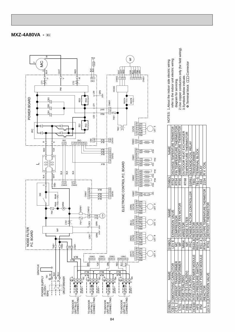
84
MXZ-4A80VA - E1
:Ter
min
al b
lock
:C
onne
ctor
3.S
ymbo
ls b
elow
indi
cate
.2.
Use
cop
per c
ondu
ctor
s on
ly (f
or fi
eld
wiri
ng).
dia
gram
for s
ervi
cing
. r
efer
to th
e in
door
uni
t ele
ctric
wiri
ng1.
Abo
ut th
e in
door
sid
e el
ectri
c w
iring
NO
TES
:SY
MBO
LN
AM
ESY
MBO
LN
AM
E
CU
RR
EN
T TR
AN
SFO
RM
ER
FUS
E (T
2AL2
50V
)
FUS
E (T
1AL2
50V
)
LEV
A~D
EX
PAN
SIO
N V
ALV
EL
RE
AC
TOR
IPM
INTE
LLIG
EN
T P
OW
ER
MO
DU
LEH
PS
HIG
H P
RE
SS
UR
E S
WIT
CH
CT6
1C
T1, 2
CU
RR
EN
T TR
AN
SFO
RM
ER
HC
930
INTE
LLIG
EN
T P
OW
ER
MO
DU
LE
F64
F911
F801
FUS
E (T
3.15
AL2
50V
)
SM
OO
THIN
G C
APA
CIT
OR
CB
1~3
OU
TDO
OR
FA
N M
OTO
R
PO
WE
R F
AC
TOR
CO
NTR
OLL
ER
NO
ISE
FIL
TER
RT6
1D
EFR
OS
T TH
ER
MIS
TOR
RT6A
~DGA
S PI
PE T
EMPE
RATU
RE T
HERM
ISTO
RR
S1~
4R
ES
ISTO
RR9
37A,
BR
ES
ISTO
R
MF
MC
CO
MP
RE
SS
OR
R64
A,B
RE
SIS
TOR
PFCN/F
NR
64VA
RIS
TOR
EX
PAN
SIO
N V
ALV
ELE
V E
AMBI
ENT
TEM
PERA
TURE
THE
RMIS
TOR
SO
LEN
OID
CO
IL R
ELA
Y
21S
4R
.V. C
OIL
X64
RE
LAY
TB1~
5TE
RM
INA
L B
LOC
K
RT6
5R
T64
FIN
TE
MP
ER
ATU
RE
TH
ER
MIS
TOR
T801
TRA
NS
FOR
ME
RS
SR
61
RT6
8O
UTD
OO
R H
EAT
EX
CH
AN
GE
R
TEM
PE
RAT
UR
E T
HE
RM
ISTO
R
DISC
HARG
E TE
MPER
ATUR
E TH
ERMI
STOR
RT6
2N
AM
ESY
MBO
L
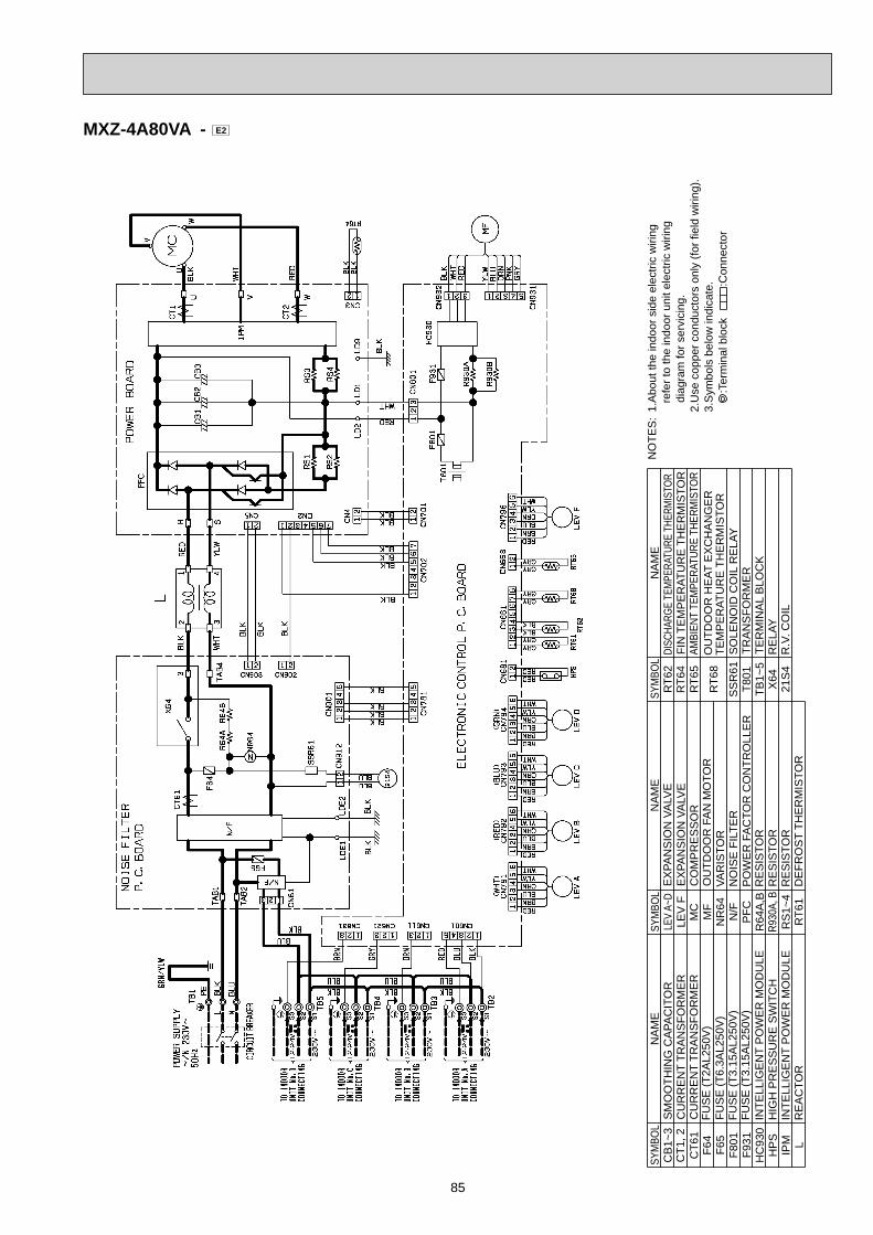
85
MXZ-4A80VA - E2
:Ter
min
al b
lock
:C
onne
ctor
3.S
ymbo
ls b
elow
indi
cate
.2.
Use
cop
per c
ondu
ctor
s on
ly (f
or fi
eld
wiri
ng).
dia
gram
for s
ervi
cing
. r
efer
to th
e in
door
uni
t ele
ctric
wiri
ng1.
Abo
ut th
e in
door
sid
e el
ectri
c w
iring
NO
TES
:SY
MBO
LN
AM
ESY
MBO
LN
AM
E
CU
RR
EN
T TR
AN
SFO
RM
ER
FUS
E (T
2AL2
50V
)
FUS
E (T
3.15
AL2
50V
)
LEV
A~D
EX
PAN
SIO
N V
ALV
E
LR
EA
CTO
RIP
MIN
TELL
IGE
NT
PO
WE
R M
OD
ULE
HP
SH
IGH
PR
ES
SU
RE
SW
ITC
H
CT6
1C
T1, 2
CU
RR
EN
T TR
AN
SFO
RM
ER
HC
930
INTE
LLIG
EN
T P
OW
ER
MO
DU
LE
F64
F931
F801
FUS
E (T
3.15
AL2
50V
)
SM
OO
THIN
G C
APA
CIT
OR
CB
1~3
OU
TDO
OR
FA
N M
OTO
R
PO
WE
R F
AC
TOR
CO
NTR
OLL
ER
NO
ISE
FIL
TER
RT6
1D
EFR
OS
T TH
ER
MIS
TOR
RS
1~4
RE
SIS
TOR
R930
A, B
RE
SIS
TOR
MF
MC
CO
MP
RE
SS
OR
R64
A,B
RE
SIS
TOR
PFCN/F
NR
64VA
RIS
TOR
EX
PAN
SIO
N V
ALV
ELE
V F
AMBI
ENT
TEM
PERA
TURE
THE
RMIS
TOR
SO
LEN
OID
CO
IL R
ELA
Y
21S
4R
.V. C
OIL
X64
RE
LAY
TB1~
5TE
RM
INA
L B
LOC
K
RT6
5R
T64
FIN
TE
MP
ER
ATU
RE
TH
ER
MIS
TOR
T801
TRA
NS
FOR
ME
RS
SR
61
RT6
8O
UTD
OO
R H
EAT
EX
CH
AN
GE
R
TEM
PE
RAT
UR
E T
HE
RM
ISTO
R
DISC
HARG
E TE
MPER
ATUR
E TH
ERMI
STOR
RT6
2N
AM
ESY
MBO
L
F65
FUS
E (T
6.3A
L250
V)
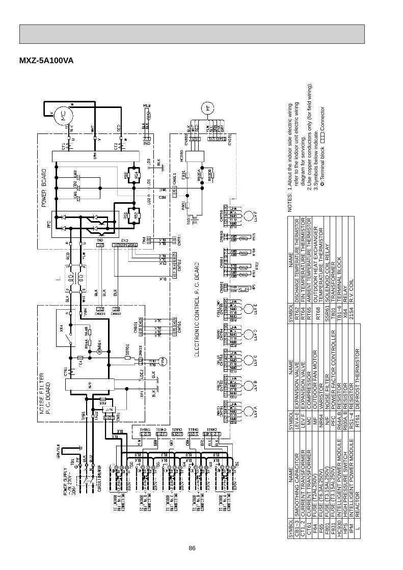
86
MXZ-5A100VA
:Ter
min
al b
lock
:C
onne
ctor
3.S
ymbo
ls b
elow
indi
cate
.2.
Use
cop
per c
ondu
ctor
s on
ly (f
or fi
eld
wiri
ng).
dia
gram
for s
ervi
cing
. r
efer
to th
e in
door
uni
t ele
ctric
wiri
ng1.
Abo
ut th
e in
door
sid
e el
ectri
c w
iring
NO
TES
:SY
MBO
LN
AM
ESY
MBO
LN
AM
E
CU
RR
EN
T TR
AN
SFO
RM
ER
FUS
E (T
2AL2
50V
)
FUS
E (T
3.15
AL2
50V
)
LEV
A~E
EX
PAN
SIO
N V
ALV
E
LR
EA
CTO
RIP
MIN
TELL
IGE
NT
PO
WE
R M
OD
ULE
HP
SH
IGH
PR
ES
SU
RE
SW
ITC
H
CT6
1C
T1, 2
CU
RR
EN
T TR
AN
SFO
RM
ER
HC
930
INTE
LLIG
EN
T P
OW
ER
MO
DU
LE
F64
F931
F801
FUS
E (T
3.15
AL2
50V
)
SM
OO
THIN
G C
APA
CIT
OR
CB
1~3
OU
TDO
OR
FA
N M
OTO
R
PO
WE
R F
AC
TOR
CO
NTR
OLL
ER
NO
ISE
FIL
TER
RT6
1D
EFR
OS
T TH
ER
MIS
TOR
RS
1~4
RE
SIS
TOR
R930
A, B
RE
SIS
TOR
MF
MC
CO
MP
RE
SS
OR
R64
A,B
RE
SIS
TOR
PFCN/F
NR
64VA
RIS
TOR
EX
PAN
SIO
N V
ALV
ELE
V F
AMBI
ENT
TEM
PERA
TURE
THE
RMIS
TOR
SO
LEN
OID
CO
IL R
ELA
Y
21S
4R
.V. C
OIL
X64
RE
LAY
TB1~
6TE
RM
INA
L B
LOC
K
RT6
5R
T64
FIN
TE
MP
ER
ATU
RE
TH
ER
MIS
TOR
T801
TRA
NS
FOR
ME
RS
SR
61
RT6
8O
UTD
OO
R H
EAT
EX
CH
AN
GE
R
TEM
PE
RAT
UR
E T
HE
RM
ISTO
R
DISC
HARG
E TE
MPER
ATUR
E TH
ERMI
STOR
RT6
2N
AM
ESY
MBO
L
F65
FUS
E (T
6.3A
L250
V)
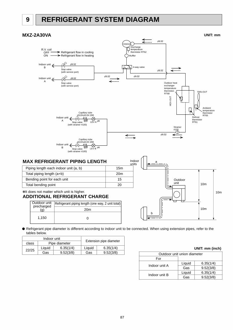
87
a
b
Outdoorunit
Indoorunits
10m
10m
10m
Refrigerant piping length (one way, 2 unit total)Outdoor unit precharged
(g) 20m
01,150
REFRIGERANT SYSTEM DIAGRAM9
Stop valve(with strainer #100)
LEV A
LEV B
Compressor
DefrostthermistorRT61
Muffler
4-way valveIndoor unit
B
Indoor unitA
Indoor unitA
Indoor unitB
Capillary tube
Capillary tube
Strainer#100
Stop valve(with strainer #100)
R.V. coil OFF ON
Refrigerant flow in coolingRefrigerant flow in heating
AmbienttemperaturethermistorRT65
Outdoor heatexchangertemperaturethermistorRT68
FAN-OUT
HE
X-O
UT
Dischargetemperaturethermistor RT62
Stop valve(with service port)
Stop valve(with service port)
Refrigerant pipe diameter is different according to indoor unit to be connected. When using extension pipes, refer to the tables below.
UNIT: mm (inch)
Piping length each indoor unit (a, b) 15m Total piping length (a+b) 20m Bending point for each unit 15 Total bending point 20
It does not matter which unit is higher.ADDITIONAL REFRIGERANT CHARGE
UNIT: mmMXZ-2A30VA
MAX REFRIGERANT PIPING LENGTH
Indoor unit Extension pipe diameterclass Pipe diameter
22/25 Liquid 6.35(1/4) Liquid 6.35(1/4)Gas 9.52(3/8) Gas 9.52(3/8) Outdoor unit union diameter
For
Indoor unit A Liquid 6.35(1/4)Gas 9.52(3/8)
Indoor unit B Liquid 6.35(1/4)Gas 9.52(3/8)

88
Stop valve(with strainer #100)
LEV A
LEV B
Compressor
DefrostthermistorRT61
Distributor
Muffler
4-way valveIndoor unit
B
Indoor unitA
Indoor unitA
Indoor unitB
Capillary tube
Capillary tube
Capillary tube
Strainer#100
Stop valve(with strainer #100)
R.V. coil OFF ON
Refrigerant flow in coolingRefrigerant flow in heating
AmbienttemperaturethermistorRT65
Outdoor heatexchangertemperaturethermistorRT68 FAN-OUT
HE
X-O
UT
Dischargetemperaturethermistor RT62
Stop valve(with service port)
Stop valve(with service port)
Refrigerant pipe diameter is different according to indoor unit to be connected. When using extension pipes, refer to the tables below.
UNIT: mm (inch)
Piping length each indoor unit (a, b) 20m Total piping length (a+b) 30m Bending point for each unit 20 Total bending point 30
It does not matter which unit is higher.ADDITIONAL REFRIGERANT CHARGE
UNIT: mmMXZ-2A40VA - E1 MXZ-2A52VA
MAX REFRIGERANT PIPING LENGTH a
b
Outdoorunit
Indoorunits
15m
10m
15m
Refrigerant piping length (one way, 2 unit total)
Calculation : Xg = 20 g/m x (Refrigerant piping length(m) - 20)
Outdoor unit precharged
(g) 30m
200
20m
01,300
Indoor unit Extension pipe diameterclass Pipe diameter
22/25/35 Liquid 6.35(1/4) Liquid 6.35(1/4)Gas 9.52(3/8) Gas 9.52(3/8)
Outdoor unit union diameterFor
Indoor unit A Liquid 6.35(1/4)Gas 9.52(3/8)
Indoor unit B Liquid 6.35(1/4)Gas 9.52(3/8)
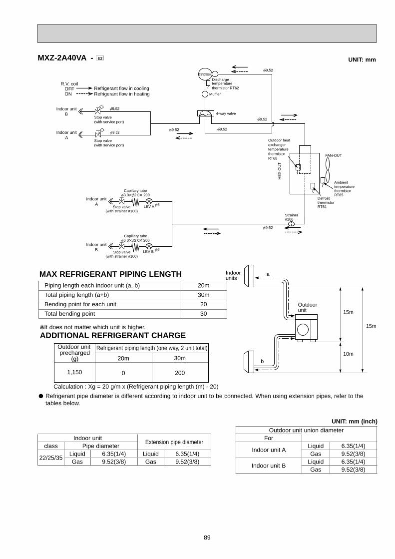
89
Stop valve(with strainer #100)
LEV A
LEV B
Compressor
Muffler
DefrostthermistorRT61
AmbienttemperaturethermistorRT65
Outdoor heatexchangertemperaturethermistorRT68
FAN-OUT
HE
X-O
UT
4-way valveIndoor unit
B
Indoor unitA
Indoor unitA
Indoor unitB
Capillary tube
Capillary tube
Strainer#100
Stop valve(with strainer #100)
R.V. coil OFF ON
Refrigerant flow in coolingRefrigerant flow in heating
Dischargetemperaturethermistor RT62
Stop valve(with service port)
Stop valve(with service port)
Refrigerant pipe diameter is different according to indoor unit to be connected. When using extension pipes, refer to the tables below.
UNIT: mm (inch)
Piping length each indoor unit (a, b) 20m Total piping length (a+b) 30m Bending point for each unit 20 Total bending point 30
It does not matter which unit is higher.ADDITIONAL REFRIGERANT CHARGE
UNIT: mmMXZ-2A40VA - E2
MAX REFRIGERANT PIPING LENGTH a
b
Outdoorunit
Indoorunits
15m
10m
15m
Refrigerant piping length (one way, 2 unit total)
Calculation : Xg = 20 g/m x (Refrigerant piping length (m) - 20)
Outdoor unit precharged
(g) 30m
200
20m
01,150
Indoor unit Extension pipe diameterclass Pipe diameter
22/25/35 Liquid 6.35(1/4) Liquid 6.35(1/4)Gas 9.52(3/8) Gas 9.52(3/8)
Outdoor unit union diameterFor
Indoor unit A Liquid 6.35(1/4)Gas 9.52(3/8)
Indoor unit B Liquid 6.35(1/4)Gas 9.52(3/8)
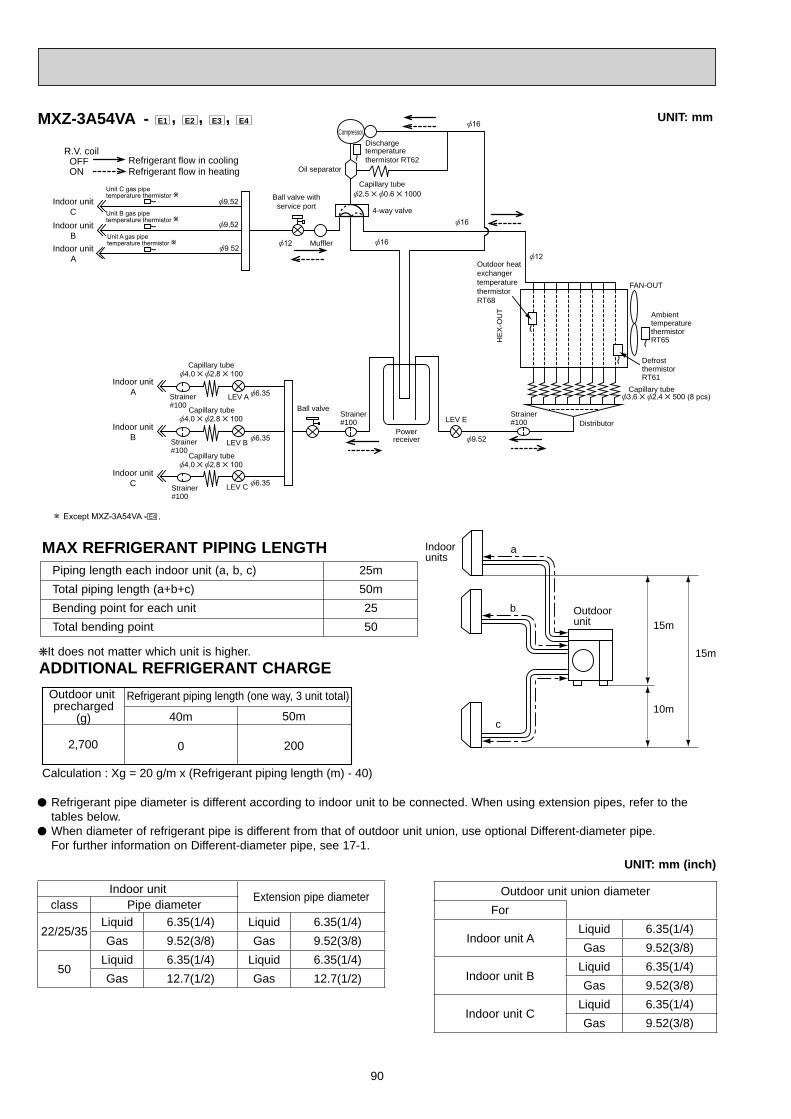
90
a
b
c
Outdoorunit
Indoorunits
15m
10m
15m
Refrigerant piping length (one way, 3 unit total)
Calculation : Xg = 20 g/m x (Refrigerant piping length (m) - 40)
Outdoor unit precharged
(g) 50m
200
40m
02,700
Ball valve withservice port
Ball valveStrainer#100
Powerreceiver
LEV A
LEV B
LEV C
Oil separator
Compressor
DefrostthermistorRT61
Distributor
Muffler
4-way valve
LEV E
Indoor unitC
Indoor unitB
Indoor unitA
Indoor unitA
Indoor unitB
Indoor unitC
Capillary tube
Capillary tube
Capillary tube
Capillary tube
Capillary tube
Dischargetemperaturethermistor RT62
Strainer#100
Strainer#100
Strainer#100
R.V. coil OFF ON
Refrigerant flow in coolingRefrigerant flow in heating
AmbienttemperaturethermistorRT65
Outdoor heatexchangertemperaturethermistorRT68
FAN-OUT
HE
X-O
UT
Strainer#100
Refrigerant pipe diameter is different according to indoor unit to be connected. When using extension pipes, refer to the tables below.
When diameter of refrigerant pipe is different from that of outdoor unit union, use optional Different-diameter pipe. For further information on Different-diameter pipe, see 17-1.
UNIT: mm (inch)
Piping length each indoor unit (a, b, c) 25m Total piping length (a+b+c) 50m Bending point for each unit 25 Total bending point 50
It does not matter which unit is higher.ADDITIONAL REFRIGERANT CHARGE
UNIT: mmMXZ-3A54VA - E1 , E2 , E3 , E4
MAX REFRIGERANT PIPING LENGTH
Indoor unit Extension pipe diameterclass Pipe diameter
22/25/35Liquid 6.35(1/4) Liquid 6.35(1/4)Gas 9.52(3/8) Gas 9.52(3/8)
50Liquid 6.35(1/4) Liquid 6.35(1/4)Gas 12.7(1/2) Gas 12.7(1/2)
Outdoor unit union diameterFor
Indoor unit ALiquid 6.35(1/4)Gas 9.52(3/8)
Indoor unit BLiquid 6.35(1/4)Gas 9.52(3/8)
Indoor unit CLiquid 6.35(1/4)Gas 9.52(3/8)

91
a
b
c
Outdoorunit
Indoorunits
15m
10m
15m
Refrigerant piping length (one way, 3 unit total)
Calculation : Xg = 20 g/m x (Refrigerant piping length (m) - 40)
Outdoor unit precharged
(g) 50m
200
40m
02,700
Strainer#100
Powerreceiver
LEV A
LEV B
LEV C
Oil separator
Compressor
DefrostthermistorRT61
Distributor
Muffler
4-way valve
LEV E
Indoor unitC
Indoor unitB
Indoor unitA
Indoor unitA
Indoor unitB
Indoor unitC
Capillary tube
Capillary tube
Capillary tube
Capillary tube
Capillary tube
Dischargetemperaturethermistor RT62
Strainer#100
Strainer#100
Strainer#100
R.V. coil OFF ON
Refrigerant flow in coolingRefrigerant flow in heating
AmbienttemperaturethermistorRT65
Outdoor heatexchangertemperaturethermistorRT68
FAN-OUT
HE
X-O
UT
Strainer#100
Stop valve withservice port
Stop valve
Refrigerant pipe diameter is different according to indoor unit to be connected. When using extension pipes, refer to the tables below.
When diameter of refrigerant pipe is different from that of outdoor unit union, use optional Different-diameter pipe. For further information on Different-diameter pipe, see 17-1.
UNIT: mm (inch)
Piping length each indoor unit (a, b, c) 25m Total piping length (a+b+c) 50m Bending point for each unit 25 Total bending point 50
It does not matter which unit is higher.ADDITIONAL REFRIGERANT CHARGE
MAX REFRIGERANT PIPING LENGTH
UNIT: mmMXZ-3A54VA - E5 , E6 , E7
Indoor unit Extension pipe diameterclass Pipe diameter
22/25/35/42Liquid 6.35(1/4) Liquid 6.35(1/4)Gas 9.52(3/8) Gas 9.52(3/8)
50Liquid 6.35(1/4) Liquid 6.35(1/4)Gas 12.7(1/2) Gas 12.7(1/2)
Outdoor unit union diameterFor
Indoor unit ALiquid 6.35(1/4)Gas 9.52(3/8)
Indoor unit BLiquid 6.35(1/4)Gas 9.52(3/8)
Indoor unit CLiquid 6.35(1/4)Gas 9.52(3/8)
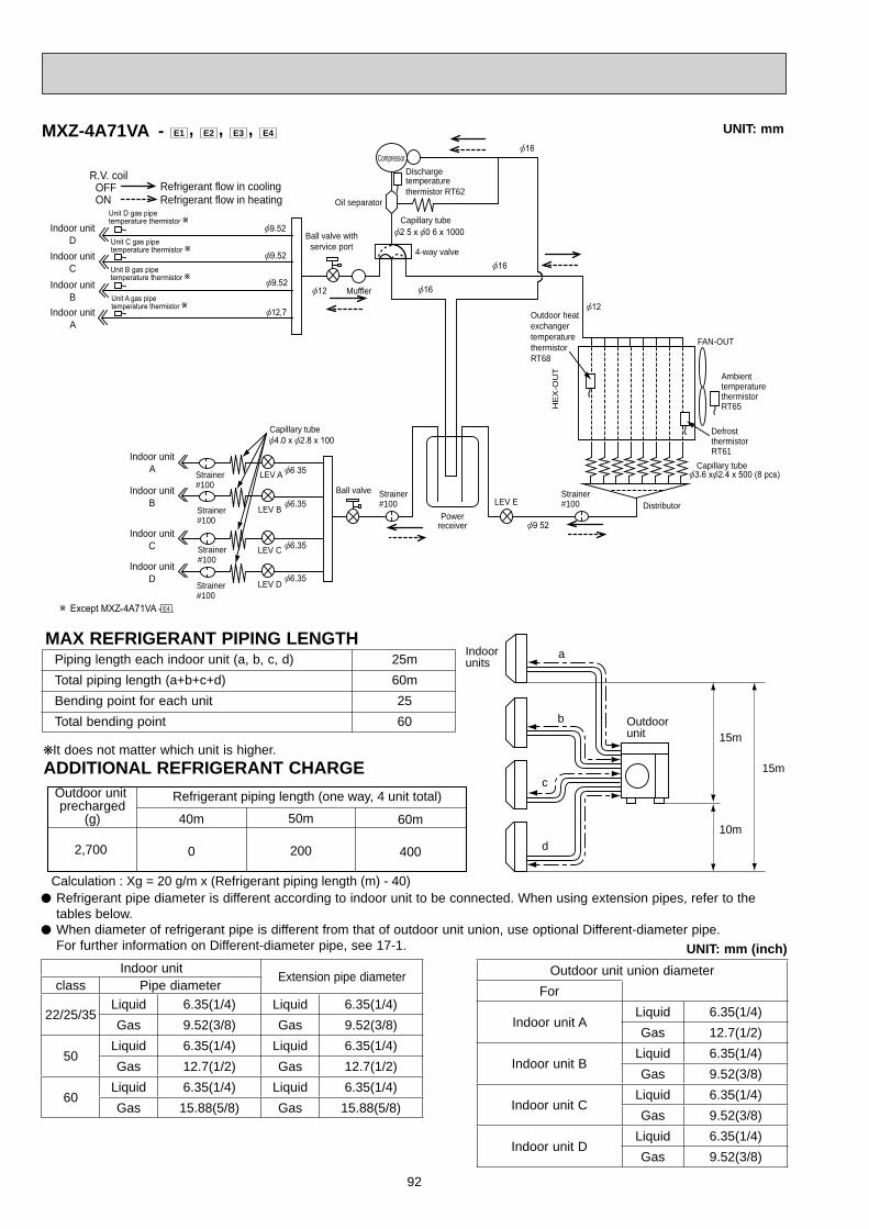
92
Indoor unitD Ball valve with
service port
Ball valve
Powerreceiver
LEV A
LEV B
LEV C
LEV D
Oil separator
Compressor
Muffler
4-way valve
LEV E
Indoor unitC
Indoor unitB
Indoor unitA
Indoor unitA
Indoor unitB
Indoor unitC
Indoor unitD
Capillary tube
Capillary tube
Dischargetemperaturethermistor RT62
Strainer#100
Strainer#100
Strainer#100
Strainer#100
Strainer#100
R.V. coil OFF ON
Refrigerant flow in coolingRefrigerant flow in heating
Distributor
HE
X-O
UT
Outdoor heatexchangertemperaturethermistorRT68
DefrostthermistorRT61
Capillary tube
AmbienttemperaturethermistorRT65
FAN-OUT
Strainer#100
a
b
c
d
Outdoorunit
Indoorunits
15m
10m
15m
Refrigerant piping length (one way, 4 unit total)
Calculation : Xg = 20 g/m x (Refrigerant piping length (m) - 40)
Outdoor unit precharged
(g) 50m
200
40m
02,700
60m
400
UNIT: mm
Refrigerant pipe diameter is different according to indoor unit to be connected. When using extension pipes, refer to the tables below.
When diameter of refrigerant pipe is different from that of outdoor unit union, use optional Different-diameter pipe. For further information on Different-diameter pipe, see 17-1. UNIT: mm (inch)
Piping length each indoor unit (a, b, c, d) 25m Total piping length (a+b+c+d) 60m Bending point for each unit 25 Total bending point 60
It does not matter which unit is higher.ADDITIONAL REFRIGERANT CHARGE
MXZ-4A71VA - E1 , E2 , E3 , E4
MAX REFRIGERANT PIPING LENGTH
Indoor unit Extension pipe diameterclass Pipe diameter
22/25/35Liquid 6.35(1/4) Liquid 6.35(1/4)Gas 9.52(3/8) Gas 9.52(3/8)
50Liquid 6.35(1/4) Liquid 6.35(1/4)Gas 12.7(1/2) Gas 12.7(1/2)
60Liquid 6.35(1/4) Liquid 6.35(1/4)Gas 15.88(5/8) Gas 15.88(5/8)
Outdoor unit union diameterFor
Indoor unit ALiquid 6.35(1/4)Gas 12.7(1/2)
Indoor unit BLiquid 6.35(1/4)Gas 9.52(3/8)
Indoor unit CLiquid 6.35(1/4)Gas 9.52(3/8)
Indoor unit DLiquid 6.35(1/4)Gas 9.52(3/8)
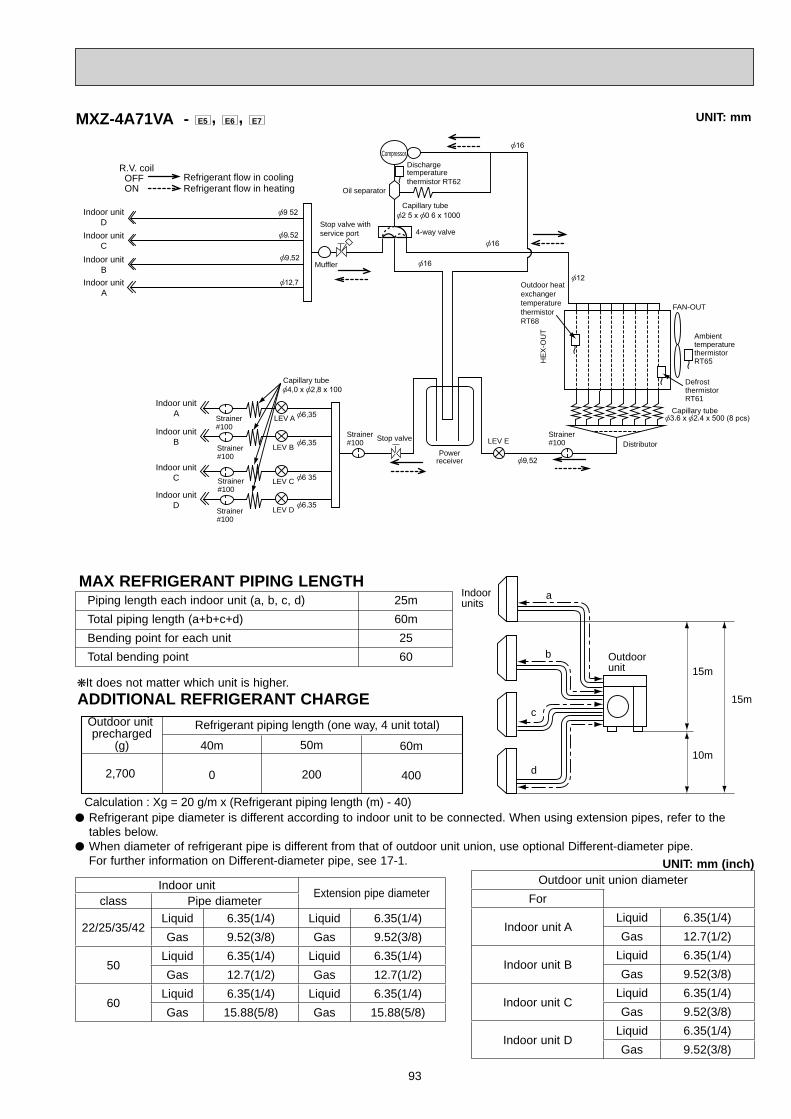
93
a
b
c
d
Outdoorunit
Indoorunits
15m
10m
15m
Refrigerant piping length (one way, 4 unit total)
Calculation : Xg = 20 g/m x (Refrigerant piping length (m) - 40)
Outdoor unit precharged
(g) 50m
200
40m
02,700
60m
400
Indoor unitD
Powerreceiver
LEV A
LEV B
LEV C
LEV D
Oil separator
Compressor
Muffler
4-way valve
LEV E
Indoor unitC
Indoor unitB
Indoor unitA
Indoor unitA
Indoor unitB
Indoor unitC
Indoor unitD
Capillary tube
Capillary tube
Dischargetemperaturethermistor RT62
Strainer#100
Strainer#100
Strainer#100
Strainer#100
Strainer#100
R.V. coil OFF ON
Refrigerant flow in coolingRefrigerant flow in heating
Distributor
HE
X-O
UT
Outdoor heatexchangertemperaturethermistorRT68
DefrostthermistorRT61
Capillary tube
AmbienttemperaturethermistorRT65
FAN-OUT
Strainer#100
Stop valve with service port
Stop valve
UNIT: mm
Refrigerant pipe diameter is different according to indoor unit to be connected. When using extension pipes, refer to the tables below.
When diameter of refrigerant pipe is different from that of outdoor unit union, use optional Different-diameter pipe. For further information on Different-diameter pipe, see 17-1. UNIT: mm (inch)
Piping length each indoor unit (a, b, c, d) 25m Total piping length (a+b+c+d) 60m Bending point for each unit 25 Total bending point 60
It does not matter which unit is higher.ADDITIONAL REFRIGERANT CHARGE
MXZ-4A71VA - E5 , E6 , E7
MAX REFRIGERANT PIPING LENGTH
Indoor unit Extension pipe diameterclass Pipe diameter
22/25/35/42Liquid 6.35(1/4) Liquid 6.35(1/4)Gas 9.52(3/8) Gas 9.52(3/8)
50Liquid 6.35(1/4) Liquid 6.35(1/4)Gas 12.7(1/2) Gas 12.7(1/2)
60Liquid 6.35(1/4) Liquid 6.35(1/4)Gas 15.88(5/8) Gas 15.88(5/8)
Outdoor unit union diameterFor
Indoor unit ALiquid 6.35(1/4)Gas 12.7(1/2)
Indoor unit BLiquid 6.35(1/4)Gas 9.52(3/8)
Indoor unit CLiquid 6.35(1/4)Gas 9.52(3/8)
Indoor unit DLiquid 6.35(1/4)Gas 9.52(3/8)
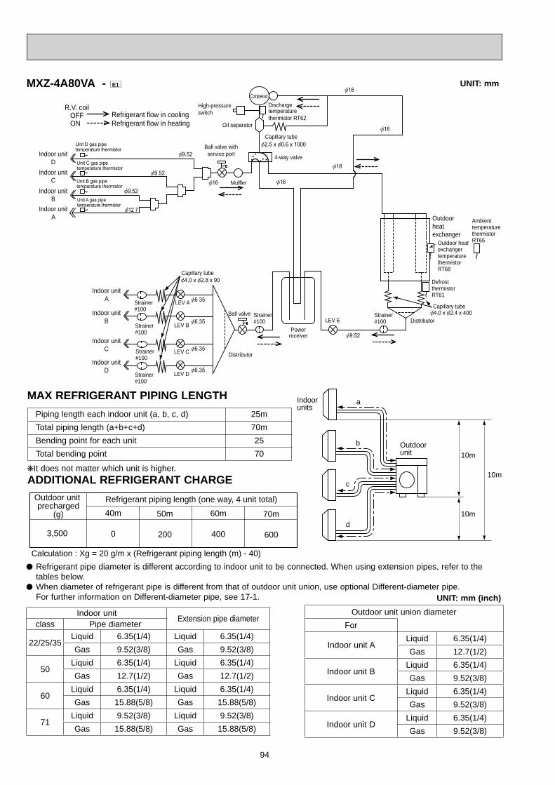
94
a
b
c
d
Outdoorunit
Indoorunits
10m
10m
10m
Refrigerant piping length (one way, 4 unit total)
Calculation : Xg = 20 g/m x (Refrigerant piping length (m) - 40)
Outdoor unit precharged
(g) 60m
400
40m
0
50m
2003,500
70m
600
Indoor unitD
Ball valve withservice port
Ball valve
Distributor
Powerreceiver
LEV A
LEV B
LEV C
LEV D
Oil separator
CompressorHigh-pressureswitch
Distributor
Muffler
4-way valve
LEV E
Outdoorheatexchanger
Indoor unitC
Indoor unitB
Indoor unitA
Indoor unitA
Indoor unitB
Indoor unitC
Indoor unitD
Capillary tube
Capillary tube
Capillary tube
Dischargetemperaturethermistor RT62
Strainer#100
Strainer#100
Strainer#100
Strainer#100
R.V. coil OFF ON
Refrigerant flow in coolingRefrigerant flow in heating
DefrostthermistorRT61
Outdoor heat exchangertemperaturethermistorRT68
AmbienttemperaturethermistorRT65
Strainer#100
Strainer#100
MXZ-4A80VA - E1 UNIT: mm
UNIT: mm (inch)
It does not matter which unit is higher.ADDITIONAL REFRIGERANT CHARGE
MAX REFRIGERANT PIPING LENGTH
Refrigerant pipe diameter is different according to indoor unit to be connected. When using extension pipes, refer to the tables below.
When diameter of refrigerant pipe is different from that of outdoor unit union, use optional Different-diameter pipe. For further information on Different-diameter pipe, see 17-1.
Piping length each indoor unit (a, b, c, d) 25m Total piping length (a+b+c+d) 70m Bending point for each unit 25 Total bending point 70
Indoor unit Extension pipe diameterclass Pipe diameter
22/25/35Liquid 6.35(1/4) Liquid 6.35(1/4)Gas 9.52(3/8) Gas 9.52(3/8)
50Liquid 6.35(1/4) Liquid 6.35(1/4)Gas 12.7(1/2) Gas 12.7(1/2)
60Liquid 6.35(1/4) Liquid 6.35(1/4)Gas 15.88(5/8) Gas 15.88(5/8)
71Liquid 9.52(3/8) Liquid 9.52(3/8)Gas 15.88(5/8) Gas 15.88(5/8)
Outdoor unit union diameterFor
Indoor unit ALiquid 6.35(1/4)Gas 12.7(1/2)
Indoor unit BLiquid 6.35(1/4)Gas 9.52(3/8)
Indoor unit CLiquid 6.35(1/4)Gas 9.52(3/8)
Indoor unit DLiquid 6.35(1/4)Gas 9.52(3/8)
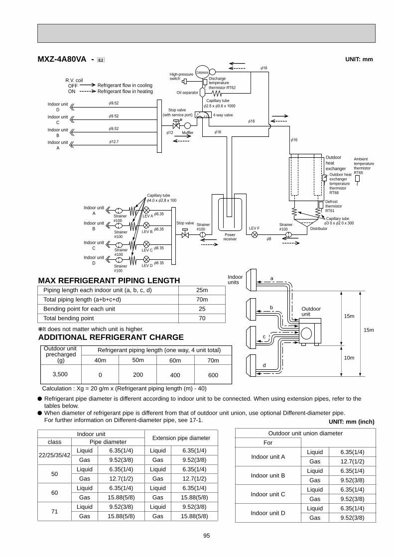
95
a
b
c
d
Outdoorunit
Indoorunits
15m
10m
15m
Refrigerant piping length (one way, 4 unit total)
Calculation : Xg = 20 g/m x (Refrigerant piping length (m) - 40)
Outdoor unit precharged
(g) 50m
200
40m
03,500
60m
400
70m
600
Indoor unitD Stop valve
(with service port)
Stop valve
Powerreceiver
LEV A
LEV B
LEV C
LEV D
Oil separator
Compressor
Muffler
4-way valve
LEV F
Indoor unitC
Indoor unitB
Indoor unitA
Indoor unitA
Indoor unitB
Indoor unitC
Indoor unitD
Capillary tube
Capillary tube
Dischargetemperaturethermistor RT62
High-pressureswitch
Strainer#100
Strainer#100
Strainer#100
Strainer#100
Strainer#100
R.V. coil OFF ON
Refrigerant flow in coolingRefrigerant flow in heating
Strainer#100 Distributor
Outdoorheatexchanger
Capillary tube
DefrostthermistorRT61
Outdoor heat exchangertemperaturethermistorRT68
AmbienttemperaturethermistorRT65
MXZ-4A80VA - E2 UNIT: mm
Refrigerant pipe diameter is different according to indoor unit to be connected. When using extension pipes, refer to the tables below.
When diameter of refrigerant pipe is different from that of outdoor unit union, use optional Different-diameter pipe. For further information on Different-diameter pipe, see 17-1. UNIT: mm (inch)
Piping length each indoor unit (a, b, c, d) 25m Total piping length (a+b+c+d) 70m Bending point for each unit 25 Total bending point 70
It does not matter which unit is higher.ADDITIONAL REFRIGERANT CHARGE
MAX REFRIGERANT PIPING LENGTH
Indoor unit Extension pipe diameterclass Pipe diameter
22/25/35/42Liquid 6.35(1/4) Liquid 6.35(1/4)Gas 9.52(3/8) Gas 9.52(3/8)
50Liquid 6.35(1/4) Liquid 6.35(1/4)Gas 12.7(1/2) Gas 12.7(1/2)
60Liquid 6.35(1/4) Liquid 6.35(1/4)Gas 15.88(5/8) Gas 15.88(5/8)
71Liquid 9.52(3/8) Liquid 9.52(3/8)Gas 15.88(5/8) Gas 15.88(5/8)
Outdoor unit union diameterFor
Indoor unit ALiquid 6.35(1/4)Gas 12.7(1/2)
Indoor unit BLiquid 6.35(1/4)Gas 9.52(3/8)
Indoor unit CLiquid 6.35(1/4)Gas 9.52(3/8)
Indoor unit DLiquid 6.35(1/4)Gas 9.52(3/8)
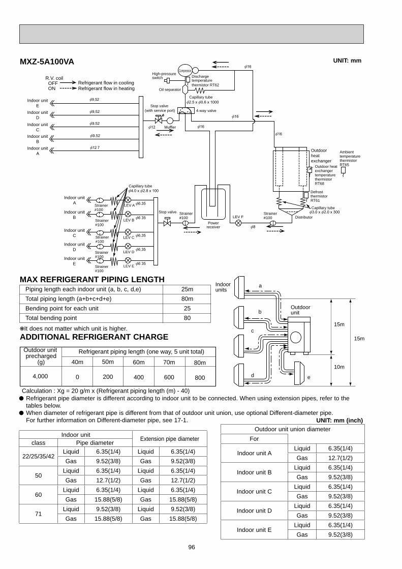
96
a
b
c
d
Outdoorunit
Indoorunits
15m
10m
15m
Refrigerant piping length (one way, 5 unit total)
Calculation : Xg = 20 g/m x (Refrigerant piping length (m) - 40)
e
Outdoor unit precharged
(g) 50m
200
40m
04,000
60m
400
70m
600
80m
800
Indoor unitE Stop valve
(with service port)
Stop valve
Powerreceiver
LEV A
LEV B
LEV C
LEV D
Oil separator
Compressor
Muffler
4-way valve
LEV F
Indoor unitD
Indoor unitC
Indoor unitB
Indoor unitA
Indoor unitB
Indoor unitC
Indoor unitD
Indoor unitA
Capillary tube
Capillary tube
Dischargetemperaturethermistor RT62
Strainer#100
Strainer#100
Strainer#100
Strainer#100
Strainer#100
LEV E
Indoor unitE
Strainer#100
R.V. coil OFF ON
Refrigerant flow in coolingRefrigerant flow in heating
Strainer#100 Distributor
Outdoorheatexchanger
Capillary tube
DefrostthermistorRT61
Outdoor heat exchangertemperaturethermistorRT68
AmbienttemperaturethermistorRT65
High-pressureswitch
MXZ-5A100VA UNIT: mm
Refrigerant pipe diameter is different according to indoor unit to be connected. When using extension pipes, refer to the tables below.
When diameter of refrigerant pipe is different from that of outdoor unit union, use optional Different-diameter pipe. For further information on Different-diameter pipe, see 17-1. UNIT: mm (inch)
Piping length each indoor unit (a, b, c, d,e) 25m Total piping length (a+b+c+d+e) 80m Bending point for each unit 25 Total bending point 80
It does not matter which unit is higher.ADDITIONAL REFRIGERANT CHARGE
MAX REFRIGERANT PIPING LENGTH
Indoor unit Extension pipe diameterclass Pipe diameter
22/25/35/42Liquid 6.35(1/4) Liquid 6.35(1/4)Gas 9.52(3/8) Gas 9.52(3/8)
50Liquid 6.35(1/4) Liquid 6.35(1/4)Gas 12.7(1/2) Gas 12.7(1/2)
60Liquid 6.35(1/4) Liquid 6.35(1/4)Gas 15.88(5/8) Gas 15.88(5/8)
71Liquid 9.52(3/8) Liquid 9.52(3/8)Gas 15.88(5/8) Gas 15.88(5/8)
Outdoor unit union diameterFor
Indoor unit ALiquid 6.35(1/4)Gas 12.7(1/2)
Indoor unit BLiquid 6.35(1/4)Gas 9.52(3/8)
Indoor unit CLiquid 6.35(1/4)Gas 9.52(3/8)
Indoor unit DLiquid 6.35(1/4)Gas 9.52(3/8)
Indoor unit ELiquid 6.35(1/4)Gas 9.52(3/8)

97
PERFORMANCE CURVES10
The standard specifications apply only to the operation of the air conditioner under normal conditions.Since operating conditions vary according to the areas where these units are installed, the following information has been pro-vided to clarify the operating characteristics of the air conditioner under the conditions indicated by the performance curve.(1) GUARANTEED VOLTAGE 198~264 V 50 Hz(2) AIR FLOW Air flow should be set at MAX.(3) MAIN READINGS (1) Indoor intake air wet-bulb temperature : °CWB (2) Indoor outlet air wet-bulb temperature : °CWB (3) Outdoor intake air dry-bulb temperature : °CDB (4) Total input: W (5) Indoor intake air dry-bulb temperature : °CDB (6) Outdoor intake air wet-bulb temperature : °CWB (7) Total input : W
Indoor air wet/dry-bulb temperature difference on the left side of the following chart shows the difference between the indoor intake air wet/dry-bulb temperature and the indoor outlet air wet/dry-bulb temperature for your reference at service.
How to measure the indoor air wet-bulb/dry-bulb temperature difference1. Attach at least 2 sets of wet and dry-bulb thermometers to the indoor air intake as shown in the figure, and at least 2 sets
of wet and dry-bulb thermometers to the indoor air outlet. The thermometers must be attached to the position where air speed is high.
2. Attach at least 2 sets of wet and dry-bulb thermometers to the outdoor air intake. Cover the thermometers to prevent direct rays of the sun.3. Check that the air filter is cleaned.4. Open windows and doors of room.5. Press the EMERGENCY OPERATION switch once (twice) to start the EMERGENCY COOL (HEAT) MODE.6. When system stabilizes after more than 15 minutes, measure temperature and take an average temperature.7. 10 minutes later, measure temperature again and check that the temperature does not change.
INDOOR UNIT OUTDOOR UNIT
}}
Cooling
Heating
Wet-and dry-bulbthermometersBACK VIEW
Wet and dry-bulbthermometersFRONT VIEW
MXZ-2A30VA MXZ-3A54VA MXZ-5A100VAMXZ-2A40VA MXZ-4A71VAMXZ-2A52VA MXZ-4A80VA

98
10-1. CAPACITY AND THE INPUT CURVES MXZ-2A30VAMXZ-2A40VAMXZ-2A52VA
22 c
lass
8.5
7.8
7.1
6.4
5.8
5.1
9.3
8.5
7.8
7.0
6.3
5.6
10.6
9.7
8.8
7.9
7.1
6.3
35 c
lass
25 c
lass
Indo
or a
ir W
et-b
ulb
tem
pera
ture
Outdoor intake air Dry-bulb temperature (°C) Outdoor intake air Dry-bulb temperature (°C)
Indoor intake air Wet-bulb temperature (°C) Indoor intake air Wet-bulb temperature (°C)
25.4
23.4
21.5
19.5
17.6
15.6
13.7
11.7
24.0
22.2
20.3
18.5
16.6
14.8
12.9
11.1
22 c
lass
25 c
lass
25.9
23.9
21.9
19.9
17.9
15.9
13.9
12.0
35 c
lass
Indo
or a
ir Dr
y-bu
lb te
mpe
ratu
re
Outdoor intake air Wet-bulb temperature (°C) Outdoor intake air Wet-bulb temperature (°C)
Indoor intake air Dry-bulb temperature (°C)
Indoor intake air Dry-bulb temperature (°C)
MXZ-3A54VAMXZ-4A71VA
22 c
lass
8.5
7.8
7.1
6.4
5.8
5.1
9.3
8.5
7.8
7.0
6.3
5.6
60 c
lass
10.6
9.7
8.8
7.9
7.1
6.3
13.1
11.9
10.8
9.7
8.7
7.7
9.5
8.7
8.0
7.2
6.5
5.7
13.7
12.4
11.3
10.1
9.0
8.0
50 c
lass
35 c
lass
42 c
lass
25 c
lass
Indo
or a
ir W
et-b
ulb
tem
pera
ture
Outdoor intake air Dry-bulb temperature (°C) Outdoor intake air Dry-bulb temperature (°C)
Indoor intake air Wet-bulb temperature (°C) Indoor intake air Wet-bulb temperature (°C)
25.4
23.4
21.5
19.5
17.6
15.6
13.7
11.7
24.0
22.2
20.3
18.5
16.6
14.8
12.9
11.1
22 c
lass
25 c
lass
60 c
lass
25.9
23.9
21.9
19.9
17.9
15.9
13.9
12.0
31.4
29.0
26.6
24.1
21.7
19.3
16.9
14.5
31.9
29.4
27.0
24.5
22.1
19.6
17.2
14.7
35 c
lass
50 c
lass
27.0
24.9
22.8
20.7
18.7
16.6
14.5
12.4
42 c
lass
Indo
or a
ir Dr
y-bu
lb te
mpe
ratu
re
Outdoor intake air Wet-bulb temperature (°C) Outdoor intake air Wet-bulb temperature (°C)
Indoor intake air Dry-bulb temperature (°C)
Indoor intake air Dry-bulb temperature (°C)
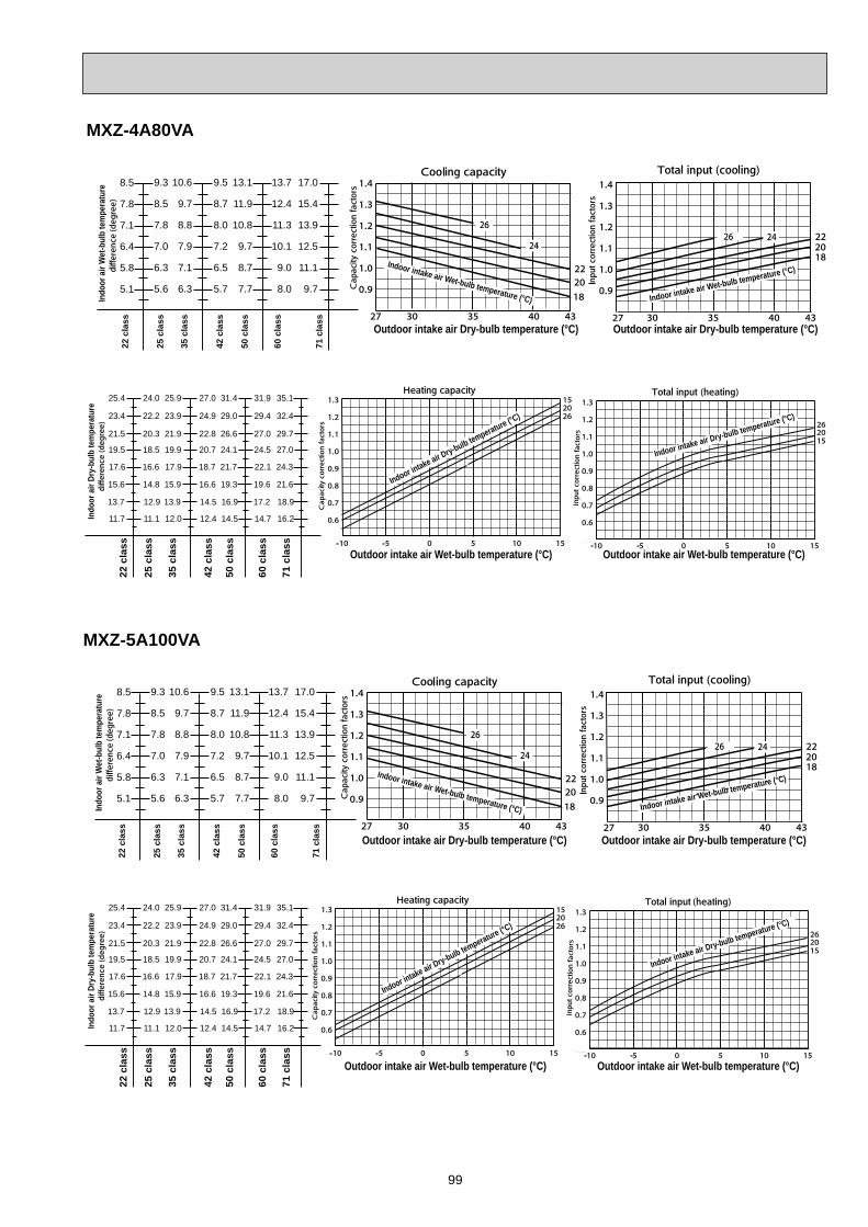
99
MXZ-4A80VA22
cla
ss
8.5
7.8
7.1
6.4
5.8
5.1
9.3
8.5
7.8
7.0
6.3
5.6
71 c
lass
60 c
lass
10.6
9.7
8.8
7.9
7.1
6.3
9.5
8.7
8.0
7.2
6.5
5.7
13.7
12.4
11.3
10.1
9.0
8.0
17.0
15.4
13.9
12.5
11.1
9.7
42 c
lass
35 c
lass
13.1
11.9
10.8
9.7
8.7
7.7
50 c
lass
25 c
lass
Indo
or a
ir W
et-b
ulb
tem
pera
ture
Outdoor intake air Dry-bulb temperature (°C) Outdoor intake air Dry-bulb temperature (°C)
Indoor intake air Wet-bulb temperature (°C) Indoor intake air Wet-bulb temperature (°C)
25.4
23.4
21.5
19.5
17.6
15.6
13.7
11.7
24.0
22.2
20.3
18.5
16.6
14.8
12.9
11.1
22 c
lass
25 c
lass
60 c
lass
71 c
lass
25.9
23.9
21.9
19.9
17.9
15.9
13.9
12.0
27.0
24.9
22.8
20.7
18.7
16.6
14.5
12.4
31.9
29.4
27.0
24.5
22.1
19.6
17.2
14.7
35.1
32.4
29.7
27.0
24.3
21.6
18.9
16.2
35 c
lass
42 c
lass
31.4
29.0
26.6
24.1
21.7
19.3
16.9
14.5
50 c
lass
Indo
or a
ir Dr
y-bu
lb te
mpe
ratu
re
Outdoor intake air Wet-bulb temperature (°C) Outdoor intake air Wet-bulb temperature (°C)
Indoor intake air Dry-bulb temperature (°C)
Indoor intake air Dry-bulb temperature (°C)
MXZ-5A100VA
22 c
lass
8.5
7.8
7.1
6.4
5.8
5.1
9.3
8.5
7.8
7.0
6.3
5.6
71 c
lass
60 c
lass
10.6
9.7
8.8
7.9
7.1
6.3
9.5
8.7
8.0
7.2
6.5
5.7
13.7
12.4
11.3
10.1
9.0
8.0
17.0
15.4
13.9
12.5
11.1
9.7
42 c
lass
35 c
lass
13.1
11.9
10.8
9.7
8.7
7.7
50 c
lass
25 c
lass
Outdoor intake air Dry-bulb temperature (°C) Outdoor intake air Dry-bulb temperature (°C)
Indoor intake air Wet-bulb temperature (°C) Indoor intake air Wet-bulb temperature (°C)
Indo
or a
ir W
et-b
ulb
tem
pera
ture
25.4
23.4
21.5
19.5
17.6
15.6
13.7
11.7
24.0
22.2
20.3
18.5
16.6
14.8
12.9
11.1
22 c
lass
25 c
lass
60 c
lass
71 c
lass
25.9
23.9
21.9
19.9
17.9
15.9
13.9
12.0
27.0
24.9
22.8
20.7
18.7
16.6
14.5
12.4
31.9
29.4
27.0
24.5
22.1
19.6
17.2
14.7
35.1
32.4
29.7
27.0
24.3
21.6
18.9
16.2
35 c
lass
42 c
lass
31.4
29.0
26.6
24.1
21.7
19.3
16.9
14.5
50 c
lass
Outdoor intake air Wet-bulb temperature (°C) Outdoor intake air Wet-bulb temperature (°C)
Indoor intake air Dry-bulb temperature (°C)
Indoor intake air Dry-bulb temperature (°C)
Indo
or a
ir Dr
y-bu
lb te
mpe
ratu
re
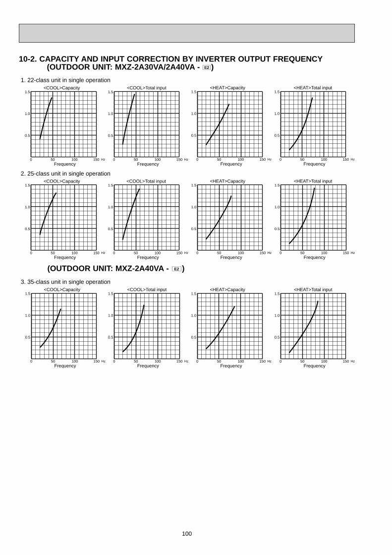
100
10-2. CAPACITY AND INPUT CORRECTION BY INVERTER OUTPUT FREQUENCY (OUTDOOR UNIT: MXZ-2A30VA/2A40VA - E2 )
0 50 100 150
0.5
1.0
1.5<COOL>Capacity
FrequencyHz 0 50 100 150
0.5
1.0
1.5<COOL>Total input
FrequencyHz 0 50 100 150
0.5
1.0
1.5<HEAT>Capacity
FrequencyHz
0 50 100 150
0.5
1.0
1.5<COOL>Capacity
FrequencyHz 0 50 100 150
0.5
1.0
1.5<HEAT>Capacity
FrequencyHz
0 50 100 150
0.5
1.0
1.5<COOL>Capacity
FrequencyHz 0 50 100 150
0.5
1.0
1.5<HEAT>Capacity
FrequencyHz
1. 22-class unit in single operation
2. 25-class unit in single operation
3. 35-class unit in single operation
0 50 100 150
0.5
1.0
1.5<HEAT>Total input
FrequencyHz
0 50 100 150
0.5
1.0
1.5<COOL>Total input
FrequencyHz 0 50 100 150
0.5
1.0
1.5<HEAT>Total input
FrequencyHz
0 50 100 150
0.5
1.0
1.5<COOL>Total input
FrequencyHz 0 50 100 150
0.5
1.0
1.5<HEAT>Total input
FrequencyHz
(OUTDOOR UNIT: MXZ-2A40VA - E2 )
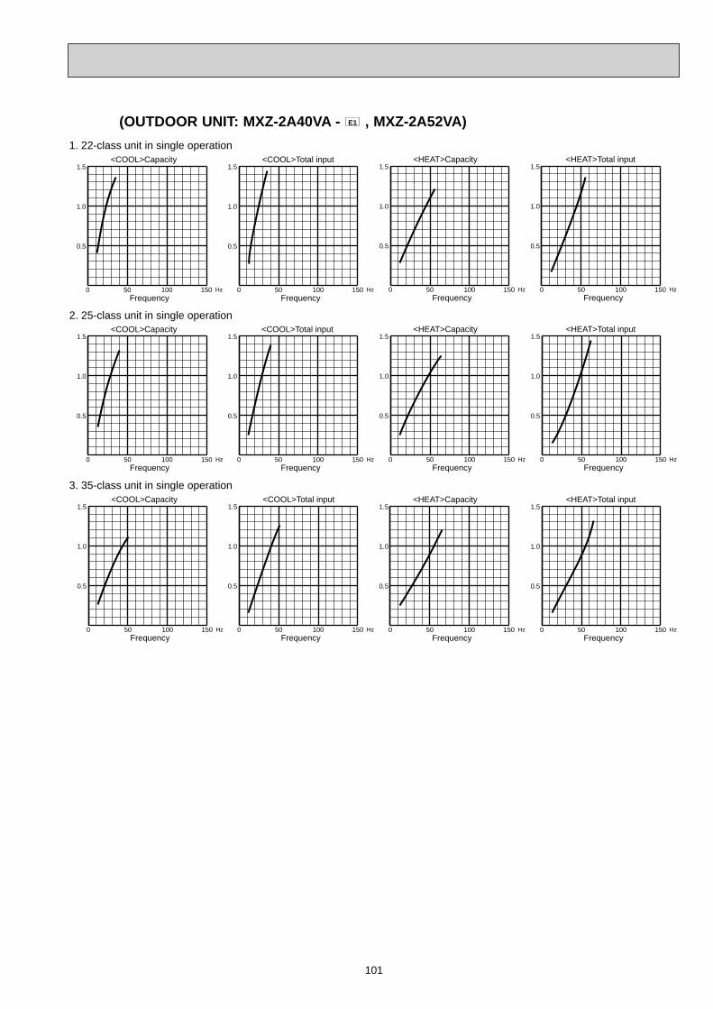
101
(OUTDOOR UNIT: MXZ-2A40VA - E1 , MXZ-2A52VA)
0 50 100 150
0.5
1.0
1.5<COOL>Capacity
FrequencyHz 0 50 100 150
0.5
1.0
1.5<COOL>Total input
FrequencyHz 0 50 100 150
0.5
1.0
1.5<HEAT>Capacity
FrequencyHz
0 50 100 150
0.5
1.0
1.5<COOL>Capacity
FrequencyHz 0 50 100 150
0.5
1.0
1.5<HEAT>Capacity
FrequencyHz
0 50 100 150
0.5
1.0
1.5<COOL>Capacity
FrequencyHz 0 50 100 150
0.5
1.0
1.5<HEAT>Capacity
FrequencyHz
1. 22-class unit in single operation
2. 25-class unit in single operation
3. 35-class unit in single operation
0 50 100 150
0.5
1.0
1.5<HEAT>Total input
FrequencyHz
0 50 100 150
0.5
1.0
1.5<COOL>Total input
FrequencyHz 0 50 100 150
0.5
1.0
1.5<HEAT>Total input
FrequencyHz
0 50 100 150
0.5
1.0
1.5<COOL>Total input
FrequencyHz 0 50 100 150
0.5
1.0
1.5<HEAT>Total input
FrequencyHz

102
(OUTDOOR UNIT: MXZ-3A54VA)
0 50 100 150
0.5
1.0
1.5<COOL>Capacity
FrequencyHz 0 50 100 150
0.5
1.0
1.5<COOL>Total input
FrequencyHz 0 50 100 150
0.5
1.0
1.5<HEAT>Capacity
FrequencyHz
0 50 100 150
0.5
1.0
1.5<COOL>Capacity
FrequencyHz 0 50 100 150
0.5
1.0
1.5<HEAT>Capacity
FrequencyHz
0 50 100 150
0.5
1.0
1.5<COOL>Capacity
FrequencyHz 0 50 100 150
0.5
1.0
1.5<HEAT>Capacity
FrequencyHz
0 50 100 150
0.5
1.0
1.5<COOL>Capacity
FrequencyHz 0 50 100 150
0.5
1.0
1.5<HEAT>Capacity
FrequencyHz
1. 22-class unit in single operation
2. 25-class unit in single operation
3. 35-class unit in single operation
5. 50-class unit in single operation
0 50 100 150
0.5
1.0
1.5<HEAT>Total input
FrequencyHz
0 50 100 150
0.5
1.0
1.5<COOL>Total input
FrequencyHz 0 50 100 150
0.5
1.0
1.5<HEAT>Total input
FrequencyHz
0 50 100 150
0.5
1.0
1.5<COOL>Total input
FrequencyHz 0 50 100 150
0.5
1.0
1.5<HEAT>Total input
FrequencyHz
0 50 100 150
0.5
1.0
1.5<COOL>Total input
FrequencyHz 0 50 100 150
0.5
1.0
1.5<HEAT>Total input
FrequencyHz
<COOL>Capacity
FrequencyHz
<HEAT>Capacity
FrequencyHz
4. 42-class unit in single operation<COOL>Total input
FrequencyHz
<HEAT>Total input
FrequencyHz0 50 100 150
0.5
1.0
1.5
0 50 100 150
0.5
1.0
1.5
0 50 100 150
0.5
1.0
1.5
0 50 100 150
0.5
1.0
1.5

103
(OUTDOOR UNIT: MXZ-4A71VA)
0 50 100 150
0.5
1.0
1.5<COOL>Capacity
FrequencyHz 0 50 100 150
0.5
1.0
1.5<COOL>Total input
FrequencyHz 0 50 100 150
0.5
1.0
1.5<HEAT>Capacity
FrequencyHz
0 50 100 150
0.5
1.0
1.5<COOL>Capacity
FrequencyHz 0 50 100 150
0.5
1.0
1.5<HEAT>Capacity
FrequencyHz
0 50 100 150
0.5
1.0
1.5<COOL>Capacity
FrequencyHz 0 50 100 150
0.5
1.0
1.5<HEAT>Capacity
FrequencyHz
1. 22-class unit in single operation
2. 25-class unit in single operation
3. 35-class unit in single operation
0 50 100 150
0.5
1.0
1.5<HEAT>Total input
FrequencyHz
0 50 100 150
0.5
1.0
1.5<COOL>Total input
FrequencyHz 0 50 100 150
0.5
1.0
1.5<HEAT>Total input
FrequencyHz
0 50 100 150
0.5
1.0
1.5<COOL>Total input
FrequencyHz 0 50 100 150
0.5
1.0
1.5<HEAT>Total input
FrequencyHz

104
(OUTDOOR UNIT: MXZ-4A71VA)
0 50 100 150
0.5
1.0
1.5<COOL>Capacity
FrequencyHz 0 50 100 150
0.5
1.0
1.5
0 50 100 150
0.5
1.0
1.5<HEAT>Capacity
FrequencyHz
5. 50-class unit in single operation<COOL>Total input
FrequencyHz 0 50 100 150
0.5
1.0
1.5<HEAT>Total input
FrequencyHz
<COOL>Capacity
FrequencyHz
<HEAT>Capacity
FrequencyHz
4. 42-class unit in single operation<COOL>Total input
FrequencyHz
<HEAT>Total input
FrequencyHz
0 50 100 150
0.5
1.0
1.5<COOL>Capacity
FrequencyHz 0 50 100 150
0.5
1.0
1.5<COOL>Total input
FrequencyHz 0 50 100 150
0.5
1.0
1.5<HEAT>Capacity
FrequencyHz 0 50 100 150
0.5
1.0
1.5<HEAT>Total input
FrequencyHz
6. 60-class unit in single operation
0 50 100 150
0.5
1.0
1.5
0 50 100 150
0.5
1.0
1.5
0 50 100 150
0.5
1.0
1.5
0 50 100 150
0.5
1.0
1.5

105
(OUTDOOR UNIT: MXZ-4A80VA)
0 50 100 150
0.5
1.0
1.5<COOL>Capacity
FrequencyHz 0 50 100 150
0.5
1.0
1.5<COOL>Total input
FrequencyHz 0 50 100 150
0.5
1.0
1.5<HEAT>Capacity
FrequencyHz
0 50 100 150
0.5
1.0
1.5<COOL>Capacity
FrequencyHz 0 50 100 150
0.5
1.0
1.5<HEAT>Capacity
FrequencyHz
0 50 100 150
0.5
1.0
1.5<COOL>Capacity
FrequencyHz 0 50 100 150
0.5
1.0
1.5<HEAT>Capacity
FrequencyHz
1. 22-class unit in single operation
2. 25-class unit in single operation
3. 35-class unit in single operation
0 50 100 150
0.5
1.0
1.5<HEAT>Total input
FrequencyHz
0 50 100 150
0.5
1.0
1.5<COOL>Total input
FrequencyHz 0 50 100 150
0.5
1.0
1.5<HEAT>Total input
FrequencyHz
0 50 100 150
0.5
1.0
1.5<COOL>Total input
FrequencyHz 0 50 100 150
0.5
1.0
1.5<HEAT>Total input
FrequencyHz
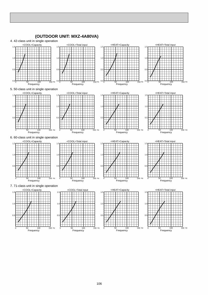
106
0 50 100 150
0.5
1.0
1.5<COOL>Capacity
FrequencyHz 0 50 100 150
0.5
1.0
1.5<COOL>Total input
FrequencyHz 0 50 100 150
0.5
1.0
1.5<HEAT>Capacity
FrequencyHz
7. 71-class unit in single operation
0 50 100 150
0.5
1.0
1.5<HEAT>Total input
FrequencyHz
(OUTDOOR UNIT: MXZ-4A80VA)
0 50 100 150
0.5
1.0
1.5<COOL>Capacity
FrequencyHz 0 50 100 150
0.5
1.0
1.5<HEAT>Capacity
FrequencyHz
5. 50-class unit in single operation
0 50 100 150
0.5
1.0
1.5<COOL>Capacity
FrequencyHz 0 50 100 150
0.5
1.0
1.5<COOL>Total input
FrequencyHz 0 50 100 150
0.5
1.0
1.5<HEAT>Capacity
FrequencyHz 0 50 100 150
0.5
1.0
1.5<HEAT>Total input
FrequencyHz
6. 60-class unit in single operation
0 50 100 150
0.5
1.0
1.5<COOL>Total input
FrequencyHz 0 50 100 150
0.5
1.0
1.5<HEAT>Total input
FrequencyHz
<COOL>Capacity
FrequencyHz
<HEAT>Capacity
FrequencyHz
4. 42-class unit in single operation<COOL>Total input
FrequencyHz
<HEAT>Total input
FrequencyHz0 50 100 1500.0
0.5
1.0
1.5
0 50 100 1500.0
0.5
1.0
1.5
0 50 100 1500.0
0.5
1.0
1.5
0 50 100 1500.0
0.5
1.0
1.5
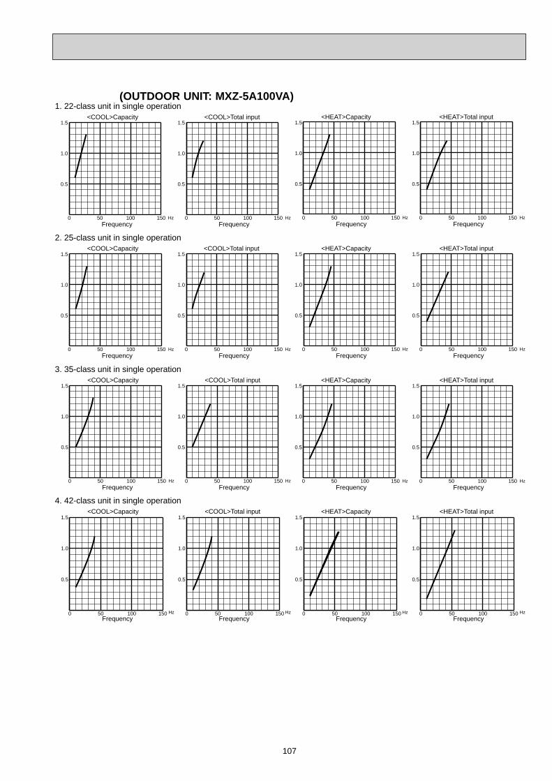
107
(OUTDOOR UNIT: MXZ-5A100VA)
0 50 100 150
0.5
1.0
1.5<COOL>Capacity
FrequencyHz 0 50 100 150
0.5
1.0
1.5<COOL>Total input
FrequencyHz 0 50 100 150
0.5
1.0
1.5<HEAT>Capacity
FrequencyHz
0 50 100 150
0.5
1.0
1.5<COOL>Capacity
FrequencyHz 0 50 100 150
0.5
1.0
1.5<HEAT>Capacity
FrequencyHz
0 50 100 150
0.5
1.0
1.5<COOL>Capacity
FrequencyHz 0 50 100 150
0.5
1.0
1.5<HEAT>Capacity
FrequencyHz
1. 22-class unit in single operation
2. 25-class unit in single operation
3. 35-class unit in single operation
0 50 100 150
0.5
1.0
1.5<HEAT>Total input
FrequencyHz
0 50 100 150
0.5
1.0
1.5<COOL>Total input
FrequencyHz 0 50 100 150
0.5
1.0
1.5<HEAT>Total input
FrequencyHz
0 50 100 150
0.5
1.0
1.5<COOL>Total input
FrequencyHz 0 50 100 150
0.5
1.0
1.5<HEAT>Total input
FrequencyHz
<COOL>Capacity
FrequencyHz
<HEAT>Capacity
FrequencyHz
4. 42-class unit in single operation<COOL>Total input
FrequencyHz
<HEAT>Total input
FrequencyHz0 50 100 150
0.5
1.0
1.5
0 50 100 150
0.5
1.0
1.5
0 50 100 150
0.5
1.0
1.5
0 50 100 150
0.5
1.0
1.5
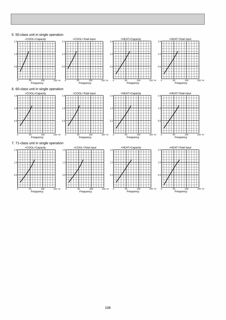
108
0 50 100 150
0.5
1.0
1.5<COOL>Capacity
FrequencyHz 0 50 100 150
0.5
1.0
1.5<COOL>Total input
FrequencyHz 0 50 100 150
0.5
1.0
1.5<HEAT>Capacity
FrequencyHz 0 50 100 150
0.5
1.0
1.5<HEAT>Total input
FrequencyHz
6. 60-class unit in single operation
0 50 100 150
0.5
1.0
1.5<COOL>Capacity
FrequencyHz 0 50 100 150
0.5
1.0
1.5<COOL>Total input
FrequencyHz 0 50 100 150
0.5
1.0
1.5<HEAT>Capacity
FrequencyHz
7. 71-class unit in single operation
0 50 100 150
0.5
1.0
1.5<HEAT>Total input
FrequencyHz
0 50 100 150
0.5
1.0
1.5<COOL>Capacity
FrequencyHz 0 50 100 150
0.5
1.0
1.5<HEAT>Capacity
FrequencyHz
5. 50-class unit in single operation
0 50 100 150
0.5
1.0
1.5<COOL>Total input
FrequencyHz 0 50 100 150
0.5
1.0
1.5<HEAT>Total input
FrequencyHz

109
1. Press EMERGENCY OPERATION switch to COOL or HEAT mode (COOL : Press once, HEAT : Press twice).2. Test run operation starts and continues to operate for 30 minutes.3. Compressor operates at rated frequency.4. Indoor fan operates at High speed.5. After 30 minutes, test run operation finishes and EMERGENCY OPERATION starts (Operation frequency of compressor varies).6. To cancel test run operation (EMERGENCY OPERATION), press EMERGENCY OPERATION switch or any button on remote controller.
10-3. TEST RUN OPERATION (How to operate fixed-frequency operation)
Both indoor and outdoor unit are under the same temperature/humidity condition.
Operation : TEST RUN OPERATION (Refer to 10-3.)
Dry-bulb temperature ( ) Relative humidity (%)
20 50
25 60
30 70
10-4. OUTDOOR LOW PRESSURE AND OUTDOOR UNIT CURRENT (single operation)NOTE: The unit of pressure has been changed to MPa on the international system of units (SI unit system). The conversion factor is : 1 (MPa[Gauge]) = 10.2(kgf/cm2 [Gauge])(1) COOL operation
MXZ-2A30VA MXZ-2A40VA - E2
Ambient temperature ( )Ambient humidity (%)
Ambient temperature ( )Ambient humidity (%)
Out
door
low
pre
ssur
e
(MPa[Gauge])
Out
door
uni
t cur
rent
(A)
15 20 25 30 3550 60 70
0.7
0.8
0.9
1.0
1.2
1.3
1.4
(%)15 20 25 30 35
50 60 70 (%)
42Hz
1
2
3
4
42Hz
14
13
12
11
10
9
7
8
1.1
Ambient temperature ( )Ambient humidity (%)
Ambient temperature ( )Ambient humidity (%)
Out
door
low
pre
ssur
e
(MPa[Gauge])
Out
door
uni
t cur
rent
(A)
15 20 25 30 3550 60 70
0.7
0.8
0.9
1.0
1.2
1.3
1.4
(%)15 20 25 30 35
50 60 70 (%)
42Hz
1
2
3
4
42Hz
14
13
12
11
10
9
7
8
1.1
Ambient temperature ( )Ambient humidity (%)
Ambient temperature ( )Ambient humidity (%)
Out
door
low
pre
ssur
e
(MPa[Gauge])
Out
door
uni
t cur
rent
(A)
15 20 25 30 3550 60 70
0.7
0.8
0.9
1.0
1.2
1.3
1.4
(%)15 20 25 30 35
50 60 70 (%)
42Hz
1
2
3
4
42Hz
14
13
12
11
10
9
7
8
1.1
22-class unit 25-class unit
35-class unitMXZ-2A40VA- E2
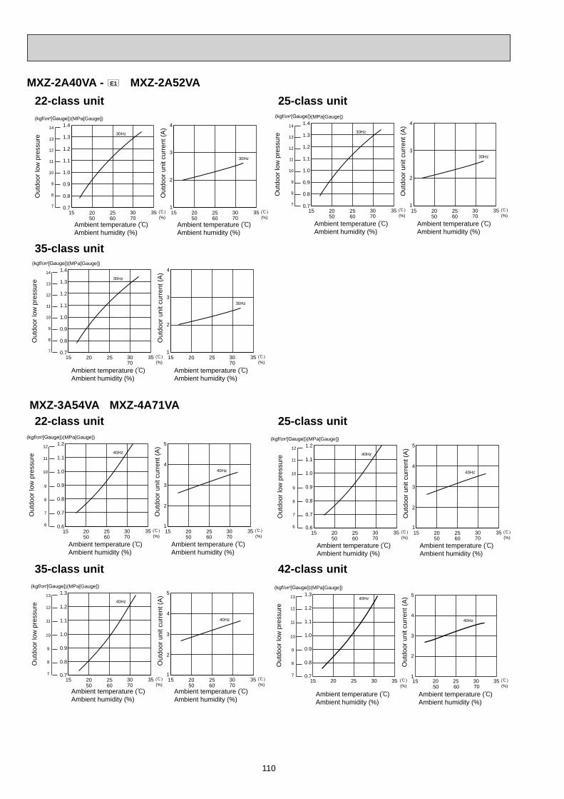
110
Out
door
low
pre
ssur
e
(MPa[Gauge])
Out
door
uni
t cur
rent
(A)
15 20 25 30 3570
0.7
0.8
0.9
1.0
1.2
1.3
1.4
(%)15 20 25 30 35
70 (%)
30Hz
1
2
3
4
30Hz
14
13
12
11
10
9
7
8
1.1
Ambient temperature ( )Ambient humidity (%)
Ambient temperature ( )Ambient humidity (%)
35-class unit
MXZ-3A54VA MXZ-4A71VA 22-class unit
Ambient temperature ( )Ambient humidity (%)
Ambient temperature ( )Ambient humidity (%)
Out
door
low
pre
ssur
e
(MPa[Gauge])
Out
door
uni
t cur
rent
(A)
15 20 25 30 3550 60 70
0.6
0.7
0.8
0.9
1.0
1.1
1.2
(%)15 20 25 30 35
50 60 70 (%)
40Hz
1
2
3
4
5
40Hz
12
11
10
9
8
7
6
Ambient temperature ( )Ambient humidity (%)
Ambient temperature ( )Ambient humidity (%)
Out
door
low
pre
ssur
e
(MPa[Gauge])
Out
door
uni
t cur
rent
(A)
0.6
0.7
0.8
0.9
1.0
1.1
1.240Hz
1
2
3
4
5
40Hz
12
11
10
9
8
7
615 20 25 30 35
50 60 70 (%)15 20 25 30 35
50 60 70 (%)
Ambient temperature ( )Ambient humidity (%)
Ambient temperature ( )Ambient humidity (%)
Out
door
low
pre
ssur
e
(MPa[Gauge])
Out
door
uni
t cur
rent
(A)
0.7
0.8
0.9
1.0
1.1
1.2
1.340Hz
1
2
3
4
5
40Hz
13
12
11
10
9
8
715 20 25 30 35
50 60 70 (%)15 20 25 30 35
50 60 70 (%)
Ambient temperature ( )Ambient humidity (%)
Ambient temperature ( )Ambient humidity (%)
Out
door
low
pre
ssur
e
(MPa[Gauge])
Out
door
uni
t cur
rent
(A)13
12
11
10
9
8
7
(%) 50 60 70 (%)15 20 25 30 35
0.7
0.8
0.9
1.0
1.1
1.2
1.340Hz
15 20 25 30 351
2
3
4
5
40Hz
25-class unit
35-class unit 42-class unit
MXZ-2A40VA - E1 MXZ-2A52VA
Ambient temperature ( )Ambient humidity (%)
Ambient temperature ( )Ambient humidity (%)
Out
door
low
pre
ssur
e
(MPa[Gauge])
Out
door
uni
t cur
rent
(A)
15 20 25 30 3550 60 70
0.7
0.8
0.9
1.0
1.2
1.3
1.4
(%)15 20 25 30 35
50 60 70 (%)
30Hz
1
2
3
4
30Hz
14
13
12
11
10
9
7
8
1.1
Ambient temperature ( )Ambient humidity (%)
Ambient temperature ( )Ambient humidity (%)
Out
door
low
pre
ssur
e
(MPa[Gauge])
Out
door
uni
t cur
rent
(A)
15 20 25 30 3550 60 70
0.7
0.8
0.9
1.0
1.2
1.3
1.4
(%)15 20 25 30 35
50 60 70 (%)
30Hz
1
2
3
4
30Hz
14
13
12
11
10
9
7
8
1.1
22-class unit 25-class unit
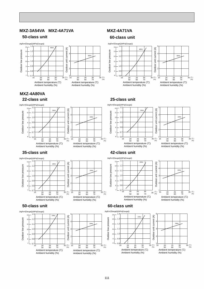
111
MXZ-4A80VA 22-class unit
Ambient temperature ( )Ambient humidity (%)
Ambient temperature ( )Ambient humidity (%)
Out
door
low
pre
ssur
e
(MPa[Gauge])
Out
door
uni
t cur
rent
(A)
15 20 25 30 3550 60 70
0.6
0.7
0.8
0.9
1.0
1.1
1.2
(%)15 20 25 30 35
50 60 70 (%)
24Hz
1
2
3
4
5
24Hz
12
11
10
9
8
7
6
Ambient temperature ( )Ambient humidity (%)
Ambient temperature ( )Ambient humidity (%)
Out
door
low
pre
ssur
e
(MPa[Gauge])
Out
door
uni
t cur
rent
(A)
0.6
0.7
0.8
0.9
1.0
1.1
1.224Hz
1
2
3
4
5
24Hz
12
11
10
9
8
7
615 20 25 30 35
50 60 70 (%)15 20 25 30 35
50 60 70 (%)
Ambient temperature ( )Ambient humidity (%)
Ambient temperature ( )Ambient humidity (%)
Out
door
low
pre
ssur
e
(MPa[Gauge])
Out
door
uni
t cur
rent
(A)
0.7
0.8
0.9
1.0
1.1
1.2
1.324Hz
1
2
3
4
5
24Hz
13
12
11
10
9
8
715 20 25 30 35
50 60 70 (%)15 20 25 30 35
50 60 70 (%)
Ambient temperature ( )Ambient humidity (%)
Ambient temperature ( )Ambient humidity (%)
Out
door
low
pre
ssur
e
(MPa[Gauge])O
utdo
or u
nit c
urre
nt (A
)13
12
11
10
9
8
7
50 60 70 (%) 50 60 70 (%)15 20 25 30 35
0.7
0.8
0.9
1.0
1.1
1.2
1.324Hz
15 20 25 30 351
2
3
4
5
24Hz
Ambient temperature ( )Ambient humidity (%)
Ambient temperature ( )Ambient humidity (%)
Out
door
low
pre
ssur
e
(MPa[Gauge])
Out
door
uni
t cur
rent
(A)
0.8
0.9
1.0
1.1
1.2
1.3
1.424Hz
1
2
3
4
5
24Hz
14
13
12
11
10
9
815 20 25 30 35
50 60 70 (%)15 20 25 30 35
50 60 70 (%)
25-class unit
35-class unit 42-class unit
60-class unit
Ambient temperature ( )Ambient humidity (%)
Ambient temperature ( )Ambient humidity (%)
Out
door
low
pre
ssur
e
(MPa[Gauge])
Out
door
uni
t cur
rent
(A)
0.8
0.9
1.0
1.1
1.2
1.3
1.440Hz
1
2
3
4
5
40Hz
14
13
12
11
10
9
815 20 25 30 35
50 60 70 (%)15 20 25 30 35
50 60 70 (%)
60-class unitMXZ-3A54VA MXZ-4A71VA
Ambient temperature ( )Ambient humidity (%)
Ambient temperature ( )Ambient humidity (%)
Out
door
low
pre
ssur
e
(MPa[Gauge])
Out
door
uni
t cur
rent
(A)
0.7
0.8
0.9
1.0
1.1
1.2
1.340Hz
1
2
3
4
5
40Hz
13
12
11
10
9
8
715 20 25 30 35
50 60 70 (%)15 20 25 30 35
50 60 70 (%)
50-class unit
Ambient temperature ( )Ambient humidity (%)
Ambient temperature ( )Ambient humidity (%)
Out
door
low
pre
ssur
e
(MPa[Gauge])
Out
door
uni
t cur
rent
(A)
0.7
0.8
0.9
1.0
1.1
1.2
1.324Hz
1
2
3
4
5
24Hz
13
12
11
10
9
8
715 20 25 30 35
50 60 70 (%)15 20 25 30 35
50 60 70 (%)
50-class unit
MXZ-4A71VA

112
MXZ-5A100VA 22-class unit
Ambient temperature ( )Ambient humidity (%)
Ambient temperature ( )Ambient humidity (%)
Out
door
low
pre
ssur
e
(MPa[Gauge])
Out
door
uni
t cur
rent
(A)
15 20 25 30 3550 60 70
0.6
0.7
0.8
0.9
1.0
1.1
1.2
(%)15 20 25 30 35
50 60 70 (%)
24Hz
1
2
3
4
5
24Hz
12
11
10
9
8
7
6
Ambient temperature ( )Ambient humidity (%)
Ambient temperature ( )Ambient humidity (%)
Out
door
low
pre
ssur
e
(MPa[Gauge])
Out
door
uni
t cur
rent
(A)
0.6
0.7
0.8
0.9
1.0
1.1
1.224Hz
1
2
3
4
5
24Hz
12
11
10
9
8
7
615 20 25 30 35
50 60 70 (%)15 20 25 30 35
50 60 70 (%)
Ambient temperature ( )Ambient humidity (%)
Ambient temperature ( )Ambient humidity (%)
Out
door
low
pre
ssur
e
(MPa[Gauge])
Out
door
uni
t cur
rent
(A)
0.7
0.8
0.9
1.0
1.1
1.2
1.324Hz
1
2
3
4
5
24Hz
13
12
11
10
9
8
715 20 25 30 35
50 60 70 (%)15 20 25 30 35
50 60 70 (%)
Ambient temperature ( )Ambient humidity (%)
Ambient temperature ( )Ambient humidity (%)
Out
door
low
pre
ssur
e
(MPa[Gauge])
Out
door
uni
t cur
rent
(A)
0.7
0.8
0.9
1.0
1.1
1.2
1.324Hz
1
2
3
4
5
24Hz
13
12
11
10
9
8
715 20 25 30 35
50 60 70 (%)15 20 25 30 35
50 60 70 (%)
Ambient temperature ( )Ambient humidity (%)
Ambient temperature ( )Ambient humidity (%)
Out
door
low
pre
ssur
e
(MPa[Gauge])
Out
door
uni
t cur
rent
(A)
0.8
0.9
1.0
1.1
1.2
1.3
1.424Hz
1
2
3
4
5
24Hz
14
13
12
11
10
9
815 20 25 30 35
50 60 70 (%)15 20 25 30 35
50 60 70 (%)
25-class unit 35-class unit
50-class unit
60-class unit
Ambient temperature ( )Ambient humidity (%)
Ambient temperature ( )Ambient humidity (%)
Out
door
low
pre
ssur
e
(MPa[Gauge])
Out
door
uni
t cur
rent
(A)
0.8
0.9
1.0
1.1
1.2
1.3
1.424Hz
1
2
3
4
5
24Hz
14
13
12
11
10
9
815 20 25 30 35
50 60 70 (%)15 20 25 30 35
50 60 70 (%)
71-class unit
Ambient temperature ( )Ambient humidity (%)
Ambient temperature ( )Ambient humidity (%)
Out
door
low
pre
ssur
e
(MPa[Gauge])
Out
door
uni
t cur
rent
(A)
0.8
0.9
1.0
1.1
1.2
1.3
1.424Hz
1
2
3
4
5
24Hz
14
13
12
11
10
9
815 20 25 30 35
50 60 70 (%)15 20 25 30 35
50 60 70 (%)
71-class unitMXZ-4A80VA
Ambient temperature ( )Ambient humidity (%)
Ambient temperature ( )Ambient humidity (%)
Out
door
low
pre
ssur
e
(MPa[Gauge])
Out
door
uni
t cur
rent
(A)13
12
11
10
9
8
7
50 60 70 (%) 50 60 70 (%)15 20 25 30 35
0.7
0.8
0.9
1.0
1.1
1.2
1.324Hz
15 20 25 30 351
2
3
4
5
24Hz
42-class unit
MXZ-5A100VA
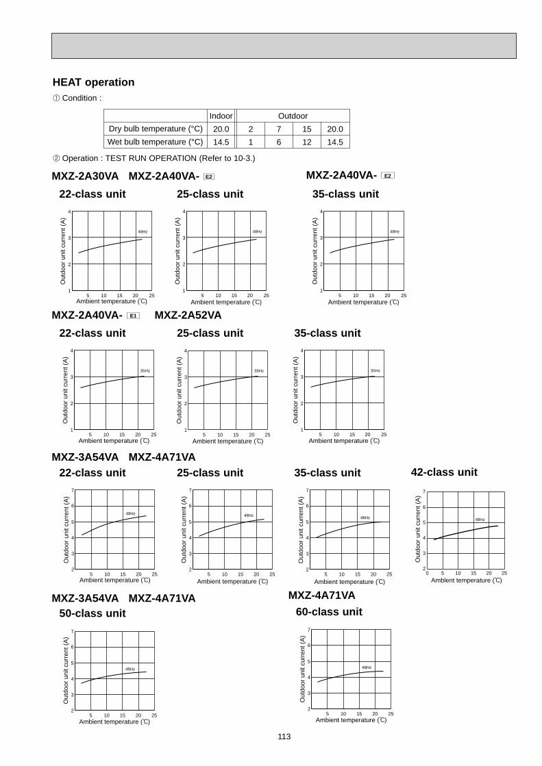
113
Condition :
Operation : TEST RUN OPERATION (Refer to 10-3.)
HEAT operation
Dry bulb temperature (°C)Indoor20.014.5
21
Outdoor76
1512
20.014.5Wet bulb temperature (°C)
MXZ-2A30VA MXZ-2A40VA- E2
5 10 15 20 251
2
3
4
Ambient temperature ( )
48Hz
Out
door
uni
t cur
rent
(A)
22-class unit 25-class unit
1
2
3
4
Ambient temperature ( )
Out
door
uni
t cur
rent
(A)
5 10 15 20 25
48Hz
35-class unit
5 10 15 20 251
2
3
4
Ambient temperature ( )
48Hz
Out
door
uni
t cur
rent
(A)
MXZ-2A40VA- E1 MXZ-2A52VA
5 10 15 20 251
2
3
4
Ambient temperature ( )
35Hz
Out
door
uni
t cur
rent
(A)
22-class unit 25-class unit
Ambient temperature ( )
Out
door
uni
t cur
rent
(A)
1
2
3
4
5 10 15 20 25
35Hz
35-class unit
1
2
3
4
Ambient temperature ( )
Out
door
uni
t cur
rent
(A)
35Hz
5 10 15 20 25
MXZ-3A54VA MXZ-4A71VA
5 10 15 20 252
3
4
5
6
7
Ambient temperature ( )
48Hz
Out
door
uni
t cur
rent
(A)
22-class unit 25-class unit
5 10 15 20 252
3
4
5
6
7
Ambient temperature ( )
48Hz
Out
door
uni
t cur
rent
(A)
35-class unit
5 10 15 20 252
3
4
5
6
7
Ambient temperature ( )
48Hz
Out
door
uni
t cur
rent
(A)
42-class unit
Ambient temperature ( )
Out
door
uni
t cur
rent
(A)
48Hz
0 5 10 15 20 252
3
4
5
6
7
5 10 15 20 252
3
4
5
6
7
Ambient temperature ( )
48Hz
Out
door
uni
t cur
rent
(A)
60-class unitMXZ-4A71VA
MXZ-2A40VA- E2
50-class unit
5 10 15 20 252
3
4
5
6
7
Ambient temperature ( )
48Hz
Out
door
uni
t cur
rent
(A)
MXZ-3A54VA MXZ-4A71VA

114
5 10 15 20 252
3
4
5
6
7
Ambient temperature ( )
32Hz
Out
door
uni
t cur
rent
(A)
22-class unit 25-class unit
5 10 15 20 252
3
4
5
6
7
Ambient temperature ( )
32Hz
Out
door
uni
t cur
rent
(A)
35-class unit
5 10 15 20 252
3
4
5
6
7
Ambient temperature ( )
32Hz
Out
door
uni
t cur
rent
(A)
50-class unit
5 10 15 20 252
3
4
5
6
7
Ambient temperature ( )
32Hz
Out
door
uni
t cur
rent
(A)
5 10 15 20 252
3
4
5
6
7
Ambient temperature ( )
32Hz
Out
door
uni
t cur
rent
(A)
60-class unit 71-class unit
5 10 15 20 252
3
4
5
6
7
Ambient temperature ( )
32Hz
Out
door
uni
t cur
rent
(A)
MXZ-4A80VA
5 10 15 20 252
3
4
5
6
7
Ambient temperature ( )
32Hz
Out
door
uni
t cur
rent
(A)
22-class unit 25-class unit
5 10 15 20 252
3
4
5
6
7
Ambient temperature ( )
32Hz
Out
door
uni
t cur
rent
(A)
35-class unit
5 10 15 20 252
3
4
5
6
7
Ambient temperature ( )
32Hz
Out
door
uni
t cur
rent
(A)
50-class unit
5 10 15 20 252
3
4
5
6
7
Ambient temperature ( )
32Hz
Out
door
uni
t cur
rent
(A)
5 10 15 20 252
3
4
5
6
7
Ambient temperature ( )
32Hz
Out
door
uni
t cur
rent
(A)
60-class unit 71-class unit
5 10 15 20 252
3
4
5
6
7
Ambient temperature ( )
32Hz
Out
door
uni
t cur
rent
(A)
MXZ-5A100VA
42-class unit
Ambient temperature ( )
Out
door
uni
t cur
rent
(A)
32Hz
0 5 10 15 20 252
3
4
5
6
7
42-class unit
Ambient temperature ( )
Out
door
uni
t cur
rent
(A)
32Hz
0 5 10 15 20 252
3
4
5
6
7
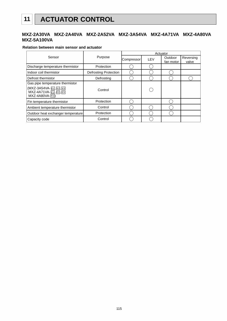
115
ACTUATOR CONTROL11
Relation between main sensor and actuator
Discharge temperature thermistor
Indoor coil thermistor
Defrost thermistorGas pipe temperature thermistor(MXZ-3A54VA- E1 , E2 , E3
MXZ-4A71VA- E1 , E2 , E3
MXZ-4A80VA- E1 )
Fin temperature thermistor
Ambient temperature thermistor
Outdoor heat exchanger temperature
Capacity code
Purpose
Protection
Defrosting Protection
Defrosting
Control
Protection
Control
Protection
Control
Compressor LEV Outdoorfan motor
Reversingvalve
SensorActuator
MXZ-2A30VA MXZ-2A40VA MXZ-2A52VA MXZ-3A54VA MXZ-4A71VA MXZ-4A80VAMXZ-5A100VA

116
Description of the function:With this function, you can lock the operation mode of theoutdoor unit. Once the operation mode is locked to eitherCOOL/DRY mode or HEAT mode, the air conditioner operates in that mode only.Initial setting is required to activate this function. Please explain about this function to your customers and ask them whether they want to use it.
[How to lock the operation mode]Turn OFF the power supply for the air conditionerbefore making the setting.Set SW1 on the display P.C. board or the outdoor electronic control P.C. board as shown in the right figure.Turn ON the power supply for the air conditioner.
ON ON
COOL/DRY HEAT
MXZ-2A30/2A40/2A52
ON
SW1 SW1
ON ON
COOL/DRY HEAT
SW1 SW1
MXZ-4A80VA- E2MXZ-5A100VA
SW2SW1
SW871
MXZ-3A54/4A71VAMXZ-4A80VA- E1
MXZ-2A30/2A40/2A52/3A54/4A71VAMXZ-4A80VA- E1
MXZ-4A80VA- E2 MXZ-5A100VA
ON
SERVICE FUNCTIONS12
12-1. LOCKING THE OPERATION MODE OF THE CONDITIONER (COOL, DRY, HEAT)
12-2. LOWERING THE OPERATING NOISE OF THE OUTDOOR UNITDescription of the function:With this function, you can lower the operating noise of the outdoor unit when the operation load is small,for example, during nighttime in COOL mode. However, please note that the cooling and heating capacity can also be lowered if this function is activated.
Initial setting is required to activate this function. Please explain about this function to your customers and ask them whether they want to use it.
[How to lower the operating noise]Turn OFF the power supply for the air conditioner before making the setting.Set the 3rd Dip Switch of SW1 on the display P.C. board or the outdoor electronic control P.C. board to ON to enable this function.Turn ON the power supply for the air conditioner.
ONSW1
MXZ-2A30VA MXZ-2A40VA MXZ-2A52VA MXZ-3A54VA MXZ-4A71VA MXZ-4A80VAMXZ-5A100VA
SW2SW1
SW871
ONSW2
1 2 3 4 5 6
SW1
ONSW2
1 2 3 4 5 6
ON
1 2 3 4
MXZ-4A80VA- E2MXZ-5A100VA
MXZ-3A54VA- E4 , E5 , E6 , E7MXZ-4A71VA- E4 , E5 , E6 , E7
MXZ-4A80VA- E2MXZ-5A100VA
MXZ-2A
JK
JK
If moisture gets into the refrigerant cycle, or when refrigerant is liquefied and collected in the compressor, it may interfere the start-up of the compressor.To improve start-up condition, the compressor is energized even while it is not operating. This is to generate heat at the winding.The compressor uses about 50 W when pre-heat control is turned ON.Pre-heat control is ON at initial setting.
[How to deactivate pre-heat control] Turn OFF the power supply for the air conditioner before making the setting. Set the 4th Dip Switch of SW2 on the outdoor electronic control P.C. board to ON to deactivate pre-heat control function (MXZ-4A80VA- E2 , MXZ-5A100VA). Set the 4th Dip Switch of SW1 on the outdoor electronic control P.C. board to ON to deactivate pre-heat control function (MXZ-3A54VA- E4 , E5 , E6 , E7 , MXZ-4A71VA- E4 , E5 , E6 , E7 ). Cut the JK wire of the inverter P.C. board to deactivate pre-heat control function (MXZ-2A).
Turn ON the power supply for the air conditioner.
NOTE: Pre-heat control will be turned OFF when the breaker is turned OFF.
12-3. PRE-HEAT CONTROL <MXZ-2A, MXZ-3A54VA- E4 , E5 , E6 , E7 , MXZ-4A71VA- E4 , E5 , E6 , E7 , MXZ-4A80VA- E2 , MXZ-5A100VA>
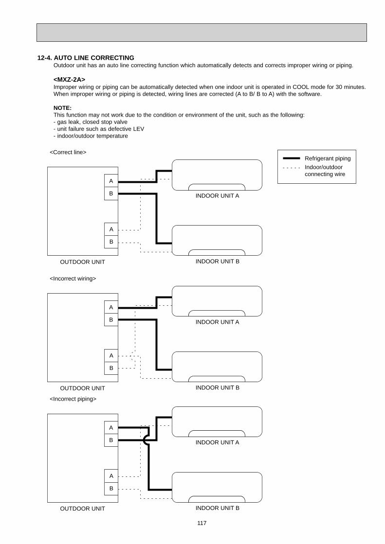
117
OUTDOOR UNIT
INDOOR UNIT A
INDOOR UNIT B
<Incorrect piping>
A
B
A
B
12-4. AUTO LINE CORRECTING Outdoor unit has an auto line correcting function which automatically detects and corrects improper wiring or piping.
<MXZ-2A>Improper wiring or piping can be automatically detected when one indoor unit is operated in COOL mode for 30 minutes. When improper wiring or piping is detected, wiring lines are corrected (A to B/ B to A) with the software.
NOTE:This function may not work due to the condition or environment of the unit, such as the following:- gas leak, closed stop valve- unit failure such as defective LEV- indoor/outdoor temperature
OUTDOOR UNIT
Refrigerant pipingIndoor/outdoorconnecting wire
OUTDOOR UNIT
INDOOR UNIT A
INDOOR UNIT A
INDOOR UNIT B
INDOOR UNIT B
<Correct line>
<Incorrect wiring>
A
B
A
B
A
B
A
B

118
The record of auto line correcting can be confirmed in the following way: Turn OFF the power supply. Turn ON the 4th Dip Switch of SW1 on the display P.C. board. Turn ON the power supply. Confirm the correction by the blinking of LED.
Turn OFF the power supply after the confirmation, and turn OFF the 4th Dip Switch of SW1 on the display P.C. board. Turn ON the power supply.NOTE: This function does not work when the jumper wire JGO on the inverter P.C. board is cut.
ON
MXZ-2A
SW1
LED1 (Red)Once
3 times
LED2 (Yellow)Once
3 times
Number of blinks Wiring line
Not correctedCorrected
<MXZ-4A80VA- E2 , MXZ-5A100VA>
Improper wiring or piping can be automatically detected by pressing the piping/wiring correction switch (SW871).When improper wiring or piping is detected, wiring lines are corrected.This will be completed in about 10 to 15 min.
[How to activate this function]
1. Check that outside temperature is above 0°C . (This function does not work when outside temperature is not above 0°C.) 2. Check that the stop valves of the liquid pipe and gas pipe are open. 3. Check that the wiring between indoor and outdoor unit is correct. (If the wiring is not correct, this function does not work.) 4. Turn ON the power supply and wait at least 1 minute. 5. Press the piping/wiring correction switch (SW871) on the electronic control P.C. board. Do not touch energized parts.
Be sure to check for closed valves, cracked pipes or clogged pipes.
6. Press the switch to cancel.
NOTE: Indoor unit cannot be operated while this function is activated. When this function is activated while indoor unit is operating, the operation will be stopped. Operate indoor unit after the auto line correcting is finished. Pressing the switch during detection cancels this function.
SW871
LED1(Red)Lighting
LED indication during detection:
LED indication after detection:
LED2(Yellow)Lighting
LED3(Green)Blinking
LED1(Red)Lighting
LED indication after cancel:LED2(Yellow)
LightingLED3(Green)
Goes Out
LED1(Red)LightingBlinking
LED2(Yellow)Goes outBlinking
Other indications
LED3(Green)LightingBlinking
Completed (Detected successfully)Cannot be corrected Refer to"SAFETY PRECAUTIONS WHEN LED FLASHES" located behind the service panel.
Indication
SW871
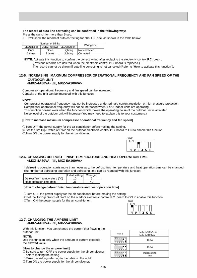
119
12-5. INCREASING MAXIMUM COMPRESSOR OPERATIONAL FREQUENCY AND FAN SPEED OF THE OUTDOOR UNIT
<MXZ-4A80VA- E2 , MXZ-5A100VA>
12-6. CHANGING DEFROST FINISH TEMPERATURE AND HEAT OPERATION TIME <MXZ-4A80VA- E2 , MXZ-5A100VA>
Compressor operational frequency and fan speed can be increased.Capacity of the unit can be improved with this function.
NOTE: Compressor operational frequency may not be increased under primary current restriction or high pressure protection. Compressor operational frequency will not be increased when 1 or 2 indoor units are operating. This function doesn't work when the function which lowers the operating noise of the outdoor unit is activated. Noise level of the outdoor unit will increase (You may need to explain this to your customers.)
[How to increase maximum compressor operational frequency and fan speed]
Turn OFF the power supply for the air conditioner before making the setting. Set the 3rd Dip Switch of SW2 on the outdoor electronic control P.C. board to ON to enable this function. Turn ON the power supply for the air conditioner.
ONSW2
1 2 3 4 5 6
If defrosting operation starts more than necessary, the defrost finish temperature and heat operation time can be changed. The number of defrosting operation and defrosting time can be reduced with this function.
[How to change defrost finish temperature and heat operation time]
Turn OFF the power supply for the air conditioner before making the setting. Set the 1st Dip Switch of SW2 on the outdoor electronic control P.C. board to ON to enable this function. Turn ON the power supply for the air conditioner.
ONSW2
1 2 3 4 5 6
Defrost finish temperature (°C)Heat operation time (min.)
Initial setting1031
Changed540
The record of auto line correcting can be confirmed in the following way:Press the switch for more than 5 sec.LED will show the record of auto correcting for about 30 sec. as shown in the table below:
NOTE: Activate this function to confirm the correct wiring after replacing the electronic control P.C. board. (Previous records are deleted when the electronic control P.C. board is replaced.) The record cannot be shown if auto line correcting is not canceled (Refer to "How to activate this function").
LED1(Red)Once
3 times
LED2(Yellow)Once
3 times
LED3(Green)LightingLighting
Not correctedCorrected
Number of blinks Wiring line
12-7. CHANGING THE AMPERE LIMIT <MXZ-4A80VA- E2 , MXZ-5A100VA>
With this function, you can change the current that flows in the outdoor unit.
[How to change the ampere limit] Be sure to turn OFF the power supply for the air conditioner before making the setting. Make the setting referring to the table on the right. Turn ON the power supply for the air conditioner.
NOTE:Use this function only when the amount of current exceeds the allowed value.
SW 2 MXZ-5A100VAMXZ-4A80VA - E2
ON
10.5A
ON
15.5A
ON Initial settingFull
120
TROUBLESHOOTING13
3. Troubleshooting procedure1) First, check if the OPERATION INDICATOR lamp on the indoor unit is flashing on and off to indicate an abnormality.
To make sure, check how many times the abnormality indication is flashing on and off before starting service work.2) If the electronic control P.C. board seems to be defective, check the copper foil pattern for disconnection and the com-
ponents for bursting and discoloration.3) Refer to 13-2, 13-3 and 13-4.
Lead wiring Housing point
13-1. CAUTIONS ON TROUBLESHOOTING1. Before troubleshooting, check the following:
1) Check the power supply voltage.2) Check the indoor/outdoor connecting wire for miswiring.
2. Take care of the following during servicing1) Before servicing the air conditioner, be sure to turn OFF the unit first with the remote controller, and after confirming
the horizontal vane is closed, turn OFF the breaker and/or disconnect the power plug.2) Be sure to turn OFF the power supply before removing the front panel, the cabinet, the top panel, and the electronic
control P.C. board.3) When removing the electrical parts, be careful of the residual voltage of smoothing capacitor.4) When removing the electronic control P.C. board, hold the edge of the board with care NOT to apply stress on the
components.5) When connecting or disconnecting the connectors, hold the housing of the connector. DO NOT pull the lead wires.
MXZ-2A30VA MXZ-2A40VA MXZ-2A52VA MXZ-3A54VA MXZ-4A71VA MXZ-4A80VAMXZ-5A100VA
13-2. FAILURE MODE RECALL FUNCTIONThis air conditioner can memorize the abnormal condition which has occurred once.Even though LED indication listed on the troubleshooting check table (13-4) disappears, the memorized failure detailscan be recalled.This mode is very useful when the unit needs to be repaired for the abnormality which doesn’t recur.
1. Type of failure mode recall functionThere are 2 types in failure mode recall function as shown below.
Indoor and outdoor unit failure mode recall function With this function, failure mode of indoor unit and a part of failure mode of outdoor unit can be recalled.
The details of outdoor unit failure mode recall function With this function, more detailed failure mode of outdoor unit can be recalled.
Refer to the service manual of indoor unit for how to recall the failure mode and the details of indoor unit failure mode.The outdoor unit failure mode is indicated by the operation indicator lamp on the indoor unit and the LED of outdoor unit.See "13-2.2. Outdoor unit failure mode table".
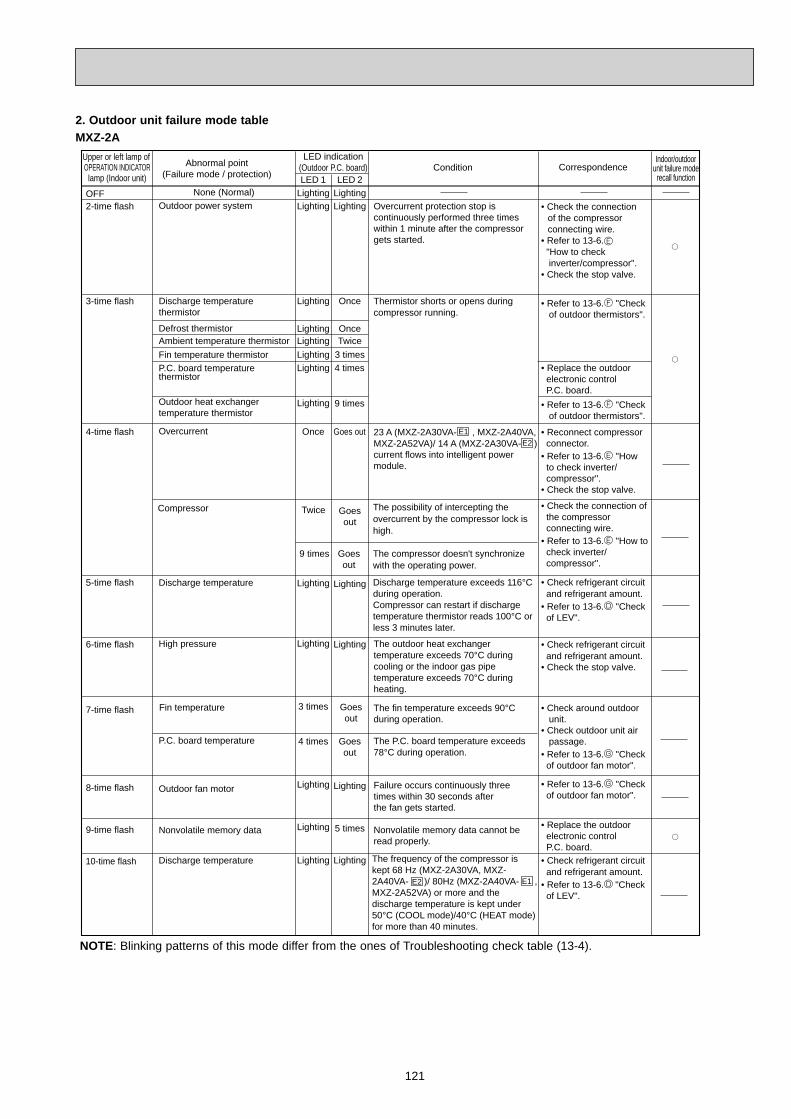
121
E1E2
E2 E1
Abnormal point(Failure mode / protection)
Condition CorrespondenceIndoor/outdoor
unit failure moderecall function
LED indication(Outdoor P.C. board)LED 1 LED 2
Upper or left lamp of OPERATION INDICATORlamp (Indoor unit)
OFF2-time flash
3-time flash
4-time flash
5-time flash
6-time flash
7-time flash
8-time flash
Lighting LightingLighting Lighting
Lighting Once
Lighting OnceLighting TwiceLighting 3 timesLighting 4 times
Lighting 9 times
Once Goes out
Lighting Lighting
Lighting Lighting
3 times Goesout
4 times Goesout
Lighting Lighting
Lighting Lighting
Lighting 5 times9-time flash
10-time flash
• Check the connection of the compressor connecting wire.• Refer to 13-6. "How to check inverter/compressor".• Check the stop valve.
• Replace the outdoor electronic control P.C. board.
• Check refrigerant circuit and refrigerant amount.• Refer to 13-6. "Check of LEV".
• Refer to 13-6. "Check of outdoor fan motor".
• Replace the outdoor electronic control P.C. board.• Check refrigerant circuit and refrigerant amount.• Refer to 13-6. "Check of LEV".
• Reconnect compressor connector.• Refer to 13-6. "How to check inverter/ compressor".• Check the stop valve.
• Check refrigerant circuit and refrigerant amount.• Check the stop valve.
• Check around outdoor unit.• Check outdoor unit air passage.• Refer to 13-6. "Check of outdoor fan motor".
• Refer to 13-6. "Check of outdoor thermistors".
• Refer to 13-6. "Check of outdoor thermistors".
Overcurrent protection stop is continuously performed three times within 1 minute after the compressor gets started.
Thermistor shorts or opens during compressor running.
23 A (MXZ-2A30VA- , MXZ-2A40VA,MXZ-2A52VA)/ 14 A (MXZ-2A30VA- )current flows into intelligent power module.
Discharge temperature exceeds 116°Cduring operation. Compressor can restart if dischargetemperature thermistor reads 100°C or less 3 minutes later.
The outdoor heat exchangertemperature exceeds 70°C during cooling or the indoor gas pipe temperature exceeds 70°C during heating.
The fin temperature exceeds 90°Cduring operation.
The P.C. board temperature exceeds 78°C during operation.
Failure occurs continuously three times within 30 seconds afterthe fan gets started.
Nonvolatile memory data cannot be read properly.
Outdoor power system
Discharge temperaturethermistor
Defrost thermistorAmbient temperature thermistorFin temperature thermistorP.C. board temperaturethermistor
Outdoor heat exchanger temperature thermistor
Overcurrent
Discharge temperature
High pressure
Fin temperature
P.C. board temperature
Outdoor fan motor
Nonvolatile memory data
Discharge temperature
None (Normal)
Compressor Twice
9 times
Goesout
Goesout
The possibility of intercepting the overcurrent by the compressor lock ishigh.
The compressor doesn't synchronizewith the operating power.
• Check the connection of the compressor connecting wire.• Refer to 13-6. "How to check inverter/ compressor".
The frequency of the compressor is kept 68 Hz (MXZ-2A30VA, MXZ- 2A40VA- )/ 80Hz (MXZ-2A40VA- ,MXZ-2A52VA) or more and the discharge temperature is kept under 50°C (COOL mode)/40°C (HEAT mode) for more than 40 minutes.
NOTE: Blinking patterns of this mode differ from the ones of Troubleshooting check table (13-4).
2. Outdoor unit failure mode tableMXZ-2A
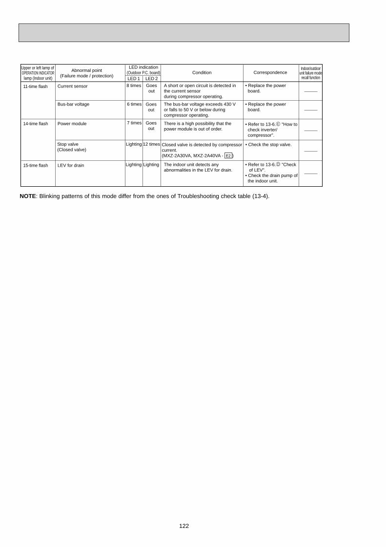
122
11-time flash
15-time flash
• Replace the power board.
• Replace the power board.
A short or open circuit is detected in the current sensorduring compressor operating.
The bus-bar voltage exceeds 430 V or falls to 50 V or below duringcompressor operating.
Current sensor
Bus-bar voltage
LEV for drain
8 times Goesout
6 times Goesout
The indoor unit detects anyabnormalities in the LEV for drain.
Lighting Lighting
14-time flash
• Refer to 13-6. "Check of LEV". • Check the drain pump of the indoor unit.
• Refer to 13-6. "How to check inverter/ compressor".
Power module There is a high possibility that the power module is out of order.
7 times Goesout
12 timesStop valve(Closed valve)
Closed valve is detected by compressor current.(MXZ-2A30VA, MXZ-2A40VA - )
• Check the stop valve.
E2
Lighting
Abnormal point(Failure mode / protection)
Condition CorrespondenceIndoor/outdoor
unit failure moderecall function
LED indication(Outdoor P.C. board)LED 1 LED 2
Upper or left lamp of OPERATION INDICATORlamp (Indoor unit)
NOTE: Blinking patterns of this mode differ from the ones of Troubleshooting check table (13-4).

123
The frequency of the compressor is kept 80Hz or more and the discharge temperature is kept under 50°C (COOL mode)/40°C (HEAT mode)for more than 40 minutes.
Abnormal point(Failure mode / protection)
Condition CorrespondenceIndoor/outdoor
unit failure moderecall function
LED indication(Outdoor P.C. board)LED 1 LED 2
E1
E1
E1 E2
E1 E2
E1 E2E3E3
E3
OFF2-time flash
3-time flash
4-time flash
5-time flash
6-time flash
7-time flash
8-time flash
Lighting LightingLighting Lighting
Lighting Once
Lighting OnceLighting TwiceLighting 3 timesLighting 4 times
Lighting 9 times
Once Goes out
Lighting Lighting
Lighting Lighting
3 times Goesout
4 times Goesout
Lighting Lighting
Lighting Lighting
Lighting 5 times9-time flash
10-time flash
• Replace the outdoor electronic control P.C. board.
• Replace the outdoor electronic control P.C. board.
• Check refrigerant circuit and refrigerant amount.• Refer to 13-6. "Check of LEV".
• Reconnect compressor connector.• Refer to 13-6. "How to check inverter/ compressor".• Check the stop valve.
• Check refrigerant circuit and refrigerant amount.• Check the stop valve.
• Refer to 13-6. "Check of outdoor fan motor".
• Check refrigerant circuit and refrigerant amount.• Refer to 13-6. "Check of LEV".
• Check around outdoor unit.• Check outdoor unit air passage.• Refer to 13-6. "Check of outdoor fan motor".
• Check the connection of the compressor connecting wire.• Refer to 13-6. "How to check inverter/compressor".• Check the stop valve.
• Refer to 13-6. "Check of outdoor thermistors".
• Refer to 13-6. "Check of outdoor thermistors".
Overcurrent protection stop is continuously performed three times within 1 minute after the compressor gets started, or converter protection stop or bus-bar voltage protection stop is continuously performed three times within 3 minutes after start-up.
Thermistor shorts or opens during compressor running.
28A current flows into intelligent power module.
Discharge temperature exceeds 116°Cduring operation. Compressor can restart if dischargetemperature thermistor reads 100°C or less 3 minutes later.High-pressure is detected with the high-pressure switch (HPS) during operation. (MXZ-4A80VA, MXZ-5A100VA)The outdoor heat exchangertemperature exceeds 70°C during cooling or the indoor gas pipe temperature exceeds 70°C during heating.The fin temperature exceeds 89°Cduring operation.
The P.C. board temperature exceeds 73°C (MXZ-3A54VA, MXZ-4A71VA)/ 87°C (MXZ-4A80VA, MXZ-5A100VA)during operation.
Failure occurs continuously three times within 30 seconds after the fan gets started.
Nonvolatile memory data cannot be read properly.
Outdoor power system
Discharge temperaturethermistor
Defrost thermistorAmbient temperature thermistorFin temperature thermistorP.C. board temperaturethermistor
Outdoor heat exchanger temperature thermistor
Overcurrent
Discharge temperature
High pressure
Fin temperature
P.C. board temperature
Outdoor fan motor
Nonvolatile memory data
Discharge temperature
Gas pipe temperaturethermistor A
Lighting 10 times
Gas pipe temperaturethermistor B
Lighting 11 times
Gas pipe temperaturethermistor C
Lighting 12 times
Gas pipe temperaturethermistor D
Lighting 13 times
A short or open circuit is detected in the thermistor during cooling.(A,B,C : MXZ-3A54VA- , , MXZ-4A71VA- , , MXZ-4A80VA- )(D : MXZ-4A71VA- , , MXZ-4A80VA- )
None (Normal)
Upper or left lamp of OPERATION INDICATORlamp (Indoor unit)
NOTE: Blinking patterns of this mode differ from the ones of Troubleshooting check table (13-4).
MXZ-3A/4A/5A

124
Operation start
Check the outdoor unit LED indicator.
Refer to 13-6. "Check of power supply".
• When cooling,dew drops in the non-operatingindoor unit.Check of mispiping
• Indoor unit serial signal errorRefer to 13-6. "How to checkmiswiring andserial signalerror".
• COOL or HEAToperation onlyRefer to 13-6. "Check of R.V. coil".
• When cooling, room does not cool.Refer to 13-6. "How to checkof inverter/compressor".
• When cooling, heat exchanger of non-operating indoor unit frosts.•When heating, non- operating indoor unit gets warm.Refer to 13-6. "Check of LEV".
• When heating,room does not get warm.Refer to 13-6. "How to check of inverter/compressor".Check mispiping, shortage of capacity
Refer to 13-4. "Troubleshooting check table".
Both LED 1 and LED 2 are lighting.
LED 1 or LED 2has blinked.Both LED 1
and LED 2 are OFF.
13-3. INSTRUCTION OF TROUBLESHOOTING• Check the indoor unit with referring to the indoor unit service manual, and confirm whether there is any problem in the indoor unit. Then, check the outdoor unit with referring to this page.
11-time flash
15-time flash
• Check the connecting wire between outdoor electronic control P.C. board and power board.
• Replace the power board.
• Check the connecting wire among electronic control P.C. board, noise filter P.C. board and power board.
• Check the voltage of power supply.• Replace the power board.
• Check the voltage of power supply.• Replace the outdoor electronic control P.C. board.
• Refer to 13-6. "Check of LEV". • Check the drain pump of the indoor unit.
The communication between boards protection stop is continuously performed twice.
Communication error occursbetween the electronic control P.C.board and power board for morethan 10 seconds.
Current sensor protection stop iscontinuously performed twice.
A short or open circuit is detected in the current sensor during compressor operating.
The protection stop of the zero cross detecting circuit is continuously performed 10 times.
Zero cross signal cannot be detected while the compressor is operating.
A failure is detected in the operation of the converter during operation.
The bus-bar voltage exceeds 400 V or falls to 200 V or below during compressor operating.The bus-bar voltage exceeds 400 V (MXZ-3A54VA, MXZ-4A71VA)/ 430 V (MXZ-4A80VA, MXZ-5A100VA)or falls to 50V or below during compressor operating.
Communication errorbetween P.C. boards
Current sensor
Zero cross detecting circuit
Converter
Bus-bar voltage(1)
Bus-bar voltage(2) Even if this protection stop isperformed continuously threetimes, it does not mean theabnormality in outdoor powersystem.
LEV for drain
Lighting 6 times
Lighting 7 times
5 times Goesout
5 times Goesout
5 times
6 times
Goesout
Goesout
The indoor unit detects any abnormalities in the LEV for drain.
Lighting Lighting
Abnormal point(Failure mode / protection)
Condition CorrespondenceIndoor/outdoor
unit failure moderecall function
LED indication(Outdoor P.C. board)LED 1 LED 2
Upper or left lamp of OPERATION INDICATOR
lamp (Indoor unit)
NOTE: Blinking patterns of this mode differ from the ones of "Troubleshooting check table" (13-4).
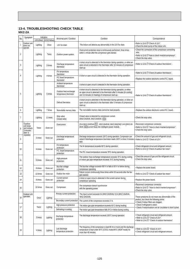
125
13-4. TROUBLESHOOTING CHECK TABLE MXZ-2A
No.
1
2
3
4
5
6
8
9
10
11
12
13
14
15
Symptom
'Outdoorunit stops and restarts 3 minutes later' is repeated.
Primary current protection
Secondary current protection
High-pressure protection
Defrosting in cooling
3 times Lighting Discharge temperatureprotection
4 times LightingLow dischargetemperature protection
• Check refrigerant circuit and refrigerant amount.• Refer to 13-6. "Check of LEV".• Refer to 13-6. "Check of outdoor thermistors".
• Refer to 13-6. "Check of LEV".• Check refrigerant circuit and refrigerant amount.
These symptoms do not mean any abnormality of theproduct, but check the following points.• Check if indoor filters are clogged.• Check if refrigerant is short.• Check if indoor/outdoor unit air circulation is short cycled.Twice Lighting
Once Lighting
The discharge temperature exceeds 100°C during operation.
The frequency of the compressor is kept 80 Hz or more and the discharge temperature is kept under 50°C (COOL mode)/40°C (HEAT mode) for more than 40 minutes.
The input current exceeds 8 A (MXZ-2A30VA)/ 10 A (MXZ-2A40VA, MXZ-2A52VA).
The current of the compressor exceeds 17 A.
The indoor gas pipe temperature exceeds 45°C during heating.
The indoor gas pipe temperature falls 3°C or below during cooling.
Outdoor unit operates.16
17
18
19
7
LED1(Red) LED2(Yellow)
Lighting Twice Outdoor power system
Lighting 3 times Discharge temperaturethermistor
Outdoor heat exchangertemperature thermistor
Defrost thermistor
Lighting 7 times Nonvolatile memory data • Replace the outdoor electronic control P.C. board.
Abnormal point / Condition Correspondence
A short circuit is detected in the thermistor during operation, or when an open circuit is detected in the thermistor after 5 minutes (in cooling) and 10 minutes (in heating) of compressor start-up.
A short circuit is detected in the thermistor during operation, or when an open circuit is detected in the thermistor after 5 minutes of compressor start-up.
• Replace the outdoor electronic control P.C. board.
Indication
Overcurrent protection stop is continuously performed three times within 1 minute after the compressor gets started.
A short circuit is detected in the thermistor during operation, or when an open circuit is detected in the thermistor after 10 minutes of compressor start-up.
Condition
The nonvolatile memory data cannot be read properly.
Fin temperaturethermistorP.C board temperaturethermistor
Lighting 4 times
Ambient temperaturethermistor
A short or open circuit is detected in the thermistor during operation.
A short or open circuit is detected in the thermistor during operation.
5 timesLighting
Overcurrent
3 times Goes out Discharge temperatureprotection
Fin temperatureprotectionP.C. board temperatureprotection
High-pressureprotection
• Replace the power board.Bus-bar voltageprotection
Goes out Outdoor fan motor
8 times Goes outCurrent sensorprotection • Replace the power board.
Goes out Compressor
• Refer to 13-6. "Check of outdoor fan motor".
• Reconnect compressor connector.• Refer to 13-6. "How to check inverter/compressor". • Check the stop valve.
• Check the amount of gas and the refrigerant circuit.• Check the stop valve.
• Check the amount of gas and refrigerant circuit.• Refer to 13-6. "Check of LEV".
• Check refrigerant circuit and refrigerant amount.• Refer to 13-6. "Check of outdoor fan motor".
• Reconnect compressor connector.• Refer to 13-6. "How to check inverter/compressor". • Check the stop valve.
Twice Goes out
4 times Goes out
5 times Goes out
9 times Goes out
23 A (MXZ-2A30VA- , MXZ-2A40VA, MXZ-2A52VA)/ 14 A (MXZ-2A30VA- )current flows into intelligent power module.
The bus-bar voltage exceeds 430 V or falls to 50 V or below during compressor operating.
Discharge temperature exceeds 116°C during operation. Compressor canrestart if discharge temperature thermistor reads 100°C or less 3 minutes later.
The fin temperature exceeds 90°C during operation.
The P.C. board temperature exceeds 78°C during operation.
Failure occurs continuously three times within 30 seconds after the fan gets started.A short or open circuit is detected in the current sensor duringcompressor operating.
The compressor doesn't synchronizewith the operating power.
The outdoor heat exchanger temperature exceeds 70°C during cooling or indoor gas pipe temperature exceeds 70°C during heating.
Outdoor unit does not operate.
Lighting Once LEV for drain
• Check the connection of the compressor connecting wire.• Refer to 13-6. "How to check inverter/compressor". • Check the stop valve.
• Refer to 13-6. "Check of outdoor thermistors".
• Refer to 13-6. "Check of outdoor thermistors".
• Refer to 13-6. "Check of outdoor thermistors".
• Refer to 13-6 "Check of LEV".• Check the drain pump of the indoor unit.The indoor unit detects any abnormality in the LEV for drain.
Lighting 11 times Stop valveClosed valve
Closed valve is detected by compressor current. (MXZ-2A30VA, MXZ-2A40VA - ) • Check the stop valve.
13 times
10 times
E2
E1E2

126
-
-
9 times Lighting Inverter check mode
Lighting Lighting Normal
The unit is operated with emergency operation switch.
-
5 times LightingCooling high-pressureprotection
This symptom does not mean any abnormality of theproduct, but check the following points.• Check if indoor filters are clogged. • Check if refrigerant is short.• Check if indoor/outdoor unit air circulation is short cycled.
The outdoor heat exchanger temperature exceeds 58°C during operation.20
LED1(Red) LED2(Yellow)Abnormal point / Condition CorrespondenceIndication ConditionNo. Symptom
Outdoor unitoperatesnormally.
21
22
Outdoor unit operates.
Display P.C. board(Parts side)
LightingLED1 LED2
The flashing frequency shows the number of times the LED blinks after every 2.5-second OFF.(Example) When the flashing frequency is “2”.
ON
OFF2.5-second OFF 2.5-second OFF
0.5-second ON 0.5-second ON
NOTE 1. The location of LED is illustrated at the right figure. Refer to 13-7.6. 2. LED is lighted during normal operation.
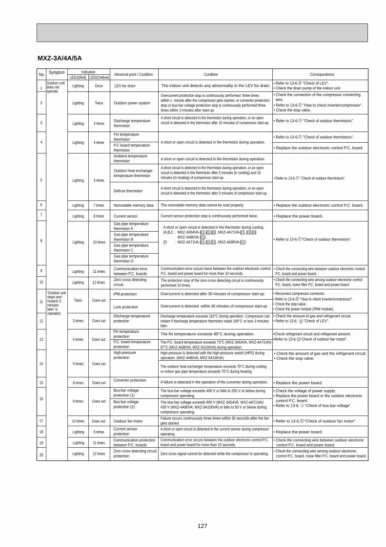
127
MXZ-3A/4A/5A
LED1(Red) LED2(Yellow)
Lighting Twice Outdoor power system
Lighting 3 times Discharge temperaturethermistor
• Refer to 13-6. "Check of outdoor thermistors".
• Refer to 13-6. "Check of outdoor thermistors".
Outdoor heat exchangertemperature thermistor
Defrost thermistor
Lighting 7 times Nonvolatile memory data • Replace the outdoor electronic control P.C. board.
Lighting 8 times Current sensor • Replace the power board.
Lighting 11 times Communication errorbetween P.C. boards
• Check the connecting wire between outdoor electronic control P.C. board and power board.
Lighting 12 times Zero cross detectingcircuit
• Check the connecting wire among outdoor electronic control P.C. board, noise filter P.C. board and power board.
Abnormal point / Condition Correspondence
A short circuit is detected in the thermistor during operation, or an open circuit is detected in the thermistor after 5 minutes (in cooling) and 10 minutes (in heating) of compressor start-up.
A short circuit is detected in the thermistor during operation, or an open circuit is detected in the thermistor after 5 minutes of compressor start-up.
• Replace the outdoor electronic control P.C. board.
Indication
Overcurrent protection stop is continuously performed three times within 1 minute after the compressor gets started, or converter protection stop or bus-bar voltage protection stop is continuously performed three times within 3 minutes after start-up.
A short circuit is detected in the thermistor during operation, or an open circuit is detected in the thermistor after 10 minutes of compressor start-up.
Condition
The nonvolatile memory data cannot be read properly.
Fin temperaturethermistorP.C board temperaturethermistor
Lighting 4 times
Ambient temperaturethermistor
Current sensor protection stop is continuously performed twice.
Communication error occurs twice between the outdoor electronic control P.C. board and power board for more than 10 seconds.
The protection stop of the zero cross detecting circuit is continuouslyperformed 10 times.
A short or open circuit is detected in the thermistor during operation.
A short or open circuit is detected in the thermistor during operation.
5 timesLighting
IPM protection
Lock protection
3 times Goes outDischarge temperatureprotection
Fin temperatureprotectionP.C. board temperatureprotectionHigh-pressureprotection
8 times Goes out Converter protection • Replace the power board.
Bus-bar voltageprotection (1)
• Check the voltage of power supply.• Replace the power board or the outdoor electronic control P.C. board.• Refer to 13-6. “Check of bus-bar voltage”.
Bus-bar voltageprotection (2)
13 times Goes out Outdoor fan motor • Refer to 13-6. "Check of outdoor fan motor".
Lighting 8 timesCurrent sensorprotection • Replace the power board.
Lighting 11 times Communication protectionbetween P.C. boards
• Check the connecting wire between outdoor electronic control P.C. board and power board.
Lighting 12 times Zero cross detecting circuitprotection
• Check the connecting wire among outdoor electronic control P.C. board, noise filter P.C. board and power board.
• Check the amount of gas and the refrigerant circuit.• Check the stop valve.
• Check the amount of gas and refrigerant circuit.• Refer to 13-6. "Check of LEV".
•Check refrigerant circuit and refrigerant amount.•Refer to 13-6. "Check of outdoor fan motor".
• Reconnect compressor connector.• Refer to 13-6. "How to check inverter/compressor". • Check the stop valve.• Check the power module (PAM module).
Twice Goes out
4 times Goes out
5 times Goes out
9 times Goes out
Overcurrent is detected after 30 minutes of compressor start-up.
Overcurrent is detected within 30 minutes of compressor start-up
The bus-bar voltage exceeds 400 V or falls to 200 V or below during compressor operating.The bus-bar voltage exceeds 400 V (MXZ-3A54VA, MXZ-4A71VA)/ 430 V (MXZ-4A80VA, MXZ-5A100VA) or falls to 50 V or below during compressor operating.
Discharge temperature exceeds 116°C during operation. Compressor can restart if discharge temperature thermistor reads 100°C or less 3 minutes later.
The fin temperature exceeds 89°C during operation.
The P.C. board temperature exceeds 73°C (MXZ-3A54VA, MXZ-4A71VA)/ 87°C (MXZ-4A80VA, MXZ-5A100VA) during operation. High-pressure is detected with the high-pressure switch (HPS) during operation. (MXZ-4A80VA, MXZ-5A100VA)
Failure occurs continuously three times within 30 seconds after the fan gets started.A short or open circuit is detected in the current sensor during compressor operating.Communication error occurs between the outdoor electronic control P.C. board and power board for more than 10 seconds.
Zero cross signal cannot be detected while the compressor is operating.
The outdoor heat exchanger temperature exceeds 70°C during cooling or indoor gas pipe temperature exceeds 70°C during heating.
A failure is detected in the operation of the converter during operation.
Outdoor unit does not operate.
Lighting Once LEV for drain
• Check the connection of the compressor connecting wire.• Refer to 13-6. "How to check inverter/compressor". • Check the stop valve.
• Refer to 13-6. "Check of outdoor thermistors".
• Refer to 13-6. "Check of outdoor thermistors".
• Refer to 13-6. "Check of LEV".• Check the drain pump of the indoor unit.The indoor unit detects any abnormality in the LEV for drain.
Lighting 10 times
Gas pipe temperature thermistor D
Gas pipe temperature thermistor AGas pipe temperaturethermistor BGas pipe temperaturethermistor C
A short or open circuit is detected in the thermistor during cooling.(A,B,C : MXZ-3A54VA- , , , MXZ-4A71VA- , , MXZ-4A80VA- )(D : MXZ-4A71VA- , , , MXZ-4A80VA- )
No.
1
2
3
4
5
6
7
8
10
9
11
12
13
14
15
16
17
18
19
20
Symptom
'Outdoor unit stops and restarts 3 minuteslater' is repeated.
E1E1
E2 E1 E2 E3E3
E1 E2 E1E3
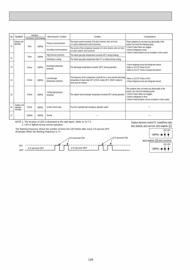
128
Primary current protection
Secondary current protection
High-pressure protection
Defrosting in cooling
3 times Lighting Discharge temperatureprotection
4 times LightingLow dischargetemperature protection
• Check refrigerant circuit and refrigerant amount.• Refer to 13-6. "Check of LEV".• Refer to 13-6. "Check of outdoor thermistors".
• Refer to 13-6. "Check of LEV".• Check refrigerant circuit and refrigerant amount.
5 times LightingCooling high-pressureprotection
This symptom does not mean any abnormality of theproduct, but check the following points.• Check if indoor filters are clogged. • Check if refrigerant is short.• Check if indoor/outdoor unit air circulation is short cycled.
-
-
These symptoms do not mean any abnormality of theproduct, but check the following points.• Check if indoor filters are clogged.• Check if refrigerant is short.• Check if indoor/outdoor unit air circulation is short cycled.
Twice Lighting
Once Lighting
The outdoor heat exchanger temperature exceeds 58°C during operation.
9 times Lighting Inverter check mode
Lighting Lighting Normal
The unit is operated with emergency operation switch.
-
The input current exceeds 15 A (MXZ-3A54VA, MXZ-4A71VA)/ 17 A (MXZ-4A80VA)/18 A (MXZ-5A100VA).The current of the compressor exceeds 12 A (MXZ-3A54VA, MXZ-4A71VA)/ 10 A (MXZ-4A80VA, MXZ-5A100VA).
The indoor gas pipe temperature exceeds 45°C during heating.
The indoor gas pipe temperature falls 3°C or below during cooling.
The discharge temperature exceeds 100°C during operation.
The frequency of the compressor is kept 80 Hz or more and the discharge temperature is kept under 50°C (COOL mode) /40°C (HEAT mode) for more than 40 minutes.
LED2 LED1
Outdoor electronic control P.C. board(Parts side)
Lighting
LED1 LED2
Lighting
MXZ-3A54VA, MXZ-4A71VA, MXZ-4A80VA- E1
MXZ-4A80VA- E2 , MXZ-5A100VA
LED1(Red) LED2(Yellow)Abnormal point / Condition CorrespondenceIndication ConditionNo.
21
22
23
24
25
26
27
Outdoor unit operates normally.
Outdoor unit operates.
Symptom
The flashing frequency shows the number of times the LED blinks after every 2.5-second OFF.(Example) When the flashing frequency is “2”.
ON
OFF2.5-second OFF 2.5-second OFF
0.5-second ON 0.5-second ON
NOTE 1. The location of LED is illustrated at the right figure. Refer to 13-7.2. 2. LED is lighted during normal operation.

129
Defrost thermistor (RT61)
Fin temperature thermistor (RT64)
Ambient temperature thermistor (RT65)
Outdoor heat exchanger temperature thermistor (RT68)
Gas pipe temperature thermistor (RT6A~D)MXZ-3A54VA- E1 , E2 , E3MXZ-4A71VA- E1 , E2 , E3MXZ-4A80VA- E1
2A40VA- E1
2A52VA
Discharge temperature thermistor (RT62)
WHT - REDRED - ORN
Measure the resistance using a tester. (Part temperature : -10°C ~ 40°C)
37.4 ~ 53.9
Part name Check method and criterion
Measure the resistance between terminals using a tester.(Winding temperature : -10°C ~ 40°C)
CompressorW
UVWHT
RED
BLK
Measure the resistance between lead wires using a tester.(Part temperature : -10°C ~ 40°C)
Outdoor fan motor
R.V. coil
Measure the resistance using a tester. (Part temperature : -10°C ~ 40°C)Linear expansion valve
LEV
WHT
RED
YLW BRN
ORN
BLU
Color of lead wire Normal
YLW - BRNBRN - BLU
URED
WHT
BLK
V
W
(W)
(V)
(U)
Normal (Each phase)
13.4 ~ 16.4
High pressure switch (HPS) MXZ-4A80/5A100
Pressure Normal
HPS3.7 0.15 MPa4.8 MPa Open
Close+ 0.05- 0.1
13-5. TROUBLE CRITERION OF MAIN PARTS
MXZ-2A30VA MXZ-2A40VA MXZ-2A52VA MXZ-3A54VA MXZ-4A71VA MXZ-4A80VAMXZ-5A100VA
MXZ-3A/4A/5A
12 ~ 16
MXZ-2A
Measure the resistance with a tester.
Refer to 13-7. “Test point diagram and voltage”, 1. “Inverter P.C. board” , 2. “Outdoor electronic control P.C. board” or 5. “Outdoor Power board”, for the chart of thermistor.
Measure the resistance with a tester.Before measurement, hold the thermistor with your hands to warm it up.
Refer to 13-7. “Test point diagram and voltage”, 1. “Inverter P.C. board” or 2. “Outdoor electronic control P.C. board”, for the chart of thermistor.
2 3W
UV
1
WHT RED BLK
MXZ-3A/4A/5AMXZ-2A
Normal (Each phase)2A30VA2A40VA- E2
1.49 ~ 1.84 0.56 ~ 0.69
3A54VA - E1 , E2 , E3
4A71VA - E1 , E2 , E3
0.39 ~ 0.49
4A80VA5A100VA
1.29 ~ 1.49
3A54VA - E4 , E5 , E6 , E7
4A71VA - E4 , E5 , E6 , E7
0.86 ~ 1.06
Normal (Each phase)
1.26 k ~ 1.62 k 1.2 k ~ 1.56 k
Other modelsMXZ-3A54VA - E4 , E5 , E6 , E7MXZ-4A71VA - E4 , E5 , E6 , E7
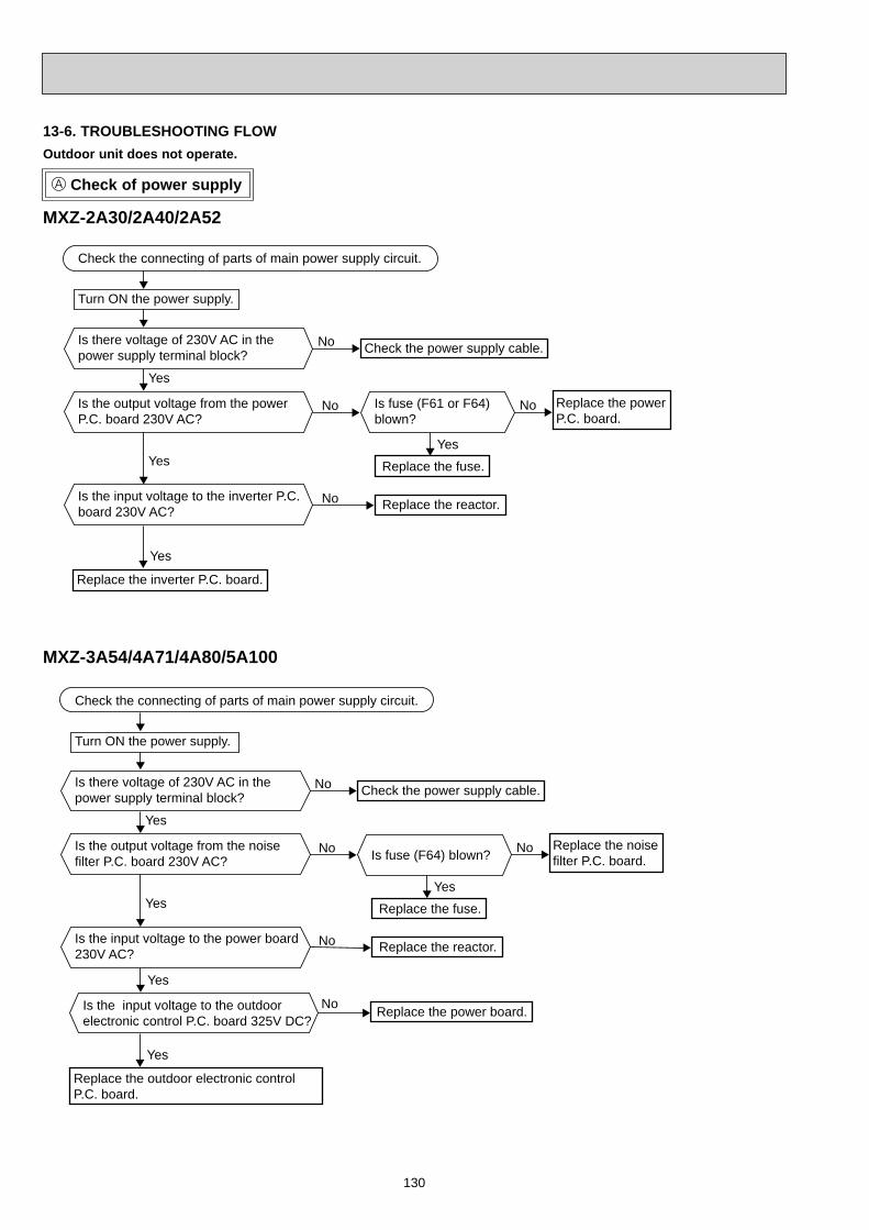
130
Check of power supply
Outdoor unit does not operate.
Turn ON the power supply.
No
Yes
Yes
No No
Yes
No
Yes
Yes
No Replace the power board.
Check the connecting of parts of main power supply circuit.
Is there voltage of 230V AC in the power supply terminal block?
Is the output voltage from the noisefilter P.C. board 230V AC?
Is the input voltage to the outdoor electronic control P.C. board 325V DC?
Check the power supply cable.
Replace the outdoor electronic control P.C. board.
Replace the noise filter P.C. board.Is fuse (F64) blown?
Is the input voltage to the power board230V AC?
Replace the fuse.
Replace the reactor.
13-6. TROUBLESHOOTING FLOW
Turn ON the power supply.
No
Yes
Yes
No No
Yes
No
Yes
Check the connecting of parts of main power supply circuit.
Is there voltage of 230V AC in the power supply terminal block?
Is the output voltage from the powerP.C. board 230V AC?
Check the power supply cable.
Replace the inverter P.C. board.
Replace the power P.C. board.
Is fuse (F61 or F64) blown?
Is the input voltage to the inverter P.C.board 230V AC?
Replace the fuse.
Replace the reactor.
MXZ-2A30/2A40/2A52
MXZ-3A54/4A71/4A80/5A100
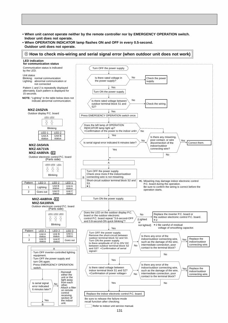
131
Is there rated voltage in the power supply?
Is there any miswiring, poor contact, or wire disconnection of the indoor/outdoor connecting wire?
1. Miswiring may damage indoor electronic control P.C. board during the operation. Be sure to confirm the wiring is correct before the operation starts.
(Lighted or not lighted)
No
Yes
NoYes
Yes
No
Yes
No
Yes
Be sure to release the failure-moderecall function after checking.
No
No
Yes
No
Yes
Yes
Yes
No
Yes
Refer to indoor unit service manual.
Turn OFF the power supply.
Turn ON the power supply.
Is there rated voltage betweenoutdoor terminal block S1 andS2?
Does the left lamp of OPERATIONINDICATOR lamp light up? <Confirmation of the power to the indoor unit>
Press EMERGENCY OPERATION switch once.
Check the powersupply.
A
Turn OFF the power supply.Check once more if the indoor/outdoorconnecting wire is not miswiring.Short-circuit outdoor terminal block S2 andS3.
1
B
Turn ON the power supply.
Check the wiring.
Correct them.
Turn OFF the power supply.Remove the short-circuit betweenoutdoor terminal block S2 and S3.Turn ON the power supply.Is there amplitude of 10 to 20V DCbetween outdoor terminal block S2and S3? <Confirmation of serialsignal>
Is there rated voltage between indoor terminal block S1 and S2?<Confirmation of power voltage>
Replace the indoor electronic control P.C. board.
2 Be careful of residual voltage of smoothing capacitor.
Replace the inverter P.C. board or the outdoor electronic control P.C. board. 2
Is there any error of theindoor/outdoor connecting wire,such as the damage of the wire,intermediate connection, poorcontact to the terminal block?
Is there any error of theindoor/outdoor connecting wire,such as the damage of the wire,intermediate connection, poorcontact to the terminal block?
No
Replace theindoor/outdoorconnecting wire.
Replace theindoor/outdoorconnecting wire.
Is serial signalerror indicated 6 minutes later?
Yes
No
· Turn OFF inverter-controlled lighting equipment.
· Turn OFF the power supply and turn ON again.
· Press EMERGENCY OPERATION switch.
B
· Reinstall either the unit or the light away from each other.
· Attach a filter on remote controlreceivingsection of the indoor unit.
A
Is serial signal error indicated 6 minutes later?
No
Does the LED on the outdoor display P.C.board or the outdoor electronic control P.C. board repeat "3.6-second-OFF and 0.8-second-ON quick blinking"?
LED indication for communication statusCommunication status is indicated by the LED.
Blinking: normal communicationLighting: abnormal communication or not connectedPattern 1 and 2 is repeatedly displayed alternately. Each pattern is displayed for 15 seconds.
NOTE: "Lighting" in the table below does not indicate abnormal communication.
Outdoor electronic control P.C. board
Blinking
LED 3
Lighting
Goes out
LED 1LED 2
(Parts side)
LED3 LED2 LED1
Outdoor electronic control P.C. board
Blinking
(Parts side)
LED1 LED2 LED3
Outdoor display P.C. boardMXZ-2A52VA
Blinking
LED1 LED2
LED 1 LED 2
MXZ-3A54VAMXZ-4A71VAMXZ-4A80VA - E1
MXZ-4A80VA - E2MXZ-5A100VA
Unit status
Pattern
1
2
Unit BstatusUnit Dstatus
Unit AstatusUnit Cstatus
LED 1 LED 3LED 2Pattern
1
2
Unit Bstatus
Unit Dstatus
Unit Astatus
Unit Cstatus
Unit Estatus Goes out
Unit Astatus
Unit Bstatus
How to check mis-wiring and serial signal error (when outdoor unit does not work)
• When unit cannot operate neither by the remote controller nor by EMERGENCY OPERATION switch. Indoor unit does not operate.• When OPERATION INDICATOR lamp flashes ON and OFF in every 0.5-second. Outdoor unit does not operate.

132
Check of R.V. coil
No
Yes
No
Yes
No
Yes
No
Yes
No
Yes
1. Disconnect the lead wire leading to the compressor.2. 3 minutes after turning ON the power supply, start EMERGENCY OPERATION in HEAT mode.
Is there voltage of 230V AC between pin1 and pin 2 at connector CN912?
Turn OFF the power supply of indoor and outdoor unit.
1. Turn OFF the power supply of indoor and outdoor unit, and disconnect the connector CN933 or CN781.2. 3 minutes after turning ON the power supply, start EMERGENCY OPERATION in HEAT mode.
Replace the 4-way valve. Replace the power P.C. board or the noise filter P.C. board.
Replace the R.V. coil.
Is there voltage 12V DC between the connector CN933pin 1 (+) and pin 3 (-) or the connector CN781 pin 5 (+) and pin 3 (-) ?
Replace the inverter P.C.board or the electronic control P.C. board.
Disconnect the connector CN912. Is there normal resistance to R.V. coil?(Refer to 13-5.)
1. Disconnect the lead wire leading to the compressor.2. 3 minutes after turning ON the power supply, start EMERGENCY OPERATION in COOL mode.
Is there voltage of 230V AC between pin1 and pin 2 at connector CN912?
1. Turn OFF the power supply of the indoor and the outdoor unit, and disconnect the connector CN933 or CN781.2. 3 minutes after turning ON the power supply, start EMERGENCY OPERATION in COOL mode.
Replace the 4-way valve.
Replace the power P.C.board or the noise filter P.C. board.
Is there voltage 12V DC between the connector CN933pin 1 (+) and pin 3 (-) or the connector CN781 pin 5 (+) and pin 3 (-) ?
Replace the inverter P.C. board or the outdoor electronic control P.C. board.
If the connector CN912 is not connected or R.V. coil is open, voltage occurs between terminals even when the control is OFF.
• When heating operation does not work.
• When cooling operation does not work.
The cooling operation or heating operation does not operate.
Power P.C. board
Inverter P.C. board
CN912CN781
CN933
Noise filter P.C. boardOutdoor electronic controlP.C. board
MXZ-2A MXZ-3A/4A/5A
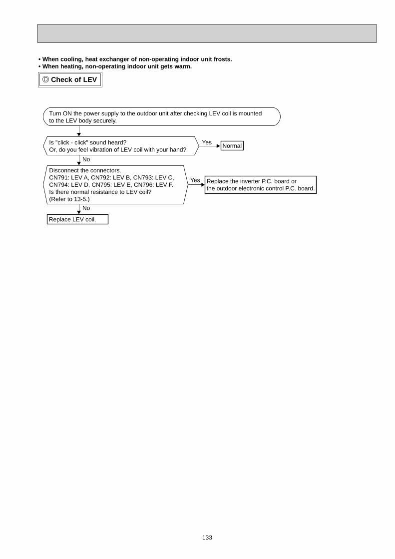
133
Check of LEV
No
Yes
No
Yes
Turn ON the power supply to the outdoor unit after checking LEV coil is mounted to the LEV body securely.
Is "click - click" sound heard?Or, do you feel vibration of LEV coil with your hand?
Disconnect the connectors.CN791: LEV A, CN792: LEV B, CN793: LEV C,CN794: LEV D, CN795: LEV E, CN796: LEV F. Is there normal resistance to LEV coil?(Refer to 13-5.)
Normal
Replace the inverter P.C. board or the outdoor electronic control P.C. board.
Replace LEV coil.
• When cooling, heat exchanger of non-operating indoor unit frosts.• When heating, non-operating indoor unit gets warm.
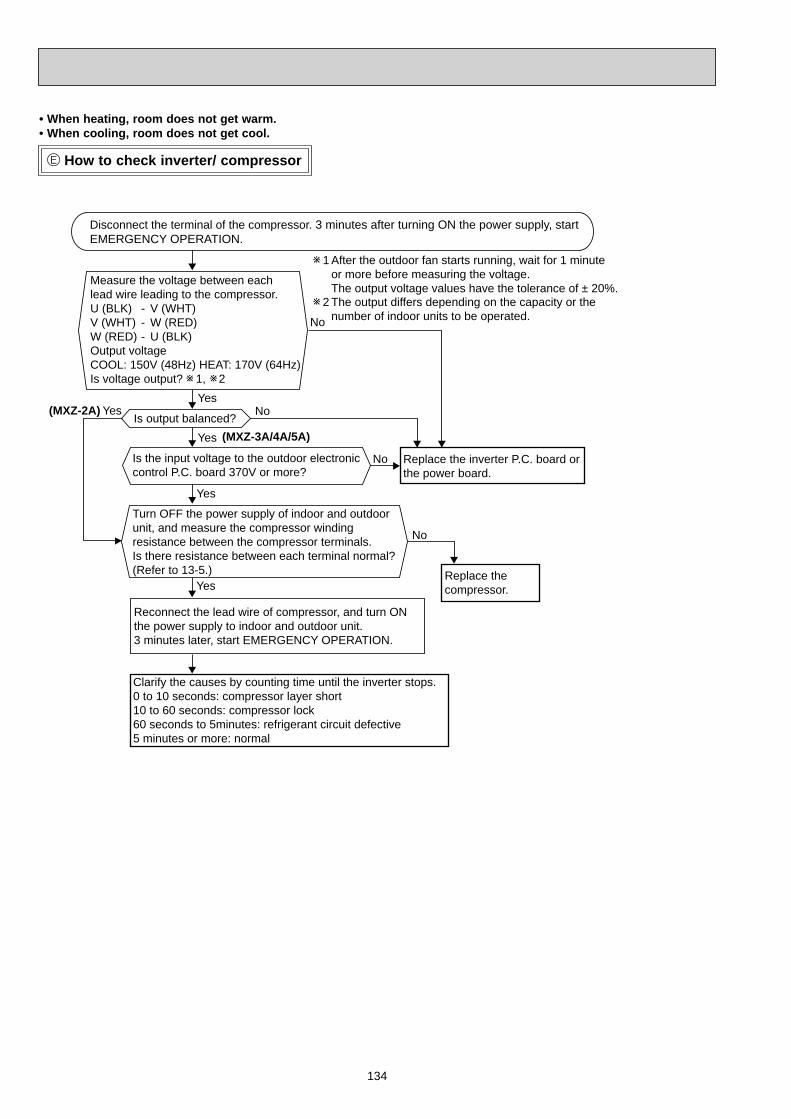
134
How to check inverter/ compressor
• When heating, room does not get warm.• When cooling, room does not get cool.
No
No
Yes
Yes
Yes
No
Yes
No
(MXZ-3A/4A/5A)
Yes(MXZ-2A)
Disconnect the terminal of the compressor. 3 minutes after turning ON the power supply, start EMERGENCY OPERATION.
Is output balanced?
Clarify the causes by counting time until the inverter stops.0 to 10 seconds: compressor layer short 10 to 60 seconds: compressor lock60 seconds to 5minutes: refrigerant circuit defective5 minutes or more: normal
Measure the voltage between each lead wire leading to the compressor.U (BLK) - V (WHT) V (WHT) - W (RED) W (RED) - U (BLK) Output voltageCOOL: 150V (48Hz) HEAT: 170V (64Hz)Is voltage output? 1, 2
Turn OFF the power supply of indoor and outdoor unit, and measure the compressor winding resistance between the compressor terminals.Is there resistance between each terminal normal?(Refer to 13-5.)
Is the input voltage to the outdoor electronic control P.C. board 370V or more?
Reconnect the lead wire of compressor, and turn ON the power supply to indoor and outdoor unit. 3 minutes later, start EMERGENCY OPERATION.
Replace the compressor.
Replace the inverter P.C. board or the power board.
1 After the outdoor fan starts running, wait for 1 minute or more before measuring the voltage. The output voltage values have the tolerance of ± 20%. 2 The output differs depending on the capacity or the number of indoor units to be operated.

135
Check of outdoor thermistors
• When thermistor is abnormal.
Disconnect the connector in the following table and measure the resistance of the thermistor to check whether the thermistor is normal or not. (Refer to 13-7.)
Does the unit operate 10 minutes or more without showing thermistor abnormality?
Replace the thermistor except RT64. In case that RT64 is abnormal, replace the inverter P.C. board or the outdoor power board since RT64is combined with the inverter P.C. board or the outdoor power board.
Normal
Replace the inverter P.C. board, the outdoor electronic control P.C. board, or the outdoor power board.
Normal
Yes
No
Abnormal
Reconnect the connector in the following table and disconnect the lead wire leading to the compressor. 3 minutes after turning ON the power supply, start EMERGENCY OPERATION.
ThermistorDefrostDischarge temperatureOutdoor heat exchanger temperature Fin temperatureAmbient temperature
SymbolRT61RT62RT68RT64RT65
Connector, Pin No.Between CN661 pin1 and pin2Between CN661 pin3 and pin4Between CN661 pin5 and pin6 Between CN662 pin1 and pin2Between CN663 pin1 and pin2
Inverter P.C. board
Board
ThermistorDefrostDischarge temperatureOutdoor heat exchanger temperature Gas pipe temperature (Unit A) Gas pipe temperature (Unit B)Gas pipe temperature (Unit C)Gas pipe temperature (Unit D)Ambient temperatureFin temperature
SymbolRT61RT62RT68RT6ART6BRT6CRT6DRT65RT64
Connector, Pin No.Between CN661 pin1 and pin2Between CN661 pin3 and pin4Between CN661 pin7 and pin8 Between CN662 pin1 and pin2Between CN662 pin3 and pin4Between CN662 pin5 and pin6Between CN662 pin7 and pin8Between CN663 pin1 and pin2Between CN3 pin1 and pin2
Outdoor electronic control P.C. board
Outdoor power board
Board
Except MXZ-3A54VA- , , , , MXZ-4A71VA- , , , , MXZ-4A80VA- and MXZ-5A100VA.E4 E5E5 E6 E7 E6 E7E4 E2
MXZ-3A54/4A71/4A80/5A100
MXZ-2A30/2A40/2A52

136
Check of outdoor fan motor
• Fan motor does not operate or stops operating shortly after starting the operation.
Yes
Yes
YesNo
(Fixed to either 5V or 0V DC)
No
No
Disconnect CN932 from the inverter P.C. board or the outdoor electronic control P.C. board, and measure the resistance of the outdoor fan motor.
Turn ON the power supply.Rotate the outdoor fan motor manually and measure the voltage of CN931.Between (+) and (-)Between (+) and (-)Between (+) and (-)
Is the resistance of outdoor fan motor normal? (Refer to 13-5.)
Does the outdoor fan motor rotate smoothly?
Does the voltage between each terminal become 5V DC and 0V DCrepeatedly?
Replace the outdoor fan motor. Replace the inverter P.C. board or the outdoor electronic control P.C. board.

137
Check of HPS
Infinity
0Ω
Yes
No
1. Disconnect the connector CN681 in the electronic control P.C. board.2. Check the resistance of HPS 1 minute after the outdoor unit power supply was turned OFF.
Check the resistance between each terminal.
Reconnect CN681.Turn ON the power supply to the indoor and outdoor unit.3 minutes later, start EMERGENCY OPERATION.
Is HPS protection displayed immediately after compressor starts?
Replace HPS.
Replace the electronic control P.C. board.
Normal
The other cases Indoor unit does not operate. (different operating models in multi system)• When you try to run two indoor units simultaneously, one for cooling and the other for heating, the unit which transmits signal
to the outdoor unit first decides the operation mode. • When the above situation occurs, set all the indoor units to the same mode, turn OFF the indoor units, then turn them back
ON.• Though the top of the indoor unit sometimes gets warm, this does not mean malfunction. The reason is that the refrigerant
gas continuously flows into the indoor unit even while it is not operating.
• When the operation frequency does not go up from lowest frequency.
MXZ-4A80VA/5A100VA
Check of bus-bar voltage
MXZ-3A/4A/5A •Check the voltage of power supply. •Confi rm outdoor unit failure mode recall function. (Refer to 13-2.2.)
Blink 5 times
Confi rm LED1 indication lamp on the outdoor electronic control P.C. board.
Replace the power board.
Blink 9 times
Replace the outdoor elec-tronic control P.C. board.
Turn OFF power supply before removing P.C. board.
Confi rm LED1 indication lamp on the outdoor electronic con-trol P.C. board.
Turn ON power supply. Start operation.
Blink 6 times
Replace the outdoor elec-tronic control P.C. board.
Lighting
Replace the outdoor elec-tronic control P.C. board.
Blink 9 times
Replace the power board.
Confi rm LED1 indication lamp on the outdoor electronic con-trol P.C. board.
Turn ON power supply. Start operation.
NormalLighting Lighting
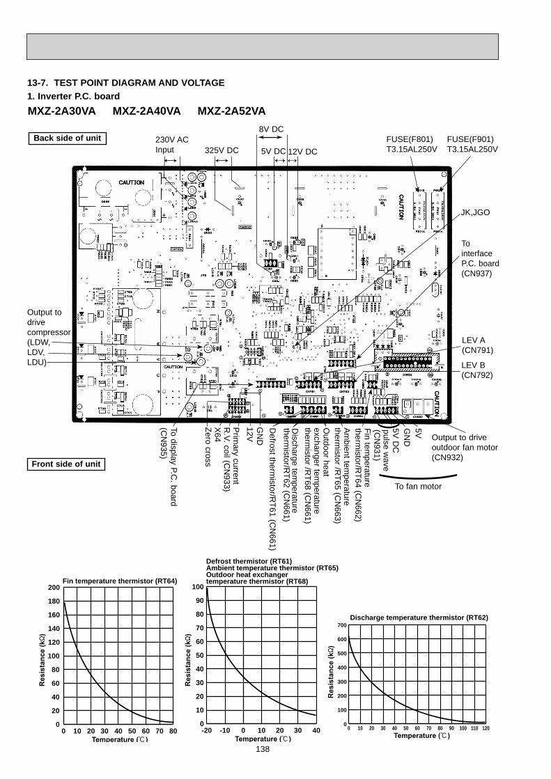
138
Back side of unit
-20 -10 0 10 20 30 400
10
20
30
40
50
60
70
80
90
100
Defrost thermistor (RT61)Ambient temperature thermistor (RT65)Outdoor heat exchangertemperature thermistor (RT68)
Discharge temperature thermistor (RT62)
0 10 20 30 40 50 60 70 80 90 100 110 1200
100
200
300
400
500
600
700
0 10 20 30 40 50 60 70 800
20
40
60
80
100
120
140
160
180
200Fin temperature thermistor (RT64)
Output to drive outdoor fan motor(CN932)
Fin temperature
thermistor/R
T64 (CN
662)A
mbient tem
perature therm
istor /RT65 (C
N663)
Discharge tem
perature therm
istor/RT62 (C
N661)
Defrost therm
istor/RT61 (C
N661)
230V ACInput
Front side of unit
325V DC
8V DC5V
Output to drivecompressor(LDW,LDV,LDU)
JK,JGO
1. Inverter P.C. boardMXZ-2A30VA MXZ-2A40VA MXZ-2A52VA
13-7. TEST POINT DIAGRAM AND VOLTAGE
5V DC 12V DCFUSE(F801)T3.15AL250V
FUSE(F901)T3.15AL250V
To interfaceP.C. board(CN937)
LEV A(CN791)
LEV B(CN792)
GN
D5V
DC
pulse wave
(CN
931)
To fan motor
(Outdoor heat
exchanger temperature
thermistor /R
T68 (CN
661)
(GN
D12VP
rimary current
R.V. coil (C
N933)
X64
Zero cross
To display P.C. board
(CN
935)

139
0 10 20 30 40 50 60 70 80 90 100 110 120
700
600
500
400
300
200
100
0
Res
ista
nce
(kΩ
)
Temperature (°C)
Discharge temperature thermistor (RT62)
-20 -10 0 10 20 30 40
100
90
80
70
60
50
40
30
20
10
0
Defrost thermistor (RT61)Ambient temperature thermistor (RT65)Gas pipe temperature thermistor (RT6A, 6B, 6C, 6D)(Except MXZ-3A54VA- E4 , E5 , E6 , E7 and MXZ-4A71VA- E4 , E5 , E6 , E7 .)Outdoor heat exchanger temperature thermistor (RT68)
Temperature (°C)
Res
ista
nce
(kΩ
)LED 1
LED 2
Bus-bar voltageCN801
325~370 V DCInput
( (
(
LEV
Room
A
(
12V D
Cpulse w
ave
(
LEV
Room
B
(
12V D
Cpulse w
ave
(LE
V R
oom
C(
12V D
Cpulse w
ave
(
LEV
Room
D
(
12V D
Cpulse w
ave
(High pressure switch
(Gas pipe D thermistor (RT6D)
(Gas pipe C thermistor (RT6C)
(Gas pipe B thermistor (RT6B)
(Gas pipe A thermistor (RT6A)
CN
93220-90V
AC GN
D5V
5V D
Cpulse w
ave
( To fanm
otor
Defrost therm
istor (RT61)
Discharge tem
perature thermistor (R
T62)
Outdoor heat exchanger
temperature therm
istor (RT68) ( ((+)
(–)(+)
Rush current relay (–)R
.V. coil (–)( 12V
DC
15V15V
CN
931
(+)(–)
(
CN
661
CN
701S
ignal transmission
(To power board)
5V D
C pulse w
ave
(+)
(–)
(G
ND
CN
702S
ignal reception(From
power board)
5V D
C pulse w
ave
GND (power board)
CN
781
LEV
E ((+)
(–) ((+)
(–) ((+)
(–) ((+)
(–) ( CN
791
CN
792
CN
793
CN
794
CN
681 MXZ-4A
80VA
CN
662( ( (
F801 FUSE
T3.15AL250V
LED 3
(A
mbient tem
peraturetherm
istor (RT65)
CN
663
Serial signal Room D12~24V DC
Serial signal Room C12~24V DC
Serial signal Room B12~24V DC
Serial signal Room A12~24V DC
CN604
CN603
CN602
CN601
230V AC
Input
SW1
CN
79512V
DC
pulse wave
2. Outdoor electronic control P.C. boardMXZ-3A54VA MXZ-4A71VA MXZ-4A80VA - E1
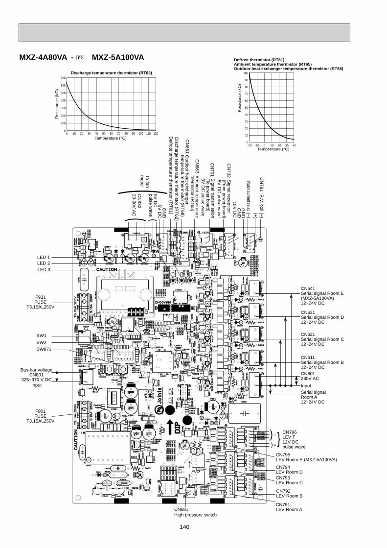
140
0 10 20 30 40 50 60 70 80 90 100 110 120
700
600
500
400
300
200
100
0
Res
ista
nce
(kΩ
)
Temperature (°C)
Discharge temperature thermistor (RT62)
-20 -10 0 10 20 30 40
100
90
80
70
60
50
40
30
20
10
0
Res
ista
nce
(kΩ
)
Temperature (°C)
Defrost thermistor (RT61)Ambient temperature thermistor (RT65)Outdoor heat exchanger temperature thermistor (RT68)
MXZ-4A80VA - E2 MXZ-5A100VA
LED 1LED 2
F931FUSE
T3.15AL250V
(C
N932
20-90V A
C
GN
D5V
DC
5V D
Cpulse w
ave
( To fanm
otor
(+)Rush current relay (–)
R.V. coil (–)
CN
781
CN
663
CN
701
CN
702
CN
661
CN681High pressure switch
(
Bus-bar voltageCN801
325~370 V DCInput
LED 3
Serial signal Room A12~24V DC
CN631Serial signal Room D12~24V DC
CN641Serial signal Room E(MXZ-5A100VA)12~24V DC
CN621Serial signal Room C12~24V DC
CN611Serial signal Room B12~24V DCCN601230V ACInput
SW1SW2SW871
F801FUSE
T3.15AL250V
CN791LEV Room A
CN792LEV Room B
CN794LEV Room D
CN795LEV Room E (MXZ-5A100VA)
CN793LEV Room C
((
+
{CN796LEV F12V DCpulse wave
Defrost tem
perature thermistor (R
T61)D
ischarge temperature therm
istor (RT62)
Outdoor heat exchanger
temperature therm
istor (RT68)
Am
bient temperature
thermistor (R
T65)
Signal transm
ission(To pow
er board)5V
DC
pulse wave
Signal reception
(From pow
er board)5V
DC
pulse wave
GN
DG
ND
15V D
C
–

141
{CN912R.V. coil 230V AC
230V ACInput
230V ACOutput
{
CN901To electroniccontrol P.C. board
MXZ-3A54VA - E1 , E2 , E3 , E4 MXZ-4A71VA - E1 , E2 , E3 , E4 MXZ-4A80VA - E1
F64 FUSET2AL250V
F911 FUSET1AL250V
3. Noise filter P.C. board
CN902To powerboard {
CN903To powerboard
{CN61230V AC Output
NR64 VARISTOR
230V ACOutput
F64 FUSET2AL250V
{
{
CN901To electroniccontrol P.C. board
CN912R.V. coil230V AC
{ CN902To powerboard
CN903To powerboard
230V ACInput
F65FUSET6.3AL250V
MXZ-3A54VA - E5 , E6 , E7 MXZ-4A71VA - E5 , E6 , E7
CN61230V AC Output

142
R.V.coil(CN912)230V AC
Back side of unit
MXZ-2A30VA MXZ-2A40VA MXZ-2A52VAFront side of unit
To inverter P.C.board (CN934)
F61 (FUSE)T20AL250V
4. Power P.C. board
FUSE (F64)T3.15AL250V
230V ACOutput
230V ACInput
GND
12V R.V.coil Zero cross
X64 Primary current(
MXZ-4A80VA - E2 MXZ-5A100VA
230V ACOutput
F64 FUSET2AL250V
{ {
CN901To electroniccontrol P.C. board
CN912R.V. coil230V AC
{
CN902To powerboard
CN903To powerboard
230V ACInput
F65FUSET6.3AL250V
CN61230V ACOutput

143
MXZ-3A54VA MXZ-4A71VA MXZ-4A80VA MXZ-5A100VA5. Outdoor Power board
325-370V DCOutput (Red)
(White)
Connect to the compressorVoltage among phases: 5V to 180V
Connect to the earth
CN5Primary current detection(Connect to the noise filter)
CN2Connect to the controller board(+)1-5(–): Signal transmission (To electronic control P.C. board) 5V DC pulse wave(+)2-5(–): Zero cross signal 3-4 : Not used(+)6-5(–): 15V(+)7-5(–): 15V
(+)
(–)
Signal reception (From electronic control P.C. board) 5V DC pulse wave
)
CN3Fin temperature thermistor RT64
1
3
0 10 20 30 40 50 60 70 80
200
180
160
140
120
100
80
60
40
20
0
Res
ista
nce
(kΩ
)
Temperature (°C)
Fin temperature thermistor (RT64)
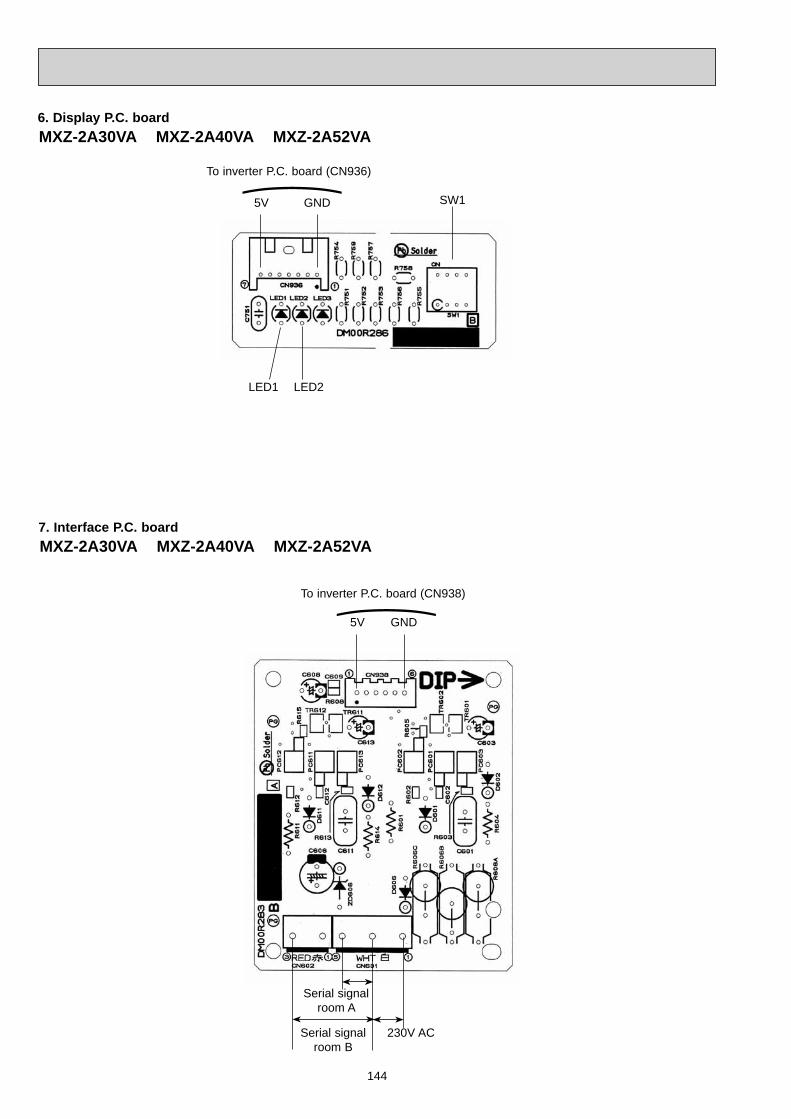
144
MXZ-2A30VA MXZ-2A40VA MXZ-2A52VA6. Display P.C. board
MXZ-2A30VA MXZ-2A40VA MXZ-2A52VA7. Interface P.C. board
SW1GND5V
LED2LED1
GND5V
Serial signal room A
Serial signal room B
230V AC
To inverter P.C. board (CN936))
To inverter P.C. board (CN938))
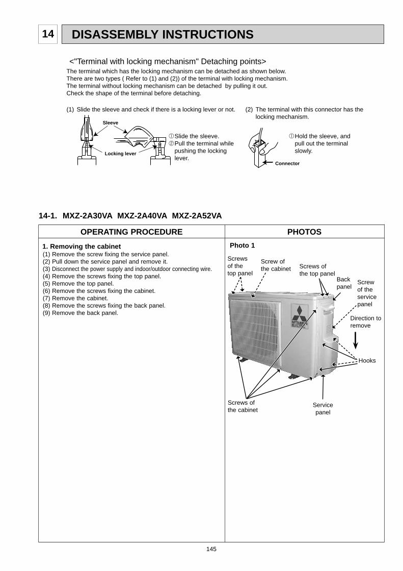
145
DISASSEMBLY INSTRUCTIONS14
OPERATING PROCEDURE PHOTOSPhoto 11. Removing the cabinet
(1) Remove the screw fixing the service panel.(2) Pull down the service panel and remove it.(3) Disconnect the power supply and indoor/outdoor connecting wire.(4) Remove the screws fixing the top panel.(5) Remove the top panel.(6) Remove the screws fixing the cabinet.(7) Remove the cabinet.(8) Remove the screws fixing the back panel.(9) Remove the back panel.
(1) Slide the sleeve and check if there is a locking lever or not. (2) The terminal with this connector has the locking mechanism.
Slide the sleeve. Pull the terminal while pushing the locking lever.
Hold the sleeve, and pull out the terminal slowly.
The terminal which has the locking mechanism can be detached as shown below.There are two types ( Refer to (1) and (2)) of the terminal with locking mechanism.The terminal without locking mechanism can be detached by pulling it out.Check the shape of the terminal before detaching.
<"Terminal with locking mechanism" Detaching points>
Connector
Sleeve
Locking lever
Back panel
Service panel
14-1. MXZ-2A30VA MXZ-2A40VA MXZ-2A52VA
Screws of the top panel
Screw of the cabinet
Screws of the top panel
Screw of the service panel
Direction to remove
Screws of the cabinet
Hooks
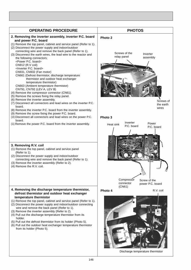
146
4. Removing the discharge temperature thermistor, defrost thermistor and outdoor heat exchanger temperature thermistor
(1) Remove the top panel, cabinet and service panel (Refer to 1).(2) Disconnect the power supply and indoor/outdoor connecting wire and remove the back panel (Refer to 1).(3) Remove the inverter assembly (Refer to 2).(4) Pull out the discharge temperature thermistor from its holder.(5) Pull out the defrost thermistor from its holder (Photo 5).(6) Pull out the outdoor heat exchanger temperature thermistor from its holder (Photo 5).
Photo 4
OPERATING PROCEDURE PHOTOS2. Removing the inverter assembly, inverter P.C. board and power P.C. board (1) Remove the top panel, cabinet and service panel (Refer to 1). (2) Disconnect the power supply and indoor/outdoor connecting wire and remove the back panel (Refer to 1).(3) Disconnect the earth wires, the lead wire to the reactor and the following connectors; <Power P.C. board> CN912 (R.V coil) <Inverter P.C. board> CN931, CN932 (Fan motor) CN661 (Defrost thermistor, discharge temperature thermistor and outdoor heat exchanger temperature thermistor) CN663 (Ambient temperature thermistor) CN791, CN792 (LEV A, LEV B)(4) Remove the compressor connector (CN61).(5) Remove the screws fixing the relay panel.(6) Remove the inverter assembly.(7) Disconnect all connectors and lead wires on the inverter P.C. board.(8) Remove the inverter P.C. board from the inverter assembly.(9) Remove the screw fixing the power P.C. board.(10) Disconnect all connectors and lead wires on the power P.C. board.(11) Remove the power P.C. board from the inverter assembly.
Photo 2
Photo 3
3. Removing R.V. coil (1) Remove the top panel, cabinet and service panel (Refer to 1).(2) Disconnect the power supply and indoor/outdoor connecting wire and remove the back panel (Refer to 1).(3) Remove the inverter assembly (Refer to 2).(4) Remove the R.V. coil.
Screws of therelay panel
Screws of the earth wires
Discharge temperature thermistor
R.V. coil
Screw of thepower P.C. board
Heat sink InverterP.C. board
PowerP.C. board
Inverterassembly
Compressor connector (CN61)

147
OPERATING PROCEDURE PHOTOS
Photo 5
Defrostthermistor
5. Removing outdoor fan motor(1) Remove the top panel, cabinet and service panel (Refer to 1).(2) Disconnect the power supply and indoor/outdoor connecting wire.(3) Disconnect the connectors for outdoor fan motor.(4) Remove the propeller nut. (5) Remove the propeller.(6) Remove the screws fixing the fan motor (Photo 6).(7) Remove the fan motor.
Photo 7
6. Removing the compressor and 4-way valve(1) Remove the top panel, cabinet and service panel (Refer to 1).(2) Disconnect the power supply and indoor/outdoor connecting wire and remove the back panel (Refer to 1).(3) Remove the inverter assembly (Refer to 2).(4) Recover gas from the refrigerant circuit.NOTE: Recover gas from the pipes until the pressure gauge shows 0 kg/cm2 (0 MPa).
(5) Detach the welded part of the suction and the discharge pipe connected with compressor.(6) Remove the nuts of compressor legs.(7) Remove the compressor.(8) Detach the welded part of pipes connected with 4-way valve (Photo 7).
Photo 6 Screws of the outdoor fan motor
Outdoor heatexchangertemperaturethermistor
Propeller
Welded parts of 4-way valve
Propeller nut

148
OPERATING PROCEDURE PHOTOS1. Removing the compressor(1) Remove the screws of the top panel, and remove the top panel.(2) Remove the screws of the service panel, and remove the service panel.(3) Recover gas from the refrigerant circuit.NOTE: Recover gas from the pipes until the pressure gauge shows 0 kg/cm2 (0 MPa).
(4) Remove the screws of the cabinet, and remove the cabinet.(5) Remove the screws of the back panel, and remove the back panel (Photo 3).(6) Disconnect the compressor lead wire from terminal of the compressor (U, V, W).(7) Disconnect the outdoor electronic control P.C. board connectors: CN661, CN662 (MXZ-3A54/4A71VA- , , ), CN663, CN791, CN792, CN793, CN794 (MXZ-4A71VA- , , , ), CN795, CN931, CN932 Disconnect the noise filter P.C. board connector: CN912(8) Remove the screws of the electrical parts, and remove the electrical parts (Photo 4).(9) Remove the propeller.(10) Remove the screws of the separator, and remove the separator (Photo 6).(11) Remove the sound proof felt (Photo 6).(12) Detach the welded parts of the compressor suction and dis-
charge pipes (Photo 5).(13) Remove the compressor nuts and remove the compressor.
Photo 2
14-2. MXZ-3A54VA - E1 , E2 , E3 , E4 MXZ-4A71VA - E1 , E2 , E3 , E4
Photo 1
Screws of the cabinet
Screws of the top panel
Screw of the cabinet
Screws of the cabinetScrews of service panel
Screws of the top panel
Screws of the cabinet
Screws of the cabinet
E1 E3E2
E1 E3E2 E4

149
OPERATING PROCEDURE PHOTOS
2. Removing the fan motor(1) Remove the top panel, the service panel, and the cabinet (Photo 1, 2).(2) Disconnect the connector CN931 and CN932 on the outdoor electronic control P.C. board.(3) Remove the propeller.(4) Remove the fan motor.
Photo 6
Screws of the outdoor fan motor
Propeller
Propeller nutSeparator
Sound proof felt
Photo 3
Screws ofthe electricalparts
Photo 4
R.V. coil
4 way valve
LEV coil E
Expansion valve E
Suction pipewelded part
Dischargepipe welded part
Photo 5
Compressor nuts
Screw of the rear guard
Screw of the back panel
Screws ofthe back panel
Screws ofthe back panel Screw of the
back panel
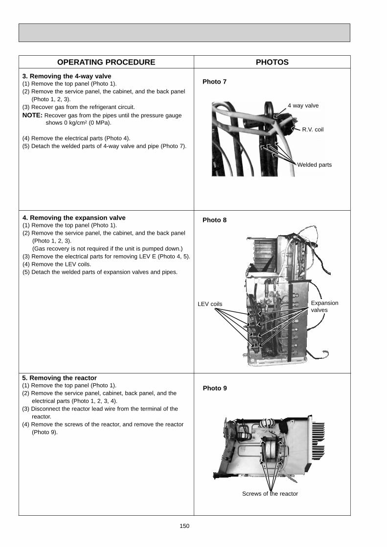
150
OPERATING PROCEDURE PHOTOS
5. Removing the reactor(1) Remove the top panel (Photo 1).(2) Remove the service panel, cabinet, back panel, and the electrical parts (Photo 1, 2, 3, 4).(3) Disconnect the reactor lead wire from the terminal of the reactor.(4) Remove the screws of the reactor, and remove the reactor (Photo 9).
Photo 9
Screws of the reactor
3. Removing the 4-way valve(1) Remove the top panel (Photo 1).(2) Remove the service panel, the cabinet, and the back panel (Photo 1, 2, 3).(3) Recover gas from the refrigerant circuit.NOTE: Recover gas from the pipes until the pressure gauge shows 0 kg/cm2 (0 MPa).
(4) Remove the electrical parts (Photo 4).(5) Detach the welded parts of 4-way valve and pipe (Photo 7).
4. Removing the expansion valve(1) Remove the top panel (Photo 1).(2) Remove the service panel, the cabinet, and the back panel (Photo 1, 2, 3). (Gas recovery is not required if the unit is pumped down.)(3) Remove the electrical parts for removing LEV E (Photo 4, 5).(4) Remove the LEV coils.(5) Detach the welded parts of expansion valves and pipes.
4 way valve
R.V. coil
Welded parts
LEV coils Expansion valves
Photo 7
Photo 8

151
OPERATING PROCEDURE PHOTOS1. Removing the compressor(1) Remove the screws of the top panel, and remove the top panel.(2) Remove the screws of the service panel, and remove the service panel.(3) Recover gas from the refrigerant circuit.NOTE: Recover gas from the pipes until the pressure gauge shows 0 kg/cm2 (0 MPa).
(4) Remove the screws of the cabinet, and remove the cabinet.(5) Remove the screws of the back panel, and remove the back panel (Photo 3).(6) Disconnect the compressor lead wire from terminal of the compressor (U, V, W).(7) Disconnect the outdoor electronic control P.C. board connectors: CN661, CN663, CN791, CN792, CN793, CN794 (MXZ-4A71VA- E5 , E6 , E7 ), CN795, CN931, CN932 Disconnect the noise filter P.C. board connector: CN912(8) Remove the screws of the electrical parts, and remove the electrical parts (Photo 4).(9) Remove the propeller.(10) Remove the screws of the separator, and remove the separator (Photo 6).(11) Remove the sound proof felt (Photo 6).(12) Detach the welded parts of the compressor suction and dis- charge pipes (Photo 5).(13) Remove the compressor nuts and remove the compressor.
Photo 2
14-3. MXZ-3A54VA - E5 , E6 , E7 MXZ-4A71VA - E5 , E6 , E7
Photo 1
Screws of the cabinet
Screws of the top panel
Screw of the cabinet
Screws of the cabinetScrews of service panel
Screws of the top panel
Screws of the cabinet
Screws of the cabinet
2. Removing the electronic control P.C. board(1) Remove the screws of the sub panel.(2) Remove the sub panel.(3) Disconnect all connectors and lead wires on the electronic control P.C. board.(4) Remove the electronic control P.C. board.
Screws of thesub panel

152
OPERATING PROCEDURE PHOTOS
3. Removing the fan motor(1) Remove the top panel, the service panel, and the cabinet (Photo 1, 2).(2) Disconnect the connector CN931 and CN932 on the outdoor electronic control P.C. board.(3) Remove the propeller.(4) Remove the fan motor.
Photo 6
Screws of the outdoor fan motor
PropellerPropeller nut
Separator
Sound proof felt
Photo 3
Photo 4
Photo 5
Screw of the rear guard
Screw of the back panel
Screw of theback panel
Screws ofthe back panel
Screws ofthe back panel
Screws ofthe electricalparts
R.V. coil
4 way valve
LEV coil E
Expansion valve E
Suction pipewelded part
Dischargepipe welded part
Compressor nuts
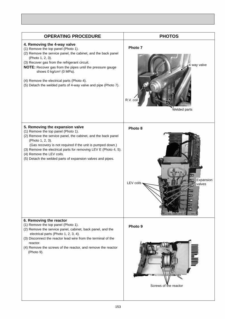
153
OPERATING PROCEDURE PHOTOS
6. Removing the reactor(1) Remove the top panel (Photo 1).(2) Remove the service panel, cabinet, back panel, and the electrical parts (Photo 1, 2, 3, 4).(3) Disconnect the reactor lead wire from the terminal of the reactor.(4) Remove the screws of the reactor, and remove the reactor (Photo 9).
Photo 9
4. Removing the 4-way valve(1) Remove the top panel (Photo 1).(2) Remove the service panel, the cabinet, and the back panel (Photo 1, 2, 3).(3) Recover gas from the refrigerant circuit.NOTE: Recover gas from the pipes until the pressure gauge shows 0 kg/cm2 (0 MPa).
(4) Remove the electrical parts (Photo 4).(5) Detach the welded parts of 4-way valve and pipe (Photo 7).
5. Removing the expansion valve(1) Remove the top panel (Photo 1).(2) Remove the service panel, the cabinet, and the back panel (Photo 1, 2, 3). (Gas recovery is not required if the unit is pumped down.)(3) Remove the electrical parts for removing LEV E (Photo 4, 5).(4) Remove the LEV coils.(5) Detach the welded parts of expansion valves and pipes.
4 way valve
R.V. coil
Expansion valves
Photo 7
Photo 8
LEV coils
Welded parts
Screws of the reactor

154
OPERATING PROCEDURE PHOTOS1. Removing the compressor(1) Remove the screws of the top panel, and remove the top
panel.(2) Remove the screws of the service panel, and remove the
service panel.(3) Recover gas from the refrigerant circuit.NOTE: Recover gas from the pipes until the pressure gauge shows 0 kg/cm2 (0 MPa).
(4) Remove the screws of the front panel, and remove the front panel.
(5) Disconnect the compressor lead wire from terminal of compressor (U, V, W). (6) Disconnect the outdoor electronic control P.C. board connectors: CN661, CN662 , CN663, CN681, CN791, CN792, CN793, CN794, CN795, CN931, CN932 Disconnect the noise filter P.C. board connector: CN912(7) Remove the screws of the electrical parts, and remove the electrical parts.(8) Remove the propeller.(9) Remove the screws of the separator, and remove the separator.(10) Remove the sound proof felt.(11) Detach the welded parts of the compressor suction and discharge pipes (Photo 3).(12) Remove the compressor nuts and remove the compressor.
Photo 1
Screws of service panel
Photo 2
Electroniccontrol P.C. board
14-4. MXZ-4A80VA - E1
Photo 3
Screws of the front panel
Screws of the top panel
Screws of the electrical parts
LEV coil E
Expansion valve E
Suction pipe welded part
Discharge pipe weld-ed part
Terminal
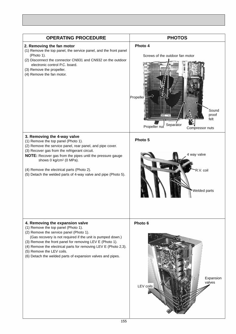
155
OPERATING PROCEDURE PHOTOS
3. Removing the 4-way valve(1) Remove the top panel (Photo 1).(2) Remove the service panel, rear panel, and pipe cover. (3) Recover gas from the refrigerant circuit.NOTE: Recover gas from the pipes until the pressure gauge shows 0 kg/cm2 (0 MPa).
(4) Remove the electrical parts (Photo 2).(5) Detach the welded parts of 4-way valve and pipe (Photo 5).
4. Removing the expansion valve(1) Remove the top panel (Photo 1).(2) Remove the service panel (Photo 1). (Gas recovery is not required if the unit is pumped down.)(3) Remove the front panel for removing LEV E (Photo 1).(4) Remove the electrical parts for removing LEV E (Photo 2,3).(5) Remove the LEV coils.(6) Detach the welded parts of expansion valves and pipes.
4 way valve
R.V. coil
Welded parts
LEV coils
Expansion valves
Photo 5
Photo 6
2. Removing the fan motor(1) Remove the top panel, the service panel, and the front panel (Photo 1).(2) Disconnect the connector CN931 and CN932 on the outdoor electronic control P.C. board.(3) Remove the propeller.(4) Remove the fan motor.
Photo 4
Screws of the outdoor fan motor
Propeller
Propeller nut SeparatorCompressor nuts
Sound proof felt
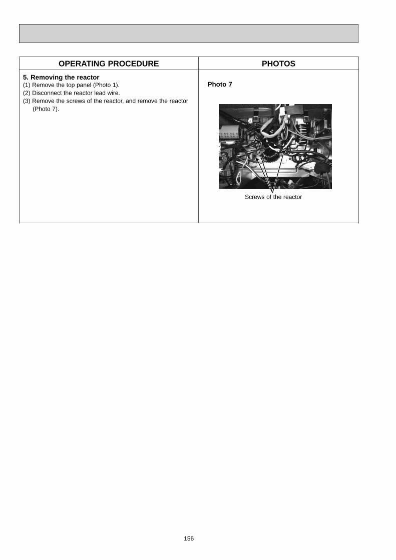
156
OPERATING PROCEDURE PHOTOS5. Removing the reactor(1) Remove the top panel (Photo 1).(2) Disconnect the reactor lead wire.(3) Remove the screws of the reactor, and remove the reactor
(Photo 7).
Photo 7
Screws of the reactor

157
OPERATING PROCEDURE PHOTOS1. Removing the compressor(1) Remove the screws of the top panel, and remove the top
panel.(2) Remove the screws of the service panel, and remove the
service panel.(3) Recover gas from the refrigerant circuit.NOTE: Recover gas from the pipes until the pressure gauge shows 0 kg/cm2 (0 MPa).
(4) Remove the screws of the front panel, and remove the front panel.
(5) Remove the screws of the rear panel, and remove the rear panel.
(6) Disconnect the compressor lead wire from terminal of compressor (U, V, W).(7) Disconnect the outdoor electronic control P.C. board connectors: CN661, CN663, CN681, CN791, CN792, CN793, CN794, CN795 (MXZ-5A100VA), CN796, CN931, CN932 Disconnect the noise filter P.C. board connector: CN912(8) Remove the screws of the electrical parts, and remove the electrical parts.(9) Remove the propeller.(10) Remove the screws of the separator, and remove the separator.(11) Remove the sound proof felt.(12) Detach the welded parts of the compressor suction and discharge pipes (Photo 4).(13) Remove the compressor nuts and remove the compressor.
Photo 1
Screws of the service panel
14-5. MXZ-4A80VA - E2 MXZ-5A100VA
Photo 4
Screws of the front panel
Screws of the top panel
Suction pipe welded part
Discharge pipe weld-ed part
Compressor nuts (3 places)
Screws of the side panel
Screws of the service panel
Screws of the top panel
Photo 2
Screws of the rear panel
Photo 3
Screws of the electrical parts

158
OPERATING PROCEDURE PHOTOS
3. Removing the 4-way valve(1) Remove the top panel (Photo 1).(2) Remove the service panel, rear panel, and pipe cover. (3) Recover gas from the refrigerant circuit.NOTE: Recover gas from the pipes until the pressure gauge shows 0 kg/cm2 (0 MPa).
(4) Remove the electrical parts (Photo 3).(5) Detach the welded parts of 4-way valve and pipe.
4. Removing the expansion valve(1) Remove the top panel (Photo 1,2).(2) Remove the service panel (Photo 1). (Gas recovery is not required if the unit is pumped down.)(3) Remove the font panel for removing LEV F (Photo 1).(4) Remove the electrical parts for removing LEV F (Photo 3).(5) Remove the LEV coils.(6) Detach the welded parts of expansion valves and pipes.
4 way valve
R.V. coil
Welded parts
Expansion valves
Photo 6
Photo 7
2. Removing the fan motor(1) Remove the top panel, the service panel, and the front panel (Photo 1).(2) Disconnect the connector CN931 and CN932 on the outdoor electronic control P.C. board.(3) Remove the propeller.(4) Remove the fan motor.
Photo 5
Propeller
Separator
Propeller nutSound proof felt
LEV coils
Expansion valve F
LEV coil F
Screws of the outdoor fan motor
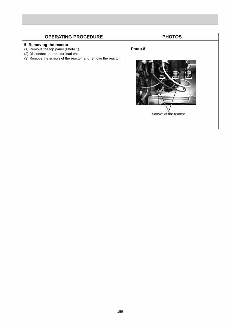
159
OPERATING PROCEDURE PHOTOS5. Removing the reactor(1) Remove the top panel (Photo 1).(2) Disconnect the reactor lead wire.(3) Remove the screws of the reactor, and remove the reactor.
Photo 8
Screws of the reactor
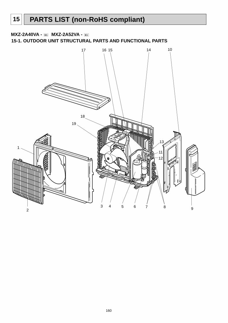
160
PARTS LIST (non-RoHS compliant)15
15-1. OUTDOOR UNIT STRUCTURAL PARTS AND FUNCTIONAL PARTS
11112
2
1517
13
10
9
MXZ-2A40VA - E1 MXZ-2A52VA - E1
3 4 5 6 7 8
16 14
18
19
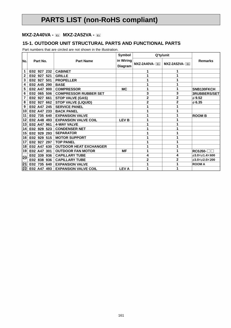
161
PARTS LIST (non-RoHS compliant)
E02 927 232E02 927 521E02 927 501E02 A45 290E02 A47 900E02 065 506E02 927 661E02 927 662E02 A47 245E02 A47 233E02 735 640E02 A48 493E02 A47 961E02 929 523 E02 929 293E02 929 515E02 927 297E02 A47 630E02 A47 301E02 339 936E02 838 936E02 735 640E02 A47 493
12345678910111213141516171819
20
2122
SNB130FKCH3RUBBERS/SET 9.52 6.35
ROOM B
RC0J50-3.0 1.4 6003.0 2.0 200
ROOM A
MC
LEV B
MF
LEV A
11111322111111111114211
11111322111111111114211
Symbolin WiringDiagram
Q'ty/unitRemarksPart No.No. Part Name
MXZ-2A40VA- E1 MXZ-2A52VA- E1
CABINETGRILLEPROPELLERBASECOMPRESSORCOMPRESSOR RUBBER SETSTOP VALVE (GAS)STOP VALVE (LIQUID)SERVICE PANELBACK PANELEXPANSION VALVEEXPANSION VALVE COIL4-WAY VALVECONDENSER NETSEPARATORMOTOR SUPPORTTOP PANELOUTDOOR HEAT EXCHANGEROUTDOOR FAN MOTORCAPILLARY TUBECAPILLARY TUBEEXPANSION VALVEEXPANSION VALVE COIL
15-1. OUTDOOR UNIT STRUCTURAL PARTS AND FUNCTIONAL PARTS
MXZ-2A40VA - E1 MXZ-2A52VA - E1
Part numbers that are circled are not shown in the illustration.
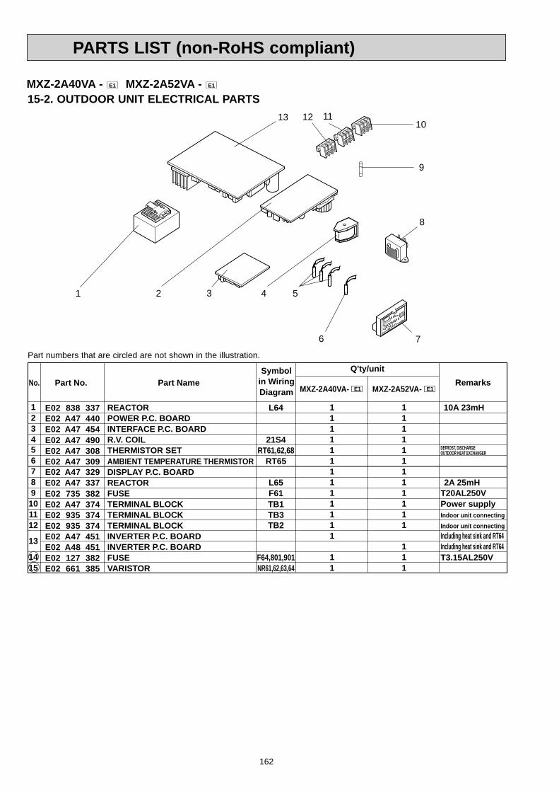
162
PARTS LIST (non-RoHS compliant)
15-2. OUTDOOR UNIT ELECTRICAL PARTS13 11
1 5
REACTORPOWER P.C. BOARDINTERFACE P.C. BOARDR.V. COILTHERMISTOR SETAMBIENT TEMPERATURE THERMISTORDISPLAY P.C. BOARDREACTORFUSETERMINAL BLOCKTERMINAL BLOCKTERMINAL BLOCKINVERTER P.C. BOARDINVERTER P.C. BOARDFUSEVARISTOR
E02 838 337E02 A47 440E02 A47 454E02 A47 490E02 A47 308E02 A47 309E02 A47 329E02 A47 337E02 735 382E02 A47 374E02 935 374E02 935 374E02 A47 451E02 A48 451E02 127 382E02 661 385
123456789101112
13
1415
Symbolin WiringDiagram
Q'ty/unit
T20AL250VPower supplyIndoor unit connectingIndoor unit connectingIncluding heat sink and RT64Including heat sink and RT64T3.15AL250V
RemarksPart No.No. Part Name
L64
21S4RT61,62,68
RT65
L65F61TB1TB3TB2
F64,801,901NR61,62,63,64
1111111111111
11
111111111111
111
MXZ-2A40VA- E1 MXZ-2A52VA- E1
DEFROST, DISCHARGEOUTDOOR HEAT EXCHANGER
10A 23mH
2A 25mH
MXZ-2A40VA - E1 MXZ-2A52VA - E1
2 3
9
1012
Part numbers that are circled are not shown in the illustration.
76
4
8

163
PARTS LIST (non-RoHS compliant)
Outdoor unit 42 drain hole
Soft vinyl chloride hose of 25 mm inside diameter
MXZ-2A40VA - E1 MXZ-2A52VA - E1
15-3. DRAIN SOCKET
Symbolin WiringDiagram
Q'ty/unit
MXZ-2A40VA- RemarksParts No. Parts NameE1 MXZ-2A52VA- E1
E02 838 7041 DRAIN SOCKET
No.
1 1
1
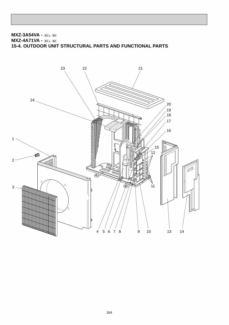
164
PARTS LIST (non-RoHS compliant)
MXZ-3A54VA - E1 , E2
MXZ-4A71VA - E1 , E2
15-4. OUTDOOR UNIT STRUCTURAL PARTS AND FUNCTIONAL PARTS
3
2
1
4 13
212223
24
11
12
5 6 7 8 9 10 14
15
16
17181920
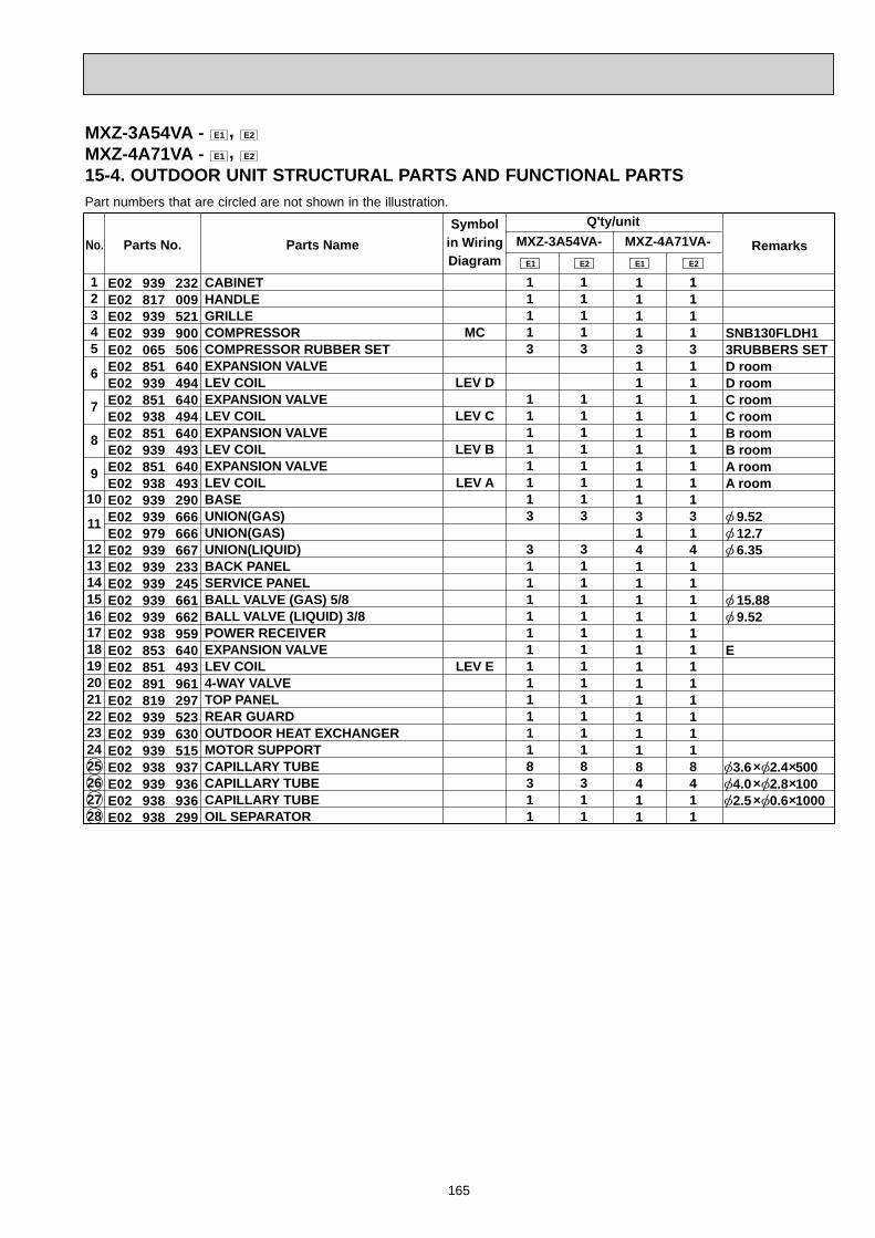
165
PARTS LIST (non-RoHS compliant)
Symbolin WiringDiagram
Q'ty/unitMXZ-3A54VA- RemarksParts No. Parts Name
E1
MXZ-4A71VA-E1E2 E2
E02 939 232E02 817 009E02 939 521E02 939 900E02 065 506E02 851 640E02 939 494E02 851 640E02 938 494E02 851 640E02 939 493E02 851 640E02 938 493E02 939 290E02 939 666E02 979 666E02 939 667E02 939 233E02 939 245E02 939 661E02 939 662E02 938 959E02 853 640E02 851 493E02 891 961E02 819 297E02 939 523E02 939 630E02 939 515E02 938 937E02 939 936E02 938 936E02 938 299
12345
6
7
8
9
10
11
1213141516171819202122232425262728
CABINETHANDLEGRILLECOMPRESSORCOMPRESSOR RUBBER SETEXPANSION VALVELEV COILEXPANSION VALVELEV COILEXPANSION VALVELEV COILEXPANSION VALVELEV COILBASEUNION(GAS)UNION(GAS)UNION(LIQUID)BACK PANELSERVICE PANELBALL VALVE (GAS) 5/8BALL VALVE (LIQUID) 3/8POWER RECEIVEREXPANSION VALVELEV COIL4-WAY VALVETOP PANELREAR GUARDOUTDOOR HEAT EXCHANGERMOTOR SUPPORTCAPILLARY TUBECAPILLARY TUBE CAPILLARY TUBEOIL SEPARATOR
No.
MC
LEV D
LEV C
LEV B
LEV A
LEV E
111131111111113141111111111118411
11113
11111113
31111111111118311
111131111111113141111111111118411
11113
11111113
31111111111118311
SNB130FLDH13RUBBERS SETD roomD roomC roomC roomB roomB roomA roomA room
9.52 12.7 6.35
15.88 9.52
E
3.6 2.4 500 4.0 2.8 100 2.5 0.6 1000
Part numbers that are circled are not shown in the illustration.
MXZ-3A54VA - E1 , E2
MXZ-4A71VA - E1 , E2
15-4. OUTDOOR UNIT STRUCTURAL PARTS AND FUNCTIONAL PARTS
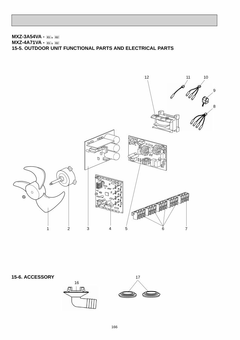
166
PARTS LIST (non-RoHS compliant)
10
9
8
1 2 43 5 7
12
6
MXZ-3A54VA - E1 , E2
MXZ-4A71VA - E1 , E2
15-5. OUTDOOR UNIT FUNCTIONAL PARTS AND ELECTRICAL PARTS
11
15-6. ACCESSORY16
17
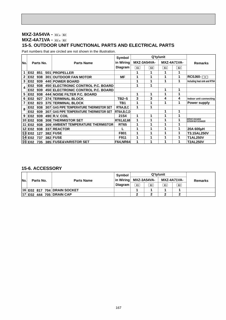
167
PARTS LIST (non-RoHS compliant)
Part numbers that are circled are not shown in the illustration.
Symbolin WiringDiagram
Q'ty/unitMXZ-3A54VA- RemarksParts No. Parts Name
E1
MXZ-4A71VA-E1E2 E2
E02 851 501E02 938 301E02 939 440E02 938 450E02 939 450E02 938 444E02 927 374E02 823 375E02 938 307E02 939 307E02 939 490E02 938 308E02 938 309E02 938 337E02 127 382E02 737 382E02 735 385
123
4
567
8
9101112131415
PROPELLEROUTDOOR FAN MOTORPOWER BOARDELECTRONIC CONTROL P.C. BOARDELECTRONIC CONTROL P.C. BOARDNOISE FILTER P.C. BOARDTERMINAL BLOCKTERMINAL BLOCKGAS PIPE TEMPERATURE THERMISTOR SETGAS PIPE TEMPERATURE THERMISTOR SETR.V. COILTHERMISTOR SETAMBIENT TEMPERATURE THERMISTORREACTORFUSEFUSEFUSE&VARISTOR SET
No.
MF
TB2~5TB1
RT6A,B,CRT6A,B,C,D
21S4RT61,62,68
RT65L
F801F911
F64,NR64
1111
1311
1111111
111
1141
11111111
1111
1311
1111111
111
1141
11111111
RC0J60-Including heat sink and RT64
Indoor unit connectingPower supply
20A 600μHT3.15AL250VT1AL250VT2AL250V
DEFROST, DISCHARGE OUTDOOR HEAT EXCHANGER
15-6. ACCESSORYSymbol
in WiringDiagram
Q'ty/unitMXZ-3A54VA- RemarksParts No. Parts Name
E1
MXZ-4A71VA-E2E2 E1
E02 817 704E02 444 705
1617
DRAIN SOCKETDRAIN CAP
No.
12
12
12
12
MXZ-3A54VA - E1 , E2
MXZ-4A71VA - E1 , E2
15-5. OUTDOOR UNIT FUNCTIONAL PARTS AND ELECTRICAL PARTS
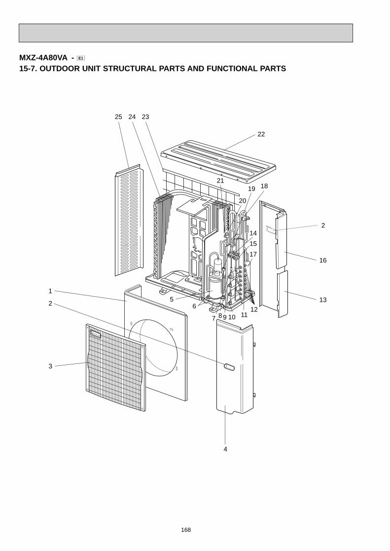
168
PARTS LIST (non-RoHS compliant)
MXZ-4A80VA - E1
15-7. OUTDOOR UNIT STRUCTURAL PARTS AND FUNCTIONAL PARTS
3
2
1
4
13
16
22
232425
56 12
117 8 9 10
171514
1819
20
21
2

169
PARTS LIST (non-RoHS compliant)
Symbolin WiringDiagram
Q'ty/unit
RemarksParts No. Parts Name MXZ-4A80VA- E1
M21 TK0 232M21 TK0 027M21 TK5 010M21 TK0 245T92 500 801T2W TK0 505R01 E39 401T2W TK0 654R01 E39 401T2W TK0 653R01 E39 401T2W TK0 652R01 E39 401T2W TK0 651M21 TK0 290M21 42E 644T2W TK0 247M21 TK5 667M21 TK0 667M21 TK0 248T2W TK0 959M21 G0H 642M21 NT1 646T2W WW8 401T2W TK0 651M21 TK0 297T2W E40 523M21 YH1 630M21 TK0 249M21 SJ4 937M21 TK0 936T2W E59 936T2W YH1 656
123456
7
8
9
10
11121314151617181920212223242526272829
FRONT PANELHANDLE ASSEMBLYGRILLESERVICE PANELCOMPRESSORCOMPRESSOR RUBBER SETEXPANSION VALVELEV COILEXPANSION VALVELEV COILEXPANSION VALVELEV COILEXPANSION VALVELEV COILBASE ASSEMBLYUNIONPIPE COVERBALL VALVE (LIQUID) 3/8BALL VALVE (GAS) 5/8REAR PANELPOWER RECEIVER4-WAY VALVEHIGH PRESSURE SWITCHEXPANSION VALVELEV COILTOP PANELREAR GUARDOUTDOOR HEAT EXCHANGERSIDE PANELCAPILLARY TUBECAPILLARY TUBECAPILLARY TUBEOIL SEPARATOR
No.
MC
LEV D
LEV C
LEV B
LEV A
HPS
LEV E
121113111111111111111111111112411
TNB220FMCH3RUBBERS SETD roomD roomC roomC roomB roomB roomA roomA room
12.7, 9.52, 6.35 SET
9.52 15.88
4.8 MPa (48.9 kg/cm2)E
4.0 2.4 400 4.0 2.8 90 2.5 0.6 1000
Part numbers that are circled are not shown in the illustration.
MXZ-4A80VA - E1
15-7. OUTDOOR UNIT STRUCTURAL PARTS AND FUNCTIONAL PARTS
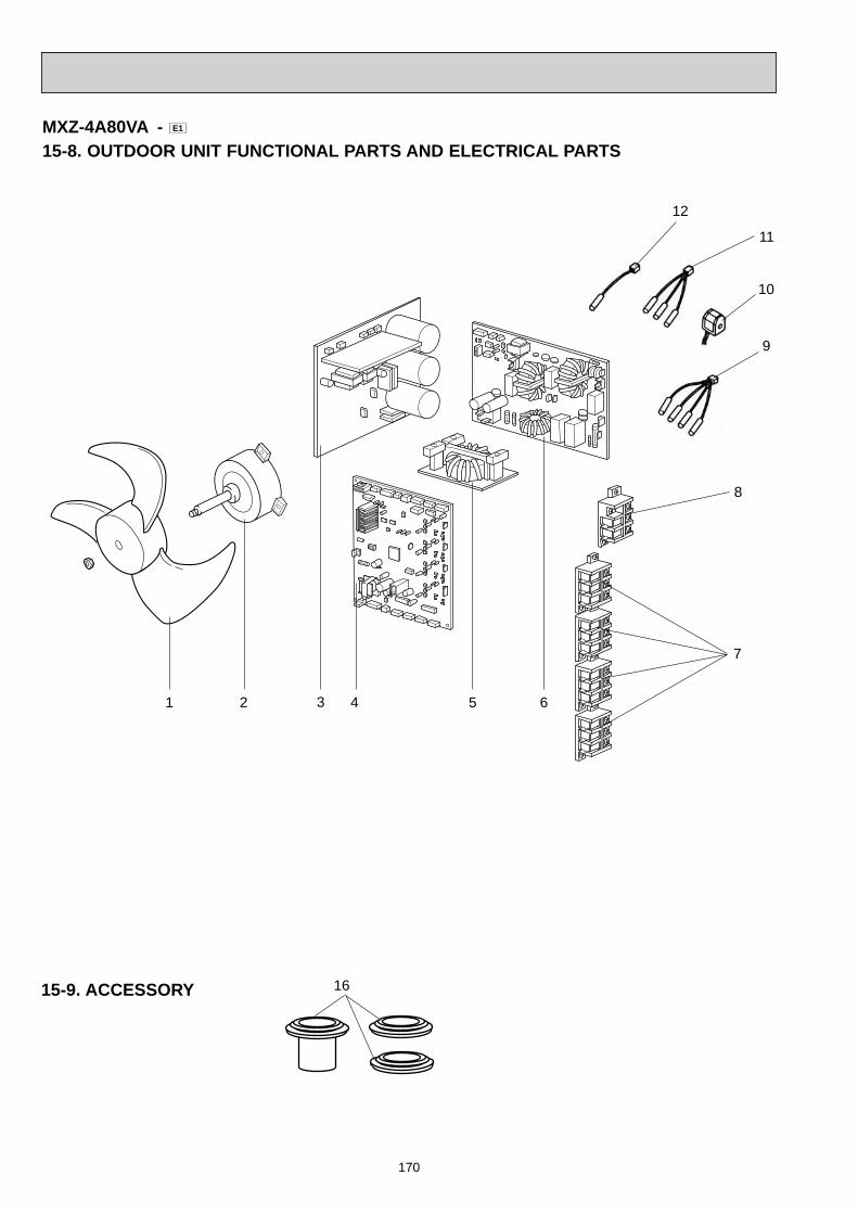
170
PARTS LIST (non-RoHS compliant)
1615-9. ACCESSORY
11
10
9
1 2 43 5 6
8
7
MXZ-4A80VA - E1
15-8. OUTDOOR UNIT FUNCTIONAL PARTS AND ELECTRICAL PARTS
12
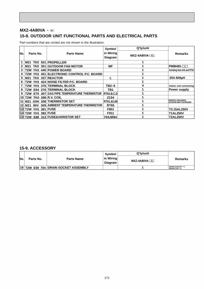
171
PARTS LIST (non-RoHS compliant)
Part numbers that are circled are not shown in the illustration.
Symbolin WiringDiagram
Q'ty/unit
RemarksParts No. Parts Name MXZ-4A80VA- E1
M21 TK0 501M21 TK0 301T2W YH1 440T2W YH1 451M21 TK0 337T2W YH1 424T2W YH1 376T2W E64 376T2W E70 307T2W TK0 398M21 G0H 308M21 90V 309T2W YH1 381T2W YH1 382T2W E88 313
123456789101112131415
PROPELLEROUTDOOR FAN MOTORPOWER BOARDELECTRONIC CONTROL P.C. BOARDREACTORNOISE FILTER P.C. BOARDTERMINAL BLOCKTERMINAL BLOCKGAS PIPE TEMPERATURE THERMISTORR.V. COILTHERMISTOR SETAMBIENT TEMPERATURE THERMISTORFUSEFUSEFUSE&VARISTOR SET
No.
MF
L
TB2~5TB1
RT6A,B,C,D21S4
RT61,62,68RT65F801F911
F64,NR64
111111411111111
PM8H60-
Indoor unit connecting
Including heat sink and RT64
Power supply
T1AL250VT2AL250V
T3.15AL250V
DEFROST, DISCHARGE, OUTDOOR HEAT EXCHANGER
20A 600μH
MXZ-4A80VA - E1
15-8. OUTDOOR UNIT FUNCTIONAL PARTS AND ELECTRICAL PARTS
15-9. ACCESSORYSymbol
in WiringDiagram
Q'ty/unit
RemarksParts No. Parts Name MXZ-4A80VA- E1
T2W E59 70416 DRAIN SOCKET ASSEMBLY
No.
1 DRAIN SOCKET 1DRAIN CAP 2
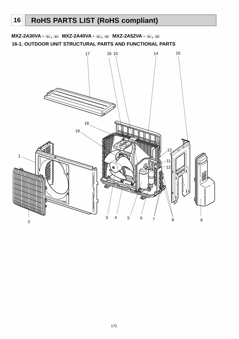
172
RoHS PARTS LIST (RoHS compliant)16
16-1. OUTDOOR UNIT STRUCTURAL PARTS AND FUNCTIONAL PARTS
11112
2
1517
13
10
9
MXZ-2A30VA - E1 , E2 MXZ-2A40VA - E1 , E2 MXZ-2A52VA - E1 , E2
3 4 5 6 7 8
16 14
18
19
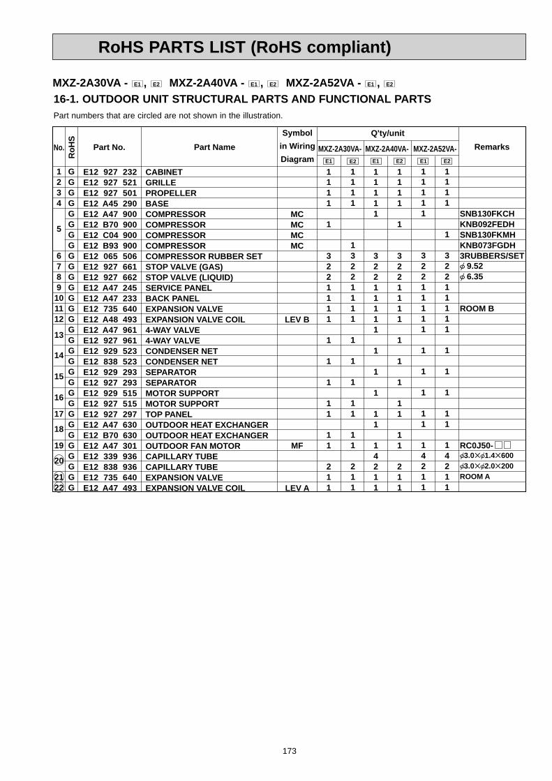
173
RoHS PARTS LIST (RoHS compliant)
E12 927 232E12 927 521E12 927 501E12 A45 290E12 A47 900E12 B70 900E12 C04 900E12 B93 900E12 065 506E12 927 661E12 927 662E12 A47 245E12 A47 233E12 735 640E12 A48 493E12 A47 961E12 927 961E12 929 523 E12 838 523E12 929 293E12 927 293E12 929 515E12 927 515E12 927 297E12 A47 630E12 B70 630E12 A47 301E12 339 936E12 838 936E12 735 640E12 A47 493
1234
5
6789101112
13
14
15
16
17
18
19
20
2122
SNB130FKCHKNB092FEDHSNB130FKMHKNB073FGDH3RUBBERS/SET 9.52 6.35
ROOM B
RC0J50- 3.0 1.4 600 3.0 2.0 200ROOM A
MCMCMCMC
LEV B
MF
LEV A
11111
32211111
1
1
1
11
14211
1111
1
3221111
1
1
1
11
11
211
11111
32211111
1
1
1
11
14211
1111
1
32211111
1
1
1
11
14211
Symbolin WiringDiagram
Q'ty/unitRemarksPart No.No.
GGGGGGGGGGGGGGGGGGGGGGGGGGGGGGG
RoH
S
Part Name MXZ-2A40VA- MXZ-2A52VA- E2E1E1 E2
1111
1
3221111
1
1
1
11
11
211
MXZ-2A30VA- E1
CABINETGRILLEPROPELLERBASECOMPRESSORCOMPRESSORCOMPRESSORCOMPRESSORCOMPRESSOR RUBBER SETSTOP VALVE (GAS)STOP VALVE (LIQUID)SERVICE PANELBACK PANELEXPANSION VALVEEXPANSION VALVE COIL4-WAY VALVE4-WAY VALVECONDENSER NETCONDENSER NETSEPARATORSEPARATORMOTOR SUPPORTMOTOR SUPPORTTOP PANELOUTDOOR HEAT EXCHANGEROUTDOOR HEAT EXCHANGEROUTDOOR FAN MOTORCAPILLARY TUBECAPILLARY TUBEEXPANSION VALVEEXPANSION VALVE COIL
E2
1111
13221111
1
1
1
11
11
211
Part numbers that are circled are not shown in the illustration.
16-1. OUTDOOR UNIT STRUCTURAL PARTS AND FUNCTIONAL PARTSMXZ-2A30VA - E1 , E2 MXZ-2A40VA - E1 , E2 MXZ-2A52VA - E1 , E2

174
RoHS PARTS LIST (RoHS compliant)
16-2. OUTDOOR UNIT ELECTRICAL PARTS13 11
1 5
REACTORPOWER P.C. BOARDINTERFACE P.C. BOARDR.V. COILTHERMISTOR SETAMBIENT TEMPERATURE THERMISTORDISPLAY P.C. BOARDREACTORFUSETERMINAL BLOCKTERMINAL BLOCKTERMINAL BLOCKINVERTER P.C. BOARDINVERTER P.C. BOARDINVERTER P.C. BOARDINVERTER P.C. BOARDINVERTER P.C. BOARDINVERTER P.C. BOARDFUSEVARISTOR
E12 838 337E12 A47 440E12 A47 454E12 A47 490E12 A47 308E12 A47 309E12 A47 329E12 A47 337E12 735 382E12 A47 374E12 935 374E12 935 374E12 A47 451E12 A48 451E12 B70 451E12 B71 451E12 C04 451E12 C58 451E12 127 382E12 661 385
123456789101112
13
1415
Symbolin WiringDiagram
Q'ty/unit
T20AL250VPower supplyIndoor unit connectingIndoor unit connectingIncluding heat sink and RT64Including heat sink and RT64Including heat sink and RT64Including heat sink and RT64Including heat sink and RT64Including heat sink and RT64T3.15AL250V
RemarksPart No.No.
GGGGGGGGGGGGGGGGGGGG
RoH
S
Part Name
L64
21S4RT61,62,68
RT65
L65F61TB1TB3TB2
F64,801,901NR61,62,63,64
1111111111111
11
111111111111
1
11
111111111111
1
11
111111111111
1
11
MXZ-2A40VA- MXZ-2A30VA- MXZ-2A52VA- E1E2 E2E1
111111111111
1
11
E1
DEFROST, DISCHARGEOUTDOOR HEAT EXCHANGER
10A 23mH
2A 25mH
E2
111111111111
111
MXZ-2A30VA - E1 , E2 MXZ-2A40VA - E1 , E2 MXZ-2A52VA - E1 , E2
2 3
9
1012
Part numbers that are circled are not shown in the illustration.
76
4
8
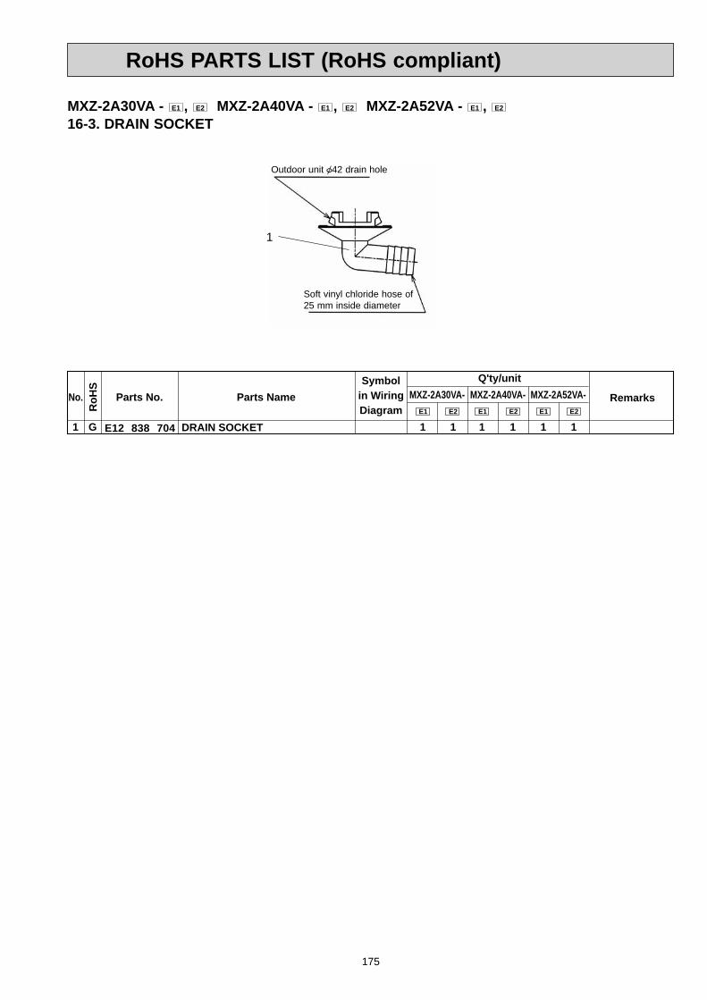
175
RoHS PARTS LIST (RoHS compliant)
Outdoor unit 42 drain hole
Soft vinyl chloride hose of 25 mm inside diameter
MXZ-2A30VA - E1 , E2 MXZ-2A40VA - E1 , E2 MXZ-2A52VA - E1 , E2
16-3. DRAIN SOCKET
Symbolin WiringDiagram
Q'ty/unit
RemarksParts No. Parts Name
E12 838 7041 DRAIN SOCKET
No.
G
RoH
S
1 1 1
MXZ-2A40VA-MXZ-2A30VA- MXZ-2A52VA-E1
1E2E1
1E2E1
1E2
1

176
RoHS PARTS LIST (RoHS compliant)
MXZ-3A54VA - E1 , E2 , E3 , E4
MXZ-4A71VA - E1 , E2 , E3 , E4
16-4. OUTDOOR UNIT STRUCTURAL PARTS AND FUNCTIONAL PARTS
3
2
1
4 13
212223
24
11
12
5 6 7 8 9 10 14
15
16
17181920
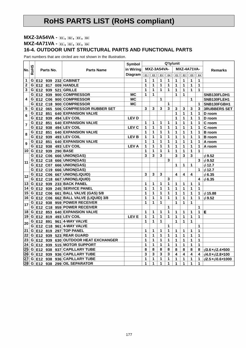
177
RoHS PARTS LIST (RoHS compliant)
Symbolin WiringDiagram
Q'ty/unitMXZ-3A54VA- RemarksParts No. Parts NameE1
MXZ-4A71VA-E1E2 E3 E4 E2 E3 E4
E12 939 232E12 817 009E12 939 521E12 939 900E12 C06 900E12 C18 900E12 065 506E12 851 640E12 939 494E12 851 640E12 938 494E12 851 640E12 939 493E12 851 640E12 938 493E12 939 290E12 C06 666E12 C18 666E12 C07 666E12 C19 666E12 C06 667E12 C18 667E12 939 233E12 939 245E12 C06 661E12 C06 662E12 938 959E12 C18 959E12 853 640E12 819 493E12 891 961E12 C18 961E12 819 297E12 939 523E12 939 630E12 939 515E12 938 937E12 939 936E12 938 936E12 938 299
123
4
5
6
7
8
9
10
11
12
13141516
17
1819
20
2122232425262728
CABINETHANDLEGRILLECOMPRESSORCOMPRESSORCOMPRESSORCOMPRESSOR RUBBER SETEXPANSION VALVELEV COILEXPANSION VALVELEV COILEXPANSION VALVELEV COILEXPANSION VALVELEV COILBASEUNION(GAS)UNION(GAS)UNION(GAS)UNION(GAS)UNION(LIQUID)UNION(LIQUID)BACK PANELSERVICE PANELBALL VALVE (GAS) 5/8BALL VALVE (LIQUID) 3/8POWER RECEIVERPOWER RECEIVEREXPANSION VALVELEV COIL4-WAY VALVE4-WAY VALVETOP PANELREAR GUARDOUTDOOR HEAT EXCHANGERMOTOR SUPPORTCAPILLARY TUBECAPILLARY TUBECAPILLARY TUBEOIL SEPARATOR
No.
GGGGGGGGGGGGGGGGGGGGGGGGGGGGGGGGGGGGGGGG
RoH
S
MCMCMC
LEV D
LEV C
LEV B
LEV A
LEV E
1111
31111111113
1
4
11111
111
11118411
1111
3
11111113
3
11111
111
11118311
1111
31111111113
1
4
11111
111
11118411
111
1
31111111113
1
4
11111
111
11118411
111
13111111111
3
1
41111
111
111118411
1111
3
11111113
3
11111
111
11118311
111
1
3
11111113
3
11111
111
11118311
111
13
1111111
3
31111
111
111118311
SNB130FLDH1SNB130FLEH1SNB130FGBH13RUBBERS SETD roomD roomC roomC roomB roomB roomA roomA room
9.52 9.52 12.7 12.7 6.35 6.35
15.88 9.52
E
3.6 2.4 500 4.0 2.8 100 2.5 0.6 1000
Part numbers that are circled are not shown in the illustration.
MXZ-3A54VA - E1 , E2 , E3 , E4
MXZ-4A71VA - E1 , E2 , E3 , E4
16-4. OUTDOOR UNIT STRUCTURAL PARTS AND FUNCTIONAL PARTS
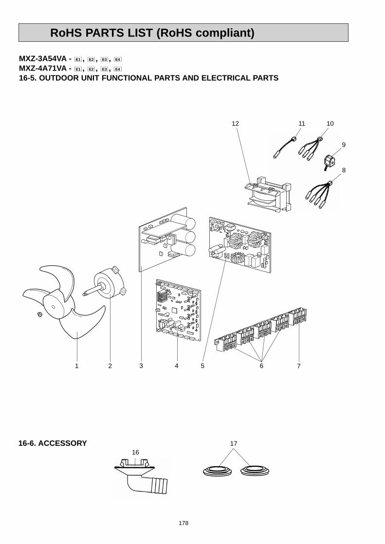
178
RoHS PARTS LIST (RoHS compliant)
10
9
8
1 2 43 5 7
12
6
MXZ-3A54VA - E1 , E2 , E3 , E4
MXZ-4A71VA - E1 , E2 , E3 , E4
16-5. OUTDOOR UNIT FUNCTIONAL PARTS AND ELECTRICAL PARTS
11
16-6. ACCESSORY16
17

179
RoHS PARTS LIST (RoHS compliant)
Part numbers that are circled are not shown in the illustration.
Symbolin WiringDiagram
Q'ty/unitMXZ-3A54VA- RemarksParts No. Parts Name MXZ-4A71VA-
E2 E3 E4E1 E2 E3 E4E1
E12 851 501E12 938 301E12 939 440E12 C07 440E12 938 450E12 939 450E12 C06 450E12 C07 450E12 C18 450E12 C19 450E12 938 444E12 927 374E12 823 375E12 938 307E12 939 307E12 939 490E12 C18 490E12 938 308E12 938 309E12 938 337E12 127 382E12 737 382E12 735 385
12
3
4
567
8
9
101112131415
PROPELLEROUTDOOR FAN MOTORPOWER BOARDPOWER BOARDELECTRONIC CONTROL P.C. BOARDELECTRONIC CONTROL P.C. BOARDELECTRONIC CONTROL P.C. BOARDELECTRONIC CONTROL P.C. BOARDELECTRONIC CONTROL P.C. BOARDELECTRONIC CONTROL P.C. BOARDNOISE FILTER P.C. BOARDTERMINAL BLOCKTERMINAL BLOCKGAS PIPE TEMPERATURE THERMISTOR SETGAS PIPE TEMPERATURE THERMISTOR SETR.V. COILR.V. COILTHERMISTOR SETAMBIENT TEMPERATURE THERMISTORREACTORFUSEFUSEFUSE&VARISTOR SET
No.
GGGGGGGGGGGGGGGGGGGGGGG
RoH
S
MF
TB2~5TB1
RT6A,B,CRT6A,B,C,D
21S421S4
RT61,62,68RT65
LF801F911
F64,NR64
111
1
1311
1
111111
111
1
141
11
111111
111
1
1311
1
111111
111
1
1311
1
111111
11
1
1
131
1111111
111
1
141
11
111111
111
1
141
11
111111
11
1
1141
1111111
RC0J60-Including heat sink and RT64Including heat sink and RT64
Indoor unit connectingPower supply
20A 600μHT3.15AL250VT1AL250VT2AL250V
DEFROST, DISCHARGE OUTDOOR HEAT EXCHANGER
16-6. ACCESSORYSymbol
in WiringDiagram
Q'ty/unitMXZ-3A54VA- RemarksParts No. Parts NameE1 E2 E3 E4 E1 E2 E3 E4
MXZ-4A71VA-
E12 817 704E12 444 705
1617
DRAIN SOCKETDRAIN CAP
No.
GG
RoH
S
12
12
12
12
12
12
12
12
MXZ-3A54VA - E1 , E2 , E3 , E4
MXZ-4A71VA - E1 , E2 , E3 , E4
16-5. OUTDOOR UNIT FUNCTIONAL PARTS AND ELECTRICAL PARTS

180
RoHS PARTS LIST (RoHS compliant)
MXZ-3A54VA - E5 , E6 , E7
MXZ-4A71VA - E5 , E6 , E7
16-7. OUTDOOR UNIT STRUCTURAL PARTS AND FUNCTIONAL PARTS
3
2
1
5 14
212223
12
13
6 7 8 9 10 11 15
16
17
18
19
20
4

181
RoHS PARTS LIST (RoHS compliant)
Symbolin WiringDiagram
Q'ty/unitMXZ-3A54VA- RemarksParts No. Parts Name MXZ-4A71VA-E5 E6 E6E5E7 E7
E12 D36 232E12 817 009E12 939 521E12 D36 246E12 C18 900E12 F10 900E12 C34 506E12 851 640E12 939 494E12 851 640E12 938 494E12 851 640E12 939 493E12 851 640E12 938 493E12 939 290E12 D36 666E12 D37 666E12 D36 667E12 939 233E12 D36 245E12 D36 662E12 D36 661E12 D36 299E12 C18 961E12 819 297E12 939 523E12 939 630E12 939 515E12 938 937E12 939 936E12 938 936E12 C18 959E12 853 640E12 819 493
1234
5
6
7
8
9
10
11
12
1314151617181920212223242526272829
CABINETHANDLEGRILLESUB PANELCOMPRESSORCOMPRESSORCOMPRESSOR RUBBER SETEXPANSION VALVELEV COILEXPANSION VALVELEV COILEXPANSION VALVELEV COILEXPANSION VALVELEV COILBASEUNION(GAS)UNION(GAS)UNION(LIQUID)BACK PANELSERVICE PANELSTOP VALVE (LIQUID) 3/8STOP VALVE (GAS) 5/8OIL SEPARATOR4-WAY VALVETOP PANELREAR GUARDOUTDOOR HEAT EXCHANGERMOTOR SUPPORTCAPILLARY TUBECAPILLARY TUBECAPILLARY TUBEPOWER RECEIVEREXPANSION VALVELEV COIL
No.
GGGGGGGGGGGGGGGGGGGGGGGGGGGGGGGGGGG
RoH
S
MCMC
LEV D
LEV C
LEV B
LEV A
LEV E
11111
31111111113141111111111841111
1111
131111111113141111111111841111
11111
31111111113141111111111841111
11111
3
11111113
31111111111831111
11111
3
11111113
31111111111831111
1111
13
11111113
31111111111831111
SNB130FGBH1SNB130FGBH1T3RUBBERS SETD roomD roomC roomC roomB roomB roomA roomA room
9.52 12.7 6.35
9.52 15.88
3.6 2.4 500 4.0 2.8 100 2.5 0.6 1000
E
Part numbers that are circled are not shown in the illustration.
MXZ-3A54VA - E5 , E6 , E7
MXZ-4A71VA - E5 , E6 , E7
16-7. OUTDOOR UNIT STRUCTURAL PARTS AND FUNCTIONAL PARTS

182
RoHS PARTS LIST (RoHS compliant)
9
8
1 2 43 5 7
11
6
MXZ-3A54VA - E5 , E6 , E7
MXZ-4A71VA - E5 , E6 , E7
16-8. OUTDOOR UNIT FUNCTIONAL PARTS AND ELECTRICAL PARTS
10
1516-9. ACCESSORY16

183
RoHS PARTS LIST (RoHS compliant)
Part numbers that are circled are not shown in the illustration.
Symbolin WiringDiagram
Q'ty/unitMXZ-3A54VA- RemarksParts No. Parts Name MXZ-4A71VA-E5 E6 E7 E5 E6 E7
E12 851 501E12 938 301E12 C07 440E12 D36 450E12 D87 450E12 F10 450E12 D37 450E12 D88 450E12 F11 450E12 D36 444E12 C92 375E12 D69 374E12 C18 490E12 938 308E12 938 309E12 938 337E12 784 382E12 250 382E12 977 385
123
4
567891011121314
PROPELLEROUTDOOR FAN MOTORPOWER BOARDELECTRONIC CONTROL P.C. BOARDELECTRONIC CONTROL P.C. BOARDELECTRONIC CONTROL P.C. BOARDELECTRONIC CONTROL P.C. BOARDELECTRONIC CONTROL P.C. BOARDELECTRONIC CONTROL P.C. BOARDNOISE FILTER P.C. BOARDTERMINAL BLOCKTERMINAL BLOCKR.V. COILTHERMISTOR SETAMBIENT TEMPERATURE THERMISTORREACTORFUSEFUSEFUSE&VARISTOR SET
No.
GGGGGGGGGGGGGGGGGGG
RoH
S
MF
TB2~5TB121S4
RT61,62,68RT65
LF801F65
F64,NR64
1111
1311111111
111
1
1311111111
111
1
1311111111
111
1
1411111111
111
1
1411111111
111
11411111111
RC0J60-Including heat sink and RT64
Indoor unit connectingPower supply
20A 600μHT3.15AL250VT6.3AL250VT2AL250V
DEFROST, DISCHARGE OUTDOOR HEAT EXCHANGER
16-9. ACCESSORYSymbol
in WiringDiagram
Q'ty/unitMXZ-3A54VA- RemarksParts No. Parts NameE5 E6 E5 E6
MXZ-4A71VA-E7 E7
E12 817 704E12 444 705
1516
DRAIN SOCKETDRAIN CAP
No.
GG
RoH
S
12
12
12
12
12
12
MXZ-3A54VA - E5 , E6 , E7
MXZ-4A71VA - E5 , E6 , E7
16-8. OUTDOOR UNIT FUNCTIONAL PARTS AND ELECTRICAL PARTS

184
RoHS PARTS LIST (RoHS compliant)
MXZ-4A80VA - E1
16-10. OUTDOOR UNIT STRUCTURAL PARTS AND FUNCTIONAL PARTS
3
2
1
4
13
16
22
232425
56 12
117 8 9 10
171514
1819
20
21
2
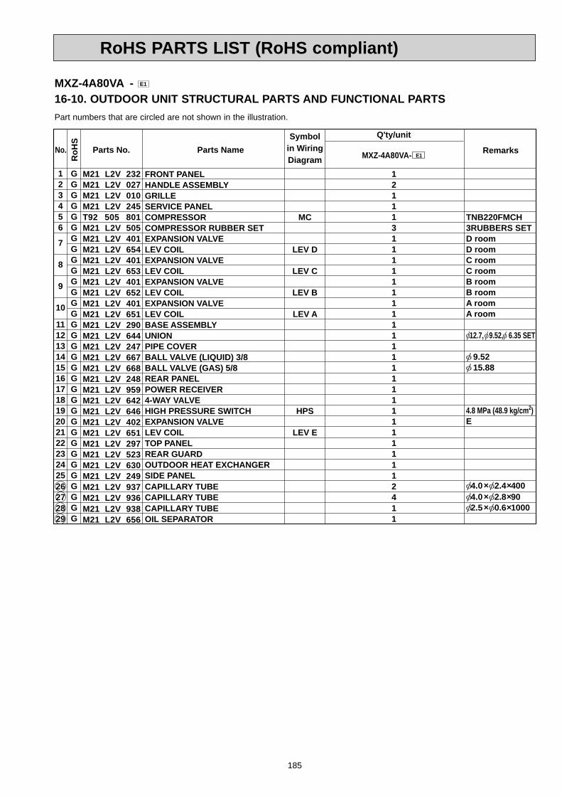
185
RoHS PARTS LIST (RoHS compliant)
Symbolin WiringDiagram
Q'ty/unit
RemarksParts Name MXZ-4A80VA- E1Parts No.
123456
7
8
9
10
11121314151617181920212223242526272829
No.
GGGGGGGGGGGGGGGGGGGGGGGGGGGGGGGGG
RoH
S
MC
LEV D
LEV C
LEV B
LEV A
HPS
LEV E
121113111111111111111111111112411
TNB220FMCH3RUBBERS SETD roomD roomC roomC roomB roomB roomA roomA room
12.7, 9.52, 6.35 SET
9.52 15.88
4.8 MPa (48.9 kg/cm2)E
4.0 2.4 400 4.0 2.8 90 2.5 0.6 1000
M21 L2V 232M21 L2V 027M21 L2V 010M21 L2V 245T92 505 801M21 L2V 505M21 L2V 401M21 L2V 654M21 L2V 401M21 L2V 653M21 L2V 401M21 L2V 652M21 L2V 401M21 L2V 651M21 L2V 290M21 L2V 644M21 L2V 247M21 L2V 667M21 L2V 668M21 L2V 248M21 L2V 959M21 L2V 642M21 L2V 646M21 L2V 402M21 L2V 651M21 L2V 297M21 L2V 523M21 L2V 630M21 L2V 249M21 L2V 937M21 L2V 936M21 L2V 938M21 L2V 656
FRONT PANELHANDLE ASSEMBLYGRILLESERVICE PANELCOMPRESSORCOMPRESSOR RUBBER SETEXPANSION VALVELEV COILEXPANSION VALVELEV COILEXPANSION VALVELEV COILEXPANSION VALVELEV COILBASE ASSEMBLYUNIONPIPE COVERBALL VALVE (LIQUID) 3/8BALL VALVE (GAS) 5/8REAR PANELPOWER RECEIVER4-WAY VALVEHIGH PRESSURE SWITCHEXPANSION VALVELEV COILTOP PANELREAR GUARDOUTDOOR HEAT EXCHANGERSIDE PANELCAPILLARY TUBECAPILLARY TUBE CAPILLARY TUBEOIL SEPARATOR
Part numbers that are circled are not shown in the illustration.
MXZ-4A80VA - E1
16-10. OUTDOOR UNIT STRUCTURAL PARTS AND FUNCTIONAL PARTS
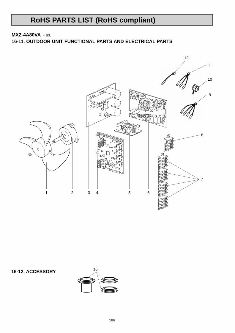
186
RoHS PARTS LIST (RoHS compliant)
1616-12. ACCESSORY
11
10
9
1 2 43 5 6
8
7
MXZ-4A80VA - E1
16-11. OUTDOOR UNIT FUNCTIONAL PARTS AND ELECTRICAL PARTS
12
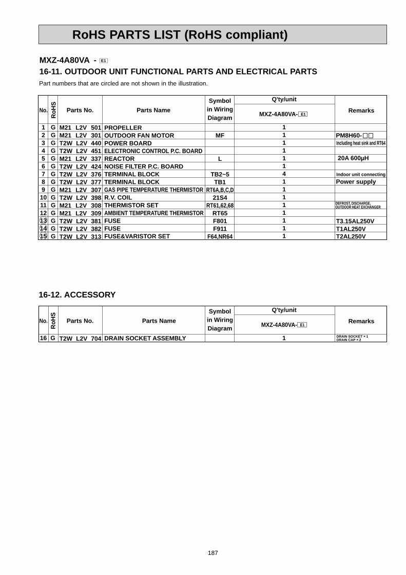
187
RoHS PARTS LIST (RoHS compliant)
Part numbers that are circled are not shown in the illustration.
Symbolin WiringDiagram
Q'ty/unit
RemarksParts No. Parts Name MXZ-4A80VA- E1
M21 L2V 501M21 L2V 301T2W L2V 440T2W L2V 451M21 L2V 337T2W L2V 424T2W L2V 376T2W L2V 377M21 L2V 307T2W L2V 398M21 L2V 308M21 L2V 309T2W L2V 381T2W L2V 382T2W L2V 313
123456789101112131415
PROPELLEROUTDOOR FAN MOTORPOWER BOARDELECTRONIC CONTROL P.C. BOARDREACTORNOISE FILTER P.C. BOARDTERMINAL BLOCKTERMINAL BLOCKGAS PIPE TEMPERATURE THERMISTORR.V. COILTHERMISTOR SETAMBIENT TEMPERATURE THERMISTORFUSEFUSEFUSE&VARISTOR SET
No.
GGGGGGGGGGGGGGG
RoH
S
MF
L
TB2~5TB1
RT6A,B,C,D21S4
RT61,62,68RT65F801F911
F64,NR64
111111411111111
PM8H60-
Indoor unit connecting
Including heat sink and RT64
Power supply
T1AL250VT2AL250V
T3.15AL250V
DEFROST, DISCHARGE, OUTDOOR HEAT EXCHANGER
20A 600μH
MXZ-4A80VA - E1
16-11. OUTDOOR UNIT FUNCTIONAL PARTS AND ELECTRICAL PARTS
16-12. ACCESSORY
Symbolin WiringDiagram
Q'ty/unit
RemarksParts No. Parts Name MXZ-4A80VA- E1
T2W L2V 70416 DRAIN SOCKET ASSEMBLY
No.
G
RoH
S
1 DRAIN SOCKET 1DRAIN CAP 2
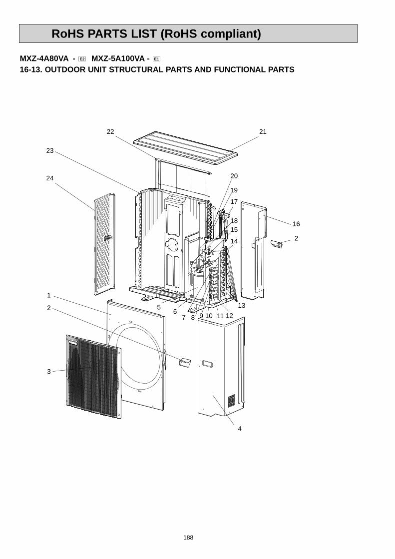
188
RoHS PARTS LIST (RoHS compliant)
MXZ-4A80VA - E2 MXZ-5A100VA - E1
16-13. OUTDOOR UNIT STRUCTURAL PARTS AND FUNCTIONAL PARTS
3
2
1
4
16
22
23
24
5 613
117 8 9 10
17
15
14
18
19
20
21
2
12

189
RoHS PARTS LIST (RoHS compliant)
Symbolin WiringDiagram
Q'ty/unit
RemarksParts Name MXZ-4A80VA- E2 MXZ-5A100VA- E1Parts No.
123456
7
8
9
10
11
12131415161718
19
202122
23
242526272829
No.
GGGGGGGGGGGGGGGGGGGGGGGGGGGGGGGGGGGG
RoH
S
MC
LEV E
LEV D
LEV C
LEV B
LEV A
HPS
LEV F
121113
1111111111111111
1111
112411
12111311111111111111111
1111
1112511
TNB220FMCH3RUBBERS SETE roomE roomD roomD roomC roomC roomB roomB roomA roomA room
12.7, 9.52, 6.35 SET 9.52 15.88
4.8 MPa (48.9 kg/cm2)FF
3.0 2.0 300 4.0 2.8 100 2.5 0.6 1000
M21 0A2 232M21 0A2 027M21 L2V 010M21 0A2 245T92 505 801M21 L2V 505M21 L2V 401M21 0A2 651M21 L2V 401M21 L2V 654M21 L2V 401M21 L2V 653M21 L2V 401M21 L2V 652M21 L2V 401M21 L2V 651M21 0A2 290M21 0A2 644M21 0A2 668M21 0A2 667M21 0A2 248M21 L2V 642M21 L2V 646M21 L2V 402M21 0A2 402M21 0A2 652M21 L2V 297M21 0A2 523M21 0A3 630T2W 0A2 630M21 L2V 249M21 L2V 959M21 0A2 937M21 0A2 936M21 L2V 938M21 L2V 656
FRONT PANELHANDLE ASSEMBLYGRILLESERVICE PANELCOMPRESSORCOMPRESSOR RUBBER SETEXPANSION VALVELEV COILEXPANSION VALVELEV COILEXPANSION VALVELEV COILEXPANSION VALVELEV COILEXPANSION VALVELEV COILBASE ASSEMBLYUNIONSTOP VALVE (LIQUID) 3/8STOP VALVE (GAS) 5/8REAR PANEL4-WAY VALVEHIGH PRESSURE SWITCHEXPANSION VALVEEXPANSION VALVELEV COILTOP PANELREAR GUARDOUTDOOR HEAT EXCHANGEROUTDOOR HEAT EXCHANGERSIDE PANELPOWER RECEIVERCAPILLARY TUBECAPILLARY TUBE CAPILLARY TUBEOIL SEPARATOR
Part numbers that are circled are not shown in the illustration.
MXZ-4A80VA - E2 MXZ-5A100VA - E1
16-13. OUTDOOR UNIT STRUCTURAL PARTS AND FUNCTIONAL PARTS

190
RoHS PARTS LIST (RoHS compliant)
1516-15. ACCESSORY
10
9
1 2 43 5 6
8
7
MXZ-4A80VA - E2 MXZ-5A100VA - E1
16-14. OUTDOOR UNIT FUNCTIONAL PARTS AND ELECTRICAL PARTS
11

191
RoHS PARTS LIST (RoHS compliant)
Part numbers that are circled are not shown in the illustration.
Symbolin WiringDiagram
Q'ty/unit
RemarksParts No. Parts Name MXZ-4A80VA- E2 MXZ-5A100VA- E1
M21 L2V 501M21 L2V 301M21 0A1 440T2W 0A3 451T2W 0A2 451M21 L2V 337M21 0A0 424T2W 0A2 376T2W L2V 377T2W L2V 398M21 L2V 308M21 0A2 309T2W L2V 381M21 0A2 313M21 T0A 313
123
4
567891011121314
PROPELLEROUTDOOR FAN MOTORPOWER BOARDELECTRONIC CONTROL P.C. BOARDELECTRONIC CONTROL P.C. BOARDREACTORNOISE FILTER P.C. BOARDTERMINAL BLOCKTERMINAL BLOCKR.V. COILTHERMISTOR SETAMBIENT TEMPERATURE THERMISTORFUSEFUSE&VARISTOR SETFUSE
No.
GGGGGGGGGGGGGGG
RoH
S
MF
L
TB2~6TB121S4
RT61,62,68RT65
F801,931F64,NR64
F65
1111
1141111111
111
11151111111
PM8H60-
Indoor unit connecting
Including heat sink and RT64
Power supply
T2AL250VT6.3AL250V
T3.15AL250V
DEFROST, DISCHARGE, OUTDOOR HEAT EXCHANGER
20A 600μH
MXZ-4A80VA - E2 MXZ-5A100VA - E1
16-14. OUTDOOR UNIT FUNCTIONAL PARTS AND ELECTRICAL PARTS
16-15. ACCESSORY
Symbolin WiringDiagram
Q'ty/unit
RemarksParts No. Parts Name MXZ-4A80VA- E2 MXZ-5A100VA- E1
T2W L2V 70415 DRAIN SOCKET ASSEMBLY
No.
G
RoH
S
1 1 DRAIN SOCKET 1DRAIN CAP 2

OPTIONAL PARTS17
17-1. DIFFERENT-DIAMETER PIPEUnit: mm (inch)
BA
C
17-2. OUTLET GUIDE Changes air discharge direction.
MAC-889SG
538524 7
48
15.7 13
.752
.5°
Punched hole 4 - 6
450.
8
10 x
48
(=48
0)
42.6
71.6
Z-Z
7
7932
710
3.1
537.
2
Z
Z
610.4534
534
386
416
51.8
150
109.4
29.2
760.
829
.2
6.4
6.4
832
386
Punched hole
Punched hole
5 - 6
5 - 6
MAC-855SG
Model name Model codeApplied unit
MAC-889SG 506-889
MXZ-2A30MXZ-2A40MXZ-2A52MXZ-3A54MXZ-4A71
MAC-855SG 51H-855MXZ-4A80MXZ-5A100
For different-diameterpipes
MXZ-3A54MXZ-4A71MXZ-4A80MXZ-5A100
Model name Connected pipes diameter
LengthA
LengthB
LengthC
MAC-A454JP 9.52 (3/8)
12.7 (1/2)
9.52 — 12.7 (3/8) (1/2) 69
PAC-SG76RJ-E 101.5 9.52 — 15.88(3/8) (5/8)
15.88(5/8)
9.52 (3/8)
PAC-493PI 60.5 6.35 — 9.52 (1/4) (3/8)
9.52 (3/8)
6.35 (1/4)
MAC-A456JP 66.5 12.7 — 15.88(1/2) (5/8)
15.88(5/8)
12.7 (1/2)
MAC-A455JP 65 12.7 — 9.52 (1/2) (3/8)
9.52 (3/8)
12.7 (1/2)
Copyright 2005 MITSUBISHI ELECTRIC ENGINEERING CO.,LTDDistributed in Dec. 2008. No.OB377 REVISED EDITION-H 6Distributed in Sep. 2008. No.OB377 REVISED EDITION-G 6Distributed in Dec. 2007. No.OB377 REVISED EDITION-F 8Distributed in Aug. 2007. No.OB377 REVISED EDITION-E 8Distributed in May 2007. No.OB377 REVISED EDITION-D 8Distributed in Feb. 2007. No.OB377 REVISED EDITION-C 8Distributed in Oct. 2006. No.OB377 REVISED EDITION-B 8Distributed in Dec. 2005. No.OB377 REVISED EDITION-A 8Distributed in Feb. 2005. No.OB377 8Made in Japan
New publication, effective Dec. 2008Specifications subject to change without notice.
HEAD OFFICE: TOKYO BLDG., 2-7-3, MARUNOUCHI, CHIYODA-KU, TOKYO 100-8310, JAPAN