Outdoor Unit: 24-TON PURY-P288YSKMU-A (-BS)...
4
Specifications are subject to change without notice. © 2016 Mitsubishi Electric US, Inc. Job Name: System Reference: Date: Specifications System Module 1 Module 2 Unit Type PURY-P288YSKMU-A (-BS) PURY-P144YKMU-A (-BS) PURY-P144YKMU-A (-BS) Nominal Cooling Capacity (460V) Btu/h 288,000 144,000 144,000 Nominal Heating Capacity (460V) Btu/h 320,000 160,000 160,000 Operating Temperature Range *1 Cooling (Outdoor) *2 Refer to Module Data 23~115° F (-5~46° C) DB Heating (Outdoor) -13~60° F (-25~15.5° C) WB External Dimensions (H x W x D) In. (mm) Refer to Module Data 64-31/32 x 68-29/32 x 29-5/32 (1,650 x 1,750 x 740) 64-31/32 x 68-29/32 x 29-5/32 (1,650 x 1,750 x 740) Net Weight Lbs. (kg) 1,486 (674) 743 (337) 743 (337) External Finish Refer to Module Data Pre-coated galvanized steel sheet Electrical Power Requirements Voltage, Phase, Hertz Refer to Module Data** 460V, 3-Phase, 60Hz Minimum Circuit Ampacity (MCA) A Refer to Module Data** 24 24 Maximum Fuse Size A Refer to Module Data** 30 30 Piping Diameter From Twinning Kit to Indoor Units (Brazed) (In. / mm) Liquid (High Pressure) 1-1/8 (28.58) Brazed Refer to System Data Gas (Low Pressure) 1-3/8 (34.93) Brazed Max. Total Refrigerant Line Length Ft. 3,117 Refer to System Data Max. Refrigerant Line Length (Between ODU & IDU) Ft. 541 Max. Control Wiring Length Ft. 1,650 Indoor Unit Total Capacity 50~150% of ODUs Refer to System Data Model / Quantity P06~P96/2~50 (Max. No. Connectable Branches: 48) Refer to System Data Sound Pressure Level dB(A) 64 Refer to System Data Fan Type x Quantity Refer to Module Data Propeller fan x 1 Propeller fan x 1 Airflow Rate CFM 11,300 11,300 External Static Pressure In. WG Refer to Module Data Selectable; 0, 0.12 or 0.24”WG; factory set to 0”W.G. Compressor Operating Range 7% to 100% Refer to System Data Compressor Type x Quantity Refer to Module Data Inverter-driven Scroll Hermetic x 1 Inverter-driven Scroll Hermetic x 1 Refrigerant Refer to Module Data R410A; 26 lbs. + 1 oz. (11.8 kg) R410A; 26 lbs. + 1 oz. (11.8 kg) Protection Devices High Pressure Refer to Module Data High pressure sensor, High pressure switch at 4.15 MPa (601 psi) High pressure sensor, High pressure switch at 4.15 MPa (601 psi) Inverter Circuit (Comp. / Fan) Over-current protection Over-current protection Fan Motor Thermal switch Thermal switch AHRI Ratings (Ducted/Non-Ducted) EER 11.2 / 11.3 Refer to System Data IEER 17.6 / 18.6 COP 3.41 / 3.20 SCHE 18.20 / 19.03 Blue Fin Anti-corrosion Protection: Cellulose- and polyurethane-resin coating treatment applied to condenser coil that protects it from air contaminants Standard: ≥1μm thick; Salt Spray Test Method - no unusual rust development to 480 hours. Seacoast (BS): ≥1μm thick; Salt Spray Test Method - no unusual rust development to 960 hours. UNIT OPTION □ Standard Model……..…...……......………….PURY-P288YSKMU-A □ Seacoast (BS) Model……........………...PURY-P288YSKMU-A-BS Outdoor Unit: 24-TON PURY-P288YSKMU-A (-BS) (Consists of Two PURY-P144YKMU-A (-BS) and One CMY-R100XLCBK Twinning Kit) OUTDOOR VRF HEAT PUMP WITH HEAT RECOVERY SYSTEM FEATURES • INVERTER-driven compressor • Air-source, simultaneous cooling and heating • Long line lengths - for details see Engineering Manual • Connects to CITY MULTI ® indoor units • Controlled via CITY MULTI ® Controls Network OPTIONAL PARTS □ Twinning Kit (required)............................................…CMY-R100XLCBK □ Joint Kit.............................…for details see Pipe Accesories Submittal □ BC Controller (required)…..............for details see BC Controller Submittals □ Low Ambient Kit ...............…..for details see Low Ambient Kit Submittal □ Snow/Hail Guards Kit......…for details see Snow/Hail Guards Kit Submittal NOTES: *1. When applying product below -4° F, consult your design engineer for cold climate application best practices, including the use of a backup source for heating. *2. For details on extended cooling operation range down to -10° F DB, see Low Ambient Kit Submittal. ** Each individual module requires a separate electrical connection. Refer to electrical data for each individual module.
Transcript of Outdoor Unit: 24-TON PURY-P288YSKMU-A (-BS)...

Specifications are subject to change without notice. © 2016 Mitsubishi Electric US, Inc.
Job Name:
System Reference: Date:
Specifications System Module 1 Module 2Unit Type PURY-P288YSKMU-A (-BS) PURY-P144YKMU-A (-BS) PURY-P144YKMU-A (-BS)
Nominal Cooling Capacity (460V) Btu/h 288,000 144,000 144,000Nominal Heating Capacity (460V) Btu/h 320,000 160,000 160,000
Operating Temperature Range *1 Cooling (Outdoor) *2 Refer to Module Data 23~115° F (-5~46° C) DB Heating (Outdoor) -13~60° F (-25~15.5° C) WB
External Dimensions (H x W x D) In. (mm) Refer to Module Data 64-31/32 x 68-29/32 x 29-5/32(1,650 x 1,750 x 740)
64-31/32 x 68-29/32 x 29-5/32 (1,650 x 1,750 x 740)
Net Weight Lbs. (kg) 1,486 (674) 743 (337) 743 (337)External Finish Refer to Module Data Pre-coated galvanized steel sheetElectrical Power Requirements Voltage, Phase, Hertz Refer to Module Data** 460V, 3-Phase, 60HzMinimum Circuit Ampacity (MCA) A Refer to Module Data** 24 24Maximum Fuse Size A Refer to Module Data** 30 30Piping DiameterFrom Twinning Kit to Indoor Units (Brazed) (In. / mm)
Liquid (High Pressure) 1-1/8 (28.58) Brazed Refer to System DataGas (Low Pressure) 1-3/8 (34.93) BrazedMax. Total Refrigerant Line Length Ft. 3,117
Refer to System DataMax. Refrigerant Line Length (Between ODU & IDU) Ft. 541
Max. Control Wiring Length Ft. 1,650
Indoor Unit
Total Capacity 50~150% of ODUs Refer to System Data
Model / QuantityP06~P96/2~50
(Max. No. Connectable Branches: 48)
Refer to System Data
Sound Pressure Level dB(A) 64 Refer to System DataFanType x Quantity
Refer to Module DataPropeller fan x 1 Propeller fan x 1
Airflow Rate CFM 11,300 11,300External Static Pressure In. WG Refer to Module Data Selectable; 0, 0.12 or 0.24”WG; factory set to 0”W.G.Compressor Operating Range 7% to 100% Refer to System Data
Compressor Type x Quantity Refer to Module Data Inverter-driven Scroll Hermetic x 1
Inverter-driven Scroll Hermetic x 1
Refrigerant Refer to Module Data R410A; 26 lbs. + 1 oz. (11.8 kg)
R410A; 26 lbs. + 1 oz. (11.8 kg)
Protection Devices
High Pressure
Refer to Module Data
High pressure sensor, High pressure switch at 4.15 MPa (601
psi)
High pressure sensor, High pressure switch at 4.15 MPa (601
psi)Inverter Circuit (Comp. / Fan) Over-current protection Over-current protection
Fan Motor Thermal switch Thermal switch
AHRI Ratings(Ducted/Non-Ducted)
EER 11.2 / 11.3
Refer to System DataIEER 17.6 / 18.6COP 3.41 / 3.20SCHE 18.20 / 19.03
Blue Fin Anti-corrosion Protection: Cellulose- and polyurethane-resin coating treatment applied to condenser coil that protects it from air contaminantsStandard: ≥1μm thick; Salt Spray Test Method - no unusual rust development to 480 hours.Seacoast (BS): ≥1μm thick; Salt Spray Test Method - no unusual rust development to 960 hours.
UNIT OPTION □ Standard Model……..…...……......………….PURY-P288YSKMU-A □ Seacoast (BS) Model……........………...PURY-P288YSKMU-A-BS
Outdoor Unit: 24-TON PURY-P288YSKMU-A (-BS)(Consists of Two PURY-P144YKMU-A (-BS) and One CMY-R100XLCBK Twinning Kit)
OUTDOOR VRF HEAT PUMP WITH HEAT RECOVERY SYSTEM FEATURES• INVERTER-driven compressor• Air-source, simultaneous cooling and heating• Long line lengths - for details see Engineering Manual• Connects to CITY MULTI® indoor units• Controlled via CITY MULTI® Controls Network
OPTIONAL PARTS □ Twinning Kit (required)............................................…CMY-R100XLCBK □ Joint Kit.............................…for details see Pipe Accesories Submittal □ BC Controller (required)…..............for details see BC Controller Submittals □ Low Ambient Kit ...............…..for details see Low Ambient Kit Submittal □ Snow/Hail Guards Kit......…for details see Snow/Hail Guards Kit Submittal
NOTES:*1. When applying product below -4° F, consult your design engineer for cold climate application best practices, including the use of a backup source for heating.*2. For details on extended cooling operation range down to -10° F DB, see Low Ambient Kit Submittal.
** Each individual module requires a separate electrical connection. Refer to electrical data for each individual module.

Specifications are subject to change without notice. © 2016 Mitsubishi Electric US, Inc.
Outdoor Unit: PURY-P288YSKMU-A (-BS) – DIMENSIONS
Intak
eair
Intak
eair
Intak
eair
Disc
harg
e air
Outdo
or un
it 1Ou
tdoor
unit 2
Fron
t view
Left
view
Note
1.C
onne
ct th
e pip
es a
s sho
wn in
the
figur
e ab
ove.
Ref
er to
the
table
abo
ve fo
r the
pipe
size
.
2.T w
inning
pipe
(High
pre
ssur
e) sh
ould
not b
e tilt
ed m
ore
than
15
degr
ees f
rom
the
horiz
onta
l plan
e.
Be su
re to
see
the
Insta
llatio
n M
anua
l for d
etail
s of T
winn
ing p
ipe in
stalla
tion.
3.
The
pipe
secti
on b
efor
e th
e Twi
nning
pipe
(sec
tion
"a" i
n th
e fig
ure)
mus
t hav
e at
leas
t 500
mm
(19-
11/1
6) o
f stra
ight s
ectio
n
(*i
nclud
ing th
e str
aight
pipe
that
is su
pplie
d wi
th th
e Twi
nning
pipe
).
4.On
ly us
e th
e Twi
nning
pipe
by M
itsub
ishi (
optio
nal p
arts)
.
5.Co
nnec
t the
out
door
unit
1 w
ith th
e Twi
nning
pipe
(Low
pre
ssur
e) (s
ectio
n "d
" in
the
figur
e).
Outd
oor u
nit 2
Outd
oor T
winn
ing K
it(op
tiona
l par
ts)Hi
gh pr
essu
reba
BC co
ntro
ller~
Twinn
ing p
ipe
Pack
age
unit n
ame
Com
pone
nt u
nit n
ame
Outd
oor u
nit 1
Twinn
ing p
ipe co
nnec
tion
size Lo
w pr
essu
reø3
4.93
(1-3
/8)
CMY-
R100
XLCB
Kø2
8.58
(1-1
/8)
P120
ø28.
58(1
-1/8
)
P144
Twinn
ing K
it
~Out
door
unit
P120
High
pre
ssur
ef
de
cø1
9.05
(3/4
)ø2
2.2(
7/8)
Com
pone
nt
unit m
odel
Unit m
odel
Low
pres
sure
c d(N
ote 5)
-ø1
9.05
(3/4
)
P240
P120
eø1
9.05
(3/4
)ø2
8.58
(1-1
/8)
f-
(Note
5)P264
P288
P144
c dø2
2.2(
7/8)
-(N
ote 5)
ø28.
58(1
-1/8
)e f
P144
ø22.
2(7/
8)
PURY
-P240
YSKM
UPU
RY-P2
64YS
KMU
PURY
-P288
YSKM
UPU
RY-P1
20YK
MUPU
RY-P1
44YK
MUPU
RY-P1
44YK
MUPU
RY-P1
20YK
MUPU
RY-P1
20YK
MUPU
RY-P1
44YK
MU
bTo
BC
contr
oller
fTw
inning
pipe
(High
pres
sure
)<o
ption
al pa
rts>
cTo
BC
contr
oller
ae
d
Twinn
ing pi
pe(L
ow pr
essu
re)
<opti
onal
parts
>
740(
29-5
/32)
1750
(68-
29/3
2)30
(1-3
/16)
1750
(68-
29/3
2)
1650(64-31/32)
PURY-P240,264,288YSKMUUnit : mm(in.)
Specifications are subject to change without notice. © 2016 Mitsubishi Electric US, Inc.
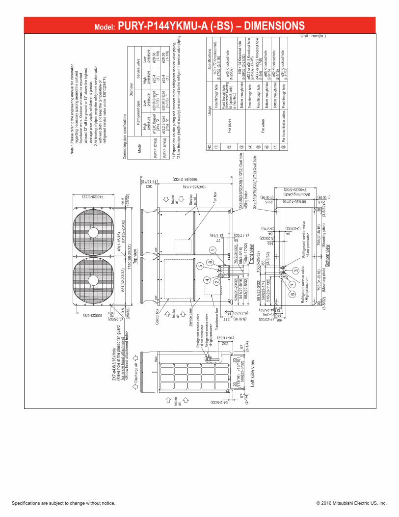
Model: PURY-P144YKMU-A (-BS) – DIMENSIONS
(2-9
/16)
(1-1
1/32
)
(2-1
/16)
(2-1
5/32
)
(1-3
/4)
(1-3
/8)
(5-2
9/32
)(3-2
3/32
)
(5-1
7/32
)(3-1
/16)
(1-2
5/32
)
(7/8
)
(1)
(1)
(1-1
/8)
(7/8
)
(3/4
)
(1-1
/8)
(1-1
/8)
(1-1
/8)
Fan
box
Note
1.P
leas
e re
fer t
o th
e en
gine
erin
g m
anua
l for
info
rmat
ion
rega
rdin
g ne
cess
ary
spac
ing
arou
nd th
e un
it an
d
fo
unda
tion
work
. Out
door
uni
t mus
t be
mou
nted
at
leas
t 12"
off
the
grou
nd o
r 12"
abo
ve th
e hi
ghes
t
av
erag
e sn
ow d
epth
, whi
chev
er is
gre
ater
.
2.At
bra
zing
of p
ipes
,wra
p th
e re
frige
rant
ser
vice
valve
wi
th w
et c
loth
and
kee
p th
e te
mpe
ratu
re o
f
re
frige
rant
ser
vice
valve
und
er 1
20°C
(248
°F).
Conn
ectin
g pi
pe s
pecif
icatio
ns<S
now
hood
atta
chm
ent h
ole>
2X7-
ø4.6
(3/1
6) H
ole(M
ake
hole
at th
e pla
stic f
an g
uard
for s
now
hood
atta
chm
ent)
Serv
ice p
anel
Refri
gera
nt se
rvice
valve
<Hi
gh p
ress
ure>
Refri
gera
nt se
rvice
valve
<Lo
w pr
essu
re>Co
ntro
l box
(Mou
ntin
g pi
tch)
(Mou
ntin
g pi
tch)
(Mounting pitch)
2X3-
14(9
/16)
X20(
13/1
6) O
val h
ole
Inta
keair Se
rvice
pane
l
Inta
keair
Inta
keair
Disc
harg
e ai
r
<Slin
g hole
>2X
2-80
(3-5
/32)X
35(1
-13/3
2) O
val h
ole
1
(25/
32)
(25/
32)
(2-25/32)(23-5/8)
(11-15/16)
(3-17/32)(3-1/16)
(3-5
/32)
(3-9
/32)
(4-25/32)
(7-23/32)
(5-23/32)
(3-5/16) (3-23/32)
(1-3/16)(26-13/16)
(3-5
/32)
(1-3/16)
(2-1
/4)
(2-1
/4)
(13/
16)
(13/
16)
(5-3/4)
(10-11/32)
Refri
gera
nt s
ervic
e va
lve <
Low
pres
sure
>Re
frige
rant
ser
vice
valve
<Hi
gh p
ress
ure>
5
8
67
3
24
(8-9/16)(5-23/32)
Tran
sform
er b
ox
Fron
t thro
ugh h
ole
Botto
m thr
ough
hole
Botto
m thr
ough
hole
Fron
t thro
ugh h
ole
Fron
t thro
ugh h
ole
For w
ires
ø52
Knoc
kout
hole
For t
rans
miss
ion ca
bles
ø34
Knoc
kout
hole
ø65
Knoc
kout
hole
Botto
m thr
ough
hole
150
× 94
Kno
ckou
t hole
140
× 77
Kno
ckou
t hole
Fron
t thro
ugh h
ole
NO.
For p
ipes
Fron
t thro
ugh h
ole(U
ses w
hen t
winn
ing
kit (o
ption
al pa
rts)
is mo
unted
.)
ø45
Knoc
kout
hole
Spec
ificat
ions
Usag
e
ø62.
7 or
ø34
.5 K
nock
out h
ole
ø43.
7 or
ø22
.2 K
nock
out h
ole
High
pres
sure
Low
pres
sure
High
pres
sure
Low
pres
sure
Serv
ice v
alve
*2 *2*1*1
Refri
gera
nt p
ipe
Diam
eter
ø25.
4
ø25.
4ø2
8.58
Bra
zed
PURY
-P144
YKMU
PURY
-P120
YKMU
ø22.
2 Br
azed
Mod
el
ø19.
05 B
raze
d
ø28.
58 B
raze
dø2
8.58
ø28.
58
*1 E
xpan
d th
e on
-site
pip
ing
and
conn
ect t
o th
e re
frige
rant
ser
vice
valve
pip
ing.
*2 U
se th
e pi
pe jo
int(f
ield
sup
ply)
and
con
nect
to th
e re
frige
rant
ser
vice
valve
pip
ing.
146
Top
view
Left
side
vie
w
Botto
m vi
ew
Fron
t vie
w
9484
516(
20-1
1/32
)
561(
22-3
/32)
150(
5-29
/32)
8359
0(23
-1/4
)
145
20
5758
6(23
-3/3
2)
20
57
54(2-5/32)49
(1-1
5/16
)
140(
5-17
/32)
68180
795(
31-5
/16)
795(
31-5
/16)
80
8977
740(29-5/32)
562(
22-5
/32)
29.5 29.5
(740)(29-5/32)
70600 19.5
831(
32-2
3/32
)83
1(32
-23/
32)
19.5
1750
(68-
29/3
2)
1650(64-31/32)
1347(53-1/16)303
121
196
262
526(
20-2
3/32
)
145217
541(
21-5
/16)
58(2
-5/1
6)75
(2-3
1/32
)
PURY-P120,144YKMUUnit : mm(in.)
1 2 4 5 6 7 83
Specifications are subject to change without notice. © 2016 Mitsubishi Electric US, Inc.
1340 Satellite Boulevard. Suwanee, GA 30024Toll Free: 800-433-4822 www.mehvac.com
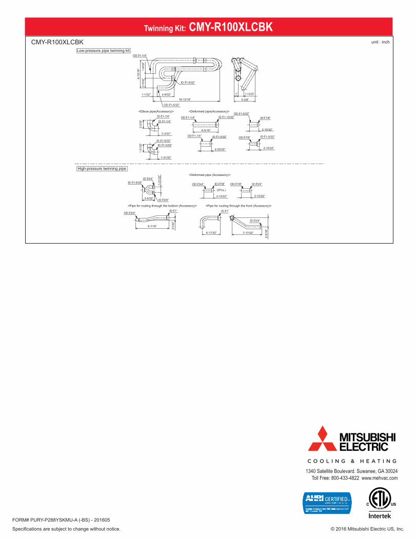
Twinning Kit: CMY-R100XLCBKunit : inch
<Pipe for routing through the front (Accessory)><Pipe for routing through the bottom (Accessory)>
<Deformed pipe(Accessory)><Elbow pipe(Accessory)>
<Deformed pipe (Accessory)>
(3Pcs.)
High-pressure twinning pipe
Low-pressure pipe twinning kit
CMY-R100XLCBK
OD 1-1/4”
ID 1-1/4”
ID 1-5/32”ID 1-5/32”
ID 1-5/32”ID 3/4”
ID 3/4”
ID 7/8” OD 7/8”
OD 3/4”
OD 3/4” ID 3/4”
ID 3/4”
ID 1” ID 1”
ID 1-1/4”
OD 1-5/32”
ID 1-5/32”
ID 1-5/32” ID 1-5/32”
OD 1-1/4”
OD 1-1/4”
ID 1-13/32” ID 7/8”
OD 7/8”
OD 1-5/32”
1-1/32”
1-31/32”
3-5/32”
8-7/16”
4-17/32”
1-31
/32”
21/3
2”
2-15/32”
7-17/32”
2-15/32”
2-5/
16”
2-3/32”6-5/16”
16-13/16”
1-13/32”
2-23/32”
2-15/32”
2-15/32”
1”
5-3/8”
4-9/32”
6-15
/16” 1-
9/32
”2-
15/3
2”2-
3/32
”1-
31/3
2”
FORM# PURY-P288YSKMU-A (-BS) - 201605