OTH: Viet Nam: Power Transmission Investment Program · PDF filePower Transmission Investment...
91
Power Transmission Investment Program (RRP VIE 42039 ) Feasibility Study Project Number: 42039-034 November 2011 Multitranche Financing Facility Socialist Republic of Viet Nam: Power Transmission Investment Program Summary Report 500/220 kV Bac Ninh 2– Pho Noi Transmission Lines
-
Upload
dangnguyet -
Category
Documents
-
view
215 -
download
0
Transcript of OTH: Viet Nam: Power Transmission Investment Program · PDF filePower Transmission Investment...

Power Transmission Investment Program (RRP VIE 42039)
Feasibility Study Project Number: 42039-034 November 2011
Multitranche Financing Facility Socialist Republic of Viet Nam: Power Transmission Investment Program
Summary Report 500/220 kV Bac Ninh 2– Pho Noi Transmission Lines

500/220kV Bac Ninh 2 - Pho Noi Transmission line Feasibility Study Summary Report
2
TABLE OF CONTENTS Chapter 1 : 3
NECESSITY AND OBJECTIVES OF THE PROJECT 3
1.1 Necessity of the project 3
1.2 Objective of the project 3
Chapter 2 : 4
PRESENT STATUS OF NORTH VIET NAM 4
2.1 Natural features and administration of the project area 4
2.2 Status of power system of the project area 4
2.3 Developing orientation of power sources and network 5
Chapter 3 : 9
LOAD FORECAST 9
3.1 Load forecast 9
3.2 Power flow calculation 11
Chapter 4 : 12
CONSTRUCTING SITE AND SCOPE OF THE PROJECT 12
4.1 Constructing site and the line route 12
4.2 Scope of Project 13
Chapter 5 : 14
TECHNICAL SOLUTIONS 14
5.1 Electrical solutions 14
Insulators 14
Calculation results 15
o Voltage of 220kV 15
o Voltage of 500kV 15
NOTE: Contamination level is 2.0cm/kV 15
5.2 Main construction solutions 16
Foundation solutions 16
Choosing materials 16

500/220kV Bac Ninh 2 - Pho Noi Transmission line Feasibility Study Summary Report
3
Chapter 1 :
NECESSITY AND OBJECTIVES OF THE PROJECT
1.1 Necessity of the project
Bac Ninh province is located in key economic areas - growth triangle: Ha Noi -
HaiPhong - Bac Ninh 2; near the area, the region's major industrial center in the North.
Because of such importance, provincial leaders and EVN (Electricity of VietNam) have attended to the construction of infrastructure, especially electricity.
According to the result of balanced power of Bac Ninh province, to meet the load demand in 2015, need to build 220kV Bac Ninh 2 substation with a capacity of 3x250MVA and 220kV Bac Ninh 3 substation with a capacity of 3x250MVA.
Therefore, the construction of transmission line 500/220kV Bac Ninh 2 – Pho Noi to power 220kV Bac Ninh 2 substation and associated 500kV grid northern region is needed.
1.2 Objective of the project
- Receiving power from 500/220kV Pho Noi substation and supplies power with
220kV Bac Ninh 2 substation to provide electricity for the Western – Southern
region of Bac Ninh province, and partial support for Bac Ninh city.
- Overload protection for 220kV & 110kV grids.
- Linking 500kV-220kV power grid in Northern region and ensuring national energy
security.
- Saving land in Bac Ninh province.

500/220kV Bac Ninh 2 - Pho Noi Transmission line Feasibility Study Summary Report
4
Chapter 2 :
PRESENT STATUS OF NORTH VIET NAM
2.1 Natural features and administration of the project area
Bac Ninh is a province in the northern delta region, fits in the Red River Delta, adjacent
to Hanoi.
- In the North : borders on Bac Giang province
- In the South : borders on Hung Yen province and a part of Hanoi
- In the East : borders on Hai Duong
- In the West : borders on Hanoi
Bac Ninh province has eight district-level administrative units, including Bac Ninh city
and seven districts of Bac Ninh is: Yen Phong, Que Vo, Tien Du, Tu Son, Thuan
Thanh, Gia Binh Luong Tai.
In recent years economic and social of Bac Ninh has made development, gross
domestic product GDP average growth of 12.9%. Structural economic shifts towards
industrialization.
2.2 Status of power system of the project area
Bac Ninh province is now mainly supply from national grid by regional transmission
grids and power stations as:
o Bac Ninh 220kV station is receiving power from Pha Lai Thermal Power
Plant by 220kV Pha Lai – Bac Ninh transmission line and from 220kV Soc
Son substation by 220kV Soc Son – Bac Ninh transmission line; and
supplies for 110kV substation as: Que Vo, Kinh Noi, Khac Niem, Tien Son,
Gia Luong, Binh Dinh, Vo Cuong and Dap Cau Glass.
o 110kV grid region is supported from sources surrounding the following:
From Pha Lai Thermal Power Plant by double circuit 110kV Pha Lai
- Bac Ninh transmission line, wire AC-150, 21.8 km.
From 220/110kV Dong Anh substation by double circuit 110kV
Dong Anh – Bac Ninh transmission line, wire AC-150, 35.8km.
From 220/110kV Dong Anh substation by single circuit 110kV Dong
Anh - Dinh Tram transmission line, wire AC-185, 36.8km.

500/220kV Bac Ninh 2 - Pho Noi Transmission line Feasibility Study Summary Report
5
Table 2-1: List of existing 220kV, 110kV transmission lines of the Bac Ninh area
No. Name of transmission
line Conductor Length (km) Note
I 220kV T/L
1 Pha Lai – Bac Ninh ACSR-520 24
2 Soc Son – Bac Ninh ACSR-520 46,1
II 110kVT/L
1 Bcc Ninh - Pha Lai ACSR-150 2x21,8
2 Gia Lương branch turn ACSR-185 1x8,0
3 Binh Đinh branch turn ACSR-185 1x9,2
4 Bac Ninh - Kinh Noi ACSR-150 2x9
5 Kinh Noi - Tien Son ACSR-150 2x6,5
6 Tien Son - Chau Khe ACSR-150 2x11,25
7 Chau Khe - Đong Anh ACSR-150 2x9
8 Đong Anh - Vo Cuong ACSR-185 1x22,5
9 Vo Cuong branch turn ACSR-185 1x3
10 Vo Cuong - Đap Cau ACSR-185 1x6,9
11 Đap Cau - Đinh Tram ACSR-185 1x8,2
Table 2-2: List of existing 220kV, 110kV substations of the Bac Ninh area
No. Name of substation Capacity (MVA) Note
1 220kV Bac Ninh 125+250
2 110kV Gia Luong 1x25
3 110kV Binh Đinh 1x63
4 110kV Kinh Noi 1x10
5 110kV Tien Son 40+63
6 110kV Que Vo 1x40
7 110kV Khac Niem 1x20
8 110kV Chau Khe 40+63
9 110kV Kinh Noi 1x10
10 110kV Vo Cuong 3x25
11 110kV Đap Cau 1x6,3
2.3 Developing orientation of power sources and network
Based on "Plan for National Electricity Development for 2006-2015, with perspective to
2025 (overall scheme VI)" was approved by the Prime Minister and "Planning the

500/220kV Bac Ninh 2 - Pho Noi Transmission line Feasibility Study Summary Report
6
improvement and development of grid Bac Ninh power 2008-2010 period, considering
that by 2015” was approved by the Ministry of Industry and Trade, plans to develop
regional power grid and Bac Ninh in the period 2008-2010 and in 2011-2015 as follows:
Table 2-3: Developing orientation for 220kV, 110kV T/L of Bac Ninh (2015)
No. Project Conductor
Scale
2008-2010 2010-2015
I 220kV T/L
Bac Ninh 3 branch turn AC-2x330 2 x 7km
Long Bien - Bac Ninh 2 AC-500 2x28,5km
II 110kV T/L
1 Bac Ninh - Tien Son AC-240 2x27km
2 Bac Ninh - Đai Kim - Bac Giang AC-300 2x20km
3 Yên Phong branch turn AC-300 2x8km
4 Yen Phong - Yen Phong 2 AC-300 2x7km
5 Thuan Thanh 2 branch turn AC-240 2x4,5km
6 VSIP branch turn AC-240 2x3km
7 Que Vo 2 branch turn AC-185 2x1km
8 Khac Niem branch turn AC-185 2x0,5km
9 Thuan Thanh 2 - Thuan Thanh 3 AC-240 2x7km
10 Hanaka branch turn AC-300 2x5km
11 Binh Đinh - Hung Yen AC-240 2x12km
12 220kV Bac Ninh 2 substation feeder AC-240 6x0,2km
13 220kV Bac Ninh 3 substation feeder AC-300 4x0,5km
14 Bac Ninh 3 - Yen Phong AC-300 2x7km

500/220kV Bac Ninh 2 - Pho Noi Transmission line Feasibility Study Summary Report
7
Table 2-4: Developing orientation for 220kV, 110kV substation of Bac Ninh (2015)
No. Project
Scale (MVA)
2008-2010 2010-2015
I 220kV substation
New construction
1 220kV Bac Ninh 2 2x500
2 220kV Bac Ninh 3 2x500
Improved capacity
220kV Bac Ninh 2x500
II 110kV substation
New construction
1 110kV Yen Phong 1x63 1x63
2 110kV Yen Phong 2 1x63 1x63
3 110kV Đai Kim 1x63 1x63
4 110kV VSLP 1x63 1x63
5 110kV Thuan Thanh 2 1x40 1x40
6 110kV Que Vo 2 1x40 1x40
7 110kV Khac Niem 1x63 1x63
8 110kV Thuan Thanh 3 1x63 1x63
9 110kV Bac Ninh 2 1x63
10 110kV Hanaka 1x63
Improved capacity
1 110kV Chau Khe 1x63
2 110kV Vo Cuong 2x80

500/220kV Bac Ninh 2 - Pho Noi Transmission line Feasibility Study Summary Report
8
3 110kV Gia Luong 1x25 1x40
4 110kV Binh Đinh 1x63
5 110kV Que Vo 1x40 1x63
6 110kV Tien Son 1x63

500/220kV Bac Ninh 2 - Pho Noi Transmission line Feasibility Study Summary Report
9
Chapter 3 :
LOAD FORECAST
3.1 Load forecast
Based on topography, existing economic partitions and economic development plans of
the Bac Ninh province, there are 2 load zone as follows:
Zone 1: comprises Bac Ninh city, Yen Phong district, Tu Son district, Tien Du district
and Que Vo district.
Zone 2: comprises Thuan Thanh district, Luong Tai district and Gia Binh district.
Zone 1 is now supplied power from 110kV Vo Cuong substation and 110kV Dap Cau
substation. Zone 2 is now supplied from 110kV Gia Luong substation and 110kV Binh
Dinh substation.
Based on "Planning the improvement and development of grid Bac Ninh power 2008-
2010 period, considering that by 2015” was approved by the Ministry of Industry and
Trade, power demand of each area as follows in table 3-1:

500/220kV Bac Ninh 2 - Pho Noi Transmission line Feasibility Study Summary Report
10
Table 3-1: Load data of each area
No. Name of area
Industrial &
Construction
Agriculture,
Forestry &
Fisheries
Trade & Service Sector management Others Pmax (kW)
2010 2015 2010 2015 2010 2015 2010 2015 2010 2015 2010 2015
1 BacNinh city 16.400 27.630 1.110 1.280 2.620 4.930 23.910 34.780 5.040 8.060 35.790 60.620
2 Yen Phong district 84.880 191.59 2.110 2.540 2.540 1.200 20.420 27.550 1.120 3.260 93.330 209.900
3 Tu Son district 95.350 187.450 3.170 3.580 310 4.480 36.300 52.620 9.400 14.420 111.920 226.580
3 Tien Du district 81.480 188.150 1.370 1.690 870 1.330 19.790 28.660 2.340 7.160 89.930. 208.740
5 Que Vo district 98.180 206.820 2.030 2.350 320 1.950 14.070 23.690 1.230 4.040 104.120 223.430
6 Thuan Thanh district 33.170 111.940 660 890 320 960 18.210 28.230 860 2.450 40670 130.240
7 Gia Binh district 2.170 22.715 1.360 1.690 150 500 10.610 16.030 720 1.690 12.570. 33.030
8 Luong Tai district 50.660 94.520 1.810 2.230 310 920 17.300 48.990 690 1580 57.780 124.910
Pmax(kW) 392.000 930.00 13.000 15.000 5.000 15.500 140.000 217.000 19.500 38.700 490.000 1.075.000

500/220kV Bac Ninh 2 - Pho Noi Transmission line Feasibility Study Summary Report
11
3.2 Power flow calculation
According to the load flow calculation in 2025, the transmitted power through
500/220kV Bac Ninh 2 - Pho Noi TL such as:
220kV voltage: Smax = 765.4 + j415.8 (MVA)
500kV voltage: Smax = 990.9 + j198.7 (MVA)

500/220kV Bac Ninh 2 - Pho Noi Transmission line Feasibility Study Summary Report
12
Chapter 4 :
CONSTRUCTING SITE AND SCOPE OF THE PROJECT
4.1 Constructing site and the line route
The 500/220kV Bac Ninh 2 – Pho Noi transmission line has total length about 30.5km.
The start point is at the 500/220kV Pho Noi substation and end point is at the
220/110kV Bac Ninh 2 substation.
This transmission line passes through 2 provinces: Bac Ninh and Hung Yen.
In Bac Ninh province, length of line route is about 29.3km, and passes through 4
district: Thuan Thanh, Gia Binh, Que Vo, Tien Du.
In Hung Yen province, length of line route is about 1.2km, and passes through Van
Lam district.
Generally full of 500/220kV Bac Ninh 2 – Pho Noi transmission line passes through flat
country terrain which is planting rice and farm produce of Bac Ninh and Hung Yen
province.
This transmission line has 1 crossing wide, Duong river.
The line route is described in table 4-1 as following:
Table 4-1: The number of basic data of 500/220kV Bac Ninh 2 – Pho Noi transmission
line.
No. ITEMS UNIT NUMBERS
1 1 The length of line km 30.5
2 2 Total steering angle angle 26
3 Number of crossing with Highway No.38 times 02
4 Number of crossing with provincial road 282 times 01
5 Number of crossing with provincial road 284 times 01
6 Number of crossing with communal road times 77
7 Number of crossing with Duong river dike times 01
8 Number of crossing with Duong river times 01
9 Number of crossing with canal, width <10m times 63
10 Number of crossing with canal, width >10m times 14
11 Number of crossing with pond, width <100m times 04
12 Number of crossing with pond, width >100m times 05
13 Number of crossing 500kV TL times 01

500/220kV Bac Ninh 2 - Pho Noi Transmission line Feasibility Study Summary Report
13
No. ITEMS UNIT NUMBERS
14 Number of crossing 110kV TL times 02
15 Number of crossing 0.4÷35kV TL times 11
16 Length of TL passes through land for planting crops km 3
17 Length of TL passes through paddy land km 27,5
18 Number of house in transmission corridor house 02
4.2 Scope of Project
The scope of the project is includes building the 500kV single circuit and 220kV double
circuit transmission line on the same pole.
- Voltage: 500kV & 220kV
- Number of Circuits: 01 (500kV) & 02 (220kV)
- Start point: 500kV Pho Noi substation.
- End point: 220kV Bac Ninh 2 substation.
- Total length: 30.5 km.
- Conductor: 4×ACSR330/42 (500kV) & 3×ACSR400/51 (220kV); at the crossing
Duong river, using: 4×ASTER-366 & 3×AAAC-400
- Overhead Ground Wires: PHLOX-147 & OPGW-120
- Insulator: U70BL, U120B, U160BS, U300B suspension and tension insulator sets.
- Tower: galvanized steel tower.
- Foundation: Raft foundation made from steel concrete in - situ cast.
- Grounding: directly by 12mm dia galvanized round iron bar combined with
galvanized earth-electrode.

500/220kV Bac Ninh 2 - Pho Noi Transmission line Feasibility Study Summary Report
14
Chapter 5 :
TECHNICAL SOLUTIONS
5.1 Electrical solutions
5.1.1 Selection of Voltage level
The voltage level has to be selected based on the duty of the line within the network
and network planning. Selected voltage levels are based on Vietnamese standard
voltage levels:
- Super high voltage level: 500kV.
- High voltage levels: 220kV, 110kV.
- Medium voltage level: 22kV.
According to the power distribution calculation and transmission distance, voltage level
is selected 500kV & 220kV.
5.1.2 Selection of Conductor
Conductor are selected according to electrical, thermal, mechanical and economic
aspected.
In accordance with the result of calculation power flow, the cross-section of conductor
used for 500/220kV Bac Ninh 2 – Pho Noi transmission line is 4 × ACSR 330/42
(550kV) and 3 × ACSR 400/51 (220kV).
5.1.3 Selection of Overhead Ground Wires
To satisfy requerements of lightning protection of 500/220kV Bac Ninh 2 – Pho Noi
transmission line and link optical communication, used two ground wires above the
power lines: PHLOX and OPGW (Composite Fiber Optic Overhead Ground Wire).
Caculated cross-section [mm2] of Overhead Ground Wires be selected by taking the
limits of temperture rise caused by short-circuited transmission lines.
In accordance with the result of calculation one phase fault, the kinds of Overhead
Ground Wires are selected are PHLOX-147 and OPGW120/24 SM-fibres.
5.1.4 Selection of Insulators and Accessories
Insulators
To satisfy mechanical failing load, insulators of transmission line be used types below:
U70BL, U120B, U160BS, and U300B

500/220kV Bac Ninh 2 - Pho Noi Transmission line Feasibility Study Summary Report
15
Glass or porcelain insulator is used for insulator string type. As countermeasure
against corrosion of the pin, each insulator shall be armored with a zinc sleeve around
the pin shank.
Insulators and fittings must be manufactured in accordance with international standard
IEC-305.
Number of insulators per string is calculated in accordance with nominal creepage
distance.
Calculation results
o Voltage of 220kV
No. Insulator Sign Quantity
1 Single suspension insulator string CĐ 12-1-17 1x17
2 Single suspension insulator string CĐ 16-1-16 1x16
3 Double suspension insulator string CĐVĐ 12-2-18 2x18
4 Double suspension insulator string CĐVĐ 16-2-17 2x17
5 Double suspension insulator string CĐVVS 30-2-17 2x17
6 Double tension insulator string CN 12-2-18 2x18
7 Double tension insulator string CN 30-2-14 2x14
8 Single jumper suspension insulator string CĐL 7-1-17 1x17
o Voltage of 500kV
No. Insulator Sign Quantity
1 Single suspension insulator string CĐ 12-1-37 1x37
2 Double suspension insulator string CĐV 12-2-38 2x38
3 Double suspension insulator string CĐV 16-2-36 2x36
4 Double suspension insulator string CĐVVĐ 16-2-36 2x36
5 Double suspension insulator string CĐVVĐ 30-2-29 2x29
6 Double suspension insulator string CĐVVS 30-2-34 2x34
7 Double tension insulator string CN 16-2-35 2x35
8 Double tension insulator string CN 30-2-29 2x29
9 Double tension insulator string CN 30-2-31 2x31
10 Single jumper suspension insulator string CĐL 7-1-37 1x37
NOTE: Contamination level is 2.0cm/kV
5.1.5 Protection solutions
Lightning protection: To reduce of lightning directly striking overhead transmission
lines, used two ground wires above the power lines with protect angles 20.

500/220kV Bac Ninh 2 - Pho Noi Transmission line Feasibility Study Summary Report
16
Earthing: Directly grounded GSW conductor at all tower, gantry and tower themselves.
Damper:
Stockbridge vibration dampers are used on ground wires.
5.2 Main construction solutions
5.2.1 Design of the Towers
All towers of 500/220kV Bac Ninh 2 – Pho Noi transmission line are designed as self-
supporting structure, steel latticed towers type.
Types of basic tower is used for this project are suspension and tension towers.
- The height of suspension towers : 41.5m; 67m, 71m, 77m; 34m, 38m; 57.5m,
61.5m, 69.5m, 73.5m; 102m.
- The height of tension towers : 23.5m, 30m, 40m, 56m; 62m; 34m; 47m, 59m,
64m; 47m, 59m.
5.2.2 Design of the foundation
Foundation solutions
Engineering-geology, relief, hydrology along line route is the same kind of relative
identical land, so choosing pad-and-chimney foundations are logical and economical.
Choosing materials
The foundations steel uses for group A. The steel A1 is Rs=2250kg/cm2, the steel A2 is
Rs=2800kg/cm2 and the steel A3 is Rs=3650kg/cm2. Foundations will be reinforced
concrete, in situ cast with 2x4 stones, concrete grade M200. The pave under
foundations, in situ cast with 4x6 stones, concrete grade M50.
Power Transmission Investment Program (RRP VIE 42039)
Feasibility Study Project Number: 42039-034 November 2011
Multitranche Financing Facility Socialist Republic of Viet Nam: Power Transmission Investment Program
Summary Report Pho Noi 500 kV Substation and Connecting Lines

Pho Noi 500kV Substation & Connecting Branches Feasibility Study Summary Report
2
TABLE OF CONTENTS
Chapter1 : General Introduction .......................................................................................... 3
Chapter2 : Necessity Of Project Investment ....................................................................... 4
Chapter3 : Selecting Substation Contruction Location ...................................................... 16
Chapter4 : Main Technological Solutions ............................................................................ 17
Chapter5 : Main Solutions Applied For Civil Construction Part ........................................... 20
Chapter6 : Solution Applied For Connecting Branches ....................................................... 23
Chapter7 : Solution For Substation Service Power Supply Transmission Line ................... 25
Chapter8 : Solution Applied For Telecommunication .......................................................... 26

Pho Noi 500kV Substation & Connecting Branches Feasibility Study Summary Report
3
CHAPTER 1: GENERAL INTRODUCTION
1.1. BASIS OF ESTABLISHED FESIBILITY STUDY
Feasibiltiy Study (FS) for 500kV Pho Noi substation and connecting branches project is
established based on the following basis:
Master Plan of Power Sector Development of Vietnam No. VI.
Plan of power network improvement and development of Hung Yen province, period
of 2006-2010 perspective to 2015.
Correspondence to No. 6195/CV-EVN-KH dated 21/11/2007 of Viet Nam Electricity
about “Assigning establish feasibility study for 500kV Pho Noi substation and
connecting branches project”.
Correspondence to No. 653/UBND-KTTH dated 29/04/2008 of Hung Yen province
people’s committee about “Agree local construction for 500kV Pho Noi substation and
connecting branches project”.
Contract between Northern Power Project Management Board and Power
Engineering Consulting Joint Stock Company 4.
1.2. OBJECTIVES OF PROJECT
Investment of 500kV Pho Noi substation and connecting branches project aims to:
Connecting and transmitting power capacity from Hai Phong 3 Thermal Power
Complex aim to load demand of Nothern region in general and national.
Create a ring circuit connection of 500kV Pho Noi – Dong Anh – Hiep Hoa, aim to
load demand of Ha Noi center.
Increase realibity and safety of power supply and power quality to power grid of
Nothern region in general and national.

Pho Noi 500kV Substation & Connecting Branches Feasibility Study Summary Report
4
CHAPTER 2 : NECESSITY OF PROJECT INVESTMENT
To explain the necessity and the construction time of 500kV Pho Noi substation, the
project shall be analysed by focusing on 2 factors:
The facilitation for the connection and power transmission between Hai Phong 3
Thermal Power Complex and The National Power System.
The guarantee of continuous power supply and safe operation in all cases of the
system for the load demand of Hung Yen province and neighboring provinces.
To find the most reasonable way of connecting Hai Phong 3 Thermal Power Complex
into the National Power System, this project shall focus on:
Power balance, load balance in Ha Noi and neighboring provinces including Ha Tay,
Ha Nam, Hung Yen, Hai Duong, Bac Ninh, Vinh Phuc and Phu Tho.
The study of current status and expected development of electricity transmission grid
in the project area to propose the connection plan.
2.1. POWER BALANCE AND LOAD BALANCE IN THE AREA
Table 2.1: Power balance, load balance in Ha Noi and neighboring provinces
No. Description Year 2010 Year 2015 Year 2020
1 Total power in the area (MW) 3.220 3.220 4.420
2 Total power load (MW) 3.937 7.809 12.749
3 Balance, residual (+), insufficient (-) -717 -4.589 -8.392
Source: Plan for connecting all thermoelectric plants in the whole country to the National Power System.

Pho Noi 500kV Substation & Connecting Branches Feasibility Study Summary Report
5
Figure 2.1: Power and load balancing in the North area in 2015
Figure 2.2: Power and load balancing in the North area in 2020
-G: 3200MW
-D: 7800MW
-Balanced:-4600MW
-G: 9400MW
-D: 3500MW
-Balanced:+5900MW
5900MW
-G: 6000MW
-D: 2200MW
-Balanced:+3800MW
3800MW
-G: 600MW
-D: 1400MW
-Balanced: -800MW
-G: 6200MW
-D: 2700MW
-Balanced: +3500MW
3500MW
-G: 9300MW
-D: 6200MW
-Balanced: +3100MW
-G: 10400MW
-D: 4600MW
-Balanced: +5800MW
-G: 4400MW
-D: 1270MW
-Balanced: -8300MW
3100MW
-G: 7200MW
-D: 3700MW
-Balanced: +3500MW
3500MW
-G: 2800MW
-D: 2400MW
-Balanced: -400MW
5800MW
North-Western
North-Eastern
Ha Noi and neighboring
Southern Ha Noi North of Central
North-Western
North-Eastern
Ha Noi and neighboring
Southern Ha Noi North of Central

Pho Noi 500kV Substation & Connecting Branches Feasibility Study Summary Report
6
2.2. ALTERNATIVES FOR CONNECTING HAI PHONG 3 THERMAL POWER COMPLEX
TO THE NATIONAL POWER SYSTEM
2.2.1 Connection Alternatives:
Hai Phong 3 Thermal power complex is proposed to be put in operation in stage 2014 -
2015 with the following power capacity and operating schedule:
Table 2.2: Operating schedule of Hai Phong 3 Thermal power complex
No. Generator Power Capacity
(MW) Operating
year
1 Generator 1 and 2 1200 2014
2 Generator 3 and 4 1200 2015
With the main purpose of Hai Phong 3 Thermal Power Complex power transmission
which supplies the load demand in Ha Noi and neighboring provinces, this project shall
consider 2 connection alternatives as below:
Alternative 1: Build Pho Noi 500kV substation at Van Lam district, Hung Yen province
and the substation shall be connected to the existing Quang Ninh – Thuong Tin 500kV
transmission line.
Figure 2.3: 500kV power network in the North area until 2020 - Alternative 1
To execute plan 1, it is necessary to completely build 500kV power
network until 2020 as below:
- Build Pho Noi 500kV substation: 2x600MVA.
- Build 500kV transmission line, double circuits, approximate 1.34km in
: substation in operating up to 2015 : substation in operating up to 2020
THAI NGUYEN
HIEP HOA
BAC GIANG
BAC NINH
VIET TRI
VINH YEN
DONG ANH
HOA BINH
NHO QUAN
THUONG TIN PHO NOI
THAI BINH
NĐ THAI BINH 1800MW
NĐ MÔNG DƯƠNG 2200MW
NĐ QUẢNG NINH 1200MW
NĐ HẢI PHÒNG III 2400MW
NĐ HẢI PHÒNG I, II 1200MW
SON LA
TĐ TICH NANG 1200MW
THANH HOA
: substation in operating stage up to 2010
: line in operating stage up to 2015
: line in operating stage up to 2010
: line in operating stage up to 2020
HOAI ĐUC
NĐ THĂNG LONG

Pho Noi 500kV Substation & Connecting Branches Feasibility Study Summary Report
7
length which shall connect Pho Noi 500kV substation to Quang Ninh – Thuong Tin
500kV transmission line by conductor 4xACSR330.
- Build 500kV transmission line, approximate 58km in length which shall connect Hai
Phong 3 Thermal power complex to Pho Noi 500kV substation.
- Build 500kV transmission line, approximate 60km in length which shall connect Thai
Binh 500kV substation to Pho Noi 500kV substation.
- Build 500kV transmission line, approximate 35km in length which shall connect Dong
Anh 500kV substation to Pho Noi 500kV substation.
Alternative 2: Hai Phong 3 Thermal power complex shall be connected to Thuong Tin
500kV substation.
Figure 2.4: 500kV power network in the North area until 2020 - Alternative 2
To execute alternative 2, it is necessary to completely build 500kV power network until
2020 as below:
- Install 900MVA transformer at 500kV Thuong Tin substation.
- Build 500kV transmission line, approximate 80km in length which shall connect Hai
Phong 3 Thermal power complex to Thuong Tin 500kV substation.
- Build 500kV transmission line, approximate 72km in length which shall connect Thai
Binh 500kV substation to Thuong Tin 500kV substation.
- Build 500kV transmission line, approximate 45km in length which shall connect Dong
Anh 500kV substation to Thuong Tin 500kV substation.
THÁI NGUYÊN
HIỆP HOÀ
BẮC GIANG
BẮC NINH
VIỆT TRÌ
VĨNH YÊN
ĐÔNG ANH
HOÀ BÌNH
NHO QUAN
THƯỜNG TÍN
THÁI BÌNH
NĐ THÁI BÌNH 1800MW
NĐ MÔNG DƯƠNG 2200MW
NĐ QUẢNG NINH 1200MW
NĐ HẢI PHÒNG III 2400MW
NĐ HẢI PHÒNG I, II 1200MW
SƠN LA
TĐ TÍCH NĂNG 1200MW
THANH HOÁ
: substation in operating stage up to 2010
: line in operating stage up to 2015
: line in operating stage up to 2010
: line in operating stage up to 2020
HOÀI ĐỨC
: substation in operating stage up to 2015 : substation in operating stage up to 2020
NĐ THĂNG LONG

Pho Noi 500kV Substation & Connecting Branches Feasibility Study Summary Report
8
-
2.2.2 Calculate power distribution and define power loss of electricity grid
Table 2.3: Power loss of entire system of alternatives
No. Alternative Power Loss (MW)
Year 2015 Year 2020
1 Alternative 1 (PA1) 837 1696
2 Alternative 2 (PA2) 852 1741
(PA2 - PA1) 15 45
Pmax:
Losses: 837MW
42240MW
Heä thoáng ñieän 500kV Mieàn Baéc naêm 2015
Cheá ñoä phuï taûi cöïc ñaïi
Phöông aùn 1
Töø Vuõng AÙng 3600+j123.2
Ñi Ñaø Naüng
Thanh Hoaù
NÑ. Nghi Sôn
Vuõng AÙng 1, 2
Haø Tónh
Huoäi QuaûngSôn La Lai Chaâu
Naâm Chieán
Hoaø Bình
Baéc Ninh
Ñoâng Anh
Hieäp Hoaø
Vieät Trì
Hoaøi Ñöùc
Nho Quan
Thöôøng Tín
Phoá Noái
NÑ.Haûi Phoøng 3
NÑ Th.Long
NÑ.MDöông
Q.Ninh
NÑ. QNinh
600+j123.22x(
2x(600+j69.9
413.8+j498.6
536+j95.2
627.2+j231.4
768.2+j128
1599.4+j288.6
248.5-j235.3
3x(250+j61.7
2x(600+j360.0
1199.4+j605
600+j17.3400+j97.52x(
2x(400+j97.5
973.1+j444.8
1161.2+j517.8
-234.4+j332.3
285.4-j377
725+j445.4
139.4+j50.1
788.6+j235.7
-67.1+j138.7
739.2-j9.9
441.8-j13.5
728+j137.3
713.6+j460.2
-284.8+j78.5
684+j529.41406.8+j435.2
945+j618.6
905.2+j201.8
51.2-j137.7
-118.9+j69.1
245.9+j72.0
950.2+j501.8
335+j321
2236.6+j759.6
300-j240
140+j113.910x(
719.8-j224 8x(90+j10.9
223.4kV
-63.6-j20.1
235.2kV
517.2kV
258.9-j109.7
518.2kV
231.2kV
1633.8-j139.6
-93.2+j478
230.0kV
-1106.3+j110.8
522.0kV 920.4+j171.6
394+j413.3507.4kV
230.6kV
343-j94.4
511.6kV
519.9kV228.0kV
506.5kV
511.2kV
-515.8+j172.7
522.5kV
524.8kV
225.6kV
222.5kV
504.5kV
Pitoong
225.5kV
521.8kV
497.4kV490.8kV
218.0kV
224.6kV
217.5kV
508.4kV
221.3kV
496.9kV
231.3kV
493.3kV
515.2kV
224.8kV
518.1kV
Figure 2.5: Load flow of 500kV power network in the North area in 2015 - Alternative 1

Pho Noi 500kV Substation & Connecting Branches Feasibility Study Summary Report
9
Pmax:
Losses: 852.3MW
42240MW
Heä thoáng ñieän 500kV Mieàn Baéc naêm 2015
Cheá ñoä phuï taûi cöïc ñaïi
Phöông aùn 2
Töø Vuõng AÙng 3600+j125.2
Ñi Ñaø Naüng
Thanh Hoaù
NÑ. Nghi Sôn
Vuõng AÙng 1, 2
Haø Tónh
Huoäi QuaûngSôn La Lai Chaâu
Naâm Chieán
Hoaø Bình
Baéc Ninh
Ñoâng Anh
Hieäp Hoaø
Vieät Trì
Hoaøi Ñöùc
Nho Quan
Thöôøng Tín
NÑ.Haûi Phoøng 3
NÑ Th.Long
NÑ.MDöông
Q.Ninh
NÑ. QNinh
600+j125.22x(
2x(600+j72.2
413.6+j498
512.8+j112.6
1599.4+j333
288.8-j233.4
3x(250+j63.2
2x(600+j342.1
1199.6+j573.6
600+j22.1400+j108.92x(
2x(400+j108.9
1037.9+j447.8
1707.6+j683.8
-232.1+j338.0
256.6-j386.2
723+j437.6
74.2+j49.9
843.3+j261.9
-28.6+j147.9
674.1-j4.8
376.3-j12.7
763.7+j156.0
805.6+j480
-262.6+j108.6
770.5+j555.7
1484+j457
885.8+j590
923.2+j211.6
24.6-j141.2
-158.9+j72.8
247.8+j73.6
890.4+j468.2
438.4+j379.2
2301.4+j802
300-j231.8
140+j116.710x(
719.8-j214.4 8x(90+j12.1
223.4kV
-67.4-j18.9
235.1kV
517.0kV
259.6-j109.4
518.1kV
231.2kV
1647.6-j136.6
-107.8+j480.6
230.0kV
-1115.8+j111.3
521.8kV 924+j174.7
394.1+j411.2507.1kV
230.5kV
343.2-j94.2
510.6kV
524.5kV226.1kV
505.8kV
510.8kV
-519.2+j168.6
522.2kV
524.6kV
225.7kV
221.6kV
503.1kV
Pitoong
225.1kV
521.0kV
494.9kV490.2kV
218.0kV
223.2kV
219.1kV
494.1kV
229.5kV
490.4kV
514.0kV
224.4kV
517.2kV
Figure 2.6: Load flow of 500kV power network in the North area in 2015 – Alternative 2
489.6-j452.4
Ñi Ñaø Naüng
451.4-j126.4
1654.8+j529.8
514.7kV
TÑ Tích Naêng
Heä thoáng ñieän 500kV Mieàn Baéc naêm 2020
Cheá ñoä phuï taûi cöïc ñaïi
Phöông aùn 1
623.8+j55.8
217.8kV
501.2kV623.2+j111.8
Vónh Yeân
4x(300+j153.8
475.4-j52.2
1117.4-j57.9
Tr.Quoác
1500+j300
224.5kV
492.3kV
646.4+j322
645+j397.5 Thaùi Nguyeân
800.2+j277.6
220.5kV
500.6kV
488.5+j11.2
Baéc Giang
227.1kV
443.8+j517.8
495.5kV
28.8-j465.8
Thaùi Bình
Ñi Vuõng AÙn 3
Thanh Hoaù
NÑ. Nghi Sôn
Vuõng AÙng 1, 2
Haø Tónh
Sôn La
Lai Chaâu
Naâm Chieán
Hoaø Bình
Baéc Ninh
Ñoâng Anh
Hieäp Hoaø
Vieät Trì
Hoaøi Ñöùc
Nho Quan
Thöôøng Tín
Phoá Noái
NÑ.Haûi Phoøng 3
NÑ Th.Long
NÑ.MDöông
Q.Ninh
NÑ. QNinh
500-j79.62x(
2x(600+j86.4
316.6+j265.0
1331-j91
356.6+j243.2
1405.4+j450.2
2199.8+j287.8
238-j305.6
3x(300+j113.0
2x(600+j360.0
1199.8+j622.2
600+j339.5
600+j107.22x(2x(500+j101.7
1020.2+j196.6
1679.2+j326.2
498.2+j76.5
626.8+j299.4
894.8+j473.4
337.6-j29.6
575+j121.8
936.9+j343.2
633.8+j133.7
1884.4+j370.6
799+j327.2
278.5+j137.3
1294.6+j341.4
1551.4+j195623+j248.6
1232.6+j615.8
1134.5+j397.7
553.6-j26.1
-34.8+j6.5
1258.6+j104.8
408.8-j29.8
1731.6-j25
220+j64.910x(
1198.8-j460 5x(240-j80
224.2kV
180-j136.5
234.3kV
509.4kV
354.4+j548.8514.7kV
231.7kV
1575.4+j78.8
1420.8+j374.4
230.8kV
752.7-j143.2
511.2kV 777.1+j139.2
926+j433.6
498.5kV
231.5kV
602.2+j16.6
70587MW
1696MWLosses:
Pmax:
516.0kV
514.4kV219.3kV
498.4kV
500.4kV
511.6kV
505.2kV219.6kV
230.4kV
498.7kV
Pitoong
228.8kV
520.9kV
497.5kV
502.4kV
213.8kV
217.1kV
215.5kV
502.2kV
220.3kV
496.1kV
223.4kV
497.4kV 517.0kV
222.1kV
520.1kV
Figure 2.7: Load flow of 500kV power network in the North area in 2020 – Alternative 1

Pho Noi 500kV Substation & Connecting Branches Feasibility Study Summary Report
10
467.8-j433.4
Ñi Ñaø Naüng
517.5-j55.1
1678.6+j627.2
513.2kV
TÑ Tích Naêng
Heä thoáng ñieän 500kV Mieàn Baéc naêm 2020
Cheá ñoä phuï taûi cöïc ñaïi
Phöông aùn 2
665.6+j77.8
216.1kV
498.7kV664.8+j132.1
Vónh Yeân
4x(300+j175.1
529+j17.7
1349.1-j155.4
Tr.Quoác
1500+j300
222.3kV
488.3kV
694.6+j336
693.1+j408.0
Thaùi Nguyeân
988.6+j371.2
217.8kV
496.1kV
591+j41.8
Baéc Giang
226.4kV
534.1+j535.0
494.7kV
-8.6-j420.4
Thaùi Bình
Ñi Vuõng AÙn 3
Thanh Hoaù
NÑ. Nghi Sôn
Vuõng AÙng 1, 2
Haø Tónh
Sôn La
Lai Chaâu
Naâm Chieán
Hoaø Bình
Baéc Ninh
Ñoâng Anh
Hieäp Hoaø
Vieät Trì
Hoaøi Ñöùc
Nho Quan
Thöôøng Tín
NÑ.Haûi Phoøng 3
NÑ Th.Long
NÑ.MDöông
Q.Ninh
NÑ. QNinh
500-j111.62x(
2x(600+j265.7
340+j290.1
1216.4-j79.8
2199.8+j323.6
364-j260
3x(300+j114.0
2x(600+j360.0
1199.8+j621.8
600+j284.4
600+j116.42x(2x(500+j110.8
996.4+j206.3
2613+j663.9
462+j32.9
634.8+j319.2
930.8+j513.4
163.9-j85.9
499.2+j73.4
763.7+j238.7
461.2+j47.4
2105+j505
986.8+j412.4
-70.6-j32.2
921.4+j183.8
1758+j307600.7+j241.9
1274+j693.4
1105.9+j368.8
530.9-j50.1
-28.3+j6.1
1278.6+j127.4
390.4-j21.61776.4+j24.2
220+j64.510x(
1198.8-j460 5x(240-j80
224.3kV
115.8-j260.1
234.7kV
512.8kV
263.2+j510.1516.4kV
228.8kV
1465.6-j1.4
1197.6+j336.6
231.1kV
661.6-j132.5
526.4kV 715.5+j346.7
961+j409.6
503.1kV
230.9kV
599.4+j37.6
70587MW
1741MWLosses:
Pmax:
517.5kV
513.0kV213.4kV
500.7kV
502.8kV
511.6kV
506.2kV219.5kV
230.7kV
495.1kV
Pitoong
228.8kV
521.0kV
493.8kV
500.1kV
213.0kV
214.1kV
215.1kV
494.0kV
219.2kV
492.0kV 516.3kV
223.1kV
519.6kV
Figure 2.8: Load flow of 500kV power network in the North area in 2020 – Alternative 2
Table 2.4: Cases of calculation at maximum load in 2015
No Case 220kV Transmission Line
or 500kV Substation
Power load in line or
transformer
Load percentage
Power loss of VN power
system.
A Alternative 1
1 In normal case
Thuong Tin - Mai Dong (1 circuit)
249+j76.5 72%
837 MW
Mai Dong - An Duong (1 circuit)
91.5+j6.7 25%
Thuong Tin - Van Dien (1 ciruit)
119+j87 41%
Thuong Tin - Pho Noi 12-j11.1 6%
Pho Noi 500kV substation 768+j128 65%
Thuong Tin 500kV substation 1,161+j517 94%
B Alternative 2
1 In normal case
Thuong Tin - Mai Dong (1 circuit)
297+j104.5 87%
852.3MW
Mai Đong - An Duong (1 circuit)
139.5+j70.3 43%
Thuong Tin – Van Đien (1 circuit)
172+j107.9 69%
Thuong Tin - Pho Noi 193-j5.3 65%
Thuong Tin 500kV substation *
1,707+j683 136%
(*) : Thuong Tin 500kV substation with power at (450+900)MVA (as Master Plan VI)
Pho Noi 500kV Substation & Connecting Branches Feasibility Study Summary Report
11
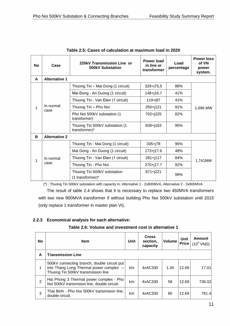
Table 2.5: Cases of calculation at maximum load in 2020
No Case 220kV Transmission Line or
500kV Substation
Power load in line or
transformer
Load percentage
Power loss of VN power
system.
A Alternative 1
1 In normal case
Thuong Tin – Mai Dong (1 circuit) 329+j75,5 88%
1,696 MW
Mai Đong - An Duong (1 circuit) 148+j16,7 41%
Thuong Tin - Van Đien (1 circuit) 119+j87 41%
Thuong Tin – Pho Noi 250+j121 91%
Pho Noi 500kV substation (1 transformer)
702+j225 82%
Thuong Tin 500kV substation (1 transformer)*
839+j163 95%
B Alternative 2
1 In normal case
Thuong Tin - Mai Dong (1 circuit) 335+j78 95%
1,741MW
Mai Dong - An Duong (1 circuit) 173+j17.6 48%
Thuong Tin - Van Đien (1 circuit) 281+j117 84%
Thuong Tin - Pho Noi 270+j17.7 92%
Thuong Tin 500kV substation
(1 transformer)*
871+j221 99%
(*) : Thuong Tin 500kV substation with capacity in: Alternative 1 - 2x900MVA, Alternative 2 - 3x900MVA
The result of table 2.4 shows that it is necessary to replace two 450MVA transformers
with two new 900MVA transformer if without building Pho Noi 500kV substation until 2015
(only replace 1 transformer in master plan VI).
2.2.3 Economical analysis for each alternative:
Table 2.6: Volume and investment cost in alternative 1
No Item Unit Cross
section, capacity
Volume Unit Price
Amount
(109 VND)
A Transmission Line
1 500kV connecting branch, double circuit put into Thang Long Thermal power complex – Thuong Tin 500kV transmission line
km 4xAC330 1.34 12.69 17.01
2 Hai Phong 3 Thermal power complex - Pho Noi 500kV transmision line, double circuit.
km 4xAC330
58 12.69 736.02
3 Thai Binh - Pho Noi 500kV transmision line, double circuit.
km 4xAC330
60 12.69 761.4

Pho Noi 500kV Substation & Connecting Branches Feasibility Study Summary Report
12
4 Dong Anh - Pho Noi 500kV transmision line, double circuit.
km 4xAC330
35 12.69 444.15
5 Pho Noi - Gia Loc 220kV transmission line, doulbe circuit.
km AC500 18 6.5 117
6 Pho Noi - Yen My 220kV transmission line, doulbe circuit.
km AC500 10 6.5 65
B Substation
1 Pho Noi 500kV substation (including 500kV feeders và 220kV connecting branches)
s/s 2x600MVA 1 1,222.94
Total 3,363.52
Table 2.7: Volume and investment cost in alternative 2
No Item Unit Cross
section, Capacity
Volume Unit Price
Amount
(109 VND)
A Transmission Line
1 Hai Phong 3 Thermal power complex - Thuong Tin 500kV transmission line, doulbe circuit.
km 4xAC330
80 12.69 1,015.2
2 Thai Binh - Thuong Tin 500kV transmission line, doulbe circuit.
km 4xAC330
72 12.69 913.68
3 Dong Anh - Thuong Tin 500kV transmission line, doulbe circuit.
km 4xAC330
45 12.69 571.05
4 Pho Noi - Gia Loc 220kV transmission line, doulbe circuit.
km AC500 22 6.5 143
5 Pho Noi - Yen My 220kV transmission line, doulbe circuit.
km AC500 12 6.5 78
B Substation and feeder
1 Enhance power capacity of 500kV Thuong Tin substation
s/s 2x900MVA*
1 282
2 500kV feeders feeder 7 62.5 437.5
Total 3,440.43
(*): Replace two 450 MVA transformers with two new 900MVA transformers at Thuong Tin 500kV substation in
2015.`
By compairing the volume and investment cost of alternative 1 with that of alternative 2,
the total investment cost of alternative 1 is 76.91 billion VND lower.
2.2.4 Select reasonable alternative:
Through above calculation, the technical specification of alternative 1 is better and the
total investment cost is lower than that of alternative 2. Alternative 1 takes advantages of the
implementation of connecting 500kV transmission lines to big Thermal power complexes, of
extensible ability for simple substation, of safe operation and long time planning until 2020.

Pho Noi 500kV Substation & Connecting Branches Feasibility Study Summary Report
13
With above analysis, plan 1 should be recommended for connecting Hai Phong 3
Thermal power complex to the National Power system and it is necessary to build Pho
Noi 500kV substaion in this alternative. Besides the convenient connection, the other
missions of Pho Noi 500kV substation is to distribute power and supply power for load
demand in the area.
Pho Noi 500kV substation can be completely built before Hai Phong 3 Thermal power
complex shall be put into operation. To select the suitable time of building Pho Noi 500kV
substation, it is necessary to analyse, calculate load flow in 2012 and 2013.
- In 2012: Without Pho Noi 500kV substation, the voltage quality at 220kV busbar of
substation in the North area shall be in range ±5%Urated and the lowest one is of An
Duong 220kV substation (216.9kV), Bac Ninh 2 (217.9kV); the total power loss of
North power system is 126MW (500kV and 220kV power network).
- In 2013: Without Pho Noi 500kV substation, the voltage quality at 220kV busbar of the
subsations connected after 500kV Thuong Tin such as Pho Noi (205.8kV), Hai Duong
(205.1kV), Bac Ninh 2 (205kV) will exceed -5%Urated, the total power loss of the North
electricity system is 256MW (500kV and 220kV power network). If install two 600MVA
transformers at Pho Noi 500kV substation, the voltage quality becomes better
(219.4kV, the lowest voltage is of 220kV bus bar at Hai Duong 220kV substation) and
the total power loss of the North power system is 233MW (23MW lower)
- With above mentioned analysis, Pho Noi 500kV substation should be equipped with
two new 600MVA transformers and be put into operation in 2013. As above mentioned
selection, the project shall be considered connecting Pho Noi 500kV substation to the
National Power System in 2 following cases.
Case 1: Pho Noi 500kV substation shall be connected to one existing circuit of Quang
Ninh – Thuong Tin 500kV transmission line (or Thang Long Thermal Power Complex –
Thuong Tin 500kV transmission line).

Pho Noi 500kV Substation & Connecting Branches Feasibility Study Summary Report
14
Pmax:
Losses: 836MW
42240MW
Heä thoáng ñieän 500kV Mieàn Baéc naêm 2015
Cheá ñoä phuï taûi cöïc ñaïi
Phöông aùn 1-Tröôøng hôïp 1
Töø Vuõng AÙng 3600+j122.9
Ñi Ñaø Naüng
Thanh Hoaù
NÑ. Nghi Sôn
Vuõng AÙng 1, 2
Haø Tónh
Huoäi QuaûngSôn La Lai Chaâu
Naâm Chieán
Hoaø Bình
Baéc Ninh
Ñoâng Anh
Hieäp Hoaø
Vieät Trì
Hoaøi Ñöùc
Nho Quan
Thöôøng Tín
Phoá Noái
NÑ.Haûi Phoøng 3
NÑ Th.Long
NÑ.MDöông
Q.Ninh
NÑ. QNinh
600+j122.92x(
2x(600+j69.4
414+j498.6
525.8+j92.8
215.7+j119.8
764.2+j128
1599.4+j293.8
248.6-j235.8
3x(250+j61.9
2x(600+j360.0
1199.4+j605
600+j17.5400+j98.82x(
2x(400+j98.8
957.9+j447.8
1168+j520.2
-237.2+j332.1
286.2-j376.8
726.4+j446
147.6+j46.5
789.9+j234.1
-68.4+j140.0
747.4-j13.5
430.4-j0.5
729.7+j135.5
713.6+j459.6
-271.9+j74.3
681.9+j529.5
1405.4+j435
943.2+j618.2
905.4+j201.8
49-j137.7
-123.8+j69.2
246+j72.0
948.4+j501.2
343.4+j320.2
2243.6+j758.6
300-j240.2
140+j113.810x(
719.8-j224.2 8x(90+j10.9
223.4kV
-63.5-j20.2
235.2kV
517.3kV
258.9-j109.7
518.2kV
231.2kV
1633-j140.2
-92.6+j478
230.0kV
-1105.8+j111.4
522.0kV 920.2+j170.9
394.4+j413.4507.5kV
230.6kV
343.2-j94.6
511.5kV
520.0kV228.0kV
506.6kV
511.3kV
-515.3+j173.4
522.6kV
524.9kV
225.6kV
222.5kV
504.5kV
Pitoong
225.5kV
521.8kV
497.4kV490.8kV
218.0kV
224.6kV
217.6kV
508.5kV
221.3kV
497.0kV
231.3kV
493.2kV
515.1kV
224.8kV
518.0kV
Figure 2.9: Load flow of 500kV power network in the North area in 2015 - Case 1
488.4-j452.4
Ñi Ñaø Naüng
426-j133.2
1669.4+j535.6
514.6kV
TÑ Tích Naêng
Heä thoáng ñieän 500kV Mieàn Baéc naêm 2020
Cheá ñoä phuï taûi cöïc ñaïi
Phöông aùn 1-Tröôøng hôïp 1
627.2+j57.4
217.7kV
501.1kV626.5+j113.3
Vónh Yeân
4x(300+j155.3
506.3-j44.9
1120.5-j57.2
Tr.Quoác
1500+j300
224.4kV
492.0kV
645.2+j321.2
643.9+j396.6
Thaùi Nguyeân
806.6+j278.8
220.4kV
500.3kV
491.9+j11.6
Baéc Giang
227.1kV
424.9+j508.8
494.9kV
78.2-j454.4
Thaùi Bình
Ñi Vuõng AÙn 3
Thanh Hoaù
NÑ. Nghi Sôn
Vuõng AÙng 1, 2
Haø Tónh
Sôn La
Lai Chaâu
Naâm Chieán
Hoaø Bình
Baéc Ninh
Ñoâng Anh
Hieäp Hoaø
Vieät Trì
Hoaøi Ñöùc
Nho Quan
Thöôøng Tín
Phoá Noái
NÑ.Haûi Phoøng 3
NÑ Th.Long
NÑ.MDöông
Q.Ninh
NÑ. QNinh
500-j79.72x(
2x(600+j86.6
316.9+j265.2
1275.6-j102
-39.1+j85.3
1367.6+j436.6
2199.8+j277.8
248.2-j304
3x(300+j112.7
2x(600+j360.0
1199.8+j622
600+j349.4
600+j104.72x(2x(500+j99.1
941.5+j179.9
1727+j342.6
487.3+j74.1
629.2+j300.8
904+j477
405.9-j19.6
617.2+j124.8
1004.9+j359.6
502.5+j95.6
1937.4+j386.8805.4+j328.2
343+j144.0
1280.8+j337.41547.2+j193.8618.6+j247.3
1229.8+j614.8
1125.9+j395.5
547-j27.6
-33.5+j7.0
1257.6+j105.2
426.2-j25.6
1745.4-j21.6
220+j65.010x(
1198.8-j460 5x(240-j80
224.2kV
182.1-j136.2
234.3kV
509.4kV
354.4+j548.8514.7kV
231.7kV
1574+j77.8
1418+j373.6
230.8kV
748.7-j144.7
511.2kV 779.1+j139.9
925.4+j433.2
498.5kV
231.4kV
602.2+j16.6
70587MW
1697MWLosses:
Pmax:
515.8kV
513.6kV219.1kV
498.9kV
500.6kV
511.6kV
505.3kV219.6kV
230.3kV
498.4kV
Pitoong
228.8kV
520.9kV
497.2kV
502.3kV
213.8kV
217.0kV
215.6kV
501.3kV
220.1kV
495.6kV
223.2kV
497.1kV 517.2kV
222.1kV
520.3kV
Figure 2.10: Load flow of 500kV power network in the North area in 2020 – Case 1

Pho Noi 500kV Substation & Connecting Branches Feasibility Study Summary Report
15
Case 2: Pho Noi 500kV substation shall be connected to 2 existing circuits of Quang
Ninh – Thuong Tin 500kV transmission line (the result of calculation is shown in figure
2.5 and 2.7)
In case 1, because Pho Noi 500kV substation was directly powered by Hai Phong 3 and
Thang Long Thermal Power Complex, voltage quality and operation are ensured in case of
normal operation as well as fault. Otherwise, because Pho Noi 500kV substation shall be
equipped with two 600MVA transformers, the majority of power thermal power complexes
shall be transmitted to transformers and reduce power transmission capacity on Pho Noi -
Thuong Tin 500kV transmission line as well as Quang Ninh –Thuong Tin 500kV transmission
line. Therefore, if one of the transmission lines may disconnect with Pho Noi 500kV
substation, the rest transmission lines can ensure power transmission in limit. Power loss of
entire system in case 1 is more than of in case 2 but this amount is small (0.5MW in 2015
and 1MW in 2020).
In terms of economic, total investment cost in building substation in case 1 is smaller
than in case 2. Therefore, the quantity of 500kV transmission lines connected to Pho Noi
500KV substation as well as compensating equipments in case 1 is less than in case 2.
Based on technical specification and economic factor, alternative 1 should be delected
and case 1 is recommended for plan connecting 500KV Pho Noi substation to the system.
This alternative shall be:
- Invest in building Pho Noi 500kV substation, install two 600MVA transformers and put
into operation in 2013.
- Connect Pho Noi 500kV substation to one existing circuit of Thang Long- Thuong Tin
500kV transmission line.
- To facilitate for connecting Bac Ninh 2 220kV substation into the system (in 2012), the
220kV distribution system of 500kV Pho Noi substation should be constructed in
advance.

Pho Noi 500kV Substation & Connecting Branches Feasibility Study Summary Report
16
CHAPTER 3 : SELECTING SUBSTATION CONTRUCTION LOCATION
3.1. LOCATION ALTERNATIVES
Alternative 1 : 500/220kV Pho Noi substation is located on the paddy field area belongs
to Dong Chung and Sam Khuc Hamlet, Viet Hung Commune, Van Lam District, Hung Yen
Province.
Alternative 2 : 500/220kV Pho Noi substation is located on the paddy field area belongs
to Nhuan Trach Hamlet, Duong Quang Commune, My Hao District, Hung Yen Province.
Via analysis on technical and economic indicators of two alternatives, the alternative 1 is
proposed to be selected for construction of 500/220kV Pho Noi substation. The alternative 1
is agreed by Hung Yen Provincial People’s Committee.
3.2. DESCRIPTION ON PROJECT CONSTRUCTION SITE
3.2.1. Geographical location
The 500/220kV Pho Noi substation is located on the paddy field area belongs to Dong
Chung and Sam Khuc Hamlet, Viet Hung Commune, Van Lam District, Hung Yen Province,
with geographical location as follows:
- North : boundary with the paddy field belongs to Sam Khuc Hamlet.
- South : boundary with the paddy field belongs to Dong Chung Hamlet.
- East : boundary with Bac Ninh Province.
- West : boundary with the paddy field belongs to Dong Chung Hamlet.
3.2.2. Topography
The topography in the location of substation contruction is even.

Pho Noi 500kV Substation & Connecting Branches Feasibility Study Summary Report
17
CHAPTER 4 : MAIN TECHNOLOGICAL SOLUTIONS
4.1. VOLTAGE LEVEL
Voltage level: 500kV, 220kV, 110kV and 35kV.
4.2. SUBSTATION CAPACITY
Capacity: install 02 transformers 500/220/35kV - 600MVA and 01 transformer
220/110/22kV – 125MVA.
4.3. SINGLE LINE CONNECTION DIAGRAM
- At 500kV side: using the single line connection diagram “3/2”, including: 02
transformer bays, 3 transmission lines bays and 7 spare bays.
- At 220kV side: using the single line connection diagram “Two busbar systems with
coupling breaker”, including: 03 transformer bays, 01 coupling breaker bay, 6 transmission
lines bays and 7 spare bays.
- At 110kV side: using the connection diagram “Two busbar systems with coupling
breaker”, including 01 transformer bay and 10 spare bays.
- At 35&22kV side: Design in accordance with transformer block diagram
4.4. SOLUTIONS APPLIED FOR CONTROL, PROTECTION SYSTEM
4.4.1. Control system
Using computerized control system for the substation.
The computerized control mode shall have structure of 4 levels:
- Level 1 : Controlling and monitoring from load dispatch center.
- Level 2 : Controlling from control room of substation.
- Level 3 : Controlling from control-protection cubicles of incoming bays.
- Level 4 : Controlling at equipment.
4.4.2. Protection system
The protection system for controlling elements inside substation shall be complied with
regulation specified by Vietnam Electricity. The main relays of protection system shall be of
digital relays with micro processors have interface with computerized control system and
SCADA system.
4.5. AUXILIARY POWER SUPPLY
4.5.1. AC auxiliary power
AC auxiliary power shall be supplied from 02 auxiliary transformers 35/0.4kV – 560kVA,
receive power from equipotential winding of 02 transformers 500/220/35kV.
4.5.2. DC auxiliary power
DC auxiliary power shall be supplied from 02 Nikel-Cadimi (NiCd) battery system with
capacity of 300Ah, voltage level 220VDC. The battery system shall operate under regime of

Pho Noi 500kV Substation & Connecting Branches Feasibility Study Summary Report
18
regular recharge and surcharge via 02 rectifiers with input voltage of 380VAC, output voltage
of 220VDC.
4.6. EARTHING, GROUNDING SYSTEMS
The rod-wire combination earthing system is used within substation range. Using
galvanized steel earthing rod with diameter Φ22, 5m length. The main earthing wire
and radial earthing wires shall be of galvanized steel wires with diameter Φ14, electric
welding shall be applied for connection between earthing rods and bars, earthing bars
and bars. The resistivity value of earthing system shall be in accordance with current
prevailed norms.
Earthing for equipment, equipment supports shall be of M120 copper wires, earthing
wires and earthing grid shall be connected by cad-welding.
The substation is protected from direct lightning striking by lightning rods installed on
independent lighting poles-earthing, wires shall be installed on gantry towers of
500kV, 220kV, 110kV switcgear.
Protection of over atmospheric voltage transmitted from the transmission lines to
substation and local over voltage by surge arresters.
4.7. LIGHTING SYSTEM
- The neon lamps 40W shall be used for control house lighting, incandescent lamps
75W shall be used for emergency lighting.
- The 400W beacon lights installed on lighting poles – independent lightning protection
poles shall be used for outdoor lighting.
- The 70W bulb lamps installed on 3.4m height poles shall be used for lighting
substation surrounding area.
4.8. COMPENSATING SOLUTION
At 500kV Pho Noi substation: install 02 shunt reactors 500kV - 65MVAr (shall be moved from
500kV Thuong Tin and Quang Ninh substation).
4.9. SELECTING OF MAIN ELECTRICAL EQUIPMENT
The main electrical equipment shall be selected with basic technical parameters as follows:
1/ Electrical equipment 500kV, outdoor installation:
- Rated voltage : 550kV
- Rated current : 2000A
- Rated short circuit current withstands : 50kA/3sec
- Testing voltage at power frequency 50Hz, 1min : 680kV
- Impulse withstand testing voltage 1.2/50 s : 1550kV
- Creepage distance : 25mm/kV
- Auxiliary power : 380/220VAC, 220VDC
2/ Electrical equipment 220kV, outdoor installation:

Pho Noi 500kV Substation & Connecting Branches Feasibility Study Summary Report
19
- Rated voltage : 245kV
- Rated current : 2000A (3150A)
- Rated short circuit current withstands : 50kA/3sec
- Testing voltage at power frequency 50Hz, 1min : 460kV
- Impulse withstand testing voltage 1.2/50 s : 1050kV
- Creepage distance : 25mm/kV
- Auxiliary power : 380/220VAC, 220VDC
3/ Electrical equipment 35kV, outdoor installation:
- Rated voltage : 38.5kV
- Rated current : 800A
- Rated short circuit withstand capacity : 40kA/1sec
- Testing voltage at power frequency 50Hz, 1min : 70kV
- Impulse withstand testing voltage 1.2/50 s : 170kV
- Creepage distance : 25mm/kV
- Auxiliary power : 380/220VAC, 220VDC

Pho Noi 500kV Substation & Connecting Branches Feasibility Study Summary Report
20
CHAPTER 5 : MAIN SOLUTIONS APPLIED FOR CIVIL CONSTRUCTION PART
5.1. GENERAL PLAN LAYOUT AND FOUNDATION GRADING
5.1.1. General plan layout
Land acquisition area for structures within substation general plan layout:
- Acquistion land area for substation (1) : 124,730m2
- Acquistion land area for access road to substation (2) : 55,030m2
- Acquistion land area for operation shifting house (3) : 2,350m2
- Total acquisition land area for substation [(1)+(2)+(3)] : 182,110m2
5.1.2. Foundation grading
Foundation grading: The substation construction location is located on the paddy field
and crops planting areas, with inundation in flood and rainy season in accordance with flood
level +3.35m (with frequence 2%). So, the substation foundation grading shall be done
based on filling soil.
+ Total overburden removal quantity with 0.15m thickness : 26,595 m3
+ Total soils excavation quantity : 13,254 m3
+ Total soils embankment quantity : 288,206 m3
+ Boulder stones masonry quantity : 9,643 m3
5.1.3. Road system
The roads inside substation shall have structure of asphaltic concrete in 4m and 6m
width.
The roads outside substation shall have structure of asphaltic concrete in 7,5m width.
5.2. SOLUTIONS APPLIED FOR OUTDOOR STRUCTURES
5.2.1. Towers, steel arms and equipment supports:
All of towers, steel arms shall be manufactured with figural galvanized steel lonked by
bolts, hollow pyramid structure.
The equipment supports shall be manufactured with galvanized I shape steel,
fabricated and manuafactured at the factory.
5.2.2. Solutions applied for tower foundation, equipment support foundation,
transformers foundation:
The foundation of gantry towers, busbar towers shall be of reinforced concrete, cast
in-place reinforced concrete single footing structure.
The equipment support foundation shall be of reinforced concrete, cast in-place
independent reinforced concrete single footing structure.
The power transformer foundation shall be of cast in-place reinforced concrete, raft
foundation, upper part having points for jacking and positioning transformers.
5.2.3. Solutions applied for cable trenches
The cable trenches shall be of cast in-place reinforced concrete, underground

Pho Noi 500kV Substation & Connecting Branches Feasibility Study Summary Report
21
structure, with bottom slope to drain water to water drainage pipes, galvanized steel
cable hanging frames shall be arranged inside cable trenches.
The cable trenches cover slabs shall be of pre-cast reinforced concrete.
5.3. SOLUTIONS APPLIED FOR STRUCTURE OF CONTROL HOUSE, OPERATION
SHIFT WORKING HOUSE
5.3.1. Solutions applied for control house
Two storeys house, plan area (18x27)m, height to ceiling 4.55m.
Principle force bearing structure shall be of reinforced concrete frame cast in one
block, brick masonry walls, reinforced concrete tower foundation, masonry walls
hewn stone founation.
The reinforced concrete roof with slope to drain water to both sides, heat proof and
anti-leakage corrugated steel sheets shall be covered on top.
5.3.2. Solutions applied for operation shift working house
Two houses of one storey, plan area (9.5 x 18)m2, including 05 rooms.
Force bearing structure shall be of reinforced concrete frame, masonry walls hewn
stone foundation, masonry walls, ceramic bricks floor, heat proof and anti-leakage
color steel sheets shall be covered on top.
5.4. SOLUTIONS APPLIED FOR WATER SUPPLY AND DRAINAGE, FIRE AND
EXPLOSION PREVENTION AND FIGHTING
5.4.1. Water supply and drainage system
The water source for daily life activities shall be supplied from 02 bored wells 70m
depth.
The water source for fire fighting shall be supplied from 02 bored wells 70m depth.
The rain water shall be drained following to the slope direction of substation base,
partial rain water shall be drained directly through the water draiange pipes at bottom
of substation surrounding walls, remaining part of rain water shall be drained following
to the slope of road pavement inside the substation to the catch pits arranged at
edges of road pavement.
The water in cable trenches shall be drained along the cable trenches to the water
collecting pipes, then drained to the nearest catch pits.
5.4.2. Fire and explosion prevention and fighting system
Fire fighting with water using solution: Two water tanks shall be arranged inside the
substation for supplying water for fire fighting system, with capacity of each water tank
of 130m3. The water tank structure shall be of reinforced concrete M200, self-
overflowed surface structure.
Fire fighting with sand using solution: The sand containers shall be of reinforced
concrete with diameter 1m.

Pho Noi 500kV Substation & Connecting Branches Feasibility Study Summary Report
22
Bored well: The bored wells shall have 70m depth, arranged inside substation. The
regular water exploiting discharge shall be 1.875 liters/s, with sufficient volume for
supplying water for daily life activities and fire fighting.
Fire and explosion prevention and fighting system: The automatic fire fighting system
shall be equipped. In addition, the fire fighting inside substation shall also be
equipped with the fire fighting drums such as foam, CO2 and other manual tools
including ladders, buckets, shovels...

Pho Noi 500kV Substation & Connecting Branches Feasibility Study Summary Report
23
CHAPTER 6 : SOLUTIONS APPLIED FOR CONNECTING BRANCHES
6.1. CONNECTING BRANCHES 500kV
The 500kV connecting branches connected to Pho Noi 500kV substation shall cross
through territory of Van Lam district, Hung Yen Province.
Voltage level: 500kV.
Number of circuits: 2
Starting point: shall be connected to the tower span 273 - 274 of existing Quang Ninh
– Thuong Tin 500kV transmission lines.
Ending point: At gantry tower 500kV of Pho Noi 500kV substation.
Length: 1,230 m
Conductors: 4xACSR-330/42.
Grounding wires: Suspension of 01 optical composite grounding wire OPGW-80 and
01 grounding wire PHLOX-116.
Insulators: glass or ceramic insulator or equivalent technical characteristics insulators
in accordance with IEC standards.
Tower: Using free standing figural galvainzed steel, linked by bolts.
Foundation: Using cast in-place reinforced concrete foundation.
Earthing: Using radial type earthing system. The resistivity value of earthing system
shall be in accordance with current prevailed norms.
Vibration damper: The vibration dampers shall be used for conductor, grounding wires
and optical cables.
6.2. CONNECTING BRANCHES 220kV
6.2.1 Connecting branches No.1:
The 220kV connecting branches connected to Pho Noi 500kV substation shall cross
through territory of Van Lam district, Hung Yen Province; Thuan Thanh district, Bac Ninh
Province; Cam Giang district, Hai Duong Province;.
Voltage level: 220kV.
Number of circuits: 4 (install 02 circuits in this stage)
Starting point: shall be connected to the tower span 68 - 69 of existing Pha Lai – Pho
Noi – Thuong Tin 220kV transmission lines.
Ending point: At gantry tower 220kV of Pho Noi 500kV substation.
Length: 5,107 m
Conductors: ACSR-400/51.
Grounding wires: Suspension of 01 optical composite grounding wire OPGW-70 and
02 grounding wire GSW-70.
Insulators: glass or ceramic insulator or equivalent technical characteristics insulators
in accordance with IEC standards.
Tower: Using free standing figural galvainzed steel, linked by bolts.
Foundation: Using cast in-place reinforced concrete foundation.
Earthing: Using radial type earthing system. The resistivity value of earthing system
shall be in accordance with current prevailed norms.

Pho Noi 500kV Substation & Connecting Branches Feasibility Study Summary Report
24
Vibration damper: The vibration dampers shall be used for conductor, grounding wires
and optical cables.
6.2.2 Connecting branches No.2:
The 220kV connecting branches connected to Pho Noi 500kV substation shall cross
through territory of Ngoc Lien Commune, Cam Giang District, Hai Duong Province;
Luong Tai and Viet Hung Commune, Van Lam District, Hung Yen Province.
Voltage level: 220kV.
Number of circuits: 4 (install 02 circuits in this stage)
Starting point: shall be connected to the tower span 73 - 74 of existing Pha Lai – Pho
Noi – Thuong Tin 220kV transmission lines.
Ending point: At gantry tower 220kV of Pho Noi 500kV substation.
Length: 4,578 m
Conductors: ACSR-400/51.
Grounding wires: Suspension of 01 optical composite grounding wire OPGW-70 and
02 grounding wire GSW-70.
Insulators: glass or ceramic insulator or equivalent technical characteristics insulators
in accordance with IEC standards.
Tower: Using free standing figural galvainzed steel, linked by bolts.
Foundation: Using cast in-place reinforced concrete foundation.
Earthing: Using radial type earthing system. The resistivity value of earthing system
shall be in accordance with current prevailed norms.
Vibration damper: The vibration dampers shall be used for conductor, grounding wires
and optical cables.

Pho Noi 500kV Substation & Connecting Branches Feasibility Study Summary Report
25
CHAPTER 7 : SOLUTIONS APPLIED FOR SUBSTATION SERVICE POWER SUPPLY
TRANSMISSION LINE
Voltage level: 22kV
Number of circuits: 1
Starting point : Tower No. 136 of the 22kV transmission line supplying power for Nhan
Vinh 22kV substation.
Ending point : Substation service power supply 22 (35)/0.4kV-560kVA substation.
Construction local: Dai Dong and Viet Hung Commune, Van Lam District, Hung Yen
Province.
Length : 2,423m.
Conductor : ACSR-70/11.
Insulators: glass or ceramic insulator or equivalent technical characteristics insulators
in accordance with IEC standards.
Tower: Centrifugal spun reinforced concrete column, 10.5m height.
Tower foundation: Cast in-place reinforced concrete mass foundation.
Arms, fastening belts: using figural hot dip galvanized steel .
Other technical solutions: Earthing, prohibition boards, signboards on the
transmission lines shall be arranged according to Electrical equipment Code No. 11
Branch Standard TCN 19-2006.
Pho Noi 500kV Substation & Connecting Branches Feasibility Study Summary Report
26
CHAPTER 8 : SOLUTIONS APPLIED FOR TELECOMMUNICATION
8.1. SOLUTION APPLIED FOR PLC TELECOMMUNICATION
8.1.1 At 500kV side:
Currently, phase-phase (A-B) Power Line Carrier telecommunication system is operating on
Quang Ninh – Thuong Tin 500kV transmission line. When Pho Noi 500kV substation shall be
put into operation, it shall be connected to 500kV Quang Ninh – Thuong Tin transmission line.
This project shall consider transferring PLC equipments (line trap, power line carrier, device
coupling, teleprotection…) from Thuong Tin to Pho Noi in order to re-establish PLC
telecommunication system on Quang Ninh – Pho Noi 500kV transmission line and to equip new
PLC equipments which shall be synchronous with equipments of Thuong Tin – Pho Noi for
establishing PLC telecommunication system on Thuong Tin – Pho Noi 220kV transmission line
(protecting for Thuong Tin – Pho Noi 500kV transmission line).
8.1.2 At 220kV side:
Currently, phase-ground (phase B) PLC telecomunication system is operating on Pha Lai
Thermal power complex – Thuong Tin 220kV transmission line. The PLC telecommunication
system of Pha Lai Thermal power complex – Pho Noi has been taken back for other projects.
The electricity solution of project: connecting to Pha Lai Thermal power complex – Thuong
Tin and Pha Lai Thermal power complex – Pho Noi 220kV transmission line.
This project shall consider transferring PLC equipments (line trap, device coupling, power
line carrier …) from Thuong Tin 500kV substation to Pho Noi 500kV substation in order to re-
establish PLC telecommunication system on Pha Lai Thermal power complex – Pho Noi 220kV
transmission line (1 circuit). The PLC telecommunication system on 220kV transmission line
connecting Pho Noi 220kV substation to Pho Noi 500kV substation shall be formed (and
equipped with new ground wire) for optical transmission application.
Invest new PLC telecomunication system on Thuong Tin - Pho Noi 220KV transmission line
(or consider transferring equipments of internal NPT) to supply intertripping telecommunication
channel for back-up protection of Thuong Tin – Pho Noi 500kV transmission line (2 circuits)
At that time, intertripping transmission for protection of Thuong Tin – Pho Noi 220kV
transmission line shall use digital channel of optical telecommunication line on 500kV
transmission line, intertripping transmission for protection of 220kV transmission line connecting
Pho Noi 220kV substation to 500kV Pho Noi substation shall use digital channel of optical
communication line on 220kV transmission line.
Intertripping transmission for protection of Pha Lai – Pho Noi 220kV transmission line (2
circuits) shall use its circuit 1 for PLC telecommunication transmission.
8.2. SOLUTION APPLIED FOR OPTICAL TELECOMMUNICATION
The OPGW-24SM optical telecommunication system is operating with the transmission
speed of 2,5Gbit/s on Quang Ninh – Thuong Tin 500kV transmission line. This project will invest
1 equipment package including STM16, PCM-30, PABX for Pho Noi 500kV substation to
Pho Noi 500kV Substation & Connecting Branches Feasibility Study Summary Report
27
drop/insert and transmit telecommunication signal to substation.
It is expected that when Pho Noi 500kV substation shall be put into operation, it shall be
connected to one 500kV feeder of Hiep Hoa 500kV substation and two 220kV feeders of Bac
Ninh 2 220kV substation. Therefore, STM-16 equipment shall be eqipped with spare interface
transmission cards to transmit telecommunication signal to Hiep Hoa 500kV substation and Bac
Ninh 2 220kV substation.
Establish ring telecommunication system: << Thuong Tin – Pho Noi – Quang Ninh –
Thuong Tin >>. When Hiep Hoa 500kV substation and Bac Ninh 2 220kV substation shall be
connected to Pho Noi 500kV substation, this will form a ring << Pho Noi – Hiep Hoa – Bac Ninh
2 - Pho Noi >>.
For 220kV transmission line connecting Pho Noi 220kV substaion to Pho Noi 500kV
substation: invest optical cable (and equip with new ground wire) and equip it with terminal
equipment at Pho Noi 220kV substation which shall be synchronous with that of Pho Noi 500kV
substation to establish telecommunication channels for application (intertripping, transferring
equipments from PLC channels to optical telecommunication channels for SCADA and hot-
line…)
The exchange capacity at Pho Noi 500kV substation shall have more than 32
telecommunication channels which are served for telecommunication demand and electricity
system balance of substation. It shall be connected 2MBps trunk to Flexicom-6000 exchange at
VT1 (18 Tran Nguyen Han) and shall be prepared with spare trunks for connecting to
exchanges at Hiep Hoa 500kV substation and Bac Ninh 2 220kV substation.
Establish voice channel and data channel to transmit SCADA signal and hot-line to A1 and
A0.
This project has been a change of PLC transmission to optical telecommunication
transmission at Pho Noi 220kV substation. Therefore, it is necessary to modify its connection
for re-establishing the current PLC channel to optical telecommunication channel in this
investment.

Power Transmission Investment Program (RRP VIE 42039)
1
Feasibility Study Project Number: 42039-034 November 2011
Multitranche Financing Facility Socialist Republic of Viet Nam: Power Transmission Investment Program
Summary Report
200 kV Phu My 2 Industrial Zone Substation

200 kV Phu My 2 Industrial Zone Substation Feasibilty Study Summary Report
2
Table of Contents
1. Necessity
1.1 Project necessity .................................................................................................... 4
1.2 Project objectives ................................................................................................... 5
1.3 Geographical features ............................................................................................ 5
1.4 Economy, society of project situation ...................................................................... 6
1.5 Existing and future electrical source layout ............................................................. 6
2. Location and Project size ............................................................................................... 8
2.1 Geography ............................................................................................................ 8
2.2 Scope of Project ..................................................................................................... 8
Substation ...................................................................................................................... 8
Communication and SCADA system .............................................................................. 8
Transmission line connection ......................................................................................... 8
3. Load forecast ................................................................................................................. 9
3.1 Local load situation ................................................................................................. 9
Industry and agriculture .................................................................................................. 9
Infrastructure .................................................................................................................. 9
Investment attraction project .......................................................................................... 9
Load and generation needs ............................................................................................ 9
Load forecast after 2010 .................................................................................................. 10
4. Technical solutions ....................................................................................................... 11
Choosing voltage level ..................................................................................................... 11
Choosing substation capacity, quantity of power transformer ........................................... 11
Choosing quantity of outgoing feeders at voltage levels ................................................... 11
Choosing main connection diagram ................................................................................. 11
Electrical layout regarding to future upgrading ................................................................. 12
Choosing technical solution for measuring, control and protection system. ...................... 13
Control system ............................................................................................................. 13
Measuring system ........................................................................................................ 13
Protection and automation system ............................................................................... 13
Auxiliary supply ................................................................................................................ 15
380/220 V AC system .................................................................................................. 15
DC distribution system ................................................................................................. 15
Lightning protection, earthing and illuminating system: .................................................... 15

200 kV Phu My 2 Industrial Zone Substation Feasibilty Study Summary Report
3
Lightning protection system .......................................................................................... 15
Earthing system ........................................................................................................... 15
Illuminating and security systems ................................................................................. 15
Main construction solutions .............................................................................................. 16
Main characteristics ..................................................................................................... 16
General layout .............................................................................................................. 16
Level the layout ............................................................................................................ 16
Outdoor construction solutions ......................................................................................... 16
Supporting structures ................................................................................................... 16
Foundations ................................................................................................................. 16
Cable trenches ............................................................................................................. 16
Gates and fences ......................................................................................................... 17
Interior road and access road ....................................................................................... 17
Oil sump tank ............................................................................................................... 17
Structural and architectural solutions for control building and other auxiliary houses ....... 17
Structural solution ........................................................................................................ 17
Architectural solution .................................................................................................... 17
Technical solutions for water supply, drainage and fire fighting systems .......................... 18
Water supply system .................................................................................................... 18
Drainage system .......................................................................................................... 18
Fire fighting system ...................................................................................................... 18
Ventilation of control building ........................................................................................... 19
Network connection solutions........................................................................................... 19
Substation transmission line connections ..................................................................... 19
Communication ............................................................................................................ 19
Data transmission technology solution ......................................................................... 19

200 kV Phu My 2 Industrial Zone Substation Feasibilty Study Summary Report
4
1. Necessity
1.1 Project necessity
According to “Power grid scheme development and improvement in 2006-2010 stage, regarding to 2015 of Tan Thanh district, Ba Ria-Vung Tau province”, load forecasting of zones of Tan Thanh district was listed as follows:
Table A: 110 kV substations on period before 2010
Substation Year of Operation
Power Installation
(MVA)
Load (%) Power load
(MVA)
Total (MVA)
Phu My steel Existing 100 75 75 120
60 75 45
Phu My Existing 63 75 47.25 94.5
63 75 47.25
Phu My 1 Existing 30 75 22.5 45
30 75 22.5
Thep Viet Existing 45 75 33.75 67.5
45 75 33.75
Posco 2008 150 74 111 111
Thi Vai 2008 63 50 31.5 63
63 50 31.5
Total 501
On this condition, two transformers T5 and T6 (2x250MVA) of Phu My 1 thermal plant can be suitable.
Table B: Load forecast 110 kV substations on period after 2010
Substation Year of operation
Power installation
(MVA)
Load factor
(%)
Consumed power (MVA)
Total (MVA)
Phu My steel Existing 100 80 80.0 128.0
60 80 48.0
Phu My Existing 63 80 50.4 100.8
63 80 50.4
Phu My 1 Existing 30 80 24.0 48.0
30 80 24.0
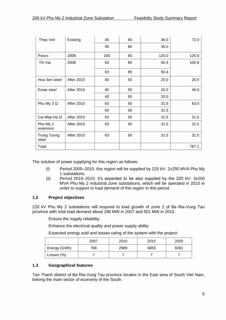
200 kV Phu My 2 Industrial Zone Substation Feasibilty Study Summary Report
5
Thep Viet Existing 45 80 36.0 72.0
45 80 36.0
Posco 2008 150 80 120.0 120.0
Thi Vai 2008 63 80 50.4 100.8
63 80 50.4
Hoa Sen steel After 2010 40 50 20.0 20.0
Essar steel After 2010 40 50 20.0 40.0
40 50 20.0
Phu My 3 IZ After 2010 63 50 31.5 63.0
63 50 31.5
Cai Mep Ha IZ After 2010 63 50 31.5 31.5
Phu My 2 extension
After 2010 63 50 31.5 31.5
Trung Tuong steel
After 2010 63 50 31.5 31.5
Total 787.1
The solution of power supplying for this region as follows:
(i) Period 2005–2010: this region will be supplied by 220 kV- 2x250 MVA Phu My 1 substations.
(ii) Period 2010–2015: it’s expected to be also supplied by the 220 kV- 3x250 MVA Phu My 2 industrial zone substations, which will be operated in 2010 in order to support to load demand of this region in this period.
1.2 Project objectives
220 kV Phu My 2 substations will respond to load growth of zone 2 of Ba Ria-Vung Tau province with total load demand about 186 MW in 2007 and 501 MW in 2010.
Ensure the supply reliability.
Enhance the electrical quality and power supply ability
Expected energy sold and losses rating of the system with the project:
2007 2010 2015 2020
Energy (GWh) 788 2989 5855 9281
Losses (%) 7 7 7 7
1.3 Geographical features
Tan Thanh district of Ba Ria-Vung Tau province locates in the East area of South Viet Nam, belong the main sector of economy of the South.

200 kV Phu My 2 Industrial Zone Substation Feasibilty Study Summary Report
6
Being contiguous to Dong Nai province in the North, to Chau Duc district in the East, to Can Gio district (Hochiminh City) in the West and Ba Ria town in the South. It’s about 65km far from Ho Chi Minh City.
Natural area: 34,152 ha.
Population: 92,923 people in 2007.
The district has 1 township and 8 communes: Phu My Township, My Xuan, Phuoc Ha, Hoi Bai, Chau Pha, Hac Dich, Toc Tien and Song Xoai commune.
1.4 Economy, society of project situation
Economic structure had rather grown quick, by 78% industry and 16% living activities agriculture in the last two year.
Industry: Industrial production has averaged value out at 38% a year.
Service: GDP of service increased by 19.24% in 2005–2006 and has averaged at 15–20% a year in a period 2006–2010.
Agricultural: Cultivated area: 53,841 ha, decrease 1.8% in the same time of the last year.
Import-export: Import-export turn-over has averaged value out at 28.9% a year.
In period of 2010 (2020), Tan Thanh district has planned to develop 07 industrial zones with total area 5,233ha such as : Phu My II; Cai Mep, Phu My II extension, Phu My III, Cai Mep Ha, Long Huong and Long Son.
1.5 Existing and future electrical source layout
In present, Ba Ria-Vung Tau power grid is mainly supplied by the 500 kV- 450 MVA Phu My substation and two 500 kV Phu My-Nha Be and Phu My- Phu Lam transmission lines and the 220 kV Phu My-Ba Ria, Phu My-Long Thanh, Phu My-Nha Be, Phu My-Cat Lai transmission lines across this province.
There are substations in this area as follows:
500 kV Phu My substation:
- Situated in Tan Thanh district, Ba Ria-Vung Tau province
- Rated voltage: 500/220 kV-450 MVA, 220/110 kV-2x250 MVA
- Supplied by the transmission lines 500 kV Phu My-Nha Be and Phu My-Phu
Lam.
- Supply mainly to 110 kV Phu My, Thep Viet, Phu My steel plant and Posco
substations.
220kV Phu My substation:
- Situated in Tan Thanh district, Ba Ria-Vung Tau province.
- Rated voltage: 220/110kV
- Capacity: 2x250MVA
- Supplied by the 500/220kV Phu My substation.
- Supply mainly to 110kV Phu My, Thep Viet, Phu My steel plant and Posco
substations.
110 kV Phu My steel plant substation:
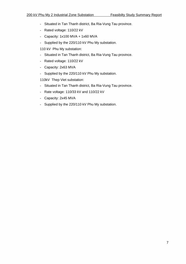
200 kV Phu My 2 Industrial Zone Substation Feasibilty Study Summary Report
7
- Situated in Tan Thanh district, Ba Ria-Vung Tau province.
- Rated voltage: 110/22 kV
- Capacity: 1x100 MVA + 1x60 MVA
- Supplied by the 220/110 kV Phu My substation.
110 kV Phu My substation:
- Situated in Tan Thanh district, Ba Ria-Vung Tau province.
- Rated voltage: 110/22 kV
- Capacity: 2x63 MVA
- Supplied by the 220/110 kV Phu My substation.
110kV Thep Viet substation:
- Situated in Tan Thanh district, Ba Ria-Vung Tau province.
- Rate voltage: 110/33 kV and 110/22 kV
- Capacity: 2x45 MVA
- Supplied by the 220/110 kV Phu My substation.
200 kV Phu My 2 Industrial Zone Substation Feasibilty Study Summary Report
8
2. Location and Project size
2.1 Geography
The 220 kV Phu My 2 industrial zone substation will be constructed in Ong Trinh ward, Tan Phuoc commune, Tan Thanh district, Ba Ria-Vung Tau province.
2.2 Scope of Project
Substation
Two power auto-transformers: 225+8x1.25%/115/23 kV– 250 MVA.
220 kV side: double busbar diagram with bus-tie.
220kV bays: two transformer bays, four O/H line outgoing bays (Phu My 1, Phu My 2 and Ba Ria 1, Ba Ria 2), one bus coupling bay.
110 kV side: double busbar diagram with bus-tie.
110 kV bays: two 250 MVA transformer bay, one bus coupling bay, eight O/H line outgoing bays (Posco 1, Posco 2, Thi Vai 1, Thi Vai 2, Phu My 1, Phu My 2, Southern Steel 1, and Southern Steel 2).
22 kV side diagram: single busbar (only supply power for 02 auxiliary transformers)
Control and protection equipment: using computerized control and modern protection systems. The control, protection cubicles are placed indoor, and communicate with computerized control system by fiber optic cables. Measuring and protection is equipped in accordance with EVN Standard and Regulations.
Communication and SCADA system
One optical communication route is established between 220kV Phu My 2 industrial zone substation and 220 kV Phu My thermal plant substation.
One public telephone subscribe of Ba Ria-Vung Tau province.
Send/Receive SCADA/EMS signals between Southern Load Dispatching Center and 220 kV Industrial zone Phu My 2 substation via the computerized system gateway connected to optical communication system of 220 kV Industrial zone Phu My 2 substation and existing optical communication system.
Transmission line connection
220 kV side
The substation is connected to the 220 kV Phu My thermal plant – Ba Ria thermal plant double circuit transmission lines.
110 kV side:
220/110 kV Phu My 2 industrial zone substation has 8 outgoing feeders, including 2 feeders supply power to the existing 110 kV Southern Steel substation, 2 feeder supply to the existing Phu My substation, 2 feeder supply to Posco substation and 2 feeder supply to Thi Vai substation.

200 kV Phu My 2 Industrial Zone Substation Feasibilty Study Summary Report
9
3. Load forecast
3.1 Local load situation
Industry and agriculture
Agriculture:
- The cultivated area is decrease because the new areas for industrial zone
increase very fast in recent year.
Industry:
- Due to geography, it can attract investment’s capital for industry such as: steel,
mechanism, textile and others. There are some industrial zones which are planed
by the local governor such as Phu My I, II; My Xuan A1, My Xuan A2, My Xuan
B1, Cai Mep, Long Son and Phu My III and so on.
- Industrial economic sector plays important roles and bases for improving other
economic sectors.
Infrastructure
Traffic:
- The local governor is constructing and upgrading traffic routes of the district very
fast.
Import-export:
- Import-export turn-over has averaged value out at 29% a year.
Investment attraction project
Domestic investment: In present, Tan Thanh district has 157 private, limited, joint-stock companies … with total charter capital is about 5.89 billion USD and total business capital has increased about 3–5 times.
Foreign investment: In present, Tan Thanh district has 75 foreign-invested projects with total invested capital more than 4.43 billion USD.
Load and generation needs
In future, Tan Thanh district will be one of the best industrial and economic centers in the East South of Viet Nam. Power demand increases continuously. Responding to this demand is an urgent task of the EVN, so constructing transmission substations and lines for this area is urgent necessity.
a. Electrical using structure: see Table 1.
According to statistical and forecasted values in 2005,2010 and 2015 period, electricity supplying for living activities was over 16.8%, this rate reduced to 15.7% in 2015. The rate of electricity for industry came the first, after living activities, always over 74% each year and has increased gradually in recent years.
b. The average rate of electricity demand growing per year:
(i) 2006–2010 periods: 25% (ii) 2015 periods: 36%

200 kV Phu My 2 Industrial Zone Substation Feasibilty Study Summary Report
10
Load forecast after 2010
The 220 kV Phu My 2 industrial zone substation is expected to supply power for 110 kV substations after 2010, as following:
Substation Year of operation
Power installation
(MVA)
Load (%) Power load (MVA)
Total (MVA)
Phu My steel Existing 100 80 80.0 128.0
60 80 48.0
Phu My Existing 63 80 50.4 100.8
63 80 50.4
Phu My 1 Existing 30 80 24.0 48.0
30 80 24.0
Thep Viet Existing 45 80 36.0 72.0
45 80 36.0
Posco 2008 150 80 120.0 120.0
Thi Vai 2008 63 80 50.40 100.8
63 80 50.40
Hoa Sen steel After 2010 40 50 20.0 20.0
Essar steel After 2010 40 50 20.0 40.0
40 50 20.0
Phu My 3 IZ After 2010 63 50 31.50 63.0
63 50 31.50
Cai Mep Ha IZ After 2010 63 50 31.50 31.5
Phu My 2 extension
After 2010 63 50 31.50 31.5
Trung Tuong steel
After 2010 63 50 31,50 31.5
Total 787.1

200 kV Phu My 2 Industrial Zone Substation Feasibilty Study Summary Report
11
4. Technical solutions
Choosing voltage level
Selected voltage levels are:
High voltage levels: 220 kV, 110 kV
Medium voltage level: 22 kV
Choosing substation capacity, quantity of power transformer
In accordance with the result of power flow, expectation of substation’s capacity is 3x250 MVA for 220/110 kV substation. In this stage will be installed the two transformers 250 MVA. In the future stage will be installed the third transformer 250 MVA.
Choosing quantity of outgoing feeders at voltage levels
According to “The master plan of electrical developing of Tan Thanh district” and local power grid, expectative outgoing feeders are listed below:
220 kV side:
- In this stage will be installed 04 outgoing feeders as follows: Phu My 1, Phu My 2
and Ba Ria 1, Ba Ria 1.
- The spare space will be planed for 02 outgoing feeders as follows: Son My 1,
Son My 2 and two spare feeders.
110 kV side:
- In this stage will be installed 08 outgoing feeders as follows: Posco 1, Posco 2,
Thi Vai 1, Thi Vai 2, Phu My 1, Phu My 2, and Southern steel 1, Southern steel 2.
- The spare space will be planed for 08 future outgoing feeders as follows: 02 bays
for Cai Mep industrial zone, 02 bays for Phu My 3 industrial zone, 02 bays for
Phu My 2 industrial zone extension, and two spare feeders for capacitors.
22 kV side:
- Only supply for auxiliary transformer.
Choosing main connection diagram
The basic requirements of electrical connection diagram are security, confidence, simple structure, flexible operation, economy and human safety.
220 kV side
- Use double busbar scheme. In this stage, it is installed with following bays:
- Two bays for O/H line feeder to Phu My substation.
- Two bays for O/H line feeder to Ba Ria substation.
- Two bays for 1T and 2T transformers (250MVA)

200 kV Phu My 2 Industrial Zone Substation Feasibilty Study Summary Report
12
- One bay for bus coupler
In future, the following bays will be installed:
- One bay for the transformer 3T.
- Two bays for O/H line feeder to Son My thermal plant.
- Two bays for spare
- The 220 kV busbar: aluminium Ø160/148mm.
110 kV side
Use double busbar scheme. In this stage, it is installed with following bays:
- Two bays for 1T and 2T transformers (250 MVA)
- One bay for bus coupler
- Two bays for O/H line feeder to 110 kV Posco substation.
- Two bays for O/H line feeder to 110 kV Thi Vai substation.
- Two bays for O/H line feeder to 110 kV Southern Steel substation.
- Two bays for O/H line feeder to 110 kV Phu My 1 substation.
In future, the following bays will be installed:
- One bay for 3T transformer (250 MVA).
- Two bays for O/H line feeder to 110 kV Cai Mep industrial zone substation.
- Two bays for O/H line feeder to 110 kV Phu My 3 industrial zone substation.
- Two bays for O/H line feeder to 110 kV Phu My 2 industrial zone extension
substation.
- Two spare bays for 110 kV capacitor banks.
- The 110 kV busbar: aluminium Ø160/148mm.
22 kV side
Use single busbar scheme, outdoor equipment. Only supply for auxiliary transformer with following bays:
- Two set of 22 kV incoming circuit breakers
- Six set of 22 kV voltage transformers
- Six set of 22 kV current transformers
- Two set of three phases disconnectors
- Six set of 22kV lightning arresters
Electrical layout regarding to future upgrading
220 kV Phu My 2 industrial zone substation’s layout is designed for installation for 3 auto-power transformers 250 MVA.

200 kV Phu My 2 Industrial Zone Substation Feasibilty Study Summary Report
13
Choosing technical solution for measuring, control and protection system.
Control system
Control system for 220 kV, 110 kV, 22 kV feeders will be equipped with several levels as follows:
- Bay levels: at equipment for maintenance only and “Bay controller” placed at
control and protection cubicles, for emergency control.
- Substation level: by computerized control system in the control room.
- System level: from SLDC by SCADA system.
Computer control system must use the open system, using LAN net, Ethernet with the new communication standard: IEC 61850.
Measuring system
System state parameter will be accessed by bay’s measuring system, computer system and SCADA.
220 kV side of main transformer: equip one multi-functional meter for A, V, W, VAr, Cos , Wh, VArh, and communication port for central control system and SCADA/EMS system.
110 kV side of main transformer: equip one multi-meter system for A, V, W, VAr,
SCADA/EMS system.
110 kV feeders: equip multi-communication port for central control system and SCADA/EMS system.
22 kV incoming: equip one multi-and communication port for central control system and SCADA/EMS system.
Auxiliary supply: measuring for voltage, DC current, AC current, Wh.
Protection and automation system
All main protection relays are digital or numerical type, with communication ports to communicate with central control system, SCADA/EMS.
220 kV feeders
Main protection:
- Line differential protection (87L)
- Distance protection (21)
- Autoreclosing (79) with synch-check function (25)
- Directional spare overcurrent grounded protection (67N)
- Spare overcurrent protection (51) for losing voltage
- Communication (85)
Back-up protection:
- Distance protection (21)
- Directional phase overcurrent and ground overcurrent (67/67N)
- Breaker failure (50BF)
200 kV Phu My 2 Industrial Zone Substation Feasibilty Study Summary Report
14
- Trip circuit supervision (74)
110 kV feeders
Main protection:
- Distance protection (21)
- Autoreclosing (79) with synch-check function (25)
- Directional overcurrent grounded protection (67N)
- Spare overcurrent protection (51) for losing voltage
- Communication (85)
Backup protection:
- Directional phase overcurrent and ground overcurrent (67/67N)
- Breaker failure (50BF)
- Trip circuit supervision (74)
220 kV busbar protection
Low impedance differential protection for double busbar having bus coupler
110 kV busbar protection
Low impedance differential protection for double busbar having bus coupler
Load shedding.
Main transformer protection
First main protection:
- 3 phase transformer differential protection using transformer feeder’s CT
Second main protection:
- 3 phase transformer differential protection transformer’s bushing CT
Backup protection:
- Overload protection (49)
- Restricted earth fault (REF) protection.
- Neutral overcurrent grounding at 220kV side of main transformer (51N).
- Directional phase and grounding overcurrent at 110kV side (67/67N).
- Directional phase and grounding overcurrent at 220kV side (67/67N)
- Breaker failure protection (50BF)
- Transformer internal relays such as buccholz relay (96-1, 96-2), OLTC buccholz
relay, double temperature relay (26-1, 26-2), rapid pressure relay, oil low (33) …
22 kV Incoming feeder
- Phase overcurrent protection (50/51)
- Breaker failure protection (50BF)
- Trip circuit supervision (74)
Auxiliary transformer

200 kV Phu My 2 Industrial Zone Substation Feasibilty Study Summary Report
15
Medium voltage side: using fuse combines with load break switch, placed in metal-clad cubicle for main auxiliary transformer and outdoor fuse-cut-out (FCO) for the reserve auxiliary transformer.
Low voltage side: using miniature circuit breaker.
Overvoltage, undervoltage alarms
Auxiliary supply
380/220 V AC system
In first stage, there are two auxiliary transformers connecting to different sources:
- One 3-phases main auxiliary transformer 22+2x2.5%/0.4kV – 250 kVA is
connected to 22 kV side of 1T power autotransformer.
- One 3-phases spare auxiliary transformer 22+2x2.5%/0.4 kV – 250 kVA is
connected to 22 kV side of 2T power autotransformer.
DC distribution system
In this stage, 220 V DC auxiliary source will be installed. This system consists of two battery chargers, two 220 V DC – 300 Ah nickel-cadmium battery and DC distribution system.. This system include two inverters UPS 2500 VA to supply 220 V AC for computer system. This 220 V AC system supplies for computers, servers, printers.
48 V DC system: feed the communication system and SCADA. This system includes one charger cubicle, 48 VDC 200 Ah nickel-cadmium battery and DC distribution system.
Lightning protection, earthing and illuminating system:
Lightning protection system
The substation will be installed lightning rod and GSW conductor for protection against direct lightning stroke. Surge arresters will be installed in front of and in the rear of the power transformers.
Earthing system
Earthing system are designed based on thermal-mechanical reliability, touch and step-voltages according to IEEE 80-1986 and according to Vietnamese regulations.
Illuminating and security systems
Illuminating system consists of two main parts: outdoor and indoor lightings.
Outdoor lighting system lights the substation switchyard, the substation’s fence and the entrance road. Outdoor lighting use mercury high-pressured lamps, placed on 220 kV, 110 kV gantries and lightning towers. The requesting luminosity is >20lux.
Indoor lighting system equipped for control room, medium switchgear house, guarding house, water pump house etc., using mainly fluorescent lamps. Unexplosive lamp will be used for battery room.
Working lighting system: using 2x40 W, 1x40 W fluorescent lamps. The requesting luminosity is >300 lux.
Emergency lighting system: using 75 W, 220 V DC incandescent lamps and supplying power by the substation’s batteries.

200 kV Phu My 2 Industrial Zone Substation Feasibilty Study Summary Report
16
Beside, for the security supervision, a monitoring camera system with 05 cameras will be installed around substation and at the main entrance gate.
Main construction solutions
Main characteristics
The 220 kV Phu My 2 industrial zone substation will be constructed in Ong Trinh ward, Tan Phuoc commune, Tan Thanh district, Ba Ria-Vung Tau province.
General layout
The general layout is designed based on the arrangement of 22 kV, 110 kV and 220 kV equipment, power transformers, auxiliary transformers in outdoors. The computer system, servicing panels are located indoor.
The total area counted by the substation fences: 29,735m2 and a dormitory house 18,5x45,0m.
The total area entrance road: 6,259m2, connecting with the existing 965 province road.
Level the layout
Natural high level is from 0.9m to 1.1m, higher than 2% frequency flood level (+1.52m). Complete high level after leveling is: +2.70m.
After constructing all foundations, cable trances, all area extension will be laid by a 100 mm deep 1x2 grade macadam to finish.
Outdoor construction solutions
Supporting structures
Supporting structures of 110 kV, 220 kV circuit breakers and disconnecting switches will be supplied complete with equipment.
110 kV, 220 kV gantries, CT-CVT-PI-SA supporting structures will be locally made of galvanized shape steel.
Foundations
Main transformer’s foundation (designed for 250 MVA transformer) will be reinforced concrete, in situ cast with 2x4 stones, concrete grade M200. The structure of foundation will satisfy requisition of fire protection – having a void volume that can contain all transformer oil in case of fire or explosion.
Foundation of supporting structures ... will be also reinforced concrete and in situ cast with concrete grade M200, 2x4 stones. They will be connected to steel structures by anchor bolts.
Cable trenches
Outdoor cable trenches have inside dimensions b = 200mm and b=1000mm. The base and walls will be reinforced concrete, in situ cast with concrete grade M200, 1x2 stone. All the cover plates will be recast. The bottom of trenches bottom will be slopped for draining purpose.
Crossing road trenches will be reinforced strong enough to bear vehicle load of transformer conveying (H30).
Trenches in control room and 22 kV switchgear room have inside width b = 600mm, 1000mm and 2000m, made of in situ cast reinforced concrete having concrete grade

200 kV Phu My 2 Industrial Zone Substation Feasibilty Study Summary Report
17
M200. The cover plates will be checkered leaves of 5/7 galvanized steel sheets and the bottom will be sloped for drainage.
All the supports will be galvanized shape steel and connected to the walls of cable trench by anchor bolts
Gates and fences
Main gate will be sliding frame made of shape steel and have an inside width of 6000mm.
Man gate will be 2 leaves opening outside and have an inside width of 3000mm.
Fences will be brick wall.
Steel structures of gates and fences will be covered by rust – proof coat and colored coat.
Gate posts, fence posts and their base will be in situ cast with reinforced concrete having concrete grade M200. The posts will be bound each other by reinforced concrete beams. These link beams will be made of 1x2 stones concrete grade M200.
Interior road and access road
Interior roads width is varying 4.0 to 6.0m. The structure includes following layers:
Macadam layer with the depth of 300mm, density K = 0.95
Oil-paper layer with the depth of 2mm
Concrete grade M300 layer with the depth of 200-250mm
There are expansive joints each 4m along the road.
Oil sump tank
Oil sump tank will have capacity of 70m3. Its base and walls will be in situ cast reinforced concrete with concrete grade M200.
Structural and architectural solutions for control building and other auxiliary houses
Structural solution
Plan size of the control building will be 12mx28m.
Plan size of the dormitory house will be 9.6mx25.2m.
Plan size of the control-protection cubicle houses will be 10.8m x 3.6m.
All these will be one-story houses and their main bearing structures will be reinforced concrete frame and continuous foundation. The reinforced concrete roofs will be covered by thermal insulating layer and water -proof layer.
Architectural solution
Walls will be made of hollow and solid brick, 200mm thick for exterior walls and 100mm thick for interior walls. They will be all painted.
The floor will be covered by ceramic tile.
Doors and windows will be all grass with aluminum frame.
The control building has following rooms and compartments:
- Control room.

200 kV Phu My 2 Industrial Zone Substation Feasibilty Study Summary Report
18
- Substation manager’s room.
- Telecommunication room.
- General room.
- Battery room
- Hall and corridor.
- Storage.
- WC.
The total area of control building will be 336.0m2 (by axes of lateral column)
Technical solutions for water supply, drainage and fire fighting systems
Water supply system
Water will be pumped from well to 5m3 tank placed on 15m high shape steel tower and it supplies sanitary wares then.
Drainage system
Drainage system includes drainage of the area and drainage of the cable trenches.
Cable trenches’ bottom will be slopped in order to drain off the water to the deepest place and then water will be discharged to terminal manholes.
The substation’s yard will have a slope 0.2% and the cross section of interior roads will have a slope 1%. Rainwater will be collected to manholes arranged both side of roads and discharge to terminal manholes by sewers.
From terminal manholes, water will be discharged into existing sewers outside the substation.
Fire fighting system
Fire pump house
Total plan area: 24.0m2
Painted brick wall
Cement floor
Scrolling door, ventilated by louvers
Steel cladding roof, steel rafter
There are two electric pumps, with Q=70m3/h - H= 70m each , one jockey pump 5,4m3/h - H=80m, and other devices.
Outdoor fire fighting system
Cylinders
-150mm and fitting devices.
In situ cast reinforced concrete bases having concrete grade M200
Shape steel supports for pipes. These supports will be connected to bases by anchor bolts.
Cylinders and pipes will be arranged along the roads.
Other devices

200 kV Phu My 2 Industrial Zone Substation Feasibilty Study Summary Report
19
Sand stands
Fire-extinguishers
Ladders, shovels
These tools will be placed at easily access positions.
Fire fighting tank
In substation’s yard, a fire-fighting tank will be constructed. The tank will be reinforced concrete, has a volume of 150m3 for ensure fire-extinguished capacity.
Ventilation of control building
Control room and workrooms will be equipped with air-conditioners and ventilators.
Chambers will have ceiling fans
Battery room will have ventilators
Network connection solutions
Substation transmission line connections
220 kV side:
220 kV Phu My thermal plant – Phu My 2 substation transmission line (two circuits): from 220 kV entrance gantry of 220 kV Phu My thermal plant substation to 220kV entrance gantry of 220 kV Phu My 2 substation.
220 kV Ba Ria thermal plant – Phu My 2 substation transmission line (two circuits): from 220 kV entrance gantry of 220 kV Ba Ria thermal plant substation to 220kV entrance gantry of 220 kV Phu My 2 substation.
The connection line (four circuits) is 1,707m length with ACSR/MZ500/64 conductor (two conductors/phase).
110 kV side:
In this stage, 110 kV side of 220/110 kV Phu My 2 substation has 8 outgoing feeders including : Posco 1, Posco 2, Thi Vai 1, Thi Vai 2, Phu My 1, Phu My 2, and Southern steel 1, Southern steel 2.
110 kV transmission line with two OH lines (four circuits) from 110 kV entrance gantry of 220 kV Phu My 2 substation to 110 kV Posco-Thi Vai existing gantry.
The first connection line (four circuits) is 831m length with ACSR/MZ400/51 conductor.
The second connection line (four circuits) is 913m length with ACSR/MZ400/51 conductor.
Communication
For control, management and SCADA link to Southern Load Dispatching Center (A2).This system installed completely in this stage.
Data transmission technology solution
The substation uses the computerized control system to gather DATA and transmits to A2 by the optical communication.

Power Transmission Investment Program (RRP VIE 42039)
Feasibility Study
Project Number: 42039-034 November 2011
Multitranche Financing Facility Socialist Republic of Viet Nam: Power Transmission Investment Program
Summary Report 220 kV Song May–Uyen Hung Transmission Line

20kV Song May - Uyen Hung T/L Summary Report of FS
CONTENTS
Chapter 1 : Necessity of project 3
Chapter 2 : Existing area network 5
Chapter 3 : Location and project size 14
Chapter 4 : Load forecasting 17
Chapter 5 : Technical solutions 18
Chapter 6 : Project execution 37
Chapter 7 : Procurement of goods and refunding the budget 38
Annexes
PECC3 1

220kV Song May - Uyen Hung T/L Summary Report of FS
ABBREVIATION
EMP : Environmental Management Plan
EVN : Viet Nam Electricity NPT : National Power Transmission Corporation
DSM : Detail measurement survey
PAH : Project affected household
PAP : Project affected person
PC : People’s Committee
PPC : Provincial People’s Committee PECC3 : Power Engineering & Consulting Joint Stock Company No.3
PTC4 : Power Transmission Company No.4
RCC : Resettlement & Compensation Committee
ROW : Right of way
RP : Resettlement Plan
SPPMB : Southern Power Project Management Board
VND : Vietnam Dong
PECC3 2
220kV Song May - Uyen Hung T/L Summary Report of FS
CHAPTER 1
NECESSITY OF PROJECT
1.1. Project’s legal backgrounds
FEASIBILITY STUDY (FS) on 220kV Song May - Uyen Hung
transmission line are prepared based on the following backgrounds:
- Vietnam’s Power Network Master Plan in phase-six approved by Prime
Minster as the decision 110/2007-QD-TTg, signed on on 18th of July,
2007.
- Binh Duong’s power network plan in 2005-2010 (up to 2015) approved
by Ministry and Industry by letter No. 1821/QĐ-NLDK dated on 20 May,
2005.
- The route of line is approved by People’s Committee of Dong Nai
Province by letter No. 752/UBND-CNN dated on 24 January, 2008.
- The route of line is approved by People’s Committee of Binh Duong
Province by letter No. 404/UBND-SX dated on 20 February, 2008.
- Feasibility study report on 220kV Song May - Uyen Hung transmission
line approved by NPT as the decision 688/QĐ-NPT, signed on 17th April,
2009.
- Revised Feasibility study report on 220kV Song May - Uyen Hung
transmission line approved by NPT as the decision 711/QĐ-NPT, signed
on 23th August, 2010.
1.2. The necessary of investment project
220kV Song May - Uyen Hung transmission line is built with main reasons as
follows:
- Based on the electricity demand of Binh Duong in 2005-2015 and
Binh Duong’s power network development plan.
PECC3 3

220kV Song May - Uyen Hung T/L Summary Report of FS
- Supply electricity for Tan Uyen district, Binh Duong province through
220kV Uyen Hung substation.
1.3. Objective of project.
- The lines are built to supply electricity for Tan Uyen district, Binh
Duong province.
- The lines and 220kV Uyen Hung substation are able to meet the
demand forecast and improve the quality of electrical supply for Tan
Uyen district, Binh Duong province and neighboring areas.
- Reduction of network losses and reduction of outages time due to
faults.
PECC3 4

220kV Song May - Uyen Hung T/L Summary Report of FS
CHAPTER 2
EXISTING AREA NETWORK
2.1. Existing power sources and electrical network
2.1.1. Existing Dong Nai province’s power sources and electrical network
Presently, Dong Nai province’s existing electrical networks are supplied
from power sources such as:
- Tri An hydropower plant (4x100MW). -
Formosa power plant (150MW).
- Ham Thuan hydro power plant (2x150MW), Da Mi (2x87MW).
- Phu My1 power plant (360MW) and Phu My 2 power plant
(1015MW).
- Ve Dan power plant (68MW).
- AMATA power plant (2x6.4MW).
- Hoa An diesel power plant (13MW).
The existing transmission lines at Dong Nai province are as follows:
No. Name of transmission line Conductor Length Load % load
current
(Imax)
1 220kV Double circuit Formosa - AC-400 1km 168A 22%
Long Thanh T/L
2 220kV double circuit Long Thanh - ACSR -795 25km 500A/598A 67%/80%
Long Binh T/L
3 220kV Phu My - Long Thanh T/L ACSR -795 25.4km 523A 70%
4 220kV Da Mi - Long Thanh T/L AC-400 124km 515A 69%
PECC3 5
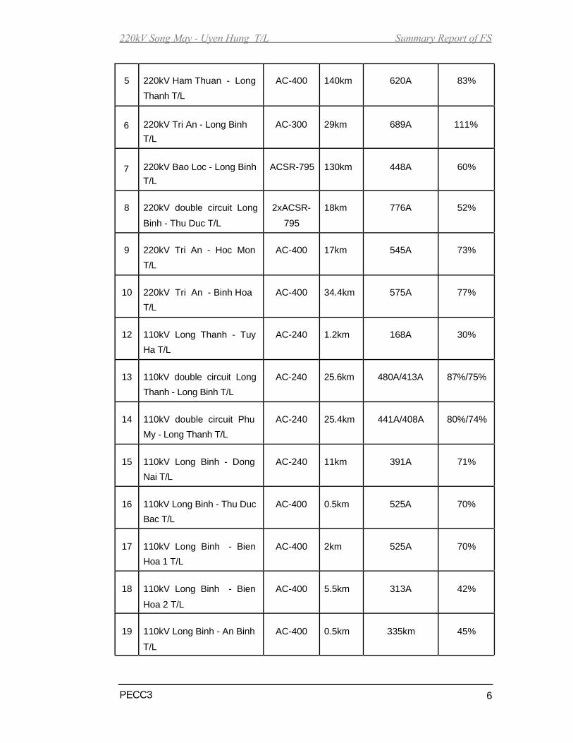
220kV Song May - Uyen Hung T/L Summary Report of FS
5 220kV Ham Thuan - Long AC-400 140km 620A 83%
Thanh T/L
6 220kV Tri An - Long Binh AC-300 29km 689A 111%
T/L
7 220kV Bao Loc - Long Binh ACSR-795 130km 448A 60%
T/L
8 220kV double circuit Long 2xACSR- 18km 776A 52%
Binh - Thu Duc T/L 795
9 220kV Tri An - Hoc Mon AC-400 17km 545A 73%
T/L
10 220kV Tri An - Binh Hoa AC-400 34.4km 575A 77%
T/L
12 110kV Long Thanh - Tuy AC-240 1.2km 168A 30%
Ha T/L
13 110kV double circuit Long AC-240 25.6km 480A/413A 87%/75%
Thanh - Long Binh T/L
14 110kV double circuit Phu AC-240 25.4km 441A/408A 80%/74%
My - Long Thanh T/L
15 110kV Long Binh - Dong AC-240 11km 391A 71%
Nai T/L
16 110kV Long Binh - Thu Duc AC-400 0.5km 525A 70%
Bac T/L
17 110kV Long Binh - Bien AC-400 2km 525A 70%
Hoa 1 T/L
18 110kV Long Binh - Bien AC-400 5.5km 313A 42%
Hoa 2 T/L
19 110kV Long Binh - An Binh AC-400 0.5km 335km 45%
T/L
PECC3 6

220kV Song May - Uyen Hung T/L Summary Report of FS
20 110kV An Binh - Amata T/L AC-400 2.5km 112km 15%
21 110kV Long Binh - Xuan AC-240 44.65km 400A 76%
Truong T/L
22 110kV Tri An - Dinh Quan AC-185 53.7km 112A 24%
23 110kV Tri An - Tan Hoa AC-240 17km 142A 31%
T/L
24 110kV Tri An - Dong Xoai AC-185 60.7km 168A 37%
2.1.2. Existing Binh Duong province’s power sources and electrical network
Presently, Binh Duong province’s exiting electrical network are supplied from
power sources such as:
- Thac Mo hydropower plant (2x75MW). - Can
Don hydropower plant (2x38,8)MW. - Tri An
hydropower plant (4x100MW).
- Thu Duc thermal power plant (2x37,5MW). -
VSIP power plant (12MW).
The existing transmission lines at Binh Duong province are as follows:
No. Name of transmission line Conductor Length
1 220kV Double circuit Tri An - Binh Hoa T/L AC-400 37km
2 220kV Long Binh - Thu Duc T/L ACSR -795 18.3km
3 220kV double circuit Tan Dinh - Binh Hoa 2xAC-300 10.63km
T/L
4 220kV double circuit Tan Dinh - My Phuoc AC-400 15.4km
T/L
PECC3 7

220kV Song May - Uyen Hung T/L Summary Report of FS
5 220kV-110kV four-circuit Thu Duc - Long ACSR 18.3km
Binh upgraded T/L 795MCM
6 220kV double circuit Tan Dinh - Trang ACSR 40km
Bang T/L 795MCM
7 110kV Thu Duc - Song Than T/L ACSR- 10.9km
397MCM
8 110kV VSIP - Song Than T/L AC-240 7.2km
9 110kV Binh Hoa - VSIP T/L ACSR 5.3km
397MCM
10 110kV Binh Hoa - Go Dau T/L ACSR 7.4km
795MCM
11 110kV Thac Mo- Ben Cat- Hoc Mon T/L AC-185 165km
12 110kV Thac Mo - Tay Ninh T/L AC-185 268km
13 110kV Tri An - Dong Xoai T/L AC-185 129km
14 110kV Dau Tieng substation and double AC-185 2.5km
circuit branch line
15 110kV Phu Giao substation and double AC-185 1.3km
circuit branch line
16 110kV double circuit Binh Hoa - Tan Dong AC-240 7.5km
Hiep T/L
17 110kV Tan Dong Hiep - Sunsteel T/L AC-185 2.2km
18 110kV Binh Hoa - Tan Uyen T/L AC-240 14.7km
19 110kV My Phuoc - Kumho T/L AC-400 4.8km
20 110kV Kumho - Ben Cat 1 T/L AC-400 3.9km
AC-185 1.5km
PECC3 8

220kV Song May - Uyen Hung T/L Summary Report of FS
21 110kV My Phuoc - Ben Cat 2 T/L AC-400 8.7km
AC-185 4.5km
22 110kV My Phuoc - Chon Thanh T/L AC-400 7.4km
AC-185 15.1km
2.2. Power source expansion planning and transmission line expansion planning Dong
Nai province ’s electrical system
According to Dong Nai’s power network plan in 2005-2010 (up to 2015)
approved by Ministry and Industry by letter No. 2984/QĐ-BCN dated on
23/9/2005, power source expansion planning and transmission line
expansion planning is as follows:
Stage 2006-2010:
Substations:
- 500kV substations: new construction 500/220kV Song May
substation (3x200MVA) (including 220kV substation - 1x125MVA) is
supplied by sources of Phu My power plant.
- 220kV Xuan Loc substation: new construction 220kV Xuan Loc
substation (1x250MVA) is supplied by sources of 500/220kV Song
May substation.
- 220kV Long Thanh substation: upgrade from 1x250MVA to
2x250MVA.
- 110kV substations: new construction of 16 substations with capacity
is 671MVA.
Transmission lines:
- New construction of 500kV Phu My - Song May transmission line
PECC3 9

220kV Song May - Uyen Hung T/L Summary Report of FS
- Construction of 220kV transmission line connecting with 220kV Tri
An - Long Binh transmission line.
- Construction of 220kV double- circuit Nhon Trach - Nha Be
transmission line.
- Construction of 220kV double-circuit Nhon Trach - Cat Lai
transmission line.
- Construction of 110kV transmission lines such as: connection lines of
500kV Song May, Xuan Loc - Cam My, Xuan Loc - Dinh Quan, Tri
An - Vinh An, Long Thanh - Nhon Trach industrial zone, Vinh An -
Kiem Tan, Xuan Loc - Song May, Ong Keo - Sun Steel transmission
lines.
- 110kV branch lines: 110kV Dau Giay, Bau Xeo, Tam Phuoc, SN.
Long Thanh, Sub Steel, Quang Trung, Pou Sung, Dinh Quan 2,
AMATA 2 substations.
- Upgrading of 110kV Long Khanh - Xuan Loc transmission line.
Stage 2011-2015:
Substations:
- 500kV substations: Upgrading of 500/220kV Song May substation
from 3x200MVA to 2 (3x200) MVA.
- 220kV substations: New construction of 220kV Nhon Trach
substation (2x250MVA) and Upgrading of 220kV Xuan Loc
substation from 1x250MVA to 2x250MVA and 220kV Song May
substation from 1x125MVA to 2x250MVA.
- 110kV substations: New construction of 11 substations with capacity
is 440MVA and upgrading of 23 substations with total of capacity is
854MVA.
PECC3 10
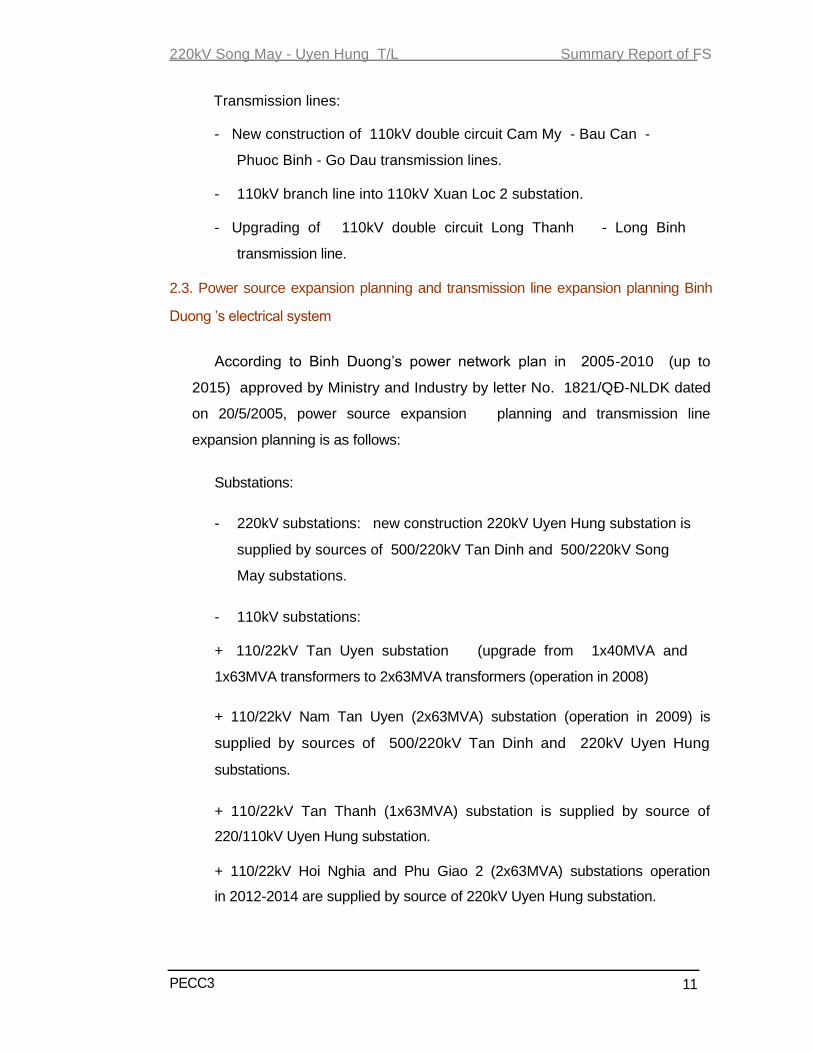
220kV Song May - Uyen Hung T/L Summary Report of FS
Transmission lines:
- New construction of 110kV double circuit Cam My - Bau Can -
Phuoc Binh - Go Dau transmission lines.
- 110kV branch line into 110kV Xuan Loc 2 substation.
- Upgrading of 110kV double circuit Long Thanh - Long Binh
transmission line.
2.3. Power source expansion planning and transmission line expansion planning Binh
Duong ’s electrical system
According to Binh Duong’s power network plan in 2005-2010 (up to
2015) approved by Ministry and Industry by letter No. 1821/QĐ-NLDK dated
on 20/5/2005, power source expansion planning and transmission line
expansion planning is as follows:
Substations:
- 220kV substations: new construction 220kV Uyen Hung substation is
supplied by sources of 500/220kV Tan Dinh and 500/220kV Song
May substations.
- 110kV substations:
+ 110/22kV Tan Uyen substation (upgrade from 1x40MVA and
1x63MVA transformers to 2x63MVA transformers (operation in 2008)
+ 110/22kV Nam Tan Uyen (2x63MVA) substation (operation in 2009) is
supplied by sources of 500/220kV Tan Dinh and 220kV Uyen Hung
substations.
+ 110/22kV Tan Thanh (1x63MVA) substation is supplied by source of
220/110kV Uyen Hung substation.
+ 110/22kV Hoi Nghia and Phu Giao 2 (2x63MVA) substations operation
in 2012-2014 are supplied by source of 220kV Uyen Hung substation.
PECC3 11

220kV Song May - Uyen Hung T/L Summary Report of FS
+ Lien Hop 3 substation (2x63MVA) is supplied by source of 500kV Tan
Dinh and 220kV Uyen Hung substations.
PECC3 12

220kV Song May - Uyen Hung T/L Summary Report of FS
220kV and 110kV transmission lines of Tan Uyen district - Binh Duong province up to 2015
110kV T/L
220kV T/L
500kV T/L
110kV Tan Uyen
2x63MVA (2008)
500kV Tan Dinh
110kV Bau Beo
1x63MVA (2006)
110kV Phu Giao 2
2x63MVA
(20011-2015)
110kV Tan Thanh 110kV Hoi Nghia
1x63MVA (2010) 2x63MVA
(20011-2015)
220kV Uyen Hung (2010)
110kV Nam Tan Uyen
1x63MVA (2009)
110kV T3
2x63MVA (2013-2014) 500kV Song May
220kV Binh Hoa
PECC3 13

220kV Song May - Uyen Hung T/L Summary Report of FS
CHAPTER 3
LOCATION AND PROJECT SIZE
1.1. Location
The planning lines of 220 kV Song May - Uyen Hung transmission line will be built
starting from Trang Bom district, Dong Nai province, ending at Uyen Hung town, Binh
Duong province.
1.2. Project size
220 kV Song May - Uyen Hung transmission line is built with following
specifications:
- Rated voltage
- Number of circuits
- Start point
- End point
- Length of the line -
Conductor
- Overhead ground wire
- Insulator
- Tower
- Foundation
- Earthing
1.3. Scope of project
:220kV
:One-circuit, two-circuit, three-circuit
One-circuit (length of 544.4 m)
Two-circuit (length of 15,277m)
Three-circuit (length of 6,401m)
:220kV busbar of 500kV Song May substation.
:220kV busbar of 220kV Uyen Hung substation
:21,678 m
:2xACSR 330/43 (for 220kV Song May - Uyen Hung T/L)
: 1xACSR-400/52 (for 220kV connection line)
:Optical ground wire - OPGW186 (type 24 fibers)
and overhead ground wire -PHLOX181.6”.
: 70kN, 100kN insulator disc for conductor suspension
string; 160kN, 300kN insulator disc for conductor
tension string.
:G alvanized Steel towers.
: Steel concrete in - situ cast.
-
2.000 in every tower.
Scope of project is all of Song May - Uyen Hung transmission line from 220kV
busbar of 500kV Song May substation at Bac Son commune, Trang Bom
PECC3 14
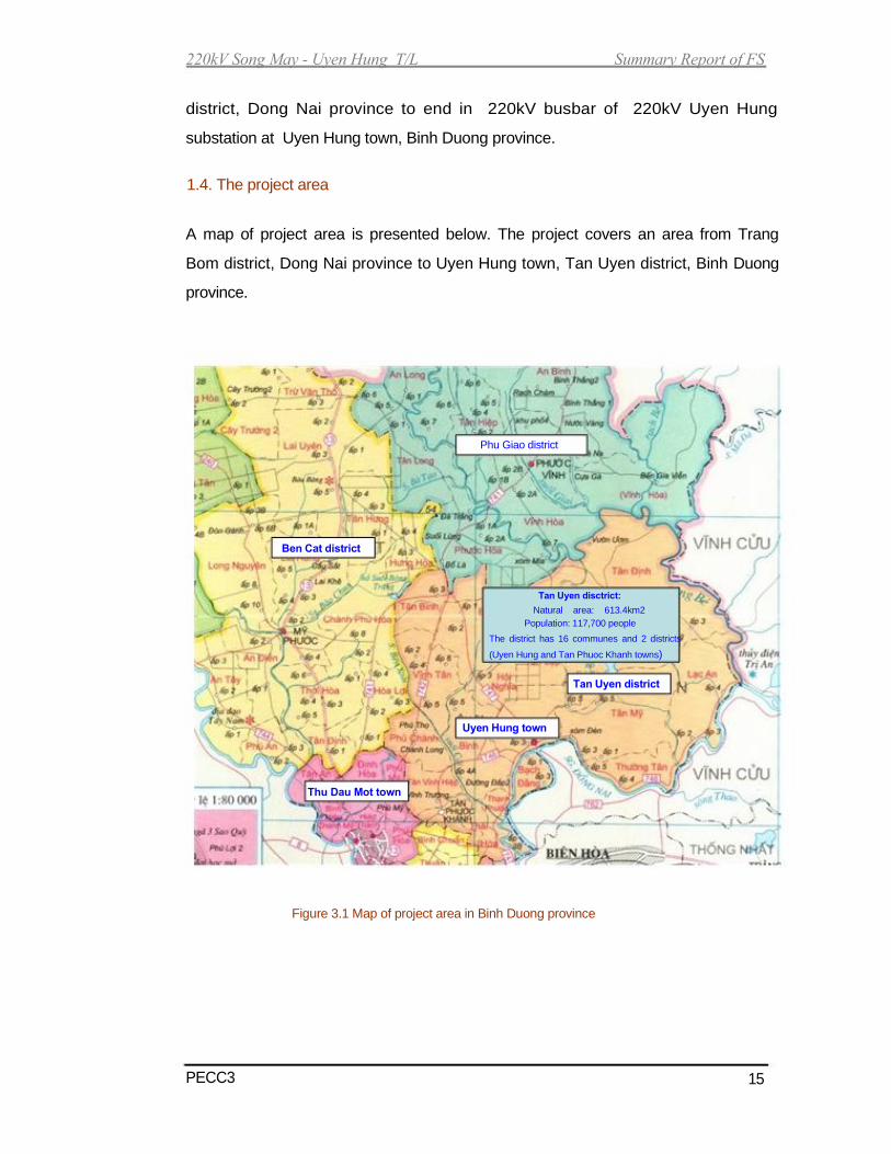
220kV Song May - Uyen Hung T/L Summary Report of FS
district, Dong Nai province to end in 220kV busbar of 220kV Uyen Hung
substation at Uyen Hung town, Binh Duong province.
1.4. The project area
A map of project area is presented below. The project covers an area from Trang
Bom district, Dong Nai province to Uyen Hung town, Tan Uyen district, Binh Duong
province.
Phu Giao district
Ben Cat district
Tan Uyen disctrict:
Natural area: 613.4km2
Population: 117,700 people
The district has 16 communes and 2 districts
(Uyen Hung and Tan Phuoc Khanh towns)
Tan Uyen district
Uyen Hung town
Thu Dau Mot town
Figure 3.1 Map of project area in Binh Duong province
PECC3 15
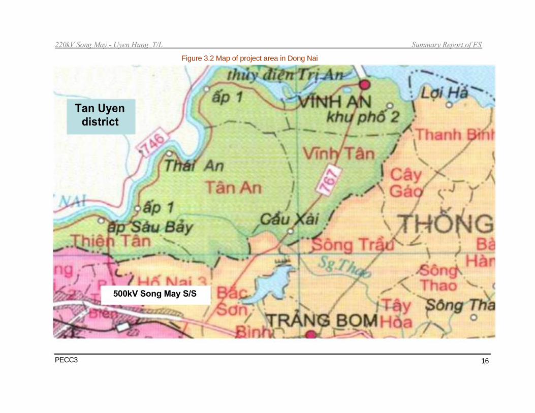
220kV Song May - Uyen Hung T/L Summary Report of FS
Figure 3.2 Map of project area in Dong Nai
Tan Uyen district
500kV Song May S/S
PECC3 16

220kV Song May - Uyen Hung T/L Summary Report of FS
CHAPTER 4
LOAD FORECASTING
The forecast of load demands of Dong Nai province is showed in table 4.1
Table: 4.1 Unit: GWh
Load Type 2010 2015
Agriculture - Silviculture - Aquiculture 24.6 32.9
Industry -Construction 4,776.6 9,485.7
Commerce - Hotel - Restaurant 288.3 669.1
Resident -Public Administration Offices 955.5 1,397.7
Other consumer
Total 6,045.1 11,582.4
The forecast of load demands of Binh Duong province is showed in table 4.2
Table: 4.2 Unit: GWh
Load Type 2010 2015
Agriculture - Silviculture - Aquiculture 15.8 31.9
Industry -Construction 1,261.7 2,030.7
Commerce - Hotel - Restaurant 219.9 899.4
Resident -Public Administration Offices 1,034.7 1,935.8
Other consumer 188.8 536.3
Industrial zones 3,952.1 6,867.2
Total 6,672.9 12,301.3
PECC3 17

220kV Song May - Uyen Hung T/L Summary Report of FS
CHAPTER 5
TECHICAL SOLUTIONS
5.1. Transmission line
5.1.1. Line route alternatives
The alternatives of lines have basic characteristics as follows:
- Start point: 220kV busbar of 500kV Song May substation.
- End point: 220kV busbar of 220kV Uyen Hung substation
220kV Song May - Uyen Hung transmission line from 220kV busbar of 500kV Song
May substation at Bac Son commune, Trang bom district Dong Nai province
to end in 220kV busbar of 220kV Uyen Hung substation at Uyen Hung town, Binh
Duong province.
Alternative 1: The length of line route is 21.4km.
Alternative 2: The length of line route is 23.5km.
Alternative 3: The length of line route is 21.67km.
5.1.2. Comparison of line route alternatives
Based on the meeting with People’s Committee of Dong Nai and Binh
Duong, line route is approved to run parallel with 500kV Song May - Tan
Dinh transmission line in order to decrease land area affected and affected
houses within right of way (ROW). Therefore, the alternative 3 is chosen.
5.1.3. Comment
Based on the above comparison of alternatives, alternative 3 is the most
optimal. The line route of alternative 3 is chosen. The line route of alternative 3
goes through areas with features as follows:
PECC3 18

220kV Song May - Uyen Hung T/L Summary Report of FS
a) Trang Bom district ’s area: From start point ĐĐ1 to G0 section.
- The line route from the start point near 500kV Song May substation to G0
is about 173,3m. The line goes on land to belong to Bac Son commune,
Trang Bom district - Dong Nai province. There are not any affected
houses within ROW in the route section.
b) Vinh Cuu district ’s area:
- The route of line from G0 to G1 is about 1,723.7m, the route runs parallel
with connection line of 220kV Tri An - Long Binh transmission line. The route
goes through Tan An commune, Vinh Cuu district - Dong Nai province.
The line route goes across indigo, rubber trees. There are 6 houses in
ROW.
- The route of line from G1 to G2 is about 1,422.4m, the route goes
through Tan An commune, Vinh Cuu district - Dong Nai province. The
line route goes across cajuput., cashew tree, rice - field. There is not
affected house in ROW.
- The route of line from G2 to G3 is about 2,054.3m, the route goes also
through Tan An commune, Vinh Cuu district - Dong Nai province. The
line route goes across cajuput, rice - field. There are not affected houses
in ROW.
- The route of line from G3 to G4A is about 1,200.1m, the route goes also
through Tan An commune, Vinh Cuu district - Dong Nai province. The
line route goes across cajuput, rice - field. There is one affected house in
ROW.
- The route of line from G4A to G5B is about 190m, the route goes also
through Tan An commune, Vinh Cuu district - Dong Nai province. The
line route goes across rice - field. There is not affected house in ROW.
-The route of line from G5B to G6 is about 2307.1m, the route runs
parallel with 500kV Phu My - Song May transmission line. The line
route goes across cajuput, rice - field, some agricultural produce, 220kV
Tri An - Hoc Mon T/L, 110kV Tri An - Tan Hoa T/L and Dong Nai
province. The line section goesTan An commune, Vinh Cuu district,
Dong Nai province. It also goes through Thuong Tan commune, Tan
PECC3 19
220kV Song May - Uyen Hung T/L Summary Report of FS
Uyen district, Binh Duong province with length of 380m .There are 12
affected houses in ROW.
c) Tan Uyen district ’s area:
- The route of line from G6 to G7 is about 5,041.9m, the route runs parallel
with new 500kV Song May - Tan Dinh transmission line. The route goes
through Thuong Tan, Tan My communes, Tan Uyen district, Binh Duong
province. The route goes across some cajuput, rice-field and rubber trees.
There are 2 affected houses in ROW.
- The route of line from G7 to G8B is about 654.9m. The route goes across
rubber trees, some indigo trees. It goes Tan My commune, Tan Uyen
district, Binh Duong province. There are no affected houses in ROW.
-The route of line from G8B to G9 is about 875.1m. The route goes across
some rubber trees. It also goes Tan My commune, Tan Uyen district,
Binh Duong province. There are only one affected houses in ROW.
-The route of line from G9 to G11 is about 3483.1m. From G9 to G10, the
route runs parallel with exsiting 500kV Pleiku-Tan Dinh transmission
line. The route goes across most rubber trees and some cajuput trees. It
also goes Tan My commune, Tan Uyen district, Binh Duong province.
There are no affected house in ROW.
- The route of line from G11 to G12 is about 1912.9m. The route goes
across most rubber trees. It also goes Tan My commune, Tan Uyen
district, Binh Duong province. There are two affected houses in ROW.
-The route of line from G12 to ĐC is about 577.3m. The line goes along
with DH411 street and across most cajuput trees and then connect into
220kV Uyen Hung substation. The route goes through Uyen Hung town,
Binh Duong province.
Table 5.1: Summary of the 220kV Song May - Uyen Hung tranmission line’s
length and deviation angle. No. From point to point Length Deviation angle Remark
(m)
1 220kV Busbar of 31.5 500kV Song May substation
500kV Song May
substation - ĐD1
PECC3 20

220kV Song May - Uyen Hung T/L Summary Report of FS
2 ĐD1 - G0 173.3
3 G0 - G1 1723.7 L 7º31'44",
4 G1 - G2 1422.4 R67º59'42"
5 G2 - G3 2054.3 L61041'43"
6 G3 - G4A 1200.1 L29016'59”
7 G4A - G4B 78.9 R77 052'11"
8 G4B - G5A 48 R14049'54"
9 G5A - G5B 63.1 L81053'22"
10 G5B - G6 2307.1 L 8º01' 29”
11 G6 - G7 5041.9 R28º11'46"
12 G7 - G8A 606.1 R31º09'54"
13 G8A - G8B 48 R6º58'27"
14 G8B - G9 875.1 L78043' 29"
15 G9 - G10 1596.8 L7º47' 30"
16 G10 - G11 1886.3 R8015’41”
17 G11-G12 1912.9 R1º50' 52"
18 G12 - ĐC 577.3 L36º41'46"
19 ĐC-220kV busbar 30.5 220kV Uyen Hung substation
of 220kV Uyen
Hung substation
Total (m) 21,678
Table 5.2: Summary of the 220kV connection line’s length with 220kV exsting
Tri An - Long Binh transmission line and deviation angle. No. From point to point Length Deviation angle Remark
(m)
1 220kV Busbar of 50 500kV Song May substation
500kV Song May
substation - ĐD2
2 ĐD2 - G0 119.8
3 G0 - G1 1723.7 L 7º31'44",
4 G0 - G4A 6400.5 R10055’57” The same route as 220kV
Song May - Uyen Hung line
section
5 G4A - G4A1 76.6 R98033’03”
6 G34A1- G4A2 48 L5050’57”
7 G4A2 - G4A3 250 R2051’00”
Total (m) 6,945
PECC3 21

G 1 0 B
B T1 2 -8
B T
B T8 - 9
220kV Song May - Uyen Hung T/L Summary Report of FS
220kV Uyen Hung Sub. L t.Ch i? n Khu D 43 ,0 27 ,4
22 ,6
16 ,5
500kV Pleiku
- Tan Dinh 15 ,8
54 ,2
110kV Tri An - Tan Hoa
37 ,0
42 ,6 G12
cao lanh 44 ,5 37 ,4
32 ,6 44 ,8
40 ,8 c ao lanh 31 ,5
35 ,5
33 ,5 34 ,4
29 ,4 43 ,9 36 ,2
49 ,3
1415 ,1 léi
22 ,8 39 ,8 46 ,8 42 ,8 43 ,9
35 ,4 31 ,0
53 ,4 1563
13 ,7 29 ,0
53 ,7 60 ,2 53 ,4 10 - 8 10
51 ,5
45 ,3 10 ,5 20 ,5
22 ,8 9 ,5 53 ,0 57 ,4
47 ,3 44 ,7 9 ,5 56 ,5
Đ C 43 ,5 37 ,7 37 ,9 39 ,8 24 ,0 1 ,4 6 ,6 26 ,2
26 8 ,5
2 A 44 ,5
44 ,2 39 ,1
46 ,8 44 ,7 G11 44 ,0 41 ,0
46 ,2 21 ,0 45 ,7
L t.Ch iÕ n Khu D 39 ,5
44 ,4
G10 G9 41 ,6
47 ,8 48 ,4
51 ,0 55 ,5 40 ,8
49 ,1
39 ,3 62 ,0 54 ,6
31 ,5 26 38 ,5 58 ,2 9 ,6
15 ,2 14 ,0 2 ,0 49 ,3
12 ,3 46 ,5
c ? u R ? c h C ? t léi 18 -7 B T30 5 ,9
12 ,0 44 ,5 36 ,7 14 ,5
7 ,8 59 ,5
42 ,2 G 31 ,9 43 ,6
25 40 ,7 44 ,7 25 29 ,1 9 ,2 13 ,5 50 ,4
12 ,4 33 ,0 8B G8A
37 ,2 20 ,5 11 ,4 12 ,7
61 ,5 64 ,2 41 ,5 10 ,2
53 ,7 8 ,5 12 ,0 49 ,0 1 ,4 1 ,4 R 29 ,8
25 16 ,4 ? p 4 27 -8 9 ,0
c ? u B ? G i?B T 30
31 ,5 25 11 ,3 29 ,0 12 ,8
26 ,8 17 ,0 mi? u X ? m ? ? n 14 ,2
24 2 -4 25 -3 4 ,4 9 ,8 B T3 10 4 ,5
miÕu 5 ,1 10 ,8 33 ,5 L ong ChiÕn 6 ,3 9 ,5 1025
- 0 ,3 98 99 00 3 ,7 01 02 5 ,6 03
5 ,6 16 ,0
mi? u B? 2 ,8 4 ,1
23 5 ,3 2 ,4
51 ,0
G 1 2 44 ,6
41 ,5
21 ,5
04
22 ,0
13 ,5
G 42 ,8 7 15 ,2 13 ,5
05
25 ,5 43 ,5
2 ,0 8 ,3 51 ,2
48 ,5 36 ,6 47 ,7 8 ,5
48 ,3 39 ,2 23 ,2 2 ,5 9 ,6 8 ,3
2 ,5
06 07 08 8 ,5 09
9 ,5
7 ,4 7 ,7
8 ,4 31 ,5 8 ,5 59 ,8 10 ,7 9 ,8 10 ,2 54 ,0
ub 50 ,5
24 11 ,2
46 ,7 c ? u ? ng T ? ng 61 ,0 8 ,6 9 -8 8 ,8 B T30 53 ,1 54 ,5
8 ,4 10 8 ,5 1 ,4 11 12 10 ,7 13 14 15
6 ,3 50 ,5 56 ,0 38 ,0 65 ,3
9 .0 24 -8 9 ,3 35 ,6 38 ,4 23 1 ,4
b ¬m 2 ,0 13 ,5 8 ,2 22 ,8
9 ,4 chî 24 -8 26 ,8 35 ,6
35 ,
,3 7 ,0 38 ,5 6 ,5 6 ,9 B T25 c Çu C hïn Bao 9 ,5
8 ,3 Ub 3 ,5
15 ,2 24 ,0
16 ,5 31 ,3 6 ,5 28 ,2 T h i An
3 ,8 3 ,2 10 ,5 7 ,1
10 ,4 5 ,0 10 1 -B 8 ,4 34 ,8
9 ,6 7 ,6 23 ,4
27 ,2
mi? u B? 24 -3c Çu R ¹ c h 4 ,6 Trè 3 ,4 11 ,5 14 ,0
7 ,6 49 ,5
45 ,0 25
14 ,8 11 ,4 12 s ©n 49 ,5 25 ,5
22 8 ,6 8 ,2 10 ,6 25 1 -B 6 ,5 22 49,8
4 ,7 7 ,8 4 ,5
Ch .B ? nh L ong 10 ,4 9 ,5
Ub 1250 4 ,5 4 ,8 7 ,1
3 ,8 8 ,5
6 ,6 15
,5
500kV Song
21 ,3
Mây 9 ,4
? ? s 4 0 -4 30
27 ,2 13 ,3 1 ,4 7 ,6
6 ,7 8 ,9 17 ,2 55 ,1 56 ,2
c Çu § ¹ i A n 47 ,0 46 ,0
26 ,3 36 ,8
10 ,3 10 ,6 10 ,5 10 ,2 ? ? n h B ? nh L ? i 2 ,7 11 ,8
21 7 ,8 4 ,2 7 ,1 4 ,9
4 ,5 29 ,5 5 ,6
--- Ta n Dinh 9 ,3
26 ,3 ® ? ? G6
5 ,5
19 - 8B T 25 15 ,3 11 ,5 49 ,2
20 ,8 33 ,5 21 12 ,3
9 ,7 6 ,2
3 ,9 6 ,4
2 ,0 3 ,8 6 ,3
7 ,4 17 ,5 59 ,1 59 ,4 25
3 ,3 ? ? - 0 ,3 - 0 ,4 7 ,1 7 ,5 5 ,8
cÇu Bµ § Æng 4 ,5 ®
5 ,3 6 ,6 5 ,5
G 1 1
8 ,7
L .s? 23 ,8
ub G5B G5A
16 ,8 22 ,2 26 ,4
G4A.3 52 ,2 18 ,2
51 ,5
9 ,1
5 ,2 ? .B ? nh L ? i 5 ,2 13 4 ,8 9 ,7 2 -B
20 3 ,8
b ? m - 0 ,4 2 ,5 9 ,2
4 ,9 7 ,3
3 ,8
4 ,5 6 ,2 933 7 ,4
7 ,3 Ub
10 ,6 10 ,8 7 ,1 7 ,4
3 ,2
4 ,7
6 ,8
6 ,5 1 ,3
1 ,3
10 ,8 9 ,4
6 ,4 G 4B
5 ,7
G 4A.2 G4A.1 6 ,9
10 ,4 20 8 ,2
55 ,5 lé i
1576 22 ,0 8 ,1 9 ,5
15 ,4
8 ,2 ? p 2 47 ,7
g ¹ ch 2 ,5 5 -3
S 2 ,5 11 ,2
10 6 ,1
19 1 -B
6 ,2 24 -8 8 ,3 7 ,7 7 ,1
8 ,3 18 -4 6 ,8 B T30 NM n −íc 7 ,5 g ¹ch
8 ,8 7 ,3 6 ,2 c Çu R ¹ c h T «m B T 63 -8 5 ,9
29 -8 B T25 30 5 ,6
G4A 13 ,1
? p 3 G 3
13 ,1
19
8 ,1 8 ,9
13 1 -B
8 ,3 10 ,3
3 ,1
3 ,0 220 KV 3 ,9
4 ,8
2 ,5
9 ,5 19 ,8
ÑÖÔØNG DAÂY 220 kV TRÒ A N - HOÙC 17,5OÂN
T rg .C .N
15 ,7 c ? ? i? n
7 ,0 c ? u R ? c h ? ? ng 5 ,7 6 ,2 Ub 7 ,5 11 ,1 8 ,3
7 ,4
g ? ch 4 ,4
B T12 -8 V 9 ,5 C .B öu S ¬n 12
14 ,7 17 ,7 g ¹ ch 7 ,8
g ¹ ch 15 1 -B 5 ,8 13 1 -B
5 ,2 4 ,6
5 ,2
Truï soá
5 ,6
12 ,8
9 ,5
Êp 3
8 ,3
23 ,2 8 ,4
G2 ? p 3 Êp 3 14
46 ,5 18 ,5 1 -B
c ? u T ? n Tr ¹ ch L .s ? 22 ,1 ® 6 ,2 10 ,5 Êp 3 6 ,2
18 220kV Ub c h?
3 ,7 ? .T ha nh Ph ?
8 ,1
Tri g ? ch
27 ,2 2248
23 ,5 23 ,8 An 38 ,5
X.N .giÇ y da 36 ,2
45 ,8 c ao lanh 46,1 23 ,1
g ¹ ch tr ? i g ? 44 ,9 50 ,3
9 ,7 30 6 ,9 18 10 ,5 13 ,8 47 ,0 9 ,8
52 ,1 49 ,0 4 ,8 10 ,1
7 ,2 o ng C ? T ? --- H oc Mon
12 ,5 17 ,2
X.N .b ª t« ng 45 ,9 924 14 ,4 55 ,1
®ang sa n lÊp 37 ,5 17 ,9 5 ,3 53 ,8
20 ,7 31 ,3 ? ? 31 ,5 53 ,8
bi? n36 h? a 17 2 ,8 C-48 -3 4 -B -a
4 ,5 C - 4 8 -2 2 - D - c 98 X.N . èc vÝt 99
0 ,3 km ? p 4 - 1 ,2 km
19 ,3 32 ,7 21 ,4 10 ,9
487 00 0126 ,6 02 t.p . bi ? n h? a 03 x ? T? n B? nh x· T© n B×nh x· Th ¹n h Phó x ? Th ? n h P h ? P v ? n h c? u 31 ,8 V ? nh C? u Ê p 4 -2 km K.p h ? 4 -1 km t .p .b i? n h? a 28 ,2
40 ,4 55 ,3 61 ,0
40 ,2 p h − ên g Tr ¶n g D µi 487 04 50 ,1 P h .T r? ng D? i 40 ,6 58 ,8
10 ,7 5 ,8
220kV Tri An 8
,6
0 ,8 10 ,8
G1 17 17 ,2 25
10 ,8 34 ,6 54 ,1 18 ,6 12 ,3 x ? Th i? n T? n x ? T? n A n 41 ,7
51 ,7
3 , G 9A
,7 km ch ? a B ? nh Y 0 ,2 km 98 99 12 ,8 487 24 ,20 27 ,2 01 02 03 487 04 46 ,3 53 ,5 51 ,2 --- 15 ,9 Lo 17 ,2 22 ,6
4 ,9 1723 32 ,8 38 ,9 42 ,9
42 ,7 K .ph ? 50
40 ,1 38 ,3 ng Bin h 30 ,4
9 ,5 47 ,6 16 ,9
50 ,2 23 ,4 43 ,3
44 ,4 49 ,2 40 ,3 50 ,7
2 ,8 16 25 ,7 21 ,2 27 ,8
10 ,3 1 ,3 40 ,0 7 ,5
42 ,6 2003 theo c? c t? i l i ? u: Ub in n ? m 1 99 6,1 99 7 32 ,1 36 ,7
3649 n ? m 2 0 02 . 33 ,8 K .p h ? 43 ,6 10 34 ,1 32 ,3
16 13 ,8 ? ng H ? i 2 ? ? ng H ? i 2 14 ,3 19 ,2 46 ,1
10 ,4 4 ,3 G0
53 ,4
50 ,5 1 ,5 ? o b ? i ? ? o b ? i
500kV Song May
Figure 5.1: 220kV Song May - Uyen Hung transmission line route (Alternative 3)
PECC3 22

220kV Song May - Uyen Hung T/L Summary Report of FS
5.1.4. Transmission line layout
5.1.4.1 General
5.1.4.1.1 Climatic conditions
Climatic conditions are as follows:
Air temperature:
Minimum air temperature 15oC
Yearly average air temperature 30oC
Maximum air temperature 40oC
Air temperature at maximum wind velocity 25oC
Air temperature in thunder 20oC
Wind pressure:
The design maximum wind pressure at 10 m elevation is 60 daN/m2
Atmospheric conditions:
Average humidity : 80%
Pollution level:
The pollution levels in accordance with IEC is: 2.0cm/kV
5.1.4.2. Conductors
Conductors for 220kV Song May - Uyen Hung transmission line are used
ACSR 330/43.
Cross-section:
+ Aluminum :332m2
+ Steel :43.1mm2
+ Total :375.1mm2
Calculated diameter :25.2mm
Weight (total) :1.255 kg/m
Rated tensile strength (RTS) :103,784N
Elastic module :7,034daN/mm2
PECC3 23

220kV Song May - Uyen Hung T/L Summary Report of FS
Heat elasticity coefficient :19.3x10-61/0C
Conductor for 220kV connection line to 220kV Tri An - Long Binh Line
are used ACSR 400/52.
Cross-section:
+ Aluminum :400m2
+ Steel :51.9mm2
+ Total :452m2
Calculated diameter :27.6mm
Weight (total) :1.510 kg/m
Rated tensile strength (RTS) :12300daN
Elastic module :7,034daN/mm2
Heat elasticity coefficient :19.3x10-61/0C
5.1.4.3. Earthwires
Earthwire for 220kV Song May - Uyen Hung transmission line is used
PHLOX 181.6:
Cross-section :181.63mm2
Calculated diameter :17.5mm
Weight (total) :975 kg/km
Rated tensile strength (RTS) :16024daN
Elastic module :12,400daN/mm2
Heat elasticity coefficient :14.2x10-61/0C
5.1.2.4. Overhead Ground Wire Fiber (OPGW)
OPGW for 220kV Song May - Uyen Hung transmission line is OPGW186 with
fibre in accordance with ITU-T G.652 (24 fibers).
5.1.2.5. Insulators
The suspension and tension insulator string units shall be of the cap and pin
type and shall comply in all respects with IEC 60305, IEC 60383 and IEC
60120. Insulator units shall be of glazed porcelain or tempered glass type.
PECC3 24
220kV Song May - Uyen Hung T/L Summary Report of FS
5.1.4.6. Tower
Towers are used steel lattice tower type for 1 circuit, 2 circuits and 3
circuits.
5.1.4.7. Foundation
Foundations are designed to be suitable for the ground conditions.
Foundation type which is recommended for 220kV Song May - Uyen
Hung transmission line is individual footing foundation.
PECC3 25
220kV Song May - Uyen Hung T/L Summary Report of FS
CHAPTER 6
PROJECT EXECUTION
10.1. Project management
d) Investor: National Power Transmission Corporation (NPT)
e) Project management: Southern Viet Nam Power Project Management
Board on behalf of EVN manages to carry out the project.
f) F/S carried out by Power Engineering & Consulting J.S Company No. 1
(PECC1).
g) Technical design carried out by Power Engineering & Consulting J.S
Company No.3 (PECC3).
10.2. Working progress
Working progress of the project is planned as follows.
- FS report and approval: 04/2009
- Technical design and approval: 08/2010
- Bidding documents for procurement of goods 02/2011
- Putting in operation: 12/2012
PECC3 37

220kV Song May - Uyen Hung T/L Summary Report of FS
CHAPTER 7
PROCUREMENT OF GOODS
AND REFUNDING THE BUDGET
11.1. Package of bidding documents
h) Package No.1: Supply of steel tower
i) Package No.2: Supply of conductors and overhead ground wires
j) Package No.3: Supply of insulators and Accessories
k) Package No.4: Supply of optical ground wire (OPGW) and fittings
l) Package No.5: Construction of 220kV Song May - Uyen Hung T/L.
m) Package No.6: Transport equipment and materials.
11.2. Planning progress of refunding the budget
220kV Song May - Uyen Hung transmission line is planned refunding the
budget in two years after the beginning of project.
PECC3 38

220kV Song May - Uyen Hung T/L Summary Report of FS
ANNEXES
PECC3 39