Characterization of an Optical Time Domain Reflectometer ...

www.tonercable.com
OTD-1315A Optical Time Domain Reflectometer
User’s Manual
www.tonercable.com
OTD-1315A Optical Time Domain Reflectomer
Instruction Manual
Preface
Thank you for your purchasing and using OTD-1315A series handheld optical time domain
reflectometers. This Manual mainly covers the common operation and maintenance of the instrument
and the solutions of common faults. For your convenience, before operating this instrument, please
carefully read this Manual and correctly operate it according to the instructions in this Manual.
All trademarks and names covered in this Manual are in the possession of our company, which are
used only for this instrument. Any entity or individual shall not alter, reproduce and disseminate the
contents in this Manual for any commercial purchases without the authorization.
Contents in this Manual are subject to change without notice. If you have any question, please call the
instrument supplier, and we will provide you with the best quality services!

1
Chapter 1 General
1. Unpacking Inspection
Before you receive this instrument, please carefully check the product appearance and quality
according to the packing list to find the possible damage caused in the transport process. If the
package is found damage, please keep the original packing materials, give an immediate notice
to the freight company and contact the supplier to solve this problem.
The product package should be provided with the power cord, adapter, analysis software
installation CD, user manual, etc together with the instrument, for detail, see the packing list. If
the materials in the packing box are discovered incomplete, please contact your supplier agent to
solve them in a timely manner.
2
www.tonercable.com
OTD-1315A Optical Time Domain Reflectomer
Instruction Manual
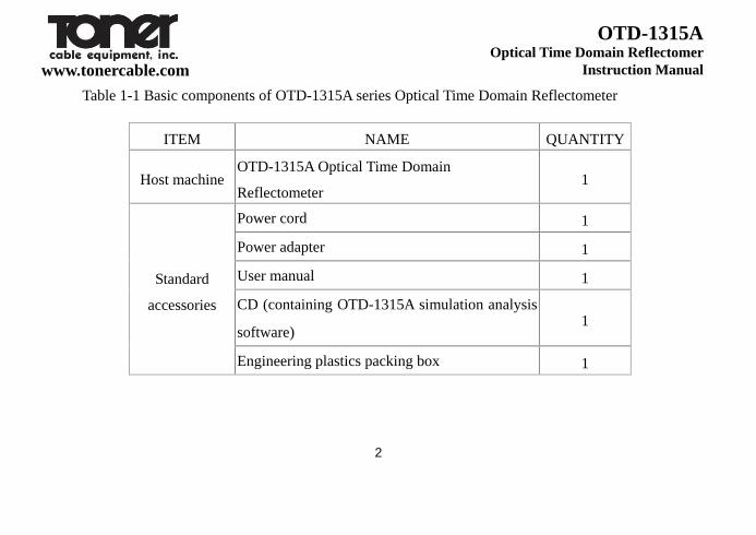
Table 1-1 Basic components of OTD-1315A series Optical Time Domain Reflectometer
ITEM NAME QUANTITY
Host machine OTD-1315A Optical Time Domain
Reflectometer 1
Standard
accessories
Power cord 1
Power adapter 1
User manual 1
CD (containing OTD-1315A simulation analysis
software) 1
Engineering plastics packing box 1
3
www.tonercable.com
OTD-1315A Optical Time Domain Reflectomer
Instruction Manual
2. Overview of Instrument
OTD-1315A series handheld optical time domain reflectometer (OTDR) is a new generation of
intelligent optical measuring instrument designed for the optical fiber communication system
test. This product is mainly used to measure the parameters of optical fibers and cables, such as
length, loss, and connection quality, etc.; it can realize the accurate positioning of event points
and fault points, and can be widely used in the construction, maintenance testing and emergency
repair of the optical fiber communication systems as well as the research, production and
production measurement of optical fibers and cables and so on. This product can provide you
with the highest performance of solutions for installation and construction of fiber optic network
construction and the subsequent fast and efficient maintenance and troubleshooting testing.
OTD-1315A has novel appearance, durable; it has the simplest interface and intuitive operation
in the OTDR industry; among the same type of handheld products, its unique dual operation
4
www.tonercable.com
OTD-1315A Optical Time Domain Reflectomer
Instruction Manual
mode of key plus touch screen can greatly simplify the user’s application; with one-key analysis,
it can quickly obtain the test results. The events are displayed in the main interface in a way of
list, and such information includes event number, type, event location (distance), loss, reflection,
event point attenuation, total loss, etc..; the whole machine adopts the intelligent power
management mode; the high capacity of lithium battery can make the whole machine working
for more than 10 hours, so it is very suitable for outdoor environments for a long time.
3. Notices
External power supply
Power adapter input meets the following requirements: 100V ~ 240V, 50/60Hz; @ 1.8A.
Power adapter output meets the following requirements: 19V ± 1V, 3.42A Polarity: center
positive.

5
www.tonercable.com
OTD-1315A Optical Time Domain Reflectomer
Instruction Manual
Please use the external power supply in strict accordance with the specification;
otherwise it may cause damage to the device.
Internal battery
Inside the instrument is the OTD-1315A Series OTDR dedicated lithium battery. To give full
play to the performance of the battery, please charge the instrument with the internal battery
and use up the electric quantity before using this instrument, and then charge the battery. The
first time of charging should be no less than 10 hours. The charging temperature range of the
battery inside the machine is 0℃~50℃. When the ambient temperature is too high,
charging will be automatically terminated for your safe use. When the instrument is not in
service for more than 2 months, timely charge it to maintain the electric quantity of the
battery; do not take out the battery without permission; do not keep the battery close to the
fire source and intense heat; do not open or damage the battery; the battery must be taken out

6
www.tonercable.com
OTD-1315A Optical Time Domain Reflectomer
Instruction Manual
when the instrument is stored for a long time. The temperature range for long term storage of
battery is -20℃~45℃.
Laser safety
When using this instrument, avoid eyes to look at the laser output port directly, nor look at
the end of the optical fiber when testing; when the instrument is not in operation, please
cover the dust cover of the optical output port.
When the visible red light of the instrument is on, please do not look at the output port of the
red light directly, nor look at the end of the optical fiber at the output end of red light
directly.
Instrument maintenance
1. The warranty period of the whole machine is 18 months and that of the battery is 6
7
www.tonercable.com
OTD-1315A Optical Time Domain Reflectomer
Instruction Manual
months. The items accompanied with the product are not within the warranty scope.
2. The light output connector of the instrument is quick-wear part, which is not within
the warranty scope.
3. If the instrument is damaged or in performance reduction caused by irresistible
external factors, they will not be within the warranty scope.
4. If the instrument is damaged or in performance reduction caused by improper
operation, they will not be within the warranty scope.
5. Users are forbidden to dismantle this instrument without the permission of the
company or designated authorized entity; otherwise, it will lose the
qualification of warranty permanently!
Return of Instrument
If the product needs to be returned due to product calibration or other reasons, please

8
www.tonercable.com
OTD-1315A Optical Time Domain Reflectomer
Instruction Manual
contact your supplier in advance and briefly explain the reasons for product return, so as
to provide effective and timely services for you.
When returning your product, please notice that:
Pack the instrument with polyethylene and other soft thin cushion to protect the
completeness of the instrument shell;
Please use the original hard packing box. If other package is used, ensure that there is
at least 3 mm thick of soft object around the instrument;
Fill out the warranty card correctly, including the company name, address, contact
person, contact phone, problem description, etc.;
Deliver the products to the supplier’s agent in a reliable way.
9
Chapter 2 Basic Operation of OTD-1315A OTDR
1. Introduction
OTDR is a precise optical measuring instrument made according to the backscatter principle of
Rayleigh scattering and Fresnel reflection when the transmission of laser in the optical fiber. It
can be widely used in the installation and construction, maintenance and repair and monitoring
application of optical fiber and fiber cables. It can be used to measure the length, attenuation,
connection quality and fault location of optical fibers and cables, etc.
When transmission of light in the optical fiber, the optical pulses in the optical fiber transmission
will generate Rayleigh scattering due to the defects of optical fiber and non-uniformity of the
mixed components. Of which, a part of light signal will be scattered back along the direction
opposite to the incident pulse, therefore, it is called backward Rayleigh scattering. Through
10
www.tonercable.com
OTD-1315A Optical Time Domain Reflectomer
Instruction Manual
observing the intensity changes of backward Rayleigh scattering light signal, the loss
distribution, connection quality and other features of optical fibers and cables can be accurately
measured. Besides, according to the theory of optical transmission, when the light encounters the
boundary of the two transmission media of different refractive indices in the transmission
process (for example, connectors, mechanical connection, fracture or optical fiber termination
points), Fresnel reflection phenomenon may occur. Through receiving the Fresnel reflection
signal on regular basis, the position of the discontinuity points along the length of the optical
fiber can be accurately determined. The size of reflection depends on the refractive index
difference and boundary surface flatness.
2. Description of the OTDR test event type
OTDR test event refers to the abnormal points that may cause loss or a sudden change in the
reflected power, including various types of connection and bending, cracks or fracture in the

11
www.tonercable.com
OTD-1315A Optical Time Domain Reflectomer
Instruction Manual
fiber link, which may cause the transmission signal loss.
The OTDR test events are mainly divided into two types: reflection events and non-reflective
events.
2.1 Reflective event
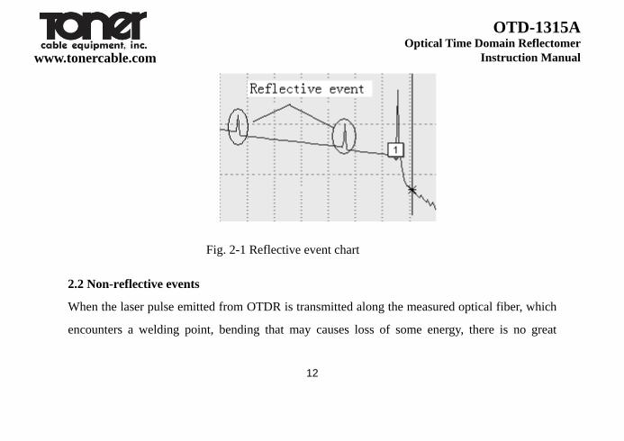
When the laser pulse emitted from OTDR is transmitted along the measured optical fiber, which
encounters a mechanical connection point or the end of the optical fiber, reflection phenomenon
will occur due to the change of the refractive index, and some of the light energy will return
along the optical fiber to the instrument. Through receiving this reflected signal, the instrument
will detect this reflection event, which will be presented as upward spike signal of a certain
width in the curve. The width of the spike is mainly determined by the width of the tested pulse,
as shown in Fig. 2-1.
12
www.tonercable.com
OTD-1315A Optical Time Domain Reflectomer
Instruction Manual
Fig. 2-1 Reflective event chart
2.2 Non-reflective events
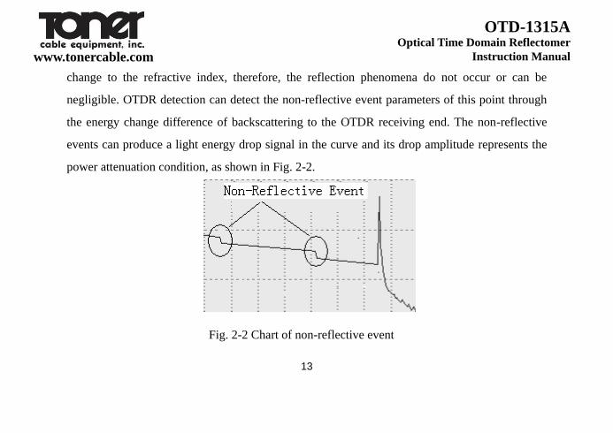
When the laser pulse emitted from OTDR is transmitted along the measured optical fiber, which
encounters a welding point, bending that may causes loss of some energy, there is no great
13
www.tonercable.com
OTD-1315A Optical Time Domain Reflectomer
Instruction Manual
change to the refractive index, therefore, the reflection phenomena do not occur or can be
negligible. OTDR detection can detect the non-reflective event parameters of this point through
the energy change difference of backscattering to the OTDR receiving end. The non-reflective
events can produce a light energy drop signal in the curve and its drop amplitude represents the
power attenuation condition, as shown in Fig. 2-2.
Fig. 2-2 Chart of non-reflective event
14
www.tonercable.com
OTD-1315A Optical Time Domain Reflectomer
Instruction Manual
3. Description of OTD-1315 series OTDR interface
3.1 Optical connection ports of OTD-1315 OTDR
The optical connection ports of OTD-1315 OTDR can be divided into OTDR output interface
and visible red light output port, which both adopt FC/PC optical connector (can be changed to
SC/PC and ST/P).

15
www.tonercable.com
OTD-1315A Optical Time Domain Reflectomer
Instruction Manual
Fig. 2-3 Schematic diagram of OTD-1315A optical interface
When using OTDR or visible red light, do not directly look at the corresponding
light output interface.
16
www.tonercable.com
OTD-1315A Optical Time Domain Reflectomer
Instruction Manual
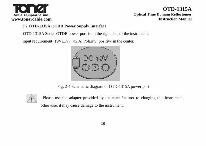
3.2 OTD-1315A OTDR Power Supply Interface
OTD-1315A Series OTDR power port is on the right side of the instrument.
Input requirement: 19V±1V,≥2 A, Polarity: positive in the center.
Fig. 2-4 Schematic diagram of OTD-1315A power port
Please use the adapter provided by the manufacturer to charging this instrument,
otherwise, it may cause damage to the instrument.
17
www.tonercable.com
OTD-1315A Optical Time Domain Reflectomer
Instruction Manual
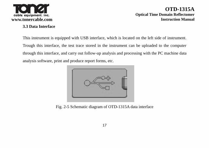
3.3 Data Interface
This instrument is equipped with USB interface, which is located on the left side of instrument.
Trough this interface, the test trace stored in the instrument can be uploaded to the computer
through this interface, and carry out follow-up analysis and processing with the PC machine data
analysis software, print and produce report forms, etc.
Fig. 2-5 Schematic diagram of OTD-1315A data interface
18
www.tonercable.com
OTD-1315A Optical Time Domain Reflectomer
Instruction Manual
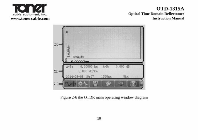
4. Operation interface and button of OTD-1315A Series OTDR
The operation interface of OT-1315A Series OTDR is very simple, which is mainly divided into
operation window area and menu display area. When the instrument is started to enter the
application interface, the interface appearing on the display screen is the main operating window,
as shown in Fig. 2-6. The main operating window includes all six main operating menu bars of
OTDR and each menu bar contains different sub-windows. Through these operation buttons,
start the different sub-windows to realize the corresponding functions. (Details see the operation
method).
19
www.tonercable.com
OTD-1315A Optical Time Domain Reflectomer
Instruction Manual
Figure 2-6 the OTDR main operating window diagram

20
www.tonercable.com
OTD-1315A Optical Time Domain Reflectomer
Instruction Manual
The description of notes is as follows:
(1) the OTDR function menu area, where the yellow background indicates the current menu selection location.
(2) sub-operations area of the test parameters and test results. This area can be changed according to different
selections of menu.
(3) the main instrument display interface area.
4.1 Menu structure and functional description
OTD-1315A Series OTDR has the simplest and quick operation way in the industry. The whole main user
interface contains only 6 menu options. Through the optimized operating mode, it can conform to the user’s
daily habits; besides, the unique key plus touch screen function operating mode of the similar products in the
industry can facilitate the operation and eliminate the tedious process of frequent movement of cursor.
21
www.tonercable.com
OTD-1315A Optical Time Domain Reflectomer
Instruction Manual
22
www.tonercable.com
OTD-1315A Optical Time Domain Reflectomer
Instruction Manual
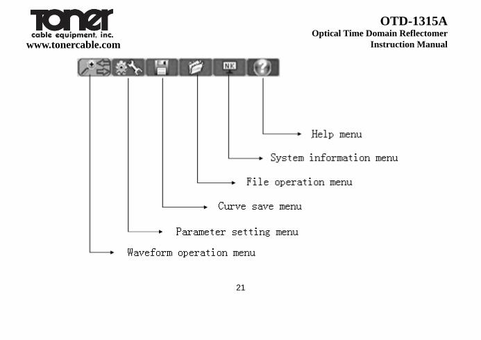
Fig. 2-7 Schematic diagram of main window menu bar
Fig. 2-7 shows the schematic diagram of the six main menu of OTD-1315A Series OTDR,
which respectively “waveform operation”, “parameter setting”, “curve save”, “file operation”,
“system information”, “help” from left to the right.
23
www.tonercable.com
OTD-1315A Optical Time Domain Reflectomer
Instruction Manual
4.2 Description of the OTDR button functions

24
www.tonercable.com
OTD-1315A Optical Time Domain Reflectomer
Instruction Manual
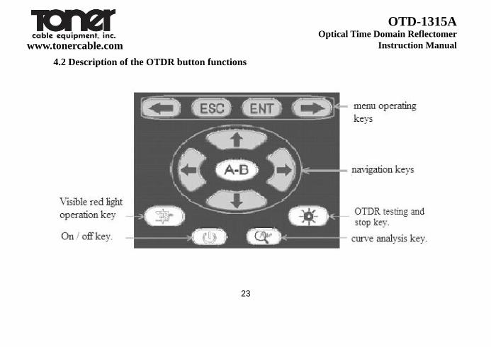
Fig. 2-8 Schematic diagram of OTD-1315A OTDR keys
The functions of various buttons on the keys are as follows:
The four keys in the “menu operating key” marked in the above figure 2-8 are mainly for the
menu operation, to realize the menu selection, entry and exit, etc. of which:
: Left movement in the OTDR operation menu.
:Right movement in the OTDR operation menu.
: The menu of the currently selected cursor. If this menu contains subordinate menu
interface, then when pressing this key, the corresponding sub-interface will pop up.
:The menu of exit the current cursor, or the corresponding sub-interface.
The five keys “navigation keys” marked in Fig. 2-8 are mainly to realize the movement,
switching of cursor and the parameter selection and modification in sub-interface, of which:
25
www.tonercable.com
OTD-1315A Optical Time Domain Reflectomer
Instruction Manual
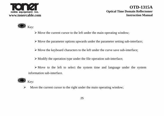
Key:
Move the current cursor to the left under the main operating window;
Move the parameter options upwards under the parameter setting sub-interface;
Move the keyboard characters to the left under the curve save sub-interface;
Modify the operation type under the file operation sub-interface;
Move to the left to select the system time and language under the system
information sub-interface.
Key:
Move the current cursor to the right under the main operating window;

26
www.tonercable.com
OTD-1315A Optical Time Domain Reflectomer
Instruction Manual
Move the parameter options downwards under the parameter setting sub-interface;
Move the keyboard characters to the right under the curve save sub-interface;
Modify the file operation path under the file operation sub-interface;
Move to the right to select the system time and language under the system information
sub-interface.
Key:
Move the waveform upwards under the waveform movement menu;
Expand the waveform horizontally under the waveform horizontal expansion /
compression menu;
27
www.tonercable.com
OTD-1315A Optical Time Domain Reflectomer
Instruction Manual
Expand the waveform vertically under the waveform vertical expansion /
compression menu;
Modify the value of the parameters under the parameter setting sub-interface;
Modify the path under the curve save sub-interface;
Select the file to be operated under the file operation sub-interface;
Modify the value of the item where the cursor is under the system information
sub-interface;
Use to page up under the help information interface.
28
www.tonercable.com
OTD-1315A Optical Time Domain Reflectomer
Instruction Manual
Key:
Move the waveform downwards under the waveform movement menu;
Compress the waveform horizontally under the waveform horizontal
expansion / compression menu;
Compress the waveform vertically under the waveform vertical expansion /
compression menu;
Modify the value of the parameters under the parameter setting
sub-interface;
Modify the path under the curve save sub-interface;
Select the file to be operated under the file operation sub-interface;

29
www.tonercable.com
OTD-1315A Optical Time Domain Reflectomer
Instruction Manual
Modify the value of the item where the cursor is under the system
information sub-interface;
Use to page down under the help information interface.
Key:
Switch the cursors A and B under the waveform operating menu;
Confirm and exit the parameter setting sub-interface and this function is
equivalent to the key.
Key: OTDR testing and stop key.
When the OTDR operating interface displays as the main operating window, press down this
button to start the OTDR module to test the optical fiber and display the test curve in the main
30
www.tonercable.com
OTD-1315A Optical Time Domain Reflectomer
Instruction Manual
operating window. The test is divided into automatic test, real-time test and average test. The test
way can be set in the OTDR parameter setting window.
Key: curve analysis key.
Press down this key under the OTDR operation interface to analyze the displayed curve. Give
the analysis results under the curve. If no curve or the curve has no the event to meet the
condition, it is a null operation.
Key: Visible red light operation key
When the OTDR is in the non-test status, press and hold this key for about 2 seconds, and this
light is on, indicating that the visual fault positioning function is started under the DC mode; at
this time, press the key once again, the key light flickers, and the visual fault positioning
function working way changes to the flickering way; and press the key once again, the visual
31
www.tonercable.com
OTD-1315A Optical Time Domain Reflectomer
Instruction Manual
fault positioning function is closed and the light of the key is off.
Key: On / off key.
When the instrument is under the off state, press this key about 1s, the instrument is started to
enter the OTDR operating interface and display the main operation window. When the
instrument is switched on, press and hold this button for about 1 second to switch off the
instrument.
4.3 Description of OTD-1315A Series OTDR test parameters and setting method
Correct setting the measurement parameters of the instrument is necessary for the accurate
measurement of the optical fibers. Therefore, prior to the use of the instrument, it is necessary to
set parameters as required. The test parameters of OTDR are mainly testing wavelength,
measurement range, pulse width, channels, refractive index, fiber optic correction coefficient
32
www.tonercable.com
OTD-1315A Optical Time Domain Reflectomer
Instruction Manual
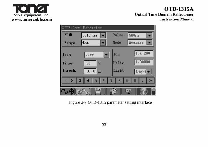
and event threshold value, etc..
In the main operating interface, move the cursor to the parameter setting menu through
the menu operating key or , then press the key , the parameter setting
interface will pop up.
33
www.tonercable.com
OTD-1315A Optical Time Domain Reflectomer
Instruction Manual
Figure 2-9 OTD-1315 parameter setting interface

34
www.tonercable.com
OTD-1315A Optical Time Domain Reflectomer
Instruction Manual
4.3.1 Description of parameters and setting method
WL(nm): to set the OTDR test wavelength.
Setting method: Under the parameter setting interface, move the cursor to the wavelength
option via the navigation key or , and press the key or to select
the wavelength value, or directly click on the touch screen wavelength window to select it,
and press the key to save the setting and exit the window.
■ Range (km): set the scope of the scan path. The range should be set according to the actual
length of the optical fiber. The predefined range should be greater than the length of the
measured optical fibers; usually it is more than twice of the length of the optical fibers to be
measured. Under the automatic test mode, it is not required to set by the users.
Setting method: Under the parameter setting interface, move the cursor to the option
35
www.tonercable.com
OTD-1315A Optical Time Domain Reflectomer
Instruction Manual
Range via the navigation key or , and press the key or to select the
value of the range, or directly click on the touch screen range window to select it, and press the
key to save the setting and exit the window.
Pulse (ns): Set the laser pulse width emitted from instrument. The selection of pulse width
will affect the dynamic range and resolution of the test curve. The large pulse width may
obtain a high dynamic range and test a long optical fiber, but the resolution is poor; the
small pulse width may have high resolution, but it can test a short distance. Users need to
make appropriate choice between the dynamic scope and blind spot. Under the automatic
test mode, users need not set them.
Setting method: Under the parameter setting interface, move the cursor to the option Pulse
Width via the navigation key or , and press the key or to select
the value of the range, or directly click on the touch screen range window to select it, and
36
www.tonercable.com
OTD-1315A Optical Time Domain Reflectomer
Instruction Manual
press the key to save the setting and exit the window.
■ Mode: Used to select the way of OTDR scan event. Select the “real-time test”, “average
test” and “automatic test”.
Of which, the “real-time test” is to perform real time scan on the test link and display the
test results, to perform dynamic monitoring on the links before and after connection
conveniently.
“Average test” is to accumulate the scan results for many times and perform average
processing, which can further enhance the testing curve quality and the testing precision.
“Automatic test” is an intelligent test way. Under this mode, the instrument can
automatically carryout the matching of the test conditions according to the test links; users
are not required to set the test conditions manually.
Setting method: Under the parameter setting interface, move the cursor to the option Test
37
www.tonercable.com
OTD-1315A Optical Time Domain Reflectomer
Instruction Manual
Method via the navigation key or , and press the key or to
select the test method, or directly click on the touch screen test method window to select it,
and press the key to save the setting and exit the window.
■ Item: Used to select the type of the OTDR test events; select the “average loss”,
“connection loss” and “reflection loss”.
Of which, the “average loss” is used to test the parameters such as total loss, spacing and
average loss between two points in the test link; through moving the location of the cursor
point, it can realize the measurement of any two points in the whole link.
“Connection loss” is used to test the connection point, welding points or the macro-bend
loss characteristics of the test link.
“Reflection loss” is used to conduct test on the losses of the reflection events in the link.
Setting method: Under the parameter setting interface, move the cursor to the option Test

38
www.tonercable.com
OTD-1315A Optical Time Domain Reflectomer
Instruction Manual
Item via the navigation key or , and press the key or to select
the test item, or directly click on the touch screen test item window to select it, and press
the key to save the setting and exit the window.
Times: under the modes of “average test” and “automatic test”, it is used to set the time
of them.
Setting method: Under the parameter setting interface, move the cursor to the option
Average Number of Times via the navigation key or , press the key or
to select the value, and press the key to save the setting and exit the window.
■ Thresh:
The event threshold for curve analysis. When the event point is discovered through curve
anlayis, the events that the loss between events is greater than the threshold value will be
39
www.tonercable.com
OTD-1315A Optical Time Domain Reflectomer
Instruction Manual
listed in the list of events, and those that the loss between events is less than the threshold
value will be ignored.
Setting method: Under the parameter setting interface, move the cursor to the option
Event Threshold via the navigation key or , or directly click on the touch
screen Event Threshold window and press the key or to select the threshold
value; and press the key to save the setting and exit the window.
■ IOR: Refractive index.
The refractive index of the optical fiber may affect the optical fiber transmission speed, so
the setting of refractive index will directly affect the accuracy of the measuring distance.
The refractive index of optical fibers is provided by the manufacturer.
Setting method: Under the parameter setting interface, move the cursor to the option
40
www.tonercable.com
OTD-1315A Optical Time Domain Reflectomer
Instruction Manual
Refractive Index via the navigation key or , or directly click on the touch
screen Refractive Index window and press the key or to select the set
refractive index; and press the key to save the setting and exit the window.
■ Helix:
The setting of the cable correction factor is to consider the change of the optical fiber length
and optical cable length after the optical fiber is changed to optical cable. This parameter
can be obtained from the optical cable manufacturer.
Setting method: Under the parameter setting interface, move the cursor to the option
Optical Cable Correction via the navigation key or , or directly click on the
touch screen Optical Cable Correction window and press the key or to select
the correction value; and press the key to save the setting and exit the window.

41
www.tonercable.com
OTD-1315A Optical Time Domain Reflectomer
Instruction Manual
■ Thresh:
The event threshold for curve analysis. When the event point is discovered through curve
anlayis, the events that the loss between events is greater than the threshold value will be
listed in the list of events, and those that the loss between events is less than the threshold
value will be ignored.
Setting method: Under the parameter setting interface, move the cursor to the option
Event Threshold via the navigation key or , or directly click on the touch
screen Event Threshold window and press the key or to select the threshold
value; and press the key to save the setting and exit the window.
■ Light: To set the light of LCD
Setting method: Under the parameter setting interface, move the cursor to the option
42
www.tonercable.com
OTD-1315A Optical Time Domain Reflectomer
Instruction Manual
Event Llight via the navigation key or , or directly click on the touch screen
Event Light window and press the key or to set the light of LCD.
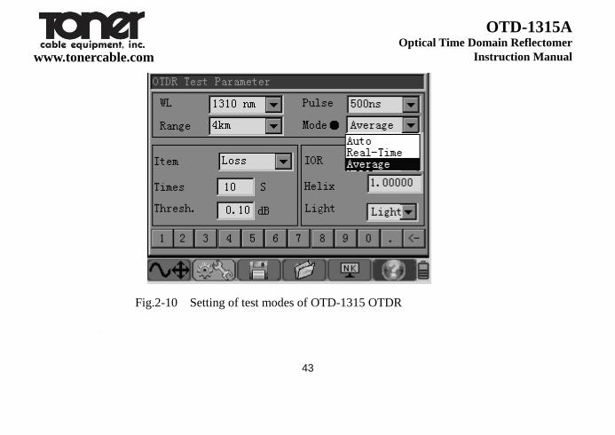
4.4 Description of testing ways of OTD-1315 series OTDR
There are 3 kinds of test modes of OTD-1315 OTDR: automatic test, real time test, average
test.
43
www.tonercable.com
OTD-1315A Optical Time Domain Reflectomer
Instruction Manual
Fig.2-10 Setting of test modes of OTD-1315 OTDR
44
www.tonercable.com
OTD-1315A Optical Time Domain Reflectomer
Instruction Manual
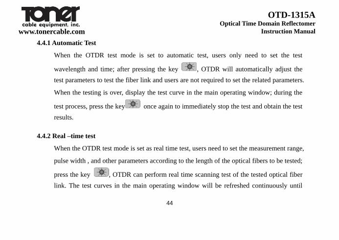
4.4.1 Automatic Test
When the OTDR test mode is set to automatic test, users only need to set the test
wavelength and time; after pressing the key , OTDR will automatically adjust the
test parameters to test the fiber link and users are not required to set the related parameters.
When the testing is over, display the test curve in the main operating window; during the
test process, press the key once again to immediately stop the test and obtain the test
results.
4.4.2 Real –time test
When the OTDR test mode is set as real time test, users need to set the measurement range,
pulse width , and other parameters according to the length of the optical fibers to be tested;
press the key , OTDR can perform real time scanning test of the tested optical fiber
link. The test curves in the main operating window will be refreshed continuously until

45
www.tonercable.com
OTD-1315A Optical Time Domain Reflectomer
Instruction Manual
pressing the key again, and then OTDR will stop testing.
4.4.3 Average test
When the OTDR test mode is set to the average test, users need to set the range, pulse
width, and other parameter according to the length of the tested optical fibers; press down
the key, OTDR can perform average test on the the tested optical fiber link
according to the set test parameters and the test curves in the main operating window will
be subject to average processing until the average number of times displayed ih the
interface is equal to the set one, OTDR stops the testing. In the average test process, press
down the key again, OTDR will immediately stop testing.
46
www.tonercable.com
OTD-1315A Optical Time Domain Reflectomer
Instruction Manual
4.5 Description of test items of OTD-1315A series OTDR
The test items of OTD-1315A OTDR include average loss, connection loss and reflection loss.

47
www.tonercable.com
OTD-1315A Optical Time Domain Reflectomer
Instruction Manual
Fig. 2-11 Setting of test methods of OTD-1315A OTDR
48
www.tonercable.com
OTD-1315A Optical Time Domain Reflectomer
Instruction Manual
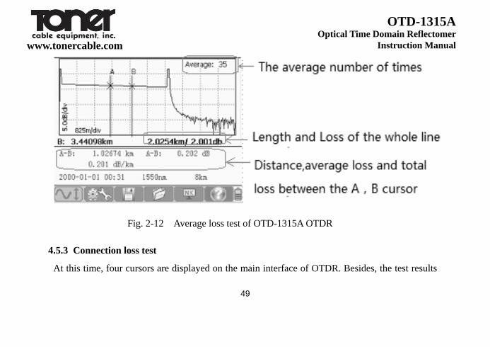
4.5.1 Average loss test
At this time, OTDR can perform test on the distance between cursor A and cursor B, the
loss between them and the average loss of the optical fiber segment where cursors A and B
are located. Through the navigation key, the cursors A and B can be switched and the
positions of them can be modified, so that customers can observe the detailed
characteristics of each fiber link distance.
49
www.tonercable.com
OTD-1315A Optical Time Domain Reflectomer
Instruction Manual
Fig. 2-12 Average loss test of OTD-1315A OTDR
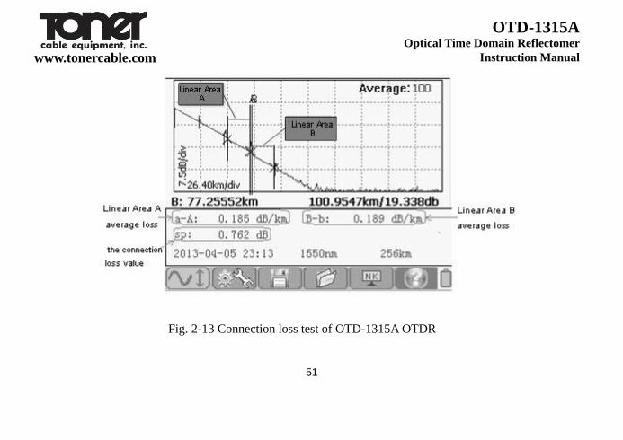
4.5.3 Connection loss test
At this time, four cursors are displayed on the main interface of OTDR. Besides, the test results

50
www.tonercable.com
OTD-1315A Optical Time Domain Reflectomer
Instruction Manual
show the connection loss of the connection points where the cursor A is located and the average
loss of the optical fiber segments before and after the connection points.
As shown in Figure 2-13, move the cursors A and B before and after the connection events to be
tested and close to the two sides of the event respectively. Move the small cursor at the front of
cursor A to the far end of the previous segment of linear area of the event to be tested (linear area
A) and move the small cursor at the back of the cursor B to the far end of the following segment
of linear area of the event to be tested (linear area B), at this time, read the connection loss value
of the connection event through SP location.
51
www.tonercable.com
OTD-1315A Optical Time Domain Reflectomer
Instruction Manual
Fig. 2-13 Connection loss test of OTD-1315A OTDR

52
www.tonercable.com
OTD-1315A Optical Time Domain Reflectomer
Instruction Manual
4.5.3 Reflection Loss Test
At this time, two cursors A and B occur in the main interface of OTDR. When testing the
reflection event loss, move the cursor A to the front of the reflection event and close to the
jumping edge, and then move the cursor B to the top of the reflection event. Read the reflection
loss value of the reflection event through the Ref position.

53
www.tonercable.com
OTD-1315A Optical Time Domain Reflectomer
Instruction Manual
Fig. 2-14 Reflection loss test of OTD-1315A OTDR
54
www.tonercable.com
OTD-1315A Optical Time Domain Reflectomer
Instruction Manual
5. Description of application method of OTD-1315A series OTDR
5.1 Automatic analysis of the waveform and check the list of events
After the OTDR stops the testing and the test curve is obtained, press down the key ,
conduct analysis on the obtained curve, and perform screening and positioning of the event
points according to the set event threshold value to obtain the length, loss, average loss and
other information of the optical fiber links. Besides, display the event point information at
the event list column in the main operating window.
Press the key or the key can check the information of all event points in the
list of events.

55
www.tonercable.com
OTD-1315A Optical Time Domain Reflectomer
Instruction Manual
Fig. 2-15 Analysis results of OTD-1315A OTDR
In the sub-operating window of event list:
: indicate that this event is a non-reflective event point, generally the event caused by

56
www.tonercable.com
OTD-1315A Optical Time Domain Reflectomer
Instruction Manual
splices, splitters, fiber bending or extrusion, etc..
: indicate that this event is a reflective event point, generally the event caused by
movable connector of the optic fiber link.
:indicate that this event point is the end of optical fiber.
5.2 Move, switch the cursor and set the mark point
Set the position of the mark points through moving the position of the cursor. Move the
current activated cursor to the left and right via the navigation key or . When
continuously hold the key or and moving 10 data points, the active cursor will
move rapidly and move 10 data points each time. Release the key or , then the
active cursor will stop moving; or directly click on the touch screen and move the currently
activated cursor to the appropriate touch point. Press the key of the navigation keys to
switch the cursor points.
57
www.tonercable.com
OTD-1315A Optical Time Domain Reflectomer
Instruction Manual
5.3 Zooming and shift of waveform curve
To facilitate users to carry out manual analysis on the tested curve, when the test of
OTD-1315A Series OTDR is over, the menu key is placed on horizontal zoom-in and
zoom-out of the curve operating menu in default, and at this time, just directly press
the navigation keys and to realize the horizontal zoom-in and zoom-out of the
test curve in the center of currently activated cursor. At this time, the key or
in the navigation keys can be shifted left or right to move the cursor.
When continuously pressing the key in the menu operating keys, or clicking on the
curve operating menu in the touch screen, at this time, this menu can realize the alternative
switching among , and .
58
6. Visual red light fault positioning
With the built-in high-power visual red light fault positioning function, OTD-1315AOTDR
can discover the breakpoint of the short-distance optical fiber link or the position of a large
loss point very conveniently and intuitively. Combing with OTDR function, it can realize the
seamless monitoring of the link test so that the maintenance personnel can discover the
problems of the links timely and take measures to save the test time.
There are two output modes for the visible red light of OTD-1315s OTDR:
DC mode;
AC mode.
In the OTDR test main interface, when the OTDR is under the non-test status, press and hold
the key for about 2s, the light is on, indicating that the visual fault positioning function
is started and the working mode is DC mode; press this key once again, the light of the key

59
www.tonercable.com
OTD-1315A Optical Time Domain Reflectomer
Instruction Manual
flickers and the working mode of the visual fault positioning function is changed to AC mode;
press this key again, the visual fault positioning function is closed and the light of the key is
off. If pressing the key to start the OTDR function before starting the visual red light
fault positioning function, then the visual red light fault positioning function will be
automatically closed and switched to the OTDR test function.
7. File management operation
The OTD-1315A Series OTDR file management operations are described as follows, mainly
including file save, reading, copy, deletion, etc..
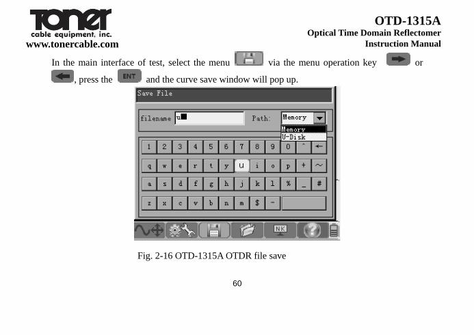
7.1 Save the waveform files
When the automatic measurement or manual measurement is over, save the measurement
curve. The contents of the saved curve are the curve and related information of curve.
60
www.tonercable.com
OTD-1315A Optical Time Domain Reflectomer
Instruction Manual
In the main interface of test, select the menu via the menu operation key or
, press the and the curve save window will pop up.
Fig. 2-16 OTD-1315A OTDR file save
61
www.tonercable.com
OTD-1315A Optical Time Domain Reflectomer
Instruction Manual
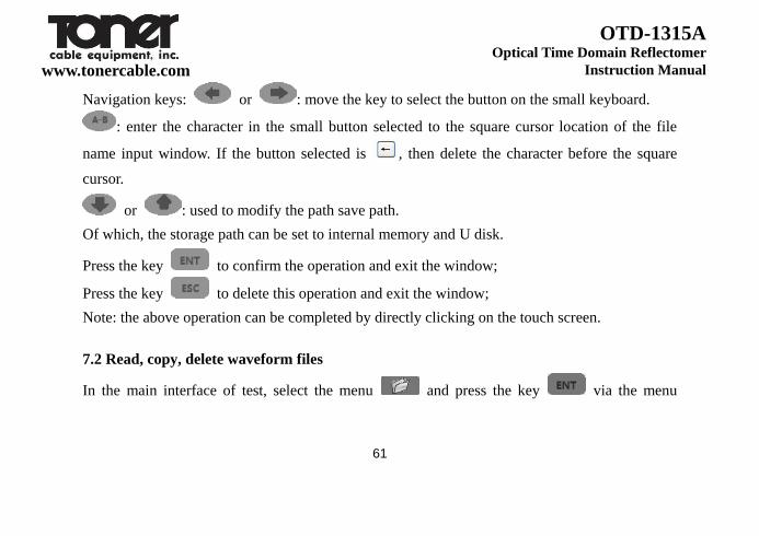
Navigation keys: or : move the key to select the button on the small keyboard.
: enter the character in the small button selected to the square cursor location of the file
name input window. If the button selected is , then delete the character before the square
cursor.
or : used to modify the path save path.
Of which, the storage path can be set to internal memory and U disk.
Press the key to confirm the operation and exit the window;
Press the key to delete this operation and exit the window;
Note: the above operation can be completed by directly clicking on the touch screen.
7.2 Read, copy, delete waveform files
In the main interface of test, select the menu and press the key via the menu
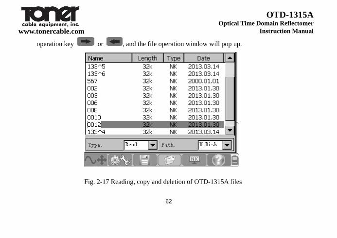
62
www.tonercable.com
OTD-1315A Optical Time Domain Reflectomer
Instruction Manual
operation key or , and the file operation window will pop up.
Fig. 2-17 Reading, copy and deletion of OTD-1315A files

63
www.tonercable.com
OTD-1315A Optical Time Domain Reflectomer
Instruction Manual
Select the operation type via the navigation key . There are 3 types: read, copy and delete;
Of which, when selecting the copy way and the read path is internal memory, copy the memory
files to the U disk;
When the read path is U disk, copy the U disk files to the internal memory.
key: select the operation path, which can be divided into two types: internal memory and
U disk.
or key : used to select the operation files.
key : used to select all of the operation files.
Press the key to confirm the operation and exit the window;
Press the key to delete this operation and exit the window;
Note: the above operation can be completed by directly clicking on the touch screen.
64
www.tonercable.com
OTD-1315A Optical Time Domain Reflectomer
Instruction Manual
8. Set the system time and language, screen brightness and view the system information
In the main test interface, select the menu via the menu operating key or ,
press the key and the system information setting window will pop up.
65
www.tonercable.com
OTD-1315A Optical Time Domain Reflectomer
Instruction Manual
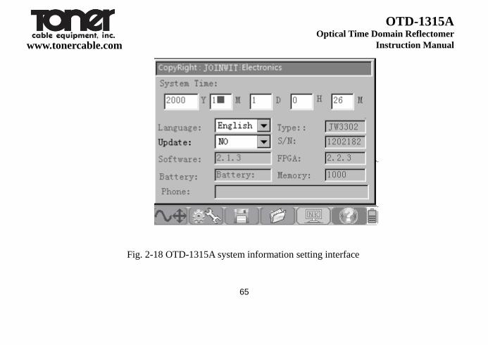
Fig. 2-18 OTD-1315A system information setting interface
66
www.tonercable.com
OTD-1315A Optical Time Domain Reflectomer
Instruction Manual
The navigation key or :move the cursor ■ to select the operation item;
or key: used to modify the parameters of the operation item.
Press the key to confirm the operation and exit the window;
Press the key to delete the operation and exit the window;
9. View help information
In the main test interface, select the menu via the menu operating key or
, press the key and the help information window will pop up.
67
www.tonercable.com
OTD-1315A Optical Time Domain Reflectomer
Instruction Manual
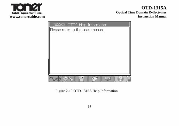
Figure 2-19 OTD-1315A Help Information
68
www.tonercable.com
OTD-1315A Optical Time Domain Reflectomer
Instruction Manual
Navigation key or : used to page down, page up.
Press the key and exit the window.
Chapter 3 Maintenance and Troubleshooting
69
Chapter 3 Maintenance and Troubleshooting
3.1 Routine operation and maintenance
3.1.1 Cleaning of connector
The optical output interface of OTD-1315A Series OTDR is a universal optical interface that can
be replaced. During the service process, it is necessary to keep the face clean. When the normal
curve cannot be tested by the instrument or the test results are inaccurate, clean the connector
firstly.
Make sure that cleaning is carried out when the OTDR and the visual red fault positioning
function are stopped. Unscrew the output interface and wipe the connection face with a special
paper towel or cotton swab dipped by alcohol.
Chapter 3 Maintenance and Troubleshooting
70
Besides, when the instrument is not in use, cover the dust cap and keep it clean.
3.1.2 Routine maintenance of internal battery
The battery inside the OTD-1315A Series OTDR is a dedicated lithium battery. When first use of
this instrument, supply electricity through the battery; when the battery is completely discharged,
charge the battery. The first time of charging time should be more than 8 hours. For your safety
use, multiple protection measures on the battery voltage, charge current, charge temperature, etc
have been set in the internal charging circuit. The battery charging temperature range is 0℃~
50℃. When the ambient temperature is too high, the charge will be automatically stopped. When
the instrument is not in use for a long time, charge the battery on regular basis. It is
recommended to charge the battery once every 2-3 months to ensure the best performance of the
battery.

Chapter 3 Maintenance and Troubleshooting
71
3.1.3 Cleaning of instrument screen and calibration
The display of OTD-1315A series OTDR is a 3.5-inch color LCD with touch screen. Do not
click on the LCD with a sharp object when in use, otherwise, it may cause damage to the LCD
screen.
Clean the LCD screen with a soft abric. Do not clean the LCD screen with organic solvents,
otherwise, it may cause damage to the LCD screen.
3.1.4 Calibration
During normal use of the instrument, it is recommended that the OTD-1315A Series OTDR
should be calibrated once every two years. For the details about the calibration, please contact
the instrument supplier.

Chapter 3 Maintenance and Troubleshooting
72
3.2 Faults and solutions
Table 3-1 Faults and solutions
Faults Causes Solutions
Instrument does not
start properly
No electricity of the battery
Charge the battery and observe the light of the
on/off key; if the light is red, continue to charge;
otherwise, contact the supplier.
Chapter 3 Maintenance and Troubleshooting
73
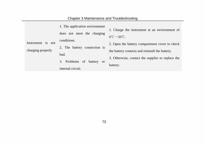
Instrument is not
charging properly
1. The application environment
does not meet the charging
conditions.
2. The battery connection is
bad.
3. Problems of battery or
internal circuit.
1. Charge the instrument at an environment of
0℃~50℃.
2. Open the battery compartment cover to check
the battery contacts and reinstall the battery.
3. Otherwise, contact the supplier to replace the
battery.
Chapter 3 Maintenance and Troubleshooting
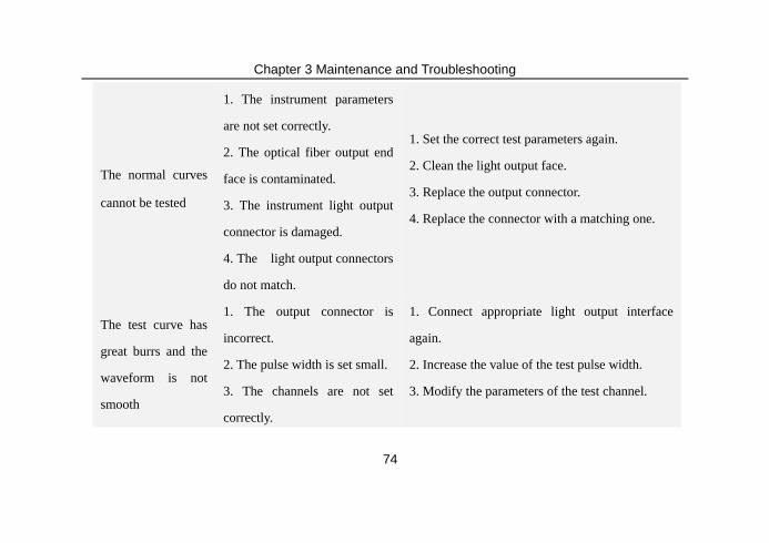
74
The normal curves
cannot be tested
1. The instrument parameters
are not set correctly.
2. The optical fiber output end
face is contaminated.
3. The instrument light output
connector is damaged.
4. The light output connectors
do not match.
1. Set the correct test parameters again.
2. Clean the light output face.
3. Replace the output connector.
4. Replace the connector with a matching one.
The test curve has
great burrs and the
waveform is not
smooth
1. The output connector is
incorrect.
2. The pulse width is set small.
3. The channels are not set
correctly.
1. Connect appropriate light output interface
again.
2. Increase the value of the test pulse width.
3. Modify the parameters of the test channel.
Chapter 3 Maintenance and Troubleshooting
75
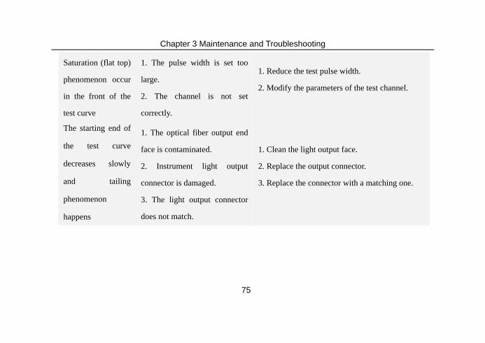
Saturation (flat top)
phenomenon occur
in the front of the
test curve
1. The pulse width is set too
large.
2. The channel is not set
correctly.
1. Reduce the test pulse width.
2. Modify the parameters of the test channel.
The starting end of
the test curve
decreases slowly
and tailing
phenomenon
happens
1. The optical fiber output end
face is contaminated.
2. Instrument light output
connector is damaged.
3. The light output connector
does not match.
1. Clean the light output face.
2. Replace the output connector.
3. Replace the connector with a matching one.

Chapter 3 Maintenance and Troubleshooting
76
The reflection peak
at the end of the
optical fiber cannot
be identified
1. The range is set too small.
2. The pulse width is set too
small.
1. Increase the test range value.
2. Increase the pulse width.
Mistaken reporting
of the curve
analysis
1. The test curve has poor
quality.
2. The event threshold is set
too small.
1. Increase the pulse width.
2. Increase the event threshold value.
Chapter 3 Maintenance and Troubleshooting
77
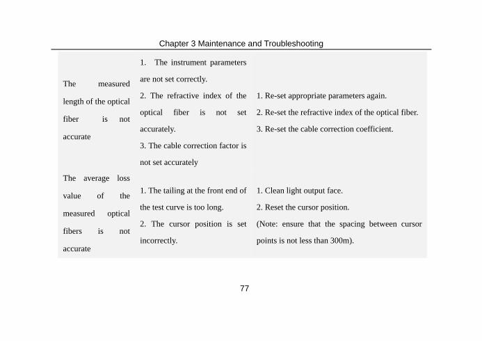
The measured
length of the optical
fiber is not
accurate
1. The instrument parameters
are not set correctly.
2. The refractive index of the
optical fiber is not set
accurately.
3. The cable correction factor is
not set accurately
1. Re-set appropriate parameters again.
2. Re-set the refractive index of the optical fiber.
3. Re-set the cable correction coefficient.
The average loss
value of the
measured optical
fibers is not
accurate
1. The tailing at the front end of
the test curve is too long.
2. The cursor position is set
incorrectly.
1. Clean light output face.
2. Reset the cursor position.
(Note: ensure that the spacing between cursor
points is not less than 300m).
Chapter 3 Maintenance and Troubleshooting
78
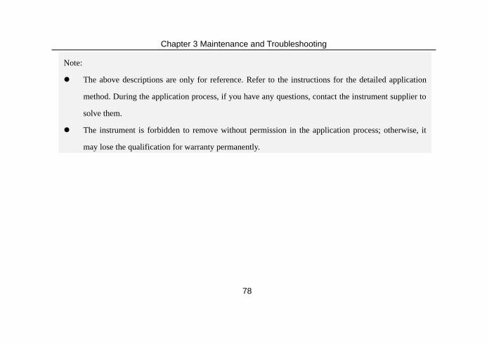
Note:
The above descriptions are only for reference. Refer to the instructions for the detailed application
method. During the application process, if you have any questions, contact the instrument supplier to
solve them.
The instrument is forbidden to remove without permission in the application process; otherwise, it
may lose the qualification for warranty permanently.
79
Chapter 4 Technical parameters and purchase information
4.1 Technical parameters
4.1.1 Main features of OTD-1315A Series OTDR
Novel and beautiful appearance and structure design;
Special protection design of shell, durable and able to work under bad environment;
Simplest operating interface, shortcut key operation, easy to use;
Dual operation of touch screen and keys;
Short event blind zone, test 5 m fiber jumper easily; Have a multiple kinds of test
80
modes such as automatic test, manual test and blind zone test, etc..
Light detection and alarm are provided in the line, to avoid signal light from damage
the instrument in the tested optical fiber;
Built-in high-power visual red light fault positioning function;
The USB interface functions can quickly realize the file transfer and report form
preparation;
The universal light output connector is easy to replace, which is able to realize e a
Smart battery electric quantity indication and low –voltage alarm function;
10-hour long time of duration, particularly suitable for the field construction
81
application for a long time;
The multi-wavelength and dynamic range selection can satisfy customer’s high higher
cost performance demands to the greatest extent;
The highly intelligent analysis software can accurately identify the fault splices,
connectors and even macro-bending;
Language: multiple choices of languages, such as Chinese, English, etc, which can be
customized according to customer’s requirements.
4.1.2 Main functions of OTD-1315A Series OTDR
Test the distance from any point of the optical fiber link to OTDR output end (origin of

82
test);
Test the distance between any two points of the optical fiber link;
Test and display the loss of any two points in the optical fiber link and fiber
attenuation constant;
Test and display the connection loss of the connection points in the optical fiber link;
Test the value of the reflection loss in the fiber link;
The automatic search function of connection point;
Test the waveform storage function;
File copy function: copy the data files stored in this machine directly to the U disk;
Electric quantity indication of smart battery;
83
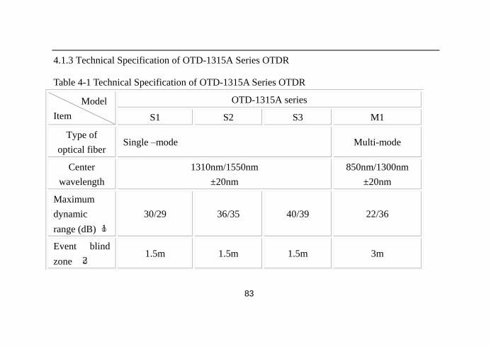
4.1.3 Technical Specification of OTD-1315A Series OTDR
Table 4-1 Technical Specification of OTD-1315A Series OTDR
Model
Item
OTD-1315A series
S1 S2 S3 M1
Type of
optical fiber Single –mode Multi-mode
Center
wavelength
1310nm/1550nm
±20nm
850nm/1300nm
±20nm
Maximum
dynamic
range (dB) ○1
30/29 36/35 40/39 22/36
Event blind
zone ○2 1.5m 1.5m 1.5m 3m
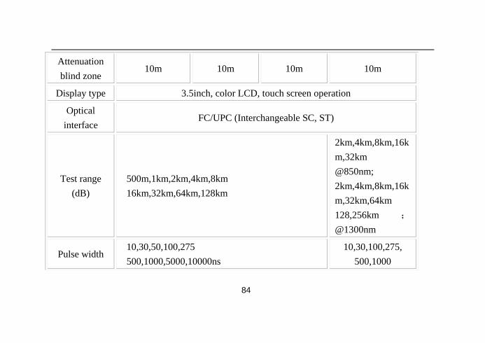
84
Attenuation
blind zone 10m 10m 10m 10m
Display type 3.5inch, color LCD, touch screen operation
Optical
interface FC/UPC (Interchangeable SC, ST)
Test range
(dB)
500m,1km,2km,4km,8km
16km,32km,64km,128km
2km,4km,8km,16k
m,32km
@850nm;
2km,4km,8km,16k
m,32km,64km
128,256km ;
@1300nm
Pulse width 10,30,50,100,275
500,1000,5000,10000ns
10,30,100,275,
500,1000
85
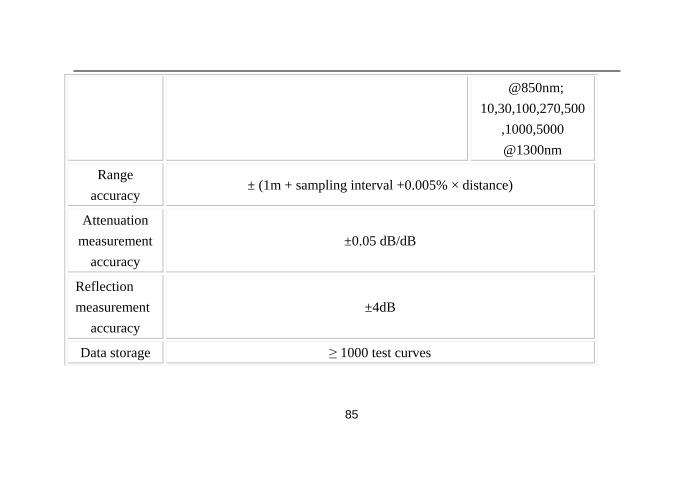
@850nm;
10,30,100,270,500
,1000,5000
@1300nm
Range
accuracy ± (1m + sampling interval +0.005% × distance)
Attenuation
measurement
accuracy
±0.05 dB/dB
Reflection
measurement
accuracy
±4dB
Data storage ≥ 1000 test curves
86
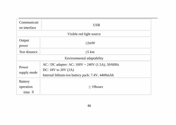
Communicati
on interface USB
Visible red light source
Output
power ≥2mW
Test distance ≥5 km
Environmental adaptability
Power
supply mode
AC / DC adapter: AC: 100V ~ 240V (1.5A), 50/60Hz
DC: 18V to 20V (2A)
Internal lithium-ion battery pack: 7.4V, 4400mAh
Battery
operation
time ○3
≥ 10hours
87
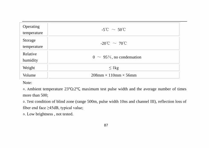
Operating
temperature -5℃ ~ 50℃
Storage
temperature -20℃ ~ 70℃
Relative
humidity 0 ~ 95%, no condensation
Weight ≤ 1kg
Volume 208mm × 110mm × 56mm
Note:
○1 . Ambient temperature 23℃±2℃, maximum test pulse width and the average number of times
more than 500;
○2 . Test condition of blind zone (range 500m, pulse width 10ns and channel III), reflection loss of
fiber end face ≥45dB, typical value;
○3 . Low brightness , not tested.
88
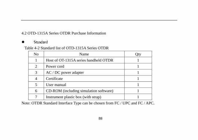
4.2 OTD-1315A Series OTDR Purchase Information
rd
Table 4-2 Standard list of OTD-1315A Series OTDR
No Name Qty
1 Host of OT-1315A series handheld OTDR 1
2 Power cord 1
3 AC / DC power adapter 1
4 Certificate 1
5 User manual 1
6 CD-ROM (including simulation software) 1
7 Instrument plastic box (with strap) 1
Note: OTDR Standard Interface Type can be chosen from FC / UPC and FC / APC.