OSI(Open System Interconnection) model
49
TOPIC: OSI MODEL Submitted by: Shahreen Gul (1544-BSEE-FET-F11) Namra Afzal (1528-BSEE-FET-F11) Irum Fatima (1545-BSEE-FET-F11)
-
Upload
namra-afzal -
Category
Engineering
-
view
190 -
download
3
Transcript of OSI(Open System Interconnection) model

TOPIC:
OSI MODEL
Submitted by:
Shahreen Gul (1544-BSEE-FET-F11) Namra Afzal (1528-BSEE-FET-F11) Irum Fatima (1545-BSEE-FET-F11)
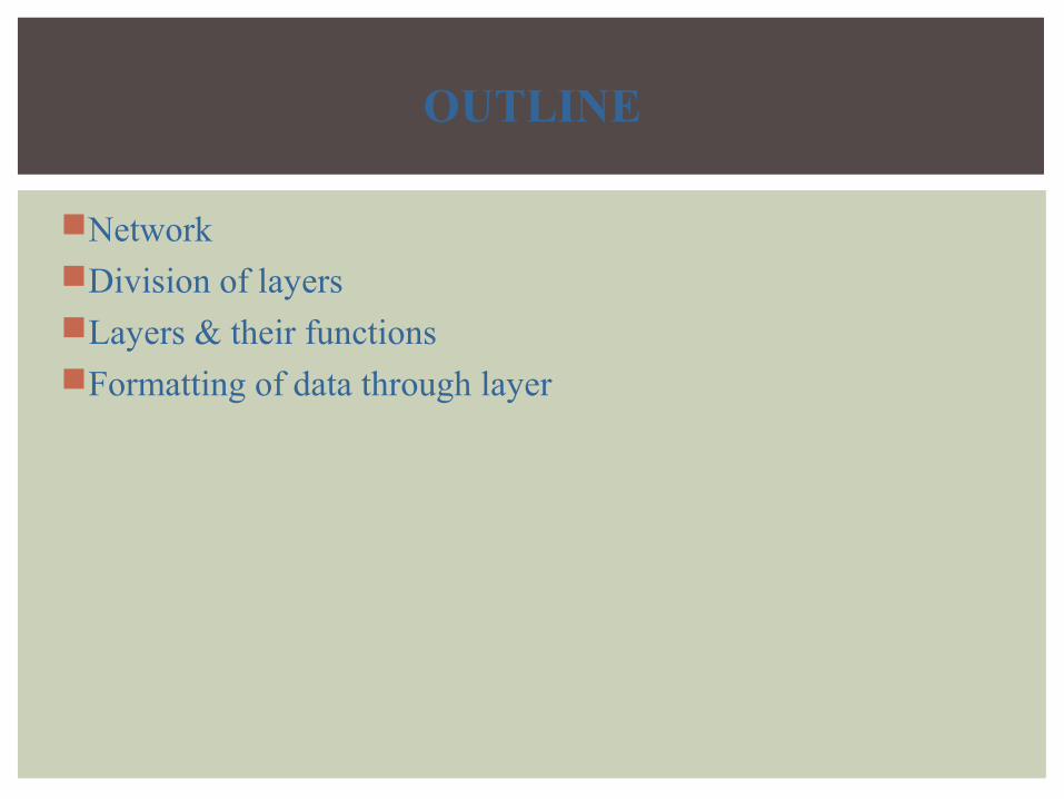
OUTLINE
Network Division of layersLayers & their functionsFormatting of data through layer
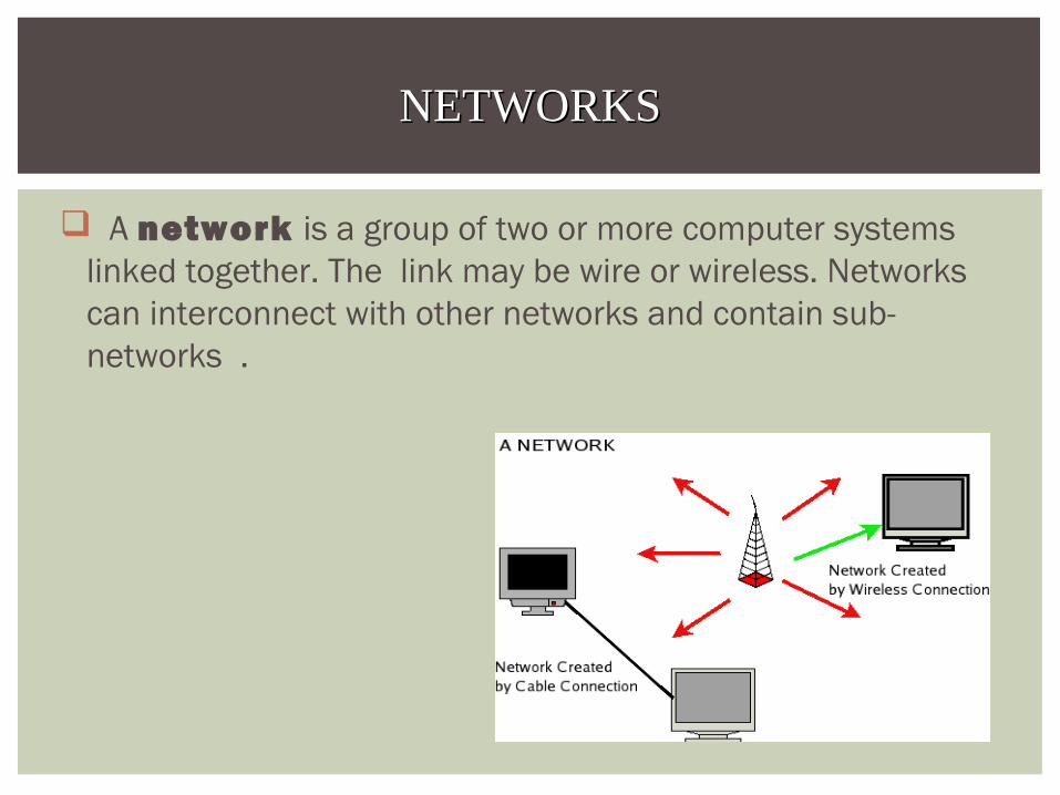
A network is a group of two or more computer systems linked together. The link may be wire or wireless. Networks can interconnect with other networks and contain sub-networks .
NETWORKSNETWORKS
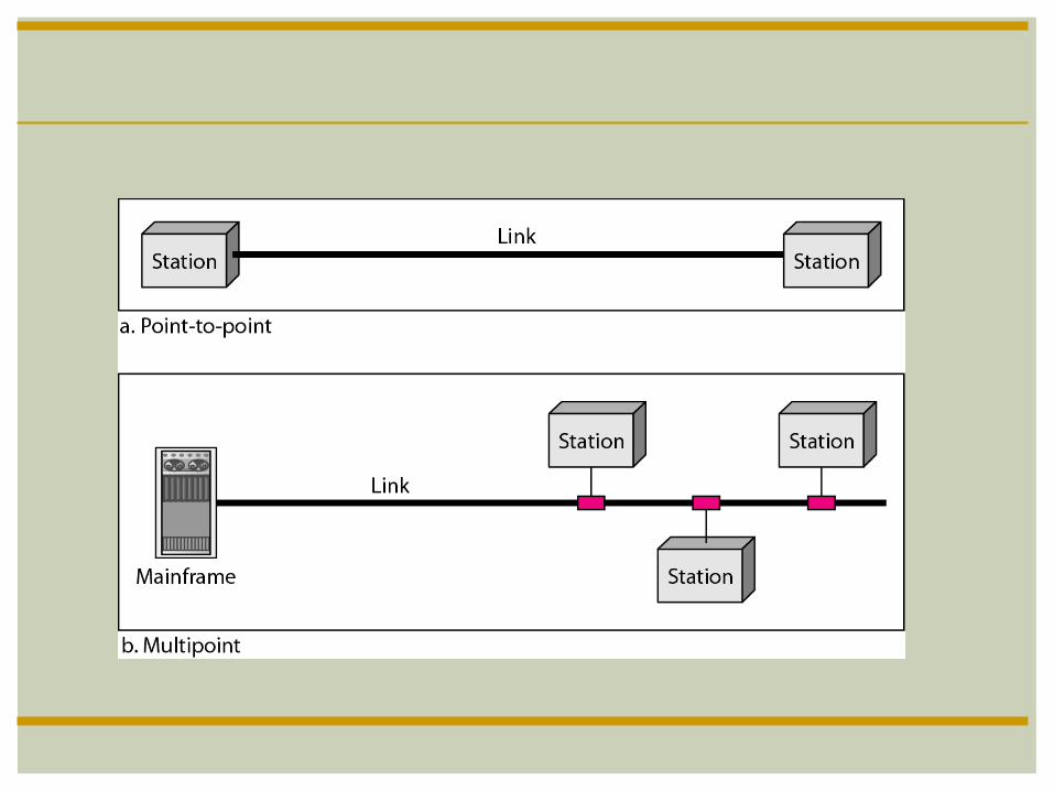

DATA COMMUNICATION
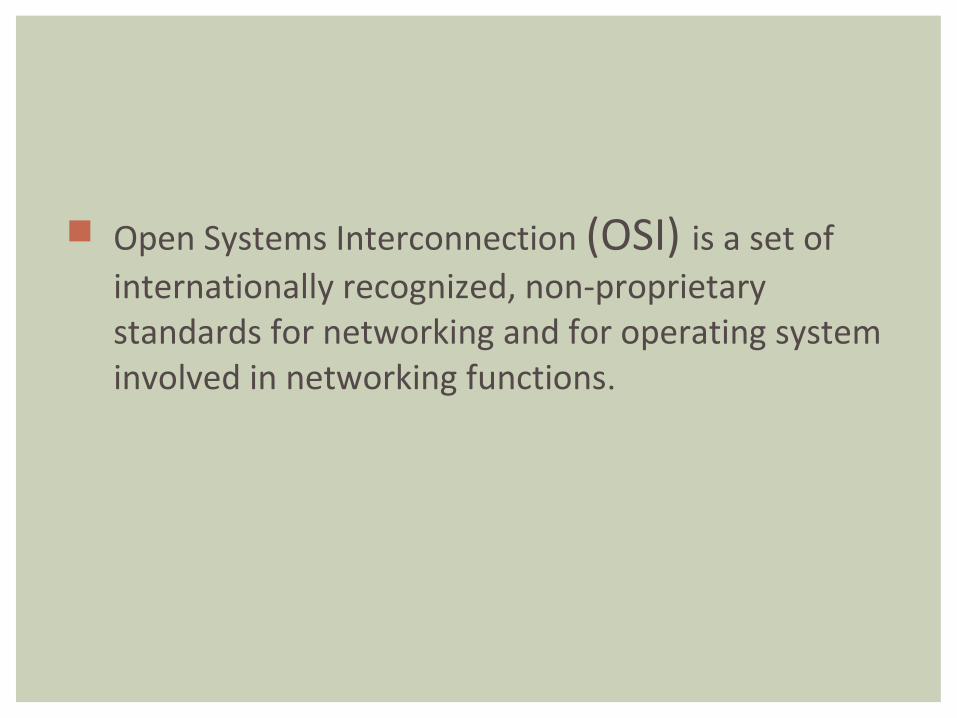
Open Systems Interconnection (OSI) is a set of internationally recognized, non-proprietary standards for networking and for operating system involved in networking functions.
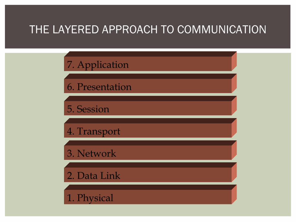
THE LAYERED APPROACH TO COMMUNICATION
7. Application
6. Presentation
5. Session
4. Transport
3. Network
2. Data Link
1. Physical
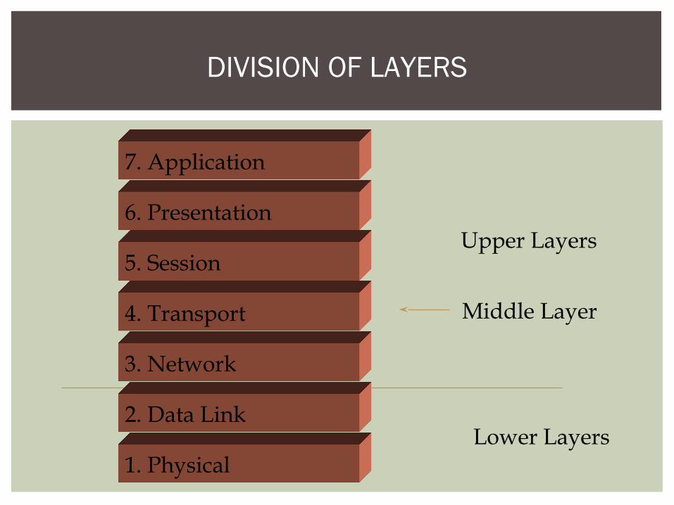
DIVISION OF LAYERS
Upper Layers
Lower Layers
Middle Layer
7. Application
6. Presentation
5. Session
4. Transport
3. Network
2. Data Link
1. Physical
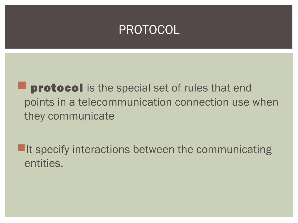
protocol is the special set of rules that end points in a telecommunication connection use when they communicate
It specify interactions between the communicating entities.
PROTOCOL


Each layer deals with one aspect of networking Layer 1 deals with the communication media
Each layer communicates with the adjacent layers In both directions Ex: Network layer communicates with:
Transport layer Data Link layer
Each layer formats the data packet Ex: Adds or deletes addresses
THE FUNCTION OF A LAYER
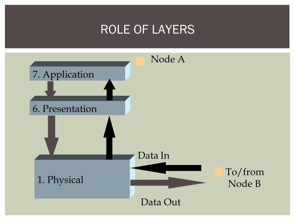
ROLE OF LAYERS
7. Application
6. Presentation
1. Physical
Node A
Data Out
Data In
To/from Node B
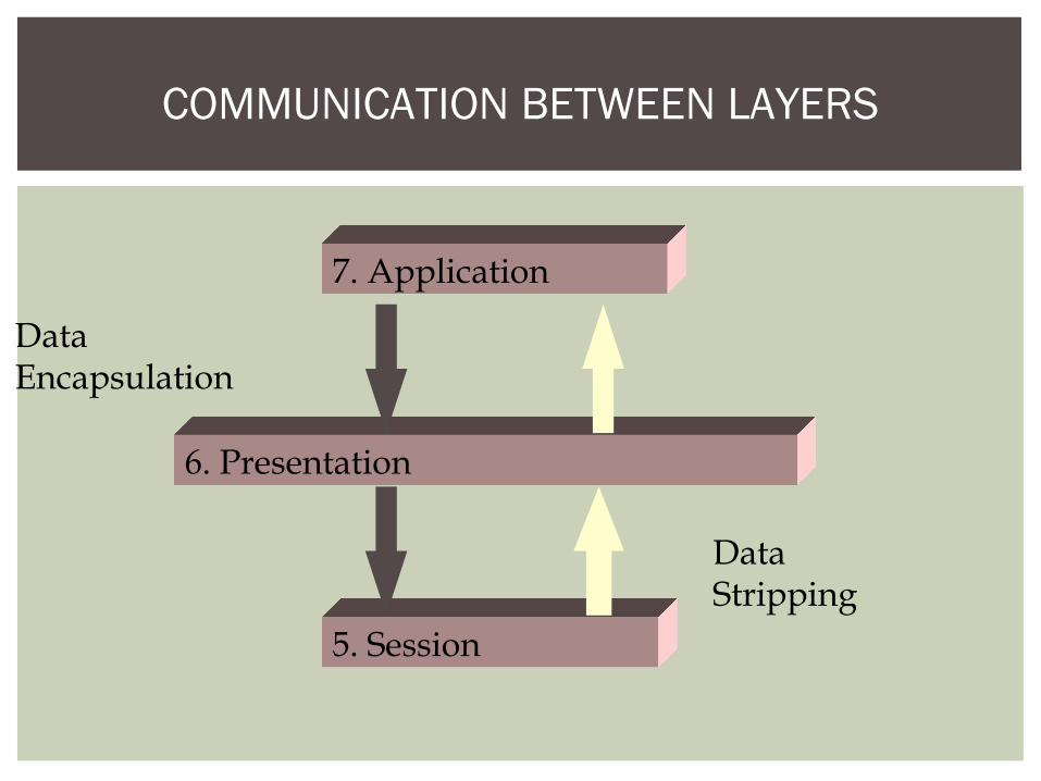
COMMUNICATION BETWEEN LAYERS
7. Application
6. Presentation
5. Session
DataEncapsulation
DataStripping
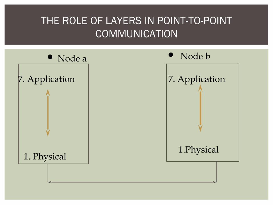
THE ROLE OF LAYERS IN POINT-TO-POINT COMMUNICATION
7. Application
1. Physical
7. Application
1.Physical
Node a Node b

The interaction between layers in the OSI model
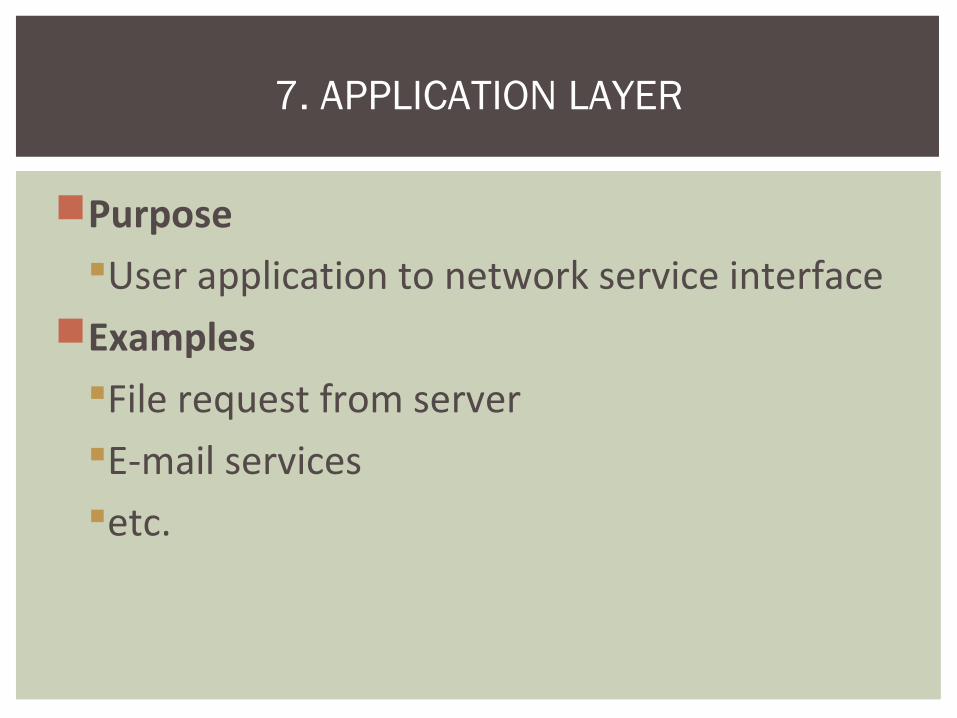
PurposeUser application to network service interface
ExamplesFile request from serverE-mail servicesetc.
7. APPLICATION LAYER

General network accessFlow controlError recovery
APPLICATION LAYER FUNCTION

Application layer

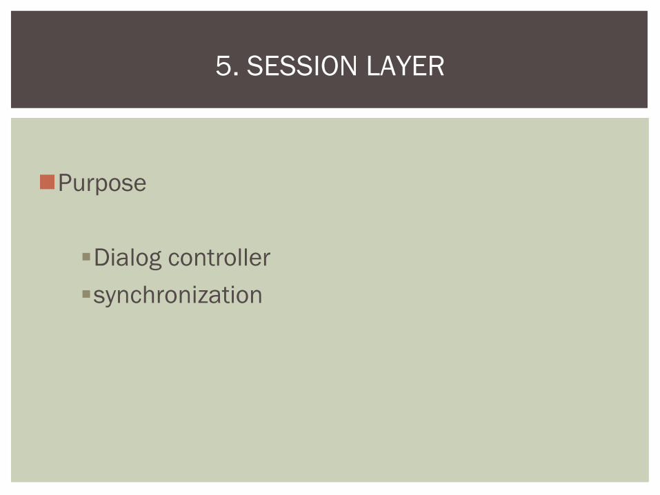
Purpose
Formats data for exchange between points of communication
•Ex: Between nodes in a networkExample
Redirector software
•Formats for transmission to the server
6. PRESENTATION LAYER

Data translation Encryption compression
PRESENTATION LAYER FUNCTION
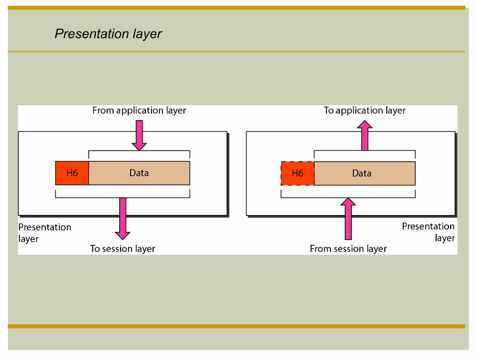
Presentation layer
Purpose
Dialog controller synchronization
5. SESSION LAYER
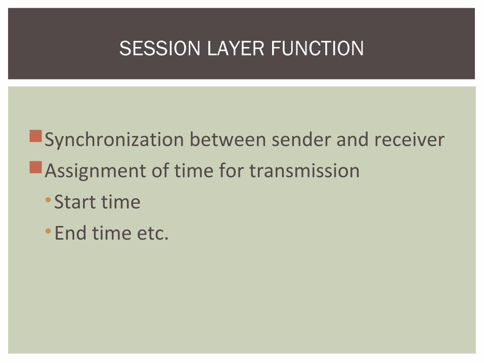
Synchronization between sender and receiverAssignment of time for transmission
•Start time•End time etc.
SESSION LAYER FUNCTION

Session layer

Purpose
Repackage proper and efficient delivery of packages
• In sequence
•Without duplication
•Error free
4. TRANSPORT LAYER
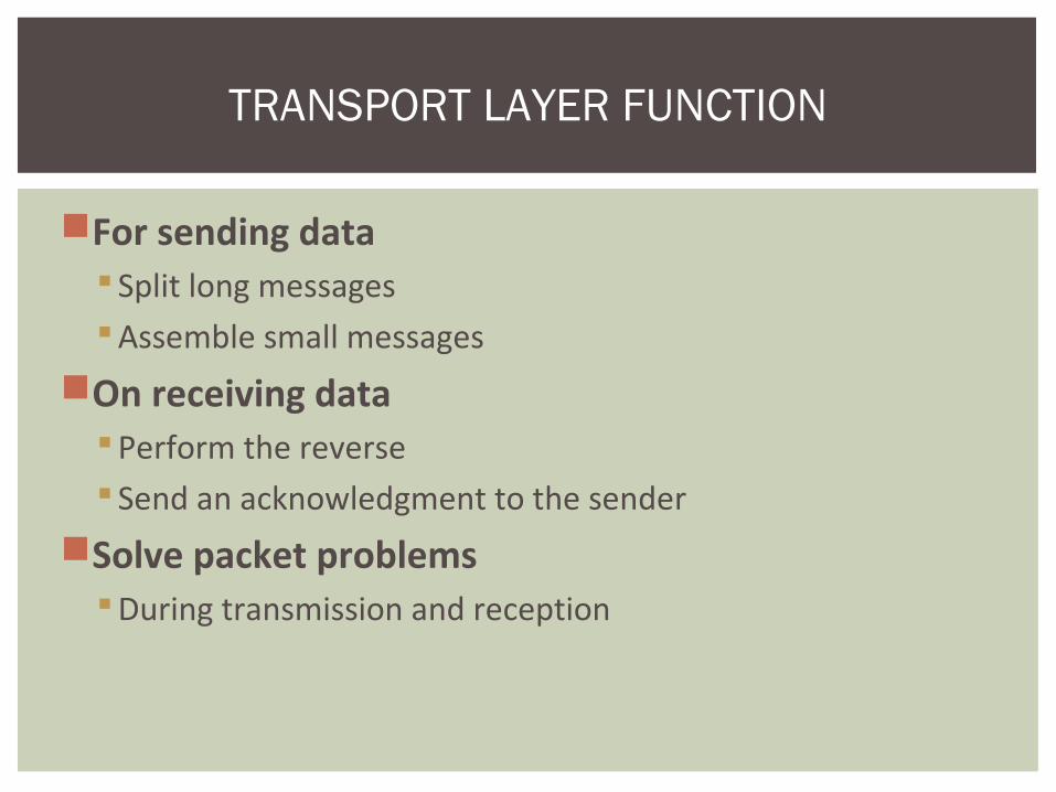
For sending data Split long messagesAssemble small messages
On receiving dataPerform the reverse Send an acknowledgment to the sender
Solve packet problemsDuring transmission and reception
TRANSPORT LAYER FUNCTION

Transport layer
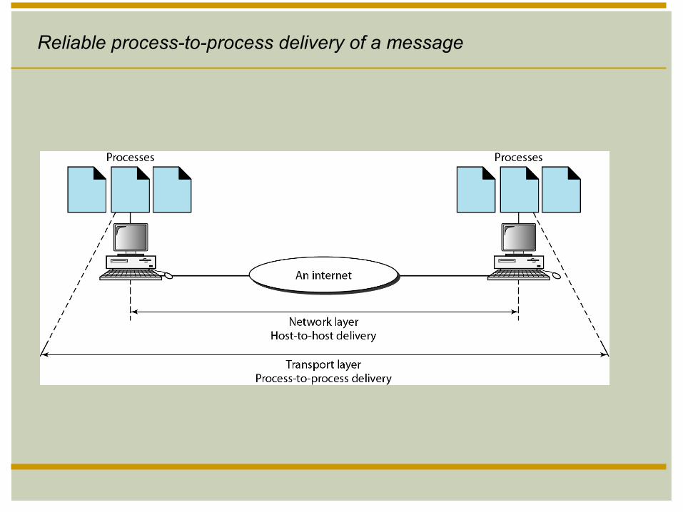
Reliable process-to-process delivery of a message

Purpose
Addressing and routing the packetsExample application at the router
If the packet size is large, splits into small packets
3. NETWORK LAYER

Address translation from logical to physicalRouting of data
Based on priorityBest path at the time of transmission
Congestion control
NETWORK LAYER FUNCTION

Network layer

A routing protocol is a protocol that specifies how router communicate with each other
Enables them to select routes between any two nodes on computer network
E.g OSPF , RIP
ROUTING PROTOCOL

PurposeManages the flow of data over the physical media
Responsible for error-free transmission over the physical media
Assures error-free data submission to the Network Layer
2. DATA LINK LAYER
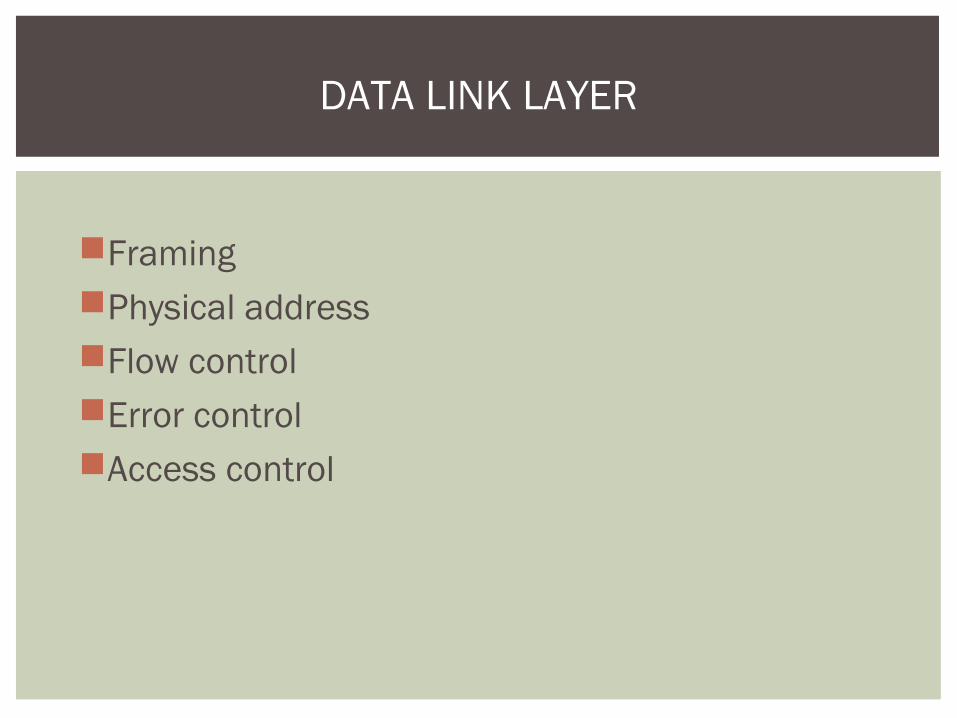
FramingPhysical addressFlow controlError controlAccess control
DATA LINK LAYER

Point of originPackages data for transmission over physical line
Receiving endPackages data for submission to the network layer
Deals with network transmission protocols IEEE 802. protocols
DATA LINK LAYER FUNCTION

Data link layer

Improvement to ISO ModelLogical Link Control (LLC) sub-layer
Error and flow control
Media Access Control (MAC) sub-layerApplies directly to network card communicationAccess control
DATA LINK LAYER SUBDIVISION

Network Interface Card driver
MEDIA ACCESS CONTROL APPLICATION
NETWORKSOFTWARE
NETWORKCARD
NIC Driverfacilitates data transfer
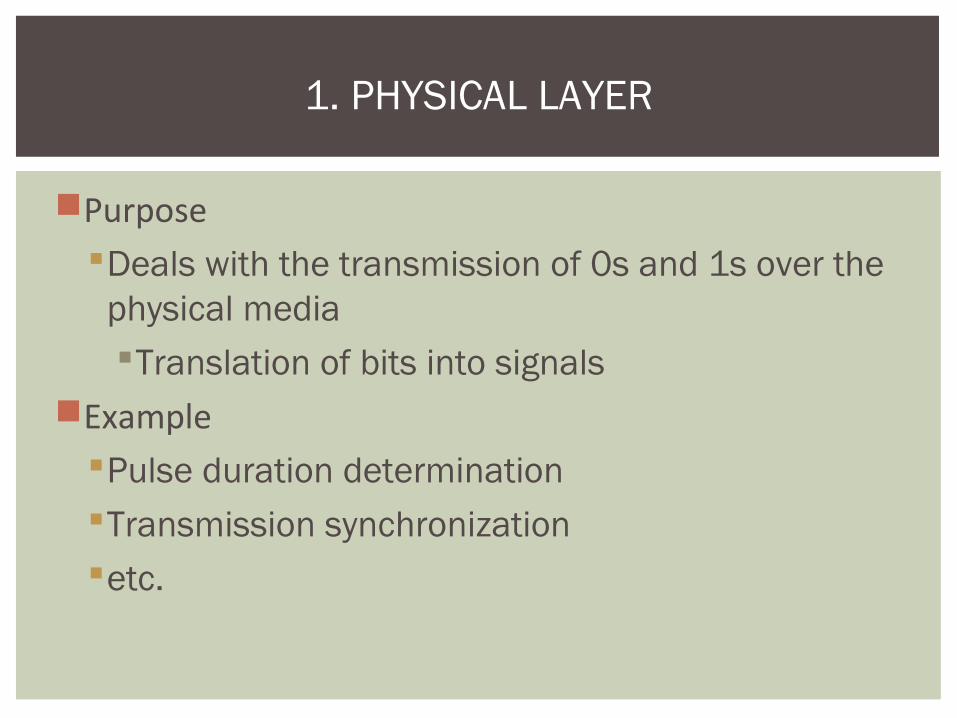
PurposeDeals with the transmission of 0s and 1s over the
physical mediaTranslation of bits into signals
ExamplePulse duration determinationTransmission synchronizationetc.
1. PHYSICAL LAYER

Physical characteristicRepresentation of bitsSynchronization of bitsPhysical topolgyTransmission mode
PHYSICAL LAYER
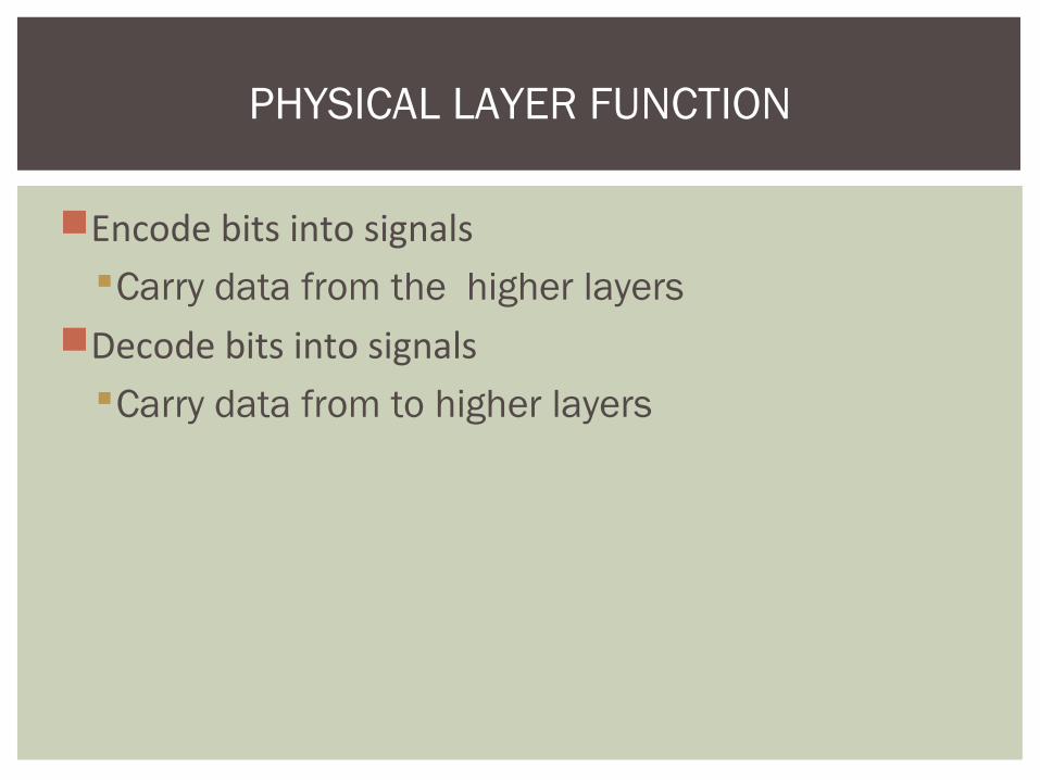
Encode bits into signalsCarry data from the higher layers
Decode bits into signalsCarry data from to higher layers
PHYSICAL LAYER FUNCTION

Physical layer

At each layer, additional information is added to the data packet
Trailer Packet arrival information and Some Header
Information Added at Various Layers
• Receiver’s address• Sender’s address
LAYER OPERATIONS
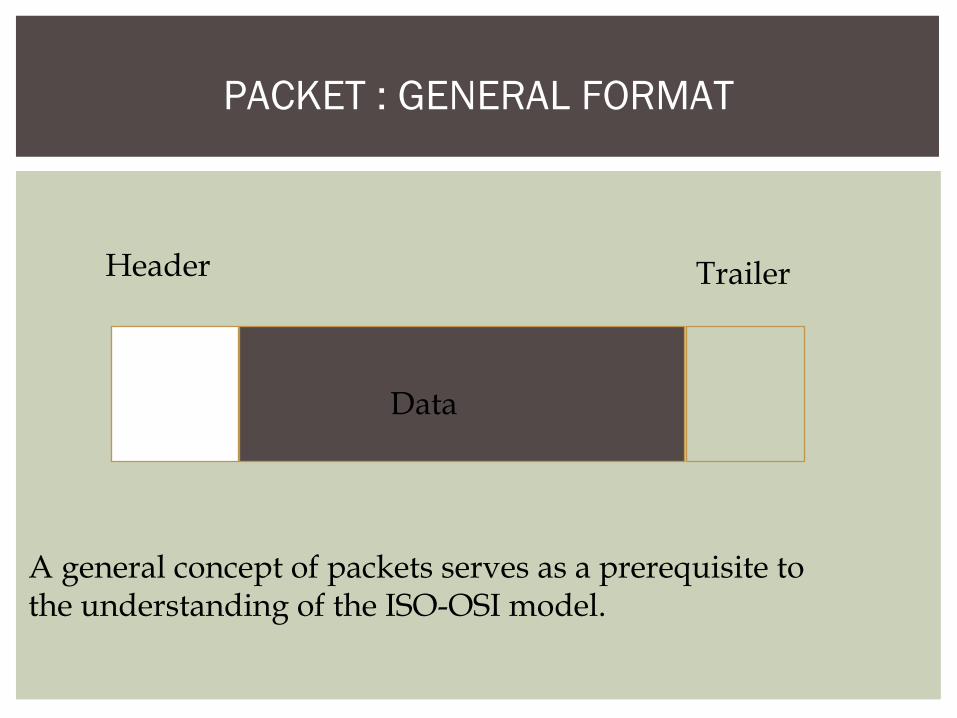
PACKET : GENERAL FORMAT
Header Trailer
Data
A general concept of packets serves as a prerequisite tothe understanding of the ISO-OSI model.

FORMATTING OF DATA THROUGH THE LAYERS
Application Header Presentation Header Session Header
Transport HeaderNetwork Header
Data Link Header and Trailer Physical Frame Preamble

An exchange using the OSI model

SUMMARY


Thank You