Open System Interconnection Model (OSI) Connecting Devices...
32
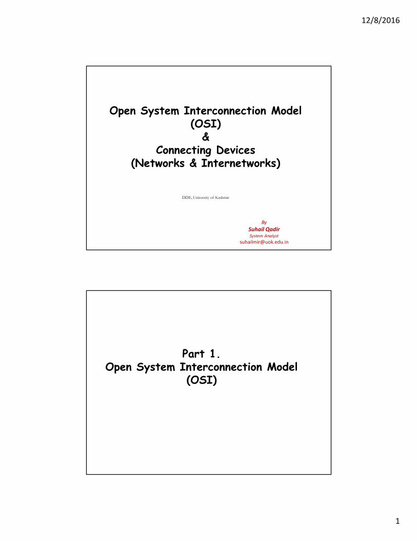
12/8/2016 1 By Suhail Qadir System Analyst [email protected] Open System Interconnection Model (OSI) & Connecting Devices (Networks & Internetworks) DDE, University of Kashmir Part 1. Open System Interconnection Model (OSI)
Transcript of Open System Interconnection Model (OSI) Connecting Devices...
12/8/2016
1
By
Suhail QadirSystem Analyst
Open System Interconnection Model (OSI)
&Connecting Devices
(Networks & Internetworks)
DDE, University of Kashmir
Part 1.Open System Interconnection Model
(OSI)
12/8/2016
2
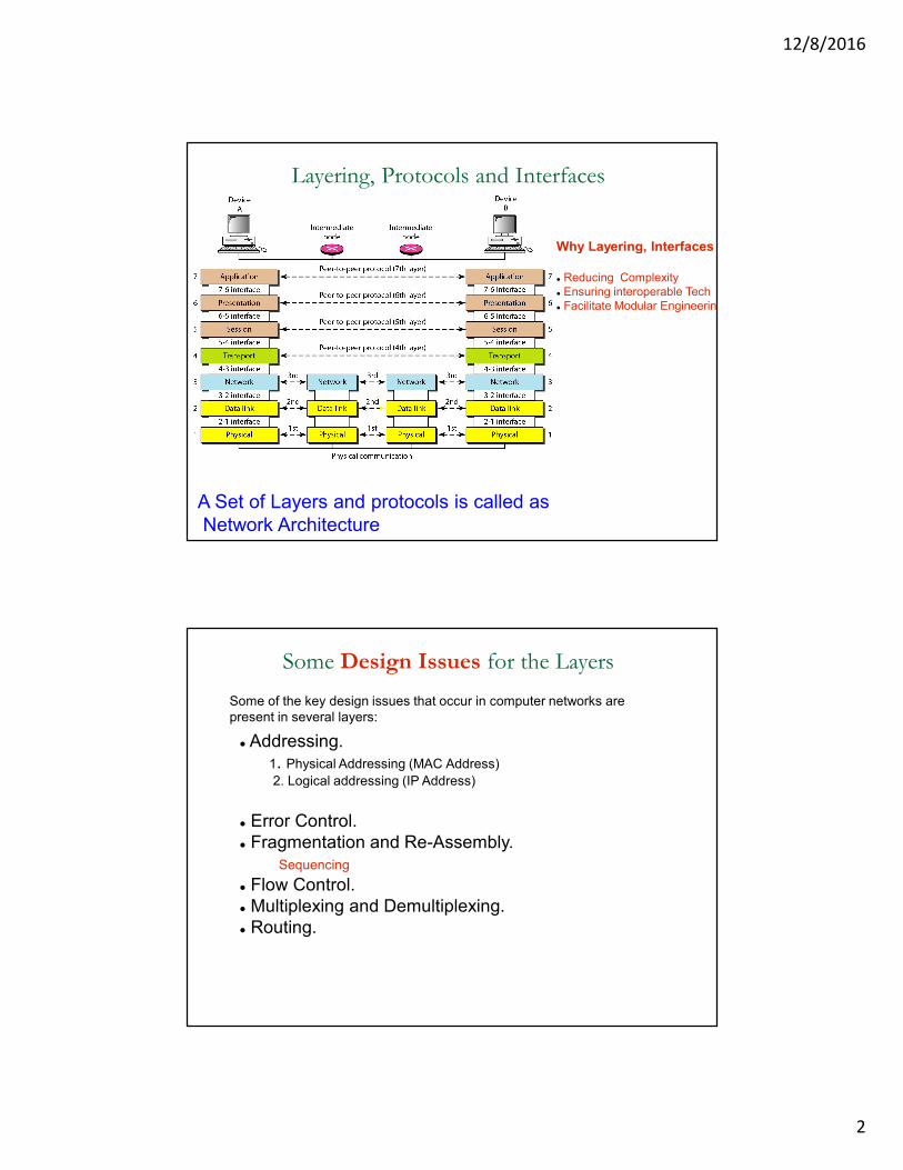
Layering, Protocols and Interfaces
Why Layering, Interfaces ?
� Reducing Complexity
� Ensuring interoperable Tech
� Facilitate Modular Engineering
A Set of Layers and protocols is called as
Network Architecture
Some Design Issues for the Layers
� Addressing.
1. Physical Addressing (MAC Address)
2. Logical addressing (IP Address)
� Error Control.
� Fragmentation and Re-Assembly.
Sequencing
� Flow Control.
� Multiplexing and Demultiplexing.
� Routing.
Some of the key design issues that occur in computer networks are
present in several layers:
12/8/2016
3
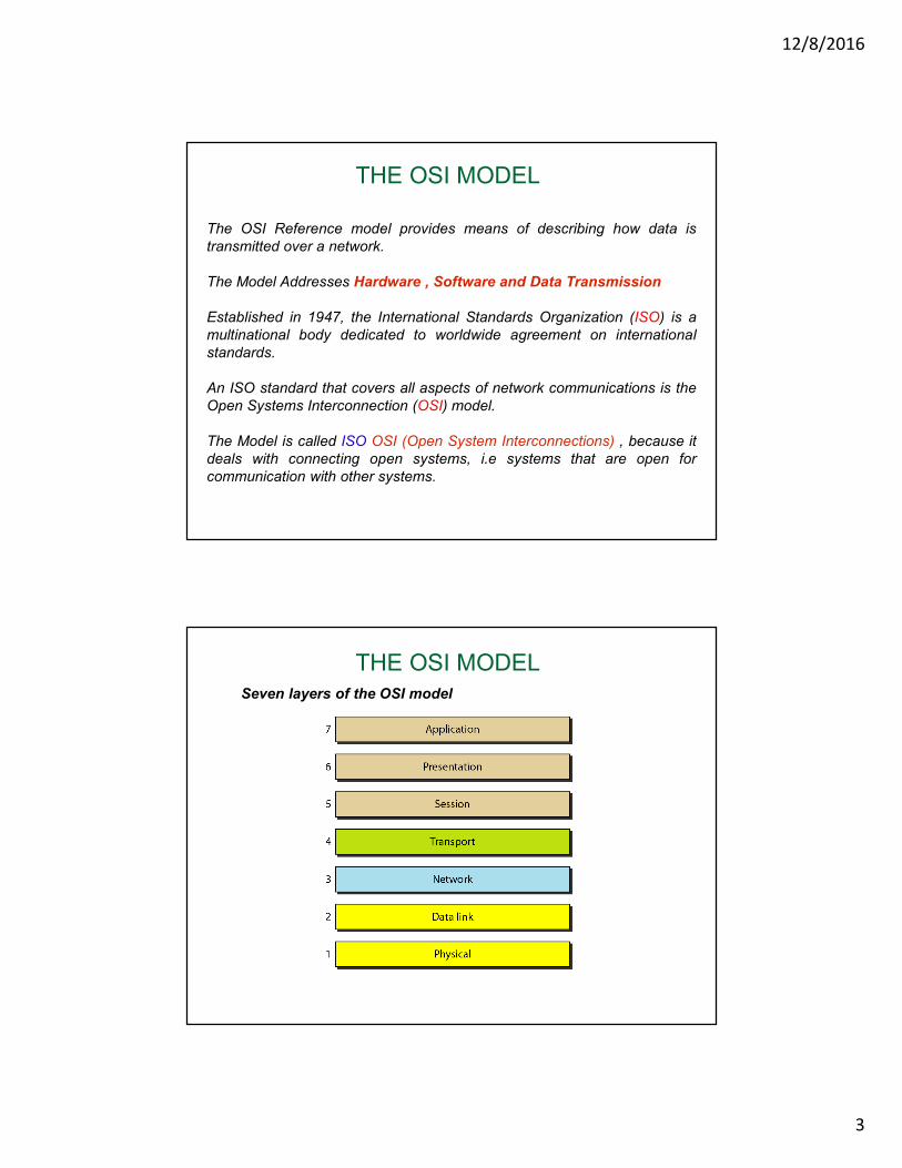
THE OSI MODEL
The OSI Reference model provides means of describing how data is
transmitted over a network.
The Model Addresses Hardware , Software and Data Transmission
Established in 1947, the International Standards Organization (ISO) is a
multinational body dedicated to worldwide agreement on international
standards.
An ISO standard that covers all aspects of network communications is the
Open Systems Interconnection (OSI) model.
The Model is called ISO OSI (Open System Interconnections) , because it
deals with connecting open systems, i.e systems that are open for
communication with other systems.
THE OSI MODEL
Seven layers of the OSI model
12/8/2016
4
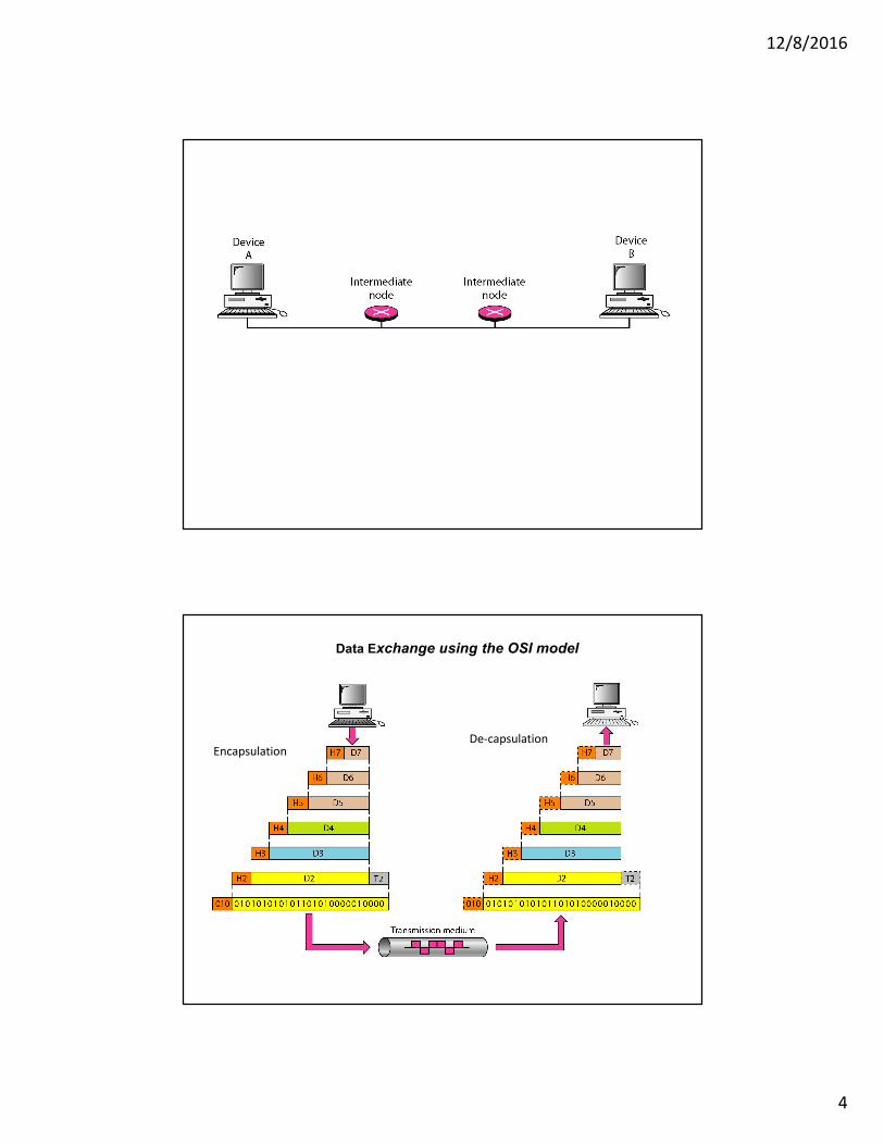
Data Exchange using the OSI model
EncapsulationDe-capsulation
12/8/2016
5
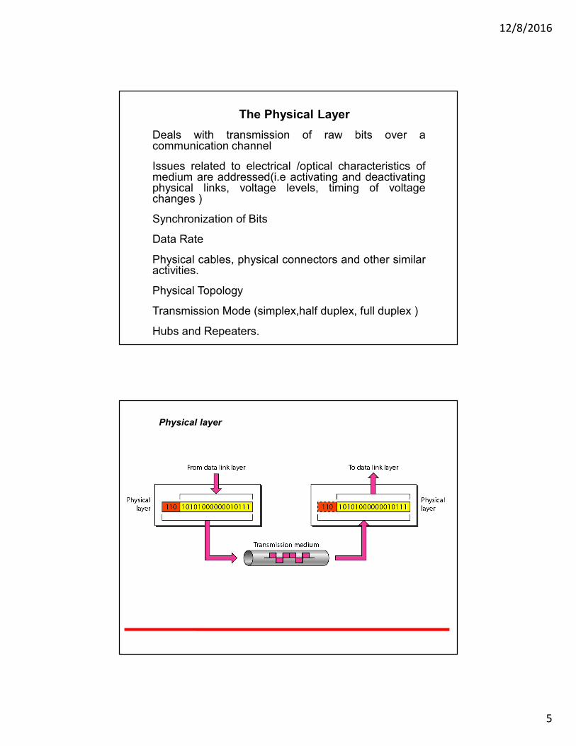
The Physical Layer
Deals with transmission of raw bits over acommunication channel
Issues related to electrical /optical characteristics ofmedium are addressed(i.e activating and deactivatingphysical links, voltage levels, timing of voltagechanges )
Synchronization of Bits
Data Rate
Physical cables, physical connectors and other similaractivities.
Physical Topology
Transmission Mode (simplex,half duplex, full duplex )
Hubs and Repeaters.
Physical layer

12/8/2016
6
Data Link Layer Frame
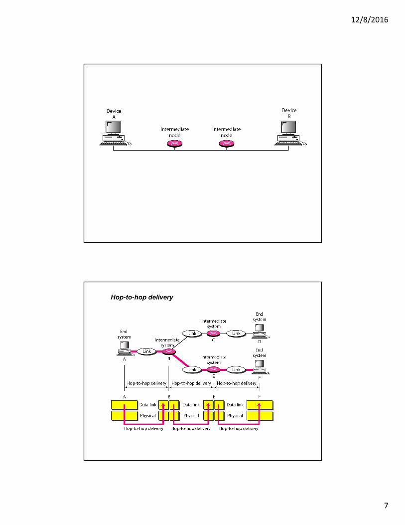
Data Link Layer
The data link layer is responsible for moving
frames from one hop (node) to the next.
Organizes data bits into frames whose integrity can bechecked (error detection)
Transmits frames sequentially using necessarysynchronization, error-control and flow-control.
Physical Addressing
Link Layer Protocols Include:
LAN : Ethernet, 802.3, 802.11, Token ring ()
WAN : HDLC , PPP, Packet over SONET (POS),
Bridges, Swithes.
12/8/2016
7
Hop-to-hop delivery
12/8/2016
8
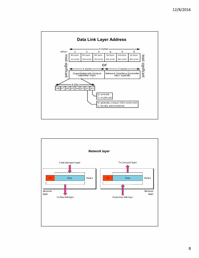
Data Link Layer Address
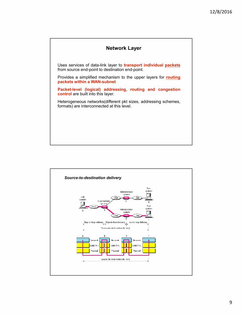
Network layer
12/8/2016
9
Network Layer
Uses services of data-link layer to transport individual packetsfrom source end-point to destination end-point.
Provides a simplified mechanism to the upper layers for routingpackets within a WAN-subnet
Packet-level (logical) addressing, routing and congestioncontrol are built into this layer.
Heterogeneous networks(different pkt sizes, addressing schemes,formats) are interconnected at this level.
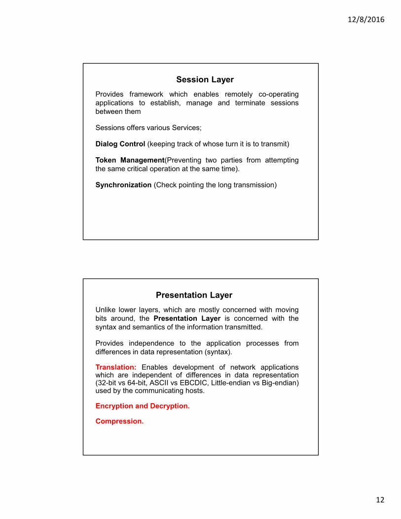
Source-to-destination delivery

12/8/2016
10
Network layer
Transport Layer
The first end-to-end layer which establishes communicationbetween source and destination processes ( running on remotehosts).
Service Point Addressing (Port Addressing).
Segmentation and Reassembly.
Connection Control.
– Connection Oriented (Reliable)
– Connectionless (UN-reliable)
Flow Control (end to end).
Error Control (end to end).

12/8/2016
11
Connection Oriented :
TCP provides reliable, connection-oriented service on top of IP.
Acknowledgement of IP packets
Applications that use TCP:
HTTP, FTP, telnet,SMTP, POP3 and some Video/Audio Streaming
Connectionless :
UDP - An unreliable, connection-less protocol on top op IP.
No acks and re-transmits, Packet Drop
Applications that use UDP, not TCP:
Streaming media, e.g. RealAudio and RealVideo.
VoIP, Online multiplayer games like Counter Strike
Transport layer Data Segments
12/8/2016
12
Session Layer
Provides framework which enables remotely co-operating
applications to establish, manage and terminate sessions
between them
Sessions offers various Services;
Dialog Control (keeping track of whose turn it is to transmit)
Token Management(Preventing two parties from attempting
the same critical operation at the same time).
Synchronization (Check pointing the long transmission)
Presentation Layer
Unlike lower layers, which are mostly concerned with moving
bits around, the Presentation Layer is concerned with the
syntax and semantics of the information transmitted.
Provides independence to the application processes from
differences in data representation (syntax).
Translation: Enables development of network applicationswhich are independent of differences in data representation(32-bit vs 64-bit, ASCII vs EBCDIC, Little-endian vs Big-endian)used by the communicating hosts.
Encryption and Decryption.
Compression.

12/8/2016
13
Application Layer
Interfaces with the Application Programs and Provides
network access to the applications
Includes protocols Used by the Application Programs,
which enable exchange of files/data between hosts
Examples: FTP, Telnet (virtual terminal ), RLOGIN, HTTP(
retrieves HTML pages from a web server), SMTP, POP.
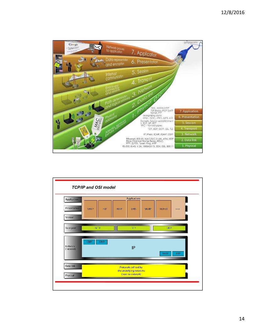
Summary of layers
12/8/2016
14
Summary of layers
TCP/IP and OSI model

12/8/2016
15
Part 2Connecting Devices
(Networks & Internetworks)
Five connecting devices
� Repeaters
� Hubs
� Bridges
� Switches
� Routers
12/8/2016
16
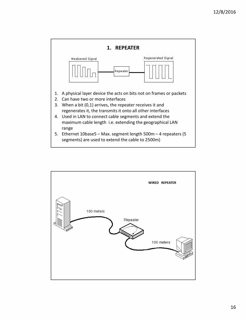
1. REPEATER
1. A physical layer device the acts on bits not on frames or packets
2. Can have two or more interfaces
3. When a bit (0,1) arrives, the repeater receives it and
regenerates it, the transmits it onto all other interfaces
4. Used in LAN to connect cable segments and extend the
maximum cable length i.e. extending the geographical LAN
range
5. Ethernet 10base5 – Max. segment length 500m – 4 repeaters (5
segments) are used to extend the cable to 2500m)
WIRED REPEATER

12/8/2016
17
WIRELESS REPEATER

12/8/2016
18
2. HUB
MULTI-PORT
REPEATER ???
Speeds : 10 Mbps and 100 Mbps.
• Acts on the physical layer
• Operate on bits rather than frames
• Also called multiport repeater
• Used to connect stations adapters in a physical star topology but logically bus
• Connection to the hub consists of two pairs of twisted pair wire one for
transmission and the other for receiving.
• Hub receives a bit from an adapter and sends it to all the other adapters without
implementing any access method.
• does not do filtering (forward a frame into a specific destination or drop it) just it
copy the received frame onto all other links
• The entire hub forms a single collision domain, and a single Broadcast domain
• Collision domain: is that part of the network (set of NICs) when two or more nodes
transmit at the same time collision will happen.
• Broadcast domain: is that part of the network (set of NIC) where each NIC can 'see'
other NICs' traffic broadcast messages.
• Multiple Hubs can be used to extend the network length
2. HUB continued..
12/8/2016
19
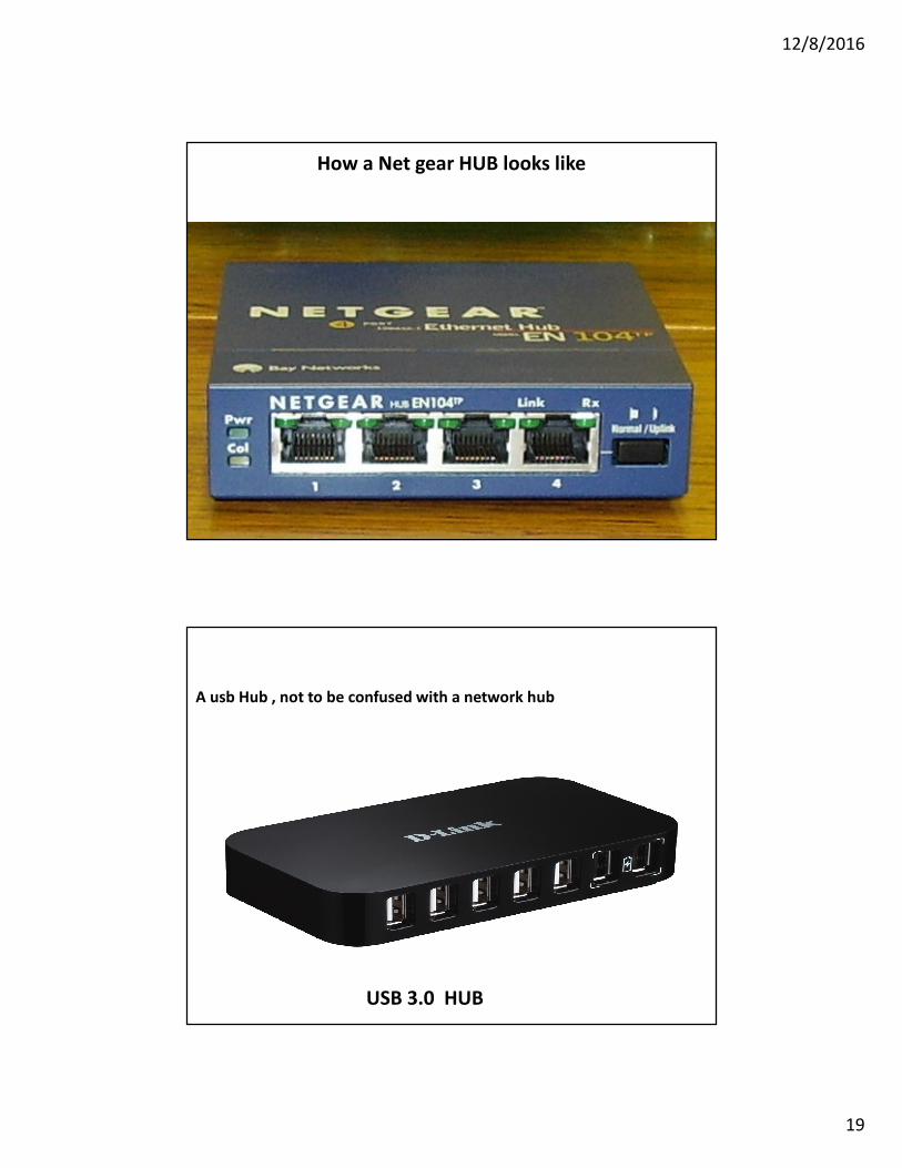
How a Net gear HUB looks like
USB 3.0 HUB
A usb Hub , not to be confused with a network hub
12/8/2016
20
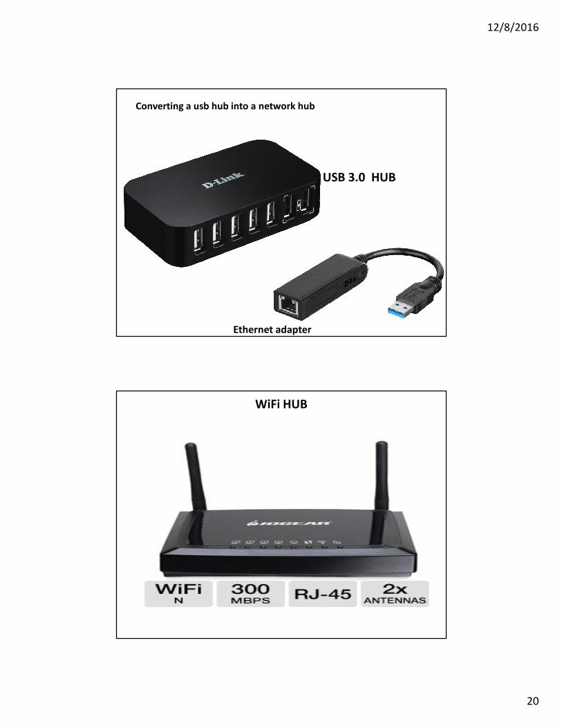
USB 3.0 HUB
Ethernet adapter
Converting a usb hub into a network hub
WiFi HUB
12/8/2016
21
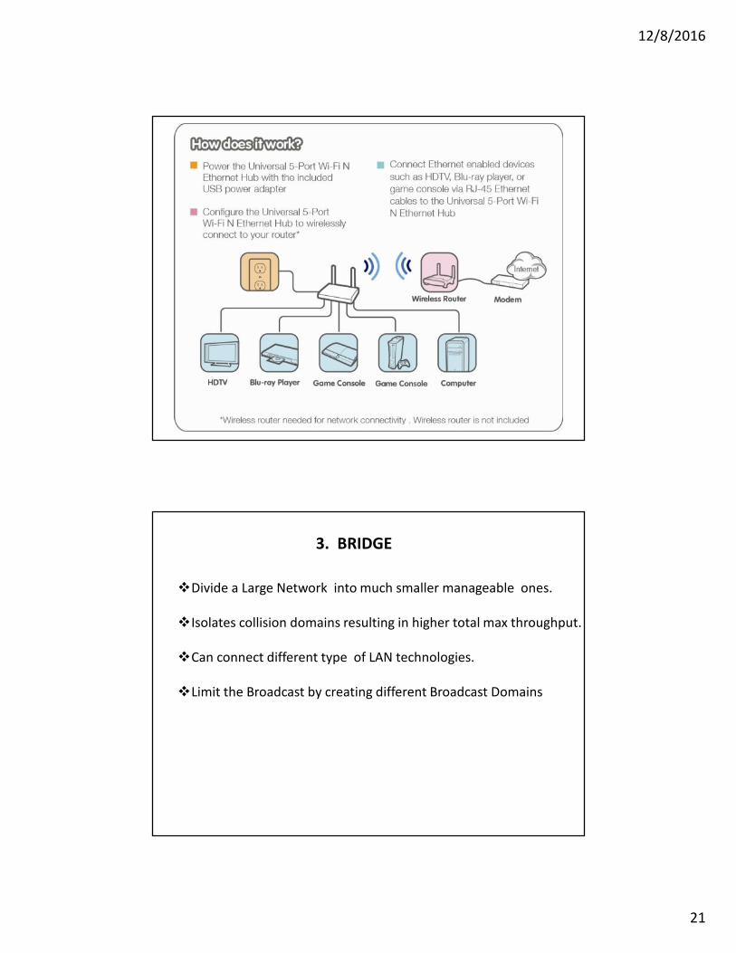
3. BRIDGE
�Divide a Large Network into much smaller manageable ones.
�Isolates collision domains resulting in higher total max throughput.
�Can connect different type of LAN technologies.
�Limit the Broadcast by creating different Broadcast Domains

12/8/2016
22
A bridge dividing a lan into 2
segiments i.e.
2 broad cast domains
A bridge connecting
different lan technologies
12/8/2016
23
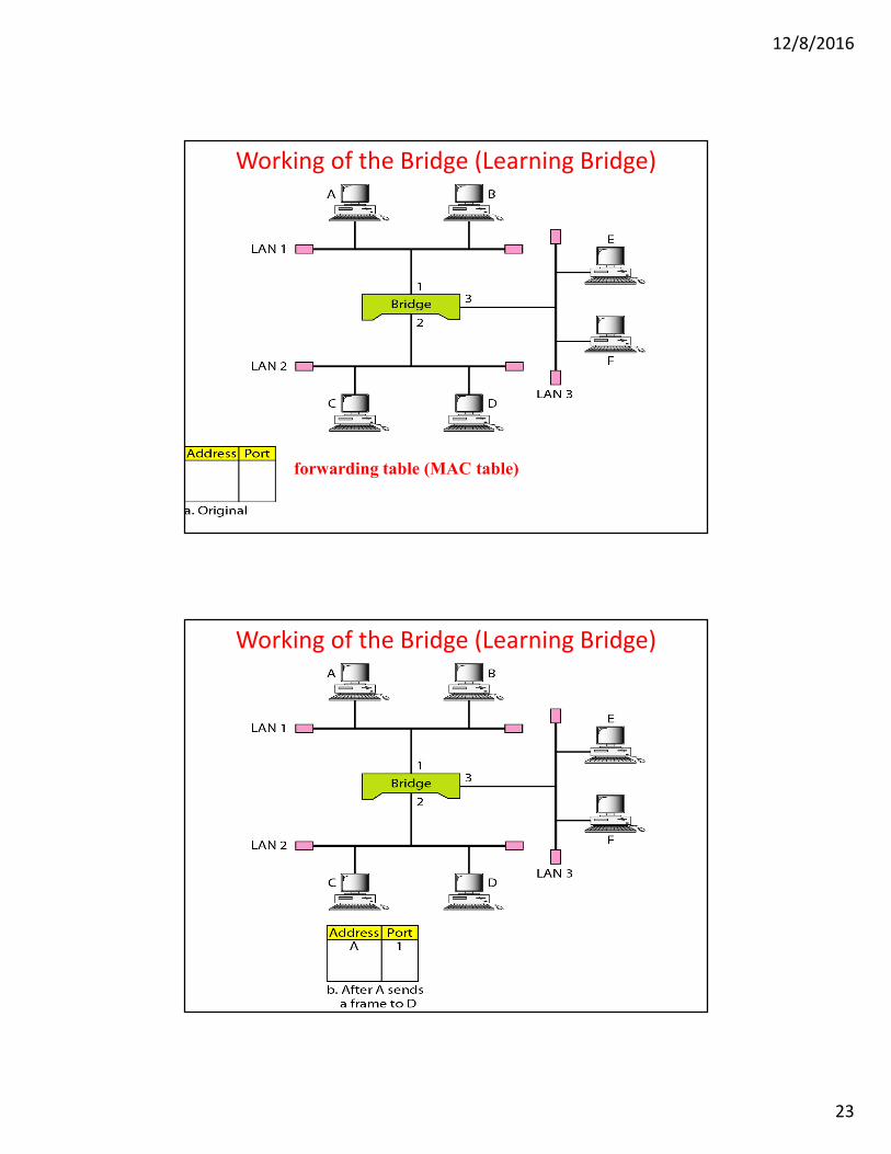
Working of the Bridge (Learning Bridge)
forwarding table (MAC table)
Working of the Bridge (Learning Bridge)
12/8/2016
24
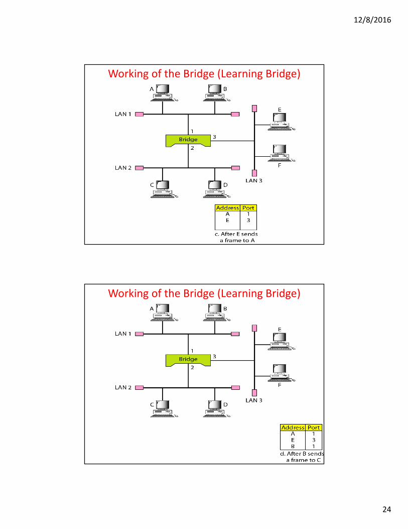
Working of the Bridge (Learning Bridge)
Working of the Bridge (Learning Bridge)
12/8/2016
25
There are two types of Transparent Bridge Modes:
� Store-and-Forward: Stores the entire frame and verifies the CRC
before forwarding the frame. If a CRC error is detected, the frame is
discarded.
� Cut-Through: Forwards the frame just after it reads the destination
MAC address without performing a CRC check.
A transparent bridge does not need programming but observes all
traffic and builds routing tables from this observation.
This observation is called backward learning.
Transparent bridge
A transparent bridge is found with CSMA/CD LANs
Source-route Bridges
A source-routing bridge is found with token ring networks.
Source-routing bridges do not learn from watching tables.
When a workstation wants to send a frame, it must know the
exact path of network / bridge
If a workstation does not know the exact path, it sends out a
discovery frame.
The discovery frame makes its way to the final destination, then
as it returns, it records the path.
12/8/2016
26
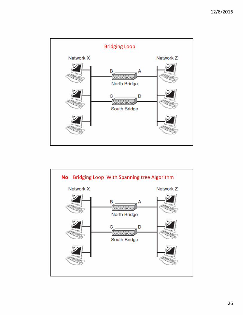
Bridging Loop
No Bridging Loop With Spanning tree Algorithm

12/8/2016
27
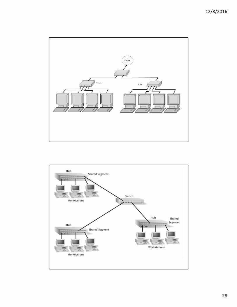
4. SWITCH
� A switch is a combination of a hub and a bridge.
� Allows more than one device connected to the switch directly to
transmit simultaneously
� It can interconnect two or more workstations, but like a bridge, it
observes traffic flow and learns.When a frame arrives at a switch, the switch examines the destination address and forwards the frame out the one necessary connection.Two types :
Store-and-forward: switch receives the whole a frame on the input line, buffers it briefly , performs error checking, then routes it to the appropriate output line (similar to bridge). Buffering will cause some delay.Cut-through: based on the fact that the destination address appears at the beginning of the MAC frame, so once the address is recognized the frame is directly sent to the appropriate output line if the output buffer is empty (no need to buffer it). � no buffering delay � NO ERROR CHECKING
Full-Duplex operation
Isolated collision domains
12/8/2016
28

12/8/2016
29
�Using the Virtual LAN technology will allow grouping computers
logically instead of physically.
�VLAN divides the physical LAN into several Logical LANs
called VLANs
� Switch maintains a look up table to know to which LAN a
machine belongs to.
VLAN1: Ports 1,2,5,7
VLAN2: Ports 3,4,6
VLAN3: Ports 8,9,10
1 2 3 4 5 6 7 8 9 10
Separate broadcast domain �
separate network
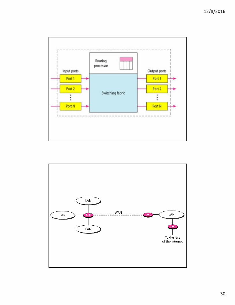
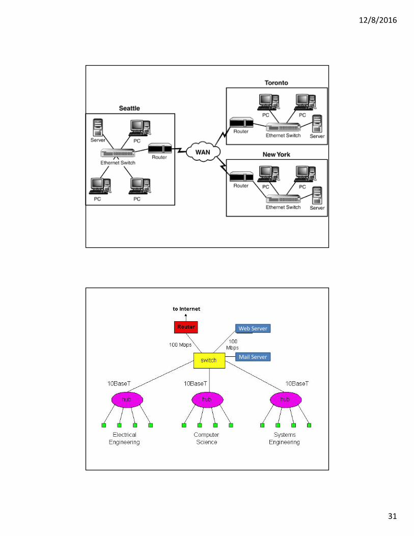
5. ROUTER
� Operates at network layer = deals with packets not frames� Connect LANs and WANs with similar or different protocols
together� Switches and bridges isolate collision domains but forward
broadcast messages to all LANs connected to them. Routers isolate both collision domains and broadcast domains
� Acts like normal stations on a network, but have more than onenetwork address (an address to each connected network)
� Deals with global address ( network layer address (IP)) not local address (MAC address)
� Routers Communicate with each other and exchange routing information
� Determine best route using routing algorithm by special software installed on them
� Forward traffic if information on destination is available otherwise discard it (not like a switch or bridge)
12/8/2016
30
12/8/2016
31
Web Server
Mail Server
12/8/2016
32
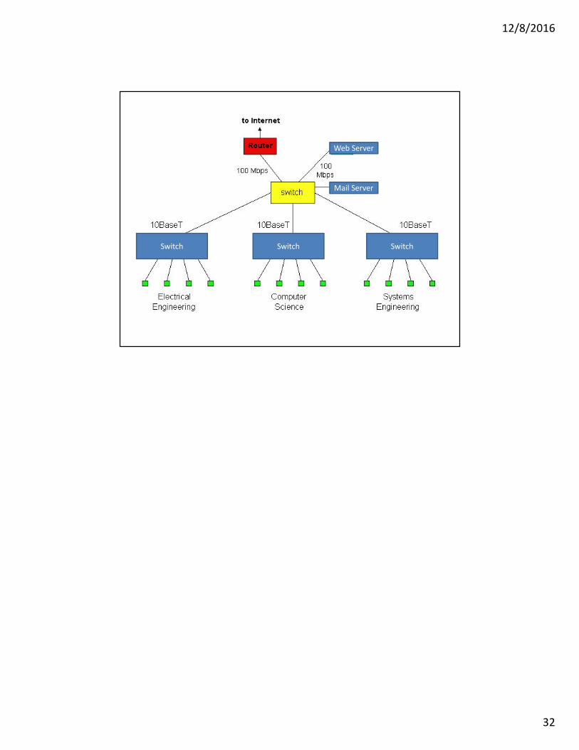
Web Server
Mail Server
Switch Switch Switch