OSI Model - Internodemarty_one/Study Guide.pdf · In the OSI model the Application, Presentation...
52
OSI Model Layer Description Function 7 Application Network processes to Applications. Provides network services to applications such as email, web browsing, file transfer. Telnet, FTP, TFTP, SMTP, SNMP, HTTP, BOOTP, DHCP, RIP, OSPF 6 Presentation Data Representation Ensure that the data is readable by the receiving system. Format of data. Data Structures. Negotiates data transfer syntax for application layer. 5 Session Inter host Communication Establishes, manages and terminates sessions between applications. Examples of dession layer protocols are : NFS, SQL, RPC, ASP (Appletalk Session Protocol), SCP, NetBIOS, Named PIPES 4 Transport End-To-End Connections Concerned with transportation issues between hosts. Data transport reliability. Establish, maintain and terminate virtual circuits. Fault detection and recovery information flow control. TCPIP, UDP, SPX (Novell), NetBEUI 3 Network Network Address and Best Path Determination. Provides reliable transfer of data across media. Physical addressing, network topology, error notification and flow control. Routes information in the network. Ping, trace route, “show ip route”. IP, IPX,ARP,RARP, ICMP, Q.931. Routing occurs on this layer. 2 Data Link Direct Link Control, Access to Media. Provides reliable transfer of data across media. Physical addressing, network topology, error notification and flow control. MAC Address. Protocols that operate on this layer are CDP, PPP, FDDI, Frame Relay, ATM, HDLC, LLC, Swtiches and Hubs 1 Physical Binary Transmission. Wires, connectors, voltages and data rates, V.35, RS-232, T1, E1, Q.911 Peer to Peer communication's Host A Host B Application Data Application Presentation Data Presentation Session Data Session Transport Segments Transport Network Packets Network Data Link Frames Data Link Physical Bits Physical Packet encapsulation:
Transcript of OSI Model - Internodemarty_one/Study Guide.pdf · In the OSI model the Application, Presentation...

OSI ModelLayer Description Function
7 Application Network processes to Applications.
Provides network services to applications such as email, web browsing, file transfer.Telnet, FTP, TFTP, SMTP, SNMP, HTTP, BOOTP, DHCP, RIP, OSPF
6 Presentation Data Representation
Ensure that the data is readable by the receiving system. Format of data. DataStructures. Negotiates data transfer syntax for application layer.
5 Session Inter host Communication
Establishes, manages and terminates sessions between applications. Examples ofdession layer protocols are : NFS, SQL, RPC, ASP (Appletalk Session Protocol), SCP,NetBIOS, Named PIPES
4 Transport End-To-End Connections
Concerned with transportation issues between hosts. Data transport reliability.Establish, maintain and terminate virtual circuits. Fault detection and recoveryinformation flow control. TCPIP, UDP, SPX (Novell), NetBEUI
3 Network Network Address and Best Path Determination.
Provides reliable transfer of data across media. Physical addressing, network topology,error notification and flow control. Routes information in the network. Ping, trace route,“show ip route”. IP, IPX,ARP,RARP, ICMP, Q.931. Routing occurs on this layer.
2 Data Link Direct Link Control, Access to Media.
Provides reliable transfer of data across media. Physical addressing, network topology,error notification and flow control. MAC Address. Protocols that operate on this layerare CDP, PPP, FDDI, Frame Relay, ATM, HDLC, LLC, Swtiches and Hubs
1 Physical Binary Transmission.
Wires, connectors, voltages and data rates, V.35, RS-232, T1, E1, Q.911
Peer to Peer communication'sHost A Host B
Application Data Application
Presentation Data Presentation
Session Data Session
Transport Segments Transport
Network Packets Network
Data Link Frames Data Link
Physical Bits Physical
Packet encapsulation:

As a packet travels through an internetwork to its final destination, the layer 2 frame headers and trailers are removed andreplaced at every layer 3 device. This is because layer 2 data units and frames are for local addressing. Layer 3 data unitsand packets are for end-to-end addressing.
Layer 2 ethernet frames are designed to work within a broadcast domain using their mac address. Other types of layer 2frames includes PPP and Frame Relay.
The most common non-routable protocol is NetBEUI. NetBEUI is a small, fast, efficient protocol that is limited to framedelivery within one segment only.
TCP/IP ModelLayer Description Function
4 Application Combines the Application, Presentation and Session layers into one Application layer(FTP, TFTP, HTTP, SMTP, POP3, DNS, Telnet, SNMP)
3 Transport Remains by itself. TCP:Connection oriented. UDP: Connectionless. Provides servicesfrom the source host to the destination host. This layer segments and re-assemblesupper layer applications into the same data stream end-points. Provides flow controland reliability. RTP, SCTP
2 Internet Commonly referred to as the ip layer as this layer isolates the upper layers from theunderlying network connections. Address Resolution, best effort delivery of routingpackets. Connectionless. IP
1 Network Access Combines the Data Link and Network Layer into the Network Access layer. This layerdetermines how ip utilizes the existing data link and how the communication signals aresent along the wire.
Some key things to remember about the two different models are:The tcp/ip model, the application and transport layer fall under the protocol description and the Internet andNetwork Access layers are the Network description.
In the OSI model the Application, Presentation and Session layers are considered the application layers and theTransport, Network, Data Link and Physical layers are the data flow layers.
The TCP/IP transport layer uses a three way handshake to establish a connection. A Three Way Handshake is necessarybecause sequence numbers are not tied to a global clock. During the initial connection of TCP/IP the sliding window size ifagreed upon before the actual sending and receiving of data. The window size refers to “sliding windows” which defines thenumber of packets a destination can receive before sending an acknowledgment back to the source. If there is congestionat the destination and continually drops one out of three packets then the source will start to transmit the data with a smallerwindow size. After the source has received the packets of data it responds with forward reference acknowledgment.
TCP is a connection oriented layer 4 protocol that provides reliable full-duplex data transmission. UDP is a connectionlesstransport protocol in the TCP/IP stack. This is a simple protocol that exchanges datagrams without acknowledgments orguaranteed delivery. Both of these protocols use port numbers to pass information to the upper layers.
Ports • 255 and below are reserved for public applications• 255 – 1023 are assigned to companies for marketable applications• 1023 and above are un-regulated.

OSI Layers that network devices operate atLayer Devices
7-4 Mainframe, File server, Computer, Laptop, IP Phone
3 Router
2 Bridge, Work group Switch, ATM Fast Gigabit Switch, Access Point, NIC, Bridge
1 Modem, Hub, Satellite Dish, Repeater
Networking DevicesRepeater Regenerates and retimes network signalsHubs Concentrate network network devices. They retime network signal and regenerate packetsSwitches Same as a hub but they segment network devices into their own collision domain.Bridges Connects different networks together intelligently.Router Connects multiple networks together (usually over geographic distances), control which traffic goes where.
Although routers are generally considered to be a DTE device they can also act as a DCE device.Wireless Are like a hub where there is one central point but no wires, they consist of an access point and a receiver.
Access points concentrate network traffic back on the wire.NIC Network Interface Card. These are used by computers to communicate on networks. Each NIC has a MAC
address this is a globally unique identifying address. Which is 48 bits long (24 bits comprises of the manufacturer ID and 24 bits for a unique id defined by the manufacturer.
Hubs and Repeaters extend collision domains, while bridges, switches and routers split collision domain. But switches stillextend broadcast domains where as routers and bridges will split broadcast domains.
The 5-4-3-2-1 rules that the following guide lines should not be exceeded:• five segments of the network media• four repeaters or hubs• three host segments of the network• two link sections (no hosts)• one large collision domain
The 5-4-3-2-1 rule provides guidelines to keep round-trip delay tie in a shared network within acceptable limits.
Hubs and repeaters both operate on layer 1 only, there is no intelligence built into them. Switches and bridges operate onlayer 2 of the osi model and perform path determination. Routers operate on layer 3 as they also perform path determinationon the network address of the packet.
NOTE: As packets pass through each network device whether it be a switch, router or token ring. The mac address alwayschanges to the mac address of the next interface, the IP address always remains the same. The reason for this is becauseof the nature of how data link layer addressing works.
Switches have three main modes of operation Store and Forward, Fast Forward and Cut Through. • Store and Forward – buffers the entire packet and then performs path determination• Fast forward – bufferers the first 64 bits of the packet and then preforms path determination• Cut Through – is where the packet is buffered only until the destination address can be read and then path
determination is preformed.
When collisions occur in a networked environment. The station that first detects a collision generates a jam signal which is32 bits in length and lasts long enough for all stations on the segment to see the collision. Then a back algorithm is invokedthat generates a random amount of time the host uses to wait (the amount of time will always be different on every machine)when the time has expired the hosts involved in the collision will not have priority to send again for a set period. This allowsother machines on the network to send their information before the other machines begin sending their information again.
When a device receives a packet it must process the first three layers of the osi model to determine whether the packet isintended for it or not. Since ethernet is a non-deterministic protocol, the frame gets sent to every host in the broadcastdomain, and therefore every host must process the packet to the point where it can identify whether the it is the intendeddestination.

Network CablingTIA/EIA-568-A
Specifications for governing Cable Performance. It calls for running two cables, one for voice and one for data toeach outlet. Of the two cables, the one for voice must be four pair UTP. Cat5 is one of the most frequently used ininstallations today.
Types of Wireless networking frames:Management Frames• Association request frame• Associate response frame• Probe request frame• Beacon Frame• Authentication frame
Control Frame• Request to send (RTS)• Clear to Send (CTS)• Acknowledgement
Data Frames• Data
As the distance increases from an access point in a wireless network the speed at which the network communicates slowlygets diminished. The speed will slow in the following order: 11 mbps, 11-5.5 mbps, 5.5-2 mbps and 2-1 mbps.
Serial interface cables, which are typically used on WAN devices, the data is sent either one bit or byte time at a time andno other way.
One very important thing to remember about wireless networking is that security is very weak. There are different techniquesused to support secure wireless networking, which are:• EAP-MD5 Challenge – Extensible Authentication Protocol is the earliest authentication type, which is very similar to
CHAP password protection on a wired network.• LEAP (cisco) – Lightweight Extensible Authentication Protocol is the type primarily used on Cisco WLAN access points.
LEAP provides security during credential exchange, encrypts using dynamic WEP keys and supports mutualauthentication.
• User Authentication – Allows only authorized users to connect, send and receive data over the wireless network• Encryption – Provides encryption services further protecting the data from intruders.• Data authentication – Ensures the integrity of the data, authentication source and destination devices.
NOTE: VPN effectively closes off the network to outside intruders on wireless networks.
• Attenuation is the decrease in signal amplitude over the length of a link. The longer the cable the more attenuationthere is.
• Jitter is caused by multiple discontinuities in the cable. These discontinuities cause a signal to be reflected or echoedacross the line multiple times,
• Crosstalk is where the signals from other wires in the same cable jump across into another cable, this causes thevoltages on the wire to change. It can also be caused by wires on nearby cables.
• Power Sum NEXT (PSNEXT) measures the cumulative effect of NEXT from all wire pairs in the cable. TIA/EIA-568-Bnow requires PSNEXT test to certify network cables.
Ten primary test parameters that must be verified for a cable link to meet TIA/EIA standards are:• Wire map• Insertion Loss• Near-End Crosstalk• Power Sum Near End Crosstalk• Equal Level Far End Crosstalk• Power Sum Equal Level Far End Crosstalk• Return Loss• Prorogation Delay• Cable Length• Delay Skew

Delay Skew – is where the length of one twisted pair inside a cable is slightly longer / longer than the other matching pair orthat there are impurities in the wire of one pair that delays the signal.
The type of cable is important when connecting different devices together. If you using a straight through connection (nowires are crossed over) it can be used with the following device situations:• switch to router• switch to pc• hub to pc
If you are using a cross over cable then:• switch to switch• switch to hub• hub to hub• router to router• pc to pc• router to pc
Fault findingLayer 1 errors:• broken / faulty cables• disconnected cables• intermittent cable connection• cables connected to incorrect ports• incorrect cables• faulty transceivers• power• DCE/DTE cable problems
Layer 2 errors:• mis-configured interfaces• incorrect encapsulation• incorrect clockrate• NIC problems
Layer 3: errors:• routing protocol not enabled• incorrect routing protocol• misconfigured ip addresses /subnet mask• incorrect subnet bindings
Whenever there are problems on the network always start with layer 1 (cabling) and work back from there. Generally if youdo not take this approach you may solve the problem without actually knowing the exact cause of the problem in the firstplace. Pinging is a layer 3 test, as this checks for connectivity between hosts and networks. Telnet operates on theapplication layer.
The different states of line and protocols as reported by “show interface <interface id>”
• Serial X is up, line protocol is upOperational
• Serial X is up, line protocol is downConnection Problem (highly likely)Keep alive messages are not being sentLeased line or service carrier problem (highly likely)Timing IssueHardware Failure(if in dce mode) Missing clock rate setting
• Serial X is down, line protocol is downInterface Problem
• Serial X is administratively down, line protocol is downDisabled
The “show interfaces” command is the most important tool when investigating or discovering layer 1 and/or layer 2 issues. If

the line is constantly going up and down with routing protocol enabled it is quite possible that the line connections are not inthe correct ports. If the interface is up and the line protocol is down some of the possible causes are no keep alives, noclock rate, mis-match in encapsulation type.
“show controllers serial” is another useful command, this command helps to identify what type and end of a cable isconnected to the interface or specified interface.
Network Topologies and TechnologiesBus Type of media used is a BNC cable. All network devices share the same network segmentRing There is no central point to the network each network device forwards on the packets of data until it
reaches its intended destinationStar This is the most common network topology, this is where all network devices connect to a signal point in
the networkExtended Star This is considered a star of star networksMesh Each network device is connect to every other network device in the whole network.
Common LAN Technologies are Ethernet, Token Ring and FDDI. Some of the more common WAN technologies are:• Modems• ISDN• xDSL• Frame Relay• Sonet
Some key points to note about bandwidth• Bandwidth is finite (it is not unlimited)• Bandwidth is not free• Demand to bandwidth is always increasing• Is a key factor when designing networks or upgrading networks
Media bandwidth and maximum length limitations are:Media Max Bandwidth Max Length
50-ohm Coax (10Base2, Thinet) 10 mbps 185 m
50-ohm Coax (10Base5, Thicknet) 10 mbps 500 m
Cat5 UTP (10BaseT, Ethernet) 10 mbps 100 m
Cat5 UTP (10BaseTX, Ethernet) 100 mbps 100 m
Cat5 UTP (1000BaseTX, Ethernet) 1000 mbps 100 m
Multi mode Optical Fiber (62.5/125mm, 100BaseFX, Ethernet) 100 mbps 2000 m
Multi mode Optical Fiber (62.5/125mm, 1000BaseSX, Ethernet) 1000 mbps 220 m
Multi mode Optical Fiber (50/125mm, 1000BaseSX, Ethernet) 1000 mbps 550 m
Single mode Optical Fiber(9/125mm, 1000BaseLX, Ethernet) 1000 mbps 5000m
BandwidthsService Max Bandwidth
Modem 56 kbps
xDSL 128 to 1.544 mbps
ISDN 128 mbps
Frame Relay 56kbps to 44.736 mbps
T1 1.544 mbps
E1 2.048 mbps
T3 44.736 mbps
E3 34.368 mbps
OC-1 51.840 mbps
STM-1 155.52 mbps
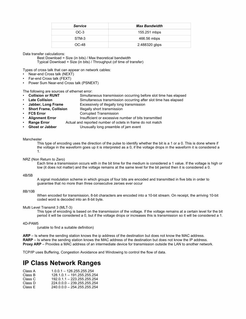
Service Max Bandwidth
OC-3 155.251 mbps
STM-3 466.56 mbps
OC-48 2.488320 gbps
Data transfer calculations:Best Download = Size (in bits) / Max theoretical bandwidthTypical Download = Size (in bits) / Throughput (of time of transfer)
Types of cross talk that can appear on network cables:• Near-end Cross talk (NEXT)• Far-end Cross talk (FEXT)• Power Sum Near-end Cross talk (PSNEXT)
The following are sources of ethernet error:• Collision or RUNT Simultaneous transmission occurring before slot time has elapsed• Late Collision Simultaneous transmission occurring after slot time has elapsed• Jabber, Long Frame Excessively of illegally long transmission• Short Frame, Collision Illegally short transmission• FCS Error Corrupted Transmission• Alignment Error Insufficient or excessive number of bits transmitted• Range Error Actual and reported number of octets in frame do not match• Ghost or Jabber Unusually long preamble of jam event
ManchesterThis type of encoding uses the direction of the pulse to identify whether the bit is a 1 or a 0. This is done where ifthe voltage in the waveform goes up it is interpreted as a 0, if the voltage drops in the waveform it is considered a1.
NRZ (Non Return to Zero)Each time a transmission occurs with in the bit time for the medium is considered a 1 value. If the voltage is high orlow (it does not matter) and the voltage remains at the same level for the bit period then it is considered a 0.
4B/5BA signal modulation scheme in which groups of four bits are encoded and transmitted in five bits in order toguarantee that no more than three consecutive zeroes ever occur
8B/10BWhen encoded for transmission, 8-bit characters are encoded into a 10-bit stream. On receipt, the arriving 10-bitcoded word is decoded into an 8-bit byte.
Multi Level Transmit 3 (MLT-3)This type of encoding is based on the transmission of the voltage. If the voltage remains at a certain level for the bitperiod it will be considered a 0, but if the voltage drops or increases this is transmission so it will be considered a 1.
4D-PAM5(unable to find a suitable definition)
ARP – Is where the sending station knows the ip address of the destination but does not know the MAC address.RARP – Is where the sending station knows the MAC address of the destination but does not know the IP address.Proxy ARP – Provides a MAC address of an intermediate device for transmission outside the LAN to another network.
TCP/IP uses Buffering, Congestion Avoidance and Windowing to control the flow of data.
IP Class Network RangesClass A 1.0.0.1 – 126.255.255.254Class B 128.1.0.1 – 191.255.255.254Class C 192.0.1.1 – 223.255.255.254Class D 224.0.0.0 – 239.255.255.254Class E 240.0.0.0 – 254.255.255.254

NOTE:.
• Class A address was designed to support very large networks with more than 16 million host address available, the firstbit of a class A address will always be a 0.
• Class B address was designed to support large networks. This first to bits of a class b address will always be a 10.• Class C address begin with 110• Class D address is 1110. This class is designed to handle multi casting ip addresses.• Class E addresses are reserved for the IETF for their research. Class addresses always begin with 11110.
The IP protocol is the most widely used protocol today. IP is a connectionless, unreliable, best effort delivery protocol, thismeans that there are no dedicated circuits that the protocol uses.
Depending on the routing protocol used sometimes the routers will keep ip addresses at their classful boundries. This isgood and bad, the main reason why this can be bad is if you are implementing a VLSM (discussed below) addressingscheme. The nature of VLSM allows ip's to go over certain classful boundries to be able to support the number of hostsrequired on networks. To force routing protocols to ignore the classfull boundries use the command “ip classless”.
Since IP is a connectionless best effort delivery system, IP does not handle errors or error messages. To overcome thisissue ICMP is used. ICMP has a varierty of uses to help contain the flow of packets in to a slow connection, these types ofpackets are called source quenching packets. ICMP is also used to deliver error messages such as host not found,destination network unreachable, etc. ICMP packets are also used in diagnosing network problems, there are two functionsof the IOS that use ICMP packets which are traceroute and ping, both of these functions send ICMP packets to thedestination ip address any errors along the way will generate ICMP packets informing the source of the packets of nature ofthe error.
Private Network IP Address RangesClass A 10.0.0.0 10.0.0.0/8Class B 172.16.0.0 – 172.31.0.0 172.16.0.0/12Class C 192.168.0.0 – 192.168.255.255 192.168.0.0/16
Binary Numbering and Hexadecimal numbersBinary numbers depend on the base 2 number system. Binary data is usually in block of 8 bits. Using 8 bits covers virtuallyall number and letter values. The binary representation of a number, a character or a symbol. EG
00110011 = 51 = 0x33 = “3”01101011 = 107 = 0x6B = “k”
Sample ASCII Chart:
0 1 2 3 4 5 6 7 8 9 A B C D E F0 NUL SOH STX ETX EOT ENQ ACK BEL BS HT LF VT FF CR SO SI1 DLE DC1 DC2 DC3 DC4 NAK SYN ETB CAN EM SUB ESC FS GS RS US2 SP ! " # $ % & ' ( ) * + , - . /3 0 1 2 3 4 5 6 7 8 9 : ; < = > ?4 @ A B C D E F G H I J K L M N O5 P Q R S T U V W X Y Z [ \ ] ^ _6 ` a b c d e f g h i j k l m n o7 p q r s t u v w x y z { | } ~ DEL
Convert a decimal number hexadecimal isn't as straight forward as you think, it is easier to convert the decimal number backto binary and then convert it to a hexadecimal from there. Below is a chart to enable you to convert a binary number to ahexadecimal number.
Binary Value Hex Value
0000 0
0001 1
0010 2
0011 3
0100 4

Binary Value Hex Value
0101 5
0110 6
0111 7
1000 8
1001 9
1010 A
1011 B
1100 C
1101 D
1110 E
1111 F
To make up the full hexadecimal number you need to convert all 8 bits of a binary number the chart above gives you theconversion to hex 4 bits at a time, to get the full hexadecimal representation just take the result of both 4 bit representationsand put them side by side to have the proper hexadecimal notation of any value. EG:
01100101 = 0x6510110011 = 0xB310011111 = 0x9F
Converting an ip to binary (to convert a number to binary going from left to right along the 8 bit numerical numbers“128,64,32,16,8,4,2,1” slowly add up the values that fall within the number in its current value until you sum up the numberwhich is required) below is couple of ip addresses converted to binary:
171.64.21.185 = 10101011.01000000.00010101.10111001192.168.16.1 = 11000000.10101000.00010000.00000001172.16.254.241 = 10101100.00010000.11111110.11110001
SubnettingIP addresses are a 32 bit number with a 32 bit subnet address mask. The decimal places are only there to make theaddress human readable. In order to work out address ranges in subnets the address is split into host and network portions.The network portion of the address is not changeable, the rest of the address is defined as the host portion which meansyou can allocate what ever address you want as long as it is with in the host address space. This is a classfull addressingscheme.
Eg:
192.168.16.1 = 11000000.10101000.00010000.00000001In this case the network is the 192.168 portion. To work out addressing you need to work out how many hosts need to besupported, so if you need to have n hosts you would use the formula n – 2 to know the total range so if you had to support 3networks with 50 hosts in each then 26 – 2 = 62 which is with in the required range. So the binary would look like this:
11000000.10101000.0001NNNN.NNHHHHHHnow we need to use 3 bits to create sub networks so the diagram will now look like:
11000000.10101000.0001NNNN.BBHHHHHHTo get the first and last ip's which will be your network address and broadcast address. The actual way of doing thisproperly is borrowing a set number of bits from the network portion to combine with the host portion. When you borrow bits itis important to remember that when you identfy the subnet mask, the bits you borrowed will always have their value set toone. This is necessary because if you do not include the borrowed bits in the subnet mask you will end up with a incorrect ipaddress and subnet mask definition which will result in an unstable network.
Eg:Assuming bits borrowed value is = 01

Network ID = 11000000.10101000.0001NNNN.01000000 = 192.168.16.64Broadcast = 11000000.10101000.0001NNNN.01111111 = 192.168.16.127IP Range = 192.168.16.65 to 192.168.16.126 (61 Host addresses)Subnet Mask = 255.255.255.192
NOTE: The network address is obtained by ANDing the subnet mask and the ip address together. Only like values willreveal the true network address. The last usable address is one minus the broadcast address, and the first usable networkaddress is one more than the network id address.
VLSM (Variable Length Subnet Mask)VLSM is similar to subnetting but there are no classfull limitations used, so you can have a 191.72.63.4/18 address and stillbe a valid ip. The important thing to remember with VLSM is that when allocating ip ranges that the addresses do notoverlap each other at a bitwise binary level. This can be checked by converting to binary. Point to Point links typically have a/30 mask on them. This is a classless addressing scheme. When determining ip ranges with VLSM you still need to havebits borrowed when splitting networks up. VLSM also allows you to use the first and last ip addresses within the range.
Eg: Point to Point link
172.16.254.241/30 = 10101100.00010000.11111110.11110001172.16.254.242/30 = 10101100.00010000.11111110.11110010Eg: Network
172.16.4.1/21 = 10101100.00010000.00000100.00000001
NOTE: Refer to the subnetting section to work out the ip ranges, network and broadcast addresses. (semester 3, 1.1.4) It isimportant to try and organize the addresses in such a way as that a summary address (or aggregate route) can be definedfor the entire network.
Another important aspect of VLSM is route summerization, this is important because a router can advertise a single routeout an interface for multiple routes. For example networks 192.168.98.0, 192.168.99.0 and 192.168.100.0 can berepresented by 192.168.96.0/20. Non contigenous networks can still be represented by a summary address, for example172.16.0.0, 172.16.2.0, 172.16.3.128 and 172.16.4.0 can be represented with 172.16.0.0/21.
Figuring out a summarized route by hand is a fairly simple process. Initially you should take all network id's available andconvert them to binary. Once in binary form start looking for all common bits between all the address. Then draw a linebetween the bits that dont change to the bits that do change, this is usually the route summerization point.
Obtaining IP AddressesThere are three ways of obtaining an ip address (bootp is not used anymore)1. BOOTP2. DHCP3. Manual Assignment
BOOTP only requires a single packet to exchange IP address information. Unlike RARP BOOTP packets include the IPaddress, router address (default gateway), server address and vendor specific information. The big drawback with thisprotocol is that it is not dynamic, meaning that the network administrator would have manually enter in the MAC address ofevery host that is going to connect to the network and assign an IP address against the MAC address. The transportprotocol used by BOOTP is udp.

DHCP uses dynamic address allocation to clients that request an IP address. Before DHCP will offer a IP to a client it tries toping the selected address twice, if both pings fail then the address is considered unused and will offer the address to theclient. DHCP does not have to have a MAC address table maintained in order for clients to be able to acquire an IP address.Because of the dynamic nature of DHCP a client can change from location to location with out having to have a profile setupat each location that the client is likely to connect to.
Routing protocol theoryPath determination is a layer three protocol function of the osi model. The network layer provides best-effort packet deliveryacross an inter-connected network. The router uses the network id of the destination network for the packet. Routers providetwo main functions which are path determination and packet switching.
NOTE: Routers separate BROADCAST and COLLISION domains. Routers also handle packets based on their destinationnetwork address (which is calculated from the destination host ip and the subnet mask provided in the header information).Routers also join multiple networks together. It basically allows for a packet from a 192.168.0.0 network that is destined for a172.16.0.0 network to get there by use of the default gateway (which is the ip of interface on the router).
Examples of routing protocols are: RIP, IGRP, EIGRP and OSPF the default transport protocol for all routing protocols isTCP/IP.
Setting a default route, inserts the ip address of the route into the routing table to provide the next hop service when thedestination ip is not in the routing table. When a router is weighing up which path to take when sending a packet to anetwork it uses the following metrics to decide:• Bandwidth• Delay• Load• Reliability• Hop Count• Ticks• Cost
Routing protocols fall into one of three categories:1. Distance Vector2. Link State3. Hybrid
Convergence is where all routers have the same knowledge of the network they are connected to. Routing loops can occurduring a slow convergence of the network.
Distance vector protocols do not maintain full network topology information. With distance vector protocol packets beingrouted contain a count field which increases with each hop through a router, if there are no counter measures the packet willkeep on routing forever. Hold down timers and hop counts are used to stop this. Some examples of distance vector basedrouting protocols are RIP and IGRP. Distance vector protocols do not keep full knowledge of the entire network. The routingtables for these protocols contain non-specific information about distant networks. These protocols also periodically sendout their entire routing table. For the RIP version 1 protocol the routing table update does not contain subnet masks as it is aclassful routing protocol.
Link State protocols maintain a full network topology database, when link state protocols initially startup they use LSApackets to discover the network topology, this discovery period uses a large amount of bandwidth. After the discovery hascompleted they use minimal bandwidth to keep topology tables accurate. Each time a link goes up or down a LSA (LinkState Advertisement) packet is sent. There are some concerns when it comes to the use of link state based routingalgrithms, the primary three are processor overhead, memory requirements and initial bandwidth consumption.
Some routed protocols that routers understand are:• TCP• UDP• PPP• Apple talk• IPX/SPX• Decnet• Banyan Vines• X.25• Frame Relay

• ISDN
• Static Routes – manually defined by the system admin• Default Route – manually defined by the system admin for the router to use when there is no other known route to the
destination.• Dynamic Routing – this is where the router uses the routing protocols to discover the destination networks.
Administrative distance is the rating of trust worthiness of the link. The number range is between 0 and 255. The higher thenumber the less likely certain protocols will not use the link.
Interior routing protocols are RIP, IGRP, EIGRP, BGP and OSPF. Routers use these protocols to share routing information.
This is the process that is used for path determination:• The destination address is obtained from the packet.• The mask of the first entry in the routing table is applied to the destination address.• The masked destination and the routing table entry are compared.• If there is a match, the packet is forwarded to the port that is associated with that table entry.• If there is no match, the next entry in the table is checked.• If the packet does not match any entries in the table, the router checks to see if a default route has been set.• If a default rout has been set, the packet is forwarded to the associated port. A default router is a route that is configured
by the network administrator as the route to use if there are no matches in the routing table.• If there is no default route, the packet is discarded. Usually a message is sent back to the sending device indicating that
the destination was unreachable.
Routing loops can occur when there is consistent routing information between the routers. This usually occurs on distancevector based networks as they are slow to detect changes in the network connections.
A routing loop is where at one point the network is stable and there are no latency problems. When a router goes offline,another router is still sending routing updates to other routers telling them that there still is a route there, then the otherrouters propogate this information but another router detects that the link is down and starts sending that information. In theend the routers get confused, so in order to prevent situations like these the distance vector algorithms use hold downtimers, hop count and a technique called split horizon (this is where routing information is not sent out the same interface itwas received on) to overcome these issues.
Trouble shooting routing1. When analyzing a network failure, make a clear problem statement2. Gather the facts needed to help isolate the possible causes3. Consider possible problems based on the facts the have been gathered4. Create an action plan based on the remaining potential problems.5. Implement the action plan, preforming each step carefully while testing to see whether the symptom disappears6. Analyze the results to determine whether the problem has been resolved. If it has, then the process is complete.7. If the problem has not been resolved, cerate an action plan based on the next most likely problem in the list. Return to
step 4 and repeat to this step until the problem is resolved.
WAN TechnologiesTODO Semester 4 chapter 2.2
Technology Frame Type
X.25 LAPB
ISDN LAPD,
LAPB (B-Channel transmission)
Modems LAPM
Frame Relay LAPF
Dialup Connections PPP
Routers (cisco default) HDLC
Standard HDLC does not support multiple protocols on a single link, since it has no field type in the frame to specify whatprotocol is contained in the frame. Cisco HDLC does support multiple protocols on the same link. HDLC is a layer 2 protocol.

HDLC has three different types of frames:
• Information Frames (I-Frames) – Carry the data to be transmitted for the station. Additional flow and error control –data may be pggy backed on an information frame.
• Supervisory Fram (S-Frames) – Provide request/response mechanisms when piggybacking is not used.• Unnumbered Frams (U-Frames) – Provide supplemental link control functions, such as connection setup. The code
field identifies the U-Frame type.
The default encapsulation for cisco routers is HDLC on synchronous lines. If the router is connected to a non cisco device itis better to use synchronous PPP.
Standard Description
EIA/TIA-232 Allows signal speeds of up to 64 kbps on a 25 pin d connector overshort distances. It was formerly known as rs-232. The ITU-T v.24specification is effectively the same.
EIA/TIA-449/530 A faster (up to 2 mbps) version of EIA/TIA-232. It uses a 36 pin Dconnector and is capable of longer cable runs. There are severalversion. Also known as RS-422 and RS-423.
EIA/TIA-612/613 The High Speed Serial Interface(HSSI), which provides access toservices up to 52 mbps on a 60 pin D connector.
V.35 An ITU-T standard for synchronous communications between a networkaccess device and a packet network at speeds up to 48 kbps. It uses a34 pin retangular connector.
X.21 An ITU-T standard for synchronous digital communications. It uses a 15pin D connector.
WAN Link Options:
ATM is a technology that is capable of transferring voice, video, and data through private and public networks. It is built on acell-based architecture rather than on a frame-based architecture. ATM cells are always a fixed length of 53 bytes. The 53byte ATM cell contains a 5 byte ATM header followed by 48 bytes of ATM payload. Small, fixed-length cells are well suitedfor carrying voice and video traffic because this traffic is intolerant of delay. Video and voice traffic do not have to wait for alarger data packet to be transmitted.
The 53 byte ATM cell is less efficient than the bigger frames and packets of Frame Relay and X.25. Furthermore, the ATMcell has at least 5 bytes of overhead for each 48-byte payload. When the cell is carrying segmented network layer packets,the overhead will be higher because the ATM switch must be able to reassemble the packets at the destination. A typicalATM line needs almost 20% greater bandwidth than Frame Relay to carry the same volume of network layer data.

Traffic Characteristics:
• Connectivity and volume flows• client / server data• connection or diagram oriention• latency tolerance, including length and variability• network availability• priority• error rate tolerance• priority• protocol type• average packet length
TCP/IP Suite Error and Control MessagesICMP is used for error notification. For example if a network attached to a router goes down and devices are sending data tothe device that has gone offline ICMP packets will be sent back to the senders of the data informing them that then device isunreachable. Sometimes the problem with the network can be quite severe and the ICMP packets could be adding to thecongestion that created the problem in the first place. Since ICMP can not generate anymore error messages it is possiblethat the end device may never know if there is a problem with the network at all.
Pinging a device generates ICMP messages directed to a specific device request and “echo request”. This is when thedestination device sends ICMP packets back to the source. If the pinged devices replies successfully it means that the enddevice can be reached via IP protocol.
Each packet has a set time to live or TTL before the packet will be dropped if its destination is too far away or it is beingrouted in a loop. In this case the sender will receive a ICMP back indicating that the packet has exceed its TTL value.
Some ICMP Message Types
Type ID Meaning
0 Echo Reply
3 Destination Unreachable
4 Source Quench
5 Redirect/Change Request
8 Echo Request
9 Router Advertisement
10 Router Selection
11 Time Exceeded
12 Parameter Problem
13 Timestamp Request
14 Timestamp Reply
15 Information Request
16 Information Reply
17 Address Mask Request
18 Address Mask Reply
ICMP must be part of all TCP/IP protocol suites, the reason for this is that IP does not guarentee the delivery of the packet

and it has no built in method to provide informational or control messages to the host. ICMP preforms these tasks for IP.
Router OpertaionUser Mode
allows you to view information but not make any changes to any of the settings
Privileged Modethis allows you to see more settings than “User Mode”, but also from this mode you can make changes. To enterthis mode type “enable” at the user mode prompt.
You can get out of privilaged mode by entering “disable”.
TIP: Entering “?” at any point in the command line brings up a list of sub commands or matching command list.
Terminal Configuration for the console interface9600 bps8 bits1 stop bitsno flow controlno parity
Boot sequence of a router:
1. The generic bootstrap loader in the ROM executes. The bootstrap is a simple set of instructions that tests hardware andinitializes the IOS for operation.
2. The IOS can be found in several places. The bootfield of the configuration register determines the location to be used inloading the IOS. If the bootfield indicates a flash or network load, boot system commands in the configuration file indicatethe exact name and location of the image.
3. The operating system image is loaded. When the IOS is loaded and operational, a listing of the available hardware andsoftware components is output to the console terminal screen.
4. The configuration file saved in NVRAM is loaded into main memory and executed one line at a time. The configurationcommands start routing processes, supply addresses for interfaces and define other operating characteristics of therouter.
5. If no valid configuration file exists in NVRAM, the operating system searches for an available TFTP server. If no TFTPserver exists the generic setup program is loaded. From there you can create a basic configuration for the router to use.
NOTE: The setup dialog can also be manually invoked from the command line. When it is manually loaded the defaultvalues that appear in the square brackets will be the current values from the active configuration.
Cursor Movement Keys:
Key Combination Description
Ctrl + A Moves to the beginning of the line
Ctrl + E Moves to the end of the line
Ctrl + F Moves forward one character
Ctrl + B Moves backward one character
Esc + F Moves forward one word

Key Combination Description
Esc + B Moves back one word
Ctrl + P Recalls previous command
NOTE: To disable enhanced editing type “terminal no editing”
TIP: To escape from dns, ping, etc commands use the key sequence <ctrl><shift><6> then <x>
To modify the number of items in the command history use the commands:history size <number>terminal history size <number>
The maximum number that can be used is 256
Basic commands:
show version displays boot image name,boot mode,boot rom version,routerup time, system image file and location, configuration register,router platform
show clock displays the current router time
show hosts displays the list of defined host names and addresses
show users shows directly connected users
show arp displays the arp table of the router
show running-config shows the current router configuration in memory
show startup-config shows the configuration that will be loaded when the routerstarts
show interfaces [status] shows information about all interfaces, such as line and protocolstate, ip address, interface specific statistics, line protocols, lineencapsulation (ppp, hdlc, etc)
show interfaces <interface> <id> will show interface specific information only such asencapsulation, lcp state, counters of runts / giants / rates /speed / reliability / packets / etc.
show cdp neighbors this lists all immediately connected routers/switches
show cdp neighbors detail shows more detailed information
show cdp entry <device name> displays the selected devices detailed information
show cdp interface lists update timers and protocol information
show ip route displays a list of all routes learned by the router
show ip interface brief shows summarized information about the interfaces on therouter, also what acl's are assigned and the direction they areassigned to.
show ip protocol Shows the details of the routing protocols in use by the router
show controllers serial <id> shows interface specific information about the hardware such ascable end and type, etc.
show flash Lists the contents of the flash device
undebug all Turns off all debugging commands
hostname <name> Sets the name of the router
line vty <start id> <end id> Allows you to set options for the vty terminals
enable password <password> Sets the user mode password
enable secret <password> Sets the privilaged mode password
banner motd #<message># Sets a message to display whenever anyone connects to therouter.

ip host <name> <host ip> [,<ip>,<ip>] Defines name to ip resolution locally from the router interfaceonly.
The command “show ip route” is probably the most important command that will ever be used in fault finding andconfiguration verification. Below is a sample output of what “show ip route” displays
Codes: C - Connected, S - static, I -IGRP, R - RIP, M - mobile, B - BGP D - EIGRP, EX - EIGRP external, O - OSPF, IA - OSPF inter area N1 - OSPF NSSA external type 1, N2 - OSPF NSSA external type 2 E1 - OSPF external type 1, E2 - OSPF external type 2, E - EGP i - IS-IS, L1 - IS-IS level1, L2 - IS-IS level 2, ia - IS-IS inter area * - candidate default, U - per-user static route, o - ODR P - periodic download statis routeGateway of last resort is not setC 192.168.4.0/24 is directly connected, Ethernet0 10.0.0.0/16 is subnetted, 3 subnetsC 10.3.0.0 is directly connected, Serial0C 10.4.0.0 is directly connected, Serial1C 10.5.0.0 is directly connected, Ethernet1This output shows that there are directly connected networks but there is no routing to other networks not on this router
Codes: C - Connected, S - static, I -IGRP, R - RIP, M - mobile, B - BGP D - EIGRP, EX - EIGRP external, O - OSPF, IA - OSPF inter area N1 - OSPF NSSA external type 1, N2 - OSPF NSSA external type 2 E1 - OSPF external type 1, E2 - OSPF external type 2, E - EGP i - IS-IS, L1 - IS-IS level1, L2 - IS-IS level 2, ia - IS-IS inter area * - candidate default, U - per-user static route, o - ODR P - periodic download statis routeGateway of last resort is not setI 192.168.30.0/24 [100/8986] via 192.168.0.2, 00:00:22, FastEthernet0/0 [100/10976] via 192.168.10.2, 00:00:22, Serial0/0C 192.168.10.0/24 is directly connected, Serial0/0I 192.168.20.0/24 [100/8486] via 192.168.0.2, 00:00:22, FastEthernet0/0 [100/10476] via 192.168.10.2, 00:00:22, Serial0/0C 192.168.0.0/24 is directly connected, FastEthernet0/0This output shows directly connected networks and networks available on another router through the IGRP protocol
Codes: C - Connected, S - static, I -IGRP, R - RIP, M - mobile, B - BGP D - EIGRP, EX - EIGRP external, O - OSPF, IA - OSPF inter area N1 - OSPF NSSA external type 1, N2 - OSPF NSSA external type 2 E1 - OSPF external type 1, E2 - OSPF external type 2, E - EGP i - IS-IS, L1 - IS-IS level1, L2 - IS-IS level 2, ia - IS-IS inter area * - candidate default, U - per-user static route, o - ODR P - periodic download statis routeGateway of last resort is not set 10.0.0.0/8 is variably subnetted, 2 subnets, 2 masksD 10.0.0.0/8 is a summary, 18:14:42, Null0C 10.0.1.0/25 is directly connected, Serial0/0R 192.168.40.0/24 [120/1] via 10.0.1.2, 00:00:10, Serial0/0 [120/1] via 172.16.0.1, 00:00:11, FastEthernet0/0I 192.168.32.0/24 [100/1600] via 172.16.0.1, 18:14:45, FastEthernet0/0D 192.168.56.0/24 [90/409600] via 172.16.0.1, 18:14:45, FastEthernet0/0D 192.168.47.0/24 [90/409600] via 172.16.0.1, 18:14:45, FastEthernet0/0R 192.168.48.0/24 [120/1] via 10.0.1.2, 00:00:16, Serial0/0 [120/1] via 172.16.0.1, 00:00:16, FastEthernet0/0

This output shows routes learned through IGRP, EIGRP, RIP and directly connected. In almost all of the examples there is aset of numbers in “[ ]” the first number 120, 100, 90 is the admin distance for those routes, the second number is the linecost, this is defined by a mathmatic calculation. The value for the line cost is dependant on the routing protocol in use.
To set the clock on the router:#clock set <time 24hr format> <date in Day Month Year eg 1 May 2004>#clock set 23:54:01 17 Mar 2004To disable all debugging commands:• no debug all• undebug allBasic Debug and Fault finding commands:• telnet• ping• traceroute• debug (using the sub commands)
Microsoft Utilities for network testing• NBTSTAT: displays windows netbios protocol information• NETSTAT: lists all active connections on the local computer• ARP: lists all the entries in the address resolution tables on the local computer• PING: sends ICMP echo's to a designated host to test connectivity• TRACERT: preforms a trace router process to the specified host
When pinging hosts on a router, the ping command uses ICMP packets to test the connectivity. When using this commandand you need to stop the ping sequence use the break out command <Ctrl>+<Shift>+6 to exit the process.
Configuring Router InterfacesSerial Interfaces. When configuring serial interfaces it is important to remember that if you are configuring a router that usinga directly connected serial line or it is the remote device that the clockrate always be set on the interface, otherwise noconnection could be made stable. The clocking signal is required for reliable stable communications. (besides the interfacewont even come up). Use the command “show controllers serial <interface id>” to identify the cable and set the clock rateaccordingly.
Basic config for a serial interface:config)#interface serial 0config-if)#ip address 172.16.4.1 255.255.255.192config-if)#clockrate 64000 (only if a dce device, must match line speed)config-if)#description Connected to another routerconfig-if)#no shutdownBasic config for a ethernet interfaceconfig)#interface ethernet 0config-if)#ip address 172.16.2.1 255.255.255.192config-if)#description This is connected to the LAN Level 4config-if)#no shutdownThe basic config for both interfaces is almost the same. This is also true when you start doing more advanced things likeauthentication between devices using ppp with chap, or ospf md5 encrypted updates between routers.
Setting descriptions is handy in large networks especially when you navigating around remotely and are un-sure of thenetwork layout.
NOTE: When pinging a host and the status shows the following sequence “.!.!.” then the most likely cause is a mis-configured ip address on the foreign router.
Router Boot Sequence1. Load the bootstrap program2. Load the operating system. If the IOS cannot be found in FLASH it will then go and look for a TFTP server to load the

IOS from, if a TFTP server is unavailable it will load the basic IOS from the ROM. The initial IOS location selection isbased on the REG value in the boot sequence
3. Displays a summary list of available components on the terminal screen.4. Looks in the NVRAM for the configuration file. If there is no config file located it will go and check the specified TFTP
location for the config file. If there is not config file located there it will begin the setup dialog process to configure therouter.
NOTE: The setup mode dialog can only be used to create a basic configuration. The setup dialog can be run even after avalid configuration has been loaded but the default values used will be the ones currently in use by the router. After any kindof change to the configuration and it is stable, it is always a good idea to do a “copy running-config startup-config” to makesure that if you loose power or the router is rebooted that the changes haven't been lost.
The “copy” command can be used to store the current configuration in memory to two places which are the “tftp” server and“startup-config”. To remove the startup configuration use the command “erase startup-config” this wipes the startupconfiguration from the NVRAM.
If you are trying to store the configuration file on to a TFTP server it will ask you for the following information host ip andfilename. The same information is required when retrieving a configuration file from a TFTP server, once you have retrieveda configuration file from the TFTP server you can load it into memory by using the following command “configure memory”
#copy running-config tftpRemote Host[]? <ip of tftp server> Name of configuration file to write to[<router name>-config]?<name of file>Write file <name of file> to <ip of tftp server> [confirm]? yes | noWriting <name of file> !!!!!!!!!!!!!!!!!!!!!!!!!!!!!!!!!!!!!!!!!!!!!!!!!!!!!!!!!!!!!!!!!!!!!!!!!!!!!!!!!!!!!!!!!!!!!!!!!!!!!!!!!!!!!!!!!!!!!!!!!!!!!!!!!!!!!!!!!!!!!!!!!!!!!!!!!!!!!!!!!!!!!!!!!!!!!!!!!! [OK]When configuring the router, an interface will only come up when there is a physical connection and the interface has beenconfigured correctly. If the line protocol does not come up then there is likely a configuration issue.
Password Recovery Procedure for 16xx/25xx routers1. Cold boot the router2. Press <Ctrl>+<Break> with in 60 seconds3. at the prompt type (for 25xx) “o/r 0x2142 or (for 16xx) “config 0x21424. type “I”5. type “N”6. now you will be at the prompt so enter into privileged mode “enable”7. “copy startup-config running-config”8. get into the configuration mode “configure terminal”9. set the new enable and secret passwords by “router(config)#enable password <password>” and “router(config)#enable
secret <password>”10. change the configuration register back to normal boot “router(config)#config register 0x2102”11. “end”12. “reload”
The only way to be able to recover a router like this is to be directly connected to the routers console interface with aconsole cable.
Router boot registers (for 25xx series routers):0x2142 – Password revocery boot mode.0x2102 – Normal boot mode.
Other things to note with configuration registers, is that when you want to change the setting of the register you shouldalways do a “show version” to get the current value of the boot register as you are only going to be modifing the last digit. Tochange the config register you need to issue the following command:
config)#config-register <hexadecimal value)config)#config-register 0x2102Below is a list of values to change of only the last digit in the hexadecimal value:• 0xnnn0 – Tells the router to use ROM monitor mode

• 0xnnn1 – Automatically boot from ROM (this is the default if the router has no flash memory)• 0xnnn2-0xnnnF – Examine NVRAM for boot system commands
Router boot optionsyou can configure where the router will look for an IOS image when the router boots up. The core command for this is “boot”under this command there are sub commands. EG:
config)#boot system tftp IOS_image 172.16.13.111config)#boot system flash romconfig)#boot system rom
IOS naming conventionsThe cisco IOS image filename has a naming convention that enables the administrator to quickly identify which router theIOS is for what the version number is, whether it is compressed or not. There is no definitive guide that is presented in thecourse so the note from the course will be used to help decipher part of the filenaming structure.
The filename “c2600-js-l_121-3.bin” means that this is for the 26xx series router “l” is uncompressed already (“mz” iscompressed) “121-3” is version 12.13and “js” is the feature set. There is additions to this, if there is a “k8” in the feature setportion of the filename then this means that there is less than or equal to 64 bit enryption on the IOS, but if this reads “k9”instead then there is greater than 64bit encryption.
TODO add disaster recovery maybe??TODO Possibly move the 3 sections below up into the networking topoligies and technologies
Structure of the TCP Segment:• Source port• Destination port• Sequence number• Acknowledgment Number• HLEN (Header length value)• Reserved• Code bits• Window• Checksum• Urgent Pointer• Data
Structure of the UDP Segment:• Source port• Destination port• Length• Checksum• Data

Protocols that use UDP are:• TFTP• SMNP• NFS• DNS
Port Numbers:
Port Protocol
21/20 FTP/FTP Data
22 SSH
23 Telnet
25 SMTP
53 DNS
67 BOOTP
68 BOOTS
69 TFTP
80 HTTP
110 POP3
119 NNTP
139 NetBIOS
161 SMNP
520 RIP
531 IRC
Ports 0 – 255 are reserved for public servicesPorts 256-1023 are reserved for additional (company) servicesPorts 1024 and above are un-regulated
provides name-to-ip resolution which enables you to refer to other outers by name instead of ip address. Use “show hosts”to display the list of define host names in the router.
config)#ip host <ip address> [, <ip address>, <ip address>]config)#ip host Melbourne 172.16.1.1 172.16.1.2 202.101.20.1Set the name of the routerconfig)#hostname <name>defines a server which provides dns like servicesconfig)#ip name-server <ip>enables dns lookup. Use “no” in front of the command to disable dns lookupconfig)#ip domain-lookupThis command defines a static route. Multiple static routes can be definedconfig)#ip route <ip address> <mask> <ip address/interface> <distance value>This command creates a default route entry that will be used when a packets destination is not known to the router.config)#ip default-network <ip address>Remember whenever you modify you configuration and the router is stable and operating as desired always backupthe configuration file to disk or TFTP server as a backup.
CDP (Cisco Discovery Protocol)CDP is protocol is used to identify directly connected devices to the router. CDP Version 1 is is running by default. This is alayer 2 protocol. CDP is media and protocol independent and runs on all cisco equipment. CDP Sends periodic messages to

updated information about other devices or itself, inside these messages there is a TTL field which indicates when theinformation should expire so the information the routers have is as up-to-date as possible.
#[no] cdp run#[no] cdp enableClear cdp information#clear cdp table#clear cdp countersUsing the command “show cdp neighbors detail” will show specific platform and IOS features of the specified device.
Show commands for cdp• show cdp (this will display current global settings for cdp)• show cdp neighbors [detail]• show cdp traffic• show cdp debugging• show cdp entry {<device name> [protocol | version]}Debug commands for cdp • debug cdp adjacency• debug cdp events• debug cdp ip• debug cdp packets
RIP (Routing Interior Protocol)RIP version 1 DOES NOT send the subnet mask in its routing updates where version 2 DOES send the subnet mask in itsrouting updates. RIP version 2 is a classless routing protocol. Both versions of RIP rely on hop count as their metric for pathdetermination. Both are based on distnace vector and do not take any other factors into consideration. RIPv1 broadcastsrouting updates, where as RIPv2 multi-casts its updates on 224.0.0.9. RIPv2 also allows authenticated updates.
Routing updates occur periodically (every 30 seconds by default) under RIP, with version 1 of rip each time an updateoccurs the entire routing table is sent. RIP uses UDP to exchange routing information. Routing updates are sent to otherdirectly connected routers only. If a router does not receive a routing update from a neighbour for 180 seconds the routerdetermines that there is a problem with the network and marks the route unreachable. If after 240 seconds the router stillhas not received an update the router removes the entry from its routing table. The default admin distance for rip is 120.
Since RIP is a distance vector based protocol it has a hop count limit of 16, if any packets that is routed through a rip basednetwork and the destination is more than 16 hops away the destination is considered unreachable. A route that has beendefined as a best path to a given network is inserted into the routing table. If multiple best paths are inserted into therouting table load balancing occurs.
If there is more than one path which has an equal cost then RIP will use a round robin approach where it will cycle throughall of the available parallel paths sending information. In bare bones terms it is load balancing. The max number ofsegments is 6.
Route poisoning is where the router detects that a particular network that is attached to is down, it adjusts the distance toone more than the maximum hop count allowed. Route poisoning is usually used with triggered updates, this greatincreases the convergance speed of a distance vector based network. Route poisoning does not break the split horizonrules. Split horizon states that network information cannot be received on the same interface that it was sent out on forspecific period. Triggered updates occur when the router detects a change in the routing table, when this happens itimmediately sends out a routing update to all directly connected neighbour routers. This triggered update will continue untilall routers connected to each other participating in the RIP network have received the change.
When the router receives an update through an interface it starts a timer, this is so that any updates received while the timeris operating the update received will be ignored. This helps to over come issues associated with slow convergance. If at anytime an update is received that contains routes with a poorer metric, the update is ignored. Ignoring an update with a poorermetric while the hold down timer is operating allows more time for the knowledge of a network outage to propogate throughthe entire network.
To enable rip version 1 or 2:config)#router rip [version 2]enable Version 2 of RIP (RIPv2 is classless , RIPv1 is classfull)

config-router)#version 2to enable triggered updates (this can only be done on serial links):config-if)#ip rip triggeredVersion 2 of rip can be enabled on a per interface basis. To configure an interface to receive RIP updates replace the “send”with “receive” the same applies for configuring an interface to receive both versions 1 and 2 of RIPconfig-if)#ip rip send version 2Both versions of rip can be sent through an interface by usingconfig-if)#ip rip send version 1 2to stop rip updates going out certain interfacesconfig-router)#passive-interface <interface id>to enable rip to operate across non-broadcast (unicast) networks such as frame relay use the command:config-router)#neighbor <ip address>To advertise networks using ripconfig-router)#network <network id>To distribute a static route that is not advertised with the “network” command. A static route is one that is defined by the “iproute” command:config-router)#redistribute staticRedistribute ospf routes in a rip networkconfig-router)#default-metric 10config-router)#redistribute ospf <process id>To enable split horizon on an interfaceconfig-if)#ip split-horizonDisable split horizon (per interface basis)config-if)#no ip split-horizonChange hold-down timer config-router)#timers basic update | invalid | holddown | flush <seconds>Change update timer config-router)#update-timer <seconds>Setting RIP Update Authenticationconfig-if)#ip rip authentication key-chain <name>config-if)#ip rip authentication mode text | md5NOTE: Sometimes there might be an in-compatibility between the different IOS's for md5 encrypted updates betweenneighbours.
NOTE: Whenever you modify a timer you must ensure that the other routers in the network have the same timer updatesapplied to them, otherwise the network may become unstable.
When using version 2 of rip (being a classless protocol) you may need to disable auto route summarization byconfig-router)#no auto-summaryThe best way to identify whether everything is working correctly is to issue the following commands:
#debug ip rip#clear ip route *The above commands will force all routes to be cleared and show each of the rip packets that contain the routing updates.Common problems with RIP:
• Using VLSM• Not enabling rip on ethernet interfaces• Forgetting about split horizon• ACL's

• handling of non-contigenous networks.
RIP version 1 cannot handle non-contigenous networks. If a network is not advertised then it may not be reachable either.Always ensure that network statements are correct for each router, all required interfaces are up, and ripv2 is not beingmixed incorrectly with ripv1.
RIP configuration checking and fault commands are:• show ip rip database• show ip protocols [summary]• show ip route• show ip interface brief• show running-config
• debug ip rip [events]
IGRP (Interior Gateway Protocol)Semester 2 Chapter 7.3
IGRP uses the following metrics to weigh up best path selection (this is configurable):
• Bandwidth – lowest bandwidth value• Load – load on the link towards the destination based on bits per second• Delay – cumulative interface delay along the path• Reliability – reliability on the link based on the exchange of keep alives sent.• MTU (Maximum Transmission Unit) – MTU of the path
IGRP is still based on a distance vector protocol. By default only Delay and bandwidth are used in the metric calculation, theother values can be taken into consideration by configuration only. Routing updates are by default every 90 seconds but thisvalue can be changed. IGRP has a maximum hop count of 255. IGRP uses the same techniques that RIP does to handlenetwork issues.
Routing update messages are sent every 90 seconds by default. The hold down timer is three times the value of theholddown timer plus 10 seconds which is 280 seconds. The default admin distance is 100.
IGRP advertisese three types of routes:
• Interior – routes between subnets of a network attached to the interface. If the network attached is not subnetted IGRPdoes not advertise the route.
• System – routes to networks with in an autonomous system.• Exterior – outside the autonomous system.
IGRP does not support vlsm.
To start igrp on a router:config)#router igrp <as number>to stop updated being sent out interfaces:config-router)#passive interface <interface id>To advertise a network:config-router)#network <ip address>Verifying IGRP opertion
• show interface [interface id]• show running-config• show ip protocols• show ip route
• debug ip igrp events• debug ip igrp transactions

• ping• traceroute
If IGRP is not working correctly check:
• check for problems at layer 1 and layer 2• autonomous network numbers are correct• no missing network statements or are incorrectly assigned• outgoing interface is setup correctly• the advertised network interface is up
OSPF (Open Shortest Path First)OSPF is a link state protocol, which uses Link State Advertisements (LSA) to identify when a network event has happened.OSPF maintaions full knowledge of the network and keeps a complete table listing of best paths to all known destinations onthe network. Initially when OSPF starts the entire network gets flooded with LSA's identifying all network components. Therouters use the information contained in these LSA's to build a topological database. Once this initial discovery process hascompleted the bandwidth usage is minimal. If a network event occurs then only a partial update is sent out, if no networkevents have occurred for a set period LSA's are sent to let the other routers know that it is still there. The default admindistance is 110.
Shortest path first calculations are based on the Dijkstra algorithm. Link state based algorithms such as this one overcomedistance limitions imposed by distance vectore based algorithms. Also link state based networks converge much faster thandistance vector based networks.
OSPF DR and BDR (if the DR fails) are the core of an OSPF network. When a DR receives a network event it will multi-castthe partial update on the 224.0.0.5 address which all other OSPF routers will pickup. HELLO packets are also multicast onthe 224.0.0.5 address, HELLO packets are by default sent every 10 seconds. On interfaces that are connected to NBMAand Frame Relay based networks the default is every 30 seconds. A HELLO packet carries information that all neighborsmust agree upon before forming an adjacency.
To enable OSPF on the router (providing the router IOS supports OSPF) use the command:config)#router ospf <process id>NOTE: Multiple ospf processes can be active in memory. But in practice only one process for OSPF is ever used. OSPFalso supports the use of VLSM. For this routing protocol it is always a good idea to define a local loopback interface toensure that OSPF remains stable.
When there is more than two routers in a network that is running OSPF there is a need to elect the DR and BDR. Thedefinition for a router to become the DR or BDR is the router id. The router id is the highest ip address on any physicalinterface. If there is a loopback address defined then the router id is based on the highest loopback interface ip address.Supposedly setting the priority of the OSPF at the interface should override the highest loopback address to force aparticular router to become the DR or BDR. A single router can be selected as the BDR for one network and the DR for adifferent network. If a router is added to the network the DR and BDR will retain their roles.
To advertise networks that is to be distributed through OSPF (the wildcard mask tells the router how many addresses it willsupport):config-router)#network <ip addr> <wilcard mask> area <area id>config-router)#network 172.16.4.0 0.0.0.255 area 0Redistribute static routesconfig-router)#default-information originateRedistribute rip routes

config-router)#redistribute rip subnetTo stop a interface participating in the routing topologyconfig-router)#passive-interface <interface> <number>Creating a local loopback interface:config)#interface loopback <number>config-if)#ip address <ip> <subnet mask>Setting the OSPF priority (this is done on the interface that is participating in OSPF):config-if)#ip ospf priority <number> (The default value for this is 1.)OSPF Cost Metric:config)#interface <interface> <number>config-if)#(1)bandwidth <value>config-if)#(2)ip ospf cost <value>1 the bandwidth value is required for ospf cost calculation, make sure that it matches the line speed2 this over-rides the default value of 1 with the specified value
To disable either of the two settings use the same command except with the no in front of it. EG:config-if)#no bandwidthconfig-if)#no ip ospf costDefault cost values that can be used are:
Line Speed Cost value Revise Value\
56 kbps modem 1785
T1 (1.544 mbps) 64
E1 (2.048 mbps) 48
4 mbps Token Ring 25
Ethernet 10
16 mbps Token Ring 6
10 mbps 100 100
100 mbps 1 19
1 gbps 1 4
10 gbps 1 2
Basic OSPF Authentication, passwords are sent as clear text. This is done on a per interface basis
config-if)#ip ospf authentication-key <password>config-if)#router ospf <process id>config-router)#area <area id> authenticationEncrypted OSPF Authentication.
config-if)#ip ospf message-digest-key <key id> md5 <key>config-if)#router ospf <process id>config-router)#area <area id> authentication message-digestExample encrypted OSPF authentication:config-if)#ip ospf message-digest-key 1 md5 asecretconfig-if)#exitconfig)#router ospf 1config-router)#area 0 authentication message-digestThe timers for hello and dead intervals are configured on a per interface basis. HELLO and DEAD intervals must be thesame on all routers in the OSPF network:
config-if)#ip ospf hello-interval <seconds>

config-if)#ip ospf dead-interval <seconds>Defining a default router in OSPF
config)#ip route <address> <mask> <destination address>config-if)#router ospf <process id>config-router)#default-information originateOSPF configuration checking and fault commands are:
Command Descriptionshow ip protocol Displays parameters about timers, filters, metrics, networks
and other information for the entire router.
show ip route Displays the routes known and how they were learned
show ip ospf interface <type> <number> Verfies that interfaces have been configured in the intendedareas. If no loopback address is specified the interface withthe highest address is take as the router ID. It also givestimer intervals including the hello interval and show theneighbor adjacencies.
show ip ospf [neighbor] [detail] Displays the details of neighbors, their priorities and state.
show ip interface brief Shows a summerized list of the interfaces
show ip ospf database Displays the contents of the topological databasemaintained by the router. The command also shows therouter ID and the ospf process ID.
Clear and Debug Commands:
Command Descriptionclear ip route * Clears all routes in the routing table
clear ip route a.b.c.d Clears a specific route out of the table. (a.b.c.d representsand network ip address. EG “clear ip route 172.16.4.0”)
debug ip ospf events Report all OSPF events
debug ip ospf adj Report OSPF Adjacency events
Ensure that all participating interfaces have the correct addresses, network statements have the correct wildcard masks andare in the correct area. Also check that hello and dead interval timers are correct across all routers. With authenticationmake sure the configuration on each routers participating in authenticated updates are correctly configured.
Use debugging commands to show the live process information:• debug ip ospf events• debug ip ospf packet • debug ip ospf adj
EIGRP (Enhanced Interior Gateway Protocol)EIGRP uses multiple metrics to decide which path the packet should take. The key factors for its metric calculation are:• bandwidth• load• delay• reliability
These factors are then feed into the DUAL (Diffused Update Algorithm) to calculate the shortest path to the destination. ForEIGRP to function properly a Autonomous System (AS) number has to be specified when the process is started. Only otherrouters that have the same AS number will updated correctly with each other. If there are other routers in the same networkbut have different AS numbers then those routers will not be part of the core network. The maximum hop count for EIGRP is224, this is still more than adequate to handle even the largest networks.
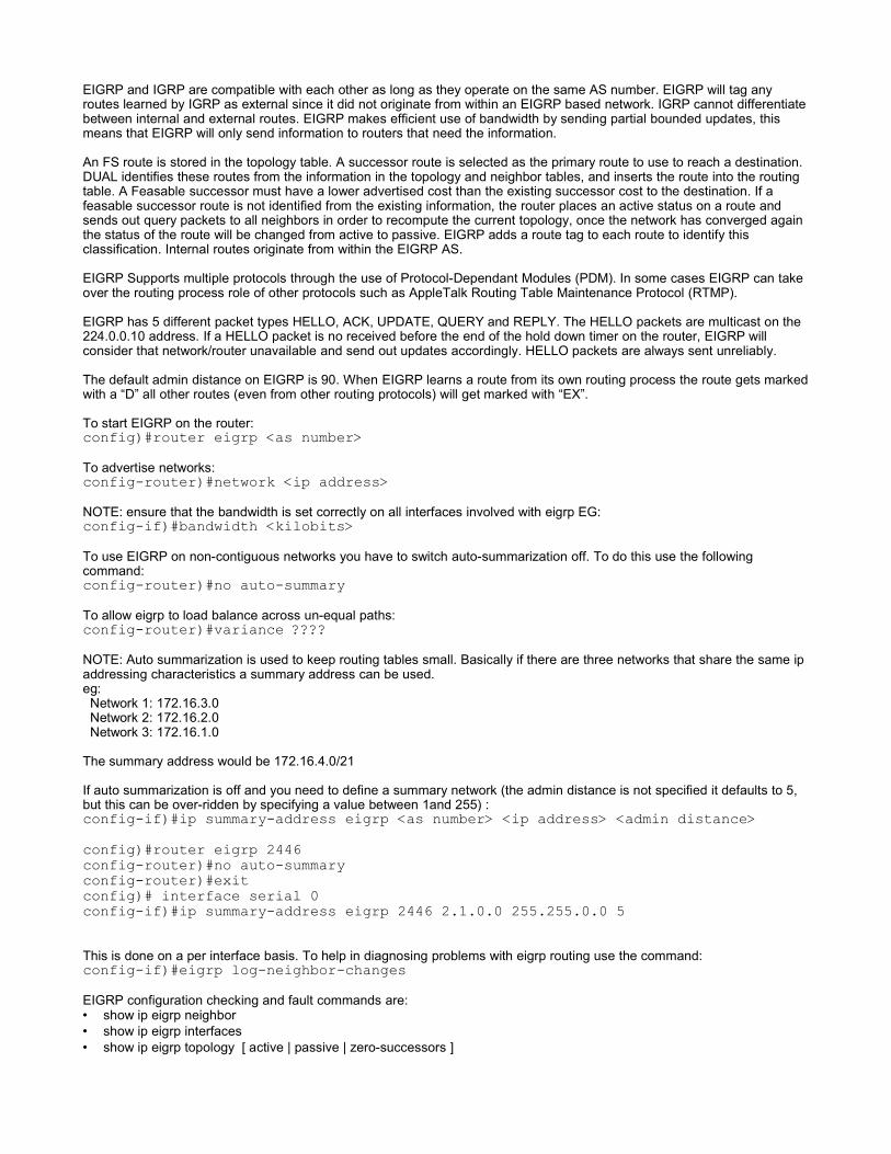
EIGRP and IGRP are compatible with each other as long as they operate on the same AS number. EIGRP will tag anyroutes learned by IGRP as external since it did not originate from within an EIGRP based network. IGRP cannot differentiatebetween internal and external routes. EIGRP makes efficient use of bandwidth by sending partial bounded updates, thismeans that EIGRP will only send information to routers that need the information.
An FS route is stored in the topology table. A successor route is selected as the primary route to use to reach a destination.DUAL identifies these routes from the information in the topology and neighbor tables, and inserts the route into the routingtable. A Feasable successor must have a lower advertised cost than the existing successor cost to the destination. If afeasable successor route is not identified from the existing information, the router places an active status on a route andsends out query packets to all neighbors in order to recompute the current topology, once the network has converged againthe status of the route will be changed from active to passive. EIGRP adds a route tag to each route to identify thisclassification. Internal routes originate from within the EIGRP AS.
EIGRP Supports multiple protocols through the use of Protocol-Dependant Modules (PDM). In some cases EIGRP can takeover the routing process role of other protocols such as AppleTalk Routing Table Maintenance Protocol (RTMP).
EIGRP has 5 different packet types HELLO, ACK, UPDATE, QUERY and REPLY. The HELLO packets are multicast on the224.0.0.10 address. If a HELLO packet is no received before the end of the hold down timer on the router, EIGRP willconsider that network/router unavailable and send out updates accordingly. HELLO packets are always sent unreliably.
The default admin distance on EIGRP is 90. When EIGRP learns a route from its own routing process the route gets markedwith a “D” all other routes (even from other routing protocols) will get marked with “EX”.
To start EIGRP on the router:config)#router eigrp <as number>To advertise networks:config-router)#network <ip address>NOTE: ensure that the bandwidth is set correctly on all interfaces involved with eigrp EG:config-if)#bandwidth <kilobits>To use EIGRP on non-contiguous networks you have to switch auto-summarization off. To do this use the followingcommand:config-router)#no auto-summaryTo allow eigrp to load balance across un-equal paths:config-router)#variance ????NOTE: Auto summarization is used to keep routing tables small. Basically if there are three networks that share the same ipaddressing characteristics a summary address can be used.eg: Network 1: 172.16.3.0 Network 2: 172.16.2.0 Network 3: 172.16.1.0
The summary address would be 172.16.4.0/21
If auto summarization is off and you need to define a summary network (the admin distance is not specified it defaults to 5,but this can be over-ridden by specifying a value between 1and 255) :config-if)#ip summary-address eigrp <as number> <ip address> <admin distance>config)#router eigrp 2446config-router)#no auto-summaryconfig-router)#exitconfig)# interface serial 0config-if)#ip summary-address eigrp 2446 2.1.0.0 255.255.0.0 5
This is done on a per interface basis. To help in diagnosing problems with eigrp routing use the command:config-if)#eigrp log-neighbor-changesEIGRP configuration checking and fault commands are:• show ip eigrp neighbor• show ip eigrp interfaces• show ip eigrp topology [ active | passive | zero-successors ]

• show ip eigrp traffic
• show ip interface brief• show ip route• show ip protocols
• debug eigrp fsm (shows the Feasible Successor activity• debug eigrp packet (shows packet activity)
Some possible reasons why EIGRP wont work properly:
• there are issues with layer 1 or layer 2• autonomous system numbers are incorrectly assigned• there may be congestion on the link or is possibly down• the outgoing interface is down• the advertised network is down• auto summerization is enabled on routers with non contigenous subnets• hold down timers maybe too long or too short (ensure that all timers are at the same value)
ACL (Access Control Lists)There are two types of ACL's standard and extended. Extended ACL's are placed closest to the destination of the definition,standard ones are placed closest to the source. Only one acl per interface, per direction, per protocol can be defined at anyone time. If traffic needs to be controlled in both directions then two ACL's must be defined, one for incoming traffic and onefor outgoing traffic. The only limit to the number of condition statements allowed in an ACL is only limited by the amount ofmemory on the router, if the ACL lists start getting too big ,management of those lists starts to become a problem.
There are certain acl numbers that are specified for certain functions:
1 – 99 Standard 100 – 199 Extended600 – 699 Apple talk800 – 899 IPX900 – 999 Extended IPX1000 – 1099 IPX Service Advertising Protocol
The order in which ACL's are defined is important cause if you have a complex condition at the start it may have anundesirable effect of denying the packet when it should get accepting it. When you are creating access lists, you cannot addor remove individual sections of it, so in order to add in an entry you have to remove the entire list and re-add the completelist again. By default there is a “deny any” condition at the end of any access list, it will still be there even if it is not defined,but it is always a good idea to define it.
Standard access lists are always placed closest to the destination, extended access lists should always be placed closest tothe source.
The command to define a standard acl is:config)#access-list <number> permit | deny [host] any | <ip address> [<subnet>]NOTE: the word “any” means 0.0.0.0
To remove any standard access list use the commandconfig)#no access-list <number>To define an extended acl is:config)#access-list <number> permit | deny <protocol> <source ip> <source mask><destination ip> eq <port>When defining what packets can and can't get through there are three types of comparison command eq (equals to), neq(not equals to), gt (greater than or equal to) and lt (less than or equal to).
The subnet mask of the source address must be a mirror of the address itself to define the allowable addresses. If thesubnet is defined as (1) then the subnet mask in the acl will be (2):

(1) 255.255.255.254 11111111.11111111.11111111.11111110(2) 0.0.0.1 00001010.00000000.00000000.00000001
To assign a access-list to an interfaceconfig-if)#ip access-group <access list id> in | out
An example of a standard ACL to allow traffic through from a specific network:config)#access-list 1 deny 172.16.1.1config)#access-list 1 permit 172.16.1.0 0.0.0.255config)#access-list 1 deny 172.16.0.0 0.0.255.255config)#access-list 1 permit 172.0.0.0 0.255.255.255config)#interface ethernet 0config-if)#ip access-group 1 inAn example of an ACL to allow only http traffic and not let other protocols through using an extended acl:
config)#access-list 101 permit ip 172.16.1.0 0.0.0.255 eq 80 | wwwconfig)#access-list 101 deny ip 192.168.192.0 0.0.0.255 eq 23 | telnetconfig)#access-list 101 deny ip any anyconfig)#interface ethernet | fastethernet 0config-if)#ip access-group 101 inTo remove an access list use the command:config)#no access-list <number>Named access lists have a little more flexibility that regular access lists, primarily because statements in the access list canbe deleted but new conditions can only be added to the end of the list. To create a named access list (NOTE: not compatiblewith IOS version 11.1 or earlier)config)#ip access-list extended | standard <name>config-ext-nacl)#permit <protocol> <source ip> host <dest ip> eq <port>To apply a named access list to an interface config-if)#ip access-group <access list name> in | out Named ACL example config)#ip access-list extended server-accessconfig-ext-nacl)#permit tcp any host 131.108.101.99 eq smtpconfig-ext-nacl)#permit tcp any host 131.108.101.99 eq wwwconfig-ext-nacl)#permit udp any host 131.108.101.99 eq domainconfig-ext-nacl)#deny ip any any logconfig-ext-nacl)#exitconfig)#interface fastethernet 0/0config-if)#ip access-group server-access out config-if)#endApplying a access list to a vty using a standard access list definitionconfig)#line vty 0 4config)#loginconfig)#password <password>config)#access-class <acl id> in | out
Checking commands:• show access-lists• show ip interface• show running-config
Configuring NAT and PATNAT and PAT were created to allow private IP's to access the internet through a single or multiple valid ip addresses. NATand PAT have two distinct advantages, it allows the entire internal addressing structure to change with out changing theconnectivity addressing or the connectivity addressing can be changed with out changin the entire internal addressing. NATalso allows many hosts to access the internet through one valid IP address.

• Inside Local Address – The IP adress assigned to a host on the inside network. The address is usually not a valid IPadress.
• Inside Global Address – A legitimate IP address assigned by the service provider that represents one or more localinside IP addresses that is seen by the internet
• Outside local address – The ip address of an outside host that is known to all inside hosts on the network• Outside Global Address – The IP address assigned to a host on the outside network. The own of the host assigns this
address.
NAT supports the following traffic types• ICMP• FTP• NetBIOS• RealNetworks RealAudio• WhitePines CUSeeMe• Xing Technologies Stream Works• DNS• H.323 Microsoft NetMeeting (IOS 12.0 and later)• VDONets VDOLive (IOS 11.3(4) or later)• VXtreams Web Theater (IOS 11.3(4) or later)• IP Multicast (IOS 12.0 or later)
NAT does not support:• Routing table updates• DNS zone transfers• BOOTP• talk and ntalk protocols• SNMP
The command “ip nat inside” or “ip nat outside” on the interface will define whether it is a inside global addressthat all devices on the private network will use, where as the outside definition will be the ip that is known for the network tothe rest of the world. Using the OVERLOAD key word at the end of the nat definition command causes PAT to be usedinstead of NAT. The draw back with using nat is the loss of end to end ip tracability.
Configure static NAT translation.config)#ip nat inside source static <local ip> <global ip>config)#interface <interface id>config-if)#ip nat inside | outsideTODO: Add natting example
To configure a range of addresses for NAT translationconfig)#ip nat pool <name> <start ip> <end ip> netmask <subnet mask>config)#ip nat inside | outside source list <list id> pool <name>e.g.:config)#access-list 1 permit 10.0.0.0 0.0.0.255config)#ip nat MyPool pool 10.0.0.1 10.0.0.255 netmask 0.0.0.255config)#ip nate inside source list 1 pool MyPool NAT can use access listsconfig)#access-list 1 permit 10.0.0.0 0.0.255.255config)#ip nat nat-pool pool 10.0.0.1 10.0.0.255 netmask 0.0.0.255config)#ip nat inside source list 1 pool nat-poolconfig)#ip nat inside source list 1 interface serial 0 overloadNOTE: Overloading an interface enables PAT.
Another way of implementing NAT with address poolconfig)#access-list 1 permit 10.0.0.0 0.0.255.255config)#ip name pool nat-pool-1 179.9.8.20 netmask 255.255.255.240config)#ip nat inside source list 1 pool nat-pool-1To remove dynamic source translation

config)#no ip nat inside sourceTo clear NAT/PAT tables#clear ip nat translationTo clear simple dynamic translation entry#clear ip nat translation inside <global ip> <local ip> [outside <local ip> <globalip>]To clear an extended dynamic translation entry#clear ip nat translation protocol inside <global ip> <global port> <local ip><local port> [outside <local ip> <local port> <global ip> <global port>
Example simple NAT config:
access-list 1 permit 192.168.1.0 0.0.0.255access-list 1 permit 192.168.2.0 0.0.0.255ip nat pool net-208 171.69.233.208 171.69.233.223 prefix-length 28ip nat inside source list 1 pool net-208interface ethernet 0 ip address 171.69.232.182 255.255.255.240 ip nat outsideinterface ethernet 1 ip address 192.168.1.94 255.255.255.0 ip nat inside
Checking commands• show ip nat translation [verbose]• show ip nat statistics
Configuring DHCP
This is the typical dhcp handshake between a client and a server.
• Client: DHCPDISCOVER• Server: DHCPOFFER

• Client: DHCPREQUEST• Server: DHCPACK• Client: If the client detects that the ip is in use a DHCPDECLINE is sent back to the server, the server will then make
another DHCPOFFER, this process will be repeated until the client agrees with the ip information sent.
Once the lease time for an ip address has elapsed or the client no longer needs the assigned ip address the client sends aDHCPRELEASE message back to the server. Before the DHCP sends the ip address requested by the client after theDHCPDISCOVER message has been received the server will ping the address twice (default) before sending the addressinformation to the client.
Syntaxconfig)#ip dhcp pool <pool name>dhcp-config)#network <ip> <mask> (this defines the ip address pool)To exclude specific addresses from the poolconfig)#ip dhcp excluded-address <ip> [<end ip address>]Some core options that should be set in large networksdhcp-config)#default-router <ip address>dhcp-config)#dns-server <ip address>dhcp-config)#netbios-name-server <ip address>dhcp-config)#domain-name <name (eg www.foo.com)>dhcp-config)#lease <days>,<hours>,<minutes> | infiniteTo disable dhcpconfig)#no service dhcpTo enable dhcpconfig)#service dhcpDHCP Relay, if the dhcp is beyond the current network the router connected to the other network can use the helper-address to relay dhcp requests and acknowledgments between the two networksconfig)#interface <interface id>config-if)#ip helper-address <ip address>NOTE: By default the IP HELPER-ADDRESS command forwards the following eight UDP services:• Time• TACACS• DNS• BOOTP/DHCP Server• BOOTP/DHCP Client• TFTP• NetBIOS Name Server• NetBIOS Datagram Service
Example DHCP configuration:config)#ip dhcp excluded-address 172.16.1.1 172.16.1.5config)#ip dhcp pool my-dhcp-pooldhcp-config)#network 172.16.1.0 255.255.255.0dhcp-config)#default-router 172.16.1.1dhcp-config)#dns-server 172.16.1.2dhcp-config)#domain-name foo.bar.comdhcp-config)#lease 0,24,0Checking commands• show ip dhcp binding (lists all assigned ip addresses)• show ip dhcp server statistics
• debug ip dhcp server events
Configuring PPPPPP can be configured over multiple types of physical interfaces:

• Asynchronous Serial• Synchronous Serial• HSSI• ISDN
PPP uses the Line Control Protocol (LCP) to negotiate and setup control options on the link. LCP sits on top of the physicallayer and is used to establish, configure and test the data link connection. Network Control Protocol (NCP) is used toencapsulate and negotiate multiple network layer protocols.
PPP also uses LCP to automatically agree upon encpasulation format options such as:
• Authentication – Authentication options require that the calling side of the link enter information to help ensure thecaller has the network administrators permission to make the call. Peer routers exchange authentication messages. Twoauthentication choices are PAP and CHAP.
• Compression – Compression options increase the effective bandwidth throguhput on PP connections by reducing theamount of data in the frame that must travel across the link. The two compression protocols available are stacker andpredictor.
• Error Detection – Error detection mechanisms with PPP enable a process to identify fault conditions. The Quality andMagic numbers options help ensure a reliable, loop-free data link.
• Multilink – Cisco IOS release 11.1 and later supports multilink PPP. This alternative provides load balancing over therouter interfaces that PPP uses.
• PPP Callback – To further enhance security, PPP offers callback over PPP. With this option a cisco router can act as acallback client or as a callback server. The client makes the initial call, requests that it be called back, and terminates itscall. The callback router answers the call and makes the return call based on configuration statements.
The fields of a PPP frame are:• Flag - 01111110• Address - 11111111• Control Type – 1 byte that is usually 00000011• Protocol – 2 byte code that identifies the protocol encapsulated in the data field of the frame• Data – 0 or more bytes that contain the datagram for the protocol specified. (max length is 1500 bytes)• FCS – 2 byte field that contains a checksum of the entire packet. Error control.
PPP permits multiple network layer protocols to operate on the same communications link. For every network layer protocolused, a seperate Network Control Protocol (NCP) is provided. PPP establishes a session by setting up optional parametersby using LCP (Link Control Protocol) after this phase has been completed the NCP (Network Control Protocol) takes over.
PAP should really not be used as an authentication option across links as it sends passwords as clear text, meaning thatany one with a packet sniffer can view the packet and extract the password used. Where as CHAP uses encrypted (usuallymd5 enncryption) authentication, meaning that the password used is based on an encryption algorithm, CHAP also uses arandom challenge authentication which is where the two hosts are continually authenticating each other at random intervals.CHAP is a three way repeated authentication process where as PAP is a two way.
Whenever two routers try to authenticate against each other the username and paswords must be known to each router.The password that would normally be used in authentication is the enable password on the router. Other passwords can besetup.
To enable PPP (this is typically done over serial links, this is also the bare minimum to enable ppp between interfaces)config-if)#encapsulation pppNOTE: When connecting to non-cisco routers ppp should be used, if you are connecting to another cisco router then leave

the default encapsulation which is hdlc.
To setup additional usernames and passwords. The username supplied must match the remote router name and enablepassword.config)#username <username> password <password>Using CHAP over PPPNOTE: This must match the other routers username/hostname and password information
config)#username <name> password <password> config)#interface <interface id> (normal serial interface)config-if)#ppp authentication pap | chap | pap chapIf using PAP or PAP CHAP option, must also configure PAP user information byconfig-if)#ppp pap sent-username <username> password <password>Setting compressionconfig-if)#compress stac | predictorSetting Line Quality before dropping the link config-if)#ppp quality <percentage 1-100>Enabling multi-link over ppp (load balancing)config-if)#ppp multilinkChecking commands
Command Descriptionshow interface <interface> <port id>
Debugging Commnads:Command Description
debug ppp tasksdebug serial interface Verifies whether hdlc keep alive packets are incrementing
debug arp Show information about or learning about routes.
debug frame-relay lmi Obtains Local management Interface information whish isuseful for determining whether a frame relay switch aresending and receiving LMI packets.
debug frame-relay events Determines whether exchanges are occuring between arouter and a frame relay switch.
debug ppp negotiation | authentication |packet | error | chap
Shows point to point packets transmitted during PPP startupwhere PPP options are negotiated
debug ppp packet Shows PPP packets being sent and received
debug ppp Shows PPP errors such as illegal or malformed framesassociated with a PPP connection.
debug ppp authentication Shows PPP CHAP and PAP exchanges.
Configuring ISDNTelephone companies developed ISDN as part of an effort to standardize subscriber services. This included the User-Network Interface (UNI), better known as the local loop. The ISDN standards define the hardware and call setup schemesfor end-to-end digital connectivity. These standards help achieve the goal of worldwide connectivity by ensuring that ISDNnetworks easily communicate with one another. In an ISDN network, the digitizing function is done at the user site rather

than the telephone company.
ISDN brings digital connectivity to local sites. The following list provides some of the benefits of ISDN:
• Carries a variety of user traffic signals, including data, voice, and video • Offers much faster call setup than modem connections • B channels provide a faster data transfer rate than modems • B channels are suitable for negotiated Point-to-Point Protocol (PPP) links
ISDN uses out of band signaling, the delta channel or D-Channel is used for call setup /tear down and signaling. Each ISDNB-Channel or bearer channel can make a seperate serial connection to any other site in the ISDN network. ISDN isconsidered a circuit-switched connection.
An NT1 device is normally required in the US but if the BRI port is labelled “BRI U” then there is no requirement for anyadditional hardware to connect the line to the router. A BRI interface labelled “BRI S/T” does not have an integrated NT1device so the NT1 device is required for ISDN connectivity. BRI frames are 48 bits in length, 4000 frames are transmittedevery second. In ISDN BRI the delta channel only uses 16 kpbs bandwidth and the B channels are 64 kpbs. PRI D-Channels transmit speed is up to 64kbps. ISDN B-Channels carry information using either HDLC or PPP as the layer 2protocol. The D-Channel uses LAPD (Link Access Procedure on the D-Channel) to transmit information to the destination.
Digital Signal Level Speed T Designation No Channels
DS0 64 kbps - 1
DS1 1.544 mbps T1 24
DS2 6.312 mbps T2 96
DS3 44.736 mbps T3 672
DS4 274.176 mbps T4 4032
• E Protocols – Recommend telephone network standards for ISDN• I Protocols – Deals with concepts, terminology and general methods.
• I-100 – General IDSN Concepts• I-200 – Service Aspects• I-300 – Network Aspects• I-400 – How UNI is provided (User Network Interface)
• Q Protocols – Cover switching and signalling
NOTE: If you try to insert a cable that is connected to a non-ISDN device into the BRI port you will seriously damage thenon-ISDN device.
Q.921 = LAPD, PPP, HDLC (layer 2)Q.931 = ISDN Network layer between the terminal and switch. (layer 3, IP). This implements call setup, signalling and tear
down, and control calls on B-Channels.I.430 = Basic ISDN rate interface (Layer 1)I.431 = Primary ISDN rate interface (Layer 1)
ISDN Reference Points:• R – References the connection between a non-ISDN compatible device terminal equipment type 2 (TE2) and a termianl
adapter (TA), for example an RS-232 serial interface.• S – References the points that connect into the customer switching device network termination type 2 (NT2) and enables
calls between the various types of customer premises equipment.• T – Electrically identical to the S interface, it references the outbound connection from the NT2 to the ISDN network of
the Network Termination type 1 (NT1)• U – References the connection between the NT1 and the ISDN network ownder by the telephone company.

Both the S and T references are electrically similay, some interfaces are labelled S/T interface. Although they preformdifferent functions, the port is electrically the same and can be used for either function. In the US the customer is expectedto provide the NT1, in europe and other various countries the telephone company provides the NT1 function and presentsan S/T interface to the customer. In this circumstance the customer is not required to supply a seperate NT1 or integratedNT1 function in the terminal device. If the NT1 is CPE, make sure the router has a U interface. If the router has an S/Tinterface, then it will need an external NT1 to connect to the ISDN provider. If the router has a connector labeled BRI then itis already ISDN-enabled. With a native ISDN interface already built in, the router is a TE1. If the router has a U interface, italso has a built-in NT1.
Specifying the switch type config)#isdn switch-type <switch type>To configure the encapsulation on the bri/pri interfaceconfig-if)encapsulation ppp | lapb | hdlc | x25 | cppNOTE: This can be set globally or per interface. There are various switch types that are defined (eg. basic-ni, primary-5ess,primary-dms100, primary-ni, etc)
For interfaces that will be connected to the isdn SPID's must be defined. Below is how to configure SPID's for BRI config-if)isdn spid1 <spid identifier> [LDN]config-if)isdn spid2 <spid identifier> [LDN]To disable the ISDN switch type (this can be defined globally or per interface)config)isdn switch-type noneExample basic configuration for BRI ISDNconfig)#isdn switch-type basic-niconfig)#isdn bri 0config-if)#isdn spid1 51055540000001 5554000config-if)#isdn spid2 51055540010001 5554001NOTE: when ever you change a spid it may be necessary to reset the connection between the router and the ISDN switch.This can be done by issuing the command “clear interface bri”.
Switch Type Location
primary-5ess USA
primary-dms100 North America
primary-ni North America
primary-net5 UK, Europe, Australia
primary-ntt Japan
Configure Primary ISDNconfig)#isdn switch-type <switch-type>config)#controller e1 | t1 <interface>config-controller)#framing sf | esf | crc4 | no-crc4config-controller)#linecode ami | b8zs | hdb3config-controller)#pri-group [timeslots <range (in hours)>]config-controller)#interface serial <interface>:<d-channel id>Example T1 Configuration on isdnconfig)#controller t1 0

config-controller)#framing esfconfig-controller)#linecode b8zsconfig-controller)#pri-group timeslots 1-24config-controller)#interface serial 3/0:23config-if)#isdn switch-type primary-5essconfig-if)#no cdp enable
Example E1 Configurationconfig)#controller e1 0config-controller)#framing crc4config-controller)#linecode hdb3config-controller)#pri-group timeslots 1-24config-controller)#interface serial 3/0:15config-if)#isdn switch-type primary-net5config-if)#no cdp enable Within an E1 or T1 facility, the channels start numbering at 1. The numbering ranges from 1 to 31 for E1 and 1 to 24 for T1.Serial interfaces in the Cisco router start numbering at 0. Therefore, channel 16, the E1 signaling channel, is channel 15 onthe interface. Channel 24, the T1 signaling channel, becomes channel 23 on the interface. Thus, interface serial 0/0:23refers to the D channel of a T1 PRI.
Checking commandsCommand Description
show isdn status Shows the status of layer 1,2 and 3 as well as the spid information.Switch type
show isdn active Shows the current call information, charging units used during thecall, whether call charging information is provided during calls or atthe end of the call
show isdn interface bri <interface id>[:<channel id>] This shows channel specific information. It shows the encapsulationtype being used, protocols active (ip, cdpcp, etc)
show dialer Displays current call status, dial up timer values, dial reason and theremote device that is connected.
Command Descriptiondebug isdn q931 shows call setup and tear down and call control messages
debug isdn q921 shows layer 2 d-channel messages – use this command isshow isdn status does not show any error when there is
debug ppp authentication Displays ppp authentication messages including CHAP andPAP packets.
debug ppp negotiation Displays ppp traffic and exchanges while ppp componentsare negotiated.
debug ppp error Displays protocol errors and error statistics associated witha ppp connection. Use debug ppp commands totroubleshoot Layer 2 problems if the “show isdn status”command does not indicate an isdn problem.
clear interface bri <port>[:<channel>] resets current isdn connections on the interface and resetsthe interface connected to the isdn switch. This issometimes necessary when the spid1 / spid2 have beenchanged

Legacy DDR ConfigurationDDR (Dial on Demand Routing) it used to control the amount of traffic that goes out through the ISDN connection. DDR canbe setup to allow all traffic through the connection or limit it to ftp, telnet or http traffic only or only from certain hosts with in anetwork. It is recommended that static routes be setup to prevent constant activation of the DDR link. The key to efficeintDDR operation is in the definition of interesting traffic. Interesting traffic is defined with a dialer list. Dialer lists can allow alltraffic from a specific protocol to bring up a DDR link, or they can quert an access list to see what specific types of trafficshould bring up the link. Dialer lists do not filter traffic on an interface. Even traffic that is not interesting will be forwarded ifthe connection to the destination is active.
Once a connection is established a idle timer starts as soon as interesting and un-interesting traffic has stoppedtransmitting. The timer will reset again if more traffic goes in or comes out of the link. Once the idle timer expires the link willbe closed and will not open again until interesting traffics comes through again.
To configure legacy DDR perform the following steps:• Define static routes (ip route – remember by default static routes will take priority over dynamic routes, if you have
many static routes defined you should consider using a summerized or default static route)• Specify interesting traffic (access control lists)• Configure the dialer information
To create a dialer list config)#dialer-list <group no> protocol <protocol> permit | deny | list
<access list id>EG (let any ip protocol through)config)#dialer-list 1 protocol ip permitUsing an access list with Legacy DDR (do not allow ftp or telnet traffic allow everything else)config)#access-list 101 deny tcp any any eq ftpconfig)#access-list 101 dent tcp any any eq telnetconfig)#access-list 101 permit ip any anyconfig)#dialer-list 1 protocol ip list 101Configuring dialer mapsconfig)#dialer-list 1 protocol ip permitconfig)#username <username> password <password>config)#interface bri <port> config-if)#ip address <ip> <mask>config-if)#encapsulation ppp (always recommended)config-if)#dialer map ip <next hop ip> [name <username>] [speed 56 | 64]
[broadcast] <phone number>config-if)#dialer-group <group id>config-if)#ppp authentication chap (always recommended)NOTE: both the usernames specified must match exactly as this is also case sensitive
E.G.:config)#ip route 10.10.0.0 255.255.0.0 10.1.0.2config)#ip route 10.20.0.0 255.255.0.0 10.1.0.2config)#dialer-list 1 protocol ip permitconfig)#username Central password ciscoconfig)#interface bri 0config-if)#ip address 10.1.0.1 255.255.255.0config-if)#encapsulation pppconfig-if)#dialer idle-timeout 180config-if)#dialer map ip 10.1.0.2 name Central 5552000config-if)#dialer-group 1config-if)#ppp authentication chap
Specify a timeoutconfig-if)#dialer idle-timeout <seconds>To force the router to dial an ISDN number use the command:#isdn call interface [<isdn number>]

Dialer Profiles allows interfaces to take on different characteristics based on the type of call being made, unlike legacy DDRwhere the interface is bound to the type of call, interfaces are allocated dynamically depending on the call type. Each dialerinterface is the complete configuration for a destination.
config)#interface dialer<id>config-if)#ip address <ip> <mask>config-if)#encapsulation pppconfig-if)#dialer remote-name little-userconfig-if)#dialer string 5554000config-if)#dialer pool <pool num>config-if)#dialer-group <group num>config-if)#ppp authentication chapconfig-if)#endconfig)#interface bri <port>config-if)#encapsulation pppconfig-if)#dialer pool-member <pool num> priority <num>config-if)#ppp authentication chapNOTE: the router will use the lowest the priority interfaces in the dialer pool first. Dialer profiles can configure each B-channel with a different IP and subnet, as well as different encapsulations.
If a interface is continuously going up and down when it should not be the most likely cause will be routing updates or keepalive messages. If the router is not connecting when it should, then it is possible that an ISDN problem is the cause and notthe DDR configuration, use the command “isdn call interface” command to forcethe local router to attempt to dial into theremote router.
This command will detail the trafiic and its source of the packets that keep making ISDN calls. If the router is not connectingto the ISDN switch when it should be one of the most likely causes of the problem is the ISDN/ISDN Network itself and notDDR.
CommandsCommand Description
show dialer [ interface [ bri ] ] Displays information in the same format as the legacy DDR statisticson incoming and outgoing calls.
show isdn active Shows information about the current ISDN calls
show isdn status Displays information about the three layers of the BRI interface
clear interface bri Clears any currently connected calls and resets the interface with theISDN switch. This command forces the router to renegotiate itsSPIDs with the switch. This is necessary after making changes with“isdn spid1” and “isdn spid2” commands.
Debug commandsCommand Description
debug isdn q.921 Shows ISDN call setup exchanges. The “i=” field int eh q.921 payloadfield is the hexadecimal value of a Q.931 message.
The seventh and eigth most significant hexadecimal numbers in the “i=”field indicate the type of q.931 message.
• 0x05 – call setup
• 0x02 – call proceeding message
• 0x07 – call connect message
• 0x0F – call ack message
debug isdn q.931 Observe calls setup exchanges for both outgoing and incoming calls
debug dialer [ events | packets ] Troubleshoot DDR connectivity. The events option will show when acall is initiated and what traffic caused the call to be placed.
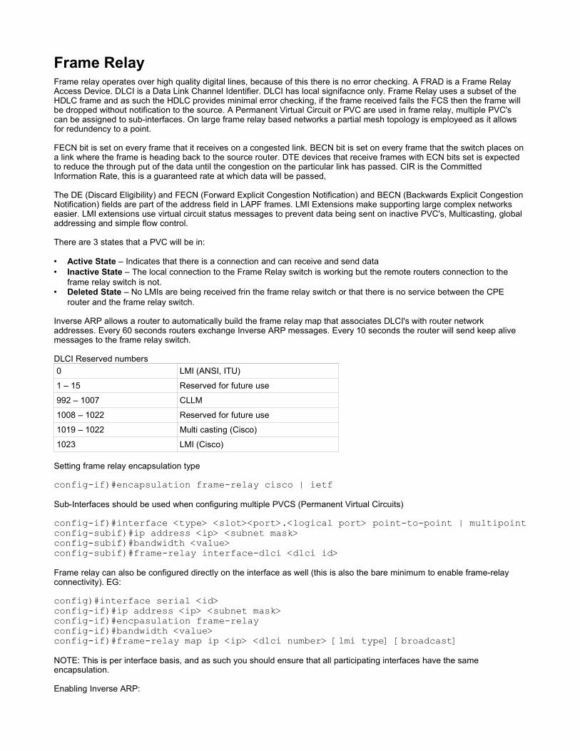
Frame RelayFrame relay operates over high quality digital lines, because of this there is no error checking. A FRAD is a Frame RelayAccess Device. DLCI is a Data Link Channel Identifier. DLCI has local signifacnce only. Frame Relay uses a subset of theHDLC frame and as such the HDLC provides minimal error checking, if the frame received fails the FCS then the frame willbe dropped without notification to the source. A Permanent Virtual Circuit or PVC are used in frame relay, multiple PVC'scan be assigned to sub-interfaces. On large frame relay based networks a partial mesh topology is employeed as it allowsfor redundency to a point.
FECN bit is set on every frame that it receives on a congested link. BECN bit is set on every frame that the switch places ona link where the frame is heading back to the source router. DTE devices that receive frames with ECN bits set is expectedto reduce the through put of the data until the congestion on the particular link has passed. CIR is the CommittedInformation Rate, this is a guaranteed rate at which data will be passed,
The DE (Discard Eligibility) and FECN (Forward Explicit Congestion Notification) and BECN (Backwards Explicit CongestionNotification) fields are part of the address field in LAPF frames. LMI Extensions make supporting large complex networkseasier. LMI extensions use virtual circuit status messages to prevent data being sent on inactive PVC's, Multicasting, globaladdressing and simple flow control.
There are 3 states that a PVC will be in:
• Active State – Indicates that there is a connection and can receive and send data• Inactive State – The local connection to the Frame Relay switch is working but the remote routers connection to the
frame relay switch is not.• Deleted State – No LMIs are being received frin the frame relay switch or that there is no service between the CPE
router and the frame relay switch.
Inverse ARP allows a router to automatically build the frame relay map that associates DLCI's with router networkaddresses. Every 60 seconds routers exchange Inverse ARP messages. Every 10 seconds the router will send keep alivemessages to the frame relay switch.
DLCI Reserved numbers0 LMI (ANSI, ITU)
1 – 15 Reserved for future use
992 – 1007 CLLM
1008 – 1022 Reserved for future use
1019 – 1022 Multi casting (Cisco)
1023 LMI (Cisco)
Setting frame relay encapsulation type
config-if)#encapsulation frame-relay cisco | ietfSub-Interfaces should be used when configuring multiple PVCS (Permanent Virtual Circuits)
config-if)#interface <type> <slot><port>.<logical port> point-to-point | multipointconfig-subif)#ip address <ip> <subnet mask>config-subif)#bandwidth <value>config-subif)#frame-relay interface-dlci <dlci id>Frame relay can also be configured directly on the interface as well (this is also the bare minimum to enable frame-relayconnectivity). EG:
config)#interface serial <id>config-if)#ip address <ip> <subnet mask>config-if)#encpasulation frame-relayconfig-if)#bandwidth <value>config-if)#frame-relay map ip <ip> <dlci number> [lmi type] [broadcast]NOTE: This is per interface basis, and as such you should ensure that all participating interfaces have the sameencapsulation.
Enabling Inverse ARP:
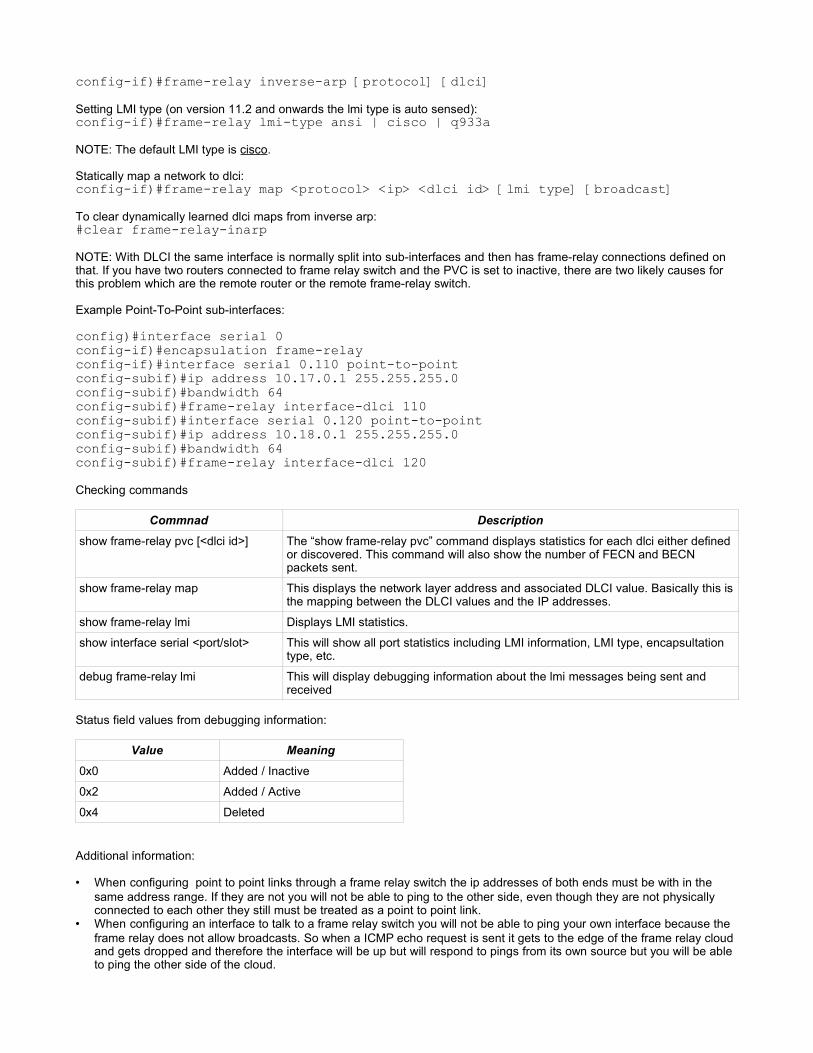
config-if)#frame-relay inverse-arp [protocol] [dlci]Setting LMI type (on version 11.2 and onwards the lmi type is auto sensed):config-if)#frame-relay lmi-type ansi | cisco | q933aNOTE: The default LMI type is cisco.
Statically map a network to dlci:config-if)#frame-relay map <protocol> <ip> <dlci id> [lmi type] [broadcast]To clear dynamically learned dlci maps from inverse arp:#clear frame-relay-inarpNOTE: With DLCI the same interface is normally split into sub-interfaces and then has frame-relay connections defined onthat. If you have two routers connected to frame relay switch and the PVC is set to inactive, there are two likely causes forthis problem which are the remote router or the remote frame-relay switch.
Example Point-To-Point sub-interfaces:
config)#interface serial 0config-if)#encapsulation frame-relayconfig-if)#interface serial 0.110 point-to-pointconfig-subif)#ip address 10.17.0.1 255.255.255.0config-subif)#bandwidth 64config-subif)#frame-relay interface-dlci 110config-subif)#interface serial 0.120 point-to-pointconfig-subif)#ip address 10.18.0.1 255.255.255.0config-subif)#bandwidth 64config-subif)#frame-relay interface-dlci 120Checking commands
Commnad Description
show frame-relay pvc [<dlci id>] The “show frame-relay pvc” command displays statistics for each dlci either definedor discovered. This command will also show the number of FECN and BECNpackets sent.
show frame-relay map This displays the network layer address and associated DLCI value. Basically this isthe mapping between the DLCI values and the IP addresses.
show frame-relay lmi Displays LMI statistics.
show interface serial <port/slot> This will show all port statistics including LMI information, LMI type, encapsultationtype, etc.
debug frame-relay lmi This will display debugging information about the lmi messages being sent andreceived
Status field values from debugging information:
Value Meaning
0x0 Added / Inactive
0x2 Added / Active
0x4 Deleted
Additional information:
• When configuring point to point links through a frame relay switch the ip addresses of both ends must be with in thesame address range. If they are not you will not be able to ping to the other side, even though they are not physicallyconnected to each other they still must be treated as a point to point link.
• When configuring an interface to talk to a frame relay switch you will not be able to ping your own interface because theframe relay does not allow broadcasts. So when a ICMP echo request is sent it gets to the edge of the frame relay cloudand gets dropped and therefore the interface will be up but will respond to pings from its own source but you will be ableto ping the other side of the cloud.

Switch ConfigurationLED State Meaning
Stat Off No link
On Link
Flashing Data activity
Flashing green and orange Link fault
Solid Amber Disabled or blocked
UH LED On high bandwidth usage
Off bandwidth usage is low
FDUP On full duplex
Off half duplex
100 On port speed is 100 mbps
Off port speed is 10 mbps
System Off If the switch is on then the POS is running
On POST was succesfull
Amber POST failed
Terminal Configuration settings
9600 bps8 data bits1 stop bitno flow control
Basic checking commandsCommand Description
show version Gives the version information for the software and hardware.
show running-config Displays the current switch configuration
show interface [status] Displays the administrative and operational status of a switchingport.
show controllers ethernet-controller Gives port statistic errors, dropped frames, deferred frames,collisions, etc.
show post Indicates whether the switch passed the POST or not.
show vlan Displays current vlan database entries.
show flash Lists the files stored in the flash device (typically IOS name, vlanconfiguration, startup config)
show mac-address-table Lists all learned mac addresses from network devices attached tothe switch
show port security This lists the type of security on the port and what is set to happenif the security flags are triggered
When Switches (and bridges) first start up, their switching tables are empty. The switch will automatically learn the macaddress of all attached devices when they send data through the switched that is destined for another device on a differentport on the switch. Every MAC address learned is stored in the CAM (Content Addressable Memory) table, but thisinformation is lost either when the timeout for the entry has elapsed or the switch has lost power. For any switch that needsto be managed remotely an ip address known as the management ip must be set on the switch.
NOTE: Switches EXTEND broadcast domains but SEPARATE COLLISION domains. Each port on a switch is considered a

separate collision domain. The default time that HELLO packets are sent out is 2 seconds.
Switches have three modes of operation.1. Store and Forward (this has the most latency, as it buffers the entire packet before switching it out the destination port)2. Cut Through ( this just reads up to the destination address of the packet and begins switching the packet immediately.
Both the sending and receiving ports must be operating at the same speed). There are two forms of cut through whichare:
• Fast Forward (reads the first 64 bytes of a frame – just enough to read the destination information. If a frame isless than this length it is invalid and will be dropped)
• Fragment free (filters out collission fragments before fowarding begins, collission fragments must be smallerthan 64 bytes. If it is more than 64 bytes it is considered a valid packet)
Because of the inherit nature of the switch (switching is done at the hardware level) it makes it impossible to make a packetdivert from its intended destination port. Asymmetric switching allows connections of unlike bandwidth to be able to stillcommunicate, when a slower host is receiving data from a faster host through the switch, the switch will buffer the data fromthe faster connection and send it out at the slower rate for the receiving host.
Set the name of the switch:config)#hostname <name>Setting default gatewayconfig)#ip default-gateway <ip address> <mask>Configure a ip for the VLANconfig)#interface vlan <vlan id>config-if)#ip address <ip address> <mask>Configure static mac addressesconfig)#mac-address-table static <address> interface fastethernet <port id> vlan<vlan id>EG:config)#mac-address-table static 0010.7a60.1884 interface fastEthernet 0/5 vlan 1NOTE: To remove a specific configured entry in the mac-address-table use the same command as above but have the word“no” in front of it
Switch configuration can be backed up to a tftp like routers#copy running-config tftpTo remove a defined mac address use the word “no” in front of the mac-addresses-table command. If the switch has beenset to dynamically learn NIC MAC addresses and you need to clear the list use the command:#clear mac-address-tableOn 1900 catalyst switches to set full duplex mode:#duplex fullList defined mac addresses:#show mac-address-tablePort Security is defined on a per port basisconfig)#interface fastEthernet <port no>config-if)#port security action | max-mac-countif the Action option is specified there are two additional settings that can be passed which are:config-if)#port security action shutdownorconfig-if)#port security action trapNOTE: just by entering “port security” will enable it with default values. If shutdown is specified the the port is shutdownwhen the security conditions are met. If trap is specified then an snmp trap is set indicating a security violation.
Password recovery for a switch:• turn the switch off • turn it back on holding the mode button until the led on port 1 is off

• “flash-init”• “load-helper”• rename the config.text file by “rename flash:config.text flash:config.old”• “boot”• cancel out of the configuration dialog when it is presented• rename the config file back to its original name “rename flash:config.old flash:config.text”• “enable”• get the config into memory “copy flash:config.text system:running-config”• disable the secret password “no enable secret”• set the new password “enable secret <new password>”• save the config in memory to startup “copy running-config startup-config”• reboot the switch
Checking and debug commands• show flash• show boot• show mac-address-table• show port security
Spanning Tree ProtocolFor every switched network the following elements exist:• One root bridge per network• One root port per non root bridge • One designated port per segment • Unused, non-designated ports
This is enabled by default and normally doesn't need to be changed. Each port on a switch using this protocol will be in oneof five states• Blocking (default 20 seconds)• Listening (default 15 seconds)• Learning (default 15 seconds)• Forwarding• Disabled
When the spanning tree protocol is initializing on a port, the port will go through the following steps:1. initializing2. blocking receives BPDU's only3. listening building active topology4. learning building bridging table. Data packets are dropped, but MAC addresses are learned.5. forwarding sending and receiving data6. disabled administratively down (usually happens when there is a switching loop or has been shutdown by
configuration)

Switches send messages to each other called Bridge Protocol Data Units (BPDU), these messgaes are processed by theswitch, the switch uses the information contained in these messages to form logical loop free switching paths. BPDU'scontain enough information for the switches to do the following:
• Select a single switch that will act as the root of the spanning tree• calculate the shortest path from itself to the root switch• Designate one of the switches as the closest one to the root for each lan segment (the designated switch handles all
communication from the lan to the root bridge)• choose one of its ports as its root port, for each non-root swtich. This is the interface that gibes the best path to the root
switch• select ports that are part of the spanning tree, the designated ports. Non-designated ports are blocked.
The end result depending on what the port detects during these six stages will depend on whether it will forward data or bein a blocking mode to prevent switching loops.
TODO: Describe how the switch calculates the spanning tree cost of a link.
The default Bridge ID (BID) value is set to 32768 by default when the switch is turned on, the actual BID value is based onthe MAC address as well as the priority value. This value can be altered to define which switch will become the root of thespanning tree. The smaller the BID value the higher its prority of becoming the root switch. The BPDU's are sent out everytwo seconds. The swtich with the lowest ID becomes the root switch for the network.
You can alter the priority of the spanning tree protocol on the switch by:config)#spanning-tree priority <value>for IOS version 12.0 or newer:config)#spanning-tree vlan <vlan id> priority <value>Changing hello-time intervals:config)#spanning-tree vlan <vlan id> hello-time <seconds>Changing forward-time intervalsconfig)#spanning-tree vlan <vlan id> forward-time <seconds>Changing maximum vlan age before reconfiguringconfig)#spanning-tree vlan <vlan id> max-age <seconds>8.3.4 gives a description of the output from the “show spanning-tree” output.
to check the status of spanning tree protocol:• show spanning-tree [brief]• show interface vlan <vlan id>• show vlan
Creating VLANS VLANs allow the network administrator to organize devices on the network into logical groups even though they can bephysically seperated between floors, buildings, etc. VLAN's are transparent to the client machine, there is no specialconfiguration or hardware modifications required for this. VLAN's also increase security, for example you can have a groupof people need access to certain machines (which are on the same VLAN) and other users will not be able to contact thesemachines because they are on a different VLAN. VLAN's also seperate broadcast domains. To enable communicationbetween VLAN's a router is required (this is explained how in the next section)
There are three basic types of VLANs:
• Port based • MAC address based• Protocol based
The frame headers are encapsulated or modifed to reflect the VLAN ID before the frame is sent over the link betweenswitches. Before the frame is sent to the destination device the frame header is reverted back to its original form. There aretwo major methods of frame tagging, Inter-Switch Link ISL and 802.1q. ISL used to be the standard but it is being replacedwith 802.1q frame tagging. Using ISL to communicate between VLAN's extend the size of an ethernet frame.

The vlan database is stored in the flash memory of the switch with the file name vlan.dat)switch#vlan databaseswitch(vlan)#vlan <vlan no> name <name of vlan>switch(vlan)#vlan 2 name VLAN2_ACCOUNTSTo assign a vlan id to an interface:switch(config)#interface fastEthernet <interface id> switch(config-if)#switchport mode accessswitch(config-if)#switchport access vlan <vlan id>swtich(config-if)#switchport access vlan 2To remove a vlan from the database:switch(config-if)#no switchport access vlan <vlan id>switch(config-if)#exitswitch#vlan databaseswitch(vlan)#no vlan <vlan id>NOTE: the no command must be applied to all interfaces active in the vlan that is being removed. VLAN1 cannot beremoved as this is the default management VLAN.
The entire vlan database can be removed by executing the command:switch#delete flash:vlan.dat
Checking commands:• show interface vlan <vlan id>• show vlan id <vlan id>• show vlan name <vlan name>• show vlan [brief]
• debug sw-vlan packets
Trunking with VLANSThis is done on a per port basis. This specifies which ports will allow traffic to flow upstream:switch(config-if)#switchport mode trunkswitch(config-if)#switchport trunk encapsulation dot1q | 8021q or islNOTE: ISL is not supported on catalyst 2950 switches. Also you must not setup an ip address on the physical interface, ifyou do this then trunking cannot be enabled on the sub-interfaces.
To configure a router to accept trunking between devices (many sub interfaces can be defined on one interface)config)#interface <interface id>.<sub interface id>router(config-subif)#encapsulation dot1q <vlan id>router(config-subif)#ip address <ip> <mask>NOTE: Do not start configuring the interface as normal, because if you make a mistake you have to drop the entire interfaceconfiguration. In order for this to work correctly all routers and switches connected to the trunk must use the sameencapsulation. You must also set the ip of the sub-interface to match the ip addressing used in the specified VLAN.
Checking commands:
• show port capabilities (helps the admin to determine whether the port supports trunking or not)• show trunk • show interface fastethernet <port id> switchport
VTP ConfigurationVTP typically operates in one of three modes:
• Server• Client

• Transparent
VTP Servers have the ability to create, modify and remove vlans from the main vlan database. VTP Clients cannot create,modify or delete entries from their VLAN databases. Switches that operate in VTP transparent mode forward VTPinformation but themselves ignore the information. A transparent switch will not modify its database when updates arereceived nor will the switch send out an updated indicating a change in its VLAN, changes made to the VLAN configurationon the transparent switch have local significance only. VTP swtiches in transparent mode will only forward advertisements.
When a switch operating in VTP receives an update to the VLAN information it checks for a revision number that isassociated with every updated and compares it to its current version number stored in the VLAN database. If the versionnumber is higher than the one currently store the switch accepts the update as it is considered more accurate than what itcurrent has. The switch will store the changes in its VLAN database and update the version number to the one that isindicated in the update. Each time a change is made on the VTP server. VTP Configurations are flooded out the entiredomain every five minutes. To reset a VLAN database revision number to 0 the switch must be rebooted, because erasestartup-config will not do this.
Management domains by default are in non-secure mode. As soon as you set a password the switch goes into securemode, for all switches that are connected in the vtp domain the same password must be set the same.
To view the status of the current VLAN configuration use the command:#show vtp statusWill give the following output:
VTP Version : 2Configuration Revision : 2Maximum VLANS supported locally : 68Number of existing VLANs : 6VTP Operating Mode : ClientVTP Domain Name : CiscoVTP Pruning Mode : DisabledVTP V2 Mode : EnabledVTP Traps Generation : DisabledMD5 Digest : 0x35 0x84 0x7B 0x04 0x3D 0x55 0x3B 0xDAConfiguration Last modified by 0.0.0.0 at 12-23-02 20:24:33To show vtp packet and activity statistics:#show vtp statisticsIf vtp is set for version 2 then all other switches in participating in vtp must also use the same version#vlan databasevlan)#vtp v2-modeTo create a domainvlan)#vtp domain <domain name>To specify the switches role in vtpvlan)#vtp server | client | transparentNOTE: if a switch has been set to “transparent” and the domain name information matches that from the server. The localvlan information in the startup files are used instead. While in transparent mode the switch will still forward vtp updates tothe rest of the switches, changes to the VLAN configuration will not be passed on to other switches.
Checking commands• show vtp status | counters
SNMP (Simple Network Management Protocol)SNMP operates on the Application layer. An SNMP managed network consists of the following three key components:
• Network Management System (NMS) – NMS executes applications that monitor and control managed devices. Thebulk of the processing and memory resources required for network management are provided by NMS. One or moreNMS's must exist on any managed network.

• Managed Devices – Are network nodes that contain an SNMP agent that reside on a managed network. Manageddevices collect and store management information and make this information available to NMS's using SNMP. Manageddevices, sometimes called network elements can be routers, access servers, switches, bridges, hubs, computers orprinters.
• Agents – Are network management software modules that reside in managed devices. An agent has local knowledge ofmanagement information and translates that information into a form compatible with SNMP.
OSI have defined a model for Network management:Area Description
Organization Describes key components of network management and their relationships.Depending on the standards, this can represent different types of architecture
Information Concerned with structure and storage of information. Representation of objects andinformation relevant to their management. The ISO defined the structure ofmanagement information (SMI) to define the syntax and semantics of managementinformation stored in the MIB
Communication How the management data is communicated between the agent and the managerprocess. Transport medium of the message exchange(transport protocol). Messageformat of communication (application protocol). Actual message (commands andresponses)
Functional Addresses the network management applications that reside upon the NMS. OSImodel categorizes five areas of function, sometimes referred to as the FCAPS.
• Fault
• Configuration
• Accounting
• Performance
• Security
Simple SNMP has three basic message types that are used to communicate with SNMP based devices these messagesare:
• GetRequest • GetNextRequest• SetRequest
A SNMP trap enables the device to send a message to the management station indicating that an event which requiresattention to has occurred.
For SNMPv2c and above the same message types mentioned above are used with one extra type defined• GetBulkRequest
The GetBulkRequest message sends more than one message per transmission unlike simple SNMP where it only sent onetype of information per packet, this resulted in in-efficient transfers. The GetBulkRequest address this problem. SNMP usesUDP as the core transport protocol. SNMP has no provisions to cope with lost or late packets. Each SNMP messagecontains a community string, this string is basically a security place holder until SNMPv2 was released.

All SNMP based management applications have to be configured to use the appropriate community strings. When settingcommunity strings you can specify either read only or read-write access. Multiple community strings can be set. The defaultvalues for community strings are “public” for read-only and “private” for read-write access.
To set a community string on a router:config)#snmp-server community <string> ro | rwTo set additional information about a device that will be retrieved via snmpconfig)#snmp-server location <text>config)#snmp-server contact <text>
SyslogOn every cisco router there is a syslog function that allows the logging of events that match a certain criteria. There are eightdifferent types of events that are defined:
0. Emergencies1. Alerts2. Critical3. Errors4. Warnings5. Notifications6. Informational7. Debugging
To enable loggingconfig)#logging onTo set a level for loggingconfig)#logging trap <log type name [informational, alerts, critical, etc]>The information reported by the logging sub-system can be sent to another system by specifying a host name or ip address:config)#logging <hostname> | <ip address>Timestamps can be added to every log messageconfig)#service timestamps log datetimeWhen setting a level of information to log, all message types up to and including the one specified will be logged, not justthe level specified.

AcronymsARP Address Resolution Protocol
AS Autonomous System
ATM Asynchronous Transfer Mode
BDR Backup Designated Router
CSMA/CD Collision Sense Multi Access/Collision Detection
CSMA/CA Collision Sense Multi Access/Collision Avoidance
CDP Cisco Discovery Protocol
CIDR Classes Inter-Domain Routing
CO Central Office
DCE Data Communications Equipment
DR Designated Router
DTE Data Terminal Equipment
EMI Electromagnetic Interference
HDLC High-Level Data Link Control
HSSI High Speed Serial Interface
ISL Inter Switch Link
LANE LAN Emulation
LASER Light Amplification by Stimulated Emission Radiation
LDN Local-dial Directory Number
MAC Media Access Control
MAN Metropolitan Area Network
MTU Maximum Transmission Unit
NAT Network Address Translation protocol
NBMA Non-Broadcast Multi-Access
NIC Network Information Center
Network Interface Card
PAT Port Address Translation protocol
POST Power On Self Test
POTS Plain Old Telephone System
RARP Reverse Address Resolution Protocol
RFI Radio Frequency Interference
STP Spanning Tree Protocol
TDM Time Division Multiplexing
TDR Time Domain Reflectometry
VINES Virtual Integrated Network Service
VTP Virtual Terminal Protocol
VLAN Trunking Protocol
WINS Windows Internet Naming Service: Microsoft's own implementation of DNS

Protocols
802.11 Wireless Wireless LAN, 1-2 mbps rating
802.11a Wireless 11 mbps rating
802.11b Wireless
802.11g Wireless 54 mbps rating
802.12 Demand Priority
802.14 Cable TV
802.15 Wireless Wireless Personal Area Network
802.1d Spanning Tree Protocol
802.1q Fast Ethernet
FDDI
IEEE Defined ethernet VLAN protocol. Frame Tagging. Modifiedheaders
Semester 3 Chapter 8.1.5 Figure 6
802.1w Rapid Spanning Tree Protocol
802.2 Ethernet Covers 10Base2, 10Base5, 10BaseT, 10BaseF, 100BaseTX,100baseFX, 1000BaseT
802.3 Ethernet Specification for 10mbps ethernet
802.3u (Fast) Ethernet Specifications for 100mbps fast ethernet
802.3z (Gigabit) Ethernet Specifications for 1000mbps gigabit ethernet
802.4 Token Token Passing Bus
802.5 Token Token Ring
802.6 DQDB DQDB Access Method
802.9 Integrated Services
ISL Fast Ethernet ISL Header encapsulates the LAN frame and there is a VLAN ID inthe header. The frame is lengthened by this
LANE ATM No additional tagging