Orthographic Projection Lesson Revised
87
Orthographic & Isometric Drawing Lesson Technological Design Mr. Wadowski
-
Upload
victor-m-morcillo -
Category
Documents
-
view
66 -
download
7
description
tle
Transcript of Orthographic Projection Lesson Revised

Orthographic &
Isometric
Drawing Lesson
Technological Design
Mr. Wadowski
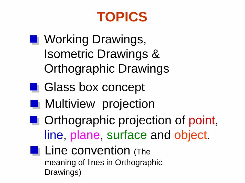
TOPICS
Glass box concept
Line convention (The
meaning of lines in Orthographic
Drawings)
Orthographic projection of point,
line, plane, surface and object.
Working Drawings,
Isometric Drawings &
Orthographic Drawings
Multiview projection
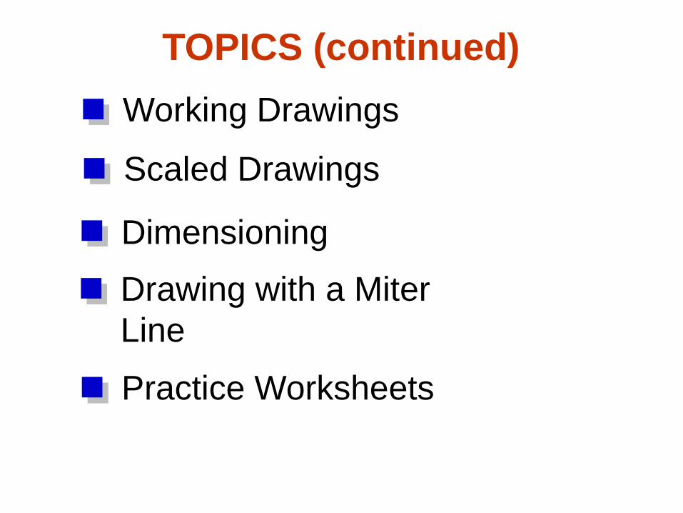
TOPICS (continued)
Drawing with a Miter
Line
Dimensioning
Working Drawings
Scaled Drawings
Practice Worksheets
Working Drawings
The final stage of illustrating your
solution is to prepare a set of
technical illustrations called
Working Drawings.
This set of drawings contains all
the information needed to build
the product.

Orthographic Drawings
Used to show details of the front, top and right side views
Uses 3 views
Used to provide dimensions and special shapes by using
different line types. For example object, hidden, and center
lines.
Draw the front first, top second, and right side last
Space the views out equally at 40 mm
A miter line is used to project details of the object from the top
view to the right side view without measuring. Drawn
at 45 degrees.

ISOMETRIC Drawings
Three dimensional (3d)
You can see how all three views fit together
All horizontal lines are angled at 30 degrees
and vertical lines remain vertical
Hidden lines and dimensioning are not shown
on Isometric drawings

Orthographic and Isometric
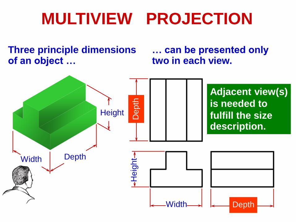
MULTIVIEW PROJECTION
Three principle dimensionsof an object …
Width Depth
Height
Width
He
igh
t
Depth
Dep
th
… can be presented onlytwo in each view.
Adjacent view(s)
is needed to
fulfill the sizedescription.

1. Revolve the object with respect
to observer.
TO OBTAIN MULTIVIEW
REPRESENTATION OF AN OBJECT
2. The observer moves around the
object.
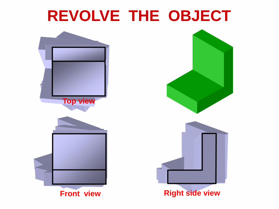
REVOLVE THE OBJECT
Front view Right side view
Top view

OBSERVER MOVE AROUND
Front view Right side view
Top view
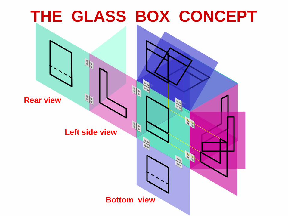
THE GLASS BOX CONCEPT
Bottom view
Left side view
Rear view

Height
Width
Dep
th
History

Orthographic
Projection
of Object Features

OBJECT FEATURES
Edges are lines that represent the boundary
between two faces.
Corners Represent the intersection of two or
more edges.
Edge
Corner
Edge No edge
No corner No corner
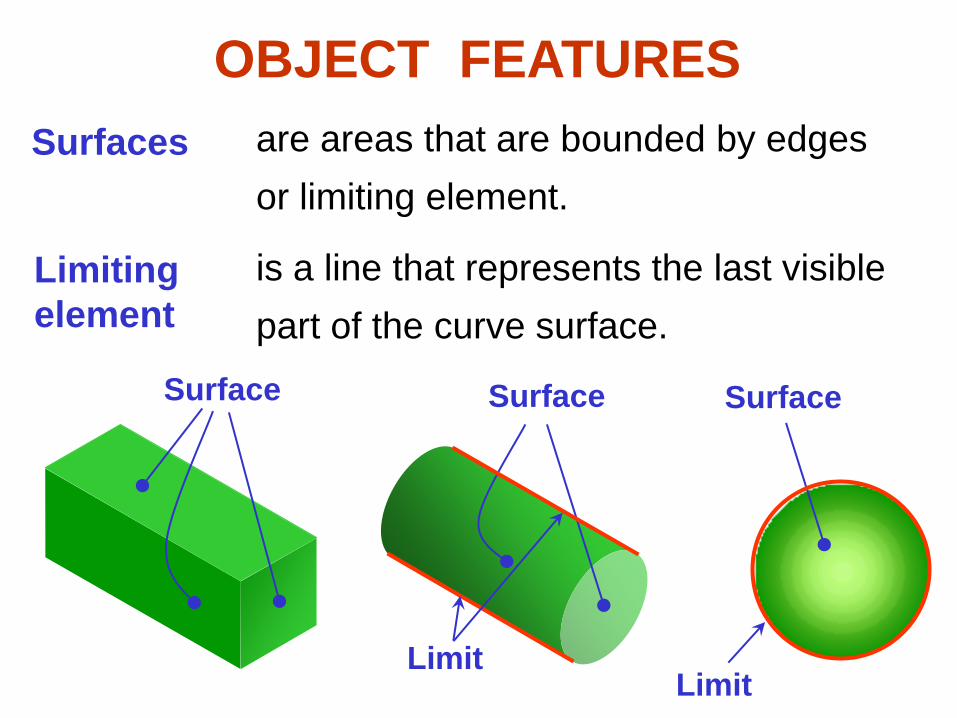
Surfaces are areas that are bounded by edges
or limiting element.
Limiting
element
is a line that represents the last visible
part of the curve surface.
Surface Surface Surface
LimitLimit
OBJECT FEATURES
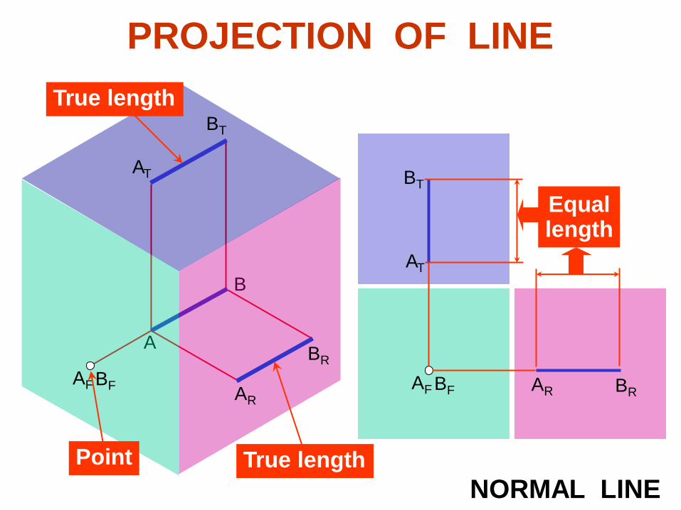
A
B
AF BF BRAR
AT
BT
BR
AR
AF BF
AT
BT
True length
NORMAL LINETrue lengthPoint
Equallength
PROJECTION OF LINE

AB
AF BF BRAR
AT
BT
INCLINED LINEForeshortened
BR
AR
AF
BF
Foreshortened
AT
BT
True length
A
Equallength
PROJECTION OF LINE

AB
AF
BF BR
AR
AT
BT
OBLIQUED LINE
A
Equallength
B
ForeshortenedForeshortened
Foreshortened
BR
AR
AF
BF
AT
BT
PROJECTION OF LINE

BC
A
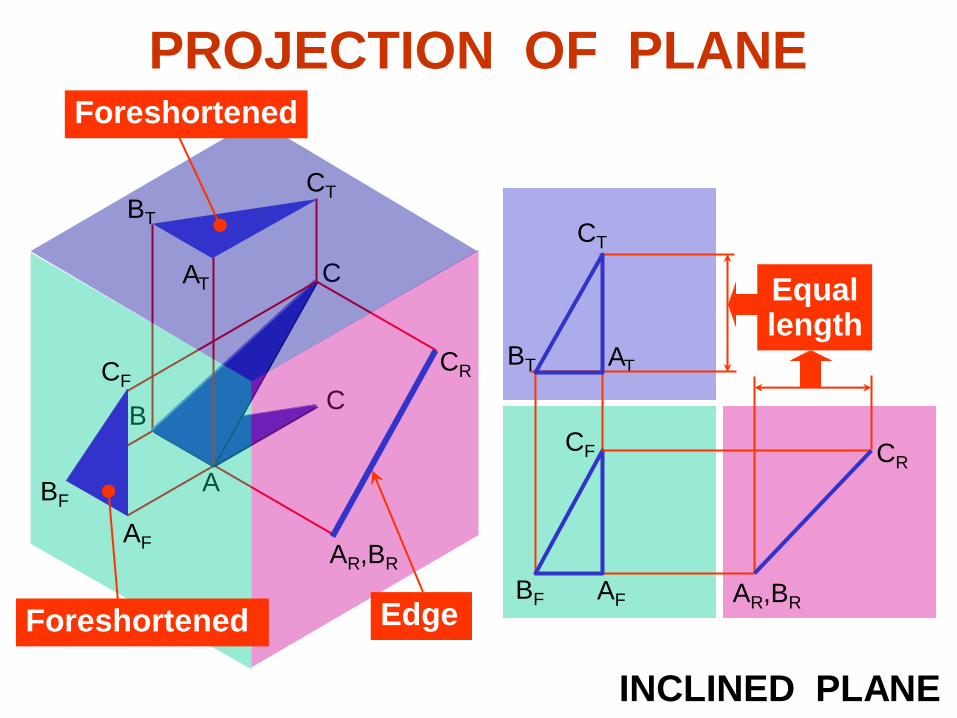
PROJECTION OF PLANE
BF AF,CF CRAR,BR
AT
CT
NORMAL PLANE
Equallength
EdgeEdge
True size
CR
AR,BR
AF,CF
BF
AT
BT
CT
BT
BC
BF AF
CR
AR,BR
AT
CT
INCLINED PLANE
A
Equallength
BT
C
CF
Edge
CR
AR,BR
Foreshortened
BT
CT
AT
AF
CF
Foreshortened
BF
PROJECTION OF PLANE

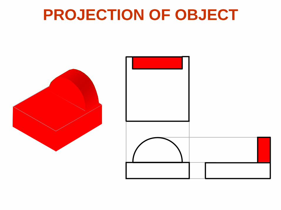
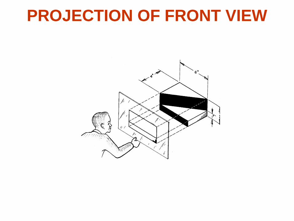
PROJECTION OF OBJECT
The views are obtained by projecting all object
features to the picture plane.
You have to project the remaining surfaces which areinvisible too !
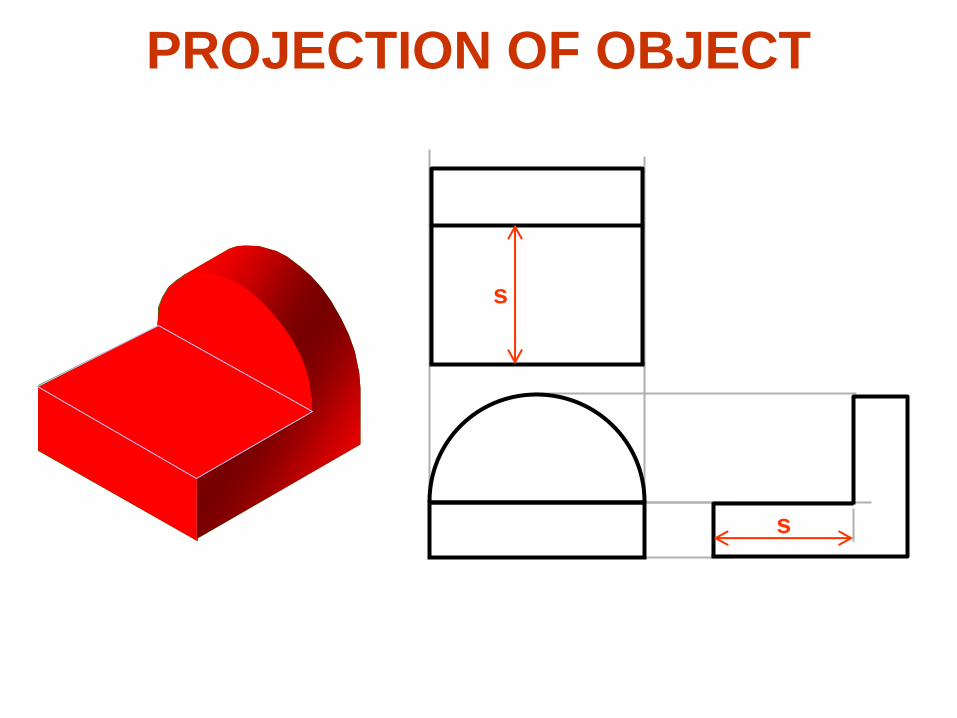
s
s
s
PROJECTION OF OBJECT
PROJECTION OF OBJECT

PROJECTION OF TOP VIEW

PROJECTION OF TOP VIEW
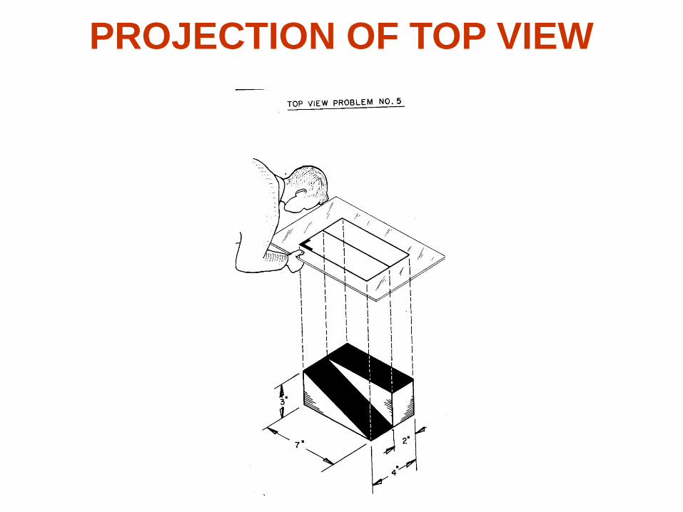
PROJECTION OF TOP VIEW

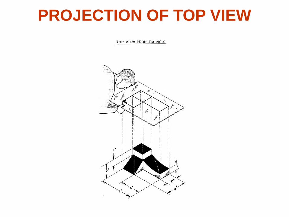
PROJECTION OF TOP VIEW

PROJECTION OF TOP VIEW

PROJECTION OF TOP VIEW
PROJECTION OF TOP VIEW

PROJECTION OF TOP VIEW
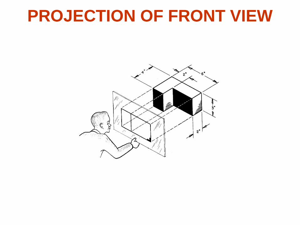
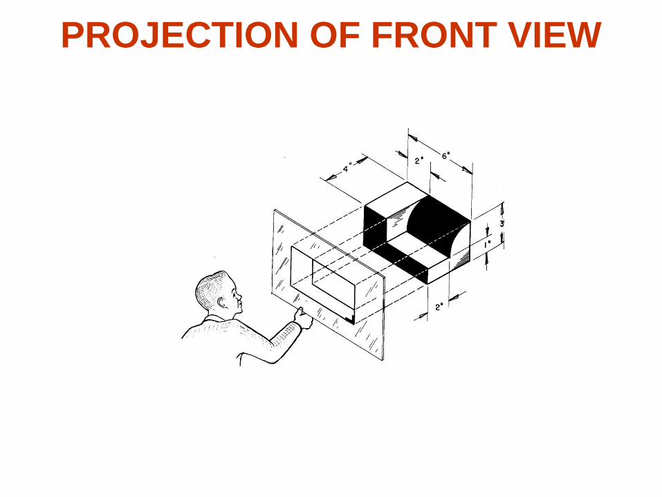
PROJECTION OF FRONT VIEW

PROJECTION OF FRONT VIEW
PROJECTION OF FRONT VIEW

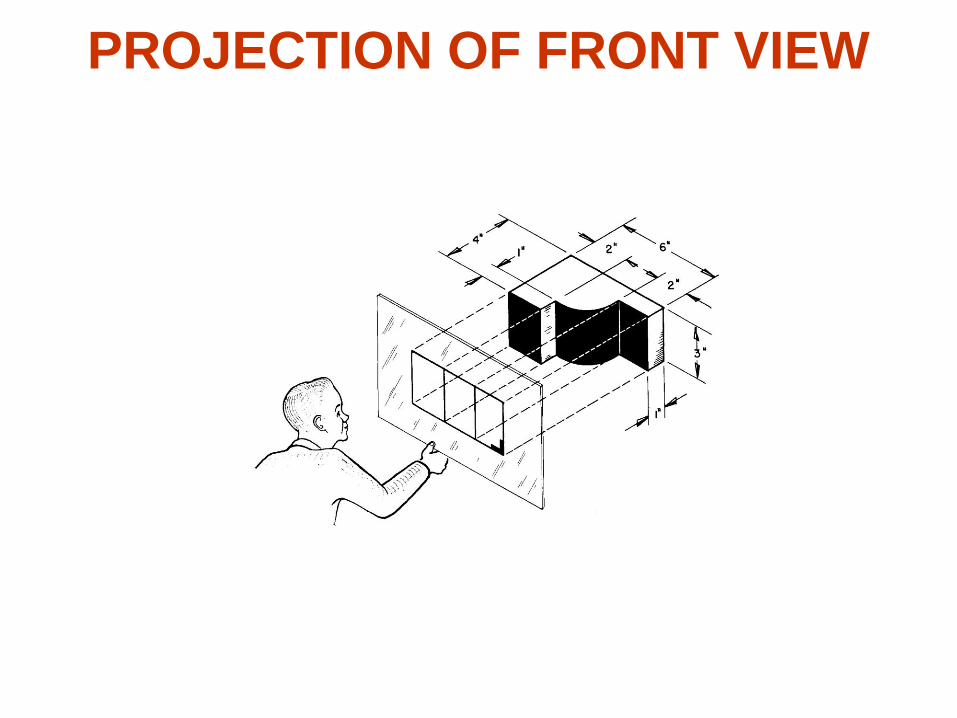
PROJECTION OF FRONT VIEW

PROJECTION OF FRONT VIEW
PROJECTION OF FRONT VIEW

PROJECTION OF FRONT VIEW
PROJECTION OF FRONT VIEW

PROJECTION OF FRONT VIEW

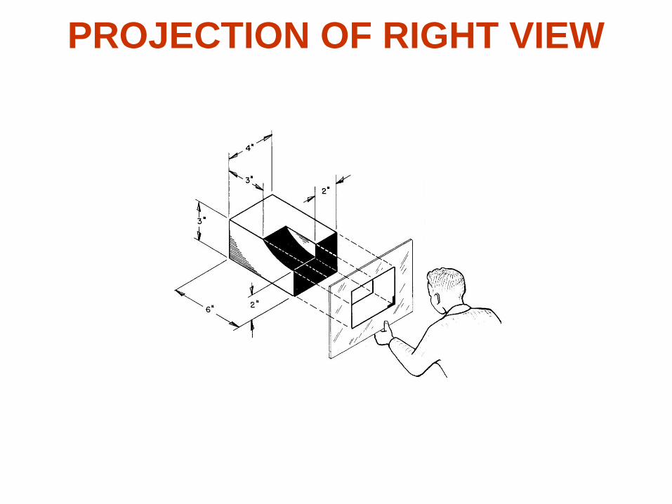
PROJECTION OF RIGHT VIEW

PROJECTION OF RIGHT VIEW

PROJECTION OF RIGHT VIEW

PROJECTION OF RIGHT VIEW
PROJECTION OF RIGHT VIEW

PROJECTION OF RIGHT VIEW

Line Convention The meaning of lines

LINE CONVENTION
Precedence of coincide lines
Hidden line drawing
Center line drawing
The meaning of lines

THE MEANING OF LINES
Object Lines
THE MEANING OF LINES
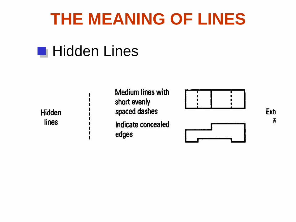
Hidden Lines
THE MEANING OF LINES
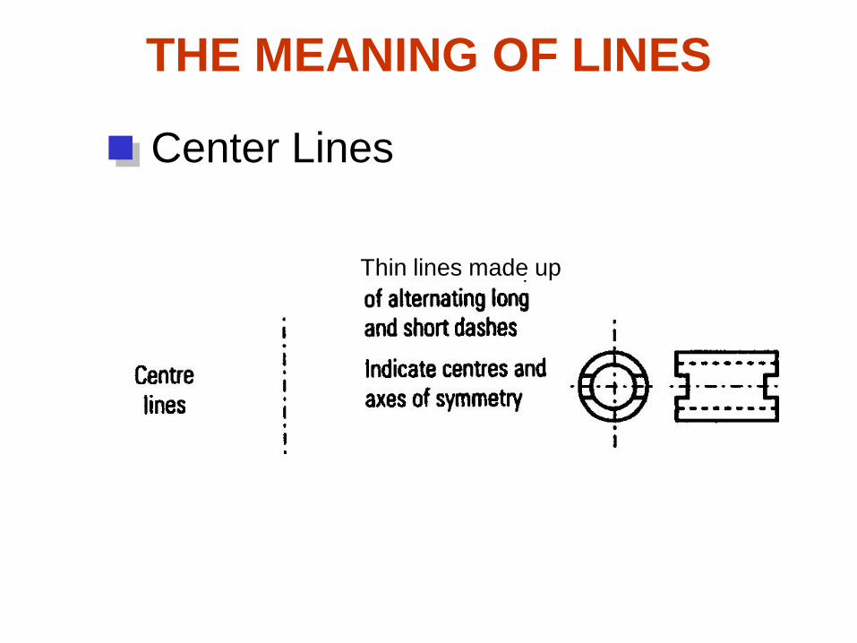
Center Lines
Thin lines made up

THE MEANING OF LINES
Dimension Lines

THE MEANING OF LINES
Extension Lines

PRECEDENCE OF LINE
Visible
line
Order of
importance
Hiddenline
Center
line
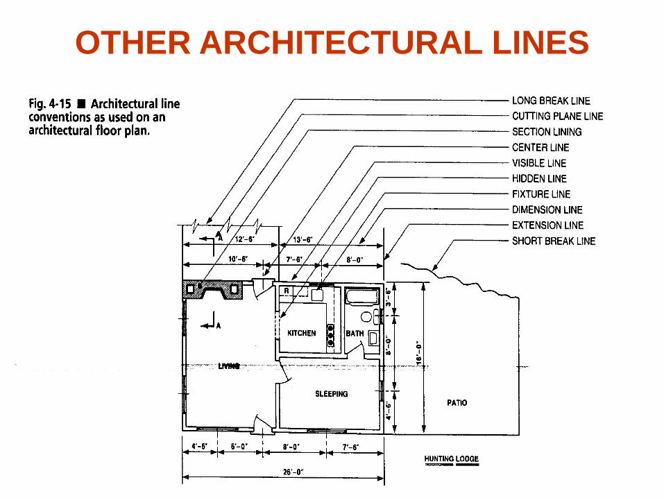
OTHER ARCHITECTURAL LINES
Hidden Lines

ARCHITECTURAL LINES
Other Lines
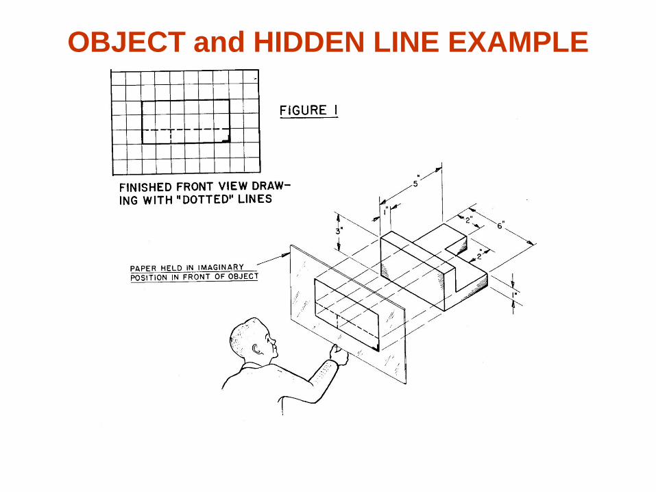
OBJECT and HIDDEN LINE EXAMPLE

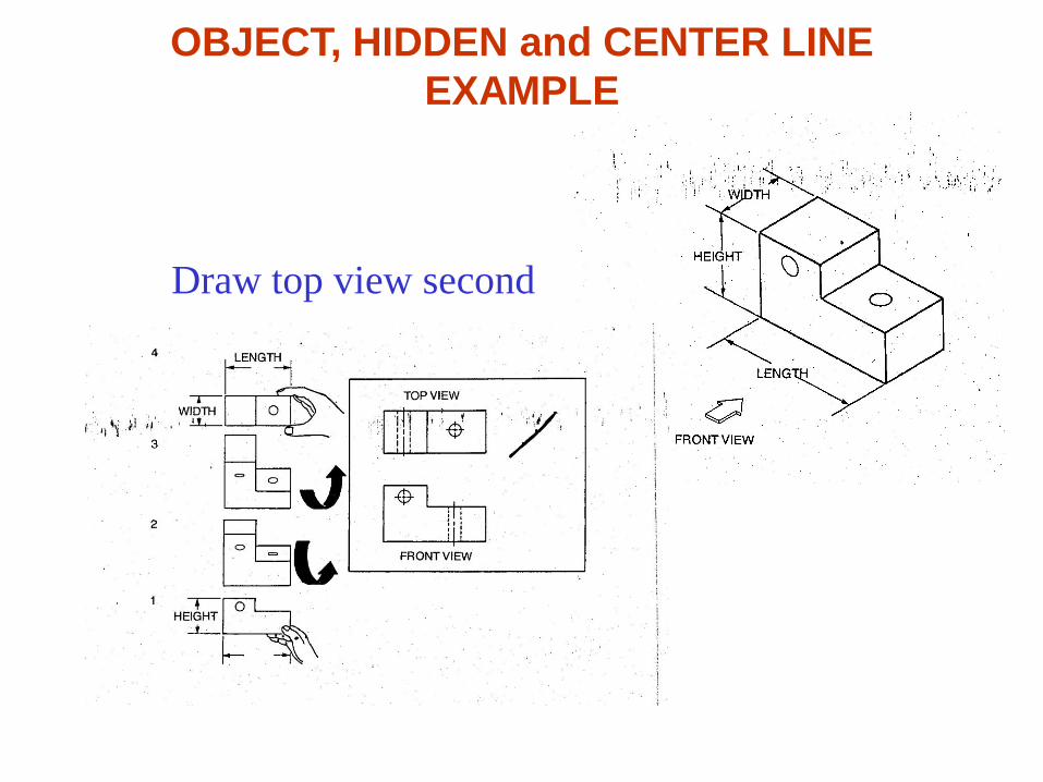
OBJECT, HIDDEN and CENTER LINE
EXAMPLE
Draw front view first
OBJECT, HIDDEN and CENTER LINE
EXAMPLE
Draw top view second
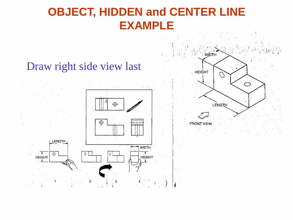
OBJECT, HIDDEN and CENTER LINE
EXAMPLE
Draw right side view last
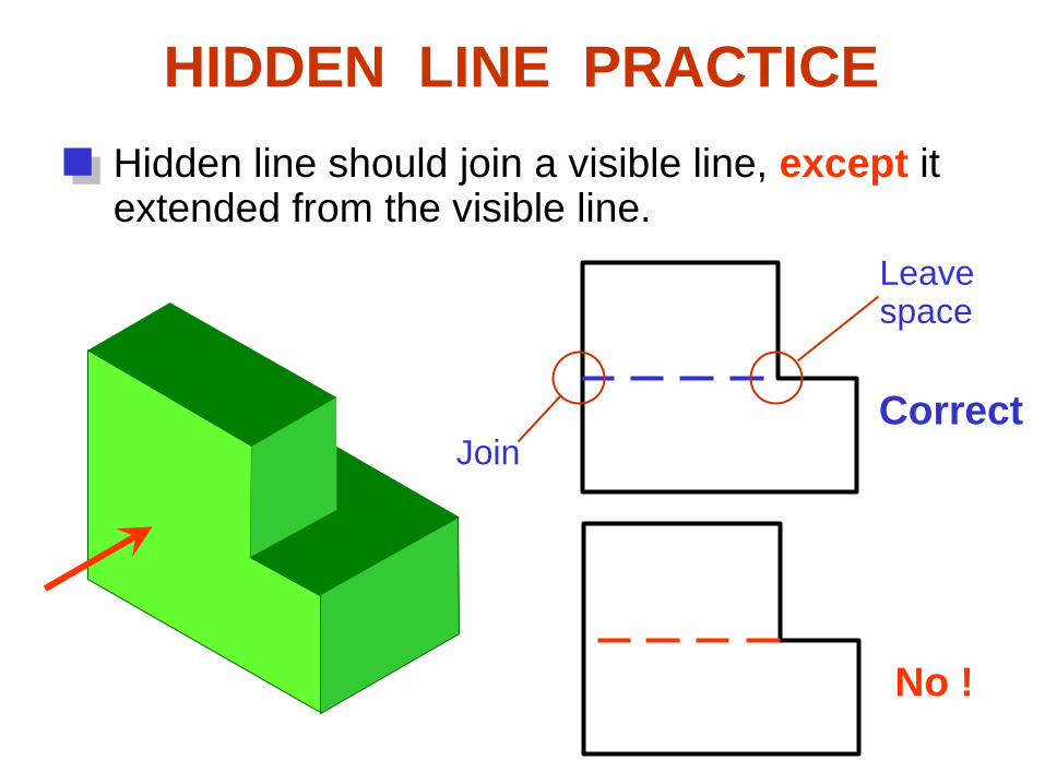
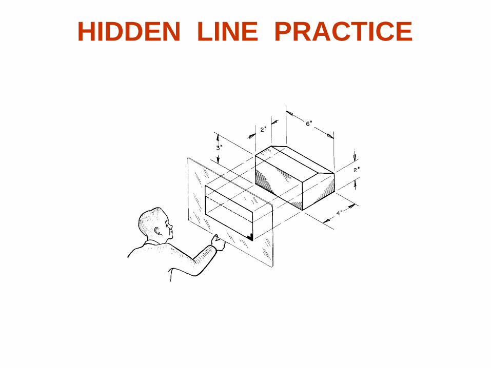
HIDDEN LINE PRACTICE
Hidden line should join a visible line, except itextended from the visible line.
Correct
No !
Join
Leavespace

Correct No !
Hidden line should join a visible line, except itextended from the visible line.
Leavespace
Leavespace
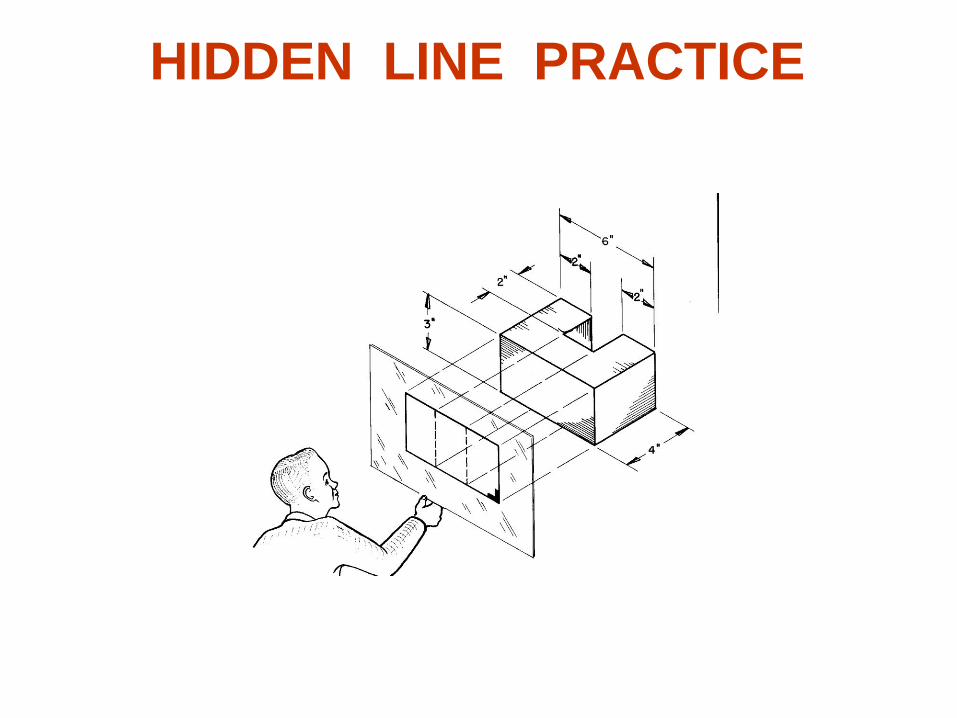
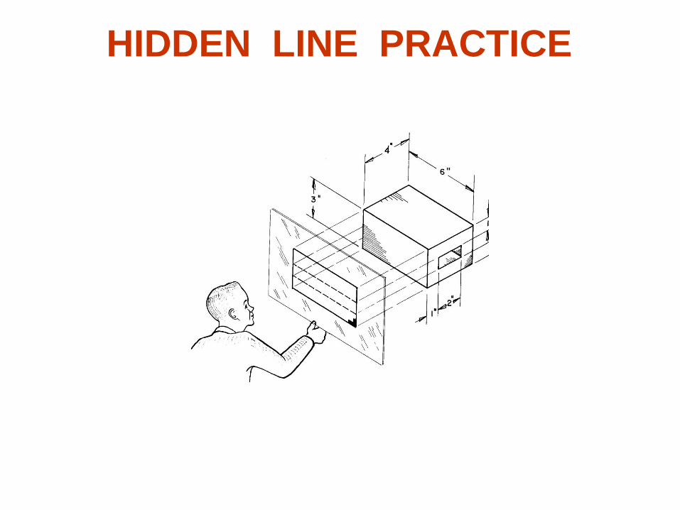
HIDDEN LINE PRACTICE

Hidden line should intersect to form L and Tcorners.
Correct
No !
L T
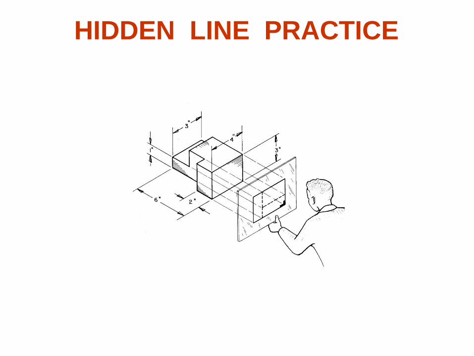
HIDDEN LINE PRACTICE

Hidden arcs should start on a center line.
HIDDEN LINE PRACTICE

HIDDEN LINE PRACTICE

HIDDEN LINE PRACTICE
HIDDEN LINE PRACTICE
HIDDEN LINE PRACTICE
HIDDEN LINE PRACTICE

HIDDEN LINE PRACTICE

HIDDEN LINE PRACTICE
HIDDEN LINE PRACTICE
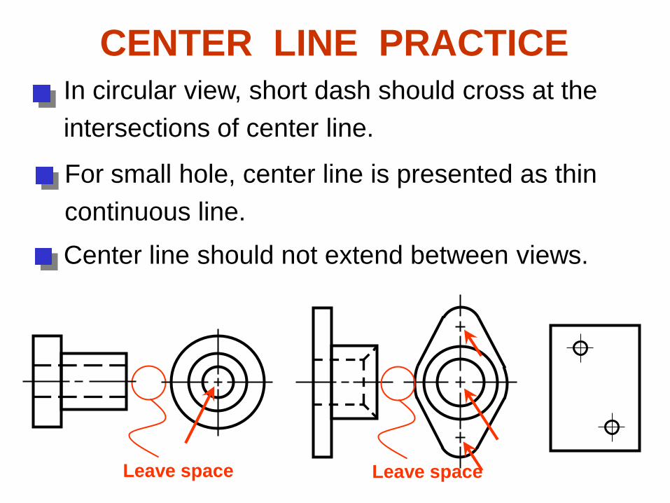
CENTER LINE PRACTICEIn circular view, short dash should cross at the
intersections of center line.
For small hole, center line is presented as thin
continuous line.
Center line should not extend between views.
Leave space Leave space

Leave the gap when centerline forms a
continuation with a visible or hidden line
Leavespace
Leavespace
Leavespace
Leavespace
Center line should always start and end with
long dash.
CENTER LINE PRACTICE

DRAWING USING A MITER
LINE

DRAWING USING A MITER
LINE

DRAWING USING A MITER
LINE
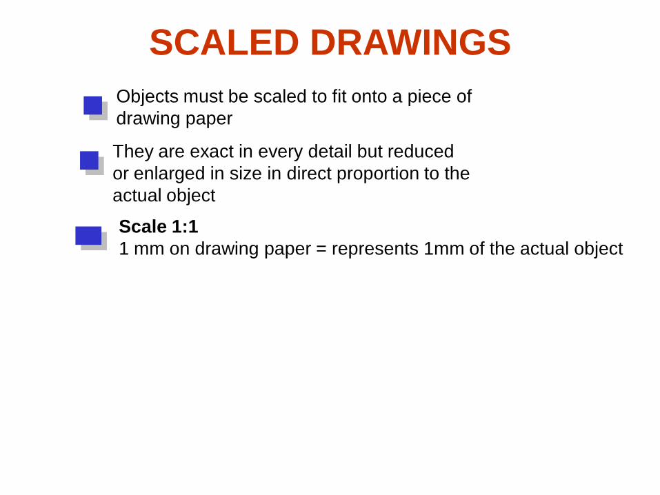
SCALED DRAWINGS
Objects must be scaled to fit onto a piece of
drawing paper
They are exact in every detail but reduced
or enlarged in size in direct proportion to the
actual object
Scale 1:1
1 mm on drawing paper = represents 1mm of the actual object
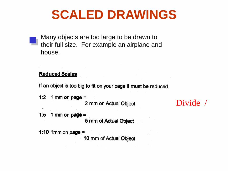
SCALED DRAWINGS
Divide /
Many objects are too large to be drawn to
their full size. For example an airplane and
house.

SCALED DRAWINGS
Details of small objects are clearer and
easier to dimension when they are drawn
larger then their actual size
Multiply X
Often it is necessary to produce drawings
larger than full size

TITLE BLOCK
A title block is a portion of a drawing that
is set aside to give important information
about the drawing. The drafter, the scale,
the units, and your name
You must “frame” your drawing to make it
look professional. Draw a 1 cm border
and a 1 cm high area for your title block
A title block template can be found on the
shared drive. Ask your teacher.

TITLE BLOCK TEMPLATE

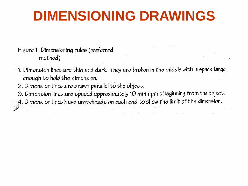
DIMENSIONING DRAWINGS
DIMENSIONING DRAWINGS
DIMENSIONING DRAWINGS
Ask your teacher for a
list of dimensioning
Rules
Dimensioning lines must
follow these rules
THE STAGE IS SET FOR YOU
TO BECOME AN EXPERT
TECHNICAL DRAWER
Practice drawing
worksheets can be
found on the shared
drive