ORNL-2796
40
EXPERIMENTAL MOL POWER REACTOR L. G. Alexander €3. W. Kinyon M. E. Lackey H. G. MacPherson J. Zasler J. W. Miller F: C. VonderLage G. D. Whitman
-
Upload
jon-morrow -
Category
Documents
-
view
215 -
download
0
description
http://www.energyfromthorium.com/pdf/ORNL-2796.pdf
Transcript of ORNL-2796
EXPERIMENTAL MOL POWER REACTOR
L. G. Alexander €3. W. Kinyon M. E. Lackey H. G. MacPherson J. Zas ler
J. W. Mi l ler F: C. VonderLage G. D. Whitman
Printed i n USA. Pr ice 025 . Availoble from the I I Off ice of Technical Services
Deportment of Commerce
Washington 25, D. C.
ILEGAL 1 This report was prepared as an account of Government sponsored work. Neither the United States.
nor the Commission, nor ony person octing on behalf of the Commission:
A. Makes any warranty or representotion. expressed or implied, w i th respect t o the occurocy,
completeness, or usefulness of the information contained i n this report, or that the use o f
ony informotion, apporotus, method, or process disclosed in this report may not infr inge
privately owned rights; or
B. Assumes any l iab i l i t ies wi th respect t o the use of, or for damages result ing from the use of any information, apparatus, method, or process disclosed i n this report.
As used i n the above, “person acting on behalf of the Commission” includes any employee or
controctor of the Commission, or employee of such contractor, to the extent thot such employee
or contractor of the Commission, or employee of such controctor prepares, disseminates, or
provides occess to, any information pursuant t o his employment or contract wi th the Commission,
or h i s employment wi th such controctar.
ORN L-2796
Contract No. W-7405-eng-26
REACTOR PROJECTS DIVISION
EXPERIMENTAL MOLTEN-SALT-FUELED 30-MW POWER REACTOR
L. G. Alexander B. W. Kinyon M. E. Lackey H. G. MacPherson J. Zasler
J. W. Miller F. C. VonderLage G. D. Whitman
DATE ISSUED
OAK RIDGE NATIONAL LABORATORY Oak Ridge, T e n n e s s e e
operated by UNION CARBIDE CORPORATION
for t h e U. 5. ATOMIC ENERGY COMMISSION


CONTENTS
Abstract ................................................................................................................................................................ 1
Introduction and Conclusions ............................................................................................................................ 1
General Description of Reactor and Plant Layout .......................................................................................... 1
Molten-Salt System Auxiliaries .......................................................................................................................... 10
Enriching and Sampling System ...................................................................................................................... 10 Fi I I and Drain System ...................................................................................................................................... 13 Preheating and Afterheat Removal Equipment ............................................................................................ 14 Off-Gas System ................................................................................................................................................ 16
16 Molten-Sa It Pumps and Heat Transfer Equipment .......................................................................................... Steam Generating Equipment and Turbine-E lectric System .......................................................................... 20
Remote f~~aintenance ............................................................................................................................................ 20
Nuclear Performance .......................................................................................................................................... 21
Reactor Hazards .................................................................................................................................................. 23
Costs .................................................................................................................................................................... 26
Alternate Designs ................................................................................................................................................ 28
L i s t of Drawings .................................................................................................................................................. 32
iii
.

V
3
1
EXPERIMENTAL MOLTEN-SALT-FUELED 30-MW POWER REACTOR
L. G. Alexander M. E. Lackey J. W. Miller G. D. Whiitman B. W. Kinyon H. G. MacPherson f. C. VonderLage J. Zasler
A B S T R A C T
A preliminary design study has been made of an experimental molten-salt-fueled power
The reactor considered i s a single-region homogeneous burner coupled wi th a Loeff ler
Conceptual plant layouts, basic information on the major fuel circuit
The design plant electrical output is 10,000 kw, and the total construction cost i s estimated
reactor,
steam-generating cycle,
components, a process flowsheet, and the nuclear characteristics of the core are presented.
t o be approximately $16,000,000.
I N TRO D U C T ION AND CONCLUSIONS
The molten-salt-fueled reactor system described in this report represents a preliminary design and is to be considered as a reference design for further experimental molten-salt-fueled reactor studies. Designs have been developed for the major components which are sufficiently detailed to permit an init ial evaluation of costs and con- struction problems. Information on nuclear per- formance was obtained to give a basis for study of the major problems involved in operating a molten-salt-fueled power reactor.
The molten-salt concept has been considered for a variety of reactor types. These may be classified as homogeneous or graphitemoderated systems, in the main, wi th a variety of modifi- cations depending on parti cu I or obi ectives. Single- and two-region homogeneous reactors have been considered in burnel pnd converter cycles, and, most recen d-graph i te-moderated reactors have b sized for breeding cycles. The major aim of th is study was to design a nuclear power plant which, wi th a minimum of
ntal effort, could be built in the near nsi derabl e information
ore complex molten-salt s’objective in mind, a s burner employing a
irect-mai ntenance concept, operating on nd producing 10 Mw of
stem embodies a simple core from which h a coolant salt to a
steam system to produce a useful amount of power
reference design.
>
by a proved cycle. The semidirect-maintenance philosophy circumvents the more compl icated oper- at ions i nvo I ved in comp I ete remote-mai n ten ance schemes, but does not prevent the replacement of the more vulnerable components of the fluid-fuel system.
This reactor plant could be used tcl demonstrate the nuclear performance of a homogeneous core, the reliability of components, the stability of the molten-salt fuels, the handling of gross quantities of molten salts, the chemical processing of fissioned fuel, the containment and processing of fission gases which would be stripped from the fluid fuel, the application of a particular high- pressure, high-temperature steam cycle to the molten-salt system, and the practicality of certain maintenance techniques. In addition to the pr imar i ly technical data, cost information would be obtained on the construction and operation of a molten-salt-fueled power reactor. It has been estimated that this experimental reactor would cost approximately $16,000,000 and that about two and one-half years would be required for construction. The general characteristics of the system are listed in Table 1.
G E N E R A L D E S C R I P T I O N OF R E A C T O R A N D P L A N T L A Y O U T
The molten-salt-fueled reactor system adopted for this study incorporates a complete electric generating station but does not include on-site fuel reprocessing foci l i t ies or a major-equipment remote-maintenance repair shop. The successful operation of an experimental reactor would not
1

Table 1. Reactor Plant Characterist ics 7
1 >90% U235F4 F uel
Fuel carrier 63 mole % LiF, 37 mole % BeF2
Intermediate Neutron energy
Moderator Li F-BeF2
Primary coolant
Power
Fuel solut ion circulat ing at 1480 gpm
10 Mw
30 Mw
Electr ic
Heat
Estimated cost
Refueling cycle
Shielding
Control
erature
Temperature
Pressure
' Intermediate coolant
$16,000,000
Semicontinuous
Concrete
Temperature and fuel concentration
1235" F
1000° F
1450 psi0
65 mole % LiF, 35 mole % BeF2
Str uct ural material s I
INOR-8
Coolant system INOR-8
Steam superheater INOR-8 I
6 f t Core dia'meter
erature coeff icient of reactivi ty, (Sk/k)/OF -6.75
417 kw/kg
9.4 kw/ l i ter Power density (core)
Fuel inventory
In i t ia l (clean)
After second year
Cr i t ica l mass (clean)
65.8 kg of U235
107 k g of U235
end on continuous fuel reprocessing, and, drain sy ong-term exposure of the fuel carrier
required to achieve fission product tions comparable to those expected in molten-salt-fueled power systems. Smal I
of fuel could be withdrawn from the
which could then be transported to the ORNL facilities for experiments in chemical reproc- essing.
One of the primary objectives of the reactor experiment would be to determine the metallurgical
1
a
2

and structural reliability of components. Maior remote repair facilities were not included in the design, but on-site decontamination and de- structive disassembly foci l i t ies were provided so that manageable specimens of the fuel components could be obtained and transported to ORNL hot shops for inspection. It i s intended that part of the hot storage cell be used for such work.
single-unit primary container by a centrifugal pump, and a single coolant-salt system containing LiF-BeF, i s used as the heat transfer coupling between the fuel and the steam superheater. A salt coolant has several advantages over a liquid metal coolant in th is ' application, such as com- patibility wi th the fuel salt, lower fnduced radio activity coupled with a much faster decay rate, nonflammabi lity, and elimination of cold-trap cir- cuits. The major disadvantage of the coolant salt i s o relatively high liquidus temperature (865OF) which increases the preheating load and increases the danger of freezeup at off-design conditions.
A Loeffler steam cycle i s used because of i ts unique adaptability to the molten-salt-fueled re-
relative merits of this system have ed in connection w i th earlier molten-
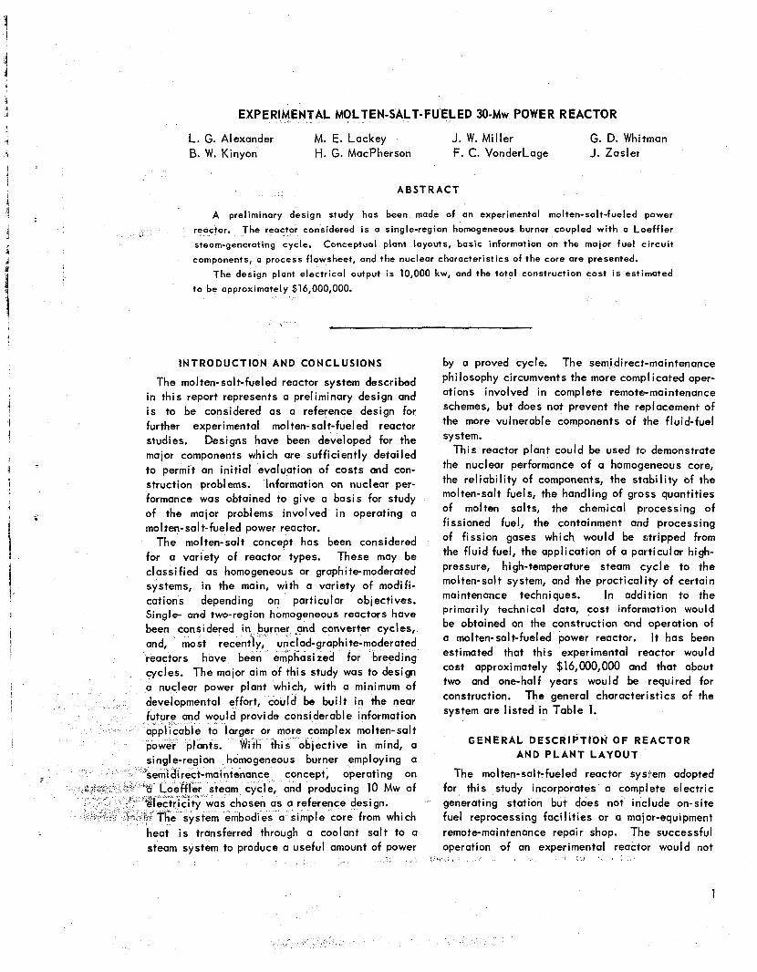
salt-fueled reactor studies. The primary fuel container i s made up of a
single structure which forms the core, heat ex- changer, expansion tank, and fuel pump volute. This assembly, along wi th the gas heating and cooling jacket, i s shown in Fig. 1. The primary fuel container weldment i s shown in Fig. 2.
The fuel i s recirculated through the system by means of a sump-type centrifugal pump. The fluid
er heat exchanger header from the through the tubes.
at exchanger, the fluid
The fuel, LiF-BeF,-UF,, i s
1
2
in+- +e pump by means of annulus The flob ullrclru lIIIv
* I ,,I I . I
'D. J. McGoff et aI., olten-Salt Reactor, E IT Proctice School, UC 2H. G . MacPherson et al., Molten-Salt Reactor Program
Status Repor t , ORNL-2634 (Nov. 12, 1958).
pump inlet. The entire upper region container assembly serves as a fue tank.
of the fuel expan sion
Some flow i s directed up out of the heat ex- changer inlet header for fission-gas removal and i s recirculated in the expansion tank through the pump. The fission gases are purged from the fuel and held temporarily in tanks located in the reactor cell. A dip line i s inserted to the bottom of the core for fuel f i l l ing and draining.
The heat exchanger and pump are removed or inserted from above. These major components can be changed without breaking l iquid seals, since their closures are made in a gas volume above the fuel level.
The fuel container i s surrounded by a jacket of stainless steel, which serves as a container for forced-circulation gas preheating crnd cooling. The cooling unit was added so that afterheat could be removed, in an emergency, without draining the system. The package comprising the gos blower, heater, and cooler i s arranged to be removed vertically from above, as in the case of the heat exchanger and fuel pump.
The entire assembly i s housed in a two-layer, gas-buffered steel enclosure, which i s surrounded on the sides by 8 ft of concrete shielding. The heat exchanger and pump project upward through 5 f t of concrete so that semidirect maintenance operations may be performed in a shielded area. A multilayer organic-cooled boron steel shield surrounds the reactor to reduce the radiation level in the reactor cell.
The coolant salt, which forms the intermediate coupling between the fuel and steam systems, is directed into the heat exchanger through a central pipe. This fluid flows on the outside of the tubes and out of the heat exchanger through the annular pipe.
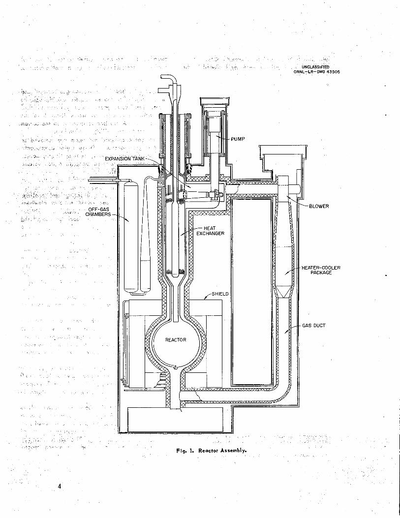
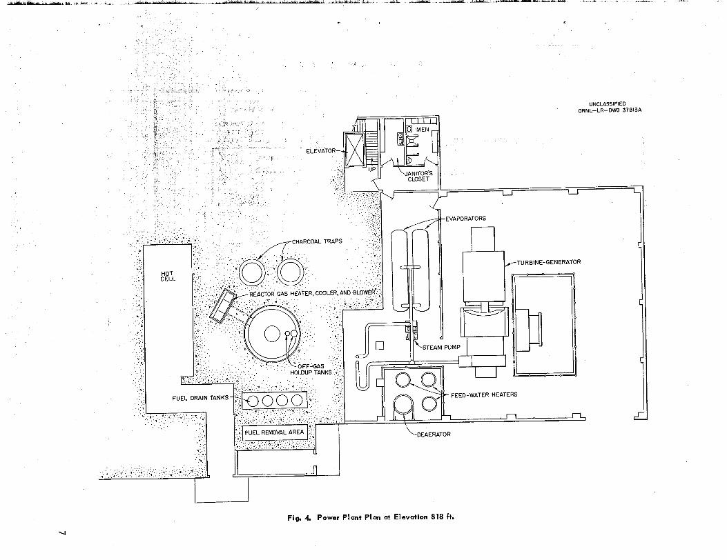
An elevation drawing of the plant i s shown in Fig- 3, and two plan views at elevations 818.0
846 ft are shown in Figs. 4 and 5, respec- tively. A perspective view of the! building i s shown in Fig. 6.
ely above the reactor cel l i s t el system maintenance oper- ations. Contaminated parts may be iremoved from this maintenance bay to a hot storage cell, which i s included in the building. The maiintenance bay i s shielded and i s sealed off during reactor oeerat ion.
3
b
EXPF i r
OFF-GAS CHAMBERS-
ORNL-LR-DWG 43505
h
PUMP
-BLOWER
H EATER-COO LE R PACKAGE
GAS DUCT
-.< Fiq. 1. Reactor Assembly.
4

UNCLASSIFIED ORNL-LR-DWG 39229A
~
TOP VIEW THROUGH EXPANSION TANK
VGAS SEAL WELD JUNCTURE
\PUMP DISCHARGE
7 HEAT EXCHANGER HOUSING
-FUEL RETURN ANNULUS
Fig. 2. Fuel Container Weldment and Gos Jacket.
ISOMETRIC OF
5

.>
i
W
.. ...- ;;
, _. ..
.
a
- I a w
Li 0
ta
u) a z 3
a
W
v)
z
W
z
n
8 n
a z
6
U
U
U
a
2 a W z
W 0
b
L m
a
3
0)
tK 0
5-
a
B 4
7
8
1 I a
c
a
a
5 [L
W
Y 2
F [
5 (I 0 C - c
:
U
> u m i
w
W
c
- I
I II
I '"! O
-il88
I

32
? i(
... +
E
0
P
- P
9
The intermedi ate-cool ant superheater are housed in area which i s accessible
pump and the steam a separate shielded
from above. Direct maintenance i s planned for this portion of the system. As previously mentioned, the induced radioactivity i n the coolant salt would decay rapidly, and direct maintenance could be performed after a few minutes' delay to allow the 11-sec fluorine activity to decay.
The Loeffler system evaporators and steam pump are located in the turbine-generator bay. The bridge crane, in the turbine-generator bay, i s located to service the Loeffler components, feed- water heaters, deaerator, and turbine-generator system.
The control room i s located between the reactor area and the turbine bay. Office and laboratory space i s located to one side of the plant and extends over four floors. An extended work area surrounds the reactor cel l on three sides at the 834.5-ft elevation.
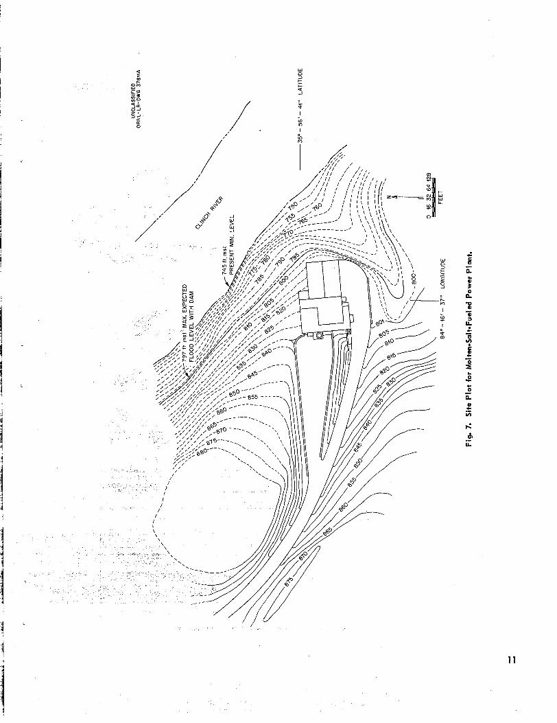
A site was chosen along the Clinch River at Gallaher Bend in the Oak Ridge area. The site plot i s shown in Fig. 7. The plant i s located on sloping terrain, which would minimize the ex- cavation requirements, since the general arrange- ment placed the reactor cell well above the condenser to prevent the possibility of flooding. This layout minimizes cooling water pumping requirements, but increases the building costs. This relationship has been optimized, and the arrangement prese was selected as a reosonable f irst approximation.
MOL T E N - S A L T SYSTEM A U X I L I A R 1 ES
Enriching and Sampling System
Fissionable material i s to be added to the circulating fuel on a semicontinuous basis to sustain criticality, within design temperature limits, and fuel samples are to be withdrawn throughout the course of operation for chemical assay. A relatively small volume of fissionable material wi l l be added at any one time, and a comparable, or smaller, volume wi l l be withdrawn as a sample.
A single mechanism i s provided to accomplish both these operations. The fuel wi l l be added as solid U235F, at a free liquid surface in the fuel system expansion tank or in a separate vessel in which a free surface wi I I be accompli shed by
10
i s presented. Sampling reversing this operation.
That is, a small portion of the circulating fuel wi l l be removed by "thief sampling," allowed to solidify, and then placed in a shielded container for transfer out of the area.
It i s estimated that 70 kg of U235 would have to be added to the system during the f irst two years of power operation (30 Mw at 100% plant factor) to take care of burnup and fission product over- ride. This quantit i s equivalent to a daily addition of 96 g of UJ3'. Considering the density of UF, to be 6.70 g/cm3, it may be seen that approximately 14.3 cm3 of UF, would have to be added daily.
The frequency of additions would be contingent on the al lowable mean temperature deviation i n the fuel system. The quantity of fissionable material, AM, consumed per day was calculated, as mentioned above, to be 96 g. Without fuel additions, this would result in some mean temper- ature decrease of the fuel, AT,. These quantities can be related as follows:
AM
a BM ATm =- ,
where a i s the temperature coefficient of reactivity per O F , B i s the mass reactivity coefficient, and M i s the critical inventory in grams. For a temper- ature coefficient of -6.75 x an assumed mass reactivity coefficient of 9, and a crit ical inventory of 90 kg, a mean temperature drop of less than 2OF per day would be experienced. The system could be operated at ful l power for several days before the decrease in fuel temperature would seriously affect the thermodynamics of the power cycle.
Several experiments have been run in which slugs of UF, weighing approximately 40 g have been inserted into 1200°F LiF-BeF2 salt to study solution rates and homogeneity of the UF, i n the melt.3 The UF, slugs were held in per- forated copper tubes, and the tubes were dipped into the salt mixture. The results of these tests indicate that solid UF, dissolves quite rapidly. The chemical assays of the resultant mixture gave excel lent material bo1 ances.
The fuel sampling and enriching device i s shown schematically i n Fig. 8. The entire
3MSR Quat. Prog. Rep . Apt . 30, 1959, ORNL-2723, p 92.
c
d / I ,/ 1 i! I
c E
1 1

Fig. 8. Fuel Sampling and Enriching Mechanism.
12
mechanism i s enclosed in a vacuum-tight struc- ture. A l l the material transfers in and out of the reactor system are made at “air lock” sections which can be purged and isolated from the process and cell side of the equipment. This equipment would be maintained by the semidirect type of techniques employed on the other major com- ponents of the fuel system.
The mechanism consists of a sample Carrier elevator, enricher elevator, horizontal conveyer, and reactor sample enricher elevator. The ele- vator sections transport the capsules between their respective containers and the horizontal conveyer section which interconnects the three vertical sections. Actuation of these elevator elements i s accomplished by motor-driven gear packages.
Isolation of the various sections of the mecha- nism i s accomplished by remotely operated ball and gate gas valves. Gas connections made between pairs of valves allow contaminated gas to be purged from the connections before dis- assembly and inert gas to be charged into the system after a connection has been made. A l l operation must be remotely controlled and w i l l be interlocked to prevent improper manipulation of the equipment. Preliminary layout drawings have been made of this mechanism, and details for the gas valve operators and capsule handling have been developed.
storage i ty of approximately 400 ft3 i s provided.
This svstem i s made UD of four vertical cvlinders
each pair of valves. Fluid i s transferred from the drain vessels to the reactor or vice versa by applying differential gas pressure to establish flow. During this operation the mechanical valves are open and the gas vent to the surge chamber i s closed. When this gas vent i s opened and pressures in the reactor and drain gas systems are equalized, flow i s stopped and further f lu id transfer i s impossible. The mechanical valves may then be closed. They would not normally be exposed to liquid. The surge charnber also provides a source of buffer gas between the mechanical valves when the fluid i s in the drain system and the reactor vessel must be opened for maintenance.
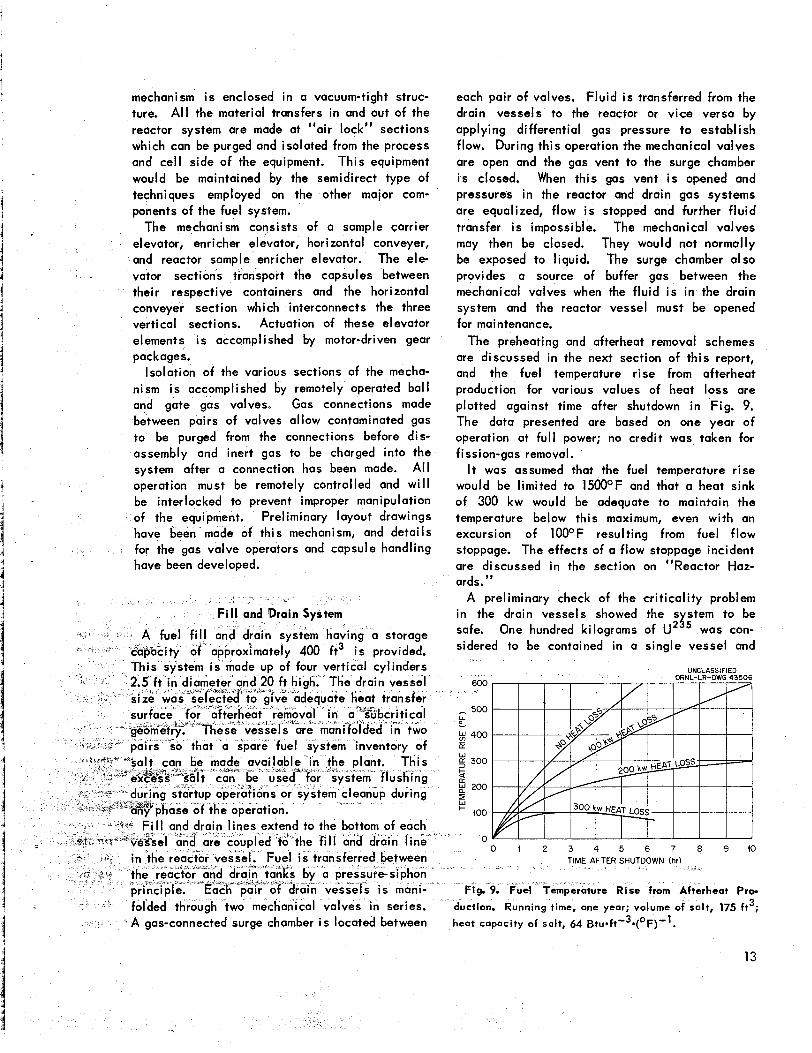
The preheating and afterheat removal schemes are discussed in the next section of this report, and the fuel temperature rise from afterheat production for various values of heat loss are plotted against time after shutdown in) Fig. 9. The data presented are based on one year of operation at fu l l power; no credit was taken for f i ssi on-gas removal.
It was assumed that the fuel tempertrture rise would be limited to 1500OF and that a heat sink of 300 kw would be adequate to maintain the temperature below this maximum, even wi th an excursion of 100°F resulting from ifuel flow stoppage. The effects of a flow stoppage! incident are discussed in the section on “Reactor Haz- ards.”
A preliminary check of the crit icality problem in the drain vessels showed the s stem to be safe. One hundred kilograms of UzYs was con- sidered to be contained in a single vessel and
UNCLASSIFIED ORNL-LR-DWG 43506 600
- 500 P % 400 E
300
....
G g 200 a LL
100
0
+
Fig. 9. Fuel T ture Rise from Afttrrheat Pro-
duction. Running time, one year; volume of salt, 175 ft3; heat capacity of salt, 64 B t ~ * f t - ~ * ( ~ F ) ” . ge chamber i s located between
13
i esumed to be settling out of the carrier
oxide compound, so that a l l the Id be contained in the d the top surface would
be refiected by the carrier salt. ' When the U235 was contained in the lower half of the vessel, a 10-ft-high by 2.5-ft-dia volume, the multiplication constant was 0.596. When the U235 was con- sidered to be contained in the bottom as a cube 2.5 ft on a side, the multiplication constant in- creased to 0.827. This value was considered uncomfortably high; however, the drai n-vessel diameter could be reduced at the bottom to offset
rier and spent fuel salt would be loaded ut of the plant via the drain vessels at sfer area adjacent to the drain vessels. iquid connections, probably flanges,
e provided in the lines used to transfer radioactive moterial out of the plant. It was presumed that freeze-flange junctions could be used in this opplication. These transfers would be made infrequently, and the transfer equipment would not be used for long periods.
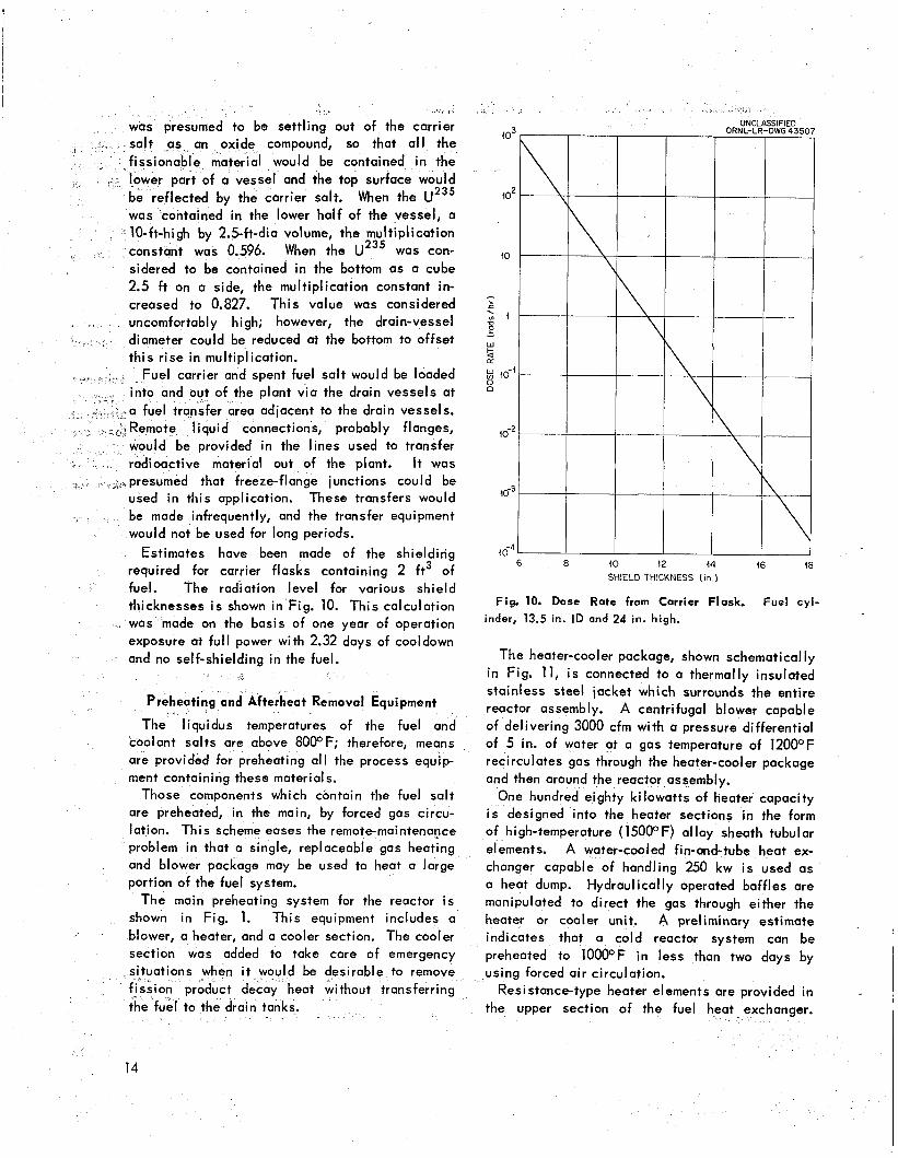
required for carrier flasks containing 2 ft3 of fuel. The radiation level for various shield thicknesses is shown in ~ i ~ . 10. This was made on the basis of one year of operation
Estimates have been made of the shielding 46"' I 6 8 40 12 44 16 18
SHIELD THICKNESS On.)
Fig. 10. Dose Rate from Carrier Flask. Fuel cy!- indert 13s5 in. I D and 24 in . high*
exposure at full power with 2.32 days of cooldown and no self-shielding in the fuel.
tins and Afterheat Removal Equipment
quidus temperatures of the fuel and coolant salts are above 8000F; therefore, means are provided for preheating all the process equip- ment containing these materials.
Those components which contain the fuel salt are preheated, in the main, by forced gas circu- lation. This scheme eases the remotemaintenocce problem in that a single, replaceable gas heating and blower package may be used to heat a large portion of the fuel system.
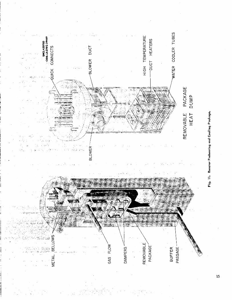
The main preheating system for the reactor i s shown in Fig. 1. This equipment includes a blower, a heater, ond a cooler section. The cooler section was added to take care of emergency
sirable to remove fission product d eat without transferring {he fuel to the drain tanks.
14
The heater-cooler package, shown schematically in Fig. 11, i s connected to a thermally insulated stainless steel jacket which surrounds the entire reactor assembly. A centrifugal blower capable of delivering 3000 cfm with a pressure differential of 5 in. of water at a gas temperature of 12OOOF recirculates gas through the heater-cooler package and then around the reactor assembly.
One hundred eighty kilowatts of heater capacity i s designed into the heater sections in the form of high-temperature (150OOF) alloy sheath tubular elements. A water-cooled fin-and-tube heat ex- changer capable of handling 250 kw i s used as a heat dump. Hydraulically operated baffles are manipulated to direct the gas through either the heater or cooler unit. A preliminary estimate indicates that a cold reactor system can be preheoted to 1OOOOF in less than two days by using forced air circulation.
Resistance-type heater elements are provided in the upper section of the fuel heat exchanger.
6 VI
Y
O
m
0
n
.- - s -0
O
m .- + u & t n $ c U
u K
15

Similar preheating units are included i n the fuel pump region and i n the removable portion of the pump. These heaters may be replaced from above the top shield.
The fuel drain lines and drain vessels are preheated by circulating gas systems. The drain vessels have heater-cooler packages simi lor to the reactor package.
The coolant-salt system i s preheated with re- sistance heaters attached to the lines and in- dividual components. These elements wi l l be maintained directly, and no particular service problem i s envisioned.
C Y
Off-Gas System
As previously mentioned, a portion (approxi- mately 10%) of the fuel flow i s bypassed through a gas stripping system. Directly above the fuel heat exchanger inlet header there are nozzles located in a plate to jet the fuel into the gas space. **
Helium i s admitted into the expansion tank from a fuel pump purge at a rate of 1 scfh. This gas and the gaseous fission products stripped from the recirculating fuel are taken out of the fuel surge tank to primary holdup tanks, which are located i n the main reactor cell. The effluent from these tanks is then circulated out of the system into two stages of cooled charcoal beds which hold up the krypton and xenon. The purge gas, then essentially free from activity, i s purged back into the reactor expansion tank. Parallel installations of charcoal beds and gas recircu- lating pump are installed in the system to ensure continuous operation.
M O L T E N - S A L T P U M P S A N D H E A T T R A N S F E R E Q U I P M E N T
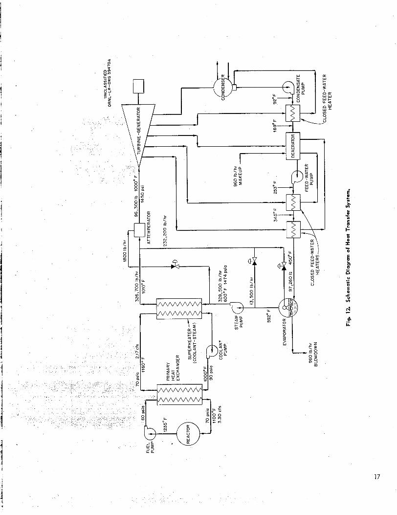
agram for the experimental reactor ig. 12. Fuel i s circulated in the
by means of a sump-type cen- trifugal pump. This pump has a salt-lubricated lower bearing which i s submerged in the fuel. The upper bearing assembly i s oil-lubricated and includes a radial bearing, a thrust bearing, and a face seal. The electric motor rotor is on the shaft above the upper bearing. The rotor i s canned, so that the field windings may be replaced without breaking a reactor seal. A shield section i s installed between the fuel surface and the upper bearing assembly. Cooling must be provided for
the shield and shaft. The entire rotating pump assembly may be removed as a unit, while the volute section i s a part of the fuel surge tank and reactor assembly.
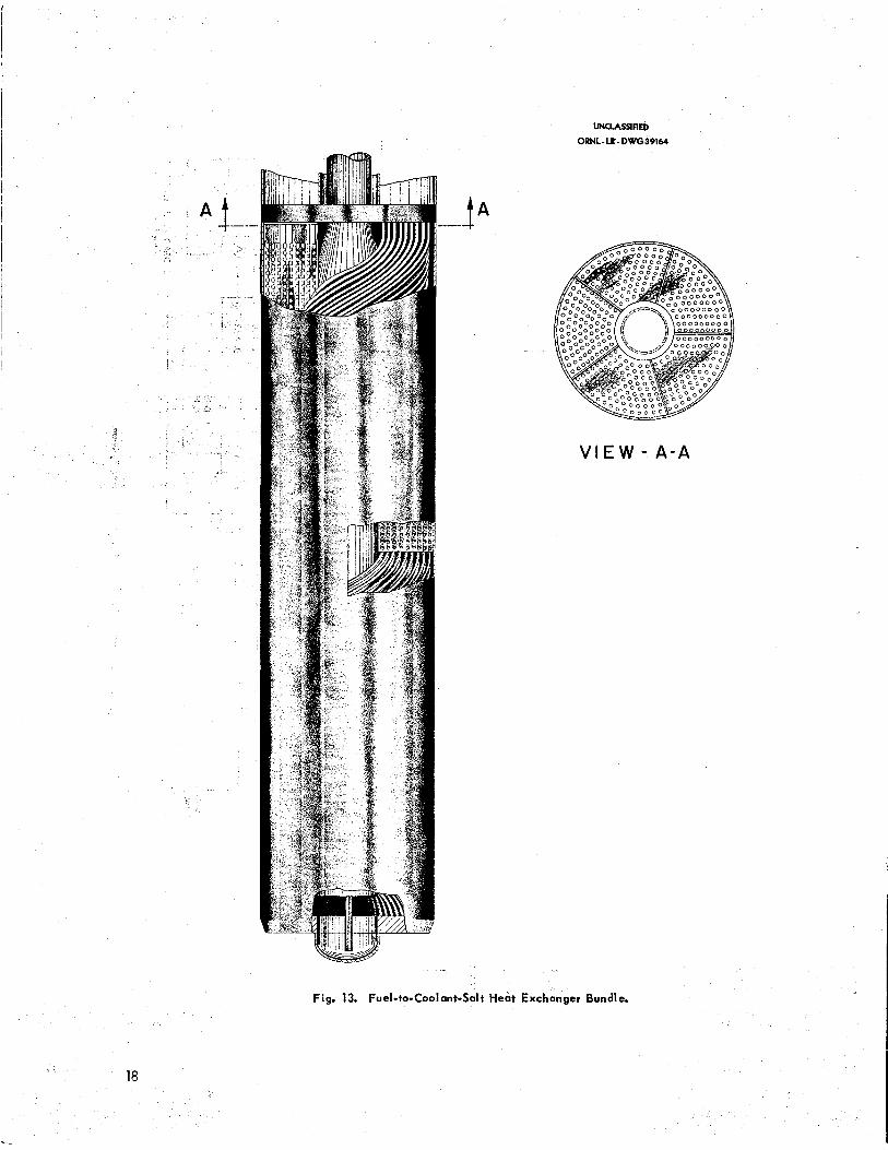
The coolant pump i s of a similar design, modified for operation at a lower radiation level. Since less shielding i s required, the over-ail height of the coolant pump i s less than the height of the fuel pump. Heat i s exchanged from the fuel to the coolant salt in a bayonet-type heat exchanger. The fuel salt i s contained in the tubes, and the flow i s countercurrent. The heat exchanger i s shown in Fig. 13, and the design data are presented in Table 2.
The tubes are coiled i n helices and are located in nine concentric rows around the coolant-salt inlet pipe. The fuel salt enters the upper header from the fuel pump and flows down through the tubes and out of the heat exchanger. The tubes were coiled to reduce the length of the heat exchanger and to increase the flexibil i ty of the tube bund1 e.
Fuel bypass leakage around the heat exchanger i s reduced by a close-fitting section between the heat exchanger outer shell and the reactor weld- ment. Leakage from the top of the heat exchanger
Table 2. Design Data far Heat Exchanger
Fuel sa l t
In out
Flow
Coolant sa l t
In out
F low
Configuration
Flow
Tubes Size
Number Active length Pitch
60 psia, 1 2 3 9 F 25 psia, llO@F 3.30 cfs
90 psia, 1000°F 7 0 psia, 1160°F 2.17 cfs
Multiple coiled helices in mult iple
concentric rings in annular shell
Countercurrent, with fuel sa l t in
tubes
'/,-in. OD, 0.049-in. w a l l 450 12.6 ft
rings
0.875 in. center line to center line,
0.750 in. center line to center line, tubes in rings (normal to tubes)
L a
17
UNUASSIRED ORNL-LR - DWG39164
..: V I E W - A - A
Fig. 13. Fuel-to-Coolant-Salt Heat Exchanger Bundle.
18
c
back into the surge tank i s restricted by a Bel levi Ile-type spring seal between the upper section of the heat exchanger and the fixed inner housing around the exchanger shell. The volume immediately above the fuel inlet header i s part of the fuel off-gas system. Some fuel i s bypassed up into the surge volume and then flows back into the free surface of the expansion tank, where it i s recirculated through the pump.
The coolant salt enters the heat exchanger through the inner tube and flows down the center
nger. This fluid then flows out tube sheet and up through the
heat exchanger on the outdde of the tubes. Five vertical baffles are located on the shell side of the exchanger, so that the coolant salt tends to be directed across the tubes. The coolant the flows across the bottom of the upper tube shee and out of the heat exchbnger in the annular section located on the outside of the inlet pipe. Two thermocouple wells are included in the heat exchanger assembly to measure the fuel temper- ature into and out of the unit. These thermo- couples can be inserted into or withdrawn from the wells from the top of the reactor shield. The entire assembly i s bolted down against a lower
d in the reactor container, and
> - 5
OLANT SALT IN
a seal weld i s made at the very top of the heat exchanger.
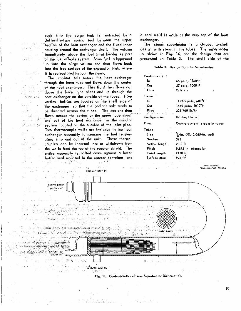
The steam superheater i s a U-tlube, U-shell design with steam in the tubes. The! superheater i s shown in Fig. 14, and the design data are presented in Table 3. The shell side of the
Table 3. Design Data for Superhtrater
Coolant salt
In 65 psia, 116OoF out 37 psia, 1000°F Flow 2.17 cfs
Steam
In 1473.5 psia, 6OO0F out 1450 psia, 10IO°F F l o w 326,700 Ib/hr
Configuration U-tube, U-shell
F low Countercurrent, steam in tubes
Tubes Size %-in. OD, 0.065-in. w a l l Number 31 1 Active length 23.0 ft Pitch 0.875 in. triangular
Total length 7150 ft Surface area 926 ft2
UIKLASSIFIED ORNL--LR-DWG 391694
t n SUPERHEATED
STEAM OUT
t "
Fig. 14. Coolant-Salt---Steam Superheater (Schematic).
19
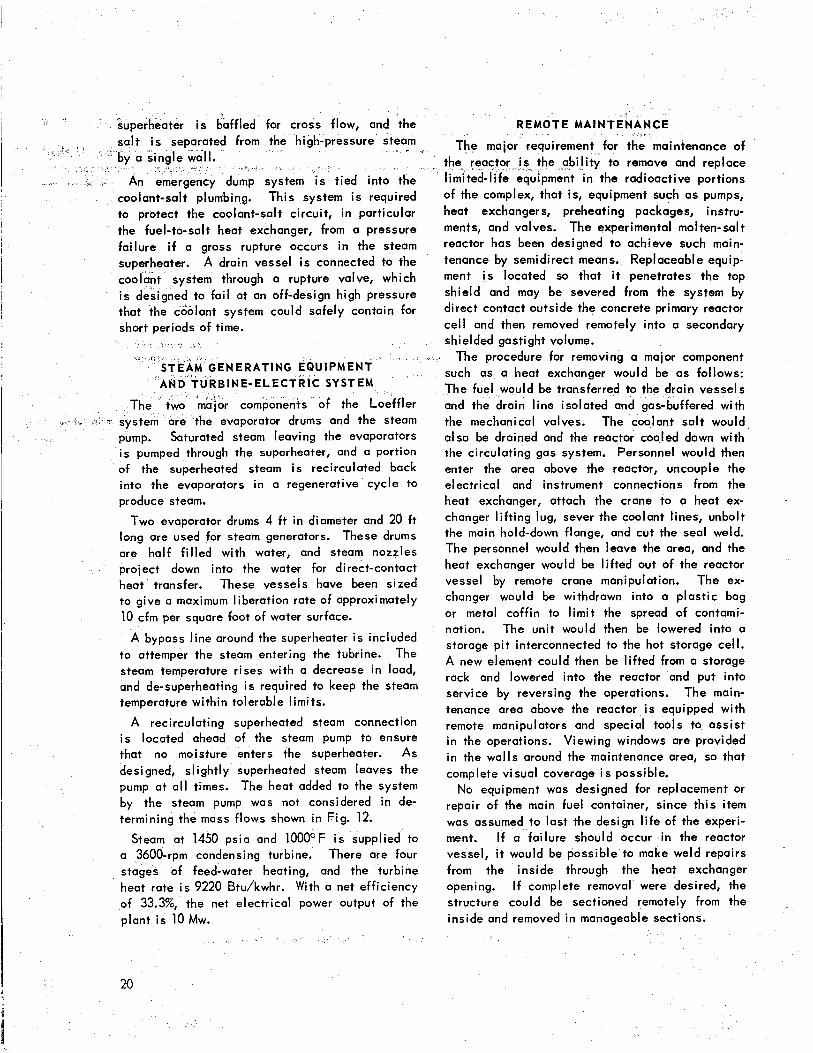
ter i s baffled for cross flow, and 'the REMOTE M A I N T E N A N C E
from the high-pressure ) I * The major requirement for t
em IS tied into coolant-salt plumbing. This system i s required to protect the coolant-salt circuit, in particular the fuel-to-salt heat exchanger, from a pressure failure i f a gross rupture occurs in the steam superheater. A drain vessel i s connected to the coolant system through a rupture valve, which i s designed to fai l at an off-design high pressure that the coolant system could safely contain for
G E N E R A T I N G E Q U I P M E N T A N D T U R B I N E - E L E C T R I C SYSTEM
the evaporator drums and the steam pump. Saturated steam leaving the evaporators i s pumped through the superheater, and a portion of the superheated steam i s recirculated back into the evaporators in a regenerative cycle to produce steam.
Two evaporator drums 4 f t in diameter and 20 ft long are used for steam generators. These drums are half f i l led with water, and steam nozzles project down into the water for direct-contact heat transfer. These vessels have been sized to give a maximum liberation rate of approximately 10 cfm per square foot of water surface.
A bypass line around the superheater i s included to attemper the steam entering the tubrine. The steam temperature rises with a decrease in load, and de-superheating i s required to keep the steam temperature within tolerable limits.
A recirculating superheated steam connection i s located ahead of the steam pump to ensure that no moisture enters the superheater. As designed, slightly superheated steam leaves the pump at al l times. The heat added to the system by the steam pump was not considered in de- termining the mass flows shown in Fig. 12.
Steam at 1450 psia and 1000°F i s supplied to a 3600-rpm condensing turbine. There are four stages of feed-water heating, and the turbine heat rate i s 9220 Btu/kwhr. With a net efficiency of 33.3%, the net electrical power output of the plant i s 10 Mw.
e abil ity to remove and replace ment in the radioactive portions
of the complex, that is, equipment such as pumps, heat exchangers, preheating packages, instru- ments, and valves. The experimental molten-salt reactor has been designed to achieve such main- tenance by semidirect means. Replaceable equip- ment i s located so that it penetrates the top shield and may be severed from the system by direct contact outside the concrete primary reactor cel l and then removed remotely into a secondary shielded gastight volume.
The procedure for removing a major component such as a heat exchanger would be as follows: The fuel would be transferred to the and the drain line isolated and gas-buffered with the mechanical valves. The coolant salt would also be drained and the reactor cooled down with the circulating gas system. Personnel would then enter the area above the reactor, uncouple the electrical and instrument connections from the heat exchanger, attach the crane to a heat ex- changer l i f t ing lug, sever the coolant lines, unbolt the main hold-down flange, and cut the seal weld. The personnel would then leave the area, and the heat exchanger would be l i f ted out of the reactor vessel by remote crane manipulation. The ex- changer would be withdrawn into a plastic bag or metal coffin to l imit the spread of contami- nation. The unit would then be lowered into a storage p i t interconnected to the hot storage cell. A new element could then be l ifted from a storage rack and lowered into the reactor and put into service by reversing the operations. The main- tenance area above the reactor i s equipped with remote manipulators and special tools to assist in the operations. Viewing windows are provided in the walls around the maintenance area, so that complete visual coverage i s possible. No equipment was designed for replacement or
repair of the main fuel container, since this item was assumed to last the design l i fe of the experi- ment. If a failure should occur in the reactor vessel, i t would be possible to make weld repairs from the inside through the heat exchanger opening. If comptete removal were desired, the structure could be sectioned remotely from the inside and removed i n manageable sections.
20
NUCLEAR PERFORMANCE
The details of the core design (Fig. 1) were modified slightly for the purpose of evaluating the nuclear performance. The fuel i s considered to be contained in a quasi-spherical INOR-8 vessel having a diameter of 72 in. and a wall P2 in. thick. The cwe i s surrounded by a neutron and gamma-ray “thermal” shield consisting of the following annular regions: a gas annulus 3 in. thick through which dry air or nitrogen may be circulated to preheat the shell during startup or to cool i t during operation; a 6-in. layer of aluminum silicate insulation (6 Ib/ft3); a 2-in. layer of ordinary steel; a 4-in. layer of organic coolant (diphenyl or related compounds); and four successive 2-in. layers of boron steel (1% B) separated by four 4-in. layers of organic coolant. Draining the organic coolant from the first layer (adjacent to the ordinary steel) w i l l result in a reactivity decrease (1.89%) expected to be suffi- cient for emergency shutdown.
The fuel carrier consists of a mixture of LiF (63 mole %) and BeF2 (37 mole Sl) having a liquidus temperature of 860OF and an estimated density of 1.9 dcm3. The critical concentration of 0235 (as UF,) i s estimated to be 3.25 x 10¹⁹ atoms/cm3 (0.1 mole Sl), giving a critical mass of 40.6 kg and a critical inventory of 65.8 kg for a total fuel volume of 171 ft3. For purposes of the nuclear calculation, the effect of the fuel in the inlet-outlet duct was ignored; thus the critical concentration estimated i s probably somewhat high. The nonsphericity of the thermal shield was also ignored. The Oracle codes Cornpone and Sorghum were used for criticality and l i fet ime cal cul ations, respectively.
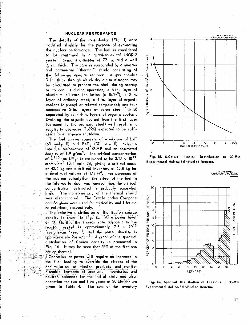
The relative distribution of the fission source g. 15. At a power level
the fission rate adjacent to the i s approximately 7.5 x 10”
ec-’, and the power density i s .4 w/cm3. A graph of the spectral
distribution of fission density i s presented in 16. It may be seen that 55% of the fissions
ration at power Will require an increase in the fuel loading to override the effects of the
operation for two and five years at 30 Mw(th) are given in Table 4. The sum of the inventory
-
Rf
UNCLASSIFIED ORNL-LR-DWG 43508
4 5 6 7 ( X l C US CUBED (cm3)
Fig. 15. Relative Fission Distribution in 30-Mw Experimental Mol ten-Sol t- Fuel ed Reactor.
UNCLASSIFIED ORIUL-LR- DWG 43509 r
20
>- 18
a I 46
k
(3 IT
I- W -1
z 3
14
12 E5 n !g? 10 0 E 8 cn LL
8 6 c z W 0 4 IT W a 2
n 0 2 4 6 8 40 12 14 16 18
LETHARGY
Fig. 16. Spectral Distribution of Fissions in 30-Mw Experimental Molten-Salt-Fueled Reactor.
21

a
W
0
z
t
22

increase and burnup of U235 amounts to 70 kg during two years of operation.
In the init ial state, the neutron leakage from the spherical thermal shield amounts to about IO* neutrons-cm-2*sec-1 at a power level of 30 Mw(th). The spectral distribution of these neutrons i s shown gra
'-1
26
24
22
a E 48 -I
5 46 2
a: W a 44
$ 6 a
4
2
n
UNCLASSIFIED ORNL-LR-DWG 43510
> I a: W a
a: W &
z 2 a I
a LL 0 z + V 4 a: L
0
UNCLASSIFIED ORNL-LR-DWG 43511
40
1 w 10-4
0 1 2 3 4 5 6 7 8 9 IO ( 1 12 GAMMA-RAY ENERGY (Mevl
Fig. 18. Spectral Distribution of Gamma Energy Leaking Through Core Vesse l in 30-Alw Molten-Salt-
Fueled Reactor. i 0 2 4 6 8 (0 42 44 I6 18 20 i
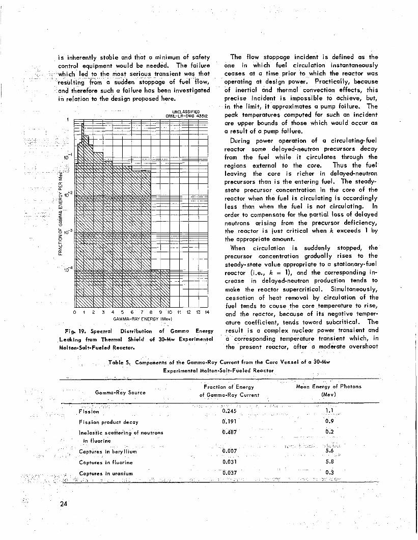
Table 5. It may be seen that the major source of gamma rays i s inelastic scattering of neutrons by fluorine. These gamma rays ore, however,
i relatively low i n energy. The fission and fission-
oduct-decay gamma rays wi II probably provide e major biological shielding problern.
LETHARGY
R E A C T O R H A Z A R D S
1 Exhaustive studies of the effects of nuclear , nsients induced by off-design operation or
lfunctioning and breakdown of equipment of distribution i s shown graphically in Fig. 18. molten-salt-fueled reactors of this general design
have not yet been made but must, of course, be i s substantial. It ted completed before a design i s approved for con- current leaking fro al struction. Exploratory studies .were made of a
d would not exceed 0.001 w/cm2. The generally similar reactor of 60@Mw(ih) capocityt4 and it was tentatively concluded that the reactor
e attenuation of this gamma-ray current in the
estimated spectral distribution i s given in Fig. 19.
A breakdown of the gamma-ray escape-current energy in terms of gamma-ray sources i s given in
G . MacPherson et al., Molten-Salt Reactor Pro ram Status Report, ORNL-2634, p 42-59 (Mov. 12, 1458).
23
i s inherently stable and that a minimum of safety control equipment would be needed. The failure
d to the most ser grim a sudden
and therefore such a failure has been investigated i n relation to the design proposed here.
UNCLASSIFIEG ORNL-LR-DWG 43512
0 1 2 3 4 5 6 7 8 9 1 0 1 1 1 2 1 3 1 4 GAMMA-RAY ENERGY (MeV)
Fig. 19. Spectral Distribution of Gamma Energy
Leaking from Thermal Shield of 30-Mw Experimental
Molten-Sal t-Fuel ed Reactor.
The flow stoppage incident i s defined as the one in which fuel circulation instantaneously ceases at a time prior to which the reactor was operating at design power. Practically, because of inertial and thermal convection effects, this precise incident i s impossible to achieve, but, in the l imi t , i t approximates a pump failure. The peak temperatures computed for such an incident are upper bounds of those which would occur as a result of a pump failure.
During power operation of a circulating-fuel reactor some delayed-neutron precursors decay from the fuel while it circulates through the regions external to the core. Thus the fuel leaving the core i s richer in delayed-neutron precursors than i s the entering fuel. The steady- state precursor concentration in the core of the reactor when the fuel i s circulating i s accordingly less than when the fuel i s not circulating. In order to compensate for the partial loss of delayed neutrons arising from the precursor deficiency, the reactor i s just critical when k exceeds 1 by the appropriate amount.
When circulation i s suddenly stopped, the precursor concentration gradually rises to the steady-state value appropriate to a stationary-fuel reactor (i.e., k = l ) , and the corresponding in- crease in delayed-neutron production tends to make the reactor supercritical. Simultaneously, cessation of heat removal by circulation of the fuel tends to cause the core temperature to rise, and the reactor, because of i t s negative temper- ature coefficient, tends toward subcritical. The result i s a complex nuclear power transient and a corresponding temperature transient which, in the present reactor, after a moderate overshoot
le 5. Components of the Gamma-Ray Current from the Core Vessel of a 30-Mw
Gamma-Ray Source
Fission product decay
Inelastic scattering of neutrons 0.487 0.2
tures in beryllium
Captures in fluorine 0.031
0.037 0.3

finally settles down to a higher critical temper- ature.
The above-described transient was studied for the present reactor with the aid of the ORNL Analog Computer Facility, using methods de- scribed by C. s. W ~ l k e r . ~ The pertinent pa- rameters that were used to describe the reactor and the computed effect on the critical temperature are given below:
"235 Fuel
Spherical core volume 113.2 ft3
External fuel volume 57.5 ft3
Fuel circulation rote 3.18 cfs
Volumetric heat capacity of fuel
Design power ( init ial condition)
Nuclear temperature coefficient -6.75 x per OF
64 B t ~ . f t - ~ . r F ) - '
30 Mw
of reactivi ty
Prompt-neutron lifetime 8.8 x sec
Rise in criticol temperature 19.5OF (computed)
As expected, for the case in which no heat escapes from the core, the temperature rises asymptotically to a maximum, where i t remains indefinitely, maintaining the reactor in a sub- critical condition. The temperature rises about 35OF in the first TO sec, and the total rise in temperature is less than 110OF; 90% of the
maximum i s reached 90 sec after the start of the transient. Nuclear afterheat was not taken into account in the above calculations, and, of course, in any real reactor the temperature would not be
but would continue to rise because
during a prolonged stoppage of fuel circulation, afterheat must be removed by some alternative means. In general, i f the removal rate i s a fraction of the init ial reactor power and exceeds the afterheat production rate, instantaneous stoppage of circulation w i l l result in an init ial temperature rise followed by
stagnant-mean core-critical temperature i s 19.8OF above the circulating-mean core-critical temper- ature.
To gain insight into the maximum temperatures which might be attained and the tirnes to reach them, the behavior of the reactor was investigated under a condition of auriliary cooling wherein the cooling rate less the afterheat rate was held constant and the fuel circulation was instan- taneously stopped. The peak temperatures and times to reach them as a function of the assumed power-removal rate (in excess of thai required for afterheat), which i s constant throughout the transient, are indicated in Fig. 20. A s expected, the peak temperatures and times to reach them decrease with increasing power-removal rates.
UNCLPSSIFIED ORNL-L.R-OWG 43543
PEAK TEMPERATURE Isec) IO0 IO0 - "
VI PEAK MEAN COR
2
!2
5
W
= 80 W
? 60
=. 2 40 X
0 c W I I- 2 0
0
I
80
'" LT W a:
4 U W
60 2
5 40 ,-
20
0 0 5 to 15
CONSTANT POWER REMOVAL(Mw1
(IN EXCESS OF THAT REQUIRED FOR REMOVAL OF AFTERHEAT)
Fig. 20. Effect of Instantaneous Reduction of Heat Flow from Reactor on Temperatures.
The init ial rate of rise, which is important for thermal shock considerations, i s very modest, as shown by the curve giving the rise in the first 10-sec period. Oscillations about the new critical temperature are we1 I damped; the damping in- creases and the times between peaks decrease with increasing power-removal ,rates. Typically,
a fall. After perhaps oscillating a few times, w i l l settle on the new critical
for 3 Mw heat removal, the first maximum occurs in 82 sec following initiation of *the transient,
31, 1958). ature); the second maximum occurs 9 min after
' c . s. Walker, %i77ZZdUti072 Of the ORSORT Buttermilk with a 5 5 0 ~ peak (obove the new critical temper- Reactor, Loss of Fuel Flow, ORNL CF-58-7-64 (July
1
25

initiation of the transient, with a 5OF peak. It COSTS i s clear that, i f need be, ample time i s available to adjust heat-removal rates to near the afterheat An estimate of construction costs has been
order to maintain the reactor above prepared and i s presented in Table 6. It was concluded that the plant could be built for about
afterheat i s $16,000,000. Primary emphasis was placed on hence, subcritical
310
3 12
Land and land rights N o cost
Structures and improvements
$ 10,000 160,000
Station buildings
Reactor bui ld ing
Turbine-generator bui ld ing
Tota l structures and improvements
Reactor and steam-generating equipment
Primary system
Fue l container and gas shroud
Pumps and pump drive
Primary heat exchanger
Subtota I
Primary system auxi l iar ies
Fue l drain and storage
Enriching and sampling system
Purge system
Off-gas and effluent system
Inert-gas system
Other auxil iary systems
600,000 800,000
275,000 250,000 150,000
$ 675,000
2 18,000 100,000 50,000
150,000 50,000 50,000
$1,570,000
Subtotal $ 618,000
Intermediate system
Pump and pump drive 150,000 Superheater 194,000 Drain system 50,000
Emergency dump system 75,000 Other intermediate system equipment 50,000
Piping and valves 100,000
Subto
Reactor cel l : shielding and containment
Heating, cooiing, and vent i lat ing systems
Reactor primary heating and cool ing system
Ce l l cooling and vent i lat ing system
Stack 15,000
50,000 ediate heating system
Subtota I $ 215,000
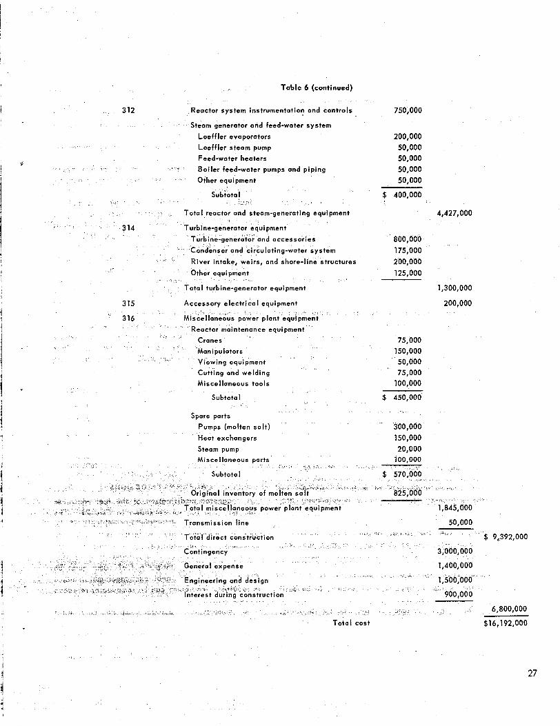
Table 6 (continued)
312 Reactor system instrumentation and controls 750,000
Steam generator and feed-water system
Loeff ler evaporators
Loeff ler steam pump
Feed-water heaters
Boiler feed-water pumps and piping
Other equipment
nser and circulating-water system
Other equipment
Total turbine-generator equipment
315 Accessory electr ical equipment
wer plant equipmen
Reactor maintenance equipment
Viewing equipment
Cutting and welding
Miscellaneous tools
Subtotal
200,000 50,000 50,000 50,000 50,000
$ 400,000
800,000 175,000 200,000 125,000
4,427,000
1,300,000
200,000
75,000 150,000 50,000 75,000
100,000
$ 450,000
Spare parts
Pumps (molten sal t ) 300,000 Heat exchangers 150,000
20,000 Steam pump Miscellaneous ports 100,000
Toto1 cost
3,000,000
1,400,000
6,800,000
$16,192,000
27
! components of the molten- o l t system Thes f items made up the more unique portions of the 1 plant and, in an over-all analysis, were subject
to the greatest estimating errors. I 1 Most of the design time was concentrated on 1 the major components of the salt systems to
facilitate cost estimating. Engineering layouts ! were prepared of the fuel container, heat ex-
changer, and superheaters. These drawings were reviewed by the Y-12 shop personnel for fab-
1
!
ricabi l i ty and first estimates of manufacturing time. This group has had considerable experience in nickel-base alloy fabrication, and they have bui It reactor-grade components. In addition, several outside fabricators were asked to review the drawings from the standpoint of>design and fabr ico bi I ity.
Many constructive comments were obtained from these reviews, but no serious objection with regard to concept or design was raised which would invalidate the system or seriously change the manufacturing estimates. Some development work would be required in the tube fabrication of the fuel-to-coolant-salt bayonet heat exchanger, and test work would be required to check out some of the welding and brazing on the major INOR-8 components.
The finished INOR-8 components in the plant were estimated to weigh approximately 50,000 Ib. Most of the material required to fabricate these components would be in the form of plate and tubing. Foci l i t ies for supplying INOR-8 stock are available, and a sizable inventory i s currently on hand. The raw-material prices used were obtained from vendors’ estimates on sizes and quantities needed for the experimental reactor and from actual costs of material received for the molten-salt-fueled reactor development pro- gram.
The reactor buildings and site were not suffi- x ient ly specified to get complete cost information. A site was chosen near an area that had been studied for a similar reactor installation, and estimates for site improvement and facilities were available. No cost was applied to land acqui- sition, since the reoctor was assumed to be built in the Oak Ridge area.
The gross volume of the reactor building, offices, hot cells, laboratories, and control room was estimated at 200,OOO ft3. The turbine- generator building was calculated to have a volume I of 400,000 ft3.
28
The cost of most of the auxiliary systems was estimated without detai I. These systems, or subsystems, were estimated as gross packages on the basis of general experience. One exception was the reactor heater-cooler unit, which was developed to the point of engineering layout and specification of the major components.
The more conventional portions of “the steam generator plant were determined from manufac- turers’ data.
Included in the first plant cost was the molten- salt inventory. This quantity included a spare fuel volume and 50% overage for the coolant-salt volume, resulting in a total of 550 ft3. This entire quantity was assumed to contain Li’ at the 99.99% assay level, which contributes one- third of the total cost of $1500 per cubic foot.
An over-all contingency factor of approximately 30% of the first cost was used, and the other indirect costs were set at values considered applicable to this type of construction.
The operating costs for the system were studied. After the completion of shakedown and planned experiments, i t was concluded that the plant could be operated for $635,000 a year. The breakdown of this estimate is as follows:
Wages (including supervision) $250,000
Supplies 10,000
Mointenance 75,000
270,000 Fuel burnup and inventory charge
Fuel preparotion 30,000
$635,000
ALTERNATE DESIGNS
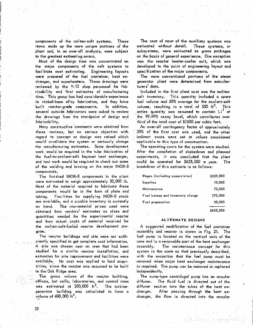
A suggested modification of the fuel container assembly and reactor i s shown in Fig. 21. The fuel pump i s located on the vertical axis of the core and i s a removable part of the heat exchanger assembly. The maintenance concept for th is system i s the same as that previously described, with the exception that the fuel pump must be removed when major heat exchanger maintenance i s required. The pump can be removed or replaced independently.
The sump-type centrifugal pump has an annular diffuser. The fluid fuel i s directed out of the diffuser section into the tubes of the heat ex- changer. After passing through the heat ex- changer, the flow i s directed into the annular
I
I I
r
UNCLASSIFIED ORNL-LR-DWG 43514
- GAS-DUCT OUTLET
4CTOR
\
GAS-DUCT INLET
Fig. 21. Concentric-Pump Molten-Salt-Fueled Reactor Layout.
29
volume surrounding the reactor and then dis- charged up into the core at the bottom opening. The fuel leaves the core at the top and goes vertically up into the pump section. The fuel expansion tank surrounds the pump barrel and i s cooled by the intermediate salt circuit.
The coolant salt enters the heat exchanger shell at the bottom and flows upward around the tubes. After it leaves the heat exchanger it passes around the pump region and out of the assembly. This arrangement has several important advan- tages. The primary fuel container geometry i s simplified, and the support problem i s more straightforward. The fuel inventory i s reduced, and the expansion tank region i s completely surrounded by coolant to ensure more positive temperatur'e*control of this region.
The major disadvantage of the concept i s the more complicated heat exchanger upper structure. This region, as presently conceived, includes the stationary parts of the pump assembly, which would be discorded in the event of a heat ex- changer failure. Even so, this concept does render more of the fuel system components readily replaceable and would simplify the operations required to remove the entire fuel container from the reactor cell. This fuel system i s sufficiently attractive to warrant further design study.
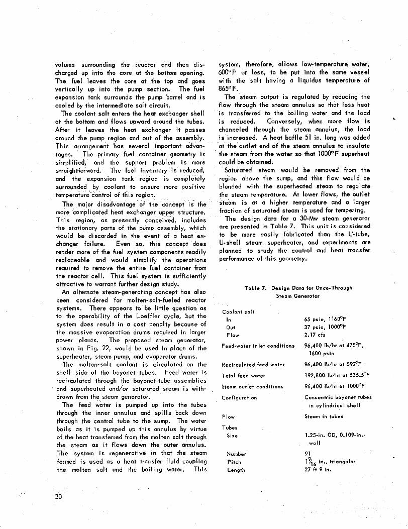
An alternate steam-generating concept has al so been considered for molten-salt-fueled reactor systems. There appears to be l i t t le question as to the operability of the Loeffler cycle, but the system does result in a cost penalty because of the massive evaporation drums required in larger power plants. The proposed steam generator, shown in Fig. 22, would be used in place of the superheater, steam pump, and evaporator drums.
The molten-salt coolant i s circulated on the shell side of the bayonet tubes. Feed water i s reci rcu I ated through the bayonet-tube assembl ies and superheated and/or saturated steam i s with- drawn from the steam generator.
The feed water i s pumped up into the tubes through the inner annulus and spills back down through the central tube to the sump. The water boils as it i s pumped up this annulus by virtue of the heat transferred from the molten salt through the steam as i t flows down the outer annulus. The system i s regenerative in that the steam formed i s used as a heat transfer fluid coupling the molten salt and the boiling water. This
system, therefore, allows low-temperature water, 600°F or less, to be put into the same vessel wi th the salt having a liquidus temperature of 865" F.
The steam output i s regulated by reducing the flow through the steam annulus so that less heat i s transferred to the boiling water and the load is reduced. Conversely, when more flow i s channeled through the steam annulus, the load i s increased. A heat baffle 51 in. long was added at the outlet end of the steam annulus to insulate the steam from the water so that 1OOOOF superheat could be obtained.
Saturated steam would be removed from the region above the sump, and this flow would be blended with the superheated steam to regulate the steam temperature. At lower flows, the outlet steam i s at a higher temperature and a larger fraction of saturated steam i s used for tempering.
The design data for a 30-Mw steam generator are presented in Table 7. This unit i s considered to be more easily fabricated than the U-tube, U-she1 I steam superheater, and experiments are planned to study the control and heat transfer performance of this geometry.
k
Table 7. Design Data for Once-Through Steam Generator
Coolant sa l t
In out Flow
Feed-water inlet conditions
Recirculated feed water
Total feed water
Steam outlet conditions
Configuration
Flow
Tubes Size
Number Pitch Length
65 psia, 1160°F 37 psia, 1000°F 2.17 cfs
96,400 Ib/hr a t 475"F, 1600 psi0
96,400 Ib/hr a t 592°F
192,800 Ib/hr at 535.5"F
96,400 Ib/hr at 1000°F
Concentric bayonet tubes in cylindrical shell
Steam in tubes
1.25-in. OD, 0.109-in.- w o l l
91 1Y16 in., triangular
27 ft 9 in.
30

. .
. ,
," .i-
- . .
SUPERHEATED
WATER AND STEAM
SECTION THROUGH TUBE ASSEMBLY
SALT IN-
SUPERHEATED STEAM OUT-
FEED WATER IN-
UNCLASSIFIED ORNL-LR-DWG 39t68A
!ATE0 t
Fig. 22. Once-Through Steam Generotor.
WATER OUT
31
It was previously mentioned that unclad graphite modified and a graphite moderator incorporated. was being investigated for use in molten-salt Neither of these approaches would alter the basic breeder reactors. Graphite test specimens could fuel container concept, and the latter would result be inserted in the core of this reactor without in a system with a much smaller l iquid inventory
e core could be and probably a smaller core vessel. mplication, or th
c
LIST OF DRAWINGS
A l i s t of ORNL drawings that were prepared for this design study i s presented below:
T i t l e ORNL Drawing No.
Plant Section Looking West F-2 -02-054-7942
I orth F-2-02-054-7943
I
i
I Plan - Elevation 838 -02-054-7938
F-2-02-054-794 1
F-2-02-054-7939 I
I Fuel Container Weldment F-2-02-054-7940
Fuel-to-Coolant-Salt Heat Exchanger F-2-02-054-7972
Reactor and Ce l l
Steam Superheater
Bayonet Tube Boiler-Superheater
Reactor Heater-Cooler Assembly
Concentric Reactor Assembly
Enricher Sampler Assembly
F -2-02-054-7897
F-2-02-054-7928
F-2-02-054-9057
F -2-02-054-9028
F -2-02-054-7657
Enricher Sampler Assembly F-2-02-054-7658
Preliminary Site F-2-02-054-7944
Perspective, S. W. Corner D -2 -02 -054 -7945
Perspective, S. E. Corner D-2-02-054-7946
Perspective, N. E. Corner D-2-02-054-7947
UC-81 Reocitors - Power TID-4500 (15th ed.)
INTERNAL DISTRIBUTION
1. R. G. Affel 2. L. G. Alexander 3. E. S. Bettis 4. D. S. Billington 5. F. F. Blankenship 6. E. P. Blizard 7. A. L. Boch 8. C. J. Borkowski 9. W. F. Boudreau
10. G. E. Boyd 11. M. A. Bredig 12. E. J. Breeding 13. R. B. Briggs 14. W. E. Browning 15. D. 0. Campbell 16. W. H. Carr 17. G. 1. Cathers 18. C. E. Center (K-25) 19. R. A. Charpie 20. J. H. Coobs 21. F. L. Culler 22. J. H. Devon 23. D. A. Douglas 24. L. 8. Emlet (K-25) 25. W. K. Ergen 26. J. Y. Estabrook 27. D. E. Ferguson 28. A. P. Fraas 29. E. A. Franco-Ferreira 30. J. H. Frye, Jr. 31. W. R. Gall 32. A. T. Gresky 33. J. L. Gregg
4-36. W. R. Grimes 37. E. Guth 38. C. S. Harrill 39. M. R. H i l l 40. H. W. Hoffman . A. Hollaender . A. S. Householder . W. H. Jordan . G. W. Keilholtz . C. P. Keim 46. M. T. Kelley 47. F. Kertesz 48. B. W. Kinyon
49. M. E. Lackey 50. J. A. Lane 51. R. S. Livingston 52. H. G. MacPherson 53. R. E. MacPherson 54. W. D. Manly 55. E. R. Mann 56. L. A. Mann 57. W. B. McDonald 58. H. F. McDuffie 59. J. R. McNally 60. H. J. Metz 61. R. P. Milford 62. E. C. Miller 63. J. W. Miller 64. K. Z. Morgan 65. J. P. Murray (Y-12) 66. M. L. Nelson 67. G. J. Nessle 68. W. R. Osborn 69. P. Patriarca 70. A. M. Perry 71. D. Phillips 72. P. M. Reyling 73. J. T. Roberts 74. M. T. Robinson 75. H. W. Savage 76. A. W. Savolainen 77. J. L. Scott 78. H. E. Seagren 79. E. D. Shipley 80. M. J. Skinner 81. A. H. Snell 82. E. Storto 83. C. D. Susano 84. J. A. Swartout 85. A. Taboada 86. E. H. Taylor 87. R. E. Thoma 88. D. 8. Trauger 89. F. C. VonderLage 90. G. M. Watson 91. A. M. Weinberg 92. M. E. Whatley 93. J. C. White 94. G. D. Whitman
33

95. G. C. Williams 102-121. Laboratory Records Department 96. C. E. Winters 122. Laboratory Records, ORNL R.C. 97. J. Zasler 123-124. Central Research Library
98-101. ORNL - Y-12 Technical Library, Document Reference Section
EXTERNAL DlSTRlBUTlON
-125. D. H. Groelsema, AEC, Washington 126. Division of Research and Development, AEC, OR0
127-710. Given distribution as shown in TID-4500 (15th ed.) under Reactors - Power category (75 copies - OTS)
34