ORIGINAL ARTICLE Punching shear strength of waffle flat slabs
14
Rev. IBRACON Estrut. Mater., vol. 14, no. 1, e14106, 2021 ORIGINAL ARTICLE Corresponding author: Ricardo José Carvalho Silva. E-mail: [email protected] Financial support: None. Conflict of interest: Nothing to declare. This is an Open Access article distributed under the terms of the Creative Commons Attribution License, which permits unrestricted use, distribution, and reproduction in any medium, provided the original work is properly cited. Rev. IBRACON Estrut. Mater., vol. 14, no. 1, e14106, 2021| https://doi.org/10.1590/S1983-41952021000100006 1/14 Received 07 January 2020 Accepted 25 May 2020 Punching shear strength of waffle flat slabs Estudo da resistência à punção em lajes lisas nervuradas Ricardo José Carvalho Silva a Dênio Ramam Carvalho de Oliveira b Nívea Gabriela Benevides de Albuquerque b Francisco Eudázio Suriano da Silva Júnior a Felipe da Silva Leite b a Universidade Estadual do Vale do Acaraú – UVA, Faculdade de Engenharia Civil, Sobral, CE, Brasil b Universidade Federal do Pará – UFPA, Faculdade de Engenharia Civil, Belém, PA, Brasil Abstract: This research aimed to compare the ultimate load of 10 waffle flat slabs with different sizes of solid area and spacing between ribs. For this, a non-linear computational simulation of the slabs was carried out until their failure using the engineering software ANSYS. The failure modes and loads were analyzed, and the results showed that the models with less solid area presented less bearing capacity in comparison to the models with greater solid area when the failure mode was shearing of the ribs. The slabs with the largest solid regions experienced punching shear and behaved in a similar way as solid flat slabs, indicating compliance with the codes in relation to their punching shear strength provisions, especially with the NBR 6118. The results show that a square solid area whose length is 15% of the span is reasonable and that the ACI, Eurocode 2 and NBR 6118 provisions underestimate the shear strength of the ribs. Keywords: waffle flat slab, punching shear, solid area, Ansys. Resumo: Esta pesquisa teve o objetivo de comparar computacionalmente a resistência de 10 lajes lisas nervuradas com diferentes tamanhos de área maciça e diferentes espaçamentos das nervuras. Para isso, os ensaios das lajes foram simulados no programa computacional ANSYS até a ruptura. Foram observados os modos e as cargas de ruptura, e, através dos resultados, observou-se que os modelos com menor região maciça apresentaram menor resistência em comparação aos modelos de maior área maciça, pois sua ruptura se deu por cisalhamento nas nervuras. As lajes com maiores regiões maciças sofreram punção e se comportaram de forma semelhante a lajes lisas maciças, apresentando conformidade com as normas em relação às suas estimativas de resistência à punção, especialmente com a NBR 6118. Desta forma, a regra prática de se determinar a região maciça com 15% do vão se mostrou razoável, e observou-se que o ACI, o Eurocode 2 e a NBR 6118 subestimam as resistências ao cisalhamento das nervuras. Palavras-chave: laje lisa nervurada, punção, área maciça, Ansys. How to cite: R. J. C. Silva, D. R. C. Oliveira, N. G. B. Albuquerque, F. E. S. Silva Júnior, and F. S. Leite, “Punching shear strength of waffle flat slabs,” Rev. IBRACON Estrut. Mater., vol. 14, no. 1, e14106, 2021, https://doi.org/10.1590/S1983-41952021000100006 1 INTRODUCTION Punching shear is a type of brittle failure that occurs in slabs supported directly on a column and when flexural strength of the slab is greater than its shear strength. This type of failure can lead to progressive collapse of the structure. Currently, the waffle slab system without beams and with a solid area around the column is one of the most used structural system in Brazil. The simplicity of the construction of this system and the lesser use of concrete in relationship to that of the solid flat slab made this type of slab popular for construction of medium height and tall buildings.
Transcript of ORIGINAL ARTICLE Punching shear strength of waffle flat slabs
Rev. IBRACON Estrut. Mater., vol. 14, no. 1, e14106, 2021
ORIGINAL ARTICLE
Corresponding author: Ricardo José Carvalho Silva. E-mail: [email protected] Financial support: None. Conflict of interest: Nothing to declare.
This is an Open Access article distributed under the terms of the Creative Commons Attribution License, which permits unrestricted use, distribution, and reproduction in any medium, provided the original work is properly cited.
Rev. IBRACON Estrut. Mater., vol. 14, no. 1, e14106, 2021| https://doi.org/10.1590/S1983-41952021000100006 1/14
Received 07 January 2020 Accepted 25 May 2020
Punching shear strength of waffle flat slabs Estudo da resistência à punção em lajes lisas nervuradas Ricardo José Carvalho Silvaa Dênio Ramam Carvalho de Oliveirab Nívea Gabriela Benevides de Albuquerqueb Francisco Eudázio Suriano da Silva Júniora Felipe da Silva Leiteb
aUniversidade Estadual do Vale do Acaraú – UVA, Faculdade de Engenharia Civil, Sobral, CE, Brasil bUniversidade Federal do Pará – UFPA, Faculdade de Engenharia Civil, Belém, PA, Brasil
Abstract: This research aimed to compare the ultimate load of 10 waffle flat slabs with different sizes of solid area and spacing between ribs. For this, a non-linear computational simulation of the slabs was carried out until their failure using the engineering software ANSYS. The failure modes and loads were analyzed, and the results showed that the models with less solid area presented less bearing capacity in comparison to the models with greater solid area when the failure mode was shearing of the ribs. The slabs with the largest solid regions experienced punching shear and behaved in a similar way as solid flat slabs, indicating compliance with the codes in relation to their punching shear strength provisions, especially with the NBR 6118. The results show that a square solid area whose length is 15% of the span is reasonable and that the ACI, Eurocode 2 and NBR 6118 provisions underestimate the shear strength of the ribs.
Keywords: waffle flat slab, punching shear, solid area, Ansys.
Resumo: Esta pesquisa teve o objetivo de comparar computacionalmente a resistência de 10 lajes lisas nervuradas com diferentes tamanhos de área maciça e diferentes espaçamentos das nervuras. Para isso, os ensaios das lajes foram simulados no programa computacional ANSYS até a ruptura. Foram observados os modos e as cargas de ruptura, e, através dos resultados, observou-se que os modelos com menor região maciça apresentaram menor resistência em comparação aos modelos de maior área maciça, pois sua ruptura se deu por cisalhamento nas nervuras. As lajes com maiores regiões maciças sofreram punção e se comportaram de forma semelhante a lajes lisas maciças, apresentando conformidade com as normas em relação às suas estimativas de resistência à punção, especialmente com a NBR 6118. Desta forma, a regra prática de se determinar a região maciça com 15% do vão se mostrou razoável, e observou-se que o ACI, o Eurocode 2 e a NBR 6118 subestimam as resistências ao cisalhamento das nervuras.
Palavras-chave: laje lisa nervurada, punção, área maciça, Ansys.
How to cite: R. J. C. Silva, D. R. C. Oliveira, N. G. B. Albuquerque, F. E. S. Silva Júnior, and F. S. Leite, “Punching shear strength of waffle flat slabs,” Rev. IBRACON Estrut. Mater., vol. 14, no. 1, e14106, 2021, https://doi.org/10.1590/S1983-41952021000100006
1 INTRODUCTION Punching shear is a type of brittle failure that occurs in slabs supported directly on a column and when flexural
strength of the slab is greater than its shear strength. This type of failure can lead to progressive collapse of the structure. Currently, the waffle slab system without beams and with a solid area around the column is one of the most used
structural system in Brazil. The simplicity of the construction of this system and the lesser use of concrete in relationship to that of the solid flat slab made this type of slab popular for construction of medium height and tall buildings.
R. J. C. Silva, D. R. C. Oliveira, N. G. B. Albuquerque, F. E. S. Silva Júnior, and F. S. Leite
Rev. IBRACON Estrut. Mater., vol. 14, no. 1, e14106, 2021 2/14
However, the strength of the waffle flat slab is directly linked to the size of the solid area around the column and very small areas can promote the formation of the punching shear cone beyond the solid area and induce shearing of the ribs.
Al-Bayati et al. [1], [2], Arunkumar et al. [3] and Sacramento et al. [4] observed that some tested waffle slabs had their strength reduced when the punching shear cone reached the ribbed region. That is, in order to avoid a bearing capacity reduction of the slab, it is of fundamental importance that the punching shear cone is located within the solid area of the slab. The problem is that NBR 6118 [5], EC2 [6] and ACI 318 [7] are silent on this point. These codes don’t have any recommendation to the dimension of this solid area. Although there is no normative prescription, it is common among designers to adopt the dimensions of the solid area to be around 15% of the span in each direction.
1.1 Objective The aim of this work was to investigate, using the Ansys computer program, the ultimate strength and the failure
mode of waffle flat slabs without shear reinforcement and with a solid area of different sizes around the column. In addition, the size of the solid area around the column was also correlated with the failure mode (Punching shear in the solid area or Shearing of the ribs with the punching shear cone extending beyond the solid area).
1.2 Justification Experimental studies such as those by Al-Bayati et al. [1], [2], Arunkumar et al. [3] and Sacramento et al. [4]
showed that the reduction of the solid area in waffle flat slabs can reduce their ultimate strength, leading to the punching shear cone extending beyond the solid area. There is a rule of thumb among designers to use the length of the solid area to be at least equal to 15% of the clear span between columns, but there is no scientific basis for this rule.
Building codes are silent on the subject on the dimensions of the solid area around the column, as well as not providing clear methods to determine the punching shear strength of this type of slab. The only specific recommendation concerns the necessity to check the shear capacity of the ribs, and this recommendation is significantly conservative.
With so many uncertainties and omissions on this subject by the codes, the study of waffle flat slabs has great relevance. The subject is still of great technical and scientific importance, given the existing knowledge gap.
The research presented herein is fundamentally computational, although 2 experimental results from Albuquerque and Oliveira [8] have been used to validate the numerical models.
2 CODE RECOMMENDATIONS The ACI 318 [7], Eurocode 2 [6] and NBR 6118 [5] formulations are presented below, with the safety factors
removed, in order to compare the calculated values to the computational results.
2.1 ACI 318 [7] According to the American code, the estimated punching shear load (VACI, p), for slabs without shear reinforcement,
is the lowest among Equations 1, 2 and 3.
ACI,p c 1V 0.33 f ' u d= (1)
ACI,p c 1c
2V 0.17 1 f ' u d
= + β (2)
sACI,p c 1
1
dV 0.083 2 f ' u du
α= +
(3)
Where: f 'c = compressive strength of concrete limited to 70 MPa; βc = ratio between the largest and smallest column dimensions; αs = constant that assumes a value equal to 40 for internal columns, 30 for edge columns and 20 for corner columns;
R. J. C. Silva, D. R. C. Oliveira, N. G. B. Albuquerque, F. E. S. Silva Júnior, and F. S. Leite
Rev. IBRACON Estrut. Mater., vol. 14, no. 1, e14106, 2021 3/14
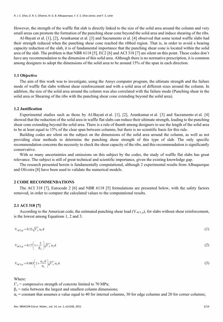
d = section effective depth; u1 = control perimeter according to ACI 318 [7] (Figure 1).
For waffle slabs, the American code recommends that the ribs should have a minimum width (bw) of 100 mm, a maximum height (hb) of 3.5 times the minimum width of the rib and a maximum spacing between the faces of the ribs (s) of 750 mm. The thickness of the topping slab (hf) must be at least 37.5 mm and at most s/12 ratio (Figure 1). For ribs without shear reinforcement, ACI 318 [7] allows the shear strength to be estimated by Equation 4.
ACI,s c w1V f ' b d6
= (4)
Where, f’c = compressive strength of concrete limited to 70 MPa; bw = rib width considered; d = rib effective depth.
Figure 1. Rib geometry and control perimeter according to ACI 318 [7]
2.2 Eurocode 2 [6] According to the European code, the estimated punching shear load (VEC, p) for slabs without shear reinforcement
is given by Equation 5.
( )13EC,p l ck 1V 0.18 100 f u d= ξ ρ (5)
Where, fck = compressive strength of concrete in MPa; ρl = longitudinal reinforcement rate, not greater than 0.02;
( ) 1 200 / d 2.0 ξ = + ≤ ;
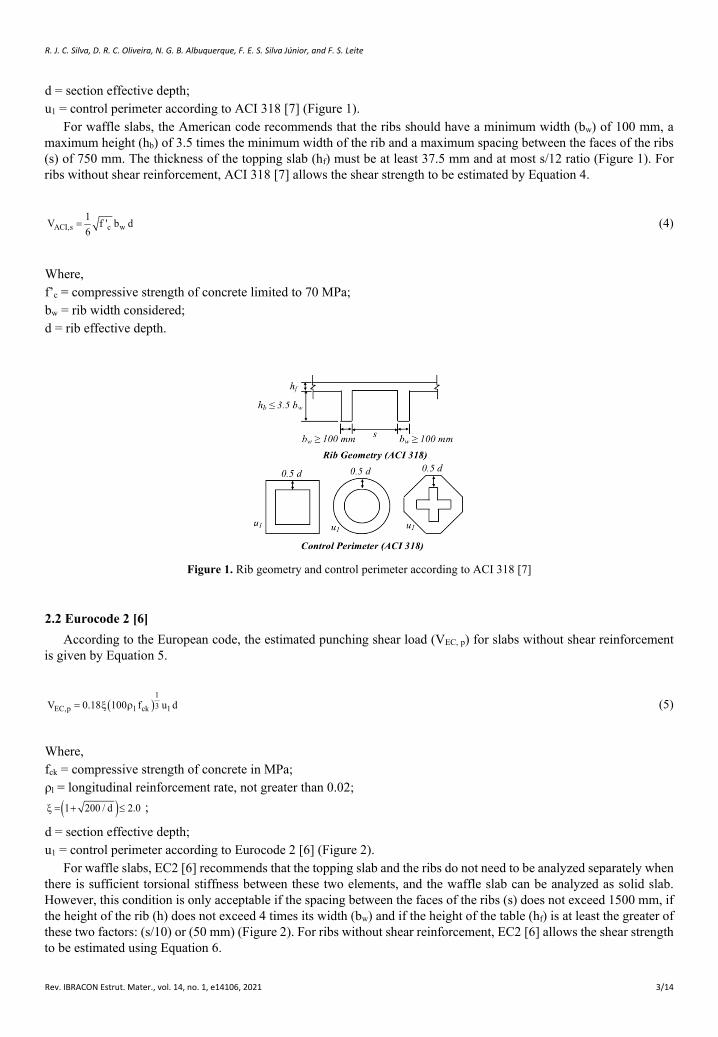
d = section effective depth; u1 = control perimeter according to Eurocode 2 [6] (Figure 2).
For waffle slabs, EC2 [6] recommends that the topping slab and the ribs do not need to be analyzed separately when there is sufficient torsional stiffness between these two elements, and the waffle slab can be analyzed as solid slab. However, this condition is only acceptable if the spacing between the faces of the ribs (s) does not exceed 1500 mm, if the height of the rib (h) does not exceed 4 times its width (bw) and if the height of the table (hf) is at least the greater of these two factors: (s/10) or (50 mm) (Figure 2). For ribs without shear reinforcement, EC2 [6] allows the shear strength to be estimated using Equation 6.
R. J. C. Silva, D. R. C. Oliveira, N. G. B. Albuquerque, F. E. S. Silva Júnior, and F. S. Leite
Rev. IBRACON Estrut. Mater., vol. 14, no. 1, e14106, 2021 4/14
( )13EC, s l ck wV 0.18 100 f b d= ξ ρ (6)
With, ρl = longitudinal reinforcement rate, not greater than 0.02; fck = compressive strength of concrete in MPa; bw = rib width considered; d = rib effective depth.
Figure 2. Rib geometry and control perimeter according to Eurocode 2 [6]
2.3 NBR 6118 [5] According to the Brazilian code, the estimated punching shear load (VNBR, p), for slabs without shear reinforcement,
is given by Equation 7.
( )13NBR,p l ck 1V 0.18 100 f u d= ξ ρ (7)
Where: fck = compressive strength of concrete in MPa; ρl = longitudinal reinforcement rate;
( ) 1 200 / d ξ = + ;
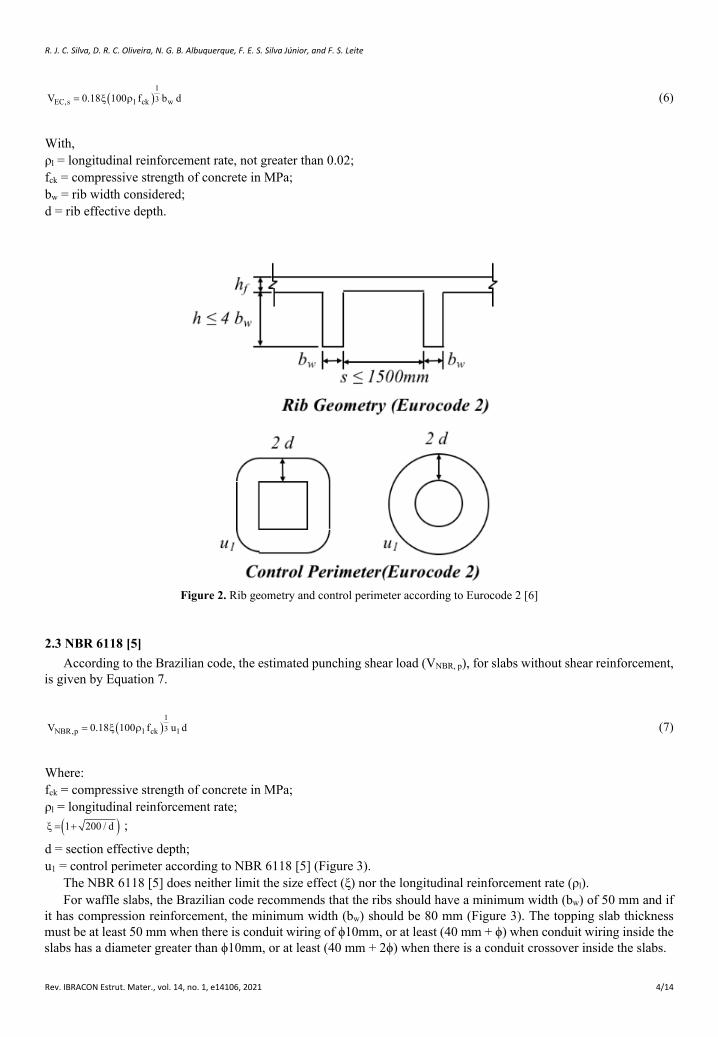
d = section effective depth; u1 = control perimeter according to NBR 6118 [5] (Figure 3).
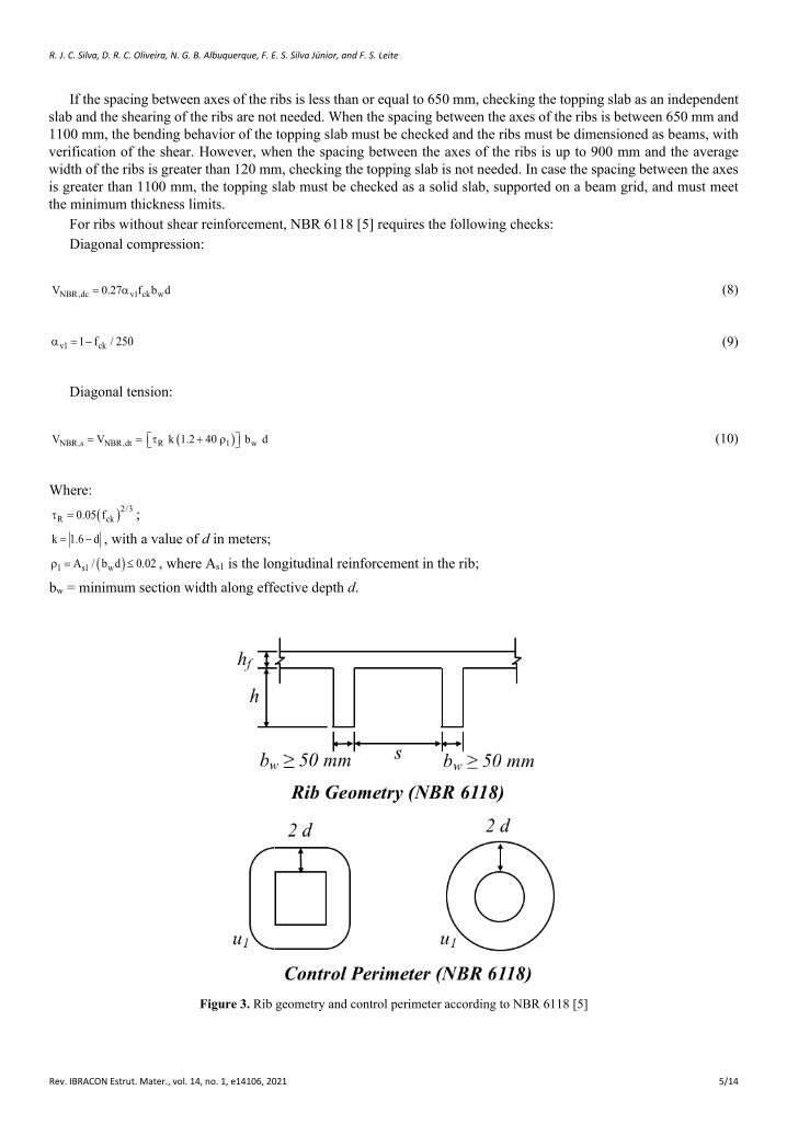
The NBR 6118 [5] does neither limit the size effect (ξ) nor the longitudinal reinforcement rate (ρl). For waffle slabs, the Brazilian code recommends that the ribs should have a minimum width (bw) of 50 mm and if
it has compression reinforcement, the minimum width (bw) should be 80 mm (Figure 3). The topping slab thickness must be at least 50 mm when there is conduit wiring of ϕ10mm, or at least (40 mm + ϕ) when conduit wiring inside the slabs has a diameter greater than ϕ10mm, or at least (40 mm + 2ϕ) when there is a conduit crossover inside the slabs.
R. J. C. Silva, D. R. C. Oliveira, N. G. B. Albuquerque, F. E. S. Silva Júnior, and F. S. Leite
Rev. IBRACON Estrut. Mater., vol. 14, no. 1, e14106, 2021 5/14
If the spacing between axes of the ribs is less than or equal to 650 mm, checking the topping slab as an independent slab and the shearing of the ribs are not needed. When the spacing between the axes of the ribs is between 650 mm and 1100 mm, the bending behavior of the topping slab must be checked and the ribs must be dimensioned as beams, with verification of the shear. However, when the spacing between the axes of the ribs is up to 900 mm and the average width of the ribs is greater than 120 mm, checking the topping slab is not needed. In case the spacing between the axes is greater than 1100 mm, the topping slab must be checked as a solid slab, supported on a beam grid, and must meet the minimum thickness limits.
For ribs without shear reinforcement, NBR 6118 [5] requires the following checks: Diagonal compression:
NBR,dc v1 ck wV 0.27 f b d= α (8)
v1 ck1 f / 250α = − (9)
Diagonal tension:
( )NBR,s NBR,dt R 1 wV V k 1.2 40 b d= = τ + ρ (10)
Where:
( )2/3R ck0.05 fτ = ;
k 1.6 d= − , with a value of d in meters;
( )1 s1 wA / b d 0.02ρ = ≤ , where As1 is the longitudinal reinforcement in the rib; bw = minimum section width along effective depth d.
Figure 3. Rib geometry and control perimeter according to NBR 6118 [5]
R. J. C. Silva, D. R. C. Oliveira, N. G. B. Albuquerque, F. E. S. Silva Júnior, and F. S. Leite
Rev. IBRACON Estrut. Mater., vol. 14, no. 1, e14106, 2021 6/14
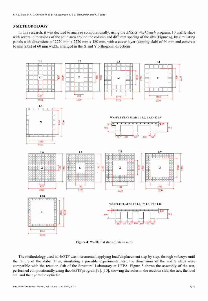
3 METHODOLOGY In this research, it was decided to analyze computationally, using the ANSYS Workbench program, 10 waffle slabs
with several dimensions of the solid area around the column and different spacing of the ribs (Figure 4), by simulating panels with dimensions of 2220 mm x 2220 mm x 180 mm, with a cover layer (topping slab) of 60 mm and concrete beams (ribs) of 60 mm width, arranged in the X and Y orthogonal directions.
Figure 4. Waffle flat slabs (units in mm)
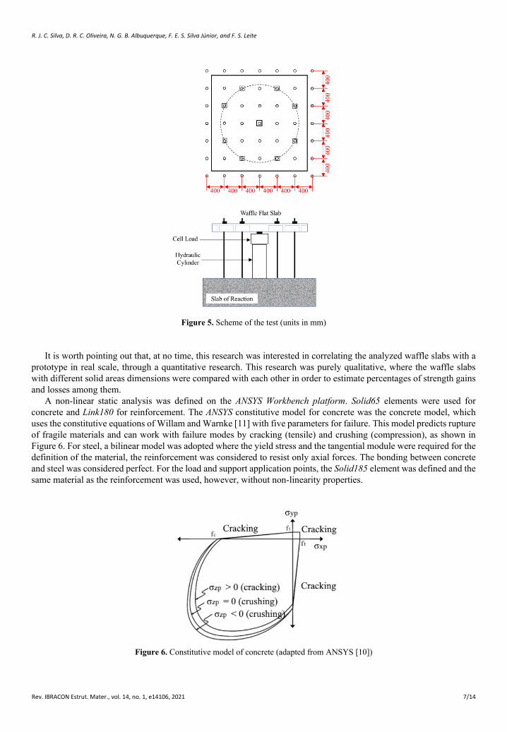
The methodology used in ANSYS was incremental, applying load/displacement step by step, through substeps until the failure of the slabs. Thus, simulating a possible experimental test, the dimensions of the waffle slabs were compatible with the reaction slab of the Structural Laboratory at UFPA. Figure 5 shows the assembly of the test, performed computationally using the ANSYS program [9], [10], showing the holes in the reaction slab, the ties, the load cell and the hydraulic cylinder.
R. J. C. Silva, D. R. C. Oliveira, N. G. B. Albuquerque, F. E. S. Silva Júnior, and F. S. Leite
Rev. IBRACON Estrut. Mater., vol. 14, no. 1, e14106, 2021 7/14
Figure 5. Scheme of the test (units in mm)
It is worth pointing out that, at no time, this research was interested in correlating the analyzed waffle slabs with a prototype in real scale, through a quantitative research. This research was purely qualitative, where the waffle slabs with different solid areas dimensions were compared with each other in order to estimate percentages of strength gains and losses among them.
A non-linear static analysis was defined on the ANSYS Workbench platform. Solid65 elements were used for concrete and Link180 for reinforcement. The ANSYS constitutive model for concrete was the concrete model, which uses the constitutive equations of Willam and Warnke [11] with five parameters for failure. This model predicts rupture of fragile materials and can work with failure modes by cracking (tensile) and crushing (compression), as shown in Figure 6. For steel, a bilinear model was adopted where the yield stress and the tangential module were required for the definition of the material, the reinforcement was considered to resist only axial forces. The bonding between concrete and steel was considered perfect. For the load and support application points, the Solid185 element was defined and the same material as the reinforcement was used, however, without non-linearity properties.
Figure 6. Constitutive model of concrete (adapted from ANSYS [10])
R. J. C. Silva, D. R. C. Oliveira, N. G. B. Albuquerque, F. E. S. Silva Júnior, and F. S. Leite
Rev. IBRACON Estrut. Mater., vol. 14, no. 1, e14106, 2021 8/14
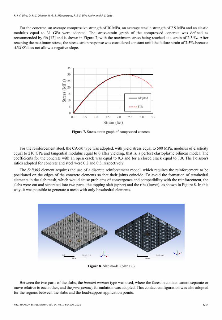
For the concrete, an average compressive strength of 30 MPa, an average tensile strength of 2.9 MPa and an elastic modulus equal to 31 GPa were adopted. The stress-strain graph of the compressed concrete was defined as recommended by fib [12] and is shown in Figure 7, with the maximum stress being reached at a strain of 2.3 ‰. After reaching the maximum stress, the stress-strain response was considered constant until the failure strain of 3.5‰ because ANSYS does not allow a negative slope.
Figure 7. Stress-strain graph of compressed concrete
For the reinforcement steel, the CA-50 type was adopted, with yield stress equal to 500 MPa, modulus of elasticity equal to 210 GPa and tangential modulus equal to 0 after yielding, that is, a perfect elastoplastic bilinear model. The coefficients for the concrete with an open crack was equal to 0.3 and for a closed crack equal to 1.0. The Poisson's ratios adopted for concrete and steel were 0.2 and 0.3, respectively.
The Solid65 element requires the use of a discrete reinforcement model, which requires the reinforcement to be positioned on the edges of the concrete elements so that their joints coincide. To avoid the formation of tetrahedral elements in the slab mesh, which would cause problems of convergence and compatibility with the reinforcement, the slabs were cut and separated into two parts: the topping slab (upper) and the ribs (lower), as shown in Figure 8. In this way, it was possible to generate a mesh with only hexahedral elements.
Figure 8. Slab model (Slab L6)
Between the two parts of the slabs, the bonded contact type was used, where the faces in contact cannot separate or move relative to each other, and the pure penalty formulation was adopted. This contact configuration was also adopted for the regions between the slabs and the load/support application points.
R. J. C. Silva, D. R. C. Oliveira, N. G. B. Albuquerque, F. E. S. Silva Júnior, and F. S. Leite
Rev. IBRACON Estrut. Mater., vol. 14, no. 1, e14106, 2021 9/14
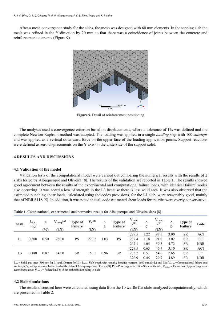
After a mesh convergence study for the slabs, the mesh was designed with 60 mm elements. In the topping slab the mesh was refined in the Y direction by 20 mm so that there was a coincidence of joints between the concrete and reinforcement elements (Figure 9).
Figure 9. Detail of reinforcement positioning
The analyses used a convergence criterion based on displacements, where a tolerance of 1% was defined and the complete Newton-Raphson method was adopted. The loading was applied in a single loading step with 100 substeps and was applied as a vertical downward force on the upper face of the loading application points. Support reactions were defined as zero displacements on the Y axis on the underside of the support solid.
4 RESULTS AND DISCUSSIONS
4.1 Validation of the model Validation tests of the computational model were carried out comparing the numerical results with the results of 2
slabs tested by Albuquerque and Oliveira [8]. The results of the validation are reported in Table 1. The results showed good agreement between the results of the experimental and computational failure loads, with identical failure modes also occurring. It was noted a loss of strength in the L3 because there is less solid area. It was also observed that the estimated punching shear loads, calculated using the codes provisions, for the L1 slab, were reasonably good, mainly that of NBR 6118 [5]. In addition, it was noted that all code estimated shear loads for the ribs were overly conservative.
Table 1. Computational, experimental and normative results for Albuquerque and Oliveira slabs [8]
Slab SA
NM
LL
ρ Vcomp(A) Type of Failure
Vu(B) AB
Type of Failure
Vcode,
p(C) AC
Vcode,
s(D) AD
Type of Failure Code
(%) (kN) (kN) (kN) (kN)
L1 0.500 0.50 280.0 PS 270.5 1.03 PS 229.5 1.22 93.5 3.00 SR ACI 237.4 1.18 91.0 3.02 SR EC 267.1 1.05 59.3 4.72 SR NBR
L3 0.188 0.87 145.0 SR 150.5 0.96 SR 229.5 0.63 46.7 3.10 SR ACI 285.2 0.51 54.6 2.65 SR EC 320.9 0.45 29.7 4.89 SR NBR
LSA = Solid area span (800 mm for L1 and 300 mm for L3); LNM = Slab length with negative bending moment (1600 mm for L1 and L3); Vcomp = Computational failure load via Ansys; Vu = Experimental failure load of the slabs of Albuquerque and Oliveira [8]; PS = Punching shear; SR = Shear in the ribs; Vcode, p = Failure load by punching shear according to code; Vcode, s = Failure load by shear in the ribs according to code.
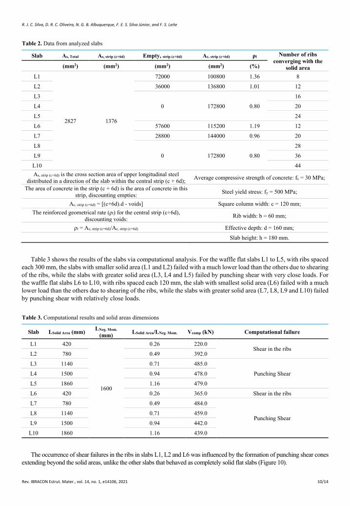
4.2 Slab simulations The results discussed here were calculated using data from the 10 waffle flat slabs analyzed computationally, which
are presented in Table 2.
R. J. C. Silva, D. R. C. Oliveira, N. G. B. Albuquerque, F. E. S. Silva Júnior, and F. S. Leite
Rev. IBRACON Estrut. Mater., vol. 14, no. 1, e14106, 2021 10/14
Table 2. Data from analyzed slabs
Slab As, Total As, strip (c+6d) Empty, strip (c+6d) Ac, strip (c+6d) ρl Number of ribs converging with the
solid area (mm2) (mm2) (mm2) (mm2) (%) L1
2827 1376
72000 100800 1.36 8 L2 36000 136800 1.01 12 L3
0 172800 0.80 16
L4 20 L5 24 L6 57600 115200 1.19 12 L7 28800 144000 0.96 20 L8
0 172800 0.80 28
L9 36 L10 44 As, strip (c+6d) is the cross section area of upper longitudinal steel
distributed in a direction of the slab within the central strip (c + 6d); Average compressive strength of concrete: fc = 30 MPa;
The area of concrete in the strip (c + 6d) is the area of concrete in this strip, discounting empties: Steel yield stress: fy = 500 MPa;
Ac, strip (c+6d) = [(c+6d).d - voids] Square column width: c = 120 mm; The reinforced geometrical rate (ρl) for the central strip (c+6d),
discounting voids: Rib width: b = 60 mm;
ρl = As, strip (c+6d)/Ac, strip (c+6d) Effective depth: d = 160 mm; Slab height: h = 180 mm.
Table 3 shows the results of the slabs via computational analysis. For the waffle flat slabs L1 to L5, with ribs spaced each 300 mm, the slabs with smaller solid area (L1 and L2) failed with a much lower load than the others due to shearing of the ribs, while the slabs with greater solid area (L3, L4 and L5) failed by punching shear with very close loads. For the waffle flat slabs L6 to L10, with ribs spaced each 120 mm, the slab with smallest solid area (L6) failed with a much lower load than the others due to shearing of the ribs, while the slabs with greater solid area (L7, L8, L9 and L10) failed by punching shear with relatively close loads.
Table 3. Computational results and solid areas dimensions
Slab LSolid Area (mm) LNeg. Mom. (mm) LSolid Area/LNeg. Mom. Vcomp (kN) Computational failure
L1 420
1600
0.26 220.0 Shear in the ribs
L2 780 0.49 392.0 L3 1140 0.71 485.0
Punching Shear L4 1500 0.94 478.0 L5 1860 1.16 479.0 L6 420 0.26 365.0 Shear in the ribs L7 780 0.49 484.0
Punching Shear L8 1140 0.71 459.0 L9 1500 0.94 442.0 L10 1860 1.16 439.0
The occurrence of shear failures in the ribs in slabs L1, L2 and L6 was influenced by the formation of punching shear cones extending beyond the solid areas, unlike the other slabs that behaved as completely solid flat slabs (Figure 10).

R. J. C. Silva, D. R. C. Oliveira, N. G. B. Albuquerque, F. E. S. Silva Júnior, and F. S. Leite
Rev. IBRACON Estrut. Mater., vol. 14, no. 1, e14106, 2021 11/14
Figure 10. Cracks forming the punching shear cone in waffle flat slab with smaller solid area and larger solid area
The shear on the ribs (Figure 11) for slabs L1, L2 and L6 show critical shear stresses (maximum and minimum) in the ribs, which caused failure by diagonal tension in the ribs with loads below the punching shear failure loads estimated by the design codes. The reduction in strength of slabs L1, L2 and L6 would not occur if the solid areas were larger.
Figure 11. Shear stresses in the ribs of the slabs L1, L2 e L6
R. J. C. Silva, D. R. C. Oliveira, N. G. B. Albuquerque, F. E. S. Silva Júnior, and F. S. Leite
Rev. IBRACON Estrut. Mater., vol. 14, no. 1, e14106, 2021 12/14
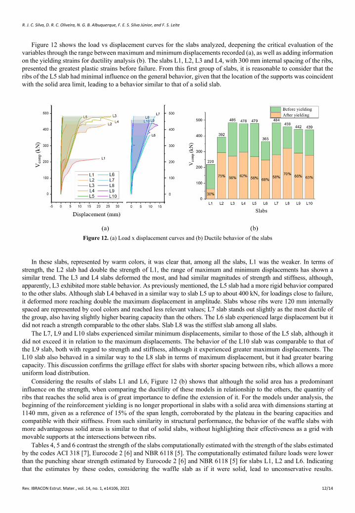
Figure 12 shows the load vs displacement curves for the slabs analyzed, deepening the critical evaluation of the variables through the range between maximum and minimum displacements recorded (a), as well as adding information on the yielding strains for ductility analysis (b). The slabs L1, L2, L3 and L4, with 300 mm internal spacing of the ribs, presented the greatest plastic strains before failure. From this first group of slabs, it is reasonable to consider that the ribs of the L5 slab had minimal influence on the general behavior, given that the location of the supports was coincident with the solid area limit, leading to a behavior similar to that of a solid slab.
Figure 12. (a) Load x displacement curves and (b) Ductile behavior of the slabs
In these slabs, represented by warm colors, it was clear that, among all the slabs, L1 was the weaker. In terms of strength, the L2 slab had double the strength of L1, the range of maximum and minimum displacements has shown a similar trend. The L3 and L4 slabs deformed the most, and had similar magnitudes of strength and stiffness, although, apparently, L3 exhibited more stable behavior. As previously mentioned, the L5 slab had a more rigid behavior compared to the other slabs. Although slab L4 behaved in a similar way to slab L5 up to about 400 kN, for loadings close to failure, it deformed more reaching double the maximum displacement in amplitude. Slabs whose ribs were 120 mm internally spaced are represented by cool colors and reached less relevant values; L7 slab stands out slightly as the most ductile of the group, also having slightly higher bearing capacity than the others. The L6 slab experienced large displacement but it did not reach a strength comparable to the other slabs. Slab L8 was the stiffest slab among all slabs.
The L7, L9 and L10 slabs experienced similar minimum displacements, similar to those of the L5 slab, although it did not exceed it in relation to the maximum displacements. The behavior of the L10 slab was comparable to that of the L9 slab, both with regard to strength and stiffness, although it experienced greater maximum displacements. The L10 slab also behaved in a similar way to the L8 slab in terms of maximum displacement, but it had greater bearing capacity. This discussion confirms the grillage effect for slabs with shorter spacing between ribs, which allows a more uniform load distribution.
Considering the results of slabs L1 and L6, Figure 12 (b) shows that although the solid area has a predominant influence on the strength, when comparing the ductility of these models in relationship to the others, the quantity of ribs that reaches the solid area is of great importance to define the extension of it. For the models under analysis, the beginning of the reinforcement yielding is no longer proportional in slabs with a solid area with dimensions starting at 1140 mm, given as a reference of 15% of the span length, corroborated by the plateau in the bearing capacities and compatible with their stiffness. From such similarity in structural performance, the behavior of the waffle slabs with more advantageous solid areas is similar to that of solid slabs, without highlighting their effectiveness as a grid with movable supports at the intersections between ribs.
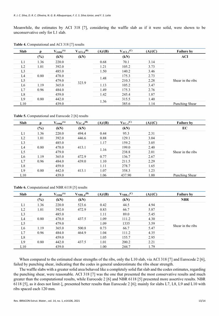
Tables 4, 5 and 6 contrast the strength of the slabs computationally estimated with the strength of the slabs estimated by the codes ACI 318 [7], Eurocode 2 [6] and NBR 6118 [5]. The computationally estimated failure loads were lower than the punching shear strength estimated by Eurocode 2 [6] and NBR 6118 [5] for slabs L1, L2 and L6. Indicating that the estimates by these codes, considering the waffle slab as if it were solid, lead to unconservative results.
R. J. C. Silva, D. R. C. Oliveira, N. G. B. Albuquerque, F. E. S. Silva Júnior, and F. S. Leite
Rev. IBRACON Estrut. Mater., vol. 14, no. 1, e14106, 2021 13/14
Meanwhile, the estimates by ACI 318 [7], considering the waffle slab as if it were solid, were shown to be unconservative only for L1 slab.
Table 4. Computational and ACI 318 [7] results
Slab ρ Vcomp(A) VACI, p(B) (A)/(B) VACI, s(C) (A)/(C) Failure by (%) (kN) (kN) (kN) ACI
L1 1.36 220.0
323.9
0.68 70.1 3.14
Shear in the ribs
L2 1.01 392.0 1.21 105.2 3.73 L3
0.80 485.0 1.50 140.2 3.46
L4 478.0 1.48 175.3 2.73 L5 479.0 210.3 2.28 L6 1.19 365.0 1.13 105.2 3.47 L7 0.96 484.0 1.49 175.3 2.76 L8
0.80 459.0 1.42 245.4 1.87
L9 442.0 1.36 315.5 1.40 L10 439.0 385.6 1.14 Punching Shear
Table 5. Computational and Eurocode 2 [6] results
Slab ρ Vcomp(A) VEC, p(B) (A)/(B) VEC, s(C) (A)/(C) Failure by (%) (kN) (kN) (kN) EC
L1 1.36 220.0 494.4 0.44 95.3 2.31
Shear in the ribs
L2 1.01 392.0 446.6 0.88 129.1 3.04 L3
0.80 485.0
413.1 1.17 159.2 3.05
L4 478.0 1.16 199.0 2.40 L5 479.0 238.8 2.01 L6 1.19 365.0 472.9 0.77 136.7 2.67 L7 0.96 484.0 439.0 1.10 211.5 2.29 L8
0.80 459.0
413.1 1.11 278.7 1.65
L9 442.0 1.07 358.3 1.23 L10 439.0 1.06 437.90 1.00 Punching Shear
Table 6. Computational and NBR 6118 [5] results
Slab ρ Vcomp(A) VNBR, p(B) (A)/(B) VNBR, s(C) (A)/(C) Failure by (%) (kN) (kN) (kN) NBR
L1 1.36 220.0 523.6 0.42 44.5 4.94
Shear in the ribs
L2 1.01 392.0 472.9 0.83 66.7 5.87 L3
0.80 485.0
437.5 1.11 89.0 5.45
L4 478.0 1.09 111.2 4.30 L5 479.0 1.09 1335 3.59 L6 1.19 365.0 500.8 0.73 66.7 5.47 L7 0.96 484.0 464.9 1.04 111.2 4.35 L8
0.80 459.0
437.5 1.05 155.7 2.95
L9 442.0 1.01 200.2 2.21 L10 439.0 1.00 244.7 1.79
When compared to the estimated shear strengths of the ribs, only the L10 slab, via ACI 318 [7] and Eurocode 2 [6], failed by punching shear, indicating that the codes in general underestimate the ribs shear strength.
The waffle slabs with a greater solid area behaved like a completely solid flat slab and the codes estimates, regarding the punching shear, were reasonable. ACI 318 [7] was the one that presented the most conservative results and much greater than the computational results, while Eurocode 2 [6] and NBR 6118 [5] presented more assertive results. NBR 6118 [5], as it does not limit ξ, presented better results than Eurocode 2 [6]; mainly for slabs L7, L8, L9 and L10 with ribs spaced each 120 mm.
R. J. C. Silva, D. R. C. Oliveira, N. G. B. Albuquerque, F. E. S. Silva Júnior, and F. S. Leite
Rev. IBRACON Estrut. Mater., vol. 14, no. 1, e14106, 2021 14/14
The rule of thumb, to consider 15% of the span to define the length of the solid area in the waffle flat slab would be equivalent to 71% of the negative bending moment of the analyzed slabs. Following this rule, the minimum size of 1136 mm (0.71⋅1600 mm = 1136 mm) would be indicated for the solid area of the analyzed waffle flat slabs. Thus, the slabs L3, L4, L5, L8, L9 and L10 would be conforming to this minimum value. In this way, the waffle flat slabs that conforming to this minimum size of solid area showed good results, compatible with the solid flat slab.
The finite element simulation allowed to clarify the effect of the parameters of variation of the solid area around a central column of waffle flat slabs, through the investigation of the change in failure mode. This discussion sought to warn that the use of punching shear formulations for solid flat slabs in waffle flat slabs can be extremely dangerous.
5 CONCLUSIONS The conclusions of this work are limited only to the results of the 10 slabs analyzed here. Further analyses,
computational and experimental, are necessary to validate these results. Thus, it can be concluded that:
• Waffle flat slabs with small solid areas had reduced strength compared to waffle flat slabs with larger solid areas; • Waffle flat slabs with the largest solid areas behaved like solid flat slabs; • Punching shear cones on waffle flat slabs with small solid areas exceeded these areas, causing shear failures by
diagonal tension in the ribs of the slabs. • Regarding the computational results, NBR 6118 [5] best estimated the punching shear results, while the ACI [7]
had the worst estimation, being quite conservative. • Still in relation to computational results, ACI [7], Eurocode 2 [6] and NBR 6118 [5] underestimate the shear
strengths of the ribs of the waffle flat slabs. • The practical rule for determining the solid area dimensions corresponding to 15% of the span length showed good
results compared to the computational results.
6 ACKNOWLEDGMENTS The authors would like to thank the Federal University of Pará (UFPA), the State University Vale do Acaraú (UVA)
and the Federal University of Rio Grande (FURG) for the interaction for the development of this research.
7 REFERENCES [1] A. F. Al-Bayati, L. T. Leong, and L. A. Clark, "Concentric punching shear of waffle slab," ACI Struct. J., vol. 112, no. 5, pp. 533–
542, Aug 2015.
[2] A. F. Al-Bayati, T. L. Lau, and L. A. Clark, "Eccentric punching shear of waffle slab," ACI Struct. J., vol. 115, no. 1, pp. 163–174, Jan 2018.
[3] C. Arunkumar, K. Saketh, S. S. Senthil, and T. M. Jeyashree, "Behaviour of punching shear in normal RC slab and waffle slab," Asian J. Civ. Eng., vol. 19, no. 1, pp. 27–33, Jan 2018.
[4] P. V. P. Sacramento, M. S. Picanço, and D. R. C. Oliveira, "“Lajes nervuradas de concreto armado com viga-faixa”, RIEM -," Rev. IBRACON Estrut. Mater., vol. 11, no. 5, pp. 981–996, Oct 2018. http://dx.doi.org/10.1590/s1983-41952018000500005.
[5] Associação Brasileira de Normas Técnicas, Design of Concrete Structures – Procedure, NBR 6118, 2014.
[6] European Committee for Standardization, Design of Concrete Structures, Part 1, General Codes and Codes for Buildings, Eurocode 2, 2010.
[7] American Concrete Institute, Building Code Requirements for Structural Concrete and Commentary, ACI 318M-19, 2019.
[8] N. G. B. Albuquerque and D. R. C. Oliveira, “Análise experimental de lajes lisas nervuradas de concreto armado com região maciça de geometria variável,” in An. 51º Congr. Bras. Concr., Oct., 2009, pp. 1-17.
[9] ANSYS Inc., ANSYS Composite PrepPost User’s Guide, Release 15.0, 2013.
[10] ANSYS Inc., ANSYS Mechanical APDL Material Reference, Release 15.0, 2013.
[11] K. J. Willam and E. P. Warnke, “Constitutive model for the triaxial behaviour of concrete”, in Proc. Int. Assoc. Bridge Struct. Eng., May, 1974, pp. 1-30.
[12] Fédération Internationale du Béton, fib Model Code for Concrete Structures 2010, Model Code 2010, 2012.
Author contributions: RJCS: conceptualization, writing, methodology; DRCO: supervision; FESSJ: software; NGBA and FSL: formal analysis.
Editors: Fernando Fonseca, José Luiz Antunes de Oliveira e Sousa, Guilherme Aris Parsekian.