Organizations, Codes & Standards
39
Chapter 2 – Organizations, Codes & Standards SDR Workbook – 2012 IBC Version 1-22 Steven T. Hiner, MS, SE While PBSD has yet to be fully developed, it is expected to be used in future building codes to provide a methodology to more reliably predict seismic risk in all buildings in terms more useful to building owners and building users. Under the ASCE 7-10 seismic design provisions, there exist implied performance levels as demonstrated by Figure 2.1. For example, Risk Category II (i.e., I e = 1.0) structures designed to ASCE 7-10 provisions are expected to meet the following performance levels: Collapse prevention for MCE R ground motions Life-safety for Design ground motions (i.e., 2/3 MCE R ) Immediate occupancy for Frequent ground motions (i.e. , ~ 50% in 50 years / 100 year return interval) Risk Category IV (i.e., I e = 1.5) structures designed to ASCE 7-10 provisions are expected to meet the following performance levels: Life-safety for MCE R ground motions Immediate occupancy for Design ground motions (i.e., 2/3 MCE R ) Operational for Frequent ground motions Similarly, Risk Category III (i.e., I e = 1.25) structures designed to ASCE 7-10 provisions are expected to meet performance levels that fall between the Risk Category IV and Risk Category II structures as shown in Figure 2.1 below. Figure 2.1 – Risk Category vs. Ground Motion (Ref. 12 - Figure C11.5-1)
description
Organizations
Transcript of Organizations, Codes & Standards

Chapter 2 – Organizations, Codes & Standards SDR Workbook – 2012 IBC Version
1-22 Steven T. Hiner, MS, SE
While PBSD has yet to be fully developed, it is expected to be used in future building codes to provide a methodology to more reliably predict seismic risk in all buildings in terms more useful to building owners and building users.
Under the ASCE 7-10 seismic design provisions, there exist implied performance levels as demonstrated by Figure 2.1. For example, Risk Category II (i.e., Ie = 1.0) structures designed to ASCE 7-10 provisions are expected to meet the following performance levels:
Collapse prevention for MCER ground motions
Life-safety for Design ground motions (i.e., 2/3 MCER)
Immediate occupancy for Frequent ground motions (i.e. , ~ 50% in 50 years / 100 year return interval)
Risk Category IV (i.e., Ie = 1.5) structures designed to ASCE 7-10 provisions are expected to meet the following performance levels:
Life-safety for MCER ground motions
Immediate occupancy for Design ground motions (i.e., 2/3 MCER)
Operational for Frequent ground motions
Similarly, Risk Category III (i.e., Ie = 1.25) structures designed to ASCE 7-10 provisions are expected to meet performance levels that fall between the Risk Category IV and Risk Category II structures as shown in Figure 2.1 below.
Figure 2.1 – Risk Category vs. Ground Motion (Ref. 12 - Figure C11.5-1)
Owner
Highlight
Owner
Highlight
Owner
Text Box
4-10-14

SDR Workbook – 2012 IBC Version Chapter 3 – General Provisions & Seismic Design Criteria
Steven T. Hiner, MS, SE 1-31
Site Class Adjusted MCER Acceleration Parameters IBC §1613.3.3 SMS & SM1 represent the site class adjusted MCER spectral response acceleration parameters at short periods and at 1-second period respectively, and are determined by the following equations:
SMS = Fa SS IBC (16-37)
SM1 = Fv S1 IBC (16-38)
where:
Fa = Site coefficient per IBC Table 1613.3.3(1)
Fv = Site coefficient per IBC Table 1613.3.3(2)
Site coefficient Fa is function of the Site Class and the short period mapped spectral response acceleration parameter (SS). Site coefficient Fv is a function of the Site Class and the 1-second period mapped spectral response acceleration parameter (S1).
Fa & Fv are based on the results of empirical analyses of strong-motion data and analytical studies of site response. In general, softer soils exhibit greater amplification of earthquake ground motions than stiffer soils, and that amplification can be even more significant for longer period (e.g., taller) structures than for shorter period structures (e.g., Fv values are greater than Fa values for Site Class C, D & E).
Design Spectral Response Acceleration Parameters IBC §1613.3.4 SDS & SD1 represent the 5% damped design spectral response acceleration parameters at short periods and at 1-second period respectively and they are determined by the following equations:
SDS = 2/3 SMS IBC (16-39)
SD1 = 2/3 SM1 IBC (16-40)
NOTE: Table 3.2 (p. 1-33) and Table 3.3 (p. 1-34) are provided as short cut procedures in determining SDS & SD1 respectively when SS, S1 & Site Class are known (Site Class D may be assumed unless given).
Figure 3.1 – Design Response Spectrum (Ref. 9 - ASCE 7 – Figure 11.4-1)
where:
TL = per ASCE 7 – Figure 22-12
DS
DS S
ST 1
STT 2.00
Steven Hiner
Highlight

Chapter 3 – General Provisions & Seismic Design Criteria SDR Workbook – 2012 IBC Version
1-36 Steven T. Hiner, MS, SE
Alternative Seismic Design Category Determination IBC §1613.3.5.1
Where S1 < 0.75, the Seismic Design Category is permitted to be determined from IBC Table 1613.3.5(1) alone (i.e, using SDS only) when all of the following apply:
Ta < 0.8 TS in each of the two orthogonal directions, and
the fundamental period of the structure used to calculate the story drift - T < TS … in each of the two orthogonal directions, and
ASCE 7 (12.8-2) is used to determine the seismic response coefficient … )( e
DSS IR
SC , and
The diaphragms are rigid (per ASCE 7 – §12.3.1) or for diaphragms that are flexible, the distance between vertical elements of the seismic force-resisting system (SFRS) ≤ 40 feet
Simplified Design Procedure IBC §1613.3.5.2
Where the alternate Simplified Design Procedure of ASCE 7 – §12.14 is used, the Seismic Design Category shall be determined in accordance with ASCE 7.
3.7 ASCE 7 Seismic Design Criteria ASCE 7 – Chapter 11
Scope ASCE 7 - §11.1.2 Every structure (e.g., buildings and nonbuilding structures), and portion thereof, including nonstructural components, shall be designed and constructed to resist the effects of earthquake motions as prescribed by the seismic requirements of ASCE 7.
Applicability ASCE 7 - §11.1.3 Structures and their nonstructural components shall be designed and constructed in accordance with the requirements of the following chapters based on the type of structure or component:
Buildings: ASCE 7 – Chapter 12
Nonbuilding Structures: ASCE 7 – Chapter 15
Nonstructural Components: ASCE 7 – Chapter 13
Seismically Isolated Structures: ASCE 7 – Chapter 17
Structures with Damping Systems: ASCE 7 – Chapter 18
Seismic Importance Factor, Ie ASCE 7 - §11.5.1 Each structure shall be assigned an importance factor (Ie) in accordance with ASCE 7 – Table 1.5-2 … based on the Risk Category of the building (or other structure) from IBC – Table 1604.5.
Risk Category I I = 1.0 Risk Category II I = 1.0 Risk Category III (high occupancy) I = 1.25* Risk Category IV (essential facilities) I = 1.5*
The seismic importance factor (Ie) is used in the Seismic Response Coefficient (CS) equations with the intent to raise the yield level for important structures (e.g., hospitals, fire stations, emergency operation centers, hazardous facilities, etc.).
Use of an importance factor greater than one is intended to provide for a lower inelastic demand on a structure which should result in lower levels of structural and nonstructural damage.
Steven Hiner
Highlight

Chapter 4 – Seismic Design Requirements for Building Structures SDR Workbook – 2012 IBC Version
1-54 Steven T. Hiner, MS, SE
4.9 Equivalent Lateral Force Procedure ASCE 7 – §12.8 Seismic Base Shear, V Strength Design force leveli ASCE 7 – §12.8.1
The seismic base shear in a given direction shall be determined in accordance with the following:
WCV S ASCE 7 (12.8-1)
Figure 4.12 – Seismic Base Shear
Seismic Response Coefficient, CS ASCE 7 – §12.8.1.1
The seismic response coefficient (CS) shall be determined as follows:
)( e
DSS IR
SC ASCE 7 (12.8-2)
NOTE: ASCE 7 (12.8-2) will always governs when T ≤ TS … which typically occurs with low rise and/or short period structures (i.e., 3 stories).
CS need not exceed the following:
)(
1
e
DS IRT
SC for T ≤ TL ASCE 7 (12.8-3)
NOTE: ASCE 7 (12.8-3) typically governs for longer period structures when TS ≤ T ≤ TL … but CS minimum per ASCE 7 (12.8-5) and (12.8-6) need to be considered.
)(2
1
e
LDS IRT
TSC for T > TL ASCE 7 (12.8-4)
NOTE: ASCE 7 (12.8-4) can apply for very long period (i.e., very tall) structures, when T > TL … but CS minimum per ASCE 7 (12.8-5) and (12.8-6) will typically govern over ASCE 7 (12.8-4).
Owner
Highlight
Owner
Highlight
Owner
Highlight
Owner
Highlight

SDR Workbook – 2012 IBC Version Chapter 5 – Earthquake Loads and Load Combinations
Steven T. Hiner, MS, SE 1-75
T = self-straining load (e.g., arising from contraction or expansion resulting from temperature change, shrinkage, moisture change, creep in component materials, movement due to differential settlement or combinations thereof)
W = load due to wind pressure
Strength Design or Load & Resistance Factor Design IBC §1605.2 All applicable Strength Design (SD or LRFD) load combinations must be considered since the most critical load effect may occur when one or more of the contributing loads (e.g., D, E, L, Lr, S ) are not acting.
Basic (SD or LRFD) Load Combinations IBC §1605.2.1
Where Strength Design (or Load and Resistance Factor Design) is used, structures and portions thereof shall be designed to resist the most critical effects resulting from the equations of IBC §1605.2.1.
There are a total of seven SD/LRFD basic load combinations equations in the IBC. Only the two load combinations which include the earthquake load (E) are noted below:
1.2(D + F) + 1.0E + f1L + 1.6H + f2S IBC (16-5)
or … (1.2 + 0.2SDS)D + QE + f1L + f2S … when F = 0 & H = 0
0.9(D + F) + 1.0E + 1.6H IBC (16-7)
or … (0.9 – 0.2SDS)D – QE … when F = 0 & H = 0
Exception: Where other factored load combinations are specifically required by the provisions of the IBC (i.e., Chapter 19 – Concrete) … such combinations shall take precedence.
Allowable Stress Design IBC §1605.3 All applicable Allowable Stress Design (ASD) load combinations must be considered since the most critical load effect may occur when one or more of the contributing loads (e.g., D, E, L, Lr, S ) are not acting.
Basic (ASD) Load Combinations IBC §1605.3.1
Where Allowable Stress Design (or Working Stress Design) … is used, structures and portions thereof shall be designed to resist the most critical effects resulting from the equations of IBC §1605.3.1.
There are a total of nine Basic (ASD) Load Combination equations in the IBC. Only the three load combinations which include the earthquake load (E) are noted below:
D + H + F + (0.6W or 0.7E) IBC (16-12)
or … (1.0 + 0.14SDS)D + 0.7 QE … when F = 0 & H = 0
D + H + F + 0.75(0.7E) + 0.75L + 0.75S IBC (16-14)
or … (1.0 + 0.105SDS)D + 0.75(0.7 QE) + 0.75L + 0.75S
0.6(D + F) + 0.7E + H IBC (16-16)
or … (0.6 – 0.14SDS)D – 0.7 QE … when F = 0 & H = 0
Exceptions: see IBC §1605.3.1 for exceptions to crane hook loads, to flat roof snow loads ≤ 30 psf, roof live loads ≤ 30 psf, flat roof snow loads > 30 psf, etc.
Owner
Highlight
Owner
Highlight

Chapter 5 – Earthquake Loads and Load Combinations SDR Workbook – 2012 IBC Version
1-78 Steven T. Hiner, MS, SE
5.3 Equivalent Lateral Force Procedure Overview
I, II, III or IV Risk Category
Ie Seismic Importance Factor
Ss & S1 Mapped MCER spectral response acceleration parameters
A, B, C, D*, E or F Site Class
Fa & Fv Site Coefficients
SMS & SM1 Soil modified MCER spectral response acceleration parameters
SDS & SD1 Design spectral response acceleration parameters
A*, B*, C, D, E or F Seismic Design Category
Ta Approximate Fundamental Period
CS Seismic Response Coefficient
V = CSW Seismic Base Shear at Strength Level (i.e. SD/LRFD)
Fx Vertical Distribution of Seismic Force
Owner
Highlight
Owner
Highlight

SDR Workbook – 2012 IBC Version Chapter 6 – Seismic Design Requirements for Nonstructural Components
Steven T. Hiner, MS, SE 1-81
Chapter 6 Seismic Design Requirements for Nonstructural Components
6.1 ASCE 7 – Chapter 13 Overview
Scope ASCE 7 – §13.1.1 ASCE 7 – Chapter 13 establishes minimum design criteria for nonstructural components that are permanently attached to structures, and for their supports and attachments.
A nonstructural component is a part or element of an architectural, electrical or mechanical system.
Seismic Design Category ASCE 7 – §13.1.2 Nonstructural components shall be assigned to the same Seismic Design Category (SDC) as the structure that they occupy, or to which they are attached.
Component Importance Factor, Ip ASCE 7 – §13.1.3 All components shall be assigned a component importance factor (Ip), which will be equal to 1.5 or 1.0. Use an Ip = 1.5 if any of the following conditions apply:
1. The component is required to function for life-safety purposes after an earthquake, including fire protection sprinkler systems and egress stairways
2. The component conveys, supports, or otherwise contains toxic, highly toxic, or explosive substances …
3. The component is in (or attached to) a Risk Category IV structure (i.e., essential facility), and it is needed for continued operation of the facility or its failure could impair the continued operation of the facility
4. The component conveys, supports, or otherwise contains hazardous substances …
All other components shall be assigned an Ip = 1.0
Exemptions ASCE 7 – §13.1.4 The following nonstructural components are exempt from the requirements of ASCE 7 – Chapter 13:
1. Furniture (except storage cabinets > 5 feet tall)
2. Temporary or movable equipment
3. Architectural components in SDC = B (other than parapets supported by bearing walls or shear walls) provided Ip = 1.0
4. Mechanical and electrical components in SDC = B
5. Mechanical and electrical components in SDC = C provided that Ip = 1.0
6. Mechanical and electrical components in SDC = D, E, or F where Ip = 1.0, the component is positively attached to the structure, flexible connections are provided between component and associated ductwork, piping, and conduit and either:
Component weighs ≤ 400 lbs and has a C.M. located ≤ 4 feet above the adjacent floor level; or
Owner
Highlight
SDR Workbook – 2012 IBC Version Chapter 6 – Seismic Design Requirements for Nonstructural Components
Steven T. Hiner, MS, SE 1-87
Specific Requirements & References
Table 6.2 – Specific Mechanical & Electrical Component References
Item Section Reference
Mechanical Components ASCE 7 – §13.6.3 Electrical Components ASCE 7 – §13.6.4 Component Supports ASCE 7 – §13.6.5 Utility and Service Lines ASCE 7 – §13.6.6 HVAC Ductwork ASCE 7 – §13.6.7 Piping Systems ASCE 7 – §13.6.8 Boilers and Pressure Vessels ASCE 7 – §13.6.9 Elevator & Escalator Design Requirements ASCE 7 – §13.6.10 Other Mechanical & Electrical Components ASCE 7 – §13.6.11
6.6 Structural Walls and their Anchorage ASCE 7 – §12.11
Design for Out-of-Plane Forces ASCE 7 – §12.11.1 Structural walls and their anchorage shall be designed for a force normal to the surface (e.g., out-of-plane) equal to:
weDSp WISF 4.0
wW10.0 minimum
Figure 6.2 – Out-of-Plane Forces on Structural Walls
Wall with Cantilever Parapet Wall without Parapet
Steven Hiner
Highlight
Steven Hiner
Highlight

Chapter 6 – Seismic Design Requirements for Nonstructural Components SDR Workbook – 2012 IBC Version
1-88 Steven T. Hiner, MS, SE
Anchorage of Structural Walls and Transfer of Design Forces into Diaphragms ASCE 7 – §12.11.2 Wall Anchorage Forces, Fp ASCE 7 – §12.11.2.1
The anchorage of structural walls to supporting construction (e.g., roof or floor diaphragms) shall provide a direct connection capable of resisting the following:
peaDSp WIKSF 4.0 ASCE 7 (12.11-1)
pea WIK2.0 minimum
where:
100
0.1 fa
LK ≤ 2.0 maximum ASCE 7 (12.11-2)
Fp = the design force in the individual anchors
SDS = short period design spectral response acceleration parameter
Ie = seismic importance factor
Lf = flexible diaphragm span (feet), use 0 for rigid diaphragms
Wp = the weight of the masonry or concrete wall tributary to the anchor = Wwall (hw / 2 + hp) (anchor spacing) … for (one-story) walls with a parapet = Wwall (hw / 2) (anchor spacing) … for (one-story) walls without a parapet
Where the anchorage is not located at the roof and all diaphragms are not flexible, the value from ASCE 7 (12.11-1) is permitted to be multiplied by (1 + 2z/h) / 3, where z is the height of the anchor above the base of the structure and h is the height of the roof above the base (e.g., h = hn).
NOTE: Structural walls shall be designed to resist bending between anchors where anchor spacing exceeds 4 feet (i.e., purlin anchors > 4’-0” o.c.).
Refer to Figure 6.3 below for examples of the Lf and Ka values that would be appropriate to determine the wall anchorage force for the structural walls on each wall line depicted for Building A & Building B.
Figure 6.3 – Wall Anchorage Examples
a. Building A b. Building B
Steven Hiner
Highlight
Steven Hiner
Highlight
Steven Hiner
Highlight

SDR Workbook – 2012 IBC Version Chapter 6 – Seismic Design Requirements for Nonstructural Components
Steven T. Hiner, MS, SE 1-89
The following values of Lf and Ka would apply for structural wall anchorage for Building A shown in Figure 6.3a (Building A) -
As Flexible Diaphragm:
Wall anchorage for line A & B: Lf = 150 feet → Ka = 2.0 maximum
Wall anchorage for line 1 & 2: Lf = 80 feet → Ka = 1.8 As Rigid Diaphragm:
Wall anchorage for ALL lines: Lf = 0 feet → Ka = 1.0 The following values of Lf and Ka would apply for structural wall anchorage for Building B shown in Figure 6.3b (Building B) -
As Flexible Diaphragm:
Wall anchorage for line A & B (line 1 to 2): Lf = 100 feet → Ka = 2.0
Wall anchorage for line A & B (line 2 to 3): Lf = 50 feet → Ka = 1.5
Wall anchorage for line 1, 2 & 3: Lf = 80 feet → Ka = 1.8 As Rigid Diaphragm:
Wall anchorage for ALL lines: Lf = 0 feet → Ka = 1.0
Additional Requirements for SDC = C, D, E, or F ASCE 7 – §12.11.2.2
Diaphragms for structures assigned to SDC = C, D, E, or F shall meet the following additional requirements:
1. Transfer of Anchorage Forces -
Diaphragms shall be provided with continuous ties (or struts) between diaphragm chords to distribute these anchorage forces into the diaphragm(s)
Diaphragm connections shall be positive, mechanical, or welded
Added chords are permitted to be used to form subdiaphragms (see p. 1-150) to transmit the anchorage forces to the main continuous cross-ties
The maximum length-to-width ratio of the structural subdiaphragm shall be 2.5 to 1
Connections and anchorages capable of resisting the prescribed forces shall be provided between the diaphragm and the attached components
Connections shall extend into the diaphragm a sufficient distance to develop the force transferred into the diaphragm
2. Steel Elements - the strength design forces for steel elements (i.e., purlin anchors), with the exception of anchor bolts and reinforcing steel, shall be increased by 1.4 times the forces otherwise required by ASCE 7 – §12.11 (i.e., use 1.4 Fp anchorage force for strap purlin anchors)
3. Wood Diaphragms - The continuous ties or struts shall be in addition to the diaphragm sheathing
Anchorage shall not be accomplished by use of toe nails or nails subject to withdrawal
Wood ledgers or framing shall not be used in cross-grain bending or cross-grain tension
4. Metal Deck Diaphragms - metal deck shall not be used as the continuous ties (or struts) … required by ASCE 7 – §12.11.2.2 in the direction perpendicular to the deck span.
Steven Hiner
Highlight
Steven Hiner
Highlight
Steven Hiner
Highlight

SDR Workbook – 2012 IBC Version Chapter 7 – Seismic Design Requirements for Nonbuilding Structures
Steven T. Hiner, MS, SE 1-101
Determination of Seismic Factors - R, 0 & Cd
R, 0 & Cd are to be determined from ASCE 7 – Table 15.4-2 for nonbuilding structures NOT similar to buildings.
In general, R & 0 values assigned to these nonbuilding structures are less than those assigned to building structures (and nonbuilding structures similar to buildings). This is because buildings tend to have structural redundancy due to multiple bays and frame lines and contain nonstructural and non-considered resisting elements that effectively give buildings greater damping, strength and ductility during an earthquake.
Seismic Base Shear, V Strength Design force level ASCE 7 – §12.8.1 When the fundamental period is greater than or equal to 0.06 second (i.e., T ≥ 0.06 second), the
seismic base shear in a given direction shall be determined in accordance with the following:
WCV S ASCE 7 (12.8-1)
Seismic Response Coefficient, CS ASCE 7 – §12.8.1.1
The Seismic Response Coefficient (CS) shall be determined as follows:
)( e
DSS IR
SC ASCE 7 (12.8-2)
NOTE: ASCE 7 (12.8-2) typically governs for nonbuilding structures, when T < TS
CS need not exceed the following:
)(
1
IRT
SC D
S for T ≤ TL ASCE 7 (12.8-3)
and …
)(2
1
e
LDS IRT
TSC for T > TL ASCE 7 (12.8-4)
CS shall not be less than:
03.0044.0 eDSS ISC minimum ASCE 7 (15.4-1)
(see ASCE 7-05 Supplement No. 2)
In addition, for nonbuilding structures where S1 ≥ 0.6 … CS shall not be less than:
)(
8.0 1
eS IR
SC * minimum ASCE 7 (15.4-2)
*NOTE: See ASCE 7 – 15.4.1, item 2 for an exception for Tanks and Vessels.
Steven Hiner
Line

Chapter 8 – Diaphragm Design & Wall Rigidity SDR Workbook – 2012 IBC Version
1-108 Steven T. Hiner, MS, SE
8.2 Diaphragm Types
Diaphragm Flexibility ASCE 7 – §12.3.1
The structural analysis shall consider the relative stiffnesses of diaphragms (floor and/or roof), and the vertical elements of the seismic force-resisting system (e.g., shear walls, braced frames, moment frames).
Unless a diaphragm can be idealized as either flexible or rigid … the structural analysis shall explicitly include consideration of the stiffness of the diaphragm (i.e., semi-rigid modeling assumption).
Flexible Diaphragm Condition ASCE 7 – §12.3.1.1
Diaphragms constructed of untopped steel decking (i.e., metal deck without concrete fill) or wood structural panels (WSP) are permitted to be idealized as flexible if any of the following conditions exist:
Structures where the vertical elements are steel braced frames; steel and concrete composite braced frames; or concrete, masonry, steel, or steel and concrete composite shear walls
One- and two-family dwellings
Structures of light-frame construction (i.e., wood studs or metal studs) where all of the following conditions are met:
1. Topping of concrete or similar materials is not placed over wood structural panel (WSP) diaphragms except for nonstructural toppings 1½ inches thick
2. Each line of vertical elements of the seismic force-resisting system (SFRS) complies with the allowable story drift of ASCE 7 Table 12.12-1
Rigid Diaphragm Condition ASCE 7 – §12.3.1.2
Diaphragms of concrete slabs (or concrete filled metal deck) with span-to-depth ratios of 3 to 1 or less (i.e., L/d ≤ 3) in structures having no horizontal irregularities are permitted to be idealized as rigid.
Calculated Flexible Diaphragm Condition ASCE 7 – §12.3.1.3
Diaphragms not satisfying the conditions to be considered flexible or rigid … are permitted to be idealized as flexible where the computed maximum in-plane deflection of the diaphragm (under lateral load) is more than two times the average story drift of adjoining vertical elements of the seismic-force-resisting system of the associated story under equivalent tributary lateral load (see Figure 8.4).
Figure 8.4 – Calculated Flexible Diaphragm Condition
2
2 minmaxmax
Diaphragm Deflection ASCE 7 – §12.12.2
The deflection of the diaphragm … shall not exceed the permissible deflection of the attached elements (e.g., bearing walls) … which shall be that deflection that will permit the attached element to maintain its structural integrity under the individual loading and continue to support the prescribed loads.
Steven Hiner
Highlight
Steven Hiner
Highlight

SDR Workbook – 2012 IBC Version Chapter 8 – Diaphragm Design & Wall Rigidity
Steven T. Hiner, MS, SE 1-111
Figure 8.8 below demonstrates the comparison that is often made between the analysis of a uniformly loaded flexible diaphragm (on the left) and a uniformly loaded simply supported beam (on the right). For the design of flexible diaphragms, the shear diagram can be used to determine the maximum unit shear at the end supports (e.g., shear walls). The moment diagram can be used to determine the maximum chord force, or the chord force at a specific point on the chord boundary member (see Figure 8.10, p. 1-113).
Figure 8.8 – Flexible Diaphragm Loading (Ref. 19)
Owner
Highlight

SDR Workbook – 2012 IBC Version Chapter 8 – Diaphragm Design & Wall Rigidity
Steven T. Hiner, MS, SE 1-115
The Drag Force should always be equal to zero at each end of the collector. Numerical rounding of the calculated unit diaphragm shear and unit wall shear may result in Drag Forces that do not quite “zero” at the ends of the collector.
Typically, the wall top plates (at the diaphragm boundary) are used as the chords and collectors for wood framed stud wall construction.
Collector Elements ASCE 7 – §12.10.2 Collector elements shall be provided that are capable of transferring the seismic forces originating in other portions of the structure to the element providing resistance to those forces (e.g., shear walls, braced frames, moment resisting frames, etc.).
Seismic Design Category C, D, E or F ASCE 7 – §12.10.2.1
In structures assigned to SDC = C, D, E or F - collector elements and their connections including connections to vertical elements (e.g., shear walls, braced frames, moment resisting frames, etc.) shall be designed to resist the maximum of the forces determined from ASCE 7 – §12.10.2.1 items 1, 2 and 3 (see p. 1-77), which considers the seismic load effects including overstrength factor (0) of ASCE 7 – §12.4.3.
ASCE 7 – §12.10.2.1 allows two exceptions: (drag) forces calculated from Fpx maximum per ASCE 7 equation (12.10-3) using ASCE 7 – §12.4.2.3 load combinations; and for structures braced entirely by light-frame shear walls (i.e., wood studs or cold formed steel studs) … with drag forces determined from the governing Fpx force per ASCE 7 (12.10-1), (12.10-2) and (12.10-3).
8.6 Masonry & Concrete Wall Rigidity
Cantilever Shear Wall – Deflection
Figure 8.12 – Cantilever Shear Wall / Pier
ShearFlexureTotal
GA
HF
EI
HFC
2.1
3
3
where: F = force at top of wall H = height of wall to force, F E = modulus of elasticity G = shear modulus A = area = t D I = moment of inertia = t D3/12
Wall Rigidity, R Rigidity is proportional to the reciprocal of deflection, and is essentially the relative stiffness of the lateral resisting element (i.e., shear wall).
Masonry & concrete shear walls resist lateral loads in proportion to their Rigidities (R), therefore only "relative rigidities" are needed.
The relative cantilever wall rigidities are determined for each shear wall using their respective H/D ratios and Table D1 - Relative Rigidity of Cantilever Shear Walls / Piers (Appendix D, p. 5-20).
Owner
Highlight
Owner
Highlight
Owner
Highlight

Chapter 8 – Diaphragm Design & Wall Rigidity SDR Workbook – 2012 IBC Version
1-116 Steven T. Hiner, MS, SE
Figure 8.13 – Cantilever Shear Wall Relative Rigidity
21
11 RR
RFV
21
22 RR
RFV
Fixed Shear Wall – Deflection
Figure 8.14 – Fixed Shear Wall / Pier
ShearFlexureTotal
GA
HF
EI
HFF
2.1
12
3
where: F = force at top of wall H = height of wall to force, F E = modulus of elasticity G = shear modulus A = area = t D I = moment of inertia = t D3/12
Shear Wall with Openings This method can be used to approximate the shear force in a particular pier when the lateral force (F ) to the total wall is known, such as for a flexible diaphragm building. The assumption is that the lighter shaded portion of wall above and below the openings will provide fixity of the darker shaded individual piers. Determine the "Fixed" Rigidity (RF) of each of the individual piers using their respective H/D ratios and Table D2 - Relative Rigidity of Fixed Shear Walls / Piers (Appendix D, p. 5-21).
Figure 8.15 – Shear Wall with Fixed Piers
Force to Pier 1,
4321
11
FFFF
F
RRRR
RFF
Owner
Highlight

SDR Workbook – 2012 IBC Version Chapter 9 – IBC Chapter 23 – Wood
Steven T. Hiner, MS, SE 1-139
where:
vh EEE
The weight of the wall (WW) can be considered a dead load effect (D). While the weight of the wall might be considered in the determination of the total seismic force on the shear wall (i.e., V1 + CSWW), it will not be used to determine Ev because the dead load effect (D) does not contribute to the determination of the calculated unit wall shear.
NOTE: The Redundancy factor () shall be considered in the design of the shear walls.
Therefore, E = 1VQE Eh …
So the ASD calculated unit wall shear:
ASD wall )7.0(
widthshear wall
shear) walll(0.7)(tota 1
b
V (units of plf)
NOTE: The equation above is used to determine the drag force, and may be used for shear wall design when the wall weight (Ww) is not significant, not given in a problem statement, or when the diaphragm design force (e.g., ws = fpx = Fpx / L) includes all perimeter walls of the building … essentially when the base shear (V ) is used to design the diaphragm.
Otherwise, the weight of the shear wall (Ww) can be included in the ASD calculated unit wall shear:
ASD calculated wall ))(7.0( 1
b
WCV WS (units of plf)
Using the ASD calculated wall and SDPWS Table 4.3A (see Table 9.5), choose the appropriate:
WSP panel grade
WSP nominal panel thickness
Fastener (nail) size
Fastener (nail) spacing
Such that the ASD allowable wall ≥ ASD calculated wall
Unit Wall Shear Reduction SDPWS Table 4.3.4, footnote 1 The nominal unit shear capacities of SDPWS Table 4.3A will require a reduction for walls resisting seismic loads for any individual shear wall aspect ratio that exceeds 2:1 (but is less than 3.5:1) –
h/b ≤ 2:1 → use nominal unit shear capacities from SDPWS Table 4.3A 3 with no reduction
2:1 < h/b ≤ 3.5:1 → use nominal unit shear capacities from SDPWS Table 4.3A 3 multiplied by 2b/h
NOTE: For h/b = 3.5:1 … this will result in 2b/h = 0.57, or a 43% reduction in the nominal unit shear capacities noted in SDPWS Table 4.3A when resisting seismic loads (not wind loads).
For 2:1 < h/b ≤ 3½:1 … the reduction factor 2b/h will be somewhere between 1.00 and 0.57, resulting in a 0% to 43% reduction in the nominal unit wall shear values noted in SDPWS Table 4.3A when resisting seismic loads (not wind loads).
Owner
Cross-Out
Owner
Cross-Out
Owner
Highlight
Owner
Highlight

SDR Workbook – 2012 IBC Version Chapter 10 – Other Material Chapters
Steven T. Hiner, MS, SE 1-165
NOTE: Following the January 17, 1994 Northridge Earthquake, over 100 steel buildings with welded moment-resisting frames were found to have beam-to-column connection fractures. Usually the fractures initiated at the complete joint penetration weld between the beam bottom flange and the column flange. Investigators have suggested that the fractures may be due to a number of factors such as notch effects created by a left in place weld backing bar; sub-standard welding (excessive porosity, slag inclusions, incomplete fusion); and/or pre-earthquake fractures due to initial shrinkage of the weld during cool-down.
In September 1994, the International Conference of Building Officials (ICBO) adopted an emergency code change to the 1994 Uniform Building Code (UBC). This code change omitted the pre-qualified connection (see Figure 10.7) and required that connections be designed to sustain inelastic rotation and develop the strength criteria as demonstrated by cyclic testing or calculation.
In November 2000, the SAC Joint Venture finalized the welded steel moment frame issues which were published by the Federal Emergency Management Agency (FEMA) in the following documents:
FEMA 350 – Recommended Seismic Design Criteria for New Steel Moment-Frame Buildings
FEMA 351 – Recommended Seismic Evaluation and Upgrade Criteria for Existing Welded Steel Moment-Frame Buildings
FEMA 352 – Recommended Post-Earthquake Evaluation and Repair Criteria for Welded Steel Moment-Frame Buildings
FEMA 353 – Recommended Specifications and Quality Assurance Guidelines for Steel Moment-Frame Construction for Seismic Applications
Doubler Plates Doubler plates are sometimes added to one (or both sides) of the column web and are intended to increase the columns web shear strength and web crippling capacity within the panel zone.
Continuity Plates Continuity plates are sometimes added to provide “continuity” of the intersecting beam (or girder) flanges across the column web. The requirement for continuity plates is a function of the column yield strength, flange width, and flange thickness, and the intersecting beam yield strength, flange width, and flange thickness.
Intermediate Moment Frames (IMF) AISC 341-10 – §E.2 R = 4½ for steel IMF*
IMF’s are expected to withstand limited inelastic deformations (in their members and connections) when subjected to the Design Basis Earthquake ground motions.
Limited special detailing of beam-column joint, therefore limited ductility (i.e., lower R).
Ordinary Moment Frames (OMF) AISC 341-10 – §E.1 R = 3½ for steel OMF*
OMF’s are expected to withstand minimal inelastic deformations (in their members and connections) when subjected to the Design Basis Earthquake ground motions.
Very limited special detailing of beam-column joint, therefore very limited ductility (i.e., very low R).
*NOTE: Typically steel IMF’s and OMF’s will not be permitted in structures assigned to Seismic Design Category D, E or F … with the exception of steel OMF’s meeting the requirements of ASCE 7 – §12.2.5.6.1 for SDC = D or E or §12.2.5.6.2 for SDC = F, and steel IMF’s meeting requirements of ASCE 7 – §12.2.5.7.1 for SDC = D or §12.2.5.7.2 for SDC = E or §12.2.5.7.3 for SDC = F.
Owner
Highlight

SDR Workbook – 2012 IBC Version Part 2 – Example Problems
Steven T. Hiner, MS, SE 2-7
SM1 = Fv S1 IBC (16-38) = 1.3 (0.52) = 0.68
SD1 = 2/3 SM1 IBC (16-40) = 2/3 (0.68) = 0.45i
NOTE: Alternatively, SDS & SD1 can be quickly determined using Tables 3.2 & 3.3 (p. 1-33 & 34):
Table 3.2 (p. 1-33) SS = 1.25 Site Class C SDS = 0.83
Table 3.3 (p. 1-34) S1 = 0.52 Site Class C SD1 = 0.45
B.) Seismic Design Category, SDC
S1 = 0.52 < 0.75 therefore, use IBC Table 1613.3.5(1) & Table 1613.3.5(2) to determine SDC
SDS = 0.83 & RC = II 2012 IBC Table 1613.3.5(1) SDC = D
SD1 = 0.45 & RC = II 2012 IBC Table 1613.3.5(2) SDC = D
iSDC = Dii
C.) Approximate Fundamental Period, Ta
xnta hCT ASCE 7 (12.8-7)
Steel SCBF ASCE 7 – Table 12.8-2: all other structural systems – Ct = 0.02 & x = 0.75
Ta = 0.02 (hn)0.75
= 0.02 (36 feet)0.75 = 0.29 secondi
Or using Table C1 (Appendix C, p. 5-18) CBF & hn = 36 feet Ta = 0.29 second
NOTE: T = 0.29 second < 83.0
45.01 DS
DS S
ST = 0.54 second ASCE (12.8-2) will govern Cs
D.) Seismic Response Coefficient, CS
)( e
DSS IR
SC =
)0.16(
)83.0( = 0.138 governs ASCE 7 (12.8-2)
CS need not exceed the following,
)(
1
e
DS IRT
SC =
)0.16(29.0
)45.0( = 0.259 ASCE 7 (12.8-3)
NOTE: ASCE 7 (12.8-4), (12.8-5), and (12.8-6) are not applicable since T < TS (and T << TL)
CS = 0.138i
E.) Seismic Base Shear, V V = CS W ASCE 7 (12.8-1)
= 0.138 (280 kips) = 38.6 kipsi
Steven Hiner
Highlight

SDR Workbook – 2012 IBC Version Part 2 – Example Problems
Steven T. Hiner, MS, SE 2-9
SD1 = 2/3 SM1 IBC (16-40) = 2/3 (0.28) = 0.19i
Table 3.2 (p. 1-33) SS = 0.73 Site Class B SDS = 0.49 … by interpolation
Table 3.3 (p. 1-34) S1 = 0.28 Site Class B SD1 = 0.19
B.) Seismic Design Category, SDC
S1 = 0.28 < 0.75 therefore, use IBC Table 1613.3.5(1) & Table 1613.3.5(2) to determine SDC
SDS = 0.49 & RC = IV 2012 IBC Table 1613.3.5(1) SDC = D
SD1 = 0.19 & RC = IV 2012 IBC Table 1613.3.5(2) SDC = D
iSDC = Dii
C.) Approximate Fundamental Period, Ta
xnta hCT ASCE 7 (12.8-7)
Concrete SMF ASCE 7 – Table 12.8-2: Concrete moment-resisting frames – Ct = 0.016 & x = 0.9
Ta = 0.016 (hn)0.9
= 0.016 (67 feet)0.9 = 0.70 secondi
Using Table C1 (Appendix C, p. 5-18) Concrete MRF & hn = 67 feet Ta = 0.70 second
NOTE: T = 0.70 second > 49.0
19.01 DS
DS S
ST = 0.39 second ASCE 7 (12.8-2) will not govern Cs
D.) Seismic Response Coefficient, CS
)( e
DSS IR
SC =
)5.18(
)49.0( = 0.092 ASCE 7 (12.8-2)
CS need not exceed the following,
)(
1
e
DS IRT
SC =
)5.18(70.0
)19.0( = 0.051 governs ASCE 7 (12.8-3)
CS shall not be less than the following,
eDSS ISC 044.0 = 0.044(0.49)(1.5) = 0.032 ASCE 7 (12.8-5)
≥ 0.01 minimum
NOTE: ASCE 7 (12.8-4) is not applicable since T = 0.70 second << TL = 12 seconds & ASCE 7 (12.8-6) is not applicable since S1 = 0.28 < 0.6
CS = 0.051i
E.) Seismic Base Shear, V V = Cs W ASCE 7 (12.8-1)
= 0.051 (5,000 kips) = 255 kipsi
Steven Hiner
Highlight

SDR Workbook – 2012 IBC Version Part 2 – Example Problems
Steven T. Hiner, MS, SE 2-11
SD1 = 2/3 SM1 IBC (16-40) = 2/3 (1.35) = 0.90i
Table 3.2 (p. 1-33) SS = 1.75 Site Class D (assumed) SDS = 1.17
Table 3.3 (p. 1-34) S1 = 0.90 Site Class D (assumed) SD1 = 0.90
B.) Seismic Design Category, SDC
S1 = 0.90 > 0.75 & RC = II 2012 IBC §1613.3.5 SDC = E
iSDC = Ei
C.) Approximate Fundamental Period, Ta
xnta hCT ASCE 7 (12.8-7)
WSP shear wall ASCE 7 – Table 12.8-2: all other structural systems – Ct = 0.02 & x = 0.75
Ta = 0.02 (hn)0.75
= 0.02 (25 feet)0.75 = 0.22 secondi
Using Table C1 (Appendix C, p. 5-18) Shear Walls & hn = 25 feet Ta = 0.22 second
NOTE: T = 0.22 second < 17.1
90.01 DS
DS S
ST = 0.77 second ASCE 7 (12.8-2) will govern Cs.
D.) Seismic Response Coefficient, CS
)( e
DSS IR
SC =
)0.15.6(
)17.1( = 0.180 governs ASCE 7 (12.8-2)
CS need not exceed the following,
)(
1
e
DS IRT
SC =
)0.15.6(22.0
)90.0( = 0.629 ASCE 7 (12.8-3)
NOTE: ASCE 7 (12.8-4), (12.8-5), and (12.8-6) are not applicable since T < TS (and T << TL)
CS = 0.180i
E.) Seismic Base Shear, V V = CS W ASCE 7 (12.8-1)
= 0.180 (135 kips) = 24.3 kipsi
NOTE: For low-rise buildings (i.e., ≤ 3 stories), ASCE 7 (12.8-2) will typically govern since these
structures have relatively short periods such that T < TS … therefore, it is typically not necessary to calculate the structures period from equation ASCE 7 (12.8-7), or seismic response coefficient from ASCE 7 (12.8-3), (12.8-4), (12.8-5) & (12.8-6) for low-rise buildings.
Steven Hiner
Highlight

SDR Workbook – 2012 IBC Version Part 2 – Example Problems
Steven T. Hiner, MS, SE 2-13
Table 3.2 (p. 1-33) SS = 1.52 Site Class E SDS = 0.91 … by interpolation
Table 3.3 (p. 1-34) S1 = 0.76 Site Class E SD1 = 1.22 … by interpolation
B.) Seismic Design Category, SDC
S1 = 0.76 > 0.75 & RC = IV 2012 IBC §1613.3.5 SDC = F
iSDC = Fi
C.) Approximate Fundamental Period, Ta
xnta hCT ASCE 7 (12.8-7)
Dual System D.1 - steel EBF & steel SMF ASCE 7 – Table 12.8-2: Ct = 0.03 & x = 0.75
Ta = 0.03 (hn)0.75
= 0.03 (108 feet)0.75 = 1.01 secondi
Using Table C1 (Appendix C, p. 5-18) Dual System D.1 & hn = 108 feet Ta = 1.01 second
NOTE: T = 1.00 second < 91.0
22.11 DS
DS S
ST = 1.34 second ASCE 7 (12.8-2) will govern Cs
D.) Seismic Response Coefficient, CS
)( e
DSS IR
SC =
)5.18(
)91.0( = 0.170 governs ASCE 7 (12.8-2)
CS need not exceed the following,
)(
1
e
DS IRT
SC =
)5.18(00.1
)22.1( = 0.229 ASCE 7 (12.8-3)
NOTE: ASCE 7 (12.8-4), (12.8-5), and (12.8-6) are not applicable since T < TS (and T << TL)
CS = 0.170i
E.) Seismic Base Shear, V V = CS W ASCE 7 (12.8-1)
= 0.170 (24,000 kips) = 4,080 kipsi
NOTE: This scenario is somewhat unusual in that ASCE 7 (12.8-2) ended up as the governing equation for the seismic response coefficient (CS) even though the building was an 8-story structure … simply because T = Ta < TS. The reason that ASCE 7 (12.8-3) did not end up governing is because the structure is supported by soft soil (Site Class E). The presence of soft soil will “push” TS toward the longer period range of the design response spectrum to where taller/longer period structures will still be governed by ASCE 7 (12.8-2).
Steven Hiner
Highlight

SDR Workbook – 2012 IBC Version Part 2 – Example Problems
Steven T. Hiner, MS, SE 2-33
B.) N-S DIRECTION: Diaphragm span = L1 = L2 = L / 2 = 62.5′, d = 50′
1. Maximum Unit (Roof) Diaphragm Shear, r The addition of the interior shear wall on line 2 will create two diaphragms that span equal amounts (e.g., L1 = L2 = L / 2). One diaphragm spans from line 1 to line 2, and the other diaphragm spans from line 2 to line 3.
ws = V / L = (35,000 lbs) / 125′ = 280 plf
V1 = V3 = ws (L1 / 2) = ws (L2 / 2) = (280 plf )(62.5′) / 2 = 8,750 lbs
roof 1 = 3 = V1 / d = (8,750 lbs) / 50′ = 175 plfi (SD force level)
From Part A.1 - roof 1 = 3 = 350 plf → 50% reduction in max. unit (roof) diaphragm sheari
2. Maximum Unit Wall Shear, w By inspection, the maximum unit wall shear will occur on line 2 & 3 -
Wall Line 1: V1 = V / 4 & total shear wall length, Σb1 = 30′
wall 1 = V1 / Σw = (8,750 lbs) / 30′ = 291 plfi (SD force level)
Wall Line 2: V2 = V / 2 & total shear wall length, Σb2 = 50′
wall 1 = V1 / Σw = (17,500 lbs) / 50′ = 350 plfi ← governs (SD force level)
Wall Line 3: V3 = V / 4 & total shear wall length, Σb3 = 25′
wall 3 = V3 / Σw = (8,750 lbs) / 25′ = 350 plfi ← governs (SD force level)
From Part A.2 - wall 3 = 700 plf → 50% reduction in max. unit wall sheari
3. Maximum Chord Force on lines A & B, CF max. CF = ws (L1)
2 / 8d = (280 plf )(62.5′)2 / 8(50′) = 2,730 lbsi (SD force level)
From Part A.3 - max. chord force CF = 10,940 lbs → 75% reduction in maximum chord forcei
4. Maximum Drag Force, Fd
Drag Force - Line 1 Drag Force - Line 2 Drag Force - Line 3
Owner
Highlight

SDR Workbook – 2012 IBC Version Part 2 – Example Problems
Steven T. Hiner, MS, SE 2-37
4. Drag Force Diagram on lines A & B, Fd
roof A = B = 494 plf
Wall Line A: Fd = 0 lbs
Wall Line B: Fd = (494 plf)(20′) = 9,880 lbs (SD/LRFD force level)
Drag Force – Line A Drag Force – Line B
B.) E-W DIRECTION: L = 40′, d = 70′
1. Design Seismic Force to Diaphragm, ws = fp1 = Fp1/L roof DL + 20% snow exterior walls
ws = fp1 = 0.190 [(16 psf + 20%·100 psf)(70′) + (85 psf)(14′/2 + 2′)(2 walls)] = 770 plfi
2. Unit Roof Shear on lines 1 & 2, r V1 = V2 = ws L / 2 = (770 plf)(40′/2) = 15,400 lbs
Roof 1 = 2 = V1 / d = (15,400 lbs) / 70′ = 220 plfi (SD/LRFD force level)
3. Maximum Chord Force on lines A & B, CF max. M = ws L
2 / 8 = (770 plf)(40′)2 / 8 = 154,000 lb-ft
max. CF = (154,000 lb-ft) / 70’ = 2,200 lbsi (SD/LRFD force level)
4. Shear Force to walls 1A & 1B Relative Rigidities: assume cantilever walls, Table D1 - Relative Rigidity of Cantilever Shear
Walls / Piers (Appendix D, p. 5-20)
Wall 1A: H/D = 14′/11′= 1.27 Table D1 (p. 5-20) R1A = 0.833
Wall 1B: H/D = 14′/22′ = 0.64 Table D1 (p. 5-20) R1B = 3.369
R = R1A + R1B = 0.833 + 3.369 = 4.202
Owner
Highlight
Owner
Highlight
Owner
Highlight
Part 2 – Example Problems SDR Workbook – 2012 IBC Version
2-54 Steven T. Hiner, MS, SE
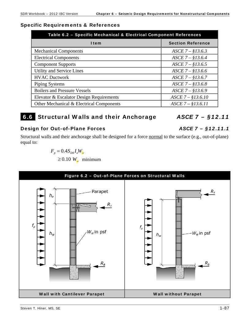
B.) Center of Rigidity, CR
Shear Wall Rigidities: (assume cantilever walls, Table D1 - Relative Rigidity of Cantilever Shear Walls / Piers, Appendix D, p. 5-20)
Wall A : H/D = 15′/30′ = 0.50 Table D1 (p. 5-20) RA = 5.0
Wall B : H/D = 15′/20′ = 0.75 Table D1 (p. 5-20) RB = 2.54
BAY RRR = 5.0 + 2.54 = 7.54
Wall C : H/D = 15′/40′ = 0.375 Table D1 (p. 5-20) RC = 7.49
Wall D : RD = RB = 2.54
Wall E : RE = RD = 2.54
EDCX RRRR = 7.49 + 2.54 + 2.54 = 12.57
Y
YCR
R
xRX = [5.0 (0′) + 2.54 (80′)] / (7.54) = 26.9 feeti
X
XCR
R
yRY = [7.49 (40′) + 2.54 (10′) + 2.54 (0′)] / (12.57) = 25.9 feeti
Owner
Highlight
Owner
Highlight
Owner
Highlight
Owner
Highlight

SDR Workbook – 2012 IBC Version Part 3 – Multiple Choice Problems
Steven T. Hiner, MS, SE 3-19
4.19 What is the approximate fundamental period (Ta) of a 110 foot tall steel eccentrically braced frame (steel EBF) building?
a. 0.68 second b. 1.02 second c. 1.20 second d. 1.54 second
4.20 What is the approximate fundamental period (Ta) of a 5 story building using entirely
intermediate steel moment frames (steel IMF), with all story heights greater than 10 feet?
a. 0.50 second b. 0.43 second c. 0.64 second d. 0.89 second
4.21 What is the approximate fundamental period (Ta) of a 195 foot tall special steel moment frame
(steel SMF) building?
a. 1.04 second b. 1.56 second c. 1.90 second d. 2.12 second
4.22 What is the approximate fundamental period (Ta) of a 35 foot tall Dual System building (w/
steel SMF’s & reinforced concrete shear walls)?
a. 0.48 second b. 0.39 second c. 0.35 second d. 0.29 second
4.23 Given TS = 0.6 second & Seismic Design Category D (SDC = D), which of the following
structures would not be permitted the use of the Equivalent Lateral Force (ELF) procedure?
a. A 200 foot tall regular structure with T = 2.4 seconds b. A 3-story light-frame irregular structure of Risk Category II c. A 150 feet tall structure with T = 2.0 seconds and reentrant corner irregularity d. All of the above e. Both a & c
An owner proposes to construct an office building of Seismic Design Category D using steel special concentrically braced frames (SCBF) as the vertical seismic force-resisting elements (in both principal directions). Answer questions 4.24 to 4.27.
4.24 What response modification coefficient (R) should be used for seismic design?
a. 8 b. 7 c. 6 d. 3¼
Owner
Highlight
Owner
Highlight
Owner
Highlight

Part 3 – Multiple Choice Problems SDR Workbook – 2012 IBC Version
3-34 Steven T. Hiner, MS, SE
5.3 A lateral analysis of a 2-story office building determines that a steel braced frame column has the following axial loads: D = 20 kips, L = 15 kips, Lr = 0 kips and E = 25 kips. Assume = 1.0 to determine the maximum axial compression force in this column using the Strength Design (SD or LRFD) load combinations of IBC §1605.2.
a. 45.0 kips b. 52.9 kips c. 56.5 kips d. 61.2 kips
5.4 In ASCE 7 – §12.4.2.1, the symbol QE represents which of the following?
a. The effects of the horizontal seismic forces from the seismic base shear (V ) b. The effects of the horizontal seismic forces from the nonstructural component seismic
design force (Fp) c. The seismic design base shear (V ) d. Both a & b
5.5 Which of the following conditions would require the use of the load combinations with
overstrength factor (Ω0) of ASCE 7 – §12.4.3.2?
I. Vertical structural irregularity type 4 (ASCE 7 – Table 12.3-2) II. Vertical structural irregularity type 5a (ASCE 7 – Table 12.3-2) III. Horizontal structural irregularity type 4 (ASCE 7 – Table 12.3-1)
a. I b. I & III c. II & III d. I, II & III
5.6 Use of a redundancy factor ( ρ) greater than 1.0 is intended to:
a. reduce the inelastic response and ductility demand of a structure b. increase the seismic base shear (V) on a structure c. decrease the calculated story drift within a structure d. Both a & b
A column of a steel special concentrically braced frame (SCBF), of a single-story Medical Office building (SDC = D), is determined to support the following axial load effects: dead load - D = 35 kips, floor live load - L = 0 kips, roof live load - Lr = 15 kips, and horizontal seismic load effect - QE = 15 kips. Given SDS = 1.25, overstrength factor Ω0 = 2, and redundancy factor = 1.3, answer questions 5.7 through 5.13.
5.7 What is the vertical seismic load effect (Ev) axial force in this column?
a. 0 kips b. ± 7.0 kips c. ± 8.8 kips d. ± 11.7 kips
5.8 What is the horizontal seismic load effect (Eh) axial force in this column?
a. ± 15.0 kips b. ± 19.5 kips c. ± 24.4 kips d. ± 11.7 kips
Owner
Highlight

SDR Workbook – 2012 IBC Version Part 3 – Multiple Choice Problems
Steven T. Hiner, MS, SE 3-35
5.9 What is the maximum axial compression force in this column using the Strength Design (SD or LRFD) load combinations of IBC §1605.2?
a. 53.0 kips b. 61.5 kips c. 66.9 kips d. 70.3 kips
5.10 What is the minimum axial compression force in this column using the Strength Design (SD or
LRFD) load combinations of IBC §1605.2?
a. 3.2 kips b. 7.3 kips c. 9.1 kips d. 11.7 kips
5.11 What is the horizontal seismic load effect with overstrength factor (Emh) axial force in this
column?
a. ± 15.0 kips b. ± 20.0 kips c. ± 30.0 kips d. ± 37.5 kips
5.12 What is the maximum axial compression force in this column using the strength design load
combinations with overstrength factor of ASCE 7 – §12.4.3.2?
a. 50.8 kips b. 63.2 kips c. 72.0 kips d. 80.8 kips
5.13 What is the minimum axial compression force in this column using the strength design load
combinations with overstrength factor of ASCE 7 – §12.4.3.2?
a. 10.2 kips b. 5.0 kips c. 1.5 kips d. – 7.2 kips
5.14 What is the maximum redundancy factor ( ρ) that needs to be considered for a structure
assigned to Seismic Design Category E (SDC = E)?
a. 1.0 b. 1.25 c. 1.3 d. 1.5
Owner
Highlight
Owner
Highlight
Owner
Highlight
Owner
Highlight
Owner
Highlight
Owner
Highlight
Owner
Highlight
Owner
Highlight
Owner
Highlight
Owner
Highlight
Part 3 – Multiple Choice Problems SDR Workbook – 2012 IBC Version
3-38 Steven T. Hiner, MS, SE
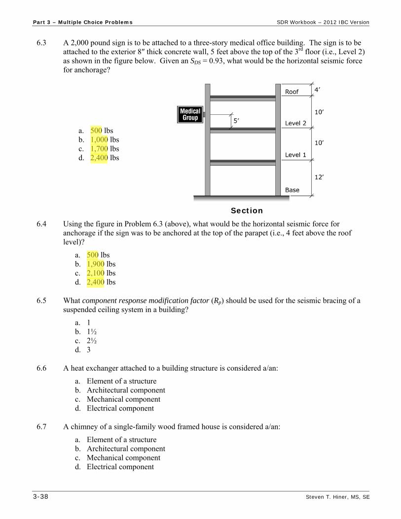
6.3 A 2,000 pound sign is to be attached to a three-story medical office building. The sign is to be attached to the exterior 8″ thick concrete wall, 5 feet above the top of the 3rd floor (i.e., Level 2) as shown in the figure below. Given an SDS = 0.93, what would be the horizontal seismic force for anchorage?
a. 500 lbs b. 1,000 lbs c. 1,700 lbs d. 2,400 lbs
Section
6.4 Using the figure in Problem 6.3 (above), what would be the horizontal seismic force for anchorage if the sign was to be anchored at the top of the parapet (i.e., 4 feet above the roof level)?
a. 500 lbs b. 1,900 lbs c. 2,100 lbs d. 2,400 lbs
6.5 What component response modification factor (Rp) should be used for the seismic bracing of a
suspended ceiling system in a building?
a. 1 b. 1½ c. 2½ d. 3
6.6 A heat exchanger attached to a building structure is considered a/an:
a. Element of a structure b. Architectural component c. Mechanical component d. Electrical component
6.7 A chimney of a single-family wood framed house is considered a/an:
a. Element of a structure b. Architectural component c. Mechanical component d. Electrical component
Steven Hiner
Highlight
Steven Hiner
Highlight
Steven Hiner
Highlight
Steven Hiner
Highlight
Steven Hiner
Highlight
Steven Hiner
Highlight
Steven Hiner
Highlight
Steven Hiner
Highlight

SDR Workbook – 2012 IBC Version Part 3 – Multiple Choice Problems
Steven T. Hiner, MS, SE 3-39
6.8 Given a 2000 lbs storage tank mounted on the roof of a Risk Category II building where SDS = 0.73, ap = 1 & Rp = 2½ … what is the seismic design force, Fp?
a. 700 lbs b. 1400 lbs c. 2000 lbs d. 2700 lbs
6.9 Below is a cross section through a large pipe supported from the concrete roof slab of a
Hospital where SDS = 0.95, Ip = 1.5, ap = 2½ & Rp = 9. The pipe and its contents weigh 100 plf and have lateral bracing at a spacing of 8 feet (i.e., 8'-0" o.c.). Calculate the axial force in the brace due to the seismic design force, Fp?
a. 50 lbs b. 80 lbs c. 380 lbs d. 540 lbs
Section
6.10 What component amplification factor (ap) should be used to design the required steel reinforcement size and spacing in a 4 foot tall concrete parapet, braced 3 feet above the roof level?
a. 1 b. 1¼ c. 1½ d. 2½
6.11 Given a mechanical component with an operating weight (Wp) of 1500 lbs and component
stiffness (Kp) of 3000 lbs/inch, what is the component period (Tp)?
a. 0.01 second b. 0.10 second c. 0.23 second d. 0.78 second
6.12 For masonry or concrete wall buildings, anchor straps (i.e., purlin anchors) at the boundaries of
floor and roof diaphragms are utilized to:
a. transfer gravity loads to the wall b. transfer diaphragm shear to the shear walls c. reduce shrinkage of wood joists d. secure the walls to the diaphragm
Steven Hiner
Highlight
Part 4 – Multiple Choice Solutions SDR Workbook – 2012 IBC Version
4-28 Steven T. Hiner, MS, SE
Problem Answer Reference / Solution
HEFD 6.10.1)(9.0 IBC (16-7) minimum axial, P = 0.9(35 kips + 0) + 1.0(– 28.3 kips) + 1.6(0) = 3.2 kips
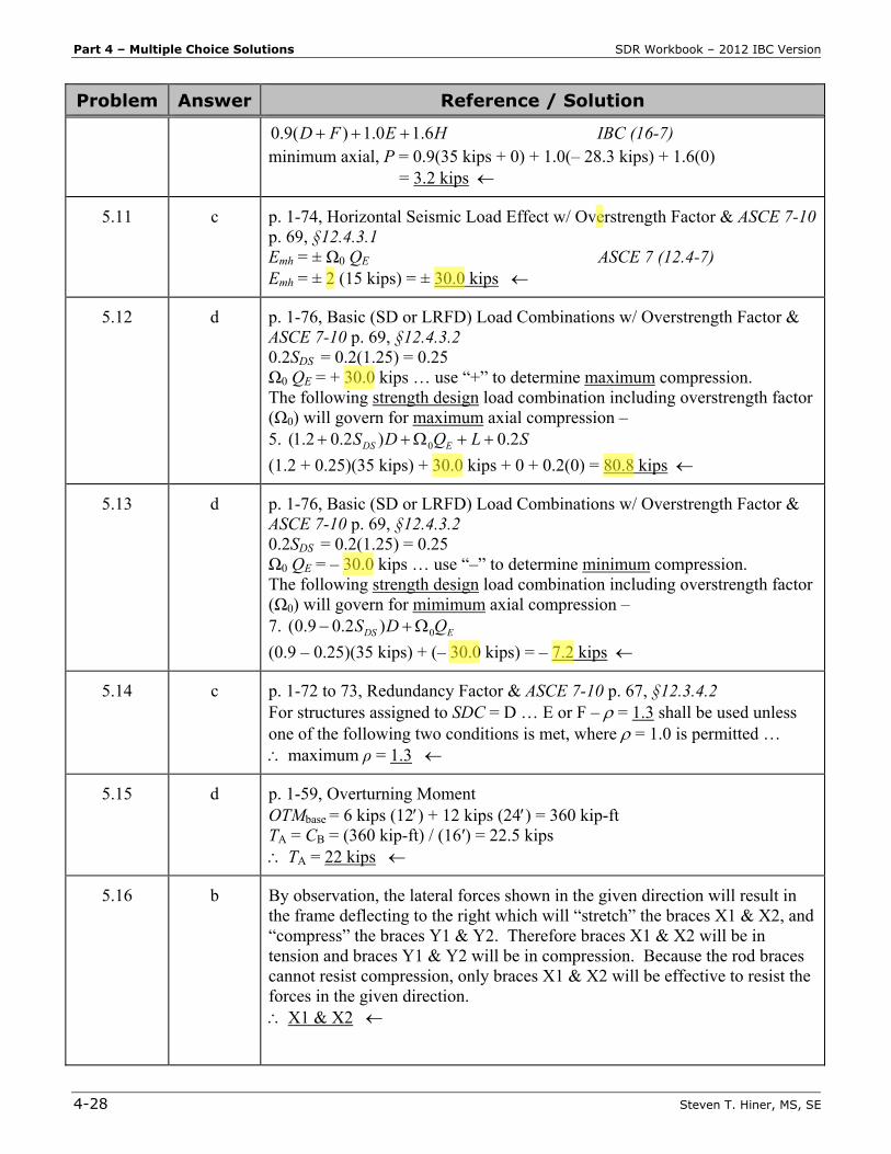
5.11 c p. 1-74, Horizontal Seismic Load Effect w/ Overstrength Factor & ASCE 7-10 p. 69, §12.4.3.1 Emh = ± Ω0 QE ASCE 7 (12.4-7) Emh = ± 2 (15 kips) = ± 30.0 kips
5.12 d p. 1-76, Basic (SD or LRFD) Load Combinations w/ Overstrength Factor & ASCE 7-10 p. 69, §12.4.3.2 0.2SDS = 0.2(1.25) = 0.25 Ω0 QE = + 30.0 kips … use “+” to determine maximum compression. The following strength design load combination including overstrength factor (Ω0) will govern for maximum axial compression – 5. SLQDS EDS 2.0)2.02.1( 0
(1.2 + 0.25)(35 kips) + 30.0 kips + 0 + 0.2(0) = 80.8 kips
5.13 d p. 1-76, Basic (SD or LRFD) Load Combinations w/ Overstrength Factor & ASCE 7-10 p. 69, §12.4.3.2 0.2SDS = 0.2(1.25) = 0.25 Ω0 QE = – 30.0 kips … use “–” to determine minimum compression. The following strength design load combination including overstrength factor (Ω0) will govern for mimimum axial compression – 7. EDS QDS 0)2.09.0(
(0.9 – 0.25)(35 kips) + (– 30.0 kips) = – 7.2 kips
5.14 c p. 1-72 to 73, Redundancy Factor & ASCE 7-10 p. 67, §12.3.4.2 For structures assigned to SDC = D … E or F – = 1.3 shall be used unless one of the following two conditions is met, where = 1.0 is permitted … maximum ρ = 1.3
5.15 d p. 1-59, Overturning Moment OTMbase = 6 kips (12) + 12 kips (24) = 360 kip-ft TA = CB = (360 kip-ft) / (16′) = 22.5 kips TA = 22 kips
5.16 b By observation, the lateral forces shown in the given direction will result in the frame deflecting to the right which will “stretch” the braces X1 & X2, and “compress” the braces Y1 & Y2. Therefore braces X1 & X2 will be in tension and braces Y1 & Y2 will be in compression. Because the rod braces cannot resist compression, only braces X1 & X2 will be effective to resist the forces in the given direction. X1 & X2
Owner
Highlight
Owner
Highlight
Owner
Highlight
Owner
Highlight
Owner
Highlight
Owner
Highlight
Owner
Highlight
Owner
Highlight
Owner
Highlight

SDR Workbook – 2012 IBC Version Part 4 – Multiple Choice Solutions
Steven T. Hiner, MS, SE 4-29
Problem Answer Reference / Solution
5.17 c X2 is the brace is the 2nd story and it will carry the entire 12 kip force as the horizontal component in that brace. The resultant axial (tension) force can be determined from Trigonometry. With a 12 story height and 16 bay spacing, the brace length will be 20 (i.e., 3-4-5 triangle … or 12-16-20). TX2 = (12 kips)(20) / (16) = 15 kips
5.18 c p. 1-72, Horizontal Seismic Load Effect & ASCE 7-10 p. 69, §12.4.2.1 QE = effects of horizontal seismic forces from V or Fp … The axial force in brace X2 is due to F2 (but not equal to F2), and the Fx forces are due to the base shear V, therefore the axial force in brace X2 is from V (but certainly not equal to V ). QE
5.19 d X1 is the brace is the 1st story and it will carry the entire (12 kip + 6 kip) force as the horizontal component in that brace. The resultant axial (tension) force can be determined from Trigonometry. With a 12 story height and 16 bay spacing, the brace length will be 20 (i.e., 3-4-5 triangle … or 12-16-20). TX1 = (18 kips)(20) / (16) = 22.5 kips ≈ 22 kips
5.20 c Per 5.19, brace X1 will carry the entire 18 kips of horizontal seismic force in the given direction, and that entire force will be transferred to support A. Shear at A, VA = 18 kips
5.21 a Per 5.19, brace Y1will carry none of the horizontal seismic force in the given direction because brace Y1 cannot resist compression forces. Shear at B, VB = 0 kips
5.22 a p. 1-72, Vertical Seismic Load Effect & ASCE 7-10 p. 69, §12.4.2.2 Ev = ± 0.2SDS D ASCE 7 (12.4-4) Ev = ± 0.2(0.72)(110 kips) = ± 15.8 kips ≈ ± 16 kips
5.23 d p. 1-72, Horizontal Seismic Load Effect & ASCE 7-10 p. 69, §12.4.2.1 Per 5.18 and 5.19, the axial force in brace X1 (TX1) is a QE force and is equal to 22.5 kips. QE = TX1 = 22.5 kips ρ = 1.3 (given) Eh = ρ QE ASCE 7 (12.4-3) Eh = 1.3(22.5 kips) = 29.2 kips ≈ 29 kips
6.1 d p. 1-84 & ASCE 7-10 p. 91, Table 13.5-1 - Architectural Component Cantilever Elements (Unbraced …) - parapets – ap = 2½
6.2 b ASCE 7-10 p. 91 & 93, Tables 13.5-1 and 13.6-1 Footnote c – overtsrength as required for anchorage to concrete
6.3 c p. 1-82, Seismic Design Force & ASCE 7-10 p. 88 & 89, §13.3.1 (continued)
Owner
Highlight

Part 4 – Multiple Choice Solutions SDR Workbook – 2012 IBC Version
4-30 Steven T. Hiner, MS, SE
Problem Answer Reference / Solution
SDS = 0.93 (given) ap = 2½ & Rp = 3 – Table 13.5-1 - Signs & Billboards z = 12′ + 10′ + 5′ = 27′ h = hn = 12′ + 2(10′) = 32′ (z / h) = 27′ / 32′ = 0.84 Ip = 1.0 – ASCE 7-10 – §13.1.3 Rp /Ip = (3 / 1.0) = 3
h
z
IR
WSaF
PP
pDSpp 21
4.0 ASCE 7 (13.3-1)
= 0.4(2.5)(0.93) Wp [1 + 2 (0.84)] / (3) = 0.83 Wp (governs)
maximum ppDSp WISF 6.1 ASCE 7 (13.3-2)
= 1.6(0.93)(1.0) Wp = 1.49 Wp
minimum ppDSp WISF 3.0 ASCE 7 (13.3-3)
= 0.3(0.93)(1.0) Wp = 0.28 Wp
Fp = 0.83(2,000 lbs) = 1,660 lbs ≈ 1,700 lbs
6.4 b p. 1-82, Seismic Design Force & ASCE 7-10 p. 88 & 89, §13.3.1 SDS = 0.93 (given) ap = 2½ & Rp = 3 – Table 13.5-1 - Signs & Billboards z = h + 4′ parapet? … no, because ASCE 7-10 – §13.3.1 states that “the value of z / h need not exceed 1.0” use (z / h) = 1.0 Ip = 1.0 – ASCE 7-10 – §13.1.3 Rp/Ip = (3 / 1.0) = 3
h
z
IR
WSaF
PP
pDSpp 21
4.0 ASCE 7 (13.3-1)
= 0.4(2.5)(0.93) Wp [1 + 2(1.0)] / (3) = 0.93 Wp (governs)
maximum ppDSp WISF 6.1 ASCE 7 (13.3-2)
= 1.6(0.93)(1.0) Wp = 1.49 Wp
minimum ppDSp WISF 3.0 ASCE 7 (13.3-3)
= 0.3(0.93)(1.0) Wp = 0.28 Wp
Fp = 0.93(2,000 lbs) = 1,860 lbs ≈ 1,900 lbs
6.5 c p. 1-85 & ASCE 7-10 p. 91, Table 13.5-1 – Architectrural Components Ceilings (All) – Rp = 2½
6.6 c p. 1-86 & ASCE 7-10 p. 93, Table 13.6-1 – Mechanical & Electrical Components Heat exchanger = mechanical component
Steven Hiner
Highlight
Steven Hiner
Highlight
Steven Hiner
Highlight
Steven Hiner
Highlight
Steven Hiner
Highlight
Steven Hiner
Highlight
Steven Hiner
Highlight
Steven Hiner
Highlight
Steven Hiner
Highlight
Steven Hiner
Highlight
Steven Hiner
Highlight
Steven Hiner
Highlight
Steven Hiner
Highlight
Steven Hiner
Highlight

SDR Workbook – 2012 IBC Version Part 4 – Multiple Choice Solutions
Steven T. Hiner, MS, SE 4-31
Problem Answer Reference / Solution
6.7 b p. 1-85 & ASCE 7-10 p. 91, Table 13.5-1 – Architectrural Components Chimney (as part of a “house”) = architectural component
6.8 a p. 1-82, Seismic Design Force & & ASCE 7-10 p. 88 & 89, §13.3.1 SDS = 0.73, ap = 1 & Rp = 2½ (given) z/h = 1.0 – since tank is anchored on the roof (i.e., z = h) Ip = 1.0 – ASCE 7-10 – §13.1.3 Rp/Ip = (2½ / 1.0) = 2½
h
z
IR
WSaF
PP
pDSpp 21
4.0 ASCE 7 (13.3-1)
= 0.4(1)(0.73) Wp [1 + 2(1.0)] / (2½) = 0.35 Wp (governs)
maximum ppDSp WISF 6.1 ASCE 7 (13.3-2)
= 1.6(0.73)(1.0) Wp = 1.17 Wp
minimum ppDSp WISF 3.0 ASCE 7 (13.3-3)
= 0.3(0.73)(1.0) Wp = 0.22 Wp
Fp = 0.35(2,000 lbs) = 700 lbs
6.9 d p. 1-82, Seismic Design Force & ASCE 7-10 p. 88 & 89, §13.3.1 SDS = 0.95, Ip = 1.5, ap = 2½ & Rp = 9 (given) z/h = 1.0 – since pipe is suspended from, and braced to, the roof (i.e., z = h) Rp/Ip = (9 / 1.5) = 6.0
h
z
IR
WSaF
PP
pDSpp 21
4.0 ASCE 7 (13.3-1)
= 0.4(2.5)(0.95) Wp [1 + 2 (1.0)] / (6.0) = 0.48 Wp (governs)
maximum ppDSp WISF 6.1 ASCE 7 (13.3-2)
= 1.6(0.95)(1.5) Wp = 2.28 Wp
minimum ppDSp WISF 3.0 ASCE 7 (13.3-3)
= 0.3(0.95)(1.5) Wp = 0.43 Wp
Fp = 0.48(100 plf) = 48 plf
Horizontal component in brace, H = Fp (8′ o.c.) = 48 plf (8′) = 384 lbs/brace Resultant axial force in brace -
22 HR (384 lbs/brace) = 540 lbs/brace
6.10 a p. 1-85 & ASCE 7-10 p. 91, Table 13.5-1 – Architectural Component Cantilever elements (braced above its C.M.) - parapets – ap = 1
6.11 c p. 1-86 & ASCE 7-10 p. 94, §13.6.2 – Component Period Wp = 1500 lbs & Kp = 3000 lbs/inch (given)
(continued)
Steven Hiner
Highlight
Steven Hiner
Highlight

Part 4 – Multiple Choice Solutions SDR Workbook – 2012 IBC Version
4-32 Steven T. Hiner, MS, SE
Problem Answer Reference / Solution
g = 386.4 in/sec2
gK
WT
p
pp 2 ASCE 7 (13.6-1)
)4.386)(3000(
15002 = 0.23 second
6.12 d p. 1-92, Figure 6.6b Purlin anchors secure the walls to the diaphragm to resist out-of-plane loads
6.13 a p. 1-86 & ASCE 7-10 p. 93, Table 13.6-1 – Mechanical & Electrical Components Boiler – ap = 1 & Rp = 2½
6.14 d p. 1-88 & ASCE 7-10 p. 76, §12.11.2.1 – Wall Anchorage Forces Fp shall not be less than 0.2 Ka Ie Wp
6.15 b p. 1-88 & ASCE 7-10 p. 76, §12.11.2.1 – Wall Anchorage Forces Structural walls shall be designed to resist bending between anchors where the anchor spacing exceeds 4 feet
6.16 c p. 1-87 & ASCE 7-10 p. 76, §12.11.1 – Design for Out-of-Plane Forces Ie = 1.5 – ASCE 7-10 p. 4, Table 1.5-2 for Police Station (RC = IV) Structural walls shall be designed for a force normal to the surface (i.e., out-of-plane load) of: Fp = 0.4 SDS Ie Wwall = 0.4(0.62)(1.5)(100 psf) = 37 psf governs 0.10 Wwall minimum = 0.10(100 psf) = 10 psf
Fp = 37 psf
6.17 c p. 1-88 & ASCE 7-10 p. 76, §12.11.2.1 – Wall Anchorage Forces SDS = 1.13 (given) Lf = 0 for rigid diaphragms
1000.1 f
a
LK = 1.0 + (0 / 100) = 1.0
Ie = 1.25 – ASCE 7-10 p. 4, Table 1.5-2 for Jails (RC = III) Wp = pwwall hhW 2 … for (one-story) walls with a parapet
= (85 psf)(14′/2 + 3′) = 850 plf
peaDSp WIKSF 4.0 ASCE 7 (12.11-1)
= 0.4(1.13)(1.0)(1.25)(850 plf) = 480 plf governs
peap WIKF 2.0 minimum
= 0.2(1.0)(1.25)(850 plf) = 212 plf minimum
Fp = 480 plf
Owner
Highlight
Owner
Highlight

Part 4 – Multiple Choice Solutions SDR Workbook – 2012 IBC Version
4-34 Steven T. Hiner, MS, SE
Problem Answer Reference / Solution
ap = 1 & Rp = 2½ – ASCE 7-10 – Table 13.6-1 - Compressors z = h1 = 10′ … since 2nd floor level = Level 1 (i.e., first level above the base) h = hn = 10 stories (10′ / story) = 100′ z/h = 10′ / 100′ = 0.10 Ip = 1.0 – ASCE 7-10 – §13.1.3 Rp/Ip = (2½ / 1.0) = 2½
h
z
IR
WSaF
PP
pDSpp 21
4.0 ASCE 7 (13.3-1)
= 0.4(1)(0.73) Wp [1 + 2(0.10)] / (2½) = 0.14 Wp
maximum ppDSp WISF 6.1 ASCE 7 (13.3-2)
= 1.6(0.73)(1.0) Wp = 1.17 Wp
minimum ppDSp WISF 3.0 ASCE 7 (13.3-3)
= 0.3(0.73)(1.0) Wp = 0.22 Wp governs
Fp = 0.22(10,000 lbs) = 2,200 lbs
6.24 c p. 1-82, Seismic Design Force & ASCE 7-10 p. 88 & 89, §13.3.1 SDS = 0.83 (given) ap = 2½ & Rp = 3 – ASCE 7-10 – Table 13.5-1 – Signs & Billboards z/h = 1.0 – since Billboard is anchored to the roof (i.e., z = h) Ip = 1.0 – ASCE 7-10 – §13.1.3 Rp/Ip = (3 / 1.0) = 3
h
z
IR
WSaF
PP
pDSpp 21
4.0 ASCE 7 (13.3-1)
= 0.4(2½)(0.83) Wp [1 + 2(1.0)] / (3) = 0.83 Wp governs
maximum ppDSp WISF 6.1 ASCE 7 (13.3-2)
= 1.6(0.83)(1.0) Wp = 1.33 Wp
minimum ppDSp WISF 3.0 ASCE 7 (13.3-3)
= 0.3(0.83)(1.0) Wp = 0.25 Wp
Fp = 0.83(10 kips) = 8.3 kips
6.25 c p. 1-84 & ASCE 7-10 p. 50, §11.2 – Component, Rigid Nonstructural component having a fundamental period less than or equal to 0.06 s. 0.06 second
6.26 d ASCE 7-10 p. 91, §13.5.6.1 – Seismic Forces The weight of the ceiling, Wp , ... shall be taken as not less than 4 psf. 4 psf
6.27 c p. 1-81, Component Importance Factor & ASCE 7-10 p. 87, §13.1.3 - item 1 (continued)
Owner
Highlight
Part 4 – Multiple Choice Solutions SDR Workbook – 2012 IBC Version
4-40 Steven T. Hiner, MS, SE
Problem Answer Reference / Solution
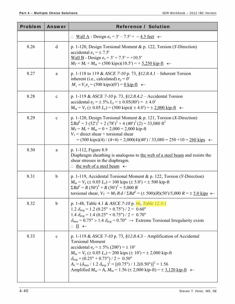
Wall A - Design ex = 3′ – 7.5′ = 4.5 feet
8.26 d p. 1-120, Design Torsional Moment & p. 122, Torsion (Y-Direction) accidental ex = 7.5′ Wall B - Design ex = 3′ + 7.5′ = +10.5′ MT = Mt + Mta = (500 kips)(10.5′) = + 5,250 kip-ft
8.27 a p. 1-118 to 119 & ASCE 7-10 p. 73, §12.8.4.1 – Inherent Torsion inherent (i.e., calculated) ey = 0′
yxt eVM = (500 kips)(0′) = 0 kip-ft
8.28 c p. 1-119 & ASCE 7-10 p. 73, §12.8.4.2 – Accidental Torsion accidental ey = 5% Ly = 0.05(80′) = 4.0′ Mta = Vx ( 0.05 Ly) = (500 kips)( 4.0′) = 2,000 kip-ft
8.29 c p. 1-120, Design Torsional Moment & p. 121, Torsion (X-Direction) Rd2 = 3 (52)2 + 2 (78)2 + 4 (40)2 (2) = 33,080 ft2 MT = Mt + Mta = 0 + 2,000 = 2,000 kip-ft V1 = direct shear + torsional shear = (500 kips)(4) / (4+4) + 2,000(4)(40) / 33,080 = 250 +10 = 260 kips
8.30 a p. 1-112, Figure 8.9 Diaphragm sheathing is analogous to the web of a steel beam and resists the shear stresses in the diaphragm. the web of a steel beam
8.31 b p. 1-119, Accidental Torsional Moment & p. 122, Torsion (Y-Direction) Mta = Vy ( 0.05 Lx) = 100 kips ( 5.0′) = 500 kip-ft Rd2 = R (50′)2 + R (50′)2 = 5,000 R torsional shear, VT = MT R d / Rd2 = ( 500)(R)(50′)/5,000 R = 5.0 kips
8.32 b p. 1-48, Table 4.1 & ASCE 7-10 p. 66, Table 12.3-1 1.2 avg = 1.2 (0.25" + 0.75") / 2 = 0.60" 1.4 avg = 1.4 (0.25" + 0.75") / 2 = 0.70" max = 0.75" 1.4 avg = 0.70" → Extreme Torsional Irregularity exists II
8.33 c p. 1-119 & ASCE 7-10 p. 73, §12.8.4.3 – Amplification of Accidental Torsional Moment accidental ey = 5% (200′) = 10′ Mta = Vy ( 0.05 Lx) = 200 kips ( 10′) = 2,000 kip-ft avg = (0.25" + 0.75") / 2 = 0.50" Ax = (max / 1.2 avg )
2 = [(0.75") / 1.2(0.50")]2 = 1.56 Amplified Mta = Ax Mta = 1.56 ( 2,000 kip-ft) = 3,120 kip-ft
Owner
Highlight
Owner
Highlight

SDR Workbook – 2012 IBC Version Part 4 – Multiple Choice Solutions
Steven T. Hiner, MS, SE 4-47
Problem Answer Reference / Solution
9.9 b p. 1-144, Shear Wall Overturning / Hold-Downs = 1.0 (given) V1 = V2 = V / 2 = 33.6 kips / 2 = 16.8 kips
'30
)'10)(8.16)(0.1(7.0)(7.0 1
b
hVT
= – 3.92 kips
for ASD, uplift T = 4.0 kips
9.10 b p. 1-130, Wood Structural Panel Diaphragms V = CS W = 0.196 W (given) For a single-story building – ws = fp1 = Fp1 / L = CS wp1 East-West: ws = 0.196 [(25 psf)(75′) + (15 psf)(12′/2) 4 walls] = 438 plf Vmax = ws L / 2 = (438 plf)(40′) / 2 = 8,760 lbs for ASD, roof = (0.7 Vmax) / d = 0.7 (8,760 lbs) / 75′ = 82 plf 80 plf
9.11 c p. 1-135, Table 9.5 & SDPWS p. 31, Table 4.3A
3/8″ rated sheathing w/ 8d common @ 2″ o.c. → s = 1060 plf
15/32″ Structural I w/ 10d common @ 6″ o.c. → s = 680 plf NG!
15/32″ Structural I w/ 10d common @ 4″ o.c. → s = 1020 plf NG!
15/32″ Structural I w/ 10d common @ 3″ o.c. → s = 1330 plf OK
15/32″ Structural I w/ 10d common @ 2″ o.c. → s = 1740 plf OK
use 15/32″ Structural I w/ 10d common @ 3″ o.c. = 1330 plf 1060 plf
9.12 d p. 1-131 to 132, Table 9.2 - 9.3 & SDPWS p. 18-20, Table 4.2A & 4.2C Load parallel to continuous panel joints = CASE 3 (weak direction)
15/32″ sheathing w/ 8d @ 6″ o.c. unblocked → Table 9.3 (4.2C) →
s = 360 plf → ASD = s / 2.0 = (360 plf) / 2.0 = 180 plf < 275 plf NG!
15/32″ sheathing w/ 10d @ 6″ o.c. unblocked → Table 9.3 (4.2C) →
s = 380 plf → ASD = s / 2.0 = (380 plf) / 2.0 = 190 plf < 275 plf NG!
15/32″ sheathing w/ 8d @ 6″ o.c. blocked → Table 9.2 (4.2A) →
s =540 plf → ASD = s / 2.0 = (540 plf) / 2.0 = 270 plf < 275 plf NG!
15/32″ sheathing w/ 10d @ 6″ o.c. blocked → Table 9.2 (4.2A) →
s = 580 plf → ASD = s / 2.0 = (580 plf) / 2.0 = 290 plf 275 plf OK
use 15/32″ sheathing w/ 10d common @ 6″ o.c.
9.13 d p. 1-110, Flexible Diaphragm Analysis V = CS W For a single-story building – ws = fp1 = Fp1 / L = CS wp1 N-S: ws = 0.20[20 psf (120′) + (15 psf) (16′/2 + 2.5′) 2 walls] = 543 plf ws = 540 plf
9.14 c p. 1-127, Diaphragm Aspect Ratios East-West: L / d = 120′ / 40′ = 3:1
Owner
Highlight
Owner
Highlight
Part 4 – Multiple Choice Solutions SDR Workbook – 2012 IBC Version
4-48 Steven T. Hiner, MS, SE
Problem Answer Reference / Solution
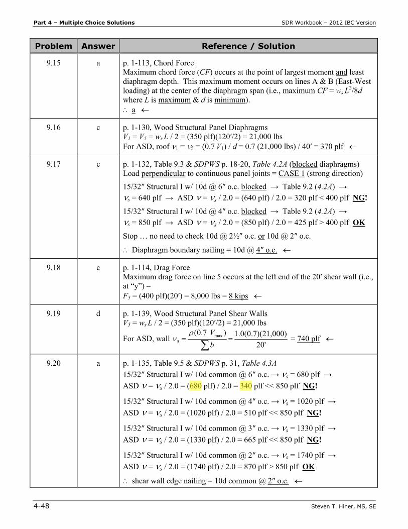
9.15 a p. 1-113, Chord Force Maximum chord force (CF) occurs at the point of largest moment and least diaphragm depth. This maximum moment occurs on lines A & B (East-West loading) at the center of the diaphragm span (i.e., maximum CF = ws L
2/8d where L is maximum & d is minimum). a
9.16 c p. 1-130, Wood Structural Panel Diaphragms V1 = V5 = ws L / 2 = (350 plf)(120′/2) = 21,000 lbs For ASD, roof 1 = 5 = (0.7 V1) / d = 0.7 (21,000 lbs) / 40′ = 370 plf
9.17 c p. 1-132, Table 9.3 & SDPWS p. 18-20, Table 4.2A (blocked diaphragms) Load perpendicular to continuous panel joints = CASE 1 (strong direction)
15/32″ Structural I w/ 10d @ 6″ o.c. blocked → Table 9.2 (4.2A) →
s = 640 plf → ASD = s / 2.0 = (640 plf) / 2.0 = 320 plf < 400 plf NG!
15/32″ Structural I w/ 10d @ 4″ o.c. blocked → Table 9.2 (4.2A) →
s = 850 plf → ASD = s / 2.0 = (850 plf) / 2.0 = 425 plf > 400 plf OK
Stop … no need to check 10d @ 2½″ o.c. or 10d @ 2″ o.c.
Diaphragm boundary nailing = 10d @ 4″ o.c.
9.18 c p. 1-114, Drag Force Maximum drag force on line 5 occurs at the left end of the 20′ shear wall (i.e., at “y”) – F5 = (400 plf)(20′) = 8,000 lbs = 8 kips
9.19 d p. 1-139, Wood Structural Panel Shear Walls V5 = ws L / 2 = (350 plf)(120′/2) = 21,000 lbs
For ASD, wall 20'
1,000)1.0(0.7)(2
)7.0( max5
b
V = 740 plf
9.20 a p. 1-135, Table 9.5 & SDPWS p. 31, Table 4.3A
15/32″ Structural I w/ 10d common @ 6″ o.c. → s = 680 plf →
ASD = s / 2.0 = (680 plf) / 2.0 = 340 plf << 850 plf NG!
15/32″ Structural I w/ 10d common @ 4″ o.c. → s = 1020 plf →
ASD = s / 2.0 = (1020 plf) / 2.0 = 510 plf << 850 plf NG!
15/32″ Structural I w/ 10d common @ 3″ o.c. → s = 1330 plf →
ASD = s / 2.0 = (1330 plf) / 2.0 = 665 plf << 850 plf NG!
15/32″ Structural I w/ 10d common @ 2″ o.c. → s = 1740 plf →
ASD = s / 2.0 = (1740 plf) / 2.0 = 870 plf > 850 plf OK
shear wall edge nailing = 10d common @ 2″ o.c.
Owner
Highlight
Owner
Highlight
Part 4 – Multiple Choice Solutions SDR Workbook – 2012 IBC Version
4-50 Steven T. Hiner, MS, SE
Problem Answer Reference / Solution
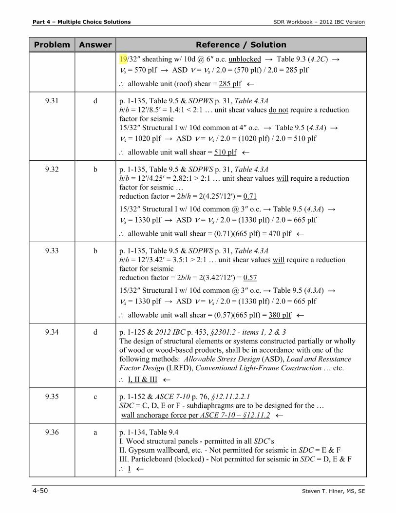
19/32″ sheathing w/ 10d @ 6″ o.c. unblocked → Table 9.3 (4.2C) →
s = 570 plf → ASD = s / 2.0 = (570 plf) / 2.0 = 285 plf
allowable unit (roof) shear = 285 plf
9.31 d p. 1-135, Table 9.5 & SDPWS p. 31, Table 4.3A h/b = 12′/8.5′ = 1.4:1 < 2:1 … unit shear values do not require a reduction factor for seismic 15/32″ Structural I w/ 10d common at 4″ o.c. → Table 9.5 (4.3A) →
s = 1020 plf → ASD = s / 2.0 = (1020 plf) / 2.0 = 510 plf
allowable unit wall shear = 510 plf
9.32 b p. 1-135, Table 9.5 & SDPWS p. 31, Table 4.3A h/b = 12′/4.25′ = 2.82:1 > 2:1 … unit shear values will require a reduction factor for seismic … reduction factor = 2b/h = 2(4.25′/12′) = 0.71
15/32″ Structural I w/ 10d common @ 3″ o.c. → Table 9.5 (4.3A) →
s = 1330 plf → ASD = s / 2.0 = (1330 plf) / 2.0 = 665 plf
allowable unit wall shear = (0.71)(665 plf) = 470 plf
9.33 b p. 1-135, Table 9.5 & SDPWS p. 31, Table 4.3A h/b = 12′/3.42′ = 3.5:1 > 2:1 … unit shear values will require a reduction factor for seismic reduction factor = 2b/h = 2(3.42′/12′) = 0.57
15/32″ Structural I w/ 10d common @ 3″ o.c. → Table 9.5 (4.3A) →
s = 1330 plf → ASD = s / 2.0 = (1330 plf) / 2.0 = 665 plf
allowable unit wall shear = (0.57)(665 plf) = 380 plf
9.34 d p. 1-125 & 2012 IBC p. 453, §2301.2 - items 1, 2 & 3 The design of structural elements or systems constructed partially or wholly of wood or wood-based products, shall be in accordance with one of the following methods: Allowable Stress Design (ASD), Load and Resistance Factor Design (LRFD), Conventional Light-Frame Construction … etc.
I, II & III
9.35 c p. 1-152 & ASCE 7-10 p. 76, §12.11.2.2.1 SDC = C, D, E or F - subdiaphragms are to be designed for the … wall anchorage force per ASCE 7-10 – §12.11.2
9.36 a p. 1-134, Table 9.4 I. Wood structural panels - permitted in all SDC’s II. Gypsum wallboard, etc. - Not permitted for seismic in SDC = E & F III. Particleboard (blocked) - Not permitted for seismic in SDC = D, E & F I
Owner
Highlight