Order guide Power supply and SEL-Bus system · The SEL-Bus cable that connects a unit to the...
16
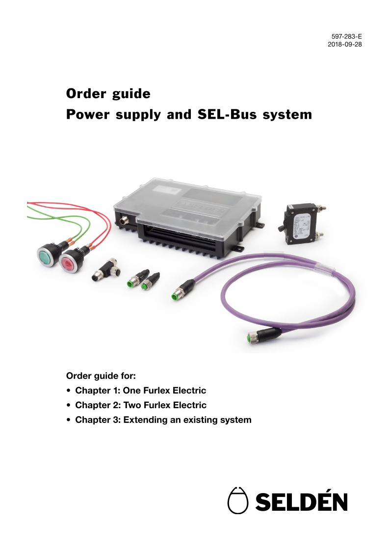
597-283-E 2018-09-28 Order guide Power supply and SEL-Bus system Order guide for: • Chapter 1: One Furlex Electric • Chapter 2: Two Furlex Electric • Chapter 3: Extending an existing system
Transcript of Order guide Power supply and SEL-Bus system · The SEL-Bus cable that connects a unit to the...
597-283-E2018-09-28
Order guide
Power supply and SEL-Bus system
Order guide for:
• Chapter 1: One Furlex Electric
• Chapter 2: Two Furlex Electric
• Chapter 3: Extending an existing system

Ill. Dan Ljungsvik/Seldén 2018
- +
Furlex Electric (motor unit). See separate manual.
Control button
Integrated main switch/fuse
Female terminalT-connector
Connection box
Motor control unit (MCU)
Battery
PSU
Male terminal
T-connector
Connection cables, 3m
SEL-Bus cables (Backbone)
SEL-Bus cables (Drop cable)
0,3m
10m
5m
1m0,3m
Power cables, 9m
2
1 Furlex Electric Standard PacksThe following parts and packages are recommended for the installation of one Furlex Electric, Table 1. For Installation of more than one unit, please continue to chapter 2 or chapter 3.
FURLEX ELECTRIC STANDARD PACKS
Part/package Qty Art. No. Comment
Power Supply Unit (PSU) 1 532-800-10 One PSU is required per complete installation
Integrated main switch/fuse 1 For 12V power532-488
For 24V power532-492
Can be replaced with custom switch/fuse
Control pack(table 2)
1 Furlex Electric 200/204 Genoa532-815-90
Furlex Electric 300/304 Genoa532-815-92
Can be replaced or extended by purchasing included parts separately
SEL-Bus Basic Pack(Table 3)
1 532-835-10 Can be extended by purchasing additional SEL-Bus cables and parts separately
Power Cable Pack(Table 4)
1 531-048-10 Can be replaced or extended by purchasing included parts separately
Table 1: Furlex Electric Standard packs

Panel, 2 push buttons
3
Included parts in Control pack, SEL-Bus Basic Pack and Power cable pack is listed in Table 2, 3, and 4.
Control Pack a) Furlex Electric 200/204 Genoa532-815-90
b) Furlex Electric 300/304 Genoa532-815-92
Included parts Quantity Art. No. Art. No.
Motor Control Unit (MCU) 1 532-815-20 532-815-21
Connection box 1 532-487-01 532-487-01
Control buttons 1 540-459-16 540-459-16
Connection cable Orange 3m 531-045 531-045
Connection cable Gray 3m 531-046 531-046
Connection cable Brown 3m 531-047 531-047
Stainless mounting panels for one or two control buttons are available as options and listed in table 5.
The SEL-Bus cables are available in fixed lengths, which is why it is important that you estimate how the system will be installed to see if any additional lengths are required. All available SEL-Bus cable lengths are listed in Table 5.
Buttons mounted in mounting panel, 540-462-01
Control buttons 540-459-16
Table 4: Art. No.s, power cables
If the total required power cable length (Pos+ and Neg-) between MCU and PSU is more than 18m, a larger cable size is needed (10mm2), as listed in Table 5.
Table 2 Art. No.s, Furlex Electric Control Pack.
Table 3 Art. No.s, SEL-Bus cable pack
SEL-Bus Basic pack for Furlex Electric: 532-835-10
Included parts Quantity Art. No.
Female Terminal 1 532-835
Male Terminal 1 532-836
T-connectors 3 532-839
SEL-Bus cable 0.3 m 2 531-101
SEL-Bus cable 1m 1 531-102
SEL-Bus cable 5 m 1 531-104
SEL-Bus cable 10 m 1 531-105
Power Cable pack for Furlex Electric: 531-048-10
Included parts Quantity Art. No.
Power Cable 6mm2 Blue 9m 531-049
Power Cable 6mm2 Yellow 9m 531-048

Custom order
Part Art. No. Unit
Panel 1 push button 540-461-01 Ea
Panel 2 push buttons 540-462-01 Ea
T-connector 532-839 Ea
Female Terminal 532-835 Ea
Male Terminal 532-836 Ea
Power Cable 6mm2 Blue 531-049 /meter
Power Cable 6mm2 Yellow 531-048 /meter
Power Cable 10mm2 Blue 531-051 /meter
Power Cable 10mm2 Yellow 531-050 /meter
Connection Cable Orange 531-045 /meter
Connection Cable Grey 531-046 /meter
Connection Cable Brown 531-047 /meter
SEL-Bus cable 0,3 m 531-101 Ea
SEL-Bus cable 1m 531-102 Ea
SEL-Bus cable 2m 531-103 Ea
SEL-Bus cable 5 m 531-104 Ea
SEL-Bus cable 10 m 531-105 Ea
4
Any of the Furlex Standard Packs can be replaced or extended by ordering custom parts and cables from Table 5.
Battery cables should follow the quality and color standard of the boat and are not provided by Seldén.
The panel must be used if the control buttons are installed in a laminate thicker than 5 mm.
Table 5 Art. No.s, custom order

Furlex Electric (motor unit). See separate manual.
Control buttons
Main switch/fuse
Connection box
Battery
PSU
T-connector
SEL-Bus cables (Backbone)
SEL-Bus cables (Drop cable)
Power cables
Connection cables
1. Make a sketch of where to locate all the units: Motor control units (MCU), -close to its respective motor unit, Power Supply Unit (PSU) -close to battery, and Control buttons.
MCU
Ill. Dan Ljungsvik/Seldén 2018
- +
5
2 Parts and cable lengths for multiple Motor UnitsFor installation of two Furlex Electric (Motor Units), the following five steps will provide the necessary Art. No.s for your installation. Quantity of parts and length of cables will depend on the number of Seldén motor units (Furlex Electric) that will be installed, as well as their position on the boat.
2. Basic parts 3. Control Pack 4. SEL-Bus cables 5. Power cables
Calculate number of required
T-connectors.
Choose switch/ fuse option
Order according to Table 6
Order 1 control pack for each respective Seldén motor unit according to section 2.2
Calculate required lengths of each Backbone and Drop cable
Calculate longest total lengths of Pos+ and Neg- power cables between MCU – PSU
Order according to Table 10 Choose required
cable size
Calculate total Pos+ and Neg- cable lengths, respectively
Order according to Table 11

Table 6: Art. No.s, custom order
6
2.1 Basic partsEvery installation needs 1 PSU, 1 female terminal, 1 male terminal and custom number of T-connectors. Number of required T-connectors depends on how many units that are connected to the system. In addition, a switch/fuse combination that is adapted for the battery power is available from Seldén.
Part Pieces Art. No.
PSU 1 532-800-10
Female Terminal 1 532-835
Male Terminal 1 532-836
T-connectors
One T-connector is needed for each Unit:
1 PSU + x MCU + x control buttons
532-839
Integrated switch/fuse
1
(custom option can be purchased from external distributor)
For 12V power
532-488
For 24V power
532-492
Illustration below shows an example of a SEL-Bus system with 2 MCU (e.g. Furlex for forestay, Furlex for cutter stay), 2 Control buttons and in total 5 T-connectors.
MCU MCU
PSU
Male Terminal T-Connector Female Terminal

7
2.2 Control PacksOne control pack is needed for each respective Seldén Motor Unit. Choose the right package for your Furlex size and control button label.
Table 7: Art. No.s Control Pack with Genoa buttons
Control Pack a) Furlex Electric 200/204Genoa532-815-90
b) Furlex Electric 300/304 Genoa532-815-92
Included parts Quantity Art. No. Art. No.
Motor Control Unit (MCU)
1 532-815-20 532-815-21
Connection box 1 532-487-01 532-487-01
Control buttonsGENOA
1 540-459-16 540-459-16
Connection cable Orange 3m 531-045 531-045
Connection cable Gray 3m 531-046 531-046
Connection cable Brown 3m 531-047 531-047
Table 8: Art. No.s Control Pack with Cutter buttons
Control Pack a) Furlex Electric 200/204Cutter 532-815-91
b) Furlex Electric 300/304Cutter 532-815-93
Included parts Quantity Art. No. Art. No.
Motor Control Unit (MCU)
1 532-815-20 532-815-21
Connection box 1 532-487-01 532-487-01
Control buttonsCUTTER
1 540-459-19 540-459-19
Connection cable Orange 3m 531-045 531-045
Connection cable Grey 3m 531-046 531-046
Connection cable Brown 3m 531-047 531-047
Stainless mounting panels for one or two control buttons are available and listed in table 9:
Table 9: Art. No.s Panels for Control Buttons
Part Art. No.
Panel 1 push button 540-461-01
Panel 2 push buttons 540-462-01
The panel must be used if the control buttons are installed in a laminate thicker than 5 mm.
Control buttons mounted in mounting panel, 540-462-01

8
2.3 SEL-Bus CablesThe SEL-Bus cables are only available in fixed lengths, which is why it is important that you estimate how the system will be installed. Calculate quantity and length of the SEL-Bus cables. The total length of all SEL-Bus cables must not exceed 70 m.
A1-A4: BackboneThe SEL-Bus cables that connect the T-connectors are called the “Backbone”. Calculate the lengths between the systems T-connectors. Note: T-connectors that are located close enough to be connected directly to each other do not need a cable.
B1-B3: Drop cableThe SEL-Bus cable that connects a unit to the backbone via a T-connector is called a Drop cable. Calculate the lengths between the connected units and respective T-connector. 1 m cable is included by default in the Control Buttons, calculate any extra cable length, if needed. Max length for each drop cable is 5 m.
A1 A2 A3
B2 B2 B2
B1
B3
MCU MCU
PSU
A4
B3

9
Recommended cable
In figure Connection Length 0.3m 1m 2m 5m 10m
A1 Backbone
SEL-Bus cable betweenT-connectors
A2
A3
A4
B1 PSU – T-connector
B2 MCU – T-connector
MCU – T-connector
B3 Control button – T-connector
Control button – T-connector
Total number of each cable (pcs)
531-101 531-102 531-103 531-104 531-105
Table 10: Art. No.s SEL-Bus cables
*This table is an example based on 2 connected motor units with 2 connected control buttons.

10
2.4 Power cablesCalculate the needed cable length between PSU and MCU. Add up the length of positive and negative cables for the MC unit that are located furthest away from the PSU to get the required cable size; if any of the total cable lengths is more than 18m, the larger cable size is needed. Power cables are purchased by the meter.
C1
C2
PSU
MCU MCU
Table 11: Art. No.s Power cables
In figure Connection Tot Length max 18 m Cable area 6mm2
Tot Length 18-40m Cable area 10mm2
Pos+ (Blue) Neg- (Yellow) Pos+ (blue) Neg- (yellow)
C1 PSU – MCU1
C2 MCU1 – MCU2 or PSU - MCU2
Total length of each cable (m)
531-049 531-048 531-051 531-050

11
3 Extension of an existing system with a
second Furlex ElectricFor the installation of a second Motor Unit (Furlex Electric), the following five steps will provide the necessary Art. No.s for your installation:
3.1 T-connectorsOne additional T-connector is needed for each new MCU and one for each new control button that is connected to the SEL-Bus system. Calculate number of required T-connectors.
2. T-connectors 3. Control Pack 4. SEL-Bus cables 5. Power cables
Calculate number of required T-connectors.
Order according to Table 12
Order the specific control pack for the new Seldén motor unit according to section 3.2
Calculate required lengths of each Backbone and Drop cable
Calculate longest total lengths of Pos+ and Neg- power cables between the new MCU and PSU
Order according to Table 16 Choose required
cable size
Calculate total Pos+ and Neg- cable lengths, respectively
Order according to Table 17
1. Estimate where the new MCU (and control button) will be installed in the boat. The MCU should be located close to the new Motor unit.
Part Pieces Art. No.
T-connector 532-839
Table 12: Art. No. T-connector

12
3.2 Control PacksOne additional control pack is needed for the new Seldén Motor Unit. Choose the right package for your Furlex size and control button label.
Control Pack a) Furlex Electric 200/204Genoa532-815-90
b) Furlex Electric 300/304 Genoa532-815-92
Included parts Quantity Art. No. Art. No.
Motor Control Unit (MCU)
1 532-815-20 532-815-21
Connection box 1 532-487-01 532-487-01
Control buttonsGENOA
1 540-459-16 540-459-16
Connection cable Orange 3m 531-045 531-045
Connection cable Grey 3m 531-046 531-046
Connection cable Brown 3m 531-047 531-047
Control Pack a) Furlex Electric 200/204Cutter532-815-91
b) Furlex Electric 300/304Cutter532-815-93
Included parts Quantity Art. No. Art. No.
Motor Control Unit (MCU)
1 532-815-20 532-815-21
Connection box 1 532-487-01 532-487-01
Control buttonsCUTTER
1 540-459-19 540-459-19
Connection cable Orange 3m 531-045 531-045
Connection cable Grey 3m 531-046 531-046
Connection cable Brown 3m 531-047 531-047
Table 13: Art. No.s Control Pack with Genoa buttons
Table 14: Art. No.s Control Pack with Cutter buttons
Table 15: Art. No.s Panels for Control Buttons
Part Art. No.
Panel 1 push button 540-461-01
Panel 2 push buttons 540-462-01
Stainless mounting panels for one or two control buttons are available as options and listed in table 15.
Control buttons mounted in mounting panel 540-462-01
The panel must be used if the control buttons are installed in a laminate thicker than 5 mm.
13
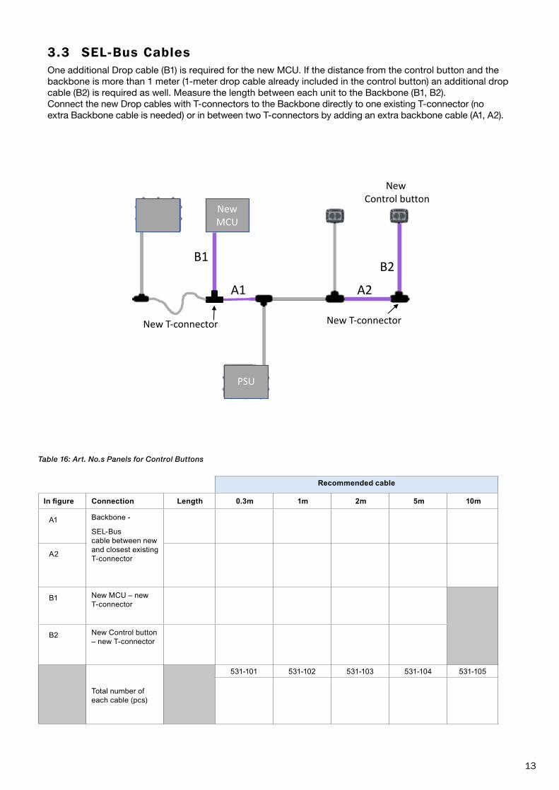
3.3 SEL-Bus CablesOne additional Drop cable (B1) is required for the new MCU. If the distance from the control button and the backbone is more than 1 meter (1-meter drop cable already included in the control button) an additional drop cable (B2) is required as well. Measure the length between each unit to the Backbone (B1, B2). Connect the new Drop cables with T-connectors to the Backbone directly to one existing T-connector (no extra Backbone cable is needed) or in between two T-connectors by adding an extra backbone cable (A1, A2).
B2
PSU
New MCU
A2
B2
New T-connector
B1
New T-connector
New Control button
A1
Recommended cable
In figure Connection Length 0.3m 1m 2m 5m 10m
A1 Backbone -
SEL-Bus cable between new and closest existing T-connectorA2
B1 New MCU – new T-connector
B2 New Control button – new T-connector
Total number of each cable (pcs)
531-101 531-102 531-103 531-104 531-105
Table 16: Art. No.s Panels for Control Buttons
14
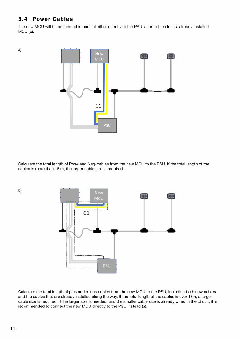
3.4 Power CablesThe new MCU will be connected in parallel either directly to the PSU (a) or to the closest already installed MCU (b).
a)
Calculate the total length of Pos+ and Neg-cables from the new MCU to the PSU. If the total length of the cables is more than 18 m, the larger cable size is required.
b)
Calculate the total length of plus and minus cables from the new MCU to the PSU, including both new cables and the cables that are already installed along the way. If the total length of the cables is over 18m, a larger cable size is required. If the larger size is needed, and the smaller cable size is already wired in the circuit, it is recommended to connect the new MCU directly to the PSU instead (a).
B2
PSU
New MCU
C1

15
Table 17: Art. No.s Power cables
In figure Connection Tot Length max 18 m Cable area 6mm2
Tot Length 18-40m Cable area 10mm2
Pos+ (Blue) Neg- (Yellow) Pos+ (blue) Neg- (yellow)
C1 PSU – MCU
Total length of each cable (m)
531-049 531-048 531-051 531-050

16
597-
283-
E
www.seldenmast.com