Orbitrap Elite Hardware Manual - Thermo Fisher :: Orbitrap
200
Part of Thermo Fisher Scientific Revision A - 1288170 Thermo Fisher Scientific Orbitrap Elite Hardware Manual
Transcript of Orbitrap Elite Hardware Manual - Thermo Fisher :: Orbitrap

Part of Thermo Fisher Scientific
Revision A - 1288170
Thermo Fisher Scientific
Orbitrap EliteHardware Manual

© 2011 Thermo Fisher Scientific Inc. All rights reserved.
Alconox is a registered trademark of Alconox, Inc. Convectron is a registered trademark of Helix Technology Corporation. Dremel is a registered trademark of the Robert Bosch Tool Corporation. Edwards and the Edwards logo are trademarks of Edwards Limited. HiPace is a trademark of Pfeiffer Vacuum Technology AG. Microsoft and Windows are registered trademarks of Microsoft Corporation. PEEK polymer is a trademark of Victrex plc. PEEKSil is a trademark of SGE International Pty. Ltd. SEQUEST is a registered trademark of University of Washington. Swagelok is a registered trademark of the Crawford Fitting Company. Teflon is a registered trademark of E. I. du Pont de Nemours & Co. Tygon is a registered trademark of Saint-Gobain Performance Plastics Company. Viton is a registered trademark of DuPont Performance Elastomers LLC.
All other trademarks are the property of Thermo Fisher Scientific Inc. and its subsidiaries.
Thermo Fisher Scientific Inc. provides this document to its customers with a product purchase to use in the product operation. This document is copyright protected and any reproduction of the whole or any part of this document is strictly prohibited, except with the written authorization of Thermo Fisher Scientific Inc.
The contents of this document are subject to change without notice. All technical information in this document is for reference purposes only. System configurations and specifications in this document supersede all previous information received by the purchaser.
Thermo Fisher Scientific Inc. makes no representations that this document is complete, accurate or error-free and assumes no responsibility and will not be liable for any errors, omissions, damage or loss that might result from any use of this document, even if the information in the document is followed properly.
This document is not part of any sales contract between Thermo Fisher Scientific Inc. and a purchaser. This document shall in no way govern or modify any Terms and Conditions of Sale, which Terms and Conditions of Sale shall govern all conflicting information between the two documents.
Release History: Revision A released in June 2011.
For Research Use Only. Not for use in diagnostic procedures.
Place Declaration of Conformity here
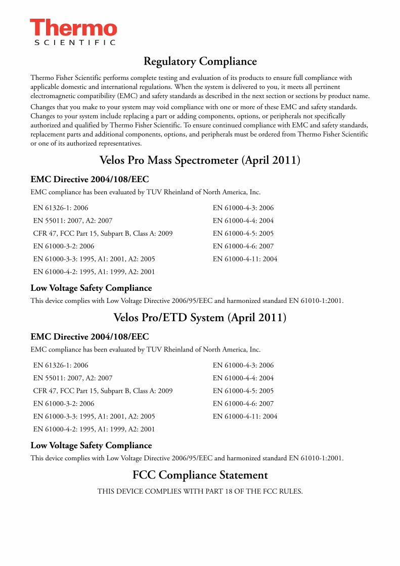
Regulatory ComplianceThermo Fisher Scientific performs complete testing and evaluation of its products to ensure full compliance with applicable domestic and international regulations. When the system is delivered to you, it meets all pertinent electromagnetic compatibility (EMC) and safety standards as described in the next section or sections by product name.Changes that you make to your system may void compliance with one or more of these EMC and safety standards. Changes to your system include replacing a part or adding components, options, or peripherals not specifically authorized and qualified by Thermo Fisher Scientific. To ensure continued compliance with EMC and safety standards, replacement parts and additional components, options, and peripherals must be ordered from Thermo Fisher Scientific or one of its authorized representatives.
Velos Pro Mass Spectrometer (April 2011)
EMC Directive 2004/108/EECEMC compliance has been evaluated by TUV Rheinland of North America, Inc.
Low Voltage Safety ComplianceThis device complies with Low Voltage Directive 2006/95/EEC and harmonized standard EN 61010-1:2001.
Velos Pro/ETD System (April 2011)
EMC Directive 2004/108/EECEMC compliance has been evaluated by TUV Rheinland of North America, Inc.
Low Voltage Safety ComplianceThis device complies with Low Voltage Directive 2006/95/EEC and harmonized standard EN 61010-1:2001.
FCC Compliance StatementTHIS DEVICE COMPLIES WITH PART 18 OF THE FCC RULES.
EN 61326-1: 2006 EN 61000-4-3: 2006
EN 55011: 2007, A2: 2007 EN 61000-4-4: 2004
CFR 47, FCC Part 15, Subpart B, Class A: 2009 EN 61000-4-5: 2005
EN 61000-3-2: 2006 EN 61000-4-6: 2007
EN 61000-3-3: 1995, A1: 2001, A2: 2005 EN 61000-4-11: 2004
EN 61000-4-2: 1995, A1: 1999, A2: 2001
EN 61326-1: 2006 EN 61000-4-3: 2006
EN 55011: 2007, A2: 2007 EN 61000-4-4: 2004
CFR 47, FCC Part 15, Subpart B, Class A: 2009 EN 61000-4-5: 2005
EN 61000-3-2: 2006 EN 61000-4-6: 2007
EN 61000-3-3: 1995, A1: 2001, A2: 2005 EN 61000-4-11: 2004
EN 61000-4-2: 1995, A1: 1999, A2: 2001

WEEE KonformitätDieses Produkt muss die EU Waste Electrical & Electronic Equipment (WEEE) Richtlinie 2002/96/EC erfüllen. Das Produkt ist durch folgendes Symbol gekennzeichnet:
Thermo Fisher Scientific hat Vereinbarungen getroffen mit Verwertungs-/Entsorgungsanlagen in allen EU-Mitgliederstaaten und dieses Produkt muss durch diese Firmen wiederverwertet oder entsorgt werden. Mehr Informationen über die Einhaltung dieser Anweisungen durch Thermo Fisher Scientific, die Verwerter und Hinweise die Ihnen nützlich sein können, die Thermo Fisher Scientific Produkte zu identifizieren, die unter diese RoHS Anweisung fallen, finden Sie unter www.thermo.com/WEEERoHS.
WEEE ComplianceThis product is required to comply with the European Union’s Waste Electrical & Electronic Equipment (WEEE) Directive 2002/96/EC. It is marked with the following symbol:
Thermo Fisher Scientific has contracted with one or more recycling/disposal companies in each EU Member State, and this product should be disposed of or recycled through them. Further information on Thermo Fisher Scientific’s compliance with these Directives, the recyclers in your country, and information on Thermo Fisher Scientific products which may assist the detection of substances subject to the RoHS Directive are available at www.thermo.com/WEEERoHS.

Conformité DEEECe produit doit être conforme à la directive européenne (2002/96/EC) des Déchets d'Equipements Electriques et Electroniques (DEEE). Il est marqué par le symbole suivant:
Thermo Fisher Scientific s'est associé avec une ou plusieurs compagnies de recyclage dans chaque état membre de l’union européenne et ce produit devrait être collecté ou recyclé par celles-ci. Davantage d'informations sur la conformité de Thermo Fisher Scientific à ces directives, les recycleurs dans votre pays et les informations sur les produits Thermo Fisher Scientific qui peuvent aider la détection des substances sujettes à la directive RoHS sont disponibles sur www.thermo.com/WEEERoHS.

Thermo Fisher Scientific Orbitrap Elite Hardware Manual (P/N 1288170, Revision A) i
Read This First
Welcome to the Thermo Scientific Orbitrap Elite system! The Orbitrap Elite is a member of the family of LTQ™ mass spectrometer (MS) hybrid instruments.
All information in this guide concerning the Orbitrap Elite mass spectrometer also applies to the Orbitrap Elite ETD system where the ETD Module is physically coupled to the back of the Orbitrap Elite mass spectrometer.
About This GuideThis Orbitrap Elite Hardware Manual contains a description of the modes of operation and principle hardware components of your Orbitrap Elite instrument. In addition, this manual provides step-by-step instructions for cleaning and maintaining your instrument.
Who Uses This Guide
This Orbitrap Elite Hardware Manual is intended for all personnel that need a thorough understanding of the instrument (to perform maintenance or troubleshooting, for example). This manual should be kept near the instrument to be available for quick reference.
Scope of This Guide
This manual includes the following chapters:
• Chapter 1: “Functional Description” describes the principal components of the Orbitrap Elite mass spectrometer.
• Chapter 2: “Basic System Operations” provides procedures for shutting down and starting up the Orbitrap Elite mass spectrometer.
• Chapter 3: “User Maintenance” outlines the maintenance procedures that you should perform on a regular basis to maintain optimum instrument performance.
• Chapter 4: “Replaceable Parts” lists the replaceable parts for mass spectrometer and data system.
• Appendix A: “Fluoranthene” describes properties of the reagent that is used in the ETD Module portion of the Orbitrap Elite ETD mass spectrometer.

Read This FirstRelated Documentation
ii Orbitrap Elite Hardware Manual (P/N 1288170, Revision A) Thermo Fisher Scientific
Related DocumentationIn addition to this guide, Thermo Fisher Scientific provides the following documents for Orbitrap Elite mass spectrometer and Orbitrap Elite ETD mass spectrometer:
• LTQ Orbitrap Series Preinstallation Requirements Guide
• Orbitrap Elite Getting Started Guide
• Velos Pro manual set
You can access PDF files of the documents listed above and of this guide from the data system computer. The software also provides Help.
To view product manuals
1. From the Microsoft™ Windows™ taskbar, choose Start > Programs > Thermo Instruments > LTQ > Manuals > model.
2. Click the PDF file that you want to view.

Read This FirstContacting Us
Thermo Fisher Scientific Orbitrap Elite Hardware Manual (P/N 1288170, Revision A) iii
Contacting UsThere are several ways to contact Thermo Fisher Scientific.
Assistance
For technical support and ordering information, visit us on the Web:
www.thermoscientific.com/ms
Service contact details for customers in Europe are available under:
www.thermoscientific.com/euservicecontact
Customer Information Service
cis.thermo-bremen.com is the Customer Information Service site aimed at providing instant access to
• Latest software updates
• Manuals, application reports, and brochures
Thermo Fisher Scientific recommends that you register with the site as early as possible. To register, visit register.thermo-bremen.com/form/cis and fill in the registration form. Once your registration has been finalized, you will receive confirmation by e-mail.
Changes to the Manual
To suggest changes to this manual
• Please send your comments (in German or English) to:
Editors, Technical DocumentationThermo Fisher Scientific (Bremen) GmbHHanna-Kunath-Str. 11
28199 Bremen
Germany
• Send an e-mail message to the Technical Editor at
You are encouraged to report errors or omissions in the text or index.Thank you.

Read This FirstTypographical Conventions
iv Orbitrap Elite Hardware Manual (P/N 1288170, Revision A) Thermo Fisher Scientific
Typographical ConventionsThis section describes typographical conventions that have been established for Thermo Fisher Scientific manuals.
Data Input
Throughout this manual, the following conventions indicate data input and output via the computer:
• Messages displayed on the screen are represented by capitalizing the initial letter of each word and by italicizing each word.
• Input that you enter by keyboard is identified by quotation marks: single quotes for single characters, double quotes for strings.
• For brevity, expressions such as “choose File > Directories” are used rather than “pull down the File menu and choose Directories.”
• Any command enclosed in angle brackets < > represents a single keystroke. For example, “press <F1>” means press the key labeled F1.
• Any command that requires pressing two or more keys simultaneously is shown with a plus sign connecting the keys. For example, “press <Shift> + <F1>” means press and hold the <Shift> key and then press the <F1> key.
• Any button that you click on the screen is represented in bold face letters. For example, “click Close”.
Topic Headings
The following headings are used to show the organization of topics within a chapter:
Chapter 1 Chapter Name
Second Level Topics
Third Level Topics
Fourth Level Topics

Read This FirstSafety and EMC Information
Thermo Fisher Scientific Orbitrap Elite Hardware Manual (P/N 1288170, Revision A) v
Safety and EMC InformationIn accordance with our commitment to customer service and safety, this instrument has satisfied the requirements for the European CE Mark including the Low Voltage Directive.
Designed, manufactured and tested in an ISO9001 registered facility, this instrument has been shipped to you from our manufacturing facility in a safe condition.
This instrument must be used as described in this manual. Any use of this instrument in a manner other than described here may result in instrument damage and/or operator injury.
Notice on Lifting and Handling of Thermo Scientific Instruments
For your safety, and in compliance with international regulations, the physical handling of this Thermo Scientific instrument requires a team effort for lifting and/or moving the instrument. This instrument is too heavy and/or bulky for one person alone to handle safely.
Notice on the Proper Use of Thermo Scientific Instruments
In compliance with international regulations: If this instrument is used in a manner not specified by Thermo Fisher Scientific, the protection provided by the instrument could be impaired.
Notice on the Susceptibility to Electromagnetic Transmissions
Your instrument is designed to work in a controlled electromagnetic environment. Do not use radio frequency transmitters, such as mobile phones, in close proximity to the instrument.
Safety and Special Notices
Make sure you follow the precautionary statements presented in this guide. The safety and other special notices appear different from the main flow of text. Safety and special notices include the following:
Caution Cautions highlight information necessary to protect your instrument from damage.
Note Notes highlight information that can affect the quality of your data. In addition, notes often contain information that you might need if you are having trouble.
Warning Warnings highlight hazards to human beings. Each Warning is accompanied by a Warning symbol.
Read This FirstSafety and EMC Information
vi Orbitrap Elite Hardware Manual (P/N 1288170, Revision A) Thermo Fisher Scientific
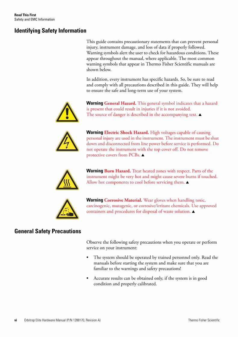
Identifying Safety Information
This guide contains precautionary statements that can prevent personal injury, instrument damage, and loss of data if properly followed. Warning symbols alert the user to check for hazardous conditions. These appear throughout the manual, where applicable. The most common warning symbols that appear in Thermo Fisher Scientific manuals are shown below.
In addition, every instrument has specific hazards. So, be sure to read and comply with all precautions described in this guide. They will help to ensure the safe and long-term use of your system.
General Safety Precautions
Observe the following safety precautions when you operate or perform service on your instrument:
• The system should be operated by trained personnel only. Read the manuals before starting the system and make sure that you are familiar to the warnings and safety precautions!
• Accurate results can be obtained only, if the system is in good condition and properly calibrated.
Warning General Hazard. This general symbol indicates that a hazard is present that could result in injuries if it is not avoided. The source of danger is described in the accompanying text.
Warning Electric Shock Hazard. High voltages capable of causing personal injury are used in the instrument. The instrument must be shut down and disconnected from line power before service is performed. Do not operate the instrument with the top cover off. Do not remove protective covers from PCBs.
Warning Burn Hazard. Treat heated zones with respect. Parts of the instrument might be very hot and might cause severe burns if touched. Allow hot components to cool before servicing them.
Warning Corrosive Material. Wear gloves when handling toxic, carcinogenic, mutagenic, or corrosive/irritant chemicals. Use approved containers and procedures for disposal of waste solution.
Read This FirstSafety and EMC Information
Thermo Fisher Scientific Orbitrap Elite Hardware Manual (P/N 1288170, Revision A) vii
• Service by the customer should be performed by trained qualified personnel only and should be restricted to servicing mechanical parts! Service on electronic parts should be performed by Thermo Fisher Scientific field service engineers only!
• Before plugging in any of the instrument modules or turning on the power, always make sure that the voltage and fuses are set appropriately for your local line voltage.
• Only use fuses of the type and current rating specified. Do not use repaired fuses and do not short-circuit the fuse holder.
• The supplied power cord must be inserted into a power outlet with a protective earth contact (ground). When using an extension cord, make sure that the cord also has an earth contact.
• Do not change the external or internal grounding connections.Tampering with or disconnecting these connections could endanger you and/or damage the system.
• The instrument is properly grounded in accordance with regulations when shipped. You do not need to make any changes to the electrical connections or to the instrument’s chassis to ensure safe operation.
• Never run the system without the housing on. Permanent damage can occur. When leaving the system, make sure that all protective covers and doors are properly connected and closed, and that heated areas are separated and marked to protect for unqualified personnel!
• Do not turn the instrument on if you suspect that it has incurred any kind of electrical damage. Instead, disconnect the power cord and contact a Thermo Fisher Scientific field service engineer for a product evaluation. Do not attempt to use the instrument until it has been evaluated. (Electrical damage may have occurred if the system shows visible signs of damage, or has been transported under severe stress.)
• Damage can also result if the instrument is stored for prolonged periods under unfavorable conditions (for example, subjected to heat, water, etc.).
• Always disconnect the power cord before attempting any type of maintenance.
• Capacitors inside the instrument may still be charged even if the instrument is turned off.
• Never try to repair or replace any component of the system that is not described in this manual without the assistance of your Thermo Fisher Scientific field service engineer.

Read This FirstSafety and EMC Information
viii Orbitrap Elite Hardware Manual (P/N 1288170, Revision A) Thermo Fisher Scientific
• Do not place any objects upon the instrument—especially not containers with liquids—unless it is requested by the user documentation. Leaking liquids might get into contact with electronic components and cause a short circuit.
Safety Advice for Possible Contamination
Hazardous Material Might Contaminate Certain Parts of Your System During Analysis.
In order to protect our employees, we ask you to adhere to special precautions when returning parts for exchange or repair.
If hazardous materials have contaminated mass spectrometer parts, Thermo Fisher Scientific can only accept these parts for repair if they have been properly decontaminated. Materials that due to their structure and the applied concentration might be toxic or that are reported in publications to be toxic are regarded as hazardous. Materials that will generate synergetic hazardous effects in combination with other present materials are also considered hazardous.
Your signature on the Health and Safety Form confirms that the returned parts have been decontaminated and are free of hazardous materials. Download the form from decon.thermo-bremen.com or order it from the Thermo Fisher Scientific field service engineer.
Parts contaminated by radioisotopes should not be returned to Thermo Fisher Scientific—neither under warranty nor within the exchange part program. If unsure about parts of the system possibly being contaminated by hazardous material, please make sure the Thermo Fisher Scientific field service engineer is informed before the engineer starts working on the system.

Thermo Fisher Scientific Orbitrap Elite Hardware Manual (P/N 1288170, Revision A) ix
Contents
Chapter 1 Functional Description.............................................................1-1General Description .......................................................... 1-2
Mechanical Characteristics ............................................. 1-3Specifications ................................................................. 1-4
Control Elements .............................................................. 1-5System Status LEDs ....................................................... 1-5Control Panels ............................................................... 1-6
Linear Ion Trap............................................................... 1-12Curved Linear Trap ........................................................ 1-13Orbitrap Analyzer ........................................................... 1-14
Extraction of Ion Packets ............................................. 1-14Measuring Principle ..................................................... 1-15Ion Detection............................................................... 1-16Active Temperature Control ........................................ 1-17
HCD Cell ....................................................................... 1-18HCD and ETD ........................................................... 1-18
ETD System ................................................................... 1-19Principle of Operation ................................................. 1-21ETD Module ............................................................... 1-21
Vacuum System .............................................................. 1-30Turbomolecular Pumps................................................ 1-31Forepumps of the Linear Trap ..................................... 1-33Forepump of the ETD Module.................................... 1-34Vacuum System Controls............................................. 1-35Vacuum System Heating during a System Bakeout ...... 1-36
Gas Supply...................................................................... 1-37Gas Supply for the Mass Analyzers ............................... 1-37Gas Supply of the Reagent Ion Source ......................... 1-40
Cooling Water Circuit .................................................... 1-42Recirculating Chiller .................................................... 1-43Properties of Cooling Water......................................... 1-43
Printed Circuit Boards .................................................... 1-44Linear Ion Trap Electronics.......................................... 1-45Electronic Boards on the Right Side of the Instrument ................................................................... 1-46Electronic Boards on the Left Side of the Instrument ... 1-59
Chapter 2 Basic System Operations ........................................................2-1Shutting Down the System in an Emergency .................... 2-2
Behavior of the System in Case of a Main Failure........... 2-2Placing the Instrument in Standby Condition................... 2-4
Placing the ETD Module in Standby Condition............ 2-4

Contents
x Orbitrap Elite Hardware Manual (P/N 1288170, Revision A) Thermo Fisher Scientific
Placing the MS in Standby Condition............................ 2-6Shutting Down the Orbitrap Elite Mass Spectrometer Completely ....................................................................... 2-7
Shutting Down the Instrument ...................................... 2-7Starting Up the System after a Shutdown.......................... 2-9
Starting Up the Instrument ............................................ 2-9Setting Up Conditions for Operation........................... 2-10Starting the ETD Module After a Complete Shutdown .................................................................... 2-11
Resetting the System ....................................................... 2-12Resetting Tune and Calibration Parameters to their Default Values ................................................................ 2-13Turning Off the Reagent Ion Source: What to Expect .... 2-14
Chapter 3 User Maintenance.................................................................... 3-1General Remarks............................................................... 3-2
Returning Parts .............................................................. 3-3Cleaning the Surface of the Instrument .......................... 3-3
Maintenance of the Vacuum System ................................. 3-4Baking Out the System .................................................. 3-4Maintenance of the Forepumps...................................... 3-5Maintenance of the Turbomolecular Pumps ................ 3-11
Maintenance of the ETD Module ................................... 3-12Handling and Cleaning Reagent Ion Source Parts........ 3-13Removing the Access Panels ......................................... 3-18Maintenance of the Reagent Ion Source ....................... 3-20Replacing Inlet Valve Components .............................. 3-45Replacing the Reagent Vials ......................................... 3-48Cleaning the Fan Filters of the ETD Module............... 3-57
Maintenance of the Cooling Circuit................................ 3-58Maintenance for the Recirculating Chiller.................... 3-58Replacing the Water Filter Cartridge............................ 3-58
Chapter 4 Replaceable Parts .................................................................... 4-1Ion Sources ....................................................................... 4-2Parts for the Basic System.................................................. 4-3Parts Lists for the ETD System ......................................... 4-5
ETD Reagent Kit ........................................................... 4-7
Appendix A Fluoranthene ............................................................................ A-1
Glossary ................................................................................... G-1
Index ........................................................................................... I-1

Thermo Fisher Scientific Orbitrap Elite Hardware Manual (P/N 1288170, Revision A) xi
Figures
Orbitrap Elite MS front view ................................................................ 1-2Schematic of the Orbitrap Elite MS ...................................................... 1-3Top lid of MS portion opened .............................................................. 1-4System status LEDs ............................................................................... 1-5Right side of the Orbitrap Elite MS ...................................................... 1-6Upper control panel .............................................................................. 1-7Power control panel with power control LEDs and switches ................. 1-8Main power switch ................................................................................ 1-9External connections to the Orbitrap Elite MS ................................... 1-10Layout of the Orbitrap Elite MS, also showing the applied voltages ............................................................................................... 1-13Schematic of Orbitrap cell and example of stable ion trajectory ........... 1-14Principle of electrodynamic squeezing of ions in the Orbitrap analyzer as the field strength is increased ............................................. 1-15Approximate shape of ion packets of different m/z after stabilization of voltages ........................................................................ 1-16Orbitrap Elite ETD MS front view ..................................................... 1-19Schematic of the Orbitrap Elite ETD MS ........................................... 1-20Orbitrap Elite ETD MS, rear side ....................................................... 1-22Rear view of the ETD Module, with major component locations ........ 1-22ETD Module functional block diagram .............................................. 1-23Right side of the Orbitrap Elite ETD MS ........................................... 1-24ETD Power Module panel .................................................................. 1-24Reagent Ion Source dialog box ............................................................ 1-27Reagent ion source schematics ............................................................. 1-29Schematic of Orbitrap analyzer vacuum system (CLT compartment and Orbitrap chamber not shown) ...................................................... 1-30Vacuum components on the left instrument side ................................ 1-31Vacuum components on the right instrument side .............................. 1-32Forepumps cabinet .............................................................................. 1-33Forepump for ETD Module ............................................................... 1-34Schematic of gas supply for Orbitrap Elite ETD MS ........................... 1-37Proper orientation of the Swagelok-type nut and two-piece ferrule ...... 1-38Gas regulators ..................................................................................... 1-39ETD reagent carrier gas port at the ETD Module ............................... 1-40Schematic of cooling water circuit ....................................................... 1-42Electronic connections to linear trap ................................................... 1-45Electronic boards on the right side of the Orbitrap Elite MS ............... 1-46ETD Ion Optic Supply board ............................................................. 1-47Preamplifier ........................................................................................ 1-48Data Acquisition unit .......................................................................... 1-49Data Acquisition Digital PCI board .................................................... 1-50Data Acquisition Analog board ........................................................... 1-51

Figures
xii Orbitrap Elite Hardware Manual (P/N 1288170, Revision A) Thermo Fisher Scientific
Instrument Control board ................................................................... 1-52Power Distribution board ................................................................... 1-54Power Supply 1 board ......................................................................... 1-57Electronic boards on the left side of the instrument ............................. 1-59Ion Optic Supply board ...................................................................... 1-60Central Electrode Pulser board ............................................................ 1-61Temperature Controller board ............................................................ 1-62CLT RF unit (cover removed) ............................................................. 1-64Central Electrode Power Supply board ................................................ 1-65High Voltage Power Supply board (cover removed) ............................ 1-67High Voltage Power Supply board with SPI Bus Termination board ................................................................................................... 1-68Main power switch in Off position ....................................................... 2-2Tune Plus window (Orbitrap Elite ETD), toolbar ................................. 2-4Reagent Ion Source dialog box with Reagent Ion Source On box and Actual condition circled .................................................................. 2-5Placing the reagent ion source in Standby condition ........................... 2-14Bakeout timer ....................................................................................... 3-4Schematic of ETD forepump ................................................................ 3-6Accessing the ETD Forepump: Removing the panel ............................. 3-7Hooks (left) and top side of detached bottom panel (right) ................... 3-7Lugs for fixing the bottom panel ........................................................... 3-8Gas ballast control positions .................................................................. 3-9Routine maintenance sequence for ETD system .................................. 3-12Rear view of the ETD Module ............................................................ 3-18Ion source components (left view) ....................................................... 3-21Tune Plus window (Orbitrap Elite ETD) ............................................ 3-22Ion volume tool components ............................................................... 3-23Guide bar being inserted into guide bar opening ................................. 3-23Guide bar insertion complete .............................................................. 3-24Rear view of the ETD Module, showing the inlet valve ....................... 3-24Ion volume tool handle in the unlock position .................................... 3-25Ion volume tool guide bar first stop ..................................................... 3-25Reagent Ion Source dialog box, Open Probe Interlock button. ............ 3-26Instrument Message box: The Ball Valve can now be opened .............. 3-26Ion volume tool inserted into the inlet valve ........................................ 3-27Detail of ion volume tool fully inserted into the inlet valve ................. 3-27Ion volume tool handle in the locked position .................................... 3-28Ion volume assembly ........................................................................... 3-29Separating ion volume and ion volume holder .................................... 3-29Placing the ion volume on the ion volume tool ................................... 3-30Ion volume tool handle in the unlock position .................................... 3-31Ion volume tool handle in the locked position .................................... 3-32Inlet valve components (ion volume tool not shown) .......................... 3-34Valve shield (1) covering the vacuum manifold probe plate ................. 3-35Removing the foreline hose from its connection .................................. 3-35Unscrewing the vacuum manifold probe plate ..................................... 3-36Removing the vacuum manifold probe plate ....................................... 3-36Interior of vacuum manifold ............................................................... 3-37
Figures
Thermo Fisher Scientific Orbitrap Elite Hardware Manual (P/N 1288170, Revision A) xiii
Removing the ion source assembly from the vacuum manifold ........... 3-38Ion source assembly ............................................................................. 3-39Ion source assembly exploded view ...................................................... 3-39Ion source, exploded view ................................................................... 3-41Ion source lens assembly and ion source .............................................. 3-43Filament wire as seen from the bottom of the filament through the electron lens hole ........................................................................... 3-44Inlet valve components ........................................................................ 3-45Inlet valve seal tool .............................................................................. 3-46Inlet valve seal tool inserted in the inlet valve ...................................... 3-46Inlet valve seal on the inlet valve seal tool ............................................ 3-47Inlet valve seal disengaged from tool .................................................... 3-47Reagent Ion Source dialog box ............................................................ 3-50ETD Module with back panel removed .............................................. 3-52Reagent vials with holders ................................................................... 3-53ETD Module with vial heater cover removed ...................................... 3-53Reagent inlet assembly ........................................................................ 3-56ETD Module, top panel ...................................................................... 3-57Installed water filter ............................................................................. 3-59Removing the filter cartridge ............................................................... 3-60Filter cartridge with Quick couplers .................................................... 3-60ETD Reagent (fluoranthene radical anion) generation from fluoranthene ..........................................................................................A-1


Thermo Fisher Scientific Orbitrap Elite Hardware Manual (P/N 1288170, Revision A) xv
Tables
System status LEDs of the Orbitrap Elite MS ....................................... 1-5Circuit breakers of the Orbitrap Elite MS ............................................. 1-7Typical pressure readings in the ETD Module .................................... 1-35Diagnostic LEDs on the ETD Ion Optic Supply board ....................... 1-47Diagnostic LEDs on the Preamplifier board ........................................ 1-49Diagnostic LEDs of the Data Acquisition Digital PCI board .............. 1-50Diagnostic LEDs of the Data Acquisition Analog board ...................... 1-51Diagnostic LEDs of the Power Supply 2 board ................................... 1-52Diagnostic LEDs of the Instrument Control board ............................. 1-53Software status LEDs of the Instrument Control board ....................... 1-53Status LEDs of the Power Distribution board ..................................... 1-55Working modes of the Power Distribution board ................................ 1-56Operating states of the Power Distribution board ............................... 1-56Diagnostic LEDs of the Power Supply 1 board ................................... 1-58Diagnostic LEDs of the Ion Optic Supply board ................................. 1-60Diagnostic LEDs of the Central Electrode Pulser board ...................... 1-62Diagnostic LEDs of the Temperature Controller board ....................... 1-63Diagnostic LEDs of the CLT RF Main board ..................................... 1-64Diagnostic LEDs of the Central Electrode Power Supply board .......... 1-66Diagnostic LEDs of the High Voltage Power Supply board ................ 1-68User maintenance procedures ................................................................ 3-2Indications requiring maintenance of the ETD system ........................ 3-13

Thermo Fisher Scientific Orbitrap Elite Hardware Manual (P/N 1288170, Revision A) xvii
Procedures
To view product manuals ...........................................................................iiTo suggest changes to this manual.............................................................iiiTo connect the nitrogen source to the Orbitrap Elite mass spectrometer......................................................................................... 1-38To connect the helium source to the Orbitrap Elite mass spectrometer......................................................................................... 1-38To place the ETD Module in Standby condition ................................... 2-4To place the Orbitrap Elite system in Standby condition ....................... 2-6To shut down the instrument completely............................................... 2-7To shut down the Orbitrap Elite system ................................................ 2-7To start up the Orbitrap Elite mass spectrometer ................................... 2-9To set up your Orbitrap Elite mass spectrometer for operation ............ 2-10To start up the ETD Module after a complete shutdown..................... 2-11To reset the Orbitrap Elite MS tune and calibration parameters........... 2-13To perform a system bakeout ................................................................. 3-4To remove the panel .............................................................................. 3-8To add oil to the ETD forepump........................................................... 3-8To purge the rotary-vane pump oil......................................................... 3-9To change the ETD forepump oil ........................................................ 3-10To clean reagent ion source stainless steel parts .................................... 3-15To clean the non-stainless-steel portions of hybrid parts....................... 3-17To remove the ETD main access panel ................................................ 3-18To remove the ETD side access panel .................................................. 3-19To clean the ion volume with an inlet valve ......................................... 3-22To reinsert the ion volume ................................................................... 3-29To clean the ion source lens assembly................................................... 3-33To clean the ion source block............................................................... 3-40To replace the ion source filament........................................................ 3-43To replace inlet valve components........................................................ 3-45To place the Orbitrap Elite ETD mass spectrometer in Off Condition and Service mode and to verify that the vials are safe to handle .............................................................................................. 3-49To install or exchange the reagent vials................................................. 3-51To change the reagent ion source flow restrictors ................................. 3-54To clean the fan filters of the ETD Module ......................................... 3-57To replace the water filter cartridge ...................................................... 3-59

Thermo Fisher Scientific Orbitrap Elite Hardware Manual (P/N 1288170, Revision A) 1-1
Chapter 1 Functional Description
This chapter provides an overview of the functional elements of the Orbitrap Elite mass spectrometer. It contains the following topics:
• “General Description” on page 1-2
• “Control Elements” on page 1-5
• “Linear Ion Trap” on page 1-12
• “Curved Linear Trap” on page 1-13
• “Orbitrap Analyzer” on page 1-14
• “ETD System” on page 1-19
• “Vacuum System” on page 1-30
• “Gas Supply” on page 1-37
• “Cooling Water Circuit” on page 1-42
• “Printed Circuit Boards” on page 1-44
Functional DescriptionGeneral Description
1-2 Orbitrap Elite Hardware Manual (P/N 1288170, Revision A) Thermo Fisher Scientific
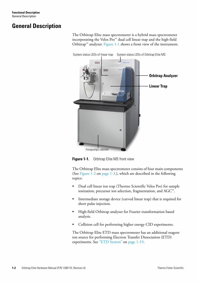
General DescriptionThe Orbitrap Elite mass spectrometer is a hybrid mass spectrometer incorporating the Velos Pro™ dual cell linear trap and the high-field Orbitrap™ analyzer. Figure 1-1 shows a front view of the instrument.
The Orbitrap Elite mass spectrometer consists of four main components (See Figure 1-2 on page 1-3.), which are described in the following topics:
• Dual cell linear ion trap (Thermo Scientific Velos Pro) for sample ionization, precursor ion selection, fragmentation, and AGC™.
• Intermediate storage device (curved linear trap) that is required for short pulse injection.
• High-field Orbitrap analyzer for Fourier transformation based analysis.
• Collision cell for performing higher energy CID experiments.
The Orbitrap Elite ETD mass spectrometer has an additional reagent ion source for performing Electron Transfer Dissociation (ETD) experiments. See “ETD System” on page 1-19.
Figure 1-1. Orbitrap Elite MS front view
Linear Trap
Orbitrap Analyzer
Forepumps cabinet
System status LEDs of Orbitrap Elite MSSystem status LEDs of linear trap

Functional DescriptionGeneral Description
Thermo Fisher Scientific Orbitrap Elite Hardware Manual (P/N 1288170, Revision A) 1-3
Mechanical Characteristics
Wheels at the bottom side of the instrument facilitate positioning the Orbitrap Elite mass spectrometer at the intended place in the laboratory.
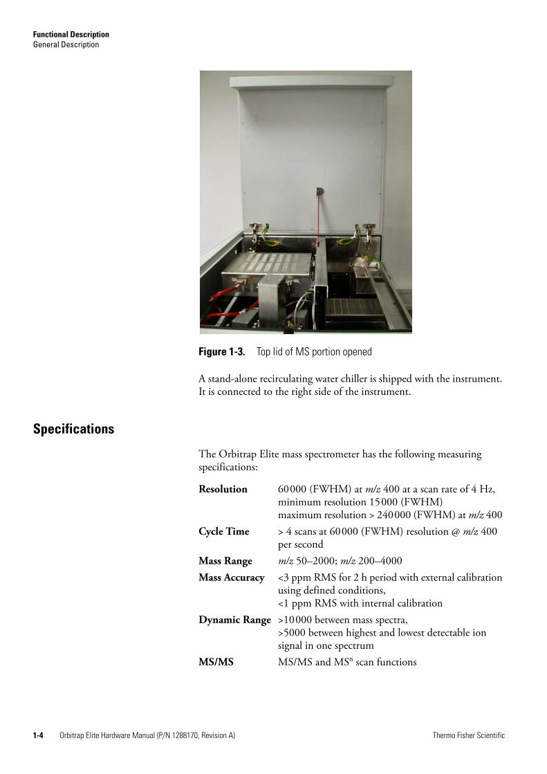
The mains inlet as well as a power outlet for peripheral devices are located at the right side of the instrument. The forepumps for the vacuum system of the linear trap and the Orbitrap analyzer are hidden under the linear trap and accessible from the front. The forepump for the ETD Module is accessible after removing the bottom panel of the rear side. The left side panel and the front panel of the MS portion are mounted on hinges and the right side panel is removable. The top lid of the MS portion opens upwards to allow easy access for Thermo Fisher Scientific field service engineers from the top. See Figure 1-3.
In the Orbitrap Elite ETD mass spectrometer, after removing the cables the top lid of the ETD Module is also removable to allow accessing its electronic components.
Figure 1-2. Schematic of the Orbitrap Elite MS
Electrospray Ion Source High Pressure Cell C-Trap HCD Cell
Velos Pro MS Orbitrap analyzerS-Lens Low Pressure CellOctopole Multipole
High-field Orbitrap Mass Analyzer
Square Quadrupolewith neutral blocking
Functional DescriptionGeneral Description
1-4 Orbitrap Elite Hardware Manual (P/N 1288170, Revision A) Thermo Fisher Scientific
A stand-alone recirculating water chiller is shipped with the instrument. It is connected to the right side of the instrument.
Specifications
The Orbitrap Elite mass spectrometer has the following measuring specifications:
Figure 1-3. Top lid of MS portion opened
Resolution 60000 (FWHM) at m/z 400 at a scan rate of 4 Hz,minimum resolution 15000 (FWHM)maximum resolution > 240000 (FWHM) at m/z 400
Cycle Time > 4 scans at 60000 (FWHM) resolution @ m/z 400 per second
Mass Range m/z 50–2000; m/z 200–4000Mass Accuracy <3 ppm RMS for 2 h period with external calibration
using defined conditions,<1 ppm RMS with internal calibration
Dynamic Range >10000 between mass spectra,>5000 between highest and lowest detectable ion signal in one spectrum
MS/MS MS/MS and MSn scan functions

Functional DescriptionControl Elements
Thermo Fisher Scientific Orbitrap Elite Hardware Manual (P/N 1288170, Revision A) 1-5
Control ElementsThe Orbitrap Elite mass spectrometer is mainly operated from the desktop computer (data system). Some control elements for important system functions are located directly on the instrument. They are described in the following sections.
System Status LEDs
Figure 1-4 shows the system status LEDs at the front of the instrument. Five LEDs indicate the main functions of the system. (See also Figure 1-5 on page 1-6.) The Power LED is directly controlled by the 3 × 230 V input and all other LEDs are controlled by the power distribution board (See “Power Distribution Board” on page 1-53). Table 1-1 explains the function of the various LEDs.
The system status LEDs at the front panel of the linear ion trap are described in the LTQ Series Hardware Manual.
Figure 1-4. System status LEDs
Table 1-1. System status LEDs of the Orbitrap Elite MS
LED Status Information
Power Green
Off
Main switch on
Main switch off
Vacuuma
a These LEDs are flashing when a system bakeout is performed. See “Baking Out the System” onpage 3-4.
Green
Yellow
Operating vacuum reached
Insufficient vacuum or Vacuum Pumps switch off
Communication Green
Yellow
Communication link between instrument and data system established
Communication link starting up or Vacuum Pumps switch off
Systema Green
Yellow
System ready
FT Electronics switch off or Vacuum Pumps switch off
Detect Blue
Off
Orbitrap analyzer is scanning
Orbitrap analyzer is not scanning
Functional DescriptionControl Elements
1-6 Orbitrap Elite Hardware Manual (P/N 1288170, Revision A) Thermo Fisher Scientific
Control Panels
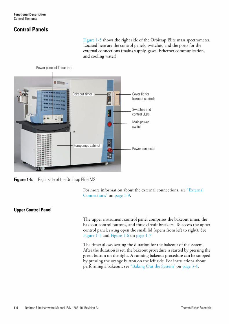
Figure 1-5 shows the right side of the Orbitrap Elite mass spectrometer. Located here are the control panels, switches, and the ports for the external connections (mains supply, gases, Ethernet communication, and cooling water).
For more information about the external connections, see “External Connections” on page 1-9.
Upper Control Panel
The upper instrument control panel comprises the bakeout timer, the bakeout control buttons, and three circuit breakers. To access the upper control panel, swing open the small lid (opens from left to right). See Figure 1-5 and Figure 1-6 on page 1-7.
The timer allows setting the duration for the bakeout of the system. After the duration is set, the bakeout procedure is started by pressing the green button on the right. A running bakeout procedure can be stopped by pressing the orange button on the left side. For instructions about performing a bakeout, see “Baking Out the System” on page 3-4.
Figure 1-5. Right side of the Orbitrap Elite MS
Bakeout timer
Power connector
Power panel of linear trap
Main power switch
Switches and control LEDs
Cover lid for bakeout controls
Forepumps cabinet
Functional DescriptionControl Elements
Thermo Fisher Scientific Orbitrap Elite Hardware Manual (P/N 1288170, Revision A) 1-7
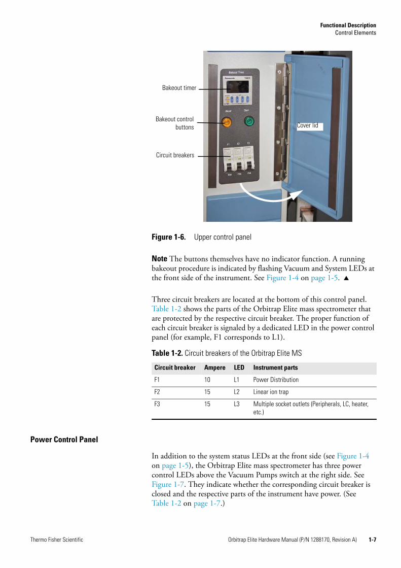
Note The buttons themselves have no indicator function. A running bakeout procedure is indicated by flashing Vacuum and System LEDs at the front side of the instrument. See Figure 1-4 on page 1-5.
Three circuit breakers are located at the bottom of this control panel. Table 1-2 shows the parts of the Orbitrap Elite mass spectrometer that are protected by the respective circuit breaker. The proper function of each circuit breaker is signaled by a dedicated LED in the power control panel (for example, F1 corresponds to L1).
Power Control Panel
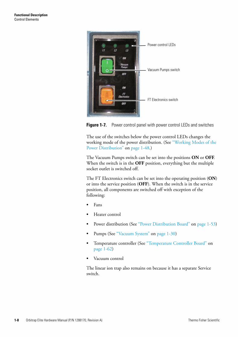
In addition to the system status LEDs at the front side (see Figure 1-4 on page 1-5), the Orbitrap Elite mass spectrometer has three power control LEDs above the Vacuum Pumps switch at the right side. See Figure 1-7. They indicate whether the corresponding circuit breaker is closed and the respective parts of the instrument have power. (See Table 1-2 on page 1-7.)
Figure 1-6. Upper control panel
Table 1-2. Circuit breakers of the Orbitrap Elite MS
Circuit breaker Ampere LED Instrument parts
F1 10 L1 Power Distribution
F2 15 L2 Linear ion trap
F3 15 L3 Multiple socket outlets (Peripherals, LC, heater, etc.)
Circuit breakers
Bakeout controlbuttons
Bakeout timer
Cover lid
Functional DescriptionControl Elements
1-8 Orbitrap Elite Hardware Manual (P/N 1288170, Revision A) Thermo Fisher Scientific
The use of the switches below the power control LEDs changes the working mode of the power distribution. (See “Working Modes of the Power Distribution” on page 1-48.)
The Vacuum Pumps switch can be set into the positions ON or OFF. When the switch is in the OFF position, everything but the multiple socket outlet is switched off.
The FT Electronics switch can be set into the operating position (ON) or into the service position (OFF). When the switch is in the service position, all components are switched off with exception of the following:
• Fans
• Heater control
• Power distribution (See “Power Distribution Board” on page 1-53)
• Pumps (See “Vacuum System” on page 1-30)
• Temperature controller (See “Temperature Controller Board” on page 1-62)
• Vacuum control
The linear ion trap also remains on because it has a separate Service switch.
Figure 1-7. Power control panel with power control LEDs and switches
Power control LEDs
Vacuum Pumps switch
FT Electronics switch

Functional DescriptionControl Elements
Thermo Fisher Scientific Orbitrap Elite Hardware Manual (P/N 1288170, Revision A) 1-9
Main Power Switch
The main power switch must be turned 90° clockwise/anti-clockwise to switch on/off the instrument (see Figure 1-8). Placing the main power switch in the Off position turns off all power to the Orbitrap Elite mass spectrometer, the linear ion trap, and the vacuum pumps. In the Orbitrap Elite ETD mass spectrometer, power to the ETD Module is also turned off.
Note When the main power switch is in the Off position, you can secure it with a padlock or a cable tie (to prevent unintended re-powering when performing maintenance, for example).
External Connections
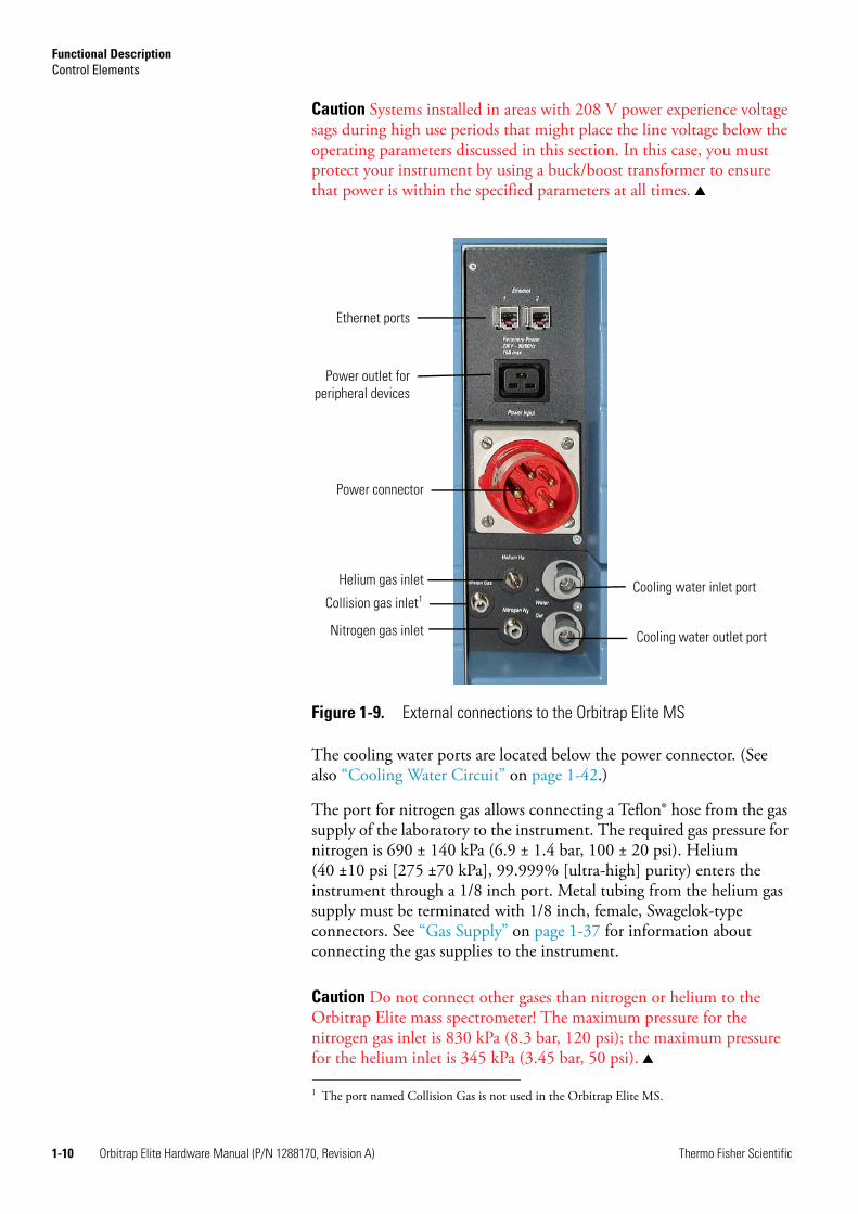
Figure 1-9 on page 1-10 shows the lower right side of the instrument with the external connections for mains supply, gases, cooling water, and Ethernet communication.
Located at the top are two ports for Ethernet cables for connecting the Orbitrap Elite mass spectrometer and the linear ion trap via an Ethernet hub with the data system computer.
The power outlet for peripheral devices is located below the Ethernet ports. In the Orbitrap Elite mass spectrometer, the outlet provides the mains supply for the data system. In the Orbitrap Elite ETD mass spectrometer, the outlet provides the mains supply for the ETD Module whereas the data system is connected to a wall outlet.
The power connector for the mains supply is located at the center. The Orbitrap Elite mass spectrometer is designed to operate at a nominal voltage of 230 V AC, 50/60 Hz. Line voltages can vary between a minimum of 207 V AC and a maximum of 253 V AC.
Figure 1-8. Main power switch
On
Off
Functional DescriptionControl Elements
1-10 Orbitrap Elite Hardware Manual (P/N 1288170, Revision A) Thermo Fisher Scientific
Caution Systems installed in areas with 208 V power experience voltage sags during high use periods that might place the line voltage below the operating parameters discussed in this section. In this case, you must protect your instrument by using a buck/boost transformer to ensure that power is within the specified parameters at all times.
1
The cooling water ports are located below the power connector. (See also “Cooling Water Circuit” on page 1-42.)
The port for nitrogen gas allows connecting a Teflon® hose from the gas supply of the laboratory to the instrument. The required gas pressure for nitrogen is 690 ± 140 kPa (6.9 ± 1.4 bar, 100 ± 20 psi). Helium (40 ±10 psi [275 ±70 kPa], 99.999% [ultra-high] purity) enters the instrument through a 1/8 inch port. Metal tubing from the helium gas supply must be terminated with 1/8 inch, female, Swagelok-type connectors. See “Gas Supply” on page 1-37 for information about connecting the gas supplies to the instrument.
Caution Do not connect other gases than nitrogen or helium to the Orbitrap Elite mass spectrometer! The maximum pressure for the nitrogen gas inlet is 830 kPa (8.3 bar, 120 psi); the maximum pressure for the helium inlet is 345 kPa (3.45 bar, 50 psi).
Figure 1-9. External connections to the Orbitrap Elite MS
1 The port named Collision Gas is not used in the Orbitrap Elite MS.
Power connector
Helium gas inlet
Nitrogen gas inlet
Ethernet ports
Cooling water inlet port
Power outlet forperipheral devices
Cooling water outlet port
Collision gas inlet1

Functional DescriptionControl Elements
Thermo Fisher Scientific Orbitrap Elite Hardware Manual (P/N 1288170, Revision A) 1-11
In the Orbitrap Elite ETD mass spectrometer, the ETD reagent carrier gas supply of the laboratory is connected via metal tubing to an1/8 inch inlet port at the rear side of the instrument. Metal tubing from the gas supply must be terminated with 1/8 inch, female, Swagelok-type connectors. The required gas pressure is 690 ± 140 kPa (6.9 ± 1.4 bar, 100 ± 20 psi). See “Gas Supply of the Reagent Ion Source” on page 1-40.
The exhaust hose from the rotary pumps comes out the back of the instrument, and connects the pumps to the exhaust system in the laboratory.
Functional DescriptionLinear Ion Trap
1-12 Orbitrap Elite Hardware Manual (P/N 1288170, Revision A) Thermo Fisher Scientific
Linear Ion TrapThe Orbitrap Elite system can utilize a variety of ionization techniques such as ESI, APCI, or APPI. Maintenance of the Ion Max API source, as well as switching between ionization methods, is vent-free. Ions are transferred by octapole and “square” quadrupole lenses into an ion trap that is optimized for axial ion ejection into the curved linear trap. (See Figure 1-2 on page 1-3.)
The linear ion trap is an independent MS detector (Thermo Scientific Velos Pro), which can store, isolate, and fragment ions and then send them either to the Orbitrap analyzer for further analysis or to an SEM detector. The linear ion trap is a unique ion preparation and injection system for Orbitrap MS, because it has greater ion storage capacity than conventional 3D ion trap devices. The linear ion trap is completely described in the LTQ Series Hardware Manual.
All the ion handling, selection and excitation capabilities of the ion trap can be used to prepare ions for analysis in the Orbitrap analyzer. These features include storage and ejection of all ions, storage of selected m/z ranges, as well as ion isolation. Isolated ions can be excited and then fragmented as necessary for MS/MS and MSn experiments. The patented Automatic Gain Control (AGC) provides extended dynamic range and insures optimized overall performance of the ion trap and Orbitrap MS.
The application of a supplementary RF voltage on the end lenses of the linear trap allows ions of opposite polarity to be trapped in the same space at the same time (charge-sign independent trapping—CSIT). This allows performing ion-ion reactions of previously isolated precursor cations with ETD reagent anions.
The linear ion trap and the transfer chamber are mounted on a table. See Figure 1-1 on page 1-2. The table also serves as a housing for the forepumps. See Figure 1-26 on page 1-33. The Orbitrap Elite mass spectrometer provides power for the linear ion trap. The Orbitrap Elite ETD mass spectrometer also provides the power for the ETD Module.
The linear ion trap is delivered with power connector, gas lines (He, N2), and vacuum tube lines extending to the ESI source. On the rear side of the Velos Pro ion trap is a flange with an O-ring seal. When the flange is removed, the Orbitrap transfer chamber is mounted to the flange of the linear ion trap. The transfer chamber is held with supports on the table. The components of the ion optics and the Orbitrap analyzer are fixed to the transfer chamber.

Functional DescriptionCurved Linear Trap
Thermo Fisher Scientific Orbitrap Elite Hardware Manual (P/N 1288170, Revision A) 1-13
Curved Linear TrapOn their way from the linear trap to the Orbitrap analyzer, ions move through the gas-free RF-only octapole into the gas-filled curved linear trap (C-Trap). See Figure 1-10. Ions entering the C-Trap loose their kinetic energy in collisions with nitrogen bath gas emanating from the HCD cell and get collected near the middle part of the C-Trap. The nitrogen collision gas (bath gas) is used for dissipating the kinetic energy of injected ions to cool them down to the axis of the C-Trap.
Voltages on the end apertures of the curved trap (entrance and exit apertures) are elevated to provide a potential well along its axis. These voltages may be later ramped up to squeeze ions into a smaller package along this axis. The RF to the C-Trap (“Main RF”) is provided by the CLT RF main board. (See page 1-63.) Entrance and exit DC voltages as well as RF voltages to the transfer multipole are all provided by the ion optic supply board. (See page 1-59.) High voltages to the lenses are provided by the high voltage power supply board. (See page 1-66.)
Figure 1-10. Layout of the Orbitrap Elite MS, also showing the applied voltages
Multipole Collision Cell
Static
Pulsing from Velos Pro
Squeezing in C-Trap
Entrance C-Trap Exit

Functional DescriptionOrbitrap Analyzer
1-14 Orbitrap Elite Hardware Manual (P/N 1288170, Revision A) Thermo Fisher Scientific
Orbitrap AnalyzerThe heart of the Orbitrap™ analyzer is an axially-symmetrical mass analyzer. It consists of a spindle-shape central electrode surrounded by a pair of bell-shaped outer electrodes. See Figure 1-11. The Orbitrap analyzer employs electric fields to capture and confine ions.
Extraction of Ion Packets
For ion extraction, the RF on the rods of the C-Trap is ramped off and extracting voltage pulses are applied to the electrodes, pushing ions orthogonally to the curved axis through a slot in the inner electrode. Because of the initial curvature of the C-Trap and the subsequent lenses, the ion beam converges on the entrance into the Orbitrap analyzer. The lenses that follow the C-Trap (Z-lens) form also differential pumping slots and cause spatial focusing of the ion beam into the entrance of the Orbitrap analyzer. Ions are electrostatically deflected away from the gas jet, thereby eliminating gas carryover into the Orbitrap analyzer.
Owing to the fast pulsing of ions from the C-Trap, ions of each mass-to-charge ratio arrive at the entrance of the Orbitrap analyzer as short packets only a few millimeters long. For each mass-to-charge population, this corresponds to a spread of flight times of only a few hundred nanoseconds for mass-to-charge ratios of a few hundred Daltons/charge. Such durations are considerably shorter than a half-period of axial ion oscillation in the trap. When ions are injected into the Orbitrap analyzer at a position offset from its equator (See Figure 1-12.), these packets start coherent axial oscillations without the need for any additional excitation cycle.
Figure 1-11. Schematic of Orbitrap cell and example of stable ion trajectory
r
z
Functional DescriptionOrbitrap Analyzer
Thermo Fisher Scientific Orbitrap Elite Hardware Manual (P/N 1288170, Revision A) 1-15
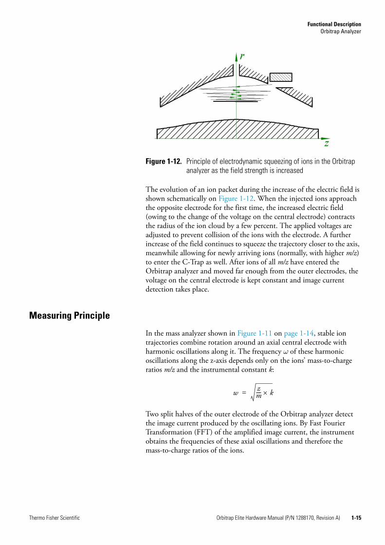
The evolution of an ion packet during the increase of the electric field is shown schematically on Figure 1-12. When the injected ions approach the opposite electrode for the first time, the increased electric field (owing to the change of the voltage on the central electrode) contracts the radius of the ion cloud by a few percent. The applied voltages are adjusted to prevent collision of the ions with the electrode. A further increase of the field continues to squeeze the trajectory closer to the axis, meanwhile allowing for newly arriving ions (normally, with higher m/z) to enter the C-Trap as well. After ions of all m/z have entered the Orbitrap analyzer and moved far enough from the outer electrodes, the voltage on the central electrode is kept constant and image current detection takes place.
Measuring Principle
In the mass analyzer shown in Figure 1-11 on page 1-14, stable ion trajectories combine rotation around an axial central electrode with harmonic oscillations along it. The frequency ω of these harmonic oscillations along the z-axis depends only on the ions’ mass-to-charge ratios m/z and the instrumental constant k:
Two split halves of the outer electrode of the Orbitrap analyzer detect the image current produced by the oscillating ions. By Fast Fourier Transformation (FFT) of the amplified image current, the instrument obtains the frequencies of these axial oscillations and therefore the mass-to-charge ratios of the ions.
Figure 1-12. Principle of electrodynamic squeezing of ions in the Orbitrap analyzer as the field strength is increased
w zm---- k×=
Functional DescriptionOrbitrap Analyzer
1-16 Orbitrap Elite Hardware Manual (P/N 1288170, Revision A) Thermo Fisher Scientific
Ion Detection
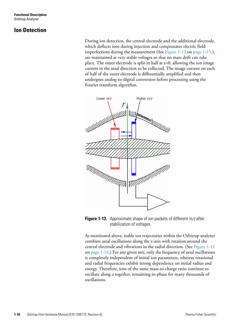
During ion detection, the central electrode and the additional electrode, which deflects ions during injection and compensates electric field imperfections during the measurement (See Figure 1-12 on page 1-15.), are maintained at very stable voltages so that no mass drift can take place. The outer electrode is split in half at z=0, allowing the ion image current in the axial direction to be collected. The image current on each of half of the outer electrode is differentially amplified and then undergoes analog-to-digital conversion before processing using the Fourier transform algorithm.
As mentioned above, stable ion trajectories within the Orbitrap analyzer combine axial oscillations along the z-axis with rotation around the central electrode and vibrations in the radial direction. (See Figure 1-11 on page 1-14.) For any given m/z, only the frequency of axial oscillations is completely independent of initial ion parameters, whereas rotational and radial frequencies exhibit strong dependence on initial radius and energy. Therefore, ions of the same mass-to-charge ratio continue to oscillate along z together, remaining in-phase for many thousands of oscillations.
Figure 1-13. Approximate shape of ion packets of different m/z after stabilization of voltages
Lower m/z Higher m/z

Functional DescriptionOrbitrap Analyzer
Thermo Fisher Scientific Orbitrap Elite Hardware Manual (P/N 1288170, Revision A) 1-17
In contrast to the axial oscillations, the frequencies of radial and rotational motion will vary for ions with slightly different initial parameters. This means that in the radial direction, ions dephase orders of magnitude faster than in the axial direction, and the process occurs in a period of only 50–100 oscillations. After this, the ion packet of a given m/z assumes the shape of a thin ring, with ions uniformly distributed along its circumference. (See Figure 1-13.) Because of this angular and radial smearing, radial and rotational frequencies cannot appear in the measured spectrum. Meanwhile, axial oscillations will persist, with axial thickness of the ion ring remaining small compared with the axial amplitude. Moving from one half outer electrode to the other, this ring will induce opposite currents on these halves, thus creating a signal to be detected by differential amplification.
Active Temperature Control
Active temperature control is achieved by monitoring temperature directly on the Orbitrap analyzer assembly and compensating any changes in ambient temperature by a thermoelectric cooler (Peltier element) on the outside of the UHV chamber. A dedicated temperature controller board is used for this purpose. See page 1-62.
Peltier Cooling
To allow stable operating conditions in the UHV chamber, it can be cooled or heated (outgassing) by means of a Peltier element located on the outside. A second Peltier element is located on the back of the CE power supply board. See Figure 1-43 on page 1-59.
The Peltier cooling is based on the Peltier Effect, which describes the effect by which the passage of an electric current through a junction of two dissimilar materials (thermoelectric materials) causes temperature differential (cooling effect). The voltage drives the heat to flow from one side of the Peltier element to the other side, resulting in cooling effects on one side and heating effects on the other side.
To remove the heat from the hot side of the Peltier elements, they are connected to the cooling water circuit of the Orbitrap Elite mass spectrometer. See “Cooling Water Circuit” on page 1-42 for further information.
Functional DescriptionHCD Cell
1-18 Orbitrap Elite Hardware Manual (P/N 1288170, Revision A) Thermo Fisher Scientific
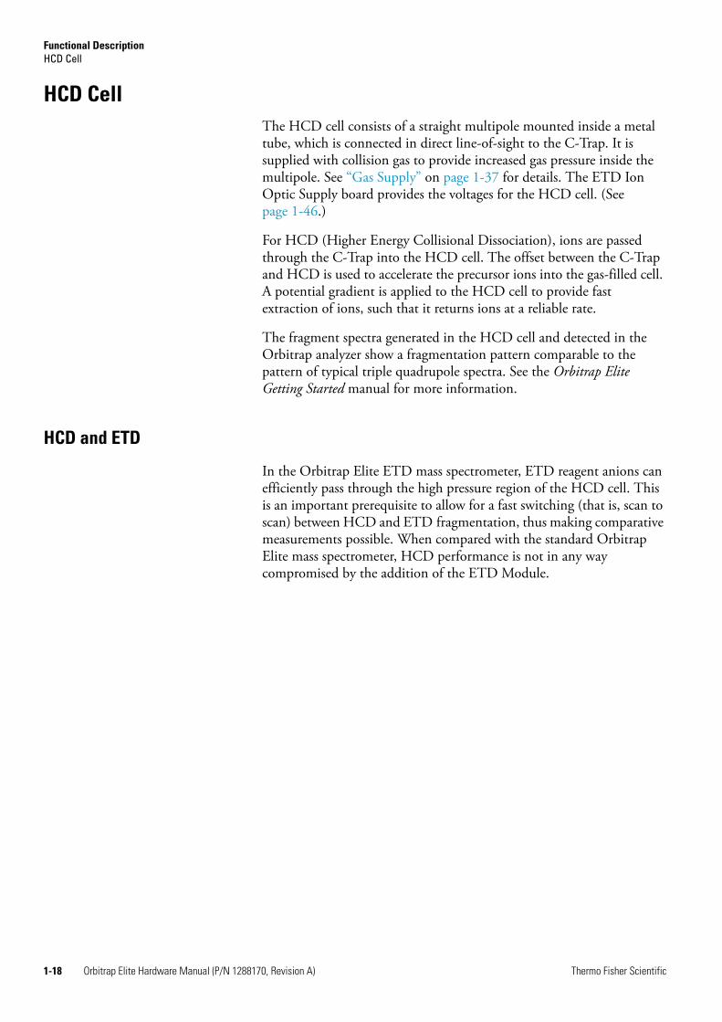
HCD CellThe HCD cell consists of a straight multipole mounted inside a metal tube, which is connected in direct line-of-sight to the C-Trap. It is supplied with collision gas to provide increased gas pressure inside the multipole. See “Gas Supply” on page 1-37 for details. The ETD Ion Optic Supply board provides the voltages for the HCD cell. (See page 1-46.)
For HCD (Higher Energy Collisional Dissociation), ions are passed through the C-Trap into the HCD cell. The offset between the C-Trap and HCD is used to accelerate the precursor ions into the gas-filled cell. A potential gradient is applied to the HCD cell to provide fast extraction of ions, such that it returns ions at a reliable rate.
The fragment spectra generated in the HCD cell and detected in the Orbitrap analyzer show a fragmentation pattern comparable to the pattern of typical triple quadrupole spectra. See the Orbitrap Elite Getting Started manual for more information.
HCD and ETD
In the Orbitrap Elite ETD mass spectrometer, ETD reagent anions can efficiently pass through the high pressure region of the HCD cell. This is an important prerequisite to allow for a fast switching (that is, scan to scan) between HCD and ETD fragmentation, thus making comparative measurements possible. When compared with the standard Orbitrap Elite mass spectrometer, HCD performance is not in any way compromised by the addition of the ETD Module.

Functional DescriptionETD System
Thermo Fisher Scientific Orbitrap Elite Hardware Manual (P/N 1288170, Revision A) 1-19
ETD SystemIn the Orbitrap Elite ETD mass spectrometer, an ETD Module is physically coupled to the back of the Orbitrap Elite mass spectrometer. See Figure 1-14. A quadrupole mass filter replaces the octapole of the Orbitrap Elite MS. See Figure 1-2 on page 1-3. The linear trap provides the voltages for the quadrupole mass filter. A tube, which contains the transfer multipole, connects the HCD housing to the ETD Module. See Figure 1-23 on page 1-30. The ETD Ion Optic Supply board is mounted on top of the data acquisition unit on the right side of the instrument. See Figure 1-35 on page 1-47.
Protein or peptide analyte ions may also be fragmented in the linear trap by negatively charged reagent ions (fluoranthene radical anions) from the reagent ion source (ETD Module). These negatively charged ions transfer electrons to protein or peptide analyte ions and cause them to fragment at their peptide bonds to produce c and z type fragments (versus the y and b fragments produced by CID). The resulting analyte fragment ions provide another way of analyzing these molecules as compared to CID and PQD. Electron Transfer Dissociation (ETD) improves the identification of important post-translational modification (PTM) for characterization.
Note Among others, the ETD system is also available as an upgrade on existing Velos Pro and Orbitrap Elite systems.
Figure 1-14. Orbitrap Elite ETD MS front view
Linear Trap
ETD Module
Orbitrap Analyzer
1-20 Orbitrap Elite Hardware Manual (P/N 1288170, Revision A) Thermo Fisher Scientific
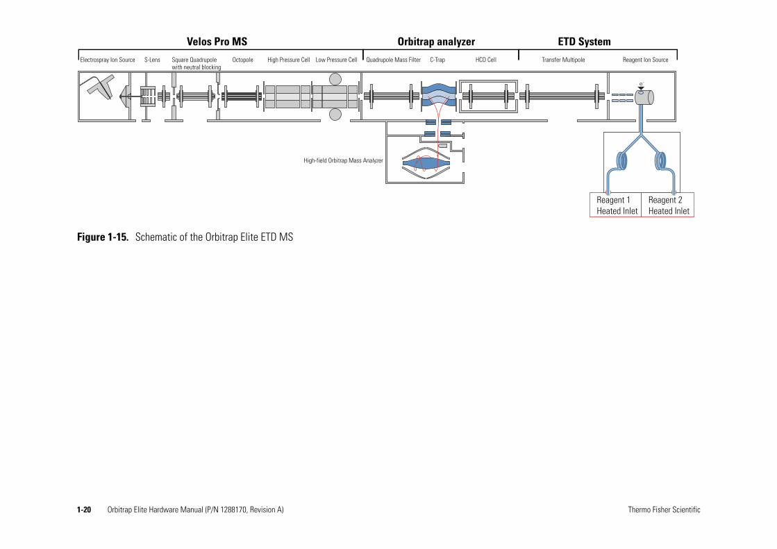
Figure 1-15. Schematic of the Orbitrap Elite ETD MS
e-
Electrospray Ion Source High Pressure Cell C-Trap Transfer Multipole Reagent Ion Source
High-field Orbitrap Mass Analyzer
Quadrupole Mass Filter HCD Cell
Velos Pro MS Orbitrap analyzer ETD SystemS-Lens Low Pressure CellSquare Quadrupole
with neutral blockingOctopole
Reagent 1 Heated Inlet
Reagent 2 Heated Inlet

Functional DescriptionETD System
Thermo Fisher Scientific Orbitrap Elite Hardware Manual (P/N 1288170, Revision A) 1-21
Principle of Operation
During a typical ETD MS/MS scan, analyte cations are injected into the linear trap for subsequent precursor cation isolation. Then, ETD reagent anions are generated in the CI ion source and are transferred into the linear trap via RF-only ion guides (transfer multipoles), the gas-filled HCD cell, and the C-Trap. (See Figure 1-15 on page 1-20.)
The reagent ions pass a quadrupole mass filter between C-Trap and linear trap. This ion guide works as a low pass mass filter to remove the adduct ions of the fluoranthene radicals and molecular nitrogen at m/z 216. These adduct ions favor proton transfer reactions instead of electron transfer.
The application of a supplementary RF voltage on the end lenses of the linear trap allows ions of opposite polarity to be trapped in the same space at the same time (charge-sign independent trapping—CSIT).
During ion-ion reactions in the linear trap, electrons are transferred from the reagent anions to the precursor cations. The resulting product ions are mass-to-charge (m/z) analyzed in either the linear trap (if speed and sensitivity are important) or the Orbitrap analyzer (if mass resolution and mass accuracy are important).
ETD Module
Figure 1-16 on page 1-22 shows the rear side of the ETD Module. It consists of the reagent ion source, ETD Module electronics, ETD Module power supply, ETD Module forepump, and the hardware that connects the ETD Module to the mass detectors.
Functional DescriptionETD System
1-22 Orbitrap Elite Hardware Manual (P/N 1288170, Revision A) Thermo Fisher Scientific
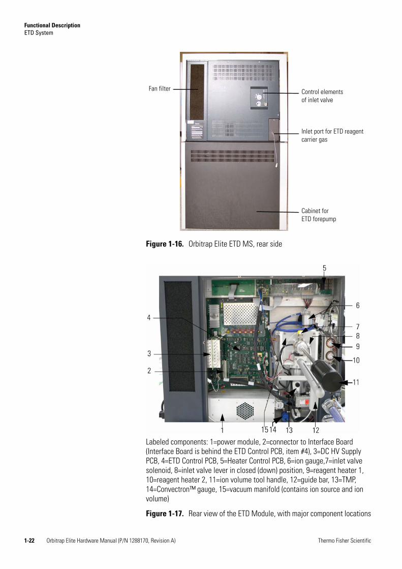
Figure 1-16. Orbitrap Elite ETD MS, rear side
Labeled components: 1=power module, 2=connector to Interface Board (Interface Board is behind the ETD Control PCB, item #4), 3=DC HV Supply PCB, 4=ETD Control PCB, 5=Heater Control PCB, 6=ion gauge,7=inlet valve solenoid, 8=inlet valve lever in closed (down) position, 9=reagent heater 1, 10=reagent heater 2, 11=ion volume tool handle, 12=guide bar, 13=TMP, 14=Convectron™ gauge, 15=vacuum manifold (contains ion source and ion volume)
Figure 1-17. Rear view of the ETD Module, with major component locations
Control elements of inlet valve
Cabinet for ETD forepump
Inlet port for ETD reagent carrier gas
Fan filter
1415

Functional DescriptionETD System
Thermo Fisher Scientific Orbitrap Elite Hardware Manual (P/N 1288170, Revision A) 1-23
The following sections describe the major ETD Module components that are shown in Figure 1-17 on page 1-22 and Figure 1-18.
ETD Power Module
The ETD power module (item #1 in Figure 1-17) receives 220 V, 10 A, from the peripherals power outlet. See Figure 1-9 on page 1-10. It distributes appropriate voltages and currents to the ETD components. It also contains DC power supplies.
ETD Module Power Panel
The external receptacles and switches for the power module are located on the ETD power module panel at the right side of the ETD Module. See Figure 1-19.
Figure 1-18. ETD Module functional block diagram
H1
H2
3
4
ETD Forepump
Interface Board
ETD Control PCB
DC HV Supply PCB
Ion Source
ETD TMP
Convectron Gauge
Reagent Heaters
Flow Control
ETD Reagent Carrier Gas
3 = Transfer line4 = Ion volume
Peripherals Power Outlet Orbitrap Analyzer
Instrument Control Board
ETD Ion Optic Supply Board
Heater Control PCB
Orbitrap Vacuum System, see Figure 1-23 on page 1-30
Ion GaugePower Module
Orbitrap EliteETD Module

Functional DescriptionETD System
1-24 Orbitrap Elite Hardware Manual (P/N 1288170, Revision A) Thermo Fisher Scientific
Figure 1-20 shows a close up picture of the ETD Power Module panel. Power In is connected to the peripherals power outlet of the MS portion. See Figure 1-9 on page 1-10. Forepump is a receptacle to power the ETD forepump (220 V AC, 5 A).
Figure 1-19. Right side of the Orbitrap Elite ETD MS
ETD Module power panel
ETD Module
Figure 1-20. ETD Power Module panel
ETD Module Service switch
ETD Module Power switch
ETD Module Forepump receptacle
ETD Module Power receptacle
ETD Module Power Panel

Functional DescriptionETD System
Thermo Fisher Scientific Orbitrap Elite Hardware Manual (P/N 1288170, Revision A) 1-25
The ETD power module panel contains the main breaker and the service switch for the ETD Module. During normal operation, the ETD Power switch is left On and the service switch is left in the Operating Mode position. As a safety feature, both components of the Orbitrap Elite ETD system (the mass spectrometer and the ETD Module) are shut down with one set of switches, the mass spectrometer switches. When you perform maintenance on components inside the ETD Module as described in “Maintenance of the ETD Module” on page 3-12, you set the mass spectrometer’s service switch to the Service position. The service switch turns On or Off power to all ETD Module components except turbomolecular pump and forepump.
ETD Module Interface Board
The ETD Module Interface board (item #2 in Figure 1-17 on page 1-22) provides an electronic interface between the ETD Module and the MS. This board also allows the power to both the MS and the ETD Module to be controlled by the MS power control panel switches:
• The MS Main Power switch controls the power supply to all components in both the MS and the ETD Module.
• The MS FT Electronics switch controls the power supply to all mass spectrometer and ETD Module components except the pumps that are connected to the MS and the ETD Module.
Note The ability to control the power to both components of the Orbitrap Elite ETD mass spectrometer at one point (the power control panel switches of the MS) is a safety feature.
ETD Control PCB
The ETD Control PCB (item #4 in Figure 1-17) controls most of the ETD Module functions. The ETD Control PCB consists of circuits that control:
• ETD Module operating logic
• Ion source (filament, ion source heater, lenses)
• Heater temperature and readback logic (for reagent heaters, transfer line heater, and the restrictor oven heater)
• Reagent gas flow
• Oven cooling gas control
• Ion gauge
• Convectron™ gauge
Functional DescriptionETD System
1-26 Orbitrap Elite Hardware Manual (P/N 1288170, Revision A) Thermo Fisher Scientific
The DC HV Supply PCB (item #3 in Figure 1-17 on page 1-22) is plugged in to the ETD Control PCB.
ETD Heater Control PCB
The ETD Module Heater Control PCB (item #6 in Figure 1-17) contains the power source and temperature sensing circuitry for the four heaters in the reagent ion source. The heaters are H1 and H2 (the two reagent heaters, Figure 1-18 on page 1-23, and items #9 and #10 in Figure 1-17), the transfer line heater (#3 in Figure 1-17), and the restrictor oven heater (not shown in Figure 1-17). The Heater Control PCB reports temperature information to the heater temperature and readback logic on the ETD Control PCB. The heater temperature and readback logic controls how the Heater Control PCB applies power to the ETD Module heaters.
Reagent Carrier Gas Flow Control for ETD
The ETD Module contains a digital flow control for the chemical ionization (CI) gas/reagent carrier gas provided by the ETD Control PCB (See Figure 1-17 on page 1-22.) and an electronic pressure regulator. The gas serves two functions in the ETD Module:
• As a carrier gas, the nitrogen sweeps the reagent (fluoranthene) from the vial to the ion source where the reagent radical anions are formed.
• As a chemical ionization (CI) vehicle, the nitrogen undergoes collisions with 70 eV electrons from the filament in the ion volume. These 70 eV electrons from the filament knock electrons off of the nitrogen molecules (nitrogen ions are created). The secondary electrons resulting from these collisions have near thermal kinetic energies. These thermal electrons are captured by the fluoranthene to form reagent radical anions that react with the analyte.
Thermo Fisher Scientific strongly recommends a mixture of 25% helium and 75% nitrogen. The helium in this mixture serves as a tracer gas to enable leak checking of gas connections using conventional thermal conductivity-based leak detectors, which are widely used to check leaks in gas chromatography equipment. See “Gas Supply of the Reagent Ion Source” on page 1-40 for detailed information.
The reagent carrier gas supply in the laboratory is connected to the ETD reagent carrier gas port at the rear side of the ETD Module. See Figure 1-31 on page 1-40.

Functional DescriptionETD System
Thermo Fisher Scientific Orbitrap Elite Hardware Manual (P/N 1288170, Revision A) 1-27
Reagent Heaters
The reagent heaters (items #9 and #10 in Figure 1-17 on page 1-22, H1 and H2 in Figure 1-18 on page 1-23) heat the reagent to obtain a sufficient amount of reagent vapor in the carrier gas. The reagent heaters are powered by the Heater Control PCB which, in turn, is controlled by the ETD Control PCB.
The reagent heaters are turned on by selecting the Reagent Ion Source On check box in the Reagent Ion Source dialog box. See Figure 1-21.
When you deselect the Reagent Ion Source On check box, the reagent heaters and filament immediately turn off and the reagent ion source goes into Standby mode.
When the reagent ion source is placed in Off mode, cooling nitrogen (high-purity nitrogen) will turn on. This is confirmed by an audible rush (hissing noise) of nitrogen from the reagent ion source area in the back of the ETD Module. This is normal operation. See also “Turning Off the Reagent Ion Source: What to Expect” on page 2-14.
Figure 1-21. Reagent Ion Source dialog box
Warning Burn Hazard. When the reagent ion source is in Off mode, restrictor oven, transfer line, and ion source remain at 160 °C.

Functional DescriptionETD System
1-28 Orbitrap Elite Hardware Manual (P/N 1288170, Revision A) Thermo Fisher Scientific
The nitrogen cooling gas turns off when the reagent heaters reach 70 °C. If it is necessary to install or replace the reagent vials, follow the procedure in “Replacing the Reagent Vials” on page 3-48.
Note The rushing or hissing noise of the nitrogen coming from the back of the ETD Module will stop when the cooling nitrogen turns off.
When the reagent heaters are in Standby mode, they are immediately turned on by selecting the Reagent Ion Source On check box (Figure 1-21 on page 1-27). When starting from room temperature, it takes up to ten minutes for the reagent heaters and vials to stabilize at 108 °C and reagent to delivered to the ion source.
Note When you switch on a cold reagent ion source, the Tune Plus software warns you that the vial temperature is not sufficient. The filament is automatically switched on after the temperature has stabilized.
When you click the Standby button in the Tune Plus window (shown in the left margin), you initiate a Standby process. It delays turning off the reagent heaters and the start of nitrogen cooling for one hour after the system is placed in Standby. This method of placing the system in Standby permits a quick return to operation after a break (lasting one hour or less) rather than waiting up to ten minutes for the heaters to return to temperature and reagent delivery to be fully restored.
In summary:
• The reagent heaters turn off immediately when the Reagent Ion Source On check box is deselected in the Reagent Ion Source dialog box. (See Figure 1-21 on page 1-27.)
• The reagent heaters turn off one hour after the system is placed in Standby by clicking the Standby button in the Tune Plus window.
Reagent Ion Source
The ion source (Figure 1-17 on page 1-22 and inside of the vacuum manifold, see item #14 in Figure 1-17) is where the reagent ions are formed. The ion source contains the filament, the reagent ion volume, and the ion source heater. The filament is the source of electrons that
Warning Burn Hazard. Do not attempt to handle the vials or vial holders when the cooling nitrogen stops. They are still too hot to handle when the cooling nitrogen stops at a vial temperature of 70 °C. Follow the procedures in “Replacing the Reagent Vials” on page 3-48 if it is necessary to install or replace the reagent vials.
On Off Standby

Functional DescriptionETD System
Thermo Fisher Scientific Orbitrap Elite Hardware Manual (P/N 1288170, Revision A) 1-29
react with the reagent to form reagent ions. The reagent ion volume is the space where this reaction takes place. See Figure 1-22. The ion source heater is controlled by the ETD Control PCB.
The reagent ion source contains two reagent vials, CI/carrier gas (nitrogen) handling hardware and flow restrictors, ion volume and filament, ion optics, and heaters for these components. The flow restrictors keep the internal pressure of the reagent vials below atmospheric pressure. This prevents the contents of the reagent vials from being expelled to the laboratory atmosphere.
Figure 1-22. Reagent ion source schematics
Filament
Changeable Ion Volume
Heated Transfer Line
Fused Silica
Heated Dual Restrictor Enclosure

Functional DescriptionVacuum System
1-30 Orbitrap Elite Hardware Manual (P/N 1288170, Revision A) Thermo Fisher Scientific
Vacuum SystemFigure 1-23 shows a schematical overview of the Orbitrap analyzer vacuum system.
The Orbitrap Elite mass spectrometer has the following vacuum compartments:
• CLT compartment in the aluminum vacuum chamber (pumped by the same pump as the linear trap)
• Vacuum chamber (pumped by a water-cooled 60 L/s—for N2—turbomolecular pump HiPace™ 80, TMP 1, manufacturer: Pfeiffer)
• Ultra high vacuum chamber (UHV chamber, pumped by a water-cooled 60 L/s turbomolecular pump HiPace 80, TMP 2, manufacturer: Pfeiffer)
Figure 1-23. Schematic of Orbitrap analyzer vacuum system (CLT compartment and Orbitrap chamber not shown)aa For an abridged version of the parts list, see page 4-3.
Cold Ion Gauge
TMP 2
Forepump Forepump
TMP 1
Vacuum ChamberUHV Chamber
Pirani Gauge
TMP 4
HCD Housing
ETD ModuleVacuum System,see Figure 1-18 on page 1-23
TMP 3
Linear Trap

Functional DescriptionVacuum System
Thermo Fisher Scientific Orbitrap Elite Hardware Manual (P/N 1288170, Revision A) 1-31
• Orbitrap chamber (pumped by a 260 L/s—for N2—water-cooled turbomolecular pump HiPace 300, TMP 3, manufacturer: Pfeiffer)
• HCD housing (pumped by a water-cooled 60 L/s turbomolecular pump HiPace 80, TMP 4, manufacturer: Pfeiffer)
The forepumps of the linear trap provide the forevacuum for the turbomolecular pumps TMP 1 to TMP 4.
Turbomolecular Pumps
All parts of the system except for the Orbitrap analyzer are mounted in a aluminum vacuum chamber that is evacuated by a 60 L/s turbomolecular pump (TMP 1, see Figure 1-24). The rotary vane pumps of the linear trap (see page 1-33) provide the forevacuum for this pump. This chamber is bolted to a stainless steel welded UHV chamber, which accommodates Orbitrap analyzer, lenses, and corresponding electrical connections.
The UHV chamber is evacuated down to 10-8 mbar pressure range by a 60 L/s UHV turbomolecular pump (TMP 2, see Figure 1-25 on page 1-32). The Orbitrap analyzer itself is separated from the UHV chamber by differential apertures and is evacuated down to 10-10 mbar by a 260 L/s turbomolecular pump (TMP 3, see Figure 1-25). The HCD housing is evacuated by a 60 L/s UHV turbomolecular pump (TMP 4, see Figure 1-24) that is mounted to its bottom via an elbow. This dedicated pump for the HCD cell protects the low pressure cell of the linear trap from gas overload.
Figure 1-24. Vacuum components on the left instrument side
TMP 1
Pirani Gauge
TMP 4
Gas Regulator for Vent Valve

Functional DescriptionVacuum System
1-32 Orbitrap Elite Hardware Manual (P/N 1288170, Revision A) Thermo Fisher Scientific
In the Orbitrap Elite ETD mass spectrometer, a tube that contains the transfer multipole (flatapole) connects the HCD housing to the ETD Module.
All turbomolecular pumps are equipped with TC 110 control units (manufacturer: Pfeiffer). A 24 V switch mode power supply provides the electric power for all four turbomolecular pumps of the system.
Linear Trap Turbomolecular Pump
A separate turbomolecular pump provides the high vacuum for the linear ion trap. It it is mounted to the bottom of the vacuum manifold of the linear ion trap. For more information, refer to the LTQ Series Hardware Manual.
ETD Module Turbomolecular Pump
In the Orbitrap Elite ETD mass spectrometer, a dedicated turbomolecular pump (Edwards EXT75DX) provides the high vacuum for the ETD reagent ion source. See Figure 1-17 on page 1-22. It is backed up by a dedicated rotary vane pump at the bottom of the ETD Module. See Figure 1-27 on page 1-34. This air-cooled turbomolecular pump contains no user-serviceable parts.
Figure 1-25. Vacuum components on the right instrument side
Cold iongauge
TMP 3
Preamplifier
Cooling water supplies for Peltier element and Preamplifier
HCD housing
TMP 2

Functional DescriptionVacuum System
Thermo Fisher Scientific Orbitrap Elite Hardware Manual (P/N 1288170, Revision A) 1-33
Forepumps of the Linear Trap
The rotary vane pumps from the linear trap serve as forepumps for the three smaller turbomolecular pumps (TMP 1, TMP 2, and TMP 4). The exhaust hose from the forepumps is led to the back of the instrument and connects them to the exhaust system in the laboratory. The forepumps are located on a small cart in the forepumps cabinet below the linear trap. See Figure 1-26.
To minimize the ingress of pump oil into the exhaust system, the outlets of the forepumps are fitted to oil mist filters. See page 3-11 on instructions about returning the collected oil to the forepumps.
The forepumps of the linear trap are powered by the power panel of the linear ion trap.
Leave the switches of the forepumps always in the On position to provide the control from the vacuum control panel. Before starting the pumps, however, make sure that:
• The forevacuum pumps are filled with oil,
• They are connected to the power supply, and
• The gas ballast is shut.
Figure 1-26. Forepumps cabinet
Forepumps
Oil mist filters
Warning Health Hazard. Hazardous materials may be present in the effluent of the forepumps. The connection to an adequate exhaust system is mandatory!
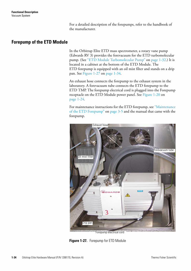
Functional DescriptionVacuum System
1-34 Orbitrap Elite Hardware Manual (P/N 1288170, Revision A) Thermo Fisher Scientific
For a detailed description of the forepumps, refer to the handbook of the manufacturer.
Forepump of the ETD Module
In the Orbitrap Elite ETD mass spectrometer, a rotary vane pump (Edwards RV 3) provides the forevacuum for the ETD turbomolecular pump. (See “ETD Module Turbomolecular Pump” on page 1-32.) It is located in a cabinet at the bottom of the ETD Module. The ETD forepump is equipped with an oil mist filter and stands on a drip pan. See Figure 1-27 on page 1-34.
An exhaust hose connects the forepump to the exhaust system in the laboratory. A forevacuum tube connects the ETD forepump to the ETD TMP. The forepump electrical cord is plugged into the Forepump receptacle on the ETD Module power panel. See Figure 1-20 on page 1-24.
For maintenance instructions for the ETD forepump, see “Maintenance of the ETD Forepump” on page 3-5 and the manual that came with the forepump.
Figure 1-27. Forepump for ETD Module
Forevacuum tube
Exhaust hose
Forepump electrical cord
Oil mist filter
Drip pan
Functional DescriptionVacuum System
Thermo Fisher Scientific Orbitrap Elite Hardware Manual (P/N 1288170, Revision A) 1-35
Vacuum System Controls
The power distribution board controls all turbomolecular pumps via voltage levels. See “Power Distribution Board” on page 1-53. An interface for RS485 data via the instrument control board connects the turbomolecular pumps with the linear ion trap. (See “Instrument Control Board” on page 1-52.) The turbomolecular pump of the linear ion trap and the ETD turbomolecular pump have individual controllers.
Vacuum Gauges
Several vacuum gauges monitor the vacuum within the instrument:
• The forevacuum of the Orbitrap Elite mass spectrometer is monitored by an Active Pirani gauge (TPR 280, manufacturer: Pfeiffer) connected to the forevacuum line. See Figure 1-24 on page 1-31.
• The high vacuum of the Orbitrap Elite mass spectrometer is monitored by a Cold Ion Gauge (IKR 270, manufacturer: Pfeiffer) connected to the UHV chamber. See Figure 1-25 on page 1-32. Because the gauge would be contaminated at higher pressures, it is turned on only when the forevacuum has fallen below a safety threshold (<10-2 mbar).
• The linear ion trap vacuum is monitored by a Convectron™ gauge and an ion gauge. Refer to the LTQ Series Hardware Manual for more information.
• In the Orbitrap Elite ETD mass spectrometer, two dedicated vacuum gauges monitor the vacuum in the ETD Module. A Convectron gauge (see Figure 1-17 on page 1-22 and Figure 1-18 on page 1-23) monitors the pressure in the ETD forevacuum line and an ion gauge (see Figure 1-17) monitors the pressure in the reagent ion source. Table 1-3 shows typical pressure readings in the ETD Module.
The vacuum gauges of the Orbitrap Elite mass spectrometer are connected to the power distribution board that directly responds to the pressure values. (See “Power Distribution Board” on page 1-53.) The analog values are digitized by the instrument control board. (See “Instrument Control Board” on page 1-52.) They are then sent as readout values to the data system.
Table 1-3. Typical pressure readings in the ETD Module
Conditions Convection Gauge Reading Ion Gauge Reading
CI gas pressure set to 20 psi 0.1–0.01 Torr 20–35×10-5 Torr

Functional DescriptionVacuum System
1-36 Orbitrap Elite Hardware Manual (P/N 1288170, Revision A) Thermo Fisher Scientific
Switching on the Vacuum System
When the vacuum system is switched on, the following occurs:
1. After the Vacuum Pumps switch is switched On, the pumps of the linear ion trap and the Orbitrap Elite mass spectrometer are run up. The Pirani gauge (see above) controls the Orbitrap Elite MS low vacuum pressure as well as the pressure at the forevacuum pumps. Within a short time, a significant pressure decrease must be observed. The goodness of the vacuum can be estimated by means of the rotation speed of the turbomolecular pumps (for example, 80% after 15 minutes).
2. If the working pressure is not reached after the preset time, the complete system is switched off. At the status LED panel of the power distribution board, an error message (Vacuum Failure) is put out (see below).
3. The Cold Ion Gauge is only switched on after the low vacuum is reached. It is then used to monitor the vacuum in the Orbitrap analyzer region.
Vacuum Failure
In case the pressure in the Orbitrap Elite mass spectrometer or the linear ion trap exceeds a safety threshold, the complete system including linear ion trap, electronics, and pumps is switched off. However, the power distribution is kept under current and puts out an error message at the LED panel. (See “Power Distribution Board” on page 1-53.) It can be reset by switching the main power switch off and on. (See “Main Power Switch” on page 1-9.)
Upon venting, the vent valves of the turbomolecular pumps on the Orbitrap analyzer stay closed. Only the vent valve of the linear ion trap is used. (See “Vent Valve of the Linear Ion Trap” on page 1-39.)
Vacuum System Heating during a System Bakeout
After the system has been open to the atmosphere (for example, for maintenance work), the vacuum deteriorates due to contaminations of the inner parts of the vacuum system caused by moisture or a power outage. These contaminations must be removed by heating the vacuum system: a system bakeout. See “Baking Out the System” on page 3-4.

Functional DescriptionGas Supply
Thermo Fisher Scientific Orbitrap Elite Hardware Manual (P/N 1288170, Revision A) 1-37
Gas SupplyThis section describes the gas supplies for the mass analyzers of the Orbitrap Elite mass spectrometer and the reagent ion source of the Orbitrap Elite ETD mass spectrometer.
Gas Supply for the Mass Analyzers
Figure 1-28 shows a schematical view of the gas supply for the instrument. The gas supply of the ETD system is highlighted in gray.
1
Gas Inlet Ports of the Instrument
On its right side (See Figure 1-9 on page 1-10.), the instrument provides three gas inlet ports for the gas supply of the mass analyzers:
• Nitrogen: The linear trap requires high-purity (99%) nitrogen for the API sheath gas and auxiliary/sweep gas. The required gas pressure is 690 ± 140 kPa (6.9 ± 1.4 bar, 100 ± 20 psi).
1 The port named Collision Gas is not used in the Orbitrap Elite MS.
Figure 1-28. Schematic of gas supply for Orbitrap Elite ETD MSa
a For parts lists of the gas supply, see page 4-4 and page 4-5.
Nitrogen (N2)Collision gas1Helium (He)
Analyzer
N2 venting TMP 4
TMP 1
Vent valve
C-Trap
HCD Cell
TMP 3
Linear Trap
TMP 2
Cooling Gas
ETD reagent carrier gas
ETD Module
Regulator with manometer

Functional DescriptionGas Supply
1-38 Orbitrap Elite Hardware Manual (P/N 1288170, Revision A) Thermo Fisher Scientific
In the Orbitrap Elite ETD mass spectrometer, the ETD system uses the high-purity nitrogen for cooling the reagent vials when the reagent ion source is turned off.
• Helium: The linear trap requires ultra-high purity (99.999%) helium for the collision gas. The required gas pressure is 275 ± 70 kPa (2.75 ± 0.7 bar, 40 ±10 psi).
To connect the nitrogen source to the Orbitrap Elite mass spectrometer
1. Connect an appropriate length of Teflon™ tubing to the nitrogen source in the laboratory. The Installation Kit contains 6 m (20 ft) of suitable Teflon tubing (OD 6 mm, P/N 0690280). The connection for the Teflon hose to the nitrogen gas supply is not provided in the kit; you have to supply this part.
2. Connect the opposite end of the Teflon tubing to the press-in fitting labeled Nitrogen, which is located at the right side of the instrument. See Figure 1-9 on page 1-10. To connect the tubing, align the Teflon tubing with the opening in the fitting and firmly push the tubing into the fitting until the tubing is secure.
To connect the helium source to the Orbitrap Elite mass spectrometer
1. Connect an appropriate length of 1/8-in. ID copper or stainless steel tubing with a brass Swagelok-type 1/8-in. nut (P/N 00101-15500) and a 2-piece brass 1/8-in. ID ferrule [P/N 00101-08500 (front), P/N 00101-2500 (back)] to the Helium gas inlet. See Figure 1-29 for the proper orientation of the fitting and ferrule.
2. Connect the opposite end of the tubing to the helium gas source, using an appropriate fitting.
Warning Danger of Asphyxiation. Accumulation of nitrogen gas could displace sufficient oxygen to suffocate personnel in the laboratory. Ensure that the laboratory is well ventilated.
Figure 1-29. Proper orientation of the Swagelok-type nut and two-piece ferrule
Gas hose Front ferrule
Swagelok-type nut Back ferrule

Functional DescriptionGas Supply
Thermo Fisher Scientific Orbitrap Elite Hardware Manual (P/N 1288170, Revision A) 1-39
Gas Distribution Within the Instrument
Helium gas is led from the helium port through a stainless steel capillary to the right rear side of the linear trap. See Figure 1-28 on page 1-37. High purity nitrogen gas is led from the nitrogen port via Teflon tubing to the right side of the Orbitrap Elite mass spectrometer. Here, two T-pieces divide the nitrogen gas flow into three parts.
The first part of the high purity nitrogen gas flow is directed through Teflon tubing via a pressure regulator to the vent valve of the linear trap. (See Figure 1-30 on page 1-39.) The second part of the nitrogen flow is directed through Teflon tubing to the API source. The third part of the nitrogen flow enters a gas regulator with manometer, which keeps the gas pressure to the C-Trap and HCD cell constant. (See Figure 1-30, background.) From the regulator, the collision gas is led through red PEEKSil™ tubing (100 mm ID silica capillary in 1/16 inch PEEK tubing) to the collision octapole next to the curved linear trap (flow rate: ~0.5 mL/min). The nitrogen gas leaking from the HCD collision cell (3–5 mbar) is used for ion trapping and cooling in the C-Trap.
In the Orbitrap Elite ETD mass spectrometer, nitrogen is also directed through Teflon tubing to the ETD Module to be used for cooling the reagent vials when the reagent ion source is turned off.
Vent Valve of the Linear Ion Trap
If the system and pumps are switched off, the system is vented. The vent valve is controlled by the linear ion trap. The LTQ Series Hardware Manual contains further information about the vent valve.
Figure 1-30. Gas regulators
Gas for HCD and C-Trap
Gas for Vent Valve
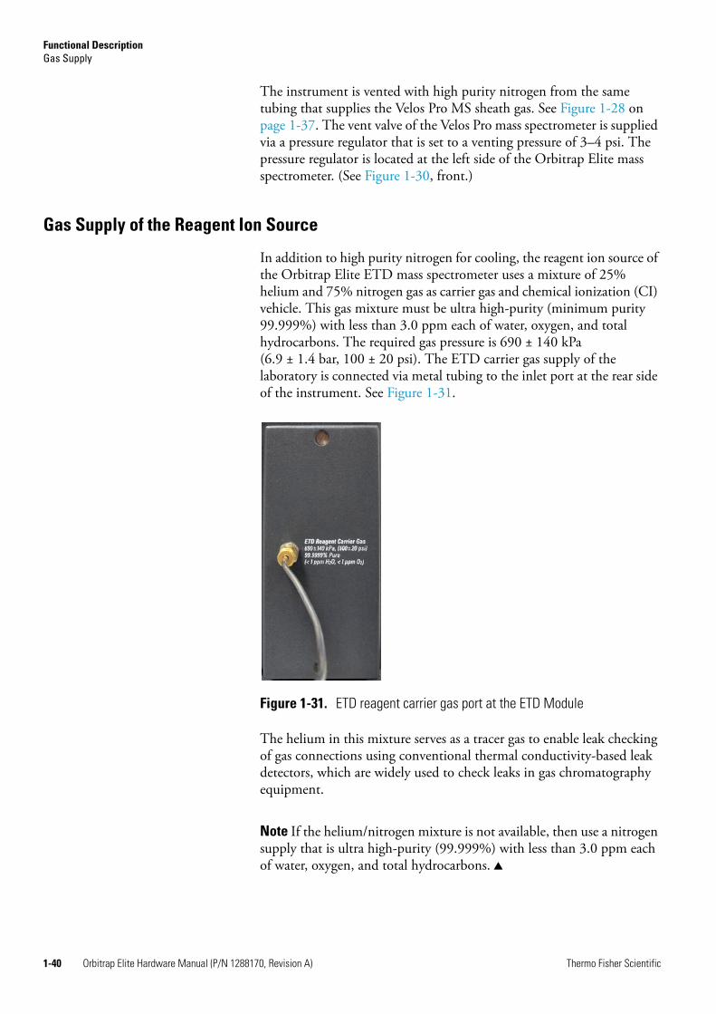
Functional DescriptionGas Supply
1-40 Orbitrap Elite Hardware Manual (P/N 1288170, Revision A) Thermo Fisher Scientific
The instrument is vented with high purity nitrogen from the same tubing that supplies the Velos Pro MS sheath gas. See Figure 1-28 on page 1-37. The vent valve of the Velos Pro mass spectrometer is supplied via a pressure regulator that is set to a venting pressure of 3–4 psi. The pressure regulator is located at the left side of the Orbitrap Elite mass spectrometer. (See Figure 1-30, front.)
Gas Supply of the Reagent Ion Source
In addition to high purity nitrogen for cooling, the reagent ion source of the Orbitrap Elite ETD mass spectrometer uses a mixture of 25% helium and 75% nitrogen gas as carrier gas and chemical ionization (CI) vehicle. This gas mixture must be ultra high-purity (minimum purity 99.999%) with less than 3.0 ppm each of water, oxygen, and total hydrocarbons. The required gas pressure is 690 ± 140 kPa (6.9 ± 1.4 bar, 100 ± 20 psi). The ETD carrier gas supply of the laboratory is connected via metal tubing to the inlet port at the rear side of the instrument. See Figure 1-31.
The helium in this mixture serves as a tracer gas to enable leak checking of gas connections using conventional thermal conductivity-based leak detectors, which are widely used to check leaks in gas chromatography equipment.
Note If the helium/nitrogen mixture is not available, then use a nitrogen supply that is ultra high-purity (99.999%) with less than 3.0 ppm each of water, oxygen, and total hydrocarbons.
Figure 1-31. ETD reagent carrier gas port at the ETD Module
Functional DescriptionGas Supply
Thermo Fisher Scientific Orbitrap Elite Hardware Manual (P/N 1288170, Revision A) 1-41
Triple Gas Filter
A triple (oxygen/water/hydrogen) gas filter is installed between the regulator on the reagent carrier gas source and the ETD module to ensure that the reagent carrier gas (either nitrogen or helium/nitrogen) is better than 99.999% pure with much less than 1 ppm of oxygen, water, and hydrocarbons.
Refer to the filter manufacturer’s instructions for information about how to monitor the color changes in the filters that indicated when the filters need to be replaced, as well as information about where to order new filters. If there are no leaks in the reagent carrier gas plumbing, you can expect the filters to last a year or more. Thermo Fisher Scientific strongly recommends that a Thermo Fisher Scientific field service engineer replace the gas filters.

Functional DescriptionCooling Water Circuit
1-42 Orbitrap Elite Hardware Manual (P/N 1288170, Revision A) Thermo Fisher Scientific
Cooling Water CircuitFigure 1-32 on page 1-42 shows a schematical view of the cooling water circuit in the Orbitrap Elite mass spectrometer. For a parts list of the cooling water circuit, see page 4-4. Cooling water at a temperature of 20 °C enters and leaves the instrument at the bottom of the right side. See Figure 1-9 on page 1-10. First, the fresh water passes through the turbomolecular pumps in the order TMP 3 → TMP 1 → TMP 4 → TMP 2. Then it passes through the heating element (Peltier element) that maintains (±0.5 °C) the preset temperature of the analyzer. After that, the cooling water passes through the preamplifier cooling unit. Before it leaves the instrument, the water passes through the other Peltier element at the back of the central electrode power supply board.
A flow control sensor is connected to the power distribution board and allows displaying the current flow rate of the cooling water in the software. An inline filter, which is installed upstream, protects the sensor. It must be replaced annually, see page 3-58 for instructions.
Figure 1-32. Schematic of cooling water circuit
Recirculating chiller
Flow control sensor
TMP 4 Water cooler for TMPCentral Electrode Power Supply Box
Peltier element
TMP 3
Power Distribution Board
Linear Trap
Heating element (Peltier element)
Analyzer
Inpu
t
Outp
ut
TMP 1
Preamplifier cooling
Water filter
TMP 2
Functional DescriptionCooling Water Circuit
Thermo Fisher Scientific Orbitrap Elite Hardware Manual (P/N 1288170, Revision A) 1-43
Recirculating Chiller
A recirculating chiller (Thermo Scientific NESLAB ThermoFlex™ 900) is shipped with the instrument, making the mass spectrometer independent from any cooling water supply. A wall receptacle provides the electric power for the chiller. Two water hoses (black), internal diameter 9 mm, wall thickness 3 mm, length approx. 3 m (~10 ft) are shipped with the instrument.
For instruction about performing maintenance for the chiller, see “Maintenance of the Cooling Circuit” on page 3-58. See also the manufacturer’s manual for the chiller.
Properties of Cooling Water
The water temperature is not critical, but should be in the range of 20 to 25 °C (68 to 77 °F). Lower temperatures could lead to a condensation of atmospheric water vapor. It is recommended to use distilled water rather than de-ionized water due to lower concentration of bacteria and residual organic matter.
The water should be free of suspended matter to avoid clogging of the cooling circuit. In special cases, an in-line filter is recommended to guarantee consistent water quality.
The cooling water should meet the following requirements:
Hardness: <0.05 ppmResistivity: 1–3 MΩ/cmTotal dissolved solids: <10 ppmpH: 7–8
Warning Burn Hazard. If the water circuit fails, all parts of the water distribution unit may be considerably heated up. Do not touch the parts! Before disconnecting the cooling water hoses, make sure the cooling water has cooled down!
Functional DescriptionPrinted Circuit Boards
1-44 Orbitrap Elite Hardware Manual (P/N 1288170, Revision A) Thermo Fisher Scientific
Printed Circuit BoardsThe Orbitrap Elite mass spectrometer is controlled by a PC running the Xcalibur™ software suite. The software controls all aspects of the instrument. The main software elements are the communication with the linear ion trap, the control of ion detection, and the control of the Orbitrap analyzer.
The following pages contain a short overview of the electronic boards in the MS portion of the Orbitrap Elite mass spectrometer. For each board, its respective location and function are given. If applicable, the diagnostic LEDs on the board are described. For a description of the printed circuit boards in the ETD Module, see “ETD Module” on page 1-21.
The electronics of the Orbitrap Elite mass spectrometer contains complicated and numerous circuits. Therefore, only qualified and skilled electronics engineers should perform servicing.
A Thermo Fisher Scientific field service engineer should be called if servicing is required. It is further recommended to use Thermo Fisher Scientific spare parts only. When replacing fuses, only use the correct type. Before calling a service engineer, please try to localize the defect via errors indicated in the software or diagnostics. A precise description of the defect will ease the repair and reduce the costs.
Note Many of the electronic components can be tested by the Orbitrap Elite MS diagnostics, which is accessible from the Tune Plus window.
Warning Electrical Shock Hazard. Parts of the printed circuit boards are at high voltage. Shut down the instrument and disconnect it from line power before performing service. Opening the electronics cabinet is only allowed for maintenance purposes by qualified personnel.
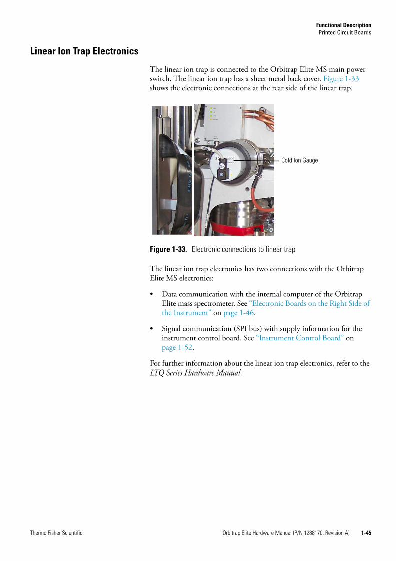
Functional DescriptionPrinted Circuit Boards
Thermo Fisher Scientific Orbitrap Elite Hardware Manual (P/N 1288170, Revision A) 1-45
Linear Ion Trap Electronics
The linear ion trap is connected to the Orbitrap Elite MS main power switch. The linear ion trap has a sheet metal back cover. Figure 1-33 shows the electronic connections at the rear side of the linear trap.
The linear ion trap electronics has two connections with the Orbitrap Elite MS electronics:
• Data communication with the internal computer of the Orbitrap Elite mass spectrometer. See “Electronic Boards on the Right Side of the Instrument” on page 1-46.
• Signal communication (SPI bus) with supply information for the instrument control board. See “Instrument Control Board” on page 1-52.
For further information about the linear ion trap electronics, refer to the LTQ Series Hardware Manual.
Figure 1-33. Electronic connections to linear trap
Cold Ion Gauge
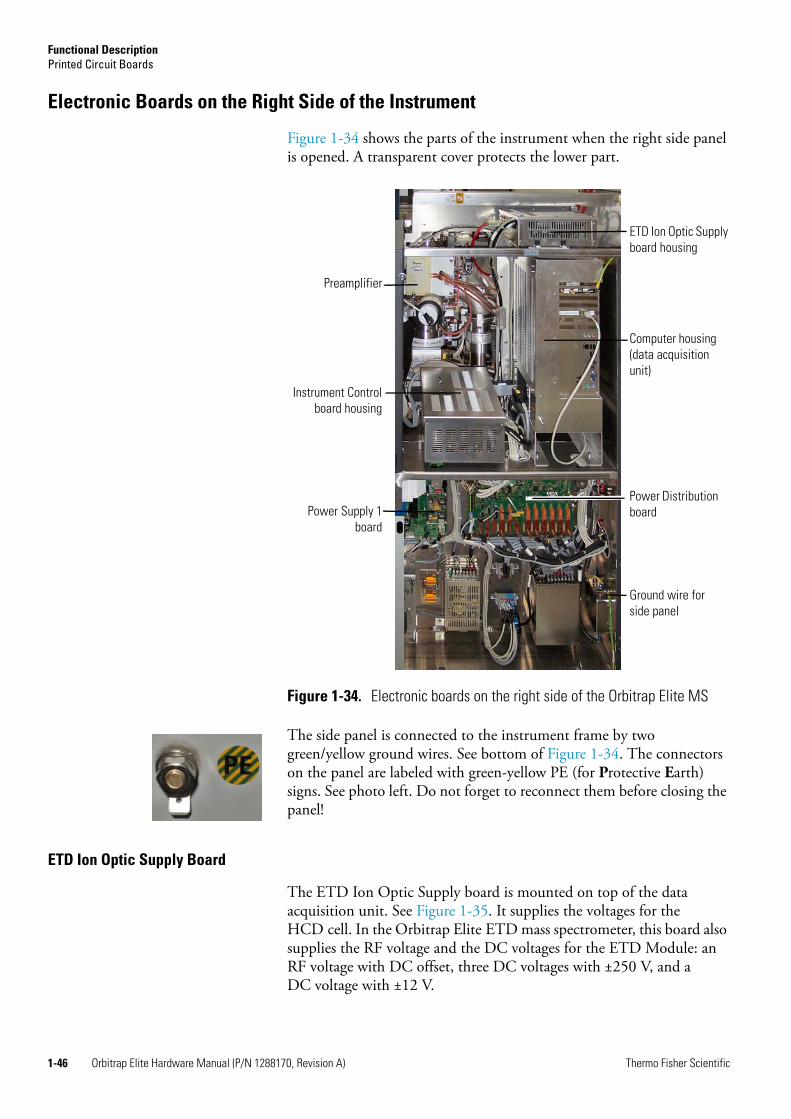
Functional DescriptionPrinted Circuit Boards
1-46 Orbitrap Elite Hardware Manual (P/N 1288170, Revision A) Thermo Fisher Scientific
Electronic Boards on the Right Side of the Instrument
Figure 1-34 shows the parts of the instrument when the right side panel is opened. A transparent cover protects the lower part.
The side panel is connected to the instrument frame by two green/yellow ground wires. See bottom of Figure 1-34. The connectors on the panel are labeled with green-yellow PE (for Protective Earth) signs. See photo left. Do not forget to reconnect them before closing the panel!
ETD Ion Optic Supply Board
The ETD Ion Optic Supply board is mounted on top of the data acquisition unit. See Figure 1-35. It supplies the voltages for the HCD cell. In the Orbitrap Elite ETD mass spectrometer, this board also supplies the RF voltage and the DC voltages for the ETD Module: an RF voltage with DC offset, three DC voltages with ±250 V, and a DC voltage with ±12 V.
Figure 1-34. Electronic boards on the right side of the Orbitrap Elite MS
Computer housing (data acquisition unit)
Instrument Controlboard housing
Power Distribution boardPower Supply 1
board
Preamplifier
Ground wire for side panel
ETD Ion Optic Supply board housing

Functional DescriptionPrinted Circuit Boards
Thermo Fisher Scientific Orbitrap Elite Hardware Manual (P/N 1288170, Revision A) 1-47
The diagnostic LEDs on the ETD ion optic supply board are listed in Table 1-4 on page 1-47. The positions of the diagnostic LEDs on the board are indicated by white rectangles in Figure 1-36.
Figure 1-35. ETD Ion Optic Supply board
Table 1-4. Diagnostic LEDs on the ETD Ion Optic Supply board
No. Name Color Description Normal Operating Condition
LD1 +275 V Green +275 V input voltage present On
LD2 -275 V Green -275 V input voltage present On
LD3 RF Supply Green RF input voltage (22 V) present On
LD4 +24 V Green +24 V input voltage present On
LD5 +15 V Green +15 V input voltage present On
LD6 -15 V Green -15 V input voltage present On
LD7 RF1_ON Blue RF-generator switched on On/Off, depending on active application

Functional DescriptionPrinted Circuit Boards
1-48 Orbitrap Elite Hardware Manual (P/N 1288170, Revision A) Thermo Fisher Scientific
Preamplifier
The preamplifier is located in a housing next to the Cold Ion Gauge. See Figure 1-36. It is water cooled to protect it during a system bakeout.
This board is a broadband preamplifier with differential high-impedance inputs. It serves as a detection amplifier and impedance converter for the image current created by the oscillating ions. The output current is transferred to the data acquisition board. It has an amplification factor of about 60 dB and covers the frequency range from 15 kHz to 10 MHz.
The diagnostic LEDs on the preamplifier are listed in Table 1-5 on page 1-49. The positions of the diagnostic LEDs on the board are indicated by white rectangles in Figure 1-36.
Figure 1-36. Preamplifier
Cold Ion Gauge
Cooling water supply for Peltier element
Cooling water supply for Preamplifier

Functional DescriptionPrinted Circuit Boards
Thermo Fisher Scientific Orbitrap Elite Hardware Manual (P/N 1288170, Revision A) 1-49
Internal Computer
Figure 1-37 shows the components of the data acquisition unit. The unit is mounted in a housing located at the right side of the instrument.
The internal computer contains a computer mainboard with an ATX power supply. The data acquisition digital PCI board is directly plugged into the mainboard. The data acquisition analog board is mounted on top of the computer mainboard.
Table 1-5. Diagnostic LEDs on the Preamplifier board
No. Name Color Description Normal Operating Condition
LD1 Overload Yellow RF output is overloaded Off
LD2 +5 V Green +5 V input voltage present On
LD3 +15 V Green +15 V input voltage present On
LD4 -5 V Green -5 V input voltage present On
LD5 Input off Yellow RF inputs are shortened (protection)
On, off during Detect
Figure 1-37. Data Acquisition unit
Instrument Control board housing
Computer housing with Data Acquisition Analog board, Data Acquisition Digital PCI board, and Power Supply 2 board
ETD Ion Optic Supply board housing

Functional DescriptionPrinted Circuit Boards
1-50 Orbitrap Elite Hardware Manual (P/N 1288170, Revision A) Thermo Fisher Scientific
Data Acquisition Digital PCI Board
Figure 1-38 shows the data acquisition digital PCI board. It is an add-on board to the internal computer. (See Figure 1-37 on page 1-49.)
This board is used to convert detected ion signals to digital form and to interface to the computer mainboard. The board has two 16 bit parallel connections to the DAC and the ADC on the data acquisition analog board, which are used for controlling and reading-back signals. A high-speed link port channel is also on the board that is used to communicate with the electronics in the linear ion trap.
Precision timing is derived from the data acquisition analog board and events with lower requirements use the timer in the internal computer. This timer is used to check at regular intervals whether the foreground process works as expected.
Communication takes place not only between the linear ion trap and the internal computer of the Orbitrap Elite system, but also between the linear ion trap and the data system computer. For further information about the data system, refer to the LTQ Series Hardware Manual.
The diagnostic LEDs listed in Table 1-6 show the status of the board. The position of the LEDs on the board is indicated by a red rectangle in Figure 1-38.
Figure 1-38. Data Acquisition Digital PCI board
Table 1-6. Diagnostic LEDs of the Data Acquisition Digital PCI board
Name Color Description Normal Operating Condition
+5 V Green +5 V voltage present On
+3.3 V Green +3.3 V voltage present On
+2.5 V Green +2.5 V voltage present On

Functional DescriptionPrinted Circuit Boards
Thermo Fisher Scientific Orbitrap Elite Hardware Manual (P/N 1288170, Revision A) 1-51
Data Acquisition Analog Board
Figure 1-39 shows the data acquisition analog board. This board is an add-on board to the mainboard of the internal computer. See Figure 1-37 on page 1-49. It is used to convert analog to digital signals for Orbitrap analyzer experiments, especially for detecting the ions. The board contains an ADC for the detection of the transient signal, with a frequency range from 10 kHz to 10 MHz. Three anti-aliasing filters for the low, middle and high mass range are automatically selected by the software.The data acquisition board provides precision timing to control the acquisition. Events with lower timing requirements on accuracy are controlled by the linear ion trap.
The diagnostic LEDs listed in Table 1-7 on page 1-51 show the status of the voltages applied to the board. The position of the LEDs on the board is indicated by a white rectangle in Figure 1-39.
Power Supply 2 Board
The power supply 2 board provides the supply voltages for the data acquisition analog board. It is mounted to the back inside the housing of the internal computer. See Figure 1-37 on page 1-49.
Figure 1-39. Data Acquisition Analog board
Table 1-7. Diagnostic LEDs of the Data Acquisition Analog board
Name Color Description Normal Operating Condition
+5 V Green +5 V voltage present On
-5 V Green -5 V voltage present On
+3.3 V Green +3.3 V voltage present On

Functional DescriptionPrinted Circuit Boards
1-52 Orbitrap Elite Hardware Manual (P/N 1288170, Revision A) Thermo Fisher Scientific
The diagnostic LEDs listed in Table 1-8 show the status of the voltages applied to the board.
Instrument Control Board
Figure 1-40 shows the instrument control board. The instrument control board is located in a housing next to the internal computer. It is connected to the Orbitrap Elite MS main power.
The instrument control board is used to interface the Velos Pro MS control electronics to the Orbitrap analyzer control electronics. Three signal lines are passed from the Velos Pro MS: a digital, parallel (DAC) bus, a serial SPI bus, and a Link Port Signal line. The instrument control board contains a micro controller, digital and analog converters, and serial port connectors.
Table 1-8. Diagnostic LEDs of the Power Supply 2 board
Name Color Description Normal Operating Condition
+5.1 V Green +5.1 V voltage present On
-5.1 V Green -5.1 V voltage present On
+3.3 V Green +3.3 V voltage present On
Figure 1-40. Instrument Control board
Status LEDsDiagnostic LEDs
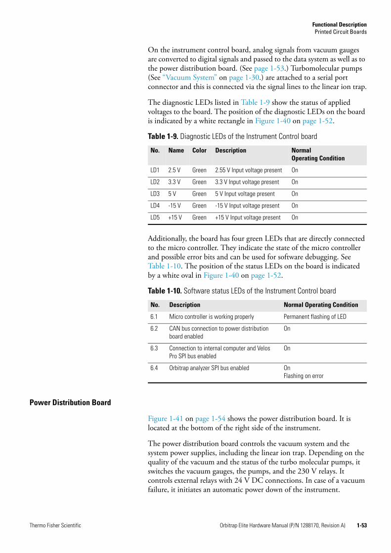
Functional DescriptionPrinted Circuit Boards
Thermo Fisher Scientific Orbitrap Elite Hardware Manual (P/N 1288170, Revision A) 1-53
On the instrument control board, analog signals from vacuum gauges are converted to digital signals and passed to the data system as well as to the power distribution board. (See page 1-53.) Turbomolecular pumps (See “Vacuum System” on page 1-30.) are attached to a serial port connector and this is connected via the signal lines to the linear ion trap.
The diagnostic LEDs listed in Table 1-9 show the status of applied voltages to the board. The position of the diagnostic LEDs on the board is indicated by a white rectangle in Figure 1-40 on page 1-52.
Additionally, the board has four green LEDs that are directly connected to the micro controller. They indicate the state of the micro controller and possible error bits and can be used for software debugging. See Table 1-10. The position of the status LEDs on the board is indicated by a white oval in Figure 1-40 on page 1-52.
Power Distribution Board
Figure 1-41 on page 1-54 shows the power distribution board. It is located at the bottom of the right side of the instrument.
The power distribution board controls the vacuum system and the system power supplies, including the linear ion trap. Depending on the quality of the vacuum and the status of the turbo molecular pumps, it switches the vacuum gauges, the pumps, and the 230 V relays. It controls external relays with 24 V DC connections. In case of a vacuum failure, it initiates an automatic power down of the instrument.
Table 1-9. Diagnostic LEDs of the Instrument Control board
No. Name Color Description Normal Operating Condition
LD1 2.5 V Green 2.55 V Input voltage present On
LD2 3.3 V Green 3.3 V Input voltage present On
LD3 5 V Green 5 V Input voltage present On
LD4 -15 V Green -15 V Input voltage present On
LD5 +15 V Green +15 V Input voltage present On
Table 1-10. Software status LEDs of the Instrument Control board
No. Description Normal Operating Condition
6.1 Micro controller is working properly Permanent flashing of LED
6.2 CAN bus connection to power distribution board enabled
On
6.3 Connection to internal computer and Velos Pro SPI bus enabled
On
6.4 Orbitrap analyzer SPI bus enabled OnFlashing on error
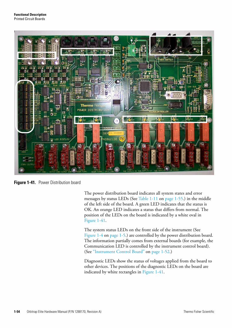
Functional DescriptionPrinted Circuit Boards
1-54 Orbitrap Elite Hardware Manual (P/N 1288170, Revision A) Thermo Fisher Scientific
The power distribution board indicates all system states and error messages by status LEDs (See Table 1-11 on page 1-55.) in the middle of the left side of the board. A green LED indicates that the status is OK. An orange LED indicates a status that differs from normal. The position of the LEDs on the board is indicated by a white oval in Figure 1-41.
The system status LEDs on the front side of the instrument (See Figure 1-4 on page 1-5.) are controlled by the power distribution board. The information partially comes from external boards (for example, the Communication LED is controlled by the instrument control board). (See “Instrument Control Board” on page 1-52.)
Diagnostic LEDs show the status of voltages applied from the board to other devices. The positions of the diagnostic LEDs on the board are indicated by white rectangles in Figure 1-41.
Figure 1-41. Power Distribution board
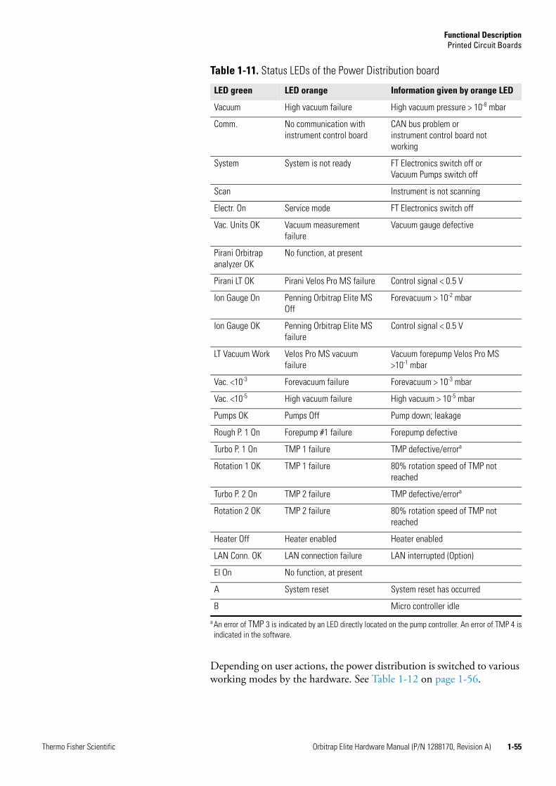
Functional DescriptionPrinted Circuit Boards
Thermo Fisher Scientific Orbitrap Elite Hardware Manual (P/N 1288170, Revision A) 1-55
Depending on user actions, the power distribution is switched to various working modes by the hardware. See Table 1-12 on page 1-56.
Table 1-11. Status LEDs of the Power Distribution board
LED green LED orange Information given by orange LED
Vacuum High vacuum failure High vacuum pressure > 10-8 mbar
Comm. No communication with instrument control board
CAN bus problem orinstrument control board not working
System System is not ready FT Electronics switch off orVacuum Pumps switch off
Scan Instrument is not scanning
Electr. On Service mode FT Electronics switch off
Vac. Units OK Vacuum measurement failure
Vacuum gauge defective
Pirani Orbitrap analyzer OK
No function, at present
Pirani LT OK Pirani Velos Pro MS failure Control signal < 0.5 V
Ion Gauge On Penning Orbitrap Elite MS Off
Forevacuum > 10-2 mbar
Ion Gauge OK Penning Orbitrap Elite MS failure
Control signal < 0.5 V
LT Vacuum Work Velos Pro MS vacuum failure
Vacuum forepump Velos Pro MS >10-1 mbar
Vac. <10-3 Forevacuum failure Forevacuum > 10-3 mbar
Vac. <10-5 High vacuum failure High vacuum > 10-5 mbar
Pumps OK Pumps Off Pump down; leakage
Rough P. 1 On Forepump #1 failure Forepump defective
Turbo P. 1 On TMP 1 failure TMP defective/errora
a An error of TMP 3 is indicated by an LED directly located on the pump controller. An error of TMP 4 isindicated in the software.
Rotation 1 OK TMP 1 failure 80% rotation speed of TMP not reached
Turbo P. 2 On TMP 2 failure TMP defective/errora
Rotation 2 OK TMP 2 failure 80% rotation speed of TMP not reached
Heater Off Heater enabled Heater enabled
LAN Conn. OK LAN connection failure LAN interrupted (Option)
EI On No function, at present
A System reset System reset has occurred
B Micro controller idle

Functional DescriptionPrinted Circuit Boards
1-56 Orbitrap Elite Hardware Manual (P/N 1288170, Revision A) Thermo Fisher Scientific
Table 1-13 shows the possible operating states of the power distribution.
Table 1-12. Working modes of the Power Distribution board
Action Consequences
a. Main switch off Complete system including linear ion trap and multiple socket outlets (ETD Module, for example) are without power
b. Vacuum Pumps switch off
Everything is switched off
c. FT Electronics switch off
All components are switched off with exception of the following ones:
• Heater control
• Multiple socket outlets
• Power distribution board
• Pumps
• Vacuum control
• Velos Pro MS (has a separate Service switch)
Table 1-13. Operating states of the Power Distribution board
Action Consequences
1. Main switch on, Vacuum Pumps switch off
Everything is switched off
2. Vacuum Pumps switch on and FT Electronics switch on
System starts up: pumps and electronics switched on
3. Check linear ion trap and Orbitrap Elite MS forevacuum pumps:
10-0 mbar after 30 s.
If not ok: switch off system and light error LEDa; power distribution remains switched on
4. After the system has started, the Pirani gauge returns a vacuum < 10-2 mbar and both TMPs reach 80% rotation speed
Switch on Penning gauge
5. Vacuum and 80% rotation speed of TMPs not reached after preset time (< 8 min, otherwise the pumps automatically switch off).
Switch off system (including linear ion trap) and light error LED*; power distribution remains switched on
6. One or more vacuum gauges defective (control signal < 0.5 V).
Light error LED only, otherwise ignore
7. After the operating status is reached, the pressure at one gauge exceeds the security threshold for more than the preset time period:
• Pirani gauge Orbitrap Elite MS >10-1 mbar
• Penning gauge Orbitrap Elite MS >10-3 mbar
• Pirani gauge Velos Pro MS forepump >10-1 mbar
System is shut down with exception of power distribution (light error LED).
Rebooting of the system by switching off/on of the main switch.

Functional DescriptionPrinted Circuit Boards
Thermo Fisher Scientific Orbitrap Elite Hardware Manual (P/N 1288170, Revision A) 1-57
Power Supply 1 Board
Figure 1-42 shows the power supply 1 board. This board is located next to the power distribution board. It provides the power for the ion optic supply board (See “Ion Optic Supply Board” on page 1-59.) and the instrument control board. (See “Instrument Control Board” on page 1-52.)
8. Rotation speed of a TMP falls below 80%
Shut down system (see 7.);
light LED* of corresponding pump.
9. Service switch linear ion trap off Linear ion trap electronics switched off, pumps keep on running;
Orbitrap Elite MS without data link, keeps on running
10. FT Electronics switch Orbitrap Elite MS off
Orbitrap Elite MS electronics switched off, pumps keep on running;
Orbitrap Elite MS without data link, keeps on running
11. Failure of linear ion trap or Orbitrap Elite MS (for example, fuse is opened).
If the vacuum in one part deteriorates, the complete system is shut down.
12. Mains failure System powers up after the electricity is available again. All devices reach the defined state. Linear ion trap and internal computer must reboot.
a After the shutdown, the LED flashes that represents the reason for the shutdown.
Table 1-13. Operating states of the Power Distribution board, continued
Action Consequences
Figure 1-42. Power Supply 1 board
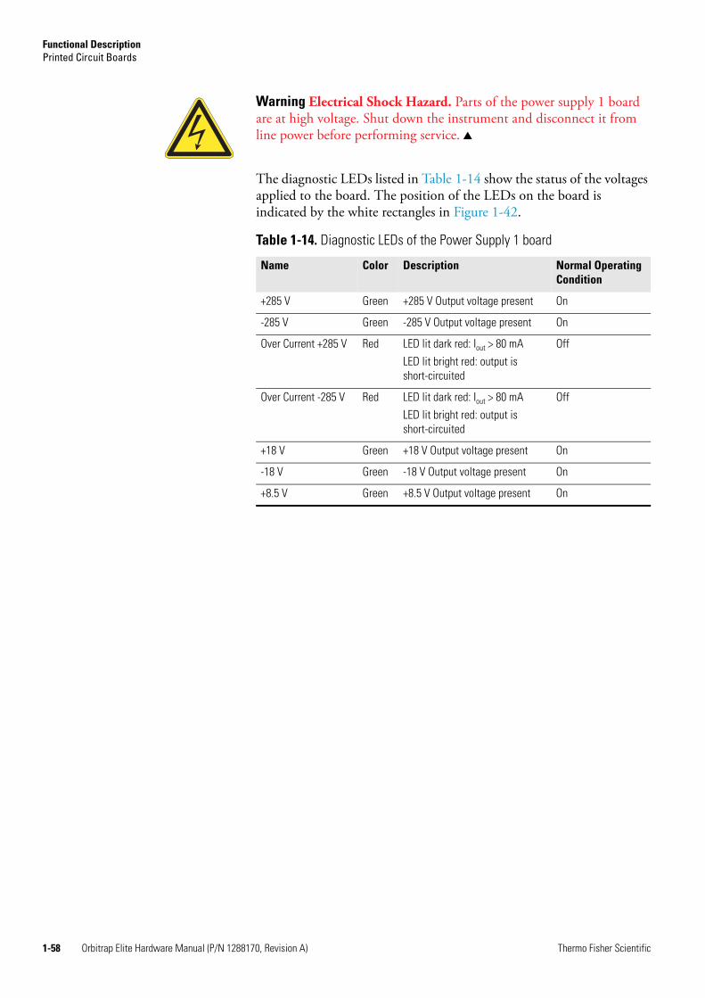
Functional DescriptionPrinted Circuit Boards
1-58 Orbitrap Elite Hardware Manual (P/N 1288170, Revision A) Thermo Fisher Scientific
The diagnostic LEDs listed in Table 1-14 show the status of the voltages applied to the board. The position of the LEDs on the board is indicated by the white rectangles in Figure 1-42.
Warning Electrical Shock Hazard. Parts of the power supply 1 board are at high voltage. Shut down the instrument and disconnect it from line power before performing service.
Table 1-14. Diagnostic LEDs of the Power Supply 1 board
Name Color Description Normal OperatingCondition
+285 V Green +285 V Output voltage present On
-285 V Green -285 V Output voltage present On
Over Current +285 V Red LED lit dark red: Iout > 80 mA
LED lit bright red: output is short-circuited
Off
Over Current -285 V Red LED lit dark red: Iout > 80 mA
LED lit bright red: output is short-circuited
Off
+18 V Green +18 V Output voltage present On
-18 V Green -18 V Output voltage present On
+8.5 V Green +8.5 V Output voltage present On

Functional DescriptionPrinted Circuit Boards
Thermo Fisher Scientific Orbitrap Elite Hardware Manual (P/N 1288170, Revision A) 1-59
Electronic Boards on the Left Side of the Instrument
Figure 1-43 shows the left side of the instrument with the panel opened. This side of the instrument contains mostly boards that are part of the Orbitrap analyzer control.
The main components on this side are described starting from the top.
Ion Optic Supply Board
Figure 1-44 on page 1-60 shows the ion optic supply board. The board is located in a housing on top of the left instrument side of the instrument. This board supplies the voltages and the radio frequency for the ion guides and interoctapole lenses of the Orbitrap Elite mass spectrometer. It has an RF detector for the RF output control. The
Figure 1-43. Electronic boards on the left side of the instrument
Ion Optic Supply board housing
Central ElectrodePower Supply board
housing
Central Electrode Pulser board housing
TemperatureController board
High Voltage Power Supply board housing
CLT RF Main board housing with RF Off & Feedback board and CLT Offset Connector

Functional DescriptionPrinted Circuit Boards
1-60 Orbitrap Elite Hardware Manual (P/N 1288170, Revision A) Thermo Fisher Scientific
board also provides the trap voltage, the gate voltage, and the reflector DC voltages as well as the RF voltages to the octapole of the Orbitrap analyzer. See “Orbitrap Analyzer” on page 1-14 for further information.
The diagnostic LEDs listed in Table 1-15 show the status of applied voltages to the board. The position of the LEDs on the board is indicated by white rectangles in Figure 1-44.
Figure 1-44. Ion Optic Supply board
Warning Electrical Shock Hazard. Parts of the board are at high voltage. Shut down the instrument and disconnect it from line power before performing service.
Table 1-15. Diagnostic LEDs of the Ion Optic Supply board
No. Name Color Description Normal Operating Condition
LD1 +275 V Green +275 V Input voltage present On
LD2 -275 V Green -275 V Input voltage present On
LD3 +29 V Green +29 V Input voltage present On
LD5 +15 V Green +15 V Input voltage present On
LD6 -15 V Green -15 V Input voltage present On
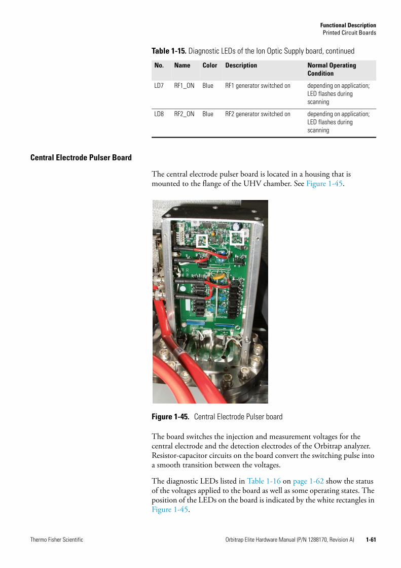
Functional DescriptionPrinted Circuit Boards
Thermo Fisher Scientific Orbitrap Elite Hardware Manual (P/N 1288170, Revision A) 1-61
Central Electrode Pulser Board
The central electrode pulser board is located in a housing that is mounted to the flange of the UHV chamber. See Figure 1-45.
The board switches the injection and measurement voltages for the central electrode and the detection electrodes of the Orbitrap analyzer. Resistor-capacitor circuits on the board convert the switching pulse into a smooth transition between the voltages.
The diagnostic LEDs listed in Table 1-16 on page 1-62 show the status of the voltages applied to the board as well as some operating states. The position of the LEDs on the board is indicated by the white rectangles in Figure 1-45.
LD7 RF1_ON Blue RF1 generator switched on depending on application; LED flashes during scanning
LD8 RF2_ON Blue RF2 generator switched on depending on application; LED flashes during scanning
Table 1-15. Diagnostic LEDs of the Ion Optic Supply board, continued
No. Name Color Description Normal Operating Condition
Figure 1-45. Central Electrode Pulser board
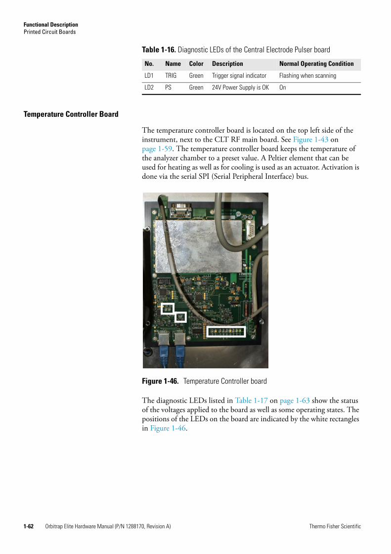
Functional DescriptionPrinted Circuit Boards
1-62 Orbitrap Elite Hardware Manual (P/N 1288170, Revision A) Thermo Fisher Scientific
Temperature Controller Board
The temperature controller board is located on the top left side of the instrument, next to the CLT RF main board. See Figure 1-43 on page 1-59. The temperature controller board keeps the temperature of the analyzer chamber to a preset value. A Peltier element that can be used for heating as well as for cooling is used as an actuator. Activation is done via the serial SPI (Serial Peripheral Interface) bus.
The diagnostic LEDs listed in Table 1-17 on page 1-63 show the status of the voltages applied to the board as well as some operating states. The positions of the LEDs on the board are indicated by the white rectangles in Figure 1-46.
Table 1-16. Diagnostic LEDs of the Central Electrode Pulser board
No. Name Color Description Normal Operating Condition
LD1 TRIG Green Trigger signal indicator Flashing when scanning
LD2 PS Green 24V Power Supply is OK On
Figure 1-46. Temperature Controller board

Functional DescriptionPrinted Circuit Boards
Thermo Fisher Scientific Orbitrap Elite Hardware Manual (P/N 1288170, Revision A) 1-63
CLT RF Unit
The CLT RF unit comprises the CLT RF main board and the RF off & feedback board. The unit operates the curved linear trap (CLT) with four phases RF voltage and three pulsed DC voltages (PUSH, PULL, and OFFSET).
The CLT RF main board is located in a housing in the center of the left side of the instrument. See Figure 1-43 on page 1-59. This board provides an RF voltage (“Main RF”) for the curved linear trap. It allows switching off the RF and simultaneous pulsing of each CLT electrode. See “Orbitrap Analyzer” on page 1-14 for further information. The board communicates with the instrument control board via an SPI bus.
Table 1-17. Diagnostic LEDs of the Temperature Controller board
No. Name Color Description Normal OperatingCondition
LD1 +15 V Green +15 V Input voltage present On
LD2 -15 V Green -15 V Input voltage present On
LD3 TEC >60C Yellow Temperature of cold side Peltier element above 60 ºC
Off
LD4 Unit >60C Yellow Temperature of UNIT heat sink above 60 ºC
Off
LD5 Reg Off Yellow Control switched off Off
LD6 No Term Yellow SPI bus termination board missing
Off
LD7 SDT enable Green Interface has been addressed and sends/receives data
Flashing on SPI bus data transfer
LD8 SEL Green Board has been addressed Flashing on SPI bus data transfer
LD9 Heating Yellow Peltier element is heating Depending on system state
LD10 Cooling Yellow Peltier element is cooling Depending on system state
LD11 UR>0 Yellow Summation voltage controller >0 V
Off when adjusted
LD12 UR<0 Yellow Summation voltage controller <0 V
Off when adjusted

Functional DescriptionPrinted Circuit Boards
1-64 Orbitrap Elite Hardware Manual (P/N 1288170, Revision A) Thermo Fisher Scientific
The diagnostic LEDs listed in Table 1-18 show the status of the voltages applied to the board as well as some operating states. The position of the LEDs on the board is indicated by the white rectangles in Figure 1-47.
The RF off & feedback board is an add-on board to the CLT RF main board. It is located in the same housing. See Figure 1-47 on page 1-64.
The CLT Offset connector, which removes interfering signals from the circuit, is also mounted in the housing.
Figure 1-47. CLT RF unit (cover removed)
RF Off & Feedback boardCLT Offset Connector
Table 1-18. Diagnostic LEDs of the CLT RF Main board
No. Name Color Description Normal OperatingCondition
LD1 NO TERM Yellow SPI bus termination board missing
Off
LD2 SEND Yellow Interface has been addressed and sends/receives data
Flashing on SPI bus data transfer
LD3 SEL Green Board has been addressed Flashing on SPI bus data transfer
LD4 RF ON Green RF voltage on On
LD5 NO LOCK Yellow PLL has been not locked 50% intensity
LD6 OVL Yellow RF Amplifier overload Off
LD7 OVHEAT Red Heatsink temperature > 73 °C Off
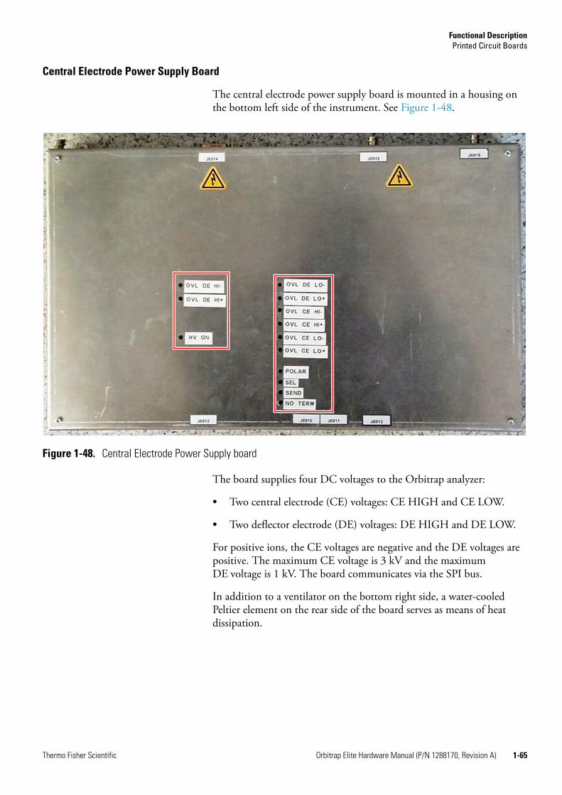
Functional DescriptionPrinted Circuit Boards
Thermo Fisher Scientific Orbitrap Elite Hardware Manual (P/N 1288170, Revision A) 1-65
Central Electrode Power Supply Board
The central electrode power supply board is mounted in a housing on the bottom left side of the instrument. See Figure 1-48.
The board supplies four DC voltages to the Orbitrap analyzer:
• Two central electrode (CE) voltages: CE HIGH and CE LOW.
• Two deflector electrode (DE) voltages: DE HIGH and DE LOW.
For positive ions, the CE voltages are negative and the DE voltages are positive. The maximum CE voltage is 3 kV and the maximum DE voltage is 1 kV. The board communicates via the SPI bus.
In addition to a ventilator on the bottom right side, a water-cooled Peltier element on the rear side of the board serves as means of heat dissipation.
Figure 1-48. Central Electrode Power Supply board
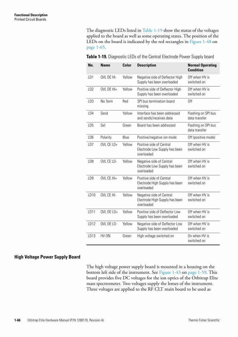
Functional DescriptionPrinted Circuit Boards
1-66 Orbitrap Elite Hardware Manual (P/N 1288170, Revision A) Thermo Fisher Scientific
The diagnostic LEDs listed in Table 1-19 show the status of the voltages applied to the board as well as some operating states. The position of the LEDs on the board is indicated by the red rectangles in Figure 1-48 on page 1-65.
High Voltage Power Supply Board
The high voltage power supply board is mounted in a housing on the bottom left side of the instrument. See Figure 1-43 on page 1-59. This board provides five DC voltages for the ion optics of the Orbitrap Elite mass spectrometer. Two voltages supply the lenses of the instrument. Three voltages are applied to the RF CLT main board to be used as
Table 1-19. Diagnostic LEDs of the Central Electrode Power Supply board
No. Name Color Description Normal OperatingCondition
LD1 OVL DE HI- Yellow Negative side of Deflector High Supply has been overloaded
Off when HV is switched on
LD2 OVL DE HI+ Yellow Positive side of Deflector High Supply has been overloaded
Off when HV is switched on
LD3 No Term Red SPI bus termination board missing
Off
LD4 Send Yellow Interface has been addressed and sends/receives data
Flashing on SPI bus data transfer
LD5 Sel Green Board has been addressed Flashing on SPI bus data transfer
LD6 Polarity Blue Positive/negative ion mode Off (positive mode)
LD7 OVL CE LO+ Yellow Positive side of Central Electrode Low Supply has been overloaded
Off when HV is switched on
LD8 OVL CE LO- Yellow Negative side of Central Electrode Low Supply has been overloaded
Off when HV is switched on
LD9 OVL CE HI+ Yellow Positive side of Central Electrode High Supply has been overloaded
Off when HV is switched on
LD10 OVL CE HI- Yellow Negative side of Central Electrode High Supply has been overloaded
Off when HV is switched on
LD11 OVL DE LO+ Yellow Positive side of Deflector Low Supply has been overloaded
Off when HV is switched on
LD12 OVL DE LO- Yellow Negative side of Deflector Low Supply has been overloaded
Off when HV is switched on
LD13 HV ON Green High voltage switched on On when HV is switched on

Functional DescriptionPrinted Circuit Boards
Thermo Fisher Scientific Orbitrap Elite Hardware Manual (P/N 1288170, Revision A) 1-67
focusing potentials for the curved linear trap. See “Orbitrap Analyzer” on page 1-14 for further information. The board communicates via the SPI bus.
The diagnostic LEDs listed in Table 1-20 on page 1-68 show the operating states of the board. The position of the LEDs on the board is indicated by the white rectangles in Figure 1-49.
Warning Electrical Shock Hazard. The high voltage power supply board creates voltages up to 3.5 kV! Shut down the instrument and disconnect it from line power before performing service.
Figure 1-49. High Voltage Power Supply board (cover removed)
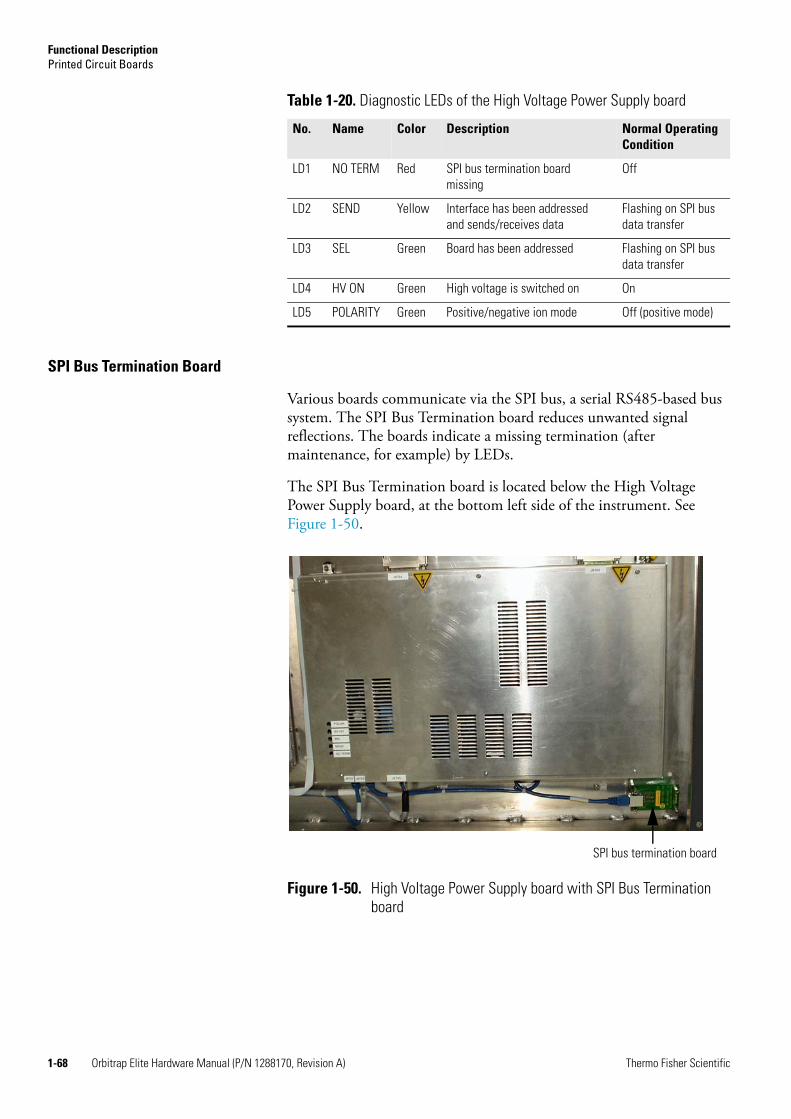
Functional DescriptionPrinted Circuit Boards
1-68 Orbitrap Elite Hardware Manual (P/N 1288170, Revision A) Thermo Fisher Scientific
SPI Bus Termination Board
Various boards communicate via the SPI bus, a serial RS485-based bus system. The SPI Bus Termination board reduces unwanted signal reflections. The boards indicate a missing termination (after maintenance, for example) by LEDs.
The SPI Bus Termination board is located below the High Voltage Power Supply board, at the bottom left side of the instrument. See Figure 1-50.
Table 1-20. Diagnostic LEDs of the High Voltage Power Supply board
No. Name Color Description Normal OperatingCondition
LD1 NO TERM Red SPI bus termination board missing
Off
LD2 SEND Yellow Interface has been addressed and sends/receives data
Flashing on SPI bus data transfer
LD3 SEL Green Board has been addressed Flashing on SPI bus data transfer
LD4 HV ON Green High voltage is switched on On
LD5 POLARITY Green Positive/negative ion mode Off (positive mode)
Figure 1-50. High Voltage Power Supply board with SPI Bus Termination board
SPI bus termination board
Thermo Fisher Scientific Orbitrap Elite Hardware Manual (P/N 1288170, Revision A) 2-1
Chapter 2 Basic System Operations
Many maintenance procedures for the Orbitrap Elite system require that the mass spectrometer be shut down. In addition, the Orbitrap Elite system can be placed in Standby condition if the system is not to be used for 12 hours or more.
The following topics are described in this chapter:
• “Shutting Down the System in an Emergency” on page 2-2
• “Placing the Instrument in Standby Condition” on page 2-4
• “Shutting Down the Orbitrap Elite Mass Spectrometer Completely” on page 2-7
• “Starting Up the System after a Shutdown” on page 2-9
• “Resetting the System” on page 2-12
• “Resetting Tune and Calibration Parameters to their Default Values” on page 2-13
• “Turning Off the Reagent Ion Source: What to Expect” on page 2-14

Basic System OperationsShutting Down the System in an Emergency
2-2 Orbitrap Elite Hardware Manual (P/N 1288170, Revision A) Thermo Fisher Scientific
Shutting Down the System in an EmergencyIf you need to turn off the mass spectrometer in an emergency, place the main power switch (located on the power panel at the right side of the Orbitrap Elite mass spectrometer) in the Off (0) position. This turns off all power to the instrument, including the linear ion trap, multiple socket outlets, and the vacuum pumps. The main power switch must be turned 90° anti-clockwise to switch off the instrument. See Figure 2-1.
The instrument is automatically vented by the vent valve of the linear ion trap. The vent valve vents the system 30 seconds after power is switched off.
Although removing power abruptly will not harm any component within the system, this is not the recommended shutdown procedure to follow. See “Shutting Down the Instrument” on page 2-7 for the recommended procedure.
Note To separately turn off the recirculating chiller or computer in an emergency, use the On/Off switches on the chiller and computer, respectively.
Behavior of the System in Case of a Main Failure
A main power failure has the same consequence as switching off via the main power switch. If the power is available again, the system starts up automatically: the pumps are switched on and the instrument is pumped down. If the system has been vented during the mains failure, it is necessary to bake out the system to obtain the operating vacuum. See “Baking Out the System” on page 3-4.
It is not possible to check whether the system was vented. The log file of the data system indicates a reboot of the system. In case of frequent but short power failures we recommend installing an uninterruptible power
Figure 2-1. Main power switch in Off position
On
Off

Basic System OperationsShutting Down the System in an Emergency
Thermo Fisher Scientific Orbitrap Elite Hardware Manual (P/N 1288170, Revision A) 2-3
supply (UPS). If main power failures occur frequently while the system is not attended (for example, in the night), we recommend installing a power fail detector.
Note The intentional venting of the system is performed with the vent valve of the linear ion trap.

Basic System OperationsPlacing the Instrument in Standby Condition
2-4 Orbitrap Elite Hardware Manual (P/N 1288170, Revision A) Thermo Fisher Scientific
Placing the Instrument in Standby ConditionThe Orbitrap Elite system should not be shut down completely if you are not going to use it for a short period of time, such as overnight or over the weekend. When you are not going to operate the system for 12 hours or more, you can leave the system in Standby condition.
In case of an Orbitrap Elite ETD mass spectrometer, first place the ETD Module in Standby condition. Then place the mass spectrometer in Standby condition according to the procedures described in the following topics.
Placing the ETD Module in Standby Condition
To place the ETD Module in Standby condition
1. If the Tune Plus window is not already open, choose Start > Programs > Thermo Instruments > LTQ > LTQ Tune from the taskbar. The Tune Plus window will open.
You can determine the state of the mass spectrometer by observing the state of the On/Off/Standby button on the Control/Scan Mode toolbar. See Figure 2-2. The three different states of the On/Standby button are shown at the left.
2. Click the Reagent Ion Source portion of the instrument control graphic at the top of the Tune Plus window. (See Figure 2-2.) The Reagent Ion Source dialog box appears. (See Figure 2-3.)
3. In the Reagent Ion Source dialog box, clear the Reagent Ion Source On box to place the Reagent Ion Source in Standby condition. See Figure 2-3 on page 2-5. This places the Reagent Ion Source in Standby condition as indicated by the Actual condition shown to the right of the Reagent Ion Source On box.
When the reagent ion source is placed in Standby condition, the filament and vial heaters turn off. Simultaneously, a valve opens to allow the nitrogen gas to cool the reagent vials. This cooling
Figure 2-2. Tune Plus window (Orbitrap Elite ETD), toolbar
On/Standby button Reagent Ion Source instrument control icon
On Off Standby

Basic System OperationsPlacing the Instrument in Standby Condition
Thermo Fisher Scientific Orbitrap Elite Hardware Manual (P/N 1288170, Revision A) 2-5
nitrogen runs until the reagent vials reach 70 °C. The audible rush (hissing noise) of nitrogen from the reagent ion source area in the back of the ETD Module is normal operation.
If the reagent ion source is on when you place the Orbitrap Elite ETD mass spectrometer in Standby mode, the filament turns off immediately. In contrast, the vial heaters stay on for 60 minutes before they turn off and the cooling gas begins. Because the filament is turned off, you can perform minor maintenance procedures on the ETD Module without cooling the reagent inlet.
More information about turning on and off the reagent heaters is given in “Reagent Heaters” on page 1-27.
Figure 2-3. Reagent Ion Source dialog box with Reagent Ion Source On box and Actual condition circled
Warning Burn Hazard. Install or exchange the reagent vials by following the procedure in “Replacing the Reagent Vials” on page 3-48. The reagent vials will be too hot to touch after the cooling nitrogen turns off at 70°C. Verify that the reagent vials are cool to the touch before handling them.

Basic System OperationsPlacing the Instrument in Standby Condition
2-6 Orbitrap Elite Hardware Manual (P/N 1288170, Revision A) Thermo Fisher Scientific
Placing the MS in Standby Condition
To place the Orbitrap Elite system in Standby condition
1. Wait until data acquisition, if any, is complete.
2. Turn off the flow of solvent from the LC (or other sample introduction device).
Note For instructions on how to operate the LC from the front panel, refer to the manual that came with the LC.
3. From the Tune Plus window, choose Control > Standby (or click on the On/Standby button to toggle it to Standby) to put the instrument in Standby condition. The consequences of this user action are described in the LTQ Series Hardware Manual. The System LED on the front panel of the Velos Pro mass spectrometer turns yellow when the system is in Standby condition.
4. Leave the LC power on.
5. Leave the autosampler power on.
6. Leave the data system power on.
7. Leave the Orbitrap Elite MS main power switch in the On position.
Warning Burn Hazard. The restrictor, the transfer line, and the ion source heater operate at 160 °C. Do not attempt to touch them unless the Orbitrap Elite mass spectrometer is shut down (See “Shutting Down the Orbitrap Elite Mass Spectrometer Completely” on page 2-7.) and these heaters have had sufficient time to cool down to room temperature.
On Off Standby

Basic System OperationsShutting Down the Orbitrap Elite Mass Spectrometer Completely
Thermo Fisher Scientific Orbitrap Elite Hardware Manual (P/N 1288170, Revision A) 2-7
Shutting Down the Orbitrap Elite Mass Spectrometer CompletelyThe Orbitrap Elite mass spectrometer does not need to be shut down completely if you are not going to use it for a short period of time, such as overnight or over weekends. Shut down ETD Module and MS system completely only if you do not want to use them for an extended period or if you want to perform a maintenance or service procedure.
To shut down the instrument completely
1. Place the ETD Module in Standby condition as described in “Placing the ETD Module in Standby Condition” on page 2-4.
2. Shut down the instrument as described in “Shutting Down the Instrument“ below. This also shuts down the ETD Module because its power controls are linked to the Orbitrap Elite MS power controls through the ETD Module Interface board. See “ETD Module Interface Board” on page 1-25.
Shutting Down the Instrument
To shut down the Orbitrap Elite system
1. Wait until data acquisition, if any, is complete.
2. Turn off the flow of solvent from the LC (or other sample introduction device).
Note For instructions on how to operate the LC from the front panel, refer to the manual that came with the LC.
3. From the Tune Plus window, choose Control > Off to put the instrument in Off condition. When you choose Control > Off, all high voltages are shut off, as are the flows of the sheath gas and the auxiliary gas.
4. Put the FT Electronics switch to the Off position. See Figure 1-7 on page 1-8.
5. Put the Vacuum Pumps switch to the Off position. See Figure 1-7. When you place the switch in the Off position, the following occurs:
a. All power to the instrument, including the turbomolecular pumps and the rotary-vane pumps, is turned off.
b. After 30 s, power to the vent valve solenoid of the ion trap is shut off. The vent valve opens and the vacuum manifold is vented with nitrogen to atmospheric pressure through a filter. You can hear a hissing sound as the gas passes through the filter.
Basic System OperationsShutting Down the Orbitrap Elite Mass Spectrometer Completely
2-8 Orbitrap Elite Hardware Manual (P/N 1288170, Revision A) Thermo Fisher Scientific
6. Leave the main power switch of the Orbitrap Elite mass spectrometer in the On position.
7. During service or maintenance operations that require opening the vacuum system of the Velos Pro MS or the Orbitrap Elite MS, always put the main switch (main circuit breaker) to the Off position. You can secure the main switch with a padlock or tie-wrap to prevent unintended re-powering.
Note If you are planning to perform routine or preventive system maintenance on the Orbitrap Elite mass spectrometer only, you do not need to turn off the recirculating chiller, LC, autosampler, or data system. In this case, the shutdown procedure is completed. However, if you do not plan to operate your system for an extended period of time, you might want to turn off the recirculating chiller, LC, autosampler, and data system.
Warning Burn Hazard. Allow heated components to cool down before you service them (the ion transfer tube is operated at about 300 °C, for example).
Basic System OperationsStarting Up the System after a Shutdown
Thermo Fisher Scientific Orbitrap Elite Hardware Manual (P/N 1288170, Revision A) 2-9
Starting Up the System after a ShutdownTo start up the Orbitrap Elite mass spectrometer after it has been shut down, you need to do the following:
1. Start up the instrument.
2. Set up conditions for operation.
Starting Up the Instrument
Note The recirculating chiller and data system must be running before you start up the instrument. The instrument will not operate until it has established a communication link to the data system.
To start up the Orbitrap Elite mass spectrometer
1. Start up the (optional) LC and autosampler as is described in the manual that came with the LC and autosampler.
2. Start up the data system and the chiller.
3. Turn on the flows of helium and nitrogen at the tanks, if they are off.
4. Make sure that the main power switch of the Velos Pro MS is in the On position and the electronics service switch of the Velos Pro MS is in the Operating position.
5. Place the main power switch at the right side of the Orbitrap Elite mass spectrometer in the On position.
6. Put the Vacuum Pumps switch to the On position. See Figure 1-7 on page 1-8. The rotary-vane pumps and the turbomolecular pumps are started.
Note Pumping the system after a complete shut down takes hours and requires overnight baking of the system.
7. Put the FT Electronics switch to the On position. See Figure 1-7. When you place the FT Electronics switch to the On position, the following occurs:
a. Power is provided to all electronic boards. (The electron multiplier, conversion dynode, 8 kV power to the API source, main RF voltage, and quadrupole RF voltage remain off.)
b. The internal computer reboots. After several seconds, the Communication LED on the front panel turns yellow to
Basic System OperationsStarting Up the System after a Shutdown
2-10 Orbitrap Elite Hardware Manual (P/N 1288170, Revision A) Thermo Fisher Scientific
indicate that the data system has started to establish a communication link.
c. After several more seconds, the Communication LED turns green to indicate that the data system has established a communication link. Software for the operation of the instrument is then transferred from the data system to the instrument.
d. After three minutes, the System LED of the ion trap turns yellow to indicate that the software transfer from the data system is complete and that the instrument is in Standby condition.
Note The Vacuum LED on the front panel of the Velos Pro turns green only if the pressure in the vacuum manifold is below the maximum allowable pressure (5×10⁻⁴ Torr in the analyzer region, and 2 Torr in the S-lens region), and the safety interlock switch on the API source is pressed down (that is, the API flange is secured to the spray shield).
8. Press the Reset button on the Velos Pro to establish the communication link between Velos Pro and internal computer.
If you have an LC or autosampler, start it as is described in the manual that came with the LC or autosampler. Then, proceed to “Setting Up Conditions for Operation“. If you do not have either, go to the topic directly.
Setting Up Conditions for Operation
To set up your Orbitrap Elite mass spectrometer for operation
1. Before you begin data acquisition with your Orbitrap Elite system, you need to allow the system to pump down for at least eight hours. Operation of the system with excessive air and water in the vacuum manifold can cause reduced sensitivity, tuning problems, and a reduced lifetime of the electron multiplier.
Note The vacuum in the analyzer system can be improved by an overnight baking of the system. See “Baking Out the System” on page 3-4.
2. Ensure that the gas pressures are within the operational limits:
• Helium: 275 ± 70 kPa (2.75 ± 0.7 bar, 40 ±10 psi),
• Nitrogen: 690 ± 140 kPa (6.9 ± 1.4 bar, 100 ± 20 psi).

Basic System OperationsStarting Up the System after a Shutdown
Thermo Fisher Scientific Orbitrap Elite Hardware Manual (P/N 1288170, Revision A) 2-11
In case of an Orbitrap Elite ETD mass spectrometer, also check the pressure of the reagent carrier gas: 690 ± 140 kPa (6.9 ± 1.4 bar, 100 ± 20 psi).
Note Air in the helium line must be purged or given sufficient time to be purged for normal performance.
3. Click the Display Status View button in the Tune Plus window. Check whether the pressure measured by the ion gauge is ≤5 × 10⁻⁹ mbar, and the pressure measured by the Pirani gauge is around 1 mbar. Compare the values of the other parameters in the status panel with values that you recorded previously.
4. In case of an Orbitrap Elite ETD mass spectrometer, start up the ETD Module as described in “Starting the ETD Module After a Complete Shutdown“. In case of an Orbitrap Elite mass spectrometer, continue to set up for ESI or APCI operation as described in Orbitrap Elite Getting Started.
Starting the ETD Module After a Complete Shutdown
To start up the ETD Module after a complete shutdown
1. Start the Orbitrap Elite ETD mass spectrometer according to the start up procedures given in “Starting Up the System after a Shutdown“ above. This also turns on the ETD Module as the ETD Module power controls are linked to the MS power controls (see “ETD Module Interface Board” on page 1-25).
2. If the Tune Plus window is not already open, choose Start > Programs > Thermo Instruments > LTQ > LTQ Tune from the taskbar. The Tune plus window will open.
You can determine the state of the MS detector by observing the state of the On/Off/Standby button on the Control/Scan Mode toolbar. (See Figure 2-2 on page 2-4.) The three different states of the On/Standby button are shown at the left.
3. Click the Display Status View button in the Tune Plus window.
Check the reagent vacuum parameters:
• Reagent ion gauge pressure: 20 to 35 × 10-5 Torr
• Reagent Convectron gauge pressure: <0.08 Torr
• Reagent turbomolecular pump speed : > 90%
4. Continue to set up the instrument for operation as described in Orbitrap Elite Getting Started manual.
On Off Standby

Basic System OperationsResetting the System
2-12 Orbitrap Elite Hardware Manual (P/N 1288170, Revision A) Thermo Fisher Scientific
Resetting the SystemIf the communication link between Orbitrap Elite mass spectrometer and data system computer is lost, it may be necessary to reset the system using the Reset button of the Velos Pro mass spectrometer.
The procedure given here assumes that the Orbitrap Elite mass spectrometer and data system computer are both powered on and are operational. If the instrument, data system computer, or both are off, see “Starting Up the System after a Shutdown” on page 2-9.
To reset the Orbitrap Elite mass spectrometer, press the Reset button of the Velos Pro. See the LTQ Series Hardware Manual for the location of the Reset button. When you press the Reset button, the following occurs:
1. An interrupt on the mainboard of the internal computer causes the internal computer to reboot. All LEDs on the front panel are off except the Power LED.
2. After several seconds, the Communication LED turns yellow to indicate that the data system and the instrument are starting to establish a communication link.
3. After several more seconds, the Communication LED turns green to indicate that the data system and the instrument have established a communication link. Software for the operation of the instrument is then transferred from the data system to the instrument.
4. After three min, the software transfer is complete. The System LED turns either green to indicate that the instrument is functional and the high voltages are on or yellow to indicate that the instrument is functional and it is in Standby condition.

Basic System OperationsResetting Tune and Calibration Parameters to their Default Values
Thermo Fisher Scientific Orbitrap Elite Hardware Manual (P/N 1288170, Revision A) 2-13
Resetting Tune and Calibration Parameters to their Default ValuesYou can reset the Orbitrap Elite system tune and calibration parameters to their default values at any time. This feature may be useful if you have manually set some parameters that have resulted in less than optimum performance.
To reset the Orbitrap Elite MS tune and calibration parameters
In the Tune Plus window,
• Choose File > Restore Factory Calibration to restore the default calibration parameters, or
• Choose File > Restore Factory Tune Method to restore the default tune parameters.
Note Make sure that any problems you might be experiencing are not due to improper API source settings (spray voltage, sheath and auxiliary gas flow, ion transfer capillary temperature, etc.) before resetting the system parameters to their default values.
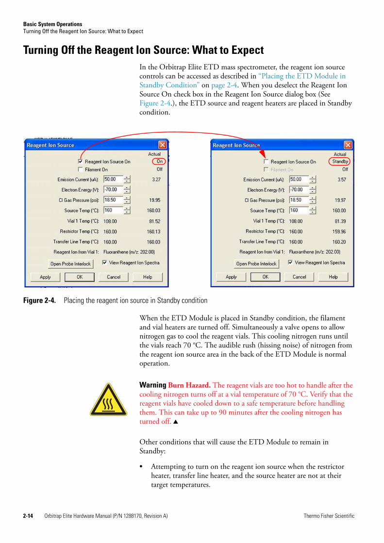
Basic System OperationsTurning Off the Reagent Ion Source: What to Expect
2-14 Orbitrap Elite Hardware Manual (P/N 1288170, Revision A) Thermo Fisher Scientific
Turning Off the Reagent Ion Source: What to ExpectIn the Orbitrap Elite ETD mass spectrometer, the reagent ion source controls can be accessed as described in “Placing the ETD Module in Standby Condition” on page 2-4. When you deselect the Reagent Ion Source On check box in the Reagent Ion Source dialog box (See Figure 2-4.), the ETD source and reagent heaters are placed in Standby condition.
When the ETD Module is placed in Standby condition, the filament and vial heaters are turned off. Simultaneously a valve opens to allow nitrogen gas to cool the reagent vials. This cooling nitrogen runs until the vials reach 70 °C. The audible rush (hissing noise) of nitrogen from the reagent ion source area in the back of the ETD Module is normal operation.
Other conditions that will cause the ETD Module to remain in Standby:
• Attempting to turn on the reagent ion source when the restrictor heater, transfer line heater, and the source heater are not at their target temperatures.
Figure 2-4. Placing the reagent ion source in Standby condition
Warning Burn Hazard. The reagent vials are too hot to handle after the cooling nitrogen turns off at a vial temperature of 70 °C. Verify that the reagent vials have cooled down to a safe temperature before handling them. This can take up to 90 minutes after the cooling nitrogen has turned off.
Basic System OperationsTurning Off the Reagent Ion Source: What to Expect
Thermo Fisher Scientific Orbitrap Elite Hardware Manual (P/N 1288170, Revision A) 2-15
• Whenever either the mass spectrometer or the ETD Module goes into Standby mode. Reagent vial nitrogen cooling will turn on if the vials are at an elevated temperature.
Exception: If the Orbitrap Elite ETD mass spectrometer is placed in Standby by clicking the Standby button in Tune Plus (see Standby icon in the margin), there is an hour delay before the cooling nitrogen turns on.
• Whenever the pressure in the mass spectrometer or the ETD Module exceeds its protection limit. Reagent vial nitrogen cooling will turn on if the vials are at an elevated temperature.
• Whenever the abundance of reagent ions becomes insufficient as determined by the AGC setting. When this occurs, the Orbitrap Elite ETD mass spectrometer completes the Xcalibur Sequence step in progress before going into Standby mode.

Thermo Fisher Scientific Orbitrap Elite Hardware Manual (P/N 1288170, Revision A) 3-1
Chapter 3 User Maintenance
This chapter describes routine maintenance procedures that must be performed to ensure optimum performance of the Orbitrap Elite mass spectrometer.
For instructions on maintaining the Velos Pro linear trap, refer to the LTQ Series Hardware Manual. For instructions on maintaining LCs or autosamplers, refer to the manual that comes with the LC or autosampler.
Note It is the user’s responsibility to maintain the system properly by performing the system maintenance procedures on a regular basis.
The following topics are described in this chapter:
• “General Remarks” on page 3-2
• “Baking Out the System” on page 3-4
• “Maintenance of the Vacuum System” on page 3-4
• “Maintenance of the ETD Module” on page 3-12
• “Maintenance of the Cooling Circuit” on page 3-58
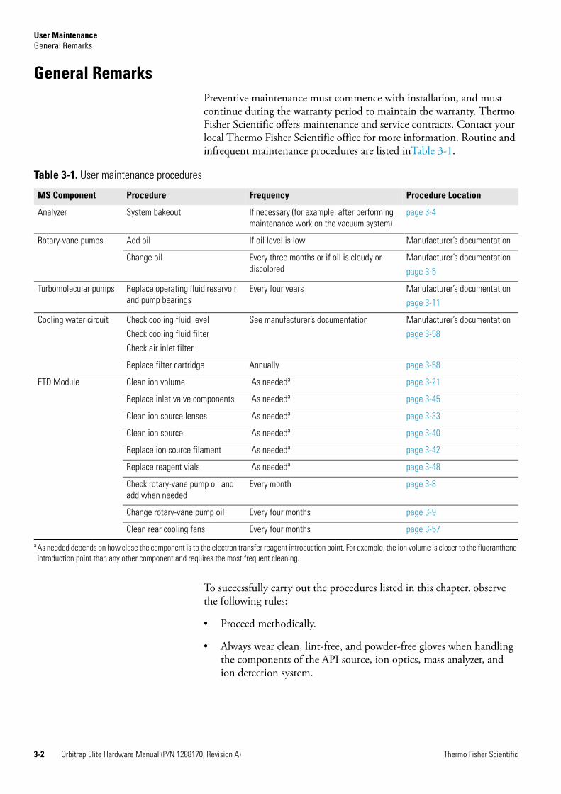
User MaintenanceGeneral Remarks
3-2 Orbitrap Elite Hardware Manual (P/N 1288170, Revision A) Thermo Fisher Scientific
General RemarksPreventive maintenance must commence with installation, and must continue during the warranty period to maintain the warranty. Thermo Fisher Scientific offers maintenance and service contracts. Contact your local Thermo Fisher Scientific office for more information. Routine and infrequent maintenance procedures are listed inTable 3-1.
To successfully carry out the procedures listed in this chapter, observe the following rules:
• Proceed methodically.
• Always wear clean, lint-free, and powder-free gloves when handling the components of the API source, ion optics, mass analyzer, and ion detection system.
Table 3-1. User maintenance procedures
MS Component Procedure Frequency Procedure Location
Analyzer System bakeout If necessary (for example, after performing maintenance work on the vacuum system)
page 3-4
Rotary-vane pumps Add oil If oil level is low Manufacturer’s documentation
Change oil Every three months or if oil is cloudy or discolored
Manufacturer’s documentation
page 3-5
Turbomolecular pumps Replace operating fluid reservoir and pump bearings
Every four years Manufacturer’s documentation
page 3-11
Cooling water circuit Check cooling fluid level
Check cooling fluid filter
Check air inlet filter
See manufacturer’s documentation Manufacturer’s documentation
page 3-58
Replace filter cartridge Annually page 3-58
ETD Module Clean ion volume As neededa page 3-21
Replace inlet valve components As neededa page 3-45
Clean ion source lenses As neededa page 3-33
Clean ion source As neededa page 3-40
Replace ion source filament As neededa page 3-42
Replace reagent vials As neededa page 3-48
Check rotary-vane pump oil and add when needed
Every month page 3-8
Change rotary-vane pump oil Every four months page 3-9
Clean rear cooling fans Every four months page 3-57
a As needed depends on how close the component is to the electron transfer reagent introduction point. For example, the ion volume is closer to the fluoranthene introduction point than any other component and requires the most frequent cleaning.

User MaintenanceGeneral Remarks
Thermo Fisher Scientific Orbitrap Elite Hardware Manual (P/N 1288170, Revision A) 3-3
Thermo Fisher Scientific recommends the following gloves: white nitrile clean room gloves (Fisher Scientific P/N 19-120-2947B [size medium] or P/N 19-120-2947C [size large]; Thermo Scientific P/N 23827-0008) [size medium] or P/N 23827-0009 [size large]).
• Never re-use gloves after you remove them because the surface contaminants on them will re-contaminate clean parts.
• Always wear protective eye wear when you clean parts.
• Always place the components on a clean, lint-free, and powder-free surface.
• Always cover the opening in the top of the vacuum manifold with a large, lint-free tissue whenever you remove the top cover plate of the vacuum manifold.
• Never overtighten a screw or use excessive force.
• Dirty tools can contaminate your system. Keep the tools clean and use them exclusively for maintenance and service work at the Orbitrap Elite mass spectrometer.
• Never insert a test probe (for example, an oscilloscope probe) into the sockets of female cable connectors on PCBs.
Returning Parts
To protect our employees, we ask you for some special precautions when returning parts for exchange or repair to the factory. Your signature on the Repair Covering letter confirms that the returned parts have been de-contaminated and are free of hazardous materials. See ”Safety Advice for Possible Contamination” on page viii for further information.
Cleaning the Surface of the Instrument
Clean the outside of the instrument with a dry cloth. For removing stains or fingerprints on the surface of the instrument (panels, for example), slightly dampen the cloth (preferably made of microfiber) with distilled water.
Caution Prevent any liquids from entering the inside of the instrument.
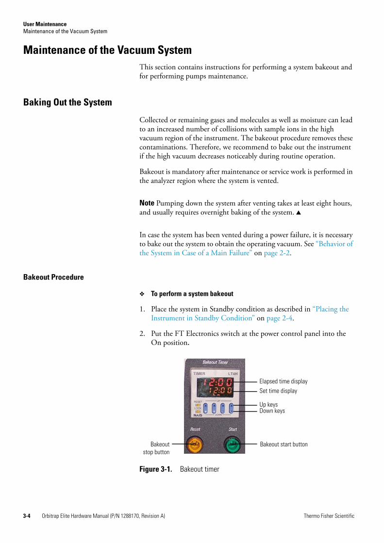
User MaintenanceMaintenance of the Vacuum System
3-4 Orbitrap Elite Hardware Manual (P/N 1288170, Revision A) Thermo Fisher Scientific
Maintenance of the Vacuum SystemThis section contains instructions for performing a system bakeout and for performing pumps maintenance.
Baking Out the System
Collected or remaining gases and molecules as well as moisture can lead to an increased number of collisions with sample ions in the high vacuum region of the instrument. The bakeout procedure removes these contaminations. Therefore, we recommend to bake out the instrument if the high vacuum decreases noticeably during routine operation.
Bakeout is mandatory after maintenance or service work is performed in the analyzer region where the system is vented.
Note Pumping down the system after venting takes at least eight hours, and usually requires overnight baking of the system.
In case the system has been vented during a power failure, it is necessary to bake out the system to obtain the operating vacuum. See “Behavior of the System in Case of a Main Failure” on page 2-2.
Bakeout Procedure
To perform a system bakeout
1. Place the system in Standby condition as described in “Placing the Instrument in Standby Condition” on page 2-4.
2. Put the FT Electronics switch at the power control panel into the On position.
Figure 3-1. Bakeout timer
Elapsed time display
Down keysUp keys
Set time display
Bakeout start buttonBakeoutstop button

User MaintenanceMaintenance of the Vacuum System
Thermo Fisher Scientific Orbitrap Elite Hardware Manual (P/N 1288170, Revision A) 3-5
3. Set the bakeout time by entering the desired time (hh:mm) with the up/down keys of the bakeout timer. See Figure 3-1 on page 3-4.
4. Start the bakeout procedure by pressing the green start button on the right. The Orbitrap Elite mass spectrometer indicates a running bakeout procedure by the flashing Vacuum and System LEDs on the front side of the instrument. See Figure 1-4 on page 1-5.
You can stop a running bakeout procedure by pressing the orange reset/stop button on the left side. Also press this button after you have changed the preset bakeout time.
5. The bakeout procedure is terminated because of two reasons:
• The preset duration has expired, or
• The vacuum has risen above a preset value.
The termination of the baking process is indicated by the status LEDs (System and Vacuum) on the front side that have stopped flashing.
Maintenance of the Forepumps
Rotary-vane pumps require minimal maintenance. All that is required to maintain the rotary-vane pump is to inspect, add, purge, and change the pump oil.
For maintenance of the forepumps of the MS portion, refer to the LTQ Series Hardware Manual or the pump manufacturer’s manual.
Note The manuals of the pump manufacturers give detailed advice regarding safety, operation, maintenance, and installation. Please note the warnings and precautions contained in these manuals!
Maintenance of the ETD Forepump
Rotary-vane pump oil (P/N A0301-15101) is a translucent light amber color and it should be checked often. During normal operation, oil must always be visible in the oil level sight glass between the MIN and MAX marks. If the oil level is below the MIN mark, add oil. If the oil is cloudy or discolored, purge the oil to decontaminate dissolved solvents. If the pump oil is still discolored, change it. You should change the pump oil every 3000 hours (about four months) of operation.
The rotary-vane pump major components are shown in Figure 3-2 on page 3-6.
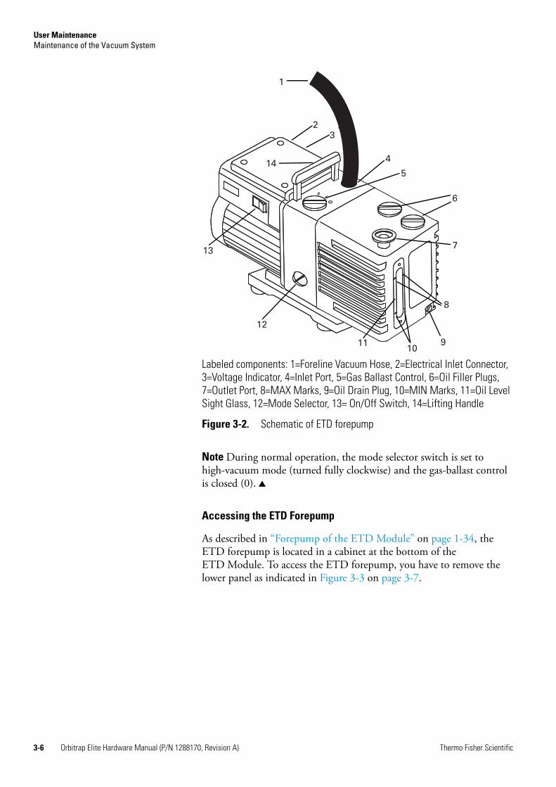
User MaintenanceMaintenance of the Vacuum System
3-6 Orbitrap Elite Hardware Manual (P/N 1288170, Revision A) Thermo Fisher Scientific
Note During normal operation, the mode selector switch is set to high-vacuum mode (turned fully clockwise) and the gas-ballast control is closed (0).
Accessing the ETD Forepump
As described in “Forepump of the ETD Module” on page 1-34, the ETD forepump is located in a cabinet at the bottom of the ETD Module. To access the ETD forepump, you have to remove the lower panel as indicated in Figure 3-3 on page 3-7.
Labeled components: 1=Foreline Vacuum Hose, 2=Electrical Inlet Connector, 3=Voltage Indicator, 4=Inlet Port, 5=Gas Ballast Control, 6=Oil Filler Plugs, 7=Outlet Port, 8=MAX Marks, 9=Oil Drain Plug, 10=MIN Marks, 11=Oil Level Sight Glass, 12=Mode Selector, 13= On/Off Switch, 14=Lifting Handle
Figure 3-2. Schematic of ETD forepump
3
1
23
4
5
6
7
8
91011
12
13
14

User MaintenanceMaintenance of the Vacuum System
Thermo Fisher Scientific Orbitrap Elite Hardware Manual (P/N 1288170, Revision A) 3-7
Two pairs of hooks under the top panel hold the bottom panel. They mount into corresponding openings at the top side of the bottom panel. Figure 3-4 shows the details for the right side of the instrument. The panel hangs on the hooks and comes off if lifted up a little and getting pulled on into the backwards direction.
On the bottom of the rear side of the MS portion, two Allen screws fix the panel to the instrument frame by means of fork-like extensions (lugs). See Figure 3-5 on page 3-8.
Figure 3-3. Accessing the ETD Forepump: Removing the panel
Pull to remove panel
Loosen screws on both sides
Figure 3-4. Hooks (left) and top side of detached bottom panel (right)
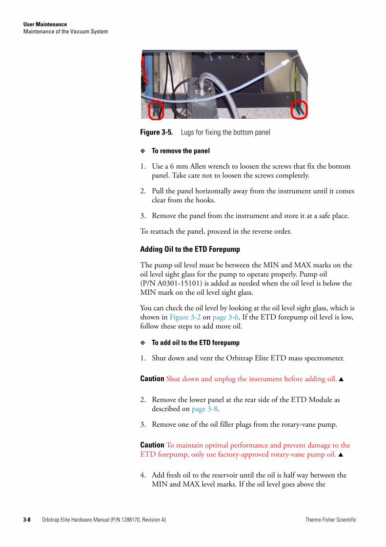
User MaintenanceMaintenance of the Vacuum System
3-8 Orbitrap Elite Hardware Manual (P/N 1288170, Revision A) Thermo Fisher Scientific
To remove the panel
1. Use a 6 mm Allen wrench to loosen the screws that fix the bottom panel. Take care not to loosen the screws completely.
2. Pull the panel horizontally away from the instrument until it comes clear from the hooks.
3. Remove the panel from the instrument and store it at a safe place.
To reattach the panel, proceed in the reverse order.
Adding Oil to the ETD Forepump
The pump oil level must be between the MIN and MAX marks on the oil level sight glass for the pump to operate properly. Pump oil (P/N A0301-15101) is added as needed when the oil level is below the MIN mark on the oil level sight glass.
You can check the oil level by looking at the oil level sight glass, which is shown in Figure 3-2 on page 3-6. If the ETD forepump oil level is low, follow these steps to add more oil.
To add oil to the ETD forepump
1. Shut down and vent the Orbitrap Elite ETD mass spectrometer.
Caution Shut down and unplug the instrument before adding oil.
2. Remove the lower panel at the rear side of the ETD Module as described on page 3-8.
3. Remove one of the oil filler plugs from the rotary-vane pump.
Caution To maintain optimal performance and prevent damage to the ETD forepump, only use factory-approved rotary-vane pump oil.
4. Add fresh oil to the reservoir until the oil is half way between the MIN and MAX level marks. If the oil level goes above the
Figure 3-5. Lugs for fixing the bottom panel

User MaintenanceMaintenance of the Vacuum System
Thermo Fisher Scientific Orbitrap Elite Hardware Manual (P/N 1288170, Revision A) 3-9
MAX level mark, remove the drain plug and drain the excess oil into a suitable container.
5. Insert the oil filler plug back into the rotary-vane pump.
6. Reattach the lower panel at the rear side of the ETD Module.
7. Plug in the instrument.
8. Restart the system.
Purging the Rotary-Vane Pump Oil
When the rotary-vane pump oil becomes cloudy or discolored, purge the oil. Purging (or decontaminating) the oil removes dissolved gases and low boiling-point liquids. You can purge the oil without interrupting system operation, but do not purge it during an acquisition or while the electron multiplier or filament is powered on.
To purge the rotary-vane pump oil
1. Remove the lower panel at the rear side of the ETD Module as described on page 3-8.
2. Set the gas ballast control (See Figure 3-2 on page 3-6.) to Low Flow (I).
3. Operate the pump for 10 minutes or until the oil is clear. If the oil remains cloudy or discolored after 10 minutes, replace the oil.
4. Set the gas ballast control to Closed (0), as shown in Figure 3-6.
5. Reattach the lower panel at the rear side of the ETD Module.
Changing the Rotary-Vane Pump Oil
You should change the ETD forepump oil every four months (about 3000 hours of operation).
Supplies needed for changing the ETD forepump oil:
• Rotary-vane pump oil (P/N A0301-15101)
• Suitable container for removing spent or excess oil
Figure 3-6. Gas ballast control positions
High Flow (Position II)
Low Flow (Position I)
Closed (Position 0)

User MaintenanceMaintenance of the Vacuum System
3-10 Orbitrap Elite Hardware Manual (P/N 1288170, Revision A) Thermo Fisher Scientific
Note For best results, change the oil while the ETD forepump is still warm after operation. Be careful, however, as the oil can still be very hot at this time.
To change the ETD forepump oil
1. Shut down and vent the Orbitrap Elite ETD mass spectrometer.
Caution Shut down and unplug the instrument before adding oil.
2. Remove the lower panel at the rear side of the ETD Module as described on page 3-8.
3. Disassemble the rotary-vane pump.
a. Disconnect the foreline vacuum hose. (See Figure 3-2 on page 3-6.)
b. Disconnect the exhaust vacuum hose.
c. Place the rotary-vane pump on a bench.
4. Drain the spent oil.
a. Remove one of the oil filler plugs.
b. Remove the oil drain plug and allow the oil to drain into a suitable container.
c. Dispose of the spent oil according to local environmental regulations.
d. Replace the oil drain plug.
5. Add fresh oil.
a. Add oil into oil filler reservoir half way between the MIN and MAX level marks.
b. If the oil level goes above the MAX level mark, remove the drain plug and drain the excess oil from the pump.
Warning Burn Hazard. Handle hot pump oil carefully to avoid being burned or injured.
Warning Lifting Hazard. Use the proper lifting technique to lift the ETD forepump. It weighs approximately 23 kg (50 lb).

User MaintenanceMaintenance of the Vacuum System
Thermo Fisher Scientific Orbitrap Elite Hardware Manual (P/N 1288170, Revision A) 3-11
6. Reassemble the rotary-vane pump.
a. Replace the oil filler plug.
b. Return the rotary-vane pump to the floor.
c. Reconnect the foreline vacuum hose to the rotary-vane pump.
d. Reconnect the exhaust vacuum hose to the rotary-vane pump.
e. Plug in the rotary-vane pump.
7. Reattach the lower panel at the rear side of the ETD Module.
8. Plug in the instrument.
9. Restart the system.
Maintenance of the Turbomolecular Pumps
The turbomolecular pumps in the MS portion of the Orbitrap Elite mass spectrometer need maintenance work by the user that is briefly outlined below. In contrast, the turbomolecular pump in the ETD Module of the Orbitrap Elite ETD mass spectrometer contains no user-serviceable parts.
Note The manuals of the pump manufacturers give detailed advice regarding safety, operation, maintenance, and installation. Please note the warnings and cautions contained in these manuals!
Replacing the Operating Fluid Reservoir of the Turbomolecular Pumps
The manufacturer recommends replacing the operating fluid reservoirs of the turbomolecular pumps at least every four years. The storage stability of the operating fluid is limited. The specification of durability is given by the pump manufacturer. The disposal of used oil is subject to the relevant regulations.
Replacements for the operating fluid reservoirs including Porex rods (HiPace™ 80: P/N 1275740; HiPace™ 300: P/N 1275730) are available from Thermo Fisher Scientific.
Note The pump bearings have also to be replaced at least every four years. This maintenance operation requires special training and additional equipment. Therefore, Thermo Fisher Scientific recommends calling a Thermo Fisher Scientific field service engineer to replace both the operating fluid reservoir and the pump bearings.

User MaintenanceMaintenance of the ETD Module
3-12 Orbitrap Elite Hardware Manual (P/N 1288170, Revision A) Thermo Fisher Scientific
Maintenance of the ETD ModuleThis section describes routine ETD Module maintenance procedures that must be carried out to ensure optimum performance of the system. Some of the procedures describe how to clean components of the ETD Module. Others involve replacing components or replenishing the electron transfer reagent. See also the ETD Module Hardware Manual for additional information.
Figure 3-7 illustrates the sequence in which to perform routine maintenance on the ETD system.
Table 3-2 on page 3-13 gives advice for correcting frequent problems with the ETD system.
Figure 3-7. Routine maintenance sequence for ETD system
RemoveIon Volume
CleanIon Volume
Yes
No
Yes
No No
Yes
RemoveVacuum Manifold
Cover
ReplaceIon Volume
CleanIon Source
Lenses?
RemoveLenses
CleanLenses
ReinstallReagent Ion Source
ReinstallLenses
RemoveIon Source from
Vacuum Manifold
ReinstallETD Module
Covers
Start UpMS/ETD System
ReplaceVacuum Manifold
Cover
End
CleanReagent Ion Source
Block Assembly?
RemoveReagent Ion Source
Block Assembly
CleanRemaining
Reagent Ion SourceComponents
?
CleanReagent Ion Source
Block Assembly
ReassembleReagent Ion Source
Block Assembly
ReinstallReagent Ion Source
Block Assembly
DisassembleReagent Ion Source
Block Assembly DisassembleRemaining
Reagent Ion SourceComponents
ReassembleRemaining
Reagent Ion SourceComponents
CleanRemaining
Reagent Ion SourceComponents
VentMS/ETD System
RemoveETD Module
Covers
Start

User MaintenanceMaintenance of the ETD Module
Thermo Fisher Scientific Orbitrap Elite Hardware Manual (P/N 1288170, Revision A) 3-13
Handling and Cleaning Reagent Ion Source Parts
A large part of maintaining your reagent ion source consists of making sure that all the components are clean. Use the cleaning procedures listed in this section to clean stainless steel and non-stainless steel parts. However, use caution when doing so, because some components can be damaged by exposure to liquids.
How often you clean the reagent ion source depends on the amount of reagent introduced into the system. In general, the closer a component is to where the reagent ion is introduced, the more rapidly it becomes dirty (see the footnote in Table 3-1 on page 3-2). For example, the ion volume needs to be cleaned more often than other parts.
Many parts can be removed and disassembled by hand. Make sure you have all the necessary tools before carrying out a procedure. See below for a list of the tools and supplies generally needed for maintenance of the reagent ion source. Tools should be used only for the maintenance of the reagent ion source and be free of grease or other residues. Handle parts in a manner that maintains their cleanliness.
Note It is crucial that the cleanliness of the parts be maintained when they are handled. Wear gloves and place the parts on surfaces that are clean if the parts are not returned directly to the instrument. If clean surfaces are not available, place the parts on fresh lint free wipes or cloths or aluminum foil that has not been used for any other purpose.
Table 3-2. Indications requiring maintenance of the ETD system
Symptom Cause Fix
No ions at m/z 202 with the emission current at the correct level.
The m/z 202 is outside the mass range. Set the starting mass lower.
The m/z 202 signal intensity drops slowly over several days when the emission current is at the correct level.
The ion volume needs to be cleaned or replaced. Clean or replace the ion volume when the injection time is over 100 ms. See page 3-21.
A system error message advising that the maximum injection time has been reached for the ETD AGC.
The AGC target has not been reached within the specified time limit. The ion volume needs to be cleaned or replaced.
Clean the ion volume. Increase the maximum injection time limit.
Sudden and complete drop of m/z 202 level, low emission current.
The filament may just have blown out. Check the filament. Replace it if necessary. See page 3-42.
User MaintenanceMaintenance of the ETD Module
3-14 Orbitrap Elite Hardware Manual (P/N 1288170, Revision A) Thermo Fisher Scientific
The following tools and supplies are needed for reagent ion source maintenance:
• Clean, dry gas (air or nitrogen)
• New, white nitrile clean room gloves (Fisher Scientific P/N 19-120-2947B [size medium] or P/N 19-120-2947C [size large]; Thermo Scientific P/N 23827-0008 ) [size medium] or P/N 23827-0009 [size large])
• Lint-free cloth or paper
• Nut driver, 5.5 mm
• Protective eyewear
• Screwdriver, Phillips #2
• Screwdriver, flat blade
• Wrench, adjustable
• Wrench, Allen, 2 mm, 2.5 mm, 3 mm, 4 mm, 5/32-in., 5/64-in., 1/16-in
• Wrench, open-ended, 1/4-in., 5/16-in., 7/16-in. (2), 1/2-in., 9/16-in.
• Wrench, socket, 1/2-in.
Cleaning Stainless Steel Parts
The reagent ion source, ion volume assembly, ion source block, and lenses are made from stainless steel. To clean these parts, follow the procedure described in this topic. Use this procedure with caution because some components can be damaged when exposed to liquids.
The following tools and supplies are needed for cleaning stainless steel parts in the reagent ion source:
• Acetone, analytical grade (or other suitable solvent)
• Aluminum oxide abrasive, number 600 (P/N 32000-60340)
• Applicators, cotton-tipped
• Beaker, 450 mL
• Clean, dry gas
• De-ionized water
• Detergent (Alconox®, Micro, or equivalent)
• Dremel® rotary tool or equivalent (recommended)

User MaintenanceMaintenance of the ETD Module
Thermo Fisher Scientific Orbitrap Elite Hardware Manual (P/N 1288170, Revision A) 3-15
• Foil, aluminum
• Forceps
• New, white nitrile clean room gloves
• Glycerol, reagent grade
• Lint-free cloth
• Protective eyewear
• Tap water
• Toothbrush, soft
• Ultrasonic cleaner
Caution Do not use this procedure to clean ceramic, aluminum, or gold plated parts. See page 3-17 for the method for cleaning ceramic, aluminum, or gold plated parts.
Caution Follow the subsequent instructions precisely. If done wrong, the cleaning procedure could damage the ion source lenses.
To clean reagent ion source stainless steel parts
1. Remove contamination from the surfaces being cleaned.
a. Use a slurry of number 600 aluminum oxide in glycerol and a cleaning brush or cotton-tipped applicator. Contamination often appears as dark or discolored areas, but may not be visible. The heaviest contamination is usually found around the apertures, such as the electron entrance hole on the ion volume.
b. Clean each part thoroughly, even if no contamination is visible.
c. Use the wooden end of an applicator that is cut at an angle to clean the inside corners.
d. Use a Dremel® tool with the polishing swab at its lowest speed. This will increase the cleaning efficiency and decrease the time required to clean the part.
Warning Hand and Eye Hazard. Wear impermeable laboratory gloves and eye protection when performing these cleaning procedures.
User MaintenanceMaintenance of the ETD Module
3-16 Orbitrap Elite Hardware Manual (P/N 1288170, Revision A) Thermo Fisher Scientific
2. Rinse the parts with clean water.
3. Use a clean applicator or toothbrush to remove the aluminum oxide slurry. Do not let the slurry dry on the metal because dried aluminum oxide is difficult to remove.
4. Place the parts in a warm detergent solution in an ultrasonic bath and sonicate them.
a. Make a solution of detergent and warm tap water in a 400 mL glass beaker.
b. Using forceps, place the parts in a beaker containing the warm detergent solution.
c. Place the beaker and contents in an ultrasonic bath for five minutes.
d. Rinse the parts with tap water to remove the detergent.
5. Sonicate the parts in deionized water.
a. Using forceps, place the parts in a beaker containing deionized water.
b. Place the beaker and contents in an ultrasonic bath for five minutes.
c. If the water is cloudy after sonicating, pour off the water, add fresh water, and place the beaker and its contents in a ultrasonic bath again for five minutes. Repeat until the water is clear.
6. Sonicate the parts in acetone.
a. Using forceps, place the parts in a beaker containing fresh acetone.
b. Place the beaker and contents in an ultrasonic bath again for five minutes.
7. Blow-dry the parts immediately. Use clean, dry gas (air or nitrogen) to blow the acetone off the parts.
8. Complete the drying process, doing one of the following:
• Using forceps, place the parts in a 500 mL glass beaker, cover the beaker with aluminum foil, and put the beaker in an oven set at 100 °C for 30 minutes.
Warning Injury Hazard. To prevent personal injury, be sure to keep the Dremel tool away from possible hazards, such as standing water or flammable solvents.
User MaintenanceMaintenance of the ETD Module
Thermo Fisher Scientific Orbitrap Elite Hardware Manual (P/N 1288170, Revision A) 3-17
• Lay the parts on clean aluminum foil (dull side up) and allow to dry for 30 minutes.
9. Allow the parts to cool before reassembling them.
Cleaning Non-Stainless Steel or Hybrid Parts
To clean the stainless-steel portion of hybrid parts, follow step 1 and step 2 of the instructions on page 3-15. Perform these steps only on the stainless-steel surfaces of hybrid parts. Do not allow the aluminum oxide slurry to contact the aluminum, ceramic, or gold plated portions of these parts.
The reagent ion source heater ring, filament spacer, lens holder, and spacers are non-stainless steel parts that are made from aluminum, ceramic, or are gold plated.
To clean the non-stainless-steel portions of hybrid parts
1. Scrub all of the parts with a warm detergent solution.
a. Make a solution of detergent and warm tap water in a 500 mL glass beaker.
b. Dip a clean cotton-tipped applicator in the detergent mixture and use the applicator to scrub the parts.
Note Do not soak or sonicate the parts in detergent.
c. Using forceps, rinse the parts thoroughly with tap water to remove the detergent.
Caution Do not leave aluminum parts, such as the heater ring, in the detergent. Basic solutions, like detergent, damage the surface of aluminum.
2. Rinse the parts in deionized water. Using forceps, dip the parts in a beaker of deionized water. Change the water if it becomes cloudy. Do not soak or sonicate the parts.
Warning Hand and Eye Hazard. Wear impermeable laboratory gloves and eye protection when performing these cleaning procedures.
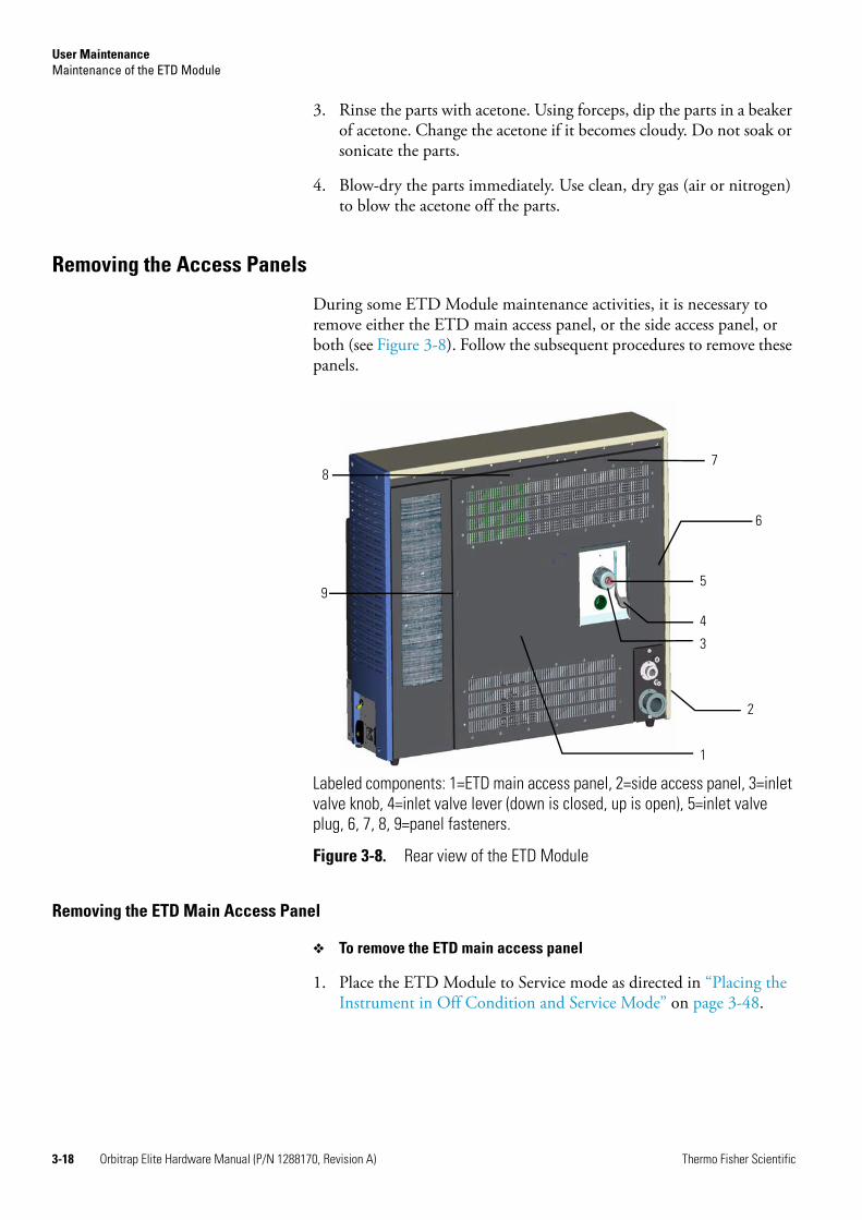
User MaintenanceMaintenance of the ETD Module
3-18 Orbitrap Elite Hardware Manual (P/N 1288170, Revision A) Thermo Fisher Scientific
3. Rinse the parts with acetone. Using forceps, dip the parts in a beaker of acetone. Change the acetone if it becomes cloudy. Do not soak or sonicate the parts.
4. Blow-dry the parts immediately. Use clean, dry gas (air or nitrogen) to blow the acetone off the parts.
Removing the Access Panels
During some ETD Module maintenance activities, it is necessary to remove either the ETD main access panel, or the side access panel, or both (see Figure 3-8). Follow the subsequent procedures to remove these panels.
Removing the ETD Main Access Panel
To remove the ETD main access panel
1. Place the ETD Module to Service mode as directed in “Placing the Instrument in Off Condition and Service Mode” on page 3-48.
Labeled components: 1=ETD main access panel, 2=side access panel, 3=inlet valve knob, 4=inlet valve lever (down is closed, up is open), 5=inlet valve plug, 6, 7, 8, 9=panel fasteners.
Figure 3-8. Rear view of the ETD Module
5
4
3
6
1
2
9
87

User MaintenanceMaintenance of the ETD Module
Thermo Fisher Scientific Orbitrap Elite Hardware Manual (P/N 1288170, Revision A) 3-19
Note In Service mode, all power to the Orbitrap Elite ETD MS electronics is turned off. There are no user accessible components that carry a voltage in this mode. However, the vacuum pumps continue to operate.
Note The ETD main access panel is interlocked with the ETD Module power. When the ETD main access panel is removed, all power to the ETD Module will be turned off. However, the mechanical pump and turbo pump will continue operating.
2. Remove the inlet valve lever (item 4 in Figure 3-8 on page 3-18) by pulling it down and away from the ETD Module main access panel. Do not rotate the lever upwards. It must remain in its down (closed) position to avoid catastrophic venting of the system.
Caution Rotating the inlet valve lever upwards (to the open position) without the inlet valve plug (item 5 in Figure 3-8) or the ion volume tool in place will cause a catastrophic venting of the system.
3. Unscrew the inlet valve knob (item 3 in Figure 3-8) and remove the inlet valve plug (item 5 in Figure 3-8), the inlet valve knob, and the internal ferrule.
4. Loosen the four panel fasteners (items 6, 7, 8, and 9 in Figure 3-8).
5. The top panel rests on hooks pointing into the upward direction. Tilt the top panel towards you and lift it up and away from the ETD Module.
Removing the ETD Side Access Panel
To remove the ETD side access panel
1. If it is not already in Service mode, place the ETD Module in Service mode as directed in “Placing the Instrument in Off Condition and Service Mode” on page 3-48.
Note In Service mode, all power to the Orbitrap Elite ETD MS electronics is turned off. There are no user accessible components that carry a voltage in this mode. However, the vacuum pumps continue to operate.
Warning Burn Hazard. The reagent vial heaters can be 108 °C (or set point); the transfer line, the restrictor, and the ion source can be at 160 °C. These components may be too hot to touch. Verify that all of these components are safe to touch before handling them.

User MaintenanceMaintenance of the ETD Module
3-20 Orbitrap Elite Hardware Manual (P/N 1288170, Revision A) Thermo Fisher Scientific
Note The ETD side access panel is interlocked with the ETD Module power. When the ETD side access panel is removed, all power to the ETD Module will be turned off. However, the mechanical pump and turbomolecular pump will continue operating.
2. Using an Allen wrench, loosen the captive screws at the top and remove the screws at the bottom of gray plastic side panel and remove the panel.
3. Using a #2 Phillips screwdriver, loosen the three captive screws on the metal side access panel (item 2 in Figure 3-8 on page 3-18) and remove the panel.
Replace the panels by following the above steps in reverse order and reversing the instructions in each step.
Maintenance of the Reagent Ion Source
The reagent ion source consists of an ion volume, filament, and ion source lenses. Because the ion volume is exposed directly to samples introduced into the reagent ion source, it requires the most frequent cleaning. You can access the ion volume assembly with or without an inlet valve.
To restore system performance, always clean the ion volume first, then the ion source lenses. If cleaning either of these components does not restore system performance, try cleaning the entire reagent ion source.
This section contains these maintenance procedures:
• “Cleaning the Ion Volume With an Inlet Valve” on page 3-21
• “Cleaning the Ion Source Lens Assembly” on page 3-33
• “Cleaning the Ion Source Block” on page 3-40
• “Replacing the Ion Source Filament” on page 3-42
Warning Burn Hazard. The reagent vial heaters can be at 108 °C (or set point); the flow restrictor, the transfer line heaters, and the ion source heater can be at 160 °C. These components may be too hot to touch. Verify that all of these components are safe to touch before handling them.
Warning Burn Hazard. Reagent vial heaters, ion source heater, flow restrictor, and transfer lines are accessible under the ETD side access panel. These are heated components. Verify that they are safe to touch before handling them.
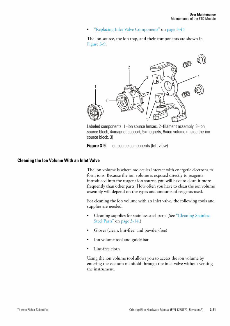
User MaintenanceMaintenance of the ETD Module
Thermo Fisher Scientific Orbitrap Elite Hardware Manual (P/N 1288170, Revision A) 3-21
• “Replacing Inlet Valve Components” on page 3-45
The ion source, the ion trap, and their components are shown in Figure 3-9.
Cleaning the Ion Volume With an Inlet Valve
The ion volume is where molecules interact with energetic electrons to form ions. Because the ion volume is exposed directly to reagents introduced into the reagent ion source, you will have to clean it more frequently than other parts. How often you have to clean the ion volume assembly will depend on the types and amounts of reagents used.
For cleaning the ion volume with an inlet valve, the following tools and supplies are needed:
• Cleaning supplies for stainless steel parts (See “Cleaning Stainless Steel Parts” on page 3-14.)
• Gloves (clean, lint-free, and powder-free)
• Ion volume tool and guide bar
• Lint-free cloth
Using the ion volume tool allows you to access the ion volume by entering the vacuum manifold through the inlet valve without venting the instrument.
Labeled components: 1=ion source lenses, 2=filament assembly, 3=ion source block, 4=magnet support, 5=magnets, 6=ion volume (inside the ion source block, 3)
Figure 3-9. Ion source components (left view)
1
2
3 4
5
6
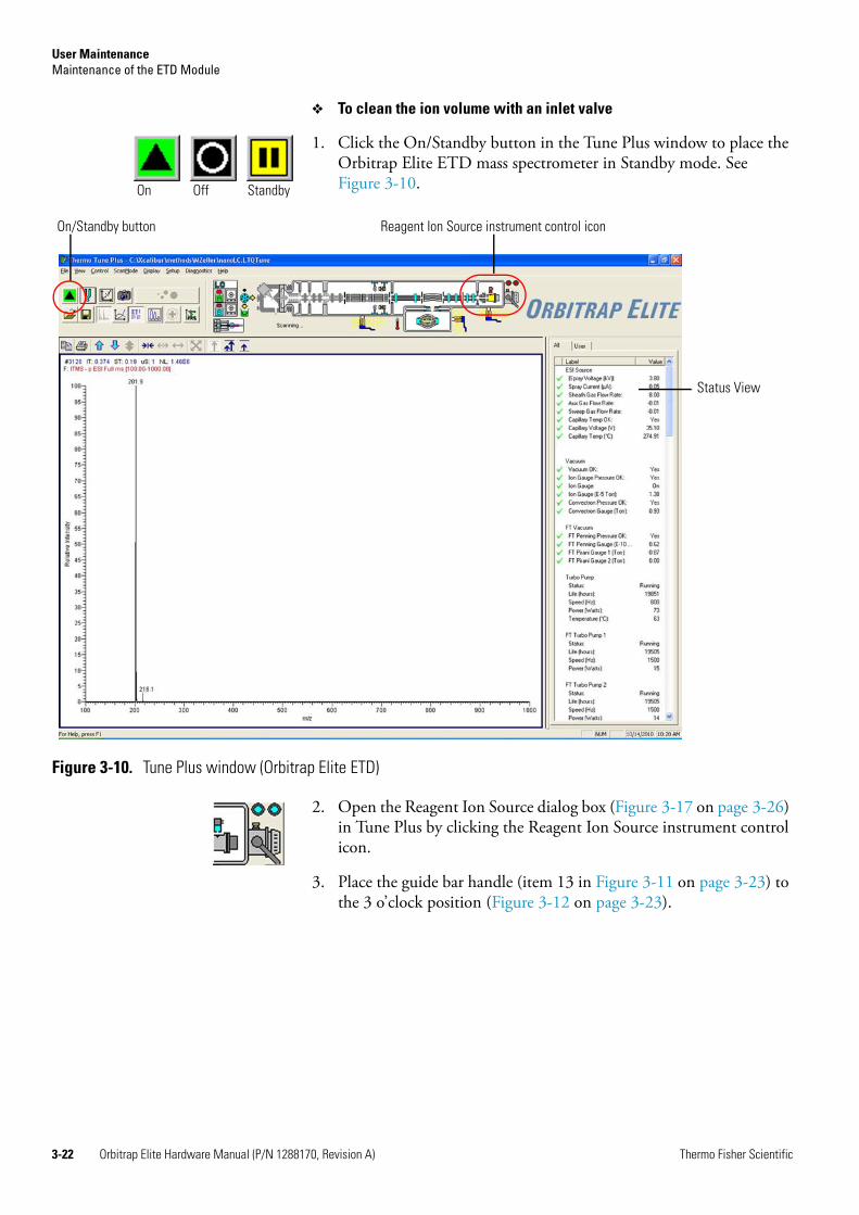
User MaintenanceMaintenance of the ETD Module
3-22 Orbitrap Elite Hardware Manual (P/N 1288170, Revision A) Thermo Fisher Scientific
To clean the ion volume with an inlet valve
1. Click the On/Standby button in the Tune Plus window to place the Orbitrap Elite ETD mass spectrometer in Standby mode. See Figure 3-10.
2. Open the Reagent Ion Source dialog box (Figure 3-17 on page 3-26) in Tune Plus by clicking the Reagent Ion Source instrument control icon.
3. Place the guide bar handle (item 13 in Figure 3-11 on page 3-23) to the 3 o’clock position (Figure 3-12 on page 3-23).
On Off Standby
Figure 3-10. Tune Plus window (Orbitrap Elite ETD)
On/Standby button Reagent Ion Source instrument control icon
Status View
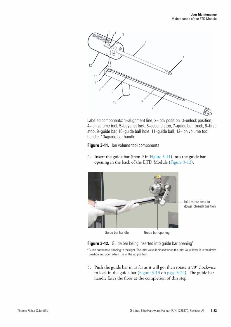
User MaintenanceMaintenance of the ETD Module
Thermo Fisher Scientific Orbitrap Elite Hardware Manual (P/N 1288170, Revision A) 3-23
4. Insert the guide bar (item 9 in Figure 3-11) into the guide bar opening in the back of the ETD Module (Figure 3-12).
5. Push the guide bar in as far as it will go, then rotate it 90° clockwise to lock in the guide bar (Figure 3-13 on page 3-24). The guide bar handle faces the floor at the completion of this step.
Labeled components: 1=alignment line, 2=lock position, 3=unlock position, 4=ion volume tool, 5=bayonet lock, 6=second stop, 7=guide ball track, 8=first stop, 9=guide bar, 10=guide ball hole, 11=guide ball, 12=ion volume tool handle, 13=guide bar handle
Figure 3-11. Ion volume tool components
Figure 3-12. Guide bar being inserted into guide bar openinga
a Guide bar handle is facing to the right. The inlet valve is closed when the inlet valve lever is in the down position and open when it is in the up position.
1 2 3
4
5
67
8
11
12
9
10
13
Inlet valve lever in down (closed) position
Guide bar openingGuide bar handle
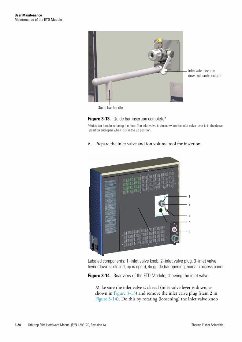
User MaintenanceMaintenance of the ETD Module
3-24 Orbitrap Elite Hardware Manual (P/N 1288170, Revision A) Thermo Fisher Scientific
6. Prepare the inlet valve and ion volume tool for insertion.
Make sure the inlet valve is closed (inlet valve lever is down, as shown in Figure 3-13) and remove the inlet valve plug (item 2 in Figure 3-14). Do this by rotating (loosening) the inlet valve knob
Figure 3-13. Guide bar insertion completea
a Guide bar handle is facing the floor. The inlet valve is closed when the inlet valve lever is in the down position and open when it is in the up position.
Labeled components: 1=inlet valve knob, 2=inlet valve plug, 3=inlet valve lever (down is closed, up is open), 4= guide bar opening, 5=main access panel
Figure 3-14. Rear view of the ETD Module, showing the inlet valve
Inlet valve lever in down (closed) position
Guide bar handle
2
3
1
4
5

User MaintenanceMaintenance of the ETD Module
Thermo Fisher Scientific Orbitrap Elite Hardware Manual (P/N 1288170, Revision A) 3-25
(item 1 in Figure 3-14 on page 3-24) until the inlet valve plug will slide out easily. The inlet valve plug prevents air from entering the vacuum manifold in case the inlet valve is inadvertently opened.
7. Turn the ion volume tool handle to the unlock position, which indicates that the ion volume tool is in position to accept the ion volume. See Figure 3-15.
8. Insert the ion volume tool and evacuate the inlet valve:
a. Insert the guide ball into the guide ball hole.
Figure 3-15. Ion volume tool handle in the unlock position
Labeled components: 1=ion volume tool entry housing, 2=inlet valve opening, 3=first stop, 4=guide bar, 5=ion volume tool, 6=inlet valve lever, 7=inlet valve knob
Figure 3-16. Ion volume tool guide bar first stop
1
2
3
4
5 6
7
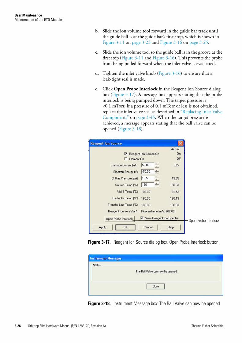
User MaintenanceMaintenance of the ETD Module
3-26 Orbitrap Elite Hardware Manual (P/N 1288170, Revision A) Thermo Fisher Scientific
b. Slide the ion volume tool forward in the guide bar track until the guide ball is at the guide bar’s first stop, which is shown in Figure 3-11 on page 3-23 and Figure 3-16 on page 3-25.
c. Slide the ion volume tool so the guide ball is in the groove at the first stop (Figure 3-11 and Figure 3-16). This prevents the probe from being pulled forward when the inlet valve is evacuated.
d. Tighten the inlet valve knob (Figure 3-16) to ensure that a leak-tight seal is made.
e. Click Open Probe Interlock in the Reagent Ion Source dialog box (Figure 3-17). A message box appears stating that the probe interlock is being pumped down. The target pressure is <0.1 mTorr. If a pressure of 0.1 mTorr or less is not obtained, replace the inlet valve seal as described in “Replacing Inlet Valve Components” on page 3-45. When the target pressure is achieved, a message appears stating that the ball valve can be opened (Figure 3-18).
Figure 3-17. Reagent Ion Source dialog box, Open Probe Interlock button.
Figure 3-18. Instrument Message box: The Ball Valve can now be opened
Open Probe Interlock
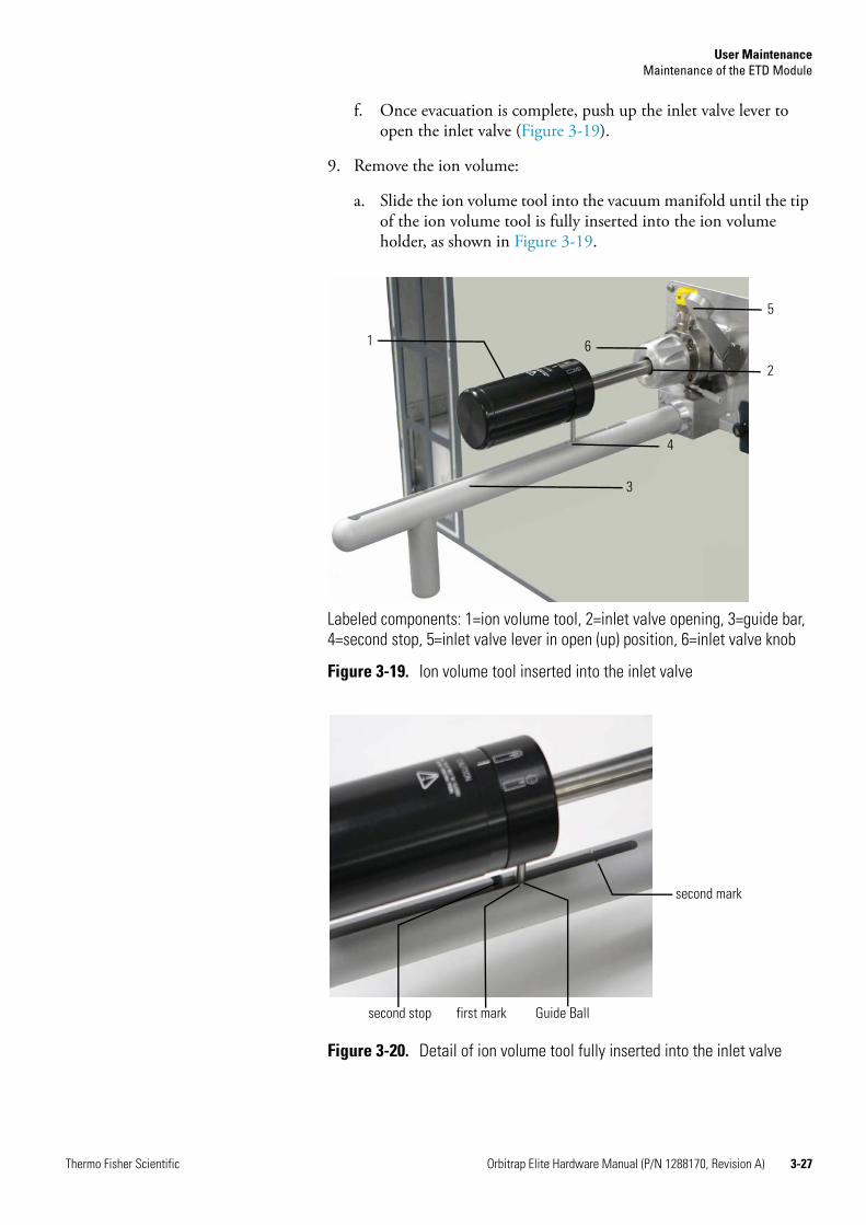
User MaintenanceMaintenance of the ETD Module
Thermo Fisher Scientific Orbitrap Elite Hardware Manual (P/N 1288170, Revision A) 3-27
f. Once evacuation is complete, push up the inlet valve lever to open the inlet valve (Figure 3-19).
9. Remove the ion volume:
a. Slide the ion volume tool into the vacuum manifold until the tip of the ion volume tool is fully inserted into the ion volume holder, as shown in Figure 3-19.
Labeled components: 1=ion volume tool, 2=inlet valve opening, 3=guide bar, 4=second stop, 5=inlet valve lever in open (up) position, 6=inlet valve knob
Figure 3-19. Ion volume tool inserted into the inlet valve
Figure 3-20. Detail of ion volume tool fully inserted into the inlet valve
3
4
2
5
61
second mark
Guide Ballfirst marksecond stop
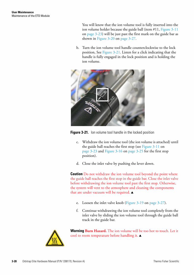
User MaintenanceMaintenance of the ETD Module
3-28 Orbitrap Elite Hardware Manual (P/N 1288170, Revision A) Thermo Fisher Scientific
You will know that the ion volume tool is fully inserted into the ion volume holder because the guide ball (item #11, Figure 3-11 on page 3-23) will be just past the first mark on the guide bar as shown in Figure 3-20 on page 3-27.
b. Turn the ion volume tool handle counterclockwise to the lock position, See Figure 3-21. Listen for a click indicating that the handle is fully engaged in the lock position and is holding the ion volume.
c. Withdraw the ion volume tool (the ion volume is attached) until the guide ball reaches the first stop (see Figure 3-11 on page 3-23 and Figure 3-16 on page 3-25 for the first stop position).
d. Close the inlet valve by pushing the lever down.
Caution Do not withdraw the ion volume tool beyond the point where the guide ball reaches the first stop in the guide bar. Close the inlet valve before withdrawing the ion volume tool past the first stop. Otherwise, the system will vent to the atmosphere and cleaning the components that are under vacuum will be required.
e. Loosen the inlet valve knob (Figure 3-19 on page 3-27).
f. Continue withdrawing the ion volume tool completely from the inlet valve by sliding the ion volume tool through the guide ball track in the guide bar.
Figure 3-21. Ion volume tool handle in the locked position
Warning Burn Hazard. The ion volume will be too hot to touch. Let it cool to room temperature before handling it.

User MaintenanceMaintenance of the ETD Module
Thermo Fisher Scientific Orbitrap Elite Hardware Manual (P/N 1288170, Revision A) 3-29
10. Clean the ion volume:
a. Turn the ion volume tool handle to the unlock position (Figure 3-15 on page 3-25). The ion volume tool handle unlock position icon is shown at the left.
b. Remove the ion volume from the ion volume tool. Using clean gloves, press the ion volume into the tip of the ion volume tool and rotate it to disconnect the bayonet pins from the pin guides. Pull the ion volume out of the ion volume tool, as illustrated in Figure 3-22.
c. Press the ion volume into the ion volume holder and rotate the ion volume to remove it from the ion volume holder See Figure 3-23.
d. Clean ion volume and ion volume holder according to the instructions in “Cleaning Stainless Steel Parts” on page 3-14.
To reinsert the ion volume
1. Press the ion volume into the ion volume holder and rotate the ion volume to secure it to the ion volume holder.
Figure 3-22. Ion volume assembly
Figure 3-23. Separating ion volume and ion volume holder
Bayonet Pin
Ion Volume Spring WasherIon Volume Holder
Ion Volume Tool
Bayonet Pin Guide
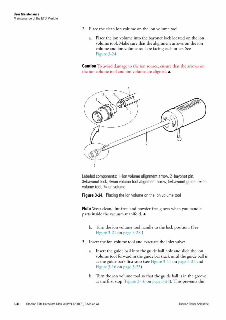
User MaintenanceMaintenance of the ETD Module
3-30 Orbitrap Elite Hardware Manual (P/N 1288170, Revision A) Thermo Fisher Scientific
2. Place the clean ion volume on the ion volume tool:
a. Place the ion volume into the bayonet lock located on the ion volume tool. Make sure that the alignment arrows on the ion volume and ion volume tool are facing each other. See Figure 3-24.
Caution To avoid damage to the ion source, ensure that the arrows on the ion volume tool and ion volume are aligned.
Note Wear clean, lint-free, and powder-free gloves when you handle parts inside the vacuum manifold.
b. Turn the ion volume tool handle to the lock position. (See Figure 3-21 on page 3-28.)
3. Insert the ion volume tool and evacuate the inlet valve:
a. Insert the guide ball into the guide ball hole and slide the ion volume tool forward in the guide bar track until the guide ball is at the guide bar’s first stop (see Figure 3-11 on page 3-23 and Figure 3-16 on page 3-25).
b. Turn the ion volume tool so that the guide ball is in the groove at the first stop (Figure 3-16 on page 3-25). This prevents the
Labeled components: 1=ion volume alignment arrow, 2=bayonet pin, 3=bayonet lock, 4=ion volume tool alignment arrow, 5=bayonet guide, 6=ion volume tool, 7=ion volume
Figure 3-24. Placing the ion volume on the ion volume tool
12 3
4
5
6
7

User MaintenanceMaintenance of the ETD Module
Thermo Fisher Scientific Orbitrap Elite Hardware Manual (P/N 1288170, Revision A) 3-31
probe from being pulled forward when the inlet valve is evacuated.
c. Tighten the inlet valve knob to ensure a leak-tight seal (Figure 3-19 on page 3-27).
d. Click Open Probe Interlock in the Reagent Ion Source dialog box (Figure 3-17 on page 3-26). A message box will appear stating that the probe interlock is being pumped down. The target pressure is <0.1 mTorr. If a pressure of 0.1 mTorr or less is not obtained, the inlet valve seal must be replaced as described in “Replacing Inlet Valve Components” on page 3-45. When the target pressure is achieved, a message will appear stating that the ball valve can be opened. See Figure 3-18 on page 3-26.
e. Once evacuation is complete, push the inlet valve lever up to open the inlet valve. See Figure 3-19 on page 3-27.
4. Reinsert the ion volume:
a. Slide the ion volume tool into the vacuum manifold, as illustrated in Figure 3-19.
b. Listen for a click indicating that the ion volume has connected with the ion source block. The guide ball will be slightly beyond the second stop on the guide bar. See Figure 3-20 on page 3-27.
c. Turn the ion volume tool handle to the unlock position. See Figure 3-25.
i. Withdraw the ion volume tool away from the ion volume about 2.5 cm (1 in) and turn the ion volume tool handle to the lock position. See Figure 3-26 on page 3-32.
ii. Slide the ion volume tool back into the vacuum manifold until the end of the ion volume tool just touches the ion volume.
Figure 3-25. Ion volume tool handle in the unlock position

User MaintenanceMaintenance of the ETD Module
3-32 Orbitrap Elite Hardware Manual (P/N 1288170, Revision A) Thermo Fisher Scientific
iii. If the ion volume tool does not go into the inlet valve completely, the ion volume is not seated properly.
d. Withdraw the ion volume tool until the guide ball reaches the first stop (see Figure 3-11 on page 3-23 and Figure 3-16 on page 3-25).
e. Close the inlet valve by pushing down on the inlet valve lever (Figure 3-14 on page 3-24).
Caution Do not withdraw the ion volume tool beyond the point where the guide ball reaches the first stop in the guide bar. Close the inlet valve before withdrawing the ion volume tool past the first stop. Otherwise, the system vents to the atmosphere.
f. Loosen the inlet valve knob (item 6 in Figure 3-19 on page 3-27).
g. Continue withdrawing the ion volume tool completely from the inlet valve by sliding the ion volume tool through the guide ball track in the guide bar.
5. Remove the ion volume tool and guide bar from the vacuum manifold:
a. Remove the guide bar by rotating it 90 degrees counter-clockwise and sliding it out of the entry housing.
b. Replace the inlet valve plug and tighten the inlet valve knob (item 6 in Figure 3-19 on page 3-27).
c. Click Close in the message stating that the ball valve can be opened. (See Figure 3-18 on page 3-26.)
6. Re-tune the MS detector.
Figure 3-26. Ion volume tool handle in the locked position
User MaintenanceMaintenance of the ETD Module
Thermo Fisher Scientific Orbitrap Elite Hardware Manual (P/N 1288170, Revision A) 3-33
Note Tune Plus provides an evaluation procedure for CI gas pressure under Diagnostics > Diagnostics > Tools > System evaluation > Reagent CI gas pressure evaluation. Thermo Fisher Scientific recommends performing this procedure after replacing the filament and/or the ion volume.
Cleaning the Ion Source Lens Assembly
If cleaning the ion volume did not restore system performance, try cleaning the ion source lens assembly. The ion source lens assembly comes in direct contact with reagent ions introduced into the ETD Module and needs to be cleaned periodically (though not as often as the ion volume).
To clean the ion source lens assembly
1. Prepare the ETD Module for maintenance:
a. Prepare a clean work area by covering the area with a clean lint-free cloth.
b. Shut down and vent the ETD Module. (See “Shutting Down the Instrument” on page 2-7.)
Caution Shut down and unplug the Orbitrap Elite ETD mass spectrometer before proceeding with the next steps of this procedure.
Note Wear clean, lint- and powder-free gloves when you handle parts inside the vacuum manifold.
2. Remove the ion source assembly:
a. Remove the main access panel of the ETD Module (item 1 in Figure 3-8 on page 3-18). Follow the procedures in “Removing the ETD Main Access Panel” on page 3-18.
Warning Burn Hazard. The ion source may be too hot to touch even if the cooling nitrogen has completed its cycle. Be sure that the ion source has cooled to room temperature before handling it.

User MaintenanceMaintenance of the ETD Module
3-34 Orbitrap Elite Hardware Manual (P/N 1288170, Revision A) Thermo Fisher Scientific
Caution It is good practice to keep the inlet valve lever in the down (closed) position whenever it is not explicitly required to be in the up position (open), even if the vacuum manifold is at atmospheric pressure. This is to be consistent with maintenance procedures that rely on the inlet valve lever being closed at the appropriate step to prevent the accidental loss of vacuum. If the vacuum is accidently lost the system may be damaged. At a minimum, the components that were under vacuum might have to be cleaned.
b. Remove all connectors between the components on the vacuum manifold probe plate (item #10, Figure 3-27 on page 3-34) and the ETD Control PCB (Figure 1-17 on page 1-22).
c. Remove the valve shield from the vacuum manifold probe plate (Figure 3-28) by loosening the four screws at the corners of the shield.
Labeled components: 1=inlet valve plug, 2=vacuum manifold, 3=inlet valve lever, 4=guide bar, 5=entry housing, 6=inlet valve knob, 7=inlet valve block, 8=foreline hose connection, 9=12 pin feedthrough, 10=vacuum manifold probe plate, 11=ball valve housing, 12= inlet valve solenoid
Figure 3-27. Inlet valve components (ion volume tool not shown)

User MaintenanceMaintenance of the ETD Module
Thermo Fisher Scientific Orbitrap Elite Hardware Manual (P/N 1288170, Revision A) 3-35
d. Remove the foreline hose on the source from its connection (Figure 3-29 and item 8 in Figure 3-27).
e. Remove the four screws holding the vacuum manifold probe plate (Figure 3-30 and item 10 in Figure 3-27 on page 3-34). Support the plate with your hand as shown in Figure 3-30. Arrows point to the four hex screw locations (items 1–4).
Figure 3-28. Valve shield (1) covering the vacuum manifold probe plate
Figure 3-29. Removing the foreline hose from its connection
1

User MaintenanceMaintenance of the ETD Module
3-36 Orbitrap Elite Hardware Manual (P/N 1288170, Revision A) Thermo Fisher Scientific
f. Remove the vacuum manifold probe plate (Figure 3-31 on page 3-36).
g. Unplug the 12-pin feedthrough harness from the feedthrough (Figure 3-32).
Figure 3-30. Unscrewing the vacuum manifold probe plate
Figure 3-31. Removing the vacuum manifold probe plate
1 2
34 (at lower left corner of manifold probe plate)

User MaintenanceMaintenance of the ETD Module
Thermo Fisher Scientific Orbitrap Elite Hardware Manual (P/N 1288170, Revision A) 3-37
h. Remove the ion source assembly from the vacuum manifold (Figure 3-33 on page 3-38) by first loosening the ion source thumbscrews (item 2 in Figure 3-32).
i. Second, as you remove the ion source assembly (item 1 in Figure 3-33) gently shift it to the left (arrow 2 in Figure 3-33) before and while pulling it out. This will allow the ion source assembly to disengage from the transfer line bellows (item 3 in Figure 3-33) as it is removed. Alternatively, gently depress the transfer line bellows (Figure 3-32 on page 3-37) to disengage it from the ion source assembly.
Labeled components: 1=unplugged 12 pin feedthrough, 2=thumbscrews, 3=transfer line bellows, 4=ion source assembly
Figure 3-32. Interior of vacuum manifold
1 2 3
24

User MaintenanceMaintenance of the ETD Module
3-38 Orbitrap Elite Hardware Manual (P/N 1288170, Revision A) Thermo Fisher Scientific
The ion source assembly is held together with a clip (item 8 in Figure 3-34 on page 3-39). However, it is necessary to keep the tips of your gloved fingers on both the front edge of the ceramic lens holder (item 11 in Figure 3-34) and the back of the magnet yoke (item 3 in Figure 3-34) when you handle the ion source assembly. This prevents unsecured components inside of the ceramic lens holder from falling out.
Caution When handling the ion source assembly, it is important to handle it with gentle finger pressure on each end (as instructed above) to keep unsecured components from falling out of the assembly.
Figure 3-33. Removing the ion source assembly from the vacuum manifolda
a The ion source assembly (item 1) is gently shifted to the left (arrow 2) to allow the ion source assembly to disengage from the transfer line bellows (item 3) as it is removed.
2
1 3
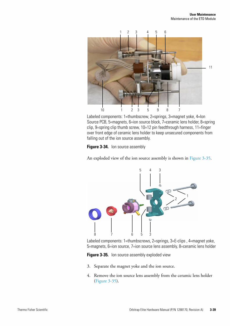
User MaintenanceMaintenance of the ETD Module
Thermo Fisher Scientific Orbitrap Elite Hardware Manual (P/N 1288170, Revision A) 3-39
An exploded view of the ion source assembly is shown in Figure 3-35.
3. Separate the magnet yoke and the ion source.
4. Remove the ion source lens assembly from the ceramic lens holder (Figure 3-35).
Labeled components: 1=thumbscrew, 2=springs, 3=magnet yoke, 4=Ion Source PCB, 5=magnets, 6=ion source block, 7=ceramic lens holder, 8=spring clip, 9=spring clip thumb screw, 10=12 pin feedthrough harness, 11=finger over front edge of ceramic lens holder to keep unsecured components from falling out of the ion source assembly.
Figure 3-34. Ion source assembly
Labeled components: 1=thumbscrews, 2=springs, 3=E-clips , 4=magnet yoke, 5=magnets, 6=ion source, 7=ion source lens assembly, 8=ceramic lens holder
Figure 3-35. Ion source assembly exploded view
1 2 3 4 5 6
11
1 2 3 5 9 8 710
12
345
8 7 6 5 3

User MaintenanceMaintenance of the ETD Module
3-40 Orbitrap Elite Hardware Manual (P/N 1288170, Revision A) Thermo Fisher Scientific
5. Clean the ion source lens assembly according to the procedure in “Cleaning Stainless Steel Parts” on page 3-14. Pay particular attention to the areas inside the tube and around the holes in the lens assembly.
6. Replace the ion source assembly:
a. Insert the lens assembly into the ceramic lens holder.
b. Reassemble the ion source assembly.
c. Reinstall the ion source assembly into the vacuum manifold by following step 2 in reverse order.
7. Restore the ETD Module to operational status. See “Starting Up the System after a Shutdown” on page 2-9.
Cleaning the Ion Source Block
If cleaning the ion volume and ion source lens assembly does not restore system performance, you might need to clean the ion source block. Generally, you need to clean the ion source block no more than once every six months.
Supplies needed for cleaning the ion source:
• Cleaning supplies
• Gloves (clean, lint-free, and powder-free)
• Lint-free cloth
To clean the ion source block
1. Prepare the ETD Module for maintenance:
a. Prepare a clean work area by covering the area with lint-free cloth.
b. Shut down and vent the Orbitrap Elite ETD mass spectrometer. (See “Shutting Down the Orbitrap Elite Mass Spectrometer Completely” on page 2-7.)
Caution Shut down and unplug the Orbitrap Elite ETD mass spectrometer before proceeding with the next steps of this procedure.
c. Remove the ion source assembly by following the procedures in step 2 in “Cleaning the Ion Source Lens Assembly” on page 3-33.
Note Wear clean, lint- and powder-free gloves when you handle parts inside the vacuum manifold.

User MaintenanceMaintenance of the ETD Module
Thermo Fisher Scientific Orbitrap Elite Hardware Manual (P/N 1288170, Revision A) 3-41
2. Disassemble the ion source assembly (Figure 3-34 on page 3-39 and Figure 3-35 on page 3-39), remove and disassemble the ion source (Figure 3-36).
a. Remove the magnet yoke and the ion source block with the ion source lens assembly.
b. Remove the ion source lens assembly.
c. Remove the ion source.
d. Remove the three base studs (item 3 in Figure 3-36). Be careful not to damage the leads on the Ion Source PCB (item 4 in Figure 3-36).
e. Gently remove the Ion Source PCB (item 4 in Figure 3-36) from the ion source by loosening the spring clip thumbscrew (item 11 in Figure 3-36) and the spring clip (item 10 in Figure 3-36) and sliding the three cartridge heaters and the temperature sensor (items 2 and 5 in Figure 3-36) off the ion source and pulling the filament (item 1 in Figure 3-36) straight away from the three filament connectors on the Ion Source PCB. Do not bend or twist the cartridge heaters or temperature sensor.
f. Remove the filament and ceramic spacer (items 15 and 1 in Figure 3-36) from the ion source block (item 6 in Figure 3-36).
Labeled components: 1=ion source filament, 2=cartridge heaters, 3=base studs (3×), 4=Ion Source PCB, 5=temperature sensor, 6=ion source block, 7=ion volume key thumbscrew, 8=ion volume pin, 9=ion volume, 10=spring clip, 11=spring clip thumb screw, 12=heater ring, 13=sample inlet aperture (in side of item 6), 14=ceramic spacer
Figure 3-36. Ion source, exploded view
2
2
3
45
7
8
10
11
12 13
14
1
6
9
User MaintenanceMaintenance of the ETD Module
3-42 Orbitrap Elite Hardware Manual (P/N 1288170, Revision A) Thermo Fisher Scientific
g. Remove the ion volume key thumbscrew (item 7 in Figure 3-36 on page 3-41).
Note It is not necessary to remove the ion volume pin (item 8 in Figure 3-36). If you remove it, you should reinsert it just far enough so the ball will keep an ion volume (item 9 in Figure 3-36) from falling out. If the ball extends too far, the ion volume will be difficult to remove.
3. Clean the ion source parts and replace the ion source assembly:
a. Clean each component of the ion source, as described in “Cleaning Stainless Steel Parts” on page 3-14 and “Cleaning Non-Stainless Steel or Hybrid Parts” on page 3-17.
b. Reassemble the ion source block.
c. Reassemble the ion source assembly.
d. Reinstall the ion source assembly into the vacuum manifold by following step 2 of “Cleaning the Ion Source Lens Assembly” on page 3-33 in reverse order.
4. Restore the ETD Module to operational status. See “Starting Up the System after a Shutdown” on page 2-9.
Replacing the Ion Source Filament
The number of ions produced in the ion source is approximately proportional to the filament emission current. If you notice that ion production is low, this might indicate that the filament has failed and needs to be replaced. If the measured emission current is substantially less than the value that the emission current is set to, or if the measured emission current is decreasing over time, then the filament has failed or is failing and needs to be replaced. The ion source filament assembly is shown in Figure 3-37 on page 3-43.
Supplies needed for replacing the ion source filament:
• Filament Assembly DSQ II (P/N 120320-0030)
• Gloves, clean, lint-free, and powder-free
• Protective eyewear
• Lint-free cloth
• Forceps or dental pick

User MaintenanceMaintenance of the ETD Module
Thermo Fisher Scientific Orbitrap Elite Hardware Manual (P/N 1288170, Revision A) 3-43
To replace the ion source filament
1. Prepare the ETD Module for maintenance.
a. Prepare a clean work area by covering the area with lint-free cloth.
b. Shut down and vent the Orbitrap Elite ETD mass spectrometer. (See “Shutting Down the Orbitrap Elite Mass Spectrometer Completely” on page 2-7.)
Caution Shut down and unplug the Orbitrap Elite ETD mass spectrometer before proceeding with the next steps of this procedure.
c. Remove the ion source assembly by following the procedures in step 2 in “Cleaning the Ion Source Lens Assembly” on page 3-33.
Note Wear clean, lint- and powder-free gloves when you handle parts inside the vacuum manifold.
2. Disassemble the ion source assembly (Figure 3-34 on page 3-39 and Figure 3-35 on page 3-39), remove and disassemble the ion source (Figure 3-36 on page 3-41).
a. Remove the ion source lens assembly (item 1 in Figure 3-37).
b. Remove the three base-studs (item 3 in Figure 3-36, item 4 in Figure 3-37).
c. Remove the filament assembly (items 1 and 15 in Figure 3-36, item 5 in Figure 3-37) and ion source block (item 2 in Figure 3-37) from the three filament connectors and cartridge heaters (item 2 in Figure 3-36) on the Ion Source PCB (item 4
Labeled components: 1=ion source lens assembly, 2=ion source block, 3=Ion Source PCB, 4=base studs (3x), 5=ion source filament
Figure 3-37. Ion source lens assembly and ion source
1
5 3
4
2

User MaintenanceMaintenance of the ETD Module
3-44 Orbitrap Elite Hardware Manual (P/N 1288170, Revision A) Thermo Fisher Scientific
in Figure 3-36) according to the procedure in step e of “Cleaning the Ion Source Block“ on page 3-41 .
Note Now is a good time to clean the ion volume and ion source lenses.
3. Inspect and install a new filament assembly:
a. Turn the filament assembly over and, using a strong light and a magnifying glass, verify that the filament wire is centered in the electron lens hole. If necessary, carefully use forceps (or a dental pick) to adjust the filament wire. Figure 3-38 shows the centered filament wire as seen from the bottom of the filament through the electron lens hole.
Note A bent filament can lead to a low or absent anion signal. If the filament wire is bent, not centered, or otherwise damaged, you must replace the filament assembly.
b. Insert the filament into the ceramic spacer of the ion source block (item 14 in Figure 3-36 on page 3-41).
c. Align the filament leads with the Ion Source PCB connectors and gently press the leads into the connectors. Normally, there is a small gap (about 0.020 in or 0.50 mm) between the filament and the connectors. The gap allows the ceramic filament centering ring (spacer) to properly position and align the electron lens hole with the ion volume.
d. Reinstall the three base-studs (item 3 in Figure 3-36, item 4 in Figure 3-37 on page 3-43).
4. Reassemble ion source and ion source assembly.
5. Insert the ion source assembly into the vacuum manifold.
Figure 3-38. Filament wire as seen from the bottom of the filament through the electron lens hole
Centered wire
Direction of light source

User MaintenanceMaintenance of the ETD Module
Thermo Fisher Scientific Orbitrap Elite Hardware Manual (P/N 1288170, Revision A) 3-45
6. Restore the ETD Module to operational status. See “Starting Up the System after a Shutdown” on page 2-9.
Note Tune Plus provides an evaluation procedure for CI gas pressure under Diagnostics > Diagnostics > Tools > System evaluation > Reagent CI gas pressure evaluation. Thermo Fisher Scientific recommends performing this procedure after replacing the filament and/or the ion volume.
Replacing Inlet Valve Components
This topic provides the procedure for replacing inlet valve components. Perform this procedure when the inlet valve seal or the inlet valve is being replaced.
Tools and supplies needed for replacing inlet valve components:
• Inlet Valve Seal Kit (P/N 119265-0003)
• Lint-free cloth
• Wrench, open-ended, 5/16-in
• Wrench, Allen, 4 mm
To replace inlet valve components
1. Pull down the inlet valve lever to close the inlet valve. See Figure 3-39.
2. Rotate the inlet valve knob counter-clockwise until you can easily remove the inlet valve plug.
Figure 3-39. Inlet valve components
Inlet valve knob
Inlet valve plug
Inlet valve lever in the down (closed) position
Guide bar opening
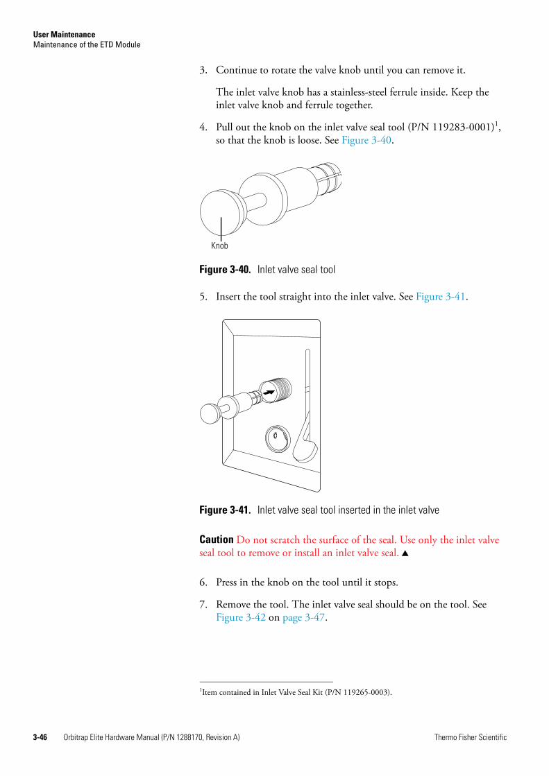
User MaintenanceMaintenance of the ETD Module
3-46 Orbitrap Elite Hardware Manual (P/N 1288170, Revision A) Thermo Fisher Scientific
3. Continue to rotate the valve knob until you can remove it.
The inlet valve knob has a stainless-steel ferrule inside. Keep the inlet valve knob and ferrule together.
4. Pull out the knob on the inlet valve seal tool (P/N 119283-0001)1, so that the knob is loose. See Figure 3-40.
5. Insert the tool straight into the inlet valve. See Figure 3-41.
Caution Do not scratch the surface of the seal. Use only the inlet valve seal tool to remove or install an inlet valve seal.
6. Press in the knob on the tool until it stops.
7. Remove the tool. The inlet valve seal should be on the tool. See Figure 3-42 on page 3-47.
1Item contained in Inlet Valve Seal Kit (P/N 119265-0003).
Figure 3-40. Inlet valve seal tool
Figure 3-41. Inlet valve seal tool inserted in the inlet valve
Knob
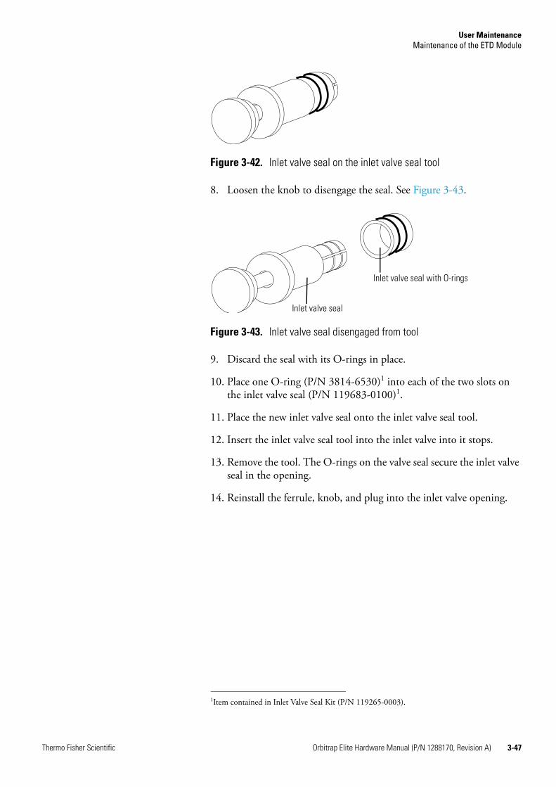
User MaintenanceMaintenance of the ETD Module
Thermo Fisher Scientific Orbitrap Elite Hardware Manual (P/N 1288170, Revision A) 3-47
8. Loosen the knob to disengage the seal. See Figure 3-43.
9. Discard the seal with its O-rings in place.
10. Place one O-ring (P/N 3814-6530)1 into each of the two slots on the inlet valve seal (P/N 119683-0100)1.
11. Place the new inlet valve seal onto the inlet valve seal tool.
12. Insert the inlet valve seal tool into the inlet valve into it stops.
13. Remove the tool. The O-rings on the valve seal secure the inlet valve seal in the opening.
14. Reinstall the ferrule, knob, and plug into the inlet valve opening.
Figure 3-42. Inlet valve seal on the inlet valve seal tool
Figure 3-43. Inlet valve seal disengaged from tool
1Item contained in Inlet Valve Seal Kit (P/N 119265-0003).
Inlet valve seal with O-rings
Inlet valve seal
User MaintenanceMaintenance of the ETD Module
3-48 Orbitrap Elite Hardware Manual (P/N 1288170, Revision A) Thermo Fisher Scientific
Replacing the Reagent Vials
A significant drop of the m/z 202 signal within one hour with the mission current at the correct level indicates a low reagent supply. In this case, you should replace the fluoranthene vial.
Changing the reagent vials requires that the Orbitrap Elite ETD mass spectrometer be placed in Service mode after the vials have cooled. (Vial cooling is done in Off condition.) See the following sections for procedures to be used to change the reagent vials:
• “Placing the Instrument in Off Condition and Service Mode” on page 3-48
• “Installing/Exchanging the Reagent Vials” on page 3-51
The ETD reagent vials are designed to keep the ETD reagent out the lab environment. Removal and replacement of the ETD reagent vials when they are not empty causes excessive puncturing of the septums and reduces their integrity. This could result in ETD reagent (fluoranthene) entering the lab environment. Prevent this from occurring by removing and replacing the ETD reagent vials only when they are empty.
Caution To preserve the integrity of the ETD reagent vial septums, remove and replace the ETD reagent vials only when they are empty. Do not reinstall used vials.
Note Store and handle all chemicals in accordance with standard safety procedures. The Material Safety Data Sheet (MSDS) describing the chemicals being used should be freely available to lab personnel for them to examine at any time. Material Safety Data Sheets (MSDSs) provide summarized information on the hazard and toxicity of specific chemical compounds.MSDSs also provide information on the proper handling of compounds, first aid for accidental exposure, and procedures for cleaning spills or dealing with leaks. Producers and suppliers of chemical compounds are required by law to provide their customers with the most current health and safety information in the form of an MSDS. Read the MSDS for each chemical you use. Dispose of all laboratory reagents in the appropriate manner (see the MSDS).
Safety information about fluoranthene is given in Appendix A: “Fluoranthene”.
Placing the Instrument in Off Condition and Service Mode
The power switches control power to the Orbitrap Elite ETD mass spectrometer (MS and ETD Module). The ETD Module power switches control the power to the ETD Module only. When the

User MaintenanceMaintenance of the ETD Module
Thermo Fisher Scientific Orbitrap Elite Hardware Manual (P/N 1288170, Revision A) 3-49
Orbitrap Elite ETD MS is fully operational (all systems On), the MS Main Power switch is in the On position and the FT Electronics switch is in the operating (On) position.
Normally, the ETD Module Power and Service switches remain On. Use the FT Electronics switch on the MS unit to place the Orbitrap Elite ETD mass spectrometer in Service mode. Turn On and Off the instrument (both ETD Module and MS) with the MS Main Power switch.
Note The instructions that follow assume that no analyte is flowing into the API source.
To place the Orbitrap Elite ETD mass spectrometer in Off Condition and Service mode and to verify that the vials are safe to handle
1. If the Tune Plus window is not already open, choose Start > Programs > Thermo Instruments > LTQ > LTQ Tune from the taskbar. The Tune Plus window appears. (See Figure 3-10 on page 3-22.)
You can determine the state of the MS detector by observing the state of the On/Standby button on the Control/Scan Mode toolbar. The three different states of the On/Standby button are shown at the left.
2. Choose Control > Off from the Tune Plus pull-down menu to place the system in Off condition. When the mass spectrometer is in Off condition, the Orbitrap Elite ETD MS turns off the ion source sheath gas, auxiliary gas, high voltage, and all of the ETD Module heaters.
Note It is important to choose Control > Off from the Tune Plus pull-down menu in order to shut down all of the ETD Module heaters.
3. Click the reagent ion source portion of the instrument control icon at the top of the Tune Plus window. The Reagent Ion Source dialog box appears (Figure 3-44).
Warning Burn Hazard. When mass spectrometer and ETD Module system are turned On, the flow restrictor, the transfer line heaters, and the ion source heater can be at 160 °C. The vial heaters can be at 108 °C (or set point). Do not attempt to replace reagent vials or to service heated components until you have determined that they have cooled to a safe temperature for handling.
On Off Standby

User MaintenanceMaintenance of the ETD Module
3-50 Orbitrap Elite Hardware Manual (P/N 1288170, Revision A) Thermo Fisher Scientific
Observe the temperature of Vial 1 in the Actual column of the Reagent Ion Source dialog box (Figure 3-44). Nitrogen cooling gas will flow until the vial reaches 70 °C. (See “Turning Off the Reagent Ion Source: What to Expect” on page 2-14.) Allow up to 90 minutes for the vial temperature to reach ambient temperature (about 30 °C).
4. Toggle the FT Electronics switch to Service mode (Off ) when the vial has reached a temperature that is safe for handling (about 30 °C). Toggling the FT Electronics switch to Service mode turns off all components except the turbomolecular pumps and the forepumps in both the mass spectrometer and the ETD Module.
Figure 3-44. Reagent Ion Source dialog box
actual vial temperature in °C
Warning Burn Hazard. Do not attempt to handle the vials or vial holders when the cooling nitrogen stops. They are still too hot to handle when the cooling nitrogen stops at a vial temperature of 70 °C.Allow the vials to cool to about 30 °C (allow up to 90 minutes after the cooling gas stops) before proceeding with the next step and handling the vials.

User MaintenanceMaintenance of the ETD Module
Thermo Fisher Scientific Orbitrap Elite Hardware Manual (P/N 1288170, Revision A) 3-51
Note Do not place the ETD Module Service switch into its Service mode (Off ) position while the MS switches are left in their On positions. This could cause communication problems between the MS and the ETD Module. The ability to control the Service mode for both the MS and the ETD Module at one point (at the FT Electronics switch) is a safety feature.
The Orbitrap Elite ETD mass spectrometer is now in Service mode and the vials are at a safe temperature for handling.
Installing/Exchanging the Reagent Vials
After the reagent vial heaters have cooled to room temperature, the reagent vials are ready to be installed or exchanged.
To install or exchange the reagent vials
1. Remove the back panel from the ETD Module. (See “Removing the ETD Main Access Panel” on page 3-18.) This exposes the reagent inlet source heating unit, which has its own cover (Figure 3-45 on page 3-52).
2. Make sure that the vial heater cover is cool to the touch.
Warning Burn Hazard. Do not place the system in Service mode until the vials reach a safe temperature (about 30 °C). System temperature monitoring will stop when the system is placed in Service mode. Do not attempt to handle the vials, the vial holders, or the heater assembly until a safe temperature is reached (about 30 °C).
Warning Burn Hazard. Follow the procedures described in “Placing the Instrument in Off Condition and Service Mode” on page 3-48 before removing the back panel of the ETD Module. Removing the back panel before the system is placed in Service mode will open the panel electrical interlocks and stop all system activity including temperature monitoring. In the absence of temperature monitoring, you might attempt to handle the vials before it is safe to do so.
Warning Burn Hazard. The vial heaters can be at 108 °C (or set point). Allow sufficient time for the vials to cool (up to 90 minutes) and then place the system in Service mode. (See “Placing the Instrument in Off Condition and Service Mode” on page 3-48.) Verify that the vial heater cover is safe to handle before attempting to remove the vial holders and reagent vials.

User MaintenanceMaintenance of the ETD Module
3-52 Orbitrap Elite Hardware Manual (P/N 1288170, Revision A) Thermo Fisher Scientific
3. Put on a pair of new, white nitrile clean room gloves and protective eye wear.
4. Using a Phillips screwdriver, remove the screws in the vial heater cover. The vial heater cover is located on the right side of the ETD Module as you view it from the back of the Orbitrap Elite ETD mass spectrometer (Figure 3-45).
5. Remove the vial holder by gently pulling it out of the vial heater.
6. Remove the empty vial if it is present. The vial holder is a cylindrical tube with a handling knob at one end and ribs along its length. See Figure 3-46. These ribs prevent the vial holder from rotating once it is placed into the vial heater. Figure 3-47 on page 3-53 shows the tab and ribs of a vial holder in the vial heater.
Note Dispose of an empty fluoranthene vial in accordance with its MSDS.
Figure 3-45. ETD Module with back panel removed
Reagent Inlet Source Unit
Vial Heater Cover
Warning Avoid exposure to potentially harmful materials.Always wear protective gloves and safety glasses when you handle solvents or corrosives. Also contain waste streams and use proper ventilation. Refer to your supplier's Material Safety Data Sheet (MSDS) for proper handling of a particular compound.
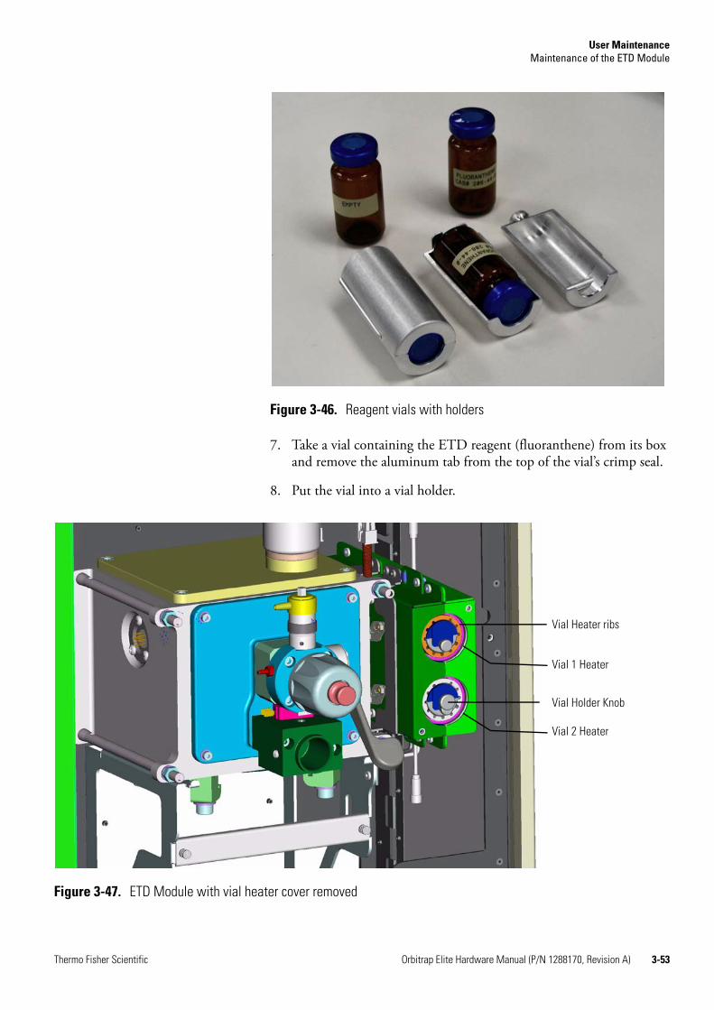
User MaintenanceMaintenance of the ETD Module
Thermo Fisher Scientific Orbitrap Elite Hardware Manual (P/N 1288170, Revision A) 3-53
7. Take a vial containing the ETD reagent (fluoranthene) from its box and remove the aluminum tab from the top of the vial’s crimp seal.
8. Put the vial into a vial holder.
Figure 3-46. Reagent vials with holders
Figure 3-47. ETD Module with vial heater cover removed
Vial Heater ribs
Vial 1 Heater
Vial Holder Knob
Vial 2 Heater

User MaintenanceMaintenance of the ETD Module
3-54 Orbitrap Elite Hardware Manual (P/N 1288170, Revision A) Thermo Fisher Scientific
9. Place this ETD reagent vial and its vial holder into the Vial 1 heater (top vial heater). Gently slide the vial holder into the vial heater.
10. Place the empty vial from the box into the other vial holder if an empty vial is not already installed.
11. Place this empty vial and its vial holder into the Vial 2 heater (bottom vial heater) if an empty vial is not already installed.
Caution If no vial is placed in the Vial 2 heater, the ETD Module will not operate correctly and the filament will burn out.
12. Reinstall the vial heater cover over the vial heaters.
13. Reinstall the back panel of the ETD Module. See “Removing the ETD Main Access Panel” on page 3-18. The ETD Module will not turn on unless the back panel is installed.
14. Start the system:
a. Toggle the FT Electronics switch to the On position.The system will boot to Standby mode. Then ion source heater, flow restrictor, and transfer line heaters will start heating. Monitor these temperatures in the Status View on the right side of the Tune Plus window. (See Figure 3-10 on page 3-22.) They will have green check marks when they have reached their operating temperatures.
b. Select the Reagent Ion Source On check box in the Reagent Ion Source dialog box when the ion source heater, flow restrictor, and transfer line heaters are at their operating temperatures. (See Figure 3-44 on page 3-50.)
The Orbitrap Elite ETD mass spectrometer is now ready for use.
Changing the Reagent Ion Source Flow Restrictors
To change the reagent ion source flow restrictors
1. Shut down completely the instrument according to the procedures in “Shutting Down the Orbitrap Elite Mass Spectrometer Completely” on page 2-7.
Warning Health Hazard. The empty vial in the Vial 2 heater is an integral part of the carrier/CI gas system. It is necessary to keep the carrier/CI gas system closed to the laboratory. If no vial is placed in the Vial 2 heater, the carrier/CI gas containing the reagent might escape to the laboratory causing a safety problem.
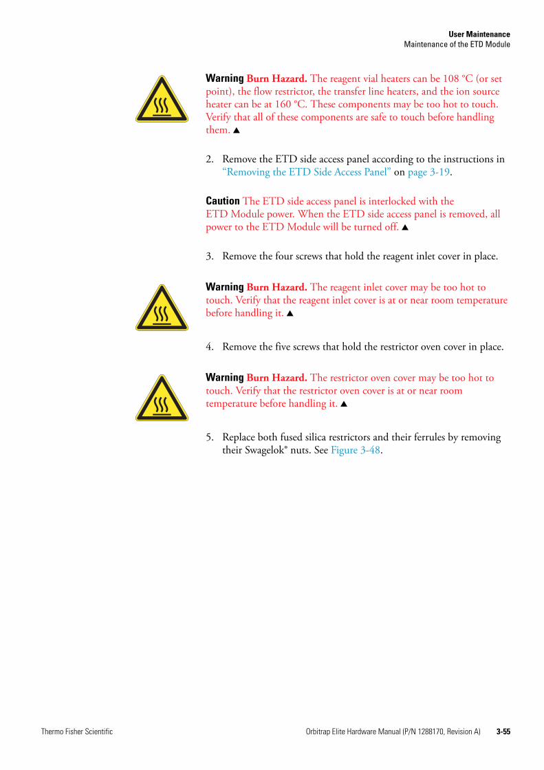
User MaintenanceMaintenance of the ETD Module
Thermo Fisher Scientific Orbitrap Elite Hardware Manual (P/N 1288170, Revision A) 3-55
2. Remove the ETD side access panel according to the instructions in “Removing the ETD Side Access Panel” on page 3-19.
Caution The ETD side access panel is interlocked with the ETD Module power. When the ETD side access panel is removed, all power to the ETD Module will be turned off.
3. Remove the four screws that hold the reagent inlet cover in place.
4. Remove the five screws that hold the restrictor oven cover in place.
5. Replace both fused silica restrictors and their ferrules by removing their Swagelok® nuts. See Figure 3-48.
Warning Burn Hazard. The reagent vial heaters can be 108 °C (or set point), the flow restrictor, the transfer line heaters, and the ion source heater can be at 160 °C. These components may be too hot to touch. Verify that all of these components are safe to touch before handling them.
Warning Burn Hazard. The reagent inlet cover may be too hot to touch. Verify that the reagent inlet cover is at or near room temperature before handling it.
Warning Burn Hazard. The restrictor oven cover may be too hot to touch. Verify that the restrictor oven cover is at or near room temperature before handling it.
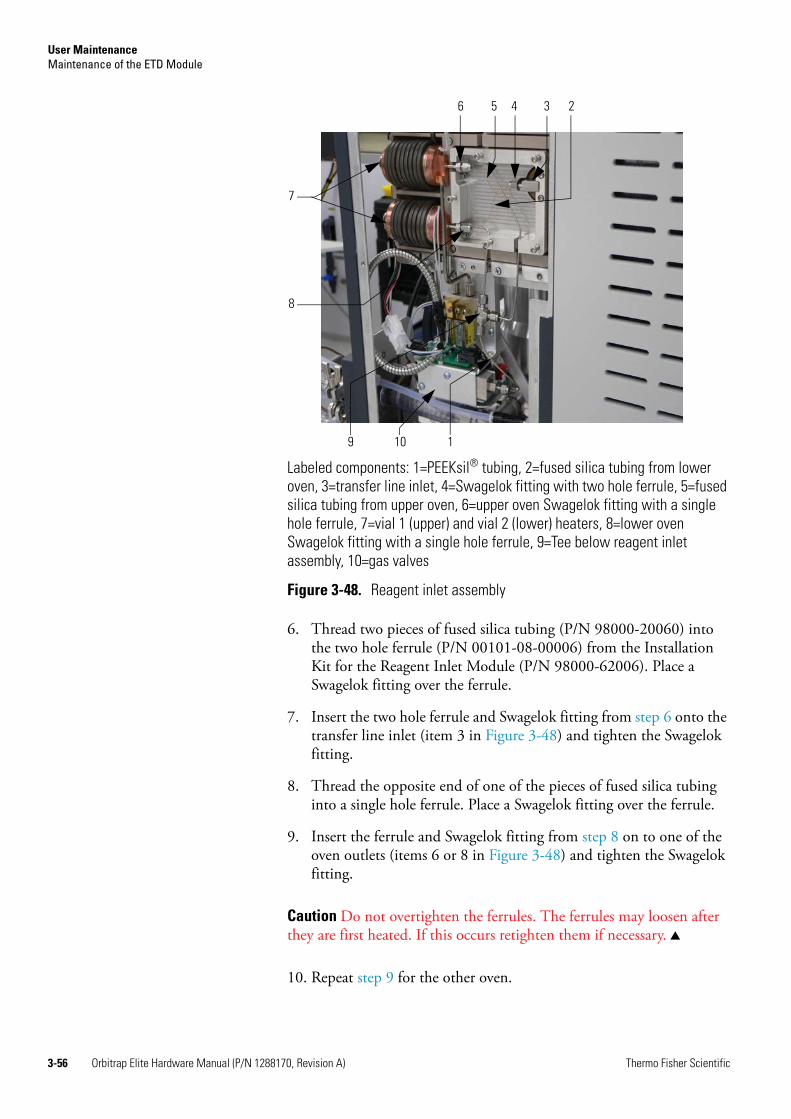
User MaintenanceMaintenance of the ETD Module
3-56 Orbitrap Elite Hardware Manual (P/N 1288170, Revision A) Thermo Fisher Scientific
6. Thread two pieces of fused silica tubing (P/N 98000-20060) into the two hole ferrule (P/N 00101-08-00006) from the Installation Kit for the Reagent Inlet Module (P/N 98000-62006). Place a Swagelok fitting over the ferrule.
7. Insert the two hole ferrule and Swagelok fitting from step 6 onto the transfer line inlet (item 3 in Figure 3-48) and tighten the Swagelok fitting.
8. Thread the opposite end of one of the pieces of fused silica tubing into a single hole ferrule. Place a Swagelok fitting over the ferrule.
9. Insert the ferrule and Swagelok fitting from step 8 on to one of the oven outlets (items 6 or 8 in Figure 3-48) and tighten the Swagelok fitting.
Caution Do not overtighten the ferrules. The ferrules may loosen after they are first heated. If this occurs retighten them if necessary.
10. Repeat step 9 for the other oven.
Labeled components: 1=PEEKsil® tubing, 2=fused silica tubing from lower oven, 3=transfer line inlet, 4=Swagelok fitting with two hole ferrule, 5=fused silica tubing from upper oven, 6=upper oven Swagelok fitting with a single hole ferrule, 7=vial 1 (upper) and vial 2 (lower) heaters, 8=lower oven Swagelok fitting with a single hole ferrule, 9=Tee below reagent inlet assembly, 10=gas valves
Figure 3-48. Reagent inlet assembly
6 5 4 3 2
7
8
9 10 1

User MaintenanceMaintenance of the ETD Module
Thermo Fisher Scientific Orbitrap Elite Hardware Manual (P/N 1288170, Revision A) 3-57
11. Replace the restrictor oven cover and reagent inlet cover removed in step 3 and step 4.
12. Loosen the Swagelok fitting connecting the PEEKsil® tubing (item 1 in Figure 3-48) to the Tee below the reagent inlet assembly (item 9 in Figure 3-48) and from the gas valves (item 10 in Figure 3-48).
13. Replace the old PEEKsil tubing with new PEEKsil tubing (P/N 00109-02-00020) from the Installation Kit for the Reagent Inlet Module (P/N 98000-62006).
14. Close the ETD Module and restart the instrument. Follow the procedures given in “Starting Up the System after a Shutdown” on page 2-9.
Cleaning the Fan Filters of the ETD Module
You need to clean the fan filters every four months. The fan filters are located at the rear of the ETD Module on the left side (as viewed from the back of the ETD Module). See Figure 3-49.
To clean the fan filters of the ETD Module
1. Remove the fan filter from the rear of the ETD Module by pulling it out of the fan filter bracket.
2. Wash the fan filters in a solution of soap and water.
3. Rinse the fan filters with tap water.
4. Squeeze the water from the fan filters and allow them to air dry.
5. Reinstall the fan filter in the fan filter bracket.
Figure 3-49. ETD Module, top panel
Fan filters

User MaintenanceMaintenance of the Cooling Circuit
3-58 Orbitrap Elite Hardware Manual (P/N 1288170, Revision A) Thermo Fisher Scientific
Maintenance of the Cooling CircuitThe recirculating chiller and the water filter require maintenance on a regular basis.
Maintenance for the Recirculating Chiller
For the NESLAB ThermoFlex™ 900 recirculating chiller, the checks described in this section should be carried out on a regular basis.
Note For further information and maintenance instructions, refer to the manufacturer’s manual supplied with the instrument.
Reservoir
Periodically inspect the fluid inside the reservoir. If cleaning is necessary, flush the reservoir with a cleaning fluid compatible with the circulating system and the cooling fluid.
The cooling fluid should be replaced periodically. Replacement frequency depends on the operating environment and amount of usage.
Fluid Bag Filter
The ThermoFlex 900 recirculating chiller installed in the cooling circuit of the instrument is equipped with a fluid bag filter, which needs to be replaced on a regular basis. Replacement bags are available from Thermo Fisher Scientific.
Condenser Filter
To prevent a loss of cooling capacity and a premature failure of the cooling system, clean the condenser filter regularly. If necessary, replace it.
Replacing the Water Filter Cartridge
The filter removes particulate matter in the cooling system that might damage the flow sensor. The filter cartridge should be replaced annually or as necessary. A replacement is available from Thermo Fisher Scientific (P/N 1284050).
Warning Burn Hazard. Before changing the operating fluid, make sure it is at safe handling temperature.

User MaintenanceMaintenance of the Cooling Circuit
Thermo Fisher Scientific Orbitrap Elite Hardware Manual (P/N 1288170, Revision A) 3-59
To replace the water filter cartridge
1. Place the system in Standby condition as described on page 2-4.
2. Turn off the chiller.
3. The filter is installed on the left instrument side, in the cooling lines of the Orbitrap system between the Peltier element and the flow sensor. See Figure 3-50. Quick couplings connect the filter assembly to the hoses of the cooling lines. Press the thumb latch of each quick coupling to release it; valves in the couplings prevent the water from leaking out. Then remove the complete filter assembly.
4. Remove the filter from the assembly by using a 5/16 inch wrench and pressing against the gray ring on the quick coupling, away from the filter. See Figure 3-51.
Figure 3-50. Installed water filter
Thumb latch
Thumb latch

User MaintenanceMaintenance of the Cooling Circuit
3-60 Orbitrap Elite Hardware Manual (P/N 1288170, Revision A) Thermo Fisher Scientific
5. Insert the new filter into the quick couplings. See Figure 3-52.
Caution Pay special attention to the direction of flow. Reversing the flow can damage both the flow sensor and the filter.
6. Connect the filter assembly to the hoses of the cooling lines.
7. Switch on the chiller system. Check for leaks and check the water level in the chiller. Refill as appropriate.
8. Set the instrument to operating condition.
Figure 3-51. Removing the filter cartridge
Gray ring
Figure 3-52. Filter cartridge with Quick couplers

Thermo Fisher Scientific Orbitrap Elite Hardware Manual (P/N 1288170, Revision A) 4-1
Chapter 4 Replaceable Parts
This chapter contains part numbers for replaceable and consumable parts for the mass spectrometer, data system, and kits. To ensure proper results in servicing the Orbitrap Elite system, order only the parts listed or their equivalent.
Note Not all parts are available for purchase separately. Some parts may only be available for purchase as part of a kit or assembly.
For information on how to order parts, see “Contacting Us” in the front section of this guide.

Replaceable PartsIon Sources
4-2 Orbitrap Elite Hardware Manual (P/N 1288170, Revision A) Thermo Fisher Scientific
Ion SourcesESI probe, for Ion Max source. . . . . . . . . . . . . . . . . . . . . . . . OPTON-20011Low flow metal needle for API 2 probes . . . . . . . . . . . . . . . . OPTON-30004Nanospray II Ion Source . . . . . . . . . . . . . . . . . . . . . . . . . . . . OPTON-20050Static Nanospray . . . . . . . . . . . . . . . . . . . . . . . . . . . . . . . . . . OPTON-20051Dynamic Nanospray . . . . . . . . . . . . . . . . . . . . . . . . . . . . . . . OPTON-97017APCI probe . . . . . . . . . . . . . . . . . . . . . . . . . . . . . . . . . . . . . . OPTON-20012APPI probe . . . . . . . . . . . . . . . . . . . . . . . . . . . . . . . . . . . . . . OPTON-20026HESI-II Probe Kit . . . . . . . . . . . . . . . . . . . . . . . . . . . . . . . . . OPTON 20037High-flow needle insert assembly. . . . . . . . . . . . . . . . . . . . . . OPTON-53010Low-flow needle insert assembly . . . . . . . . . . . . . . . . . . . . . . OPTON-53011

Replaceable PartsParts for the Basic System
Thermo Fisher Scientific Orbitrap Elite Hardware Manual (P/N 1288170, Revision A) 4-3
Parts for the Basic System
Orbitrap Analyzer Installation Kit
Tube, 1/8” × 2.1- 1.4301 . . . . . . . . . . . . . . . . . . . . . . . . . . . . . . . . . .0261000Ferrule, stainless steel; R. 1/8” . . . . . . . . . . . . . . . . . . . . . . . . . . . . . .0520950Ferrule, stainless steel; V. 1/8” . . . . . . . . . . . . . . . . . . . . . . . . . . . . . .0522520Cap nut, stainless steel; 1/8“. . . . . . . . . . . . . . . . . . . . . . . . . . . . . . . .0520890Fitting KJH06-00. . . . . . . . . . . . . . . . . . . . . . . . . . . . . . . . . . . . . . . .1221620
Pumping System
For a schematical overview of the pumping system, see Figure 1-23 on page 1-30.
T-piece 13 mm. . . . . . . . . . . . . . . . . . . . . . . . . . . . . . . . . . . . . . . . . .0512360Hose 13 × 3.5; PVC . . . . . . . . . . . . . . . . . . . . . . . . . . . . . . . . . . . . . .0690720Turbomolecular pump HiPace 300. . . . . . . . . . . . . . . . . . . . . . . . . . .1272910Turbomolecular pump; HiPace 80 . . . . . . . . . . . . . . . . . . . . . . . . . . .1272920UHV gauge IKR 270; short . . . . . . . . . . . . . . . . . . . . . . . . . . . . . . . .1181380Compact Pirani Gauge TPR280. . . . . . . . . . . . . . . . . . . . . . . . . . . . .1156400Water cooling for HiPace 300. . . . . . . . . . . . . . . . . . . . . . . . . . . . . . .1272930Water cooling for HiPace 80. . . . . . . . . . . . . . . . . . . . . . . . . . . . . . . .0794742PVC hose, with steel helix; ID=45 mm, L=1.6 m. . . . . . . . . . . . . . . .1184330Hose nipple, DN 40, ISO-KF-45. . . . . . . . . . . . . . . . . . . . . . . . . . . .1159230Venting flange; DN 10, KF-G1/8” . . . . . . . . . . . . . . . . . . . . . . . . . . .1184400Splinter shield for TMPs, with DN 100 CF-F flange . . . . . . . . . . . . .1198590Centering ring, with integrated splinter shield; DN 63 ISO . . . . . . . .1198600Anti-magnetic cover for IKR 270 . . . . . . . . . . . . . . . . . . . . . . . . . . . .1181390Gasket; NW 100 CF, copper . . . . . . . . . . . . . . . . . . . . . . . . . . . . . . .0552440Hose, metal; KF16-KF25 - 250mm . . . . . . . . . . . . . . . . . . . . . . . . . .1154130Gasket; copper, NW 35 . . . . . . . . . . . . . . . . . . . . . . . . . . . . . . . . . . .0550480Metal tube, KF NW16×250. . . . . . . . . . . . . . . . . . . . . . . . . . . . . . . .0524260KF Tee piece; NW 16 KF, stainless steel . . . . . . . . . . . . . . . . . . . . . . .0524230Centering ring with o-ring; DN 16, Viton . . . . . . . . . . . . . . . . . . . . .0522140Centering ring with o-ring; DN 25, Viton . . . . . . . . . . . . . . . . . . . . .0522150Centering ring; NW 16/10, aluminum-Viton . . . . . . . . . . . . . . . . . .0522200Clamping ring; NW 10/16, KF . . . . . . . . . . . . . . . . . . . . . . . . . . . . .0521830Clamping ring; NW 20/25, KF . . . . . . . . . . . . . . . . . . . . . . . . . . . . .0521560Reducing cross piece; DN40/DN16 KF. . . . . . . . . . . . . . . . . . . . . . .1184310Metal tube; DN40x500 . . . . . . . . . . . . . . . . . . . . . . . . . . . . . . . . . . .1184350Metal tube; DN40x750 . . . . . . . . . . . . . . . . . . . . . . . . . . . . . . . . . . .1181290Hose clamp; NW 40 . . . . . . . . . . . . . . . . . . . . . . . . . . . . . . . . . . . . .1181320Centering ring; NW 40 KF, aluminum-Viton . . . . . . . . . . . . . . . . . .0522260Tension ring; NW 32/40 KF . . . . . . . . . . . . . . . . . . . . . . . . . . . . . . .1181250Clamping screw; DN63-100 ISO, aluminum. . . . . . . . . . . . . . . . . . .1042670Flexible metal hose KF NW 16x500. . . . . . . . . . . . . . . . . . . . . . . . . .0534500
Replaceable PartsParts for the Basic System
4-4 Orbitrap Elite Hardware Manual (P/N 1288170, Revision A) Thermo Fisher Scientific
Water Supply
For a schematical overview of the cooling water circuit, see Figure 1-32 on page 1-42.
Quick coupling insert; 9.6 mm . . . . . . . . . . . . . . . . . . . . . . . . . . . . . 1141640Quick coupling body; 9.6 mm. . . . . . . . . . . . . . . . . . . . . . . . . . . . . . 1138960Hose; 9 x 3, black, PVC . . . . . . . . . . . . . . . . . . . . . . . . . . . . . . . . . . 1049540Hose; 6 x 1, Teflon . . . . . . . . . . . . . . . . . . . . . . . . . . . . . . . . . . . . . . 1042660Quick coupling insert; Delrin Acetal, NW 6.4 . . . . . . . . . . . . . . . . . 1185030Quick coupling body; Delrin Acetal, NW 6.4 . . . . . . . . . . . . . . . . . . 1185020Clamping piece 8/16 . . . . . . . . . . . . . . . . . . . . . . . . . . . . . . . . . . . . . 0370130Adaptor hose nipple; male, 1/2 x 10 . . . . . . . . . . . . . . . . . . . . . . . . . 1185840Flow control sensor . . . . . . . . . . . . . . . . . . . . . . . . . . . . . . . . . . . . . . 1191740Filter cartridge; 50 μm DIF . . . . . . . . . . . . . . . . . . . . . . . . . . . . . . . . 1284050
Gas Supply
For a schematical overview of the gas supply, see Figure 1-28 on page 1-37.
Bulkhead union; 1/16”, for hose 4 x 1 (for P/N 069 1130) . . . . . . . . 1153660Bulkhead union; 1/8”×1/8” . . . . . . . . . . . . . . . . . . . . . . . . . . . . . . . . 0523450Hose; 4 x 1, Teflon . . . . . . . . . . . . . . . . . . . . . . . . . . . . . . . . . . . . . . 0690280Hose; 4 x 1, polyurethane, blue . . . . . . . . . . . . . . . . . . . . . . . . . . . . . 0691130Capillary 1/16” ID-SS . . . . . . . . . . . . . . . . . . . . . . . . . . . . . . . . . . . . 0605470Plug-in T-piece; 3 x 6mm . . . . . . . . . . . . . . . . . . . . . . . . . . . . . . . . . 1128140Regulator + manometer f. Orbitrap analyzer . . . . . . . . . . . . . . . . . . . 1257670Capillary; 1/16”x0.13x400mm (red), PEEK . . . . . . . . . . . . . . . . . . . 1253830Coupling; 1/16”, SS-100-6 . . . . . . . . . . . . . . . . . . . . . . . . . . . . . . . . 0524340Ferrule; 1/16” GVF 16-000. . . . . . . . . . . . . . . . . . . . . . . . . . . . . . . . 1121110Reducer Swagelok; 1/8” × 1/16”, stainless steel . . . . . . . . . . . . . . . . . 0662880Ferrule; 1/16” GVF/16 . . . . . . . . . . . . . . . . . . . . . . . . . . . . . . . . . . . 0674800Connector 1/8”, for hose OD 4 mm . . . . . . . . . . . . . . . . . . . . . . . . . 1128680Cap nut; 1/16”, stainless steel . . . . . . . . . . . . . . . . . . . . . . . . . . . . . . 0520880Hose; 2 x 1, PTFE. . . . . . . . . . . . . . . . . . . . . . . . . . . . . . . . . . . . . . . 1091650Sleeve; Ø 6 mm . . . . . . . . . . . . . . . . . . . . . . . . . . . . . . . . . . . . . . . . . 1047320Capillary; PEEKsil, 1/16”, 0.1 × 500 mm . . . . . . . . . . . . . . . . . . . . . 1223420Plug, KQ2P-06 . . . . . . . . . . . . . . . . . . . . . . . . . . . . . . . . . . . . . . . . . 1185620Cap, KQ2C-06 . . . . . . . . . . . . . . . . . . . . . . . . . . . . . . . . . . . . . . . . . 1258220
Replaceable PartsParts Lists for the ETD System
Thermo Fisher Scientific Orbitrap Elite Hardware Manual (P/N 1288170, Revision A) 4-5
Parts Lists for the ETD SystemThis section contains parts lists for the components of the ETD System of the Orbitrap Elite ETD mass spectrometer.
Quadrupole Orbitrap analyzer, complete . . . . . . . . . . . . . . . . . . . . . .1239200Housing HCD/ETD . . . . . . . . . . . . . . . . . . . . . . . . . . . . . . . . . . . . .1231740Separating plate HCD/ETD . . . . . . . . . . . . . . . . . . . . . . . . . . . . . . .1231770Screw M 4 x 8 DIN912 . . . . . . . . . . . . . . . . . . . . . . . . . . . . . . . . . . .1044420O-ring 129 X 4 A Viton. . . . . . . . . . . . . . . . . . . . . . . . . . . . . . . . . . .1240520Lid HCD/ETD . . . . . . . . . . . . . . . . . . . . . . . . . . . . . . . . . . . . . . . . .1231760Screw-in connector; 1/16” . . . . . . . . . . . . . . . . . . . . . . . . . . . . . . . . .1186150Gasket; NW 63 ISO, aluminum/Viton . . . . . . . . . . . . . . . . . . . . . . .0554060Blank flange; stainless steel, NW 63 . . . . . . . . . . . . . . . . . . . . . . . . . .0652620Clamping screw; DN63-100, aluminum . . . . . . . . . . . . . . . . . . . . . .1028380Washer 8.4; stainless steel . . . . . . . . . . . . . . . . . . . . . . . . . . . . . . . . . .0470070Screw, hexagonal; M 8 x 35, stainless steel . . . . . . . . . . . . . . . . . . . . .0454400Washer 8.4 x 11 x 1.5, stainless steel. . . . . . . . . . . . . . . . . . . . . . . . . .0470860Screw M8 x 35; stainless steel . . . . . . . . . . . . . . . . . . . . . . . . . . . . . . .0454250Centering ring NW 16 Viton. . . . . . . . . . . . . . . . . . . . . . . . . . . . . . .0522140Feedthrough; 8-fold 1,5kV DN16KF. . . . . . . . . . . . . . . . . . . . . . . . .1231750O-ring; 118 X 5 A, Viton. . . . . . . . . . . . . . . . . . . . . . . . . . . . . . . . . .1168240Box f. feedthrough; KF16 / Sub-D9 . . . . . . . . . . . . . . . . . . . . . . . . . .1231800Cylindrical Screw ISO4762-M6X12-A4. . . . . . . . . . . . . . . . . . . . . . .0453300
Vacuum system ETD
Flange clamp; KF16 . . . . . . . . . . . . . . . . . . . . . . . . . . . . . . . . . . . . . .1145860PUMP, TURBO, EDWARDS EXT75DX ISO100, TNR . . 00108-01-00016Splinter guard, DN_63_ISO . . . . . . . . . . . . . . . . . . . . . . . . . . . . . . .1198600Metal hose, DN 16 ISO-KF x500 . . . . . . . . . . . . . . . . . . . . . . . . . . .1181410Centering ring with o-ring; DN 16, Viton . . . . . . . . . . . . . . . . . . . . .0522140Clamping ring; NW 10/16, KF . . . . . . . . . . . . . . . . . . . . . . . . . . . . .0521830Hose flange; NW 25 KF. . . . . . . . . . . . . . . . . . . . . . . . . . . . . . . . . . .1042330Centering ring, with o ring; DN 25, Viton . . . . . . . . . . . . . . . . . . . .0522150Clamping ring, DN 25. . . . . . . . . . . . . . . . . . . . . . . . . . . . . . . . . . . .0521560Flange, KF16 - hose OD 19 . . . . . . . . . . . . . . . . . . . . . . . . . . . . . . . .1239340Reducer; DN 16/DN 25, aluminum . . . . . . . . . . . . . . . . . . . . . . . . .0522160PUMP, ROTARY VANE, EDWARDS RV3. . . . . . . . . . . . . . 00108-01-0008KIT, ACCESSORY, MECHANICAL PUMP, RV3 . . . . . . . . . 98000-620007
Gas Supply ETD
Plug-in T-piece; 3 x 6mm. . . . . . . . . . . . . . . . . . . . . . . . . . . . . . . . . .1128140Sleeve 6 mm. . . . . . . . . . . . . . . . . . . . . . . . . . . . . . . . . . . . . . . . . . . .1047320Reducing hose connector, 3.2−>6. . . . . . . . . . . . . . . . . . . . . . . . . . .1239220Hose cutter . . . . . . . . . . . . . . . . . . . . . . . . . . . . . . . . . . . . . . . . . . . .1239280T-piece 13 mm. . . . . . . . . . . . . . . . . . . . . . . . . . . . . . . . . . . . . . . . . .0512360Hose 9 X 3; PVC, black . . . . . . . . . . . . . . . . . . . . . . . . . . . . . . . . . . .1049540Clamping piece 8/16 . . . . . . . . . . . . . . . . . . . . . . . . . . . . . . . . . . . . .0370130

Replaceable PartsParts Lists for the ETD System
4-6 Orbitrap Elite Hardware Manual (P/N 1288170, Revision A) Thermo Fisher Scientific
Hose; 4 X 1, Teflon . . . . . . . . . . . . . . . . . . . . . . . . . . . . . . . . . . . . . . 0690280Clamping ring; stainless steel, NW10/16. . . . . . . . . . . . . . . . . . . . . . 1149200PEEK capillary; 1/16” x 0.040. . . . . . . . . . . . . . . . . . . . . . . . . . . . . . 1245940Ferrule, 1/16”, for GVF/16 . . . . . . . . . . . . . . . . . . . . . . . . . . . . . . . . 0674800Ferrule 1/16” - CTFE, collapsible . . . . . . . . . . . . . . . . . . . . . . . . . . . 1224700
Electronic Parts ETD
Cable Y-ADAPTER/T.PUMP . . . . . . . . . . . . . . . . . . . . . . . . . . . . . . 2108630Coupling; RJ45 BU/2BU . . . . . . . . . . . . . . . . . . . . . . . . . . . . . . . . . 2075210Patch cable; 0.51MT RJ45 gray SFTP. . . . . . . . . . . . . . . . . . . . . . . . 2080870Cable POWER DIS./T-PUMP . . . . . . . . . . . . . . . . . . . . . . . . . . . . 2081200Cable CLT-OFFSET-A . . . . . . . . . . . . . . . . . . . . . . . . . . . . . . . . . . . 2108710Cable IOS ETD/ION OPTIC-S . . . . . . . . . . . . . . . . . . . . . . . . . . . . 2108820UNIT_ION OPTIC SUPPLY ETD . . . . . . . . . . . . . . . . . . . . . . . . . 2108920PCB LTQ CABLE DRIVER . . . . . . . . . . . . . . . . . . . . . . . . . . . . . . 2097780PCB ORBITRAP CABLE RECEIVER. . . . . . . . . . . . . . . . . . . . . . 2097830PCB ETD CABLE RECEIVER . . . . . . . . . . . . . . . . . . . . . . . . . . . . 2097800Cable ETD/LTQ/ORBITRAP-INTERCONNECT 60 . . . . . . . . . . 2108940Cable ETD/LTQ/ORBITRAP-INTERCONNECT 36 . . . . . . . . . . 2108950Cable ETD/LTQ/ORBITRAP-INTERCON SUPPLY . . . . . . . . . . 2108960Coaxial cable; ETD IOS/ANALOG CTRL, J5554 . . . . . . . . . . . . . 2108990Coaxial cable; ETD IOS/ANALOG CTRL, J5555 . . . . . . . . . . . . . 2109000Coaxial cable; ETD IOS/ANALOG CTRL, J5556 . . . . . . . . . . . . . 2109010Cable ANALOG CTRL / ETD IOS . . . . . . . . . . . . . . . . . . . . . . . . 2108970Cable ETD IOS/HCD multipole . . . . . . . . . . . . . . . . . . . . . . . . . . . 2108980Extension cable; 16A C20-C19 2M . . . . . . . . . . . . . . . . . . . . . . . . . 2097050ADAPTER_IOS/MULTIPOLE-HCD . . . . . . . . . . . . . . . . . . . . . . 2100410
Reagent Inlet Module
ASSY, TOOL, ION VOLUME INSERTION/REMOVAL . . . 98000-60028TUBING, PEEKsil, 1/16” OD, 100mm LONG, RoHS. . . .00109-02-00020FRLE, 1HOLE, 1/16 OD, 0.4mm ID, VESP/GRPHT, RO .00101-08-00005FRLE, 2HOLS, 1/16 OD, 0.4mm ID, VESP/GRPHT, RO .00101-08-00006
Inlet Valve Seal Kit . . . . . . . . . . . . . . . . . . . . . . . . . . . . . . . . . . 119265-0003Inlet valve seal removal tool. . . . . . . . . . . . . . . . . . . . . . . . . 119283-0001Spool inlet valve seal . . . . . . . . . . . . . . . . . . . . . . . . . . . . . . 119683-0100O-ring Viton, 0530 ID × 0.082 W . . . . . . . . . . . . . . . . . . . . . 3814-6530
Replaceable PartsParts Lists for the ETD System
Thermo Fisher Scientific Orbitrap Elite Hardware Manual (P/N 1288170, Revision A) 4-7
ETD Reagent Kit
ETD Reagent Kit . . . . . . . . . . . . . . . . . . . . . . . . . . . . . . . . . . .98000-62008Angiotensin I, 1mg . . . . . . . . . . . . . . . . . . . . . . . . . . . . . . . 00301-15517Fluoranthene, 150mg . . . . . . . . . . . . . . . . . . . . . . . . . . . 00301-01-0013
The fluoranthene in your ETD Reagent Kit is Sigma/Aldrich Supelco #48535. The fluoranthene MSDS is obtained from the MSDS link at:
www.sigmaaldrich.com/catalog/search/ProductDetail/SUPELCO/48535
Thermo Fisher Scientific supplies fluoranthene as a two vial kit. One vial contains 150 mg of fluoranthene and the other is the required empty vial.
The angiotensin I in your ETD Reagent Kit is Angiotensin I human acetate hydrate (Sigma/Aldrich #A9650). Angiotensin I is potentially hazardous. Handle it in accordance with its MSDS. The angiotensin I MSDS is obtained from the MSDS link at:
www.sigmaaldrich.com/catalog/search/ProductDetail/SIGMA/A9650

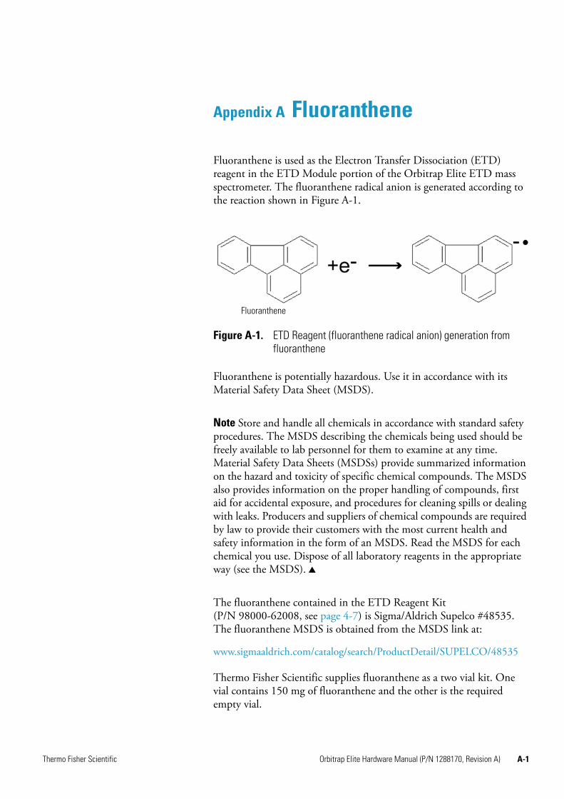
Thermo Fisher Scientific Orbitrap Elite Hardware Manual (P/N 1288170, Revision A) A-1
Appendix A Fluoranthene
Fluoranthene is used as the Electron Transfer Dissociation (ETD) reagent in the ETD Module portion of the Orbitrap Elite ETD mass spectrometer. The fluoranthene radical anion is generated according to the reaction shown in Figure A-1.
Fluoranthene is potentially hazardous. Use it in accordance with its Material Safety Data Sheet (MSDS).
Note Store and handle all chemicals in accordance with standard safety procedures. The MSDS describing the chemicals being used should be freely available to lab personnel for them to examine at any time. Material Safety Data Sheets (MSDSs) provide summarized information on the hazard and toxicity of specific chemical compounds. The MSDS also provides information on the proper handling of compounds, first aid for accidental exposure, and procedures for cleaning spills or dealing with leaks. Producers and suppliers of chemical compounds are required by law to provide their customers with the most current health and safety information in the form of an MSDS. Read the MSDS for each chemical you use. Dispose of all laboratory reagents in the appropriate way (see the MSDS).
The fluoranthene contained in the ETD Reagent Kit (P/N 98000-62008, see page 4-7) is Sigma/Aldrich Supelco #48535. The fluoranthene MSDS is obtained from the MSDS link at:
www.sigmaaldrich.com/catalog/search/ProductDetail/SUPELCO/48535
Thermo Fisher Scientific supplies fluoranthene as a two vial kit. One vial contains 150 mg of fluoranthene and the other is the required empty vial.
Figure A-1. ETD Reagent (fluoranthene radical anion) generation from fluoranthene
Fluoranthene


Thermo Fisher Scientific Orbitrap Elite Hardware Manual (P/N 1288170, Revision A) G-1
Glossary
This section lists and defines terms used in this guide. It also includes acronyms, metric prefixes, symbols, and abbreviations.
A
A ampere
AC alternating current
ADC analog-to-digital converter; a device that converts data from analog to digital form.
adduct ion An ion formed by the joining together of two species, usually an ion and a molecule, and often within the ion source, to form an ion containing all the constituent atoms of both species.
AGC™ See Automatic Gain Control™ (AGC).
APCI See atmospheric pressure chemical ionization (APCI).
APCI corona discharge current The ion current carried by the charged particles in the APCI source. The voltage on the APCI corona discharge needle supplies the potential required to ionize the particles. The APCI corona discharge current is set; the APCI corona discharge voltage varies, as required, to maintain the set discharge current.
See also corona discharge and APCI corona discharge voltage.
APCI corona discharge voltage The high voltage that is applied to the corona discharge needle in the APCI source to produce the APCI corona discharge. The corona discharge voltage varies, as required, to maintain the set APCI spray current.
See also APCI spray current.
APCI manifold The manifold that houses the APCI sample tube and nozzle, and contains the plumbing for the sheath and auxiliary gas.
APCI needle, corona discharge A needle to which a sufficiently high voltage (typically ±3 to ±5 kV) is applied to produce a chemical ionization plasma by the corona discharge mechanism.
See also chemical ionization (CI), chemical ionization (CI) plasma, atmospheric pressure chemical ionization (APCI), and corona discharge.
APCI nozzle The nozzle in the APCI probe that sprays the sample solution into a fine mist.
See also atmospheric pressure chemical ionization (APCI).
APCI sample tube A fused silica tube that delivers sample solution to the APCI nozzle. The APCI sample tube extends from the sample inlet to the APCI nozzle.
See also atmospheric pressure chemical ionization (APCI), and API stack.
APCI source Contains the APCI probe assembly, APCI manifold, and API stack.
See also atmospheric pressure chemical ionization (APCI), APCI manifold, and API stack.
APCI spray current The ion current carried by the charged particles in the APCI source. The APCI corona discharge voltage varies, as required, to maintain the set spray current.
APCI vaporizer A heated tube that vaporizes the sample solution as the solution exits the sample tube and enters the atmospheric pressure region of the APCI source.
See also atmospheric pressure chemical ionization (APCI).
A B C D E F G H I J K L M N O P Q R S T U V W X Y Z

Glossary: API–atmospheric pressure chemical ionization (APCI)
G-2 Orbitrap Elite Hardware Manual (P/N 1288170, Revision A) Thermo Fisher Scientific
API See atmospheric pressure ionization (API).
API atmospheric pressure region The first of two chambers in the API source. Also referred to as the spray chamber.
API capillary-skimmer region The area between the capillary and the skimmer, which is surrounded by the tube lens. It is also the area of first-stage evacuation in the API source.
API heated capillary A tube assembly that assists in desolvating ions that are produced by the ESI or APCI probe.
See also API heated capillary voltage.
API heated capillary voltage The DC voltage applied to the heated capillary. The voltage is positive for positive ions and negative for negative ions.
See also API source and API heated capillary.
API ion transfer capillary A tube assembly that assists in desolvating ions that are produced by the ESI, NSI, or APCI probe.
See also API ion transfer capillary offset voltage and API ion transfer capillary temperature.
API ion transfer capillary offset voltage A DC voltage applied to the ion transfer capillary. The voltage is positive for positive ions and negative for negative ions.
See also API source and API ion transfer capillary.
API ion transfer capillary temperature The temperature of the ion transfer capillary, which should be adjusted for different flow rates.
See also API source and API ion transfer capillary.
API source The sample interface between the LC and the mass spectrometer. It consists of the API probe (ESI or APCI) and API stack.
See also atmospheric pressure ionization (API), ESI source, APCI source, ESI probe, and API stack.
API spray chamber The first of two chambers in the API source. In this chamber the sample liquid exits the probe and is sprayed into a fine mist (ESI or NSI) or is vaporized (APCI) as it is transported to the entrance end of the ion transfer capillary.
API spray shield A stainless steel, cylindrical vessel that, in combination with the ESI or APCI flange, forms the atmospheric pressure region of the API source.
See also atmospheric pressure ionization (API).
API stack Consists of the components of the API source that are held under vacuum and includes the API spray shield, API ion transfer capillary, API tube lens, skimmer, the ion transfer capillary mount, and the tube lens and skimmer mount.
See also atmospheric pressure ionization (API) and API source.
API tube lens A lens in the API source that separates ions from neutral particles as they leave the ion transfer capillary. A potential applied to the tube lens focuses the ions toward the opening of the skimmer and helps to dissociate adduct ions.
See also API tube lens offset voltage, API source, API ion transfer capillary, and adduct ion.
API tube lens and skimmer mount A mount that attaches to the heated capillary mount. The tube lens and skimmer attach to the tube lens and skimmer mount.
API tube lens offset voltage A DC voltage applied to the tube lens. The value is normally tuned for a specific compound.
See also API tube lens, adduct ion, and source CID.
AP-MALDI See atmospheric pressure matrix-assisted laser desorption/ionization (AP-MALDI).
APPI See Atmospheric Pressure Photoionization (APPI).
ASCII American Standard Code for Information Interchange
atmospheric pressure chemical ionization (APCI) A soft ionization technique done in an ion source operating at atmospheric pressure. Electrons from a corona discharge initiate the process by ionizing the mobile phase vapor molecules. A reagent gas forms, which efficiently produces positive and negative ions of the analyte through a complex series of chemical reactions.
See also electrospray ionization (ESI).
Glossary: atmospheric pressure ionization (API)–consecutive reaction monitoring (CRM) scan type
Thermo Fisher Scientific Orbitrap Elite Hardware Manual (P/N 1288170, Revision A) G-3
atmospheric pressure ionization (API) Ionization performed at atmospheric pressure by using atmospheric pressure chemical ionization (APCI), electrospray ionization (ESI), or nanospray ionization (NSI).
atmospheric pressure matrix-assisted laser desorption/ionization (AP-MALDI) Matrix-assisted
laser desorption/ionization in which the sample target is at atmospheric pressure.
See also matrix-assisted laser desorption/ionization (MALDI).
Atmospheric Pressure Photoionization (APPI) A soft ionization technique in which an ion is generated from a molecule when it interacts with a photon from a light source.
atomic mass unit Atomic Mass Unit (u) defined by taking the mass of one atom of carbon12 as being 12u; unit of mass for expressing masses of atoms or molecules.
Automatic Gain Control™ (AGC) Sets the ion injection time to maintain the optimum quantity of ions for each scan. With AGC on, the scan function consists of a prescan and an analytical scan.
See also ion injection time.
auxiliary gas The outer-coaxial gas (nitrogen) that assists the sheath (inner-coaxial) gas in dispersing and/or evaporating sample solution as the sample solution exits the APCI, ESI, or H-ESI nozzle.
auxiliary gas flow rate The relative rate of flow of auxiliary gas (nitrogen) into the API source reported in arbitrary units.
auxiliary gas inlet An inlet in the API probe where auxiliary gas is introduced into the probe.
See also auxiliary gas and atmospheric pressure ionization (API).
auxiliary gas plumbing The gas plumbing that delivers outer coaxial nitrogen gas to the ESI or APCI nozzle.
auxiliary gas valve A valve that controls the flow of auxiliary gas into the API source.
B
b bit
B byte (8 b)
baud rate data transmission speed in events per second
BTU British thermal unit, a unit of energy
C
°C degrees Celsius
CE central electrode (of the Orbitrap analyzer);
European conformity. Mandatory European marking for certain product groups to indicate conformity with essential health and safety requirements set out in European Directives.
cfm cubic feet per minute
chemical ionization (CI) The formation of new ionized species when gaseous molecules interact with ions. The process can involve transfer of an electron, proton, or other charged species between the reactants.
chemical ionization (CI) plasma The collection of ions, electrons, and neutral species formed in the ion source during chemical ionization.
See also chemical ionization (CI).
CI See chemical ionization (CI).
CID See collision-induced dissociation (CID).
cm centimeter
cm3 cubic centimeter
collision gas A neutral gas used to undergo collisions with ions.
collision-induced dissociation (CID) An ion/neutral process in which an ion is dissociated as a result of interaction with a neutral target species.
consecutive reaction monitoring (CRM) scan type A scan type with three or more stages of mass analysis and in which a particular multi-step reaction path is monitored.
Glossary: Convectron™ gauge–ESI flange
G-4 Orbitrap Elite Hardware Manual (P/N 1288170, Revision A) Thermo Fisher Scientific
Convectron™ gauge A thermocouple bridge gauge that is sensitive to the pressure as well as the thermal conductivity of the gas used to measure pressures between X and Y.
corona discharge In the APCI source, an electrical discharge in the region around the corona discharge needle that ionizes gas molecules to form a chemical ionization (CI) plasma, which contains CI reagent ions.
See also chemical ionization (CI) plasma and atmospheric pressure chemical ionization (APCI).
CPU central processing unit (of a computer)
CRM See consecutive reaction monitoring (CRM) scan type.
C-Trap curved linear trap
<Ctrl> control key on the terminal keyboard
D
d depth
Da dalton
DAC digital-to-analog converter
damping gas Helium gas introduced into the ion trap mass analyzer that slows the motion of ions entering the mass analyzer so that the ions can be trapped by the RF voltage fields in the mass analyzer.
data-dependent scan A scan mode that uses specified criteria to select one or more ions of interest on which to perform subsequent scans, such as MS/MS or ZoomScan.
DC direct current
divert/inject valve A valve on the mass spectrometer that can be plumbed as a divert valve or as a loop injector.
DS data system
DSP digital signal processor
E
ECD See electron capture dissociation (ECD).
EI electron ionization
electron capture dissociation (ECD) A method of fragmenting gas phase ions for tandem mass spectrometric analysis. ECD involves the direct introduction of low energy electrons to trapped gas phase ions.
See also electron transfer dissociation (ETD) and infrared multiphoton dissociation (IRMPD).
electron multiplier A device used for current amplification through the secondary emission of electrons. Electron multipliers can have a discrete dynode or a continuous dynode.
electron transfer dissociation (ETD) A method of fragmenting peptides and proteins. In electron transfer dissociation (ETD), singly charged reagent anions transfer an electron to multiply protonated peptides within the ion trap mass analyzer. This leads to a rich ladder of sequence ions derived from cleavage at the amide groups along the peptide backbone. Amino acid side chains and important modifications such as phosphorylation are left intact.
See also fluoranthene.
electrospray ionization (ESI) A type of atmospheric pressure ionization that is currently the softest ionization technique available to transform ions in solution into ions in the gas phase.
EMBL European Molecular Biology Laboratory
<Enter> Enter key on the terminal keyboard
ESD ElectroStatic Discharge. Discharge of stored static electricity that can damage electronic equipment and impair electrical circuitry, resulting in complete or intermittent failures.
ESI See electrospray ionization (ESI).
ESI flange A flange that holds the ESI probe in position next to the entrance of the heated capillary, which is part of the API stack. The ESI flange also seals the atmospheric pressure region of the API source and, when it is in the engaged position against the spray shield, compresses the high-voltage safety-interlock switch.

Glossary: ESI probe–FWHM
Thermo Fisher Scientific Orbitrap Elite Hardware Manual (P/N 1288170, Revision A) G-5
ESI probe A probe that produces charged aerosol droplets that contain sample ions. The ESI probe is typically operated at liquid flows of 1 μL/min to 1 mL/min without splitting. The ESI probe includes the ESI manifold, sample tube, nozzle, and needle.
ESI source Contains the ESI probe and the API stack.
See also electrospray ionization (ESI), ESI probe, and API stack.
ESI spray current The flow of charged particles in the ESI source. The voltage on the ESI spray needle supplies the potential required to ionize the particles.
ESI spray voltage The high voltage that is applied to the spray needle in the ESI source to produce the ESI spray current. In ESI, the voltage is applied to the spray liquid as it emerges from the nozzle.
See also ESI spray current.
ETD See electron transfer dissociation (ETD).
eV Electron Volt. The energy gained by an electron that accelerates through a potential difference of one volt.
Extensible Markup Language See XML (Extensible Markup Language).
external lock mass A lock that is analyzed in a separate MS experiment from your sample. If you need to run a large number of samples, or if accurate mass samples will be intermingled with standard samples, you might want to use external lock masses. These allow more rapid data acquisition by eliminating the need to scan lock masses during each scan.
See also internal lock mass.
F
f femto (10-15)
°F degrees Fahrenheit
.fasta file extension of a SEQUEST™ search database file
ft foot
Fast Fourier Transform (FFT) An algorithm that performs a Fourier transformation on data. A Fourier transform is the set of mathematical formulae by which a time function is converted into a frequency-domain function and the converse.
FFT See Fast Fourier Transform (FFT).
fluoranthene A reagent anion that is used in an electron transfer dissociation (ETD) experiment.
firmware Software routines stored in read-only memory. Startup routines and low-level input/output instructions are stored in firmware.
forepump The pump that evacuates the foreline. A rotary-vane pump is a type of forepump.
Fourier Transform - Ion Cyclotron Resonance Mass Spectrometry (FT-ICR MS) A technique that
determines the mass-to-charge ratio of an ion by measuring its cyclotron frequency in a strong magnetic field.
fragment ion A charged dissociation product of an ionic fragmentation. Such an ion can dissociate further to form other charged molecular or atomic species of successively lower formula weights.
fragmentation The dissociation of a molecule or ion to form fragments, either ionic or neutral. When a molecule or ion interacts with a particle (electron, ion, or neutral species) the molecule or ion absorbs energy and can subsequently fall apart into a series of charged or neutral fragments. The mass spectrum of the fragment ions is unique for the molecule or ion.
FT Fourier Transformation
FT-ICR MS See Fourier Transform - Ion Cyclotron Resonance Mass Spectrometry (FT-ICR MS).
FTMS Fourier Transformation Mass Spectroscopy
full-scan type Provides a full mass spectrum of each analyte or parent ion. With the full-scan type, the mass analyzer is scanned from the first mass to the last mass without interruption. Also known as single-stage full-scan type.
FWHM Full Width at Half Maximum
Glossary: g–ion optics
G-6 Orbitrap Elite Hardware Manual (P/N 1288170, Revision A) Thermo Fisher Scientific
G
g gram
G Gauss; giga (109)
GC gas chromatograph; gas chromatography
GC/MS gas chromatography / mass spectrometer
GUI graphical user interface
H
h hour
h height
handshake A signal that acknowledges that communication can take place.
HCD See higher energy collision-induced dissociation (HCD).
header information Data stored in each data file that summarizes the information contained in the file.
H-ESI probe Heated-electrospray ionization (H-ESI) converts ions in solution into ions in the gas phase by using electrospray ionization (ESI) in combination with heated auxiliary gas.
higher energy collision-induced dissociation (HCD)
Collision-induced dissociation that occurs in the HCD cell of the Orbitrap mass analyzer. The HCD cell consists of a straight multipole mounted inside a collision gas-filled tube. A voltage offset between C-Trap and HCD cell accelerates parent ions into the collision gas inside the HCD cell, which causes the ions to fragment into product ions. The product ions are then returned to the Orbitrap analyzer for mass analysis. HCD produces triple quadrupole-like product ion mass spectra.
high performance liquid chromatography (HPLC)
Liquid chromatography in which the liquid is driven through the column at high pressure. Also known as high pressure liquid chromatography.
HPLC See high performance liquid chromatography (HPLC).
HV high voltage
Hz hertz (cycles per second)
I
ICR ion cyclotron resonance
ID inside diameter
IEC International Electrotechnical Commission
IEEE Institute of Electrical and Electronics Engineers
in. inch
infrared multiphoton dissociation (IRMPD) In infrared multiphoton dissociation (IRMPD), multiply charged ions consecutively absorb photons emitted by a infrared laser until the vibrational excitation is sufficient for their fragmentation. The fragments continue to pick up energy from the laser pulse and fall apart further to ions of lower mass.
See also electron capture dissociation (ECD).
instrument method A set of experiment parameters that define Xcalibur operating settings for the autosampler, liquid chromatograph (LC), mass spectrometer, divert valve, syringe pump, and so on. Instrument methods are saved as file type .meth.
internal lock mass A lock that is analyzed during the same MS experiment as your sample and is contained within the sample solution or infused into the LC flow during the experiment. Internal lock masses provide the most accurate corrections to the data.
See also external lock mass.
I/O input/output
ion gauge Measures the pressure in the mass analyzer region (high vacuum region) of the vacuum manifold.
ion injection time The amount of time that ions are allowed to accumulate in the ion trap mass analyzer when AGC is off. With AGC on, the ion injection time is set automatically (up to the set maximum ion injection time) based on the AGC target value.
See also: Automatic Gain Control™ (AGC).
ion optics Focuses and transmits ions from the API source to the mass analyzer.

Glossary: ion source–min
Thermo Fisher Scientific Orbitrap Elite Hardware Manual (P/N 1288170, Revision A) G-7
ion source A device that converts samples to gas-phase ions.
ion sweep cone A removable cone-shaped metal cover that fits on top of the API ion transfer capillary and acts as a physical barrier to protect the entrance of the capillary.
ion sweep gas Extra nitrogen gas that flows along the axis of the API ion transfer capillary (between the ion sweep cone and the capillary block) towards the API spray. The sweep gas flow is thus countercurrent to the flow of the ions.
See also ion sweep gas pressure.
ion sweep gas pressure The rate of flow of the sweep gas (nitrogen) into the API source. A measurement of the relative flow rate (in arbitrary units) to provide the required flow of nitrogen gas out from the Ion Sweep cone towards the API spray.
See also ion sweep gas.
IRMPD See infrared multiphoton dissociation (IRMPD).
K
k kilo (103, 1000)
K kilo (210, 1024)
KEGG Kyoto Encyclopedia of Genes and Genomes
kg kilogram
L
l length
L liter
LAN local area network
lb pound
LC See liquid chromatography (LC).
LC/MS See liquid chromatography / mass spectrometry (LC/MS).
LED light-emitting diode
LHe liquid helium
liquid chromatography (LC) A form of elution chromatography in which a sample partitions between a stationary phase of large surface area and a liquid mobile phase that percolates over the stationary phase.
liquid chromatography / mass spectrometry (LC/MS) An analytical technique in which a
high-performance liquid chromatograph (LC) and a mass spectrometer (MS) are combined.
LN2 liquid nitrogen
lock mass A known reference mass in the sample that is used to correct the mass spectral data in an accurate mass experiment and used to perform a real-time secondary mass calibration that corrects the masses of other peaks in a scan. Lock masses with well-defined, symmetrical peaks work best. You can choose to use internal lock mass or external lock mass.
log file A text file, with a .log file extension, that is used to store lists of information.
M
μ micro (10-6)
m meter; milli (10-3)
M mega (106)
M+ molecular ion
MALDI See matrix-assisted laser desorption/ionization (MALDI).
matrix-assisted laser desorption/ionization (MALDI) A method of ionizing proteins where a direct
laser beam is used to facilitate vaporization and ionization while a matrix protects the biomolecule from being destroyed by the laser.
MB Megabyte (1048576 bytes)
MH+ protonated molecular ion
microscan One mass analysis (ion injection and storage or scan-out of ions) followed by ion detection. Microscans are summed, to produce one scan, to improve the signal-to-noise ratio of the mass spectral data. The number of microscans per scan is an important factor in determining the overall scan time.
min minute
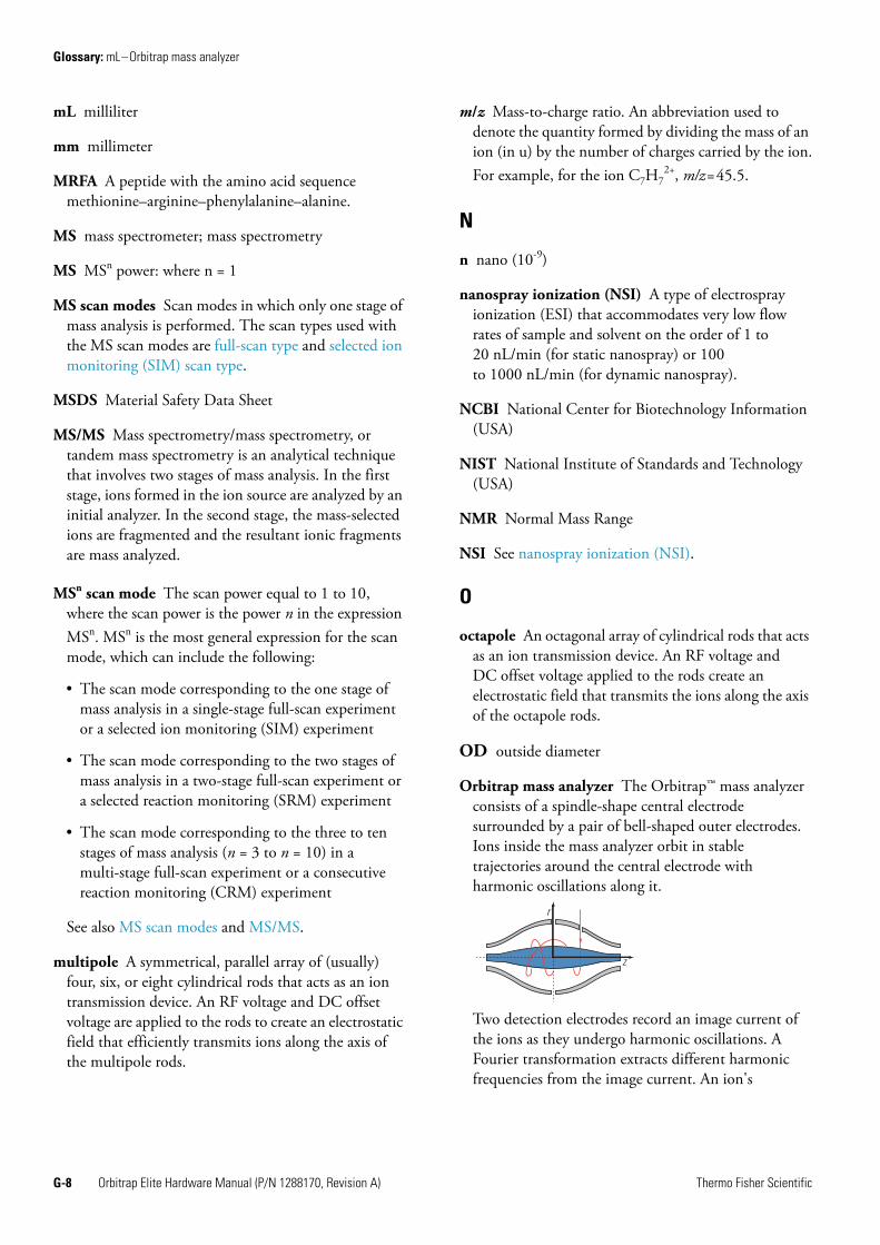
Glossary: mL–Orbitrap mass analyzer
G-8 Orbitrap Elite Hardware Manual (P/N 1288170, Revision A) Thermo Fisher Scientific
mL milliliter
mm millimeter
MRFA A peptide with the amino acid sequence methionine–arginine–phenylalanine–alanine.
MS mass spectrometer; mass spectrometry
MS MSn power: where n = 1
MS scan modes Scan modes in which only one stage of mass analysis is performed. The scan types used with the MS scan modes are full-scan type and selected ion monitoring (SIM) scan type.
MSDS Material Safety Data Sheet
MS/MS Mass spectrometry/mass spectrometry, or tandem mass spectrometry is an analytical technique that involves two stages of mass analysis. In the first stage, ions formed in the ion source are analyzed by an initial analyzer. In the second stage, the mass-selected ions are fragmented and the resultant ionic fragments are mass analyzed.
MSn scan mode The scan power equal to 1 to 10, where the scan power is the power n in the expression MSn. MSn is the most general expression for the scan mode, which can include the following:
• The scan mode corresponding to the one stage of mass analysis in a single-stage full-scan experiment or a selected ion monitoring (SIM) experiment
• The scan mode corresponding to the two stages of mass analysis in a two-stage full-scan experiment or a selected reaction monitoring (SRM) experiment
• The scan mode corresponding to the three to ten stages of mass analysis (n = 3 to n = 10) in a multi-stage full-scan experiment or a consecutive reaction monitoring (CRM) experiment
See also MS scan modes and MS/MS.
multipole A symmetrical, parallel array of (usually) four, six, or eight cylindrical rods that acts as an ion transmission device. An RF voltage and DC offset voltage are applied to the rods to create an electrostatic field that efficiently transmits ions along the axis of the multipole rods.
m/z Mass-to-charge ratio. An abbreviation used to denote the quantity formed by dividing the mass of an ion (in u) by the number of charges carried by the ion.For example, for the ion C7H7
2+, m/z=45.5.
N
n nano (10-9)
nanospray ionization (NSI) A type of electrospray ionization (ESI) that accommodates very low flow rates of sample and solvent on the order of 1 to 20 nL/min (for static nanospray) or 100 to 1000 nL/min (for dynamic nanospray).
NCBI National Center for Biotechnology Information (USA)
NIST National Institute of Standards and Technology (USA)
NMR Normal Mass Range
NSI See nanospray ionization (NSI).
O
octapole An octagonal array of cylindrical rods that acts as an ion transmission device. An RF voltage and DC offset voltage applied to the rods create an electrostatic field that transmits the ions along the axis of the octapole rods.
OD outside diameter
Orbitrap mass analyzer The Orbitrap™ mass analyzer consists of a spindle-shape central electrode surrounded by a pair of bell-shaped outer electrodes. Ions inside the mass analyzer orbit in stable trajectories around the central electrode with harmonic oscillations along it.
Two detection electrodes record an image current of the ions as they undergo harmonic oscillations. A Fourier transformation extracts different harmonic frequencies from the image current. An ion's
r
z
Glossary: OT–retention time (RT)
Thermo Fisher Scientific Orbitrap Elite Hardware Manual (P/N 1288170, Revision A) G-9
mass-to-charge ratio m/z is related to the frequency f of its harmonic oscillations and to the instrumental constant k by:m/z = k/f 2
OT Orbitrap
See Orbitrap mass analyzer.
OVC outer vacuum case
Ω ohm
P
p pico (10-12)
Pa pascal
parent ion An electrically charged molecular species that can dissociate to form fragments. The fragments can be electrically charged or neutral species. A parent ion can be a molecular ion or an electrically charged fragment of a molecular ion. Also called a precursor ion.
parent mass The mass-to-charge ratio of a parent ion. The location of the center of a target parent-ion peak in mass-to-charge ratio (m/z) units. Also known as precursor mass.
See also: parent ion.
PCB printed circuit board
PDA detector Photodiode Array detector is a linear array of discrete photodiodes on an integrated circuit chip. It is placed at the image plane of a spectrometer to allow a range of wavelengths to be detected simultaneously.
PE protective earth
PID proportional / integral / differential
P/N part number
p-p peak-to-peak voltage
ppm parts per million
PQD pulsed-Q dissociation
precursor ion An electrically charged molecular species that can dissociate to form fragments. The fragments can be electrically charged or neutral species. A precursor ion (PR) can be a molecular ion or an electrically charged fragment of a molecular ion. Also known as parent ion.
precursor mass Mass of the corresponding precursor (or parent) ion or molecule.
psig pounds per square inch, gauge
PTM posttranslational modification
pulsed Q dissociation (PQD) Collision-induced dissociation that involves precursor ion activation at high Q, a time delay to allow the precursor to fragment, and then a rapid pulse to low Q where all fragment ions are trapped. The fragment ions can then be scanned out of the ion trap mass analyzer and detected. PQD eliminates the “1/3 Rule” low mass cut-off for MS/MS data.
Q
quadrupole A symmetrical, parallel array of four hyperbolic rods that acts as a mass analyzer or an ion transmission device. As a mass analyzer, one pair of opposing rods has an oscillating radio frequency (RF) voltage superimposed on a positive direct current (DC) voltage. The other pair has a negative DC voltage and an RF voltage that is 180 degrees out of phase with the first pair of rods. This creates an electrical field (the quadrupole field) that efficiently transmits ions of selected mass-to-charge ratios along the axis of the quadrupole rods.
R
RAM random access memory
raw data Uncorrected liquid chromatograph and mass spectrometer data obtained during an acquisition. Xcalibur and Xcalibur-based software store this data in a file that has a .raw file extension.
resolution The ability to distinguish between two points on the wavelength or mass axis.
retention time (RT) The time after injection at which a compound elutes. The total time that the compound is retained on the chromatograph column.
Glossary: RF–SIM
G-10 Orbitrap Elite Hardware Manual (P/N 1288170, Revision A) Thermo Fisher Scientific
RF radio frequency
RF lens A multipole rod assembly that is operated with only radio frequency (RF) voltage on the rods. In this type of device, virtually all ions have stable trajectories and pass through the assembly.
RF voltage An AC voltage of constant frequency and variable amplitude that is applied to the ring electrode or endcaps of the mass analyzer or to the rods of a multipole. Because the frequency of this AC voltage is in the radio frequency (RF) range, it is referred to as RF voltage.
RMS root mean square
ROM read-only memory
rotary-vane pump A mechanical vacuum pump that establishes the vacuum necessary for the proper operation of the turbomolecular pump. (Also called a roughing pump or forepump.)
RS-232 An accepted industry standard for serial communication connections. This Recommended Standard (RS) defines the specific lines and signal characteristics used by serial communications controllers to standardize the transmission of serial data between devices.
RT An abbreviated form of the phrase retention time (RT). This shortened form is used to save space when the retention time (in minutes) is displayed in a header, for example, RT: 0.00-3.75.
S
s second
scan mode and scan type combinations A function that coordinates the three processes in the MS detector: ionization, mass analysis, and ion detection. You can combine the various scan modes and scan types to perform a wide variety of experiments.
selected ion monitoring (SIM) scan type A scan type in which the mass spectrometer acquires and records ion current at only one or a few selected mass-to-charge ratio values.
See also selected reaction monitoring (SRM) scan type.
selected reaction monitoring (SRM) scan type A scan type with two stages of mass analysis and in which a particular reaction or set of reactions, such as the fragmentation of an ion or the loss of a neutral moiety, is monitored. In SRM a limited number of product ions is monitored.
SEM secondary electron multiplier
Serial Peripheral Interface (SPI) hardware and firmware communications protocol
serial port An input/output location (channel) for serial data transmission.
sheath gas The inner coaxial gas (nitrogen), which is used in the API source to help nebulize the sample solution into a fine mist as the sample solution exits the ESI or APCI nozzle.
sheath gas flow rate The rate of flow of sheath gas into the API source. A measurement of the relative flow rate (in arbitrary units) that needs to be provided at the sheath gas inlet to provide the required flow of sheath gas to the ESI or APCI nozzle.
sheath gas inlet An inlet in the API probe where sheath gas is introduced into the probe.
sheath gas plumbing The gas plumbing that delivers sheath gas to the ESI or APCI nozzle.
sheath gas pressure The rate of flow of sheath gas (nitrogen) into the API source. A measurement of the relative flow rate (in arbitrary units) that needs to be provided at the sheath gas inlet to provide the required flow of inner coaxial nitrogen gas to the ESI or APCI nozzle. A software-controlled proportional valve regulates the flow rate.
See also sheath gas.
sheath gas valve A valve that controls the flow of sheath gas into the API source. The sheath gas valve is controlled by the data system.
signal-to-noise ratio (S/N) The ratio of the signal height (S) to the noise height (N). The signal height is the baseline corrected peak height. The noise height is the peak-to-peak height of the baseline noise.
SIM See selected ion monitoring (SIM) scan type.

Glossary: skimmer–vacuum manifold
Thermo Fisher Scientific Orbitrap Elite Hardware Manual (P/N 1288170, Revision A) G-11
skimmer A vacuum baffle between the higher pressure capillary-skimmer region and the lower pressure region. The aperture of the skimmer is offset with respect to the bore of the ion transfer capillary.
source CID A technique for fragmenting ions in an atmospheric pressure ionization (API) source. Collisions occur between the ion and the background gas, which increase the internal energy of the ion and stimulate its dissociation.
SPI See Serial Peripheral Interface (SPI).
SRM See selected reaction monitoring (SRM) scan type.
sweep gas Nitrogen gas that flows out from behind the sweep cone in the API source. Sweep gas aids in solvent declustering and adduct reduction.
See also sweep gas flow rate.
sweep gas flow rate The rate of flow of sweep gas into the API source. A measurement of the relative flow rate (in arbitrary units) to provide the required flow of nitrogen gas to the sweep cone of the API source.
See also sweep gas.
syringe pump A device that delivers a solution from a syringe at a specified rate.
T
T Tesla
target compound A compound that you want to identify or quantitate or that a specific protocol (for example, an EPA method) requires that you look for. Target compounds are also called analytes, or target analytes.
TIC See total ion current (TIC).
TMP See turbomolecular pump.
Torr A unit of pressure, equal to 1 mm of mercury and 133.32 Pa.
total ion current (TIC) The sum of the ion current intensities across the scan range in a mass spectrum.
tube lens offset The voltage offset from ground that is applied to the tube lens to focus ions toward the opening of the skimmer.
See also source CID.
Tune Method A defined set of mass spectrometer tune parameters for the ion source and mass analyzer. Tune methods are defined by using the instrument software’s tune window and saved as tune file.
A tune method stores tune parameters only. (Calibration parameters are stored separately, not with the tune method.)
tune parameters Instrument parameters whose values vary with the type of experiment.
turbomolecular pump A vacuum pump that provides a high vacuum for the mass spectrometer and detector system.
TWA time weighted average
U
u atomic mass unit
UHV ultra high vacuum
ultra-high performance liquid chromatography (U-HPLC) See high performance liquid
chromatography (HPLC).
Ultramark 1621 A mixture of perfluoroalkoxycyclotriphosphazenes used for ion trap calibration and tuning. It provides ESI singly charged peaks at m/z 1022.0, 1122.0, 1222.0, 1322.0, 1422.0, 1522.0, 1622.0, 1722.0, 1822.0, and 1921.9.
UMR Universal Mass Range
V
V volt
V AC volts alternating current
V DC volts direct current
vacuum manifold A thick-walled, aluminum chamber with machined flanges on the front and sides and various electrical feedthroughs and gas inlets that encloses the API stack, ion optics, mass analyzer, and ion detection system.
Glossary: vacuum system–XML (Extensible Markup Language)
G-12 Orbitrap Elite Hardware Manual (P/N 1288170, Revision A) Thermo Fisher Scientific
vacuum system Components associated with lowering the pressure within the mass spectrometer. A vacuum system includes the vacuum manifold, pumps, pressure gauges, and associated electronics.
vent valve A valve that allows the vacuum manifold to be vented to air or other gases. A solenoid-operated valve.
vol volume
W
w width
W watt
WEEE European Union Waste Electrical and Electronic Equipment Directive. Provides guidelines for disposal of electronic waste.
X
XML (Extensible Markup Language) A general-purpose markup language that is used to facilitate the sharing of data across different information systems, particularly via the Internet.
Thermo Fisher Scientific Orbitrap Elite Hardware Manual (P/N 1288170, Revision A) I-1
Numerics00101-08-00006 3-5600101-08500 1-3800101-15500 1-3800101-2500 1-3800109-02-00020 3-5700301-01-0013 4-700301-15517 4-70690280 1-38119265-0003 3-45119283-0001 3-46119683-0100 3-4712 pin feedthrough
harness 3-39location 3-34, 3-37
120320-0030 3-421275730 3-111275740 3-111284050 3-5823827-0008 3-323827-0009 3-332000-60340 3-143814-6530 3-4798000-20060 3-5698000-62006 3-56–3-5798000-62008 4-7, A-1
AA0301-15101 3-5Active Pirani gauge (APG) 1-35active temperature control 1-17actual vial temperature 3-50aluminum oxide abrasive, number 600 3-14analog signals 1-53analyzer
chamber temperature 1-62system 2-10temperature 1-42
angiotensin I 4-7anti-aliasing filters 1-51API source
safety interlock switch 2-10settings 2-13
applicators, cotton-tipped 3-14Automatic Gain Control (AGC) 1-12, 2-15autosampler 2-8–2-9auxiliary gas 1-37
axial ion ejection 1-12axial oscillations 1-15–1-16
Bbakeout
controls 1-6–1-7timer 1-7, 3-4–3-5
bakeout procedureindication 1-7starting 1-6, 3-5stopping 1-6, 3-5
base studs 3-41, 3-43bath gas 1-13bayonet guide 3-30bayonet lock 3-30bayonet pin 3-30buck/boost transformer 1-10burnout, of filament 3-54buttons
Display Status View 2-11On/Standby 2-6system bakeout 1-6
Ccable tie 1-9calibration parameters 2-13CAN bus 1-55cartridge heaters 3-41central electrode
location 1-14power supply box 1-42voltages 1-15, 1-65
central electrode power supply boardcooling 1-17diagnostic LEDs 1-66location 1-59, 1-65
central electrode pulser boarddiagnostic LEDs 1-62location 1-59, 1-61
ceramic lens holder 3-39ceramic spacer 3-41charge-sign independent trapping (CSIT) 1-12, 1-21circuit breakers 1-6–1-7cleaning
instrument surface 3-3ion source block 3-40
Index
I-2 Orbitrap Elite Hardware Manual (P/N 1288170, Revision A) Thermo Fisher Scientific
Index: D–E
ion source lens assembly 3-33ion volume 3-21
CLT compartment 1-30CLT Offset connector 1-59, 1-64CLT RF main board
diagnostic LEDs 1-64, 1-66function 1-13location 1-59, 1-63
CLT RF unit 1-63CLT RF voltage 1-13Cold Ion Gauge 1-30, 1-32, 1-35–1-36, 1-45, 1-48collision gas
C-Trap 1-13HCD 1-13inlet 1-10linear trap 1-38
Communication LED 1-54communication link 1-5condenser filter, of recirculating chiller 3-58connector, to ETD Interface board 1-22control elements
inlet valve 1-22instrument 1-5
control panel 1-6control unit, for turbopumps 1-32Convectron gauge
ETD Module 1-22–1-23, 1-25, 1-35linear trap 1-35
cooling watercircuit 1-17, 1-42flow control sensor 1-42properties 1-43temperature 1-42
cover lid, for bakeout controls 1-7C-Trap
description 1-13gas supply 1-39
cycle time 1-4
Ddata acquisition analog board
diagnostic LEDs 1-51layout 1-50location 1-49, 1-51
data acquisition digital PCI boarddiagnostic LEDs 1-50layout 1-50location 1-49–1-50
data acquisition unit 1-49data communication 1-45data system
communication 1-5, 2-12connection 1-9log file 2-2
DC HV Supply PCB 1-22–1-23, 1-26default values, of tune and calibration parameters 2-13deflector electrode (DE) voltages 1-65Display Status View button 2-11distilled water 3-3drip pan, of ETD forepump 1-34dynamic range, of instrument 1-4
EE-clips 3-39electric power, for recirculating chiller 1-43electrodynamic squeezing 1-15electronic boards
data acquisition analog 1-51data acquisition digital PCI 1-50instrument control 1-52ion optic supply 1-59left side 1-59power distribution 1-53right side 1-46
electronic connections, to linear trap 1-45emergency shutdown 2-2entry housing 3-34error messages 1-36, 1-54, 1-56ETD
main access panel 3-24maintenance 3-12reagent carrier gas supply 1-11
ETD Control PCB 1-22–1-23, 1-25–1-27ETD forepump
cabinet 1-22connections 1-23, 1-34electrical cord 1-34power supply 1-24weight 3-10
ETD Ion Optic Supply board 1-18–1-19, 1-23, 1-46, 1-49ETD Module
forepump receptacle 1-24Heater Control PCB 1-26Interface board 1-23, 1-25ion gauge 1-23location 1-19maintenance 3-12power panel 1-24power receptacle 1-24power supply 1-9power switch 1-24service switch 1-24Standby condition 2-4
ETD power modulefunction 1-23panel 1-23, 1-25
ETD Reagent Kit 4-7ETD side access panel

Thermo Fisher Scientific Orbitrap Elite Hardware Manual (P/N 1288170, Revision A) I-3
Index: F–H
interlocks 3-55removing 3-19
ETD turbopumpconnections 1-23, 1-34controller 1-35function 1-32location 1-22maintenance 3-11
Ethernet 1-9–1-10evacuating, after a complete shutdown 3-4Exactive Installation Kit 1-38exhaust
hose 1-11, 1-34system 1-11, 1-33–1-34
external calibration 1-4external connections 1-10extracting voltage 1-14extraction, of ion packets 1-14
Ffan filters 1-22, 3-57ferrules, tightening 3-56filament
assembly 3-21, 3-42burnout 3-54emission current 3-42function 1-26, 1-28wire 3-44
filter, for cooling water 1-42fingerprints, removing 3-3flatapole 1-32flow control
sensor 1-42UHP nitrogen 1-23, 1-26
flow ratescooling water 1-42HCD collision gas 1-39
flow restrictors 1-29fluid bag filter, of chiller 3-58fluoranthene 4-7, A-1focusing potentials 1-67foreline hose connection 3-34forepump electrical cord 1-34forepumps
cabinet 1-2, 1-6, 1-33effluent 1-33linear trap 1-30–1-31, 1-33location 1-6, 1-12, 1-33oil level 1-33oil mist filters 1-33, 3-11power supply 1-33switches 1-33
forevacuum tube 1-34front panel 1-3
front side, LEDs 1-5FT Electronics switch
functions 1-56location 1-8
fused silica tubingfrom lower oven 3-56from upper oven 3-56in ETD Module 1-29
Ggas ballast 1-33gas pressures 2-10gas supply
C-Trap 1-39helium 1-10nitrogen 1-10schematics 1-37
gas valves 3-56gate voltage 1-60gloves 3-2ground wires 1-46guide bar
function 1-22, 3-34handle 3-23–3-24opening 3-23–3-24, 3-45
Hhandling, hot pump oil 3-10harmonic oscillations, in Orbitrap 1-15hazardous materials 1-33HCD
collision gas port 1-37flow rate, of collision gas 1-39fragment spectra 1-18housing 1-30, 1-32
HCD celldescription 1-18supply voltages 1-46
heated dual restrictor enclosure 1-29heated transfer line 1-29heater control 1-56Heater Control PCB 1-22–1-23, 1-27heater ring 3-41heating element 1-42helium
gas capillary 1-39gas pressure 1-38inlet 1-10, 1-37purging the line 2-11supply 1-10
high voltage power supply boarddiagnostic LEDs 1-68

I-4 Orbitrap Elite Hardware Manual (P/N 1288170, Revision A) Thermo Fisher Scientific
Index: I–L
function 1-13layout 1-67location 1-59, 1-66voltages 1-67
high voltage, at PCBs 1-44
Iimage current 1-15–1-16, 1-48inlet port, for UHP nitrogen 1-22inlet valve
block 3-34knob 3-24, 3-34, 3-45lever 1-22, 3-23–3-24, 3-34, 3-45plug 3-24, 3-34, 3-45seal kit 3-45seal tool 3-46solenoid 1-22, 3-34
installation kit, for the reagent inlet module 3-56instrument
controls 1-6diagnostics 1-44forevacuum measurement 1-35high vacuum measurement 1-35operating voltage 1-9parts 4-2rear side 1-6right side 1-9shutdown 1-53switching off 1-9, 2-2
instrument control boarddiagnostic LEDs 1-53location 1-46, 1-49, 1-52software status LEDs 1-53
internal calibration 1-4internal computer
add-ons 1-50–1-51data communication 1-45location 1-46, 1-49rebooting 2-12timer 1-50
ion dephasing 1-17ion gauge, for ETD Module 1-22ion optic supply board
diagnostic LEDs 1-60location 1-59
ion optics 1-12ion oscillation 1-14ion packets 1-14, 1-16ion source
assembly 3-37block 3-21, 3-39, 3-41, 3-43filament 3-41, 3-43filament assembly 3-42lens assembly 3-39, 3-43lenses 3-21
PCB 3-39, 3-41, 3-43schematics 1-23springs 3-39
ion trajectory 1-14ion volume
alignment arrow 3-30cleaning 3-21key thumbscrew 3-41location 1-23, 1-29temperature 3-28
ion volume assembly, cleaning frequency 3-21ion volume tool
alignment arrow 3-30components 3-23handle 1-22, 3-25usage 3-21, 3-27
ionization techniques 1-12ions
detection 1-16electrodynamic squeezing 1-15image current 1-16packet shape 1-16–1-17
Llaboratory
exhaust system 1-33–1-34gas supplies 1-10ventilation 1-38
LC 2-6–2-7leak checking 1-26, 1-40LEDs
power control 1-7system status 1-5, 1-7vacuum 1-5
left side panel, of instrument 1-3lens voltages 1-66line power 1-9linear trap
collision gas 1-38Communication LED 2-9, 2-12connections 1-53description 1-12electronics 1-45forepumps 1-31, 1-33LEDs 1-5location 1-2, 1-19maintenance 3-1Power LED 2-9, 2-12power panel 1-6, 1-33Reset button 2-12System LED 2-10, 2-12turbopump 1-32Vacuum LED 2-10vacuum measurement 1-35vent valve 1-36, 1-39, 2-2–2-3

Thermo Fisher Scientific Orbitrap Elite Hardware Manual (P/N 1288170, Revision A) I-5
Index: M–P
Link Port Signal line 1-52log file 2-2lower oven 3-56
Mmagnet support 3-21magnet yoke 3-39magnets, in ion source 3-21, 3-39main circuit breaker 2-8main power switch
function 1-9, 1-56location 1-6Off position 2-2securing 1-9status 1-5
main RF supply 1-63mains failure 1-57, 2-2, 3-4mains supply
for ETD Module 1-9for instrument 1-9
maintenanceAPI source 1-12cooling circuit 3-58linear trap 3-1procedures 3-2reagent ion source 3-20recirculating chiller 3-58vacuum system 3-4
mass accuracy 1-4mass range 1-4Material Safety Data Sheet (MSDS) 3-48micro controller 1-52–1-53MS/MS 1-4multiple socket outlets 1-7, 1-56, 2-2
Nnitrogen
CLT 1-37connection to source 1-38cooling gas 1-28gas flow 1-39inlet 1-10pressure 1-39pressure regulator 1-39–1-40supply 1-10tubing 1-39venting 1-37
Ooctapole RF voltages 1-60oil
level 1-33mist filters 1-33–1-34, 3-11
On/Standby button 2-4, 2-6, 3-22operating vacuum 1-5Orbitrap
applied voltages 1-13central electrode 1-61chamber 1-31control LEDs 1-6detection electrodes 1-61differential pumping 1-14electrodes 1-15Instrument Control board 1-23ion extraction 1-14ion trajectories 1-16layout 1-13lenses 1-14measuring principle 1-14–1-15voltages 1-13, 1-16
output current, of preamplifier 1-48
Ppadlock, for main power switch 1-9parameters
calibration 2-13default values 2-13tune 2-13
part numbers 4-1Peltier elements
function 1-17, 1-42, 1-62location 1-42, 1-65temperature 1-63water supply 1-32, 1-48
Penning gauge 1-56peripherals power outlet 1-23–1-24Pirani gauge 1-30–1-31, 1-36, 1-56position, of inlet valve lever 3-34power
connector 1-6, 1-10connector for linear trap 1-12control LEDs 1-8control panel 1-7–1-8panel 1-6supply for linear trap 1-12
power distributionoperating states 1-56resetting 1-36working modes 1-56
power distribution boardcontrol 1-8function 1-42layout 1-54location 1-46, 1-53power supply 1-7, 1-56status LEDs 1-55

I-6 Orbitrap Elite Hardware Manual (P/N 1288170, Revision A) Thermo Fisher Scientific
Index: Q–S
power fail detector 2-3Power LED 1-5power module 1-22power outlet, for peripheral devices 1-9–1-10power supply
data system 1-9ETD Module 1-9
power supply 1 boarddiagnostic LEDs 1-58layout 1-57location 1-46, 1-57
power supply 2 boarddiagnostic LEDs 1-52location 1-49
preamplifiercooling 1-42diagnostic LEDs 1-47, 1-49location 1-32, 1-46, 1-48
pressure readings, in ETD Module 1-35pressure regulator
location 1-40nitrogen 1-39–1-40
preventive maintenance 2-8, 3-2printed circuit boards 1-44proton transfer reactions 1-21pumping, the system 2-9, 3-4pumps
exhaust 1-11forevacuum 1-33manuals 3-5, 3-11oil mist filters 1-33
purging, helium line 2-11
Qquadrupole mass filter 1-21quality, of vacuum 1-53
Rreagent heaters 1-22–1-23, 1-26–1-28reagent inlet cover 3-55reagent inlet source
heating unit 3-51location 3-52
reagent ion sourcecleaning frequency 3-13description 1-28–1-29flow restrictors 3-54maintenance 3-20maintenance tools 3-14
Reagent Ion Source dialog box 1-27, 2-4Reagent Ion Source instrument control icon 2-4, 3-22Reagent Ion Source On check box 1-27–1-28
reagent vapor, in the carrier gas 1-27reagent vials 1-29rebooting, of instrument 2-2recirculating chiller
condenser filter 3-58connections 1-4description 1-43fluid bag filter 3-58maintenance 3-58
reflector DC voltages 1-60removing
ETD main access panel 3-18ETD side access panel 3-19gases 2-10, 3-4stains 3-3
repair covering letter 3-3replacing
chiller operating fluid 3-58filter cartridge 3-58inlet valve components 3-45ion source filament 3-42operating fluid reservoir of turbopumps 3-11reagent vials 3-48turbopump operating fluid 3-11
reservoir, of recirculating chiller 3-58resetting
instrument 2-12system parameters 2-13tune and calibration parameters 2-13
resolution, of instrument 1-4restrictor
oven cover 3-55oven heater 1-26
RF CLT main board 1-66RF off & feedback board 1-59, 1-64RF output control 1-59RF voltage supply 1-63right side panel, of instrument 1-3
Ssafety
features 1-25interlock switch 2-10problem 3-54
sample inlet aperture 3-41secondary electrons 1-26SEM detector 1-12serial port connector 1-53service switch, of linear trap 1-8setting up, conditions for operation 2-10sheath gas 1-37shutdown 1-57, 2-7, 2-9signal communication 1-45software

Thermo Fisher Scientific Orbitrap Elite Hardware Manual (P/N 1288170, Revision A) I-7
Index: T–V
debugging 1-53function 1-42, 1-44status LEDs of the instrument control board 1-53Tune Plus window 2-6
specifications, of instrument 1-4spectrum 1-17SPI bus
function 1-45termination board 1-63–1-64, 1-66, 1-68
spring clip thumb screw 3-39, 3-41stainless steel parts, cleaning 3-14stains, removing 3-3Standby condition 1-28, 2-4starting up
ETD Module 2-11instrument 2-9
status LEDs, of power distribution board 1-55Status View 3-22sweep gas 1-37switches
forepumps 1-33FT Electronics 1-8, 3-4linear trap 1-8main power 1-9vacuum pumps 1-8
switching on, the vacuum system 1-36system
bakeout 1-5–1-6, 1-36, 1-48, 2-9, 3-4bakeout timer 1-6buttons for bakeout 1-6heating 1-36pump down time 2-10rebooting 2-2resetting 2-12shutdown 2-2Standby 2-4starting up 2-9status LEDs 1-5, 1-54timing 1-50venting 1-39, 2-2
system status LEDslinear trap 1-2Orbitrap Elite 1-2
Ttemperature
analyzer chamber 1-62control 1-17differential 1-17monitoring 3-51sensor 3-41
temperature controller boarddiagnostic LEDs 1-63function 1-17layout 1-62
location 1-59, 1-62thermoelectric elements 1-17thumbscrews 3-37, 3-39tools
cleanliness 3-3for cleaning stainless steel parts 3-14for cleaning the ion volume 3-21reagent ion source 3-14
top lidsETD Module 1-3MS 1-3–1-4
transfer chamber 1-12transfer line
bellows 3-37heater 1-26inlet 3-56location 1-23
transfer multipole 1-19–1-21, 1-32trap voltage 1-60triple gas filter 1-41tune parameters 2-13Tune Plus window
buttons 2-6, 2-11diagnostics 1-44
turbopumpsconnections 1-53controllers 1-32, 1-35error 1-55HiPace 300 1-30, 1-37, 1-42HiPace 80 1-30, 1-37, 1-42linear trap 1-32, 1-35maintenance 3-11TMP 1 1-30–1-31TMP 2 1-30–1-32TMP 3 1-31–1-32TMP 4 1-31vent valves 1-36
UUHP nitrogen, inlet port 1-11, 1-40UHV chamber
components 1-31location 1-30temperature control 1-17vacuum 1-31
uninterruptible power supply (UPS) 2-2–2-3upper control panel 1-6–1-7user maintenance 3-1–3-2, A-1
Vvacuum
compartments 1-30deterioration 1-36
I-8 Orbitrap Elite Hardware Manual (P/N 1288170, Revision A) Thermo Fisher Scientific
Index: W–X
failure 1-36, 1-53gauges 1-35, 1-53quality 1-53safety threshold 1-35–1-36system 1-9, 1-30
vacuum chamber 1-30–1-31vacuum components
left instrument side 1-31right instrument side 1-32
Vacuum LEDinstrument 1-5linear trap 2-10
vacuum manifoldlocation 1-22probe plate 3-34–3-35
Vacuum Pumps switch 1-5, 1-8, 1-56vacuum system
controls 1-35heating 1-36moisture 1-36
vent valvecontrol 1-39function 2-2, 2-7linear trap 1-39, 2-3nitrogen supply 1-37
ventilation, in the laboratory 1-38venting pressure 1-40
venting, the system 2-3, 3-19vial heaters
cover 3-51–3-52location 3-53, 3-56ribs 3-53
vial holder 3-52–3-53vial temperature 1-28voltage sags 1-10
Wwater
chiller 1-4, 3-58filter 1-42, 3-58hoses 1-43ports 1-10temperature 1-43
water cooler, for TMP 1-42wheels, of instrument 1-3working modes, of power distribution 1-56working principle, of the Orbitrap 1-3, 1-20
XXcalibur 1-44, 2-15


Thermo Fisher Scientific Inc.
81 Wyman Street
P.O. Box 9046
Waltham, Massachussetts 02454-9046
United States
www.thermoscientific.com
Part of Thermo Fisher Scientific