Orbit Man26 1327 User Guide
116
AL-7103-Ku Mk II 1.15m (45”) Ku-Band Antenna Stabilized Marine Satellite Communication System User and Installation Guide Document: MAN26-1327 Revision : -
Transcript of Orbit Man26 1327 User Guide

AL-7103-Ku Mk II
1.15m (45”) Ku-Band Antenna
Stabilized Marine Satellite Communication System
User and Installation Guide
Document: MAN26-1327 Revision : -

AL-7103- Ku Mk II User & Installation Guide Rev: - ii
Copyright © 2006 Orbit-Alchut Technologies Ltd. All rights reserved.
All product names are trademarks of the Orbit-Alchut Technologies Ltd.
Other names are the property of the respective owners.
No part of this publication may be reproduced, transmitted, transcribed, stored in a retrieval system, or translated into any language or computer language, in any form or by any means, electronic, mechanical or otherwise without prior written permission of the Orbit-Alchut Technologies Ltd.
Disclaimer of Warranty
The Orbit-Alchut Technologies Ltd has made every effort to ensure the accuracy and relevancy of the material in this document. It is expected that all sections of this document will be read thoroughly and that all information and procedures should be fully understood. However, the group assumes no responsibility for any errors that may have been included in this document, and reserves the right to make changes to the document without notice.
The Orbit-Alchut Technologies Ltd makes no warranty of any kind in regard to this document including, but not limited to, the implied warranties of merchantability and fitness for a particular purpose.
The Orbit-Alchut Technologies Ltd disclaims any responsibility for incidental or consequential damages in connection with the furnishing, performance, or use of this document.
Parts of this document may be based on hardware or software developed by third-party vendors. The Orbit-Alchut Technologies Ltd disclaims any responsibility for the accuracy of this document with respect to such hardware and software, and assumes no responsibility for incidental or consequential damages arising due to discrepancies between this document and such hardware or software.

AL-7103- Ku Mk II User & Installation Guide Rev: - iii
Revision History & Control Revision History
Revision # Date Description Rev: - October 2006 Initial version
List of Effective Pages
TOTAL NUMBER OF PAGES IN THIS PUBLICATION IS 116 CONSISTING OF THE FOLLOWING:
Page No. Issue
Title.........................................................................................Revision -
i – x .........................................................................................Revision -
1 – 106 ....................................................................................Revision -

AL-7103- Ku Mk II User & Installation Guide Rev: - iv
Safety Precautions The following general safety information is for installing, operating, and servicing the system.
Specific warnings and cautions will be found throughout the manual where they apply, but may not appear in this summary. Observe the following list of safety precautions when installing, operating and maintaining the System:
♦ Keep well clear of the moving Antenna, at all times.
♦ The Antenna Pedestal is equipped with high torque motors that develop considerable forces. These forces can be harmful.
♦ This equipment contains potentially harmful voltages when connected to the designated power sources. Never remove equipment covers except for maintenance or internal adjustments.
♦ Before removing the covers of any unit, verify that the CCU POWER switch is in the OFF position.
♦ Metal parts accessible to the operator are connected to the chassis’ ground to prevent shock, and similar hazards. The chassis’ ground conductor must not be removed. Ensure the enclosure is at ground potential.
♦ Only qualified and trained personnel should perform installation, operation and maintenance of this equipment.
♦ Although the Radome is not heavy, care should be taking when lifting it since it act as sail during windy conditions. At least two people should handle the Radome during installation.
♦ To prevent shock or fire hazard, when sub-units are open or cables disconnected, do not expose the equipment (with the exception of the Radome) to rain or moisture.
♦ Avoid making unauthorized modifications to the circuitry. Any such changes to the system will void the warranty.
♦ Do not disconnect cables from the equipment while the system is powered-on.
• Interfacing this equipment requires the use of high quality connectors and cables.
• Use only ORBIT authorized parts for repair.

AL-7103- Ku Mk II User & Installation Guide Rev: - v
About this Manual This manual is designed to guide you through the operating and installation procedures for the AL-7103-Ku Mk II system.
Conventions Used in this Manual This text style…
Identifies… Example
Text Normal descriptive text.
Text Emphasized text.
Text/Text Words or figures that appear on the screen or that should be typed, or a key to be pressed < >. The name of a file or directory.
400
TEXT The name of a software or hardware component.
ANTENNA
The description of a procedure. To configure…
Notations in this Manual
This information is important and should be noted.
Information given in this message warns of a hazard.
Information given in this warning refers to the only safe method of installation or operation and must be adhered to.

AL-7103- Ku Mk II User & Installation Guide Rev: - vi
Acronyms & Abbreviations ADE
ADMx
BDE
BDMx
BUC
B/W
CCU
IMU
KB
LNA
LNB
M&C
Mk
MMI
MUX
PSU
RJ
SBC
SDM
SR
Above Deck Equipment
Above Deck MUX
Below Deck Equipment
Below Deck MUX
Block Up Converter
Band Width
Central Control Unit
Inertial Measurement Unit
Keyboard
Low Noise Amplifier
Low Noise Block
Monitor & Control
Mark
Man-Machine Interface
Multiplexer
Power Supply Unit
Rotary Joint
Single Board Controller
Servo Drive Module
Slip Ring

AL-7103- Ku Mk II User & Installation Guide Rev: - vii
Table of Contents
About this Manual .....................................................................................................v Conventions Used in this Manual ........................................................................................ v Notations in this Manual ..................................................................................................... v Acronyms & Abbreviations.................................................................................................. vi
1 Overview ..............................................................................................................1 1.1 Introduction ...............................................................................................................1 1.2 System Architecture ...................................................................................................1 1.3 System Key Features ..................................................................................................3
2 System Description.............................................................................................4 2.1 Main System Components ..........................................................................................4
2.1.1 Introduction ...................................................................................................................................... 4 2.1.2 Above Deck Equipment (ADE)......................................................................................................... 4
Radome and Radome Base .........................................................................................8 Pedestal....................................................................................................................10 Servo Drive Modules (SDMs).....................................................................................11 Single Board Controller (SBC)...................................................................................12 Power Supply Unit (PSU) ..........................................................................................14 GPS Antenna............................................................................................................14 Inertial Measurement Unit (IMU) ..............................................................................15 Antenna and RF Front-end Assembly .......................................................................15 RF Package...............................................................................................................16 Low Noise Block (LNB)..............................................................................................17 Block-Up-Converter (BUC)........................................................................................17 Splitter .....................................................................................................................19 DC Inserter ..............................................................................................................19 Above Deck Mux (ADMx) ..........................................................................................20 ADE Power Connection Box......................................................................................21
2.1.3 Below Deck Equipment (BDE) ....................................................................................................... 22 Central Control Unit (CCU).......................................................................................22 Modem and Distribution Array .................................................................................26
2.2 Block Diagram Description.......................................................................................27 2.2.1 Overall System Description............................................................................................................ 27 2.2.2 ADE-BDE Link (ADMx/BDMx Modules) ......................................................................................... 31

AL-7103- Ku Mk II User & Installation Guide Rev: - viii
2.3 ADE Interconnections and Cables ............................................................................33 2.4 System Technical Specifications ...............................................................................35
2.4.1 Weight............................................................................................................................................ 35 2.4.2 Packaging ...................................................................................................................................... 35 2.4.3 Radome ......................................................................................................................................... 35 2.4.4 CCU Interfaces............................................................................................................................... 35 2.4.5 CCU Power Requirements............................................................................................................. 35 2.4.6 Antenna System............................................................................................................................. 35 2.4.7 Frequency Operation ..................................................................................................................... 35 2.4.8 Gain ............................................................................................................................................... 35 2.4.9 LNBs .............................................................................................................................................. 36 2.4.10 Range of Motion............................................................................................................................. 36 2.4.11 Ship Motion .................................................................................................................................... 36 2.4.12 Electrical Interfaces........................................................................................................................ 36
Power Requirements:................................................................................................36 L-band: ....................................................................................................................37 GPS out:...................................................................................................................37 NBR Bandwidth:.......................................................................................................37
2.4.13 Environmental Conditions for Above Deck Equipment (ADE) ........................................................ 37
3 Principles of Operation.....................................................................................38 3.1 Acquisition and Tracking Algorithm..........................................................................38 3.2 Modes of Operation ..................................................................................................40 3.3 Tracking Receiver Feedback .....................................................................................40 3.4 Satellite Validation ...................................................................................................41
3.4.1 Introduction .................................................................................................................................... 41 3.4.2 IRD Lock ........................................................................................................................................ 41 3.4.3 NBR Lock....................................................................................................................................... 42
L-Band Power Detector.............................................................................................42
4 Getting Started - Basic System Operation ......................................................44 4.1 System Start-Up.......................................................................................................44 4.2 Basic Operation Screen ............................................................................................45 4.3 Selecting a Satellite and Channel .............................................................................46 4.4 Moving the Antenna using Manual Mode..................................................................53 4.5 Restarting the System ..............................................................................................54
AL-7103- Ku Mk II User & Installation Guide Rev: - ix
4.6 Manual Setting of Heading .......................................................................................55 4.7 Activating Step-Track Mode......................................................................................56 4.8 Stow the System.......................................................................................................57 4.9 Manual Setting of GPS Lat/Long Location ................................................................58 4.10 Clear GPS..............................................................................................................59 4.11 Setting AGC Threshold ..........................................................................................60 4.12 Viewing Software Version Details...........................................................................61 4.13 Using Host Menu...................................................................................................62 4.14 Replacing the LNB.................................................................................................64
5 Error Messages & Troubleshooting.................................................................65 5.1 Error Messages.........................................................................................................65 5.2 Basic Troubleshooting ..............................................................................................71
6 Concise Installation Guide ...............................................................................72 6.1 Preparing the Installation Site & Unpacking the System...........................................72
6.1.1 Above-the-Deck Installation Considerations .................................................................................. 72 6.1.2 Unpacking the System ................................................................................................................... 72 6.1.3 Shipping Crate Content.................................................................................................................. 73 6.1.4 Unpacking and Visual Inspection ................................................................................................... 74
6.2 Installing the ADE ....................................................................................................76 6.2.1 Introduction .................................................................................................................................... 76 6.2.2 Lifting and Mounting Procedure ..................................................................................................... 79 6.2.3 ADE Cables Connections............................................................................................................... 83
Introduction .............................................................................................................83 Preparing the Radome Pass-Thru Opening ...............................................................83 ADE Power Cable Connection ...................................................................................85 ADE-BDE Cable Connection.....................................................................................86
6.3 Installing the BDE....................................................................................................87 6.3.1 CCU and Modem Installation ......................................................................................................... 87 6.3.2 Connecting CCU Cables ................................................................................................................ 88
CCU Rear-Panel Connectors Overview ......................................................................88 General-Purpose Connections (Power, LAN Jumper, KB, Mouse) ..............................90 ADE-BDE Cable Connection.....................................................................................91 Serial Communication and Compass Connectors .....................................................92 NMEA-0183 RS-422 Compass Connection................................................................94 Step-by-Step Compass connection............................................................................95

AL-7103- Ku Mk II User & Installation Guide Rev: - x
Synchro Compass connection...................................................................................96 IRD LOCK Connection ..............................................................................................97 External AGC Connection.........................................................................................98 RS-232 Channel Connection ....................................................................................99
6.4 Modem Integration (Rx & Tx Path Gain Calculation) ...............................................100 6.4.1 Introduction .................................................................................................................................. 100 6.4.2 Rx Chain Gain Budget (from LNB to Rx Modem Input)................................................................ 100 6.4.3 Tx Chain Gain Budget (from the modem to the BUC input) ......................................................... 101
Coarse Adjustment.................................................................................................101 Fine adjustment model output level (using the HUB station) ..................................101
7 Appendix A – Installation Addendum............................................................103 7.1 Preparing the ADE-BDE Cable................................................................................103
7.1.1 EZ-400-NMH Connector Installation Procedure on LMR-400 ...................................................... 103
AL-7103- Ku Mk II User and Installation Guide Rev: - 1
1 Overview
1.1 Introduction The AL-7103-Ku Mk II system is a Stabilized Marine Communication System, carrying a dual-offset, 1.15m (45”) Tx/Rx Ku-Band composite material antenna, housed inside a low-loss 1.28m (50”) Radome.
The system is designed to maintain, at all times, an accurate look angle of a high-efficiency linear-polarized satellite communication antenna towards a pre-selected geo-stationary communication satellite, while the platform on which it is mounted rocks and rolls on the ocean waves, in any relevant geographical location on the Globe: +75 to –75 deg Latitude.
The look angle is maintained in three angular dimensions with respect to the satellite: Azimuth, Elevation and Polarization Skew.
All the above is to allow a continuous two directional Tx/Rx satellite communication data link brought to life by one of the industry standard satellite digital communication modems, able to interface with the signals produced by the AL-7103-Ku Mk II antenna on L-Band frequency band from one hand, and the user data network from the other.
The satellite modem is not part of the AL-7103-Ku Mk II system and is normally provided by the customer or system integrator.
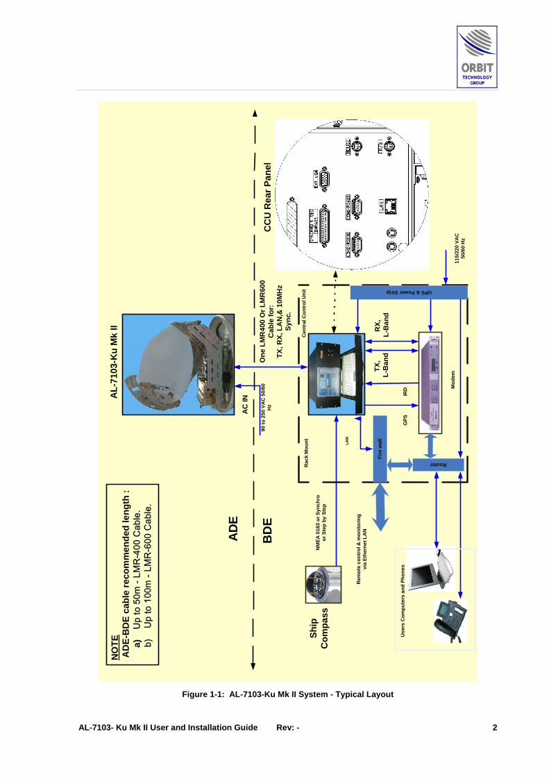
1.2 System Architecture The AL-7103-Ku Mk II system is comprised of equipment mounted both above decks (Above Deck Equipment - ADE) and below decks (Below Deck Equipment - BDE).
The ADE includes pedestal, antenna, RF package, controller, power supply, installed inside a weather-proof radome.
The BDE includes the Central Control Unit (CCU) that serves both as the system’s Man-machine interface and as interface to the ships Gyrocompass as well as the customer’s modem L-Band Tx/Rx.
The connection between ADE and BDE is by a single coaxial cable multiplexing L-Band Tx/Rx and Ethernet LAN control.
Both above decks and below decks equipment are fed by AC mains power
The system functional layout is illustrated in the following Figure.
AL-7103- Ku Mk II User and Installation Guide Rev: - 2
AD
E
BD
E
TX,
L-B
and
RX,
L-B
and
One
LM
R40
0 O
r LM
R60
0C
able
for:
TX, R
X, L
AN
,& 1
0MH
zSy
nc.
Ship
Com
pass
AC
IN
CC
U
NO
TE A
DE-
BD
E ca
ble
reco
mm
ende
d le
ngth
:
a)
Up
to 5
0m -
LMR
-400
Cab
le.
b
) U
p to
100
m -
LMR
-600
Cab
le.
AL-
7103
-Ku
Mk
II
CC
U
CC
U R
ear P
anel
90 to
250
VA
C 5
0/60
Hz
NM
EA 0
183
or S
ynch
roor
Ste
p by
Ste
p
IRD
Rac
k M
ount
Fire
wal
l
LAN
GPS
Router
Mod
em
Cen
tral
Con
trol
Uni
t UPS & Power Strip
Use
rs C
ompu
ters
and
Pho
nes
Rem
ote
cont
rol &
mon
itorin
gvi
a Et
hern
et L
AN
115/
220
VAC
50/6
0 H
z
Figure 1-1: AL-7103-Ku Mk II System - Typical Layout

AL-7103- Ku Mk II User and Installation Guide Rev: - 3
1.3 System Key Features ♦ Exclusive mechanical design, compact dimensions.
♦ Providing up to 1 Mbps transmit data rate (typical values, varies with actual satellite) in an unmatched performance ratio.
♦ Satellite automatic tracking capabilities, based on geographic position data received from system’s GPS, and Ship’s heading data received for the compass (either Ship’s or dedicated compass).
♦ Extremely high efficient antenna-to-radome size ratio.
♦ Unique POL. over X over Y over Azimuth configuration, allowing full hemispherical coverage with no “keyholes” at horizon and Zenith.
♦ Eutelsat Approval for Antenna and RF Sub System.
♦ Built in Narrow Band receiver (NBR).
♦ IRD Interface to Modem.
♦ ADMx (Above Deck Mux) and BDMx (Below Deck Mux), used to transfer RF & Data between the ADE to the BDE via a single coaxial cable only.
♦ Plug & Play Installation.
♦ Easy maintenance, use of modular LRUs (field replaceable).
♦ Built in Satellite database, Maintenance and data logging features.
♦ Remote control and monitoring via Ethernet LAN.
AL-7103- Ku Mk II User and Installation Guide Rev: - 4
2 System Description
2.1 Main System Components
2.1.1 Introduction The AL-7103-Ku Mk II system components are divided into two groups:
♦ Above Deck Equipment (ADE)
♦ Below Deck Equipment (BDE).
2.1.2 Above Deck Equipment (ADE) The ADE includes the following main assemblies and units:
♦ 1.28m (50 “) Radome and Radome Base
♦ Four-axes pedestal
♦ Servo drive modules (SDM) – one per axis
♦ Pitch/Roll sensor and short term Yaw (Inertial Measurement Unit-IMU)
♦ GPS Omni antenna
♦ 1.15m (45”) Composite material Ku-Band Tx/Rx Antenna, Linear Polarization
♦ Power Supply Unit (PSU)
♦ Tracking Single Board Controller (SBC), including a Narrow Band receiver (NBR) & GPS receiver
♦ RF Package – Including 4W/8W BUC, and RF front end, (OMT, Filter, LNB)
♦ BDMx, part of the ADMx / BDMx Link Sub system.
The following Figures show the location of the ADE assemblies and units (Radome removed).
The subsequent paragraphs provide brief technical description of each unit.

AL-7103- Ku Mk II User and Installation Guide Rev: - 5
Figure 2-2: Above Deck Equipment (ADE) – sheet 1 of 3
X-Axis SDM
Radome Base
RF Package
Antenna Reflector
IMU
Azimuth-Axis SDM
PSU
SBC

AL-7103- Ku Mk II User and Installation Guide Rev: - 6
Figure 2-3: Above Deck Equipment (ADE) – sheet 2 of 3
Base Hatch
Mains Power Connection
GPS Antenna

AL-7103- Ku Mk II User and Installation Guide Rev: - 7
Figure 2-4: Above Deck Equipment (ADE) – sheet 3 of 3
ADMx
Y-Axis SDM

AL-7103- Ku Mk II User and Installation Guide Rev: - 8
Radome and Radome Base The ADE assemblies and units are enclosed within a 1.28 m (50”) Radome, mounted on the Radome’s base.
The Radome covers and protects the complete ADE. A service hatch at the radome’s base provides access for maintenance tasks.
Figure 2-5: ADE Radome Outline Dimensions

AL-7103- Ku Mk II User and Installation Guide Rev: - 9
Figure 2-6: ADE Radome – General Views
Figure 2-7: Radome Base Service Hatch

AL-7103- Ku Mk II User and Installation Guide Rev: - 10
Pedestal The Y-over-X-over-Azimuth Pedestal carries and moves the antenna to the required position.
The pedestal axes are not orthogonal. The relative notation angles between the axes are set to produce the tightest packaging factor possible: a 1.12m by 1.19m antenna is packed in a 1.28m radome.
The pedestal is mounted on the Radome Base using shock absorbers.
The pedestal axes are as follows:
♦ Azimuth Axis – provides continuous unlimited 360° rotation. The Azimuth axis includes a Single channel Rotary Joint as well as multiple slip-rings assembly.
♦ X Axis – provides 350 degrees of free rotation (-175° ÷ +175°).
♦ Y Axis – provides 350 degrees of free rotation.
The above axes are driven by identical Servo Drive Modules (SDMs).
In addition to these axes, a fourth Polarization Axis provides two discrete polarization positions: 0° or 90°.
The three axes and their range of angular movement together with the fact that there is a mechanical switch for the antenna polarization, allow pointing of the antenna towards the satellite in more then one possible axes angular location combination.
Actually eight different axes combinations are possible for every look angle of the antenna. The system controller (SBC) selects the best possible combination before each pointing command, so as to allow continuous pointing towards the satellite for all specified sea conditions without going into mechanical limits or geometrical keyholes.
Figure 2-8: Pedestal Axes
X Axis
Y Axis
Polarization Axis
Azimuth Axis

AL-7103- Ku Mk II User and Installation Guide Rev: - 11
Servo Drive Modules (SDMs) Each one of the Azimuth, X, and Y axes is equipped with an identical Servo Drive Module, which acts as a full self-contained turntable that rotates the axis.
Each SDM contains the following assemblies:
♦ Integral Stepper Motor
♦ Stepper driver with 1:16 micro-step control capability
♦ Back-EMF Over-voltage protection card
♦ Dynamic-brakes relay, applying the axes brakes when there is no power
♦ 1:1 Absolute17-bit resolution Encoder
♦ 1:60 reduction gear.
Figure 2-9: Servo Drive Module (SDM)

AL-7103- Ku Mk II User and Installation Guide Rev: - 12
Single Board Controller (SBC) The Single Board Controller (SBC) is a real-time tracking controller, based on an industry-standard CPU with on-board Flash and SDRAM memory that controls system operation according to CCU commands and system modes.
The SBC interfaces with the ADE components via its front-panel connectors.
The SBC runs a Real-Time OS reading all system sensors, performing 3D mathematical transformations, controlling (in closed position and velocity loops) the movement of the axes and providing on-line communication to the Below-decks Central Control Unit (CCU) by the means of standard Ethernet-LAN connection
The SBC is fed by +24VDC and incorporates an internal DC-DC power supply providing +5, +12 and –12VDC voltage to its internal circuits.
The SBC also incorporates a Wide-band as well as Narrow-band Tracking receiver for Step-track feedback.
CCU-SBC Operational Concept:
The operation of the system is fully controlled from the CCU. Using the CCU, the operator may select the desired satellite and channel from a list displayed on the CCU monitor.
The system automatically extracts the desired satellite information using the satellite database, acquires it and tracks the selected satellite by pointing the antenna towards the satellite, while compensating for the platform pitch, roll and yaw movements.
The SBC and CCU provide distributed control concept – SBC running real-time software for stabilization and control, while the CCU presents the man-machine interface to the operator.

AL-7103- Ku Mk II User and Installation Guide Rev: - 13
Figure 2-10: SBC, PSU and GPS Antenna Location
Figure 2-11: SBC Connectors
PSU
SBC
GPS Antenna

AL-7103- Ku Mk II User and Installation Guide Rev: - 14
Power Supply Unit (PSU) The PSU is an AC to DC Power Supply Unit, which converts the AC mains input voltage (90-260 VAC, 50/60 Hz) to DC voltages, distributed to the system components.
The AC mains input voltage, connected to the ADE, is fed via the Azimuth axis slip-ring to the PSU. The unit is contains two industry-standard 150W modules, one producing 24VDC and the other 51VDC.
The 24V output is (SBC-PWR Connector) used to feed the SBC and the BUC, while the 51V (PED-PWR) output is used to drive the SDM motors.
Figure 2-12: Power Supply Unit (PSU) Connectors
GPS Antenna The GPS antenna is connected to the SBC, which contains a GPS receiver.
Figure 2-13: GPS Antenna

AL-7103- Ku Mk II User and Installation Guide Rev: - 15
Inertial Measurement Unit (IMU) A strap down, solid state Inertial Measurement Unit (IMU) provides accurate dynamic readings of the antenna platform roll, pitch, and yaw angles.
During operation, the Inertial Measurement Unit (IMU), installed inside the pedestal, provides the SBC with extremely accurate information on platform’s motion:
♦ Pitch, Roll – measured by two rate-gyro sensors (short-term information) and two inclinometers (long-term information). The Pitch and Roll short-term data is integrated with the long-term data to provide a smooth and stable signal for antenna stabilization.
♦ Yaw variations – measured by a rate-gyro sensor (short-term information). The Yaw short-term data is integrated with the long-term Yaw data received from the ship’s gyrocompass.
Figure 2-14: Inertial Measurement Unit (IMU)
Antenna and RF Front-end Assembly The dual-offset, high efficiency, Gregorian 1.15m (45”) composite material antenna, is installed on the Y axis, and carries the Tx/Rx Ku-Band RF front end and a mechanical Linear Polarization switch.
Figure 2-15: Antenna Reflector and RF Front-End

AL-7103- Ku Mk II User and Installation Guide Rev: - 16
RF Package
The RF Package, mounted on the antenna reflector, includes the following components:
♦ 4W/8W BUC
♦ RF front end:
♦ OMT
♦ Rx and Tx Reject Filters
♦ LNB
♦ Polarizer
♦ Splitter
♦ DC Inserter.
Figure 2-16: RF Package
BUC
OMT
LNB
Polarizer Motor
Tx Reject Filter
Rx Reject Filter

AL-7103- Ku Mk II User and Installation Guide Rev: - 17
Low Noise Block (LNB)
The system is supplied with 1-of-3 available Ku-Band PLL LNBs, covering the following Bands:
♦ 10.95 to 11.70 GHz
♦ 11.70 to 12.20 GHz
♦ 12.25 to 12.75 GHz.
The LNB can be easily replaced to match the required frequency range.
Figure 2-17: Ku-Band LNB
Block-Up-Converter (BUC) ♦ The system is supplied with 4W, or 8W Ku-Band BUC (Block-Up-
Converter), which serves as the system’s RF transmitter.
♦ The BUC Up converts and amplifies the IF signal origin from the Modem. The BUC is powered by the DC Inserter unit, which receives 24 VDC from the PSU unit and supplies BUC operating voltage.
♦ The BUC is suitable for both data and voice communication operating in different modulation formats including BPSK, QPSK, QAM and FM.
♦ The Ku-Band BUC comprises of Up-Converter, Solid State Power Amplifier, Phase Locked Oscillator and DC-DC power converter. It employs L-Band IF interface to the indoor unit.
♦ Choosing the Appropriate BUC:
♦ Required Bandwidth - The smaller the bandwidth - less power required.
♦ Geographic Location - The closer the system is to the equator – less power is required.
♦ Power Limitations - 4W BUC can hold up to 512Kbps with relative efficient SNR; Higher Band Width requires 8W BUC.

AL-7103- Ku Mk II User and Installation Guide Rev: - 18
Figure 2-18: 8W BUC
Figure 2-19: 4W BUC
Figure 2-20: BUC – Typical Functional Block Diagram

AL-7103- Ku Mk II User and Installation Guide Rev: - 19
Splitter The splitter is used to split the LNB output signal between the ADMx and the tracking receiver in the SBC.
Figure 2-21: Splitter
DC Inserter The DC inserter is used to feed 24VDC power supply voltage into the BUC.
Figure 2-22: DC Inserter

AL-7103- Ku Mk II User and Installation Guide Rev: - 20
Above Deck Mux (ADMx) The ADMx (mounted on the pedestal) and the BDMx (inside the BDE CCU) multiplexer modules are used to establish a link between the ADE and BDE, which minimizes the required cabling and uses only a single coax cable (LMR-400 or LMR-600 cable, depending on cable length).
The ADMx also provides amplification of the Tx and RX paths.
Figure 2-23: ADMx

AL-7103- Ku Mk II User and Installation Guide Rev: - 21
ADE Power Connection Box The ADE is fed with mains AC power, connected to the Power Box.
(1) AC Input
(2)Utility
Outlets
(3) SystemPower Switch
Figure 2-24: ADE Power Connection Box
AL-7103- Ku Mk II User and Installation Guide Rev: - 22
2.1.3 Below Deck Equipment (BDE)
Central Control Unit (CCU) The Central Control Unit serves both as the AL-7103 system Man-machine terminal as well as the interface to the ships Gyrocompass and the customer’s modem L-Band Tx/Rx.
The CCU provides host-computer control via Ethernet communication link. Operating under a Windows operating system, the CCU uses the MtsLink software to control and monitor the system.
The CCU is based on a 19” rack-mounted 5U industrial PC (including a 1U keyboard-and-mouse drawer), and it is usually located in the Radio Room or the TV Distribution Room.
The front panel includes a TFT screen, and together with an external keyboard (mounted on a dedicated drawer), they both provide convenient Man-Machine Interface (MMI) with the CCU.
The rear panel includes several connectors, which are used for interface with the ADE, with the modem, and with the ship/vessel, e.g. interface to ship gyro compass (NMEA-0183, Synchro & S.B.S).
The CCU contains the BDMx module, which provides single-cable interface with the ADMx.
The CCU is also able to provide on-line GPS info to the satellite modem, if needed.
The following Figures provide external and internal views of the CCU.

AL-7103- Ku Mk II User and Installation Guide Rev: - 23
Figure 2-25: CCU General View
Figure 2-26: CCU Front Panel
Keyboard
Keyboard Drawer
TFT Screen
POWER Switch
USB Connector

AL-7103- Ku Mk II User and Installation Guide Rev: - 24
Figure 2-27: CCU Rear Panel
Figure 2-28: CCU Internal View
BDMx
Power Supply
Main Board
Mains Power Inlet
Interface Connectors
Screen Board

AL-7103- Ku Mk II User and Installation Guide Rev: - 25
Figure 2-29: BDMx Assembly (Inside the CCU)

AL-7103- Ku Mk II User and Installation Guide Rev: - 26
Modem and Distribution Array The modem provides all the functionality required to transmit /receive data in L-band, and can connect to a HUB, Router or Switch (depending on the Modem type).
The modem and distribution array items are supplied and installed by a third-party, therefore, they are not described in this manual.

AL-7103- Ku Mk II User and Installation Guide Rev: - 27
2.2 Block Diagram Description
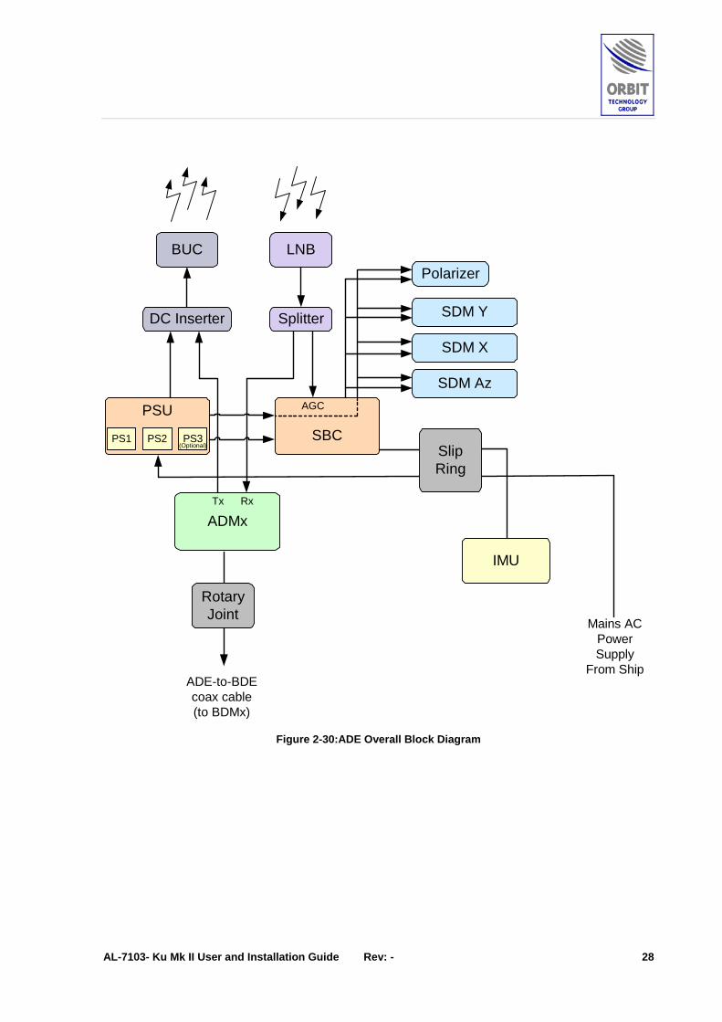
2.2.1 Overall System Description The System is divided to the Above Deck Equipment (ADE) contained inside a Radome, and the Below Deck Equipment (BDE) that includes a Control computer (CCU) that provides a Man Machine Interface to the ADE. The CCU is connected to the compass and the satellite modem (provided by the customer).
The following Figures provide several levels of the system’s block diagram:
♦ ADE Overall Block Diagram
♦ ADE Power Distribution Block Diagram
♦ ADMx-BDMx Link
AL-7103- Ku Mk II User and Installation Guide Rev: - 28
Polarizer
ADMx
PSU
SDM X
SDM Az
SDM YSplitterDC Inserter
BUC LNB
SBCPS1 PS2 PS3(Optional)
Tx Rx
AGC
IMU
Mains ACPowerSupply
From Ship
SlipRing
RotaryJoint
ADE-to-BDEcoax cable(to BDMx)
Figure 2-30: ADE Overall Block Diagram

AL-7103- Ku Mk II User and Installation Guide Rev: - 29
SBC
SDM X
SDM Az
SDM Y
DC Inserter
BUCPSU
PS124 VDC
PS251 VDCFilter
90-220 VAC
51 VDC
PolarizerSwitch Motor
From Ship
PS3(Optional)
24 VDC
RotaryJoint
Figure 2-31: Power Distribution Block Diagram
Slip Ring
AL-7103- Ku Mk II User and Installation Guide Rev: - 30
ADE
BDE
Rack MountAL-7103-CCU
Modem
Single Coax Cable:Up to 50m - LMR-400 .Up to 100m - LMR-600 .
BDMx
ADMx
TX
RX
Figure 2-32: ADMx-BDMx Link Block Diagram

AL-7103- Ku Mk II User and Installation Guide Rev: - 31
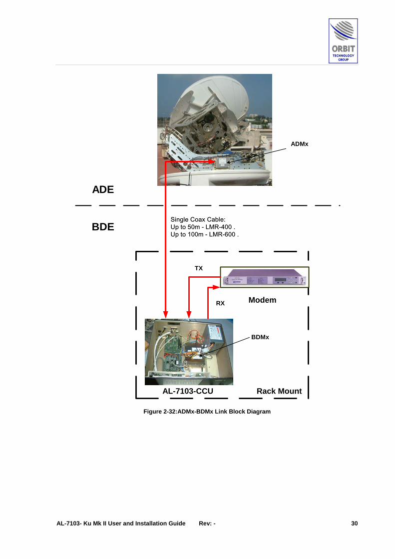
2.2.2 ADE-BDE Link (ADMx/BDMx Modules) The ADMx and the BDMx multiplexer modules are used to establish an ADE-to-BDE link that minimizes the required cabling and uses only a single coax cable (LMR-400 or LMR-600 cable, depending on cable length), carrying the following multiplexed signals:
♦ Modem L-Band Rx
♦ Modem L-Band Tx
♦ Modem 10 MHz Sync to the BUC (and to the LNB, if required)
♦ CCU to SBC LAN connection for monitoring and control (M&C)
Altogether the single coax holds 10 MHz to 4.7 GHz bandwidth.
Both above decks (ADMx) and below decks (BDMx) multiplexers have integral amplification, making it possible to receive antenna signals on the optimal level on the modem L-Band Rx input, from one hand, while having full control over the BUC power from the other hand.
The ADE-BDE Interconnection is designed for best performance when using a Times LMR-400 type of cable for lengths of up to 50m and LMR-600 type of cable for lengths of up to 100m.
The following Figure depicts the ADMx-BDMx link, including the various signals that are multiplexed and carried between the ADE and BDE.
The Link gain values are as follows:
• Tx Path from modem to BUC – 17 dB, min.
• Rx Path from LNB to Modem – 25 dB, min.
Figure 2-33: ADMx and BDMx Units

AL-7103- Ku Mk II User and Installation Guide Rev: - 32
Figure 2-34: ADMx-BDMx Link

AL-7103- Ku Mk II User and Installation Guide Rev: - 33
2.3 ADE Interconnections and Cables The AL-7103 ADE wiring is comprised of the following:
• Main Control harness connecting the SBC with all three SDMs
• Rx Coaxial path connecting the LNB to the ADMx and the SBC
• Tx Coaxial path connecting the BUC to the ADMx
• Single Channel Rotary Joint passing on the ADE-BDE connection to the ADMx
• Multiple Slip-ring assembly passing on the AC Mains power to the PSU as well as the IMU power and control signals to the SBC.
Figure 2-35: AL-7103-Ku Mk II System - ADE Cabling Diagram
AL-7103- Ku Mk II User and Installation Guide Rev: - 34
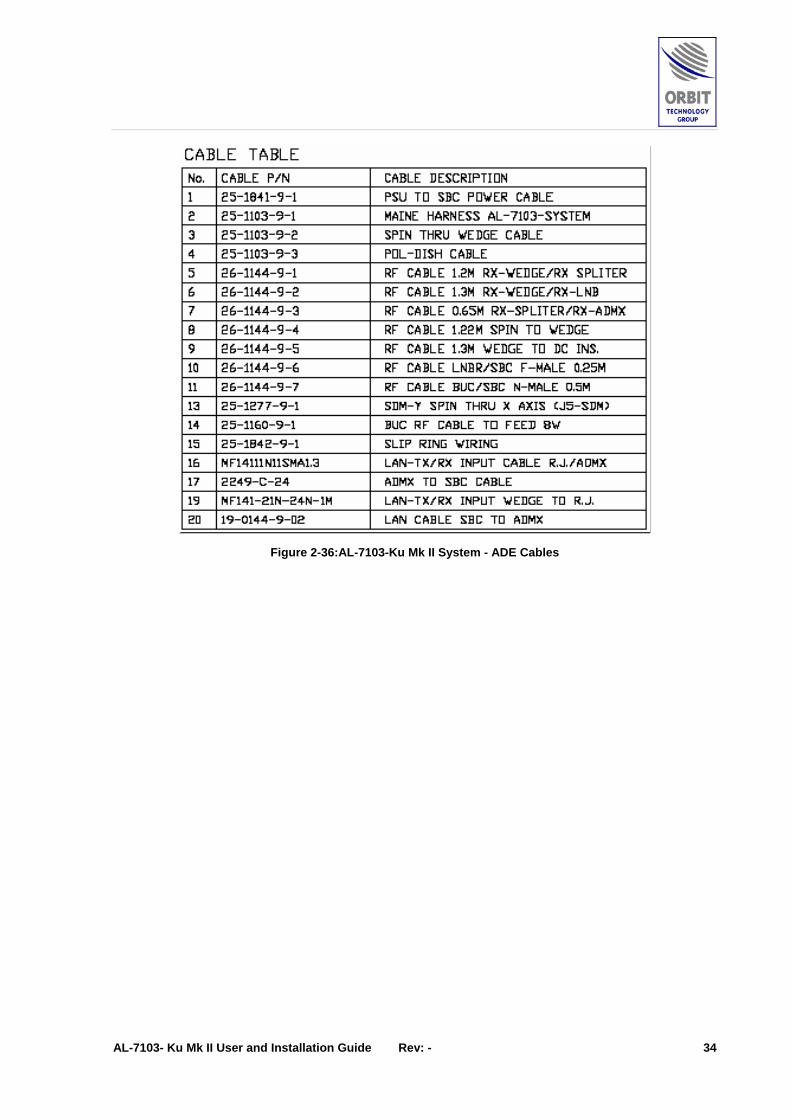
Figure 2-36: AL-7103-Ku Mk II System - ADE Cables

AL-7103- Ku Mk II User and Installation Guide Rev: - 35
2.4 System Technical Specifications
2.4.1 Weight ♦ 595lb (270Kg)
2.4.2 Packaging ♦ Weight: 450Kg
♦ Dimensions: L: 190 cm; W: 170 cm; H: 195cm
2.4.3 Radome ♦ Dome Diameter: 1.28m (50”)
♦ Base Diameter: 1.415m (55.7”)
♦ Radome Height: 1.610m (63.4”)
2.4.4 CCU Interfaces ♦ Modem Lock (IRD) Yes
♦ VGA Out: Yes
♦ LAN: Yes
♦ USB (for SW update): Yes
♦ Ship Gyro Interface NEMA 0183
Synchro
Step-by-Step
2.4.5 CCU Power Requirements 115VAC/220VAC 50Hz/60Hz (Switch), 150W
2.4.6 Antenna System ♦ Antenna Type: Gregorian Dual offset
♦ Antenna diameter: 45” (1.15m)
2.4.7 Frequency Operation ♦ Tx: 13.75-14.5 GHz
♦ Rx: 10.95-12.75 GHz
♦ Antenna Polarity: Linear H/V
2.4.8 Gain ♦ Tx: 42.5dBi @14.25 GHz
♦ Rx: 41dBi @11.70 GHz
♦ Cross-Pol. Discrimination: 35dB

AL-7103- Ku Mk II User and Installation Guide Rev: - 36
♦ System G/T 19 [dB/Kº], @ 11.7 GHz, 20º el.
♦ Sidelobe levels 29-25log(θ) dBi for 1.25 o <θ<7 o
+8 dBi for 7 o <θ<9.2 o
32-25log (θ) dBi for 9.2 o <θ<48 o
-10 dBi for 48 o <θ<180 o
♦ Radome Loss: 0.3dB Typical
2.4.9 LNBs ♦ 1 of 3 Bands, available on request
♦ Frequency 10.95-11.70 GHz, 11.70-12.2GHz,
12.25-12.75GHz.
♦ N/F: 0.7 dB
♦ LO Stability: ±10 KHz
♦ GPS Built-In
♦ Satellite Narrow-Band Tracking Receiver (NBR): Built-In
♦ Radio Package: 4W or 8W BUC
2.4.10 Range of Motion ♦ Full hemispherical coverage, down to satellite elevation view angle as
low as 0° at all sea conditions.
♦ With no mechanical “points of singularity” (No “Keyholes” at Zenith & Horizon).
♦ Azimuth: Continuous
♦ Elevation: 0º to 90º
(view angle including ship motion))
♦ Polarization: V/H
♦ Pointing Accuracy: 0.1° RMS.
2.4.11 Ship Motion ♦ Roll: ±30° @ 8 sec.
♦ Pitch: ±15°@ 6 sec.
♦ Yaw: ±8° @ 15 sec.
♦ Turning Rate: 12°/sec
2.4.12 Electrical Interfaces
Power Requirements: ♦ AC (ADE) AUTO RANGE, 90 to 250 VAC,
50/60 Hz, 350W, (with 4W BUC)

AL-7103- Ku Mk II User and Installation Guide Rev: - 37
L-band: ♦ RX: 950 – 1950 MHz
♦ TX: 950 – 1450 MHz (STD)
950 – 1700 MHz (EXT)
GPS out: ♦ Update rate: 1 per second
♦ Availability: Continuously
NBR Bandwidth: ♦ 0 – 70KHz (50KHz)
Or
♦ 70 – 180KHz (150KHz)
Or
♦ 180 –400KHz (300KHz)
♦ Beacon Signal (for the NBR): Min. C/N 10dB per relevant B/W
2.4.13 Environmental Conditions for Above Deck Equipment (ADE) ♦ EMI/RFI: EN 6132:97:A3:03 &
ETSI EN 320 340 Sec. 4.2.1
♦ Shock: MIL-STD 810E Method 516.5 Pro. I
♦ Vibration: MIL-STD-167-1 (Mast Mounted)
♦ Temperature: -20°C to +60°C
♦ Humidity: Up to 100% @ 40°C
♦ Wind Speed: 100 Knots

AL-7103- Ku Mk II User and Installation Guide Rev: - 38
3 Principles of Operation
3.1 Acquisition and Tracking Algorithm Maintaining a constant look angle towards the satellite is achieved by combination of following the feedback of the IMU (“Stabilization”) and periodically slight off-bore-site movement of the antenna so as to peak it to the point of maximal reception (“Step-track”).
Stabilization and Step-tracking of the antenna so as to maintain constant view angle towards the satellite is considered in this manual as “Tracking”.
The AL-7103-Ku Mk II system is designed to acquire and track a pre-selected satellite. For the system, the satellite is an entity defined by the following three parameters:
♦ Satellite location on the Geo-stationary arch: positive for East and negative for West longitudes, for example: -4.0 for Amos 4.0 deg West.
♦ Tracking (“Hunt”) frequency, given in L-Band MHz, for example 1200.0 MHz
♦ Rx Polarization selection: Vertical (“Pol-A”) or Horizontal (“Pol-B”)
On the reception of the Acquisition command, the AL-7103-Ku Mk II system will engage in a series of automatic actions designed to acquire and track the pre-selected satellite defined by the above three parameters, as depicted in the following diagram:

AL-7103- Ku Mk II User and Installation Guide Rev: - 39
Figure 3-37: AL-7103-Ku Mk II System – Simplified Acquisition and Tracking Algorithm

AL-7103- Ku Mk II User and Installation Guide Rev: - 40
3.2 Modes of Operation In principal, after proper installation, set-up and alignment, the AL-7103-Ku Mk II system will function in a completely automatic manner, i.e., after power-up the system will automatically acquire and track the last selected satellite without any intervention from an external operator.
The AL-7103-Ku Mk II system utilizes a number of lower level modes of operation, all to achieve this: Satellite Acquisition, Tracking, Validation, Searching and Re-acquisition
The advanced AL-7103-Ku Mk II system Man-machine interface (CCU screen and keyboard) allows activation of each and every of the lower-level modes, independently. Moreover – quite a number of modes are introduced to allow system installation, set-up, alignment and check-out. Among those are:
♦ Satellite Manual Pointing and Maintenance
♦ Mechanical Axes Manual Pointing and Maintenance
♦ Graphical Logger screen
♦ Spectrum Analyzer screen
♦ BUC Monitoring screen.
The utilization of some of the most frequently used functions is described in the Frequently Used Functions (FUF) manual.
3.3 Tracking Receiver Feedback A good quality signal strength indication is needed for the Step-track part of antenna tracking. “Good quality” is considered an indication having as much of Signal to Noise ratio as possible.
The tracking signal coming from the satellite may be one of the following:
♦ Satellite Beacon: normally un-modulated CW
♦ Customer Data Channel: normally occupying few hundred KHz to few MHz of bandwidth, with digital modulation (QPSK or BPSK)
♦ Unique tracking channel, put up by the customer especially for tracking
♦ Wide-band TV transponder, digital or analog.
The AL-7103-Ku Mk II system set-up may be adjusted to accommodate each of the above using either the Wide-band or Narrow-band tracking receiver selection.
To achieve optimal performance, following selections are recommended:
♦ Satellite Beacon: Narrow-band receiver with 50KHz filter
♦ Customer Data Channel: Narrow-band receiver with either 50, 150 or 300 KHz filter as per the Data Channel occupied bandwidth

AL-7103- Ku Mk II User and Installation Guide Rev: - 41
♦ Special tracking channel – Normally this is a 16 Kbps or 32 Kbps QPSK modulated signal: Narrow-band receiver with 50 KHz filter
♦ Wide-band (TV) transponder, digital – Wide-band receiver or Narrow-band receiver
♦ Wide-band TV transponder, analog – Wide-band receiver.
Another important aspect to be considered is the fact that the selected tracking is unique to the selected satellite and does not exist, or at least is received on a considerable lower level, from adjacent satellites.
If this is not the case, the AL-7103-Ku Mk II system might lock onto an adjacent satellite.
In general, the priority for selection of tracking signal from this perspective will be as follows:
♦ Special tracking channel – uniquely defined within the group of adjacent satellites
♦ Satellite beacon –uniquely defined for the same type of satellites, still must make sure that two adjacent satellites do not have the same beacon!
♦ Customer Data Channel
♦ Wide band (TV) transponder, digital or analog.
3.4 Satellite Validation
3.4.1 Introduction During tracking, a situation may develop where the antenna will lock onto an incorrect target, such as:
♦ Adjacent satellite producing signals in the same exact frequency range as the AL-7103 tracking feedback
♦ Terrestrial source of electromagnetic interference in the above mentioned spectrum range
♦ Strong reflections from obstructing structures, producing wide-band noise, covering the relevant part of the spectrum.
The AL-7103-Ku Mk II system tracking may be set-up to periodically check if it is locked on the right satellite.
This is possible only if additional information regarding the satellite validity may be obtained.
Two options may be utilized:
♦ Satellite Modem Lock indication (“IRD Lock”)
♦ Narrow Band Receiver Lock indication (“NBR Lock”).
3.4.2 IRD Lock The AL-7103-Ku Mk II system is able (per appropriate set-up) to periodically check the status of a Go/No-go indication coming from the modem, signaling that the modem has (and is) successfully locked on the data stream received from the satellite.

AL-7103- Ku Mk II User and Installation Guide Rev: - 42
Taking into account that the data stream is defined by quite a few parameters (such as Frequency, Modulation, Data-rate, Coding, Rate of Forward Error Correction) one can see that the chance for an exact same signal to be present on another satellite will be quite low.
This fact turns it into a powerful tool to make sure that the antenna is indeed not locked on some noise and is tracking the right satellite.
3.4.3 NBR Lock Since the antenna is relatively small, (approx. 3.5 deg beam-width), an L-Band NBR (Narrow Band Receiver) circuit may be required, in order to avoid “Lock” on adjacent satellites while engaging the Step-Track algorithm.
The AL-7103-Ku Mk II system is able (per appropriate set-up) to periodically check the status of a Go/No-go indication produced by the internal Narrow-Band Receiver (NBR), contained within the SBC.
The Narrow band receiver will give a “Lock” status if for the following situation:
♦ Receiver Bandwidth is set to “50KHz” and the signal is CW-70KHz range having at least 7 dB S/N
♦ Receiver Bandwidth is set to “150KHz” and the signal is 70-200KHz range having at least 7 dB S/N
♦ Receiver Bandwidth is set to “300KHz” and the signal is 200-400 KHz range having at least 7 dB S/N.
The primary function of this is to validate that the AL-7103-Ku Mk II system is not locking onto noise or clutter after temporary blockage, obstruction, interference or clutter.
L-Band Power Detector The NBR L-Band Power Detector, depicted in the following Figure, is a part of the antenna positioning control loop of the satellite communication system. It receives the full satellite 1st IF band of 920-2150 MHz and eventually filters out a specific narrow band PILOT signal of a specific satellite. The Pilot signal is received by a dual-conversion scheme and all surrounding signals filtered out by a switched narrow band BPF bank (50 KHz, 100 KHz, 300 KHz), to be detected by a very precise power detectors scheme with 0.1 dB changes in pilot power detection capability.

AL-7103- Ku Mk II User and Installation Guide Rev: - 43
Figure 3-38: NBR L-Band Detector

AL-7103- Ku Mk II User and Installation Guide Rev: - 44
4 Getting Started - Basic System Operation
4.1 System Start-Up
To Power Up the System:
• Turn the ADE and the CCU’s POWER switch ON.
Operating system messages are displayed, and then the Banner/Self-Test screen appears for a period of 10 seconds, during which a 10-to-0 countdown is displayed.
The system can be operated from Basic Operation screen or Operation screen, which provides additional operating capabilities. Under normal conditions the ship’s operator will use the Basic Operation screen. To enter Basic Operation screen, wait for the 10-to-0 countdown to end.
• If you need to enter the Operation screen, press <C> key during the 10-to-0 countdown, or <O> in the Basic Operation screen.
The ENTER PASSWORD window is displayed. Type your password and press ENTER.
The power-up sequence is fully automatic, provided that the system is configured to Auto-Start (default setting). At the end of power-up, the system is locked on the satellite that was last selected and saved prior to system shutdown.

AL-7103- Ku Mk II User and Installation Guide Rev: - 45
4.2 Basic Operation Screen The Basic Operation screen is the main system screen for the operator, which provides basic needed operation capabilities.
Figure 4-4 illustrates Operation screen main sections.
Figure 4-39:Basic Operation Screen
Selecting the Do option from the menu bar will open the operation menu that allows basic functions to be activated. These operations will be explained later in this manual.
Menu Bar Antenna
Deviation Field System Status
Field
AGC Field
Satellite and Channel select Field
System Messages Field
Antenna Position Field
Ship Coordinates Field

AL-7103- Ku Mk II User and Installation Guide Rev: - 46
4.3 Selecting a Satellite and Channel When power-up is completed, the system is automatically locked onto the satellite that was last selected and saved prior to system shutdown.
To select a different Satellite:
1. Type <1> for the DO MENU bar (or click on DO), Type <S> for SATELLITE (or click SATELLITE).
The SATELLITE window appears.
2. Click on the desired satellite, and select it by pressing ENTER or
clicking OK.
The SATELLITE window appears, listing the available selected-satellite tracking control channels. Disregard this window-by pressing enter.
To select the optimal tracking frequency use the Spectrum Analyzer Screen (SAS) as described below.
Remember that the receiver incorporated in the AL-7103 SBC is a Wide-band receiver, and looking on signals narrower then a few MHz of bandwidth may be not feasible

AL-7103- Ku Mk II User and Installation Guide Rev: - 47
When selecting the tracking frequency also take notice that it may be resident also on the adjacent satellite. If such a frequency is selected, the antenna will wonder off to the other satellite. In that case – return the antenna back to it nominal satellite view angle by the “Point-to-Sat” command and use the SAS to pick another frequency.
3. Spectrum Analyzer Screen (SAS) for Viewing Wide-Band Satellite Spectrum
The Spectrum Analyzer screen will only work with Wide-band tracking receiver selected.
To access, from “Operation Screen” or “Maintenance Screen” press “R”
To configure the Spectrum Analyzer measurement, press “C”:

AL-7103- Ku Mk II User and Installation Guide Rev: - 48
Start and Stop frequency values may be used to set up a full or partial range of measurement.
For Ku-Band full range is: 920 to 2150 MHz
For C-Band full range is: 950 to 1450 MHz
Frequency Step may be set up to as fine as 0.125 MHz, but one mast take into consideration that the measurement time will rise proportionally.
A scan of full Ku-Band range in 1MHz steps without averaging (Averaging set to 1) takes about 3-4 seconds
To make a measurement, one must first make sure that the system is not in “Step-track”. The reason for this is that “Step-track” is using the Tracking receiver resource. If the system is currently in “Step-track” – turn it to “Peak”.
To run the Spectrum Analyzer measurement press “R”.
To Store a recorded Pattern, press “W” then select a filename and save.
Below find some examples of Satellite Spectrum recordings taken by AL-7103 Ku and C, as viewed from Orbit roof in Natanya:
Satellite: Amos 4.0 West, Horizontal Pol, Ku-Band, LNB LO 10.0 GHz,

AL-7103- Ku Mk II User and Installation Guide Rev: - 49
Satellite: Amos 4.0 West, Vertical Pol, Ku-Band, LNB LO 10.0 GHz,
Satellite: Arabsat 26.0 East, C-Band, Linear Pol Satellite as seen with Circular Pol antenna

AL-7103- Ku Mk II User and Installation Guide Rev: - 50
4. Using SAS to Select Optimal Tracking Frequency for Wide-Band Receiver
Once a Satellite Spectrum is presented on the Spectrum Analyzer Screen (see paragraph above), a vertical dotted line marks the highest-level frequency:
Satellite: NSS6 95.0 East, Vertical Pol, Ku-Band, LNB LO 10.0 GHz,
This frequency is also stated as “Peak Freq” at the top of the screen: 1598.000 MHz.
If the “LoadRcv” function is activated, this frequency will be loaded into the tracking receiver:

AL-7103- Ku Mk II User and Installation Guide Rev: - 51
Press Enter to OK, then check by exiting the Spectrum Analyzer screen and viewing the “Receiver” sub-window in Maintenance Screen. Selected “Freq” will be: 1598.000 MHz
5. Using SAS for Satellite Identification
Spectrum Analyzer Screen may also be used to help identify a satellite. This may be done by comparing a measured pattern with a stored reference pattern.
First measure the current satellite pattern:
Press “G” to recall previously saved pattern and add it to the same graph:

AL-7103- Ku Mk II User and Installation Guide Rev: - 52
In the given example it is pretty obvious that the measured satellite is indeed the same satellite which pattern was saved as a reference.
If the two curves are not so obviously similar, one may use the “Correlation” number, which is calculated and presented on the upper right corner. In the case above the Correlation is 0.99 out of 1.00.
Usually Correlation of over 0.8 means positive satellite identification.

AL-7103- Ku Mk II User and Installation Guide Rev: - 53
4.4 Moving the Antenna using Manual Mode The following procedure is used for maintenance and testing purposes, or for finding the satellite when the system does not acquire it automatically.
To move the Antenna in Manual Mode:
1. From the menu bar, select DO MENU and click MANUAL.
The CONFIRM YOUR CHOICE window appears.
2. To confirm, press ENTER or click OK.
MANUAL MODE window appears at the bottom left corner of the OPERATION screen.
3. To move the antenna to any direction, use the up/down arrow
keys or the mouse to highlight the pertaining axis bottom-field, and use the right/left arrows or the mouse to increase/decrease the angle in step increments.
For each axis (Azimuth, Elevation and PolSkew).
The MANUAL MODE window provides two display fields: the upper field displays the current angle of the axis, and the bottom one displays the new manually changed angle.

AL-7103- Ku Mk II User and Installation Guide Rev: - 54
4.5 Restarting the System If the system did not complete the Auto Start sequence, or you want to initialize the system, use the following steps:
To restart the system:
1. From the menu bar, select DO MENU and click RESTART.
The CONFIRM YOUR CHOICE window appears.
2. To confirm your command, press ENTER or click OK.
• The system will initialize the Pedestal X, Y and Z encoders and initialize the IMU for 6 minutes.
• While the Restart is in progress you can not operate the system, a message will appear on the System Messages window: ‘Auto Restart in Progress’, The IMU will countdown for 6 minutes. After the IMU countdown will finish, the system will lock on the last saved satellite.

AL-7103- Ku Mk II User and Installation Guide Rev: - 55
4.6 Manual Setting of Heading Manual setting of heading is needed if:
• Ship’s compass is either inactive or not yet connected (ex: in midst of system installation)
To Set the Heading:
1. From the menu bar, select DO MENU and click SETCOMPASS.
The SHIP HEADING window appears.
2. To confirm, press ENTER or click OK.
The system will update the Ships Heading.
• For incremental compass types (Step-by-Step, Synchro 36:1, Synchro 360:1), a start value of the compass may be set.
• For absolute type, (NMEA-0183, Synchro 1:1), a default compass value may be set. This value will prevail until a valid compass update is received.
• When entering a Compass value, it might affect the accuracy of the IMU X Y Z sensors. It is then recommended to run the System Restart process again.

AL-7103- Ku Mk II User and Installation Guide Rev: - 56
4.7 Activating Step-Track Mode The Step-Track mode is automatically activated under normal working conditions. However, if you need to manually activate it for maintenance and testing purposes, perform the following steps.
• Make sure you are on the correct satellite with the correct tracking channel.
• Make sure the AGC level is above the noise floor (-80 dBm).
• Make sure the AGC is above the Threshold. If the AGC is below the Threshold the system will go automatic to Search mode after 60 second of Step track.
To activate the Step-Track Mode:
1. From the menu bar, select DO MENU and click STEP TRACK.
The CONFIRM YOUR CHOICE window appears.
2. To confirm, press ENTER or click OK.
The system will switch to STEP TRACK mode.

AL-7103- Ku Mk II User and Installation Guide Rev: - 57
4.8 Stow the System To Stow the system:
1. From the menu bar, select DO MENU and click STOW.
The STOW window appears.
2. To confirm, press ENTER or click OK.
The system will switch to STOW mode.
The Stow mode is used to move the system into a certain position, to allow an easy accessibility for maintenance on the ADE.

AL-7103- Ku Mk II User and Installation Guide Rev: - 58
4.9 Manual Setting of GPS Lat/Long Location
If for some reason there are no GPS position updates, or the GPS is Malfunctioning/Disconnected you can enter the ship’s position manually.
To enter the GPS position manually:
1. From the menu bar, select DO MENU and click SETGPS.
The CONFIRM YOUR CHOICE window appears.
2. To confirm, press ENTER or click OK.
The GPS position will update.
The Latitude and Longitude angles are entered in their decimal form, meaning that +32.5125 degree Latitude are actually 32 deg 30 minutes 45 seconds of arch North to Equator, while –128.7523 degrees Longitude are actually 128 degrees 45 minutes and 8 seconds of arch West of Greenwich.
To make those calculations you must remember that 1 degree of arch is divided into 60 minutes, while each minute of arch in turn contains 60 seconds, so that each degree of arch actually contains 3600 seconds.
32.5125 degrees of Latitude are 32 degrees and 0.5125*3600 = 1845 seconds.
1845 seconds are 1845/60 = 30 minutes and 0.75 * 60 = 45 seconds. The fact that 32.5125 Latitude is a positive number means that it’s given North of the Equator. 32.5125 degrees of Latitude are therefore 32 degrees 30 minutes and 45 seconds North of Equator.
Similarly it may be shown that –128.7523 degrees translate to 128 degrees 45 minutes and 8 seconds of arch. The fact that it is a negative number means that it is given West of the Greenwich line.
AL-7103- Ku Mk II User and Installation Guide Rev: - 59
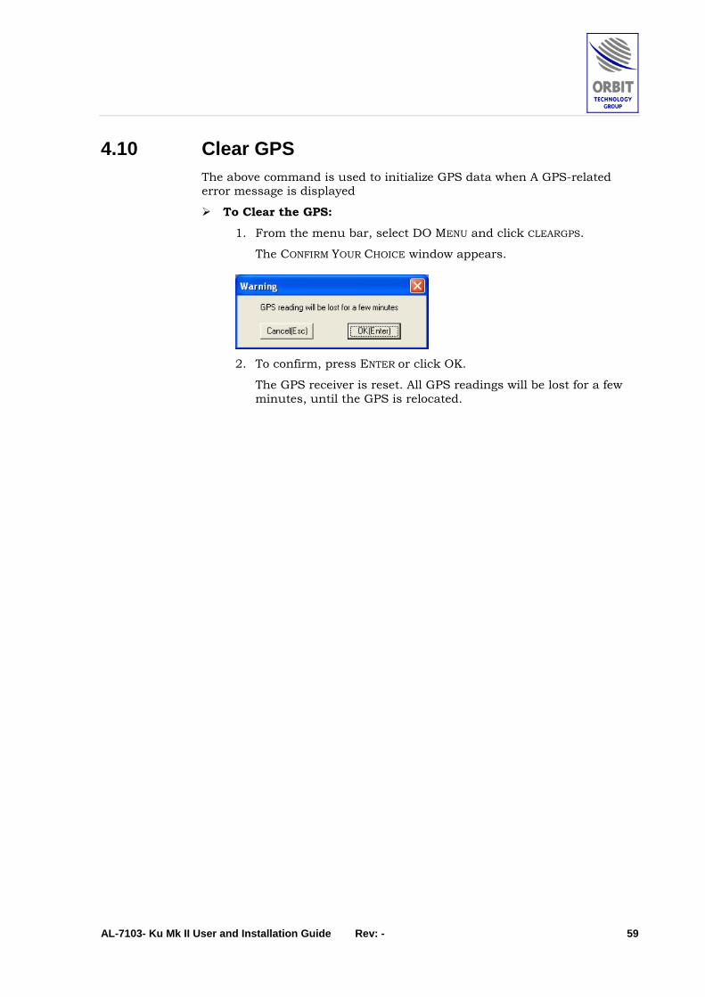
4.10 Clear GPS The above command is used to initialize GPS data when A GPS-related error message is displayed
To Clear the GPS:
1. From the menu bar, select DO MENU and click CLEARGPS.
The CONFIRM YOUR CHOICE window appears.
2. To confirm, press ENTER or click OK.
The GPS receiver is reset. All GPS readings will be lost for a few minutes, until the GPS is relocated.

AL-7103- Ku Mk II User and Installation Guide Rev: - 60
4.11 Setting AGC Threshold To set the AGC Threshold:
1. From the menu bar, select DO MENU and click SET THRESHOLD.
The SET THRESHOLD LEVEL window appears.
2. Type in a new value (in dbm) into the window, and to confirm,
press ENTER or click OK.
The THRESHOLD LEVEL is updated.
The THRESHOLD LEVEL should be approx 5 dB below the maximum AGC level

AL-7103- Ku Mk II User and Installation Guide Rev: - 61
4.12 Viewing Software Version Details To view the software version details:
From the menu bar, select DO MENU and click SHOW VERSION.
The VERSION window appears, listing version numbers and dates of the PROGRAM and COMMUNICATION software modules.
For proper CCU- Controller (SBC) communication, the Program and Communication versions installed on both units should be the same, respectively.

AL-7103- Ku Mk II User and Installation Guide Rev: - 62
4.13 Using Host Menu To use the Host menu:
Type <H> or from the menu bar, click HOST.
The HOST sub-menu appears.
1. To use the COMMUNICATION functions, click the COMMUNICATION.
The HOST COMMUNICATION screen appears.

AL-7103- Ku Mk II User and Installation Guide Rev: - 63
• In order to update the SBC IP address, click on the TCP/IP tab and update.
• The SBC IP address by default is always: 192.9.200.10.
2. To use the SATELLITE DATABASE functions, click the SATELLITES DATABASE option.
The SATELLITES DATABASE sub-menu appears.
The Satellite data base is loading automatically from the controller (SBC) when the communication between the CCU and SBC is initiated.

AL-7103- Ku Mk II User and Installation Guide Rev: - 64
4.14 Replacing the LNB To replace the LNB:
1. On the CCU, select the STOW mode.
2. Open the radome hatch.
3. Disconnect the coaxial cable from the LNB connector.
4. Remove four screws securing the LNB to the filter.
5. Unpack the new LNB.
6. Install the 0-ring gasket on the LNB.
7. Place the LNB on the filter and fasten four screws securing it.
8. Connect the coaxial cable to the LNB connector.
Figure 4-40: Ku-Band LNB Replacement
AL-7103- Ku Mk II User and Installation Guide Rev: - 65
5 Error Messages & Troubleshooting
5.1 Error Messages In case of a malfunction, the CCU displays a Message, Warning or an Error, depending on the malfunction classification.
The messages are classified into three categories, each identified by a different color:
♦ Message - green (e.g. System Shut-Down, Pedestal Y Axis Jammed)
♦ Warning – blue (e.g. Compass Communication Failed)
♦ Error –red (e.g. Pedestal X Axis Encoder Fault).
The following Table lists all the messages.
Table 5-1. CCU Messages
Message Possible Cause
Error Messages
“Error: SDU/IMU Power out of tolerance” IMU +5VDC, or the Servo Drive power indications exceeded the predefined tolerance limits
“Error: Restart timed out” The system was not able to complete the restart routine in the predefined time (normally set to 10 minutes)
“Error: Pedestal X Axis Jammed” No movement is recorded from Pedestal X-axis encoder, while the controller produces a steering command
“Error: Pedestal Y Axis Jammed” No movement is recorded from Pedestal Y-axis encoder, while the controller produces a steering command
“Error: No Maintenance Configuration File”
The SBC couldn’t find the Maintenance Configuration file in its Flash memory (disk C:\), on power-up.
“Error: No Operational Configuration File”
The SBC couldn’t find the Operational modes Configuration file in its Flash memory (disk C:\), on power-up.
“Error: No Satellite Database File” The SBC couldn’t find the Satellite Database file in its Flash memory (disk C:\), on power-up.
“Error: No System Configuration File” The SBC couldn’t find the System Parameters Configuration file in its Flash memory (disk C:\), on power-up.
“Error: No Valid IMU Calibration File” The SBC couldn’t find the IMU Calibration file in its Flash memory (disk C:\), on power-up.

AL-7103- Ku Mk II User and Installation Guide Rev: - 66
Table 5-1. CCU Messages
Message Possible Cause
“Error: Satellite File Read Error” The SBC couldn’t read the Satellite database file from its Flash memory (disk C:\), during operation.
“Pedestal X NE2 Encoder Fault” The BiSS digital communication protocol with axis-X NE2 encoder has more then 10% failure rate.
“Pedestal Y NE2 Encoder Fault” The BiSS digital communication protocol with axis-Y NE2 encoder has more then 10% failure rate.
“Pedestal Z NE2 Encoder Fault” The BiSS digital communication protocol with axis-Z NE2 encoder has more then 10% failure rate.
“Pedestal X NE2 Enc Init Fault” The axis-X NE2 encoder initialization has failed.
“Pedestal Y NE2 Enc Init Fault” The axis-Y NE2 encoder initialization has failed.
“Pedestal Z NE2 Enc Init Fault” The axis-Z NE2 encoder initialization has failed.
“Error: Pedestal Z Axis Jammed” No movement is recorded from Pedestal Z-axis encoder, while the controller produces a steering command
“Error: SBC Pwr/Tmpr out of tolerance” One of the SBC power indications (+5v,+/-12v,+2.5v etc.) exceeded the predefined tolerance limits. This error will also appear if the SBC internal temperature exceeded its tolerance limits.
“Error: SDM-X Servo Power Loss” The SDM-X Power is down or it is disconnected.
“Error: SDM-Y Servo Power Loss” The SDM-Y Power is down or it is disconnected.
“Error: SDM-Z Servo Power Loss” The SDM-Z Power is down or it is disconnected.
“Error: SDM-X Stepper Driver Fault” The SDM-X Stepper Driver Fault indicator is on (red). Relevant only with IM805 Stepper drivers
“Error: SDM-Y Stepper Driver Fault” The SDM-Y Stepper Driver Fault indicator is on (red). Relevant only with IM805 Stepper drivers
“Error: SDM-Z Stepper Driver Fault” The SDM-Z Stepper Driver Fault indicator is on (red). Relevant only with IM805 Stepper drivers

AL-7103- Ku Mk II User and Installation Guide Rev: - 67
Table 5-1. CCU Messages
Message Possible Cause
“Error: I/O Bus Fault” Starting with SBC software Ver4.22 in conjunction with Altera version 0xCDXX, the SBC can recognize a fault in I/O PC Bus by writing to Altera and reading the value back. If the value is not the same – an appropriate message is produced.
Warning Messages
“Warning: LNB Power Over-Current” The controller 13/18VDC power supply, feeding the LNB is overloaded
“Warning: Compass Communication Failed”
No valid communication frames were received on the NMEA-0183 compass Com port for over 1.5 seconds.
“Warning: GPS Communication Failed” No valid communication frames were received on the GPS Com port for over 5 seconds.
“Warning: No GPS Position Updates” No GPS position-fix frames were received on the GPS Com port for over 30 seconds.
“Warning: System not initialized” The AL-7103 didn’t undergo the process of initialization which includes all axes Encoder init as well as IMU init.
“Warning: LNB voltage out of tolerance” The controller 13/18VDC power supply, feeding the LNB, is exceeding its predefined tolerance levels
“Warning: Antenna view blocked” The Antenna has moved into one of the predefined blockage areas
“Warning: No communications with host” The communications with the host computer, identified by a predefined IP address, has timed-out (10 seconds).
“Warning: Signal below threshold” The controller signal strength indication (AGC) on the selected frequency is lower then the predefined threshold level.
“Warning: IMU-ACU Communication Fault”
The communications between IMU and the controller has timed-out.
“Warning: Receiver Cal Table not Found” The SBC couldn’t find the internal wide-band receiver linearization calibration file in its Flash memory (disk C:\), on power-up.
“Warning: BUC L-Band Cal Table not Found”
The SBC couldn’t find the ADMx (BUC Input) analogue detector linearization calibration file in its Flash memory (disk C:\), on power-up. This Warning will be issued only if the BUC L-Band Power indicator is enabled.

AL-7103- Ku Mk II User and Installation Guide Rev: - 68
Table 5-1. CCU Messages
Message Possible Cause
“Warning: BUC L-Band Cal Table not Found”
The SBC couldn’t find the BUC output analogue detector linearization calibration file in its Flash memory (disk C:\), on power-up. This Warning will be issued only if the BUC Rf-Power indicator is enabled.
“Warning: PolSwitch not connected” The SBC recognized a situation in which both Forward and Reverse limit sensors of the PolSwitch are ON. This is interpreted as a not connected PolSwitch.
“Warning: BUC L-Band Cal Table not Found”
The SBC couldn’t find the BUC analogue detector linearization calibration file in its Flash memory (disk C:\), on power-up. This Warning will be issued only if the BUC L-Band Power indicator is enabled.
“Warning: X-Axis Forward Limit” The position encoder readout of the X-axis exceeded its Forward Limit configuration definition.
“Warning: X-Axis Reverse Limit” The position encoder readout of the X-axis exceeded its Reverse Limit configuration definition.
“Warning: Y-Axis Forward Limit” The position encoder readout of the Y-axis exceeded its Forward Limit configuration definition.
“Warning: Y-Axis Reverse Limit” The position encoder readout of the Y-axis exceeded its Reverse Limit configuration definition.
“Warning: iNBR Interface not recognized” iNBR warning.
“Warning: iNBR High LO Unlocked” iNBR warning.
“Warning: iNBR Low LO Unlocked” iNBR warning.
“Warning: Tracking Error Exceeds Limit” Tracking Error Exceeds Limit.
“Warning: Octans-IMU: Alignment in process”
N/A for this system.
“Warning: Octans-IMU: Anomaly” N/A for this system.
“Warning: Octans-IMU: Data not ready” N/A for this system.
Messages (Information)
“Auto-Restart in progress” System is going thru initialization stage including – IMU init, Encoder init and optionally, Satellite acquisition
“Acquiring a Satellite” System is currently acquiring a satellite
“System no initialized” Encoder and IMU were not yet initialized.
“System Shutdown” System was shut down

AL-7103- Ku Mk II User and Installation Guide Rev: - 69
Table 5-1. CCU Messages
Message Possible Cause
“System Shutdown, Ped-X Jammed” System was shut down due to “Pedestal-X Jammed” fault (No. 36)
“System Shutdown, Ped-Y Jammed” System was shut down due to “Pedestal-Y Jammed” fault (No. 37)
“PolSkew Disabled, Polarizer Jammed” System was shut down due to the fact that no movement was recorded from Pedestal Z-axis encoder, while the controller produced a steering command
“System Shutdown, Ped-X Encoder” System was shut down due to “Pedestal-X Encoder Fault” (No. 8), or “Pedestal-X NE2 Encoder Fault” (No. 104), or “Pedestal-X NE2 Enc Init Fault” (No. 111)
“System Shutdown, Ped-Y Encoder” System was shut down due to “Pedestal-Y Encoder Fault” (No. 9), or “Pedestal-Y NE2 Encoder Fault” (No. 105) or “Pedestal-Y NE2 Enc Init Fault” (No. 112)
“System Shutdown, Power Loss” System was shut down due to “SDU/IMU power lout of tolerance” (No. 15)
“System Shutdown, Restart Time” System was shut down due to “Restart time-out” (No. 17)
“IRD Validation in process” IRD is being re-validated during Step-track operation. Note that this message is presented for a very short time and is barely visible on the controller screen.
“System Shutdown, Ped-Z Jammed” System was shut down due to “Pedestal-Z Jammed” fault (No. 119)
“System Shutdown, SBC Power/Tempr” System was shut down due to “SBC Pwr/Tmpr lout of tolerance” (No. 121)
“System Shutdown, Ped-Z Encoder” System was shut down due to “Pedestal-Z NE2 Encoder Fault” (No. 106) or “Pedestal-Z NE2 Enc Init Fault” (No. 113)
“System Shutdown, SDM-X Power” System was shut down due to “SDM-X Servo Power Loss” fault (No. 126)
“System Shutdown, SDM-Y Power” System was shut down due to “SDM-Y Servo Power Loss” fault (No. 127)
“System Shutdown, SDM-Z Power” System was shut down due to “SDM-Z Servo Power Loss” fault (No. 128)
“System Shutdown, SDM-X Drv Flt” System was shut down due to “SDM-X Stepper Driver Fault” fault (No. 129)
“System Shutdown, SDM-Y Drv Flt” System was shut down due to “SDM-Y Stepper Driver Fault” fault (No. 130)
“System Shutdown, SDM-Z Drv Flt” System was shut down due to “SDM-Z Stepper Driver Fault” fault (No. 131)

AL-7103- Ku Mk II User and Installation Guide Rev: - 70
Table 5-1. CCU Messages
Message Possible Cause
“System Halted, Axes Jammed” System has experienced multiple jammed-axis faults. More than 6 occurred in two minutes – the system is therefore halted.
“Ax-X Ne2 Enc Reg Read Failed” While initialization of Axis-X Ne2 encoder, one of the registers was not read correctly (CRC check failed). If not accompanied by other Warning or Error, this is just FYI, as the register is automatically re-read.
“Ax-Y Ne2 Enc Reg Read Failed” While initialization of Axis-Y Ne2 encoder, one of the registers was not read correctly (CRC check failed). If not accompanied by other Warning or Error, this is just FYI, as the register is automatically re-read.
“Ax-Z Ne2 Enc Reg Read Failed” While initialization of Axis-Z Ne2 encoder, one of the registers was not read correctly (CRC check failed). If not accompanied by other Warning or Error, this is just FYI, as the register is automatically re-read.
“Ax-X Ne2 Enc Reg Write Failed” While initialization of Axis-X Ne2 encoder, writing to one of its registers write failed (read-back failed). If not accompanied by other Warning or Error, this is just FYI, as the register is automatically re-written.
“Ax-Y Ne2 Enc Reg Write Failed” While initialization of Axis-Y Ne2 encoder, writing to one of its registers write failed (read-back failed). If not accompanied by other Warning or Error, this is just FYI, as the register is automatically re-written.
“Ax-Z Ne2 Enc Reg Write Failed” While initialization of Axis-Z Ne2 encoder, writing to one of its registers write failed (read-back failed). If not accompanied by other Warning or Error, this is just FYI, as the register is automatically re-written.
“iNBR Validation in process” NBR is being re-validated during Step-track operation. Note that this message is presented for a very short time and is barely visible on the controller screen.

AL-7103- Ku Mk II User and Installation Guide Rev: - 71
5.2 Basic Troubleshooting If you experience persistent problems while acquiring a satellite, and
no error messages appear, check that all the system parameters are correctly set.
Check the parameters on the BASIC OPERATION screen in accordance with the following table:
Parameter Check Display Corrective Action
Pitch and Roll Verify that the readings displayed in the Ship Coordinates fields appear to be abnormal at the dockside (i.e., there is a pitch or roll of 2º and more).
Restart the system.
Latitude and Longitude
Check with Bridge to verify that the parameters displayed in the Ship Coordinates fields are correct.
Carry out a Clear GPS procedure, and check for updates in the Maintenance screen.
Compass heading
Check with Bridge to verify that the parameters displayed in the Ship Coordinates fields are correct.
Check that if necessary, the Compass Offset has been set.
For a step-by-step compass, use the Set Compass mode to enter initial values.
Otherwise, check that the Compass’ wiring is in order.
Visual inspection of antenna
Verify that the antenna appears to be actually pointing in the direction stated in the Antenna Position fields.
Restart the system.

AL-7103- Ku Mk II User and Installation Guide Rev: - 72
6 Concise Installation Guide
6.1 Preparing the Installation Site & Unpacking the System This section describes the site preparation and initial unpacking procedures.
6.1.1 Above-the-Deck Installation Considerations ♦ The location selected for installation should have maximum non-
blocked hemispheric view down to 10 degrees visibility.
♦ Consideration should be given to allow free-of-obstacles space below the support to allow sufficient maintenance access for technical staff.
♦ The mounting location should not be immediately adjacent to high-power radars or other communication equipment.
Correct planning will lead to a successful installation with minimum trouble before and throughout system operation.
6.1.2 Unpacking the System The System is packed in a single wooden crate.
The shipping crate’s contents may have shifted during transportation.
As soon as you open the crate, you must check for evidence of damage and immediately report it to the shipper and Orbit Marine.
For unpacking purposes, you will need access both from the front and back of the crate.
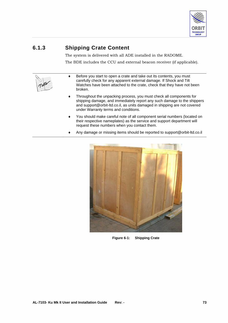
AL-7103- Ku Mk II User and Installation Guide Rev: - 73
6.1.3 Shipping Crate Content The system is delivered with all ADE installed in the RADOME.
The BDE includes the CCU and external beacon receiver (if applicable).
♦ Before you start to open a crate and take out its contents, you must carefully check for any apparent external damage. If Shock and Tilt Watches have been attached to the crate, check that they have not been broken.
♦ Throughout the unpacking process, you must check all components for shipping damage, and immediately report any such damage to the shippers and [email protected], as units damaged in shipping are not covered under Warranty terms and conditions.
♦ You should make careful note of all component serial numbers (located on their respective nameplates) as the service and support department will request these numbers when you contact them.
♦ Any damage or missing items should be reported to [email protected]
Figure 6-1: Shipping Crate

AL-7103- Ku Mk II User and Installation Guide Rev: - 74
6.1.4 Unpacking and Visual Inspection ♦ Place the shipment crate on a rigid, leveled surface.
♦ Open the crate without damaging the contents.
1 2 3 4
5 6 7
Figure 6-2: Opening the Shipping Crate
♦ Remove the Radome by releasing its ring clamp. When removing the radome-securing ring, pay attention not to scrape the radome.
Figure 6-3: Releasing the Securing Ring
♦ Unwrap the nylons that cover the system.
♦ Cut the marked cable ties that secure the system’s moving parts.

AL-7103- Ku Mk II User and Installation Guide Rev: - 75
Figure 6-4: Removing Cable Ties
♦ Visually inspect the exterior of the equipment for evidence of any physical damage that might have occurred in shipment/storage.
♦ Mark all the S/N of the system and its units (PSU, SBC, IMU, BUC, SDM’s, etc.).
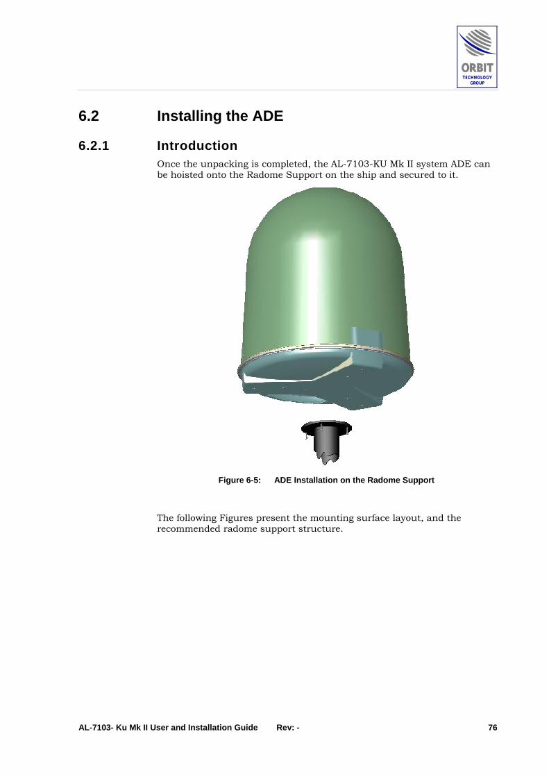
AL-7103- Ku Mk II User and Installation Guide Rev: - 76
6.2 Installing the ADE
6.2.1 Introduction Once the unpacking is completed, the AL-7103-KU Mk II system ADE can be hoisted onto the Radome Support on the ship and secured to it.
Figure 6-5: ADE Installation on the Radome Support
The following Figures present the mounting surface layout, and the recommended radome support structure.

AL-7103- Ku Mk II User and Installation Guide Rev: - 77
4X 1/2-13 UNC, 22MM DEPTH
DIA. 350MM
.EQ.SP
6X 1/2-13 UNC, 22MM DEPTH
13.780 9.213350MM 234MM
DIA. 13.78
Figure 6-6: Mounting Surface

AL-7103- Ku Mk II User and Installation Guide Rev: - 78
Figure 6-7: Radome Support – Recommended Structure

AL-7103- Ku Mk II User and Installation Guide Rev: - 79
6.2.2 Lifting and Mounting Procedure The aim of the following procedure is to provide the main steps that are required to securely lift the AL-7103 system ADE.
To lift the ADE, use the Sling Assembly depicted in the following Figure, or an equivalent one (for 2 Tons lifting weight).
Figure 6-8: Recommended Sling Assembly

AL-7103- Ku Mk II User and Installation Guide Rev: - 80
♦ Attach the master link with suitable lifting slings to the crane safety hook.
Safety Hook
Yellow Master
Lifting Slings
Figure 6-9: Master Link
♦ Attach the lifting slings to the Radome base three lifting arms.
Lifting Arms
Figure 6-10. Lifting Arms

AL-7103- Ku Mk II User and Installation Guide Rev: - 81
♦ Wrap the Dome with the red belt.
Figure 6-11. Red Belt
♦ Release the screws in seven points, three through the metal brackets and four through the two wooden strips
Metal Bracket
Wooden Strips Screws
Figure 6-12: Holding Screws
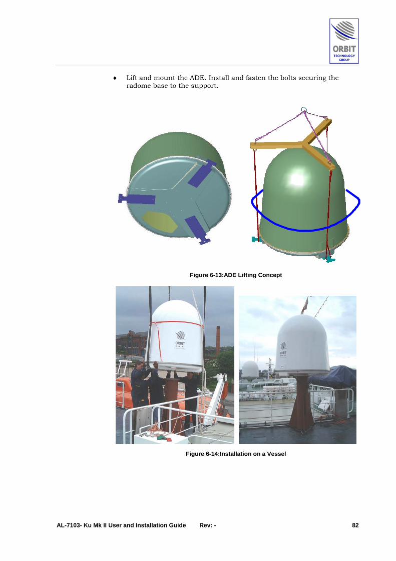
AL-7103- Ku Mk II User and Installation Guide Rev: - 82
♦ Lift and mount the ADE. Install and fasten the bolts securing the radome base to the support.
Figure 6-13:ADE Lifting Concept
Figure 6-14:Installation on a Vessel

AL-7103- Ku Mk II User and Installation Guide Rev: - 83
6.2.3 ADE Cables Connections
Introduction The following cables are to be connected to the ADE:
♦ Mains Power Supply cable
♦ BDE-ADE Link coaxial cable.
The above cables inserted go into the ADE via a pass-thru gland that is installed in an opening rilled in the radome base.
Figure 6-15: ADE Cables Connections
Preparing the Radome Pass-Thru Opening The preparation procedure includes the following steps:
1. Drilling a 40 mm hole in the Radome Base.
The AG-40 gland was selected to be large enough to allow pass-thru of the ADE-BDE coax cable with its N-type connector installed, and of the AC mains cable. Therefore, the ADE-BDE coax cable may be pre-terminated off the ship, prior to on-board installation.
2. Installing an AG-40 Gland, or equivalent.
3. Inserting the cables and tightening the gland.
It is very important to verify, after the gland is tightened, that it secures both cables and doesn't allow any cable movement inside the gland. If the cables are loose inside the gland (this may be depending on the type of cables and gland used), wrap 7-10cm length area of the cables running thru the gland using a Self-amalgamating Tape (Scapa PIB or equivalent).
4. Sealing the gland thread using RTV Sealing Compound.
Make sure that the gland is tightened over the cables. Note that due to the fact that there are two cables thru the gland, the opening is not completely sealed, even though the gland holds the cables tight. To seal the opening completely, apply RTV Sealing Compound.
Power Cable Connection
ADE-BDE Cable Connection
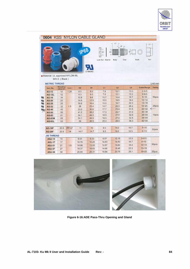
AL-7103- Ku Mk II User and Installation Guide Rev: - 84
Figure 6-16: ADE Pass-Thru Opening and Gland

AL-7103- Ku Mk II User and Installation Guide Rev: - 85
ADE Power Cable Connection To connect mains power supply to the ADE, perform the following:
The ADE is fed by AC power supplied by customer.
1. Remove the protective cover on the POWER IN side.
2. Connect the power cable wires, in the right polarity, to the POWER IN terminals.
3. Reinstall the protective cover.
(1) AC Input
(2)Utility
Outlets
(3) SystemPower Switch
Figure 6-17: ADE Power Connection

AL-7103- Ku Mk II User and Installation Guide Rev: - 86
ADE-BDE Cable Connection The ADE is connected to the BDE by a single LMR-400/600 coax cable. To connect the cable to the BDE, perform the following procedure:
1. Install an EZ-400-NMH Connector on the ADE-Side of the LMR-400/600 cable, as instructed in Appendix A.
2. Connect the cable connector to the ADE’s N-Type connector bracket, as shown in the following Figure.
Figure 6-18: ADE-BDE Cable Connection

AL-7103- Ku Mk II User and Installation Guide Rev: - 87
6.3 Installing the BDE
6.3.1 CCU and Modem Installation The BDE units (CCU and Modem) are typically installed on dedicated 19-inch racks, located in the ship’s equipment room(s).
Figure 6-19:Typical BDE Rack Installation
CCU
Customer’s Modem

AL-7103- Ku Mk II User and Installation Guide Rev: - 88
6.3.2 Connecting CCU Cables
CCU Rear-Panel Connectors Overview The following Figure shows the CCU rear-panel connectors, and the subsequent Table specifies the type and function of each connector.
Figure 6-20: AL-7103-KU Mk II CCU Rear Panel Connectors
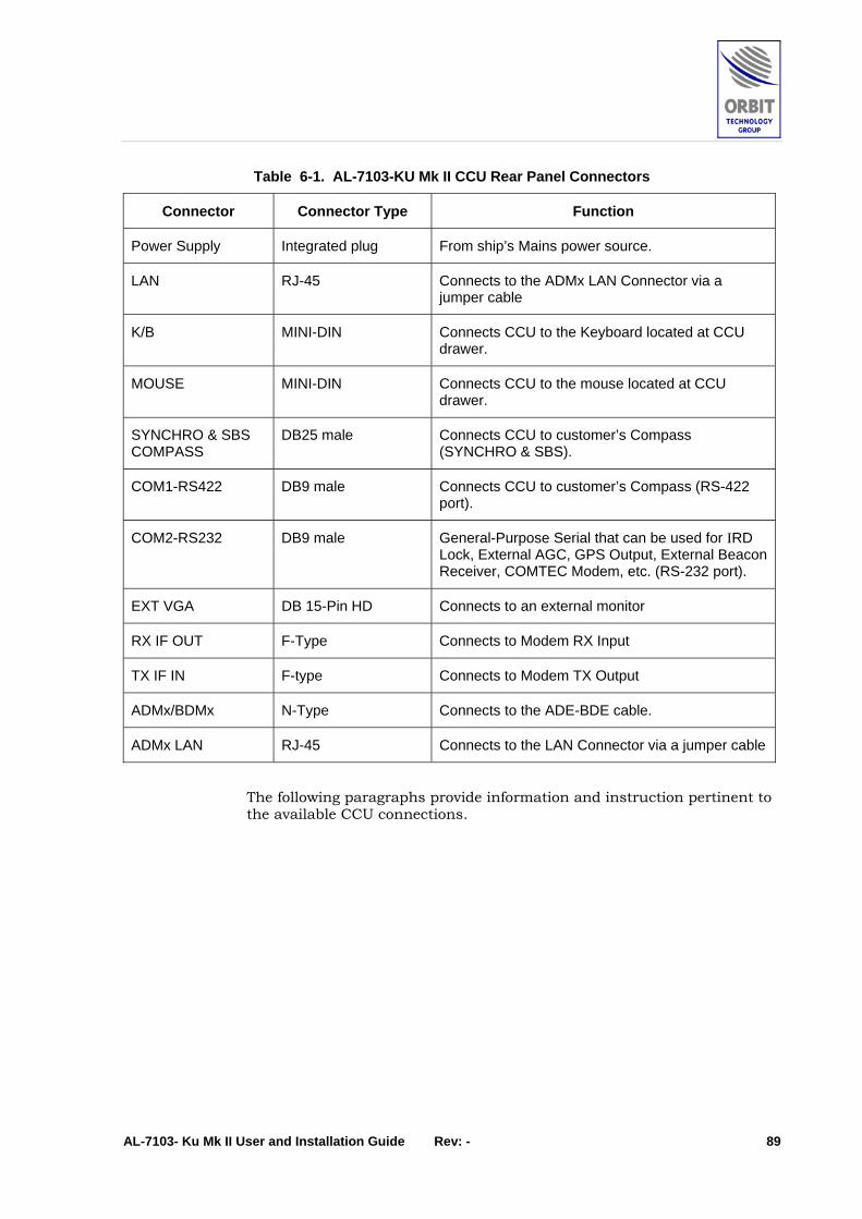
AL-7103- Ku Mk II User and Installation Guide Rev: - 89
Table 6-1. AL-7103-KU Mk II CCU Rear Panel Connectors
Connector Connector Type Function
Power Supply Integrated plug From ship’s Mains power source.
LAN RJ-45 Connects to the ADMx LAN Connector via a jumper cable
K/B MINI-DIN Connects CCU to the Keyboard located at CCU drawer.
MOUSE MINI-DIN Connects CCU to the mouse located at CCU drawer.
SYNCHRO & SBS COMPASS
DB25 male Connects CCU to customer’s Compass (SYNCHRO & SBS).
COM1-RS422 DB9 male Connects CCU to customer’s Compass (RS-422 port).
COM2-RS232 DB9 male General-Purpose Serial that can be used for IRD Lock, External AGC, GPS Output, External Beacon Receiver, COMTEC Modem, etc. (RS-232 port).
EXT VGA DB 15-Pin HD Connects to an external monitor
RX IF OUT F-Type Connects to Modem RX Input
TX IF IN F-type Connects to Modem TX Output
ADMx/BDMx N-Type Connects to the ADE-BDE cable.
ADMx LAN RJ-45 Connects to the LAN Connector via a jumper cable
The following paragraphs provide information and instruction pertinent to the available CCU connections.
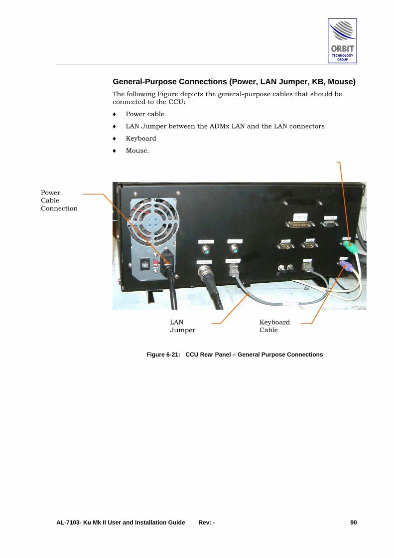
AL-7103- Ku Mk II User and Installation Guide Rev: - 90
General-Purpose Connections (Power, LAN Jumper, KB, Mouse) The following Figure depicts the general-purpose cables that should be connected to the CCU:
♦ Power cable
♦ LAN Jumper between the ADMx LAN and the LAN connectors
♦ Keyboard
♦ Mouse.
Figure 6-21: CCU Rear Panel – General Purpose Connections
Power Cable Connection
LAN Jumper
Keyboard Cable

AL-7103- Ku Mk II User and Installation Guide Rev: - 91
ADE-BDE Cable Connection The ADE is connected to the BDE by a single LMR-400/600 coax cable. To connect the cable to the CCU, perform the following procedure:
1. Install an EZ-400-NMH Connector on the BDE (CCU)-Side of the LMR-400/600 cable, as instructed in Appendix A.
2. Connect the cable connector to the CCU ADMx/BDMx connector, as shown in the following Figure.
Figure 6-22: CCU Rear Panel – ADMX/BDMX Connector
ADMx / BDMx Connector

AL-7103- Ku Mk II User and Installation Guide Rev: - 92
Serial Communication and Compass Connectors The CCU rear panel includes three communication connectors:
♦ Synchro and SBS Compass - Connects CCU to customer’s Compass (SYNCHRO & SBS)
♦ COM1 – RS-422 - Connects CCU to customer’s Compass (RS-422 port).
♦ COM2 – RS-232 - General-Purpose Serial port.
Figure 6-23: CCU Rear Panel – Serial and Compass Connectors
The following Table specifies the communication connector pin-out.
The subsequent paragraphs describe how to use each connector.
Synchro and SBS Compass
COM2 – RS-232 Connector
COM1 – RS-422 Connector

AL-7103- Ku Mk II User and Installation Guide Rev: - 93
Table 6-2. Communication Connectors Pin Out

AL-7103- Ku Mk II User and Installation Guide Rev: - 94
NMEA-0183 RS-422 Compass Connection General
The National Marine Electronics Association (NMEA) 0183 standard defines an electrical interface and data protocol for communications between marine instrumentation.
The NMEA-0183 standard is 4800 baud and consists of several different ASCII sentences.
Electrical Interface
This standard allows a single "talker” and several "listeners" on one circuit. The recommended interconnect wiring is a shielded twisted pair, with the shield grounded only at the talker. The standards do not specify the use of any particular connector. NMEA-0183 recommends that the talker output comply with EIA-422. This is a differential system, having two signal lines, A and B.
The voltages on the "A" line correspond to those on the older TTL single wire, while the "B" voltages are reversed (while "A" is at +5, "B" is at ground, and vice versa). In either case, the recommended receive circuit uses an opto-isolator with suitable protection circuitry. The input should be isolated from the receiver's ground. In practice, the single wire, or the EIA-422 "A" wire may be directly connected to a computer's RS-232 input.
The following Figure depicts how to connect an RS-422 NMEA-0183 Compass to the CCU’s COM1 Connector.
Connecting an RS-422 NMEA-0183 Compass to COM1 Connector:
CCU Connector Mating Connector Wiring Diagram
COM1-RS422
Mating Connector Pin Out
Pin Signal
2 RXD-
4 RXD+
5 GND
Figure 6-24: RS-422 NMEA-0183 Compass - Connection Scheme
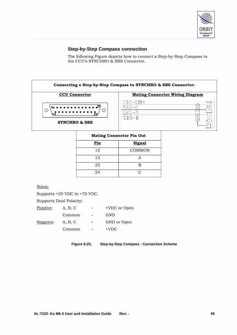
AL-7103- Ku Mk II User and Installation Guide Rev: - 95
Step-by-Step Compass connection The following Figure depicts how to connect a Step-by-Step Compass to the CCU’s SYNCHRO & SBS Connector.
Connecting a Step-by-Step Compass to SYNCHRO & SBS Connector:
CCU Connector Mating Connector Wiring Diagram
SYNCHRO & SBS
Mating Connector Pin Out
Pin Signal
12 COMMON
13 A
25 B
24 C
Notes:
Supports +20 VDC to +70 VDC.
Supports Dual Polarity:
Positive: A, B, C – +VDC or Open
Common – GND
Negative: A, B, C – GND or Open
Common – +VDC
Figure 6-25: Step-by-Step Compass - Connection Scheme

AL-7103- Ku Mk II User and Installation Guide Rev: - 96
Synchro Compass connection The following Figure depicts how to connect a Synchro Compass to the CCU’s SYNCHRO & SBS Connector.
Connecting a Synchro Compass to SYNCHRO & SBS Connector:
CCU Connector Mating Connector Wiring Diagram
SYNCHRO & SBS
Mating Connector Pin Out
Pin Signal
8 REF+
10 REF-
5 GND
18 S1
22 S2
23 S3
15 GND
Note:
Supports 115 VAC Reference. 60 VAC Reference is Optional.
Figure 6-26: Synchro Compass - Connection Scheme
To find and enter the system’s Offset to Ships Compass, refer to the FUF Manual, paragraphs: 17,20,21.

AL-7103- Ku Mk II User and Installation Guide Rev: - 97
IRD LOCK Connection The following Figure depicts how to connect IRD LOCK modem signal to the CCU’s COM2 Connector.
Connecting IRD LOCK to COM2 Connector:
CCU Connector Mating Connector Wiring Diagram
COM2-RS232
Mating Connector Pin Out
Pin Signal
7 12VDC OUTPUT
8 IRD INDICATOR
Note:
Connect Pin 7 & Pin 8 via “dry-contact” relay.
Figure 6-27: IRD LOCK - Connection Scheme

AL-7103- Ku Mk II User and Installation Guide Rev: - 98
External AGC Connection The following Figure depicts how to connect External AGC to the CCU’s COM2 Connector.
Connecting External AGC to COM2 Connector:
CCU Connector Mating Connector Wiring Diagram
COM2-RS232
Mating Connector Pin Out
Pin Signal
6 AGC IN
9 GND
Figure 6-28: External AGC - Connection Scheme

AL-7103- Ku Mk II User and Installation Guide Rev: - 99
RS-232 Channel Connection The following Figure depicts how to connect RS-232 Channel to the CCU’s COM2 Connector.
Connecting RS-232 Channel to COM2 Connector:
CCU Connector Mating Connector Wiring Diagram
COM2-RS232
Mating Connector Pin Out
Pin Signal
2 RXD
4 TXD
5 GND
Figure 6-29: RS-232 Channel - Connection Scheme

AL-7103- Ku Mk II User and Installation Guide Rev: - 100
6.4 Modem Integration (Rx & Tx Path Gain Calculation)
6.4.1 Introduction Following completion of the AL-7103 Mk II System installation, the Modem (which is not part or Orbit’s deliverables) should be installed, connected and configured.
When installing the modem, verify the following:
♦ Rx signal, into the Modem, is within the modem dynamic range.
♦ Tx signal, from the modem, is set so that the BUC is not saturated, and on the other end strong enough for quality transmission.(1dB Compression point).
The following paragraphs provide calculation examples, for a 50 m ADE-BDE cable, showing how to calculate the gain budget along the system’s Rx and Tx paths.
For any other cable type or cable length, perform the pertaining calculations.
6.4.2 Rx Chain Gain Budget (from LNB to Rx Modem Input)
# Parameter Value
1 Total Rx chain Gain (ADMx & BDMx) 25dB, typical
2 Typical loss of LMR-400 cable 9dB @ L-BAND for 50m
3 Typical loss of cables, splitter & rotary joint within the pedestal
8dB
4 Total loss (# 2+3) 17dB
5 Total Rx system Gain (# 1–4) 8dB
6 Typical LNB output – 55dBm
7 Rx Input level to the modem (# 6+5) -47dBm
Conclusion: The calculated Rx Input level to the modem (-47dBm) is typically within the dynamic range of the modems, (depends on types of modem, modulation schemes & data rates).

AL-7103- Ku Mk II User and Installation Guide Rev: - 101
6.4.3 Tx Chain Gain Budget (from the modem to the BUC input)
Coarse Adjustment
# Parameter Value
1 Total Tx chain Gain (ADMx & BDMx) 17dB, typical
2 Typical loss of LMR-400 cable 15dB @ 4.7GHz for 50m
3 Typical loss of cables, DC Inserter & rotary joint within the pedestal
6dB
4 Total loss (# 2+3) 21dB
5 Total Tx system Gain (# 1–4) -4 dB
6 Typical BUC input level for 1dB Compression
4W BUC: – 16dB
8W BUC: – 24dB
7 Typical coarse value of modem output, for BUC 1dB Compression (# 6-5)
4W BUC: – 12dB
8W BUC: – 20dB
8 Typical Modem dynamic output range 0 to – 30dB
Conclusion: The calculated coarse value of modem output, for BUC 1dB Compression is well within the typical Modem dynamic output range (0 to – 30dB).
Fine adjustment model output level (using the HUB station) Setting the Modem power for driving the BUC to 1dB Compression:
1. Activate “Tx on” in the Modem.
Caution: use the coarse typical calculated values as a starting modem power level (in order to avoid BUC saturation).
2. Raise the Modem power 1 dB at a time while monitoring of the signal at the HUB Spectrum Analyzer (1dB of power giving increase of 1dB of signal).
3. 1dB Compression is reached when 1dB increase of Modem power causes less then 0.5dB of increase in signal level. Do not increase the Modem power beyond this point, as it will drive the BUC into compression.
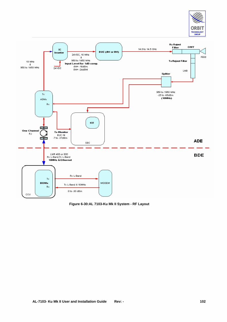
AL-7103- Ku Mk II User and Installation Guide Rev: - 102
Figure 6-30: AL 7103-Ku Mk II System - RF Layout

AL-7103- Ku Mk II User and Installation Guide Rev: - 103
7 Appendix A – Installation Addendum
7.1 Preparing the ADE-BDE Cable
7.1.1 EZ-400-NMH Connector Installation Procedure on LMR-400 The following Figures depict how to install the connectors on both sides of the LMR cable.

AL-7103- Ku Mk II User and Installation Guide Rev: - 104
Figure 7-1: EZ-400-NMH Connector Installation Procedure on LMR-400 (sheet 1 of 2)

AL-7103- Ku Mk II User and Installation Guide Rev: - 105
Figure 7-2: EZ-400-NMH Connector Installation Procedure on LMR-400 (sheet 2 of 2)

AL-7103- Ku Mk II User and Installation Guide Rev: - 106
Prep tool for LMR-400 crimp style connectors (Refer to step 2 & 3 in the Installation Procedure)
Part No.: ST-400EZ Stock No.: 3190-401.
Debarring tool (Refer to step 4 in the Installation Procedure). Part No.: DBT-01 Stock No.: 3190-406.
Crimp tool for LMR-400 (Refer to step 7 in the Installation Procedure)
Part No.: CT-400/300 Stock No.: 3190-666 -.
Or alternatively use:
Crimp Tool Part No.: HX-4 Stock No.: 3190-200
0.429" hex dies for EZ-400 crimp connectors
Part No.: Y1719 Stock No.: 3190-202
Figure 7-3: EZ-400-NMH Connector Installation Procedure on LMR-400 – Tools


![Orbit type: Sun Synchronous Orbit ] Orbit height: …...Orbit type: Sun Synchronous Orbit ] PSLV - C37 Orbit height: 505km Orbit inclination: 97.46 degree Orbit period: 94.72 min ISL](https://static.fdocuments.in/doc/165x107/5f781053e671b364921403bc/orbit-type-sun-synchronous-orbit-orbit-height-orbit-type-sun-synchronous.jpg)