Oracle IP Dome Camera - NetVu Ltd | Innovators in visual ... There are sensitive day/night camera...
52
Oracle IP Dome Camera Installation Manual www.dedicatedmicros.com
-
Upload
hoangkhuong -
Category
Documents
-
view
214 -
download
0
Transcript of Oracle IP Dome Camera - NetVu Ltd | Innovators in visual ... There are sensitive day/night camera...

Oracle IP Dome CameraInstallation Manual
www.dedicatedmicros.com

Dedicated Micros ©20102
Ora
cle
Whilst every attempt is made to ensure these manuals are accurate and current, Dedicated Micros reserve the right to alter or modify the specification of the machine described herein without prejudice.
ContentsIntroduction ................................................................3Components supplied - External ................................7Components supplied - Internal .................................7Electrical Connections - External ...............................8Electrical Connections - Internal ................................10Mounting Configurations - External ...........................11Mounting Configurations - Internal .............................14Dome Configuration ...................................................18Configuring the Unit ...................................................19System .......................................................................21Language ...................................................................22Time and Date ...........................................................23User Accounts ............................................................24Camera - Status .........................................................26Camera - Presets .......................................................27Camera - Patrols ........................................................28Camera - Privacy Masks ............................................29Camera - Camera Settings ........................................30Camera - Event Settings ............................................32Network ......................................................................33Video Trans ................................................................34Connections ...............................................................36Analytics ....................................................................37Viewer Defaults .........................................................38Go to Viewer ..............................................................40Connecting to the IP Oracle Dome ............................42Camera ......................................................................43IP Camera...................................................................... 44Camera Telemetry......................................................45IP Record ....................................................................... 46Using NetVu Observer ...............................................47Troubleshooting .........................................................48Appendix A .................................................................49

Dedicated Micros ©2010 3
Ora
cle
IntroductionThe Dedicated Micros IP Oracle PTZ dome is a precision unit, offering a wide variable speed range, together with ‘point&go’ and ‘Absolute Positioning’ capabilities. There are sensitive day/night camera versions with a switchable infra-red filter and with 36 times or 18 times optical zoom lenses plus 12 times digital enhancement suitable for outdoor use, or a colour/mono camera with 18 times optical zoom and 12 times digital enhancement suitable for indoor applications. The external Oracle dome is weatherproof (IP-66 rated).
The unit has a comprehensive set of features as standard, which can be tailored for individual preferences. These can be accessed through a local set of web page menus, or directly from the NetVu Connected server’s web pages.
Outline Specification: Speed range 0.05 to 300° / second max (both Pan and Tilt)Repeatability 5 minutes of arcControl NetVu Connected DV-IP protocolStorage capacity 99 preset positions 4 patrols of up to 32 preset positions 4 alarm inputs, 1 relay outputPower Supply 24VAC, Camera & control electronics:-18W indoor, 24W outdoorDimensions Outdoor variant: 206mm diameter x 240mm overall Indoor variant: 189mm diameter x 250mm overallProtection Outdoor variant - BS EN 60529 to level IP66 (no water ingress) Indoor variant - BS EN 60529 to level IP50 (no dust ingress)Weight Outdoor variant: 3.9kg + mounting bracket Indoor variant: 2.2kg + mounting bracketMounting Configurations Ceiling mount, pendant mount, wall bracket, corner mount, snowdrop
parapet & tile mounts availableServer Compatability SD Advanced, DV-IP Server, DV-IP HD, DV-IP RT, HighVu Excel
18X zoom day/night camera moduleSensor ¼” Ex-view HAD progressive scan CCDOptical range 4.1mm to 73.8mm zoom; F1.4 to F3.0 Auto-focus with manual override Privacy zones 24 programmable zones (8 on screen at any time)Video sensitivity 0.07 lux color 50IRE 0.01 lux ICR-on mode 50IREVideo resolution 440000 pixels PAL, 380000 NTSC 530 TVLVideo output NetVu Connected
36X zoom day/night camera moduleSensor ¼” Ex-view HAD progressive scan CCDOptical range 3.4mm to 122.4mm zoom; F1.6 to F4.5Auto-focus with manual override 24 programmable zones (8 on screen at any time)Video sensitivity 0.1 lux color 50IRE 0.01 lux color ICR-on 50IREVideo resolution 440000 pixels PAL, 380000 NTSC 530 TVLVideo output NetVu Connected
18X zoom colour/mono cameraSensor ¼” Super HAD CCDOptical range 4.1mm to 73.8mm zoom; F1.4 to F3.0Auto-focus with manual override Privacy zones 24 programmable zones (8 on screen at any time)Video sensitivity 1 lux color 50IREVideo resolution 440000 pixels PAL, 380000 NTSC More than 460 TVL PAL, 470 TVL NTSCVideo output NetVu Connected

Dedicated Micros ©20104
Ora
cle
Point&go provides the user with easy to use, fast, accurate telemetry control via an attached monitor. With no need for a telemetry keyboard, users are able to use Pan & Tilt control of a Dedicated Micros Oracle Dome simply by clicking an area of the monitor. The camera will instantly respond, positioning the selected area in the middle of the screen, ideal for tracking movement through a scene.
ePTZDedicated Micros ePTZ uses an advanced image ‘interpolation’ algorithm that reveals detailed information that simple pixel-stretching digital zoom commands cannot. Users can operate ePTZ as they would Analogue Zoom - moving around the scene and zooming in/out using the IR Remote Control or a supported Keyboard - even on static analogue cameras. Electronic Zoom can be carried out on both live and playback video. Providing the ability to retrospectively control and view an image, a great aid in post-event analysis.
Absolute PositioningUsing Camera Selection Maps and the unique Absolute Positioning capability of Dedicated Micros Oracle Dome cameras, an operator can, with one mouse click, select a camera and send it to view an area of the site (Pan and tilt). Absolute Positioning is ideal for following someone from camera to camera around a site and greatly increases event response time, particularly for operators unfamiliar with a site layout and camera location.
RF Interference warningThis is a class A product. In a domestic environment this product may cause radio frequency interference, in which case the user may be required to take adequate measures.
Product Safety
WARNING
• Installation and servicing is only to be carried out by suitably qualified and experienced personnel and should conform to all local codes.
• Only power low voltage cameras from the provided power supply. Use only a Class 2 power supply with a maximum current of 1.5 amps and the wiring as specified in the National Electrical Code ANSI/NFPA 70.
This camera range is designed for use in general purpose CCTV applications and has no other purpose.
Only operate your camera between the temperatures of -10°C and +40°C. This low voltage camera must be powered with either a 12V DC or a 24V AC power supply. Do not operate your camera outside its specified power supply range.

Dedicated Micros ©2010 5
Ora
cle
FCC CLASS B REGULATORY NOTICEThis device complies with part 15 of the FCC Rules. Operation is subject to the following two conditions: (1) This device may not cause harmful interference, and (2) this device must accept any interference received, including interference that may cause undesired This equipment has been tested and found to comply with the limits for a Class B digital device, pursuant to part 15 of the FCC Rules. These limits are designed to provide reasonable protection against harmful interference in a residential installation. This equipment generates uses and can radiate radio frequency energy and, if not installed and used in accordance with the instructions, may cause harmful interference to radio communications. However, there is no guarantee that interference will not occur in a particular installation. If this equipment does cause harmful interference to radio or television reception, which can be determined by turning the equipment off and on, the user is encouraged to try to correct the interference by one or more of the following measures:
Reorient or relocate the receiving antenna.
Increase the separation between the equipment and receiver.
Connect the equipment into an outlet on a different circuit different to the receiver.
Consult the dealer or an experienced radio/TV technician for help.
Modifications not expressly approved by the manufacturer could void the user’s authority to operate the equipment under FCC rules.

Dedicated Micros ©20106
Ora
cle
Camera CareIn order to avoid damaging your camera, note the following points:
CAUTION
• Remove all packaging inserts and the protective film from the dome cover before using the camera.
• This installation should be made by a qualified service person and should conform to all local codes.
CE NOTICE (EUROPEAN UNION).Marking by the symbol CE indicates compliance of this DM product to the Electromagnetic Compatibility Directive 89/336/EEC, and the Low Voltage Directive 73/23/EEC of the European Union. Such marking is indicative that this system meets the following technical standards.
• EN 61000-6-3 EMC Standard Residential, Commercial and Light Industry.• EN 61000-3-3 Limitations of voltage changes, fluctuations and flicker in public low-
voltage supply systems for equipment with rated current up to 16A.• EN 61000-3-2 Limits for harmonic current emissions for equipment with rated
current up to 16A.• EN 50130-4 Immunity requirements for components of fire, intruder and social
alarm systems.• EN 60950 Safety of IT and related equipment.• EN 55022 Class B. Radiated Emissions Standard, suitable for Commercial or
Residential use.• EN 60825-1 Safety standard for LED’s and Lasers.
Further details about these applicable standards can be obtained from Dedicated Micros Ltd. 1200 Daresbury Park, Daresbury, Cheshire, WA44HS.
A “Declaration of Conformity” with all relevant European Union Directives has been made, is on file and is available from the Dedicated Micros address above.
This product is marked with the CE symbol and indicates compliance with all applicable directives.
Directive 89/336/EEC.
A “Declaration of Conformity” is held at Dedicated Micros Ltd., 1200 Daresbury Park, Daresbury, Cheshire, WA44HS.

Dedicated Micros ©2010 7
Ora
cle
Components supplied - ExternalBefore installing the dome, please remove the components from the packaging and verify that all items listed below have been supplied:
1 x Dedicated Micros Oracle Dome enclosure and camera (with incorporated safety bond)
1 x Oracle Dome Power Supply (except USA)
1 x Dedicated Micros Oracle Dome manual
1 x 3M pre-wired cable
1 x 5mm A/F Hex wrench
Note for US Customers: The PSU must be a UL2044 approved Class 2 current limited 24VAC Power Supply with a maximum current of 1.5 amps and the wiring as specified in the National Electrical Code ANSI/NFPA 70.
Note: Mounting brackets may have been ordered and delivered separately.Important: The Advanced Programming and Control features on the Oracle IP Dome are only
available when used with the latest Dedicated micros DVRs. These include SD Advanced, DV-IP Server, DV-IP HD, DV-IP RT and HighVu Excel. Standard functionality will still be available with other control equipment.
Components supplied - InternalBefore installing the dome, please remove the components from the packaging and verify that all items listed below have been supplied:
1 x Dedicated Micros Oracle Dome enclosure and camera (with incorporated safety bond)
1 x Dedicated Micros Oracle Dome manual
1 x 5mm A/F Hex wrench
Note: The PSU must be a UL2044 approved Class 2 current limited 24VAC Power Supply with a minimum current of 1.5 amps and the wiring as specified in the National Electrical Code ANSI/NFPA 70. Dedicated Micros recommends the DM/94012 for indoor dome.
Note: Mounting brackets may have been ordered and delivered separately.Important: The Advanced Programming and Control features on the Oracle Dome are only
available when used with the latest Dedicated micros DVRs. These include SD Advanced, DV-IP Server, DV-IP HD, DV-IP RT and HighVu Excel. Standard functionality will still be available with other control equipment.

Dedicated Micros ©20108
Ora
cle
Electrical Connections - ExternalMultiway Connector
The dome receives power and data, and sends video and data via the multiway connector. This feeds into the PCB housed in the terminal box, which provides wiring breakout and inter-connectivity.
Note: The terminal box is not supplied in the USA.
Dome connector
C
V
D
R
E
U
K
J
H
B P A N M L
F S G T
Note: Viewed from wiring side
The 15 core cable connections are as follows:Cable Function Connector PinGreen/Yellow Earth F
Green/Yellow Earth G
White/Red Ethernet Rx+ C
Black/Red Ethernet Rx- P
Yellow Ethernet Tx- E
Green Ethernet Tx+ T
Brown 24VAC D
Blue 24VAC U
Violet Alarm 1 H
Pink Alarm 2 S
Grey Alarm 3 J
Orange Alarm 4 R
Black Alarm Ground K
White Relay A N
Red Relay B L

Dedicated Micros ©2010 9
Ora
cle
PCB
Alm
1
Alm
Gnd
Alm
2
Alm
Gnd
Alm
3
Alm
Gnd
Alm
4
Alm
Gnd
Rela
y A
Rela
y B
Vid
In +
Vid
In -
Tx/R
x +
A
Tx/R
x -
B
PW
R +
Pw
r -
Alm
1
Alm
2
Alm
3
Alm
4
Alm
Gnd
Rela
y A
Rela
y B
Shie
ld G
nd
Shie
ld G
nd
24V
AC
+
24V
AC
-
J1
J2
+ U
TP
- U
TP
Tx/R
x +
A
Tx/R
x -
B
Optional
Alarm/Relay
InputsTo Dome
Multiway
Connector
Cat5
Ethernet
Power
TEL
TERM
Minimum configuration The simplest connection possible to the Oracle Dome would require the following;
The Mains supply (live, earth and neutral) is connected to the heavy duty connector block mounted in the Power Supply Unit next to the PCB. Power select links (J1 & J2) should be set to 24VAC (centre and arrowed pin bridged as shown above). Telemetry termination (TEL TERM) link is not required (as shown above).
Function Colour PCB ConnectorSafety (Earth) Green/Yellow Shield Gnd
Drain Wire Bare Wire Shield Gnd
Power Brown PWR+
Power Blue PWR-
Ethernet Rx- White/Red Vid In+
Ethernet Rx+ Black/Red Vid In-
Ethernet Tx- Yellow Tx/Rx +A
Ethernet Tx+ Green Tx/Rx -B
Note: Whilst the Alarm and Relay inputs are not essential for minimum configuration, it is recommended that they are connected to the PCB in case they are required in the future.
Note: The Multiway cable should be securely clamped to the chassis using the screw clamp provided. The insulation should be stripped back to allow the clamp to contact the cable foil sheath. All glands into the PSU should be securely tightened to prevent the ingress of moisture.
Connecting the DVR to the Oracle Dome (via PCB)Video to the DVR is sent over Ethernet using NetVu Connected technology.

Dedicated Micros ©201010
Ora
cle
Electrical Connections - InternalThe dome requires connection to the power supply and to any required alarm connector on the DVR. The serial port connection is not required. There is no prepared cable included, the connector for the camera is included.
NC
NC
NC
NC
24VAC
24VAC
Ethernet
Pin 1 - Alarm 1Pin 2 - Alarm 2Pin 3 - Alarm 3Pin 4 - Alarm 4Pin 5 - Alarm GroundPin 6 - NCPin 7 - Relay APin 8 - Relay B
24V PowerSupply
+ -
The two RJ45 connectors are used for alarms and Ethernet.
RJ45 connectorsPin Connection1 Alarm 12 Alarm 23 Alarm 34 Alarm 45 Alarm Ground6 Not connected7 Relay A8 Relay BNote: The relay is suitable for switching DC only and is rated at 12Vdc 0.5A.
Multiway connectorThe serial and video connections are not required when using the IP Dome.
Connector Function24VAC 24VAC+ from UL2044 approved Class 2 current limited 24VAC 1A24VAC 24VAC- from UL2044 approved Class 2 current limited 24VAC 1A485A Not Connected485B Not ConnectedVid GND Not ConnectedVid Sig Not ConnectedNote: Refer to ‘Dome Configuration’ for a list of appropriate DVRs.

Dedicated Micros ©2010 11
Ora
cle
Mounting Configurations - ExternalWith appropriate brackets this dome enclosure can be mounted in any of the orientations shown below.
Note: Mounting brackets may have been ordered and delivered separately.
1
4
5
3
2
1. Wall/Pendant Mount (order code DM/90002) giving pendant or wall mount options.2. Extended Wall Mount (order code DM/90009) for more flexibility in wall mounting. 3. Corner Bracket (order code DM/90007) for mounting to corners of buildings in
conjunction with DM/90002. 4. Snowdrop mount bracket (order code DM/90004) for mounting at the top of a pole
or column.5. Pendant Mount (order code DM/90003 - 250mm; order code DM/90012 - 500mm;
order code DM/90013 - 1000mm; order code DM/90014 - 1500mm) for roof or parapet mounting.

Dedicated Micros ©201012
Ora
cle
Safety BondThe safety bond is designed to prevent damage to the dome if it should fall during installation or maintenance. It must be connected between the done mounting point and a suitable position, either on the bracket or within the ceiling void. Note that this point will receive the full force of the dome should it fall.
For wall, pendant & snowdrop mounted domes;1. Clip safety bond to the mounting bracket eyelet on flange of bracket to secure.
For standard ceiling mounted domes attach the supplied safety bond;1. Attach bond to a suitable secure position in the ceiling void.
Note: Always support dome with bond prior to mating connector. The weight of dome should be supported by bond ensuring no stress is placed on centre connector at any time.

Dedicated Micros ©2010 13
Ora
cle
Dome Mounting
A. Secure & hang dome to bracket by attaching safety bond spring clip to eyelet.Note: Procedure is the same for all installations.Note: Ceiling installation is made easier by removing an adjacent ceiling tile during installation.
B. Lift dome to bracket flange ensuring head of screws (previously fitted cap head screw) pass through keyhole slots. Twist to locate.
C. Mate the previously prepared central connector, refer to ‘Electrical Connections’ for more information, supplying power & control to dome (ensure power is off when connecting).
D. Tighten 4 top mounting fixings with Hexagonal key supplied to secure.E. Secure any plastic covers or trim (wall/pendant installations only).

Dedicated Micros ©201014
Ora
cle
Mounting Configurations - InternalWith appropriate brackets this dome enclosure can be mounted in any of the orientations shown below.
Note: Mounting brackets may have been ordered and delivered separately.
1
4
3
2
1. Wall/Pendant Mount (order code DM/90002) giving pendant or wall mount options.2. Corner Bracket (order code DM/90007) for mounting to corners of buildings in
conjunction with DM/90002. 3. Tile mount (order code DM/CSD/TMR) for suspended ceilings.4. Snowdrop mount bracket (order code DM/90004) for mounting at the top of a pole
or column.

Dedicated Micros ©2010 15
Ora
cle
Safety BondThe safety bond is designed to prevent damage to the dome if it should fall during installation or maintenance. It must be connected between the done mounting point and a suitable position, either on the bracket or within the ceiling void. Note that this point will receive the full force of the dome should it fall.
For wall, pendant & snowdrop mounted domes;1. Clip safety bond to the mounting bracket eyelet on flange of bracket to secure.
For standard ceiling mounted domes attach the supplied safety bond;1. Attach bond to a suitable secure position in the ceiling void.
Note: Always support dome with bond prior to mating connector. The weight of dome should be supported by bond ensuring no stress is placed on centre connector at any time.

Dedicated Micros ©201016
Ora
cle
Dome MountingPendant Mount
A. Secure and hang dome to bracket by attaching safety bond spring clip to eyelet.B. Lift dome to bracket flange ensuring head of screws (previously fitted Cap head
Screw) pass through keyhole slots. Twist to locate.C. Mate the previously prepared central connector, refer to ‘Electrical Connections’
for more information, supplying power & control to dome (ensure power is off when connecting).
D. Tighten 4 top mounting fixings with Hexagonal key (supplied) to secure.E. Secure any plastic covers or trim (wall/pendant installations only).

Dedicated Micros ©2010 17
Ora
cle
Tile Mount
Ø190mm
3 x Ø6mm
204mm PCD
A
C
E
F
D
B
A. Remove the selected tile that will have the dome mounted in it. Use the mounting ring (B) as a template to mark the drilling positions of the 3 x supporting holes on a 204mm pitch circle diameter (6mmØ holes, if using the supplied cavity plugs (A)) and the 190mmØ hole for the dome. Fit the cavity plugs (A) to the holes.
Note: The installer is responsible for ensuring the fixings used to mount the dome are suitable for the material and will adequately support the weight of the dome.
B. Attach the mounting ring to the dome using the provided 6 x M3x8 fixings (C).C. Re-install the tile in the ceiling. Secure and hang dome to a suitable mounting point
in the ceiling void by attaching safety bond spring clip to eyelet through the large centre hole in the tile.
Note: Ceiling installation is made easier by removing an adjacent ceiling tile during installation.
D. Fasten the dome to the mounting ring (B) using the provided 3 x No.8x1”(25.4mm) self tapping screws (D) (or suitable fixings provided by the installer).
E. Snap fit the provided tile mount bezel (E). This replaces the standard bezel (F) provided with the camera. Discard the standard bezel (F).

Dedicated Micros ©201018
Ora
cle
Dome ConfigurationThe Dome can be configured via the attached DVR. The special software features are available via the interface on DVR’s capable of accessing them (SD Advanced, DV-IP Server, DV-IP RT, DV-IP HD and HighVu Excel), refer to the documentation for your individual DVR for further details.
The Dome has advanced features that include Point and Go, Privacy masking, Presets, Sectors and Patrols. along with Camera and Event settings. Not all of these will be available on all DVR’s.
List of DVR’s required to utilise advanced programming features• SD Advanced, DV-IP Server, DV-IP HD, DV-IP RT and HighVu Excel running Gen3 pages.

Dedicated Micros ©2010 19
Ora
cle
Configuring the UnitLocating the Unit IP address
The unit is configured using on-board webpages. This can be done remotely once the unit has been installed in its chosen location.
The IP address of the unit is required to access these pages. When the dome is connected to a DHCP network for the first time, its IP address is unlikely to be known without referring to the settings of the network switch or router it is connected to.
The easiest way to open the webpages for the first time and identify the assigned IP address (via the Status page) is by connecting to the Dome using its DNS address.
The default DNS address for each dome is factory set to be its serial number. Therefore the address can be found from the serial label on the unit or via the packaging the dome came in,
The DNS address can be typed directly into the address bar of a web browser.
Note: If subsequently the dome is assigned a fixed IP address, its DNS address can no longer be used
Note: The dome’s DNS address can be changed subsequently to something more memorable or meaningful than its serial number by editing the System name option in the System configuration page.
If a permanent IP address is not assigned to the unit, it will attempt to contact the DHCP server every time it starts up, and periodically thereafter. If there is no DHCP server to allocate an IP address to the unit, the camera will use a default IP address (169.254.5.0 - 169.254.5.255) depending on the configuration of the blue and yellow address switches in the dome (default 169.254.5.1).
Note: Details on how to configure an Oracle IP Dome on a network without DHCP are available in Appendix A

Dedicated Micros ©201020
Ora
cle
Accessing the Configuration Web PagesThe unit is configured using the on-board web pages. To access these:
1. Launch a web browser, preferably on a PC on the same subnet as the unit.6.12
2. Type the IP address of the unit into the address bar.3. If prompted, enter a username and password. The default settings are;
username:dm and password:web.4. The Main Menu page will be displayed.
6.13
The configuration menus are accessible via the link on the left hand side of the page.

Dedicated Micros ©2010 21
Ora
cle
SystemThis menu shows the general information about the unit including the version of software installed, the unit’s serial number and the allocated IP address.
Product Descriptor Details the product model. Serial Number Identifies the serial number of the specific unit.PCB Serial Number Displays the PCB (Printed Circuit Board) serial number of the unit.System Name This field can be edited to allocate a name to the unit. This is
displayed when the unit is accessed via NetVu ObserVer and is sent when transmitting information to a Remote Video Response Centres (RVRC). The default value is the MAC address prefixed by ‘DM’.
MAC Address This is the MAC address assigned to the unit.IP Address This is the IP address allocated to the unit.Sub Net This is the subnet of the network where the unit is located. Gateway This is the IP address of the default gateway (router) assigned by
the DHCP server.Software Revision This identifies the version of software the unit is running.ANPR Library This identifies the version of software the unit is running.Webpage Library This identifies the version of web server the unit is running.Webpage Revision This identifies the webpage version the unit is running.Boot Software Rev. Displays the infrastructure componentry software revision.Applet Version This identifies the Java version used.

Dedicated Micros ©201022
Ora
cle
LanguageThis menu allows the system language to be set. Changing the System Language will effect all menu pages. If required, the language can also be changed for the current session only.
System Language Select to change the system language setting.Note: A server reboot will be required to implement system language changes. The unit can be
rebooted via System Settings->Maintain->Reset. Session Language Select to change the language settings for the current
session only.Choose Select to immediately activate session language changes.
Dedicated Micros ©2010 23
Ora
cle
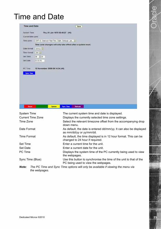
Time and Date
System Time The current system time and date is displayed.Current Time Zone Displays the currently selected time zone settings.Time Zone Select the relevant timezone offset from the accompanying drop
down menu.Date Format As default, the date is entered dd/mm/yy. It can also be displayed
as mm/dd/yy or yy/mm/dd.Time Format As default, the time displayed is in 12 hour format. This can be
changed to 24 hour if required.Set Time Enter a current time for the unit.Set Date Enter a current date for the unit.PC Time Displays the system time of the PC currently being used to view
the webpages.Sync Time (Blue) Use this button to synchronise the time of the unit to that of the
PC being used to view the webpages.Note: The PC Time and Sync Time options will only be available if viewing the menu via
the webpages.

Dedicated Micros ©201024
Ora
cle
User AccountsThe unit can protect configuration procedures by limiting access via usernames and passwords. By default, no usernames and passwords are configured for any account type.
Account Types The available account types for which users and passwords can be assigned privileges are:
Admin FTP Assigning username and password requirements for the Admin FTP function will limit access to the unit via an FTP connection.
Default Username:dmftp Default Password:ftp Telnet
Assigning username and password requirements for Telnet connections will limit Telnet access to the unit (Telnet can be used to upgrade the unit). Default Username:dm Default Password:telnet
WebPage Configuration Assigning WebPage Configuration privileges will limit access
to the Configuration menus when viewed remotely. When implemented, the user will be prompted for a username and password before access to the Configuration menus (via the main menu) will be granted. Default Username:dm Default Password:web
Serial Assigning username and password requirements for Serial
connections will limit access via a Serial link. No default username/password.

Dedicated Micros ©2010 25
Ora
cle
Admin Camera Protection Assigining a username and password protects camera
images from unauthorised access. No default username/password.
Note: Where there are no assigned, access will be granted to all users and no request for a username and password will be made.
Account List When an Account Type is highlighted, details of users with access will be displayed.
Add Highlight an administration feature i.e. Serial and select ‘Add’. Enter the new User Name and Password. That user’s name will now be displayed in the account list.
Modify/Delete To modify or delete a user’s settings, highlight the user in the list and press the relevant button to Modify or Delete.

Dedicated Micros ©201026
Ora
cle
Camera - StatusThis menu details information regarding the status of the Oracle IP Dome, notably the model type, current temperature and the version of software/firmware installed.
Camera Select a camera channel. The menu will only display successfully if the chosen camera channel has an Oracle Dome camera connected.
Camera Title Title assigned to the selected camera channel.Dome Model Details the product model.Dome Serial Number Identifies the serial number of the specific camera.Total Time On Details the operational life time of the camera to date.Total Time Active Details the total time the unit has been active (in motion).Time Since Restart Details the time since the camera was last reset.Current Temp Details the current temperature of the camera unit.Max Temp Details the maximum temperature the camera unit has reached.Min Temp Details the minimum temperature the camera unit has reached.Fan 1 Status Details the operational status of installed Fan 1.Fan 2 Status Details the operational status of installed Fan 2.Relay State Details the operational status of the camera unit’s relay. Software Version This identifies the version of software the camera unit is running.Firmware Version This identifies the version of firmware the camera unit is running.Bootloader Version This identifies the bootloader version of the camera unit
is running.Note: This web page is downloaded directly from the dome, NOT from the DM DVR/Server to which it is
attached. The live view window on the webpage will only update when the web page is loaded.

Dedicated Micros ©2010 27
Ora
cle
Camera - PresetsThis menu allows Preset positions to be configured and stored for the Oracle Dome camera.
Camera ID Selected camera channel.Camera Title Title assigned to the selected camera channel.Preset Select a preset number (1 to 100).Preset Name Enter a recognisable name for the Preset (up to a maximum of
25 characters).Note: The Oracle IP dome does not currently support on-screen message display, any text
entered as a preset name will not be displayed.+ (Red) Use the + button to zoom the camera view IN.- (Blue) Use the - button to zoom the camera view OUT.Navigation Buttons Use the four navigation buttons to position the camera view.Save (Grey) Select to save the entered preset title to the unit and the Oracle
Dome camera memory. Store Preset (Red) Select this button to store the current preset position to the Oracle
Dome camera’s memory. Goto Preset (Green) Select this button to immediately send the camera to the currently
stored preset position. Delete Preset (Yellow) Select this button to delete the currently displayed preset
configuration.Note: This web page should be accessed from the DM DVR/Server to which it is attached to be configured.

Dedicated Micros ©201028
Ora
cle
Camera - PatrolsThis menu allows camera patrol sequences to be established and configured for the Oracle Dome camera. The Patrol feature utilises established preset positions to automatically pan, tilt and zoom the camera in the selected sequence.
Camera Selected camera channel.Camera Title Title assigned to the selected camera channel.Patrol Up to four Patrol sequences can be established.Patrol Name Enter a recognisable name for the Patrol.Note: The Oracle IP dome does not currently support on-screen message display, any text
entered as a preset name will not be displayed.1-32 Up to 32 individual positioning manoeuvres can be added to
a Patrol.Note: Selecting one of the 1-32 buttons will send the camera to that Preset position.Preset Select a pre-established Preset.Speed Select the Speed the Patrol will progress to the next Preset
position (the speed can be set as a percentage of maximum capability).
Dwell Select the Dwell time (in seconds) the Patrol will remain at this Preset position.
Save (Grey) Select to store the preset sequence to the unit and the Oracle Dome camera memory.
Play (Red) Select to activate (play) the current patrol sequence.Note: This web page is downloaded directly from the dome, NOT from the DM DVR/Server to which it is
attached. The live view window on the webpage will only update when the web page is loaded.

Dedicated Micros ©2010 29
Ora
cle
Camera - Privacy MasksThis menu allows Privacy Masks to be established and configured for the Oracle Dome camera. The Privacy Mask feature can be used to ‘blank out’ sensitive or private areas which appear in the cameras field of view.
Camera Selected camera channel.Camera Title Title assigned to the selected camera channel.Mask Up to 24 separate masked areas can be created.Mask Colour The colour of the mask can be selected from the drop down list.
The default is black.Note: Select ‘Start New’ (Red) to begin creation of a privacy area. A black rectangle will then be displayed
superimposed across the camera view. It is recommended that the camera be navigated to the exact centre of the area requiring the privacy mask before pressing the ‘Start New’ button.
+ (Red) Use the + button to zoom the camera view IN.- (Blue) Use the - button to zoom the camera view OUT.Navigation Buttons Use the four navigation buttons to position the camera view.Note: When ‘Start New’ has been selected, the +/- and Navigation buttons can be used to set the
size and shape of the Privacy Mask. Save (Grey) Select to store the mask colour.Start New (Red) Select this option to begin creation of privacy mask.Finish New (Green) Select this option to finish creation of privacy mask.Show (Yellow) Select this option to show camera view with existing privacy
mask displayed.Delete (Blue) Select this option to delete the currently displayed privacy mask.Note: This web page should be accessed from the DM DVR/Server to which it is attached to be configured.

Dedicated Micros ©201030
Ora
cle
Camera - Camera SettingsThis menu allows settings for the Oracle IP Dome camera to be established and configured.
Camera Selected camera channel.Camera Title Title assigned to the selected camera channel.Backlight Comp Select to activate Backlight Compensation. This feature
compensates for back-lit scenes by enhancing objects which would previously have been in silhouette.
Auto Slow Shutter The Oracle Domes auto slow shutter feature enables the camera to automatically decrease the shutter speed in low light settings to help maintain quality of displayed images.
Auto Focus The Oracle Domes Auto Focus feature enables the camera to best focus on its current view. Select to activate.
Auto Flip When the Oracle Domes Auto Flip feature is activated, it will rotate a camera 180 degrees when it reaches its maximum upper or lower extremity i.e pointing directly upwards or downwards. This enables a camera to continue a tilt manoeuvre i.e. if tilting in an upwards direction, when the camera is pointing directly up, it will rotate 180 degrees and begin tilting in a downwards direction. If unselected, a camera will stop when it reaches its maximum upper or lower extremity.
HyperD Mode When selected, the dynamic range of the camera is increased. This feature is available on Day/Night cameras only.
Digital Zoom Select to activate the Digital Zoom function e.g. the camera will zoom within the actual image.

Dedicated Micros ©2010 31
Ora
cle
Optical Zoom Limit Select to limit the Oracle Domes optical zoom function. By default ‘100%’ is selected and the camera can zoom to its maximum capabilities. The optical zoom function can be limited to between 75% and 100% magnification.
ICR Oracle Domes with day/night cameras have an Infrared Cut Removal (ICR) function which can enhance the camera’s sensitivity in low light conditions as well as allowing infrared illumination to be used (infrared is blocked by the IR cut filter). When ICR is ON, the camera switches to monochrome mode, the IR cut filter is removed and the camera is at its most sensitive. The default setting for the camera is AUTO ICR where the filter is controlled automatically dependent on the scene brightness determined by the camera. The camera can be forced to stay in colour mode by setting ICR to OFF, or can be forced into mono with maximum low light sensitivity by setting ICR to ON.
Alternatively ICR switching can be triggered in response to an alarm input. This allows a photocell sensor to be connected to one of the dome’s alarm inputs to control the ICR. This method can be used to avoid instability that may occur when the camera controls the ICR switching in marginally low light conditions. Removing the IR cut filter due to low light can cause enough of an increase in scene brightness and video level to make the camera return the IR cut filter and switch immediately back to colour mode (at which point the video level drops and the process is repeated).
White Balance The Oracle Domes White Balance feature enables the camera to compensate for different lighting scenarios which can effect the colour quality of the displayed image. Select ‘Auto’ for the camera to auto-compensate for white balance depending on current view. Select ‘Indoor’ to permanently set for best results in an indoor setting. Select ‘Outdoor’ to permanently set for best results in an outdoor setting.
Exposure The Oracle Domes Exposure setting can be set to maintain optimum contrast settings for the viewed image/camera location. Select ‘Full Auto’ for the camera to auto-compensate for best exposure settings depending on current view. Select ‘Manual’ to manually configure exposure settings. Select ‘Shutter Priority’ to manually enter the shutter speed.
Shutter Speed If the Exposure feature is to be manually configured, enter the shutter speed settings.
Note: This web page is downloaded directly from the dome, NOT from the DM DVR/Server to which it is attached. The live view window on the webpage will only update when the web page is loaded.

Dedicated Micros ©201032
Ora
cle
Camera - Event SettingsThis menu allows actions to be established and configured for the Oracle Dome camera following an alarm event. A Home position can be established for the camera and the delay time set for what period of inactivity is required before the camera will be sent to its home position.
Camera Selected camera channel.Camera Title Displays the title assigned to the selected camera channel.Event Name If required, enter a specific name for the alarm event.Type Select the alarm type from:
EOL (End of Line), NC (Normally Closed), NO (Normally Open) or Disabled.
Enable Enables or disables monitoring of the alarm input. Action Select a preset position or a patrol action for the camera upon
alarm event. Relay Select an action for the relay. Select ‘Momentary’ for the relay to
momentarily switch state. Select ‘Duration’ to switch relay status for the duration of the alarm.
Home (Grey) Select to send the camera to its predetermined home position.Action Select a preset or patrol from the accompanying drop down list.
This preset/patrol will now be set as the cameras ‘home’ position.Delay Select the time ( in seconds) for which the camera is inactive i.e.
no operator input, before returning to its home position.Save (Grey) Select to store Event Settings to the unit and the Oracle Dome
camera memory. Note: This web page is downloaded directly from the dome, NOT from the DM DVR/Server to which it is
attached. The live view window on the webpage will only update when the web page is loaded.

Dedicated Micros ©2010 33
Ora
cle
NetworkThis menu allows network settings to be configured if required.
Server Name This field can be edited to allocate a name to the unit. This would be used if accessing the unit via a Domain Name Server (DNS).
IP Address This is the IP address allocated to the unit.Sub Net This is the subnet of the network were the unit is located. Gateway This is the IP address of the default gateway (router).DHCP If DHCP is being utilised, the assigned IP address will be
displayed here.Note: If no IP address is set, DHCP will automatically assign one. The unit interrogates the
network for a DHCP server, which assigns an available IP address. This IP address can change every time the unit is powered up. Therefore it is recommended that DHCP be disabled by entering a suitable, free, static IP address.
Tip: Use DHCP to locate a free IP address, then fix the unit IP address to the free one by entering the details into the IP address, subnet and gateway fields.
Primary DNS This is the primary DNS server IP address for applications utilising domain names.
Max Transmission Rate kbits sec This shows the maximum transmission speed for the network type being used.
Note: This setting will limit and override any higher transmission rate entered in the Video Transmission menu (Configuration menu->Video Trans).
Force 10BaseT operation The unit only supports 10BaseT half duplex transmission. Tx Image Buffers This is used in order to improve the picture delivery over Ethernet
when using a slow connection i.e. 256Kbps. A buffer setting of 1,2 or 3 is available (default = 1).

Dedicated Micros ©201034
Ora
cle
Video TransThe unit transmits live images using JPEG or MPEG formats. The NetVu Connected remote viewing software will use the settings configured on this page as the defaults for JPEG & MPEG; High, Medium and Low settings.
High LAN/Medium WAN/Low VLBR This shows the transmission settings configured for a High quality LAN (Local Area Network) connection, Medium quality WAN (Wide Area Network) connection or a Low quality VLBR (Very Low Bit Rate connection).
Comp Settings can be established for JPEG and MPEG compression.Res For MPEG and JPEG transmission, select image resolution
settings (4CIF, 2CIF, CIF or QCIF). Size_rate For JPEG, the figure entered will be the size of the JPEG
transmitted (in Kbytes). JPEG file sizes can be configured in the range of 5-45Kb. For MPEG4 the figure will be the bit rate allocated. A higher rate
will provide better quality picture display. MPEG bit rates in the range of 45-2500Kbits/second. PPS This shows the number of pictures transmitted per second.
For JPEG, the actual images transmitted will depend on the bandwith of the link, increasing the pictures sent per millisecond may introduce time lag if bandwith is not sufficient ie this forces the same quality image through the available connection. On MPEG transmission, increasing the pictures sent will also reduce the quality of the images ie this forces more images but maintains the defined bit rate.

Dedicated Micros ©2010 35
Ora
cle
MPEG Type & Quality Select whether transmitted MPEG4 images are sent as RAW data or in GOV (Group of Video) format. RAW mode transmits a single I frame and then a sequence of P frames (until a change in transmission is detected). GOV mode sends I and P frames in a standard format i.e. I to P frame ratio as set by the record parameters.
CBR maintains a Consant Bit Rate, selectable from a range of 2 - 31. Select a suitable level of details from the drop down list. Constant Bit rate allows the storage requirements to be calculated with more accuracy.

Dedicated Micros ©201036
Ora
cle
ConnectionsThis page shows the IP addresses of users connected to this unit. It is for information only and cannot be edited or configured.

Dedicated Micros ©2010 37
Ora
cle
AnalyticsDedicated Micros has created a range of analytics components and solutions designed to work with AnalyticsCapable products. The range of applications include: Automatic Number Plate Recognition (ANPR), Object Left and Removed, Access Control, People Counting and Perimeter Protection.
• For further information regarding the range of Dedicated Micros Analytics solutions, please call: + 44 (0) 845 600 9500

Dedicated Micros ©201038
Ora
cle
Viewer Defaults The units Viewer function allows remote users to simulate local operation over a network. This menu allows configuration of settings for the Viewer function, refer to ‘Operating The Viewer’ for more information regarding the Viewer.
Default Image Format Images from connected cameras can be displayed in either JPEG or MPEG format.
Default Image Req Images displayed full screen in the Viewer menus can be shown in either High Medium or Low resolution.
Applet Location The location of the unit’s Viewer menu applet is displayed. The default location will always be the applet hosted on a Dedicated Micros web server that is accessible from the Internet. However the applet may load faster if it is downloaded from the local DVR/Server to which the Oracle dome is attached. If accessing multiple units via a remote connection, all can be assigned the same Viewer applet. This will lessen the load time required when accessing different DVRs/Servers.
Reset (Red) This button will restart the unit.
To store a local version of the java applet1) Note the IP address of the DVR from the DVR ‘System’ web page. 2) Note the address of the applet from the DVR web pages on the ‘Viewer
Defaults’ tab of the Console settings.ie DVR/Server’s IP address is 192.168.0.11 enter the following into the Oracle’s viewer
defaults page to redirect the viewer. http://192.168.0.11/gui/viewer/applets/%OPERATING_SYSTEM%/viewer-applet.jar

Dedicated Micros ©2010 39
Ora
cle
Alternatively the applet may be downloaded from the DM website each time it is required when opening the dome’s web pages.
Note: This will require an Internet connection to be available. In which case the viewer default location should be; http://www.dedicatedmicros.com//software_release/%OPERATING_SYSTEM%/viewer-
applet.jar Or the applet can be downloaded from the DM web site and
stored locally on the computer that is being used to access the web pages from the dome. If the applet is stored in the C:\ folder of the PC then the viewer default location on the Oracle’s web pages should be
file:///C:/viewer-applet.jar

Dedicated Micros ©201040
Ora
cle
Go to ViewerThe unit can be viewed and accessed remotely via the webpages using the ‘Go to Viewer’ menu option.
The Java applet required to display live video will need to be downloaded from a remote host whenever the viewer page is accessed directly from the Dome. This will not apply if pages are called via a DVR.
When running the viewer that is served from the Oracle dome’s web pages (rather than running the viewer on the DVR) none of the coloured buttons will function, the viewer is only operational in full screen mode. The dome can be controlled either from the buttons on the remote control shown at the side of the dome, or by Point&go which will centre the camera’s field of view on the point clicked on in the viewer window.
Remote ViewerThe initial screen displays the video being sent from the unit.
Viewer FeaturesEptz Right clicking on the image will open the Electronic Zoom menu,
allowing the images to be zoomed in steps of 100%, 200%, 400% or 800%
Point&go When the zoom level is set to 100%, clicking on the image with the mouse will centre the image on the click point.

Dedicated Micros ©2010 41
Ora
cle
Key Button
Toggle the speed of PTZ camera movement (two speeds available).
Use the Zoom button to zoom in/out with a selected camera. Also used to zoom (x2) into Live or Playback images.
Press the Menu button to enter the Configuration menus.
Use the Directional buttons for PTZ telemetry control of cameras.
Remote ControlThe Remote Control offers control functionality.
Note: Not all buttons on this Remote Control are active.

Dedicated Micros ©201042
Ora
cle
Connecting to the IP Oracle DomeDVR Settings
The following pages demonstrate how to set up a compatable DVR to connect to an Oracle IP dome.
List of DVR’s required to utilise advanced programming features• SD Advanced, DV-IP Server, DV-IP HD, DV-IP RT and HighVu Excel running Gen3 pages.
Note: The pages shown are available off one of the DVR’s shown above. They are not stored on the Oracle Dome and are included for reference only.
Note: The dome is fitted with a bag of silica desiccant to absorb moisture. Ensure the cover is correctly refitted to the dome after any adjustment is made to avoid the desiccant becoming saturated.

Dedicated Micros ©2010 43
Ora
cle
CameraThis menu allows the configuration of active local camera channels. This page will only display the cameras connected to the DVR via the BNC connectors on the rear of the unit, cameras in non-local systems cannot be edited on this page.
Title Each of the camera titles can be edited for ease of use i.e. the camera type, location or view description could be used.
Note: If a camera title is entered via the local monitor, an on-screen virtual keyboard will be displayed to aid text entry.
Mode The settings will default to ‘Colour’. To connect an Oracle IP Dome, this should be set to ‘IP’.
Term The unit will automatically terminate a BNC camera input with 75Ω. An IP Camera such as the Oracle IP Dome does not require this.
Fail Rep Select this option to activate a Failure report in the event of camera connection failure (video loss).
Note: The arrow button displayed next to each textbox allows settings to be replicated for those cameras listed below. This will only affect the adjacent option i.e. Mode arrow will replicate the Mode setting to cameras below the clicked arrow.

Dedicated Micros ©201044
Ora
cle
IP CameraThis menu allows the configuration of connected IP Cameras (cameras connected directly to a network, broadcasting a digital video stream from an IP address). It can also connect to other NetVu Connected DVRs and treat one of the network feeds from that DVR as a digital video stream.
Title Displays the camera title.Mode Select the type of IP camera i.e. if the stream is originating from
a NetVu Connected server select ‘NetVu Server’. If from a NetVu camera such as a Dedicated Micros Oracle IP dome, select ‘NetVu Camera’.
URL Edit the URL address of the IP camera source.Port If required, edit the port input data. This will default to 80 (HTTP).Chan The Oracle IP dome only provides a single channel, set this
option to ‘1’.FPS Edit the FPS (Frames per Second) recording settings.

Dedicated Micros ©2010 45
Ora
cle
Camera TelemetryThis menu allows configuration of telemetry capable cameras and the assignment of telemetry protocols.
Cam Lists available camera channels. Note: Camera channels are displayed in groups of 8. Use the ‘1 to 8’, ‘1 to 12’ or ‘9 to 16’ buttons
to access all camera channels (if relevant to your unit).Title Titles assigned to each camera are displayed.Telemetry Select DM-IP telemetry to control the Oracle IP dome.Note: The arrow button displayed next to each textbox allows settings to be replicated for those
cameras listed below. This will only affect the adjacent option i.e. Telemetry arrow will replicate the Telemetry setting for cameras below the clicked arrow.

Dedicated Micros ©201046
Ora
cle
IP RecordThis menu enables the configuration of IP camera record settings.
Note: There is only normal ‘non event’ recording for connected IP cameras.
Channel Enables selection of a specific I.P camera for editing. Only cameras designated as I.P will be available.
Copy To All Select to copy the current record settings to all connected IP cameras.
Unset/Set/Override Normal This column shows the recording profile used by the camera when operating under Normal (non Event) conditions.
Comp Select image compression format (MPEG or JPEG).Res For both MPEG and JPEG recording, select either High, Medium
or Low quality resolution settings.Note: To view a local IP camera ‘live’, IP recording should be set to MPEG.

Dedicated Micros ©2010 47
Ora
cle
Using NetVu ObserverThe IP Oracle Camera produces a digital video stream from an independent IP address. NetVu ObserVer can connect directly to this video stream in the same way as it connects to a DVR. However, the camera needs to be within the same subnet as ObserVer.
The latest version of NetVu ObserVer can be downloaded free from the Dedicated Micros Website.
An Oracle IP dome can be added to NetVu ObserVer to allow the Operator to easily select the camera for viewing and control:
1. Highlight the Stored Image Servers Folder, or if a sub-folder (a folder within a folder) is required highlight the top level folder.
2. Click the right mouse button and select the Add Image Server option.3. Enter the IP address of the Oracle IP dome camera. Enter a suitable name to
identify the camera in the Site list.4. Click OK to enter these parameters. A shortcut to the camera will be displayed in
the Site List. A PTZ camera will be controllable via NetVu ObserVer. Alternatively, the IP address of the encoder can be entered into the dialog box on the bottom of the Image Server Tree pane. This will create a temporary connection to the camera. This can be made permanent by dragging the Entry into the Stored Image Servers folder.
These basic instructions will display the camera for viewing and control. For more information on the options available, refer to the NetVu ObserVer documentation.
Note: If a video account has been configured on the camera, a username and password will be requested when NetVu ObserVer connects

Dedicated Micros ©201048
Ora
cle
TroubleshootingDome spins continuously (DM controllers)
CauseNo joystick dead band recognized as joystick was off centre during power-up.
Solution
Reboot the controller with the joystick self centred
Dome loses IP addressCauseUnless a fixed IP address is configured in the dome via the ‘Network Settings’ web page, a dome that has been set to an address in the 169.254.5.x range will periodically check for the presence of a DHCP server and, if one is found, the dome will adopt the address allocated by the DHCP server regardless of the switch settings.
Solution
Add the correct IP address is configured in the Network Settings Web page.
CauseDHCP is enabled. This will cause the Dome to request an IP address from the DHCP server whenever it loses power. The DHCP server will not always return the same IP address.
Solution
Disable DHCP and set s fixed IP address.
Cannot change the dome system languageCauseDome hasn’t been rebooted after changing the settings on the Language web page.
Solution
Reboot the dome once the change have been made.

Dedicated Micros ©2010 49
Ora
cle
Appendix AControl Configuration - All Models
The unit arrives configured for use on a network with DNS or DHCP addressing. This information could be useful if neither of these options are available. It includes information on how to physically configure the dome to a fixed IP address.
Note: Ignore this section if using DHCP/DNS addressing. This information is only relevant when trying to access a dome for the first time on a network where DHCP is not available.
Note: The dome is fitted with a bag or silica dessicant to absorb moisture. Ensure the cover is correctly refitted to the dome after any adjustment is made to avoid the dessicant becoming saturated.
Switch settingsDifferent controllers require different protocols and a red rotary switch is provided to select the desired protocol. These are accessed by removing the outer hemisphere, refer to ‘Switch Configuration’ for more information. There are three color coded switches, red, blue and yellow, which are all located inside the dome camera housing. The blue and yellow switches have different functions, depending on the protocol selected by the red switch.
NOTE: Switches SW1, SW2 and SW3 are not operational on the IP version of the Oracle Dome
Switch ConfigurationTo access the address switches and termination switch, remove the outer hemisphere by unscrewing the six hemisphere securing screws. The location of the switches is shown. Access to the switches is improved if the inner shroud is removed by taking out the four securing screws. This operation should be carried out in an office type environment to avoid ingress of moist air.
RED SWITCH LOCATIONFunction - Protocol SelectionPosition Protocol E Ethernet

Dedicated Micros ©201050
Ora
cle
BLUE/YELLOW SWITCH LOCATIONFunction - Sets Default IP address if no DHCP is availableThe dome is configured to use IP address 169.254.5.0, which can be incremented up to 169.254.5.255 depending on the switch setting.
Address chartThe IP address (if no DHCP is available) will be 169.254.5.x, with the last byte of the address determined by the configuration of the Blue and Yellow switches. The default setting is 169.254.5.0.
0 1 2 3 4 5 6 7 8 9 10 11 12 13 14 15
16 17 18 19 20 21 22 23 24 25 26 27 28 29 30 31
32 33 34 35 36 37 38 39 40 41 42 43 44 45 46 47
48 49 50 51 52 53 54 55 56 57 58 59 60 61 62 63
64 65 66 67 68 69 70 71 72 73 74 75 76 77 78 79
80 81 82 83 84 85 86 87 88 89 90 91 92 93 94 95
96 97 98 99 100 101 102 103 104 105 106 107 108 109 110 111
112 113 114 115 116 117 118 119 120 121 122 123 124 125 126 127
128 129 130 131 132 133 134 135 136 137 138 139 140 141 142 143
144 145 146 147 148 149 150 151 152 153 154 155 156 157 158 159
160 161 162 163 164 165 166 167 168 169 170 171 172 173 174 175
176 177 178 179 180 181 182 183 184 185 186 187 188 189 190 191
192 193 194 195 196 197 198 199 200 201 202 203 204 205 206 207
208 209 210 211 212 213 214 215 216 217 218 219 220 221 222 223
224 225 226 227 228 229 230 231 232 233 234 235 236 237 238 239
240 241 242 243 244 245 246 247 248 249 250 251 252 253 254 255
Yellow
Blue
0 1 2 3 4 5 6 7 8 9 A B C D E F
0
1
2
3
4
5
6
7
8
9
A
B
C
D
E
F
To configure the IP address on the Oracle IP dome when DHCP automatic allocation is NOT avilable;
1. Determine an unused IP address by requesting a free address from the system administrator.
2. Refer to the table above to identify values for the blue and yellow switches coresponding to the IP address; blue switch setting is shown on the left, yellow switch setting on the right. For example, if the dome is to be used with IP address 169.254.5.132, the switches should be set to ‘84’. i.e. the blue switch should be set to ‘8’ and the yellow switch set to ‘4’.
3. Set the individual IP address for the dome on the blue and yellow switches fitted inside the dome housing.
Note: Unless a fixed IP address is configuredin the dome via the network settings web page, a dome that has been set to an address in the 169.254.5.x range will periodically check for the presence of a DHCP server and, if one is found, the dome will adopt the address allocatedby the DHCP server regardless of the switch settings.

Dedicated Micros ©2010 51
Ora
cle
Index18X zoom colour/mono camera......................................... 318X zoom day/night camera module ................................. 336X zoom day/night camera module ................................. 3Absolute Positioning .......................................................... 4Accessing the Configuration Web Pages ........................ 20Address chart .................................................................. 50Analytics .......................................................................... 37Appendix A....................................................................... 49BLUE/YELLOW SWITCH LOCATION ............................. 50Camera ............................................................................ 43Camera - Camera Settings .............................................. 30Camera Care ..................................................................... 6Camera - Event Settings ................................................. 32Camera - Patrols ............................................................. 28Camera - Presets ............................................................ 27Camera - Privacy Masks ................................................. 29Camera - Status .............................................................. 26Camera Telemetry ........................................................... 45Cannot change the dome system language .................... 48Cause .............................................................................. 48Components supplied - External ....................................... 7Components supplied - Internal......................................... 7Configuring the Unit ......................................................... 19Connecting the DVR to the Oracle Dome (via PCB) ......... 9Connecting to the IP Oracle Dome .................................. 42Connections..................................................................... 36Control Configuration - All Models ................................... 49Dome Configuration......................................................... 18Dome connector ................................................................ 8Dome loses IP address ................................................... 48Dome Mounting ............................................................... 13Dome Mounting ............................................................... 16Dome spins continuously (DM controllers) ...................... 48DVR Settings ................................................................... 42Electrical Connections - External....................................... 8Electrical Connections - Internal ...................................... 10ePTZ .................................................................................. 4FCC CLASS B REGULATORY NOTICE ........................... 5For standard ceiling mounted domes attach the supplied safety bond;................................................................................ 12For standard ceiling mounted domes attach the supplied safety bond;................................................................................ 15For wall, pendant & snowdrop mounted domes; ............. 12For wall, pendant & snowdrop mounted domes; ............. 15Function - Protocol Selection........................................... 49
Function - Sets Default IP address if no DHCP is available ....................................................................... 50Go to Viewer .................................................................... 40Introduction ........................................................................ 3IP Camera ............................................................................44IP Record ..............................................................................46Language......................................................................... 22List of DVR’s required to utilise advanced programming features ..................................................... 18List of DVR’s required to utilise advanced programming features ..................................................... 42Locating the Unit IP address ........................................... 19Minimum configuration ..................................................... 9Mounting Configurations - External ................................. 11Mounting Configurations - Internal .................................. 14Multiway connector .......................................................... 10Multiway Connector ........................................................... 8Network ........................................................................... 33Outline Specification: ........................................................ 3PCB ................................................................................... 9Pendant Mount ................................................................ 16Product Safety ................................................................... 4RED SWITCH LOCATION ............................................... 49Remote Control ............................................................... 41Remote Viewer ................................................................ 40RF Interference warning .................................................... 4RJ45 connectors.............................................................. 10Safety Bond ..................................................................... 12Safety Bond ..................................................................... 15Switch Configuration........................................................ 49Switch settings................................................................. 49System............................................................................. 21Tile Mount ........................................................................ 17Time and Date ................................................................. 23To configure the IP address on the Oracle IP dome when DHCP automatic allocation is NOT avilable; ............................................................... 50To store a local version of the java applet ....................... 38Troubleshooting ............................................................... 48User Accounts ................................................................. 24Using NetVu Observer ..................................................... 47Video Trans ..................................................................... 34Viewer Defaults .............................................................. 38Viewer Features .............................................................. 40

Dedicated Micros EuropeNeckarstrafle 15,
41836 Hückelhoven, Germany
Dedicated Micros France9-13 rue du Moulinet75013 Paris, France
Dedicated Micros SloveniaDelavska cesta 26,
4208 Sencure, Slovenia
Dedicated Micros BeneluxJoseph Chantraineplantsoen 1,
3070 Kortenberg, Belgium
Dedicated Micros USA.14434 Albemarle Point Place, Suite 100,
Chantilly, Virginia 20151 USA
Dedicated Micros, Australia PTY.5/3 Packard Avenue, Castle Hill,
NSW 2154, Australia
Dedicated Micros, Asia PTY16 New Industrial Road,
#03-03 Hudson Techno Centre,Singapore 536204
Dedicated Micros Middle EastBuilding 12, Suite 302, P.O. Box 500291, Dubai Internet
City, Dubai, United Arab Emirates
Dedicated Micros Ltd.1200 Daresbury Park, Daresbury,
Cheshire, WA4 4HS, UK
Installed by
MI-I-ODIP/E2-1
Dedicated Micros (Malta) Ltd.BLB017, Bulebel Industrial Estate,
Zejtun, ZTN08, Malta