Steam Turbine Solutions - Steam Turbine Engineering & Service

MK-Conversion
Reex-Fuss-TKS reserve all rights in this document and in the information contained therein. Reproduction, use or disclosure to third parties without express authority is strictly forbidden
Project Name: MK-CONVERSION
OPTIONS TO UTILIZE A STEAM TURBINE FROM A NUCLEAR POWER PLANT IN A NATURAL GAS FIRED POWER PLANT

MK-Conversion
2011-04-01 / Rev. e) 2011-04-30 HAEH200193 Page 2
Table of Content 1 Executive Summary 4
1.1 Short discussion of the recommended options 4 1.1.1 Option 1 (base option) 4 1.1.2 Option 2 5 1.1.3 Option 3 5 1.1.4 Option 4 5 1.1.5 Option 5 6 1.1.6 Option 6 and 7 6 1.1.7 Option 8 6
1.2 Net plant performance of the Options 7 1.3 Price differences and benefits of combined cycle Options 8 1.4 Option 8 - Gas fired boilers solution 9 1.5 Conclusions and Recommendations 9
1.5.1 Gas fired boiler solution 9 1.5.2 Combined cycle with E-class gas turbines 9 1.5.3 Combined cycle with F-class gas turbines 10 1.5.4 Duct firing 10 1.5.5 Preferred combined cycle Options 10
2 Introduction 11
3 Abbreviations 11
4 Limits 12
5 Technical Data of Mülheim-Kärlich Nuclear Plant 12
6 Conditions and Assumptions 14
6.1 Site conditions 14 6.2 Estimated performance for F-class gas turbine (corrected to site conditions) 15 6.3 Estimated performance for E-class gas turbine (corrected to site conditions) 16 6.4 HRSG design parameters 16
7 Utilization of the MK-Steam Turbine in a CCPP or GFSPP 17
8 Cycle Layout 17
8.1 Major equipment used in a combined cycle 18 8.1.1 Gas turbine 18 8.1.2 HRSG 18 8.1.3 Steam turbine 18 8.1.4 Condenser 19 8.1.5 Condensate extraction pump 19 8.1.6 Deaerator-feedwater-tank (only CCPP application) 20 8.1.7 Boiler feed pump 20

MK-Conversion
2011-04-01 / Rev. e) 2011-04-30 HAEH200193 Page 3
8.1.8 Plant arrangement 20 9 Description of the Options 21
9.1 Option 1 22 9.2 Option 2 23 9.3 Option 3 25 9.4 Option 4 26 9.5 Option 5 27 9.6 Option 6 29 9.7 Option 7 30 9.8 Option 8 31
10 Performance Summary 33
10.1 Performance with F-class gas turbines and gas fired boilers 33 10.2 Performance with E-class gas turbines 33 10.3 Influence of duct firing 34 10.4 Performance of the Gas fired boilers solution (Option 8) 35
11 Economical Evaluation 36
11.1 Options 1 to 5 (Combined cycle options) 36 11.2 Option 8 (Gas fired boilers solution) 37 11.3 Conclusions and recommendations 37
11.3.1 Gas fired boiler solution 37 11.3.2 Combined cycle with E-class gas turbines 38 11.3.3 Combined cycle with F-class gas turbines 38 11.3.4 Duct firing 38 11.3.5 Preferred combined cycle Options 38 11.3.6 Recommendation for project realization 39
12 Next steps and project outlook 40
13 Attachments 41

MK-Conversion
2011-04-01 / Rev. e) 2011-04-30 HAEH200193 Page 4
1 Executive Summary The target of this Feasibility Study is to identify options for the utilization of the retired steam turbine and some other equipment from the Mülheim-Kärlich Nuclear Power Plant in a new gas fired Combined Cycle or Steam Power Plant. In addition it should help to find the optimal solution with respect to technical and economical aspects.
Air intake, HRSG and stack of a F-Class CCPP
8 different Options were carefully studied by the authors to use the steam turbine in a gas fired combined cycle (Option 1 to 7) or in a steam power plant with gas fired boiler (Option 8). Option 1 with an absolute minimum of modifications at the steam turbine was selected as base option.
1.1 Short discussion of the recommended options
1.1.1 Option 1 (base option) The cycle presented with Option 1 is a 2P-NRH (dual pressure non reheat) cycle. Each gas turbine is connected to its own HRSG. In order to reduce the stack gas temperature as much as possible HP and LP-steam is produced. A further reduction of the stack gas temperature will be achieved by extracting feedwater for fuel gas preheating as well as preheating of condensate in the deaerator-feedwater-tank. Duct firing is not foreseen for Option 1.

MK-Conversion
2011-04-01 / Rev. e) 2011-04-30 HAEH200193 Page 5
We made the optimistic assumption, that the HP-turbine can be safely operated up to HP-steam temperatures of 470 °C. This assumption must be confirmed by a detailed analysis of the HP-turbine, if Option 1 would become the preferred solution.
Minimal required steam turbine modifications: • Options 1 to 7: Only one steam extraction would be used for preheating of the condensate
(lowest extraction), the other extractions would have to be closed and properly drained.
• Options 1 to 7: It is foreseen to produce LP-steam to improve the plant efficiency, which requiresnew stop and control valves. They would be connected to the crossover pipes to the LP-turbine.Adjustment of the hydraulic system would be required.
• All Options: The MK-water separator and superheater will not be used anymore, thus newcrossover pipes to the LP-turbine have to be installed.
1.1.2 Option 2 The cycle presented with Option 2 is similar to Option 1. The differences to Option 1 are the increased HP-steam conditions in order to improve the plant efficiency.
Required steam turbine modifications: • New inlet stop and control valves casings
• New connection piping between control valve and HP-casing
• Complete new turbine inner block (inner casing, turbine rotor and blading)
1.1.3 Option 3 The cycle presented with Option 3 is a 2P-NRH cycle. It is similar to Option 2, but the HRSG’s are equipped with duct burners in order to increase the plant output. Duct firing is a cost-effective option to produce peaking power.
Required steam turbine modifications: • New HP stop and control valves
• New connection piping between control valves and HP-casing
• Complete new turbine inner block (inner casing, turbine rotor and blading)
1.1.4 Option 4 The cycle presented with Option 4 is a 2P-NRH cycle. It is similar to Option 2. In order to avoid retrofitting of the existing HP-turbine (provided that the existing HP-turbine can be operated with an inlet temperature of at least 462 °C) a new topping turbine with generator for high inlet conditions is foreseen. Duct firing is not considered for Option 4.

MK-Conversion
2011-04-01 / Rev. e) 2011-04-30 HAEH200193 Page 6
Required steam turbine modifications and new components: • The existing stop and control valves will not be used anymore.
• New connection pipes from the exhaust of the new topping turbine to the inlet of the MK-HP-turbine
• New topping turbine with a speed of 3000 rpm and high steam parameters consisting mainly of:Stop and control valves
Topping turbine ~ 200 MW
Generator with a capability of at least 250 MVA and required electrical equipment
Complete auxiliary equipment to topping turbine
1.1.5 Option 5 The cycle presented under Option 5 is a 3P-RH (triple pressure reheat) cycle. With the reheat cycle we can expect the best possible cycle efficiency using the MK-steam turbine. Each gas turbine is connected to its own HRSG. Duct firing is not foreseen for Option 5.
Required steam turbine modifications and new components: • New stop and control valves for HP-steam
• New connection piping between HP-control valves and new HP-casing
• Complete new HP-turbine (outer and inner casing, turbine rotor and blading)
• New bearing pedestal between HP- and IP-turbine
• New intercept stop and control valves
• New connection piping between intercept-control valves and IP-turbine
• Complete new inner block for IP-turbine section (inner casing, turbine rotor and blading). Outercasing reused from MK-HP-turbine.
1.1.6 Option 6 and 7 The cycles presented under Option 6 and 7 are 3P-RH (triple pressure reheat) cycles. The idea was to use as much as possible from the existing MK-HP turbine. In order to reduce the inlet temperature into the existing HP-casing some stages have to be removed. As a result of the lower inlet pressure and temperature the steam velocity exceeded the allowable limit. Therefore options 6 and 7 are not feasible solutions and are not pursued anymore.
1.1.7 Option 8 This conventional non reheat steam cycle with gas fired steam boilers and unchanged HP-turbine would have to be operated with a HP-steam temperature of at least 508 °C to prevent severe erosion damage of the last stage blade of the LP-turbine. We have to assume that the existing HP-turbine without modifications can’t be safely operated (most probably) with such a high inlet temperature. The

MK-Conversion
2011-04-01 / Rev. e) 2011-04-30 HAEH200193 Page 7
required replacement of the HP-turbine internals allows an increase of the HP-steam conditions in order to achieve a better cycle efficiency.
Required steam turbine modifications: • New stop and control valves
• New connection pipes between control valves and HP-casing
• Complete new turbine inner block (inner casing, turbine rotor and blading)
The extraction steam temperatures to the HP-feedwater heaters would be at least 180 K (heater 6) resp. 140 K (heater 5) higher than in the original cycle. We have to assume that the heaters 5 and 6 have to be replaced.
1.2 Net plant performance of the Options Figure 1 shows the net plant output for the Options 1 to 7. Duct firing of Option 3 is not in service therefore the total fuel input into the cycle is identical for all Options.
Net Plant Output(Total fuel input = constant)
3643.2
3545.73543.33544.1
3438.5
3616.43633.3
3399.3
3294.53252.9
3000
3200
3400
3600
3800
4000
Option 1 Option 2 Option 3 Option 4 Option 5 Option 6 Option 7
Net
pla
nt o
utpu
t (M
W)
F-Class-gas turbine / No duct firing / Feasible solution
F-Class-gas turbine / No duct firing / Not feasible solution
E-Class-gas turbine / No duct firing / Feasible solution
Figure 1
It shows also that the net plant output with E-class gas turbines is in the range of 185 to 250 MW lower than with F-class units, resulting in a yearly loss of income in the range of 69 to 94 Mil €.
Retrofitting of the HP-turbine to allow increased HP-steam conditions (Options 2 to 4) results in increased net plant output of more than 100 MW
Option 5 (3P-RH-cycle) shows a net plant output of 3643 MW which is more than 200 MW higher than of Option 1.
Figure 2 shows the net plant output for Option 3 with and without duct firing. Up to 7 gas turbines in service it is possible to operate with maximal duct firing temperature. With more than 7 gas turbines in service the duct firing temperature has to be reduced to prevent overloading of the steam turbine

MK-Conversion
2011-04-01 / Rev. e) 2011-04-30 HAEH200193 Page 8
generator. With duct firing the net plant output can be increased up to 337 MW, corresponding to 12 % of the plant output, but the efficiency will become lower up to 2.2 %-points.
Option 3 / Net Plant Output with/without duct firing
1967.8
2758.7
3543.3 3597.3
2209.3
3095.5
1500
2000
2500
3000
3500
4000
5 7 9Number of gas turbines in service
Net
pla
nt o
utpu
t (M
W)
Net plant output / no duct firing Net plant output / maximal duct firing
Figure 2
Option 8 has a much lower fuel input compared to the combined cycle Options, thus the net plant output difference was determined for the maximal fuel input of Option 8. The diagram HAEH200198/39 shows an output difference of 626 MW at a fuel input of 3465 MW, resulting in an yearly loss of income of 235 Mio €.
1.3 Price differences and benefits of combined cycle Options The following Table 1 compares the Options 2 to 5 with the base Option 1 concerning plant output and efficiency and economical figures, which are based on assumed utilization of 7’500 hours/year and an electricity price of 50 €/MWh.
Option 1 Option 2 Option 3 Option 3 Option 4 Option 5
Number of F-class gas turbines in service 9 9 9 9 9 9
Duct firing on/off n/a n/a off on n/a n/a
Additional fuel input for duct firing at LOS 0.0 0.0 0.0 130.4 0.0 0.0 MW
Total fuel input at LOS 6383.8 6383.8 6383.8 6514.2 6383.8 6383.8 MW
Net plant output (low voltage side of step up) 3438.5 3544.1 3543.3 3597.3 3545.7 3643.2 MW
Net plant efficiency (low voltage side of step up) 53.9 55.5 55.5 55.2 55.5 57.1 %
Net plant output difference to Option 1 0 106 105 159 107 205 MW
Price difference to Option 1 0 +65 +88 +88 +67 +142 Mil Euro
Additional income per year 0 40 39 60 40 77 Mil Euro
Pay back period for additional investment 0 20 27 n/a 20 22 Month
Estimated investment cost 2000 2065 2088 2088 2067 2142 Mil Euro
Incremental project profit 0.00 1.92 1.88 2.85 1.95 3.58 %
Table 1 Performance summary CC-solutions

MK-Conversion
2011-04-01 / Rev. e) 2011-04-30 HAEH200193 Page 9
The pay back periods for performance improvement for each of the Options 2 to 5 are lower than 27 month.
Option 3: With duct firing it is possible to increase the net plant output up to 12 % but the net plant efficiency will be reduced up to 2.2 %-points. Duct firing is a cost effective option to produce peaking power.
1.4 Option 8 - Gas fired boilers solution Due to the design of the MK-steam turbine generator, the electric net power output of Option 8 is limited to 1238 MWe (maximal generator output of 1308 MW with PF = 0.8). The net plant efficiency would be only 35.7 % with an assumed boiler efficiency of 93 %.
• Electrical net plant output: 1238 MWe
• Net plant output difference to Option 1 626 MWe (Identical fuel input )
• Abs. net plant output difference to Option 1 2201 MWe
• Estimated investment cost 900 - 1100 Mil €
1.5 Conclusions and Recommendations
1.5.1 Gas fired boiler solution The gas fired boiler solution (Option 8) is no longer a state of the art solution, because of the poor efficiency compared with combined cycle applications. The maximal net plant output would be about 36 % compared with Option 1 with 9 F-class gas turbines. The net plant efficiency would be only 35.7 %, which is 18.6 %-points lower than of Option 1. Additionally Option 8 would require in any case similar steam turbine modifications like Option 2 or 3 to prevent severe erosion of the last stage blade of the LP-turbine. With the similar fuel input like Option 1 with 5 gas turbines in service (see HAEH200189/39) the yearly loss of income would be 235 Mio € per year. The lower investment cost would be highly compensated by the yearly loss of income.
==> Therefore we can not recommend the application of gas fired boiler solution (Option 8)
1.5.2 Combined cycle with E-class gas turbines The plant performance with E-class gas turbines would be lower (Figure 1) due to lower gas turbine efficiency and exhaust gas temperature:
• The net plant output would be 185 to 250 MW lower (depending on the Options), resulting in ayearly loss of income in the range of 69 to 94 Mil €
• Higher investment cost (14 instead of 9 gas turbines with HRSG’s, electrical equipment,foundations, piping systems …).
==> Therefore we can not recommend the installation of E-Class Heavy Duty Gas Turbines.

MK-Conversion
2011-04-01 / Rev. e) 2011-04-30 HAEH200193 Page 10
1.5.3 Combined cycle with F-class gas turbines With F-Class Heavy Duty Gas Turbines and retrofitted MK-steam turbine it would be possible to reach state of the art performance level of modern CCPP.
==> Our recommendation is to install F-class gas turbines
1.5.4 Duct firing Duct firing as exemplary shown with Option 3 is a cost effective solution to produce peaking power and is applicable to all CC-Options.
==> Our recommendation is to consider the implementation of duct firing related to the preferred Option.
1.5.5 Preferred combined cycle Options Option 2 requires less modifications of the steam turbine than option 5, thus the technical conversion risk is lower. The achievable efficiency is better than of Option 1 by 1.7 %-points however 1.5 %-points worse compared to Option 5. Option 2 is a feasible solution with lower investment cost and lower benefits.
From the different solutions in combined cycle mode Option 5 with F-class gas turbines shows the best result concerning on incremental project profit. With the additional investment of 142 Mio € an additional yearly income of 77 Mio could be generated; the pay back period for the additional investment would be 22 month.
Additional income compared to Option 1
0
20
40
60
80
Option 1 Option 2 Option 3 Option 4 Option 5
Add
ition
al in
com
e pe
r yea
r (M
io €
/y)
Incremental project profit
0
1
2
3
4
Option 1 Option 2 Option 3 Option 4 Option 5
Incr
emen
tal p
roje
ct p
rofit
(%)
Figure 3 Additional income Figure 4 Incremental project profit
Due to the size of the Power plant the economical figures are dominating the evaluation of the different Options.
==> Our recommendation is to choose Option 5 for further detailed analysis and engineering.
Recommendation for project realization In order to minimize the working capital we recommend a step by step power plant realization, starting with the installation of 5 F-Class gas turbines (Open cycle), followed by the extension to combined cycle plant. Afterwards the plant could be extended with to its full capacity (total 9 F-class gas

MK-Conversion
2011-04-01 / Rev. e) 2011-04-30 HAEH200193 Page 11
turbines). With such an approach revenue could be generated already in an early phase. The part load impact with only 5 gas turbines to the net plant efficiency in CC-mode is more or less negligible (< 0.3 %-points).
2 Introduction The target of this Feasibility Study is to show options for the utilization of the retired steam turbine and some other equipment from the nuclear power plant of Mülheim-Kärlich in a new gas fired combined cycle power plant. This report should help to find the optimal solution for the existing equipment to be used in a combined cycle or steam cycle power plant with respect to technical and economical aspects.
On the occasion of a meeting in Frankfurt, dated November 12, 2010 TKS, Fuss Energietechnik and Reex were assigned by 3Y to elaborate the first step of a Feasibility Study including the collection of all necessary data. The Study should address the following:
• Technical assessment of 7 defined options.
• For comparison reasons an additional Option (Option 8) with gas fired steam boilers should beincluded in the study (Request 3Y)
• Cost differential estimation between the options
• Commercial analysis based on technical assessments and cost estimation
• Propose 2-3 preferred options as result of this Feasibility Study
3 Abbreviations 2P-NRH Dual Pressure Non Reheat 3P-RH Triple Pressure Reheat CC Combined Cycle CCPP Combined Cycle Power Plant ETANet Net plant efficiency measured at low voltage side of step up transformer GFSPP Gas Fired Steam Power Plant GT Gas Turbine HP High Pressure HRSG Heat Recovery Steam Generator IP Intermediate Pressure LHV Lower Heating Value LP Low Pressure LSB Last Stage Blade of the steam turbine LOS Limit of supply MK Mülheim-Kärlich NG Natural Gas NRH Non Reheat Cycle OEM Original Equipment Manufacturer

MK-Conversion
2011-04-01 / Rev. e) 2011-04-30 HAEH200193 Page 12
PF Power Factor PNet Electrical net plant output measured at low voltage side of step up transformer PAux Auxiliary power of the plant RH Reheat Cycle ST Steam Turbine
4 Limits Fuel gas: After fuel gas reducing station or gas compressor, scrubbers, dew point heaters Cooling water: Inlet of main cooling water pumps Subsoil: Prepared, including piling if required Electrical: Connection of transmission lines to switchyard
5 Technical Data of Mülheim-Kärlich Nuclear Plant The Mülheim-Kärlich Nuclear Power Plant (Germany) was commissioned in 1987. After one year of operation the plant was shut down.
Nuclear reactor capacity 3789 MW
HP-steam production 2021 kg/s
HP-steam pressure 67.2 bar(a)
HP-steam temperature 311 °C
Reheat temperature at LP-inlet 256 °C
Steam turbine output at generator terminals (PF = 0.8) 1308 MW
Final feedwater temperature 237 °C
Turbine generator speed 1500 1/min
Generator capacity 1635 MVA
Nominal power factor 0.8
Cooling water flow 33778 kg/s
Condenser pressure 0.103 bar(a)
Table 2 Technical data of Mülheim-Kärlich
The detailed performance information of the nuclear cycle can be seen on the attached OEM heat balance ZW 91/001 3N. Based on this heat balance a turbine calculation model was set up. It was the requirement that the results of the model (swallowing capacity as well as efficiency of each blading section) comply exactly with the OEM heat balance in order to be able to accurately predict the performance of the steam turbine in its new environment.
The steam turbine was built for a nuclear cycle with low temperatures compared with fossil fuel fired steam plants or combined cycles power plants.

MK-Conversion
2011-04-01 / Rev. e) 2011-04-30 HAEH200193 Page 13
Because the HP-steam was only little superheated (~ 28 K) later stages in the HP-turbine had to be drained. The steam leaving the HP-turbine was led to the water separator and super-heater before entering the LP-turbine. To avoid severe erosion of the blading and inner casings drains were foreseen in the HP as well as LP turbine. The exhaust steam was condensed in a water cooled condenser. In order to improve the plant efficiency the feedwater was preheated.
Comparison of Steam Mass Flow
0
20
40
60
80
100
120
HP-inlet HP-Blading
section 1
HP-Blading
section 2
HP-Blading
section 3
HP-Blading
section 4
HP-Blading
section 5
LP-Blading
section 1
LP-Blading
section 2
LP-Blading
section 3
LP-Blading
section 4
LP-Blading
section 5
LP-LSB
Stea
m m
ass
flow
(%)
Nuclear cycle Mülheim Kärlich MK-Conversion, Option 1
Figure 5 Comparison of steam mass flow
Figure 5 compares the mass flow distribution from turbine inlet to the outlet of the combined cycle application (MK-conversion Option 1) with the situation as it was in the nuclear cycle of Mülheim-Kärlich. In the nuclear cycle application the steam flow decreases from 100 % (turbine inlet) to about 60 % (turbine exhaust), in the combined cycle application it increases slightly due to LP-steam admission.
The question my come up whether or not the lower inlet flow has a negative influence to the blading efficiency. The fact is that the blading efficiency is little affected by mass flow but it depends mainly on volume flow (velocity). Figure 6 shows that the volume flow difference between the nuclear and combined cycle application (Option 1) is low (similar velocity), therefore the influence to the blading efficiency is negligible.
Comparison of the Steam Volume Flow
0
1
2
3
4
5
HP-inlet HP-Blading
section 1
HP-Blading
section 2
HP-Blading
section 3
HP-Blading
section 4
HP-Blading
section 5
LP-Blading
section 1
LP-Blading
section 2
LP-Blading
section 3
LP-Blading
section 4
LP-Blading
section 5
LP-LSB
log1
0 (S
team
vol
ume
flow
)
Nuclear cycle Mülheim Kärlich MK-Conversion, Option 1
Figure 6 Comparison of steam volume flow

MK-Conversion
2011-04-01 / Rev. e) 2011-04-30 HAEH200193 Page 14
6 Conditions and Assumptions
6.1 Site conditions Since the location for the plant is not yet fixed, ambient- and cooling water temperature have been assumed, based on climate tables from several sites in Egypt (Figure 7 and 8).
14.0
16.0
18.0
20.0
22.0
24.0
26.0
28.0
30.0
32.0
34.0
0.0 2.0 4.0 6.0 8.0 10.0 12.0Month
Am
bien
t Tem
pera
ture
(°C
)
Alexandria: Average Day/Night temperature
Aswan: Average Day/Night temperature
Dahab: Average Day/Night temperature
Hurghada: Average Day/Night temperature
Sharm el Sheikh: Average Day/Night temperature
Average ambiet temperature
Ambient temperatures
Figure 7 Ambient temperatures for different sites
16.0
18.0
20.0
22.0
24.0
26.0
28.0
30.0
0.0 2.0 4.0 6.0 8.0 10.0 12.0
Month
Wat
er te
mpe
ratu
re (°
C)
Alexandria: Sea water
Aswan: High dam reservoir surface water temperature
Dahab: Sea water
Hurghada: Sea water
Sharm el Sheikh: Sea water
Average water temperature
Water temperatures
Figure 8 Water temperatures for different sites
The site conditions and fuel gas parameters as proposed in Table 3 were agreed with 3Y at a Meeting in Frankfurt from 15th of February 2011.

MK-Conversion
2011-04-01 / Rev. e) 2011-04-30 HAEH200193 Page 15
E- and F-class gas turbines are able to be operated with a fuel gas temperature of at least 150 °C,which improves the plant efficiency in the range of 0.5 to 0.6 % relative.
Ambient pressure 1013.25 mbar
Ambient temperature 25 °C
Relative humidity 60 %
Cooling water temperature 25 °C
Cooling water temperature rise < 8 K
Fuel gas temperature at LOS 15 °C
Fuel gas temperature after gas preheater 150 °C
Fuel gas pressure at LOS > 30 bar
Fuel gas LHV 46000 kJ/kg
Sulfor dioxide (SO2) in fuel gas 0.0 Nm3/Nm3
Table 3 Site conditions used for the Study
6.2 Estimated performance for F-class gas turbine (corrected to site conditions)
Today’s environmental situation requires that natural gas fired power plants operate with high efficiency. Therefore it is highly recommended to install F-class gas turbines for a power plant with a total output of more than 3000 MW.
Option 1, 2, 3, 4, Option 5, 6, 7
HRSG-type 2P-NRH 3P-RH
GT-inlet pressure drop 10 10 mbar
GT-outlet pressure drop 25 35 mbar
Fuel gas temperature at GT inlet 150 150 °C
Power output at generator terminals 260.366 258.626 MW
GT-efficiency 36.49 36.23 %
Exhaust gas flow 632.6 632.6 kg/s
Exhaust gas temperature 654.5 656.3 °C
Table 4 F-class gas turbine performance used for the study

MK-Conversion
2011-04-01 / Rev. e) 2011-04-30 HAEH200193 Page 16
6.3 Estimated performance for E-class gas turbine (corrected to site conditions)
E-class gas turbines have a lower output, efficiency and exhaust gas temperature. The lower exhaustgas temperature has the disadvantage, that the HRSG’s can not produce steam with state of the artHP- and reheat steam with temperatures of 565 °C, which is mandatory to accomplish a state of theart cycle efficiency. For comparison reasons some Options with E-class gas turbines were calculated.
Option 1, 2, 3, 4, Option 5, 6, 7
HRSG-type 2P-NRH 3P-RH
GT-inlet pressure drop 10 10 mbar
GT-outlet pressure drop 25 35 mbar
Fuel gas temperature at GT inlet 150 150 °C
Power output at generator terminals 160.997 160.447 MW
GT-efficiency 35.08 34.96 %
Exhaust gas flow 524.8 524.8 Kg/s
Exhaust gas temperature 535.4 536.8 °C
Table 5 E-class gas turbine performance used for the study
6.4 HRSG design parameters The figures according to Table 6 were used for the design of the HRSG’s. The performance of the gas turbines connected to triple pressure HRSG’s was adjusted for the assumed larger gas side pressure drop of the HRSG’s.
Gas side pressure drop for the dual pressure HRSG 25 mbar
Gas side pressure drop for the triple pressure reheat HRSG 35 mbar
Pinch point HP-cycle 8 K
Approach HP-cycle 4 K
Pinch point IP-cycle 10 K
Approach IP-cycle 5 K
Pinch point LP-cycle 10 K
Approach LP-cycle 5 K
Table 6 HRSG design parameters

MK-Conversion
2011-04-01 / Rev. e) 2011-04-30 HAEH200193 Page 17
7 Utilization of the MK-Steam Turbine in a CCPP or GFSPP In order to assure safe and reliable operation of the steam turbine the following limitations have been considered:
• Maximal exhaust steam flow of the ST = 1120 kg/s ==> Maximal 9 F-class or 14 E-class gasturbines can be installed to prevent overloading of the LSB of the steam turbine
• Maximal ST-Generator load = 1308 MW (PF = 0.8)
• Wetness after LSB < 12 % in the design point in order to prevent erosion damage of the LSB. Withlower cooling water temperatures the wetness will increase, but remains within acceptable range.
• The assumption was made, that the existing HP-turbine is able to be safely operated with amaximal HP-steam temperature (upstream stop valve) of 470 °C.
• Pressure at the inlet of the LP-turbine < 9.8 bar(a) (OEM-heat balance)
• The defined condenser design (identical for all Options) has to assure proper operation behaviourof the last LP-stages of the steam turbine.
8 Cycle Layout Considering today’s environmental situation it must be the target to convert the chemical energy of natural gas into electricity with the best possible efficiency. State of the art CCPP with F-Class gas turbines reach a net plant efficiency of 56 to 58 %. With the newest generation of gas turbines the net plant efficiency may even reach 60 %. It was agreed, that the newest generation of gas turbines shouldn’t be considered in this study.
Reex-Fuss-TKS investigated different options to utilize the MK-steam turbine in a CCPP as well as in a GFSPP, considering limitations of the existing equipment. The target is to reuse as much as possible equipment from the Mülheim-Kärlich plant (base Option), additionally options to improve the cycle efficiency should be proposed.
It is not intended to use the existing water separator/superheater in the new cycle due to the negative influence to the cycle efficiency. Therefore it is essential to increase the steam temperatures to avoid erosion of the steam turbine components and to improve the plant efficiency.
To prevent severe erosion of the last moving blade of the LP-turbine, the wetness of the last stages of the LP-turbine must be limited. The assumption was made that the wetness after the LSB should be lower than 12 % in the design point for this kind of LP-turbine.
Based on the OEM-heat balance the MK-Steam Turbine has a maximal exhaust steam flow of 1120 kg/s. To prevent overloading of the LSB the sum of the steam production minus extraction steam has to be lower than 1120 kg/s. Considering this restriction it is possible to maximal install 9 F-class or 14 E-class gas turbines. With F-class gas turbines a better performance can be expected than with E-class machines.

MK-Conversion
2011-04-01 / Rev. e) 2011-04-30 HAEH200193 Page 18
The Options 1 to 4 show a 2P-NRH-cycle, the Options 5 to 7 a 3P-RH-cycle. The HRSG’s from Option 3 are equipped with duct burners in order to increase the plant output, especially qualified for the production of peaking power.
The feedwater entering the HRSG’s may be as low as 60 °C. It is foreseen to preheat the condensate to 60 °C (corresponding to 0.2 bar(a)) in the existing deaerator-feedwater-tank. Probably adjustments of the deaerator section will be required.
For comparison reasons Option 8 with a gas fired boiler (GFSPP) is included in this study.
8.1 Major equipment used in a combined cycle
8.1.1 Gas turbine The cycle calculations were prepared with the typical performance of:
• 9 and 5 F-class gas turbines (Options 1 to 7)
• 14 and 8 E-class gas turbines (only Options 1, 2 and 5)
The gas turbine performance data used for the cycle calculations are listed in the tables 4 and 5.
To compare the different options the total fuel input into the gas turbines has been kept constant.
• Total fuel input into 9 F-class gas turbines = total fuel input into 14 E-class gas turbines
• Total fuel input into 5 F-class gas turbines = total fuel input into 8 E-class gas turbines
The maximal allowable exhaust steam flow of the steam turbine will be reached with 9 F-class gas turbines (Option 1). The other options have increased steam parameters resulting in a lower steam turbine exhaust flow. The lower exhaust gas temperature of the E-class gas turbines results also in a reduced steam production.
8.1.2 HRSG The basis for the design of the HRSG’s is summarized in Table 6. In order to achieve high cycle efficiency the stack gas temperature has to be as low as possible. With the installation of gas preheaters and the recirculation of LP-feedwater to the deaerator-feedwater-tank additional reduction of the stack gas temperature can be accomplished.
8.1.3 Steam turbine The MK-steam turbine is designed for steam temperatures lower than 320 °C. In a combined cycle application with natural gas as fuel it is important to operate the plant with a high efficiency in order to be competitive in the power generation market. To accomplish this it is essential to increase the steam temperatures as well as the steam pressures at turbine inlet.
We have seen before that in the combined cycle application the mass flow distribution in the turbine is different compared with the nuclear cycle. In the CC-application the end of the steam turbine is the

MK-Conversion
2011-04-01 / Rev. e) 2011-04-30 HAEH200193 Page 19
bottle neck concerning mass flow. For all Options the following restrictions must be considered to prevent damage of the MK-equipment:
• Maximal exhaust steam flow of the steam turbine = 1120 kg/s
• Maximal steam turbine generator load = 1308 MW with power factor = 0.8
• Wetness after LSB shall not exceed 12 % in design point
• Steam velocities must remain within acceptable range
• Higher steam temperatures than designed require a review of the affected components
• To reduce the stack gas temperature of the HRSG’s it is mandatory to preheat the condensate &feedwater in the colder zone of the HRSG’s, therefore the extractions 2 to 6 of the steam turbinehave to be closed and properly drained.
• Some driving steam from extraction 1 will be extracted to help to remove the accumulated waterfrom the LP-turbine. The steam together with the extracted water will be used to heat up thecondensate in the deaerator-feedwater-tank.
Minimal required steam turbine modifications: • Options 1 to 7: Only one steam extraction would be used for preheating of the condensate
(lowest extraction), the other extractions would have to be closed and properly drained.
• Options 1 to 7: It is foreseen to produce LP-steam to improve the plant efficiency, which requiresnew stop and control valves. They would be connected to the crossover piping to the LP-turbine.Adjustment of the hydraulic system would be required.
• All Options: The MK-water separator and superheater will not be used anymore, thus newcrossover pipes to the LP-turbine have to be installed.
8.1.4 Condenser In order to compare the performance of the eight options, the loading of the steam turbine LSB (exhaust loss) should be similar. In addition the condenser should be designed such, that no blocking in the LSB will occur over a wide operation rage. The attached Diagram HAEH200189/45 shows, that blocking will only occur with cooling water temperatures below 21 °C and exhaust steam flows from 900 to 1100 kg/s (9 F-class gas turbines in service). The chosen cooling water flow (constant for all Options) results in a cooling water temperature rise of less than 8K.
For all Options the identical condenser dimensions and cooling water inlet conditions have been used, therefore the condenser pressure depends only on the condenser duty.
8.1.5 Condensate extraction pump The condensate extraction pumps (4 x 33.3 %) forward the accumulated condensate from the condenser to the deaerator-feedwater tank. The required pump head is much lower than in MK, therefore new pumps have to be installed in order to reduce the auxiliary consumption (Except Options 8).

MK-Conversion
2011-04-01 / Rev. e) 2011-04-30 HAEH200193 Page 20
8.1.6 Deaerator-feedwater-tank (only CCPP application) The condensate is pumped from the condenser to the deaerator-feedwater-tank, where it is heated up to 60 °C, which is the minimal feedwater temperature to avoid condensation in the cold zone of the HRSG’s. The saturation pressure of 60 °C is 0.2 bar, the deaerator-feedwater-tank is under vacuum during operation. The heating medium to heat up the condensate to 60 °C comes from:
• Lowest extraction of the LP-turbine. To reduce risk of erosion damage of the LSB the accumulatedcondensate has to be extracted together with some driving steam.
• LP-economizer of the HRSG’s
8.1.7 Boiler feed pump The HP-feed pumps (4 x 33.3 %) forward the feedwater to the HP-economizer of the HRSG’s resp. to the gas fired boilers.
The LP-feed pumps (4 x 33.3 %) forward the feedwater to the LP-economizer (2P-NRH) resp. IP-economizer (3P-RH) of the HRSG’s.
8.1.8 Plant arrangement The attachments sketches HAEH200192/01 to 04 give a rough idea how the CCPP could be arranged, using F-class gas turbines. To avoid unnecessary long steam piping, five gas turbines with HRSG’s could be arranged on the right side, the other 4 on the left side of the steam turbine building.
HAEH200192/05 shows a possible arrangement of the GFSPP with 3 gas fired boilers.
The steam and water piping between steam turbine building and the HRSG’s resp. gas fired boilers will be arranged on pipe racks.

MK-Conversion
2011-04-01 / Rev. e) 2011-04-30 HAEH200193 Page 21
9 Description of the Options The Options have been calculated with the following assumptions:
• Site conditions as specified in Table 3
• F-class gas turbine performance as specified in Table 4
• E-class gas turbine performance as specified in Table 5
• Identical fuel input (Options 1 to 7). Option 3 has additional fuel input for duct firing
Fuel input for 9 F-class gas turbines = Fuel input for 14 E-class gas turbines
Fuel input for 5 F-class gas turbines = Fuel input for 8 E-class gas turbines
• HRSG design parameters as specified in Table 6
• Gas fired boiler efficiency = 93 %
• Performance of the HP-turbine as given in OEM-heat balance ZW 91/001 3N
• Performance of the LP-turbine as given in OEM-heat balance ZW 91/001 3N
• Estimated performance of new blading sections, considering increased axial expansion andavailable axial space in MK-HP-outer casing
• Identical condenser dimensions and materials as well as cooling water inlet conditions for allOptions
• Sliding pressure operation (HP and LP) according to Figure 9
0
20
40
60
80
100
120
0.0 1.0 2.0 3.0 4.0 5.0 6.0 7.0 8.0 9.0 10.0
Number of F-class gas turbines in service
HP-
stea
m p
ress
ure
(%)
Slising pressure operation
Fixed pressure operation
Sliding / fixed pressure operation
Figure 9 Sliding pressure operation

MK-Conversion
2011-04-01 / Rev. e) 2011-04-30 HAEH200193 Page 22
9.1 Option 1 The cycle presented with Option 1 is a 2P-NRH (dual pressure non reheat) cycle. Each gas turbine is connected to its own HRSG. HP-steam is produced (evaporation and superheating) in the high temperature section of the HRSG. In the lower temperature section the HP-feedwater is preheated. In order to reduce the stack gas temperature as much as possible also LP-steam is produced. A further reduction of the stack gas temperature will be achieved by extracting feedwater for fuel gas preheating as well as for condensate preheating in the deaerator-feedwater-tank. Duct firing is not foreseen for Option 1.
Figure 10 Option 1 (Dual pressure non reheat cycle)
The assumption was made that the HP-turbine from MK is able to be safely operated with increased steam temperature up to 470 °C. If Option 1 should finally be an economically interesting solution careful stress analysis of the HP-stop and control valves, connection piping from valve casing to HP-turbine, inner and outer HP-casing, rotor and HP-blading will be necessary. In addition the axial differential expansion has to be revived carefully.
The produced HP-steam from the HRSG’s is collected in 2 headers which are arranged on each side of the steam turbine. The stop valves of the steam turbine are connected to the headers with four pipes.
The LP-steam is collected in a common pipe which is directly connected to the new LP-stop valves. Connection pipes from the LP-control valves to the new crossover pipes between HP- and LP-turbine are required.
Since the HP-steam flow in CC-mode is only 60 % of the steam flow as it was in MK (Figure 5) the HP-steam pressure will be lower than in MK. In order to prevent the LSB from severe erosion the exhaust wetness must be limited. The attached diagram HAEH200189/37 shows that the HP-steam temperature has to be increased to 470 °C to reduce the exhaust wetness to 12 %. The wetness depends mostly from the HP-steam conditions and from the condenser pressure. During wintertime the cooling water temperature may drop down to 16 °C, resulting in a lower condenser pressure and increased exhaust wetness (HAEH200189/38).

MK-Conversion
2011-04-01 / Rev. e) 2011-04-30 HAEH200193 Page 23
According to Figure 5 the LP-inlet flow is marginal higher then the HP-exhaust flow, i.e. the LP-steam production is little. With a single pressure HRSG (no LP-steam production) the plant output would be reduced by ~ 9.2 MW, the net plant efficiency by ~ 0.14 %-points with the maximal numbers of gas turbines in service.
The heat balances HAEH200181/01 and /02 show the plant performance with 9 respectively 5 F-class gas turbines in service.
The heat balances HAEH200181/11 and /12 show the plant performance with 14 respectively 8 E-class gas turbines in service.
The diagram HAEH200189/36 shows the net cycle performance vs. the number of F-class and E-class gas turbines in service. Over a wide operation range (Fuel input = 3500 to 6400 MW) a constant plant efficiency can be expected.
Expected scope for Option 1: • 9 F-Class gas turbines
• 9 dual pressure non reheat HRSG’s without duct firing
• Minimal modification of MK steam turbine
• Complete Balance of Plant
• Instrumentation
• Complete electric part (MCC, DCS, power and control cabling)
• Step up and auxiliary transformers
• Switchyard
• Civil part
9.2 Option 2 The cycle presented with Option 2 is a 2P-NRH cycle. Each GT is connected to its own HRSG. HP-steam is produced (evaporation and superheating) in the high temperature section of the HRSG, in the lower temperature section the HP-feedwater is preheated. In order to reduce the stack gas temperature as much as possible also LP-steam is produced. A further reduction of the stack gas temperature will be achieved by extracting feedwater for fuel gas preheating as well as for condensate preheating in the deaerator-feedwater-tank. Duct firing is not foreseen for this Option.
In order to increase the plant efficiency of Option 1 the HP-steam pressure and -temperature have to be increased, thus the following components have to be replaced / new installed:
• HP-stop- and control valves
• Piping between control valves and HP-casing
• HP-Inner casing with stationary blading
• HP-rotor with rotating blading

MK-Conversion
2011-04-01 / Rev. e) 2011-04-30 HAEH200193 Page 24
Figure 11 Option 2 (Dual pressure non reheat cycle)
With HP-steam temperatures of 565 °C the HP-steam pressure must be lower than 82 bar(a) in order to prevent severe erosion of the LSB.
The heat balances HAEH200182/01 and /02 show the plant performance with 9 respectively 5 F-class gas turbines in service.
The heat balances HAEH200182/11 and /12 show the plant performance with 14 respectively 8 E-class gas turbines in service.
The diagram HAEH200189/35 shows the net cycle performance for different number of F-class resp. E-class gas turbines in service.
Expected scope for Option 2: • 9 F-Class Gas Turbines
• 9 dual pressure non reheat HRSG’s without duct firing
• Modified MK steam turbine (Retrofit of HP-turbine, see above)
• Complete Balance of Plant
• Instrumentation
• Complete electric part (MCC, DCS, power and control cabling)
• Step up and auxiliary transformers
• Switchyard
• Civil part

MK-Conversion
2011-04-01 / Rev. e) 2011-04-30 HAEH200193 Page 25
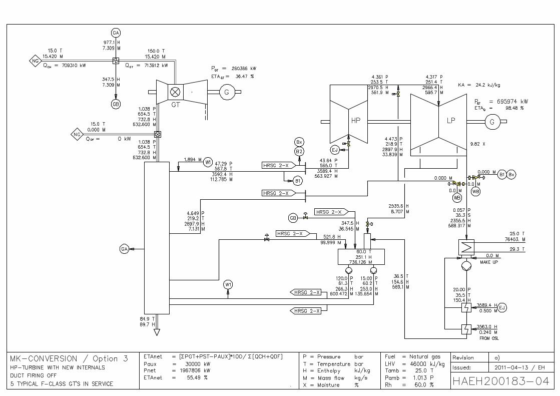
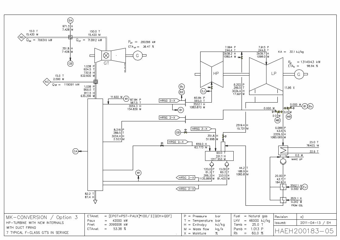
9.3 Option 3 The cycle presented with Option 3 is a 2P-NRH cycle. It is similar to Option 2, but the HRSG’s are equipped with duct burners in order to increase the plant output.
Because of the increased HP-steam parameters the following components have to be replaced / new installed:
• HP-stop- and control valves
• Piping between control valves and HP-casing
• HP-Inner casing with stationary blading
• HP-rotor with rotating blading
Figure 12 Option 3 (Dual pressure non reheat cycle with duct firing)
With HP-steam temperatures of 565 °C the HP-steam pressure must be lower than 82 bar(a) in order to prevent severe erosion of the LSB.
The attached heat balances HAEH200183/01 show the cycle performance with 9 F-class gas turbines in service. The maximal duct firing temperature has to be limited to 673 °C to prevent overloading of the generator. The heat balance HAEH200183/02 shows the cycle with only 5 gas turbines in service with maximal duct firing of 800 °C.
The heat balances HAEH200183/03 and /04 show the plant performance without duct firing.
With 7 F-class gas turbines and the HRSG’s with maximal duct firing (800 °C) the output exceeds somewhat the nominal generator load of 1308 MW (HAEH200183/05).
The diagrams HAEH200189/46 and /47 show the influence of duct firing to the plant performance with F-class gas turbines. With the maximal duct firing temperature of 800 °C the net plant output will beincreased up to 12.2 % but the net plant efficiency drops up to 3.9 % relative.

MK-Conversion
2011-04-01 / Rev. e) 2011-04-30 HAEH200193 Page 26
Expected scope for Option 3: • 9 F-Class Gas Turbines with duct fired HRSG
• 9 dual pressure non reheat HRSG’s with duct firing
• Modified MK steam turbine (Retrofit of HP-turbine, see above)
• Balance of Plant
• Instrumentation
• Complete electric part (MCC, DCS, power and control cabling)
• Step up and auxiliary transformers
• Switchyard
• Civil part
9.4 Option 4 The cycle presented with Option 4 is a 2P-NRH cycle. It is similar to Option 2. In order to avoid retrofitting of the existing HP-turbine (provided that the existing HP-turbine can be operated with an inlet temperature of at least 462 °C) a new topping turbine with generator for high inlet conditions could be installed. Duct firing is not foreseen for Option 4.
To limit the exhaust wetness to 12 % the HP-steam pressure upstream the stop valves of the topping turbine must be lower than 82 bar(a) with a HP-steam temperature of 565 °C.
Figure 13 Option 4 (Dual pressure non reheat cycle with new topping turbine)

MK-Conversion
2011-04-01 / Rev. e) 2011-04-30 HAEH200193 Page 27
Required steam turbine modifications and new components: • The existing stop and control valves will not be used anymore.
• New connection pipes from the exhaust of the new topping turbine to the inlet of the MK-HP-turbine
• New topping turbine with a speed of 3000 rpm and high steam parameters consisting mainly of:
Stop and control valves
Topping turbine ~ 200 MW
Generator with a capability of at least 250 MVA and required electrical equipment
Complete auxiliary equipment
The attached heat balances HAEH200184/01 and /02 show the plant performance with 9, respectively 5 F-class gas turbines in service.
The diagram HAEH200189/34 shows the net cycle performance for different number of F-class and E-class gas turbines.
Expected scope for Option 4: • 9 F-Class Gas Turbines
• 9 dual pressure non reheat HRSG’s without duct firing
• Modified MK steam turbine and new topping turbine (see above)
• Balance of Plant
• Instrumentation
• Complete electric part (MCC, DCS, power and control cabling)
• Step up and auxiliary transformers
• Switchyard
• Civil part
9.5 Option 5 The cycle presented under Option 5 is a 3P-RH (triple pressure reheat) cycle. With the reheat cycle we can expect the best possible cycle efficiency using the MK-steam turbine.
Each gas turbine is connected to its own HRSG. In the high temperature section of the HRSG HP-steam (evaporation and superheating) is produced and the cold reheat and IP-steam reheated. In the lower temperature sections of the HRSG, feedwater is preheated as well as IP- and LP-steam produced. A further reduction of the stack gas temperature will be achieved by extracting feedwater for fuel gas preheating as well as preheating of condensate in the deaerator-feedwater-tank. Duct firing is not foreseen for Option 5.

MK-Conversion
2011-04-01 / Rev. e) 2011-04-30 HAEH200193 Page 28
Figure 14 Option 5 (Triple pressure reheat cycle)
In order to realize the maximal plant efficiency HP-steam pressure and temperature have to be increased. To avoid too high LP-inlet steam temperature (Hot reheat steam temperature of 565 °C) the minimal IP-turbine inlet pressure has to be higher than 33 bar(a). The assumption has been made, that the temperature at the LP-inlet should not exceed 350 °C. If this option should be an economically interesting solution the MK-HP-outer casing and the LP-inlet section must be reviewed carefully.
Required steam turbine modifications and new components: • New HP-Turbine with stop and control valves. The front end of the new HP-rotor should fit into the
existing front bearing pedestal.
• A new bearing pedestal between HP- and IP-turbine
• New Intercept stop- and control valves for the IP-turbine
• New inner block for the IP-turbine (Inner casing, rotor and blading)
The outer casing from the existing HP-turbine would be used as the outer casing for the IP-turbine.
The limit for the maximal HP-steam pressure is the available axial space in the new HP-casing.
With F-class gas turbines steam temperatures of 565 °C for HP- and reheat steam can be reached Due to the high hot reheat temperature of 565 °C the wetness after LSB will be lower than 9 %.
The heat balances HAEH200185/01 and /02 show the plant performance with 9 respectively 5 F-class gas turbines in service.
Steam temperatures of maximal 515 °C (HP- and reheat steam) can be reached with E-class gas turbines since the exhaust gas temperature is more than 100 K lower than with F-class gas turbines.
The heat balances HAEH200185/11 and /12 show the plant performance with 14 respectively 8 E-class gas turbines in service.

MK-Conversion
2011-04-01 / Rev. e) 2011-04-30 HAEH200193 Page 29
The larger performance difference compared with Option 1 is based on the fact that the exhaust gas temperatures of the E-class gas turbines are too low to produce HP- and reheat steam with a temperature of 565 °C.
The diagram HAEH200189/48 shows the net cycle performance for different number of F-class and E-class gas turbines in service.
With 9 F-class gas turbines in service the generator of the steam turbine will be overload by 4.7 % when operating with a power factor of 0.8
Expected scope for Option 5: • 9 F-Class Gas Turbines
• 9 Triple pressure reheat HRSG’s without duct firing
• Modified MK steam turbine (see above)
• Balance of Plant
• Instrumentation
• Complete electric part (MCC, DCS, power and control cabling)
• Step up and auxiliary transformers
• Switchyard
• Civil part
9.6 Option 6 The cycle presented with Option 6 is a 3P-RH cycle. It is similar to Option 5 with the same HP- and reheat-steam conditions.
Figure 15 Option 6 (Triple pressure reheat cycle with new HP / IP1 turbine)
MK-Conversion
2011-04-01 / Rev. e) 2011-04-30 HAEH200193 Page 30
To reuse the MK-HP-turbine without major changes it was the idea to split the IP-expansion into two sections (IP1 and IP2). HP and IP1 are installed in a new casing. The existing HP-turbine (some stages removed) is used as IP2. The inlet temperature of IP2 should not exceed 480 °C, assuming the existing HP-turbine (now IP2) can be safely operated with an inlet temperature of 480 °C (see Option 1).
The heat balances HAEH200186/01 and /02 show the plant performance with 9 respectively 5 F-class gas turbines in service.
Required steam turbine modifications and new components: • A complete new combined HP/IP1-turbine with stop- and control valves (HP and Hot reheat)
• New bearing pedestal between IP1 and IP2.
The limit for the maximal HP-steam pressure is the available space for the HP-blading.
The existing HP-turbine will be used as second part of the IP-turbine (IP2)
Due to the high hot reheat temperature of 565 °C the wetness after LSB will be lower than 9 %.
To limit the temperature at the inlet of IP2 to 480 °C, some stages of the existing HP have to be removed with the effect that the steam velocity at the inlet of the existing HP-casing exceeds by far the maximal tolerated value of 60 m/s.
==> Option 6 is not a feasible solution and will not be pursued.
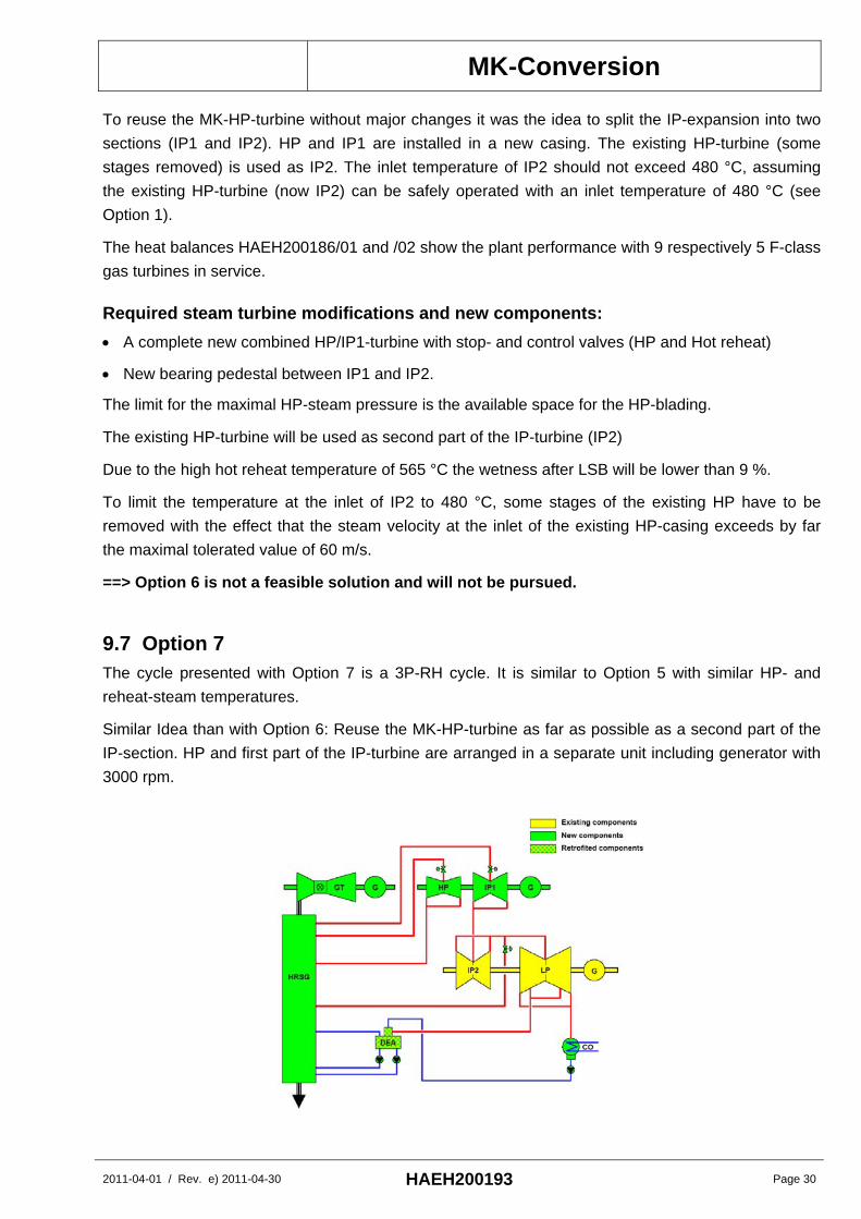
9.7 Option 7 The cycle presented with Option 7 is a 3P-RH cycle. It is similar to Option 5 with similar HP- and reheat-steam temperatures.
Similar Idea than with Option 6: Reuse the MK-HP-turbine as far as possible as a second part of the IP-section. HP and first part of the IP-turbine are arranged in a separate unit including generator with 3000 rpm.

MK-Conversion
2011-04-01 / Rev. e) 2011-04-30 HAEH200193 Page 31
Figure 16 Option 7 (Triple pressure reheat cycle with new separate HP / IP1 turbine)
In order to reduce the steam velocity at the inlet of the MK-HP-turbine less stages have been removed (compared with Option 6) with the disadvantage that the inlet temperature exceeds 480 °C, which is for the existing HP-rotor, inner casing and blading not acceptable. Even with the increased inlet pressure the velocity is still 100 m/s, which is not acceptable.
The heat balances HAEH200187/01 and /02 show the plant performance with 9 respectively 5 F-class gas turbines in service.
==> Option 7 is not a feasible solution and will not be pursued.
9.8 Option 8 As a request from 3Y the performance for the use of the MK-steam turbine together with a natural gas fired boiler should be calculated as a reference.
The efficiency of such conventional steam cycle (GFSPP) is lower than of a CCPP. Since the fuel cost for natural gas has increased dramatically in the last 20 years, GFSPP became more and more uneconomical. Repowering (replacement of gas fired boilers with gas turbines and HRSG’s) of such plants was the only option make such plants profitable again.
In a conventional steam cycles the condensate and feedwater is preheated with steam extracted from the steam turbine. The flow distribution through the turbine is similar as shown on Figure 5 for the nuclear cycle.
Figure 17 Option 8 (Conventional non reheat steam cycle with gas fired boiler)
Using the existing HP-turbine without modification the HP-steam temperature has to be increased to 508 °C (HAEH200191/01) to prevent severe erosion damage of the last stage blade of the LP-turbine. We have to assume that the existing HP-turbine without modifications can’t be safely operated (most probably) with such a high inlet temperature. The required replacement of the HP-turbine internals allows an increase of the HP-steam conditions in order to achieve a better cycle efficiency.

MK-Conversion
2011-04-01 / Rev. e) 2011-04-30 HAEH200193 Page 32
The heat balances HAEH200191/11 show the maximal plant output with gas fired boilers. The maximal output is limited by the existing generator to 1308 MW (PF = 0.8).
The extraction steam temperature to the HP-preheaters would be increased up to 180 K. We have to assume that the HP-heaters have to be replaced.
Required steam turbine modifications and new steam turbine components: • HP-stop- and control valves
• Piping between control valves and HP-casing
• HP-Inner casing with stationary blading
• HP-rotor with rotating blading
Expected scope for Option 8: • 3 gas fired HP steam boilers
• Modified MK steam turbine (see above)
• Balance of Plant
• Instrumentation
• Complete electric part (MCC, DCS, power and control cabling)
• Step up and auxiliary transformers
• Switchyard
• Civil part

MK-Conversion
2011-04-01 / Rev. e) 2011-04-30 HAEH200193 Page 33
10 Performance Summary
10.1 Performance with F-class gas turbines and gas fired boilers Option 1 Option 2 Option 4 Option 5 Option 6 Option 7 Option 8
Heat balanceHAEH200181
HAEH200182
HAEH200183
HAEH200183
HAEH200184
HAEH200185
HAEH200186
HAEH200187
HAEH200191
Sheet 01 01 03 01 01 01 01 01 11
Revision - - a) a) a) c) a) a) b)
Number of F-class gas turbines in service 9 9 9 9 9 9 0
HP-steam pressure at steam turbine stop valve 46.5 82.0 78.0 81.7 83.0 148.5 141.0 120.3 82.0 bar
HP-steam temperature at steam turbine stop valve 470 565 565 565 565 565 565 563 565 °C
Hot reheat steam temperature at intersept stop valve n/a n/a n/a n/a n/a 565 565 565 n/a °C
Total fuel input for gas turbines at LOS 6383.8 6383.8 6383.8 6383.8 6383.8 6383.8 6383.8 6383.8 0 MW
Additional fuel input for duct firing at LOS 0 0 0 130.4 0 0 0 0 0 MW
Total fuel input for gas fired steam boilers at LOS 0 0 0 0 0 0 0 0 3465.2 MW
Total power output at generator terminals of gas turbines 2343.3 2343.3 2343.3 2343.3 2343.3 2327.6 2327.6 2327.6 0 MW
Power output at generator terminals of MK-steam turbine 1149.2 1254.8 1254.0 1308.0 1052.5 1369.6 1359.6 1001.9 1308.0 MW
Power output at generator terminals of topping turbine 0 0 0 0 204.0 0 0 340.9 0 MW
Estimated plant auxiliary power 54.0 54.0 54.0 54.0 54.0 54.0 54.0 54.0 70.0 MW
Net plant output (low voltage side of step up transformer) 3438.5 3544.1 3543.3 3597.3 3545.7 3643.2 3633.3 3616.4 1238.0 MW
Wetness after last stage blade 12.0 12.0 11.7 11.8 12.0 7.7 8.4 8.2 12.1 %
Net plant efficiency (low voltage side of step up transformer) 53.86 55.52 55.50 55.22 55.54 57.07 56.91 56.65 35.73 %
Net plant output difference to Option 1 0 105.6 104.8 158.9 107.3 204.7 194.8 177.9 -625.6 MW
CommentNo
ductfiring
Withductfiring
Notfeasile
solution
Notfeasilesolution
seeHAEH
200189/39
Option 3
9
Table 7 Performance summary with F-class gas turbines and gas fired boiler
10.2 Performance with E-class gas turbines Option 1 Option 2 Option 5
DWG-Nr HAEH200181
HAEH200182
HAEH200185 0
Sheet 11 11 11 0
Revision a) a) a) 0
Number of E-class gas turbines in service 14 14 14 0
HP-steam pressure at steam turbine stop valve 40.9 57.0 148.5 bar
HP-steam temperature at steam turbine stop valve 470 512 515 °C
Hot reheat steam temperature at intersept stop valve n/a n/a 515 °C
Total fuel input for gas turbines at LOS 6383.8 6383.8 6383.8 MW
Total fuel input for supplementary firing at LOS 0 0 0 MW
Total fuel input for gas fired steam boilers at LOS 0 0 0 MW
Total power output at generator terminals of gas turbines 2254.0 2254.0 2246.3 MW
Power output at generator terminals of MK-steam turbine 1052.9 1094.5 1207.0 MW
Power output at generator terminals of topping turbine 0 0 0 MW
Estimated plant auxiliary power 54 54 54 MW
Net plant output (low voltage side of step up transformer) 3252.9 3294.5 3399.3 MW
Net plant efficiency (low voltage side of step up transformer) 50.96 51.61 53.25 %
Wetness after last stage blade 11.5 12.0 10.1 %
Output difference to Option 1 0.0 41.6 146.4 MW
Output difference compared to F-class gas turbines -185.6 -249.6 -243.9 MW
Rel efficiecy compared with F-class gas turbines -5.4 -7.0 -6.7 %
Table 8 Performance summary with E-class gas turbines

MK-Conversion
2011-04-01 / Rev. e) 2011-04-30 HAEH200193 Page 34
Figure 18 (same as figure 1) shows the net plant output for the Options 1 to 7. Duct firing of Option 3 is not in service therefore the total fuel input into the cycle is identical for all Options.
Net Plant Output(Total fuel input = constant)
3643.2
3545.73543.33544.1
3438.5
3616.43633.3
3399.3
3294.53252.9
3000
3200
3400
3600
3800
4000
Option 1 Option 2 Option 3 Option 4 Option 5 Option 6 Option 7
Net
pla
nt o
utpu
t (M
W)
9 F-Class-gas turbine / No duct firing / Feasible solution
9 F-Class-gas turbine / No duct firing / Not feasible solution
14 E-Class-gas turbine / No duct firing / Feasible solution
Figure 18 Net plant output with F- and E-class gas turbines
It shows also that the net plant output with E-class gas turbines is in the range of 185 to 250 MW lower than with F-class units, resulting in a yearly loss of income in the range of 69 to 94 Mil €.
Retrofitting of the HP-turbine to allow increased HP-steam conditions (Options 2 to 4) results in increased net plant output of more than 100 MW
A complete new steam turbine generator with 3000 rpm (Option 4) does not improve the plant performance.
Option 5 (3P-RH-cycle) shows a net plant output of 3643 MW which is more than 200 MW higher than of Option 1.
10.3 Influence of duct firing The Figures 19 and 20 show the net plant performance for Option 3 with and without duct firing. Up to 7 gas turbines in service it is possible to operate with maximal duct firing temperature. With more than 7 gas turbines in service the duct firing temperature has to be reduced to prevent overloading of the steam turbine generator. With duct firing the net plant output can be increased up to 337 MW (see HAEH200189/46), corresponding to 12 % of the plant output, but the efficiency will be lower up to 2.2 %-points (HAEH200189/47).
With 9 F-class gas turbines in service it is not possible to operate all HRSG’s at with maximal duct firing temperature to prevent overloading of the generator, with 7 or less gas turbines it is possible to operate with the maximal duct firing temperature of 800 °C.
Duct firing might be an interesting solution to produce peaking power.

MK-Conversion
2011-04-01 / Rev. e) 2011-04-30 HAEH200193 Page 35
Option 3 / Net Plant Output with/without duct firing
1967.8
2758.7
3543.3 3597.3
2209.3
3095.5
1500
2000
2500
3000
3500
4000
5 7 9Number of gas turbines in service
Net
pla
nt o
utpu
t (M
W)
Net plant output / no duct firing Net plant output / maximal duct firing
Figure 19 Influence of duct firing to the plant output (Option 3)
Option 3 / Net Plant Efficiency with/without Duct Firing
55.5055.5655.49
53.3853.34
55.22
45
50
55
60
65
5 7 9
Number of gas turbines in service
Net
pla
nt e
ffici
ency
(%)
Net plant efficiency / no duct firing Net plant efficiency / maximal duct firing
Figure 20 Influence of duct firing to plant efficiency (Option 3)
10.4 Performance of the Gas fired boilers solution (Option 8) The plant output is limited by the capacity of the generator of the steam turbine resulting in a lower fuel input compared to the CCPP.
Die diagram HAEH200189/39 shows the net plant output of the CCPP (Option 1) and the GFBPP (Option 8) vs. the fuel input. The net plant output of Option 8 is about 625 MW lower as of Option 1 with the identical fuel input.

MK-Conversion
2011-04-01 / Rev. e) 2011-04-30 HAEH200193 Page 36
11 Economical Evaluation
11.1 Options 1 to 5 (Combined cycle options) The following Table 9 compares the Options 2 to 5 with the base Option 1 concerning plant output and efficiency and economical figures, which are based on assumed utilization of 7’500 hours/year and an electricity price of 50 €/MWh.
In comparison to the investment cost of Option 1 we elaborated the following cost differential to the recommended options:
Option 1 Option 2 Option 3 Option 3 Option 4 Option 5
Number of F-class gas turbines in service 9 9 9 9 9 9
Duct firing on/off n/a n/a off on n/a n/a
Additional fuel input for duct firing at LOS 0.0 0.0 0.0 130.4 0.0 0.0 MW
Total fuel input at LOS 6383.8 6383.8 6383.8 6514.2 6383.8 6383.8 MW
Net plant output (low voltage side of step up) 3438.5 3544.1 3543.3 3597.3 3545.7 3643.2 MW
Net plant efficiency (low voltage side of step up) 53.9 55.5 55.5 55.2 55.5 57.1 %
Net plant output difference to Option 1 0 106 105 159 107 205 MW
Price difference to Option 1 0 +65 +88 +88 +67 +142 Mil Euro
Additional income per year 0 40 39 60 40 77 Mil Euro
Pay back period for additional investment 0 20 27 n/a 20 22 MonthEstimated investment cost 2000 2065 2088 2088 2067 2142 Mil Euro
Incremental project profit 0.00 1.92 1.88 2.85 1.95 3.58 %
Table 9 Economical evaluation
The pay back periods for the additional investments of the different performance improvements for each of the Options 2 to 5 are between 20 and 27 months.
From the different solutions in combined cycle mode Option 5 with F-class gas turbines shows the best result concerning net plant output, net plant efficiency and incremental project profit. With only 142 Mio € of additional investment the net plant efficiency will be up to 57.1% (3.2 %-points higher than Option 1) and an additional yearly income of 77 Mio could be generated with the same fuel consumption as Option 1. The pay back period for the additional investment would be 22 months.
Option 3: Duct firing it is an interesting solution to increase the net plant output up to 12 % but the net plant efficiency will be reduced up to 2.2 %-points. Duct firing is a cost effective option to produce peaking power.

MK-Conversion
2011-04-01 / Rev. e) 2011-04-30 HAEH200193 Page 37
11.2 Option 8 (Gas fired boilers solution) Due to the design of the MK-steam turbine generator, the electric net power output of Option 8 is limited to 1238 MWe (maximal generator output of 1308 MW with PF = 0.8). The net plant efficiency would be only 35.7 % with an assumed boiler efficiency of 93 %.
• Electrical net plant output: 1238 MWe
• Absolute net plant output difference to Option 1 2201 MWe
• Estimated investment cost 800-1000 Mil €
Comparison of Option 8 with base Option 1 with 5 gas turbines: The maximal fuel consumption of Option 8 is about 3465 MW which corresponds with the fuel consumption of about 5 F-class gas turbines.
• Estimated investment cost for Option 1 with 5 GT’s 1’400 Mil €
• Estimated investment cost for Option 8 900 Mil €
• Net plant output difference to Option 1 (5 GT’s) 626 MWe (see HAEH200189/39)
• Additional income of Option 1 per year 235 Mil €
• Pay back period for additional investment for Option 1 20 Months
11.3 Conclusions and recommendations
11.3.1 Gas fired boiler solution The gas fired boiler solution (Option 8) is no longer a state of the solution, because of the poor efficiency compared with combined cycle applications. The maximal net plant output would be only 36 % compared with Option 1 with 9 F-class gas turbines and the net plant efficiency would be only 35.7 %. Additionally Option 8 would require in any case similar steam turbine modifications like Option 2 or 3 to prevent severe erosion of the last stage blade of the LP-turbine. With the identical fuel input like the Option 1 with ~ 5 gas turbines in service (see HAEH200189/39) the yearly loss of income would be 235 Mio € per year. The lower investment cost would be highly compensated by the yearly loss of income.
Natural gas is a high quality fuel and should be applied by using the most sophisticated power plant technology, in this case the gas turbine technology in combined cycle mode.
==> Therefore we cannot recommend the application of gas fired boiler solution (Option 8)

MK-Conversion
2011-04-01 / Rev. e) 2011-04-30 HAEH200193 Page 38
11.3.2 Combined cycle with E-class gas turbines The plant performance with E-class gas turbines would be lower (Figure 1) due to lower gas turbine efficiency and exhaust gas temperature:
• The net plant output would be 185 to 250 MW lower (depending on the Options), resulting in ayearly loss of income in the range of 69 to 94 Mil €
• Higher investment cost (14 instead of 9 gas turbines with HRSG’s, electrical equipment,foundations, piping systems …).
==> Therefore we can not recommend the installation of E-Class Heavy Duty Gas Turbines.
11.3.3 Combined cycle with F-class gas turbines With F-Class Heavy Duty Gas Turbines and retrofitted MK-steam turbine it would be possible to reach state of the art performance level of modern CCPP.
==> Our recommendation is to install F-class gas turbines
11.3.4 Duct firing Duct firing as exemplary shown with Option 3 is a cost effective solution to produce peaking power and is applicable to all CC-Options.
==> Our recommendation is to consider the implementation of duct firing related to the preferred Option.
11.3.5 Preferred combined cycle Options Option 2 requires less modifications of the steam turbine than option 5, thus the technical conversion risk is lower. The achievable efficiency is better than of Option 1 by 1.7 %-points however 1.5 %-points worse compared to Option 5. Option 2 is a feasible solution with lower investment cost and lower benefits.
From the different combined cycle solutions Option 5 with F-class gas turbines shows the best result concerning net plant output, net plant efficiency and incremental project profit. With the additional investment of 142 Mio € an additional yearly income of 77 Mio could be generated; the pay back period for the additional investment would be 22 month.
Due to the size of the Power plant the economical figures are dominating the evaluation of the different Options.
==> Our recommendation is to choose Option 5 for further detailed analysis and engineering.

MK-Conversion
2011-04-01 / Rev. e) 2011-04-30 HAEH200193 Page 39
Additional income compared to Option 1
0
20
40
60
80
Option 1 Option 2 Option 3 Option 4 Option 5
Add
ition
al in
com
e pe
r yea
r (M
io €
/y)
Incremental project profit
0
1
2
3
4
Option 1 Option 2 Option 3 Option 4 Option 5
Incr
emen
tal p
roje
ct p
rofit
(%)
Figure 21 Additional income Figure 22 Incremental project profit
11.3.6 Recommendation for project realization In order to minimize the working capital we recommend a step by step power plant realization, starting with the installation of 4 to 5 F-Class gas turbines (Open cycle), followed by the extension to combined cycle plant. With such an approach revenue could be generated already in an early phase. The impact to net plant efficiency in CC-mode is more or less negligible (< 0.3 %-points).
A possible approach for a rapid development of electric power production is the following:
First step of construction stage:
• Installation of main foundations and buildings (turbine hall, plant control centre, workshops, storagerooms, social buildings, etc)
• Installation of 4 to 5 F-Class gas turbines for open cycle operation
• Installation of switch gear and connection of the power plant to the national grid
• Energy production may already start with the commissioning of the first unit.
Second step of construction stage: • Installation of the MK-Steam turbine, HRSG’s and appropriate piping and ductwork system
• Installation of water steam cycle (balance of plant)
• Start up of combined cycle power plant with the 4 -5 F-Class gas turbines
Third step of construction stage: • Extension of switch gear
• Installation of the remaining 5 to 4 F-Class gas turbines with the appropriate HRSG’s
• Installation of the remaining water steam cycle (balance of plant)
• Start up of all out operation for electric power production

MK-Conversion
2011-04-01 / Rev. e) 2011-04-30 HAEH200193 Page 40
12 Next steps and project outlook 8 options have been economically and technically evaluated as mutual agreed between 3y and Reex-Fuss-TKS. Preferable Options have been extracted and proposed for further investigation.
We propose the following procedure:
• Customer to decide his preferred option
• Customer decision of project structure (Turnkey-EPC, different lots …)
• Definition of site and boundary condition
• Defining of the different engineering and organisational tasks

MK-Conversion
2011-04-01 / Rev. e) 2011-04-30 HAEH200193 Page 41
13 Attachments ZW 91/001 3N OEM Heat balance HAEH200181/01 Option 1 / Heat balance with 9 typical F-class gas turbines in service HAEH200181/02 Option 1 / Heat balance with 5 typical F-class gas turbines in service HAEH200181/11 Option 1 / Heat balance with 14 typical E-class gas turbines in service HAEH200181/12 Option 1 / Heat balance with 8 typical E-class gas turbines in service HAEH200182/01 Option 2 / Heat balance with 9 typical F-class gas turbines in service HAEH200182/02 Option 2 / Heat balance with 5 typical F-class gas turbines in service HAEH200182/11 Option 2 / Heat balance with 14 typical E-class gas turbines in service HAEH200182/12 Option 2 / Heat balance with 8 typical E-class gas turbines in service HAEH200183/01 Option 3 / Heat balance with 9 typical F-class gas turbines in service, with duct firing HAEH200183/02 Option 3 / Heat balance with 5 typical F-class gas turbines in service, with duct firing HAEH200183/03 Option 3 / Heat balance with 9 typical F-class gas turbines in service, duct firing off HAEH200183/04 Option 3 / Heat balance with 5 typical F-class gas turbines in service, duct firing off HAEH200183/05 Option 3 / Heat balance with 7 typical F-class gas turbines in service, with duct firing HAEH200184/01 Option 4 / Heat balance with 9 typical F-class gas turbines in service HAEH200184/02 Option 4 / Heat balance with 5 typical F-class gas turbines in service HAEH200185/01 Option 5 / Heat balance with 9 typical F-class gas turbines in service HAEH200185/02 Option 5 / Heat balance with 5 typical F-class gas turbines in service HAEH200185/11 Option 5 / Heat balance with 14 typical E-class gas turbines in service HAEH200185/12 Option 5 / Heat balance with 8 typical E-class gas turbines in service HAEH200186/01 Option 6 / Heat balance with 9 typical F-class gas turbines in service HAEH200186/02 Option 6 / Heat balance with 5 typical F-class gas turbines in service HAEH200187/01 Option 7 / Heat balance with 9 typical F-class gas turbines in service HAEH200187/02 Option 7 / Heat balance with 5 typical F-class gas turbines in service HAEH200189/34 Option 4 / Plant output and efficiency with F-class and E-class gas turbines HAEH200189/35 Option 2 / Plant output and efficiency with F-class and E-class gas turbines HAEH200189/36 Option 1 / Plant output and efficiency with F-class and E-class gas turbines HAEH200189/37 Option 1 / Influence of the HP-steam temperature to the wetness after LSB HAEH200189/38 Option 1 / Influence of the cooling water temperature to the wetness after LSB HAEH200189/39 Difference of net plant output between Option2 and Option 8 HAEH200189/45 Condenser design HAEH200189/46 Option3 / Influence of duct firing to the net plant output with F-class gas turbines HAEH200189/47 Option3 / Influence of duct firing to the net plant efficiency with F-class gas turbines HAEH200189/48 Option 5 / Plant output and efficiency with F-class and E-class gas turbines HAEH200191/01 Option 8 / Heat balance with gas fired boiler / minimal HP steam temperature HAEH200191/11 Option 8 / Heat balance with gas fired boiler / HP steam temperature = 565 °C HAEH200192/01 Plant layout for Options 1, 2, 3 HAEH200192/02 Plant layout for Option 4 HAEH200192/03 Plant layout for Option 5, 6 HAEH200192/04 Plant layout for Option 7 HAEH200192/05 Plant layout for Option 8


Diagrams_20-39.xls / $34 / 2011-03-17 / 16:17
1400
1600
1800
2000
2200
2400
2600
2800
3000
3200
3400
3600
2500 3000 3500 4000 4500 5000 5500 6000 6500
Fuel input (MW)
Net
pla
nt o
utpu
t (M
W)
51.00
51.50
52.00
52.50
53.00
53.50
54.00
54.50
55.00
55.50
56.00
56.50
Net
pla
nt e
ffici
ency
(%)
Net plant output with F-class GT's (MW)
Net plant output with E-class GT's (MW)
Net plant efficiency with F-class GT's ==> RY
Net plant efficiency with E-class GT's ==> RY
MK-Conversion / Option 4Plant Output and Efficieny with F-class and E-class Gas Turbines
IssuedCheckedApproved
Eh / 2011-02-12 Revision a) 2011-03-10 Sheet 34
HAEH200189
Calculation time = 2011-03-10 12:35:01

Diagrams_20-39.xls / $35 / 2011-03-17 / 16:18
1400
1600
1800
2000
2200
2400
2600
2800
3000
3200
3400
3600
2500 3000 3500 4000 4500 5000 5500 6000 6500
Fuel input (MW)
Net
pla
nt o
utpu
t (M
W)
51.00
51.50
52.00
52.50
53.00
53.50
54.00
54.50
55.00
55.50
56.00
56.50
Net
pla
nt e
ffici
ency
(%)
Net plant output with F-class GT's (MW)
Net plant output with E-class GT's (MW)
Net plant efficiency with F-class GT's ==> RY
Net plant efficiency with E-class GT's ==> RY
MK-Conversion / Option 2Plant Output and Efficieny with F-class and E-class Gas Turbines
IssuedCheckedApproved
Eh / 2011-02-12 Revision a) 2011-03-09 Sheet 35
HAEH200189
Calculation time = 2011-03-09 17:08:11

Diagrams_20-39.xls / $36 / 2011-03-17 / 16:19
1400
1600
1800
2000
2200
2400
2600
2800
3000
3200
3400
3600
2500 3000 3500 4000 4500 5000 5500 6000 6500
Fuel input (MW)
Net
pla
nt o
utpu
t (M
W)
50.00
50.50
51.00
51.50
52.00
52.50
53.00
53.50
54.00
54.50
55.00
55.50
Net
pla
nt e
ffici
ency
(%)
Net plant output with F-class GT's (MW)
Net plant output with E-class GT's (MW)
Net plant efficiency with F-class GT's ==> RY
Net plant efficiency with E-class GT's ==> RY
MK-Conversion / Option 1Plant Output and Efficieny with F-class and E-class Gas Turbines
IssuedCheckedApproved
Eh / 2011-02-12 Revision a) 2011-03-09 Sheet 36
HAEH200189
Calculation time = 2011-03-09 14:16:48

Diagrams_20-39.xls / $37 / 2011-03-17 / 16:19
9.00
9.50
10.00
10.50
11.00
11.50
12.00
12.50
13.00
13.50
4.0 5.0 6.0 7.0 8.0 9.0
Number of GT's in service
Wet
ness
afte
r LSB
(%)
HP-steam temperature = 470 °C
HP-steam temperature = 460 °C
HP-steam temperature = 460 °C
HP-steam temperature = 460 °C
Maximal allowable wetness after LSB
MK-Conversion / Option 1Influence of the HP-steam temperature to the wetness after LSB
IssuedCheckedApproved
Eh / 2011-02-12 Revision -) Sheet 37
HAEH200189
Calculation time = 2011-02-12 15:53:34

Diagrams_20-39.xls / $38 / 2011-03-17 / 16:21
8.50
9.00
9.50
10.00
10.50
11.00
11.50
12.00
12.50
13.00
4.0 5.0 6.0 7.0 8.0 9.0
Number of GT's in service
Wet
ness
afte
r LSB
(%)
Cooling water temperature = 29 °C
Cooling water temperature = 25 °C
Cooling water temperature = 21 °C
Cooling water temperature = 17 °C
Cooling water temperature = 15 °C
Maximal allowable wetness after LSB (design point)
MK-Conversion / Option 1Influence of the cooling water temperature to the wetness after LSB / HP-steam temperature = 470 °C
IssuedCheckedApproved
Eh / 2011-02-12 Revision -) Sheet 38
HAEH200189
Calculation time = 2011-03-12 16:20:54

Diagrams_20-39.xls / $39 / 2011-05-02 / 15:06
1863.6
1238.0
0
500
1000
1500
2000
2500
3000
3500
4000
2500 3000 3500 4000 4500 5000 5500 6000 6500Fuel input (MW)
Net
pla
nt o
utpu
t (M
W)
Option 1 with F-class-gas turbines, HP-steam conditions 46.5 bar(a) / 470 °C
Option 8 (Gas fired boiler, retrofited HP-turbine with increased HP-steam conditions 81.9 bar(a) / 565 °C )
MK-Conversion / Difference of net plant output between Option 1 (F-class GT's) and Option 8 (gas fired boiler)
Assumption: Boiler efficiency = 93 %
IssuedCheckedApproved
Eh / 2011-02-21 Revision d) 2011-04-26 Sheet 39
HAEH200189
Calculation time = 2011-05-02 14:58:22
Utilisation: 7500 h / YElectricity price: 50 Euro / MWh
Option 8 / maximal load: Output difference compared with Option 1 = 625.6 MW ==> Loss of income = 234.6 Mio Euro / Y
9 GT's
7 GT's
5 GT's
4 GT's

Diagrams_40-59.xls / $45 / 2011-03-17 / 16:24
-4.00
-3.50
-3.00
-2.50
-2.00
-1.50
-1.00
-0.50
0.00
0.50
16.0 18.0 20.0 22.0 24.0 26.0 28.0 30.0
Cooling water temperature (°C)
Rel
ativ
e st
eam
turb
ine
pow
er o
utpu
t (%
)
Exhaust steam flow = 1100 kg/s
Exhaust steam flow = 900 kg/s
Exhaust steam flow = 700 kg/s
Exhaust steam flow = 500 kg/s
MK-ConversionCondenser design
IssuedCheckedApproved
Eh / 2011-03-07 Revision -) Sheet 45
HAEH200189
Calculation time = 2011-03-08 17:27:35

Diagrams_40-59.xls / $46 / 2011-04-23 / 16:12
1400
1600
1800
2000
2200
2400
2600
2800
3000
3200
3400
3600
3800
3.0 4.0 5.0 6.0 7.0 8.0 9.0 10.0Number of F-class GT's in service
Net
pla
nt o
utpu
t (M
W
Maximal duct firing temperature (800 °C)
Maximal steam turbine output of 1308 MW reached
No duct firing
MK-Conversion / Option 3Influence of duct firing to net plant output with F-class GT's
IssuedCheckedApproved
Eh / 2011-03-07 Revision a) 2011-04-23 Sheet 46
HAEH200189
Calculation time = 2011-04-23 16:12:35

Diagrams_40-59.xls / $47 / 2011-04-23 / 16:11
52.00
52.50
53.00
53.50
54.00
54.50
55.00
55.50
56.00
56.50
57.00
3.0 4.0 5.0 6.0 7.0 8.0 9.0 10.0Number of F-class GT's in service
Net
pla
nt e
ffici
ency
(%)
Maximal duct firing temperature (800 °C)
Maximal steam turbine output of 1308 MW reached
No duct firing
MK-Conversion / Option 3Influence of duct firing to net plant efficiency with F-class GT's
IssuedCheckedApproved
Eh / 2011-03-07 Revision a) 2011-04-23 Sheet 47
HAEH200189
Calculation time = 2011-04-23 16:11:01

Diagrams_40-59.xls / $48 / 2011-03-17 / 16:26
1400
1600
1800
2000
2200
2400
2600
2800
3000
3200
3400
3600
3800
2500 3000 3500 4000 4500 5000 5500 6000 6500
Fuel input (MW)
Net
pla
nt o
utpu
t (M
W)
52.00
52.50
53.00
53.50
54.00
54.50
55.00
55.50
56.00
56.50
57.00
57.50
58.00
Net
pla
nt e
ffici
ency
(%)
Net plant output with F-class GT's (MW)Net plant output with E-class GT's (MW)Net plant efficiency with F-class GT's ==> RYNet plant efficiency with E-class GT's ==> RY
MK-Conversion / Option 5Plant Output and Efficieny with F-class and E-class Gas Turbines
IssuedCheckedApproved
Eh / 2011-02-12 Revision Sheet 48
HAEH200189
Calculation time = 2011-03-10 15:07:02


3822
HP
LP1, 2
38 384242
10
36
3
42
679
3838
541
22
HAEH200192/012011-02-20 Rev. A) 2011-03-15
MK-Conversion / Plant LayoutOption 1, 2, 3 (2P-NRH, F-class GT‘s)

3822
HP2
LP1, 2
38 384242
10
58
3
42
679
3838
541
22
37
MK-Conversion / Plant LayoutOption 4 (2P-NRH, F-class GT‘s)
HP1
HAEH200192/022011-02-20 Rev. A) 2011-03-15

3822
IP
LP1, 2
38 384242
10
44
3
42
679
3838
541
22
20
MK-Conversion / Plant LayoutOption 5, 6 (3P-RH, F-class GT‘s)
HP
HAEH200192/032011-02-20 Rev. A) 2011-03-15

3822
HP2
LP1, 2
38
384242
10
67
3
42
679
3838
541
22
35
HP1
42
MK-Conversion / Plant LayoutOption 7 (3P-RH, F-class GT‘s)
HAEH200192/042011-02-20 Rev. A) 2011-03-15

MK-Conversion / Plant LayoutOption 8 (NRH-gas fired boilers)
HAEH200192/052011-02-20 Rev. A) 2011-03-15
22
HP
LP1, 2
1036
3
22
15
25
40
1
2
3