Optimization of tubular trusses using intumescent coating...
16
Rakenteiden Mekaniikka (Journal of Structural Mechanics) Vol. 49, No 4, 2016, pp. 160 – 175 rmseura.tkk.fi/rmlehti/ c The authors 2016. Open access under CC BY-SA 4.0 license. Optimization of tubular trusses using intumescent coating in fire Timo Jokinen, Kristo Mela, Teemu Tiainen 1 and Markku Heinisuo Summary. In steel structures, the cost of fire protection can be significant. They are typically designed to resist loads at room temperature after which the fire protection is considered. This widely used approach may result in expensive and unpractical solutions. On the other hand, automatic design systems utilizing optimization allow taking fire design aspects into account simultaneously. In this research, these two approaches are compared in a tubular roof truss case where intumescent coating is used as fire protection. The results show clearly the benefits of combined structural and fire engineering design. Design with Finnish national and ETA approvals of intumescent coating are compared for 30 and 60 minutes resistance to standard fire. It is shown, that ETA-approved rules indicate increased costs to tubular structures for 60 minutes fire. For 30 minutes the difference between the two approval systems were less significant. Key words: tubular steel truss, optimization, fire, intumescent coating Received 9 September 2016. Accepted 4 December 2016. Published online 30 December 2016 Introduction Tubular welded trusses are widely used in buildings due to their aesthetically pleasing appearance, good load bearing capacity and cost effectiveness. An essential property of a truss is its fire resistance, because all buildings have to fulfill local fire regulations. The fire scenario is defined for each given project, and typically either ISO-834 fire or natural fire is employed. The resistance of the structure in fire can be accomplished without any additional protection, or by using either passive or active fire protection. These approaches can also be combined such that appropriate structural performance in fire is achieved by increasing the member sizes as well as applying fire protection. As different methods for attaining a suitable fire resistance are available, the designer is faced with the task of finding the most economical approach for the structure at hand. The purpose of the present study is to assess the economy of welded single span tubu- lar roof trusses under ISO-834 fire when intumescent paint is employed as fire protection (Fig. 1). Two design approaches are compared. The first approach emulates a ”conven- tional” engineering practice, where the truss is first designed in room temperature and the required paint thickness in fire conditions is determined in a second design phase. In the second approach, member sizing and determination of paint thickness are performed 1 Corresponding author. [email protected] 160
Transcript of Optimization of tubular trusses using intumescent coating...

Rakenteiden Mekaniikka (Journal of Structural Mechanics)Vol. 49, No 4, 2016, pp. 160 – 175rmseura.tkk.fi/rmlehti/c©The authors 2016.
Open access under CC BY-SA 4.0 license.
Optimization of tubular trusses using intumescent coatingin fire
Timo Jokinen, Kristo Mela, Teemu Tiainen1 and Markku Heinisuo
Summary. In steel structures, the cost of fire protection can be significant. They are typicallydesigned to resist loads at room temperature after which the fire protection is considered. Thiswidely used approach may result in expensive and unpractical solutions. On the other hand,automatic design systems utilizing optimization allow taking fire design aspects into accountsimultaneously. In this research, these two approaches are compared in a tubular roof trusscase where intumescent coating is used as fire protection. The results show clearly the benefitsof combined structural and fire engineering design. Design with Finnish national and ETAapprovals of intumescent coating are compared for 30 and 60 minutes resistance to standardfire. It is shown, that ETA-approved rules indicate increased costs to tubular structures for60 minutes fire. For 30 minutes the difference between the two approval systems were lesssignificant.
Key words: tubular steel truss, optimization, fire, intumescent coating
Received 9 September 2016. Accepted 4 December 2016. Published online 30 December 2016
Introduction
Tubular welded trusses are widely used in buildings due to their aesthetically pleasingappearance, good load bearing capacity and cost effectiveness. An essential property ofa truss is its fire resistance, because all buildings have to fulfill local fire regulations. Thefire scenario is defined for each given project, and typically either ISO-834 fire or naturalfire is employed. The resistance of the structure in fire can be accomplished withoutany additional protection, or by using either passive or active fire protection. Theseapproaches can also be combined such that appropriate structural performance in fire isachieved by increasing the member sizes as well as applying fire protection. As differentmethods for attaining a suitable fire resistance are available, the designer is faced withthe task of finding the most economical approach for the structure at hand.
The purpose of the present study is to assess the economy of welded single span tubu-lar roof trusses under ISO-834 fire when intumescent paint is employed as fire protection(Fig. 1). Two design approaches are compared. The first approach emulates a ”conven-tional” engineering practice, where the truss is first designed in room temperature andthe required paint thickness in fire conditions is determined in a second design phase. Inthe second approach, member sizing and determination of paint thickness are performed
1Corresponding author. [email protected]
160

Figure 1. Considered case.
simultaneously such that the total cost of the truss is minimized. This more advancedapproach relies on iterative optimization methods as finding the minimum cost designrequires a compromise between minimizing the member sizes and minimizing the amountof paint.
The design of trusses is governed by the Eurocode EN 1993. For fire design, EN1993-1-2 [5] is employed. The standard enables the use of various approaches for showingsufficient structural safety in fire conditions. In this study, the method of the criticaltemperature is adopted. The idea is to determine the (critical) temperature at which thestructure collapses under the loads of fire situation. The paint producers provide tablesthat give the required intumescent coating thickness for given critical temperature at andcross-section section factor at specific time.
The method for the intumescent design in Finland is moving from nationally ap-proved certified product declarations from the Finnish Constructional Steelwork Asso-ciation (FCSA) to European Technical Approval (ETA) specifications. This affects thetesting method and ultimately the required fire paint thickness. In this study, the ETAapproved intumescent FIRETEX FX2002 is used [14]. This is compared with the olderFIRETEX FX2000 which is approved by FCSA [2] in R30-R60 (valid until June 1st 2016).Requirements R30 and R60 mean that structure is supposed to withstand loads for 30and 60 minutes, respectively, after the beginning of fire. As the range of validity and thethickness of the intumescent coating is different for the two approvals, it is interesting toexamine the influence of the newer ETA system on the total cost of the truss, comparedwith the older FCSA approval. This comparison is included in the present study.
For minimizing the cost of the truss, the costs of the different fabrication phases needto be evaluated. Several methods for estimating the fabrication costs of steel structureshave been presented in the literature [20, 11, 17, 15, 13, 7]. In this study, a feature-basedcosting method [8] adopted. The cost of material, blasting, sawing, welding, painting andintumescent painting are included in the cost function. The unit costs and fabricationtimes are estimated based on discussions with local workshops.
In order to minimize the costs, the truss design task must be formulated as a math-ematical programming problem with clearly defined design variables, objective and con-straints functions. The cost minimization problem of tubular trusses in fire conditionsaccording to the Eurocode leads to a nonlinear discrete optimization problem where someof the functions are known only implicitly with respect to the design variables. For suchproblems, the variety of applicable solution methods is rather limited. In this study,a meta-heuristic population-based Particle Swarm Optimization (PSO) method is em-ployed. This method has been found reliable for discrete truss optimization in previous
161

START: Input parameters
OPTIMIZATION: Change profiles
TRUSS EVAL: Forces in ULS & FIRE, member & joint UTs in
ULS, intumescent paint requirements, cost calculation
END: Result truss, optimized in ULS and FIRE
Feas
ibili
ty
Co
st After n
loo
ps
START: Input parameters, limited profiles library
OPTIMIZATION: Change profiles
TRUSS EVAL: Forces in ULS, member & joint UTs in ULS, cost
calculation
PSO END: Truss optimized in ULS
Feas
ibili
ty
Co
st After n
loo
ps
TRUSS EVAL IN FIRE: Forces in FIRE, intumescent paint
requirements , cost calculation
END: Result truss
Advanced approach Engineering approach
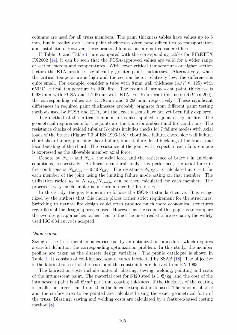
Figure 2. Advanced approach and engineering approach for truss design in fire conditions.
research [10].The paper is organized as follows. Firstly, the two approaches for truss design in fire
conditions considered in this study are described. Then, the cost optimization problem ispresented, including details of structural modelling and design according to the Eurocode.The results of optimization are treated in detail, and finally, the implications of the studyare discussed.
Tubular truss design in fire conditions
Designing trusses for fire safety using intumescent coating involves determining the mem-ber profiles and the thickness of the coating. The required amount of the fire paintdepends on the dimensions of the cross-section. For tubular profiles, the key factor is thewall thickness, i.e. for thicker profiles, less paint is required. Consequently, the minimumcost design is a compromise between reducing the member sizes and the amount of intu-mescent paint. In general, this is not a simple task to be solved relying only on experienceand engineering skills.
In this study, two approaches for truss design in fire conditions are considered. Thefirst approach emulates a conventional engineering process, whereas in the second thecost minimization task is treated more comprehensively. In both approaches, the designis governed by the Eurocodes EN 1993-1-1 [4], EN 1993-1-8 [6] for members and joints inambient conditions, and EN 1993-1-2 [5] for fire design. In this study, the recommendedvalues of all parameters are used, i.e. no national annexes are employed.
The two approaches are schematically illustrated in Fig. 2.
Engineering approach
A typical design procedure is to first design the truss in ambient conditions (room temper-ature), and then to determine the required fire paint thickness for the obtained memberprofiles.
162

The design of the truss in ambient conditions is carried out by applying an optimizationprocedure. This emulates a seasoned engineer, who conventionally tries to find the mosteconomical solution based on experience and judgment.
Advanced approach
It is clear the the engineering approach might lead to relatively thick intumescent coating,because the member profiles are made a small as possible in ambient conditions. In orderto obtain more economical solution, sizing of the member profiles should be coupledwith the determination of the coating thickness. The method of critical temperatureis employed along with manufacturer’s tables for finding the required intumescent paintthickness.
The minimum cost design is determined using a similar optimization procedure as forthe engineering approach. The main difference is that now the cost of the intumescentpaint is included in the cost function, whereas for the engineering approach, the cost ofthe paint is calculated only after the optimization has been terminated.
Cost minimization
Both approaches to truss design in fire conditions rely on optimization. Consequently,the truss design task must be formulated as an optimization problem, which includes thedefinition of design variables, objective function and constraints. This is described inthe following along with details on structural modelling and fire design according to theEurocode.
Structural modelling and design
For evaluating the performance of the truss in elevated temperature, structural analysisin fire conditions must be performed. The truss considered in this study is globallystatically determinate truss of Fig. 1. Due to the structural analysis model used in thisstudy the truss is internally statically indeterminate, but is has been shown that whenthe global support conditions are statically determinate, linear analysis predicts ratherwell the ultimate situation of the truss in fire [1]. This is especially true when dealingwith the stress resultants of the truss.
The resistance of members and joints is verified in the Ultimate Limit State (ULS)in fire. The deflections are handled with pre-cambering, and they are not included inthe analysis. The height of truss is L/10 (L = 36 m is the span) at mid-span and it ismeasured from the bottom of the bottom chord to the top of the top chord. The slope ofthe top chord is 1:20. The truss consists of K-joints, with the gap of 50 mm at each joint.The joints are located evenly at the chords.
The design load in ambient conditions is a uniform load 23.5 kN/m at the top chordand in fire conditions the load is approximated as 0.4 · 23.5 kN/m.
The gaps and profile dimensions induce eccentricities at the joints, which cause sec-ondary bending moments in the members. This is taken into account by introducing rigideccentricity elements at the joints (Fig. 3). An eccentricity element is created between themid-line of the chord and the intersection of the mid-lines of the connecting braces suchthat the element is perpendicular to the chord. The location of the nodes of the eccentric-ity element is calculated from the member profile dimensions, gap size and angles of thebraces. Such structural model based on the accurate geometry is an important feature for
163

Figure 3. Local structural models of K-joints following EN 1993-1-8.
structural analysis and optimization according to the Eurocode, when the joint design isincluded in the procedure, because the details of the joints have an impact on the globalstructural model and therefore on the internal forces of the members.
The chords are modelled as continuous beams and diagonals are hinged at both ends.Euler-Bernoulli beam elements are used for the members and for the local models of thejoints [10]. The buckling length of each member is 0.9 times the system length, which isdefined as in [3], see also [9].
Fire design of members is performed using the method of critical temperatures of EN1993-1-2 and calculating the minimum required intumescent thickness for each member.For compressed members the critical temperature is dependent on the elastic modulustemperature reduction in addition to yield strength reduction. This means that thecritical temperature method is not directly applicable for compressed members, unlesssome iteration is performed. Three iterations for each compressed member proved to besufficient to get the critical temperatures within 1◦C accuracy.
The critical temperature θa,cr (◦C) is calculated as
θa,cr = 39.19 · ln
(1
0.9674µ3.8330
− 1
)+ 482, µ0 ≥ 0.013 (1)
where µ0 is the degree of utilization of the member in fire. When the µ0 of the memberis known the critical temperature of the member can be calculated using Eq. (1). Forsquare tubes the section factor value A/V ≈ 1/t can be used (see EN 1993-1-2). In thisexpression t is the wall thickness of the tube in meters. When the critical temperatureθa,cr and the section factor A/V are known the required intumescent cover thickness isretrieved from the tables of the coating fabricators.
The method for the intumescent design in Finland is moving from nationally ap-proved certified product declarations from the Finnish Constructional Steelwork Asso-ciation (FCSA) to European Technical Approval (ETA) specifications. This affects thetesting method and ultimately the required fire paint thickness. In this study, the ETAapproved intumescent FIRETEX FX2002 is used [14]. This is compared with the olderFIRETEX FX2000 which is approved by FCSA [2] in R30-R60 (valid until June 1st 2016).Different calculation methods are employed for ETA and for FCSA. The ETA gives tablesfor paint thicknesses when critical temperatures are known and FCSA gives formulas fortemperatures when the paint thickness is known. For a straightforward comparison, theintumescent coating thickness tables are calculated also for the FCSA tables using thesame system as for the ETA, see Table 10 and Table 11. Neither FCSA product decla-rations nor ETA specifications give separate rules for profiles in tension, thus values for
164
columns are used for all truss members. The paint thickness tables have values up to 5mm, but in reality over 2 mm paint thicknesses often pose difficulties to transportationand installation. However, these practical limitations are not considered here.
If Table 10 and Table 11 are compared with the corresponding tables for FIRETEXFX2002 [14], it can be seen that the FCSA-approved values are valid for a wider rangeof section factors and temperatures. With lower critical temperatures or higher sectionfactors the ETA produces significantly greater paint thicknesses. Alternatively, whenthe critical temperature is high and the section factor relatively low, the difference isquite small. For example, consider a tube with 8 mm wall thickness (A/V ≈ 125) with650 ◦C critical temperature in R60 fire. The required intumescent paint thickness is0.986 mm with FCSA and 1.208 mm with ETA. For 5 mm wall thickness (A/V ≈ 200),the corresponding values are 1.578 mm and 3.290 mm, respectively. These significantdifferences in required paint thicknesses probably originate from different paint testingmethods used by FCSA and ETA, but the exact reasons have not yet been fully explored.
The method of the critical temperature is also applied to joint design in fire. Thegeometrical requirements for the joints are the same for ambient and fire conditions. Theresistance checks of welded tubular K-joints includes checks for 7 failure modes with axialloads of the braces (Figure 7.3 of EN 1993-1-8): chord face failure, chord side wall failure,chord shear failure, punching shear failure, brace failure, local buckling of the brace, andlocal buckling of the chord. The resistance of the joint with respect to each failure modeis expressed as the allowable member axial force.
Denote by Ni,Ed and Ni,Rd the axial force and the resistance of brace i in ambientconditions, respectively. As linear structural analysis is performed, the axial force infire conditions is Ni,Ed,t0 = 0.40Ni,Ed. The resistance Ni,Rd,t0 is calculated at t = 0 foreach member of the joint using the limiting failure mode acting on that member. Theutilization ratios µ0 = Ni,Ed,t0/Ni,Rd,t0 can be then calculated for each member. Theprocess is very much similar as in normal member fire design.
In this study, the gas temperature follows the ISO-834 standard curve. It is recog-nized by the authors that this choice places rather strict requirement for the structures.Switching to natural fire design could often produce much more economical structuresregardless of the design approach used. However, as the scope of this paper is to comparethe two design approaches rather than to find the most realistic fire scenario, the widelyused ISO-834 curve is adopted.
Optimization
Sizing of the truss members is carried out by an optimization procedure, which requiresa careful definition the corresponding optimization problem. In this study, the memberprofiles are taken as the discrete design variables. The profile catalogue is shown inTable 1. It consists of cold-formed square tubes fabricated by SSAB [18]. The objectiveis the fabrication cost of the truss, and the constraints are derived from EN 1993.
The fabrication costs include material, blasting, sawing, welding, painting and costsof the intumescent paint. The material cost for S420 steel is 1 e/kg, and the cost of theintumescent paint is 40 e/m2 per 1 mm coating thickness. If the thickness of the coatingis smaller or larger than 1 mm then the linear extrapolation is used. The amount of steeland the surface area to be painted are calculated using the exact geometrical form ofthe truss. Blasting, sawing and welding costs are calculated by a featured-based costingmethod [8].
165

Table 1. Catalogue of square hollow sections. The tube dimensions are given in form h × t, where h isthe outer dimension (width or height) in millimeters and t is the wall thickness in millimeters.
25x3 70x4 100x5 140x6 180x830x3 70x5 100x6 140x8 180x1040x3 80x3 100x8 150x5 200x840x4 80x4 110x4 150x6 200x1050x3 80x5 110x5 150x8 200x12.550x4 80x6 120x4 150x10 250x650x5 90x3 120x5 150x12.5 250x860x3 90x4 120x6 160x6 250x1060x4 90x5 120x8 160x8 250x12.560x5 90x6 120x10 160x10 300x1070x3 100x4 140x5 180x6 300x12.5
The numerical values of the different cost factors are very much dependent on thecountry, contractor and other issues. However, in order to compare different solutionsthese values must be estimated. In this study the costs mentioned above have beenobtained from discussions with contractors in Finland. Transport and erection costs onsite are not taken into account in this analysis, because they do not play an importantrole in this comparison. In the engineering approach the cost of the intumescent paint isnot included in the objective function. The cost of fire protection is added to the otherfabrication costs of the truss after optimization.
The constraints are derived from the Eurocodes. For members this implies axial force,shear force and bending moment resistances in ambient conditions. Flexural buckling andbeam-column behaviour of compression members are taken into account using EN 1993-1-1, Method B. The corresponding resistances are also verified in fire conditions using EN1993-1-2.
The K-joints (not at support and at the ridge) are checked in ambient conditions ac-cording to EN 1993-1-8 and in fire by EN 1993-1-2. The joint constraints include the jointresistance checks and the geometrical conditions which define the range of applicability ofthe resistance rules. Full strength welds are used at the joints. This implies that for S420members, the weld size is 1.4t where t is the wall thickness of the connected brace. In firecondition the resistance of the welds is not considered. The details of the optimizationproblem can be found in [19].
Sizing optimization is performed using the metaheuristic Particle Swarm Optimization(PSO) method. PSO cannot guarantee the optimality of the solution, but with sufficientlylarge swarm size and using proper parameters, satisfactory results can be obtained. Thedetails of PSO can be found in [12] and the applied constraint handling mechanism isdescribed in [16]. The algorithm is run with the following key parameters: populationsize 250, iterations 120, number of runs 40.
In the engineering approach the truss is optimized in ambient conditions. To excludeimpractically thin profiles for fire design, the minimum wall thickness of 5 mm is pre-scribed. This limitation is not needed in advanced approach due to the more holisticnature of the method.
After optimization, the required intumescent thicknesses are calculated using the crit-ical temperatures for the members and for the joints. If the critical temperature andsection factor combination is outside the range of the intumescent paint, the thickness
166

Figure 4. Member labels.
Table 2. Results of optimization. Best found member profiles. The member labels correspond to Fig. 4.TC and BC refer to top and bottom chords, respectively.
Method Engineering Advanced
Paint ETA FCSA ETA FCSA
Fire R30 R60 R30 R60 R30 R60 R30 R60
TC 180x10 180x10 180x10 180x10 180x10 180x10 180x10 180x10BC 120x8 120x8 120x8 120x8 120x8 150x10 120x8 120x10B1 50x5 50x5 50x5 50x5 50x3 80x6 80x4 50x4B2 70x5 70x5 70x5 70x5 70x3 80x6 70x4 80x4B3 90x5 90x5 90x5 90x5 110x4 120x6 90x5 80x6B4 70x5 70x5 70x5 70x5 80x3 100x6 70x4 70x5B5 100x5 100x6 100x5 100x5 100x5 150x6 100x5 100x6B6 70x5 70x5 70x5 70x5 70x4 100x6 70x4 80x6B7 120x5 120x6 120x5 120x5 120x5 140x8 120x5 120x6B8 90x5 90x5 90x5 90x5 90x4 120x6 90x6 80x6
of the member is increased for the next possible. Altogether four different intumescentcoating thicknesses are allowed in the truss: one for the top chord, one for the bottomchord and two for the braces. This reflects the fact that at employing individual coatingthicknesses at the workshop is time-consuming and prone to errors. In the engineeringapproach the grouping of the braces is done after the intumescent coating thickness isdefined to all members separately. In the advanced approach this sorting is done duringthe optimization.
Results
The member profiles obtained by PSO are listed in Table 2 for different fire cases and forthe two approaches described above. As can be expected, the profiles obtained by theengineering approach are nearly identical in all four cases. Only the braces B5 and B7needed to be changed in R60 fire using ETA. In the advanced approach the member sizesvary considerably depending on the case. Only the top chord profile remains constantamong the different cases.
The fire paint thicknesses for the optimized designs are shown in Table 3. For R30,the paint thicknesses are nearly identical for both approaches and ETA and FCSA tables.On the other hand, for R60, substantial differences can be observed. Using the advancedapproach clearly leads to thinner coating, especially when ETA approval is adopted. Forexample, using the ETA approval, the engineering approach leads to paint thicknessof 1.949 mm for the bottom chord, whereas only 0.506 mm layer is required when theadvanced approach is utilized. Similar ratio applies for the braces as well, but for the
167

Table 3. Fire paint thicknesses (mm).
Method Engineering Advanced
Paint ETA FCSA ETA FCSA
Fire R30 R60 R30 R60 R30 R60 R30 R60
Top Chord 0.462 0.980 0.325 0.885 0.462 0.987 0.325 0.885Bottom Chord 0.462 1.949 0.427 1.166 0.462 0.506 0.427 0.879
B1 0.462 2.846 0.500 1.494 0.462 1.062 0.435 1.091B2 0.462 2.846 0.500 1.494 0.462 1.062 0.435 1.091B3 0.462 3.813 0.742 1.968 0.462 0.768 0.742 1.584B4 0.462 2.846 0.500 1.494 0.462 0.768 0.435 1.091B5 0.522 3.813 0.742 1.968 0.523 0.768 0.742 1.584B6 0.522 2.846 0.500 1.494 0.523 0.768 0.742 1.091B7 0.522 3.813 0.742 1.968 0.523 1.062 0.742 1.584B8 0.522 3.813 0.742 1.968 0.523 1.062 0.435 1.584
Table 4. Minimum costs, the corresponding weights and costs distributions.
Method Engineering Advanced
Paint ETA FCSA ETA FCSA
Fire R30 R60 R30 R60 R30 R60 R30 R60
Weight (kg) 1651 1670 1651 1651 1607 2105 1650 1764Cost (e) 2569 4273 2543 3411 2499 3746 2534 3327
Material 1651 1670 1651 1651 1607 2105 1650 1764Welding 146 165 146 146 108 297 139 176Sawing 97 98 97 97 97 103 97 97Blasting 22 22 22 22 22 22 22 22Painting 128 127 128 128 130 147 130 127
Fire Paint 525 2191 499 1367 535 1071 496 1140
top chord, the paint thickness is virtually identical for both approaches. When the paintthickness is determined according to FCSA, the difference between the two approachesis smaller. The engineering approach leads to 25–36% greater paint thickness, except forthe top chord.
The costs and weights of the obtained designs are given in Table 4. The advancedapproach leads to slightly more economical designs with ETA in R30 and FCSA in R60.There is practically no difference in cost using FCSA in R30. However, in R60 with ETA,the advanced approach gives 12 % from the solution obtained by the engineering approach.Note that in this case, the weight of the more economical solution is 26% greater thanthe weight of the less economical design.
The cost distributions of the solutions, shown in Table 4, illustrate the fact that inR60 the cost of the intumescent coating can be as great as (or greater than) the cost ofsteel when engineering approach is employed. Using the advanced approach the cost ofthe fire paint is always smaller than the material cost. Note that with the adopted unitcosts, the cost of fire paint is greater than the other fabrication costs combined.
168

Table 5. Utilities of members with respect to the resistances.
Method Engineering Advanced
Paint ETA FCSA ETA FCSA
Fire R30 R60 R30 R60 R30 R60 R30 R60
B1 0.01 0.01 0.01 0.01 0.01 0 0 0.01B2 0.01 0.01 0.01 0.01 0 0.01 0.01 0.01B3 0.60 0.60 0.60 0.60 0.43 0.25 0.60 0.73B4 0.26 0.26 0.26 0.26 0.36 0.15 0.32 0.26B5 0.89 0.77 0.89 0.89 0.89 0.31 0.89 0.77B6 0.58 0.58 0.58 0.58 0.70 0.33 0.70 0.42B7 0.93 0.80 0.93 0.93 0.93 0.46 0.93 0.80B8 0.71 0.71 0.71 0.71 0.86 0.44 0.60 0.69
TC1 0.85 0.85 0.85 0.85 0.85 0.85 0.85 0.85TC2 0.82 0.81 0.82 0.82 0.81 0.82 0.82 0.81TC3 0.64 0.63 0.64 0.64 0.63 0.63 0.63 0.63TC4 0.41 0.41 0.41 0.41 0.41 0.41 0.41 0.41BC1 0.80 0.80 0.80 0.80 0.79 0.52 0.80 0.66BC2 0.87 0.87 0.87 0.87 0.89 0.56 0.87 0.72BC3 0.72 0.72 0.72 0.72 0.73 0.49 0.72 0.61BC4 0.99 0.99 0.99 0.99 0.99 0.59 0.99 0.80
In order to evaluate the performance of PSO in this problem the utilization ratios ofmembers and joints with respect to the resistances are given in Table 5 and Table 6. The”utilities” with respect to the geometrical properties of the joints are given in Table 7, andthe maximum utilization ratios for all members, including member and joint resistancesand the geometrical ”utilities” are given in Table 8. It can be seen, that very highutilization ratios (values near 1.00) are obtained in all cases, which implies excellentperformance of the designs.
The sensitivity of the solutions with respect to the initial cost data is examined byre-optimizing the structures using the steel material cost 0.8 e/kg instead of 1.0 e/kg.The obtained costs and the corresponding weights are given in Table 9.
Table 6. Utilities of joints with respect to the resistance.
Method Engineering Advanced
Paint ETA FCSA ETA FCSA
Fire R30 R60 R30 R60 R30 R60 R30 R60
B1-BC-B2 0.88 0.88 0.88 0.88 0.88 0.57 0.88 0.73B2-TC-B3 0.46 0.46 0.46 0.46 0.46 0.46 0.46 0.46B3-BC-B4 0.89 0.89 0.89 0.89 0.89 0.57 0.89 0.74B4-TC-B5 0.58 0.59 0.58 0.58 0.53 0.44 0.58 0.6B5-BC-B6 0.82 0.82 0.82 0.82 0.82 0.52 0.82 0.66B6-TC-B7 0.81 0.81 0.81 0.81 0.81 0.58 0.82 0.75B7-BC-B8 0.95 0.95 0.95 0.95 0.95 0.5 0.95 0.79
169

Table 7. ”Utilities” of geometrical constraints at joints.
Method Engineering Advanced
Paint ETA FCSA ETA FCSA
Fire R30 R60 R30 R60 R30 R60 R30 R60
B1-BC-B2 0.84 0.84 0.84 0.84 0.84 0.70 0.74 0.84B2-TC-B3 1.00 1.00 1.00 1.00 0.90 0.90 1.00 1.00B3-BC-B4 0.83 0.83 0.83 0.83 0.92 0.83 0.83 0.74B4-TC-B5 0.95 0.95 0.95 0.95 0.90 0.83 0.95 0.95B5-BC-B6 0.95 0.95 0.95 0.95 0.95 1.00 0.95 0.90B6-TC-B7 0.90 0.90 0.90 0.90 0.90 0.78 0.90 0.80B7-BC-B8 1.00 1.00 1.00 1.00 1.00 0.93 1.00 1.00
Table 8. Combined utilities.
Method Engineering Advanced
Paint ETA FCSA ETA FCSA
Fire R30 R60 R30 R60 R30 R60 R30 R60
B1 0.88 0.88 0.88 0.88 0.88 0.70 0.88 0.84B2 1.00 1.00 1.00 1.00 0.90 0.90 1.00 1.00B3 1.00 1.00 1.00 1.00 0.92 0.90 1.00 1.00B4 0.95 0.95 0.95 0.95 0.92 0.83 0.95 0.95B5 0.95 0.95 0.95 0.95 0.95 1.00 0.95 0.95B6 0.95 0.95 0.95 0.95 0.95 1.00 0.95 0.90B7 1.00 1.00 1.00 1.00 1.00 0.93 1.00 1.00B8 1.00 1.00 1.00 1.00 1.00 0.93 1.00 1.00
TC1 1.00 1.00 1.00 1.00 0.90 0.90 1.00 1.00TC2 1.00 1.00 1.00 1.00 0.90 0.90 1.00 1.00TC3 0.95 0.95 0.95 0.95 0.90 0.83 0.95 0.95TC4 0.90 0.90 0.90 0.90 0.90 0.78 0.90 0.80BC1 0.88 0.88 0.88 0.88 0.88 0.70 0.88 0.84BC2 0.89 0.89 0.89 0.89 0.92 0.83 0.89 0.84BC3 0.95 0.95 0.95 0.95 0.95 1.00 0.95 0.90BC4 1.00 1.00 1.00 1.00 1.00 0.93 1.00 1.00
As the material unit cost is decreased, the advanced approach leads to greater savingsthan in the first scenario, where the unit cost of steel was 1.0e/kg. Using ETA in R60,the advanced approach gives 23 % more economical design than the engineering approach.For the other cases, from 4 % to 8 % savings can be achieved by the advanced approach.
Conclusions
The findings of the present study indicate that the proposed ”advanced approach” shouldbe employed in fire design of tubular trusses in all cases. Especially when the fire resistancerequirement is high traditional method of finding the least weight solution does not seemto produce the most economical solution. The single drawback of the advanced approach
170

Table 9. Costs and weights of optimal cases using the steel material cost 0.8 e/kg.
Method Engineering Advanced
Paint ETA FCSA ETA FCSA
Fire R30 R60 R30 R60 R30 R60 R30 R60
Cost (e) 2317 4303 2292 3286 2197 3315 2210 3020Weight (kg) 1630 1640 1630 1630 1619 1977 1643 1824
is that it requires unit costs for steel, intumescent paint and other fabrication phases. Inorder to provide the designer with the best possible tools for finding the most economicalstructures, the authors recommend that the workshops and steel producers make thisdata available. This can be done, for example, in a closed design software, that enablescost optimization but does not reveal all sensitive cost data.
In this study the particle swarm optimization method was employed, but the auto-mated member sizing can be performed by other means as well, including sophisticatedmathematical programming methods, and ad hoc engineering rules. The most importantfeature of advanced approach is the combined sizing and intumescent paint thickness de-termination which are done simultaneously in order to find the most economical designs.
Finally, it should be noted that it is the experience of the authors that the discreteoptimization problem resulting from detailed structural modelling and constraints derivedfrom the Eurocode is very difficult to solve, and possibly a combination of heuristicmethods and mathematical programming algorithms leads to a suitable solution strategy.
Acknowledgements
Ruukki Construction Oy and FIMECC/MANU/Digimap are acknowledged for the finan-cial support for this study.
References
[1] J.A. Diez Albero, T. Tiainen, K. Mela, and M. Heinisuo. Structural analysis of tubu-lar trusses in fire. In E. Batista, P. Vellasco, and L. Lima, editors, Tubular StructuresXV, Rio de Janeiro, Brazil, May 2015. Proceedings of the 15th international sympo-sium on tubular structures.
[2] Finnish Constructional Steel Association. Varmennettu Kayttoseloste TRY-107-2011: FIRETEX FX2000 -palosuojamaali putki- ja I-profiilien palosuojaukseen.Finnish Constructional Steel Association, 2011. In Finnish.
[3] H. Boel. Buckling length factors of hollow section members in lattice girders. Master’sthesis, Eindhoven University of Technology, 2010.
[4] EN 1993–1–1. Eurocode 3: Design of Steel Structures. Part 1-1: General rules andrules for buildings. CEN, 2005.
[5] EN 1993–1–2. Eurocode 3: Design of Steel Structures. Part 1-2: General rules –Structural fire design. CEN, 2005.
171

[6] EN 1993–1–8. Eurocode 3: Design of Steel Structures. Part 1-8: Design of joints.CEN, 2005.
[7] J. Farkas and K. Jarmai, editors. Optimum Design of Steel Structures. Springer,2013.
[8] J. Haapio. Feature-Based Costing Method for Skeletal Steel Structures Based on theProcess Approach. PhD thesis, Tampere University of Technology, 2012.
[9] M. Heinisuo and A. Haakana. Buckling of members of welded tubular truss. InMarkku Heinisuo and Jari Makinen, editors, Proceedings of The 13th Nordic SteelConstruction Conference (NSCC-2015), pages 23–25, Tampere, Finland, sep 2015.
[10] J. Jalkanen. Tubular Truss Optimization Using Heuristic Algorithms. PhD thesis,Tampere University of Technology, 2007.
[11] K. Jarmai and J. Farkas. Cost calculation and optimisation of welded steel structures.Journal of Constructional Steel Research, 50:115–135, 1999. doi:10.1016/S0143-974X(98)00241-7.
[12] J. Kennedy and R. Eberhart. Particle swarm optimization. In IEEE InternationalConference on Neural Networks, pages 1942–1948, 1995.
[13] U. Klansek and S. Kravanja. Cost estimation, optimization and competitivenessof different composite floor systems–part 1: Self-manufacturing cost estimation ofcomposite and steel structures. Journal of Constructional Steel Research, 62:434–448, 2006. doi:10.1016/j.jcsr.2005.08.005.
[14] Warrington Certification LTD. European technical approval ETA-12/0049: FIRE-TEX FX2002 and FIRETEX FX1002. EOTA, Warrington, UK, 2013.
[15] L. Pavlovcic, A. Krajnc, and D. Beg. Cost function analysis in the structural opti-mization of steel frames. Structural and Multidisciplinary Optimization, 28:286–295,2004. doi:10.1007/s00158-004-0430-z.
[16] G.T. Pulido and C.A.C. Coello. A constraint-handling mechanism for particle swarmoptimization. In Congress on Evolutionary Computation, volume 2, pages 1396 –1403, june 2004. doi:10.1109/CEC.2004.1331060.
[17] K. C. Sarma and H. Adeli. Cost optimization of steel structures. Engineering Opti-mization, 32:777–802, 2000. doi:10.1080/03052150008941321.
[18] SSAB. Structural Hollow Section, 2016. Dimensions and cross-sectional properties.
[19] T. Tiainen, K. Mela, and M. Heinisuo. High strength steel in tubular trusses. Struc-tures and Buildings, 2016. Submitted.
[20] K.B. Watson, S. Dallas, N. Van der Kreek, and T. Main. Costing of steelwork fromfeasibility through to completion. Journal of Australian Steel Construction, 30(2):9,1996.
172

Timo JokinenPalotekninen Insinooritoimisto Markku Kauriala OyHermiankatu 6-8 DFI-33720 [email protected]
Kristo Mela, Teemu Tiainen, Markku HeinisuoTampere University of TechnologyDepartment of Civil EngineeringP.O.Box 600FI-33101 [email protected] [email protected]
Appendix: FIRETEX FX2000 coating thickness tables
The coating thickness values are calculated using procedure described in [2]. The unitsystem in the Tables is: Intumescent thickness [mm], Critical temperature T [◦C], Sectionfactor A/V [1/m].
173

Table 10. FIRETEX FX2000, RHS, R30.
A/VT
350 400 450 500 550 600 650 700 750 800 850
70 0.759 0.558 0.431 0.346 0.300 0.300 0.300 0.300 0.300 0.300 0.30075 0.813 0.598 0.462 0.371 0.305 0.300 0.300 0.300 0.300 0.300 0.30080 0.867 0.638 0.493 0.396 0.326 0.300 0.300 0.300 0.300 0.300 0.30085 0.921 0.678 0.523 0.421 0.346 0.300 0.300 0.300 0.300 0.300 0.30090 0.976 0.718 0.554 0.445 0.366 0.304 0.300 0.300 0.300 0.300 0.30095 1.030 0.757 0.585 0.470 0.387 0.321 0.300 0.300 0.300 0.300 0.300100 1.084 0.797 0.616 0.495 0.407 0.338 0.300 0.300 0.300 0.300 0.300105 1.138 0.837 0.647 0.520 0.427 0.354 0.300 0.300 0.300 0.300 0.300110 1.192 0.877 0.677 0.544 0.448 0.371 0.307 0.300 0.300 0.300 0.300115 1.247 0.917 0.708 0.569 0.468 0.388 0.321 0.300 0.300 0.300 0.300120 1.301 0.957 0.739 0.594 0.489 0.405 0.335 0.300 0.300 0.300 0.300125 1.355 0.997 0.770 0.619 0.509 0.422 0.349 0.300 0.300 0.300 0.300130 1.409 1.037 0.801 0.643 0.529 0.439 0.363 0.300 0.300 0.300 0.300135 1.463 1.076 0.831 0.668 0.550 0.456 0.376 0.306 0.300 0.300 0.300140 1.518 1.116 0.862 0.693 0.570 0.473 0.390 0.318 0.300 0.300 0.300145 1.572 1.156 0.893 0.717 0.590 0.489 0.404 0.329 0.300 0.300 0.300150 1.626 1.196 0.924 0.742 0.611 0.506 0.418 0.341 0.300 0.300 0.300155 1.680 1.236 0.955 0.767 0.631 0.523 0.432 0.352 0.300 0.300 0.300160 1.734 1.276 0.985 0.792 0.651 0.540 0.446 0.363 0.300 0.300 0.300165 1.789 1.316 1.016 0.816 0.672 0.557 0.460 0.375 0.300 0.300 0.300170 1.843 1.355 1.047 0.841 0.692 0.574 0.474 0.386 0.300 0.300 0.300175 1.897 1.395 1.078 0.866 0.712 0.591 0.488 0.397 0.309 0.300 0.300180 1.951 1.435 1.109 0.891 0.733 0.608 0.502 0.409 0.318 0.300 0.300185 2.005 1.475 1.139 0.915 0.753 0.624 0.516 0.420 0.327 0.300 0.300190 2.060 1.515 1.170 0.940 0.774 0.641 0.530 0.431 0.336 0.300 0.300195 2.114 1.555 1.201 0.965 0.794 0.658 0.544 0.443 0.345 0.300 0.300200 2.168 1.595 1.232 0.990 0.814 0.675 0.558 0.454 0.353 0.300 0.300205 2.222 1.635 1.263 1.014 0.835 0.692 0.572 0.465 0.362 0.300 0.300210 2.276 1.674 1.293 1.039 0.855 0.709 0.586 0.477 0.371 0.300 0.300215 2.331 1.714 1.324 1.064 0.875 0.726 0.600 0.488 0.380 0.300 0.300220 2.385 1.754 1.355 1.089 0.896 0.743 0.614 0.499 0.389 0.300 0.300225 2.439 1.794 1.386 1.113 0.916 0.759 0.627 0.511 0.398 0.300 0.300230 2.493 1.834 1.417 1.138 0.936 0.776 0.641 0.522 0.406 0.300 0.300235 2.547 1.874 1.447 1.163 0.957 0.793 0.655 0.533 0.415 0.300 0.300240 2.602 1.914 1.478 1.188 0.977 0.810 0.669 0.545 0.424 0.300 0.300245 2.656 1.953 1.509 1.212 0.997 0.827 0.683 0.556 0.433 0.300 0.300250 2.710 1.993 1.540 1.237 1.018 0.844 0.697 0.568 0.442 0.300 0.300255 2.764 2.033 1.570 1.262 1.038 0.861 0.711 0.579 0.451 0.300 0.300260 2.818 2.073 1.601 1.286 1.059 0.878 0.725 0.590 0.460 0.306 0.300265 2.873 2.113 1.632 1.311 1.079 0.894 0.739 0.602 0.468 0.312 0.300270 2.927 2.153 1.663 1.336 1.099 0.911 0.753 0.613 0.477 0.318 0.300275 2.981 2.193 1.694 1.361 1.120 0.928 0.767 0.624 0.486 0.323 0.300280 2.233 1.724 1.385 1.140 0.945 0.781 0.636 0.495 0.329 0.300285 2.272 1.755 1.410 1.160 0.962 0.795 0.647 0.504 0.335 0.300290 2.312 1.786 1.435 1.181 0.979 0.809 0.658 0.513 0.341 0.300295 2.352 1.817 1.460 1.201 0.996 0.823 0.670 0.521 0.347 0.300300 2.392 1.848 1.484 1.221 1.013 0.837 0.681 0.530 0.353 0.300
174

Table 11. FIRETEX FX2000, RHS, R60.
A/VT
350 400 450 500 550 600 650 700 750 800 850
70 1.465 1.187 0.993 0.847 0.730 0.634 0.552 0.479 0.409 0.339 0.30075 1.569 1.272 1.064 0.908 0.782 0.679 0.592 0.513 0.438 0.363 0.30080 1.674 1.357 1.135 0.968 0.835 0.725 0.631 0.547 0.467 0.387 0.30585 1.778 1.442 1.206 1.029 0.887 0.770 0.671 0.581 0.496 0.412 0.32490 1.883 1.526 1.277 1.089 0.939 0.815 0.710 0.616 0.526 0.436 0.34395 1.988 1.611 1.348 1.150 0.991 0.861 0.750 0.650 0.555 0.460 0.362100 2.092 1.696 1.419 1.210 1.043 0.906 0.789 0.684 0.584 0.484 0.381105 2.197 1.781 1.490 1.271 1.095 0.951 0.829 0.718 0.613 0.509 0.400110 2.302 1.866 1.561 1.331 1.148 0.997 0.868 0.753 0.642 0.533 0.419115 2.406 1.950 1.632 1.392 1.200 1.042 0.907 0.787 0.672 0.557 0.439120 2.511 2.035 1.703 1.452 1.252 1.087 0.947 0.821 0.701 0.581 0.458125 2.615 2.120 1.774 1.513 1.304 1.132 0.986 0.855 0.730 0.605 0.477130 2.720 2.205 1.845 1.573 1.356 1.178 1.026 0.889 0.759 0.630 0.496135 2.825 2.290 1.916 1.634 1.408 1.223 1.065 0.924 0.788 0.654 0.515140 2.929 2.374 1.987 1.694 1.461 1.268 1.105 0.958 0.818 0.678 0.534145 2.459 2.058 1.755 1.513 1.314 1.144 0.992 0.847 0.702 0.553150 2.544 2.129 1.815 1.565 1.359 1.184 1.026 0.876 0.726 0.572155 2.629 2.200 1.876 1.617 1.404 1.223 1.060 0.905 0.751 0.591160 2.713 2.271 1.936 1.669 1.450 1.263 1.095 0.934 0.775 0.610165 2.798 2.342 1.997 1.721 1.495 1.302 1.129 0.964 0.799 0.629170 2.883 2.413 2.057 1.774 1.540 1.341 1.163 0.993 0.823 0.648175 2.968 2.484 2.118 1.826 1.585 1.381 1.197 1.022 0.848 0.667180 2.555 2.178 1.878 1.631 1.420 1.231 1.051 0.872 0.686185 2.626 2.239 1.930 1.676 1.460 1.266 1.081 0.896 0.705190 2.697 2.299 1.982 1.721 1.499 1.300 1.110 0.920 0.724195 2.768 2.360 2.034 1.767 1.539 1.334 1.139 0.944 0.744200 2.839 2.420 2.087 1.812 1.578 1.368 1.168 0.969 0.763205 2.910 2.481 2.139 1.857 1.618 1.402 1.197 0.993 0.782210 2.981 2.541 2.191 1.903 1.657 1.437 1.227 1.017 0.801215 2.602 2.243 1.948 1.697 1.471 1.256 1.041 0.820220 2.662 2.295 1.993 1.736 1.505 1.285 1.065 0.839225 2.723 2.347 2.038 1.775 1.539 1.314 1.090 0.858230 2.784 2.399 2.084 1.815 1.573 1.343 1.114 0.877235 2.844 2.452 2.129 1.854 1.608 1.373 1.138 0.896240 2.905 2.504 2.174 1.894 1.642 1.402 1.162 0.915245 2.965 2.556 2.220 1.933 1.676 1.431 1.187 0.934250 2.608 2.265 1.973 1.710 1.460 1.211 0.953255 2.660 2.310 2.012 1.744 1.489 1.235 0.972260 2.712 2.356 2.052 1.779 1.519 1.259 0.991265 2.765 2.401 2.091 1.813 1.548 1.283 1.010270 2.817 2.446 2.131 1.847 1.577 1.308 1.029275 2.869 2.491 2.170 1.881 1.606 1.332 1.049280 2.921 2.537 2.209 1.915 1.635 1.356 1.068285 2.973 2.582 2.249 1.950 1.665 1.380 1.087290 2.627 2.288 1.984 1.694 1.404 1.106295 2.673 2.328 2.018 1.723 1.429 1.125300 2.718 2.367 2.052 1.752 1.453 1.144
175