Optimization of Transonic Axial Compressor Blades
31
Marcus Lejon* Niklas Andersson* Lars Ellbrant** Hans Mårtensson** Optimization of Transonic Axial Compressor Blades * Chalmers University of Technology ** GKN Aerospace
Transcript of Optimization of Transonic Axial Compressor Blades

Marcus Lejon*
Niklas Andersson*
Lars Ellbrant**
Hans Mårtensson**
Optimization of Transonic Axial Compressor Blades
* Chalmers University of Technology ** GKN Aerospace

11/2/2016 Chalmers 2
• The Axial Compressor
• Project Overview
• The Optimization Process
• The Tip Clearance
• Summary
• Work in-progress
Outline

11/2/2016 Chalmers 3
• The Axial Compressor
• Project Overview
• The Optimization Process
• The Tip Clearance
• Summary
• Work in-progress
Outline

11/2/2016 Chalmers 4
The Axial Compressor
Figure from rolls-royce.com
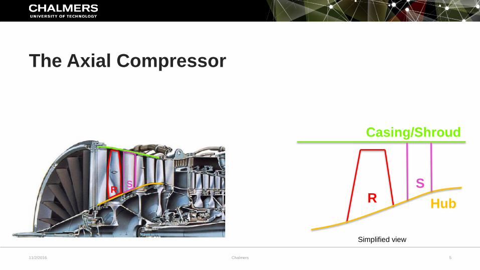
• Consist of rotating and stationary blade rows
• Does work to the flow, increase density and pressure
Figure from rolls-royce.com
11/2/2016 Chalmers 5
The Axial Compressor
R R
Casing/Shroud
Simplified view
Hub
S S
11/2/2016 Chalmers 6
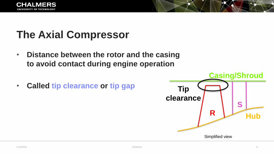
The Axial Compressor
• Distance between the rotor and the casing
to avoid contact during engine operation
• Called tip clearance or tip gap
Casing/Shroud
Simplified view
Hub R S
Tip
clearance
11/2/2016 Chalmers 7
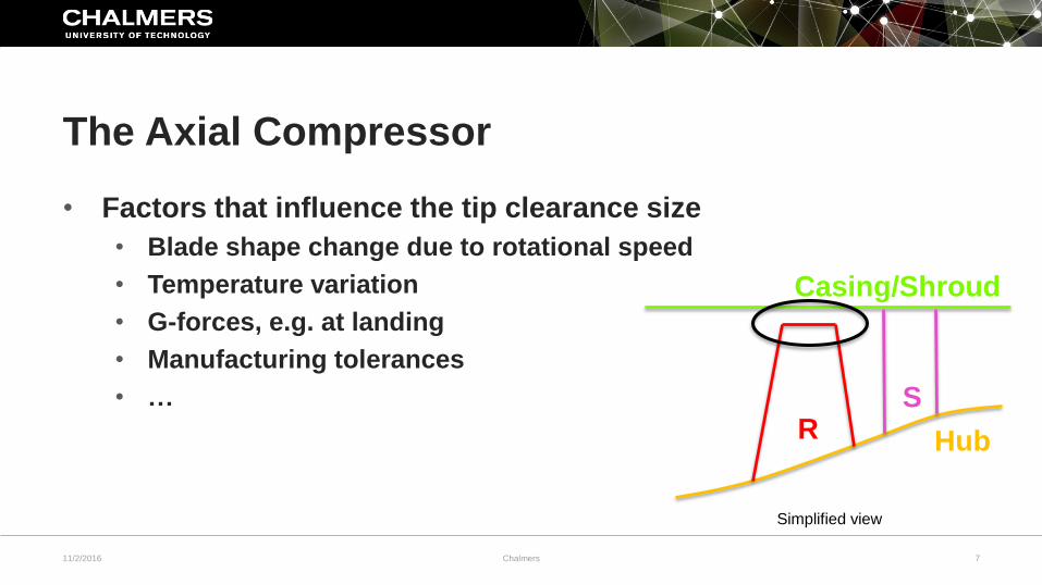
The Axial Compressor
• Factors that influence the tip clearance size
• Blade shape change due to rotational speed
• Temperature variation
• G-forces, e.g. at landing
• Manufacturing tolerances
• …
Casing/Shroud
Simplified view
Hub R S
11/2/2016 Chalmers 8
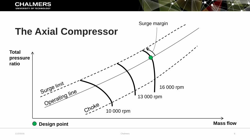
The Axial Compressor
Total
pressure
ratio
Mass flow
16 000 rpm
10 000 rpm
Design point
Surge margin
13 000 rpm

11/2/2016 Chalmers 9
• The Axial Compressor
• Project Overview
• The Optimization Process
• The Tip Clearance
• Summary
• Work in-progress
Outline

11/2/2016 Chalmers 10
• Improve robustness of compressor blades
• Optimization has been used as a tool to evaluate how surface
degradation and the tip clearance can be considered in the
design phase
• Industry partner: GKN Aerospace
Project Overview

11/2/2016 Chalmers 11
• The Axial Compressor
• Project Overview
• The Optimization Process
• The Tip Clearance
• Summary
• Work in-progress
Outline

11/2/2016 Chalmers 12
• Genetic algorithm, mimics evolution in nature
• Design variables are represented by a number of ones and zeros (genes)
• decoded to return the variable value
• Improving designs generation by generation
• Tournament selection
• individuals compete to pass along their genes to the next generation
• Mutation, 1 → 0 or 0 → 1
The Optimization Process

11/2/2016 Chalmers 13
The Optimization Process

11/2/2016 Chalmers 14
• The Axial Compressor
• Project Overview
• The Optimization Process
• The Tip Clearance
• Summary
• Work in-progress
Outline

11/2/2016 Chalmers 15
• Can be the source of a large part of the total losses
• Blade height decrease further back in the compressor
• Tip clearance size relative to the blade height increase
• Limit the stable operating range of a compressor rotor
The Tip Clearance
11/2/2016 Chalmers 16
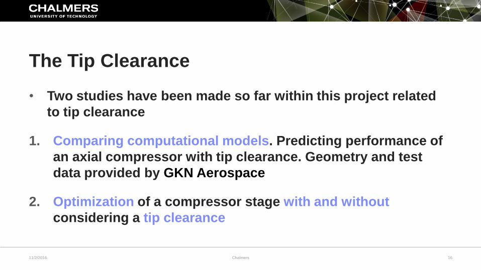
• Two studies have been made so far within this project related
to tip clearance
1. Comparing computational models. Predicting performance of
an axial compressor with tip clearance. Geometry and test
data provided by GKN Aerospace
2. Optimization of a compressor stage with and without
considering a tip clearance
The Tip Clearance
11/2/2016 Chalmers 17
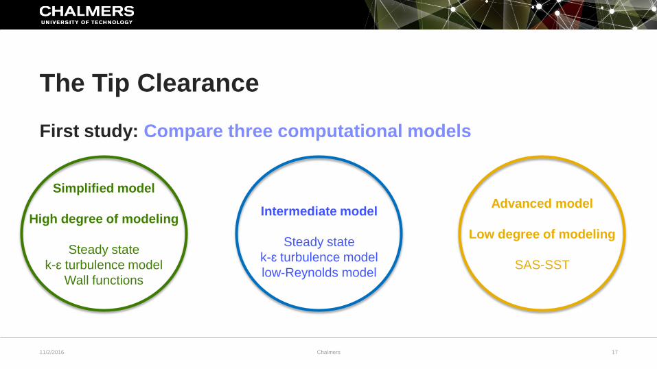
First study: Compare three computational models
The Tip Clearance
Simplified model
High degree of modeling
Steady state
k-ɛ turbulence model
Wall functions
Intermediate model
Steady state
k-ɛ turbulence model
low-Reynolds model
Advanced model
Low degree of modeling
SAS-SST
11/2/2016 Chalmers 18
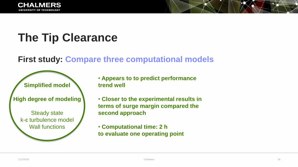
First study: Compare three computational models
The Tip Clearance
Simplified model
High degree of modeling
Steady state
k-ɛ turbulence model
Wall functions
• Appears to to predict performance
trend well
• Closer to the experimental results in
terms of surge margin compared the
second approach
• Computational time: 2 h
to evaluate one operating point
11/2/2016 Chalmers 19
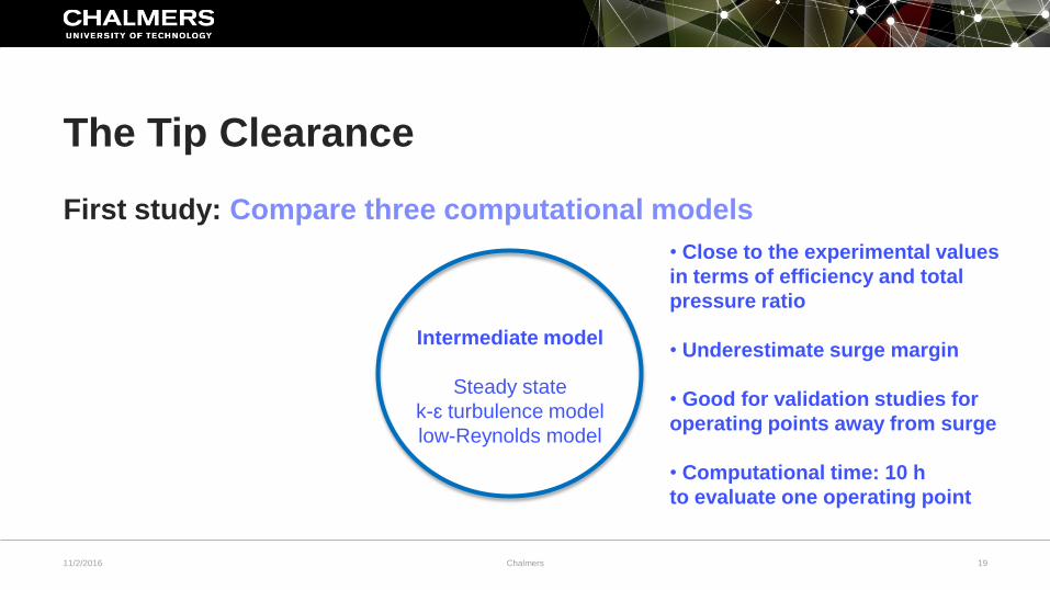
First study: Compare three computational models
The Tip Clearance
Intermediate model
Steady state
k-ɛ turbulence model
low-Reynolds model
• Close to the experimental values
in terms of efficiency and total
pressure ratio
• Underestimate surge margin
• Good for validation studies for
operating points away from surge
• Computational time: 10 h
to evaluate one operating point
11/2/2016 Chalmers 20
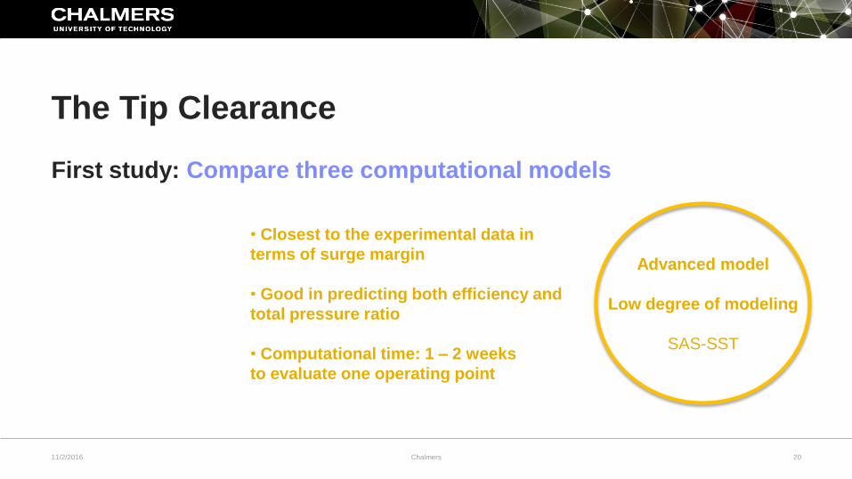
First study: Compare three computational models
The Tip Clearance
Advanced model
Low degree of modeling
SAS-SST
• Closest to the experimental data in
terms of surge margin
• Good in predicting both efficiency and
total pressure ratio
• Computational time: 1 – 2 weeks
to evaluate one operating point
11/2/2016 Chalmers 21
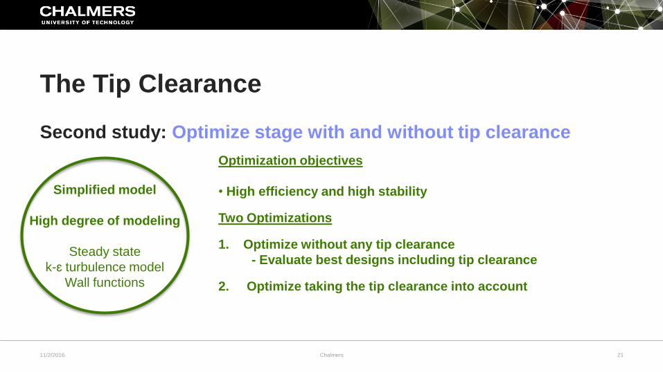
Second study: Optimize stage with and without tip clearance
The Tip Clearance
Simplified model
High degree of modeling
Steady state
k-ɛ turbulence model
Wall functions
Optimization objectives
• High efficiency and high stability
Two Optimizations
1. Optimize without any tip clearance
- Evaluate best designs including tip clearance
2. Optimize taking the tip clearance into account
11/2/2016 Chalmers 22
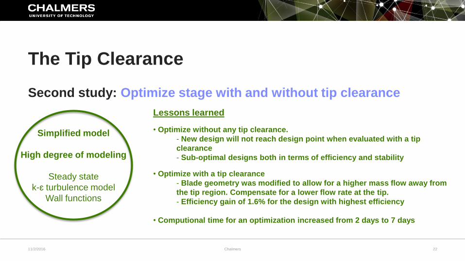
Second study: Optimize stage with and without tip clearance
The Tip Clearance
Simplified model
High degree of modeling
Steady state
k-ɛ turbulence model
Wall functions
Lessons learned
• Optimize without any tip clearance.
- New design will not reach design point when evaluated with a tip
clearance
- Sub-optimal designs both in terms of efficiency and stability
• Optimize with a tip clearance
- Blade geometry was modified to allow for a higher mass flow away from
the tip region. Compensate for a lower flow rate at the tip.
- Efficiency gain of 1.6% for the design with highest efficiency
• Computional time for an optimization increased from 2 days to 7 days

11/2/2016 Chalmers 23
• The Axial Compressor
• Project Overview
• The Optimization Process
• The Tip Clearance
• Summary
• Work in-progress
Outline
11/2/2016 Chalmers 24
• Work in my project has been done on the influence of tip clearance and
surface degradation on performance
• Optimization is used as a tool in the project
• Optimize including the tip clearance
• If the increase in computational time can be allowed for:
A high gain in efficiency (1.6% in the presented study) could be possible
• Stage geometry re-designed to reach the design point
• Collaboration with GKN Aerospace
Summary

11/2/2016 Chalmers 25
• The Axial Compressor
• Project Overview
• The Optimization Process
• The Tip Clearance
• Summary
• Work in-progress
Outline
11/2/2016 Chalmers 26
• Working with a conference article in the VINK project (Virtual
Integrated Compressor Demonstrator) together with Lund
University and KTH.
• Working on a publication on how to re-design an axial
compressor rotor to improve the surge margin when the tip
clearance flow is the cause for surge.
Work in-progress
11/2/2016 Chalmers 27
Acknowledgements

11/2/2016 Chalmers 28
Further reading:
• M. Lejon, L-E. Eriksson, N. Andersson and L. Ellbrant, 2015, Simulation of Tip-Clearance Effects in a
Transonic Compressor, Proceedings of ASME Turbo Expo 2015, June 15-19, Montreal, Canada
• M. Lejon, N. Andersson, L. Ellbrant and H. Mårtensson, 2015, CFD Optimization of a Transonic Compressor
Stage with a Large Tip Gap, 22nd ISABE Conference, October 25-30, Phoenix, USA
• M. Lejon, N. Andersson, T. Grönstedt, L. Ellbrant and H. Mårtensson, 2016, Optimization of Robust Transonic
Compressor Blades, Proceedings of ASME Turbo Expo 2016, June 13-17, Seoul, South Korea
Thank you for your attention!


11/2/2016 Chalmers 30
Additional slides
11/2/2016 Chalmers 31
• Caused by ingestion of dust, sand, dirt, foreign objects, …
• Several percent lower efficiency has been reported for fan
blades with a level of surface roughness representative of a
long time of in-service use
Surface Degradation