Optimization of Circulating Cooling Water Network ... · 2. Superstructure-based model of...
6
CHEMICAL ENGINEERINGTRANSACTIONS VOL. 61, 2017 A publication of The Italian Association of Chemical Engineering Online at www.aidic.it/cet Guest Editors:PetarSVarbanov, Rongxin Su, Hon Loong Lam, Xia Liu, JiříJKlemeš Copyright © 2017, AIDIC ServiziS.r.l. ISBN978-88-95608-51-8; ISSN 2283-9216 Optimization of Circulating Cooling Water Network Revamping Considering Influence of Scaling Fuyu Liu a , Tiecheng Liu a , Xiao Feng b, * a Institute of New Energy, China University of Petroleum (Beijing), Fuxue Rd. 18, 102249, Changping, Beijing, China; b School of Chemical Engineering and Technology, Xi'an Jiaotong University, XianNing west Road. 28, 710049. Xi'an, China. xfeng@ xjtu.edu.cn Circulating cooling water consumption occupies a large proportion of water consumption in petrochemical enterprises, so reducing the consumption of cooling water can effectively reduce the amount of fresh water consumption. The traditional circulating cooling water system is in a parallel structure. In the actual operation, there are some problems, such as low return water temperature, large water consumption and unreasonable energy utilization. The circulating cooling water system considering the series structure will reduce the water and energy consumption, but may accelerate the scaling due to the higher return water temperature. In this paper, the effect of scaling is considered in the optimization of the circulating cooling water network. The temperature and flowrate are used as constraints in the mathematical model in the optimal design of the system, and the Gams software is used to solve the problem. The work of this paper provides a new idea for the design of circulating cooling water networks. 1. Introduction In industrial enterprises, the proportion of cooling water consumption account for 70 % ~ 80 % of the total water consumption, and even as high as 90 %~95 % in some enterprises (Ding et al. 2014). Reducing the amount of cooling water can significantly reduce the total water consumption, in addition to saving electricity consumption of the pumps. The traditional circulating cooling water system is in a parallel structure. In the actual operation, there are some problems, such as low return water temperature, large water consumption and unreasonable energy utilization. A number of studies have been carried out to reduce the amount of circulating cooling water. Castro et al. (2000) developed an optimization model considering thermal and hydraulic interactions for the cooling water network, the objective function of which is minimizing the operating cost. Milosavljevic and Heikkilä (2001) developed a mathematical model for a counter flow wet cooling tower, which is based on one- dimensional heat and mass balance equations using the measured heat transfer coefficient. Cai et al. (2009) introduced a side-flow treatment processing technology to save cooling water. The above-mentioned studies focused on the individual components of the circulating water system, but the water saving effect was not significant. Alva-Argaez (1999) used mathematical programming method to deal with large-scale circulating cooling water network. Kim and Smith (2001) extended the pinch technology to the design of the circulating cooling water network. Feng et al. (2005) proposed a re-circulating cooling-water network configuration with an intermediate cooling-water main to achieve the purpose of reducing circulating water consumption. Optimization of the circulating cooling water system can effectively reduce the amount of circulating water, but the return temperature of the cooling water increases, resulting in increasing of the operating temperature of the circulating water. Refineries generally use open-loop cooling water systems. With the increase of the operating temperature, the scaling reaction rate speeds up, and calcium carbonate and magnesium carbonate and other precipitation material solubility decreases. The dual effects cause a significant increase in scaling. The research on the optimization of circulating cooling water networks has little consideration of the influence of scaling. In this paper, the effect of scaling is considered in the optimization of the circulating cooling water network. The work of this paper can provide a new consideration for the design of circulating cooling water networks. DOI: 10.3303/CET1761220 Please cite this article as: Liu F., Liu T., Feng X., 2017, Optimization of circulating cooling water network revamping considering influence of scaling, Chemical Engineering Transactions, 61, 1333-1338 DOI:10.3303/CET1761220 1333
Transcript of Optimization of Circulating Cooling Water Network ... · 2. Superstructure-based model of...
CHEMICAL ENGINEERINGTRANSACTIONS
VOL. 61, 2017
A publication of
The Italian Association of Chemical Engineering Online at www.aidic.it/cet
Guest Editors:PetarSVarbanov, Rongxin Su, Hon Loong Lam, Xia Liu, JiříJKlemeš Copyright © 2017, AIDIC ServiziS.r.l.
ISBN978-88-95608-51-8; ISSN 2283-9216
Optimization of Circulating Cooling Water Network
Revamping Considering Influence of Scaling
Fuyu Liua, Tiecheng Liua, Xiao Fengb,*
aInstitute of New Energy, China University of Petroleum (Beijing), Fuxue Rd. 18, 102249, Changping, Beijing, China; bSchool of Chemical Engineering and Technology, Xi'an Jiaotong University, XianNing west Road. 28, 710049. Xi'an, China.
xfeng@ xjtu.edu.cn
Circulating cooling water consumption occupies a large proportion of water consumption in petrochemical
enterprises, so reducing the consumption of cooling water can effectively reduce the amount of fresh water
consumption. The traditional circulating cooling water system is in a parallel structure. In the actual operation,
there are some problems, such as low return water temperature, large water consumption and unreasonable
energy utilization. The circulating cooling water system considering the series structure will reduce the water
and energy consumption, but may accelerate the scaling due to the higher return water temperature. In this
paper, the effect of scaling is considered in the optimization of the circulating cooling water network. The
temperature and flowrate are used as constraints in the mathematical model in the optimal design of the
system, and the Gams software is used to solve the problem. The work of this paper provides a new idea for
the design of circulating cooling water networks.
1. Introduction
In industrial enterprises, the proportion of cooling water consumption account for 70 % ~ 80 % of the total
water consumption, and even as high as 90 %~95 % in some enterprises (Ding et al. 2014). Reducing the
amount of cooling water can significantly reduce the total water consumption, in addition to saving electricity
consumption of the pumps.
The traditional circulating cooling water system is in a parallel structure. In the actual operation, there are
some problems, such as low return water temperature, large water consumption and unreasonable energy
utilization. A number of studies have been carried out to reduce the amount of circulating cooling water.
Castro et al. (2000) developed an optimization model considering thermal and hydraulic interactions for the
cooling water network, the objective function of which is minimizing the operating cost. Milosavljevic and
Heikkilä (2001) developed a mathematical model for a counter flow wet cooling tower, which is based on one-
dimensional heat and mass balance equations using the measured heat transfer coefficient. Cai et al. (2009)
introduced a side-flow treatment processing technology to save cooling water. The above-mentioned studies
focused on the individual components of the circulating water system, but the water saving effect was not
significant. Alva-Argaez (1999) used mathematical programming method to deal with large-scale circulating
cooling water network. Kim and Smith (2001) extended the pinch technology to the design of the circulating
cooling water network. Feng et al. (2005) proposed a re-circulating cooling-water network configuration with
an intermediate cooling-water main to achieve the purpose of reducing circulating water consumption.
Optimization of the circulating cooling water system can effectively reduce the amount of circulating water, but
the return temperature of the cooling water increases, resulting in increasing of the operating temperature of
the circulating water. Refineries generally use open-loop cooling water systems. With the increase of the
operating temperature, the scaling reaction rate speeds up, and calcium carbonate and magnesium carbonate
and other precipitation material solubility decreases. The dual effects cause a significant increase in scaling.
The research on the optimization of circulating cooling water networks has little consideration of the influence
of scaling. In this paper, the effect of scaling is considered in the optimization of the circulating cooling water
network. The work of this paper can provide a new consideration for the design of circulating cooling water
networks.
DOI: 10.3303/CET1761220
Please cite this article as: Liu F., Liu T., Feng X., 2017, Optimization of circulating cooling water network revamping considering influence of scaling, Chemical Engineering Transactions, 61, 1333-1338 DOI:10.3303/CET1761220
1333
2. Superstructure-based model of circulating cooling water network
Studies have shown that the fouling resistance increases with the temperature. Kukulka and Devgun (2007)
studied the fluid temperature and velocity's effect on scaling of plate heat exchanger exposed to untreated
lake water for typical conditions. Liu et al. (2011) tested the scaling characteristic of outer spirally corrugated
tube. Sun et al. (2014) introduced an optimisation method of cooling-water systems considering temperature-
rise and pressure-drop. Zahid et al. (2016) developed a dynamic fouling model for a heat exchanger. Yang et
al. (2016) proposed a kinetic model to predict the seawater scaling process in the seawater heat exchangers.
On the other hand, the scale deposition rate decreases with increase of the water flowrate. Zheng (2010) and
Chen (2015) reported that when the water flowrate is above 1.0m/s, the scale is not easily to deposit on the
surface of the heat exchanger.
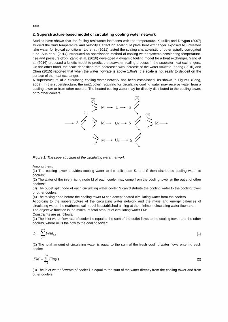
A superstructure of a circulating cooling water network has been established, as shown in Figure1 (Feng,
2009). In the superstructure, the unit(cooler) requiring for circulating cooling water may receive water from a
cooling tower or from other coolers. The heated cooling water may be directly distributed to the cooling tower,
or to other coolers.
Figure 1: The superstructure of the circulating water network
Among them:
(1) The cooling tower provides cooling water to the split node S, and S then distributes cooling water to
coolers;
(2) The water of the inlet mixing node M of each cooler may come from the cooling tower or the outlet of other
coolers;
(3) The outlet split node of each circulating water cooler S can distribute the cooling water to the cooling tower
or other coolers;
(4) The mixing node before the cooling tower M can accept heated circulating water from the coolers.
According to the superstructure of the circulating water network and the mass and energy balances of
circulating water, the mathematical model is established aiming at the minimum circulating water flow rate.
The objective function is the minimum total amount of circulating water FM:
Constraints are as follows.
(1) The inlet water flow rate of cooler i is equal to the sum of the outlet flows to the cooling tower and the other
coolers, where i=j is the flow to the cooling tower:
,
1
j j
i i j
j
F Fout
(1)
(2) The total amount of circulating water is equal to the sum of the fresh cooling water flows entering each
cooler:
1
( )i i
i
FM Fin i
(2)
(3) The inlet water flowrate of cooler i is equal to the sum of the water directly from the cooling tower and from
other coolers:
1334
,
1
( )j j
i i i j
j
F Fin Fout j i
(3)
(4) The total circulating water is equal to the sum of the flowrate from the coolers to the cooling tower:
;
,
1; 1
( )i i j j
i j
i j
FM Fout i j
(4)
(5) For cooler i, the energy balance at the inlet node is:
,
1
( ) ( )j j
i i i j i
j
F i Tin Fin Twin Fout Tout j i
(5)
(6) Energy balance around the mixing node before the cooling tower is:
;
,
1; 1
( )i i j j
i j i
i j
FM Twout Fout Tout i j
(6)
(7) Heat load of cooler i is:
i i i iq F cp Tout Tin (7)
(8) The outlet temperature should be higher than the inlet temperature for cooler i:
i itout tin (8)
(9) The inlet and outlet temperature restrictions for cooler i are:
i i idtin Thout tin ,i i idtout Thin tout (9)
(10) The return temperature limitation to the cooling tower and outlet water temperature limitation of cooler i:
Twout Tup ,itout Tup (10)
(11) Restriction of the circulating cooling water flowrate:
For the problem of circulating water network revamping, the coolers have been given, and the circulation area
is fixed. Therefore, the circulating water flowrate through a cooler is proportional to the flow of water. The
circulating water flowrate is iu , and circulating cooling water flow is
iF .
As the return temperature increasing will lead to scaling acceleration, when the cooling water outlet
temperature increases, the flowrate needs to increase correspondingly. The constraint of the flowrate at a
given return temperature can be expressed as: 0.02i iu tout .That is
0.02i i iF a tout (11)
3. Case study
The case is from the circulating water network of the diesel hydrogenation unit in a petrochemical plant. The
parameters of the coolers are shown in Table 1. Before the optimization, the circulating cooling water network
is in parallel structure, the outlet temperature of the cooling tower is 26 °C, the return temperature is 38.5 °C,
and the cooling water consumption was 469.8 t/h (130.5 kg/s).
When the permissible return temperature is 55 °C and the minimum heat transfer temperature difference is 10
°C, the impact of cooling water scaling is not taken into consideration first, that is, the flowrate constraint
(Equation 11) is not considered. Gams software is used to calculate the minimum circulating cooling water
consumption, and the result is 57.225 kg/s. From the circulating water network and the specific parameters of
the coolers, the outlet flow and outlet temperature of the coolers are calculated, as shown in Table 2.
1335
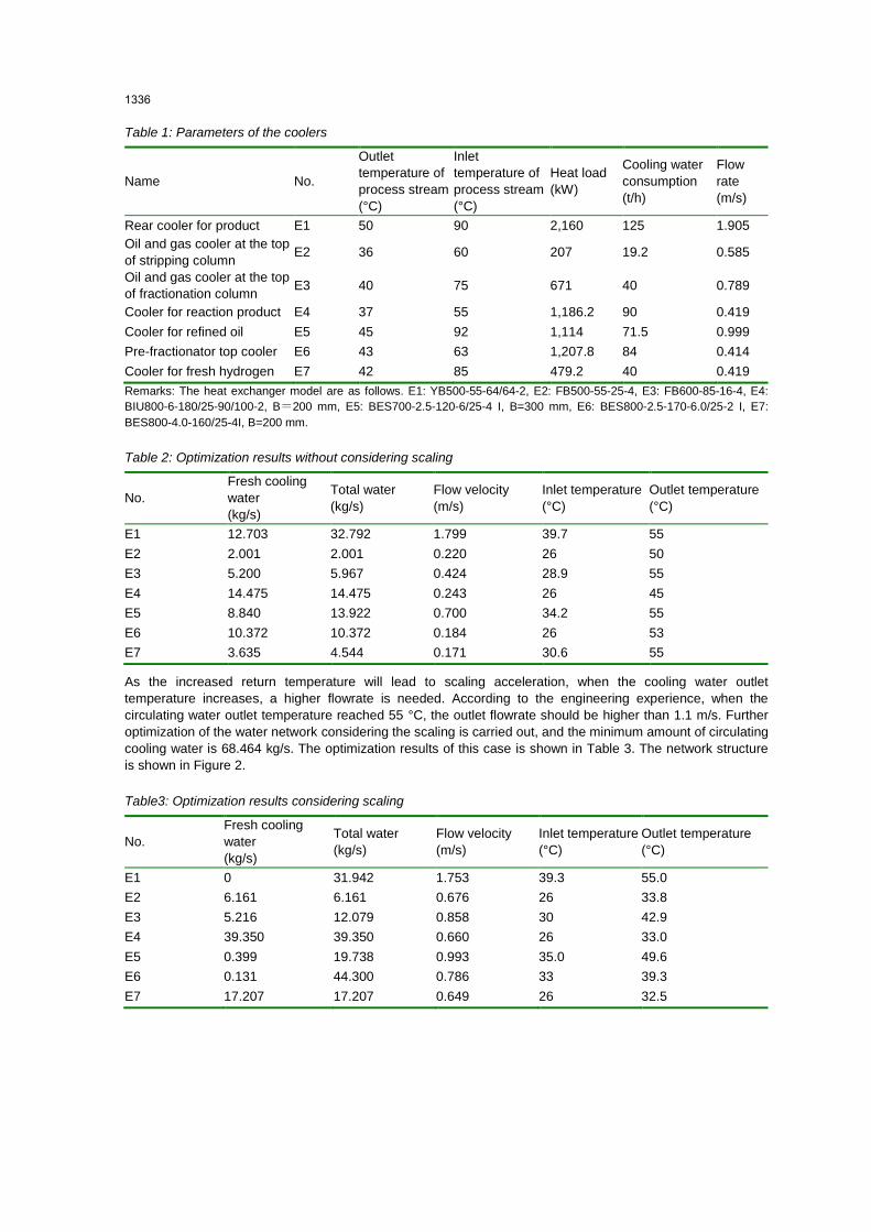
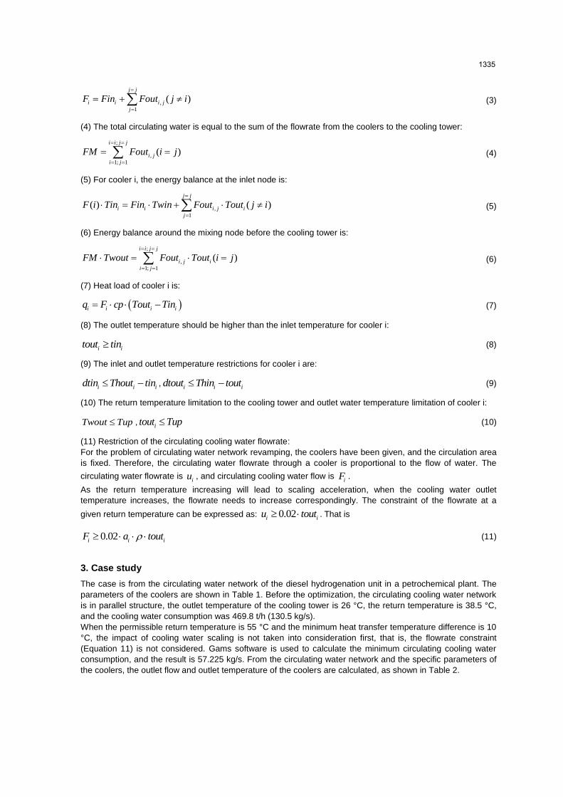
Table 1: Parameters of the coolers
Name No.
Outlet
temperature of
process stream
(°C)
Inlet
temperature of
process stream
(°C)
Heat load
(kW)
Cooling water
consumption
(t/h)
Flow
rate
(m/s)
Rear cooler for product E1 50 90 2,160 125 1.905
Oil and gas cooler at the top
of stripping column E2 36 60 207 19.2 0.585
Oil and gas cooler at the top
of fractionation column E3 40 75 671 40 0.789
Cooler for reaction product E4 37 55 1,186.2 90 0.419
Cooler for refined oil E5 45 92 1,114 71.5 0.999
Pre-fractionator top cooler E6 43 63 1,207.8 84 0.414
Cooler for fresh hydrogen E7 42 85 479.2 40 0.419
Remarks: The heat exchanger model are as follows. E1: YB500-55-64/64-2, E2: FB500-55-25-4, E3: FB600-85-16-4, E4:
BIU800-6-180/25-90/100-2, B=200 mm, E5: BES700-2.5-120-6/25-4 I, B=300 mm, E6: BES800-2.5-170-6.0/25-2 I, E7:
BES800-4.0-160/25-4I, B=200 mm.
Table 2: Optimization results without considering scaling
No.
Fresh cooling
water
(kg/s)
Total water
(kg/s)
Flow velocity
(m/s)
Inlet temperature
(°C)
Outlet temperature
(°C)
E1 12.703 32.792 1.799 39.7 55
E2 2.001 2.001 0.220 26 50
E3 5.200 5.967 0.424 28.9 55
E4 14.475 14.475 0.243 26 45
E5 8.840 13.922 0.700 34.2 55
E6 10.372 10.372 0.184 26 53
E7 3.635 4.544 0.171 30.6 55
As the increased return temperature will lead to scaling acceleration, when the cooling water outlet
temperature increases, a higher flowrate is needed. According to the engineering experience, when the
circulating water outlet temperature reached 55 °C, the outlet flowrate should be higher than 1.1 m/s. Further
optimization of the water network considering the scaling is carried out, and the minimum amount of circulating
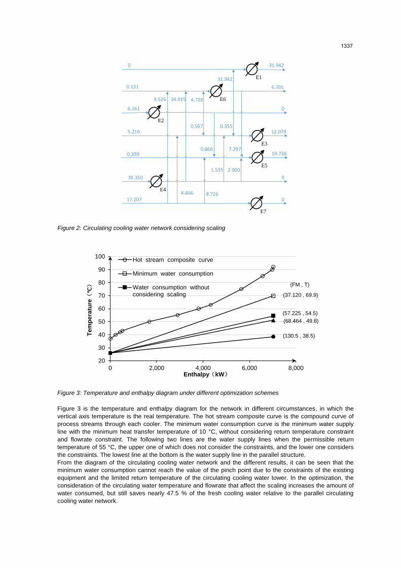
cooling water is 68.464 kg/s. The optimization results of this case is shown in Table 3. The network structure
is shown in Figure 2.
Table3: Optimization results considering scaling
No.
Fresh cooling
water
(kg/s)
Total water
(kg/s)
Flow velocity
(m/s)
Inlet temperature
(°C)
Outlet temperature
(°C)
E1 0 31.942 1.753 39.3 55.0
E2 6.161 6.161 0.676 26 33.8
E3 5.216 12.079 0.858 30 42.9
E4 39.350 39.350 0.660 26 33.0
E5 0.399 19.738 0.993 35.0 49.6
E6 0.131 44.300 0.786 33 39.3
E7 17.207 17.207 0.649 26 32.5
1336
E1
E5
E1
E6
E1
E3
E1
E7
E1
E4
E1
E1
E1
E2
12.0795.216
0
0
6.161
17.207 0
0
19.738
0.131
0.399
39.350
31.942
31.942
4.705
0.355
7.297
4.728
0.567
0.866
34.9154.526
1.535 2.900
4.406 8.726
Figure 2: Circulating cooling water network considering scaling
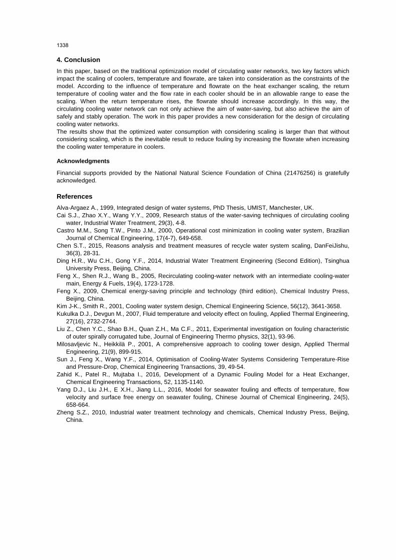
Figure 3: Temperature and enthalpy diagram under different optimization schemes
Figure 3 is the temperature and enthalpy diagram for the network in different circumstances, in which the
vertical axis temperature is the real temperature. The hot stream composite curve is the compound curve of
process streams through each cooler. The minimum water consumption curve is the minimum water supply
line with the minimum heat transfer temperature of 10 °C, without considering return temperature constraint
and flowrate constraint. The following two lines are the water supply lines when the permissible return
temperature of 55 °C, the upper one of which does not consider the constraints, and the lower one considers
the constraints. The lowest line at the bottom is the water supply line in the parallel structure.
From the diagram of the circulating cooling water network and the different results, it can be seen that the
minimum water consumption cannot reach the value of the pinch point due to the constraints of the existing
equipment and the limited return temperature of the circulating cooling water tower. In the optimization, the
consideration of the circulating water temperature and flowrate that affect the scaling increases the amount of
water consumed, but still saves nearly 47.5 % of the fresh cooling water relative to the parallel circulating
cooling water network.
20
30
40
50
60
70
80
90
100
0 2,000 4,000 6,000 8,000
Te
mp
era
ture(℃)
Enthalpy(kW)
Hot stream composite curve
Minimum water consumption
Water consumption withoutconsidering scaling (37.120 , 69.9)
(130.5 , 38.5)
(68.464 , 49.8)
(57.225 , 54.5)
(FM , T)
1337
4. Conclusion
In this paper, based on the traditional optimization model of circulating water networks, two key factors which
impact the scaling of coolers, temperature and flowrate, are taken into consideration as the constraints of the
model. According to the influence of temperature and flowrate on the heat exchanger scaling, the return
temperature of cooling water and the flow rate in each cooler should be in an allowable range to ease the
scaling. When the return temperature rises, the flowrate should increase accordingly. In this way, the
circulating cooling water network can not only achieve the aim of water-saving, but also achieve the aim of
safely and stably operation. The work in this paper provides a new consideration for the design of circulating
cooling water networks.
The results show that the optimized water consumption with considering scaling is larger than that without
considering scaling, which is the inevitable result to reduce fouling by increasing the flowrate when increasing
the cooling water temperature in coolers.
Acknowledgments
Financial supports provided by the National Natural Science Foundation of China (21476256) is gratefully
acknowledged.
References
Alva-Argaez A., 1999, Integrated design of water systems, PhD Thesis, UMIST, Manchester, UK.
Cai S.J., Zhao X.Y., Wang Y.Y., 2009, Research status of the water-saving techniques of circulating cooling
water, Industrial Water Treatment, 29(3), 4-8.
Castro M.M., Song T.W., Pinto J.M., 2000, Operational cost minimization in cooling water system, Brazilian
Journal of Chemical Engineering, 17(4-7), 649-658.
Chen S.T., 2015, Reasons analysis and treatment measures of recycle water system scaling, DanFeiJishu,
36(3), 28-31.
Ding H.R., Wu C.H., Gong Y.F., 2014, Industrial Water Treatment Engineering (Second Edition), Tsinghua
University Press, Beijing, China.
Feng X., Shen R.J., Wang B., 2005, Recirculating cooling-water network with an intermediate cooling-water
main, Energy & Fuels, 19(4), 1723-1728.
Feng X., 2009, Chemical energy-saving principle and technology (third edition), Chemical Industry Press,
Beijing, China.
Kim J-K., Smith R., 2001, Cooling water system design, Chemical Engineering Science, 56(12), 3641-3658.
Kukulka D.J., Devgun M., 2007, Fluid temperature and velocity effect on fouling, Applied Thermal Engineering,
27(16), 2732-2744.
Liu Z., Chen Y.C., Shao B.H., Quan Z.H., Ma C.F., 2011, Experimental investigation on fouling characteristic
of outer spirally corrugated tube, Journal of Engineering Thermo physics, 32(1), 93-96.
Milosavljevic N., Heikkilä P., 2001, A comprehensive approach to cooling tower design, Applied Thermal
Engineering, 21(9), 899-915.
Sun J., Feng X., Wang Y.F., 2014, Optimisation of Cooling-Water Systems Considering Temperature-Rise
and Pressure-Drop, Chemical Engineering Transactions, 39, 49-54.
Zahid K., Patel R., Mujtaba I., 2016, Development of a Dynamic Fouling Model for a Heat Exchanger,
Chemical Engineering Transactions, 52, 1135-1140.
Yang D.J., Liu J.H., E X.H., Jiang L.L., 2016, Model for seawater fouling and effects of temperature, flow
velocity and surface free energy on seawater fouling, Chinese Journal of Chemical Engineering, 24(5),
658-664.
Zheng S.Z., 2010, Industrial water treatment technology and chemicals, Chemical Industry Press, Beijing,
China.
1338