Template forTechnical Procedure · Web viewHave all control power and auxiliary equipment power...
153
Page 1 of 153 Subject: Sandow 5 Integrated Operating Procedure Revision Date: 11/30/10 Procedure No.: LUM-SA5-OPS-0001 Use: In-Hand Effective Date: __11/30/10__ Prepared by: ___________________________________________________ Date: __11/30/10____ Reviewed by: __Gwen Holladay____________________________ __Date: _ _ 2/10/11____ Approved by: ___________________________________________________ Date: __11/30/10____ Required review frequency: Every Year
-
Upload
phungduong -
Category
Documents
-
view
214 -
download
1
Transcript of Template forTechnical Procedure · Web viewHave all control power and auxiliary equipment power...
Page 1 of 104
Subject: Sandow 5 Integrated Operating Procedure
Revision Date: 11/30/10 Procedure No.: LUM-SA5-OPS-0001
Use: In-Hand
Effective Date: __11/30/10__
Prepared by: ___________________________________________________ Date: __11/30/10____
Reviewed by: __Gwen Holladay____________________________ __Date: _ _ 2/10/11____
Approved by: ___________________________________________________ Date: __11/30/10____
Required review frequency: Every Year
Page 2 of 104
Subject: Sandow 5 Integrated Operating Procedure
Revision Date: 11/30/10 Procedure No.: LUM-SA5-OPS-0001
Use: In-Hand
Table of Contents1. Purpose............................................................................................................................................................. 32. Prerequisites.................................................................................................................................................. 3
2.1 Systems, Instruments, and Equipment..........................................................................................................33. Precautions and Limitations..................................................................................................................... 4
3.1 Precautions................................................................................................................................................................43.2 Limitations.................................................................................................................................................................4
4. Instructions..................................................................................................................................................... 64.1 Plant Startup..............................................................................................................................................................64.2 2nd Boiler Startup & and Paralleling.............................................................................................................384.3 Boiler Paralleling..................................................................................................................................................544.4 Normal Plant Ops..................................................................................................................................................574.5 1st Boiler Shutdown.............................................................................................................................................594.6 2nd Boiler and Turbine Shutdown..................................................................................................................65
5. References..................................................................................................................................................... 715.1 Development References..................................................................................................................................71
6. Attachments.................................................................................................................................................. 726.1 Attachment A, : 5A Boiler Pre-Startup Checksheet................................................................................726.2 Attachment B, : 5B Boiler Pre-Startup Checksheet................................................................................72
Page 3 of 104
Subject: Sandow 5 Integrated Operating Procedure
Revision Date: 11/30/10 Procedure No.: LUM-SA5-OPS-0001
Use: In-Hand
1. PurposeThe purpose of this document is to provide information for Operations regarding safety precautions, limitations, and a guideline for startup, normal operations, and shutdown of the plant.
2. PrerequisitesEnsure that the following prerequisites are complete before performing this procedure.
2.1 Systems, Instruments, and Equipment
2.1.1 Switchyard and transmission lines are clear of holds and ready for service.
[2.1.2] All uUnit 5 auxiliary equipment LOTO’s should be clear with the exception of LOTO’s on redundant equipment. Bring Aany redundant equipment that remains out of service should be brought to the attention of the shift supervisor.
[2.1.3] Have Ssufficient quantities of demineralized water, condensate, boiler chemicals, NH3, fuel oil, lignite, and bed material available to support startup.
[2.1.4] Have Aall control power and auxiliary equipment power available.
[2.1.5] Verify Vvalve lineups for the following systems verified:
Circulating Water & and Cooling Tower Makeup Service Water Closed Cooling Water Instrument & and Service Air Condensate Makeup Condensate Feedwater Condenser Air Removal Turbine Seal Oil Turbine Lube Oil Turbine Stator Cooling Generator Hydrogen Baghouse Boiler Blowdown Fuel Oil Auxiliary Steam Main Steam Extraction Steam
Page 4 of 104
Subject: Sandow 5 Integrated Operating Procedure
Revision Date: 11/30/10 Procedure No.: LUM-SA5-OPS-0001
Use: In-Hand
3. Precautions and LimitationsBefore performing the procedure, ensure you understand the following precautions and limitations.
3.1 Precautions
3.1.1 Exposure to excessive negative or positive pressures can result in serious damage to the unit and auxiliary equipment. The following should be in service and operable prior to start-up for control of and protection against excessive furnace pressure or draft.
Furnace draft monitored constantly and automatically controlled to maintain -0.5 in. w.g.
Furnace pressure alarms set at +5.0 in. w.g. and -3.0 in. w.g. Master fuel trip (MFT) at furnace pressure values +8.0 in. w.g. and -8.0 in. w.g. Master fuel trip (MFT) and PA, SA fan trips at furnace pressure of +10 in. w.g. When starting a particular induced draft (ID), primary air (PA), and/or secondary air
(SA) fan(s) is to be started, the corresponding inlet control vanes and outlet isolating (shut-off) dampers (if supplied) should be closed. However, if there are multiple fans, the dampers (and vanes) on the companion idle fans should be open to assure that a clear air flow path (between ID, SA, or PA fan inlet and stack) exists when starting the fans.
[3.1.2] Care should be exercised to insure that proper fuel-air ratio for combustion is maintained. Operate Uunit should be operated with at least 30% excess air flow until 50% load. Operation Operating with less than the minimum expected excess air can be detrimental from the standpoint of combustion, emission performance, and safe operation of the unit.
[3.1.3] On commonly operated valves, such as superheater drains and vents, be careful to should be taken maintain the integrity of the root valves. These valves should never be in a throttled position, and it may be beneficial to leave them open and only close the end valves. The root valve would then only be closed for end valve maintenance or downstream line maintenance. Both valves on waterwall wall drains can be left closed. In all cases, end valves should be closed before closing root valves and opened only after opening the root valve in order to minimize potential root valve seat damage.
3.2 Limitations
[3.2.1] On a cold startup the rate of change in steam drum metal temperature (averaged) should be limited to not exceed 200°⁰F /hr.
[3.2.2] On a cold startup the rate of change in the saturated temperature measured at the boiler steam drum should be limited to 200°⁰F /hr.
DevDocs, 02/11/11,
Exercise care/Be careful to maintain proper fuel-air ratio for combustion.
Page 5 of 104
Subject: Sandow 5 Integrated Operating Procedure
Revision Date: 11/30/10 Procedure No.: LUM-SA5-OPS-0001
Use: In-Hand
[3.2.3] On a cold startup the rate of change in combustion chamber exit gas temperature measured at the cyclone inlet should be limited to 200°⁰F /hr.
[3.2.4] The maximum allowable temperature differential between the top and bottom steam drum metal is 200°⁰F.
[3.2.5] Never add feedwater to an empty boiler steam drum if the drum metal to feedwater inlet to the drum temperature differential is greater than 200°⁰F.
[3.2.6] The baghouse hopper heater system (5A/B-QB-ME-512 thru 562) must be in service at least 10- to 12 hours prior to introducing any material or flue gas into the system.
[3.2.7] Using steam drum metal thermocouples to monitor steam drum metal temperatures, do not exceed a temperature differential of 200°⁰F of between top metal temperatures toand bottom metal temperatures at any time. This is primarily a consideration during either startup or cool-down of the boiler.
3.2.1[3.2.8] The unit can be operated up to the temperature limits indicated in the table below. To protect the equipment, the operator should correct any condition which has caused an alarm to sound.
SectionLocation of Temp
MeasurementMax Long Term
Temp (°ºF)Max Short Term
Temp (°ºF)*
Primary Superheater Tubes to Outlet Header 802 822
Intermediate Superheater
Tubes to Outlet Header 983 1003
Finishing Superheater Tubes to Outlet Header 1144 1169
Reheater I Tubes to Outlet Header 1190 1215
Reheater II Tubes to Outlet Header 1153 1171
DevDocs, 02/11/11,
Suggest: “limit the difference in temperature between top metal and bottom metal to 200°F at all times.”

Page 6 of 104
Subject: Sandow 5 Integrated Operating Procedure
Revision Date: 11/30/10 Procedure No.: LUM-SA5-OPS-0001
Use: In-Hand
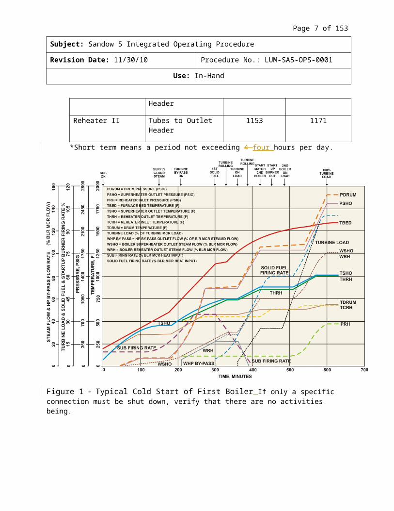
*Short term means a period not exceeding 4 four hours per day.
Figure 1 Typical Cold Start of First Boiler If only a specific connection must be shut down, verify that there are no activities being.
4. Instructions4.1 Plant Startup
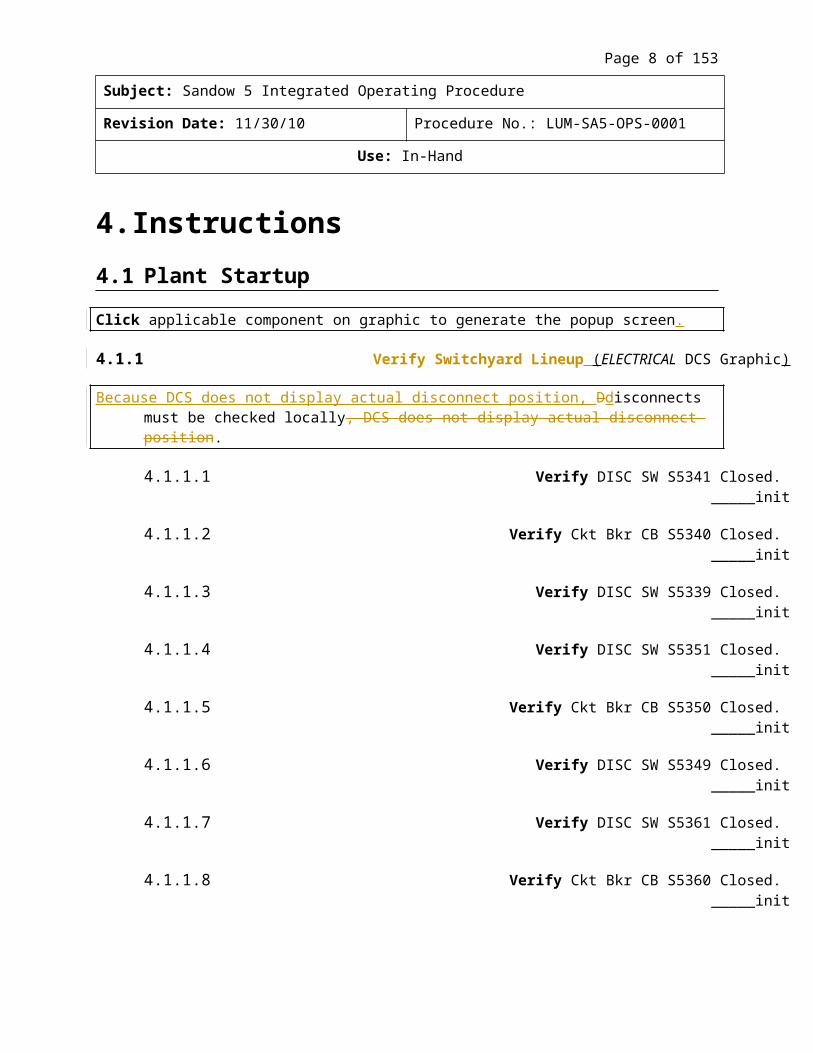
Note Click applicable component on graphic to generate the popup screen.
4.1.1 Verify Switchyard Lineup (ELECTRICAL DCS Graphic)
DevDocs, 02/11/11,
Does this statement belong somewhere in the body of the document?
Page 7 of 104
Subject: Sandow 5 Integrated Operating Procedure
Revision Date: 11/30/10 Procedure No.: LUM-SA5-OPS-0001
Use: In-Hand
[Note] Because DCS does not display actual disconnect position, Ddisconnects must be checked locally, DCS does not display actual disconnect position.
4.1.1.1 Verify DISC SW S5341 Closed. _____init
4.1.1.2 Verify Ckt Bkr CB S5340 Closed. _____init
4.1.1.3 Verify DISC SW S5339 Closed. _____init
4.1.1.4 Verify DISC SW S5351 Closed. _____init
4.1.1.5 Verify Ckt Bkr CB S5350 Closed. _____init
4.1.1.6 Verify DISC SW S5349 Closed. _____init
4.1.1.7 Verify DISC SW S5361 Closed. _____init
4.1.1.8 Verify Ckt Bkr CB S5360 Closed. _____init
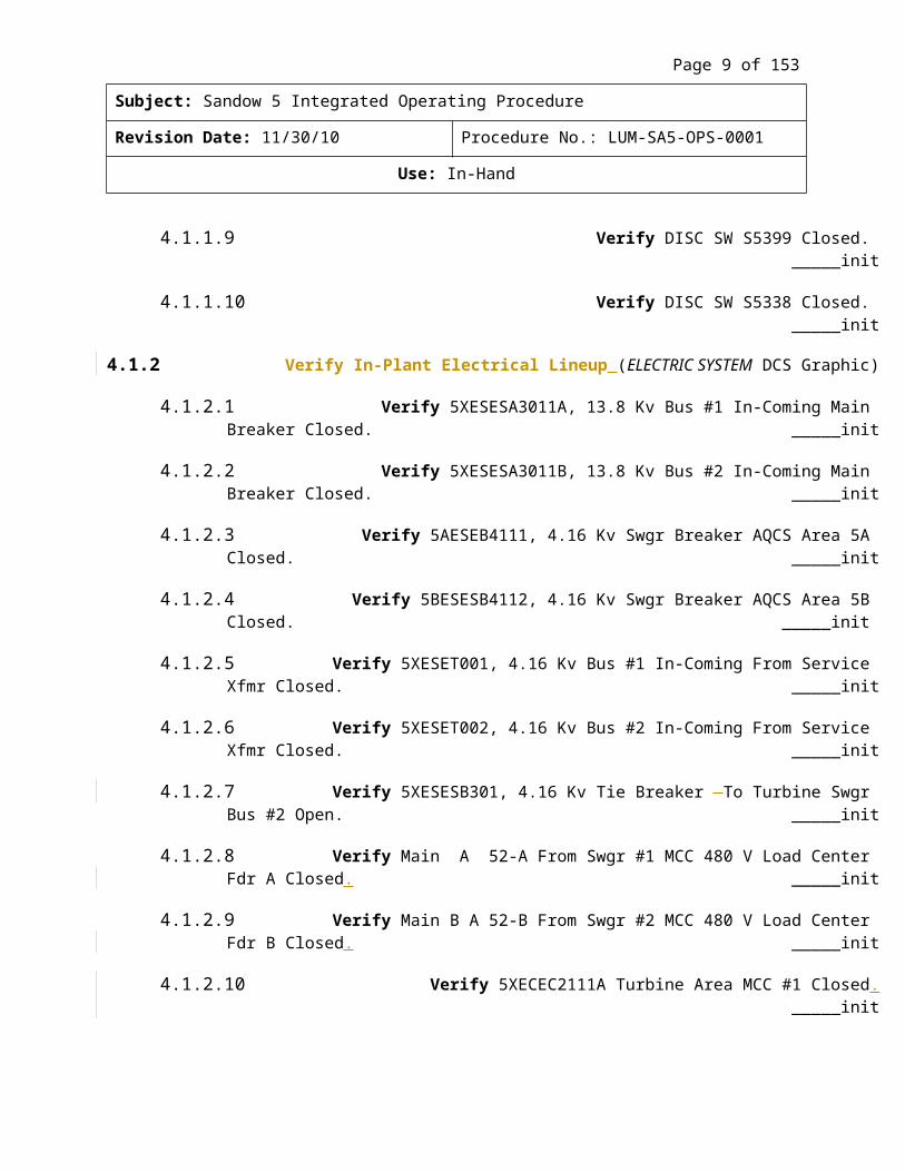
4.1.1.9 Verify DISC SW S5399 Closed. _____init
4.1.1.10 Verify DISC SW S5338 Closed. _____init
4.1.2 Verify In-Plant Electrical Lineup (ELECTRIC SYSTEM DCS Graphic)
4.1.2.1 Verify 5XESESA3011A, 13.8 Kv Bus #1 In-Coming Main Breaker Closed. _____init
4.1.2.2 Verify 5XESESA3011B, 13.8 Kv Bus #2 In-Coming Main Breaker Closed. _____init
4.1.2.3 Verify 5AESEB4111, 4.16 Kv Swgr Breaker AQCS Area 5A Closed. _____init
4.1.2.4 Verify 5BESESB4112, 4.16 Kv Swgr Breaker AQCS Area 5B Closed. _____init
4.1.2.5 Verify 5XESET001, 4.16 Kv Bus #1 In-Coming From Service Xfmr Closed. _____init
4.1.2.6 Verify 5XESET002, 4.16 Kv Bus #2 In-Coming From Service Xfmr Closed. _____init
[4.1.2.7] Verify 5XESESB301, 4.16 Kv Tie Breaker To Turbine Swgr Bus #2 Open. _____init
4.1.2.7[4.1.2.8] Verify Main A 52-A From Swgr #1 MCC 480 V Load Center Fdr A Closed._____init
Page 8 of 104
Subject: Sandow 5 Integrated Operating Procedure
Revision Date: 11/30/10 Procedure No.: LUM-SA5-OPS-0001
Use: In-Hand
4.1.2.8[4.1.2.9] Verify Main B A 52-B From Swgr #2 MCC 480 V Load Center Fdr B Closed._____init
4.1.2.9[4.1.2.10] Verify 5XECEC2111A Turbine Area MCC #1 Closed. _____init
4.1.2.10[4.1.2.11] Verify 5XECEC2111B Turbine Area MCC #2 Closed. _____init
[4.1.2.12] Verify 5XECEC2111C Essential MCC Closed. _____init
Page 9 of 104
Subject: Sandow 5 Integrated Operating Procedure
Revision Date: 11/30/10 Procedure No.: LUM-SA5-OPS-0001
Use: In-Hand
4.1.3 Service Water Startup (SERVICE WATER DCS Graphic)
4.1.3.1 Verify Mine Depressurization Water is in service. _____init
4.1.3.2 Verify Service Water Tank Level is at operating level (7-13 ft). _____init
[4.1.3.3] IF If this is the initial system startup, THEN then Vverify high point vents in the system are OPENOpen.
4.1.3.3[4.1.3.4] Start Service Water Pump 1A or 1B. _____init
[4.1.3.5] Place the Service Water Tank Level Controller into AUTOAuto.
[4.1.3.6] Place remaining Service Water Pump in AutoAUTO. _____init
[4.1.3.7] IFIf Water Lab needs to make Plant Demin water, THENthen Sstart both Demin Water Pumps 1A and 1B. _____init
4.1.3.4[4.1.3.8] Monitor the vent valves in various pipe segments. Close each valve after a continuous stream of water is running. ____ Init
Close each valve after a continuous stream of water is established. ____ Init
[4.1.3.9] Identify when water emerges from the most remote vent valve in order to verify that the entire system and pipeline has have been filled. ____ Init
4.1.4 Cooling Tower Makeup Startup (MAKEUP WATER DCS Graphic)
[Note] The Strainer Back Wash Pump is given a start withstarted by the 1st Makeup Pump and remains running as long as a Makeup Pump is running.
[4.1.4.1] Start one(1) or two(2) Makeup Pumps (1A, 1B, or 1C) in MANUAL Manual to fill Cooling Tower Basin to operating level of 5.0 ft. ____init
4.1.4.1[4.1.4.2] ADJUST Basin Level Control Valve as needed to fill the Cooling Tower Basin and to control Makeup Water Pump amps less than 113 amps. ____init
WHEN When Basin level reaches 5.0 ft, THEN Pplace Basin Control Valve (5X-WL-LV043) in Auto.AUTO. ____init
[4.1.4.3] Place one(1) running Makeup Water Pump in ManualMANUAL. ____init
DevDocs, 02/11/11,
Not clear. Is it “keep/maintain Makeup Water Pump amps at less than…” or “control Makeup…amps that are less than…” ??
DevDocs, 02/11/11,
or “started with”??
DevDocs, 02/11/11,
Since this isn’t a list, just make it a separate statement (no letter needed).
DevDocs, 02/11/11,
Vague term. Maybe “several”?
DevDocs, 02/11/11,
Demineralized, as in sect 2.1.3?
Page 10 of 104
Subject: Sandow 5 Integrated Operating Procedure
Revision Date: 11/30/10 Procedure No.: LUM-SA5-OPS-0001
Use: In-Hand
[4.1.4.4] Place another Makeup Water Pump in AutoAUTO. ____init
[4.1.4.5] Place the remaining Makeup Pump in STANDBYStandby. ____init
4.1.5 Circulating Water System Startup (CIRC WTR PUMPS DCS Graphic)
[4.1.5.1] Start half (11) the Cooling Tower Fans or as many as the number needed for cooling. ____init
4.1.5.1[4.1.5.2] Verify normal operating level in basin (5 ft.) before putting circulating water pumps in service. ____init
[4.1.5.3] IF If both Circulating Water Pumps (CWP) have been off line, THEN then Pprime the Circulating Water System.
[(a)] Use the Makeup Pump System and the Raw Water Initial Fill Valve located on the L riser (5X-WL-V227). (located on the L riser) ____init
(a)[(b)] Vent until air is removed from CWPs and Condenser Waterbox. ____init
(b)[(c)] Close vents and Raw Water Initial Fill Valve (5X-WL-V227). ____init
4.1.5.2[4.1.5.4] Open some of the risers to be put into operation. ____init
[4.1.5.5] Click on DETAILS/LO PMP Ppushbutton. Start CWP Lube Oil Pump for Circulating Water Pump to be started.
Start CWP Lube Oil Pump for Circulating Water Pump to be started. ____init
[4.1.5.6] Start CWP 1A or 1B and place in AUTOAuto. ____init
[Note] Discharge Valve opens when pump is started. The pump discharge valves (5X-WL-HV005A) &and (5X-WL-HV-005B) have 10 seconds to reach 20% open and 120 seconds to reach 100% open or pumps will trip.
4.1.6 Closed Cooling Water (CCW) Startup (CLOSED COLNG WTR DCS Graphic)
[4.1.6.1] IF If this is the initial system startup, THEN then Ffill and Vvent the system at all the high point’s. ____init
[(a)] Fill and Vvent Closed Cooling Water Pumps 5X-WB-MP-001A & and B.o Pump 001A Vents 5X-WB-V713 & and V711 ____inito Pump 001B Vents 5X-WB-V714 & and V712 ____init
Page 11 of 104
Subject: Sandow 5 Integrated Operating Procedure
Revision Date: 11/30/10 Procedure No.: LUM-SA5-OPS-0001
Use: In-Hand
[(b)] Verify that Suction & Discharge Valves to beare OPEN open on both pumps.o Pump 001A Valves 5X-WB-V001 & and V003 ____inito Pump 001B Valves 5X-WB-V004 & and V006 ____init
[(c)] After filling and venting the system, CLOSE close the Discharge Valves. ____init
[4.1.6.2] Verify CCW Head Tank has a level of 1.5-3.5 ft and is operational (1.5 – 3.5 ft). ____init
4.1.6.1[4.1.6.3] Verify CCW Pumps are ready for service. ____init
[4.1.6.4] Start Closed Cooling Water Pump 1A or 1B in MANUALManual. ____init
[4.1.6.5] Gradually openOPEN CCW Pump Discharge Valve for the running CCW Pump, allowing pressure to build up slowly.o 5X-WB-V003 CCW Pmp 1A ____inito 5X-WB-V006 CCW Pmp 1B ____init
Place remaining CCW Pump in AUTOAuto. ____init
4.1.7 Plant Compressed Air Startup
[4.1.7.1] Verify both Ccompressors are ready for service. ____init
[4.1.7.2] Line Uup dryers for service. ____init
[4.1.7.3] IF If the Air Compressors are to be run with the ES130 system, THEN then Pplace Air Compressor Local Panel in LAN mode and Control Room Panel in the INTEGRATE Integrate mode. ____init
[4.1.7.4] IF If Air Compressors are to be run from the Local Panel only, THEN then Pplace Compressors in the LOCAL Local mode. ____init
4.1.7.1[4.1.7.5] Start 1A and/or 1B Air Compressor. ____init
[Note] Instrument Isolation Valve (003) setpoint in AUTO 100 psig. Dryer Air/Service Air valve (004) setpoint in AUTO 5500 SCFU.
4.1.8 Condensate Transfer System Startup (COND TRANSFER DCS Graphic)
4.1.8.1 Verify Condensate Transfer Pumps are ready for operation. ____init
[4.1.8.2] Verify Condensate Storage Tank has a proper operating level (15-28 ft ). ____init
DevDocs, 02/11/11,
“should be in” ?? (same in second sentence)
DevDocs, 02/11/11,
What determines which one(s) to start?
Page 12 of 104
Subject: Sandow 5 Integrated Operating Procedure
Revision Date: 11/30/10 Procedure No.: LUM-SA5-OPS-0001
Use: In-Hand
4.1.8.2[4.1.8.3] Start Condensate Transfer Pump 1A or 1B. Place remaining Condensate Transfer Pump in Auto. ____init
Place remaining Condensate Transfer Pump in AUTO. ____init
4.1.9 Filling Condenser Hotwell (COND DCS Graphic)
[4.1.9.1] Prior ToBefore transferring water to the condenser hotwellHotwell, Vverify with Lab that Condensate Storage Tank chemistry is within specs.o Sodium <3 ppb ____inito Chloride <3 ppb ____inito Silica, as SIO2 <10 ppb ____inito TSS 0 ppb ____inito Specific Cond <0.1 umhos/cm ____init
[4.1.9.2] Use Emergency Makeup Valve (5X-AD-LV016) in ManualMANUAL to bring Condenser Level up to -2 inches. Place Emergency Makeup Valve in Auto. ____init
Place Emergency Makeup Valve in AUTO. ____init
[4.1.9.3] Verify Normal Makeup Valve (5X-AD-LV001) is in ManualMANUAL and Closed CLOSED until vacuum is established in the Condenser. ____init
[4.1.9.4] Verify Condenser Flash Box Temp Valve (5X-AD-V013) is in AutoAUTO with a 120°⁰F setpoint. ____init
[4.1.9.5] Verify Condenser Minimum Recirc Valve (5X-AD-FV018) is in AutoAUTO with a 1750 KPPH setpoint. ____init
[4.1.9.6] Verify Condenser Hotwell Reject Valve (5X-AD-LV002) is in AutoAUTO with a +10 inch setpoint. ____init
4.1.10 Baghouse Hopper Heaters Startup
[4.1.10.1] Verify the Baghouse Hopper Heaters are in operationoperating. ____init
[Note] IF If there is ash in the Hoppers, THEN then Eensure the Heaters are in operationoperating at all times.
4.1.11 Turbine Seal Oil System Startup (#18 TCS)
4.1.11.1 Start Seal Oil Tank Heaters FG. ____init
Page 13 of 104
Subject: Sandow 5 Integrated Operating Procedure
Revision Date: 11/30/10 Procedure No.: LUM-SA5-OPS-0001
Use: In-Hand
4.1.11.2 Start Seal Oil system FG. ____init
[(a)] Verify Seal Oil Pump # 1 Or or #2 starts.STARTS ____Init
[(b)] Verify Exhaust Blower # 1 or #2 starts.STARTS ____init
[(c)] Verify Vacuum pump, Vacuum Seal Oil pump, DE (Drive End) Seal Oil pump, and NDE (Non Drive End) Seal Oil pump start.START ____init
4.1.12 Turbine Lube Oil System Startup (#3 TCS)
4.1.12.1 Start Lube Oil Tank Heaters FG. ____init
4.1.12.2 Start Lube Oil system FG. Verify Oil Tank Vapor Extractor, Auxiliary Lube Oil Pump, and Jacking Oil Pump start. ____init
Verify Oil Tank Vapor Extractor, Auxiliary Lube Oil Pump, and Jacking Oil Pump START ____init
4.1.13 Turbine Turning Gear System Startup (#3 TCS)
4.1.13.1 Start Turning Gear system FG. ____init
Note Turbine turns at 16.2 rpm.
4.1.13.2 Determine Minimum Time Requirements for Turning Gear (per ALSTOM). ____inito Turbine secured less than 24 hours = 2 hours on turning gearo Turbine secured 1 to 7 days = 6 hours on turning gearo Turbine secured 7 to 30 days = 12 hours on turning gear o Turbine secured greater longer than 30 days = 24 hours on turning gear
4.1.14 Turbine Stator Cooling System Startup (#19 TCS)
4.1.14.1 Start Stator Cooling system FG. Verify #1 or #2 Stator Cooling Pump starts. ____init
Verify #1 or #2 Stator Cooling Pump STARTs ____init
4.1.15 Hydrogen Circulating Fans Startup (#20 TCS)
4.1.15.1 Start Hydrogen Circulating Fans at the local panel. ____init
[4.1.15.2] Verify Hydrogen pressure is 55 - 65 psig. ____init
DevDocs, 02/11/11,
Is this an acronym?
Page 14 of 104
Subject: Sandow 5 Integrated Operating Procedure
Revision Date: 11/30/10 Procedure No.: LUM-SA5-OPS-0001
Use: In-Hand
4.1.16 Turbine Drain Valve (#10 and #11 TCS)
4.1.16.1 Start Turbine Drain Valve FG. ____init
4.1.17 Preparation For Startup And Boiler Filling Valve Line Up
[Note] Normal startup process is to start both boilers at the same time and allowing one to get ahead of the other by a few hours due to the lack of atomizing air for simultaneous boiler firing. When the lead boiler drum pressure gets to about 400 psig, the air heater soot blowers can be transitioned from air to steam, thereby increasing the availability of atomizing air to the process. (SUBs)
[4.1.17.1] Perform Complete Attachment A: 5A Boiler Pre-Startup Checksheet and/or Attachment B: 5B Boiler Pre-Startup Checksheet as applicable. ____init
4.1.18 Condensate System Startup (CONDENSER DCS Graphic)
[4.1.18.1] Verify Hotwell is at operational level (-2 or greater ). ____init
4.1.18.1[4.1.18.2] Verify flow path thru Feedwater Heaters #7, #6, and #5.
(a) On HEATERS 6 & 7 DCS Graphic,
[(i)] Verify FW Heater 7 Inlet MOV (5X-AD-HV027) and FW Heater 5 Inlet MOV (5X-AD-HV031) are Open.OPEN ____init
OR
[(ii)] Verify FW Heater 6 & 7 Bypass MOV (5X-AD-HV030) is Open.OPEN ____init
[(b)] Verify FW Heater 5 Inlet Isol Valve (5X-AD-V096) and FW Heater 5 Outler Isol Valve (5X-AD-V065) are Open.OPEN ____init
OR
[(c)] Verify FW Heater 5 Bypass Valve (5X-AD-V102) is Open.OPEN ____init
[4.1.18.3] Maintain DA Block Valve MOV (5X-AD-HV044) and Control Valve (5X-AD-LCV058) ClosedCLOSED until Condensate Pump and line pressure are equal.
____init
4.1.18.2[4.1.18.4] Line Up both Condensate Suction Strainers. ____init
[4.1.18.5] Verify Condendsate Pump Discharge Valve (5X-AD-V014) is ClosedCLOSED.____init
DevDocs, 02/11/11,
Does this belong here?
Page 15 of 104
Subject: Sandow 5 Integrated Operating Procedure
Revision Date: 11/30/10 Procedure No.: LUM-SA5-OPS-0001
Use: In-Hand
[4.1.18.6] Verify Condensate Pump Discharge Bypass Valve (5X-AD-V095) is Open.OPEN____init
[4.1.18.7] Verify Condensate Pump is primed by OPENING opening the Vent Valve (5X-AD-V016). ____init
[4.1.18.8] Verify Condensate Minimum Flow Recirculation Valve (5X-AD-FV018) is ready for operation and in AutoAUTO. ____ Init
[Note] The condensate pump (5X-AD-MP-001) should be started with the condensate transfer pump (5X-SC-MP-007A/B) in service and with a rising level in the condenser hHotwell.
4.1.18.3[4.1.18.9] Start Condensate Pump. When Condensate Pump is running, open Condensate Pump Discharge Valve (5X-AD-HV014). ____init
WHEN Condensate Pump indicates running, THEN Open Condensate Pump Discharge Valve (5X-AD-HV014). ____init
4.1.18.4[4.1.18.10] Vent Condensate line. ____init
4.1.18.5[4.1.18.11] Vent the gland steam condenser. ____init
[Caution] Wear all required Personal Protective Equipment (PPE). When venting a feedwater heater, only crack open the vent to avoid getting burned or wet or worse getting burned from by the hot water.
4.1.18.6[4.1.18.12] Vent the water side on the feedwater heaters. 7A vent 5X-AD-V812 ____init 7B vent 5X-AD-V711 ____init 6A vent 5X-AD-V706 ____init 6B vent 5X-AD-V713 ____init 5 vent 5X-AD-V708 ____init 3 vent 5X-AE-V707 ____init 2 vent 5X-AE-V708 ____init 1 vent 5X-AE-V747 ____init 1 vent 5X-AE-V748 ____init
4.1.18.7[4.1.18.13] Monitor the Condensate System for abnormal conditions. ____init
Note Condensate Storage Tank Level alarms are Low 5’ High 26.5.’
4.1.18.8[4.1.18.14] Monitor Condensate Storage Tank level.
DevDocs, 02/11/11,
“merely” or “just”?
Page 16 of 104
Subject: Sandow 5 Integrated Operating Procedure
Revision Date: 11/30/10 Procedure No.: LUM-SA5-OPS-0001
Use: In-Hand
4.1.19 Deaerator Fill (HTR 5 & DEAERATOR DCS Graphic)
4.1.19.1 Open DA Inlet Block Valve (5X-AD-HV044). ____init
[4.1.19.2] Slowly Oopen DA Level Control Valve (5X-AD-LV058) to fill DA Storage Tank to normal operating level (of -6 inches). ____init
Note You may have to start both Condensate Transfer Pumps 1A and 1B to keep up with the flow.
[4.1.19.3] Monitor Hotwell Llevel while filling DA to prevent Condensate Pump trip due to low Hotwell Llevel. ____init
[4.1.19.4] WhenWHEN normal DA Level is established, THEN Pplace DA Level Control Valve in AutoAUTO with a -6 setpoint. ____init
4.1.20 Feedwater Booster Pump (FWBP) System (BSTR FEED PUMPS DCS Graphic)
4.1.20.1 Verify FWBP is ready for operation. ____init
[4.1.20.2] Place FW Booster Pump Recirculation Valve (5X-AE-FV101A or B) in AutoAUTO with a 1600 KPPH setpoint. ____init
[4.1.20.3] Prime and Vvent the Feedwater Booster Pump suction line, suction basket strainers, and Feedwater Booster Pump, using the vent valves for Pumps A/B. Pump A vent valve: 5X-AE-V702 ____init Pump B vent valve: 5X-AE-V704 ____init
[4.1.20.4] Select ManualMANUAL control for the Feedwater Booster Pump to be started.____init
[Note] WhenWHEN the Recirc Valve OPENs opens to 80%, THEN the FWBP will start.
4.1.20.2[4.1.20.5] Start Feedwater Booster Pump 1A or 1B. Verify that the Minimum Flow Valve (5X-AE-FV101A or B) opens and maintains 1600 KPPH flow. ____init
Caution Minimum Feedwater Booster Pump recirculating water flow must be maintained to prevent Pump overheating.
Verify the Minimum Flow Valve (5X-AE-FV101A or B) OPENS and maintains 1600 KPPH flow. ____init
[4.1.20.6] Place Feedwater Booster Pump Controller in AutoAUTO. ____init
DevDocs, 02/11/11,
Suggest “To prevent pump from overheating, maintain the minimum recirculating water flow by Feedwater Booster Pump.”
Page 17 of 104
Subject: Sandow 5 Integrated Operating Procedure
Revision Date: 11/30/10 Procedure No.: LUM-SA5-OPS-0001
Use: In-Hand
[4.1.20.7] WhenWHEN FWBP is at normal speed, THEN Sslowly Oopen FW Booster Pump Discharge Manual Bypass Valve to equalize pressure in discharge line to about 400-500 psig. FWBP 1A 5X-AE-V100 ____init FWBP 1B 5X-AE-V101 ____init
[4.1.20.8] WhenWHEN pressure is equalized, THEN slowly OPEN open the FW Booster Pump Discharge MOV (5X-AE-HV503A or B). ____init
[4.1.20.9] AfterAFTER FW Booster Pump Discharge MOV OPENSopens, THEN CLOSE close Manual Bypass Valve. FWBP 1A 5X-AE-V100 ____init FWBP 1B 5X-AE-V101 ____init
4.1.20.3[4.1.20.10] Fill IP Feedwater Heaters 3 and 2 slowly after opening the heater vents. #3 Heater Vent Valve 5X-AE-V707 ____init #2 Heater Vent Valve 5X-AE-V708 ____init
4.1.20.4[4.1.20.11] Close Feedwater Heater Vent Valves once air is completely vented from the feedwater heaters and a steady stream of water appears. #3 Heater Vent Valve 5X-AE-V707 ____init #2 Heater Vent Valve 5X-AE-V708 ____init
4.1.20.5[4.1.20.12] The feedwater heaters are ready to be put in service.
[4.1.20.13] Fill remainder of Feedwater System by:
(a) Opening the Boiler Feed Pump Bypass Valve (5X-AE-V059). ____init
[(b)] Closing BFP Discharge Valve (5X-AE-HV502A) for Pump A and (5X-AE-HV502B) for Pump B. ____init
[Note] Slowly fill HP Feedwater hHeater 1 should be filled slowly through the discharge valve bypass on the boiler feed Pump (5X-AE-V059) after OPENING opening the heater vents (5X-AE-V747/V748/V724/V725).
4.1.20.6 WhenWHEN air is completely vented from the Feedwater Heater #1 and a steady stream of water appears, THEN Cclose the Feedwater Heater vents. 5X-AE-V747 ____init 5X-AE-V748 ____init
4.1.20.7[4.1.20.14] The Feedwater Heater #1 is ready to be put into service.
Page 18 of 104
Subject: Sandow 5 Integrated Operating Procedure
Revision Date: 11/30/10 Procedure No.: LUM-SA5-OPS-0001
Use: In-Hand
[Note] The use of * in titles denotes a wild card used to prevent repeating titles for similar items. fFor example, Boiler A Stm & Wtr and Boiler B Stm & Wtr would simply be Boiler * Stm & Wtr, and user would substitute applicable A/B/C depending upon component or boiler chosen.
4.1.21 Economizer And Boiler Drum Fill (BOILER * STM & WTR DCS Graphic)
[Note] Initial fill can also be performed using Cold Fill with Condensate Transfer Pumps through 5*-AE-V074 & and 75 as long as drum is vented and drum temperature < 200°⁰F above condensate temperature.
4.1.21.1 Open FW Economizer Isolation Valve (5*-AA-HV501). ____init
[4.1.21.2] Slowly Oopen Stm Drum Startup Control Valve (5*-AE-V032B) to fill Drum to a startup level of -6 inches. ____init
4.1.21.2[4.1.21.3] Monitor DA and Hotwell levels while filling Boiler Drum. ____init
[4.1.21.4] WhenWHEN air is vented from the economizer, THEN Cclose the economizer vent valves.
(a) 5*-AA-V0525 ____init
Note Close root valve last to prevent damaging valve.
(b) 5*-AA-V0524 (root) ____init
4.1.22 Baghouse Air Compressor
4.1.22.1 Start Baghouse Air Compressor A or B. ____init
4.1.23 Low Pressure fans and Medium Pressure Fluidizing Blowers (ACQS FL AIR/COMP DCS Graphic)
[Note] Start the THE LP Fluidization Air System should be started two(2) hours prior to the startup ofstarting the Ash Recirc System.
[4.1.23.1] Place North and South LP Fluidizing Air Fans in Auto.AUTO ____init
[4.1.23.2] Place North and South MP Fluidizing Air Blower in Auto.AUTO ____init
[4.1.23.3] Verify MP & and LP Air Heaters are in Auto.AUTO.
DevDocs, 02/11/11,
Should this have some text?
DevDocs, 02/11/11,
Should this have some text?
Page 19 of 104
Subject: Sandow 5 Integrated Operating Procedure
Revision Date: 11/30/10 Procedure No.: LUM-SA5-OPS-0001
Use: In-Hand
[4.1.23.4] Click on the AIR SLIDE START/STOP PpushBbutton. ____init
[(a)] On the popup screen, Sselect START.
[(b)] Verify a North or South LP Fan and MP Blower start.START ____init
[(c)] Verify both MP & and LP air heaters energize. ____init
[4.1.23.5] Start LP and MP Aair Hheaters.
4.1.24 Air Heater (AIR HEATER DCS Graphic)
[4.1.24.1] Place Support Bearing Oil Unit in Auto.AUTO ____init
[4.1.24.2] Place Guide Bearing Oil Unit in Auto.AUTO ____init
[4.1.24.3] Verify Guide Bearing Cooling Fan is operational (Nno Yyellow Hhalo around Ffan means breaker is OK). ____init
4.1.24.1[4.1.24.4] Verify the Sector Plates are retracted. ____init
4.1.24.2[4.1.24.5] Start Air Heater AC Drive Motor. Verify Air Motor is ready for service.____init
Verify Air Motor ready for service ____init
4.1.25 Induced (ID) Fan system (ID FAN AUX DCS Graphic)
[4.1.25.1] Verify ID Fan Hydraulic Reservoir Heaters in Auto.AUTO ____init
4.1.25.1[4.1.25.2] Start ID Fan Hydraulic Oil Pump A or B. Place remaining ID Fan Hydraulic Oil Pump in Auto. ____init
Place remaining ID Fan Hydraulic Oil Pump in AUTO ____init
[4.1.25.3] Verify ID Fan Lube Oil Reservoir Heaters in Auto.AUTO ____init
4.1.25.2[4.1.25.4] Start ID Fan Lube Oil Pump A or B. Place remaining ID Fan Lube Oil Pump in Auto. ____init
Place remaining ID Fan Lube Oil Pump in AUTO ____init
4.1.25.3[4.1.25.5] Start a Diffuser Seal Air Fan A or B. Place remaining Diffuser Seal Air Fan in Auto. ____init
Place remaining Diffuser Seal Air Fan in AUTO ____init
Page 20 of 104
Subject: Sandow 5 Integrated Operating Procedure
Revision Date: 11/30/10 Procedure No.: LUM-SA5-OPS-0001
Use: In-Hand
4.1.25.4[4.1.25.6] Start a Intermediate Seal Air Fan A or B. Place remaining Intermediate Seal Air Fan in Auto. ____init
Place remaining Intermediate Seal Air Fan in AUTO ____init
4.1.25.5[4.1.25.7] On BLR * GAS AIR SYS DCS Graphic
[(a)] Set ID Fan Blade Pitch Controller (5*-BA-FV020) to 0% (CLOSED Closed for startup). ____init
[(b)] Open both SA Lower Dampers (5*-BA-FV737A & and 737B) to 100% in Manual.MANUAL Leave until after purge is complete. ____init
Leave until after purge is complete
[(c)] Open both SA Middle Dampers (5*-BA-FV733A & and 733B) to 100% in Manual.MANUAL Leave until after purge is complete. ____init
Leave until after purge is complete
[(d)] Open both Hot PA Plenum Dampers (5*-BA-FV711A & and 711B) to 100% in Manual.MANUAL ____init
[(e)] Open SA Inlet Damper (5*-BA-FV721) to 100% in Manual.MANUAL ____init
[(f)] Open both PA Fan Inlet Dampers (5*-BA-FV701A & and 701B) to 100% in Manual.MANUAL ____init
[(g)] Open both PA Fan Outlet Dampers (5*BAFV703A & and 703B) to 100% in Manual.MANUAL ____init
(a)[(h)] Verify an open gas path through the stack. ____init
(b)[(i)] Start ID Fan. ____init
4.1.26 Loop Seal Blower system (BLR * GAS AIR SYS DCS Graphic)
4.1.26.1 VERIFY Loop Seal Blower is ready for operation. ____init
[4.1.26.2] Open Loop Seal Blower Inlet Damper (5*-BA-FV784) to 28% -- 30% in Manual.MANUAL ____init
4.1.26.2[4.1.26.3] Start Loop Seal Blower. ____init
Page 21 of 104
Subject: Sandow 5 Integrated Operating Procedure
Revision Date: 11/30/10 Procedure No.: LUM-SA5-OPS-0001
Use: In-Hand
[Note] Loop Seal Blower can remain in ManualMANUAL until purge is complete so motor does not over amp and trip off.
4.1.27 Secondary Fan (SA) system (PA/SA FAN LUB SYS DCS Graphic)
4.1.27.1 Start SA Fan Lube Oil Pump A or B. Place remaining SA Fan Lube Oil Pump in Auto. ____init
Place remaining SA Fan Lube Oil Pump in AUTO ____init
[4.1.27.2] Verify Lube Oil Cooling Fan is operational (Nno Yyellow Hhalo around Ffan means breaker is OK). ____init
[4.1.27.3] Verify the breaker is ClosedCLOSED on the Lube Oil Tank Heaters and ready for operation. ____init
4.1.27.2[4.1.27.4] On BLR * GAS AIR SYS DCS Graphic
(a) Close SA Inlet Damper (5*-BA-FV721). ____init
[(b)] WhenWHEN Inlet Damper reads 0%, THEN Sstart the SA Fan. ____init
[(c)] Open SA Inlet Damper (5*-BA-FV721) 5% - 10% while monitoring Boiler draft and adjusting ID Fan Blade Pitch (5*-BA-FV020) as needed for Boiler draft control. ____init
[(d)] Place ID Fan Blade Pitch Controller (5*-BA-FV020) in AutoAUTO with a setpoint of -0.5”. inch. ____init
4.1.28 Primary Fan (PA) A and B system (PA/SA FAN LUB SYS DCS Graphic)
[4.1.28.1] Start one(1) PA Fan Lube Oil Pump A or B on both PA Fans A and B. ____init
Place remaining PA Fan Lube Oil Pumps in Auto.AUTO ____init
[4.1.28.2] Verify Lube Oil Cooling Fans are operational (Nno Yyellow Hhalo around Ffan means breaker is OK). ____init
[4.1.28.3] Verify the breaker is ClosedCLOSED on the Lube Oil Tank Heaters and ready for operation. ____init
Page 22 of 104
Subject: Sandow 5 Integrated Operating Procedure
Revision Date: 11/30/10 Procedure No.: LUM-SA5-OPS-0001
Use: In-Hand
4.1.28.1[4.1.28.4] On BLR * GAS AIR SYS DCS Graphic
Note Click applicable component on graphic to generate the popup screen.
[(a)] Close both PA Fan Inlet Dampers (5*-BA-FV701A & and B). ____init
[(b)] Verify A PA Fan Discharge Damper is openOPEN (5*-BA-FV703A). ____init
(a)[(c)] Close B PA Fan Discharge Damper (5*-BA-FV703B). ____init
[Note] When starting the PA fan, the operator must know whether there is bed in the combustion chamber or not. Without bed material, there is no resistance to air flow through the grid nozzles. When bed material is in the combustion chamber, windbox pressure must increase to a point where there is enough pressure to force air up through the grid nozzles and flow through the bed material.
(b)[(d)] Start A PA Fan. Open A PA Fan Inlet Damper (5*-BA-FV701A) to 5% while adjusting ID Fan Blade Pitch (5*-BA-FV020) as needed for Boiler draft. ____init
Open A PA Fan Inlet Damper (5*-BA-FV701A) to 5% while adjusting ID Fan Blade Pitch (5*-BA-FV020) as needed for Boiler draft ____init
(c)[(e)] Start B PA Fan. ____init
(i) Open B PA Fan Discharge Damper (5*-BA-FV703B). ____init
(ii) Open B PA Fan Inlet Damper (5*-BA-FV701B) 5% while ID Fan Blade Pitch (5*-BA-FV020) as needed for Boiler draft control. ____init
4.1.29 Stripper Cooler Blowers A and B system (STRIPPER COOLER DCS Graphic)
[4.1.29.1] Place Stripper Cooler A & and B Flow Control Dampers in AutoAUTO with the following setpoints:Dampers 992A= 17 KPPH ____initDampers 989A = 11 KPPH ____initDampers 980A = 7 KPPH ____initDampers 979A = 3 KPPH ____initDampers 992B = 17 KPPH ____initDampers 989B = 11 KPPH ____initDampers 980B = 7 KPPH ____initDampers 979B = 3 KPPH ____init
[Note] Stripper Cooler Dampers 992,989,980 and 979 may have to be put in ManualMANUAL at 100% to satisfy the purge permissive.
DevDocs, 02/11/11,
Not sure what this means—maybe a word(s) is(are) missing?
DevDocs, 02/11/11,
“bed material” ?
Page 23 of 104
Subject: Sandow 5 Integrated Operating Procedure
Revision Date: 11/30/10 Procedure No.: LUM-SA5-OPS-0001
Use: In-Hand
[4.1.29.2] Place the Stripper Cooler Blowers A and B Inlet Dampers (5*-HG-FV977A & and B) at 30%. Leave in Manual until purge is complete. ____init
Leave in MANUAL until purge is complete ____init
[4.1.29.3] Place the Stripper Cooler Spray Water Control Valves in AutoAUTO with the following temperature (temp) setpoints:Valve 946A = 800˚F ____initValve 944A = 1550˚F ____initValve 942A = 1700˚F ____initValve 946B = 800˚F ____initValve 944B = 1550˚F ____initValve 942B = 1700˚F ____init
[4.1.29.4] Verify Service Air and Service Water to the Stripper Cooler are valved inregulated by valves and operational. ____init
4.1.29.1[4.1.29.5] Start A Stripper Cooler Blower (5*HGMA001A). ____init
4.1.29.2[4.1.29.6] Start B Stripper Cooler Blower (5*HGMA001B). ____init
4.1.29.3[4.1.29.7] Monitor Boiler draft and adjust with ID Fan Blade Pitch (5*-BA-FV020).____init
4.1.30 Adjusting Air Flows To Start A Boiler Purge
[4.1.30.1] WhenWHEN ID Fan Blade Pitch (5*-BA-FV020) is at least 5% to- 8% OPENopen, THEN Pplace ID Fan Blade Pitch (5*-BA-FV020) in AutoAUTO with a setpoint of -1.0 or -0.5. ____init
4.1.30.1[4.1.30.2] Go to AIR MASTER DCS Graphic. ____init
Note Click applicable component on graphic to generate the popup screen.
[(a)] Place Primary Air Flow Master and PA Fan Inlet Dampers (5*-BA-FV701A and B) in Auto.AUTO ____init
Place PA Fan Inlet Dampers (5*-BA-FV701A and B) in AUTO ____init
Note PA Pressure Master can now be used to raise the flow of both A and B PA Fans to their setpoints while monitoring boiler draft in AUTO.
Page 24 of 104
Subject: Sandow 5 Integrated Operating Procedure
Revision Date: 11/30/10 Procedure No.: LUM-SA5-OPS-0001
Use: In-Hand
[(b)] Raise SA Fan Flow until it reaches the 18 IN WC setpoint THEN then Pplace in AutoAUTO while monitoring Boiler Draft in Auto.AUTO ____init
4.1.30.2[4.1.30.3] Check the Boiler Purge Permissive is established on MFT-1st OUT DCS Graphic. ____init
[4.1.31] WhenWHEN the Boiler Purge Permissive is established, THEN Sstart Ppurge. ____init
[4.1.32] WhenWHEN purge is complete (300 seconds), THEN:
[4.1.32.1] Place Stripper Cooler Blower Inlet Dampers (5*-HG-FV977A & and B) in AutoAUTO with a setpoint of 85 inches. ____init
[4.1.32.2] Place Loop Seal Blower Damper (5*-BA-FV784) in AutoAUTO with a setpoint of 176 inches. ____init
[4.1.32.3] Place SA Lower (5*-BA-FV737A & and 737B) and Middle (5*-BA-FV733A & and 733B) Dampers in Auto.AUTO ____init
4.1.31[4.1.33] Install Bed Material (BLR * GAS AIR SYS DCS Graphic)
[4.1.33.1] Add Bbed material until Furnace Bed Pressure (xmtr 750) indicates 18-22” inches (may take 12 twelve or more truck loads). ____init
4.1.32[4.1.34] Air Heater Soot Blower (BLR * SOOT BLWR DCS Graphic)
[4.1.34.1] Using MASTER SEQUENCE popup, Sstart Soot Blower sequence in CONTINUOUS Continuous mode using Compressed Air before lighting any Fuel Oil Burner.
____init
Note Click applicable component on graphic to generate the popup screen.
[4.1.35] On HTR 1&2/FW PMPS DCS Graphic, Oopen Cold Reheat valve (5X-AF-HV501) to #1 FWH.____init
4.1.33[4.1.36] On BOILER * BLOWDOWN DCS Graphic :
[4.1.36.1] Verify Boiler Flash Tank Valve (5*-BM-LV004) is in AutoAUTO with a setpoint of 18 inches. ____init
[4.1.36.2] Verify Boiler Blowdown Tank Quench Water Valve (5*-BM-TV008) is in AutoAUTO with a setpoint of 145°F. ____init
DevDocs, 02/11/11,
The format of this line is not consistent with others at the same level. Suggest: Boiler Blowdown (BOILER * BLOWDOWN DCS Grapic)

Page 25 of 104
Subject: Sandow 5 Integrated Operating Procedure
Revision Date: 11/30/10 Procedure No.: LUM-SA5-OPS-0001
Use: In-Hand
4.1.34[4.1.37] Boiler Drum Vents and Main Steam Vent (BOILER * STM & WTR DCS Graphic)
[4.1.37.1] Verify Boiler Drum Vents (5*-AA-HV513A and B) are Open.OPEN ____init
[4.1.37.2] Verify Boiler Wing Wall II Outlet Vent MOV (5*-AA-HV570) is Open.OPEN ____init
4.1.35[4.1.38] Main Steam Line Valve Line Up To Warm Up Line As Unit Warms
4.1.35.1[4.1.38.1] MAIN STEAM DCS Graphic
[(a)] Verify Main Steam Isolation Valve (5*-AB-HV575) is Open.OPEN ____init
[(b)] Verify Main Steam Stop Check Valve (5*-AB-V577) is Open.OPEN ____init
[(c)] Verify Main Steam Bypass Isolation Valve (5*-AB-V050) is Open.OPEN ____init
[(d)] Verify Main Steam Line Drain Valve (5*-AB-FV572) is OpenOPEN to Blowdown Tank. ____init
[(e)] Verify Main Steam Line Drain Valve (5*-AB-HV004) is OpenOPEN to Blowdown Tank. ____init
[(f)] Verify Main Steam Line Drain Valve (5*-AB-HV060) is OpenOPEN to Blowdown Tank. ____init
[(g)] Verify Main Steam to Aux Steam Isolation Valve (5*-AB-HV507) is Open.OPEN____init
[4.1.38.2] OnCold Reheat (5* COLD REHEAT DCS Graphic)
[(a)] Verify Boiler Cold Reheat Isolation Valve (5*-AB-HV549) is Open.OPEN ____init
(a)[(b)] Verify Reheater Bypass Valve (5*-AA-FV651) is at 85% valve position.____init
(b)[(c)] Verify Reheater Coupling Valve (5*-AA-FV609) is at 15% valve position.____init
[4.1.38.3] On HOT REHEAT DCS Graphic, Vverify Boiler Hot Reheat Valve (5*-AB-HV570) is Open.OPEN ____init
[4.1.38.4] On AUX STEAM DCS Graphic, Vverify Main/Aux Steam Pressure Regulator Valve (5X-SA-PV004) is OpenOPEN 10% to start warming with steam line. ____init
DevDocs, 02/11/11,
Would your reader understand this?
Page 26 of 104
Subject: Sandow 5 Integrated Operating Procedure
Revision Date: 11/30/10 Procedure No.: LUM-SA5-OPS-0001
Use: In-Hand
4.1.36[4.1.39] Place Stripper Coolers in Startup Mode
4.1.36.1[4.1.39.1] Go to Ash Handling PLC Monitor. ____init
4.1.36.2[4.1.39.2] Select 5* Bed Ash. ____init
[4.1.39.3] Click on BED ASH CYCLE STARTUP Ppushbutton. ____init
4.1.36.3[4.1.39.4] Select STARTUP. ____init
4.1.37[4.1.40] Fuel Oil Pump System (FO STOR & FWD PMP DCS Graphic)
4.1.37.1[4.1.40.1] Verify Fuel Oil Pumps are ready for operation. ____init
[4.1.40.2] Place Fuel Oil Pump Recirculation Valve (5X-FO-PV006) in AutoAUTO with a setpoint of 250 psig. ____init
4.1.37.2[4.1.40.3] Start Fuel Oil Pump 1A or 1B. Place remaining Fuel Oil Pump in Auto.____init
Place remaining Fuel Oil Pump in AUTO ____init
[Note] Proceed with single boiler startup only at this point until APH soot blowers are transitioned to steam. (Aaround 400 psig in boiler).
[4.1.41] OnBurner (BURNER DCS Graphic)
[4.1.41.1] Place the SA Burner Dampers in AutoAUTO with a setpoint of 35 kpph.o 5*-BA-FV735A ____inito 5*-BA-FV735B ____inito 5*-BA-FV735C ____inito 5*-BA-FV735D ____inito 5*-BA-FV735E ____init
[4.1.41.2] Acknowledge the CEMS in AutoAUTO calibration button. ____init
4.1.37.3[4.1.41.3] Open Fuel Oil Supply Valve (892). ____init
[Caution] On a cold startup, the rate of change in steam drum metal temperature (averaged) should be limited to not exceed 200°⁰F/hr.
[Caution] On a cold startup, the rate of change in the saturated temperature measured at the boiler steam drum should be limited to 200°⁰F/hr.
Page 27 of 104
Subject: Sandow 5 Integrated Operating Procedure
Revision Date: 11/30/10 Procedure No.: LUM-SA5-OPS-0001
Use: In-Hand
[Caution] On a cold startup, the rate of change in combustion chamber exit gas temperature measured at the cyclone inlet should be limited to 200°⁰F/hr.
[Caution] The maximum allowable temperature differential between the top and bottom steam drum metal is 200°⁰F.
4.1.37.4[4.1.41.4] Start Burners 2, 3, or 4 first to keep heat in the center of furnace. ____init
[4.1.41.5] WhenWHEN Burners 2, 3 and 4 are at about 12 -15 gpm, THEN Llight Burners 1 and 5 as needed to help raise Bbed temperature. ____init
Attempt to keep less flow on the 1 and 5 Burners and more flow on the 2, 3, and 4 Burners if possible. ____init
4.1.37.5[4.1.41.6] Raise the Boiler Temperature at a maximum rate without exceeding temperature limits. ____init
4.1.38[4.1.42] Boiler Drum Level Control While Firing (BOILER * STM & WTR DCS Graphic)
4.1.38.1[4.1.42.1] Open Continuous Manual Bypass Valve (5A-BM-V012). ____init
4.1.38.2[4.1.42.2] Open Drum Continuous Blowdown Valve (5*-AA-HV515) as needed.____init
4.1.38.3[4.1.42.3] Open Drum Mass Blowdown Valve (5*-AA-HV514) as needed. ____init
[4.1.42.4] Open Boiler WW Drain Valve (5*-AA-HV262) & and Cyclone WW Drain Valve (5*-AA-HV263) as needed until Drum pressure reaches 550 psig to 600 psig.
____init
[4.1.42.5] Open Sky Valve (5*-AA-PV574) 25 - 50% to help control Boiler Drum Level.____init
4.1.39[4.1.43] Economizer Steaming Prevention
[4.1.43.1] Using the Blowdown Valves, Mmaintain a trickle feed of Ffeedwater (FW) going thru through the Economizer at all times with the use of the Blowdown Valves to keep the Economizer from steaming. ____init
4.1.39.1[4.1.43.2] Attempt to control the Economizer outlet temperature and match it as best you can to the Drum saturation temperature. ____init
Note Close root valve last to prevent damaging valve.
DevDocs, 02/11/11,
Suggest combining these:On a cold startup, limit to 200°F/hr:the rate of change in steam drum metal temperature (averaged)the rate of change in the saturated temperature measured at the boiler steam drumthe rate of change in combustion chamber exit gas temperature measured at the cyclone inlet
Page 28 of 104
Subject: Sandow 5 Integrated Operating Procedure
Revision Date: 11/30/10 Procedure No.: LUM-SA5-OPS-0001
Use: In-Hand
4.1.40[4.1.44] Close Reheater Header Drain Valves (6th Floor Lvl 566).
4.1.40.1[4.1.44.1] 5*-AA-V0412 (East side) ____init
4.1.40.2[4.1.44.2] 5*-AA-V0411 (East side) (root) ____init
4.1.40.3[4.1.44.3] 5*-AA-V0416 (East side) ____init
4.1.40.4[4.1.44.4] 5*-AA-V0415 (East side) (root) ____init
4.1.40.5[4.1.44.5] 5*-AA-V0521(East side) ____init
4.1.40.6[4.1.44.6] 5*-AA-V0520 (East side) (root) ____init
4.1.40.7[4.1.44.7] 5*-AA-V0410 (West side) ____init
4.1.40.8[4.1.44.8] 5*-AA-V0409 (West side) (root) ____init
4.1.40.9[4.1.44.9] 5*-AA-V0414 (West side) ____init
4.1.40.10[4.1.44.10] 5*-AA-V0413 (West side) (root) ____init
[4.1.45] WhenWHEN Boiler Drum Pressure reaches 25 psig, THEN: (BOILER * STM & WTR DCS Graphic)
[4.1.45.1] Close both Boiler Steam Drum Vent Valves (5*-AA-HV513A & and B). ____init
4.1.40.11[4.1.45.2] Close Wing Wall II Outlet Vent MOV (5*-AA-HV570). ____init
Note Close root valve last to prevent damaging valve.
4.1.40.12[4.1.45.3] Close the following Superheater Vent Valves:
(a) 5*-AA-V0324 (14th Floor Lvl 653, east side) ____init
(b) 5*-AA-V0323 (14th Floor Lvl 653, east side)(root) ____init
(c) 5*-AA-V0322 (14th Floor Lvl 653, west side) ____init
(d) 5*-AA-V0321 (14th Floor Lvl 653, west side)(root) ____init
(e) 5*-AA-V0337 (13th Floor Lvl 639, west side stairs) ____init
Page 29 of 104
Subject: Sandow 5 Integrated Operating Procedure
Revision Date: 11/30/10 Procedure No.: LUM-SA5-OPS-0001
Use: In-Hand
(f) 5*-AA-V0334 (9th Floor Lvl 601, east side stairs) ____init
[4.1.45.4] WhenWHEN Boiler Drum Pressure reaches 100 psig, THEN Cclose each of the following Drain Valves fully and then OPENopen ½ turn):o 5*-AA-V0326(6th Floor Lvl 566, east side) ____inito 5*-AA-V0513(6th Floor Lvl 566, east side) ____inito 5*-AA-V0536(6th Floor Lvl 566, east side) ____inito 5*-AA-V0537(6th Floor Lvl 566, east side) ____inito 5*-AA-V0328(6th Floor Lvl 566, west side) ____inito 5*-AA-V0511(6th Floor Lvl 566, west side) ____inito 5*-AA-V0519(6th Floor Lvl 566, west side) ____inito 5*-AA-V0330(1st Floor Lvl 475, west side) ____inito 5*-AA-V0332(1st Floor Lvl 475, east side on platform) ____inito 5*-AA-V0311 (FSH Out to Mn Stm Line Drn Vlv) ____init
[4.1.46] WHEN When Boiler Drum Pressure reaches 300 - 400 psig, THEN: (FEEDWATER PUMPS DCS Graphic)
4.1.40.13[4.1.46.1] Verify Boiler Feed Pump (BFP) is ready for operation. ____init
4.1.40.14[4.1.46.2] Notify POC (214-875-9367) of impending BFP start. ____init
[4.1.46.3] Verify BFP Recirc Valve (5X-AE-FV401A or B) is in AutoAUTO with a 4250 gpm setpoint. ____init
[4.1.46.4] Verify BFP Back Pressure Valve (5X-AE-PV402A or B) is in AutoAUTO with a 400 psig setpoint. ____init
4.1.40.15[4.1.46.5] Start BFP 2A or 2B. ____init
[4.1.46.6] WhenWHEN BFP is up to speed, THEN Sslowly Oopen the BFP Discharge Bypass Valve (2A => 5X-AE-V104 or 2B => 5X-AE-V103). ____init
[4.1.46.7] WhenWHEN pressure is equalized in FW discharge line, THEN Oopen the BFP Discharge Valve (5X-AE-HV502A or B). ____init
[4.1.46.8] WhenWHEN the Discharge Valve opens, THEN Cclose the Bypass Valve. ____init
[Note] With both the FWBPs and BFPs running, the DA temperature and pressure will have to be monitored for increase due to heat from the pumps. Use the 3 3-inch Cchain valve from DA to Condenser to get rid of pump heat in the DA.
4.1.41[4.1.47] Main/Aux Steam to Gland Steam system (AUX STEAM DCS Graphic)
Page 30 of 104
Subject: Sandow 5 Integrated Operating Procedure
Revision Date: 11/30/10 Procedure No.: LUM-SA5-OPS-0001
Use: In-Hand
Note Maintain > 10% steam flow for superheater protection as steam use increases.
4.1.41.1[4.1.47.1] Use DA Pegging Steam Valve (5X-AF-PV160) to help increase steam temperature. ____init
4.1.41.2[4.1.47.2] Use Steam to Air Heater CV (5*-BA-TV723) to help increase steam temperature. ____init
[4.1.47.3] Use Steam to #3 FWH to help increase steam temperature (manual valve on Turbine deckDeck). ____init
[4.1.47.4] Use manual vents on Turbine Deck to increase steam temperature. ____init
[4.1.48] WhenWHEN the 480°˚F minimum temperature for 2 two-minute setpoint can be attained, THEN Eestablish vacuum in the Condenser and Sstart the Gland Steam system. ____init
4.1.42[4.1.49] Gland Steam system (#7 TCS)
4.1.42.1[4.1.49.1] Start Gland Steam FG.
[(a)] Verify #1 or #2 Gland Steam Exhaust Fan STARTs starts. ____init
[(b)] Verify Gland Steam Shutoff Valve (AA001) OPEN is open. ____init
[(c)] Verify Extraction E7 Valve starts closingCLOSING while the Gland Steam Admission Valve (AA011) starts opening.OPENING ____init
[4.1.49.2] WhenWHEN the Gland Steam system reaches 12 INWC, THEN Sstart Vacuum Pump 1A or 1B and it’s corresponding Seal Water Recirc Pump. ____init
Place remaining Vacuum Pump and Seal Water Recirc Pump in Auto.AUTO____init
4.1.43[4.1.50] Turbine Vacuum breakers (#7 TCS)
4.1.43.1[4.1.50.1] Close the Vacuum Breakers from TCS. ____init
[4.1.50.2] Verify Breaker Seal Water is OnON at the breaker. ____init
[4.1.50.3] WhenWHEN vacuum is established, THEN Sswap over: Main Steam Line Warm Up Drains from the Boiler Blowdown Tank to the
Condenser to save boiler water. ____init Condensate Makeup from the Emergency Makeup Valve (5X-AD-LV016) to the
Normal Makeup Valve (5X-AD-LV001). ____init
DevDocs, 02/11/11,
Capitalized to be consistent with next sentence.
Page 31 of 104
Subject: Sandow 5 Integrated Operating Procedure
Revision Date: 11/30/10 Procedure No.: LUM-SA5-OPS-0001
Use: In-Hand
4.1.44[4.1.51] Main Steam Bypass system
[4.1.51.1] Place HP Bypass Spray Control Valve (5*-AB-HV055) in AutoAUTO with a 415 - 685°˚F setpoint. ____init
[4.1.51.2] Place HRH Bypass Spray Control Valve (5*-AB-TV038) in AutoAUTO with a 360°˚F setpoint. ____init
[4.1.51.3] Place RHTR Bypass Valve (024) in AutoAUTO with a 180 psig setpoint to promote flow. ____init
[4.1.51.4] Start openingOPENING HP Bypass Valve (5*-AB-PV051) in ManualMANUAL while Cclosing the Sky Vent as Boiler Drum Level will allow. ____init
[4.1.51.5] WhenWHEN Sky Vent is closedCLOSED, THEN Pplace it in AutoAUTO with a 2650 psig setpoint. ____init
[4.1.52] Boiler Drum pressure at 500 - 600 psig
[4.1.52.1] Close Boiler WW Drain Valve (5*-AA-HV262) & and Cyclone WW Drain Valve (5*-AA-HV263). ____init
[4.1.53] WhenWHEN Boiler FW flows at 200-400 kpph, THEN Pplace Startup FW Regulator in AutoAUTO and monitor closely. ____init
[4.1.54] WhenWHEN Boiler steam flow is > 210 kpph, THEN Cclose the Superheater Drain Valves.
Note Close root valve last to prevent damaging valve.
4.1.44.1[4.1.54.1] 5*-AA-V0326 (6th Floor Lvl 566, east side) ____init
4.1.44.2[4.1.54.2] 5*-AA-V0325 (6th Floor Lvl 566, east side)(root) ____init
4.1.44.3[4.1.54.3] 5*-AA-V0513 (6th Floor Lvl 566, east side) ____init
4.1.44.4[4.1.54.4] 5*-AA-V0512 (6th Floor Lvl 566, east side)(root) ____init
4.1.44.5[4.1.54.5] 5*-AA-V0536 (6th Floor Lvl 566, east side) ____init
4.1.44.6[4.1.54.6] 5*-AA-V0534 (6th Floor Lvl 566, east side)(root) ____init
4.1.44.7[4.1.54.7] 5*-AA-V0537 (6th Floor Lvl 566, east side) ____init
Page 32 of 104
Subject: Sandow 5 Integrated Operating Procedure
Revision Date: 11/30/10 Procedure No.: LUM-SA5-OPS-0001
Use: In-Hand
4.1.44.8[4.1.54.8] 5*-AA-V0535 (6th Floor Lvl 566, east side)(root) ____init
4.1.44.9[4.1.54.9] 5*-AA-V0328 (6th Floor Lvl 566, west side) ____init
4.1.44.10[4.1.54.10] 5*-AA-V0327 (6th Floor Lvl 566653, west side)(root) ____init
4.1.44.11[4.1.54.11] 5*-AA-V0511 (6th Floor Lvl 566, west side) ____init
4.1.44.12[4.1.54.12] 5*-AA-V0510 (6th Floor Lvl 566653, west side)(root) ____init
4.1.44.13[4.1.54.13] 5*-AA-V0519 (6th Floor Lvl 566, west side) ____init
4.1.44.14[4.1.54.14] 5*-AA-V0518 (6th Floor Lvl 566653, west side)(root) ____init
[4.1.55] Swap Air Heater Soot Blowing from the Compressed Air system to the Steam System in CONTINUOUS BLOWINGContinuous Blowing mode. ____init
[4.1.55.1] WhenWHEN initial boiler air heater soot blowing is on steam, 2nd boiler startup may continue. ____init
[Caution] UNIT Unit will trip if boiler steam flow is not at least 210 kpph when Cyclone Inlet temperature reaches 1000°˚F.
[4.1.56] Place O2 Trim Master in Auto.AUTO ____init
[4.1.57] Place Air Master in Auto.AUTO ____init
[4.1.58] WhenWHEN Boiler Bed Temperatures reaches 900°˚F, THEN:
4.1.44.15[4.1.58.1] Verify Coal Feeders are ready for operation. ____init
4.1.44.16[4.1.58.2] Open Coal Silo Isolation Gate. ____init
[4.1.58.3] Trend the Furnace O2 A and B to verify the O2O2 drops when the feeder is being burped (verifies the coal is burning). ____init
[4.1.58.4] WhenWHEN the Fuel Permit is made up (900°˚F Bed temperature), THEN Sstart burping one(1) Coal Feeder.
(a) Burp Feeder by running 30 seconds, then stopping while watching O2 drop.____init
Page 33 of 104
Subject: Sandow 5 Integrated Operating Procedure
Revision Date: 11/30/10 Procedure No.: LUM-SA5-OPS-0001
Use: In-Hand
(b) Burp Feeder again by running 90 seconds, then stopping while watching O2 drop.
(c) Start Feeder and leave running. ____init
[(d)] Go to different zone, and repeat burping process above for 1st feeder in the additional zone. ____init
Note Additional feeders do not require burping.
4.1.45[4.1.59] Start other Feeders as needed and permitted while backing down the fuel oil flow.____init
[4.1.60] WhenWHEN all Feeders are in AutoAUTO, THEN Uuse Fuel Master to raise coal feed rate.____init
[Caution] Maintain two(2) Burners in Furnace until the 1400°˚F setpoint is achieved or Boiler will trip.
4.1.46 WhenWHEN the last Oil Burner is removed from service, THEN:
4.1.46.1[4.1.60.1] Stop Air Heater Soot Blowing. ____init
4.1.46.2[4.1.60.2] Start the Baghouse Compartment Cleaning control (click ON, click ON DMD, click ALL). ____init
[4.1.60.3] Verify Byproduct Diverter Gates are closedCLOSED and monitorMONITOR Byproduct Disposal Bin levels are not HI HI. ____init
[4.1.61] WhenWHEN Cyclone Inlet temperature reaches 1400°˚F, THEN Sstart Aqueous Ammonia (NH3) System.
[4.1.61.1] Verify the NH3NH3 system is ready for service. ____init
[4.1.61.2] Start NH3NH3 Pump 1A or 1B. Place remaining NH3 Pump in Auto. ____init
Place remaining NH3 Pump in AUTO ____init
[4.1.61.3] Open NH3NH3 Isolation Valve (525). ____init
[4.1.61.4] Open NH3NH3 Isolation Valve (541). ____init
DevDocs, 02/11/11,
Is this a duplicate?
DevDocs, 02/11/11,
“ensure that” or “verify that”?
Page 34 of 104
Subject: Sandow 5 Integrated Operating Procedure
Revision Date: 11/30/10 Procedure No.: LUM-SA5-OPS-0001
Use: In-Hand
[4.1.61.5] Place NH3NH3 Control Valve (542) in AutoAUTO with a 0.070 lbs/mm setpoint.____init
Adjust flow through Cyclone Rotameters as needed to maintain NH3NH3 Control Valve (542) in the 50-70% open range. ____init
Note Cyclone Rotameters should not be fully open.
[4.1.62] WhenWHEN Boiler Bed temperature reaches 1450°˚F, THEN Sstart 1st Limestone Mill (LIMESTONE OVERVIEW or LIMESTONE FEEDER 1A/B/C DCS Graphic).
4.1.46.3[4.1.62.1] Verify Limestone Mill is ready for operation. ____init
4.1.46.4[4.1.62.2] Open Slide Gate Isolation Gate (5*-HL-HV960A/B/C). ____init
[4.1.62.3] Click on Sequence StartSEQUENCE START Bbutton and push START. ____init
Verify Service Air to Limestone Mill Seal Air valve (5*-HL-HV973A/B/C) opens.OPENs ____init
4.1.46.5[4.1.62.4] Click on Limestone Mill Spinner and push START. Verify Mill Speed Master and Speed are in Auto. ____init
Verify Mill Speed Master and Speed are in AUTO ____init
4.1.46.6[4.1.62.5] Click on Roller Mill and push START. ____init
[(a)] Verify Mill Speed Master and Speed are in Auto.AUTO ____init
[(b)] Verify Booster Fan and Mill Lube Oil start.STARTs ____init
[(c)] Verify Furnace Ports open.OPEN ____init
[4.1.62.6] Place Hot SA Damper and Cold SA Damper in Auto.AUTO ____init
[4.1.62.7] Place Booster Fan Damper (967) in ManualMANUAL at 10% until Mill reaches 200°˚F. ____init
[4.1.62.8] WhenWHEN Mill reaches 200°˚F, THEN:
(a) Start Mill Feeder. ____init
[(b)] Place Booster Fan Damper (967) in Auto.AUTO ____init
Page 35 of 104
Subject: Sandow 5 Integrated Operating Procedure
Revision Date: 11/30/10 Procedure No.: LUM-SA5-OPS-0001
Use: In-Hand
4.1.46.7[4.1.62.9] Increase Mill Feed rate as needed and permitted by Mill temperature.____init
4.1.46.8[4.1.62.10] Start other Mills as needed and permitted. ____init
[4.1.63] WhenWHEN the 1st Limestone Mill is placed in service, THEN AUTO STARTauto start the ACI system (A or B) for the unit to be started. ____init
[4.1.64] Hydrogen off Off Line Circulation Fans (#20 TCS)
4.1.46.9[4.1.64.1] Stop Hydrogen Circulation Fans. ____init
4.1.47[4.1.65] Main Steam Bypass
[4.1.65.1] WhenWHEN at 1250-1400 psig, THEN Pplace HP Bypass Valve (051) in Auto.AUTO ____init
WhenWHEN HP Bypass Valve (051) is placed in AutoAUTO, THEN currentCURRENT Ddrum pressure becomes the setpoint.
[4.1.65.2] Monitor Main Steam Temperature and Uuse Attemperators 1 and 2 to control the Main Steam temperature at the temperature the Steam Generator is calling for.
____init
[4.1.65.3] Monitor Reheat Temperature and Uuse the Attemperator along withand the Reheater Valve Position to control the Reheat Steam temperature at the temperature the Steam Generator is calling for (Bypass valve 651 about 85% openOPEN and Coupling valve 609 about 15% openOPEN). ____init
[Note] High Pressure Bypass Spray Water valve (052) has a normal setpoint of 685°F; this setpoint can be lowered to a 415°F minimum to help lower the Main Steam temperature going to the Boiler Reheat area through the Bypass system. This will help to lower the Reheat Steam temperature also and get you closer to the Turbine Generator closer to the required temperature.
[4.1.66] Notify POC (214-875-9367) & and Dispatch of Generator Startup. ____init
4.1.48[4.1.67] Turbine Hydraulic system (#4 TCS)
4.1.48.1[4.1.67.1] Block Turbine Hydraulic FG. ____init
4.1.48.2[4.1.67.2] Start Turbine Hydraulic pump #1 or #2. ____init
Page 36 of 104
Subject: Sandow 5 Integrated Operating Procedure
Revision Date: 11/30/10 Procedure No.: LUM-SA5-OPS-0001
Use: In-Hand
[4.1.67.3] WhenWHEN Hydraulic pressure setpoint is above 580 psig, THEN :
(a) Unblock Turbine Hydraulic FG. ____init
(b) Start Turbine Hydraulic FG. ____init
[4.1.67.4] Verify only one(1) pump is running. ____init
4.1.49[4.1.68] Turbine Sequence Start (#9 TCS)
4.1.49.1[4.1.68.1] Start Turbine Sequence FG. ____init
[4.1.68.2] WhenWHEN turbine is at 500 rpm, THEN: turn off Program Device to do a turbine speed hold.
Turn Off Program Device to do a turbine speed hold ____init
[Note] Monitor turbine stress, HP < 50%, LP < 70%.
4.1.49.2 WhenWHEN turbine stress ( HP < 50%, LP < 70%) are is acceptable, THEN: turn on Program Device.
Turn On Program Device ____init
[4.1.68.3] WhenWHEN turbine is at 1000 rpm, THEN: turn off Program Device to do a turbine speed hold.
Turn Off Program Device to do a turbine speed hold ____init
[Note] Monitor turbine stress, HP < 50%, LP < 50%.
4.1.49.3 WhenWHEN turbine stress ( HP < 50%, LP < 50%) are is acceptable, THEN: turn on Program Device.
Turn On Program Device ____init
[4.1.69] WhenWHEN Sequencer reaches step #40, THEN Ggo Tto HEATER DCS Graphic.
4.1.49.4[4.1.69.1] Open Turbine Extraction Valves to #2 Heater, #3 Heater, DA, and #5 Heater. ____init
[4.1.70] WhenWHEN Sequencer reaches step #47, THEN Synchronize the Turbine (AVR Page (#22 TCS)).
Page 37 of 104
Subject: Sandow 5 Integrated Operating Procedure
Revision Date: 11/30/10 Procedure No.: LUM-SA5-OPS-0001
Use: In-Hand
4.1.49.5[4.1.70.1] Verify AVR MODE AMINAT is in HMI Mode. ____init
If AVR Mode is in LOCAL Mode, someone must go to the -A11|Local Control Panel on the MEZZ level to change back to HMI Mode. The password for the panel is 1320.
Important: This should only happen during an outage or testing. ____init
[4.1.70.2] Verify Turbine Speed is @ 3600 RPM. ____init
[4.1.70.3] Verify status of EXC System Alarm and& Acknowledge.
[(a)] Clear Aalarms must be cleared before closing the Field Breaker.
[(b)] Verify AcknowledgeACKNOWLEDGE for problems and correct if any exists. ____init
4.1.49.6[4.1.70.4] Click on FIELD BREAKER CONTROL, click up arrow, and click check mark to validate. Verify that Field Breaker line turns red. ____init
Verify Field Breaker line turns RED. ____init
4.1.49.7[4.1.70.5] Verify the following after closing the Field Breaker:
[(a)] Verify Field Breaker line turns red.RED ____init
[(b)] Verify the flashing indicator is blinking.blinking. ____init
[(c)] If indicator light does not blink, have ES check EXC CUB Field Flash Breaker 5SCUG017 at the MEZZ Level to see if it is OffOFF or TrippedTRIPPED. ____initIIf TrippedTRIPPED, verify why before turning breaker OnON. The Iindicator light will flash about 3 to 4three-four seconds until the field becomes self-excited. ____init
(a)[(d)] Verify Stator Voltage increases to 24 KV on U-V, V-W, and W-U. ____init
[Caution] If the AVR or the PSS is not OnON/AutoAUTO, immediately notify the dispatcher.
[4.1.70.6] Start FG Synchronizer.SYNCHRONIZER.
[(a)] Click 5XMKY30 EA 100, then click the up arrow and validate by clicking the check mark. At this time, the ALSTOM cabinet in the Control Room will power up. ____init
Page 38 of 104
Subject: Sandow 5 Integrated Operating Procedure
Revision Date: 11/30/10 Procedure No.: LUM-SA5-OPS-0001
Use: In-Hand
[Note] The Stator Voltage on the panel is a direct reading and will come up quickly; . Whereas the Stator Voltage on the TCS Screen will be a little sluggish due to having to gobecause it goes through a transducer. After 2 to 3two-three seconds, the TCS should balance out and read what is showing on the panel.
[(b)] Verify AVR OPERATION AUTO ON indicator is redRED. ____init
[(c)] If AVR OPERATIONAL AUTO ON is gray,GRAY do the following:
[(i)] Click Gray Bbutton on REGULATION MODE SELECTIONRegulation Mode Selection. ____init
[(ii)] Verify i If VoltVOLT has a Yyellow Ttriangle, if yes, verify problem and fix. ____init
[(iii)] Again Click Gray Bbutton on Regulation Mode Selection again.REGULATION MODE SELECTION ____init
[(iv)] Verify VoltVOLT has no Yyellow triangle. If it does not, then click VoltVOLT, and then click the check mark to validate. ____init
[(v)] Verify AVR OPERATION AUTO ON indicator is On.ON ____init
[4.1.70.7] Steps to cCheck and verify PSS operation on TCS screen #22 5X_AVR.
[(a)] The PSS operates automatically, and it will start working around 110 MW of load or 15% of rated MVA . Uunless the operator disabled it.
[(b)] At the middle bottom of page, Vverify that PSS INIHIBITION is Off. indicates OFF ____init
[(c)] At the middle of the page, Vverify the PSS indicator is showsing a grayGRAY dot. ____init
[(d)] At the middle of the page, Vverify the PWR SYS STABILIZER indicator shows a redRED dot. ____init
4.1.49.8[4.1.70.8] Verify Stator Current is increasing. ____init
[4.1.70.9] Verify Generator Breaker BAC20GS100 closesCLOSES. ____init
[4.1.71] WhenWHEN Tturbine is synchronized and online, THEN Qquickly Ggo Tto Turbine Governing and Control Page #2 TCS. ____init
DevDocs, 02/11/11,
screen? (next two lines also)
DevDocs, 02/11/11,
??
Page 39 of 104
Subject: Sandow 5 Integrated Operating Procedure
Revision Date: 11/30/10 Procedure No.: LUM-SA5-OPS-0001
Use: In-Hand
[4.1.71.1] Click on Load Gradient AC and enter 0.3 –- 0.9, depending upon turbine stress (higher load gradient values are allowed if lower turbine stress exists). ____init
4.1.49.9[4.1.71.2] Increase Coal Feed rate to increase steam flow (850,000-1,000,000 KPPH). ____init
[4.1.71.3] Close allALL Steam Line Drain Valves to Condenser. ____init
[Note] As load increases, the Bypass Valves should be closing in Auto.AUTO
[4.1.71.4] WhenWHEN the HP Bypass valve is about 25% openOPEN and steam flow is stable and constant, THEN Pplace the Bypass Valves in CascadeCASCADE mode to send all the Boiler Steam to the Turbine Generator. ____init
[4.1.71.5] WhenWHEN HP/LP Bypass Valves closeCLOSE in Cascade modeCASCADE, THEN Uuse Initial Pressure Control (IPC) to raise the load. ____init
4.1.49.10[4.1.71.6] Raise pressure in 20-40 psig intervals until the appropriate Throttle Pressure is reached. ____init
*ALSTOM CHART* 300MW’s = 1800 Throttle Pressure 350MW’s = 1800 Throttle Pressure 400MW’s = 1800 Throttle Pressure 450MW’s = 1800 Throttle Pressure 500MW’s = 2000 Throttle Pressure 550MW’s = 2150 Throttle Pressure 600MW’s = 2325 Throttle Pressure 632WM’s = 2400 Throttle Pressure
[4.1.71.7] Monitor and Aadjust Main Steam/Reheat Steam temperature to the temperature the Turbine is calling for on #2 TCS screen. ____init
4.1.50[4.1.72] Monitor Boiler Bed Level (Go to STRIPPER COOLER * DCS Graphic, then click on ASH HANDLING SYSTEM)
[4.1.72.1] Click on Airlock ControlAIRLOCK CONTROL Ppushbutton. ____init
[4.1.72.2] Place Master Bed Level Control in AutoAUTO with a setpoint of 24 inches. ____init
4.1.50.1[4.1.72.3] Go to Ash Handling PLC Monitor.
(a) Select 5* Bed Ash. ____init
Page 40 of 104
Subject: Sandow 5 Integrated Operating Procedure
Revision Date: 11/30/10 Procedure No.: LUM-SA5-OPS-0001
Use: In-Hand
(i) Select pair of Bed Ash Blowers. ____init
(ii) Select system START. ____init
Verify 2two of 3three Bed Ash Blowers start. ____init
[(b)] Click on Bed Ash Cycle TimeBED ASH CYCLE TIME Ppushbutton. Select AUTO.
Select AUTO ____init
[(c)] Verify airlocks are in Collect.COLLECT ____init
(b)[(d)] Select 5* Fly Ash. ____init
(i) Select pair of Fly Ash Blowers. ____init
(ii) Select system START. ____init
Verify 2 two of 3 three Fly Ash Blowers start. ____init
[(iii)] Verify airlocks are in Collect.COLLECT ____init
[4.1.73] WhenWHEN the Heat Recovery Area (HRA) is greater than 500°˚F, THEN Eextend or Pplace in AUTO the Air Heater Sector Plates in Auto. ____init
4.1.51[4.1.74] Scrubber/Baghouse Operation
4.1.51.1[4.1.74.1] Verify Scrubber Flow LO LO is not active. ____init
[4.1.74.2] Place all Baghouse Hopper Dosing valves in Auto.AUTO ____init
[4.1.74.3] Click on the DP CTL button and establishSET a setpoint of 1.0 inch. ____init
[4.1.74.4] Slowly Rraise Scrubber Bed DP to 1.75 inches currently and to 2.50 inches max later at full load. ____init
4.1.51.2[4.1.74.5] Verify Scrubber DP LO LO is not active. ____init
4.1.52[4.1.75] Scrubber Spray System Operation
4.1.52.1[4.1.75.1] Verify Spray system is ready for operation. ____init
4.1.52.2[4.1.75.2] Start AQCS Booster Pump 3A or 3B. Place remaining AQCS Booster Pump in Auto. ____init
DevDocs, 02/11/11,
Is this correct?
Page 41 of 104
Subject: Sandow 5 Integrated Operating Procedure
Revision Date: 11/30/10 Procedure No.: LUM-SA5-OPS-0001
Use: In-Hand
Place remaining AQCS Booster Pump in AUTO ____init
[4.1.75.3] Place Spray Water tank valve (400) in AutoAUTO with a 90.00% setpoint. ____init
[4.1.75.4] IfIF Spray Water tank is at operational level (65-95%), THEN Pplace both East and West Spray Pumps in Auto.AUTO ____init
[4.1.75.5] Place CFB temperature valve (5*-QC-TV307) in AutoAUTO with a 200°˚F setpoint. ____init
[4.1.75.6] Click on START/RESET SPRAY SYS SEQUENCER button and CClick on START.____init
[(a)] Verify an East or West pump starts.STARTs ____init
[(b)] Verify Header isolation valve (5*-QC-HV404) opens.OPENs ____init
[(c)] Verify CFB Spray Header Rapid Drain valve (5*-QC-HV405) closes.CLOSEs____init
[4.1.75.7] WhenWHEN system settles out, THEN Sslowly Ddecrease Scrubber temperature to 170°˚F with CFB temperature valve (5*-QC-TV307) in Auto.AUTO ____init
[4.1.75.8] Monitor Spray Pump Strainer DP’s. ____init
[Caution] Spray pump has a 10 10-minute trip if Strainer DP HI alarm comes in.
4.1.53[4.1.76] Scrubber Hydrated Lime System Startup (AQC SYSTEM DCS Graphic)
[4.1.76.1] Verify Hydrated Lime Storage Bin Vent Fan (5*-QC-MA201) is running.running____init
4.1.53.1[4.1.76.2] Start Weigh Belt Distribution Rotary Valve (5*-QC-206). ____init
[4.1.76.3] Start Lime Weigh Belt VFD and place in Auto.AUTO ____init
[4.1.76.4] Open Belt Iin Knife Gate (5*-QC-XV214). ____init
[4.1.76.5] Set the DA Bin Inlet Rotary VFD Speed (5*-QC-204) at a setpoint of 60% in Manual.MANUAL ____init
[4.1.76.6] Start Lime HI Demand Rotary Valve VFD (5*-QC-202) and place in Auto.AUTO____init
DevDocs, 02/11/11,
Rings, is triggered, sounds?
Page 42 of 104
Subject: Sandow 5 Integrated Operating Procedure
Revision Date: 11/30/10 Procedure No.: LUM-SA5-OPS-0001
Use: In-Hand
[4.1.76.7] Start Emergency Bypass Rotary Valve VFD (5*-QC-203) and place in Auto.AUTO____init
[4.1.76.8] Click on LIME DMD Bbutton and Sset the Hydrated Lime system at a setpoint of 45 ppm in Auto.AUTO ____init
[4.1.77] Keep Continue bringing the unit up to 290 megawatts while maintaining Eemissions compliance. ____init
[4.2] 2nd Boiler Startup & and Paralleling
4.1.54[4.2.1] Circulating Water System
[4.2.1.1] Start remaining Cooling Tower Fans. ____init
[4.2.1.2] Start remaining CWP and place in Auto.AUTO. ____init
[Note] Discharge Valve opens when pump is started. The pump discharge valves (5X-WL-HV005A) and& (5X-WL-HV-005B) have 10 seconds to reach 20% open and 120 seconds to reach 100% open or pumps will trip.
4.1.55[4.2.2] Baghouse Hopper Heaters
[4.2.2.1] Verify the Baghouse Hopper Heaters are in operationoperating. ____init
[Note] IfIF there is ash in the Hoppers, then Eensure the Heaters are in operatingon at all times.
4.1.56[4.2.3] Preparation For Startup And Boiler Filling Valve Line Up
[Note] Normal startup process is to start both boilers at the same time and allowing one to get ahead of the other by a few hours due to the lack of atomizing air for simultaneous boiler firing. When the lead boiler drum pressure gets to about 400 psig, the air heater soot blowers can be transitioned from air to steam thereby increasing the availability of atomizing air to the process.
[4.2.3.1] Perform Complete Attachment A: 5A Boiler Pre-Startup Checksheet and/or Attachment B: 5A Boiler Pre-Startup Checksheet as applicable. ____init
4.1.57[4.2.4] Feedwater Booster Pump (FWBP) System (BSTR FEED PUMPS DCS Graphic)
4.1.57.1[4.2.4.1] Verify FWBP is ready for operation. ____init
Page 43 of 104
Subject: Sandow 5 Integrated Operating Procedure
Revision Date: 11/30/10 Procedure No.: LUM-SA5-OPS-0001
Use: In-Hand
[4.2.4.2] Place FW Booster Pump Recirculation Valve (5X-AE-FV101A or B) in AutoAUTO with a 1600 KPPH setpoint. ____init
[4.2.4.3] Prime and Vvent the Feedwater Booster Pump suction line, suction basket strainers, and Feedwater Booster Pump, using the vent valves for Pumps A/B. Pump A vent valve: 5X-AE-V702 ____init Pump B vent valve: 5X-AE-V704 ____init
[4.2.4.4] Select ManualMANUAL control for the Feedwater Booster Pump to be started.____init
[Note] WhenWHEN the Recirc Valve opensOPENs to 80%, THEN the FWBP will start.
4.1.57.2[4.2.4.5] Start remaining Feedwater Booster Pump. ____init
Caution Minimum Feedwater Booster Pump recirculating water flow must be maintained to prevent Pump overheating.
Verify the Minimum Flow Valve (5X-AE-FV101A or B) opensOPENS and maintains 1600 KPPH flow. ____init
[4.2.4.6] Place Feedwater Booster Pump Controller in AutoAUTO. ____init
4.1.58[4.2.5] Economizer And Boiler Drum Fill (BOILER * STM & WTR DCS Graphic)
[Note] Initial fill can also be performed using Cold Fill with Condensate Transfer Pumps through 5*-AE-V074 & and 75 as long asif drum is vented and drum temperature < 200°⁰F above condensate temperature.
4.1.58.1[4.2.5.1] Open FW Economizer Isolation Valve (5*-AA-HV501). ____init
4.1.58.2[4.2.5.2] Slowly Open Stm Drum Startup Control Valve (5*-AE-V032B) to fill Drum to a startup level of -6 inches. ____init
4.1.58.3[4.2.5.3] Monitor DA and Hotwell levels while filling Boiler Drum. ____init
[4.2.5.4] WhenWHEN air is vented from the economizer, THEN Cclose the economizer vent valves.
(a) 5*-AA-V0525 ____init
Note Close root valve last to prevent damaging valve.
Page 44 of 104
Subject: Sandow 5 Integrated Operating Procedure
Revision Date: 11/30/10 Procedure No.: LUM-SA5-OPS-0001
Use: In-Hand
(b) 5*-AA-V0524 (root) ____init
4.1.59[4.2.6] Baghouse Air Compressor
4.1.59.1[4.2.6.1] Start Baghouse Air Compressor A or B. ____init
4.1.60[4.2.7] Low Pressure fans and Medium Pressure Fluidizing Blowers (ACQS FL AIR/COMP)
[Note] THE LP Fluidization Air System should be started two(2) hours prior to the startup ofstarting the Ash Recirc System.
[4.2.7.1] Place North and South LP Fluidizing Air Fans in Auto.AUTO ____init
[4.2.7.2] Place North and South MP Fluidizing Air Blower in Auto.AUTO ____init
[4.2.7.3] Verify MP & and LP Air Heaters are in Auto.AUTO.
[4.2.7.4] Click on the AIR SLIDE START/STOP Ppushbutton. ____init
[(a)] On the popup screen, Sselect START.
[(b)] Verify that a North or South LP Fan and MP Blower starts.START ____init
[(c)] Verify both MP and& LP air heaters energize. ____init
[4.2.7.5] Start LP and MP and LP Air Heaters.
4.1.61[4.2.8] Air Heater (AIR HEATER DCS Graphic)
[4.2.8.1] Place Support Bearing Oil Unit in Auto.AUTO ____init
[4.2.8.2] Place Guide Bearing Oil Unit in Auto.AUTO ____init
[4.2.8.3] Verify Guide Bearing Cooling Fan is operational (Nno Yyellow Hhalo around Ffan means breaker is OK). ____init
4.1.61.1[4.2.8.4] Verify the Sector Plates are retracted. ____init
4.1.61.2[4.2.8.5] Start Air Heater AC Drive Motor. ____init
4.1.62[4.2.9] Induced (ID) Fan system (ID FAN AUX DCS Graphic)
Page 45 of 104
Subject: Sandow 5 Integrated Operating Procedure
Revision Date: 11/30/10 Procedure No.: LUM-SA5-OPS-0001
Use: In-Hand
[4.2.9.1] Verify ID Fan Hydraulic Reservoir Heaters are in Auto.AUTO ____init
4.1.62.1[4.2.9.2] Start ID Fan Hydraulic Oil Pump A or B. Place remaining ID Fan Hydraulic Oil Pump in Auto. ____init
Place remaining ID Fan Hydraulic Oil Pump in AUTO ____init
[4.2.9.3] Verify ID Fan Lube Oil Reservoir Heaters are in Auto.AUTO ____init
4.1.62.2[4.2.9.4] Start ID Fan Lube Oil Pump A or B. Place remaining ID Fan Lube Oil Pump in Auto. ____init
Place remaining ID Fan Lube Oil Pump in AUTO ____init
4.1.62.3[4.2.9.5] Start a Diffuser Seal Air Fan A or B. Place remaining Diffuser Seal Air Fan in Auto. ____init
Place remaining Diffuser Seal Air Fan in AUTO ____init
4.1.62.4[4.2.9.6] Start an Intermediate Seal Air Fan A or B. Place remaining Intermediate Seal Air Fan in Auto. ____init
Place remaining Intermediate Seal Air Fan in AUTO ____init
4.1.62.5[4.2.9.7] On BLR * GAS AIR SYS DCS Graphic
[(a)] Set ID Fan Blade Pitch Controller (5*-BA-FV020) to 0% (ClosedCLOSED for startup). ____init
[(b)] Open both SA Lower Dampers (5*-BA-FV737A & and 737B) to 100% in Manual.MANUAL Leave until after purge is complete. ____init
Leave until after purge is complete
[(c)] Open both SA Middle Dampers (5*-BA-FV733A & and 733B) to 100% in Manual.MANUAL Leave until after purge is complete. ____init
Leave until after purge is complete
[(d)] Open both Hot PA Plenum Dampers (5*-BA-FV711A & and 711B) to 100% in Manual.MANUAL ____init
[(e)] Open SA Inlet Damper (5*-BA-FV721) to 100% in Manual.MANUAL ____init
[(f)] Open both PA Fan Inlet Dampers (5*-BA-FV701A & and 701B) to 100% in Manual.MANUAL ____init
[(g)] Open both PA Fan Outlet Dampers (5*BAFV703A & and 703B) to 100% in Manual.MANUAL ____init
Page 46 of 104
Subject: Sandow 5 Integrated Operating Procedure
Revision Date: 11/30/10 Procedure No.: LUM-SA5-OPS-0001
Use: In-Hand
(a)[(h)] Verify an open gas path through the stack. ____init
(b)[(i)] Start ID Fan. ____init
4.1.63[4.2.10] Loop Seal Blower system (BLR * GAS AIR SYS DCS Graphic)
[4.2.10.1] VERIFY Verify Loop Seal Blower is ready for operation. ____init
[4.2.10.2] Open Loop Seal Blower Inlet Damper (5*-BA-FV784) to 28% -- 30% in Manual.MANUAL ____init
4.1.63.1[4.2.10.3] Start Loop Seal Blower. ____init
[Note] Loop Seal Blower can remain in ManualMANUAL until purge is complete so motor does not over amp and trip off.
4.1.64[4.2.11] Secondary Fan (SA) system (PA/SA FAN LUB SYS DCS Graphic)
4.1.64.1[4.2.11.1] Start SA Fan Lube Oil Pump A or B. Place remaining SA Fan Lube Oil Pump in Auto. ____init
Place remaining SA Fan Lube Oil Pump in AUTO ____init
[4.2.11.2] Verify Lube Oil Cooling Fan is operational (Nno Yyellow Hhalo around Ffan means breaker is OK). ____init
[4.2.11.3] Verify the breaker is ClosedCLOSED on the Lube Oil Tank Heaters and ready for operation. ____init
4.1.64.2[4.2.11.4] On BLR * GAS AIR SYS DCS Graphic
(a) Close SA Inlet Damper (5*-BA-FV721). ____init
[(b)] WhenWHEN Inlet Damper reads 0%, THEN Sstart the SA Fan. ____init
[(c)] Open SA Inlet Damper (5*-BA-FV721) 5%-10% while monitoring Boiler draft and adjusting ID Fan Blade Pitch (5*-BA-FV020) as needed for Boiler draft control. ____init
[(d)] Place ID Fan Blade Pitch Controller (5*-BA-FV020) in AutoAUTO with a setpoint of -0.5 “ inch. ____init
4.1.65[4.2.12] Primary Fan (PA) A and B system (PA/SA FAN LUB SYS DCS Graphic)
Page 47 of 104
Subject: Sandow 5 Integrated Operating Procedure
Revision Date: 11/30/10 Procedure No.: LUM-SA5-OPS-0001
Use: In-Hand
[4.2.12.1] Start one(1) PA Fan Lube Oil Pump A or B on both PA Fans A and B. Place remaining PA Fan Lube Oil Pumps in Auto. ____init
Place remaining PA Fan Lube Oil Pumps in AUTO ____init
[4.2.12.2] Verify Lube Oil Cooling Fans are operational (Nno Yyellow Hhalo around Ffan means breaker is OK). ____init
[4.2.12.3] Verify the breaker is ClosedCLOSED on the Lube Oil Tank Heaters and ready for operation. ____init
4.1.65.1[4.2.12.4] On BLR * GAS AIR SYS DCS Graphic
Note Click applicable component on graphic to generate the popup screen.
[(a)] Close both PA Fan Inlet Dampers (5*-BA-FV701A & and B). ____init
[(b)] Verify A PA Fan Discharge Damper is OpenOPEN (5*-BA-FV703A). ____init
(a)[(c)] Close B PA Fan Discharge Damper (5*-BA-FV703B). ____init
[Note] When starting the PA fan, the operator must know whether there is bed material in the combustion chamber or not. Without bed material, there is no resistance to air flow through the grid nozzles. When bed material is in the combustion chamber, windbox pressure must increase to a point where there is enough pressure to force air up through the grid nozzles and flow through the bed material.
(b)[(d)] Start A PA Fan. ____init Open A PA Fan Inlet Damper (5*-BA-FV701A) to 5% while adjusting ID Fan Blade Pitch (5*-BA-FV020) as needed for Boiler draft. ____init
(c)[(e)] Start B PA Fan. ____init
(i) Open B PA Fan Discharge Damper (5*-BA-FV703B). ____init
(ii) Open B PA Fan Inlet Damper (5*-BA-FV701B) 5% while ID Fan Blade Pitch (5*-BA-FV020) as needed for Boiler draft control. ____init
4.1.66[4.2.13] Stripper Cooler Blowers A and B system (STRIPPER COOLER DCS Graphic)
[4.2.13.1] Place Stripper Cooler A & and B Flow Control Dampers in AutoAUTO with the following setpoints:Dampers 992A= 17 KPPH ____initDampers 989A = 11 KPPH ____init
DevDocs, 02/11/11,
Is this thought complete??
Page 48 of 104
Subject: Sandow 5 Integrated Operating Procedure
Revision Date: 11/30/10 Procedure No.: LUM-SA5-OPS-0001
Use: In-Hand
Dampers 980A = 7 KPPH ____initDampers 979A = 3 KPPH ____initDampers 992B = 17 KPPH ____initDampers 989B = 11 KPPH ____initDampers 980B = 7 KPPH ____initDampers 979B = 3 KPPH ____init
4.1.66.1[4.2.13.2] Place the Stripper Cooler Blowers A and B Inlet Dampers (5*-HG-FV977A & B) at 30%. Leave in Manual until purge is complete. ____init
Leave in MANUAL until purge is complete ____init
[4.2.13.3] Place the Stripper Cooler Spray Water Control Valves in AutoAUTO with the following temperature (temp) setpoints:Valve 946A = 800°˚F ____initValve 944A = 1550°˚F ____initValve 942A = 1700°˚F ____initValve 946B = 800°˚F ____initValve 944B = 1550°˚F ____initValve 942B = 1700°˚F ____init
[4.2.13.4] Verify Service Air and Service Water to the Stripper Cooler are valved inregulated by valves and operational. ____init
4.1.66.2[4.2.13.5] Start A Stripper Cooler Blower (5*HGMA001A). ____init
4.1.66.3[4.2.13.6] Start B Stripper Cooler Blower (5*HGMA001B). ____init
4.1.66.4[4.2.13.7] Monitor Boiler draft and adjust with ID Fan Blade Pitch (5*-BA-FV020).____init
[Note] Stripper Cooler Dampers 992, 989, 980, and 979 may have to be put in ManualMANUAL at 100% to satisfy the purge permissive.
4.1.67[4.2.14] Adjusting Air Flows To Start A Boiler Purge
[4.2.14.1] WhenWHEN ID Fan Blade Pitch (5*-BA-FV020) is at least 5-% to 8% OpenOPEN, THEN Pplace ID Fan Blade Pitch (5*-BA-FV020) in AutoAUTO with a setpoint of -1.0 or -0.5. ____init
4.1.67.1[4.2.14.2] Go to AIR MASTER DCS Graphic. ____init
Note Click applicable component on graphic to generate the popup screen.
Page 49 of 104
Subject: Sandow 5 Integrated Operating Procedure
Revision Date: 11/30/10 Procedure No.: LUM-SA5-OPS-0001
Use: In-Hand
[(a)] Place Primary Air Flow Master and PA Fan Inlet Dampers (5*-BA-FV701A and B) in Auto.AUTO ____init
Place PA Fan Inlet Dampers (5*-BA-FV701A and B) in AUTO ____init
[Note] PA Pressure Master can now be used to raise the flow of both A and B PA Fans to their setpoint while monitoring boiler draft in Auto.AUTO
[(b)] Raise SA Fan Flow until it reaches the 18 IN WC setpoint, thenTHEN Pplace in AutoAUTO while monitoring Boiler Draft in Auto.AUTO ____init
4.1.67.2[4.2.14.3] Check the Boiler Purge Permissive is established on MFT-1st OUT DCS Graphic. ____init
IF If not, check the signal diagram to see what is holding it out.
[4.2.14.4] WhenWHEN the Boiler Purge Permissive is established, THEN Sstart Purge.____init
[4.2.14.5] WhenWHEN purge is complete (300 seconds), THEN:
[(a)] Place Stripper Cooler Blower Inlet Dampers (5*-HG-FV977A &and B) in AutoAUTO with a setpoint of 85 inches. ____init
[(b)] Place Loop Seal Blower Damper (5*-BA-FV784) in AutoAUTO with a setpoint of 176 inches. ____init
[(c)] Place SA Lower (5*-BA-FV737A & and 737B) and Middle (5*-BA-FV733A & and 733B) Dampers in Auto.AUTO ____init
4.1.68[4.2.15] Install Bed Material (BLR * GAS AIR SYS DCS Graphic)
[4.2.15.1] Add Bed material until Furnace Bed Pressure (xmtr 750) indicates 18-22” inches (may take 12 twelve or more truck loads). ____init
4.1.69[4.2.16] Air Heater Soot Blower (BLR * SOOT BLWR DCS Graphic)
4.1.69.1[4.2.16.1] Using MASTER SEQUENCE popup, Start Soot Blower sequence in CONTINUOUS mode using Compressed Air before lighting any Fuel Oil Burner
____init
Note Click applicable component on graphic to generate the popup screen.
DevDocs, 02/11/11,
Before lighting any Fuel Oil Burner, start Soot Blower sequence in Continuous mode on the MASTER SEQUENCE popup using Compressed Air.
DevDocs, 02/11/11,
Verify?
Page 50 of 104
Subject: Sandow 5 Integrated Operating Procedure
Revision Date: 11/30/10 Procedure No.: LUM-SA5-OPS-0001
Use: In-Hand
[4.2.17] On HTR 1&2/FW PMPS DCS Graphic, Oopen Cold Reheat valve (5X-AF-HV501) to #1 FWH.____init
[4.2.18] On BOILER * BLOWDOWN DCS Graphic:
[4.2.18.1] Verify Boiler Flash Tank Valve (5*-BM-LV004) is in AutoAUTO with a setpoint of 18 inches. ____init
[4.2.18.2] Verify Boiler Blowdown Tank Quench Water Valve (5*-BM-TV008) is in AutoAUTO with a setpoint of 145°˚F. ____init
4.1.70[4.2.19] Boiler Drum Vents and Main Steam Vent (BOILER * STM & WTR DCS Graphic)
[4.2.19.1] Verify Boiler Drum Vents (5*-AA-HV513A and B) are Open.OPEN ____init
[4.2.19.2] Verify Boiler Wing Wall II Outlet Vent MOV (5*-AA-HV570) is Open.OPEN ____init
4.1.71[4.2.20] Main Steam Line Valve Line Up To Warm Up Line As Unit Warms
4.1.71.1[4.2.20.1] MAIN STEAM DCS Graphic
[(a)] Verify Main Steam Isolation Valve (5*-AB-HV575) is Open.OPEN ____init
[(b)] Verify Main Steam Stop Check Valve (5*-AB-V577) is Closed.CLOSED ____init
[(c)] Verify Main Steam Bypass Isolation Valve (5*-AB-V050) is Open.OPEN ____init
[(d)] Verify Main Steam Line Drain Valve (5*-AB-FV572) is OpenOPEN to Blowdown Tank. ____init
[(e)] Verify Main Steam Line Drain Valve (5*-AB-HV004) is OpenOPEN to Blowdown Tank. ____init
[(f)] Verify Main Steam Line Drain Valve (5*-AB-HV060) is OpenOPEN to Blowdown Tank. ____init
[(g)] Verify Main Steam to Aux Steam Isolation Valve (5*-AB-HV507) is Open.OPEN____init
4.1.71.2[4.2.20.2] 5* COLD REHEAT DCS Graphic
[(a)] Verify Boiler Cold Reheat Isolation Valve (5*-AB-HV549) is Open.OPEN ____init
Page 51 of 104
Subject: Sandow 5 Integrated Operating Procedure
Revision Date: 11/30/10 Procedure No.: LUM-SA5-OPS-0001
Use: In-Hand
(a)[(b)] Verify Reheater Bypass Valve (5*-AA-FV651) is at 85% valve position.____init
(b)[(c)] Verify Reheater Coupling Valve (5*-AA-FV609) is at 15% valve position.____init
[4.2.20.3] On HOT REHEAT DCS Graphic, Vverify Boiler Hot Reheat Valve (5*-AB-HV570) is Open.OPEN ____init
[4.2.20.4] On AUX STEAM DCS Graphic, Vverify Main/Aux Steam Pressure Regulator Valve (5X-SA-PV004) is OpenOPEN 10% to start warming with steam line. ____init
4.1.72[4.2.21] Place Stripper Coolers in Startup Mode.
4.1.72.1[4.2.21.1] Go to Ash Handling PLC Monitor. ____init
4.1.72.2[4.2.21.2] Select 5* Bed Ash. ____init
[4.2.21.3] Click on BED ASH CYCLE STARTUP Ppushbutton. ____init
4.1.72.3[4.2.21.4] Select STARTUP. ____init
4.1.73[4.2.22] Fuel Oil Pump System (FO STOR & FWD PMP DCS Graphic)
4.1.73.1[4.2.22.1] Verify Fuel Oil Pumps are ready for operation. ____init
[4.2.22.2] Place Fuel Oil Pump Recirculation Valve (5X-FO-PV006) in AutoAUTO with a setpoint of 250 psig. ____init
4.1.73.2[4.2.22.3] Start Fuel Oil Pump 1A or 1B. Place remaining Fuel Oil Pump in Auto.____init
Place remaining Fuel Oil Pump in AUTO ____init
[Note] Proceed with single boiler startup only at this point until APH soot blowers are transitioned to steam. (Aaround 400 psig in boiler).
4.1.74[4.2.23] On BURNER DCS Graphic
[4.2.23.1] Place the SA Burner Dampers in AutoAUTO with a setpoint of 35 kpph.o 5*-BA-FV735A ____inito 5*-BA-FV735B ____inito 5*-BA-FV735C ____init
Page 52 of 104
Subject: Sandow 5 Integrated Operating Procedure
Revision Date: 11/30/10 Procedure No.: LUM-SA5-OPS-0001
Use: In-Hand
o 5*-BA-FV735D ____inito 5*-BA-FV735E ____init
4.1.74.1[4.2.23.2] Acknowledge the CEMS in AUTO calibration button. ____init
4.1.74.2[4.2.23.3] Open Fuel Oil Supply Valve (892). ____init
[Caution] On a cold startup the rate of change in steam drum metal temperature (averaged) should not exceedbe limited to 200° F/hr.
[Caution] On a cold startup the rate of change in the saturated temperature measured at the boiler steam drum should be limited to 200° F/hr.
[Caution] On a cold startup the rate of change in combustion chamber exit gas temperature measured at the cyclone inlet should be limited to 200° F/hr.
[Caution] The maximum allowable temperature differential between the top and bottom steam drum metal is 200° F.
4.1.74.3[4.2.23.4] Start Burners 2, 3 or 4 first to keep heat in the center of furnace. ____init
[4.2.23.5] WhenWHEN Burners 2, 3 and 4 are at about 12 -15 gpm, THEN Llight Burners 1 and 5 as needed to help raise Bed temperature. ____init
Attempt Keep to keep less flow on the 1 and 5 Burners and more flow on the 2, 3, and 4 Burners, if possible. ____init
4.1.74.4[4.2.23.6] Raise the Boiler Temperature at a maximum rate without exceeding temperature limits. ____init
4.1.75[4.2.24] Boiler Drum Level Control While Firing
4.1.75.1[4.2.24.1] Open Continuous Manual Bypass Valve. ____init
4.1.75.2[4.2.24.2] Open Drum Continuous Blowdown Valve (5*-AA-HV515) as needed.____init
4.1.75.3[4.2.24.3] Open Drum Mass Blowdown Valve (5*-AA-HV514) as needed. ____init
[4.2.24.4] Open Boiler WW Drain Valve (5*-AA-HV262) & and Cyclone WW Drain Valve (5*-AA-HV263) as needed until Drum pressure reaches 550 psig to 600 psig.
____init
DevDocs, 02/11/11,
Suggest combining these:On a cold startup, limit to 200°F/hr:the rate of change in steam drum metal temperature (averaged)the rate of change in the saturated temperature measured at the boiler steam drumthe rate of change in combustion chamber exit gas temperature measured at the cyclone inlet
DevDocs, 02/11/11,
??
Page 53 of 104
Subject: Sandow 5 Integrated Operating Procedure
Revision Date: 11/30/10 Procedure No.: LUM-SA5-OPS-0001
Use: In-Hand
[4.2.24.5] Open Sky Valve (5*-AA-PV574) 25 - 50% to help control Boiler Drum Level.____init
4.1.76[4.2.25] Economizer Steaming Prevention
[4.2.25.1] Using the Blowdown Valves, Mmaintain a trickle feed of Feedwater(FW) going through the Economizer at all times with the use of the Blowdown Valves to keep the Economizer from steaming. ____init
4.1.76.1[4.2.25.2] Attempt to control the Economizer outlet temperature and match it as best you can to the Drum saturation temperature. ____init
Note Close root valve last to prevent damaging valve.
4.1.77[4.2.26] Close Reheater Header Drain Valves (6th Floor Lvl 566).
4.1.77.1[4.2.26.1] 5*-AA-V0412 (East side) ____init
4.1.77.2[4.2.26.2] 5*-AA-V0411 (East side) (root) ____init
4.1.77.3[4.2.26.3] 5*-AA-V0416 (East side) ____init
4.1.77.4[4.2.26.4] 5*-AA-V0415 (East side) (root) ____init
4.1.77.5[4.2.26.5] 5*-AA-V0521(East side) ____init
4.1.77.6[4.2.26.6] 5*-AA-V0520 (East side) (root) ____init
4.1.77.7[4.2.26.7] 5*-AA-V0410 (West side) ____init
4.1.77.8[4.2.26.8] 5*-AA-V0409 (West side) (root) ____init
4.1.77.9[4.2.26.9] 5*-AA-V0414 (West side) ____init
4.1.77.10[4.2.26.10] 5*-AA-V0413 (West side) (root) ____init
[4.2.27] WhenWHEN Boiler Drum Pressure reaches 25 psig, THEN: (BOILER * STM & WTR DCS Graphic)
[4.2.27.1] Close both Boiler Steam Drum Vent Valves (5*-AA-HV513A and& B). ____init
4.1.77.11[4.2.27.2] Close Wing Wall II Outlet Vent MOV (5*-AA-HV570). ____init
Page 54 of 104
Subject: Sandow 5 Integrated Operating Procedure
Revision Date: 11/30/10 Procedure No.: LUM-SA5-OPS-0001
Use: In-Hand
Note Close root valve last to prevent damaging valve.
4.1.77.12[4.2.27.3] Close the following Superheater Vent Valves:
(a) 5*-AA-V0324 (14th Floor Lvl 653, east side) ____init
(b) 5*-AA-V0323 (14th Floor Lvl 653, east side)(root) ____init
(c) 5*-AA-V0322 (14th Floor Lvl 653, west side) ____init
(d) 5*-AA-V0321 (14th Floor Lvl 653, west side)(root) ____init
(e) 5*-AA-V0337 (13th Floor Lvl 639, west side stairs) ____init
(f) 5*-AA-V0334 (9th Floor Lvl 601, east side stairs) ____init
[4.2.28] WHEN Boiler Drum Pressure reaches 100 psig, THEN Cclose each of the following Drain Valves fully and then openOPEN ½ one-half turn):
5*-AA-V0326(6th Floor Lvl 566, east side) ____init 5*-AA-V0513(6th Floor Lvl 566, east side) ____init 5*-AA-V0536(6th Floor Lvl 566, east side) ____init 5*-AA-V0537(6th Floor Lvl 566, east side) ____init 5*-AA-V0328(6th Floor Lvl 566, west side) ____init 5*-AA-V0511(6th Floor Lvl 566, west side) ____init 5*-AA-V0519(6th Floor Lvl 566, west side) ____init 5*-AA-V0330(1st Floor Lvl 475, west side) ____init 5*-AA-V0332(1st Floor Lvl 475, east side on platform) ____init 5*-AA-V0311 (FSH Out to Mn Stm Line Drn Vlv) ____init
[4.2.29] WHEN Boiler Drum Pressure reaches 300 - 400 psig, THEN: (FEEDWATER PUMPS DCS Graphic)
4.1.77.13[4.2.29.1] Verify Boiler Feed Pump (BFP) is ready for operation. ____init
4.1.77.14[4.2.29.2] Notify POC (214-875-9367) of impending BFP start. ____init
[4.2.29.3] Verify BFP Recirc Valve (5X-AE-FV401A or B) is in AutoAUTO with a 4250 gpm setpoint. ____init
[4.2.29.4] Verify BFP Back Pressure Valve (5X-AE-PV402A or B) is in AutoAUTO with a 400 psig setpoint. ____init
4.1.77.15[4.2.29.5] Start remaining BFP. ____init
Page 55 of 104
Subject: Sandow 5 Integrated Operating Procedure
Revision Date: 11/30/10 Procedure No.: LUM-SA5-OPS-0001
Use: In-Hand
[4.2.29.6] WhenWHEN BFP is up to speed, THEN Oopen the BFP Discharge Valve (5X-AE-HV502A or B). ____init
[4.2.29.7] WhenWHEN the Discharge Valve opens, THEN Cclose the Bypass Valve. ____init
[Note] With both the FWBPs and BFPs running, the DA temperature and pressure will have tomust be monitored for increase due to heat from the pumps. Use the 3 3-inch Cchain valve from DA to Condenser to get rid of pump heat in the DA.
4.1.78[4.2.30] Main Steam Bypass system
[4.2.30.1] Place HP Bypass Spray Control Valve (055) in AutoAUTO with a 415 - 685°˚F setpoint. ____init
[4.2.30.2] Place HRH Bypass Spray Control Valve (038) in AutoAUTO with a 360°˚F setpoint. ____init
[4.2.30.3] Place RHTR Bypass Valve (024) in AutoAUTO with a 180 psig setpoint to promote flow. ____init
[4.2.30.4] Start openingOPENING Superheater Outlet Bypass Valve (051) in ManualMANUAL while Cclosing the Sky Vent as Boiler Drum Level will allow.
____init
[4.2.30.5] WhenWHEN Sky Vent is closedCLOSED, THEN Pplace in AutoAUTO with a 2650 psig setpoint. ____init
[4.2.31] Boiler Drum pressure at 500 - 600 psig
[4.2.31.1] Close Boiler WW Drain Valve (5*-AA-HV262) &and Cyclone WW Drain Valve (5*-AA-HV263). ____init
[4.2.32] WhenWHEN Boiler FW flows at 200 –- 400 kpph, THEN Pplace Startup FW Regulator in AutoAUTO and monitor closely. ____init
[4.2.33] WhenWHEN Boiler steam flow is > 210 kpph, THEN Cclose the Superheater Drain Valves.
Note Close root valve last to prevent damaging valve.
4.1.78.1[4.2.33.1] 5*-AA-V0326 (6th Floor Lvl 566, east side) ____init
4.1.78.2[4.2.33.2] 5*-AA-V0325 (6th Floor Lvl 566, east side)(root) ____init
Page 56 of 104
Subject: Sandow 5 Integrated Operating Procedure
Revision Date: 11/30/10 Procedure No.: LUM-SA5-OPS-0001
Use: In-Hand
4.1.78.3[4.2.33.3] 5*-AA-V0513 (6th Floor Lvl 566, east side) ____init
4.1.78.4[4.2.33.4] 5*-AA-V0512 (6th Floor Lvl 566, east side)(root) ____init
4.1.78.5[4.2.33.5] 5*-AA-V0536 (6th Floor Lvl 566, east side) ____init
4.1.78.6[4.2.33.6] 5*-AA-V0534 (6th Floor Lvl 566, east side)(root) ____init
4.1.78.7[4.2.33.7] 5*-AA-V0537 (6th Floor Lvl 566, east side) ____init
4.1.78.8[4.2.33.8] 5*-AA-V0535 (6th Floor Lvl 566, east side)(root) ____init
4.1.78.9[4.2.33.9] 5*-AA-V0328 (6th Floor Lvl 566, west side) ____init
4.1.78.10[4.2.33.10] 5*-AA-V0327 (6th Floor Lvl 566653, west side)(root) ____init
4.1.78.11[4.2.33.11] 5*-AA-V0511 (6th Floor Lvl 566, west side) ____init
4.1.78.12[4.2.33.12] 5*-AA-V0510 (6th Floor Lvl 566653, west side)(root) ____init
4.1.78.13[4.2.33.13] 5*-AA-V0519 (6th Floor Lvl 566, west side) ____init
4.1.78.14[4.2.33.14] 5*-AA-V0518 (6th Floor Lvl 566653, west side)(root) ____init
4.1.79[4.2.34] Swap Air Heater Soot Blowing from the Compressed Air system to the Steam System in Continuous Blowing mode. ____init
CAUTION: Unit will trip if boiler steam flow is not at least 210 kpph when Cyclone Inlet temperature reaches 1000°˚F.
[4.2.35] Place O2 Trim Master in Auto.AUTO ____init
[4.2.36] Place Air Master in Auto.AUTO ____init
[4.2.37] When Boiler Bed Temperatures reach 900°˚F, THEN:
4.1.79.1[4.2.37.1] Verify Coal Feeders are ready for operation. ____init
4.1.79.2[4.2.37.2] Open Coal Silo Isolation Gate. ____init
4.1.79.3[4.2.37.3] Trend the Furnace O2 A and B to verify the O2 drops when the feeder is being burped (verifies the coal is burning). ____init
Page 57 of 104
Subject: Sandow 5 Integrated Operating Procedure
Revision Date: 11/30/10 Procedure No.: LUM-SA5-OPS-0001
Use: In-Hand
[4.2.37.4] WhenWHEN the Fuel Permit is made up (900°˚F Bed temp), THEN Sstart burping one(1) Coal Feeder.
(a) Burp Feeder by running 30 seconds, then stopping while watching O2 drop.____init
(b) Burp Feeder again by running 90 seconds, then stopping while watching O2 drop.
(c) Start Feeder and leave running. ____init
[(d)] Go to different zone, and repeat burping process above for 1st feeder in the additional zone. ____init
Note Additional feeders do not require burping.
4.1.80[4.2.38] Start other Feeders as needed and permitted while backing down the fuel oil flow.____init
[4.2.39] WhenWHEN all Feeders are in Auto.AUTO, THEN Uuse Fuel Master to raise coal feed rate.____init
[Caution] Maintain two(2) Burners in Furnace until the 1400°˚F setpoint is achieved or Boiler will trip.
Caution Ensure 2nd boiler drum pressure remains 50-100 psig less than operating boiler.
[4.2.40] WhenWHEN the last Oil Burner is removed from service, THEN:
4.1.80.1[4.2.40.1] Stop Air Heater Soot Blowing. ____init
4.1.80.2[4.2.40.2] Start the Baghouse Compartment Cleaning control (click ON, click ON DMD, click ALL). ____init
[4.2.40.3] Verify Byproduct Diverter Gates are ClosedCLOSED and monitor Byproduct Disposal Bin levels are not HI HI. ____init
[4.2.41] WhenWHEN Cyclone Inlet temperature reaches 1400°˚F, THEN Sstart Aqueous Ammonia (NH3) System.
4.1.80.3[4.2.41.1] Verify the NH3 system is ready for service. ____init
4.1.80.4[4.2.41.2] Start NH3 Pump 1A or 1B. Place remaining NH3 Pump in Auto. ____init
Page 58 of 104
Subject: Sandow 5 Integrated Operating Procedure
Revision Date: 11/30/10 Procedure No.: LUM-SA5-OPS-0001
Use: In-Hand
Place remaining NH3 Pump in AUTO ____init
4.1.80.5[4.2.41.3] Open NH3 Isolation Valve (525). ____init
4.1.80.6[4.2.41.4] Open NH3 Isolation Valve (541). ____init
[4.2.41.5] Place NH3 Control Valve (542) in AutoAUTO with a 0.070 lbs/mm setpoint.____init
Adjust flow through Cyclone Rotameters as needed to maintain NH3 Control Valve (542) in the 50-70% open range. ____init
Note Cyclone Rotameters should not be fully open.
[4.2.42] When Boiler Bed temperature reaches 1450°˚F, THEN Sstart 1st Limestone Mill.
4.1.80.7[4.2.42.1] Verify Limestone Mill is ready for operation. ____init
4.1.80.8[4.2.42.2] Open Slide Gate Isolation Gate (5*-HL-960*). ____init
[4.2.42.3] Click on Sequence Start Bbutton and push START. ____init
Verify Service Air to Limestone Mill Seal Air valve (5*-HL-HV973*) opens.____init
4.1.80.9[4.2.42.4] Click on Limestone Mill Spinner and push START. ____init
Verify Mill Speed Master and Speed are in Auto.AUTO ____init
4.1.80.10[4.2.42.5] Click on Roller Mill and push START. ____init
[(a)] Verify Mill Speed Master and Speed are in Auto.AUTO ____init
[(b)] Verify Booster Fan and Mill Lube Oil STARTs starts. ____init
[(c)] Verify Furnace Ports opens.OPEN ____init
[4.2.42.6] Place Hot SA Damper and Cold SA Damper in Auto.AUTO ____init
[4.2.42.7] Place Booster Fan Damper (5*-HL-FV967*) in ManualMANUAL at 10% until Mill reaches 200°˚F. ____init
[4.2.42.8] WhenWHEN Mill reaches 200°˚F, THEN:
(a) Start Mill Feeder. ____init
Page 59 of 104
Subject: Sandow 5 Integrated Operating Procedure
Revision Date: 11/30/10 Procedure No.: LUM-SA5-OPS-0001
Use: In-Hand
[(b)] Place Booster Fan Damper (5*-HL-FV967*) in Auto.AUTO ____init
4.1.80.11[4.2.42.9] Increase Mill Feed rate as needed and permitted by Mill temperature.____init
4.1.80.12[4.2.42.10] Start other Mills as needed and permitted. ____init
[4.2.43] WhenWHEN the 1st Limestone Mill is placed in service, THEN auto start the ACI system (A or B) for the unit to be started. ____init
4.1.81[4.2.44] Main Steam Bypass
[4.2.44.1] Use the Bypass system to keep 2nd Boiler Drum pressure below 1st Boiler until the unit is ready to parallel and come on line. ____init
[4.2.44.2] WhenWHEN HP Bypass Valve (5*-AB-PV051) is placed in Auto, THEN current Drum pressure becomes the setpoint.
[4.2.45] Monitor Main Steam Temperature and Uuse Attemperators 1 and 2 to control the Main Steam temperature at 1004°⁰F. ____init
[4.2.46] Monitor Reheat Temperature and Uuse the Attemperator along with the Reheater Valve Position to control the Reheat Steam temperature at 1004°⁰F. ____init
[Note] High Pressure Bypass Spray Water valve (052) has a normal setpoint of 685°˚F; this setpoint can be lowered to a 415°˚F minimum to help lower the Main Steam temperature going to the Boiler Reheat area through the Bypass system. This will help to lower the Reheat Steam temperature also and get you closer to the Turbine Generator closer to the required temperature.
[4.2.47] Notify POC (214-875-9367) & and Dispatch of Load increase. ____init
4.2[4.3] Boiler Paralleling
4.2.1[4.3.1] Verify 2nd Boiler is within 50 psig of 1st Boiler. ____init
[4.3.2] Verify 2nd Boiler Main and Reheat Steam temperatures are within 100°˚F of 1st Boiler. ____init
HOLD POINT Do not proceed until steps 4.2.46.1 and 4.2.46.2 are satisfied.
4.2.2[4.3.3] Open Steam Stop Check Valve (5*-AB-V577). ____init
Note The Steam Drum High Level Trip is now activated.
DevDocs, 02/11/11,
“4.2.46 is” (there are no sections 4.2.46.1 & 2)
DevDocs, 02/11/11,
“bring” ??
Page 60 of 104
Subject: Sandow 5 Integrated Operating Procedure
Revision Date: 11/30/10 Procedure No.: LUM-SA5-OPS-0001
Use: In-Hand
4.2.3[4.3.4] Open Cold Reheat Drain Valve (5*-AB-LV058) for 10-15 seconds to drain moisture in Steam line. ____init
Note Monitor 1st and 2nd boiler steam temperatures closely during transition.
4.2.4[4.3.5] Open Hot Reheat Bypass Valve (5*-AB-HV 571) on 2nd Boiler. ____init
[4.3.6] Open Cold Reheat Bypass vValve (5*-AB-HV539) on 2nd Boiler. ____init
4.2.5[4.3.7] Wait for pressure to equalize across the Reheat Bypass Valves (5*-AB-HV 571) and (5*-AB-HV 539). ____init
4.2.6[4.3.8] Open Cold Reheat Isolation Valve (5*-AB-HV549) on 2nd Boiler. ____init
4.2.7[4.3.9] Open Hot Reheat Isolation Valve (5*-AB-HV570) on 2nd Boiler. ____init
[4.3.10] WhenWHEN Cold Reheat Isolation Valve (5*-AB-HV549) on 2nd Boiler is openOPEN, THEN Cclose Cold Reheat Bypass Valve (5*-AB-HV539). ____init
[4.3.11] WhenWHEN Hot Reheat Isolation Valve (5*-AB-HV570) on 2nd Boiler, THEN Cclose Hot Reheat Bypass Valve (5*-AB-HV571). ____init
[4.3.12] Monitor and Aadjust Steam Flow and Temperature as 2nd Boiler Pressure and Flow are brought up to match the 1st Boiler. ____init
[4.3.13] WhenWHEN both Boilers have about the same steam flow, THEN Sset the Reheat Valve position close to the settings below for both Boilers.
Note Some adjusting may be needed to achieve proper setpoint temperatures.
4.2.7.1 Place Ttemperature control Valve (5*-AA-TV651) in AutoAUTO with a 997°˚F setpoint. ____init
[4.3.13.1] Place Flow Coupling Valve (5*-AA-FV609) in ManualMANUAL at 40 – 50%. ____init
4.2.8[4.3.14] Monitor Boiler Bed Level (Go to STRIPPER COOLER * DCS Graphic, then click on ASH HANDLING SYSTEM)
[4.3.14.1] Click on Airlock Control Ppushbutton. ____init
[4.3.14.2] Place Master Bed Level Control in AutoAUTO with a setpoint of 24 inches. ____init
4.2.8.1[4.3.14.3] Go to Ash Handling PLC Monitor.
DevDocs, 02/11/11,
Are some words missing?
Page 61 of 104
Subject: Sandow 5 Integrated Operating Procedure
Revision Date: 11/30/10 Procedure No.: LUM-SA5-OPS-0001
Use: In-Hand
(a) Select 5* Bed Ash. ____init
(i) Select pair of Bed Ash Blowers. ____init
(ii) Select system START. Verify two of three Bed Ash Blowers start. ____init
Verify 2 of 3 Bed Ash Blowers start. ____init
[(b)] Click on Bed Ash Cycle Time Ppushbutton. Select AUTO.
Select AUTO ____init
[(c)] Verify airlocks are in Collect.COLLECT ____init
(b)[(d)] Select 5* Fly Ash. ____init
(i) Select pair of Fly Ash Blowers. ____init
(ii) Select system START. Verify two of three Bed Ash Blowers start. ____init
Verify 2 of 3 Fly Ash Blowers start. ____init
[(iii)] Verify airlocks are in Collect.COLLECT ____init
[4.3.15] WhenWHEN the Heat Recovery Area (HRA) is greater than 500°˚F, THEN Eextend or Pplace in AutoAUTO the Air Heater Sector Plates. ____init
4.2.9[4.3.16] Scrubber/Baghouse Operation
4.2.9.1[4.3.16.1] Verify Scrubber Flow LO LO is not active. ____init
[4.3.16.2] Place all Baghouse Hopper Dosing valves in Auto.AUTO ____init
[4.3.16.3] Click on the DP CTL button and set establish a setpoint of 1.0 inch. ____init
[4.3.16.4] Slowly Rraise Scrubber Bed DP to 1.75 inches currently and to 2.50 inches max later at full load. ____init
4.2.9.2[4.3.16.5] Verify Scrubber DP LO LO is not active. ____init
4.2.10[4.3.17] Scrubber Spray System Operation
4.2.10.1[4.3.17.1] Verify Spray system is ready for operation. ____init
Page 62 of 104
Subject: Sandow 5 Integrated Operating Procedure
Revision Date: 11/30/10 Procedure No.: LUM-SA5-OPS-0001
Use: In-Hand
4.2.10.2[4.3.17.2] Start AQCS Booster Pump 3A or 3B. ____init
Place remaining AQCS Booster Pump in Auto.AUTO ____init
[4.3.17.3] Place Spray Water tank valve (5*-QC_LV400) in AutoAUTO with a 90% setpoint.____init
[4.3.17.4] IfIF Spray Water tank is at operational level (65-95%), thenTHEN Pplace both East and West Spray Pumps in Auto.AUTO ____init
[4.3.17.5] Place CFB temperature valve (5*-QC-TV307) in AutoAUTO with a 200°˚F setpoint. ____init
[4.3.17.6] Click on START/RESET SPRAY SYS SEQUENCER button and Cclick on START.____init
(a) Verify an East or West pump starts. ____init
[(b)] Verify Header isolation valve (5*-QC-HV404) opens.OPENs ____init
[(c)] Verify CFB Spray Header Rapid Drain valve (5*-QC-HV405) closes.CLOSEs____init
[4.3.17.7] WhenWHEN system settles out, THEN Sslowly Ddecrease Scrubber temperature to 170°˚F with CFB temperature valve (307) in Auto.AUTO ____init
[4.3.17.8] Monitor Spray Pump Strainer DP’s. ____init
[Caution] Spray pump has a 10 10-minute trip if Strainer DP HI alarm comes in.
4.2.11[4.3.18] Scrubber Hydrated Lime System Startup
4.2.11.1[4.3.18.1] Verify Hydrated Lime Storage Bin Vent Fan is running. ____init
4.2.11.2[4.3.18.2] Start Weigh Belt Distribution Rotary Valve (206). ____init
[4.3.18.3] Start Lime Weigh Belt VFD and place in Auto.AUTO ____init
4.2.11.3[4.3.18.4] Open Belt in Knife Gate (214). ____init
[4.3.18.5] Set the DA Bin Inlet Rotary VFD Speed at a setpoint of 60% in Manual.MANUAL____init
DevDocs, 02/11/11,
Rings, is triggered, sounds?
Page 63 of 104
Subject: Sandow 5 Integrated Operating Procedure
Revision Date: 11/30/10 Procedure No.: LUM-SA5-OPS-0001
Use: In-Hand
[4.3.18.6] Start Lime HI Demand Rotary Valve VFD and place in Auto.AUTO ____init
[4.3.18.7] Start Emergency Bypass Rotary Valve VFD and place in Auto.AUTO ____init
[4.3.18.8] Click on LIME DMD Bbutton and Sset the Hydrated Lime system at a setpoint of 45 ppm in Auto.AUTO ____init
4.2.12[4.3.19] Keep bringing the unit up to 632 megawatts while maintaining Emissions compliance. ____init
4.3[4.4] Normal Plant Ops
[4.4.1] Always make sure that air flow tracks solid fuel flow when in either ManualMANUAL or Automatic control, to maintain a set excess O2 value (greater than 1.3 %).
4.3.1[4.4.2] Furnace and Emissions
4.3.1.1[4.4.2.1] Check SO2 emissions from the boiler.
Note Feeding limestone at greater rates than required will negatively impact NOx production and increase ash handling demands.
Adjust the limestone feed rate to maintain an SO2 emission level within permit limits.
[Note] NOx emissions are inherently low when the bed temperature operating range of 1450°⁰F to 1650°⁰F is maintained. NOx emissions increase as bed temperature increases.
4.3.1.2[4.4.2.2] Check NOx emissions from the boiler.
4.3.1.3[4.4.2.3] Verify proper fluidization of bed material and hot loop circulation by observing individual bed temperature thermocouples and flue gas temperatures throughout the hot loop, checking that temperatures are consistent within the hot loop.
4.3.1.4[4.4.2.4] Check the gas-side temperatures to monitor the cleanliness of the heat transfer surfaces.
Use the soot blower system to remove any build up of ash that might havehas accumulated.
4.3.1.5[4.4.2.5] Inspect the solid fuel feed and limestone grinding and feed systems for plugging or bridging.
Page 64 of 104
Subject: Sandow 5 Integrated Operating Procedure
Revision Date: 11/30/10 Procedure No.: LUM-SA5-OPS-0001
Use: In-Hand
4.3.1.6[4.4.2.6] Check the bed pressure (fluidized bed material inventory) and maintain it at its normal value.
4.3.1.7[4.4.2.7] Check the bottom ash removal system (stripper coolers) for proper operation.
Check the ash removal transport system for plugging periodically.
4.3.2[4.4.3] Water Chemistry and Steam Purity
[4.4.3.1] Strictly control of oxygen content and pH in the boiler water and feedwater must be done daily.
[Note] Always open the valve closest to the steam drum (root block valve) first and then close it last to reduce wear on the valve seats. These large valves should be opened slowly. When open, boiler inputs must increase to maintain steady-state conditions. Too much blowdown reduces boiler efficiency.
[Caution] Drain valves on the lower waterwall headers should not be used for blowdown purposes when the boiler is in operation. Improper use of these valves may interrupt waterwall circulation and cause tube failure due to metal overheating.
[4.4.3.2] Adjust the steam drum continuous blowdown valve in the continuous blowdown system when concentration of solids in boiler water is causing solids carry-over is being caused by excessive boiler water solids concentration.
4.3.3[4.4.4] Attemperation
4.3.3.1[4.4.4.1] Check main steam temperature and attemperation spray water flow.
Verify that desuperheating does not lower the steam temperature to within 20°⁰F of saturation temperature.
4.3.3.2[4.4.4.2] Verify a demand exists for attemperation (control of steam temperature).
4.3.4[4.4.5] Soot blowing
[4.4.5.1] Initiate a soot blowing cycle when economizer exit flue gas temperature increases becomes 30°⁰F above normal.
[4.4.5.2] Prior to operating the soot blowers,:
(a) Initiate a cleaning cycle on the baghouse and empty the fly ash hoppers. Soot blowing can overload the fly ash system.
DevDocs, 02/11/11,
Suggest: Keep the steam temperature at more than 20°F over saturation temperature.
DevDocs, 02/11/11,
Do not use drain valves on the lower waterwall headers to perform blowdown when the boiler is operating. Using these valves improperly may interrupt waterwall circulation and cause tube failure due to metal overheating.
DevDocs, 02/11/11,
Be specific: weekly, monthly?
Page 65 of 104
Subject: Sandow 5 Integrated Operating Procedure
Revision Date: 11/30/10 Procedure No.: LUM-SA5-OPS-0001
Use: In-Hand
(b) Verify that soot blower thermal drains are working.
(c) Verify boiler load is above 50% of MCR.
[(d)] Watch furnace pressure during the soot blower cleaning cycle. Too much steam may cause furnace pressure to swing.
4.4[4.5] 1st Boiler Shutdown
[Note] During shutdown, do not exceed a maximum temperature differential of 200°⁰F between the steam drum top and bottom metal temperatures or greater than 200°⁰F/hr temperature change in the flue gas temperature measured at the cyclone inlets.
[4.5.1] Lower lignite and limestone silo levels to 5’ feet if boiler is expected to be off more than 2 two days.
____init
4.4.1[4.5.2] Place Turbine in inlet pressure control (IPC) and lower pressure to 1800 psi. ____init
4.4.2[4.5.3] Place Auxiliary Steam on Main Steam.
[4.5.3.1] Go Tto AUX STEAM DCS Graphic. ____init
4.4.2.1[4.5.3.2] Maintain auxiliary steam header pressure at approximately 195 psig while performing steps (a) and (b) below.
(a) Increase setpoint of MN/AUX STM PRESS 5XSAPV004. ____init
(b) Decrease setpoint of CRH/AUX STM PRESS 5XSAPV007. ____init
[(c)] Repeat steps above until CRH/AUX STM PRESS 5XSAPV007 is CLOSEDclosed.____init
Note Never use soot blowing equipment below 50% steam flow; this could starve the finishing superheater of cooling steam.
[4.5.4] If HRA soot blowing will be required, then Sstart soot blow on HRA PRIOR tobefore reaching 50% steam flow.
[4.5.4.1] Go Tto BOILER A SOOT BLWR or BOILER B SOOT BLWR DCS Graphic. ____init
[(a)] Open SB STM IN ISOL VLV on boiler being removed from service, (5*-ST-HV501). ____init
DevDocs, 02/11/11,
Should we specify a level? (next line also)
DevDocs, 02/11/11,
During shutdown, limit to 200°Fthe difference in temperature between the steam drum top and bottom metalthe change in the flue gas temperature measured at the cyclone inlets
Page 66 of 104
Subject: Sandow 5 Integrated Operating Procedure
Revision Date: 11/30/10 Procedure No.: LUM-SA5-OPS-0001
Use: In-Hand
[(b)] Verify SOOTBLOWER STEAM IN is in AutoAUTO with a setpoint of 400psig. (5*-ST-HV502). ____init
[(c)] Verify OPEN, LT & RT side SBS COND ISOL VLVS on applicable boiler blowdown. (RT 5*-ST-HV520 & LT 5*-ST-HV530). ____init
4.4.2.2[4.5.4.2] Select SEQUENCE MASTER on lower right of graphic.
(a) On Master Sequence popup screen, select CASCADE CONFIG. ____init
(b) Click START. ____init
(c) Verify soot blowers are working on DCS graphic. ____init
[4.5.4.3] WhenWHEN soot blowing sequence is complete, THEN Cclose SB STM IN ISOL VLV boiler (5*-ST-HV501). ____init
[4.5.4.4] Place SOOTBLOWER STEAM IN in ManualMANUAL and decrease to 0%. (5*-ST-HS502). ____init
[4.5.4.5] Close LT & RT side SBS COND ISOL VLVS on boiler blowdown. (RT 5*-ST-HV520 & RT 5*-STHV530). ____init
4.4.3[4.5.5] Perform air heater blows prior to reaching 50% steam flow.
[4.5.5.1] Go Tto applicable BOILER A/B SOOT BLWR DCS Graphic. ____init
[(a)] Open SH OUT STM/AIR HTR VLV on applicable boiler. (5*-ST-HV576). ____init
[(b)] Verify SH OUT STM/AIR HTR is in AutoAUTO with a setpoint of 400 psig. (5*-ST-HS577). ____init
[(c)] Verify OPEN, AIR HTR SBS ISOL VLVS on boiler blowdown. (5*-ST-HV542). ____init
[4.5.5.2] Select SEQUENCE MASTER on lower right of graphic.
(a) On Master Sequence popup screen, select SEQ 4.
(b) Click START.
(c) Verify soot blowers are working on DCS graphic. ____init
DevDocs, 02/11/11,
?

Page 67 of 104
Subject: Sandow 5 Integrated Operating Procedure
Revision Date: 11/30/10 Procedure No.: LUM-SA5-OPS-0001
Use: In-Hand
[4.5.5.3] WhenWHEN soot blowing sequence is complete, THEN Cclose SH OUT STM/AIR HTR VLV on applicable boiler. (5*-ST-HV576). ____init
[4.5.5.4] Place SH OUT STM/AIR HTR in ManualMANUAL and decrease to 0%. (5*-ST-HS502). ____init
[4.5.5.5] Close AIR HTR SBS ISOL VLVS on boiler blowdown. (5*-ST-HV542). ____init
Note Use the Boiler Master on the boiler that is coming off to reduce load.
[4.5.6] Contact Inform POC (214-875-9367) and dispatcher to inform of load reduction to half load. ____init
4.4.4[4.5.7] Reduce applicable boiler to 50% steam flow (approximately 1,000 kpph).
4.4.4.1[4.5.7.1] Go To Coal Master DCS Graphic. ____init
[4.5.7.2] Place Boiler Master in ManualMANUAL and begin lowering setpoint slowly to achieve 50% steam flow. Continue with procedure. ____init
[4.5.7.3] Place O2 Trim controller in ManualMANUAL at 50% output. ____init
[4.5.7.4] Prior to reaching 1400°⁰F bed temperature, Sstart two oil burners. ____init
Ensure air heater soot blower is in operation. ____init
4.4.5[4.5.8] Hold unit at 50% stm flow until soot blows are complete. ____init
[Note] Maintain steam temperature at least 20°⁰F above saturation temperature while decreasing load.
4.4.6[4.5.9] Stop filling lignite and limestone silos. ____init
[4.5.10] Continue to slowly reduce boiler load using the Boiler Master in ManualMANUAL. ____init
[4.5.11] WhenWHEN boiler load is < 60% and CFB scrubbing is not required, THEN Sshut down the scrubber and associated equipment.
[4.5.11.1] Go Tto applicable AQC SYSTEM DCS Graphic. ____init
Note Click applicable component on graphic to generate the popup screen.
[(a)] On popup screen HI DMD ROT VLV VFD 5*-QC-HV202, Sselect STOP. ____init Verify HI Demand Knife Gate 5*-QC-HV211 is closedCLOSED. ____init
DevDocs, 02/11/11,
How does reader know which is applicable?
DevDocs, 02/11/11,
Before the bed temperature reaches 1300°F,
Page 68 of 104
Subject: Sandow 5 Integrated Operating Procedure
Revision Date: 11/30/10 Procedure No.: LUM-SA5-OPS-0001
Use: In-Hand
[(b)] On popup screen DA BIN IN ROT VLV VFD 5*-QC-HV204, Sselect STOP. ____init
[(c)] On popup screen DA BIN I/L Knife Gate 5*-QC-HV213, Sselect CLOSE. ____init
[(d)] On popup screen BELT IN Knife Gate 5*-QC-HV214, Sselect CLOSE. ____init
[(e)] On popup screen Lime Weigh Belt VFD 5*-QC-HV205, Sselect STOP. ____init
[(f)] On popup screen Weigh Belt DIS ROT VLV 5*-QC-HV206, Sselect STOP. ____init
[(g)] On popup screen Lime BIN Vent Pulse Timer 5*-QC-HV215, Sselect STOP. ____init
[(h)] On popup screen Lime STOR BIN VENT FAN 5*-QC-HV201, Sselect STOP.____init
[(i)] On popup screen CFB SCRUB DIS ROT VLV 5*-QC-HV325, Sselect STOP. ____init
[4.5.11.2] Go Tto applicable AQCS COOL WTR/BRINE DCS Graphic. ____init
[(a)] Select Set CFB Scrubber Outlet Temperature Control to ManualMANUAL. ____init
Increase setpoint to maximum. ____init
[(b)] Verify the following occur:that
[(i)] Spray Header Valve (5*-QC-HV404) closes.CLOSES ____init
[(ii)] Scrubber Spray Pump(s) stop.STOP ____init
[(iii)] Cooling Water Bypass Valve (5*-QC-HV405) opens. OPENS ____init
[4.5.11.3] Go Tto applicable BLR A/B BAGHOUSE DCS Graphic. ____init
(a) Select Rotary Valve 1 or 4. ____init
(b) Select CFB Scrubber DP controller on popup window. ____init
[(c)] Place CFB Scrubber DP in ManualMANUAL and set output to 0%. ____init
Verify Ash Dosing Valves 1-6 closes.CLOSE. ____init
[Note] If there is a need to empty the bag house hoppers, open the east and west diverter valves and start collection system, ; otherwise, leave the hoppers full.
Page 69 of 104
Subject: Sandow 5 Integrated Operating Procedure
Revision Date: 11/30/10 Procedure No.: LUM-SA5-OPS-0001
Use: In-Hand
4.4.7[4.5.12] Reduce coal feed rate to reach down to approximately 800 kpph steam flow. ____init
[4.5.13] Take HP & LP Bypasses out of Cascade.CASCADE. ____init
4.4.8[4.5.14] Stop limestone feed, NH3, and ACI feed prior to 1300 F bed temp⁰ erature. ____init
4.4.9[4.5.15] Close HRH Isolation valve (5*-AB-HV570). ____init
4.4.10[4.5.16] Close CRH Isolation valve (5*-AB-HV549). ____init
[4.5.17] Establish steam flow through the bypasses, by slowly lowering set points on the bypass valves so they continue to openOPEN. ____init
[4.5.18] Verify HRH Isolation valve (5*-AB-HV570) is closed.CLOSED ____init
4.4.11[4.5.19] Close Main Steam Stop Check Valve (5*-AB-V577). ____init
[4.5.20] Continue to decrease coal flow while ensuring bed temperatures remain above 1200°⁰F.____init
[4.5.21] IfIF Boiler cooldown is notNOT required, THEN:
4.4.11.1[4.5.21.1] Reduce coal feeders to minimum.
Stop feeders by pushing the BOILER TRIP buttons. ____init
[4.5.21.2] Continue running fans for 1-2one-two minutes until bed temperatures decrease.____init
4.4.11.2[4.5.21.3] Stop fans by shutting down the ID fan. ____init
[4.5.21.4] Bottle Uup the boiler and conserve as much steam pressure and heat as possible for restart. ____init
[4.5.21.5] Remain in this condition until :management notifies you to begin boiler cooldown.
Notified by management to begin boiler cooldown ____init
4.4.12[4.5.22] Continue with procedure if boiler cooldown is required. ____init
4.4.13[4.5.23] Reduce coal feeders to minimum. ____init
DevDocs, 02/11/11,
“before the bed temperature reaches 1300°F.”
Page 70 of 104
Subject: Sandow 5 Integrated Operating Procedure
Revision Date: 11/30/10 Procedure No.: LUM-SA5-OPS-0001
Use: In-Hand
[Note] Feeders will trip off when bed temperature drops below 1200°⁰F. Try to maintain bed temperatures above 1200°⁰F until all silos are empty.
[4.5.24] IfIF silos are to be emptied, thenTHEN Aallow feeders to trip off on low silo level. ____init
[4.5.25] IfIF silos are not to be emptied, thenTHEN Sshut down feeders one at a time until bed temperature drops below 1200°⁰F. ____init
[4.5.25.1] WhenWHEN bed temperature decreases below 1200°⁰F, THEN Vverify remaining feeders trip. ____init
[4.5.26] Ensure a cool down rate of less than 200°⁰F/hr cyclone inlet temperature. ____init
4.4.13.1[4.5.26.1] Shutdown oil burners as needed to maintain cooldown rate. ____init
[4.5.27] IfIF combustor is to be entered, thenTHEN Pplace bed ash collection in ManualMANUAL at 100% (zone 5) to remove bed ash from boiler. ____init
[4.5.28] IfIF the loop seal is to be entered, thenTHEN:
4.4.13.2[4.5.28.1] Open butterfly valves (3rd level) 100% on the loop seal air to the loop seals. ____init
[Caution] Ensure to remain below the loop seal blower pressure trip set point (225”). inches).
[4.5.28.2] Increase loop seal blower pressure setpoint to approximately 215-220” inches.____init
[4.5.29] Increase fans to aid in cool down as the cyclone inlet temperature allows. ____init
[4.5.30] Raise Boiler draft to -2” inches. ____init
[4.5.31] Shut down the air heater when air heater inlet temperature reaches 300°⁰F. ____init
4.4.14[4.5.32] Open boiler vents and drains at 25 psi. ____init
[4.5.33] IfIF furnace and/or loop seal is to be entered, thenTHEN Ccontinue with the procedure.
4.4.15[4.5.34] Prepare to blow off cyclone inlets.
4.4.15.1[4.5.34.1] Lower PA fans down to minimum and shut down. ____init
[4.5.34.2] Leave SA fan running to ensure boiler draft stays <-4”. inches. ____init
DevDocs, 02/11/11,
??
Page 71 of 104
Subject: Sandow 5 Integrated Operating Procedure
Revision Date: 11/30/10 Procedure No.: LUM-SA5-OPS-0001
Use: In-Hand
[4.5.34.3] Place ID fan blade pitch in ManualMANUAL and control boiler draft at -1” inch.____init
4.4.15.2[4.5.34.4] Open cyclone inlet doors. ____init
[4.5.34.5] WhenWHEN directed by the Shift Supervisor, THEN:
(a) Shutdown SA fan. ____init
(b) Slowly open ID fan blade pitch to ensure adequate draft though cyclone doors. ____init
(c) Blow off cyclone inlets. ____init
[4.5.35] WhenWHEN the cyclone inlets are complete, THEN Oopen combustor entry doors. ____init
4.4.16[4.5.36] Prepare to open loop seal doors.
[4.5.36.1] Ensure boiler draft is >4” inches. ____init
4.4.16.1[4.5.36.2] Open the loop seal doors. ____init
4.4.16.2[4.5.36.3] Adjust draft as each door is opened. ____init
4.4.16.3[4.5.36.4] Adjust draft as needed to maintain proper air flow through loop seal doors. ____init
[4.5.36.5] Air Llance each loop seal body to attempt to empty as much ash as possible.____init
4.4.17[4.5.37] Shut down the loop seal blower. ____init
4.4.17.1[4.5.37.1] Adjust ID Fan Blade Pitch as directed to ensure draft through open doors. ____init
[4.5.38] Allow the boiler to drain until the Quench water to the blow down tank valve starts closing down to <30% (approximately 2two hrs). Then THEN:
4.4.17.2[4.5.38.1] Close all boiler drains. ____init
[4.5.38.2] Fill boiler from cold fill line until drum level reaches +10” inches (approximately 1 ½ hours). ____init
4.4.18[4.5.39] Repeat drain and fill as necessary to reach desired furnace temperatures. ____init
Page 72 of 104
Subject: Sandow 5 Integrated Operating Procedure
Revision Date: 11/30/10 Procedure No.: LUM-SA5-OPS-0001
Use: In-Hand
[4.5.40] Open HRA doors as needed to aid in cool down of back pass. ____init
4.5[4.6] 2nd Boiler and Turbine Shutdown
[4.6.1] Lower lignite and limestone silo levels to 5’ feet if boiler is expected to be off more than 2two days. ____init
4.5.1[4.6.2] Place Turbine in inlet pressure control (IPC) and lower pressure to 1800 psi. ____init
Note Never use soot blowing equipment below 50% steam flow; this could starve the finishing superheater of cooling steam.
4.5.2 IfIF HRA soot blowing will be required, thenTHEN Sstart soot blow on HRA PRIOR to reaching 50% steam flow.
[4.6.2.1] Go Tto BOILER A SOOT BLWR or BOILER B SOOT BLWR DCS Graphic. ____init
[(a)] Open SB STM IN ISOL VLV on boiler being removed from service, (5*-ST-HV501). ____init
[(b)] Verify SOOTBLOWER STEAM IN is in AutoAUTO with a setpoint of 400 psig. (5*-ST-HV502). ____init
[(c)] Verify OPEN, LT & RT side SBS COND ISOL VLVS on applicable boiler blowdown. (RT 5*-ST-HV520 &and LT 5*-ST-HV530). ____init
4.5.2.1[4.6.2.2] Select SEQUENCE MASTER on lower right of graphic.
(a) On Master Sequence popup screen, select CASCADE CONFIG. ____init
(b) Click START. ____init
(c) Verify soot blowers are working on DCS graphic. ____init
[4.6.2.3] WhenWHEN soot blowing sequence is complete, THEN Cclose SB STM IN ISOL VLV boiler (5-STHV501). ____init
[4.6.2.4] Place SOOTBLOWER STEAM IN in ManualMANUAL and decrease to 0%. (5*-ST-HV502). ____init
[4.6.2.5] Close LT & RT side SBS COND ISOL VLVS on boiler blowdown. (RT 5*-ST-HV520 & RT 5*-ST-HV530). ____init
Page 73 of 104
Subject: Sandow 5 Integrated Operating Procedure
Revision Date: 11/30/10 Procedure No.: LUM-SA5-OPS-0001
Use: In-Hand
4.5.3[4.6.3] Perform air heater blows prior to reaching 50% steam flow.
[4.6.3.1] Go Tto applicable BOILER A/B SOOT BLWR DCS Graphic. ____init
[(a)] Open SH OUT STM/AIR HTR VLV on applicable boiler. (5*-ST-HV576). ____init
[(b)] Verify SH OUT STM/AIR HTR is in AutoAUTO with a setpoint of 400 psig. (5*-ST-HV577). ____init
[(c)] Verify OPEN, AIR HTR SBS ISOL VLVS on boiler blowdown. (5*-ST-HV542). ____init
[4.6.3.2] Select SEQUENCE MASTER on lower right of graphic.
[(a)] On Master Sequence popup screen, Sselect SEQ 4.
(a)[(b)] Click START.
(b)[(c)] Verify soot blowers are working on DCS graphic. ____init
[4.6.3.3] WhenWHEN soot blowing sequence is complete, THEN Cclose SH OUT STM/AIR HTR VLV on applicable boiler. (5-STHV576). ____init
[4.6.3.4] Place SH OUT STM/AIR HTR in ManualMANUAL and decrease to 0% .(5*-ST-HV502). ____init
[4.6.3.5] Close AIR HTR SBS ISOL VLVS on boiler blowdown. (5*-ST-HV542). ____init
Note Use the Boiler Master on the boiler that is coming off to reduce load.
[4.6.4] Reduce applicable boiler to 50% steam flow (approximately 1,000 kpph).
[4.6.4.1] Go Tto Coal Master DCS Graphic. ____init
[4.6.4.2] Place Boiler Master in ManualMANUAL and begin lowering setpoint slowly to achieve 50% steam flow. Continue with procedure. ____init
[4.6.4.3] Place O2 Trim controller in ManualMANUAL at 50% output. ____init
[4.6.4.4] Prior to reaching 1400°⁰F bed temperature, Sstart two oil burners. ____init
Ensure air heater soot blower is in operationoperating. ____init
4.5.4[4.6.5] Hold unit at 50% stm flow until soot blows are complete. ____init
Page 74 of 104
Subject: Sandow 5 Integrated Operating Procedure
Revision Date: 11/30/10 Procedure No.: LUM-SA5-OPS-0001
Use: In-Hand
[4.6.6] InformContact POC (214-875-9367) and dispatcher to inform of that turbine will being off-line in 30 minutes. ____init
4.5.5[4.6.7] Stop filling lignite and limestone silos. ____init
[4.6.8] Continue to slowly reduce boiler load using the Boiler Master in ManualMANUAL. ____init
[4.6.9] WhenWHEN boiler load is < 60% and CFB scrubbing is not required, THEN Sshut down the scrubber and associated equipment.
[4.6.9.1] Go Tto applicable AQC SYSTEM DCS Graphic. ____init
Note Click applicable component on graphic to generate the popup screen.
[(a)] On popup screen HI DMD ROT VLV VFD 5*-QC-HV202, Sselect STOP. ____init
Verify HI Demand Knife Gate 5*-QC-HV211 is closedCLOSED. ____init
[(b)] On popup screen DA BIN IN ROT VLV VFD 5*-QC-HV204, Sselect STOP. ____init
[(c)] On popup screen DA BIN I/L Knife Gate 5*-QC-HV213, Sselect CLOSE. ____init
[(d)] On popup screen BELT IN Knife Gate 5*-QC-HV214, Sselect CLOSE. ____init
[(e)] On popup screen Lime Weigh Belt VFD 5*-QC-HV205, Sselect STOP. ____init
[(f)] On popup screen Weigh Belt DIS ROT VLV 5*-QC-HV206, Sselect STOP. ____init
[(g)] On popup screen Lime BIN Vent Pulse Timer 5*-QC-HV215, Sselect STOP. ____init
[(h)] On popup screen Lime STOR BIN VENT FAN 5*-QC-HV201, Sselect STOP.____init
[(i)] On popup screen CFB SCRUB DIS ROT VLV 5*-QC-HV325, Sselect STOP. ____init
[4.6.9.2] Go Tto applicable AQCS COOL WTR/BRINE DCS Graphic. ____init
[(a)] SetSelect CFB Scrubber Outlet Temperature Control to ManualMANUAL. ____init
Increase setpoint to maximum. ____init
(a)[(b)] Verify that the following occur:
Page 75 of 104
Subject: Sandow 5 Integrated Operating Procedure
Revision Date: 11/30/10 Procedure No.: LUM-SA5-OPS-0001
Use: In-Hand
[(i)] Spray Header Valve (5*-QC-HV404) closes.CLOSES ____init
[(ii)] Scrubber Spray Pump(s) stop.STOP ____init
[(iii)] Cooling Water Bypass Valve (5*-QC-HV405) opens.OPENS ____init
[4.6.9.3] Go Tto applicable BLR A/B BAGHOUSE DCS Graphic. ____init
(b)[(a)] Select Rotary Valve 1 or 4. ____init
(c)[(b)] Select CFB Scrubber DP controller on popup window. ____init
[(c)] Place CFB Scrubber DP in ManualMANUAL and set output to 0%. ____init
Verify Ash Dosing Valves 1-6 close.CLOSE. ____init
[Note] If there is a need to empty the bag house hoppers, open the east and west diverter valves and start collection system;, otherwise, leave the hoppers full.
[4.6.10] Reduce coal feed rate to reach down to approximately 800 kpph steam flow. ____init
[4.6.11] Take HP & LP Bypasses out of Cascade.CASCADE. ____init
[4.6.12] Ensure steam flow is established through the bypasses, by slowly lowering set points on the bypass valves so they continue to openOPEN. ____init
4.5.6[4.6.13] Stop limestone feed, NH3, and ACI feed prior to 1300 F bed temp⁰ erature. ____init
Note Do not select SHUTDOWN SEQUENCE as this will stop the vacuum pumps and break vacuum.
4.5.7[4.6.14] Select UNLOAD SEQUENCE on TCS. ____init
4.5.7.1[4.6.14.1] Verify generator breaker opens on Reverse Power Trip. ____init
(a) Close HRH Isolation valve (5*-AB-HV570). ____init
(b) Close CRH Isolation valve (5*-AB-HV549). ____init
[4.6.15] Ensure Turbine goes on turning gear (approximately 1one hour after Turbine shut down). ____init
4.5.8[4.6.16] Start Turbine H2 cooler fans after turbine goes on turning gear. ____init
[4.6.17] Continue to decrease coal flow but keep bed temperatures above 1200°⁰F. ____init
DevDocs, 02/11/11,
“before the bed temperature reaches 1300°F.”
Page 76 of 104
Subject: Sandow 5 Integrated Operating Procedure
Revision Date: 11/30/10 Procedure No.: LUM-SA5-OPS-0001
Use: In-Hand
[4.6.18] IfIF Boiler cooldown NOT is not required, then THEN :
4.5.8.1[4.6.18.1] Reduce coal feeders to minimum. Stop feeders by pushing the BOILER TRIP buttons.
Stop feeders by pushing the BOILER TRIP buttons. ____init
[4.6.18.2] Continue running fans for 1-2one-two minutes until bed temperatures decrease.____init
4.5.8.2[4.6.18.3] Stop fans by shutting down the ID fan. ____init
[4.6.18.4] Bottle Uup the boiler and conserve as much steam pressure and heat as possible for restart. ____init
[4.6.18.5] Remain in this condition until :management notifies you to begin cooldown.
Notified by management to begin boiler cooldown
4.5.9[4.6.19] Continue with procedure if boiler cooldown is required. ____init
4.5.10[4.6.20] Reduce coal feeders to minimum. ____init
[Note] Feeders will trip off when bed temperature drops below 1200°⁰F. Try to maintain bed temperatures above 1200°⁰F until all silos are empty.
[4.6.21] IfIF silos are to be emptied, thenTHEN Aallow feeders to trip off on low silo level. ____init
[4.6.22] IfIF silos are not to be emptied, thenTHEN Sshut down feeders one at a time until bed temperature drops below 1200 F.⁰ ____init
[4.6.22.1] WhenWHEN bed temperature decreases below 1200°⁰F, THEN Vverify remaining feeders trip. ____init
[4.6.23] Ensure a cool down rate of less than 200°⁰F/hr cyclone inlet temperature. ____init
4.5.10.1[4.6.23.1] Adjust oil burners as needed to maintain cooldown rate. ____init
[4.6.24] IfIF combustor is to be entered, thenTHEN Pplace bed ash collection in ManualMANUAL at 100% (zone 5) to remove bed ash from boiler. ____init
[4.6.25] IfIF the loop seal is to be entered, thenTHEN:
Page 77 of 104
Subject: Sandow 5 Integrated Operating Procedure
Revision Date: 11/30/10 Procedure No.: LUM-SA5-OPS-0001
Use: In-Hand
4.5.10.2[4.6.25.1] Open butterfly valves (3rd level) 100% on the loop seal air to the loop seals. ____init
[Caution] Ensure to remain below the loop seal blower pressure trip set point (225”). inches).
[4.6.25.2] Increase loop seal blower pressure setpoint to approximately 215-220” inches.____init
[4.6.26] WhenWHEN drum pressure reaches 400 psig, THEN Pprepare to break vacuum.____init
[4.6.26.1] Start closingCLOSING the HP bypass and openOPEN the sky valve. ____init
[4.6.26.2] WhenWHEN HP bypass is closedCLOSED, THEN:
(a) Shut down vacuum pumps. ____init
(b) Open vacuum breakers. ____init
[4.6.27] WhenWHEN condenser vacuum reaches 0”, inches, THEN Sshut off Turbine steam seals.____init
[4.6.28] WhenWHEN drum pressure <400 psig, THEN Sshut down Boiler Feed Water pumps.____init
4.5.11[4.6.29] Increase fans to aid in cool down as the cyclone inlet temperature allows. ____init
[4.6.30] Raise Boiler draft to -2” inches. ____init
[4.6.31] Shut down the air heater when air heater inlet temperature reaches 300°⁰F. ____init
4.5.12[4.6.32] Open boiler vents and drains at 25 psi. ____init
[4.6.33] IfIF furnace and/or loop seal is to be entered, thenTHEN Ccontinue with the procedure.
4.5.13[4.6.34] Prepare to blow off cyclone inlets.
4.5.13.1[4.6.34.1] Lower PA fans down to minimum and shut down. ____init
[4.6.34.2] Leave SA fan running to ensure boiler draft stays <-4”. inches. ____init
[4.6.34.3] Place ID fan blade pitch in ManualMANUAL and control boiler draft at -1” inch.____init
DevDocs, 02/11/11,
??
Page 78 of 104
Subject: Sandow 5 Integrated Operating Procedure
Revision Date: 11/30/10 Procedure No.: LUM-SA5-OPS-0001
Use: In-Hand
4.5.13.2[4.6.34.4] Open cyclone inlet doors. ____init
[4.6.34.5] WhenWHEN directed by the Shift Supervisor, THEN:
(a) Shut down SA fan. ____init
(b) Slowly open ID fan blade pitch to ensure adequate draft though cyclone doors. ____init
(c) Blow off cyclone inlets. ____init
[4.6.35] WhenWHEN the cyclone inlets are complete, THEN Oopen combustor entry doors. ____init
4.5.14[4.6.36] Prepare to open loop seal doors.
[4.6.36.1] Ensure boiler draft is >4” inches. ____init
4.5.14.1[4.6.36.2] Open the loop seal doors. ____init
4.5.14.2[4.6.36.3] Adjust draft as each door is opened. ____init
4.5.14.3[4.6.36.4] Adjust draft as needed to maintain proper air flow through loop seal doors. ____init
[4.6.36.5] Air Llance each loop seal body to attempt to empty as much ash as possible.____init
4.5.15[4.6.37] Shut down the loop seal blower. ____init
4.5.15.1[4.6.37.1] Adjust ID Fan Blade Pitch as directed to ensure draft through open doors. ____init
[4.6.38] Allow the boiler to drain until the Quench water to the blow down tank valve starts closing down to <30% (approximately 2 two hours), then THEN:
4.5.15.2[4.6.38.1] Close all boiler drains. ____init
[4.6.38.2] Fill boiler from cold fill line until drum level reaches +10” inches (approximately 1 ½ hours). ____init
4.5.16[4.6.39] Repeat drain and fill as necessary to reach desired furnace temperatures. ____init
[4.6.40] Open HRA doors as needed to aid in cool down of back pass. ____init
Page 79 of 104
Subject: Sandow 5 Integrated Operating Procedure
Revision Date: 11/30/10 Procedure No.: LUM-SA5-OPS-0001
Use: In-Hand
5. References5.1 Development References
[1] Sandow 5 Foster Wheeler Operation & Maintenance Manual[2] Previously Existing Sandow 5 Startup & Shutdown Procedures
6. Attachments[6.1] Attachment A, : 5A Boiler Pre-Startup Checksheet[6.2] Attachment B, : 5B Boiler Pre-Startup Checksheet
Page 80 of 104
Subject: Sandow 5 Integrated Operating Procedure
Revision Date: 11/30/10 Procedure No.: LUM-SA5-OPS-0001
Use: In-Hand
Attachment A5A Boiler Pre-Startup Checksheet
Page 1 of 12
Floor 14 Level 653Tag Number Description Location Position Initial5A-AA-V0524 Econ to 5A Stm Drum
Vent Root VlvEast side on platform over Backpass
Open
5A-AA-V0525 Econ to 5A Stm Drum Vent Vlv
East side on platform over Backpass
Open
5A-AA-V0522 Reheater II Inlet Header Vent Root Vlv
East side on platform over Backpass
Closed
5A-AA-V0523 Reheater II Inlet Header Vent
East side on platform over Backpass
Closed
5A-AA-V0323 HRA Vent Root Vlv East side on platform over Backpass
Open
5A-AA-V0324 HRA Vent Vlv East side on platform over Backpass
Open
5A-AA-V0321 HRA Vent Root Vlv West side on platform over Backpass
Open
5A-AA-V0322 HRA Vent Vlv West side on platform over Backpass
Open
5A-AB-V050 Superhtr Out To CRH In Isol Vlv
East side of boiler Open
5A-AB-V051 FW Out Isol Vlv to Desuperhtr Spray Ctrl Vlv
East side of boiler Open
5A-AB-V066 FW In Isol Vlv to Desuperhtr Spray Ctrl Vlv
East side of boiler Open
Back pass Penthouse east door Closed Back pass Penthouse west door Closed Penthouse roof vent doors (2 doors) On platform above HRA Closed
Page 81 of 104
Subject: Sandow 5 Integrated Operating Procedure
Revision Date: 11/30/10 Procedure No.: LUM-SA5-OPS-0001
Use: In-Hand
Attachment A5A Boiler Pre-Startup Checksheet
Page 2 of 12
Floor 13 Level 639Tag Number Description Location Position Initial5A-AA-V0209 Stm Drum Vent Root Vlv East side of Stm drum (can
only be accessed from east side stairs)
Open
5A-AA-HV513A Stm Drum Vent MOV Open 5A-AA-V0303 WingWall II Outlet Vent &
APH SB Stm Spply Isol Vlv On main stm line (can only be accessed from east side stairs)
Open
5A-AA-HV570 WingWall II Out Vent Open 5A-AB-V333 SH WU Drn to Blwdwn Tk
Isol Vlv East side of Stm line (can only be accessed from east side stairs)
Open
5A-AB-V572A SH WU Drn to Blwdwn Tk In Isol Vlv
Open
5A-AA-V0306 ERV isolation East side of Boiler (can only be accessed from east side stairs)
Open 5A-AA-V0338 Sky valve isolation Open 5A-AB-V576 Main Stm Stop Byp Vlv East side of Stm line (can only
be accessed from east side stairs)
Closed
5A-AA-V0339 WingWall I Stm Supply to SB Isol Vlv South of Stm line (can only be
accessed from east side stairs)
Open
5A-AA-V0340 WingWall II Stm Supply to APH SB Isol Vlv
Open
5A-AA-V0538 WingWall I Out Vent Root Vlv West side of drum on dust
collector platform
Open
5A-AA-V0337 WingWall I Out Vent Vlv OpenNOTE: V-575 and V-577 to be opened or closed based on plant conditions
Page 82 of 104
Subject: Sandow 5 Integrated Operating Procedure
Revision Date: 11/30/10 Procedure No.: LUM-SA5-OPS-0001
Use: In-Hand
Attachment A5A Boiler Pre-Startup Checksheet
Page 3 of 12
Floor 12 Level 629Tag Number Description Location Position Initial5A-AA-V0247 Drum Mass Blwdwn MOV
In Isol VlvEast side of drum on platform Open
5A-AA-V0246 Drum Mass Blwdwn Isol Vlv
Open
5A-AA-V0248 Drum Cont Blwdwn Isol Vlv
East side of drum on platform Open
5A-AA-V0249 Drum Cont Blwdwn MOV In Isol Vlv
Open
5A-AB-V032 SH WU Drn to Blwdwn Tk Isol Vlv
East side of boiler near handrail
Open
5A-AA-V0212 Stm Drum Vent Root Vlv West side of drum on platform Open 5A-AA-HV513B Stm Drum Vent MOV OpenBack pass east door Closed Back pass west door Closed Boiler penthouse east door Closed Boiler penthouse west door Closed
Floor 11 Level 621Tag Number Description Location Position Initial5A-AB-V572B SH WU Drn to Blwdwn Tk
Out Isol VlvEast side of boiler near handrail (can only be accessed from east side stairs)
Open
5A-AA-V0417 RH II Out Hdr Vent Vlv East side of backpass (can only be accessed from east side stairs)
Closed5A-AA-V0418 RH II Out Hdr Vent Root
VlvClosed
Back pass east door (can only be accessed from east side stairs)
Closed
Back pass west door Closed
Page 83 of 104
Subject: Sandow 5 Integrated Operating Procedure
Revision Date: 11/30/10 Procedure No.: LUM-SA5-OPS-0001
Use: In-Hand
Attachment A5A Boiler Pre-Startup Checksheet
Page 4 of 12
Floor 10 Level 612Tag Number Description Location Position Initial5A-BM-HV515 Drum Cont Blwdwn MOV West side of the boiler near
the flash tankStroke vlv then Closed
5A-BM-V012 Drum Cont Blwdwn Byp Vlv
West side of the boiler near the flash tank
Open
Back pass east door Closed Back pass west door Closed 5A-AA-TV604 RH Attemp Spr Temp Ctrl Vlv East side of backpass Stroke
then leave @ 85%
Floor 9 Level 6015A-AA-V0301 Primary Superheater
outlet block to transmitter
South side of backpass (can only be accessed from east side stairs)
Open
5A-AA-V0334 Primary Superheater outlet vent
South side of backpass (can only be accessed from east side stairs)
Open
5A-AA-V0407 RH Attemp Spr Temp Ctrl Vlv In Isol Vlv
East side of boiler (can only be accessed from east side stairs)
Open
5A-AA-V0408 RH Attemp Spr Temp Ctrl Vlv Out Isol Vlv
Open
Back pass east door (can only be accessed from east side stairs)
Closed
Back pass west door Closed 5A-AA-FV609 RH Coupling Vlv East side of backpass (can only
be accessed from east side stairs)
Stroke then leave @ 15%
Page 84 of 104
Subject: Sandow 5 Integrated Operating Procedure
Revision Date: 11/30/10 Procedure No.: LUM-SA5-OPS-0001
Use: In-Hand
Attachment A5A Boiler Pre-Startup Checksheet
Page 5 of 12
Floor 8 Level 587Tag Number Description Location Position InitialBack pass east door Closed Back pass west door Closed Cyclone “A” crossover door Rear wall of boiler up east
stairsClosed
Cyclone “B” crossover door Rear wall of boiler up east stairs
Closed
Cyclone “C” crossover door Rear wall of boiler up west stairs
Closed
NOTE: CRH inlet vlv (V-549) Open if 1st boiler---Closed if 2nd boiler
Floor 7 Level 5775A-AE-V069 5A Attemperator Supply
Isolation VlvWest side of boiler Open
5A-AA-V0316 Attemp 2 Spry Out Isol Vlv West side of boiler Open 5A-AA-V0317 Attemp 2 Spry In Isol Vlv Open5A-AA-V0318 Attemp 2 Spry Out Isol Vlv Open5A-AB-V095 RH In Hdr Drn Out Isol Vlv East side of boiler Open 5A-AB-V096 RH In Hdr Drn In Isol Vlv Open5A-AB-V072 RH In Hdr Stm Trap In Isol
VlvOpen
5A-AB-V073 RH In Hdr Stm Trap Out Isol Vlv
Open
Back pass east door Closed Back pass west door Closed
Page 85 of 104
Subject: Sandow 5 Integrated Operating Procedure
Revision Date: 11/30/10 Procedure No.: LUM-SA5-OPS-0001
Use: In-Hand
Attachment A5A Boiler Pre-Startup Checksheet
Page 6 of 12
Floor 6 Level 566 East SideTag Number Description Location Position Initial5A-AB-V091 CRH from Turb Drn Out Isol Vlv East side of boiler Open 5A-AB-V092 CRH from Turb Drn In Isol Vlv Open
5A-AB-V068 CRH from Turb Stm Trap In Isol Vlv
Open
5A-AB-V069 CRH from Turb Stm Trap Out Isol Vlv
Open
5A-AB-V093 CRH to DSH Drn Out Isol Vlv East side of boiler Open 5A-AB-V094 CRH to DSH Drn In Isol Vlv Open
5A-AB-V070 CRH to DSH Stm Trap In Isol Vlv
Open
5A-AB-V071 CRH to DSH Stm Trap Out Isol Vlv
Open
5A-AA-V0326 HRA Rear Wall Drn Vlv East bank of drain valves Open 5A-AA-V0325 HRA Rear Wall Drn Root Vlv Open5A-AA-V0415 RH II In Drn Root Vlv East bank of drain valves Open 5A-AA-V0416 RH II In Drn Vlv Open5A-AA-V0512 HRA Front Wall Drn Root Vlv East bank of drain valves Open 5A-AA-V0513 HRA Front Wall Drn Vlv Open5A-AA-V0536 Crossover B Duct Drn East bank of drain valves Open 5A-AA-V0534 Crossover B Duct Drn Root Vlv Open5A-AA-V0537 Crossover C Duct Drn East bank of drain valves Open 5A-AA-V0535 Crossover C Duct Drn Root Vlv Open5A-AA-V0520 CRH Drn Root Vlv East bank of drain valves Open 5A-AA-V0521 CRH Drn Vlv Open5A-AA-V0411 RH I In Drn Root Vlv East bank of drain valves Open 5A-AA-V0412 RH I In Drn Vlv OpenBack pass east door Closed
Page 86 of 104
Subject: Sandow 5 Integrated Operating Procedure
Revision Date: 11/30/10 Procedure No.: LUM-SA5-OPS-0001
Use: In-Hand
Attachment A5A Boiler Pre-Startup Checksheet
Page 7 of 12
Floor 6 Level 566 West SideTag Number Description Location Position Initial5A-AA-V0413 RH II In Drn Root Vlv West bank of drain valves Open 5A-AA-V0414 RH II In Drn Vlv Open5A-AA-V0518 Crossover A Duct Drn Root
VlvWest bank of drain valves Open
5A-AA-V0519 Crossover A Duct Drn Vlv Open5A-AA-V0409 RH I In Drn Root Vlv West bank of drain valves Open 5A-AA-V0410 RH I In Drn Vlv Open5A-AA-V0510 HRA Front Wall Drn Root
VlvWest bank of drain valves Open
5A-AA-V0511 HRA Front Wall Drn Vlv Open5A-AA-V0327 HRA Rear Wall Drn Root Vlv West bank of drain valves Open 5A-AA-V0328 HRA Rear Wall Root Vlv Open5A-AA-V0312 Attemp 1 In Isol Vlv Down ladder on west side of
back passOpen
5A-AA-V0313 Attemp 1 Out Isol Vlv Open5A-AB-V043 HRH WU Drn In Isol Vlv West side of boiler on north
handrailOpen
5A-AB-V045 HRH WU Drn Out Isol Vlv OpenBack pass west door Closed Back pass 5th level west door Down ladder on west side of
backpassClosed
Floor 5 Level 5425A-AB-V061 HP to RH Drn In Isol Vlv East side of boiler Open 5A-AB-V062 HP to RH Drn Out Isol Vlv Open
5A-AB-V063 HP to RH Stm Trap In Isol Vlv
Open
5A-AB-V064 HP to RH Stm Trap Out Isol Vlv
Open
Back pass east door Up ladder on east side
Page 87 of 104
Subject: Sandow 5 Integrated Operating Procedure
Revision Date: 11/30/10 Procedure No.: LUM-SA5-OPS-0001
Use: In-Hand
Attachment A5A Boiler Pre-Startup Checksheet
Page 8 of 12
Floor 4 Level 527Tag Number Description Location Position InitialSA duct doors east side 5 located on south end Closed
3 located on north endSA duct doors west side 5 located on south end Closed
3 located on north endSA air from air htr to ring duct door south side
Up ladder on south east corner
Closed
Loop seal doors (6) East & west side of each loop seal
Closed
SA damper to mid-ring duct East side East side of boiler Stroke SA damper to lo-ring duct East side East side of boiler Stroke SA damper to mid-ring duct West side West side of boiler Stroke SA damper to lo-ring duct West side West side of boiler Stroke SA dampers to each burner (5) At each burner Stroke
Floor 3 Level 512Loop seal air butterfly valves to the Loop seals
On catwalk under each loop seal
Open approx 1/3
Page 88 of 104
Subject: Sandow 5 Integrated Operating Procedure
Revision Date: 11/30/10 Procedure No.: LUM-SA5-OPS-0001
Use: In-Hand
Attachment A5A Boiler Pre-Startup Checksheet
Page 9 of 12
Floor 2 Level 495Tag Number Description Location Position Initial5A-BM-V003 Flash Tk to Blwdwn Tk
LV004 In Isol VlvWest side of boiler near center stairs
Open
5A-BM-V004 Flash Tk to Blwdwn Tk LV004 Out Isol Vlv
Open
East stripper cooler doors (5) Closed West stripper cooler doors (5) Closed Combustor doors (2) Front wall up east & west
laddersClosed
Hot SA to “C” limestone mill Center stair well Closed Hot SA to “A” & “B” limestone mill Near main elevator up ladder Closed Hot SA to “B” limestone mill Across from main elevator on
access platformClosed
Hot SA to “A” limestone mill Across from main elevator in overhead
Closed
Floor 2 Air Heater DeckPA to plenum duct doors (3) North of air heater east,
center & west sideClosed
Air heater access doors (3) NE, NW & SW corners of air heater
Closed
PA duct out of air heater Up ladder above air heater east door
Closed
SA duct out of air heater Up ladder above air heater west door
Closed
Flue gas into air heater Up ladder above air heater up east ladder
Closed
Hot SA to limestone mills West side above SA fan intake Closed Cold SA to limestone mills West side near SA fan down
ladderClosed
PA damper to plenum East side East side Stroke PA damper to plenum West side West side Stroke
Page 89 of 104
Subject: Sandow 5 Integrated Operating Procedure
Revision Date: 11/30/10 Procedure No.: LUM-SA5-OPS-0001
Use: In-Hand
Attachment A5A Boiler Pre-Startup Checksheet
Page 10 of 12
Turbine Mezzanine DeckTag Number Description Location Position Initial5A-AB-V076 HRH V071 Drn Out Isol Vlv East side of Mezz deck
near "A" BFBP strainerOpen
5A-AB-V042 HRH V071 Drn In Isol Vlv Open
Floor 1 Level 4755A-AA-V0261 Stm Drum/Furn Rear Wall Drn
Root VlvEast bank (on platform) Closed
5A-AA-V0262 Stm Drum/Furn Rear Wall Drn Vlv
Closed
5A-AA-V0284 Stm Drum/Furn Rear Wall Chem Clng Vlv
Closed
5A-AA-V0265 Stm Drum/Furn Side & Rear Wall Drn Root Vlv
East bank of drain valves Closed
5A-AA-V0266 Stm Drum/Furn Side & Rear Wall Drn Vlv
Closed
5A-AA-V0283 Stm Drum/Furn Side & Rear Wall Chem Clng Vlv
Closed
5A-AA-V0532 Furn Front Wall Drn Root Vlv East bank of drain valves Closed 5A-AA-V0533 Furn Front Wall Drn Vlv Closed5A-AA-V0252 Stm Drum Lvl Drn Vlv East bank of drain valves Closed 5A-AA-V0331 WingWall II Drn Root Vlv East bank (on platform) Open 5A-AA-V0332 WingWall II Drn Vlv Open5A-AA-V0526 Furn Side Wall Drn Root Vlv East bank of drain valves Closed 5A-AA-V0527 Furn Side Wall Drn Vlv Closed5A-AA-V0269 Furn Rear Wall Drn Root Vlv East bank (on platform) Closed 5A-AA-V0269A Furn Rear Wall Drn Vlv Closed5A-AA-V0508 Econ In Drn Root Vlv East bank (on platform) Closed 5A-AA-V0509 Econ In Drn Vlv Closed5A-AA-V0272 Stm Drum/Cyclone Drn Root
VlvEast bank (on platform) Closed
5A-AA-V0273 Stm Drum/Cyclone Drn Vlv East bank (on platform) Closed
Page 90 of 104
Subject: Sandow 5 Integrated Operating Procedure
Revision Date: 11/30/10 Procedure No.: LUM-SA5-OPS-0001
Use: In-Hand
Attachment A5A Boiler Pre-Startup Checksheet
Page 11 of 12
Floor 1 Level 475Tag Number Description Location Position Initial5A-AA-V0329 WingWall I Drn Root Vlv West bank of drain valves Open 5A-AA-V0330 WingWall I Drn Vlv Open5A-AA-V0256 Stm Drum Lvl Drn Vlv West bank of drain valves Closed 5A-AA-V0502 Furn Right Side Wall Drn Root
VlvWest bank of drain valves Closed
5A-AA-V0503 Furn Right Side Wall Drn Vlv Closed5A-AA-V0270 Evap WingWall Drn Root Vlv West bank of drain valves Closed 5A-AA-V0271 Evap WingWall Drn Vlv Closed5A-AA-V0506 Furn Front Wall Drn Root Vlv West bank of drain valves Closed 5A-AA-V0507 Furn Front Wall Drn Vlv Closed5A-AA-V0267 Stm Drum/Furn Side Wall Drn
Root VlvWest bank of drain valves Closed
5A-AA-V0268 Stm Drum/Furn Side Wall Drn Vlv
Closed
5A-AA-V0286 Stm Drum/Furn Side Wall Chem Clng Vlv
Closed
5A-AA-V0263 Stm Drum/Furn Front Wall Drn Root Vlv
West bank of drain valves Closed
5A-AA-V0264 Stm Drum/Furn Front Wall Drn Vlv
Closed
5A-AA-V0285 Stm Drum/Furn Front Wall Chem Clng Vlv
Closed
5A-AA-V0504 Furn Rear Wall Drn Root Vlv West bank of drain valves Closed 5A-AA-V0505 Furn Rear Wall Drn Vlv Closed5A-AA-V0274 Econ In Drn Root Vlv West bank (on platform) Closed 5A-AA-V0275 Econ In Drn Vlv Closed5A-AA-V0282 Econ In Chem Clng Vlv Closed5A-AA-HV514 Drum Mass Blwdwn MOV North of blowdown tank
in overheadStroke then Close
Page 91 of 104
Subject: Sandow 5 Integrated Operating Procedure
Revision Date: 11/30/10 Procedure No.: LUM-SA5-OPS-0001
Use: In-Hand
Attachment A5A Boiler Pre-Startup Checksheet
Page 12 of 12
Floor 1 Level 475Tag Number Description Location Position Initial5A-BM-V007 Quench Wtr to Blwdwn Tk
Out Isol VlvSouth of blowdown tank Closed
5A-BM-V008 Quench Wtr to Blwdwn Tk In Isol Vlv
Closed
PA East Duct Doors (2) Up access ladders Closed PA West Duct Doors (2) Up access ladders Closed C Limestone Booster Fan Cold SA Air West of center stairs up
ladderClosed
C Limestone Booster Fan Inlet Damper Access (2)
South side fan up ladder Closed North side fan up ladder
C Limestone Fan Access Doors (3) Closed B Limestone Booster Fan Inlet Damper Access Door (2)
South side fan up ladder Closed North side fan up ladder
B Limestone Fan Access Doors (3) Closed A Limestone Booster Fan Inlet Damper Access Door (2)
South side fan up ladder Closed North side fan up ladder
“A” Limestone Fan Access Doors (3) Closed
Boiler fans Fans and Aux equipmentPA Fan "A" Oil Pumps A & B Test run PA Fan "A" Inlet & Outlet Dampers Stroke PA Fan "B" Oil Pumps A & B Test run PA Fan "B" Inlet & Outlet Dampers Stroke SA Fan Oil Pumps A & B test run SA Fan Damper Stroke ID Fan Lube Oil Pumps A & B test run ID Fan Hyd Oil Pumps A & B test run ID fFan dDiffuser fans aA & bB test run ID fFan iIntermediate fFans aA & bB test run ID fFan dDamper Stroke
Page 92 of 104
Subject: Sandow 5 Integrated Operating Procedure
Revision Date: 11/30/10 Procedure No.: LUM-SA5-OPS-0001
Use: In-Hand
Attachment B5B Boiler Pre-Startup Checksheet
Page 1 of 12
Floor 14 Level 653Tag Number Description Location Position Initial5B-AA-V0524 Econ to 5B Stm Drum
Vent Root VlvEast side on platform over Backpass
Open
5B-AA-V0525 Econ to 5B Stm Drum Vent Vlv
East side on platform over Backpass
Open
5B-AA-V0522 Reheater II Inlet Hdr Vent Root Vlv
East side on platform over Backpass
Closed
5B-AA-V0523 Reheater II Inlet Header Vent
East side on platform over Backpass
Closed
5B-AA-V0323 HRA Vent Root Vlv East side on platform over Backpass
Open
5B-AA-V0324 HRA Vent Vlv East side on platform over Backpass
Open
5B-AA-V0321 HRA Vent Root Vlv West side on platform over Backpass
Open
5B-AA-V0322 HRA Vent Vlv West side on platform over Backpass
Open
5B-AB-V050 Superhtr Out To CRH In Isol Vlv
East side of boiler Open
5B-AB-V051 FW Out Isol Vlv to Desuperhtr Spray Ctrl Vlv
East side of boiler Open
5B-AB-V066 FW In Isol Vlv to Desuperhtr Spray Ctrl Vlv
East side of boiler Open
Back pass Penthouse east door Closed Back pass Penthouse west door Closed Penthouse roof vent doors (2 doors) On platform above HRA Closed
Page 93 of 104
Subject: Sandow 5 Integrated Operating Procedure
Revision Date: 11/30/10 Procedure No.: LUM-SA5-OPS-0001
Use: In-Hand
Attachment B5B Boiler Pre-Startup Checksheet
Page 2 of 12
Floor 13 Level 639Tag Number Description Location Position Initial5B-AA-V0209 Stm Drum Vent Root Vlv East side of Stm drum (can
only be accessed from east side stairs)
Open
5B-AA-HV513A Stm Drum Vent MOV Open 5B-AA-V0303 WingWall II Outlet Vent &
APH SB Stm Spply Isol Vlv On main stm line (can only be accessed from east side stairs)
Open
5B-AA-HV570 WingWall II Out Vent Open 5B-AB-V333 SH WU Drn to Blwdwn Tk
Isol Vlv East side of Stm line (can only be accessed from east side stairs)
Open
5B-AB-V572A SH WU Drn to Blwdwn Tk In Isol Vlv
Open
5B-AA-V0306 ERV isolation East side of Boiler (can only be accessed from east side stairs)
Open 5B-AA-V0338 Sky valve isolation Open 5B-AB-V576 Main Stm Stop Byp Vlv East side of Stm line (can only
be accessed from east side stairs)
Closed
5B-AA-V0339 WingWall I Stm Spply to SB Isol Vlv South of Stm line (can only be
accessed from east side stairs)
Open
5B-AA-V0340 WingWall II Stm Spply to APH SB Isol Vlv
Open
5B-AA-V0538 WingWall I Out Vent Root Vlv West side of drum on dust
collector platform
Open
5B-AA-V0337 WingWall I Out Vent Vlv OpenNOTE: V-575 and V-577 to be opened or closed based on plant conditions
Page 94 of 104
Subject: Sandow 5 Integrated Operating Procedure
Revision Date: 11/30/10 Procedure No.: LUM-SA5-OPS-0001
Use: In-Hand
Attachment B5B Boiler Pre-Startup Checksheet
Page 3 of 12
Floor 12 Level 629Tag Number Description Location Position Initial5B-AA-V0247 Drum Mass Blwdwn MOV
In Isol VlvEast side of drum on platform Open
5B-AA-V0246 Drum Mass Blwdwn Isol Vlv
Open
5B-AA-V0248 Drum Cont Blwdwn Isol Vlv
East side of drum on platform Open
5B-AA-V0249 Drum Cont Blwdwn MOV In Isol Vlv
Open
5B-AB-V032 SH WU Drn to Blwdwn Tk Isol Vlv
East side of boiler near handrail
Open
5B-AA-V0212 Stm Drum Vent Root Vlv West side of drum on platform Open 5B-AA-HV513B Stm Drum Vent MOV OpenBack pass east door Closed Back pass west door Closed Boiler penthouse east door Closed Boiler penthouse west door Closed
Floor 11 Level 621Tag Number Description Location Position Initial5B-AB-V572B SH WU Drn to Blwdwn Tk
Out Isol VlvEast side of boiler near handrail (can only be accessed from east side stairs)
Open
5B-AA-V0417 RH II Out Hdr Vent Vlv East side of backpass (can only be accessed from east side stairs)
Closed5B-AA-V0418 RH II Out Hdr Vent Root
VlvClosed
Back pass east door (can only be accessed from east side stairs)
Closed
Back pass west door Closed
Page 95 of 104
Subject: Sandow 5 Integrated Operating Procedure
Revision Date: 11/30/10 Procedure No.: LUM-SA5-OPS-0001
Use: In-Hand
Attachment B5B Boiler Pre-Startup Checksheet
Page 4 of 12
Floor 10 Level 612Tag Number Description Location Position Initial5B-AA-HV515 Drum Cont Blwdwn MOV West side of the boiler near
the flash tankStroke vlv then Closed
5B-BM-V012 Drum Cont Blwdwn Byp Vlv
West side of the boiler near the flash tank
Open
Back pass east door Closed Back pass west door Closed 5B-AA-TV604 RH Attemp Spr Temp Ctrl Vlv East side of backpass Stroke
then leave @ 85%
Floor 9 Level 6015B-AA-V0301 Primary Superheater
outlet block to transmitter
South side of backpass (can only be accessed from east side stairs)
Open
5B-AA-V0334 Primary Superheater outlet vent
South side of backpass (can only be accessed from east side stairs)
Open
5B-AA-V0407 RH Attemp Spr Temp Ctrl Vlv In Isol Vlv
East side of boiler (can only be accessed from east side stairs)
Open
5B-AA-V0408 RH Attemp Spr Temp Ctrl Vlv Out Isol Vlv
Open
Back pass east door (can only be accessed from east side stairs)
Closed
Back pass west door Closed 5B-AA-FV609 RH Coupling Vlv East side of backpass (can only
be accessed from east side stairs)
Stroke then leave @ 15%
Page 96 of 104
Subject: Sandow 5 Integrated Operating Procedure
Revision Date: 11/30/10 Procedure No.: LUM-SA5-OPS-0001
Use: In-Hand
Attachment B5B Boiler Pre-Startup Checksheet
Page 5 of 12
Floor 8 Level 587Tag Number Description Location Position InitialBack pass east door Closed Back pass west door Closed Cyclone “A” crossover door Rear wall of boiler up east
stairsClosed
Cyclone “B” crossover door Rear wall of boiler up east stairs
Closed
Cyclone “C” crossover door Rear wall of boiler up west stairs
Closed
NOTE: CRH inlet vlv (V-549) Open if 1st boiler---Closed if 2nd boiler
Floor 7 Level 5775B-AE-V069 5B Attemperator Supply
Isolation VlvWest side of boiler Open
5B-AA-V0316 Attemp 2 Spry Out Isol Vlv West side of boiler Open 5B-AA-V0317 Attemp 2 Spry In Isol Vlv Open5B-AA-V0318 Attemp 2 Spry Out Isol Vlv Open5B-AB-V095 RH In Hdr Drn Out Isol Vlv East side of boiler Open 5B-AB-V096 RH In Hdr Drn In Isol Vlv Open5B-AB-V072 RH In Hdr Stm Trap In Isol
VlvOpen
5B-AB-V073 RH In Hdr Stm Trap Out Isol Vlv
Open
Back pass east door Closed Back pass west door Closed
Page 97 of 104
Subject: Sandow 5 Integrated Operating Procedure
Revision Date: 11/30/10 Procedure No.: LUM-SA5-OPS-0001
Use: In-Hand
Attachment B5B Boiler Pre-Startup Checksheet
Page 6 of 12
Floor 6 Level 566 East SideTag Number Description Location Position Initial5B-AB-V091 CRH from Turb Drn Out Isol Vlv East side of boiler Open 5B-AB-V092 CRH from Turb Drn In Isol Vlv Open
5B-AB-V068 CRH from Turb Stm Trap In Isol Vlv
Open
5B-AB-V069 CRH from Turb Stm Trap Out Isol Vlv
Open
5B-AB-V093 CRH to DSH Drn Out Isol Vlv East side of boiler Open 5B-AB-V094 CRH to DSH Drn In Isol Vlv Open
5B-AB-V070 CRH to DSH Stm Trap In Isol Vlv
Open
5B-AB-V071 CRH to DSH Stm Trap Out Isol Vlv
Open
5B-AA-V0326 HRA Rear Wall Drn Vlv East bank of drain valves Open 5B-AA-V0325 HRA Rear Wall Drn Root Vlv Open5B-AA-V0415 RH II In Drn Root Vlv East bank of drain valves Open 5B-AA-V0416 RH II In Drn Vlv Open5B-AA-V0512 HRA Front Wall Drn Root Vlv East bank of drain valves Open 5B-AA-V0513 HRA Front Wall Drn Vlv Open5B-AA-V0536 Crossover B Duct Drn East bank of drain valves Open 5B-AA-V0534 Crossover B Duct Drn Root Vlv Open5B-AA-V0537 Crossover C Duct Drn East bank of drain valves Open 5B-AA-V0535 Crossover C Duct Drn Root Vlv Open5B-AA-V0520 CRH Drn Root Vlv East bank of drain valves Open 5B-AA-V0521 CRH Drn Vlv Open5B-AA-V0411 RH I In Drn Root Vlv East bank of drain valves Open 5B-AA-V0412 RH I In Drn Vlv OpenBack pass east door Closed
Page 98 of 104
Subject: Sandow 5 Integrated Operating Procedure
Revision Date: 11/30/10 Procedure No.: LUM-SA5-OPS-0001
Use: In-Hand
Attachment B5B Boiler Pre-Startup Checksheet
Page 7 of 12
Floor 6 Level 566 West SideTag Number Description Location Position Initial5B-AA-V0413 RH II In Drn Root Vlv West bank of drain valves Open 5B-AA-V0414 RH II In Drn Vlv Open5B-AA-V0518 Crossover A Duct Drn Root
VlvWest bank of drain valves Open
5B-AA-V0519 Crossover A Duct Drn Vlv Open5B-AA-V0409 RH I In Drn Root Vlv West bank of drain valves Open 5B-AA-V0410 RH I In Drn Vlv Open5B-AA-V0510 HRA Front Wall Drn Root
VlvWest bank of drain valves Open
5B-AA-V0511 HRA Front Wall Drn Vlv Open5B-AA-V0327 HRA Rear Wall Drn Root Vlv West bank of drain valves Open 5B-AA-V0328 HRA Rear Wall Root Vlv Open5B-AA-V0312 Attemp 1 In Isol Vlv Down ladder on west side of
back passOpen
5B-AA-V0313 Attemp 1 Out Isol Vlv Open5B-AB-V043 HRH WU Drn In Isol Vlv West side of boiler on north
handrailOpen
5B-AB-V045 HRH WU Drn Out Isol Vlv OpenBack pass west door Closed Back pass 5th level west door Down ladder on west side of
backpassClosed
Floor 5 Level 5425B-AB-V061 HP to RH Drn In Isol Vlv East side of boiler Open 5B-AB-V062 HP to RH Drn Out Isol Vlv Open
5B-AB-V063 HP to RH Stm Trap In Isol Vlv
Open
5B-AB-V064 HP to RH Stm Trap Out Isol Vlv
Open
Back pass east door Up ladder on east side
Page 99 of 104
Subject: Sandow 5 Integrated Operating Procedure
Revision Date: 11/30/10 Procedure No.: LUM-SA5-OPS-0001
Use: In-Hand
Attachment B5B Boiler Pre-Startup Checksheet
Page 8 of 12
Floor 4 Level 527Tag Number Description Location Position InitialSA duct doors east side 5 located on south end Closed
3 located on north endSA duct doors west side 5 located on south end Closed
3 located on north endSA air from air htr to ring duct door south side
Up ladder on south east corner
Closed
Loop seal doors (6) East & west side of each loop seal
Closed
SA damper to mid-ring duct East side East side of boiler Stroke SA damper to lo-ring duct East side East side of boiler Stroke SA damper to mid-ring duct West side West side of boiler Stroke SA damper to lo-ring duct West side West side of boiler Stroke SA dampers to each burner (5) At each burner Stroke
Floor 3 Level 512Loop seal air butterfly valves to the Loop seals
On catwalk under each loop seal
Open approx 1/3
Page 100 of 104
Subject: Sandow 5 Integrated Operating Procedure
Revision Date: 11/30/10 Procedure No.: LUM-SA5-OPS-0001
Use: In-Hand
Attachment B5B Boiler Pre-Startup Checksheet
Page 9 of 12
Floor 2 Level 495Tag Number Description Location Position Initial5B-BM-V003 Flash Tk to Blwdwn Tk
LV004 In Isol VlvWest side of boiler near center stairs
Open
5B-BM-V004 Flash Tk to Blwdwn Tk LV004 Out Isol Vlv
Open
East stripper cooler doors (5) Closed West stripper cooler doors (5) Closed Combustor doors (2) Front wall up east & west
laddersClosed
Hot SA to “C” limestone mill Center stair well Closed Hot SA to “A” & “B” limestone mill Near main elevator up ladder Closed Hot SA to “B” limestone mill Across from main elevator on
access platformClosed
Hot SA to “A” limestone mill Across from main elevator in overhead
Closed
Floor 2 Air Heater DeckPA to plenum duct doors (3) North of air heater east,
center & west sideClosed
Air heater access doors (3) NE, NW & SW corners of air heater
Closed
PA duct out of air heater Up ladder above air heater east door
Closed
SA duct out of air heater Up ladder above air heater west door
Closed
Flue gas into air heater Up ladder above air heater up east ladder
Closed
Hot SA to limestone mills West side above SA fan intake Closed Cold SA to limestone mills West side near SA fan down
ladderClosed
PA damper to plenum East side East side Stroke PA damper to plenum West side West side Stroke
Page 101 of 104
Subject: Sandow 5 Integrated Operating Procedure
Revision Date: 11/30/10 Procedure No.: LUM-SA5-OPS-0001
Use: In-Hand
Attachment B5B Boiler Pre-Startup Checksheet
Page 10 of 12
Turbine Mezzanine DeckTag Number Description Location Position Initial5B-AB-V076 HRH V071 Drn Out Isol Vlv East side of Mezz deck
near "A" BFBP strainerOpen
5B-AB-V042 HRH V071 Drn In Isol Vlv Open
Floor 1 Level 4755B-AA-V0261 Stm Drum/Furn Rear Wall Drn
Root VlvEast bank (on platform) Closed
5B-AA-V0262 Stm Drum/Furn Rear Wall Drn Vlv
Closed
5B-AA-V0284 Stm Drum/Furn Rear Wall Chem Clng Vlv
Closed
5B-AA-V0265 Stm Drum/Furn Side & Rear Wall Drn Root Vlv
East bank of drain valves Closed
5B-AA-V0266 Stm Drum/Furn Side & Rear Wall Drn Vlv
Closed
5B-AA-V0283 Stm Drum/Furn Side & Rear Wall Chem Clng Vlv
Closed
5B-AA-V0532 Furn Front Wall Drn Root Vlv East bank of drain valves Closed 5B-AA-V0533 Furn Front Wall Drn Vlv Closed5B-AA-V0252 Stm Drum Lvl Drn Vlv East bank of drain valves Closed 5B-AA-V0331 WingWall II Drn Root Vlv East bank (on platform) Open 5B-AA-V0332 WingWall II Drn Vlv Open5B-AA-V0526 Furn Side Wall Drn Root Vlv East bank of drain valves Closed 5B-AA-V0527 Furn Side Wall Drn Vlv Closed5B-AA-V0269 Furn Rear Wall Drn Root Vlv East bank (on platform) Closed 5B-AA-V0269A Furn Rear Wall Drn Vlv Closed5B-AA-V0508 Econ In Drn Root Vlv East bank (on platform) Closed 5B-AA-V0509 Econ In Drn Vlv Closed5B-AA-V0272 Stm Drum/Cyclone Drn Root
VlvEast bank (on platform) Closed
5B-AA-V0273 Stm Drum/Cyclone Drn Vlv East bank (on platform) Closed
Page 102 of 104
Subject: Sandow 5 Integrated Operating Procedure
Revision Date: 11/30/10 Procedure No.: LUM-SA5-OPS-0001
Use: In-Hand
Attachment B5B Boiler Pre-Startup Checksheet
Page 11 of 12
Floor 1 Level 475Tag Number Description Location Position Initial5B-AA-V0329 WingWall I Drn Root Vlv West bank of drain valves Open 5B-AA-V0330 WingWall I Drn Vlv Open5B-AA-V0256 Stm Drum Lvl Drn Vlv West bank of drain valves Closed 5B-AA-V0502 Furn Right Side Wall Drn Root
VlvWest bank of drain valves Closed
5B-AA-V0503 Furn Right Side Wall Drn Vlv Closed5B-AA-V0270 Evap WingWall Drn Root Vlv West bank of drain valves Closed 5B-AA-V0271 Evap WingWall Drn Vlv Closed5B-AA-V0506 Furn Front Wall Drn Root Vlv West bank of drain valves Closed 5B-AA-V0507 Furn Front Wall Drn Vlv Closed5B-AA-V0267 Stm Drum/Furn Side Wall Drn
Root VlvWest bank of drain valves Closed
5B-AA-V0268 Stm Drum/Furn Side Wall Drn Vlv
Closed
5B-AA-V0286 Stm Drum/Furn Side Wall Chem Clng Vlv
Closed
5B-AA-V0263 Stm Drum/Furn Front Wall Drn Root Vlv
West bank of drain valves Closed
5B-AA-V0264 Stm Drum/Furn Front Wall Drn Vlv
Closed
5B-AA-V0285 Stm Drum/Furn Front Wall Chem Clng Vlv
Closed
5B-AA-V0504 Furn Rear Wall Drn Root Vlv West bank of drain valves Closed 5B-AA-V0505 Furn Rear Wall Drn Vlv Closed5B-AA-V0274 Econ In Drn Root Vlv West bank (on platform) Closed 5B-AA-V0275 Econ In Drn Vlv Closed5B-AA-V0282 Econ In Chem Clng Vlv Closed5B-AA-HV514 Drum Mass Blwdwn MOV North of blowdown tank
in overheadStroke then Close
Page 103 of 104
Subject: Sandow 5 Integrated Operating Procedure
Revision Date: 11/30/10 Procedure No.: LUM-SA5-OPS-0001
Use: In-Hand
Attachment B5B Boiler Pre-Startup Checksheet
Page 12 of 12
Floor 1 Level 475Tag Number Description Location Position Initial5B-BM-V007 Quench Wtr to Blwdwn Tk
Out Isol VlvSouth of blowdown tank Closed
5B-BM-V008 Quench Wtr to Blwdwn Tk In Isol Vlv
Closed
PA East Duct Doors (2) Up access ladders Closed PA West Duct Doors (2) Up access ladders Closed C Limestone Booster Fan Cold SA Air West of center stairs up
ladderClosed
C Limestone Bstr Fan Inlet Damper Access (2) South side fan up ladder Closed North side fan up ladder
C Limestone Fan Access Doors (3) Closed B Limestone Booster Fan Inlet Damper Access Door (2)
South side fan up ladder Closed North side fan up ladder
B Limestone Fan Access Doors (3) Closed A Limestone Booster Fan Inlet Damper Access Door (2)
South side fan up ladder Closed North side fan up ladder
“A” Limestone Fan Access Doors (3) Closed
Boiler fans Fans and Aux equipmentPA Fan "A" Oil Pumps A & B Test run PA Fan "A" Inlet & Outlet Dampers Stroke PA Fan "B" Oil Pumps A & B Test run PA Fan "B" Inlet & Outlet Dampers Stroke SA Fan Oil Pumps A & B test run SA Fan Damper Stroke ID Fan Lube Oil Pumps A & B test run ID Fan Hyd Oil Pumps A & B test run ID fFan dDiffuser fFans aA & bB test run ID fFan iIntermediate fFans aA & bB test run ID fFan dDamper Stroke
Page 104 of 104
Subject: Sandow 5 Integrated Operating Procedure
Revision Date: 11/30/10 Procedure No.: LUM-SA5-OPS-0001
Use: In-Hand
Revision History
Revision Number Approval Date Name Changes<Type revision number (R0, R1, R2, R3)>
<Type date document was approved>
<Type name of person who revised the document>
<Briefly describe and justify what changed>