OPTIMIZATION OF AN ELEVATED STAGED FLARE FOR A …
5
Hamworthy Combustion Engineering Srl Società a Socio Unico Via A. Gramsci, 11 – 20035 Lissone (MI) Italy Tel: +39 039 2434 010 Fax: +39 039 2143 290 Email: [email protected] Website: www.hamworthy-combustion.com Brazil Canada China France Germany Holland India Italy Japan South Korea Mexico Poland Spain UK USA Incorporating: PEABODY ENGINEERING AIROIL-FLAREGAS CHENTRONICS Registered in Italy: Trib. di Monza R.S. n° 47020 Capitale Sociale € 28.080 – C.C.I.A.A. 731.279 Mecc. N° MI129086 – C.F. 00716120159 – P.IVA 02145420960 Mod. S/3 Format rev. 5 OPTIMIZATION OF AN ELEVATED STAGED FLARE FOR A LARGE GAS PLANT When an elevated staged flare system arrangement can be the solution with large flaring capacities and stringent ambient regulations Introduction In recent years, the newly designed and constructed gas plants have become increasingly larger in size, with a consequent huge increase in the required flaring capacity. At the same time there is the necessity to have smokeless flaring, also at very low flow rates when compared with the total design flow rate capacity. This in conjunction with increasingly more stringent pollution regulations, present new design problems. This article will describe how starting from a process requirements to flare more than 3.5 MMkg/h, the solution of an elevated staged flare arrangement was born, and how all process and design problems with standard flare systems were faced and resolved. Standard solutions All the typical and standard design solutions were reviewed and investigated by Hamworthy Combustion with the following conclusions: a) The most traditional configuration for a flare system, i.e. a single elevated pipe flare, due to the very large flaring capacity would require a large diameter riser and a tip size 1 which involve many technical concerns both at low and high flow rate. This arrangement, combined with the smokeless requirements for very low flow rates compared with the total capacity, leads to a design of a flare that is not fully compliant with the expected process conditions. a.1) To prevent smoke formation, an energy is necessary to create turbulence and improve mixing of the entrained air within the flare gas 2 . Using Due to the large diameter required, a steam assisted flare tip generates fuel rich zones where smoke
Transcript of OPTIMIZATION OF AN ELEVATED STAGED FLARE FOR A …

Hamworthy Combustion Engineering Srl Società a Socio Unico
Via A. Gramsci, 11 – 20035 Lissone (MI) Italy
Tel: +39 039 2434 010 Fax: +39 039 2143 290
Email: [email protected]
Website: www.hamworthy-combustion.com
PEABODY ENGINEERING AIROIL-FLAREGAS CHENTRONICS Registered in England: Registration No. 713226 Registered Office: Fleets Corner, Poole, Dorset BH17 0LA. Head Office: Fleets Corner, Poole, Dorset BH17 0LA.
Brazil Canada China France Germany Holland India Italy Japan South Korea Mexico Poland Spain UK USA
Incorporating: PEABODY ENGINEERING AIROIL-FLAREGAS CHENTRONICS Registered in Italy: Trib. di Monza R.S. n° 47020 Capitale Sociale € 28.080 – C.C.I.A.A. 731.279 Mecc. N° MI129086 – C.F. 00716120159 – P.IVA 02145420960
Mod. S/3 Format rev. 5
OPTIMIZATION OF AN ELEVATED STAGED FLARE FOR A LARGE GAS PLANT When an elevated staged flare system arrangement can be the solution with large flaring capacities and stringent ambient regulations
Introduction In recent years, the newly designed and constructed gas plants have become increasingly larger in size, with a consequent huge increase in the required flaring capacity. At the same time there is the necessity to have smokeless flaring, also at very low flow rates when compared with the total design flow rate capacity. This in conjunction with increasingly more stringent pollution regulations, present new design problems. This article will describe how starting from a process requirements to flare more than 3.5 MMkg/h, the solution of an elevated staged flare arrangement was born, and how all process and design problems with standard flare systems were faced and resolved.
Standard solutions All the typical and standard design solutions were reviewed and investigated by Hamworthy Combustion with the following conclusions: a) The most traditional configuration for a flare system, i.e. a single elevated pipe flare, due to the very large flaring capacity would require a large diameter riser and a tip size1 which involve many technical concerns both at low and high flow rate. This arrangement, combined with the smokeless requirements for very low flow rates compared with the total capacity, leads to a design of a flare that is not fully compliant with the expected process conditions.
a.1) To prevent smoke formation, an energy is necessary to create turbulence and improve mixing of the entrained air within the flare gas2. Using Due to the large diameter required, a steam assisted flare tip generates fuel rich zones where smoke

2
Mod. S/3 Format rev. 5
occurs because of bad penetration of steam inside the core of the flaring gas, with a resulting reduction in the effective smokeless process. a.2) Air, and steam/air assisted flare tips were analyzed but rejected because of huge combustion air requirement, with consequent mechanical design requirement for installation of slots or internal pipes that would have lead to a flare tip size that is not referenced in operation, and with a weight that may be dangerous if supported by a single stack.
The unusual pipe flare tip diameter, combined with the wide range of flaring rates, present problems with the flame stability, burnback (internal burning within the tip shell, resulting from air inside the flare tip at standard purge or low flaring rates), and flashback (that occurs in a flammable mixture of air and gas when the local velocity of the combustible mixture becomes less than the flame velocity, causing the flame to travel back towards the stack). In the standby case of only purge gas flaring, the purge gas consumption required to sustain a uniform flame and to avoid burnback and flashback is very high, which increase dramatically the carbon dioxide emission. The calculated flare height of single pipe flare would be very high, due to high emissivity value. Parameters influencing this factor include the composition of the gas, the exit velocity of the gas and the geometry of the burner. With a single flare the exit velocity along the range of operation of the gas is averagely low, hence the emissivity is high3. Calculation indicated a flare of 200 m high. b) The energy to promote uniform air distribution throughout the flame may also be present in the gas in the form of pressure2, however this gas pressure, for a single flare, would be available at high flow rates only, not at smokeless rates. Moreover, if a sonic flare tip is designed, it cannot be equipped with necessary ancillaries like steam assemblies for smokeless flaring at low flows due to vibrations occurring as a result of a too high gas exit velocity at maximum design flow. c) Open multi burners ground flares offer many advantages, particularly where strict environmental issues have to be considered. They consist of a large number of small staged burners installed at ground level in a very large flaring area surrounded by protective fencing. Staging allows operation of each group of burners (stage) to be at set pressures where smoking will not occur. The split of flow rate in many burners enables high smokeless capacities along with reduced visual impact. Multi-burner flare systems utilize the available pressure energy of the gas to entrain additional air, which improves combustion efficiency as flare gas is better mixed with the air. A smokeless flame is obtained only through the high exit gas velocities4, and for low flaring rates this is achieved by providing a large number of stages that require higher pressure at the inlet manifold to manage the operation of the staging valves. This solution was not feasible due to low available pressure and the presence of acid gases also flared inside the same available sterile area, preventing acceptable emissions in respect of site regulations. Even though the exit velocity of gases is averagely high, the source elevation is near grade and this could result in the non matching of pollution limits in presence of sour products.
3
Mod. S/3 Format rev. 5
d) Enclosed chamber ground flare enables flaring without the flame being visible from outside the chamber. The capacity of this flare is limited and cannot match with the extremely large flare capacity required. e) Burn pits were not considered because of stringent pollution limits.
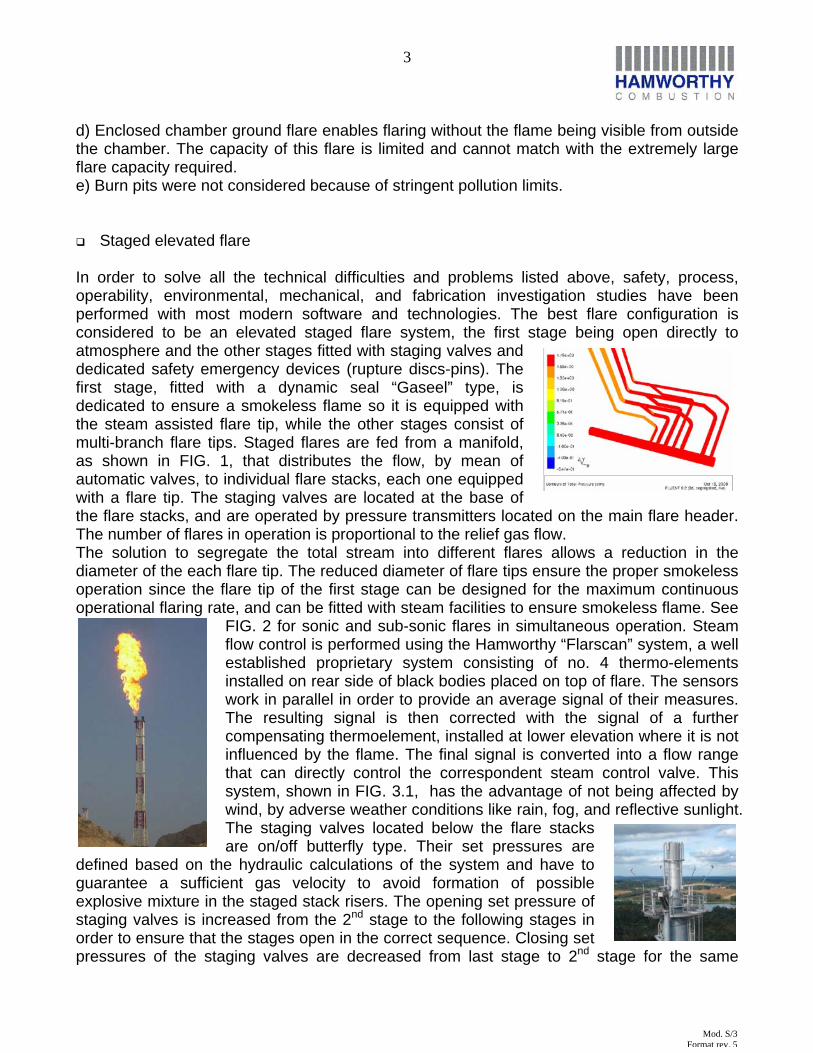
Staged elevated flare In order to solve all the technical difficulties and problems listed above, safety, process, operability, environmental, mechanical, and fabrication investigation studies have been performed with most modern software and technologies. The best flare configuration is considered to be an elevated staged flare system, the first stage being open directly to atmosphere and the other stages fitted with staging valves and dedicated safety emergency devices (rupture discs-pins). The first stage, fitted with a dynamic seal “Gaseel” type, is dedicated to ensure a smokeless flame so it is equipped with the steam assisted flare tip, while the other stages consist of multi-branch flare tips. Staged flares are fed from a manifold, as shown in FIG. 1, that distributes the flow, by mean of automatic valves, to individual flare stacks, each one equipped with a flare tip. The staging valves are located at the base of the flare stacks, and are operated by pressure transmitters located on the main flare header. The number of flares in operation is proportional to the relief gas flow. The solution to segregate the total stream into different flares allows a reduction in the diameter of the each flare tip. The reduced diameter of flare tips ensure the proper smokeless operation since the flare tip of the first stage can be designed for the maximum continuous operational flaring rate, and can be fitted with steam facilities to ensure smokeless flame. See
FIG. 2 for sonic and sub-sonic flares in simultaneous operation. Steam flow control is performed using the Hamworthy “Flarscan” system, a well established proprietary system consisting of no. 4 thermo-elements installed on rear side of black bodies placed on top of flare. The sensors work in parallel in order to provide an average signal of their measures. The resulting signal is then corrected with the signal of a further compensating thermoelement, installed at lower elevation where it is not influenced by the flame. The final signal is converted into a flow range that can directly control the correspondent steam control valve. This system, shown in FIG. 3.1, has the advantage of not being affected by wind, by adverse weather conditions like rain, fog, and reflective sunlight. The staging valves located below the flare stacks are on/off butterfly type. Their set pressures are
defined based on the hydraulic calculations of the system and have to guarantee a sufficient gas velocity to avoid formation of possible explosive mixture in the staged stack risers. The opening set pressure of staging valves is increased from the 2nd stage to the following stages in order to ensure that the stages open in the correct sequence. Closing set pressures of the staging valves are decreased from last stage to 2nd stage for the same

4
Mod. S/3 Format rev. 5
reason. With the proposed configuration, the last stage has been designed to be operated only in case of very large flaring rates resulting from an overall plant emergency. For safety and modularization reasons, each stage, and relevant flare tip has been designed to cover the extra rate caused by the abnormal situation of one staging valve failure. Flare system safety considerations require that staging valves will be provided with valve by-passes, each of them containing a fail-safe device like rupture disc or rupture pin. Flare staging curves and set pressures to correctly operate each stage are shown in the FIG. 4. The given curves are typical and may be adjusted based upon specific need like operating cases of the flare system, tolerance of the set point of selected rupture discs etc.. The size of the tip on the first stage has been designed to limit the gas exit velocity to 0.2 Mach at smokeless flow rate, and to 0.5 Mach at maximum flow in order to avoid vibrations. Exit sections of the other stages have been designed for exit velocity above 0.7 Mach. With a staged flare the exit velocity of the gas is averagely higher than a single flare, and the tip stages can be designed with a sonic approach. The sonic flare tip, that is shown in FIG. 3.2, has a design advantage of low flame emissivity due to more efficient combustion of flare gas and of shorter flame. As a consequence the heat radiation at grade results lower, and flare height has resulted in being 130 m. In addition, the dispersion at grade has been reduced due to the gas exit velocty being sustained across the complete range of operation. When the flare gas is discharged at high pressure, sonic flare tips also allow the designer to reduce header, sub-headers, risers and valves size, and hence cost. The main flare sub-headers and
flare risers have been sized for a maximum velocity of 0.5 Mach to limit the pressure drop across the valves and to attenuate the noise of the whole system. The limitation of the diameter of flare tips avoids flame front instability, and minimizes the potential for burnback and flashback. The capacity of each stage is larger than that of each previous stage. Minimum gas velocities in each stage have been designed in order to avoid formation of explosive mixtures inside the risers. The staging valves are pneumatically actuated and each actuator is designed to allow the fast opening of the valve This condition is
essential to avoid pressure build-up in main header, and thus in the plant. The valves are air-failure open, i.e. in case the air supply fails the valves open, it being prohibited to block the sub-headers, since this could cause an explosion due to inability to discharge the emergency flow. When one or more rupture discs break there is a sudden unbalancing of the forces causing a force of inertia induced by the dynamic load of the discharged gas. This force moves from the breaking area of the rupture disc up to the top of the flare, moving at sonic speed and inducing a further dynamic load on the inlet elbow, due to the change of direction of the flow. The same phenomenon also appears in lower intensity when the valves open, dependent on the time needed for full opening.

5
Mod. S/3 Format rev. 5
This calculation has been performed by a team of mechanical engineers designing the manifold to maximise the linearity of the flow pattern and optimise the system fluid-dynamics. In a case of valve opening failure the pressure increase causes the bursting disk to break, and the resulting shock wave dynamic load on inlet of the flare is higher than the above case. Additional countermeasures are taken by installation of a dampening system down stream the rupture disk. This has the aim: a) to reduce the width of the unbalanced forces acting on sub-header when disk breaks; b) to increase the time of the transition period just after disk bursting; c) to contain the horizontal shift of the piping. The energy of the dynamic loads is constant, but its distribution varies and its peaks are lower. The set pressure of the bursting disk is higher than opening set pressure of staging valves, so to avoid the bursting before the valve open; however it cannot be too high otherwise the pressure in the main header can rise very quickly with consequent danger of overpressure. Due to the large dimension of the valves they can take some seconds to fully open and close, so that the timing of their opening and closing may be anticipated in respect to their theoretical actuation pressure.
Conclusion The analysis to identify the best configuration for a flare adequate to manage the largest flaring rate of the world, coming from a single header confirms that the solution of a single large flare is neither practical nor convenient as it presents technical difficulties to secure the stability of the flame, the safety of the system and to guarantee the smokeless requirements. The proposed alternative consisting of a elevated staged flare has shown the advantages of a) limiting size of the flare tips which do not introduce flame stability issues; b) distributing properly the steam to the first stage, which will govern other emergency scenarios characterized by lower flow rate; c) guaranteeing a longer life cycle for the flare tips being normally closed and needing no continuous purging. This data, in conjunction with the fact that the design flaring rates are related to emergency scenarios that are very unlikely to occur have allowed to the designers to set the height of the flares at a reasonable, reliable, and referenced value. Captions FIG. 1 Pressure distribution along staging system located at stack base as result of simulation software; by-pass lines are fed by manifold independently from main sub-headers. FIG. 2 Photo of sonic and sub-sonic flares in operation simultaneous operation. FIG. 3 Photo of steam assisted (FUS) flare tip equipped with Hamworthy “Flarscan” system, and multi-branch (FSM MKIII) flare tip. FIG. 4 Diagram of staging system showing the relationship between flow rate and pressure. Literature cited 1 API RP 521 “Guide for Pressure-Relieving and Depressuring Systems” 2 API RP 537 “Flare Details for General Refinery and Petrochemical Service” 3 DEP SHELL 80.45.10.10 “Pressure relief, emergency depressuring, flare and vent systems”. 4 “An Album of Fluid Motion” – Van Dyke pictures 169/170/171