Flare Q+, Flare LR Q+, Flare, Flare Jr -...
31
Flare Q+, Flare Q+ LR, Flare, Flare Jr Operation Manual TMB 24/7 Technical Support US/Canada: +1 818.794.1286 Toll Free: 1 877.862.3833 (877.TMB.DUDE) Flare Q+ & Q+ LR UK: +44 (0)20.8574.9739 Toll Free: 0800.652.5418 e-mail: [email protected]
Transcript of Flare Q+, Flare LR Q+, Flare, Flare Jr -...
Flare Q+, Flare Q+ LR, Flare, Flare Jr
Operation Manual
TMB 24/7 Technical Support US/Canada: +1 818.794.1286 Toll Free: 1 877.862.3833 (877.TMB.DUDE) Flare Q+ & Q+ LR UK: +44 (0)20.8574.9739 Toll Free: 0800.652.5418 e-mail: [email protected]
Solaris Flare, Flare Q+, Flare Q+ LR, Flare Jr user manual version 11.1 022018 2
TABLE OF CONTENTS 1. INTRODUCTION .......................................................................................................................... 3
Product Overview ............................................................................................................... 3 Unpacking Instructions ...................................................................................................... 3 Power Requirements .......................................................................................................... 3 Frequency Setting .............................................................................................................. 3 Safety Instructions .............................................................................................................. 4 Technical Features ............................................................................................................. 4
2. SETUP ......................................................................................................................................... 5 Fuse Replacement ............................................................................................................. 5 Fixture Linking .................................................................................................................... 5 Power Linking – Flare Jr ..................................................................................................... 5 Setting up DMX Serial Data Link ........................................................................................ 6 Fixture Mounting / Rigging .................................................................................................. 6
3. OPERATING INSTRUCTIONS ................................................................................................... 7 Control Panel Navigation .................................................................................................... 7 Menu Map – Flare, Flare Q+, Flare Q+ LR ......................................................................... 8 Menu Map – Flare Jr .......................................................................................................... 9 Menu Function Description ............................................................................................... 10 Basic Mode ....................................................................................................................... 15 Strobe Modes ................................................................................................................... 16 Strobe-Only Mode ............................................................................................................ 17 RGB and RGBW Strobe Modes ........................................................................................ 18 Advanced Modes .............................................................................................................. 19 Pixel Locations – Flare, Flare Q+, Flare Q+ LR ................................................................ 20 Pixel Locations – Flare Jr ................................................................................................ 21 Advanced RGB Strobe DMX ............................................................................................ 21 Advanced RBGW Strobe DMX ......................................................................................... 22 Manual Function ............................................................................................................... 23 Color Output Calibration .................................................................................................... 25
4. APPENDIX ................................................................................................................................ 26
RDM Functionality ............................................................................................................ 26 General Maintenance ....................................................................................................... 26 Limited Warranty .............................................................................................................. 27 Return Procedure ............................................................................................................. 27 Technical Specifications – Flare ....................................................................................... 28 Technical Specifications – Flare Q+ .................................................................................. 29 Technical Specifications – Flare Jr ................................................................................... 30 Technical Specifications – Flare Q+ LR ........................................................................... 31
Important: Read this manual before powering or installing the unit. Follow the safety precautions listed herein. Observe all warnings in this manual and those printed on the unit.

Solaris Flare, Flare Q+, Flare Q+ LR, Flare Jr user manual version 11.1 022018 3
1. INTRODUCTION PRODUCT OVERVIEW Solaris Flare indoor LED fixtures are combination wash/strobe/blinders with over 1000 Watts of LED RGBW brightness, 58,000 lumens, instantaneous color mixing, and 1200Hz refresh rate for smooth on-camera dimming. Q+ Technology increases the brightness with practically no fan noise. Its “Theatre Mode” is effectively silent, yet still 8% brighter than the original Flare! One Solaris Flare LED fixture does the job of many conventional LED fixtures, saving setup time and labor. Just a few of the features include:
• Simultaneous color wash, strobe, and blinder in ONE fixture! – saves labor, time, space, cost • Instantaneous RGBW color mixing with 1200Hz refresh rate – smooth on-camera dimming • Pixel-map feature – up to 12 (Flare / Flare Q+ / Flare Q+ LR) or 4 (Flare Jr) discrete, individually-
controlled LED sections. • Optimized 36° beam width. 20°, 54°, and 70°options available. • cCSAus Listed (Flare Q+)
UNPACKING INSTRUCTIONS Upon receipt of the fixture, carefully unpack the carton and check the contents to ensure that all parts are present and in good condition. Notify the shipper immediately and retain packing material for inspection if any parts appear to be damaged from shipping or if the carton itself shows signs of mishandling. Save the carton and all packing materials. In the event that a fixture must be returned to the factory, it is important that the fixture be returned in the original factory box and packing.
POWER REQUIREMENTS Before powering the unit, make sure the line voltage is within the range of accepted voltages. This fixture accommodates 90-264VAC, 50/60Hz. All fixtures must be powered directly from a switched circuit and cannot be operated with a rheostat (variable resistor) or dimmer circuit, even if the rheostat or dimmer channel is used solely as a 0-100% switch. When powered up, Solaris performs a preprogrammed internal test. On initial power-up the factory default DMX address appears on the display screen and Solaris is ready for operation. After initial power-up, the last-saved DMX address will appear. FREQUENCY SETTING Depending on location, change the Default Frequency setting to match the mains power (e.g., US and Canada should be set at 60Hz). Proper frequency setting will ensure minimum amount of visible artifacts when using Solaris on camera.
Solaris Flare, Flare Q+, Flare Q+ LR, Flare Jr user manual version 11.1 022018 4
SAFETY INSTRUCTIONS
• Please keep this Operation Manual for future reference. If unit is sold to another user, make sure they also receive this instruction booklet.
• Ensure fixture is connected to proper voltage, and that line voltage is not higher than that stated on the fixture.
• Make sure there are no flammable materials close to the unit while operating. • Always disconnect from the power source before servicing or fuse replacement. Always use the fuse
specified in this manual. • Always use a safety cable when hanging fixture overhead. • Maximum ambient temperature (Ta) is 40°C (104°F). Do not operate fixture at temperatures above this
rating. • In the event of a serious operating problem, stop using the unit immediately. Repairs must be carried
out by trained, authorized personnel. Contact the nearest authorized technical assistance center. Only OEM spare parts should be used.
• Do not connect the device to a dimmer pack. • Make sure power cord is never crimped or damaged. • Never disconnect power cord by pulling or tugging on the cord. • Avoid direct eye exposure to the light source during operation. Caution! There are no user serviceable parts inside the unit. Do not open the housing or attempt any repairs yourself. In the unlikely event your unit may require service, please contact your distributor. Technical Features / Description
• Flare / Flare Q+: 96 10W RGBW Cree® LEDs, divided into 2, 3, 4, 6 or 12 pixels • Flare Jr: 32 10W RGBW Cree LEDs, divided into 1, 2, or 4 pixels • Flare Q+ LR: 108 10W RGBW Cree LEDs, divided into 1, 2, 3, 4, 6, or 12 pixels • Variable intensity control 0-100% in 8bit or 16bit control modes • Beam spread: 36° standard. Optional beam widths available: 20°, 54°, and 70°1 • Refresh rate: 1200HZ • Flash Duration control 0-650ms flashes per second • Flash Rate control 0-16.7Hz (50Hz) / 0-20Hz (60Hz) • Continuous blinder/wash effect • Flash intensity curve selection • User definable fades • LCD control panel display with four control buttons • RDM available in Flare RDM, Flare Jr, Flare Q+ and Flare Q+ LR (not available in early versions of
the original Flare)
1 Not available on all models
Please read these instructions carefully. This user guide contains important information about the installation, usage and maintenance of this fixture.
Solaris Flare, Flare Q+, Flare Q+ LR, Flare Jr user manual version 11.1 022018 5
2. SETUP
FUSE REPLACEMENT Flare, Flare Q+, Flare Q+ LR, and Flare Jr use a 12A 250V slow-blow fuse (5x20mm). To replace fuse:
1. With a screwdriver turn the fuse cap counter-clockwise to remove fuse cap with fuse. 2. Replace fuse attached to fuse cap. 3. Reinsert fuse cap with new fuse and tighten clockwise.
FIXTURE LINKING A DMX data link is needed to operate one or more fixtures via a DMX-512 lighting console. The combined number of channels required by all the fixtures on a DMX data link determines the number of fixtures the DMX data link can support. Important: Fixtures on a DMX data link must be daisy-chained in one single line. To comply with the EIA-485 standard, no more than 32 devices should be connected on one data link. Connecting more than 32 fixtures on one serial data link without the use of a DMX optically-isolated splitter may result in deterioration of the digital DMX signal. Maximum recommended DMX data link distance between fixtures: 984 ft. (300 meters). POWER LINKING (FLARE JR) The Flare Jr has Neutrik® PowerCon IN and THRU connections allowing power linking (daisy-chaining). Depending on the power provided, you should not exceed the power threshold. Max. 5 units 10-120V; max. 10 units 208-240V. A maximum 2 units of the Flare Q+ LR can be power linked.
Disconnect the power cord before replacing the fuse. Always replace with the correct fuse type.
Solaris Flare, Flare Q+, Flare Q+ LR, Flare Jr user manual version 11.1 022018 6
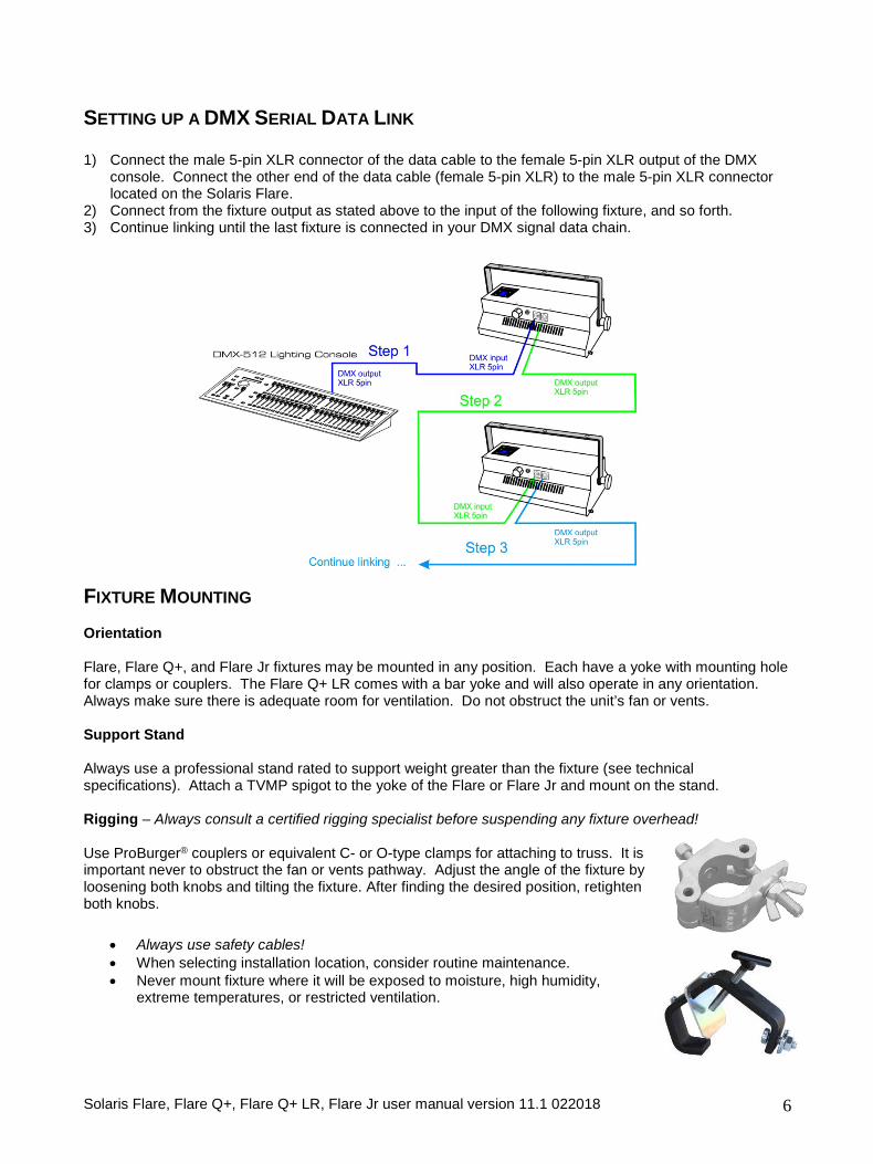
SETTING UP A DMX SERIAL DATA LINK 1) Connect the male 5-pin XLR connector of the data cable to the female 5-pin XLR output of the DMX
console. Connect the other end of the data cable (female 5-pin XLR) to the male 5-pin XLR connector located on the Solaris Flare.
2) Connect from the fixture output as stated above to the input of the following fixture, and so forth. 3) Continue linking until the last fixture is connected in your DMX signal data chain.
FIXTURE MOUNTING Orientation Flare, Flare Q+, and Flare Jr fixtures may be mounted in any position. Each have a yoke with mounting hole for clamps or couplers. The Flare Q+ LR comes with a bar yoke and will also operate in any orientation. Always make sure there is adequate room for ventilation. Do not obstruct the unit’s fan or vents. Support Stand Always use a professional stand rated to support weight greater than the fixture (see technical specifications). Attach a TVMP spigot to the yoke of the Flare or Flare Jr and mount on the stand. Rigging – Always consult a certified rigging specialist before suspending any fixture overhead! Use ProBurger® couplers or equivalent C- or O-type clamps for attaching to truss. It is important never to obstruct the fan or vents pathway. Adjust the angle of the fixture by loosening both knobs and tilting the fixture. After finding the desired position, retighten both knobs.
• Always use safety cables! • When selecting installation location, consider routine maintenance. • Never mount fixture where it will be exposed to moisture, high humidity,
extreme temperatures, or restricted ventilation.
Solaris Flare, Flare Q+, Flare Q+ LR, Flare Jr user manual version 11.1 022018 7
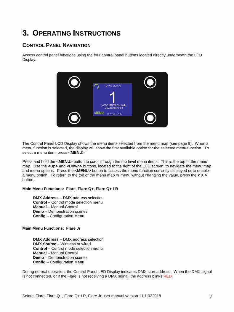
3. OPERATING INSTRUCTIONS CONTROL PANEL NAVIGATION Access control panel functions using the four control panel buttons located directly underneath the LCD Display.
The Control Panel LCD Display shows the menu items selected from the menu map (see page 9). When a menu function is selected, the display will show the first available option for the selected menu function. To select a menu item, press <MENU>. Press and hold the <MENU> button to scroll through the top level menu items. This is the top of the menu map. Use the <Up> and <Down> buttons, located to the right of the LCD screen, to navigate the menu map and menu options. Press the <MENU> button to access the menu function currently displayed or to enable a menu option. To return to the top of the menu map or menu without changing the value, press the < X > button. Main Menu Functions: Flare, Flare Q+, Flare Q+ LR
DMX Address – DMX address selection Control – Control mode selection menu Manual – Manual Control Demo – Demonstration scenes Config – Configuration Menu
Main Menu Functions: Flare Jr
DMX Address – DMX address selection DMX Source – Wireless or wired Control – Control mode selection menu Manual – Manual Control Demo – Demonstration scenes Config – Configuration Menu
During normal operation, the Control Panel LED Display indicates DMX start address. When the DMX signal is not connected, or if the Flare is not receiving a DMX signal, the address blinks RED.
Solaris Flare, Flare Q+, Flare Q+ LR, Flare Jr user manual version 11.1 022018 8
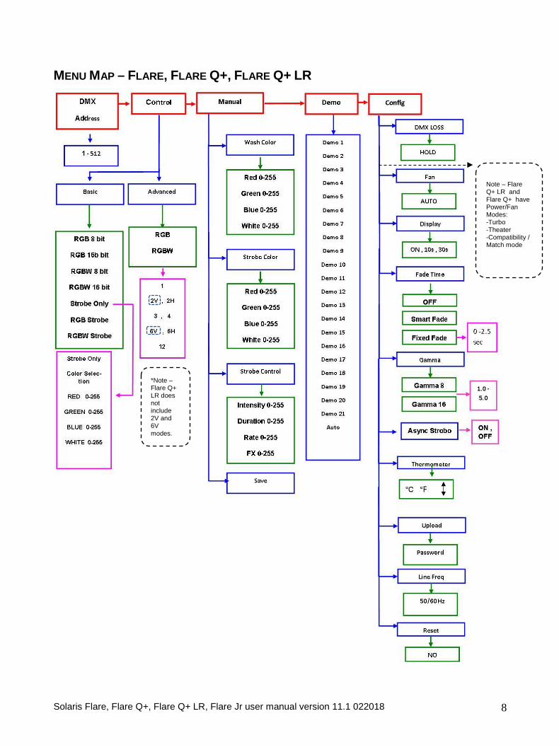
MENU MAP – FLARE, FLARE Q+, FLARE Q+ LR
*Note – Flare Q+ LR does not include 2V and 6V modes.
Note – Flare Q+ LR and Flare Q+ have Power/Fan Modes: -Turbo -Theater -Compatibility / Match mode
Solaris Flare, Flare Q+, Flare Q+ LR, Flare Jr user manual version 11.1 022018 9
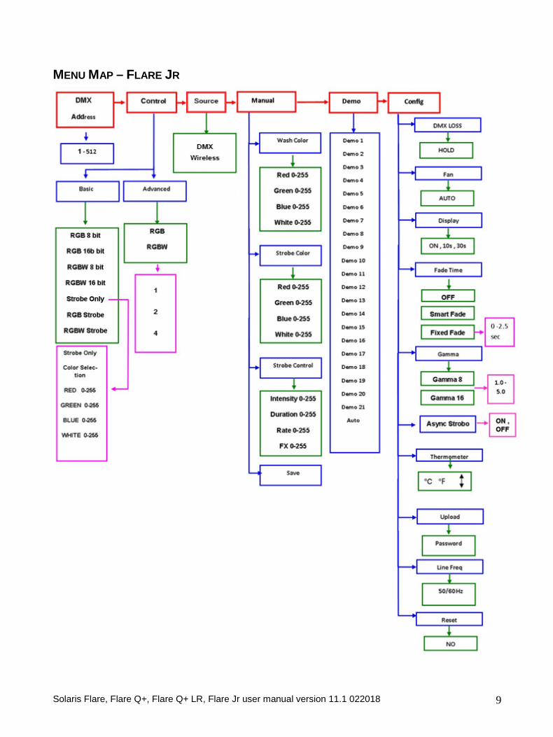
MENU MAP – FLARE JR
Solaris Flare, Flare Q+, Flare Q+ LR, Flare Jr user manual version 11.1 022018 10
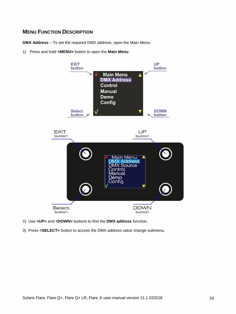
MENU FUNCTION DESCRIPTION DMX Address – To set the required DMX address, open the Main Menu: 1) Press and hold <MENU> button to open the Main Menu.
2) Use <UP> and <DOWN> buttons to find the DMX address function. 3) Press <SELECT> button to access the DMX address value change submenu.
Solaris Flare, Flare Q+, Flare Q+ LR, Flare Jr user manual version 11.1 022018 11
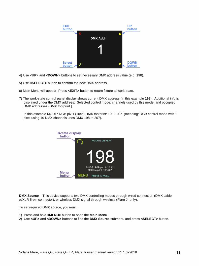
4) Use <UP> and <DOWN> buttons to set necessary DMX address value (e.g. 198). 5) Use <SELECT> button to confirm the new DMX address. 6) Main Menu will appear. Press <EXIT> button to return fixture at work-state. 7) The work-state control panel display shows current DMX address (in this example 198). Additional info is
displayed under the DMX address: Selected control mode, channels used by this mode, and occupied DMX addresses (DMX footprint.)
In this example MODE: RGB pix:1 (10ch) DMX footprint: 198 - 207 (meaning: RGB control mode with 1 pixel using 10 DMX channels uses DMX 198 to 207).
DMX Source – This device supports two DMX controlling modes through wired connection (DMX cable w/XLR 5-pin connector), or wireless DMX signal through wireless (Flare Jr only). To set required DMX source, you must: 1) Press and hold <MENU> button to open the Main Menu. 2) Use <UP> and <DOWN> buttons to find the DMX Source submenu and press <SELECT> button.
Solaris Flare, Flare Q+, Flare Q+ LR, Flare Jr user manual version 11.1 022018 12
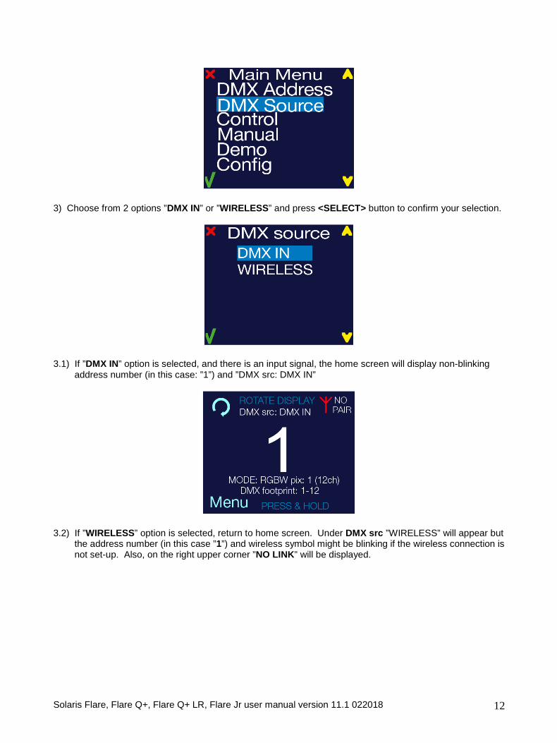
3) Choose from 2 options ”DMX IN” or ”WIRELESS” and press <SELECT> button to confirm your selection.
3.1) If ”DMX IN” option is selected, and there is an input signal, the home screen will display non-blinking address number (in this case: ”1”) and ”DMX src: DMX IN”
3.2) If ”WIRELESS” option is selected, return to home screen. Under DMX src ”WIRELESS” will appear but
the address number (in this case ”1”) and wireless symbol might be blinking if the wireless connection is not set-up. Also, on the right upper corner ”NO LINK” will be displayed.
Solaris Flare, Flare Q+, Flare Q+ LR, Flare Jr user manual version 11.1 022018 13
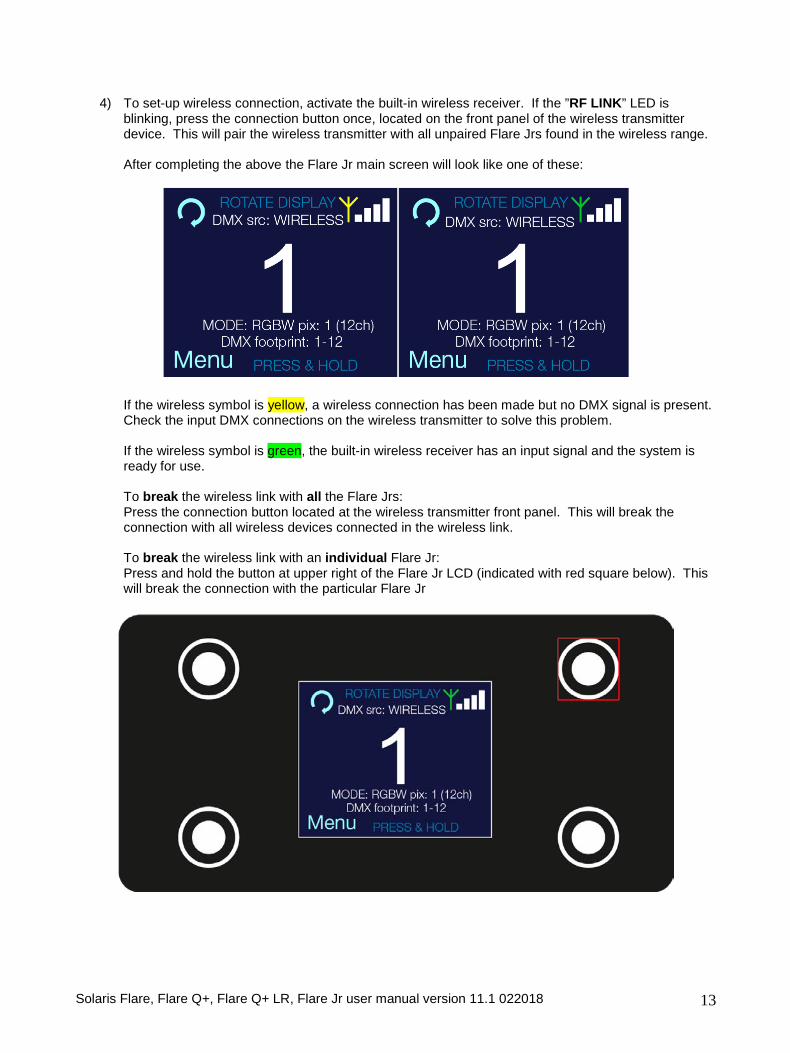
4) To set-up wireless connection, activate the built-in wireless receiver. If the ”RF LINK” LED is blinking, press the connection button once, located on the front panel of the wireless transmitter device. This will pair the wireless transmitter with all unpaired Flare Jrs found in the wireless range.
After completing the above the Flare Jr main screen will look like one of these:
If the wireless symbol is yellow, a wireless connection has been made but no DMX signal is present. Check the input DMX connections on the wireless transmitter to solve this problem.
If the wireless symbol is green, the built-in wireless receiver has an input signal and the system is ready for use.
To break the wireless link with all the Flare Jrs: Press the connection button located at the wireless transmitter front panel. This will break the connection with all wireless devices connected in the wireless link.
To break the wireless link with an individual Flare Jr: Press and hold the button at upper right of the Flare Jr LCD (indicated with red square below). This will break the connection with the particular Flare Jr
Solaris Flare, Flare Q+, Flare Q+ LR, Flare Jr user manual version 11.1 022018 14
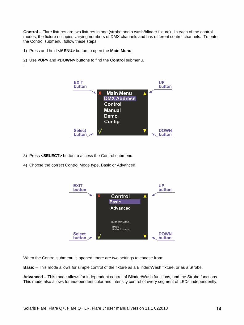
Control – Flare fixtures are two fixtures in one (strobe and a wash/blinder fixture). In each of the control modes, the fixture occupies varying numbers of DMX channels and has different control channels. To enter the Control submenu, follow these steps: 1) Press and hold <MENU> button to open the Main Menu. 2) Use <UP> and <DOWN> buttons to find the Control submenu. .
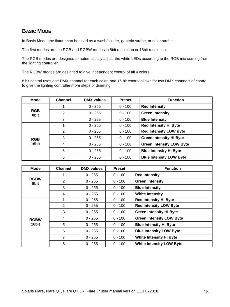
3) Press <SELECT> button to access the Control submenu. 4) Choose the correct Control Mode type, Basic or Advanced.
When the Control submenu is opened, there are two settings to choose from: Basic – This mode allows for simple control of the fixture as a Blinder/Wash fixture, or as a Strobe. Advanced – This mode allows for independent control of Blinder/Wash functions, and the Strobe functions. This mode also allows for independent color and intensity control of every segment of LEDs independently.
Solaris Flare, Flare Q+, Flare Q+ LR, Flare Jr user manual version 11.1 022018 15
BASIC MODE
In Basic Mode, the fixture can be used as a wash/blinder, generic strobe, or color strobe. The first modes are the RGB and RGBW modes in 8bit resolution or 16bit resolution. The RGB modes are designed to automatically adjust the white LEDs according to the RGB mix coming from the lighting controller. The RGBW modes are designed to give independent control of all 4 colors. 8 bit control uses one DMX channel for each color, and 16 bit control allows for two DMX channels of control to give the lighting controller more steps of dimming.
Mode Channel DMX values Preset Function
RGB 8bit
1 0 - 255 0 - 100 Red Intensity 2 0 - 255 0 - 100 Green Intensity 3 0 - 255 0 - 100 Blue Intensity
RGB 16bit
1 0 - 255 0 - 100 Red Intensity HI Byte 2 0 - 255 0 - 100 Red Intensity LOW Byte 3 0 - 255 0 - 100 Green Intensity HI Byte 4 0 - 255 0 - 100 Green Intensity LOW Byte 5 0 - 255 0 - 100 Blue Intensity HI Byte 6 0 - 255 0 - 100 Blue Intensity LOW Byte
Mode Channel DMX values Preset Function
RGBW 8bit
1 0 - 255 0 - 100 Red Intensity 2 0 - 255 0 - 100 Green Intensity 3 0 - 255 0 - 100 Blue Intensity
4 0 - 255 0 - 100 White Intensity
RGBW 16bit
1 0 - 255 0 - 100 Red Intensity HI Byte 2 0 - 255 0 - 100 Red Intensity LOW Byte 3 0 - 255 0 - 100 Green Intensity HI Byte 4 0 - 255 0 - 100 Green Intensity LOW Byte 5 0 - 255 0 - 100 Blue Intensity HI Byte 6 0 - 255 0 - 100 Blue Intensity LOW Byte 7 0 - 255 0 - 100 White Intensity HI Byte 8 0 - 255 0 - 100 White Intensity LOW Byte
Solaris Flare, Flare Q+, Flare Q+ LR, Flare Jr user manual version 11.1 022018 16
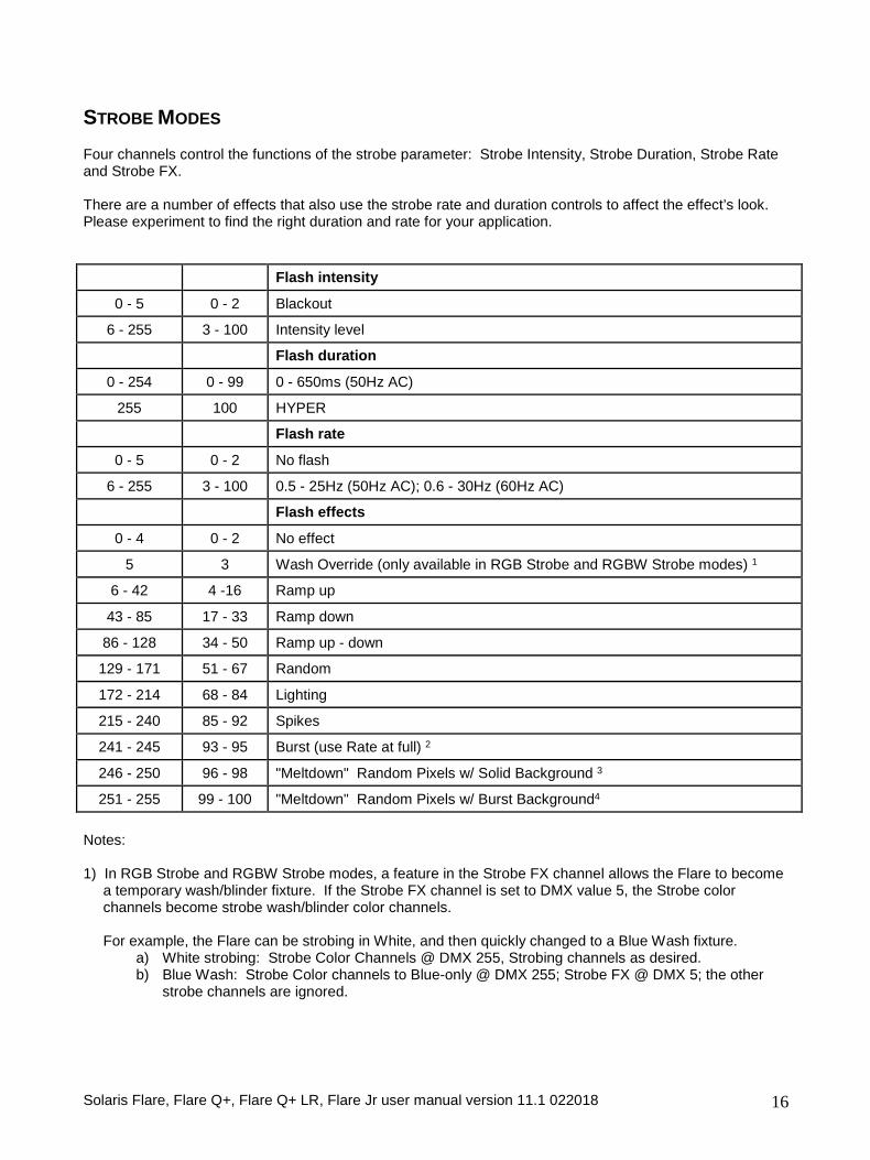
STROBE MODES Four channels control the functions of the strobe parameter: Strobe Intensity, Strobe Duration, Strobe Rate and Strobe FX. There are a number of effects that also use the strobe rate and duration controls to affect the effect’s look. Please experiment to find the right duration and rate for your application.
Flash intensity
0 - 5 0 - 2 Blackout
6 - 255 3 - 100 Intensity level
Flash duration
0 - 254 0 - 99 0 - 650ms (50Hz AC)
255 100 HYPER
Flash rate
0 - 5 0 - 2 No flash
6 - 255 3 - 100 0.5 - 25Hz (50Hz AC); 0.6 - 30Hz (60Hz AC)
Flash effects
0 - 4 0 - 2 No effect
5 3 Wash Override (only available in RGB Strobe and RGBW Strobe modes) 1
6 - 42 4 -16 Ramp up
43 - 85 17 - 33 Ramp down
86 - 128 34 - 50 Ramp up - down
129 - 171 51 - 67 Random
172 - 214 68 - 84 Lighting
215 - 240 85 - 92 Spikes
241 - 245 93 - 95 Burst (use Rate at full) 2
246 - 250 96 - 98 "Meltdown" Random Pixels w/ Solid Background 3
251 - 255 99 - 100 "Meltdown" Random Pixels w/ Burst Background4 Notes: 1) In RGB Strobe and RGBW Strobe modes, a feature in the Strobe FX channel allows the Flare to become
a temporary wash/blinder fixture. If the Strobe FX channel is set to DMX value 5, the Strobe color channels become strobe wash/blinder color channels.
For example, the Flare can be strobing in White, and then quickly changed to a Blue Wash fixture.
a) White strobing: Strobe Color Channels @ DMX 255, Strobing channels as desired. b) Blue Wash: Strobe Color channels to Blue-only @ DMX 255; Strobe FX @ DMX 5; the other
strobe channels are ignored.
Solaris Flare, Flare Q+, Flare Q+ LR, Flare Jr user manual version 11.1 022018 17
2) When burst is activated, use the rate channel at FULL to access a hyper-speed strobe 3) When Meltdown with Solid background is active, the Strobe Color determines the random pixel color, and
the background color is determined by the pixel colors after the strobe fx channels. There is no background color when in RGB Strobe and RGBW Strobe mode. The background pixels are solid-on in this mode. The foreground strobe is randomized, not achievable in any other mode, and is difficult to reproduce with most DMX controllers at this rate.
4) When Meltdown with Burst background is active, the Strobe Color determines the random pixel color, and
the background color is determined by the pixel colors after the strobe fx channels. There is no background color when in RGB Strobe and RGBW Strobe mode. The background pixels run at burst speed in this mode. The foreground strobe is randomized which is not achievable in any other mode, and is difficult to reproduce with most DMX controllers at this rate.
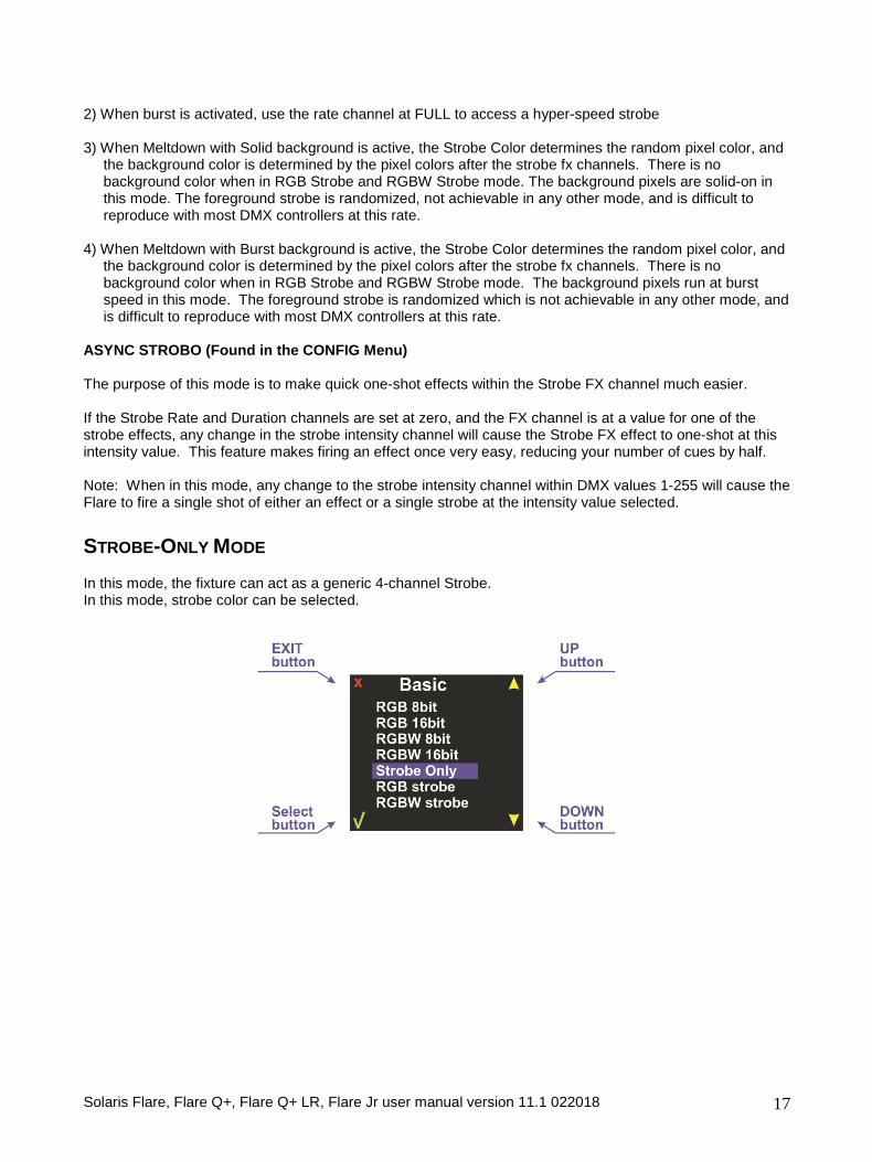
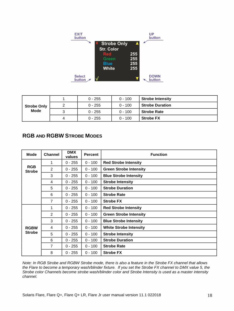
ASYNC STROBO (Found in the CONFIG Menu) The purpose of this mode is to make quick one-shot effects within the Strobe FX channel much easier. If the Strobe Rate and Duration channels are set at zero, and the FX channel is at a value for one of the strobe effects, any change in the strobe intensity channel will cause the Strobe FX effect to one-shot at this intensity value. This feature makes firing an effect once very easy, reducing your number of cues by half. Note: When in this mode, any change to the strobe intensity channel within DMX values 1-255 will cause the Flare to fire a single shot of either an effect or a single strobe at the intensity value selected. STROBE-ONLY MODE In this mode, the fixture can act as a generic 4-channel Strobe. In this mode, strobe color can be selected.
Solaris Flare, Flare Q+, Flare Q+ LR, Flare Jr user manual version 11.1 022018 18
Strobe Only Mode
1 0 - 255 0 - 100 Strobe Intensity 2 0 - 255 0 - 100 Strobe Duration 3 0 - 255 0 - 100 Strobe Rate 4 0 - 255 0 - 100 Strobe FX
RGB AND RGBW STROBE MODES
Mode Channel DMX values Percent Function
RGB Strobe
1 0 - 255 0 - 100 Red Strobe Intensity 2 0 - 255 0 - 100 Green Strobe Intensity 3 0 - 255 0 - 100 Blue Strobe Intensity
4 0 - 255 0 - 100 Strobe Intensity 5 0 - 255 0 - 100 Strobe Duration 6 0 - 255 0 - 100 Strobe Rate 7 0 - 255 0 - 100 Strobe FX
RGBW Strobe
1 0 - 255 0 - 100 Red Strobe Intensity 2 0 - 255 0 - 100 Green Strobe Intensity 3 0 - 255 0 - 100 Blue Strobe Intensity 4 0 - 255 0 - 100 White Strobe Intensity 5 0 - 255 0 - 100 Strobe Intensity 6 0 - 255 0 - 100 Strobe Duration 7 0 - 255 0 - 100 Strobe Rate 8 0 - 255 0 - 100 Strobe FX
Note: In RGB Strobe and RGBW Strobe mode, there is also a feature in the Strobe FX channel that allows the Flare to become a temporary wash/blinder fixture. If you set the Strobe FX channel to DMX value 5, the Strobe color Channels become strobe wash/blinder color and Strobe Intensity is used as a master intensity channel.
Solaris Flare, Flare Q+, Flare Q+ LR, Flare Jr user manual version 11.1 022018 19
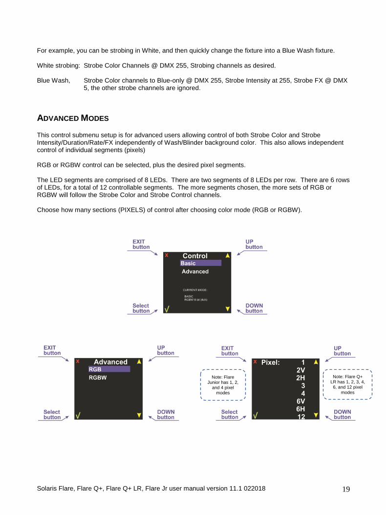
For example, you can be strobing in White, and then quickly change the fixture into a Blue Wash fixture. White strobing: Strobe Color Channels @ DMX 255, Strobing channels as desired. Blue Wash, Strobe Color channels to Blue-only @ DMX 255, Strobe Intensity at 255, Strobe FX @ DMX
5, the other strobe channels are ignored. ADVANCED MODES This control submenu setup is for advanced users allowing control of both Strobe Color and Strobe Intensity/Duration/Rate/FX independently of Wash/Blinder background color. This also allows independent control of individual segments (pixels) RGB or RGBW control can be selected, plus the desired pixel segments. The LED segments are comprised of 8 LEDs. There are two segments of 8 LEDs per row. There are 6 rows of LEDs, for a total of 12 controllable segments. The more segments chosen, the more sets of RGB or RGBW will follow the Strobe Color and Strobe Control channels. Choose how many sections (PIXELS) of control after choosing color mode (RGB or RGBW).
Note: Flare Q+ LR has 1, 2, 3, 4, 6, and 12 pixel
modes
Note: Flare Junior has 1, 2,
and 4 pixel modes
Solaris Flare, Flare Q+, Flare Q+ LR, Flare Jr user manual version 11.1 022018 20
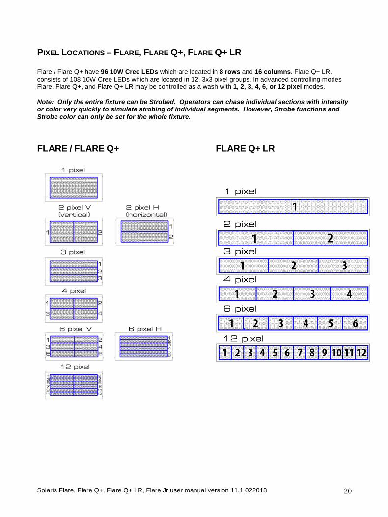
PIXEL LOCATIONS – FLARE, FLARE Q+, FLARE Q+ LR Flare / Flare Q+ have 96 10W Cree LEDs which are located in 8 rows and 16 columns. Flare Q+ LR. consists of 108 10W Cree LEDs which are located in 12, 3x3 pixel groups. In advanced controlling modes Flare, Flare Q+, and Flare Q+ LR may be controlled as a wash with 1, 2, 3, 4, 6, or 12 pixel modes. Note: Only the entire fixture can be Strobed. Operators can chase individual sections with intensity or color very quickly to simulate strobing of individual segments. However, Strobe functions and Strobe color can only be set for the whole fixture. FLARE / FLARE Q+ FLARE Q+ LR
Solaris Flare, Flare Q+, Flare Q+ LR, Flare Jr user manual version 11.1 022018 21
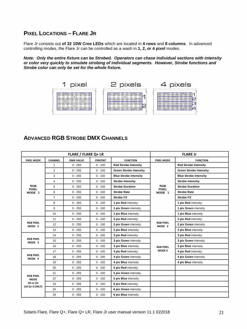
PIXEL LOCATIONS – FLARE JR Flare Jr consists out of 32 10W Cree LEDs which are located in 4 rows and 8 columns. In advanced controlling modes, the Flare Jr can be controlled as a wash in 1, 2, or 4 pixel modes. Note: Only the entire fixture can be Strobed. Operators can chase individual sections with intensity or color very quickly to simulate strobing of individual segments. However, Strobe functions and Strobe color can only be set for the whole fixture.
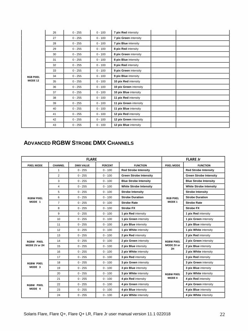
ADVANCED RGB STROBE DMX CHANNELS
FLARE / FLARE Q+ LR FLARE Jr
PIXEL MODE CHANNEL DMX VALUE PERCENT FUNCTION PIXEL MODE FUNCTION
RGB PIXEL
MODE 1
1 0 - 255 0 - 100 Red Strobe Intensity
RGB PIXEL
MODE 1
Red Strobe Intensity
2 0 - 255 0 - 100 Green Strobe Intensity Green Strobe Intensity
3 0 - 255 0 - 100 Blue Strobe Intensity Blue Strobe Intensity
4 0 - 255 0 - 100 Strobe Intensity Strobe Intensity
5 0 - 255 0 - 100 Strobe Duration Strobe Duration
6 0 - 255 0 - 100 Strobe Rate Strobe Rate
7 0 - 255 0 - 100 Strobe FX Strobe FX
8 0 - 255 0 - 100 1 pix Red intensity 1 pix Red intensity
9 0 - 255 0 - 100 1 pix Green intensity 1 pix Green intensity
10 0 - 255 0 - 100 1 pix Blue intensity 1 pix Blue intensity
RGB PIXEL MODE 2
11 0 - 255 0 - 100 2 pix Red intensity RGB PIXEL MODE 2
2 pix Red intensity
12 0 - 255 0 - 100 2 pix Green intensity 2 pix Green intensity
13 0 - 255 0 - 100 2 pix Blue intensity 2 pix Blue intensity
RGB PIXEL MODE 3
14 0 - 255 0 - 100 3 pix Red intensity
RGB PIXEL MODE 4
3 pix Red intensity
15 0 - 255 0 - 100 3 pix Green intensity 3 pix Green intensity
16 0 - 255 0 - 100 3 pix Blue intensity 3 pix Blue intensity
RGB PIXEL MODE 4
17 0 - 255 0 - 100 4 pix Red intensity 4 pix Red intensity
18 0 - 255 0 - 100 4 pix Green intensity 4 pix Green intensity
19 0 - 255 0 - 100 4 pix Blue intensity 4 pix Blue intensity
RGB PIXEL MODE
6H or 6V (LR Q+ 6 ONLY)
20 0 - 255 0 - 100 5 pix Red intensity
21 0 - 255 0 - 100 5 pix Green intensity
22 0 - 255 0 - 100 5 pix Blue intensity
23 0 - 255 0 - 100 6 pix Red intensity
24 0 - 255 0 - 100 6 pix Green intensity
25 0 - 255 0 - 100 6 pix Blue intensity
Solaris Flare, Flare Q+, Flare Q+ LR, Flare Jr user manual version 11.1 022018 22
RGB PIXEL MODE 12
26 0 - 255 0 - 100 7 pix Red intensity
27 0 - 255 0 - 100 7 pix Green intensity
28 0 - 255 0 - 100 7 pix Blue intensity
29 0 - 255 0 - 100 8 pix Red intensity
30 0 - 255 0 - 100 8 pix Green intensity
31 0 - 255 0 - 100 8 pix Blue intensity
32 0 - 255 0 - 100 9 pix Red intensity
33 0 - 255 0 - 100 9 pix Green intensity
34 0 - 255 0 - 100 9 pix Blue intensity
35 0 - 255 0 - 100 10 pix Red intensity
36 0 - 255 0 - 100 10 pix Green intensity
37 0 - 255 0 - 100 10 pix Blue intensity
38 0 - 255 0 - 100 11 pix Red intensity
39 0 - 255 0 - 100 11 pix Green intensity
40 0 - 255 0 - 100 11 pix Blue intensity
41 0 - 255 0 - 100 12 pix Red intensity
42 0 - 255 0 - 100 12 pix Green intensity
43 0 - 255 0 - 100 12 pix Blue intensity
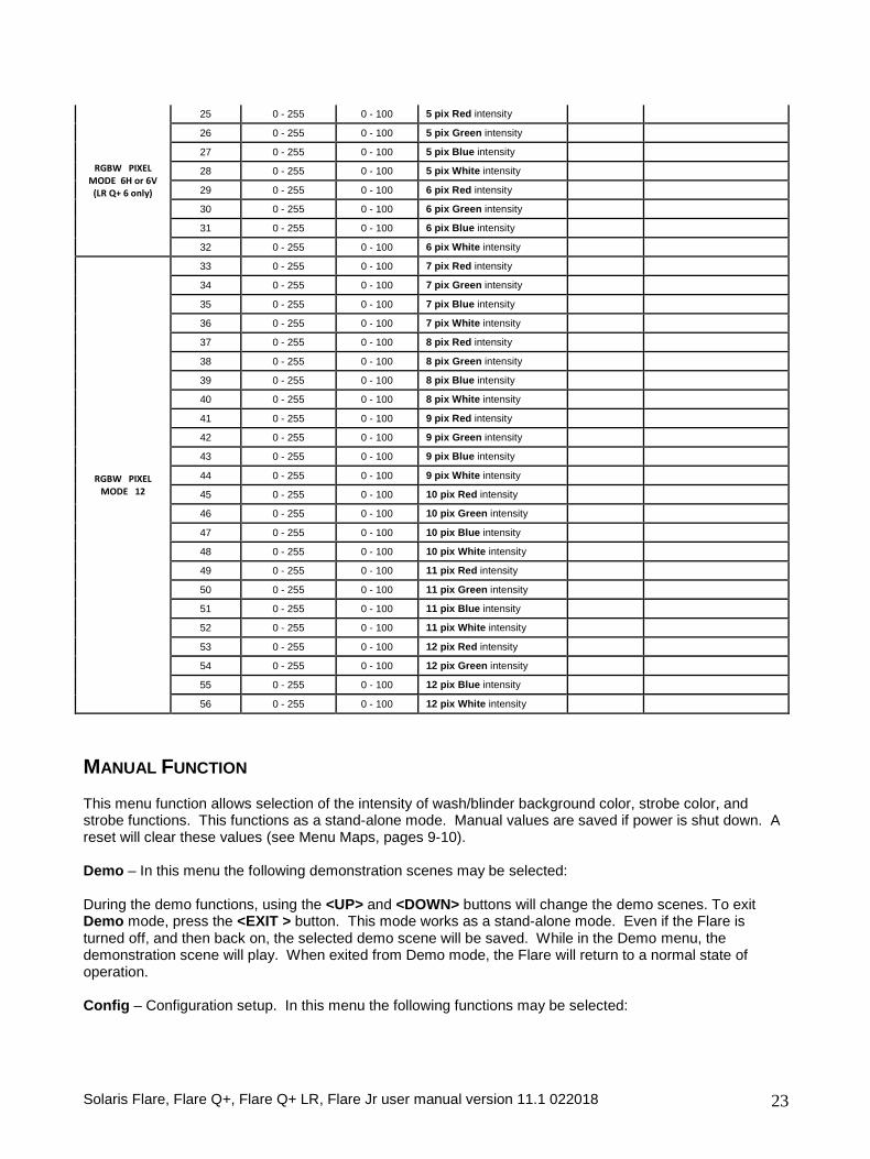
ADVANCED RGBW STROBE DMX CHANNELS
FLARE FLARE Jr
PIXEL MODE CHANNEL DMX VALUE PERCENT FUNCTION PIXEL MODE FUNCTION
RGBW PIXEL MODE 1
1 0 - 255 0 - 100 Red Strobe Intensity
RGB PIXEL MODE 1
Red Strobe Intensity
2 0 - 255 0 - 100 Green Strobe Intensity Green Strobe Intensity
3 0 - 255 0 - 100 Blue Strobe Intensity Blue Strobe Intensity
4 0 - 255 0 - 100 White Strobe Intensity White Strobe Intensity
5 0 - 255 0 - 100 Strobe Intensity Strobe Intensity
6 0 - 255 0 - 100 Strobe Duration Strobe Duration
7 0 - 255 0 - 100 Strobe Rate Strobe Rate
8 0 - 255 0 - 100 Strobe FX Strobe FX
9 0 - 255 0 - 100 1 pix Red intensity 1 pix Red intensity
10 0 - 255 0 - 100 1 pix Green intensity 1 pix Green intensity
11 0 - 255 0 - 100 1 pix Blue intensity 1 pix Blue intensity
12 0 - 255 0 - 100 1 pix White intensity 1 pix White intensity
RGBW PIXEL MODE 2V or 2H
13 0 - 255 0 - 100 2 pix Red intensity
RGBW PIXEL MODE 2V or
2H
2 pix Red intensity
14 0 - 255 0 - 100 2 pix Green intensity 2 pix Green intensity
15 0 - 255 0 - 100 2 pix Blue intensity 2 pix Blue intensity
16 0 - 255 0 - 100 2 pix White intensity 2 pix White intensity
RGBW PIXEL MODE 3
17 0 - 255 0 - 100 3 pix Red intensity
RGBW PIXEL MODE 4
3 pix Red intensity
18 0 - 255 0 - 100 3 pix Green intensity 3 pix Green intensity
19 0 - 255 0 - 100 3 pix Blue intensity 3 pix Blue intensity
20 0 - 255 0 - 100 3 pix White intensity 3 pix White intensity
RGBW PIXEL MODE 4
21 0 - 255 0 - 100 4 pix Red intensity 4 pix Red intensity
22 0 - 255 0 - 100 4 pix Green intensity 4 pix Green intensity
23 0 - 255 0 - 100 4 pix Blue intensity 4 pix Blue intensity
24 0 - 255 0 - 100 4 pix White intensity 4 pix White intensity
Solaris Flare, Flare Q+, Flare Q+ LR, Flare Jr user manual version 11.1 022018 23
RGBW PIXEL MODE 6H or 6V
(LR Q+ 6 only)
25 0 - 255 0 - 100 5 pix Red intensity
26 0 - 255 0 - 100 5 pix Green intensity
27 0 - 255 0 - 100 5 pix Blue intensity
28 0 - 255 0 - 100 5 pix White intensity
29 0 - 255 0 - 100 6 pix Red intensity
30 0 - 255 0 - 100 6 pix Green intensity
31 0 - 255 0 - 100 6 pix Blue intensity
32 0 - 255 0 - 100 6 pix White intensity
RGBW PIXEL MODE 12
33 0 - 255 0 - 100 7 pix Red intensity
34 0 - 255 0 - 100 7 pix Green intensity
35 0 - 255 0 - 100 7 pix Blue intensity
36 0 - 255 0 - 100 7 pix White intensity
37 0 - 255 0 - 100 8 pix Red intensity
38 0 - 255 0 - 100 8 pix Green intensity
39 0 - 255 0 - 100 8 pix Blue intensity
40 0 - 255 0 - 100 8 pix White intensity
41 0 - 255 0 - 100 9 pix Red intensity
42 0 - 255 0 - 100 9 pix Green intensity
43 0 - 255 0 - 100 9 pix Blue intensity
44 0 - 255 0 - 100 9 pix White intensity
45 0 - 255 0 - 100 10 pix Red intensity
46 0 - 255 0 - 100 10 pix Green intensity
47 0 - 255 0 - 100 10 pix Blue intensity
48 0 - 255 0 - 100 10 pix White intensity
49 0 - 255 0 - 100 11 pix Red intensity
50 0 - 255 0 - 100 11 pix Green intensity
51 0 - 255 0 - 100 11 pix Blue intensity
52 0 - 255 0 - 100 11 pix White intensity
53 0 - 255 0 - 100 12 pix Red intensity
54 0 - 255 0 - 100 12 pix Green intensity
55 0 - 255 0 - 100 12 pix Blue intensity
56 0 - 255 0 - 100 12 pix White intensity
MANUAL FUNCTION This menu function allows selection of the intensity of wash/blinder background color, strobe color, and strobe functions. This functions as a stand-alone mode. Manual values are saved if power is shut down. A reset will clear these values (see Menu Maps, pages 9-10). Demo – In this menu the following demonstration scenes may be selected: During the demo functions, using the <UP> and <DOWN> buttons will change the demo scenes. To exit Demo mode, press the <EXIT > button. This mode works as a stand-alone mode. Even if the Flare is turned off, and then back on, the selected demo scene will be saved. While in the Demo menu, the demonstration scene will play. When exited from Demo mode, the Flare will return to a normal state of operation. Config – Configuration setup. In this menu the following functions may be selected:
Solaris Flare, Flare Q+, Flare Q+ LR, Flare Jr user manual version 11.1 022018 24
DMX LOSS – Select desired function should the Flare lose DMX signal: HOLD – Hold the last received DMX values when DMX signal is lost OFF – Do not hold the last received DMX values when DMX signal is lost. Also stops light output. Fan – Cooling Fan: AUTO – Fan speed is automatically controlled by the Flare and will adjust according to temperatures at normal operating levels.
ON – Fan cooling always is turned on. Note: Flare Q+ and Flare Q+ LR have a Power/Fan menu category. In this menu you have three modes:
• Turbo Mode – Full Power, full fans when needed • Theater Mode – Reduced power and fan noise • Match/Compatibility – Reduced power and max. fan speed to match first generation Flare output.
Display – Automatic power on/off: ON – Control display is turned on. 10s – Control display is turned off after 10 seconds of inactivity. 30s – Control display is turned off after 30 seconds of inactivity. Thermometer – Internal temperature gauge: The built-in thermometer tracks internal operating temperature. Pressing the <UP> and <DOWN> buttons selects degrees Celsius or Fahrenheit. Fade Time – Fade time setup. The operator can set the way the Flare reacts to changing DMX values. This is designed to allow the light output of the Flare to react as smoothly as possible when crossfading DMX values. OFF – The Flare will not change the smoothness of crossfading of values coming from the lighting controller. Smart Fade – The Flare will attempt to add smoothness to crossfading DMX values coming from the lighting controller, but will also allow for very quick change of values where smoothness is not applicable. Fixed Fade – The fade time for any change in DMX values can be set manually. The timing values can be set from 0.01 to 2.50 seconds. Use the <Up> and <Down> buttons to change these values. Gamma – Gamma correction curve selection. This sets direct relation between AC current to the LEDs and the DMX value. The lower the value, the dimming curve and steps of intensity will be more noticeable at the bottom of the DMX range. The higher the value, the smoother the bottom end of the curve will be where the human eye detects more subtle changes. Gamma 8 – 8-bit rate Gamma correction setup. Color dimming curve values can be set from 1.0 to 5.0. The default value is 3.0 Gamma 16 – 16-bit rate Gamma correction setup. Each color dimming curve values from 1.0 to 5.0. The default value is 1.0 Async Strobo – This special mode allows for fast programming and “one-hit” effects (see Strobe Modes section of Manual). Default is OFF, turn ON to activate. Upload – Upload software. Designed to cross-load software from one Flare to others in the DMX data chain. This should not be used when other fixture types are in the data chain. Use of this function will be prompted by Password. The password is 111.
Solaris Flare, Flare Q+, Flare Q+ LR, Flare Jr user manual version 11.1 022018 25
Line Freq – Line Frequency. Allows adjustment of Flare input power frequency to match local source power for minimum visual artifacts on camera. The setting depends on region of use and power source. There are two options: 50Hz and 60Hz. Use the <UP> and <DOWN> buttons to change these values. Reset – Set factory defaults. Two options: NO and YES. Use the <UP> and <DOWN> buttons to change these values. Source (Flare Jr Only) – DMX IN – Wired XLR connection Wireless – Optional wireless configuration FLARE v8.9 and FLARE RDM v9.73 LED Color Output Calibration In some cases, different versions and vintages of Flares will exhibit slightly different levels of output of Red, Green, Blue, and White. The method below describes the best way to match Flare colors and output to achieve the most consistent results possible. Tools required: DMX Source Lux meter (for ideal results) or two sheets of white paper. Setting the units up to be calibrated: To enable calibration mode, first address the units to be calibrated to DMX “511”. A password prompt will appear. Change the value on screen to “88” and hit the ENTER/checkmark button. Enter the “CONFIG” menu and scroll down to “ENGINEER”. In the Engineer menu select “XML” and choose “CALIBRATED”. Go to the “CALIBRATE” menu option to access the calibration controls. This allows the operator to set intensity for each color and adjust each color hue. Intensity of each color adjusts the output of each color. Red hue is changed by adding green color. Green hue is changed by adding red or blue color. Blue hue is changed by adding green color. White hue (color temperature) is changed by adding blue or adding red and green. Recommended Calibration Scenario: • Get a group of ~10 fixtures close enough together to compare them, and set to individual DMX
addresses so they can be turned off and on independently from the DMX source. • Change the fixtures’ Control mode to Basic -> RGBW -> 8bit 4-channel mode for ease of control.
Select one fixture as the benchmark – if there are visible differences in brightness, select one that is medium brightness.
• Enter calibration menu for all fixtures. Reset calibration values to +/- 0% and PURE color. Using a lux meter from distance of ~5-10m measure individual color (R, G, B, and W) brightness of benchmark fixture. Go through the rest of fixtures (one fixture and single color at a time) to match individual color brightness.
• After intensity matching has been done, turn on all fixtures to a desire mixed color and adjust color hue if necessary so all fixtures look alike. Color hue changes will likely be done using green and white colors
Solaris Flare, Flare Q+, Flare Q+ LR, Flare Jr user manual version 11.1 022018 26
(red and blue tend to be similar). • After color hue has been matched, do a color intensity calibration again as changing color hue changes
intensity as well. This has to be done only for fixtures that had color hue changed. Test units by mixing different colors. They should look alike.
• Save calibration values – Keep the benchmark unit and swap out all calibrated units for the next group of un-calibrated units and repeat.
Visual calibration without a lux meter – Another method is to put white paper in front of the fixture and try matching visually. This isn’t as effective as measuring individual color output in lux however. Follow the same procedure as above.
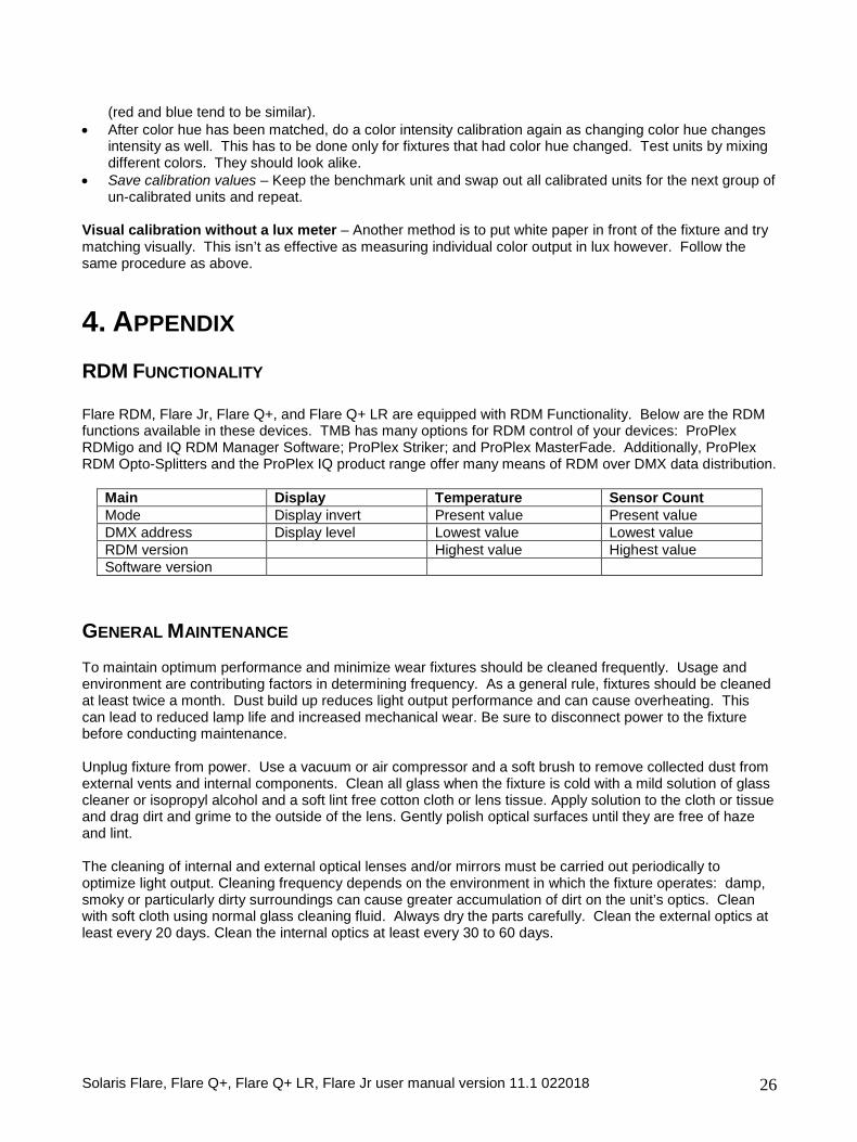
4. APPENDIX RDM FUNCTIONALITY Flare RDM, Flare Jr, Flare Q+, and Flare Q+ LR are equipped with RDM Functionality. Below are the RDM functions available in these devices. TMB has many options for RDM control of your devices: ProPlex RDMigo and IQ RDM Manager Software; ProPlex Striker; and ProPlex MasterFade. Additionally, ProPlex RDM Opto-Splitters and the ProPlex IQ product range offer many means of RDM over DMX data distribution.
Main Display Temperature Sensor Count Mode Display invert Present value Present value DMX address Display level Lowest value Lowest value RDM version Highest value Highest value Software version
GENERAL MAINTENANCE To maintain optimum performance and minimize wear fixtures should be cleaned frequently. Usage and environment are contributing factors in determining frequency. As a general rule, fixtures should be cleaned at least twice a month. Dust build up reduces light output performance and can cause overheating. This can lead to reduced lamp life and increased mechanical wear. Be sure to disconnect power to the fixture before conducting maintenance. Unplug fixture from power. Use a vacuum or air compressor and a soft brush to remove collected dust from external vents and internal components. Clean all glass when the fixture is cold with a mild solution of glass cleaner or isopropyl alcohol and a soft lint free cotton cloth or lens tissue. Apply solution to the cloth or tissue and drag dirt and grime to the outside of the lens. Gently polish optical surfaces until they are free of haze and lint. The cleaning of internal and external optical lenses and/or mirrors must be carried out periodically to optimize light output. Cleaning frequency depends on the environment in which the fixture operates: damp, smoky or particularly dirty surroundings can cause greater accumulation of dirt on the unit’s optics. Clean with soft cloth using normal glass cleaning fluid. Always dry the parts carefully. Clean the external optics at least every 20 days. Clean the internal optics at least every 30 to 60 days.
Solaris Flare, Flare Q+, Flare Q+ LR, Flare Jr user manual version 11.1 022018 27
LIMITED WARRANTY Solaris fixtures are warranted by TMB against defective materials or workmanship for a period of two (2) years from the date of original sale by TMB. TMB’s warranty shall be restricted to the repair or replacement of any part that proves to be defective and for which a claim is submitted to TMB before the expiration of the applicable warranty periods. This Limited Warranty is void if the defects of the Product are the result of: • Opening the casing, repair, or adjustment by anyone other than TMB or persons specifically authorized
by TMB • Accident, physical abuse, mishandling, or misapplication of the product. • Damage due to lightning, earthquake, flood, terrorism, war, or act of God. TMB will not assume responsibility for any labor expended, or materials used, to replace and/or repair the Product without TMB’s prior written authorization. Any repair of the Product in the field, and any associated labor charges, must be authorized in advance by TMB. Freight costs on warranty repairs are split 50/50: Customer pays to ship defective product to TMB; TMB pays to ship repaired product, ground freight, back to Customer. This warranty does not cover consequential damages or costs of any kind. A Return Merchandise Authorization (RMA) Number must be obtained from TMB prior to return of any defective merchandise for warranty or non-warranty repair. For all repairs please contact TMB Tech Support Repair using the contact information below or email [email protected]. US UK 527 Park Ave. 21 Armstrong Way San Fernando, CA 91340 Southall, UB2 4SD England Tel: +1 818.899.8818 Tel: +44 (0)20.8574.9700 Fax: +1 818.899.8813 Fax: +44 (0)20.8574.9701 [email protected] [email protected] www.tmb.com www.tmb.com
RETURN PROCEDURE Please send returned merchandise prepaid and in the original packing. Freight call tags will not be issued for shipping the product to TMB, but TMB will pay the freight for return to the customer. Clearly label package with a Return Merchandise Authorization Number (RMA #). Products returned without an RMA # will delay service. Please contact TMB and request an RMA # prior to shipping the unit. Be prepared to provide the model number, serial number, and a brief description of the cause for the return. Be sure to properly pack the unit; any shipping damage resulting from inadequate packaging is the customer’s responsibility. TMB reserves the right to use its own discretion to repair or replace product(s). Proper UPS packing or double-boxing will better ensure product integrity when shipped. Note: If you are given an RMA #, please include the following information on a piece of paper inside the box: 1) Your name 2) Your address 3) Your phone number 4) The RMA # 5) A brief description of the symptoms
Solaris Flare, Flare Q+, Flare Q+ LR, Flare Jr user manual version 11.1 022018 28
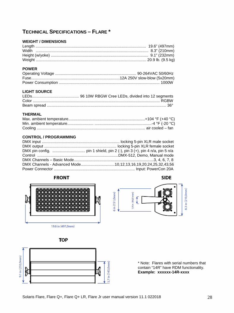
TECHNICAL SPECIFICATIONS – FLARE * WEIGHT / DIMENSIONS Length ..................................................................................................... 19.6” (497mm) Width ....................................................................................................... 8.3” (210mm) Height (w/yoke) ......................................................................................... 9.1” (232mm) Weight ..................................................................................................... 20.9 lb. (9.5 kg) POWER Operating Voltage .......................................................................... 90-264VAC 50/60Hz Fuse.................................................................................12A 250V slow-blow (5x20mm) Power Consumption ............................................................................................ 1000W LIGHT SOURCE LEDs........................................... 96 10W RBGW Cree LEDs, divided into 12 segments Color .................................................................................................................... RGBW Beam spread ............................................................................................................. 36° THERMAL Max. ambient temperature......................................................................+104 °F (+40 °C) Min. ambient temperature........................ ....................................................-4 °F (-20 °C) Cooling ................................................................................................... air cooled – fan CONTROL / PROGRAMMING DMX input ....................................................................... locking 5-pin XLR male socket DMX output .................................................................. locking 5-pin XLR female socket DMX pin config. .............................. pin 1 shield, pin 2 (-), pin 3 (+), pin 4 n/a, pin 5 n/a Control ..........................................................................DMX-512, Demo, Manual mode DMX Channels – Basic Mode.........................................................................3, 4, 6, 7, 8 DMX Channels - Advanced Mode...............................10,12,13,16,19,20,24,25,32,43,56 Power Connector .......................................................................... Input: PowerCon 20A
* Note: Flares with serial numbers that contain “14R” have RDM functionality. Example: xxxxxx-14R-xxxx
Solaris Flare, Flare Q+, Flare Q+ LR, Flare Jr user manual version 11.1 022018 29
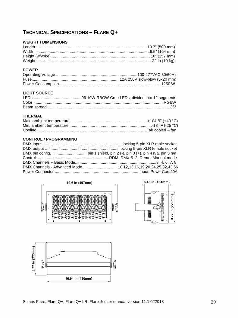
TECHNICAL SPECIFICATIONS – FLARE Q+ WEIGHT / DIMENSIONS Length ....................................................................................................19.7” (500 mm) Width ......................................................................................................6.5” (164 mm) Height (w/yoke) .........................................................................................10” (257 mm) Weight ........................................................................................................22 lb.(10 kg) POWER Operating Voltage .........................................................................100-277VAC 50/60Hz Fuse...............................................................................12A 250V slow-blow (5x20 mm) Power Consumption ...........................................................................................1250 W LIGHT SOURCE LEDs........................................... 96 10W RBGW Cree LEDs, divided into 12 segments Color .................................................................................................................... RGBW Beam spread ............................................................................................................. 36° THERMAL Max. ambient temperature......................................................................+104 °F (+40 °C) Min. ambient temperature........................ ..................................................-13 °F (-25 °C) Cooling ................................................................................................... air cooled – fan CONTROL / PROGRAMMING DMX input ....................................................................... locking 5-pin XLR male socket DMX output .................................................................. locking 5-pin XLR female socket DMX pin config. .............................. pin 1 shield, pin 2 (-), pin 3 (+), pin 4 n/a, pin 5 n/a Control ................................................................RDM, DMX-512, Demo, Manual mode DMX Channels – Basic Mode.........................................................................3, 4, 6, 7, 8 DMX Channels - Advanced Mode............................... 10,12,13,16,19,20,24,25,32,43,56 Power Connector ........................................................................... Input: PowerCon 20A
Solaris Flare, Flare Q+, Flare Q+ LR, Flare Jr user manual version 11.1 022018 30
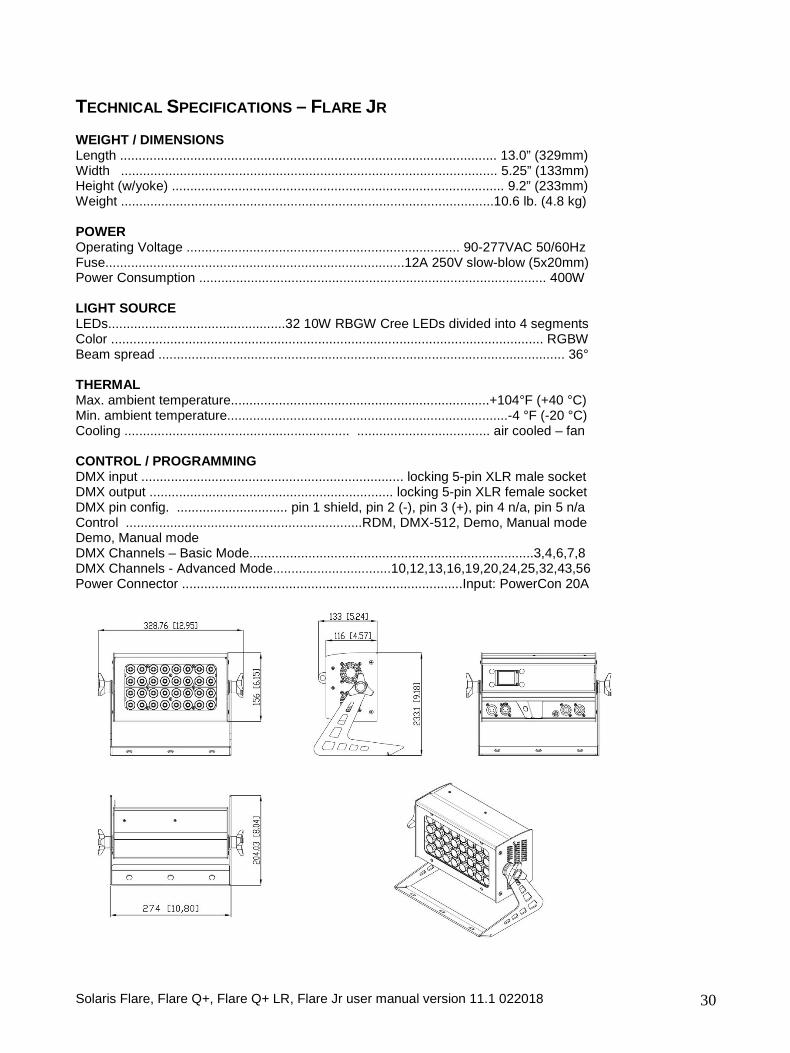
TECHNICAL SPECIFICATIONS – FLARE JR WEIGHT / DIMENSIONS Length ...................................................................................................... 13.0” (329mm) Width ...................................................................................................... 5.25” (133mm) Height (w/yoke) .......................................................................................... 9.2” (233mm) Weight .....................................................................................................10.6 lb. (4.8 kg) POWER Operating Voltage .......................................................................... 90-277VAC 50/60Hz Fuse.................................................................................12A 250V slow-blow (5x20mm) Power Consumption .............................................................................................. 400W LIGHT SOURCE LEDs................................................32 10W RBGW Cree LEDs divided into 4 segments Color ..................................................................................................................... RGBW Beam spread .............................................................................................................. 36° THERMAL Max. ambient temperature......................................................................+104°F (+40 °C) Min. ambient temperature............................................................................-4 °F (-20 °C) Cooling ............................................................. .................................... air cooled – fan CONTROL / PROGRAMMING DMX input ....................................................................... locking 5-pin XLR male socket DMX output .................................................................. locking 5-pin XLR female socket DMX pin config. .............................. pin 1 shield, pin 2 (-), pin 3 (+), pin 4 n/a, pin 5 n/a Control ................................................................RDM, DMX-512, Demo, Manual mode Demo, Manual mode DMX Channels – Basic Mode.............................................................................3,4,6,7,8 DMX Channels - Advanced Mode................................10,12,13,16,19,20,24,25,32,43,56 Power Connector ............................................................................Input: PowerCon 20A
Solaris Flare, Flare Q+, Flare Q+ LR, Flare Jr user manual version 11.1 022018 31
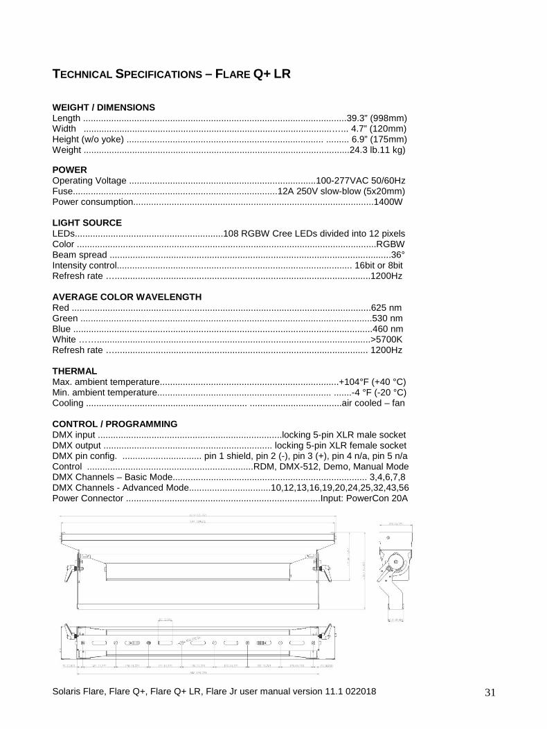
TECHNICAL SPECIFICATIONS – FLARE Q+ LR WEIGHT / DIMENSIONS Length .......................................................................................................39.3” (998mm) Width .................................................................................................…... 4.7” (120mm) Height (w/o yoke) ............................................................................. ......... 6.9” (175mm) Weight ........................................................................................................24.3 lb.11 kg) POWER Operating Voltage .........................................................................100-277VAC 50/60Hz Fuse................................................................................12A 250V slow-blow (5x20mm) Power consumption..............................................................................................1400W LIGHT SOURCE LEDs..........................................................108 RGBW Cree LEDs divided into 12 pixels Color .....................................................................................................................RGBW Beam spread ..............................................................................................................36° Intensity control............................................................................................ 16bit or 8bit Refresh rate …....................................................................................................1200Hz AVERAGE COLOR WAVELENGTH Red .....................................................................................................................625 nm Green ..................................................................................................................530 nm Blue .....................................................................................................................460 nm White ……...........................................................................................................>5700K Refresh rate …................................................................................................... 1200Hz THERMAL Max. ambient temperature......................................................................+104°F (+40 °C) Min. ambient temperature.................................................................... .......-4 °F (-20 °C) Cooling ............................................................... ....................................air cooled – fan CONTROL / PROGRAMMING DMX input ........................................................................locking 5-pin XLR male socket DMX output .................................................................. locking 5-pin XLR female socket DMX pin config. ............................... pin 1 shield, pin 2 (-), pin 3 (+), pin 4 n/a, pin 5 n/a Control .................................................................RDM, DMX-512, Demo, Manual Mode DMX Channels – Basic Mode............................................................................ 3,4,6,7,8 DMX Channels - Advanced Mode................................10,12,13,16,19,20,24,25,32,43,56 Power Connector ............................................................................Input: PowerCon 20A