Optimization example of industrial sewing machines mechanisms · Optimization example of industrial...
5
Optimization example of industrial sewing machines mechanisms Vlastimil Votrubec Pavel Šidlof VÚTS, a.s. U Jezu 4, 461 19 Liberec 4, Czech Republic [email protected], [email protected] Abstract This paper deals with the modeling and optimization of mechanical system, focusing on industrial sewing machines in order to reduce the vibrations by balanc- ing. It presents creation of model of mechanisms and their optimization using Modelica language through software MathModelica and Mathematica. Both ad- vantages and drawbacks of this approach are de- scribed and an example of optimization solution is shown. Keywords: optimization; mechanisms; sewing ma- chine 1 Introduction Our research institution partakes in development of industrial sewing machines focused on reduction of vibrations and noise. These properties significantly influence customer`s opinions and lead in this busi- ness helps with competition. It is necessary to solve similar problems for other types of machines also. Vibrations and noise are mainly caused by dy- namic forces generated during the movement of me- chanisms. To reduce these forces, which grow during the permanent rising of machines performance, dif- ferent balancing methods are used. The simplest me- thod is balancing by rotatory balancers. More signif- icant reduction of inertial forces is possible to achieve using balancing mechanisms. In our institute industrial used patent was developed in this field. It is necessary to use appropriate computational software for balance suggestion and optimization. One of the best and universal software is software Mathematica. Industrial sewing machines usually contain complicated system of mechanisms. Their dynamic calculation leads to a large number of equa- tions and parameters. We found that programming of the calculation is difficult and we could easily make mistakes, which were tedious to search. Hence the idea of using software MathModelica to create com- putational system occurred. Then we can execute optimization and some other calculations in software Mathematica. 2 Balancing of sewing machines Sewing machines contain number of mechanisms that cause generation of inertial forces and vibra- tions. Main of them is mechanism for needle bar mo- tion and thread feed mechanism. Both are placed in the head of the machine. There are crank mechanism that ensures reversible rectilinear movement of needle bar and four bar mechanism for thread feeder motion. Both mechanisms are driven by upper shaft that is connected to lower shaft by transmission belt. Balancing of these two mechanisms could be done by several methods. 2.1 Balancing methods Common balancing methods of inertial forces ba- lancing use rotatory balancers mounted on crank shaft. This method usually balances only centrifugal forces or transfers first harmonic component of iner- tial force of needle bar from the direction of needle bar axes to the orthogonal direction. Also this me- thod can´t balance higher orders harmonic compo- nent of inertial forces, especially in crank mechanism for needle bar motion. Further, the vibrations are often reduced by in- creasing of mass and thus increasing of stiffness of sewing machine`s head. Mounting in silent-blocks also helps. Using of balance mechanisms hasn´t spread yet, because most of these patented methods are compli- cated, expensive, require big space inside the ma- chine or they don’t balance inertial forces sufficient- ly. The VÚTS patent, which doesn´t have many of these drawbacks, was recently used to balance crank mechanism and partially thread feed mechanism. Proceedings 8th Modelica Conference, Dresden, Germany, March 20-22, 2011 791
-
Upload
dinhkhuong -
Category
Documents
-
view
221 -
download
1
Transcript of Optimization example of industrial sewing machines mechanisms · Optimization example of industrial...

Optimization example of industrial sewing machines mechanisms
Vlastimil Votrubec Pavel Šidlof VÚTS, a.s.
U Jezu 4, 461 19 Liberec 4, Czech Republic [email protected], [email protected]
Abstract
This paper deals with the modeling and optimization of mechanical system, focusing on industrial sewing machines in order to reduce the vibrations by balanc-ing. It presents creation of model of mechanisms and their optimization using Modelica language through software MathModelica and Mathematica. Both ad-vantages and drawbacks of this approach are de-scribed and an example of optimization solution is shown.
Keywords: optimization; mechanisms; sewing ma-chine
1 Introduction
Our research institution partakes in development of industrial sewing machines focused on reduction of vibrations and noise. These properties significantly influence customer`s opinions and lead in this busi-ness helps with competition. It is necessary to solve similar problems for other types of machines also.
Vibrations and noise are mainly caused by dy-namic forces generated during the movement of me-chanisms. To reduce these forces, which grow during the permanent rising of machines performance, dif-ferent balancing methods are used. The simplest me-thod is balancing by rotatory balancers. More signif-icant reduction of inertial forces is possible to achieve using balancing mechanisms. In our institute industrial used patent was developed in this field.
It is necessary to use appropriate computational software for balance suggestion and optimization. One of the best and universal software is software Mathematica. Industrial sewing machines usually contain complicated system of mechanisms. Their dynamic calculation leads to a large number of equa-tions and parameters. We found that programming of the calculation is difficult and we could easily make mistakes, which were tedious to search. Hence the idea of using software MathModelica to create com-putational system occurred. Then we can execute
optimization and some other calculations in software Mathematica.
2 Balancing of sewing machines
Sewing machines contain number of mechanisms that cause generation of inertial forces and vibra-tions. Main of them is mechanism for needle bar mo-tion and thread feed mechanism. Both are placed in the head of the machine. There are crank mechanism that ensures reversible rectilinear movement of needle bar and four bar mechanism for thread feeder motion. Both mechanisms are driven by upper shaft that is connected to lower shaft by transmission belt. Balancing of these two mechanisms could be done by several methods.
2.1 Balancing methods
Common balancing methods of inertial forces ba-lancing use rotatory balancers mounted on crank shaft. This method usually balances only centrifugal forces or transfers first harmonic component of iner-tial force of needle bar from the direction of needle bar axes to the orthogonal direction. Also this me-thod can´t balance higher orders harmonic compo-nent of inertial forces, especially in crank mechanism for needle bar motion.
Further, the vibrations are often reduced by in-creasing of mass and thus increasing of stiffness of sewing machine`s head. Mounting in silent-blocks also helps.
Using of balance mechanisms hasn´t spread yet, because most of these patented methods are compli-cated, expensive, require big space inside the ma-chine or they don’t balance inertial forces sufficient-ly. The VÚTS patent, which doesn´t have many of these drawbacks, was recently used to balance crank mechanism and partially thread feed mechanism.
Proceedings 8th Modelica Conference, Dresden, Germany, March 20-22, 2011
791
2.2 Calculation of mechanisms balancing and its limits
For optimization calculation it is necessary to use convenient software. In these cases software Mathe-matica was used. During the optimization it is neces-sary to solve system of equations which includes plenty of parameters. Program written in this way is large and it is easy to make mistakes that are difficult to be found.
Therefore we decided to work with software MathModelica that uses Modelica language and that is compatible with Mathematica. The idea was to create model of mechanisms in model editor using Modelica libraries, especially MultiBody library and then analyze it in Mathematica.
3 Optimization using Modelica lan-guage and Mathematica
Modeling of mechanisms has specific requests and many of them aren´t implemented in current libra-ries. Big advantage of this software is the ability to edit elements or even create new element and library.
3.1 Elements editing and creation
Most of the problems that we encounter when work-ing with mechanical systems first require detection of kinematic quantities courses at specific points in bodies and inertial forces (torques). However, ele-ments of the MultiBody library have these quantities defined differently and in smaller number than we need. Some kinematic quantities (velocity and acce-leration) are calculated resolved to individual body coordinate system, the total inertial force (torque) of the body isn´t defined at all and all variables are pri-marily calculated only for points of the body where the connection to other elements is modeled. It was necessary to remove these drawbacks so a new ele-ment of a rigid body (RigidBody) featuring a link of a mechanism was formed.
In the editor of the new element, new quantities and parameters were defined and relevant equations were set up. Kinematic quantities in points of con-nection to other elements, which we need to know resolved to global coordinate system, were simply multiplied with appropriate transformation matrix. It is also necessary to work with the courses of quanti-ties of an arbitrary point of the body (such as center of mass) which standard element doesn´t provide.
Therefore a radius vector of a general point re-solved to coordinate system of the body was set up as a new parameter. Other quantities are then calcu-
lated from this parameter. The position of this point resolved to global coordinate system is calculated as
LAGLGA rSrr ⋅+= ,
(1)
where rGL is position vector of the body coordinate system origin, S is transformation matrix, rLA is posi-tion vector of a point A resolved to the coordinate system of the body and rGA is searched position of a point A resolved to the global coordinate system.
The velocity and acceleration could be calculated as time derivatives of this formula, but function de-rivative can´t be used, because inserting of deriva-tives isn´t compatible with inner logic of the soft-ware and calculation is interrupted. For this reason velocity and acceleration of given point is calculated as
)( LAGAGLGA rrwvSv −×+⋅= , (2)
))((
)(
LAGA
LAGAGLGA
rrww
rrzaSa
−××+
+−×+⋅=
, (3)
where w and z are angular velocity and acceleration of the body, indexes GL correspond to the origin of the coordinate system of the body and indexes GA correspond to the searched global velocity and acce-leration of the given point.
Inertial force F is defined by multiple of body mass m and its acceleration in the center of mass aGT. The acceleration is calculated according to relations (1, 2, 3), only instead of position vector rLA, the posi-tion vector of center of mass rLT is inserted
GTamF ⋅= . (4)
In the similar way inertial torque is calculated, only instead of body mass, moment of inertia re-solved to the center of mass and angular acceleration of the body are inserted. This method allows us to
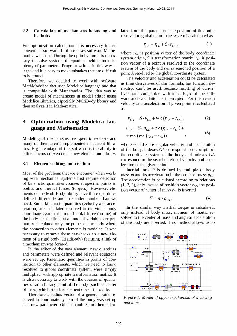
Figure 1: Model of upper mechanism of a sewing machine.
Proceedings 8th Modelica Conference, Dresden, Germany, March 20-22, 2011
792

enlarge elements with new parameters and quantities according as necessary.
There can be relatively a lot of mechanisms in-side the sewing machine (according to the type of machine). These mechanisms can form a long chain. Already the model of simple mechanism such as crank mechanism or four bar mechanism from fig. 1 includes about ten elements. For easier work and better orientation it is convenient to assemble these simple mechanisms into blocks and form indepen-dent elements from them, which are then connected.
The upper mechanism model of a sewing ma-chine from fig. 1 is then simplified to model that has only five elements (fig. 2). Used elements represent global coordinate system, planar crank mechanism and binary revolute pair replacing four bar mechan-ism of thread feeder, all for suggested constant value of crank shaft angular velocity which is connected to the CrankMech2D element.
3.2 Optimization
Optimization of chosen parameters of the model is then solved in Mathematica. There is created func-tion for finding local minimum that searches the mi-nimal value for every parameters setting. During every step of finding minimum is solved whole sys-tem of equations in MathModelica Simulation Cen-ter. There is also possible to use any of other opera-tors that the software offers, such as finding local maximum, difference between two courses, finding of roots of derivatives etc.
Generally the optimization is difficult calculation. During the balancing of mechanisms and machines (reduction of total dynamic forces and torques) it is possible to use specific properties of this problem. Usually mechanisms with periodic movement are
solved and balanced so that optimal dimensions and moments of inertia of several balancing masses are found. Each body is possible to replace by proper chosen point masses if the flexibility is omitted (3 points are enough for plane case). Total inertial force is then sum of inertial forces in these points.
For example it is searching minimum of absolute value of F in vector function
nn amamamF ⋅++⋅+⋅= ...2211 . (5)
If points are chosen conveniently, then only the mass mi of points is necessary to find, not their optimum position. Courses of acceleration ai, which are gener-ally given by very complicated relations, are there-fore in particular points stable, they can be calculated before the optimization and don´t have to be ex-ecuted in each optimization step. In order to effective calculation using MathModelica, it is necessary to do some modifications and completion in this software.
3.3 Drawbacks of this approach
There are several difficulties which make optimiza-tion complicated. Firstly it is absence of some me-chanical elements and joints in MultiBody library. For instance a lot of mechanisms in sewing and other machines consist of cams and other shape bodies which can´t be modeled by means of standard ele-ments. Hence, joint between cam and lift and other elements would help much in mechanisms modeling.
Next problem is time of optimization. Elements of mechanism model form system of equations which includes thousands equations. Already simple mechanism such as four bar mechanism has about 3000 equations, 2500 of them are trivial equations. Although the simulation takes a few seconds, it is executed in every step during the optimization. Find-ing local minimum is a long process with dozens up to hundreds of steps. This finally causes long time of a calculation depends on model difficulty and num-ber of parameters. Each other used parameter for optimization significantly lengthens the time of cal-culation.
3.4 Possible approaches of next process
One possible solution of the problem with time of optimization was found in solving of whole system of equations independently on Simulation Center which could be much more efficient. MathModelica allows transferring the system of equations to soft-ware Mathematica. Mathematica offers many opera-tors for solving equations, the most appropriate oper-ator for this case is function NDSolve that can nu-merically solve system of differential equations.
Figure 2: Model of upper mechanisms of sewing machine. Both mechanisms are replaced with single element.
Proceedings 8th Modelica Conference, Dresden, Germany, March 20-22, 2011
793

This approach also has some problems which don´t enable to sufficiently solve equations for this time.
3.5 Optimization example
It will be presented optimization example of balanc-ing on upper mechanisms of sewing machine in this item. As was said before, there are two mechanisms driven by upper shaft, crank mechanism and four bar mechanism. Total inertial force is a sum of particular forces of the bodies. The biggest influences on total inertial force have inertial forces generated by movement of crank shaft and needle bar. The courses of unbalanced total inertial force and its components are on the fig. 3, whereas the crank shaft is rotating 3000 RPM counter clockwise.
The polar diagram shows resulting force vector. The arrows present vectors for particular drive shaft angle rotation in degrees.
Generally the reduction of total inertial force can be achieved by using two rotatory balancers on the crank shaft. But in this case the crank shaft is pre-balanced. Position of center of mass is near the axis of rotation so balancing using rotatory balancers can´t help much. Significant reduction of the total force is possible to achieve using a balancing me-chanism and one rotatory balancer. In our case it consists from connecting rod that is mounted on the crank shaft on the opposite side of the needle bar crank and balancer (fig. 4). The balancer has small stroke but large mass. Also there is one rotatory ba-lancer placed on the crank shaft.
The dimensions of balancer and balancing me-chanism are fixed, so there are two values to optim-ize, mass of the rotatory balancer and mass of ba-lancer of balancing mechanism. Then in Mathemati-ca is constructed function for calculation of total in-ertial force, finding the maximum value of that force and the parameters are set. Optimization then implies that the operator for finding local minimum is chang-ing parameters (mass of balancers) until it finds the minimum value.
Calculation lasts about 60 minutes (3 GHz pro-cessor, 1.99 GB RAM), for one parameter it lasts 30 minutes. It is clear that for more complicated model
Figure 3: Polar plot of total inertial force of unba-lanced upper mechanism. The maximum force is 100,9N.
Figure 5: Polar plot of total inertial force of upper mechanisms after the optimization. The maximum force is 38,7N.
Figure 4: Schema of upper mechanisms of sewing machine. Needle bar mechanism and thread feed-er mechanism with additional balancing mechan-ism.
Proceedings 8th Modelica Conference, Dresden, Germany, March 20-22, 2011
794
and more parameters the optimization would take hours. The results are shown on figure 5. The reduc-tion of total inertial force is relatively significant, maximum of total force descended about 60%.
4 Conclusion
Mentioned approach allows modeling of system of mechanisms, executing kinematic and dynamic anal-ysis and optimizing parameters to reduce inertial forces and vibrations. This approach is clear and it reduced mistakes in comparison with other software and methods. On the optimization example of ba-lancers is shown how it is possible to achieve fast and precise results.
On the other hand there is still large area for im-proving current methods and means in optimizations. For example mechanical elements that corresponds to real links of mechanisms and design problems, possibility to enter more mass parameters etc.
Proceedings 8th Modelica Conference, Dresden, Germany, March 20-22, 2011
795


![MySewingMall.com [Sewing Machine Parts & Sewing Jargons]](https://static.fdocuments.in/doc/165x107/587a415b1a28ab00148b4837/mysewingmallcom-sewing-machine-parts-sewing-jargons.jpg)