Optimal Connection of Heat Pump and Solar Buffer Storage ... · Within a comprehensive...
10
1876-6102 © 2016 Published by Elsevier Ltd. This is an open access article under the CC BY-NC-ND license (http://creativecommons.org/licenses/by-nc-nd/4.0/). Peer-review by the scientific conference committee of SHC 2015 under responsibility of PSE AG doi:10.1016/j.egypro.2016.06.190 Energy Procedia 91 (2016) 145 – 154 ScienceDirect SHC 2015, International Conference on Solar Heating and Cooling for Buildings and Industry Optimal connection of heat pump and solar buffer storage under different boundary conditions Jens Glembin*, Christoph Büttner, Jan Steinweg and Gunter Rockendorf Institut für Solarenergieforschung Hameln/Emmerthal (ISFH), Am Ohrberg 1, 31860 Emmerthal, Germany Abstract The paper presents the results of a simulation study, in which the connection of heat pumps and buffer storage tanks has been investigated. The simulations are carried out for a new type of a solar thermal combi system with a 32 m² collector field leading to a solar fraction of more than 50 %. In the first stage, the most influencing installation and operation parameters have been identified and optimized for typical boundary conditions of weather/climate, hot water demand, building and space heating system. Within further simulations these boundary conditions are varied to find generalized design rules for the connection of heat pumps and storage tanks. These results are presented and discussed. Keywords: Heat pump; buffer storage; boundary conditions; solar active house; system simulation; solar fraction 1. Introduction Heat pumps have a significant and increasing share in the European heating market, e.g. in Germany 9 % of the heat generators in buildings installed in 2014 have been heat pumps [1]. In most applications, especially in space heating systems equipped with thermostatic valves, heat pumps are operated with a storage tank. The design of the storage and its connection to the heat pump has a significant influence on the performance of the heat pump and the whole system, see e.g. [2]. * Corresponding author. Tel.: +49-5151-999-647; fax: +49-5151-999-600. E-mail address: [email protected] Available online at www.sciencedirect.com © 2016 Published by Elsevier Ltd. This is an open access article under the CC BY-NC-ND license (http://creativecommons.org/licenses/by-nc-nd/4.0/). Peer-review by the scientific conference committee of SHC 2015 under responsibility of PSE AG
Transcript of Optimal Connection of Heat Pump and Solar Buffer Storage ... · Within a comprehensive...

1876-6102 © 2016 Published by Elsevier Ltd. This is an open access article under the CC BY-NC-ND license (http://creativecommons.org/licenses/by-nc-nd/4.0/).Peer-review by the scientific conference committee of SHC 2015 under responsibility of PSE AGdoi: 10.1016/j.egypro.2016.06.190
Energy Procedia 91 ( 2016 ) 145 – 154
ScienceDirect
SHC 2015, International Conference on Solar Heating and Cooling for Buildings and Industry
Optimal connection of heat pump and solar buffer storage under different boundary conditions
Jens Glembin*, Christoph Büttner, Jan Steinweg and Gunter Rockendorf Institut für Solarenergieforschung Hameln/Emmerthal (ISFH), Am Ohrberg 1, 31860 Emmerthal, Germany
Abstract
The paper presents the results of a simulation study, in which the connection of heat pumps and buffer storage tanks has been investigated. The simulations are carried out for a new type of a solar thermal combi system with a 32 m² collector field leading to a solar fraction of more than 50 %. In the first stage, the most influencing installation and operation parameters have been identified and optimized for typical boundary conditions of weather/climate, hot water demand, building and space heating system. Within further simulations these boundary conditions are varied to find generalized design rules for the connection of heat pumps and storage tanks. These results are presented and discussed. © 2015 The Authors. Published by Elsevier Ltd. Peer-review by the scientific conference committee of SHC 2015 under responsibility of PSE AG.
Keywords: Heat pump; buffer storage; boundary conditions; solar active house; system simulation; solar fraction
1. Introduction
Heat pumps have a significant and increasing share in the European heating market, e.g. in Germany 9 % of the heat generators in buildings installed in 2014 have been heat pumps [1]. In most applications, especially in space heating systems equipped with thermostatic valves, heat pumps are operated with a storage tank. The design of the storage and its connection to the heat pump has a significant influence on the performance of the heat pump and the whole system, see e.g. [2].
* Corresponding author. Tel.: +49-5151-999-647; fax: +49-5151-999-600.
E-mail address: [email protected]
Available online at www.sciencedirect.com
© 2016 Published by Elsevier Ltd. This is an open access article under the CC BY-NC-ND license (http://creativecommons.org/licenses/by-nc-nd/4.0/).Peer-review by the scientific conference committee of SHC 2015 under responsibility of PSE AG

146 Jens Glembin et al. / Energy Procedia 91 ( 2016 ) 145 – 154
Within a comprehensive investigation, system simulations in TRNSYS are used to identify the optimum design of the connection between a heat pump and a solar buffer storage including total storage volume, number and size of heated zones, sensor and in- and outlet positions. These parameters are investigated within a new developed heat supply concept for solar active houses with a solar thermal fraction of more than 50 %. The solar heat is either used in thermally activated concrete elements or within a buffer storage which distributes its heat to the space heating circuit and the domestic hot water preparation. In addition, a heat pump charges the buffer storage in order to cover the remaining heat demand. Within the present investigation the system serves as a back-ground for the analysis of the connection of heat pump and storage tank. Fig. 1 (left) shows a layout scheme of the concept while a detailed system description and an analysis with a focus on the solar thermal performance is published in [3].
It has to be noted that the investigation covers non-modulating heat pumps, that means the heat pump only operates in on-/off mode and is not able to heat the fluid to a set temperature. Especially in the case of air as heat source, several heat pumps on the market are modulating. This changes the operation characteristics of the heat pump drastically and also affects the connection to a buffer storage. Therefore, the investigation results presented here are only valid for non-modulating heat pumps. Nonetheless, non-modulating ground source heat pumps have a significant market at the moment with efficiencies usually higher than air-source heat pumps.
Fig. 1. Left: Scheme of the solar thermal heating system for the investigation (the lines indicate energy flows), right: Scheme of buffer storage with two heated zones and its connections to heat pump, solar thermal collectors and heat sinks
Nomenclature
BHE Borehole heat exchanger DHW Domestic hot water HP Heat pump Rad Radiator SH Space heating SPF Seasonal performance factor

Jens Glembin et al. / Energy Procedia 91 ( 2016 ) 145 – 154 147
2. Methodology and former results
The system presented in Fig. 1 is simulated in TRNSYS 17 [4] under the boundary conditions shown in Table 1.
Table 1: Boundary conditions for the simulations in TRNSYS
Data TRNSYS Type/Model
Location Zurich, Switzerland Weather data from
Meteonorm [5] Building
Heated area 270 m² Type 56 [4]
Heat demand 11800 kWh/a (constant infiltration rate
0.4 h-1/20 °C room temperature) Space heating
Type Radiators Type 362[6] Design temperatures
(Flow/return) 55 °C / 45 °C at -14 °C ambient temperature 35 °C / 30 °C at 20 °C ambient temperature
Domestic hot water demand
2200 kWh/a Based on IEA Task 44[7]
Collector 32 m² selective flat plate collector/tilted 45°, south Type 832 [8] Storage tank Dimensions Volume 1 m³, height 2 m, diameter 0.8 m
Type 340[9] Heat loss rate
Insulation 0.1 m with 0.037 W/mK, overall heat loss 4.1 W/k
Heat pump Working point B0/W35
(DIN EN 255) Heating power 8.1 kW (condenser output), COP 4.8
Type 401[10] and Type 292 for flow rate adaption
[11]
Volume flow rates Evaporator 1.9 m³/h, condenser 0.7 m³/h
Dynamics Heat up constant 30 s, cool down constant 5 min,
minimum turn-off time 10 min Heating rod Power 7 kW Heat source Borehole with 70 m depth Type 557[12]
The heat pump parameters are identified for a typical device used in single family houses which had been measured on a test rig at ISFH. The heat pump controller determines the operation signals for the heat pump itself and the heating rod. The latter is used, if the current operating conditions do not allow the standard heat pump mode, e.g. if the heat source temperature is below a certain limit (here -5 °C).
Fig. 1 on the right shows a scheme of the buffer storage charged by the heat pump and 32 m² of solar thermal collectors. The heat pump (HP) charges two zones in the storage, the upper zone supplies the fresh water station (FWS) for preparation of domestic hot water (DHW) while the lower zone is used for space heating (SH). Alternatively, the heat pump may also charge only one zone for both applications. The following sections of the storage tank can be defined.
The dead volume is situated above the upper heated zone between outlet to the FWS and inlet of the heat pump. The DHW volume is charged directly by the heat pump to a constant set temperature. Charging the DHW zone
has a higher priority than the SH zone. The separation volume separates both heated zones.

148 Jens Glembin et al. / Energy Procedia 91 ( 2016 ) 145 – 154
The SH volume is used for space heating and is charged with second priority. The set temperature may be constant or variable following the desired flow temperature according to heating curve and the current ambient temperature.
The solar volume is only charged by the solar thermal collectors.
A simulation study is used to determine the system performance under variation of several parameters characterizing the heat pump storage connection. In the first stage of the investigation published in [13], the most important parameters concerning the heat pump storage connection and their optimum values are identified. Summarizing, Fig. 2 shows the overall annual systems’ energy demand and the seasonal performance factor SPF of the heat pump before and after optimizing the most significant parameters. The SPF is the ratio of the heat pump condenser output to the electricity consumption in the period of one year considering the electricity consumption of the heat pump itself and the heating rod.
Fig. 2. Overall electricity consumption and seasonal performance factor of the heat pump for the base settings of the heat pump storage connection and after optimization of several parameters
The first part of the study reveals some important facts regarding the connection of heat pump and storage tank.
A sharp decrease in the energy demand can be reached if the storage is equipped with two separated heated zones for space heating and domestic hot water instead of only one zone for both applications.
The set temperature of the DHW zone has only a small impact on the system performance, while the set temperature in the SH zone should be variable according to the heating curve.
The sensor position defines the volume which is kept on the set temperature. A high sensor position reduces this volume and thus the electricity consumption as well as the heat pump cycles. However, a lower sensor position allows a lower set temperature without reducing the comfort.
The heat pump flow rates should be minimized with regard to the characteristics of the ground heat exchanger in case of the evaporator and to the rise of the inlet temperature in case of the condenser side.
The optimum variants have a DHW volume of 100 l and a SH volume between 200 and 300 l. Either a volume between both heated zones (separation zone) and a volume above the upper heated zone (dead zone) are necessary but may be reduced to a small volume of e.g. 40 l each.
Overall: The total electricity consumption may be reduced by almost 15 % with an optimum heat pump storage connection compared to the base case with one heated zone and by 6 % compared to the base case with two heated zones.

Jens Glembin et al. / Energy Procedia 91 ( 2016 ) 145 – 154 149
Within the first stage, the boundary conditions of the system simulations had been constant. But these conditions may affect the optimum connection of heat pump and buffer storage. Therefore, the following boundary conditions are varied within the second stage:
Minimum standby time of the heat pump (Base setting: 10 min): 0 min, 20 min Length of borehole heat exchanger BHE (70 m): 80 m Room set temperature (20 °C): 19 °C, 21 °C Temperature difference between space heating in-/outlet (10 K): 5 K, 15 K Weather (Zurich/Meteonorm): Measured data for Hanover of 1996 and 2000 Domestic hot water demand (2170 kWh/a with tapping profile according to IEA Task 44): 3000 kWh/a with
profile according to IEA Task 32 [14]. Building (270 m² with 44 kWh/m²a): 180 m² with 42 kWh/m²a Heating curve (55 °C/45 °C): 65 °C/55 °C, 45 °C/35 °C. The change in the heating curve requires a new
dimensioning of the radiators. Heating elements (radiators with 55 °C/45 °C): floor heating with 35 °C/30 °C
3. Results
Fig. 3 gives an overview of the system performance for the different boundary conditions. The heat pump connection is set to the base case according to Fig. 2 with two heated zones.
Fig. 3. Electricity consumption of heat pump, heating rod and the overall system as well as the seasonal performance factor of the heat pump (same definition as in Fig. 3) for the base case system with two heated zones by varying the boundary conditions
The diagram identifies boundary conditions with a strong or a small impact on the system performance. Most significantly, the weather data leads to an increase of 46 % or decrease of 31 % in the electricity consumption. Compared to that, the decrease in electricity consumption is small, if the radiators are replaced by a floor heating system. The low operating temperatures of the floor heating lead to a reduced electricity consumption of the compressor and increases the heat extraction from the ground. Due to the higher heat extraction, the ground source temperature reaches earlier the minimum evaporator temperature of -5 °C compared to the radiator system. The consequence is a higher operation time of the heating rod which increases the electricity consumption considerably.

150 Jens Glembin et al. / Energy Procedia 91 ( 2016 ) 145 – 154
This negative effect can be reduced significantly or even avoided if using a larger heat pump source that is a longer borehole.
The results indicate that the electricity consumption and the annual heat pump performance are influenced significantly by the boundary conditions. The following sections analyze how the boundary conditions affect the optimum settings for the heat pump storage connection. Therefore, system simulations are carried out with the most important parameter sets characterizing the heat pump storage connection for all the boundary conditions shown in Fig. 3. Section 3.1 shows exemplarily the variations of set temperature and volume of the SH zone for different weather data. These simulations allow the definition of the optimum values leading to the lowest energy consumption. Section 3.2 presents the optimum settings of these parameters for all boundary conditions.
3.1. Optimization at varying weather conditions
Exemplarily for the investigation, this section shows the parameter variations characterizing the lower auxiliary zone for space heating at different climatic conditions. Apart from the Meteonorm data for Zurich, the simulations are carried out with two years out of the data measured of ISFH for Hanover during the period 1989 to 2001. The year 1996 has the coldest temperatures within the heating period leading to the highest annually space heat demand while the year 2000 represents one of the warmest years with a low space heat demand.
Fig. 4 presents the overall electricity consumption of all variations concerning the SH zone. The results with different volumes are shown on the left side, in which the variant 0 l represents the case of only one heated zone. The right diagram shows the variations of the set temperature in the SH zone.
Fig. 4. Overall electricity demand in the simulations with three weather data sets. The variants “Base” marks the adjustments in the base case with two heated zones. Left: Variation of the SH volume. The volume of 0 l represents the result in the case of one heated zone. Right: Variations in the set temperature. The temperature in the lower x-Axis corresponds to the constant temperature while the upper x-Axis corresponds to the shifting in the variable temperature (base case: 0 K). Variants leading to room temperatures below the comfort limit are not displayed.
As already shown in Fig. 2 the weather data of 1996 leads to a higher electricity consumption while it decreases for 2000. The effect of the second auxiliary zone are more pronounced in 2000 (-15 %) compared to the other weather data (both -7 %). Since the SH zone in the base case is heated according to the heating curve, the higher outside temperatures in 2000 lead to lower set temperatures in the SH zone. This increases the temperature difference to the upper zone. Therefore, an additional second zone has a higher effect on the condenser temperature and thus the heat pump performance. The weather data also affects the optimum volume (180 l for 1996 up to 500 l for 2000) and the maximum possible improvement, which is between 1.6 % and 5.1 %.
Jens Glembin et al. / Energy Procedia 91 ( 2016 ) 145 – 154 151
There is a large difference between a constant and a variable set temperature. The disadvantage of a constant set temperature becomes obvious in the right diagram. For reaching the comfort in the building (20 °C room temperature) the set temperature has to be increased from 41 °C in 2000 to 48 °C in 1996. The variable temperature is set to the heating curve flow temperature which considers the ambient temperature conditions in the different weather data. Therefore, the possible reduction in the variable temperature is the same for all data sets. The variable set temperature may set 7 K below the heating curve independent of the weather data. This temperature reduction is more advantageous at a lower heating load as for 2000 and Zurich (decrease by 4 %) compared to 1996 (-2.5 %).
3.2. General results for SH zone
The simulations concerning the lower auxiliary zone analysis in Section 3.1 are carried out for all boundary conditions described in Section 2. This section sums up the outcomes of all variants.
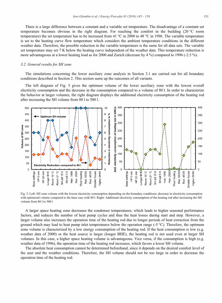
The left diagram of Fig. 5 gives the optimum volume of the lower auxiliary zone with the lowest overall electricity consumption and the decrease in the consumption compared to a volume of 80 l. In order to characterize the behavior at larger volumes, the right diagram displays the additional electricity consumption of the heating rod after increasing the SH volume from 80 l to 500 l.
Fig. 5. Left: SH zone volume with the lowest electricity consumption depending on the boundary conditions; decrease in electricity consumption with optimized volume compared to the base case with 80 l. Right: Additional electricity consumption of the heating rod after increasing the SH volume from 80 l to 500 l
A larger space heating zone decreases the condenser temperatures, which leads to higher seasonal performance factors, and reduces the number of heat pump cycles and thus the heat losses during start and stop. However, a larger volume also increases the operation time of the heating rod due to longer periods of heat extraction from the ground which may lead to heat pump inlet temperatures below the operation range (-5 °C). Therefore, the optimum zone volume is characterized by a low energy consumption of the heating rod. If the heat consumption is low (e.g. weather data of 2000) or the heat source is larger (longer BHE), the heating rod is not used even at larger SH volumes. In this case, a higher space heating volume is advantageous. Vice versa, if the consumption is high (e.g. weather data of 1996), the operation time of the heating rod increases, which favors a lower SH volume.
The absolute heat consumption cannot be determined beforehand, since it depends on the desired comfort level of the user and the weather conditions. Therefore, the SH volume should not be too large in order to decrease the operation time of the heating rod.

152 Jens Glembin et al. / Energy Procedia 91 ( 2016 ) 145 – 154
Fig. 6 shows the optimum set temperature in the SH zone for different boundary conditions. The left diagram gives the optimum constant set temperature and the change of this variant compared to the base case with a variable set temperature according to the heating curve. The right diagram shows the maximum possible reduction in the variable set temperature without affecting the comfort. For these variants the diagram gives the reduction in the electricity consumption compared to the base case.
Fig. 6. Optimal set temperatures in the SH zone for different boundary conditions. Left: Constant set temperature and reduction in electricity consumption compared to the base case (negative values corresponds to higher consumption), Right: Possible change in the variable set temperature without affecting the comfort. Variants with floor heating include a different heating curve; variants with other heating curves (Rad. 65/55, Rad. 45/35) include a new dimensioning of the radiators
The left diagram shows, that a constant set temperature for the SH zone is not useful at changing boundary conditions. The optimal set value depends not only on system-specific settings (e.g. heat pump type, space heating system), but also on other factors as the weather conditions. The optimum value differ from 31 °C to 49 °C while the change in electricity consumption compared to the variable temperature setting can be more than 10 %, but may be also below 0 which corresponds to a higher consumption.
The right diagram reveals electricity savings of up to 13 % if the lowest possible variable set temperature is used. The possible reduction compared to the heating curve depends on dimensioning and type of the space heating element and the actual demand. The temperature in the storage may be reduced significantly (Rad. 65/55, Room 19 °C) or the reduction is small (Room 21 °C) or not possible (Rad. 45/35, higher DHW demand). Other factors, e.g. the weather, are not influencing the optimum set temperature (all -7 K). An exception is the behavior at longer standby periods of the heat pump (maximum -3 K possible). A longer minimum standby period avoids a fast heat pump reaction after switching off. In the case of a high space heat demand, a higher set temperature ensures that the heat delivered to the heating elements is sufficient until the heat pump is able to be switched on again.
The reduced set temperature leads to lower temperatures in the space heating circuit as demanded by the heating curve. This indicates an over-dimensioning of the space heating components. Within the simulations, the dimensioning of the radiators was done according to the usual standardized method considering a radiator exponent of 1.3. However, the simulated building has only one heated zone per story each equipped with one large radiator and long non-insulated connecting pipes. These pipes increase the surface for heat emission in the space heating circuit especially at high flow/return temperatures. This explains the high possible reduction in the variant Rad. 65/55 (-10 K) and no reduction in Rad. 45/35 and only -1 K in the case of floor heating with 2 m of connecting pipes.

Jens Glembin et al. / Energy Procedia 91 ( 2016 ) 145 – 154 153
In conclusion, an optimum set temperature in the lower auxiliary volume requires a well dimensionized space heating system. In this case, the lowest energy consumption is reached, if the current flow temperature of space heating system is used as the set temperature. However, a slow response from the auxiliary heater may necessitate higher set temperatures.
4. Conclusions
Based on the outcomes of all simulations, some general recommendations may be defined how to connect a heat pump with a storage tank in a solar thermal combi system:
In general, a second heated zone in the storage tank is advantageous, the performance improvement increases with the temperature difference between hot water preparation and space heating. If the temperature level within the space heating circuit is in the range of the DHW temperature (e.g. radiators with high system temperatures), a second zone has no advantage and may even lead to a higher energy consumption.
An additional zone above the upper heat pump inlet leads to a small increase in the energy consumption while it increases the comfort of the DHW preparation during heat pump operation. Another zone between space heating and DHW volume reduces the mixing of both auxiliary zones especially at high temperature differences. The purpose of both zones may be reached with a small volume.
The volume of the upper auxiliary zone is less important while the optimum volume of the lower zone depends on the boundary conditions. A larger space heating volume leads to lower condenser temperatures but also increases the operation time of the heating rod. The latter increases especially at a high system load, e.g. a hard winter. Therefore, the volume mustn’t be too large (here 300 l is the optimum) although the electricity consumption is higher than the optimum during years with a small heating load.
The lower auxiliary zone servers as a pre-heater for the upper zone leading to higher condenser temperatures if charging the upper zone. This results in a frequent exceeding of the set temperature. Therefore, this value may be set to the desired domestic hot water temperature after the fresh water station. Alternatively, the frequency of high condenser temperature may be limited by a high position of the temperature sensor.
The lower auxiliary zone may be heated with a constant set temperature. However, a variable temperature depending on the outside temperature according to the heating curve is more advantageous. In the case of a slow respondent auxiliary heater (e.g. heat pump with a long standby period), a higher set temperature may avoid a decrease of the room temperature below the comfort limit. This measure shows a higher effect than a larger SH volume which also shows the above mentioned disadvantages.
The evaporator flow rate of the heat pump influences mainly the electricity consumption of the circulation pump, which outweighs all other effects on the heat pump efficiency. Therefore, a low evaporator flow rate is advantageous.
The condenser flow rate affects the temperature difference between in- and outlet. With a large temperature difference, the risk of exceeding the set temperature increases. On the other hand, with the same set temperature a small temperature difference leads to a lower average condenser temperature. One of these effects outweighs the other, depending on the temperature level at the heat pump inlet. While a higher flow rate is advantageous in the upper zone with its high temperature level, the performance increases with a low flow rate in the SH zone. However, the heat pump flow rate should be above the design flow rate of the space heating system. Otherwise, the flow rate from the heat pump is directly used in the space heating circuit without an effect on the auxiliary zone and its control sensor leading to condenser outlet temperatures above the set value which decrease the heat pump performance.
Since all the recommendations base solely on simulation results, an extension of the investigation, e.g. by measurements on a test rig, may be reasonable. Likewise, the interaction of the parameters is not analyzed. This concerns the simultaneous variation of two parameters (e.g. sensor position and condenser flow rate) or two boundary conditions (e.g. floor heating and other weather conditions). As mentioned in the Section 1, the outcomes are valid for the combination of buffer storage and one stage heat pumps, which are only operated in on or off. Design rules for modulating heat pumps, which are able to control their outlet temperature, require further simulations.

154 Jens Glembin et al. / Energy Procedia 91 ( 2016 ) 145 – 154
Acknowledgements
The investigations were realized within the project “SH-T-opt”, FKZ 0325981, which was carried out in cooperation with the companies HELMA Eigenheimbau AG and RESOL – Elektronische Regelungen GmbH and funded by the German Federal Ministry for Economic Affairs and Energy on the basis of a decision of the German Federal Parliament. The authors are grateful for the financial support. The content of this publication is in the responsibility of the authors.
References
[1] Bundesindustrieverband Deutschland Haus-, Energie- und Umwelttechnik e.V. (BDH), Bilanz Heizungsindustrie 2014. [2] Haller, M, et al. Hydraulic integration and control of heat pump and combi-storage: Same components, big differences, Energy Procedia 48,
pp. 571-580, 2014 [3] Glembin, J., et al. Solar active building with directly heated concrete floor slabs, Energy Procedia 48, pp. 561-570, 2014 [4] Klein SA, et al. TRNSYS 17, A Transient System Simulation Program, Solar Energy Laboratory University of Wisconsin, Madison, 2009. [5] Remund J., Kunz S. Meteonorm Data (Worldwide), METEOTEST, Bern, Switzerland, 2003 [6] Holst S. Type 362 Dynamic radiator model with pipes (Type 162), Bayerisches Zentrum für angewandte Energieforschung e.V., München,
Germany, 2010. [7] Dott R., et al. Models of Sub-Components and Validation for the IEA SHC Task 44 / HPP Annex 38 Part C: Heat Pump Models, A technical
report of subtask C Deliverable C2.1 Part C, International Energy Agency, 2012. [8] Haller M. and Perers B. Type 832, Dynamic Collector Model, Institut für Solartechnik, Hochschule für Technik Rapperswil, Zurich,
Switzerland, 2012. [9] Drück H. Type 340, MULTIPORT Store - Model for TRNSYS, Institut für Thermodynamik und Wärmetechnik (ITW) Universität Stuttgart,
Stuttgart, Germany, 2006. [10] Afjei T and Wetter M. Type 401,Compressor heat pump including frost and cycle losses, Zentralschweizerisches Technikum Luzern,
Ingenieurschule HTL, Zurich/Luzern, Switzerland, 1997. [11] Institut für Solarenergieforschung Hameln ISFH. TRNSYS Type 292: Component for heat pump to correct for different flow conditions in
condenser or evaporator, 2013 [12] TESS COMPONENT LIBRARIES General Descriptions, Tess Thermal Energy System Specialists, Madison, Wisconsin, USA, 2011 [13] Glembin, et al. Thermal storage tanks in high efficiency heat pump systems – optimized installation and operation parameters, Energy
Procedia 73, pp. 331-340, 2015 [14] Heimrath, R. and Haller, M. The reference heating system, the templated solar system of Task 32, Report A2 of Substask A, IEA SHC
Task 32, 2007