TRNSYS EXTENSIONS FOR - TPG Internetusers.tpg.com.au/t_design/Trnaus/TRNAUS.pdf · 1 TRNAUS –...
59
TRNAUS – 14.1 TRNSYS EXTENSIONS FOR SOLAR WATER HEATING Graham L Morrison. February 2014 School of Mechanical Engineering University of New South Wales Sydney Australia E-mail [email protected]
Transcript of TRNSYS EXTENSIONS FOR - TPG Internetusers.tpg.com.au/t_design/Trnaus/TRNAUS.pdf · 1 TRNAUS –...
TRNAUS – 14.1
TRNSYS EXTENSIONS FOR SOLAR WATER HEATING
Graham L Morrison.
February 2014
School of Mechanical Engineering
University of New South Wales
Sydney Australia
E-mail [email protected]

1
TRNAUS – TRNSYS extensions for solar water heaters
ABSTRACT
This report outlines extensions of the TRNSYS simulation program for the analysis of a range
of solar collectors and solar water heaters that are used or being investigated in Australia. The
emphasis is in the area of thermosyphon systems, heat exchangers, evacuated tubular
collectors, non-tracking concentrators and solar boosted heat pump water heaters.
Extensions are detailed for
TYPE 101 Solar collector
TYPE 137 Solar boosted heat pump
TYPE 138 Stratified tank model
TYPE 145 Thermosyphon solar water heater including collector loop heat exchanger
options
TYPE 160 Stratified tank model with mantle heat exchanger and falling film heat
exchanger options
TYPE 176 One-shot user over-ride of boosting
TYPE 177 Delay timer
TYPE 178 Event detection
Extensions include coded or TRNSYS deck programming for
modelling specified energy load delivery
in-tank gas boosting for single tank solar/gas systems
reverse flow in thermosyphon systems
thermosyphon flow over-temperature cut-off valve
load quality binning
heat pipe coupling between a collector and a storage tank
evacuated tube collectors
bi-axial incidence angle modifiers
heat exchangers in thermosyphon loops
serpentine riser solar collectors

2
TRNAUS – TRNSYS extensions for solar water heaters
ABSTRACT ......................................................................................................................................................... 1 1 INTRODUCTION ......................................................................................................................................... 4 2 TRNAUS FEATURES .................................................................................................................................. 4
2.1 Nonlinear solar collector efficiency characterization. .............................................................................. 4 2.2 Optical response function ....................................................................................................................... 4 2.3 Theoretical model of an evacuated tubular solar collector. ...................................................................... 4 2.4 Collector heat removal via heat pipe. ...................................................................................................... 4 2.5 Thermosyphon systems with collector loop heat exchanger. ................................................................... 5 2.6 Analysis of heat loss due to reverse flow in thermosyphon systems. ........................................................ 5 2.7 Serpentine riser in collector .................................................................................................................... 5 2.8 Series - parallel connection of collectors. ................................................................................................ 5 2.9 Thermal cut-off valve in thermosyphon loop ........................................................................................... 5 2.10 Over temperature dump valve ................................................................................................................ 5 2.11 Two auxiliary elements in stratified storage tank..................................................................................... 5 2.13 Load quality ........................................................................................................................................... 6 2.14 Energy load specification. ...................................................................................................................... 6 2.15 Analysis of conduction in a horizontal tank improved. ............................................................................ 6
3 NONLINEAR SOLAR COLLECTOR CHARACTERIZATION TYPE101 .................................................. 7 3.1 Efficiency mode 2 .................................................................................................................................. 7 3.2 Efficiency mode 3 .................................................................................................................................. 7 3.3 Unglazed solar collector ......................................................................................................................... 7 3.4 Theoretical evacuated tubular collector characterization ......................................................................... 8 3.5 Application of Nonlinear Collector Characterisation ............................................................................... 9
4. INCIDENCE ANGLE MODIFIER EXTENSIONS ....................................................................................... 9 4.1 Symmetric Collectors (eg flat plate collectors)...................................................................................... 9
4.1.1 ASHRAE 93-77 function................................................................................................................ 9 4.1.2 Data Table of Incidence Angle Modifier Values .............................................................................. 9
4.2 Collectors with North-South and East-West Symmetry .......................................................................... 9 4.2.1 Bi-axial modifier data table ............................................................................................................. 9 4.2.2 Incidence angle modifier map (optical mode 5) ............................................................................. 10
4.3 Collectors with East-West Symmetry only (optical mode 6) ................................................................. 10 4.4 Incidence Angle Terminology ............................................................................................................... 10 4.5 Examples of Data Input ........................................................................................................................ 11
4.5.1 Bi-axial modifiers ......................................................................................................................... 11 4.5.2 Optical response map specification ............................................................................................... 11
5 THERMALLY STRATIFIED TANK MODEL TYPE138........................................................................... 13 5.1 Heat pipe coupling between the collector and the tank.......................................................................... 14 5.2 Thermal dump valve ............................................................................................................................. 14 5.3 Two position auxiliary input ................................................................................................................. 14 5.4 Computation sequence ......................................................................................................................... 15 5.5 Load energy binning ............................................................................................................................. 15
6 THERMOSYPHON ANALYSIS TYPE145 ................................................................................................ 16 6.1 Heat exchanger thermosyphon circuits ................................................................................................. 16
6.1.1 Horizontal mantle tank ........................................................................................................................ 16 6.1.2 Heat exchanger in tank with measured UA .......................................................................................... 18
6.2 Serpentine collectors ............................................................................................................................ 18 6.3 Thermal cut off valve ........................................................................................................................... 19 6.4 Reverse circulation in thermosyphon systems ....................................................................................... 19
7 CONTROLLERS ........................................................................................................................................ 21 7.1 USER OVER-RIDE OF BOOSTER OPERATION TYPE176 ............................................................ 21 7.2 Delay timer TYPE177 ............................................................................................................................. 22 7.3 Event detection TYPE 178 ..................................................................................................................... 22 7.4 Differential controller with three maximum limits TYPE102 ..................................................................... 22
8. SOLAR BOOSTED HEAT PUMP .............................................................................................................. 23 8.1 Heat pump model ...................................................................................................................................... 23 8.2 Solar-boosted evaporator .......................................................................................................................... 24 8.3 Energy inputs to integral evaporator system .............................................................................................. 26

3
TRNAUS – TRNSYS extensions for solar water heaters
8.4 Storage tank and condenser ....................................................................................................................... 28 8.5 Solution procedure ................................................................................................................................... 28
9. GAS BOOSTED SOLAR WATER HEATERS (in-tank firing) .................................................................... 29 10. AUSTRALIAN SOLAR RADIATION DATA (Typical Meteorological Year ) ........................................ 31
10.1 Extension of hourly climatic data bank ................................................................................................. 33 10.2 Weather data for New Zealand ................................................................................................................. 34
11. REFERENCES ....................................................................................................................................... 35 Appendix 1. TRNAUS Solar Collector Component Description TYPE101 ........................................................ 37 Appendix 2 Stratified Tank Component Description TYPE138 ......................................................................... 40 Appendix 3 TYPE145 Thermosyphon Solar Water Heater Component Description ......................................... 43 Appendix 4 TYPE137 Heat Pump with Solar Boosted Evaporator .................................................................. 48 Appendix 5 TRNAUS data deck for heat pipe collector modelling ..................................................................... 49 Appendix 6 TRNAUS data deck for energy load control................................................................................... 50 Appendix 7 TYPE 176 User Over-ride of Booster Operation ........................................................................... 52 Appendix 8 TYPE 177 Delay timer ................................................................................................................... 53 Appendix 9 TYPE 178 Event detection ............................................................................................................ 54 Appendix 10 TYPE 102 Differential controller with three maximum limits ........................................................ 55 Appendix 11 Gas Boosted Water Heater Simulation .......................................................................................... 56 Appendix 12 TYPE 160 - Modified Type60 detailed storage tank ...................................................................... 57

4
TRNAUS – TRNSYS extensions for solar water heaters
1 INTRODUCTION
The majority of solar thermal system developments in Australia have been based on
experimental evaluation of prototype systems. As the performance of solar devices is strongly
seasonally dependent the cost and time involved in long term monitoring of prototype systems
is a barrier to the development of innovative designs. To assist with the evaluation of new
solar applications this report outlines a set of extensions for the TRNSYS [Klein 1999]
simulation package to suit the range of solar water heating products in use or being developed
in Australia. A Typical Mean Year solar data base for Australia is also outlined. To use the
TRNAUS routines the user must have an existing TRNSYS installation.
2 TRNAUS FEATURES
TRNAUS extends the range of system configurations that TRNSYS can model as follows
2.1 Nonlinear solar collector efficiency characterization.
Solar collector performance can now be characterized by some of the nonlinear correlation
functions recommended in Australian Standard AS 2535. The thermosyphon routine also
incorporates nonlinear solar collector characterization.
2.2 Optical response function
The solar collector routine has also been extended to allow optical response functions of
concentrating collectors to be specified via a map of optical acceptance. If detailed optical
data is available from ray tracing analysis this extension allows a more accurate specification
of optical effects than the standard bi-axial optical response product function.
2.3 Theoretical model of an evacuated tubular solar collector.
A model of an evacuated tubular collector with a diffuse reflector has been incorporated. This
model is based on the collector developed by the School of Physics, University of Sydney
[Harding et. al. 1985].
2.4 Collector heat removal via heat pipe.
Direct coupling of a horizontal storage tank to a collector array via heat pipes is now included
(partially in the code and partially in the TRNSYS deck). The condenser of the heat pipes is
considered to be in the bottom region of the tank and the heat pipe evaporator is in the
collector field (either a concentrating, evacuated tubular collector or flat plate collector).

5
TRNAUS – TRNSYS extensions for solar water heaters
2.5 Thermosyphon systems with collector loop heat exchanger.
Thermosyphon systems with heat exchanger coupling to a temperature stratified storage tank
are now included. The program has been extended to analyse collector to tank heat exchangers
in the form of a wrap around coil outside a vertical tank, an immersed coil or a horizontal tank
in tank heat exchanger.
2.6 Analysis of heat loss due to reverse flow in thermosyphon systems.
The magnitude of reverse thermosyphon flow can be evaluated for a given sky temperature.
This routine computes heat loss due to reverse thermosyphoning but does not remove the fluid
or energy from the storage tank, hence this component option indicates the potential heat loss
but does not withdraw the energy from the system.
2.7 Serpentine riser in collector
The thermosyphon circulation analysis has been modified so that a serpentine riser collector
plate can be analysed.
2.8 Series - parallel connection of collectors.
For a linear collector (ie = a - b( Ti - Ta )/I ) and a fixed array fluid flow the array efficiency
is not effected by different series/parallel arrangements of the collectors. However if the
collector has a nonlinear characteristic the arrangement of collectors in different series/parallel
configurations can effect the array performance. The program can now evaluate the effect of
collector array configuration.
2.9 Thermal cut-off valve in thermosyphon loop
A thermal cut off valve can now be modelled in the thermosyphon collector loop. Flow cut-off
valves are used in some Australian designs to minimise the effect of collector overheating in
summer. The valve stops thermosyphoning through the collector when the temperature in the
bottom of the tank reaches a specified value.
2.10 Over temperature dump valve
A thermally controlled dump valve has been added to the stratified storage tank model. Dump
valves are used to control excess temperatures in the storage tank. Energy dumping can be a
significant problem in summer for a system incorporating high quality collectors.
2.11 Two auxiliary elements in stratified storage tank
The stratified storage tank routine has been extended to include two auxiliary boost elements
with switch over logic. This routine can be used to study off-peak boosted systems that have a

6
TRNAUS – TRNSYS extensions for solar water heaters
continuous boost back up element near the top of the tank. When the bottom element is active
the top element is disabled.
2.12 Solar boosted heat pump water heater
Heat pump water heaters with solar boosted evaporators in place of the normal fan forced air
source evaporators have been manufactured in Australia since the early 1980's. The advantage
of direct coupling of the heat pump circuit to the solar absorber is that the solar input will raise
the evaporator temperature above ambient temperature and hence improve the heat pump
performance. A model of a solar boosted heat pump system with an unglazed evaporator and a
wrap-around heat exchanger connecting the water tank to the heat pump condenser has been
developed.
2.13 Load quality
The thermally stratified water storage tank routine has also been extended to compute energy
and volume delivery in temperature bands <45°C and < 57°C. These temperature bands
correspond to class A and class B system operation as defined in Australian Standard AS 2813.
2.14 Energy load specification.
To compare alternative designs or configurations of a system the relative energy efficiency of
each system must be evaluated. In the basic load control routines of TRNSYS the load can
only be expressed as a volume draw off. An example of a TRNSYS deck that implements
energy draw off load control is shown in appendix 6.
2.15 Analysis of conduction in a horizontal tank improved.
The conduction model used in the thermosyphon routine of TRNSYS underestimates the effect
of conduction in thermosyphon systems that have in-tank boosting, these are the most common
systems in Australia. During the night or after a particularly large load the plug flow analysis
used in TYPE138 may introduce a large element in the tank. This may cause an error in the
determination of conduction from the boost zone in the top of the tank to the cold load flow in
the bottom of the tank. The conduction analysis has been modified such that the user may
specify a parameter that sets the maximum size of the fluid element to be used in the
evaluation of conduction in the tank. If the plug flow analysis has introduced an element
larger than this size then the elements will be broken up before the conduction analysis. A
maximum element size of 0.1 (10% of tank volume) has been found to give reliable results.
This is particularly important in horizontal tanks that have in-tank boosting,

7
TRNAUS – TRNSYS extensions for solar water heaters
3 NONLINEAR SOLAR COLLECTOR CHARACTERIZATION TYPE101
In TRNSYS 15 complex collector efficiency functions can be defined via a performance map,
however, establishment of the details of such maps is very time consuming. The Australian
Solar Test Standard AS 2535 defines a wide range of functions that can be used to describe the
performance of most known solar collector types. The collector routine (TYPE101) in
TRNAUS includes the following collector characterising functions
3.1 Efficiency mode 2
= a - b ( Tw - Te )
G - c
( Tw - Te )2
G (1)
This function is applicable to flat plate collectors with a temperature dependant heat loss
coefficient
3.2 Efficiency mode 3
= a - b ( Tw - Te )
G - c
( Tw4 - Te
4 )
G (2)
This function is applicable to evacuated collectors where the modes of heat loss are conduction
from the headers and radiation from the absorbing surface.
3.3 Unglazed solar collector
The major difference in assessing the efficiency of glazed and unglazed solar collectors is
that the performance of an unglazed collector depends on four primary environmental
factors, short wave radiation, long wave radiation, ambient temperature and wind speed
(G,GL,Ta,u) whereas the performance of a glazed collector depends primarily on only two
environmental factors (G,Ta). Both collectors are influenced by secondary factors such as
diffuse radiation fraction and ground reflection.
To allow for the effect of wind speed on unglazed collector performance and long wave
radiation exchange with the sky and surroundings the following efficiency function is used
[Morrison and Gilliaert 1992].
= a - (b + cV) n
aw
G
TT )( (3)
where
Gn = net irradiance = G + GL
G = solar irradiance
GL = relative long wave irradiance
= ( T4
sky - T4
a )

8
TRNAUS – TRNSYS extensions for solar water heaters
3.4 Theoretical evacuated tubular collector characterization
The heat loss modes of the Dewar flask type evacuated tube collectors have been included in
Type 101, (Harding et. al. [1985]). The heat extraction efficiency of an evacuated tubular
collector is determined by the optical efficiency of the tube-reflector array and the heat loss
from the panel of tubes. Heat loss from an evacuated tubular collector occurs by
(i) conduction through the insulation surrounding the header pipes
Q1 = K1 ( Tw - Ta) (4)
(ii) conduction from the tube via residual gas, retaining clips and at the open end of the Dewar
type tube
Q2 = K2 ( Ts - Ta ) (5)
(iii) radiation from the absorber tube to the envelope
Q3 = K3 Es (Ts4- Ta
4) (6)
The instantaneous efficiency of a panel of evacuated tubes containing N tubes per square metre
of panel, with optical efficiency opt is given by
= opt - K1 ( Tw - Ta )
G - N K2
( Ts - Ta )
G - N*Es*K3
G
TT as )( 44 (7)
The tube absorber surface temperature (Ts) depends on the manifold design used to extract
heat from the tubes and on the heat flux from the glass absorber tube to the fluid. If the
temperature difference ( Ts - Tw ) is assumed to be linearly proportional to the heat flux
through the tube then
Ts - Tw = *G *N
s *Gs *Ns * dT (8)
where dT is a specified (measured) absorber to fluid temperature for irradiation of Gs on an
array of Ns tubes/m2 operating with efficiency s.
(Note this differs slightly from the assumption made by Harding [1985]).
The TRNAUS component description of the evacuated tubular collector function allows
specification of the coefficients opt, K1, K2, K3 and N as input parameters. The evacuated
tube selective surface emissivity and tube surface temperature differentials are built in for the
following three configurations of tubes
(i) Water in glass dT = ( Ts - Tw ) = 7
(ii) U tube with fin dT = ( Ts - Ta ) = 22
(iii) U tube without fin dT = ( Ts - Ta ) = 66

9
TRNAUS – TRNSYS extensions for solar water heaters
Values of the efficiency parameters for an evacuated tube with 38mm/35mm outer/inner tube
diameters mounted over a diffuse reflector are opt = 0.625, K1 = 0.26, K2 = 0.039, K3 =
8.5*10-9, s = 0.05+0.000125Ts . These parameters can be altered to suit other evacuated
tubular collector manifolding arrangements.
3.5 Application of Nonlinear Collector Characterisation
Both the modified collector functions (eqns 1 and 2) and the evacuated tubular model can be
include as part of pumped and thermosyphon system descriptions. The parameter, inputs and
outputs lists for the modified TYPE1 solar collector module are given in appendix 1. The bi-
axial incidence angle modifiers for an evacuated tubular collector are specified via optical
mode =4. An incidence angle modifier map can be specified via optical modes 5 and 6.
4. INCIDENCE ANGLE MODIFIER EXTENSIONS
The solar collector incidence angle modifier features of TRNSYS now include the following
options
4.1 Symmetric Collectors (eg flat plate collectors)
4.1.1 ASHRAE 93-77 function
K= 1 - b*(1/cos() -1)
where K is the incidence angle relative to the collector aperture normal
4.1.2 Data Table of Incidence Angle Modifier Values
Table of values of incidence angle modifier data has been increased to allow 50 values to be
used.
4.2 Collectors with North-South and East-West Symmetry
The optical response of non-symmetric (north-south versus east-west) collectors such as
evacuated tubular collectors can be specified by a bi-axial optical data table.
4.2.1 Bi-axial modifier data table
Specified as a table of values for North-South (KNS
) and East-West planes (KEW
). The overall
incidence angle modifier is assumed to be the product of the two orthogonal modifiers.
K = KNS*KEW (9)

10
TRNAUS – TRNSYS extensions for solar water heaters
4.2.2 Incidence angle modifier map (optical mode 5)
A two dimensional table of values of incidence angle modifiers may be entered for collectors
with NS and EW symmetry. Up to 50 points in the North-South plane and up to 50 points in
East-West incidence plane may be specified.
NOTE for this class of collector the incidence angle modifier data only has to be specified for
positive angles in each of the two planes.
4.3 Collectors with East-West Symmetry only (optical mode 6)
An incidence angle modifier map for up to 50 points of positive and negative North-South
angles, and up to 25 values of positive only East-West incidence angles. Non-symmetric
response in the North-South plane is defined for negative North-South incidence angles when
the sun is above the collector normal and positive North-South angles when the sun is below
the collector normal
4.4 Incidence Angle Terminology
The terms North-South and East-West incidence angle refer to a collector with one of two
orthogonal lines of symmetry. If the collector is skewed with respect to East-West then the
terms North-South and East-West incidence angle refer to angles in the longitudinal and
transverse planes of the collector.
Incidence angles are defined relative to the normal of the collector aperture. If the collector
axis is to be inclined then the inclination must be in the longitudinal plane, ie for a collector
with the primary axis in the NS plane the inclination must be towards the north (or south).

11
TRNAUS – TRNSYS extensions for solar water heaters
4.5 Examples of Data Input
4.5.1 Bi-axial modifiers
Bi-axial incidence angle modifiers are specified via optical mode = 4. Incidence angle
modifier data is listed in a separate data file with the following format
Table 1
Format of data file for bi-axial incidence angle data
Line Information
1 Incidence angles (up to 50 values)
2 North-South and East-West modifiers for first angle
3 " " second "
. " " third "
. " " " "
. " " last "
A typical data file is shown in table 2
Table 2
Bi-axial incidence angle data file
3 4 5 7 9 10 25 45 65 85
1. 1.
0.95 1.
0.79 0.99
0.33 0.998
0.14 0.997
0.085 0.996
0.085 0.943
0.085 0.737
0.085 0.344
0.0 0.0
4.5.2 Optical response map specification
The code for simulating the incidence angle modifier for a concentrating collector has been
extended to allow incidence response data to be specified as a performance map (optical
modes = 5 & 6). The incidence angle modifier may be specified for up to 50 values of
transverse incidence angle and longitudinal angle. The format of the optical performance data
file is the same as for the TRNSYS DATA function eg

12
TRNAUS – TRNSYS extensions for solar water heaters
Table 3
Format of data file for nonsymmetric bi-axial incidence angle data
Line Information
1 East-West angles (increasing)
2 North-South angles (increasing)
3 Data for East-West angle No1 and the range
of North-South angles.
4 Data for East-West angle No2 etc
A typical data file for ten North-South angles and five East-West angles is given in table 4.
Table 4
Typical Optical Map Data File
5 15 35 55 75
2.5 7.5 10 12.5 15 17.5 20 22.5 60 90
1.
1.01
0.864
0.703
0.587 data for East-West
0.477 angle = 5 deg. and
0.373 for 10 North-South angles
0.287
0.182
0.0
0.98
0.98
0.838
0.68
0.567 data for next East-West
0.46 angle
0.361
0.278
0.176
0.0
-- (5 sets of 10 values)
Alternatively the data may be specified as shown in table 5.

13
TRNAUS – TRNSYS extensions for solar water heaters
Table 5
Alternative Optical Map Data File
5 15 35 55 75
2.5 7.5 10 12.5 15 17.5 20 22.5 60 90
1.0 1.01 0.864 0.703 0.587 0.477 0.373 0.287 0.182 0.0
0.98 0.98 0.838 0.68 0.567 0.46 0.361 0.278 0.178 0.0
total of 5 lines of incidence angle modifier values for NS
angles 2.5 to 90 degrees.
The incidence angle must be specified in increasing order as required by the TRNSYS DATA
function.
5 THERMALLY STRATIFIED TANK MODEL TYPE138
The temperature distribution in the storage tank of a thermosyphon or low flow rate pumped
solar water heater has a major effect on the system performance. Most simulation models use
finite difference techniques to simulate the tank temperature stratification, ie the tank is
divided into a series of fixed size nodes and the variation of temperature with time is computed
using an energy balance on each tank node. The energy balance on a stationary control volume
of a storage tank includes enthalpy of the fluid entering and leaving, conduction between
adjacent segments and heat loss from the outer surface. The degree of mixing between
incoming fluid and the contents of the tank (and therefore stratification) depends upon the
number of segments that are utilised. At low flows, there is very little mixing, and a large
number of nodes may be required to predict the degree of stratification. Simulations of
thermosyphon solar preheat tanks have usually been performed with 10 to 15 nodes [Ong 1976,
Young et. al. 1981], while simulations of one tank systems have required 20 nodes for vertical
tanks and 30 nodes for horizontal tanks [Morrison and Tran 1985]. A detailed study of the
short term characteristics of a horizontal tank thermosyphon system [James and Proctor 1982]
required 100 tank nodes to obtain reliable data on the interaction of the solar and auxiliary
inputs. As the number of nodes is increased, the solution time step must be reduced to
maintain satisfactory numerical accuracy. For a 20 node tank model, simulation time steps of
less than 5 minutes may be required [Morrison and Tran 1985]. The time step restriction in
fixed node models is due to numerical stability requirements that require the computation time
step to be less than the fluid convection time through a node.
The modelling approach used in the TRNSYS stratified tank component is based on the
SOLSYS model [Kuhn et. al. 1980]. Energy balances are formulated for moving segments of
fluid such that the convection terms do not appear. The advantage of this technique is that the
components of the fixed node energy balance equation that have long time constants (heat loss
and conduction) are separated from the components that may have short time constants
(convection due to collector and load flow). The energy balance equation that includes only
heat loss and conduction can then be readily solved with time steps up to one hour, without the
numerical accuracy problems that may be present when there is a convection term in the

14
TRNAUS – TRNSYS extensions for solar water heaters
energy balance equation. Convection is analysed by a record keeping process on segments of
fluid passing in and out of the tank.
The following features have been incorporated in the TRNAUS extension of the stratified tank
component
5.1 Heat pipe coupling between the collector and the tank
Transfer of heat between a solar collector and the storage tank via a heat pipe has been
modelled on the basis of heat input into the bottom of the tank. The temperature of the heat
pipe condenser is taken as the average tank temperature over the immersion depth of the heat
pipe condenser in the tank. The temperature drop across the heat pipe condenser is modelled
as a linear function of the heat transfer rate. The collector/heat pipe evaporator element is
modelled by a constant flow rate TYPE101 collector with flow rate set > 500 l/hr to simulate a
uniform heat pipe evaporator temperature. The heat pipe component only accepts positive heat
transfer into the tank, reverse heat transfer is assumed to be blocked by the thermal diode
nature of heat pipes. Appendix 5 outlines part of a TRNAUS data deck for modelling a heat
pipe collector system.
The heat pipe performance can be modelled in two ways
(a) If the collector/heat pipe condenser system has been tested as a unit the efficiency can be
expressed in terms of (Twc - Ta) where Twc is the mean water temperature around the heat
pipe condenser. Set heat pipe condenser length to 100 times the actual value, (resistance of
heat pipe condenser included in test data).
(b) If the design of the heat pipe condenser is to be studied the collector performance can be
expressed in terms of (Tevap - Ta) where Tevap is the mean heat pipe evaporator temperature.
The temperature drop across the heat pipe condenser is evaluated on the basis of the thermal
resistance of the condenser wall and free convection on the outside of the condenser. The
collector flow rate can be adjusted to simulate a temperature rise along the length of the heat
pipe (other than across the condenser).
5.2 Thermal dump valve
A temperature operated relief valve has been incorporated in the top of the stratified storage
tank model. When the temperature in the top of the tank exceeds the relief valve upper set
temperature the valve opens and dumps the contents of the tank that are at a temperature
greater than the valve lower (closing) temperature. The valve is assumed to release water from
the top of the tank at a maximum rate of 1 L/min.
5.3 Two position auxiliary input
The stratified storage tank component has been modified to incorporate two electric boost
elements. This type of configuration would usually be used in a system using a bottom off-
peak boost element and an upper continuous boost element. Separate thermostats can be

15
TRNAUS – TRNSYS extensions for solar water heaters
specified for each element. The upper element is disconnected when the lower element is
energised.
5.4 Computation sequence
The execution time of the stratified tank module has been reduced by rearranging the
computation sequence. The conduction, heat loss and dump valve analysis is now performed
only once per time step. Iterations involving TYPE138 are now restricted to variations of load
flow, collector flow and auxiliary input.
5.5 Load energy binning
The Australian Standard AS 2813 for solar simulation testing of solar water heaters and the
Outdoor Test Standard AS 2984 stipulate two quality standards for hot water delivery. Class A
rating requires all energy to be delivered at temperatures greater than 57°C; Class B rating
specifies a minimum delivery temperature of 45°C. The load analysis section of the stratified
tank component has been modified to give outputs of total delivered energy and volume and
the proportion of energy and volume at temperatures less than 57°C and 45°C. The
parameters, inputs and outputs lists for the TYPE138 routine are given in appendix 2.

16
TRNAUS – TRNSYS extensions for solar water heaters
6 THERMOSYPHON ANALYSIS TYPE145
The thermosyphon component in TRNSYS is restricted to a linear collector characterising
function. The thermosyphon component has now been directly coupled with the new
TYPE101 collector component so that all the collector characterising functions in TYPE101
can be included in a thermosyphon system simulation. Also all the features of the stratified
tank component are now available as options in the thermosyphon component. In addition to
the extension of the collector and tank features the thermosyphon loop analysis has been
extended to include
6.1 Heat exchanger thermosyphon circuits
The thermosyphon simulation routine has now been extended to incorporate a heat exchanger
in the thermosyphon loop. The heat exchanger may take the form of a wrap around coil on a
vertical tank, an immersed coil in vertical and horizontal tanks or a horizontal tank in tank
annular heat exchanger. For the wrap around and immersed coil systems the heat exchanger is
assumed to operate between the bottom of the tank and the specified entry point of the
collector return line in the tank.
6.1.1 Horizontal mantle tank
For a horizontal mantle system the active heat exchange area is assumed to be the sections of
the inner tank that are colder than the heat source inlet temperature.
Fig 1. Close-coupled thermosyphon solar water heater with a mantle heat exchanger in the
collector loop.
Mantle heat
exchanger

17
TRNAUS – TRNSYS extensions for solar water heaters
The flow connections to the mantle in Figure 1 are at the bottom of the mantle. The advantage
of bottom connections is that heat loss due to reverse flow at night is suppressed compared to a
system with a top level input to the mantle.
A model of a thermosyphon solar water heater with a collector loop heat exchanger was
developed by Morrison (1994) from the detailed open-loop model in TRNSYS. Bickford and
Hittle (1995) compared the predictions of this model with measured performance data
obtained in a solar simulator and showed that the model over predicted collector energy gain
by up to 10%. The model also over estimated the degree of stratification in the storage tank,
when it was operated as a preheater. This model has now been extended to include improved
analysis of conduction down the shallow depth of a horizontal tank and through the curved
tank walls. In the original TRNSYS horizontal tank model reported by Morrison and Braun
(1985) the equivalent conductivity of the tank walls and tank contents was quantified by a
single value for all elements of the tank. This is correct for a vertical tank, however, for a
horizontal tank the effect of wall conduction increases significantly for the top and bottom
sections. Heat conduction in the walls of a tall vertical tank with height greater than 1m has
only a minor effect on thermal stratification, however, for a horizontal tank wall heat
conduction has a substantial impact on thermal stratification in the top and bottom sections of
the tank, see Eames and Norton (1998). The effective thermal conductivity is based on a cross
section area weighting of the tank contents and the walls as given by eqn(10).
k k A k A Ae water water wall wall water ( ) / (10)
where
kwater and kwall are the thermal conductivity of water and the tank wall material.
Awater and Awall are the cross sectional areas of the tank contents and the tank walls
For a vertical tank ke is the same for all tank elements, however, for a horizontal tank the
horizontal cross section of the tank contents varies with height. The variation of effective
thermal conductivity ke with depth for a 450 mm diameter steel tank with 3 mm walls is shown
in Figure 2. Due to the high wall conduction in the top and bottom of a horizontal tank,
stratified conditions cannot be maintained in the top and bottom layers for extended periods.

18
TRNAUS – TRNSYS extensions for solar water heaters
Fig 2. Effective thermal conductivity as a function of depth in a 450 mm diameter horizontal
tank with 3 mm steel walls.
The new thermosyphon solar water heater simulation model incorporating a collector-loop heat
exchanger was developed using the solar collector model (TYPE101), the stratified tank model
(TYPE138) and a new heat exchanger routine integrated within the thermosyphon loop model
(TYPE145).
6.1.2 Heat exchanger in tank with measured UA
A thermosyphon loop with a heat exchanger in the bottom of a horizontal tank can be
modelled for specified UA for the heat exchanger as given by
UA = UAhx1 +UAhx2 * (Ti+Tt)/2
where Ti = heat exchanger hot inlet temperature
Tt = tank temperature at bottom level of heat exchanger
UAhx1 = measured heat exchanger performance coefficient
UAhx2 = measured temperature sensitivity of heat exchanger UA
6.2 Serpentine collectors
The effect of extra circuit friction caused by serpentine risers in the collectors can now be
simulated. The length of the collector riser is now specified independently of the collector
module dimensions. The friction in a circuit with serpentine collectors risers is assumed to be
due to pipe friction only, the effects of the serpentine bends on pipe friction are assumed to be
negligible. The number of bends in the serpentine path should not be included in the number
of right angle bends in the thermosyphon circuit.
0.0
0.2
0.4
0.6
0.8
1.0
0 1 2 3 4 5
Effective thermal conductivity (W/mK)
Hei
ght/
dia
met
er
water
conductivity

19
TRNAUS – TRNSYS extensions for solar water heaters
6.3 Thermal cut off valve
Overheating can be a major problem in thermosyphon systems incorporating high quality
collectors. Tank temperatures above 75°C must be avoided in glass lined tanks to conserve the
tank lining. High temperatures also introduce the problem of scalding. One way of limiting the
tank temperatures in thermosyphon systems is to restrict the thermosyphon flow when the tank
temperature is high. This will cause the collectors to stagnate and significantly reduce the heat
input into the tank. This design feature has been incorporated in the new thermosyphon
component. The thermosyphon flow is assumed to stop when the temperature in the bottom of
the tank exceeds the set temperature of the thermal cut off valve. This feature operates with
both open and closed collector loop systems.
6.4 Reverse circulation in thermosyphon systems
The configuration of thermosyphon solar water heaters is partially dictated by the need to
ensure that reverse flow does not occur at night. The conventional recommendation for
minimising this problem is to mount the collectors so that the vertical separation between the
top of the collectors and the bottom of the tank is greater than 200 mm [12]. However close
coupled systems violate this design rule and yet appear to operate satisfactorily. There is very
little published data on the magnitude of reverse flow and the conditions under which it occurs.
A survey of design recommendations, revealed an average recommended separation of 500
mm, with a range from 200 to 2000 mm. These figures are significantly larger than the
separation used in most close coupled systems. The thermosyphon component of TRNSYS
has been extended to include analysis of reverse flow and the magnitude of the associated
energy loss.
To model thermosyphon circulation the temperature variation in the collector and connecting
pipes must be evaluated as a function of position so that the weight difference of the two sides
of the collector loop can be evaluated. If there are large temperature changes along the
connecting pipes or in the collector, simplifying assumptions such as equal mean temperature
in the collector loop and tank [Close 1962] cannot be used, due to the nonlinear relationship
between temperature and density. An analytic expression can be developed for the difference
in the density of fluid on the two sides of the loop, however due to the exponential form of the
relation between temperature and position and the nonlinear relationship between temperature
and density, analytic solutions are very complex .
The method used to evaluate reverse thermosyphon flow is to compute the temperature
gradients along the collector supply and return lines using a lumped element model. The
temperature variation through the collector and the connecting pipes is modelled by dividing
each component into 10 segments. The fluid density in each segment is evaluated from the
local temperature using the relation of Close [1962]. Evaluation of the temperature
distribution and friction pressure drop in terms of flow rate is described in [Morrison and Tran
1985, Morrison and Braun 1985 , Morrison and Ranatunga 1980].
Night time heat loss from a collector is a function of the local ambient temperature and the sky
temperature. If the sky temperature is significantly below ambient temperature the fluid
passing down the collector will be cooled below ambient and when it moves up the return pipe
to the tank it will be heated by the warmer surroundings if the pipe is not exposed to the cold

20
TRNAUS – TRNSYS extensions for solar water heaters
sky. The combination of cooling below ambient temperature in the collector and heating in the
return pipe causes reverse flow to occur in all thermosyphon configurations not fitted with a
non-return valve.
As long term data on sky temperature is not usually available, simulation of reverse flow has to
be carried out using an assumed sky temperature. On cloudy nights sky temperature is equal to
ambient temperature but on clear nights sky temperature may be 20 to 30K below ambient
temperature. The night time heat loss (Ql) from a collector with convection and radiation heat
loss coefficients hc and hr for the cover exposed to the cold sky is
Ql = hc ( Tc - Ta) + hr ( Tc - Tsky) (11)
where Tc = cover temperature.
If Ts = Ta - dT then
Ql = (hr + hr)(Tc - Ta + dT * hr
hc + hr (12)
Hence the effective sink temperature for heat loss from a collector is
Te = Ta - hr
hc + hr dT (13)
For flat plate collectors the convection and radiation heat loss coefficients are approximately
equal, hence the effective environment temperature governing heat loss from a flat plate
collector is midway between ambient air temperature and sky temperature [Cooper 1981].
Analysis of reverse thermosyphoning can be activated by setting the thermosyphon parameter
IREV = 1 (second last parameter), in the TYPE145 thermosyphon component and imposing an
effective ambient temperature = (Tsky + Tair)/2. This component computes the heat loss due
to reverse thermosyphoning but does not remove the fluid or energy from the storage tank,
hence this component option indicates the potential heat loss but does not withdraw the energy
from the system. If parameter IREV is set to 2 the following thermosyphon circuit operating
factors are printed to the results file each time step

21
TRNAUS – TRNSYS extensions for solar water heaters
Time,
Incident radiation (W/m2),
Ambient temp °C,
Thermosyphon loop flow rate (kg/hr),
Temperature at entry to thermosyphon loop,
Temperature at collector entry, °C
Temperature at collector outlet, °C
Temperature at flow return to tank, °C
Net heat gain/loss from the thermosyphon loop, W
Note the terms entry and outlet refer to the flow direction through the thermosyphon loop; the
position of these points shifts when the flow reverses.
7 CONTROLLERS
Specialised control routines TYPE176, TYPE177 and TYPE178 have been developed for
limiting supplementary energy input .
7.1 USER OVER-RIDE OF BOOSTER OPERATION TYPE176
This is a control module to model time limited or one-shot user control of an auxiliary booster.
The module has two possible operation modes
sets a logic signal to 1 for specified time after the input signal (temperature) drops
below a set value. This can be used to model the behaviour of a user who switches an
off-peak boost element to continuous boost for a fixed time.
or
initiates the operation of a booster for one cycle of operation (terminated by a standard
thermostat in a tank module). This mode has a lock-out feature that only allows one
boost cycle to occur each day, this models the SEA-Victoria requirement for dayrate
boosting of off-peak water heaters. The reset of the TYPE176 lockout occurs at
midnight after the one-shot boost
This routine has been designed to be used in conjunction with the regular in-tank thermostat.
This routine can be used to simulate user over-ride of the auxiliary heater by pressing a start
switch on a timer, eg for user selected operation of the booster when the delivery temperature
drops to a nominated temperature.
The output of TYPE176 should be logically added to any time-limited auxiliary enable signal
for the power supply to the tank. When the power supply is enabled the power will be
controlled by the in-tank thermostat for a time period given by the runtime parameter or if the
runtime parameter is negative one cycle of the booster operation per day will be set by the
combination of TYPE176 and the regular thermostat (the reset of the TYPE176 lockout occurs
at midnight after the one-shot boost). If the user boost is to be locked out at night then the
output of TYPE176 should be multiplied by a control signal (TYPE14) set to 0 from say 10PM
to 6AM. TYPE176 data deck description is given in appendix 7.
22
TRNAUS – TRNSYS extensions for solar water heaters
7.2 Delay timer TYPE177
This routine can be used to set a control signal to 0 for a specified time after the first input
becomes 1. If the input drops to 0 then the time delay is cancelled and the output goes to 1.
An example of the application of this routine is to set a control signal high for a specified
period after a pump turns on. Such a signal can be used to delay input from a supplementary
source for a specified period after a solar collector starts operating. TYPE177 data deck
description is given in appendix 8.
7.3 Event detection TYPE 178
This routine is used to set a control signal to 1 if the input has not exceed a threshold level in
the previous specified time period. An example of the application of this routine to set a
control signal to 1 if the input has not exceeded the threshold for a specified number of days.
This routine could be used to initiate a tank sterilization boost to the threshold temperature if
the input signal, say the temperature in a tank, had been below a specified threshold for the
specified period
7.4 Differential controller with three maximum limits TYPE102
This routine has the same functions as the standard TYPE2 controller except it has three
maximum limit variable inputs. The deck description is given in Appendix 10.
.

23
TRNAUS – TRNSYS extensions for solar water heaters
8. SOLAR BOOSTED HEAT PUMP
The primary application of this model is for efficiency rating of commercially available
systems hence the performance of the heat pump compressor is determined from standard
compressor rating test data rather than by detailed modelling of the compressor and refrigerant
circuit. The extensions of the TRNSYS package required to model this system are
modifications of the stratified tank subroutine to include a wrap-around heat exchanger and the
development of a solar boosted refrigerant evaporator subroutine that accounts for solar input,
sensible heat gain from the atmosphere and latent heat gain due to condensation on the
evaporator. The evaporator in the heat-pump circuit may be a flat plate fully exposed to solar
radiation or a flat panel wrapped around the storage tank. The model allows for evaporator
input from direct and diffuse radiation (if the collector is exposed to the sky), sensible heat
input and condensation on the evaporator. Examples of heat-pump water heater performance
are given in [Morrison 1994].
8.1 Heat pump model
This module simulates the operation of a heat pump water heater based on standard
compressor capacity test data and solar collector efficiency data. The routine models the
temperatures in the evaporator and condenser including analysis of the temperature drop across
the condenser heat exchanger. Analysis of energy gain from the evaporator includes the effects
of solar irradiation, sensible heat gain from the air and condensation on the evaporator.
Analysis of the refrigerant circuit is limited to determination of the average evaporator and
condenser temperatures and refrigerant flow rate. The current model does not include detailed
modelling of conditions in the refrigerant circuit. The parameters, inputs and outputs for this
routine are given in appendix 4. The compressor performance data is read from a data file
with the following format.
Line Number
Data
1 Evaporator temperatures
2 Condenser temperatures
3 - Compressor power W, Capacity W
An example input file for compressor data is given in table 6, for evaporator temperatures -15 to 30 and condenser temperatures of 30 to 70.

24
TRNAUS – TRNSYS extensions for solar water heaters
Table 6
Compressor Performance Data
-15 -5 5 15 30 30 45 60 70
380 590 450 500 525 420 620 340 390 975 470 830 560 650 670 550 380 1510 470 1300 590 1030 690 850 340 2250 450 1900 600 1530 700 1220 270 3300 380 2900 560 2700 670 2070
8.2 Solar-boosted evaporator
As the temperature of the evaporator will be close to ambient temperature an unglazed panel is
adequate for day-time operation and allows the possibility of air-source operation at night and
during rain periods. The heat transfer processes in the refrigerant evaporator include direct
solar input, sensible heat gain from the atmosphere if the panel temperature is less than
ambient, long wave radiation exchange with the sky and surroundings and latent heat gain due
to condensation if the panel temperature drops to the dew point temperature (at night and
during rain).
In the absence of condensation the efficiency of an unglazed solar absorber can be expressed as
[Morrison and Gilliaert 1992]
= a - (b + cV) (Ti -Ta)/Gn (14)
where V = wind speed
Ti = refrigerant evaporator temperature
Gn = net irradiance = G + GL
G = solar irradiance
GL = relative long wave irradiance
= ( T4
sky - T4
a )

25
TRNAUS – TRNSYS extensions for solar water heaters
Typical efficiency coefficients for a roll-bond aluminium absorber panel with no back
insulation are a = 0.75, b = 12.2 W/m2K, c = 6.4 W/(m
2K m/s), where the absorber area is
taken as the plan area for a roof mounted evaporator.
The heat removal fluid temperature in the collector may be considered to be constant due to
the evaporation process. The effect of long wave radiation exchange with the sky can be
quantified in terms of atmospheric dew point temperature (Tdp) by the following expression
[Martin and Berdahl 1984] for the sky emissivity sky.
sky = 0.711 + 0.56 (Tdp/100) + 0.73 (Tdp/100)2 (15)
For a horizontal surface the relative long wave irradiance exchange with the sky is
GL = (sky - 1) T4
a (16)
If the collector is inclined the relative long wave irradiance will be reduced by the view factor
between the collector and the sky (1 + cos)/2, where = collector inclination. If the sky is
partially cloudy the long wave exchange will be reduced. As cloud cover (C) is commonly
expressed as 1/8ths of the sky hemisphere the net long wave exchange [Morrison and Gilliaert
1992] for an inclined absorber under a partially cloudy sky is
GL = (sky - 1) T4
a (8-C)
8 (1 + cos)
2 (17)
During night-time operation under humid conditions and during rain periods the evaporator
panel temperature is set by latent heat gain from condensation and sensible heat gain from rain
on the panel. To evaluate heat gain due to condensation on the collector, hourly data for
atmospheric moisture content must be available. The mass transfer coefficient hm for
condensation can be related to the convective heat transfer coefficient hc as follows
hm = hc D/k (Sc/Pr)1/3 (18)
where Sc = Schmidt No
Pr = Prandtl No
D = mass diffusion coefficient
k = thermal conductivity
The best information regarding the convective heat transfer coefficient for the absorber plate is
the heat loss coefficient (b + cV) obtained from the solar collector efficiency test (eqn 14).
Hence the heat transfer due to condensation is given by
qc = (b+cV) D/k (Sc/Pr)1/3 (Mw/RuT) hfg (Pa - Pw) (19)
where Mw = molecular weight of water
Ru = universal gas constant
T = air temperature
hfg = latent heat of valorisation of water
Pa = atmospheric water vapour pressure, Pa
Pw = saturation water vapour pressure of water film on the panel, Pa

26
TRNAUS – TRNSYS extensions for solar water heaters
For an ambient temperature of 20°C
qc = 0.0163 (b + cV) (Pa - Pw) W/m2 (20)
As typical meteorological weather data files do not usually include rain events the
condensation heat gain expression is applied whenever Pa > Pw , thus the model predicts high
heat gain when the heat pump is operating during rain periods.
The modes of heat gain to the collector are determined by the heat-pump evaporator
temperature. During day-time the solar irradiance raises the panel temperature above ambient
so that only direct solar gain is possible. During cloudy periods, and at night, the panel
temperature will be below ambient temperature, hence heat gain is possible from solar input
and sensible heat gain from the atmosphere. If the evaporator temperature falls below the dew
point temperature condensation will occur on the collector. The proportion of daily energy
gain from these three modes will depend on the time of day that the compressor operates.
8.3 Energy inputs to integral evaporator system
The primary solar aperture area of the compact wrap-around evaporator model (Fig 3) is the
vertical cross section of the cylindrical evaporator panel. For a system with clear exposure
towards the equator the solar beam aperture is equivalent to a vertical tracking surface with
aperture area equal to the cross-section of the cylindrical panel. The evaporator area for
sensible heat gain from the atmosphere and for latent heat gain from condensation is equal to
the full circumferential area of the cylindrical evaporator panel. The convective heat transfer
from the cylindrical form of the evaporator would be less than for the flat plate form due to the
shielding of the inner surface of the wrap-around evaporator plate from the wind, however,
free convection currents are induced along the inner surface of the evaporator by the cold
chimney effect of the channel between evaporator and the tank.

27
TRNAUS – TRNSYS extensions for solar water heaters
Fig 3. Heat pump water heater with integral evaporator panel around the tank.
The performance of the compact unit also depends on its location relative to adjacent walls
and ground level wind speed. For an installation outside of the tropics, located against a wall
facing the equator the vertical wrap-around evaporator will receive sky diffuse radiation on the
front and sides of the cylindrical evaporator with some diffuse scattering from the backing
wall.
The effective radiation input is
Ge = beam radiation + sky diffuse + ground reflected + backing wall reflected
GeA = Bst *D * L + DhA Fc-s + g Gh A Fc-g + w Gv A Fc-w
Ge = Bst/ + Dh Fc-s + g Gh Fc-g + w Gv Fc-w (21)
where A = surface area of cylindrical absorber
Bst = beam irradiance on a vertical sun-tracking surface
Dh = sky diffuse irradiance on a horizontal surface
Gh = global irradiance on a horizontal surface
Gv = global irradiance on a vertical surface facing the equator
g = ground reflectance
w = backing wall reflectance
Fc-s = configuration factor between the cylindrical absorber and the sky
0.25
Fc-g = configuration factor between the cylindrical absorber and the ground

28
TRNAUS – TRNSYS extensions for solar water heaters
0.25
Fc-w = configuration factor between the cylindrical absorber and a backing wall
0.5
The effective radiation can be generated in a TRNSYS deck using two TYPE16 radiation
processors (eg UNIT 1 for a fixed vertical surface and UNIT 2 for a vertical sun tracking
surface) and the following equation expression.
Ge = [2,7]/ + [2,5]*Fc-s + g*[2,4]*Fc-g + w*[1,6]*Gv*Fc-w (22)
8.4 Storage tank and condenser
A model of a storage tank with a wrap-around heat exchanger was developed from the
TYPE138 stratified tank routine in the TRNSYS simulation package. The thermal resistance
for heat transfer from the wrap-around heat exchanger includes conduction through the
refrigerant tube walls, thermal resistance of the bond between the tube and the wall,
conduction through the single sided fin corresponding to the section of the tank wall associated
with one pass of the refrigerant tube and free convection from the tank wall to the water in the
tank.
The resistance to heat transfer of a wrap-around coil soldered to the water vessel is due
primarily to conduction in the tube the tank walls, the glass lining of a carbon steel tank and
free convection inside the tank. The refrigerant heat transfer coefficient in the tube has very
little influence on the thermal resistance of the heat exchanger system. The primary heat
transfer resistance is due to the free convection on the water side of the tank wall.
8.5 Solution procedure
The heating capacity of a direct expansion heat pump system is evaluated by establishing the
evaporating and condensing saturation temperatures that satisfy the following energy balance
conditions.
QEVAP = Qu + Qe (23)
QHX = QEVAP + Wcomp (24)
where Qu = solar and sensible heat gain by the evaporator
Qe = condensation heat gain by the evaporator
QHX = heat transfer through the wrap-around heat exchanger
Wcomp = compressor work input.
Other aspects of long term system performance simulation such as load extraction from the
storage tank, thermostat operation, control of heat pump time of operation etc., were modelled
using standard TRNSYS components.

29
TRNAUS – TRNSYS extensions for solar water heaters
9. GAS BOOSTED SOLAR WATER HEATERS (in-tank firing)
Analysis of gas boosting is included in the TYPE 38 stratified tank routine in TRNSYS via the
specification of the UA value of the gas firing tube. In practice this UA value is seldom known
hence this approach to evaluating the performance of gas boosting is not practical.
The performance of a gas fired water heater is commonly defined in terms of the following
factors:
Burner efficiency
Maintenance rate
The burner efficiency approximately defines the proportion of combustion heat that passes into
the water storage vessel. The approximation is due to the evaluation of this factor (AS 4552)
via a heat-up test rather than an instantaneous heat transfer test. The maintenance rate is the
gas energy consumption required to maintain the water heater at a constant temperature (45K
above ambient temperature) plus the pilot gas consumption. The performance of a gas fired
single tank solar water heater or a gas storage water heater in series with a solar preheater can
be simulated using a TYPE138 TANK with electric boosting with additional calculation of gas
combustion inefficiency. Pilot energy use is included in the tank heat loss specification.
If the auxiliary input to a TYPE138 (or TYPE4) tank is QAux then the equivalent gas
consumption is given by
Qgas = Qaux/effic * standby time
where QAux = auxiliary input computed by TYPE138 (or TYPE4) tank routine, MJ/hr
effic = burner efficiency
standby time = non burner operation time
NOTE: pilot usage is included in maintenance rate (and hence tank heat loss)
The tank UA value required by the TRNSYS routines can be evaluated from the maintenance
rate QMR as follows:
UA(Tw - Ta) × 3600 = QMR × effic
During the maintenance rate test [AS4552] a temperature differential of 45K is maintained
hence:
6*10
*45*3600
MRQUA effic
where QMR = maintenance rate, MJ/hr
Tw = mean water temperature °C
Ta = ambient temperature °C
UA = tank heat loss per unit temperature difference, W/K

30
TRNAUS – TRNSYS extensions for solar water heaters
The UA value is entered as the tank heat loss parameter in TYPE138 and the gas consumption
is calculated using the equation function in TRNSYS to evaluate Qgas. A typical TRNSYS
deck for a single tank gas boosted solar water heater is shown in Appendix 12.

31
TRNAUS – TRNSYS extensions for solar water heaters
10. AUSTRALIAN SOLAR RADIATION DATA (Typical Meteorological Year )
Australian solar irradiation data catalogued in the Australian Solar Radiation Data Handbook
[Frick et. al. 1987] has been combined with other meteorological data and organised into
condensed one year records of hourly meteorological data (Typical Meteorology Year Data).
Each data record lists global solar irradiation on a horizontal surface, direct beam solar
irradiation on a sun tracking surface, dry bulb ambient temperature, wet bulb ambient
temperature, wind speed and direction and cloud cover. Details of this data are given by
Morrison and Litvak (1988). The locations of the available data are given in Table 7.
Table 7
Measured hourly solar data
Site Latitude Longitude Time Elevation
deg.min deg.min zone m
South East
New South Wales
Sydney 33.93 151.10 14 32
Wagga 35.15 151.50 224
Williamtown 32.48 151.50 12
Northern Territory
Alice Springs 23.49 133.54 14.5 547
Darwin 12.25 130.52 35
Queensland
Brisbane 27.25 153.05 14 6
Longreach 23.26 144.16 195
Rockhampton 23.23 150.29 8
South Australia
Adelaide 34.58 138.32 14.5 11
Mt.Gambier 37.45 140.47 63
Oodnadatta 27.34 135.25 113
Woomera 31.09 136.49 165
Tasmania
Hobart 42.50 147.30 14 8
Victoria
Laverton 37.53 144.45 14 14
Melbourne 37.50 144.58 123
Mildura 34.15 142.05 53
West Australia
Albany 34.57 117.48 16 71
Forrest 30.50 128.07 157
Geraldton 28.48 114.47 35
Hall's Creek 18.14 127.40 423
Kalgoorlie 30.47 121.28 360
Perth 31.56 115.58 11
Port Headland 20.23 118.37 8
ACT

32
TRNAUS – TRNSYS extensions for solar water heaters
Canberra 35.19 149.12 14 571 571
Table 8
Start time of data record
Longitude
deviation from
local time zone
Time at end of first data period
Local time Mean solar time
HH:MM HH HH:MM HH
NEW SOUTH WALES
Sydney 1.17 1:00 1.00 1:04 1.07
Wagga -2.53 1:40 1.67 1:30 1.50
Williamstown 1.83 1:23 1.38 1:30 1.50
NORTHERN
TERRITORY
Alice Springs -8.60 1:34 1.57 1:00 1.00
Darwin -11.63 1:17 1.28 0:30 0.50
QUEENSLAND
Brisbane 3.08 0:48 0.75 1:00 1.00
Longreach -5.73 1:23 1.38 1:00 1.00
Rockhampton 0.48 1:28 1.47 1:30 1.50
SOUTH AUSTRALIA
Adelaide -3.97 1:16 1.20 1:00 1.00
Mt. Gambier -1.72 1:37 1.67 1:30 1.50
Oodnadatta -7.08 1:28 1.47 1:00 1.00
TASMANIA
Hobart -2.5 1:41 1.68 1:30 1.50
VICTORIA
Laverton -5.25 1:21 1.35 1.00 1.00
Melbourne -5.03 1:20 1.33 1:00 1.00
Mildura -7.92 1:32 1.53 1:00 1.00
WEST AUSTRALIA
Albany -2.20 1:39 1.65 1:30 1.50
Forrest 8.12 1:28 1.47 2:00 2.00
Geraldton -5.22 1:21 1.35 1:00 1.00
Hall's Creek 7.67 1:29 1.48 2:00 2.00
Perth -4.03 1.16 1.27 1.00 1.00
Port Headland -1.38 1:36 1.50 1:00 1.00
ACT
Canberra -0.80 1:04 0.93 1:00 1.00

33
TRNAUS – TRNSYS extensions for solar water heaters
10.1 Extension of hourly climatic data bank
Delsante extended the measured data bank to include three years of data for Adelaide,
Brisbane, Canberra and Sydney. Delsante also computed solar radiation from cloud cover
measurements and developed coincident hourly climatic data records for an additional 63
locations in Australia. Data from Delsante for the locations given in Table 9 has been
reformatted into the form required for use in TRNSYS.
Table 9
Location with solar irradiation data computed from cloud cover
Amberley Qld
Cairns
Mt Isa
Oakey Army
Townsville
Cobar NSW
Coffs Harbour
Moree
Nowra
Orange
Richmond
Tamworth
Sale Victoria
Hobart Tasmania
Broome Western
Australia

34
TRNAUS – TRNSYS extensions for solar water heaters
10.2 Weather data for New Zealand
TMY data for New Zealand has been developed for Auckland and Dunedin as specified in
Table 10.
Table 10
TMY data for New Zealand
Location Latitude
(degrees)
Longitude shift from standard time longitude
(degrees)
Time datum Time at end of first
record hrs
Auckland -37 -5.5 New Zealand standard time
1.0
Dunedin -45.8 -9.5 New Zealand standard time
1.0

35
TRNAUS – TRNSYS extensions for solar water heaters
11. REFERENCES
ASHRAE 93-77 Methods of testing to determine the thermal performance of solar collectors.
AS/NZS 2535. Test methods for solar collectors. Part 1: Thermal performance of glazed
liquid heating collectors including pressure drop.
AS 2813. Solar Water Heater-Method of test for thermal performance-Simulator method".
Standards Australia
AS 2984 "Solar Water Heaters - Method of test-Outdoor Test". Standards Australia.
AS 4445.1 Solar heating – domestic water heating system. Part 1: Performance rating
procedure using indoor test methods.
AS 4552 Gas water heaters
Baur J. M., Klein S. A. and Beckman W. A. (1993). Simulation of water tanks with mantle
heat exchangers. Proceedings ASES Annual Conference, Solar93, 286-291.
Close D.J. (1962) The Performance of Solar Water Heaters with Natural Circulation, Solar
Energy 6, 33-40 (1962)
Cooper P.I. (1981) Effect of Inclination on the heat loss from flat plate solar collectors, Solar
Energy 27,413-420 (1981).
Eames P.C. and Norton B. (1998). The effect of tank geometry on thermally stratified
sensible heat storage subject to a low Reynolds number flow. Int J Heat Mass Transfer
V41,2131-2142.
Frick R.A, Walsh P.J, Rice S.P and Leadbeater M. (1997). Australian Solar Radiation Data
Handbook, National Energy Research Development and Demonstration Council , August
1987.
Furbo S. and Berg P. (1992). Calculation of the thermal performance of small hot water solar
heating systems using low flow operation. Thermal Insulation Laboratory, Technical
University of Denmark.
Harding G.L, Yin Zhiqiang and McKay D.W. (1985) Heat extraction efficiency of a concentric
glass tubular collector. Solar Energy 35, 71-79 1985.
James S.R and Proctor D. (1982) Development of a Standard for Evaluating the Thermal
Performance of a Domestic Solar Hot Water System. ANZSES Annual Conference, Brisbane
Australia 57-62, (1982).
Klein S.A et al. (1999), TRNSYS Users manual. University of Wisconsin Solar Energy Lab.

36
TRNAUS – TRNSYS extensions for solar water heaters
Kuhn J.K, vanFuchs G.F and Zob A.P. (1980) Developing and Upgrading of Solar System
Thermal Energy Storage Simulation Models. Final Report for U.S. Department of Energy by
Boeing Computer Services Co (1980).
Martin M. and Berdahl. P. (1984) Characteristics of Infrared Sky Radiation in the United
States. Solar Energy, V. 33, 321-336 (1984).
Mercer W. E., Pearce W. M. and Hitchcock J. E. (1967). Laminar forced convection in the
entrance region between parallel flat plates. ASME J of Heat Transfer V89, 251-257.
Mertol A., Place W. and Webster T. (1981). Detailed loop model analysis of liquid solar
thermosyphons with heat exchangers. Solar Energy V27,367-386.
Morrison G.L and Braun J.E. (1985) System Modelling and Operation Characteristics of
Thermosyphon Solar Water Heaters. Solar Energy 34, 389-405 (1985).
Morrison G.L and Ranatunga D.B.J. (1980). Thermosyphon Circulation in Solar Collectors.
Solar Energy 24, 191-198 (1980).
Morrison G.L and Tran N.H. (1985) Simulation of the Long Term Performance of
Thermosyphon Solar Water Heaters. Solar Energy 33 No 6 (1985).
Morrison G.L. and Gilliaert.D. (1992) Unglazed Solar Collector Performance Characteristics.
ASME. J. of Solar Energy Eng. V. 114, 194-200 (l992).
Morrison G.L and Litvak A. (1988) Condensed Solar Radiation Data Base for Australia.
University of NSW School of Mechanical Engineering Report FMT/1/1988
Morrison G.L. (1994) Simulation of Packaged Solar Heat-Pump Water Heaters. Solar Energy
V53,249-257, 1994
Norton B and Probert S.D. (1983) Achieving Thermal Rectification in Natural-Circulation
Solar-Energy Water Heaters. Applied Energy 14, 211-225 (1983).
Ong K.S. (1976) An Improved Computer Program for the Thermal Performance of a Solar
Water Heater. Solar Energy 18,183-191 (1976).
Young M.F and Bergguam J.B (1981) Performance Characteristics of a Thermosyphon Solar
Domestic Hot Water System. ASME J. Solar Energy Engineering 103, 193-200 (1981).

37
TRNAUS – TRNSYS extensions for solar water heaters
Appendix 1. TRNAUS Solar Collector Component Description TYPE101
Mode 1. Efficiency Specification
PARAMETER NO. DESCRIPTION
1 Collector Mode : Specify 1
2 Ns number of collectors in series
3 A total collector array area, m2
4 Cpc specific heat of collector fluid, kJ/kg K
5 Efficiency Specification Mode
1 = a - b (Ti-Ta)/I
2 = a - b (T
_
w - Ta - R)/I -c (T
_
w - Ta + R)2 /I
-2 =a - (b + c*V) (T
_
w - Ta)/I -d (T
_
w - Ta)2 /I
(unglazed absorber) with wind speed dependent heat loss
coefficient and allowance for condensation and long wave
radiation
3 = a - b (T
_
w - Ta + R)/I -c (T
_
w4 - (Ta - R)
4 )/I
Evacuated tubes (Dewar flask type)
4 Water-in-glass construction
5 U-tube with fin
6 U-tube without fin
7 Evacuated tube rack (two rows of tubes)
Efficiency Mode 1. = a – b (Ti-Ta)/I
6 Gtest flow rate per unit area at test conditions, kg/hr m2
7 a intercept efficiency
8 b negative of the slope of the efficiency curve, kJ/(hr m2 K)
9 effectiveness of the collector loop heat exchanger,
if < 0, then no heat exchanger)
10 Cpf specific heat of fluid entering the cold side of the heat
exchanger kJ/kg K
Efficiency Mode 2. = a – b (T
_
w – Ta – R)/I -c (T
_
w – Ta + R)2 /I
6 a intercept efficiency
7 b (T
_
w – Ta + R) coefficient kJ/(hr m2 K)
8 c (T
_
w – Ta + R)2 coefficient kJ/(hr m
2 K
2)
9 R sky temperature allowance, K
10 - not used ( but must be included in parameter list)
Efficiency Mode –2. ( =a - (b + c*V) (T
_
w – Ta)/I -d (T
_
w – Ta)2 /I)
6 a intercept efficiency
7 b (T
_
w – Ta) coefficient kJ/(hr m2 K)
8 d (T
_
w – Ta)2 coefficient kJ/(hr m2 K2)
9 0 sky temperature allowance, K (set to zero for unglazed
absorber)
10 c wind speed coefficient of collector heat loss coefficient
Efficiency Mode 3. = a – b (T
_
w – Ta + R)/I -c (T
_
w4 - (Ta – R)
4 )/I
6 a intercept efficiency
7 b (T
_
w – Ta + R) coefficient kJ/(hr m2 K)
8 c (T
_
w4
- (Ta – R)4
) coefficient kJ/(hr m2 K
4)
9 R sky temperature allowance, K
10 - not used (but must be included in parameter list)
Efficiency Modes 4, 5 & 6 = a – b (T
_
w – Ta)/I -c*N* (T
_
s – Ta )/I – d*N*s (T
_
s4 - Ta
4 )/I
6 a intercept efficiency
7 b (T
_
w – Ta) coefficient per tube kJ/K
8 c (T
_
s – Ta) coefficient per tube kJ/K
9 d (T
_
s4 - Ta
4 ) coefficient per tube, kJ/K
4

38
TRNAUS – TRNSYS extensions for solar water heaters
10 N number of tubes per m2 of array
Efficiency Modes 7 = a – b (T
_
w – Ta)/I -c*N* (T
_
s – Ta )/I – d*N*s (T
_
s4 - Ta
4 )/I
6 a intercept efficiency
7 b (T
_
w – Ta) coefficient per tube kJ/K
8 c (T
_
s – Ta) coefficient per tube kJ/K
9 d (T
_
s4 - Ta
4 ) coefficient per tube, kJ/K
4
10 DT temperature drop across the tube surface at 500 W input/tube
Optical Mode
11 0 no incidence angle modification
1 use incidence modifier constant from ASHRAE 93-77
2 modifier data as a function of incidence angle
3 use cover and absorber properties
4 bi-axial incidence angle modifier data
5 optical map for collector that is symmetric in the North-South
and East-West planes (only positive angles specified)
6 optical map for collector that is symmetric in the East-West
plane only. (Full optical map for both planes)
Optical Mode =1
12 Bo incidence angle modifier constant from ASHRAE 93-77
Optical Mode =2 or 4 (orthogonal symmetry incidence angle modifier map)
12 Lui logical unit containing incidence angle modifier data
13 No number of values of incidence angle in data (50)
Optical Mode =3
12 collector plate absorptance
13 Ng number of identical covers
14 Zr index of refraction of cover material
15 KL product of extinction coefficient and cover thickness
Optical Mode =5 & 6
12 Lui logical unit number of file containing optical data
13 N1 number of values of transverse angles (50) (NS or
longitudinal plane)
14 N2 number of values of longitudinal angles (25) (EW or
transverse plane)
INPUT NO DESCRIPTION
1 Ti temperature of fluid entering cold side of heat exchanger
OR collector inlet if no heat exchanger, C
2 mc collector array fluid mass flow rate, kg/hr
3 mf heat exchanger cold side fluid mass flow rate, kg/hr
4 Ta ambient temperature, C
5 It incident radiation, kJ/(hr m2)
Optical Mode = 0 and Efficiency Mode = -2
6 Twet wet bulb temperature K
7 C cloud cover (1/8ths)
8 V wind speed m/s
Optical Mode = 1,2 or 3
6 I total horizontal radiation kJ/(hr m2)
7 Id horizontal diffuse radiation kJ/(hr m2)
8 ground reflectance
9 incidence angle, (deg)
10 collector slope, (deg)
Optical Mode = 1,2 or 3 and Efficiency Mode = -2
11 Twet wet bulb temperature C
12 C cloud cover (1/8 ths)
13 V wind speed m/s

39
TRNAUS – TRNSYS extensions for solar water heaters
Optical Mode = 4, 5 & 6
6 Idt incident diffuse radiation
7 solar incidence angle, (deg)
8 z solar zenith angle, (deg)
9 az solar azimuth angle, (deg)
10 collector slope, (deg)
11 azc collector azimuth, (deg) facing equator = 0; east positive
Optical Mode = 4,5 &6 and Efficiency Mode =-2
12 Twet wet bulb temperature C
13 C cloud cover (1/8 ths)
14 U wind speed m/s
OUTPUT NO DESCRIPTION
1 To outlet fluid temperature, C
2 mo outlet fluid flow rate, kg/hr
3 Qu rate of energy gain, kJ/hr
4 Qc part of collector output due to condensation on the
collector,kJ/hr
5 Qa part of collector output when irradiation < 90 kJ/hr (kJ/hr)
6 l
Angle of incidence in longitudinal plane (plane along direction
= collector azimuth vector)
7 t
Angle of incidence in transverse plane (plane perpendicular to
collector azimuth direction)
8 GL Long wave radiation kJ/(m2 hr)
9 Kb Incidence angle modifier for beam
10 Kd Incidence angle modifier for diffuse
11 K Effective incidence angle modifier

40
TRNAUS – TRNSYS extensions for solar water heaters
Appendix 2 Stratified Tank Component Description TYPE138
PARAMETER DESCRIPTION
1: HX Mode
1 - complete mixing of heated fluid at return level
2 - fully stratified inlet
3 - heat pipe fitted to bottom of tank
4 – collector loop heat exchanger in form of a coil wrapped around
the tank
5 – collector loop heat exchanger in form of coil in tank heat
exchanger
6 – collector loop heat exchanger in form of horizontal tank in tank
heat exchanger
7 – load mixing in bottom of tank (at Hcold level), collector return
fully stratified
8 - collector loop heat exchanger in tank with measured UA
coefficients
2 Vt tank volume, m3
Note for mode =6, Vt = potable water + heat exchanger volume
3 Ht tank height for vertical tank, tank diameter for horizontal tank, inner
tank diameter for mode 6 heat exchanger m
4 Hr height of collector return to tank above bottom of the tank,
OR for HX Mode 3;
height of top of heat pipe condenser above bottom of tank, m
OR for HX Modes 4,5 and 8 (heat exchanger extends between the
bottom of the tank and the height Hr
height of heat exchanger inlet above bottom of tank, m.
OR for HX Mode 6; the fluid flow in the mantle is assumed to cover
the section of the mantle from the bottom up to the thermal
equilibrium level between the collector loop input to the mantle and
the tank contents.
5 - not used
6 not used
7 tw kw tank wall thickness times wall conductivity, kJ/(hr K)
(used to determine conduction degradation of stratification)
8 Tank configuration
1 vertical cylinder
2 horizontal cylinder
9 UA overall UA of the tank, kJ/(hr K)
10 ri insulation thickness ratio between the top and sides of a vertical tank
OR
thickness ratio between top and bottom for a horizontal cylinder
11 Ti initial temperature of preheat portion of the tank, C
12 Hc height of cold inlet above the tank bottom, m
1.316* 1t
rated volH
physical vol
(Rated volume= AS1056 delivery for Tout=12K)
Top auxiliary element (NOTE: Top element is inactive if second element is active)
13 Qhe auxiliary input rating, kJ/hr
14 Ha height of top auxiliary element above the bottom of the tank,
15 Ht height of top thermostat above the bottom of the tank, m
16 Tset thermostat set temperature, C (also initial temperature for section of
tank above element)
17 Tdb Temperature dead band for auxiliary heater, K
18 UAf conductance for heat loss to gas flue when auxiliary is off (=0 for
electric auxiliary) kJ/(hr K)

41
TRNAUS – TRNSYS extensions for solar water heaters
19 Vmax maximum size of tank elements during conduction analysis,
(fraction of tank). typically =0.05
20 Tmax dump valve operating temperature, C
21 Tmin dump valve closing temperature, C
Second electric element specification (below first element)
22 optional Qhe auxiliary input rating kJ/hr
23 " Ha height of auxiliary above the bottom of the tank, m
24 " Ht height of thermostat above the bottom of the tank, m
25 " Tset thermostat set temperature (also initial temperature for
section of tank above element)
26 " Tdb Temperature dead band for auxiliary heater, K
Tank Mode = 3, collector loop heat pipe condenser specification
last -2 Dcond diameter of heat pipe condenser in contact with water, K
last -1 Lcond length of heat pipe condenser, K
last Rbond thermal resistance of heat pipe condenser wall per metre length, K
hr /kJ m
Tank Mode = 4, collector loop wrap around heat exchanger specification
last -4 Dcoil diameter of wrap around coil tubing, m
last -3 Lcoil length of wrap around coil m
last -2 Rbond thermal resistance coil to tank bonding / metre length, K hr/(kJ m)
last -1 tw kw tank wall thickness times wall conductivity, kJ/(hr K)
last tp kp heat exchanger tubing wall thickness * wall conductivity, kJ/(hr K)
Tank Mode = 5, collector loop coil-in-tank heat exchanger specification
last -2 Dcoil diameter of coil tubing, m
last -1 Lcoil length of coil, m
last Rbond conduction thermal resistance of coil wall/ metre length K hr/(kJ m)
=ln(R2/R1) /(2k) for simple unfinned pipe
Tank Mode = 6, collector loop horizontal tank in tank heat exchanger specification
last -2 DHX Diameter of inside surface of mantle wall, m
last -1 LHX length of mantle heat exchanger, m
last Rbond conduction thermal resistance of tank wall/metre length K hr/(kJ m)
1 glasswall
HX wall glass
tt
D k k
Tank Mode = 7, collector loop horizontal tank in tank heat exchanger specification
last -2 - no used but must be specified
last -1 - no used but must be specified
last - no used but must be specified
Tank Mode = 8, collector loop heat exchanger in tank – measured characteristic
last -2 - constant UA coefficient
last -1 - UA temperature coefficient
last - no used but must be specified
INPUT NO DESCRIPTION
1 Th temperature of fluid from heat source, C
2 mh fluid mass flow rate from heat source, kg/hr
3 Tl temperature of replacement fluid from load, C
4 ml mass flow rate from load, kg/hr
5 Tenv temperature of environment for tank heat loss, C
6 enable signal for first auxiliary heater
(NOTE: Top element is inactive if second element is active)

42
TRNAUS – TRNSYS extensions for solar water heaters
7 enable signal for second auxiliary heater
OUTPUT NO DESCRIPTION
1 Tret temperature of fluid returned to heat source, C
= Tbotomt for HX Mode = 1,2 & 7
= THXOUT for HX Mode = 3 to 6
2 mh Fluid mass flow rate to heat source, (kg/hr)
3 Td temperature of fluid delivered to load, C
4 ml mass flow rate to load, kg/hr
5 Qenv rate of heat loss from tank, kJ/hr
6 Qsup rate of energy supply to load, kJ/hr
7 E change of internal energy of tank since start of simulation
8 Qaux rate of total auxiliary input to tank, (kJ/hr) (sum of two elements)
9 Qin rate of energy input to tank by fluid stream from heat source,
(kJ/hr)
for Mode = 3 to 6, only heat input is considered
10 T average storage temperature, C
11 Ht thermosyphon pressure in tank (used internally), Pa
12 V < 45°C load volume delivered at temperature less than 45°C m3/hr
13 V < 57°C load volume delivered at temperature less than 57°C m3/hr
14 E < 45°C load energy delivered at temperature less than 45°C kJ/hr
15 E < 57°C load energy delivered at temperature less than 57°C kJ/hr
16 Tret input temperature to collector loop, C (same as output No1)
= tank bottom temperature for mc>0
= tank temperature at level of collector return to tank, if mc<0
17 Edump energy dumped due to tank over heating, kJ/hr
18 Qaux2 rate of auxiliary input to tank by element 2 (bottom element), kJ/hr
19 Tbot temperature at bottom of tank C
20 Tw water temperature in tank adjacent to the heat exchanger, C
(average over depth of heat exchanger)
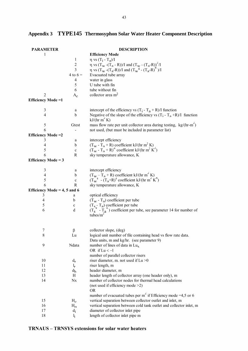
43
TRNAUS – TRNSYS extensions for solar water heaters
Appendix 3 TYPE145 Thermosyphon Solar Water Heater Component Description
PARAMETER DESCRIPTION
1 Efficiency Mode
1 vs (Ti - Ta)/I
2 vs (T
_
w -(Ta - R))/I and (T
_
w - (Ta-R))2/I
3 vs (T
_
w -(Ta-R))/I and (T
_
w4 - (Ta-R)
4 )/I
4 to 6 = Evacuated tube array
4 water in glass
5 U tube with fin
6 tube without fin
2 Ac collector area m2
Efficiency Mode =1
3 a intercept of the efficiency vs (Ti - Ta + R)/I function
4 b Negative of the slope of the efficiency vs (Ti - Ta +R)/I function
kJ/(hr m2
K)
5 Gtest mass flow rate per unit collector area during testing, kg/(hr-m2)
6 - not used, (but must be included in parameter list)
Efficiency Mode =2
3 a intercept efficiency
4 b (T
_
w - Ta + R) coefficient kJ/(hr m2 K)
5 c (T
_
w - Ta + R)2 coefficient kJ/(hr m
2 K
2)
6 R sky temperature allowance, K
Efficiency Mode = 3
3 a intercept efficiency
4 b (T
_
w – Ta + R) coefficient kJ/(hr m2 K)
5 c (T
_
w4
- (Ta+R)4 coefficient kJ/(hr m
2 K
4)
6 R sky temperature allowance, K
Efficiency Mode = 4, 5 and 6
3 a optical efficiency
4 b (T
_
w - Ta) coefficient per tube
5 c (T
_
s - Ta) coefficient per tube
6 d (T
_
s4 - Ta
4 ) coefficient per tube, see parameter 14 for number of
tubes/m2
7 collector slope, (deg)
8 Lu logical unit number of file containing head vs flow rate data.
Data units, m and kg/hr. (see parameter 9)
9 Ndata number of lines of data in Lus OR if Lu
number of parallel collector risers
10 dr riser diameter, m. not used if Lu >0
11 lr riser length, m
12 dh header diameter, m
13 H header length of collector array (one header only), m
14 Nx number of collector nodes for thermal head calculations
(not used if efficiency mode >2)
OR
number of evacuated tubes per m2 if Efficiency mode =4,5 or 6
15 Hc vertical separation between collector outlet and inlet, m
16 Ho vertical separation between cold tank outlet and collector inlet, m
17 di diameter of collector inlet pipe
18 li length of collector inlet pipe m

44
TRNAUS – TRNSYS extensions for solar water heaters
19 Nb1 number of right angle bends (or equivalent) in inlet pipe
20 Ui loss coefficient of collector inlet pipe, based on pipe outer diameter,
kJ/(hr-m2-K)
21 do diameter of collector outlet pipe, m
22 lo length of collector outlet pipe, m
23 Nb2 number of right angle bends (or equivalent) in collector outlet pipe
24 Uo loss coefficient of collector outlet pipe, based on pipe outer diameter,
kJ/(hr-m2-K)
25 Tank HX
Mode
1 complete mixing of heated fluid at return level, direct connection.
2 fully stratified inlet
3 not available for thermosyphon mode
4 collector loop wrap around heat exchanger
5 Collector coil in tank heat exchanger
6 Collector loop horizontal tank in tank heat exchanger
7 load mixing in bottom of tank (at Hc level),direct connection collector
return fully stratified
8 Collector loop heat exchanger in tank with measured UA
characteristics
26 Vt tank volume, m3
27 Ht tank height (vertical cylinder), Tank diameter (horizontal cylinder),
inner tank diameter for mode 6 heat exchanger m
28 Hr height of collector return to tank above bottom of the tank,
OR for HX mode 3;
height of top of heat pipe condenser above bottom of tank, m
OR for HX Modes 4 and 5
height of heat exchanger inlet above bottom of tank, m.
OR for HX Mode 6; if set =0 then fluid in the mantle is assumed to
rise or fall in the mantle to its thermal equilibrium level before
passing over the mantle area.
29 - Not used (but must be included in parameter list)
30 Not used (but must be included in parameter list)
31 tw kw tank wall thickness times wall conductivity, kJ/(hr K)
32 Tank Configuration
1 vertical cylinder
2 horizontal cylinder
33 UA overall UA for tank, (kJ/(hr-K)
34 ri insulation thickness ratio between the top and sides of a vertical tank
OR
insulation thickness ratio between top and bottom for a horizontal
tank
35 Ti initial temperature of preheat portion of the tank, C
36 Hc height of cold inlet above the bottom of the tank, m
37 Qhe auxiliary input rating, kJ/hr
38 Ha height of auxiliary above the bottom of the tank, m
39 Ht height of thermostat above the bottom of the tank, m
40 Tset thermostat set temperature, C (also initial temperature for section of
tank above element)
41 Tdb temperature dead band for auxiliary heater, K
42 UAf conductance for heat loss to gas flue when auxiliary is off
(=0 for electric auxiliary) kJ/(hr K)
43 Vmax maximum size of tank elements during conduction analysis, (fraction
of tank). typically =0.1
44 Tmax dump valve operating temperature, C
45 Tmin dump valve closing temperature, C

45
TRNAUS – TRNSYS extensions for solar water heaters
Tank HX Mode =
1 or 2
Direct connection to tank
46 - Not used (but must be included in parameter list)
47 - Not used (but must be included in parameter list)
48 - Not used (but must be included in parameter list)
49 - Not used (but must be included in parameter list)
50 - Not used (but must be included in parameter list)
Tank HX Mode =
3
Heat pipe condenser specification
Not available in thermosyphon circuit
Tank HX Mode =
4
Wrap around heat exchanger specification (vertical tank only)
46 Dc
diameter of wrap around coil tubing, m
47 Lc
length of wrap around coil m
48 Rb
thermal resistance of coil to tank bonding / metre length, K hr/(kJ
m) (=twall/(kwall A/L)) where A/L = D for full circumference
HX.
49 tw kw
tank wall thickness times wall conductivity, kJ/(hr K)
50 tp kp
heat exchanger tubing wall thickness times wall conductivity
kJ/(hr K)
Tank HX Mode =
5
Coil in tank heat exchanger specification
46 Dc
diameter of coil tubing, m
47 Lc
length of coil, m
48 Rb
conduction thermal resistance of coil wall/ metre length
K hr/(kJ m)
49 -
Not used (but must be included in parameter list)
50 -
Not used (but must be included in parameter list)
Tank HX Mode =
6 & 7
Horizontal tank in tank heat exchanger specification
46 DHX
Inside diameter of outer wall of mantle heat exchanger , m
47 LHX
length of mantle heat exchanger , m
48 Rbond
conduction thermal resistance of tank wall/metre length
K hr m/kJ
1 glasswall
HX wall glass
tt
D k k
49 - Not used (but must be included in parameter list)
50 - Not used (but must be included in parameter list)
Tank HX Mode =
8
Horizontal tank – measured heat exchanger UA
46 DHX
Hydraulic diameter of heat exchanger tubes on collector side
,used for internal friction evaluation, must equal dimension of test
unit, only single tube is considered , m
47 LHX
length of mantle heat exchanger (used for internal friction
evaluation, must equal dimension of test unit), m
48 -
Not used (but must be included in parameter list)
49 UA1 Intercept of UA versus average temperature of heat exchanger

46
TRNAUS – TRNSYS extensions for solar water heaters
kJ/(h K)
50 UA2 Slope of UA versus average temperature of heat exchanger kJ/(h)
51 OPTICAL MODE
0 no incidence angle modification
1 use incidence modifier constant from ASHRAE 93-77
2 modifier data as a function of incidence angle
3 not available
4 bi-axial incidence angle modifier data
5 optical map for collector that is symmetric in the North-South and
East-West planes.
6 optical map for collector symmetric in the East-West plane only
Optical Mode =1
52 Bo incidence angle modifier constant (ASHRAE 93-77)
Optical Mode =2 or 4
52 Lui logical unit containing incidence angle modifier data
53 No number of values of incidence angle in data ( <=25 )
Optical Mode =5 & 6
52 Lui logical unit number of file containing optical data
53 N1 number of values of transverse angles (<=50)
54 N2 number of values of longitudinal angles (<=25)
last - 1 IREV - reverse thermosyphon
0 do not analyse reverse flow
1 analyse reverse flow
2 print detailed output each time step (produces large output file,
only select for short simulations)
last Tt operating temperature for thermosyphon flow restriction valve
(set >100 for no flow restriction ), C
INPUT NO DESCRIPTION
1 It incident radiation on collector aperture (kJ/(hr-m2)
2 Ih horizontal total radiation (kJ/(hr-m2)
3 Id horizontal diffuse radiation (kJ/(hr-m2)
4 solar beam incidence angle to collector, (deg)
5 ground reflectance
6 Ta ambient temperature, C
7 Tl temperature of load input to tank, C
8 ml mass flow rate from load, (kg/hr)
9 Tenv environmental temperature for losses from storage C
10 - enable signal for auxiliary heater
Efficiency Modes 4 to 6 or Optical Modes 2 to 6
11 Idt diffuse radiation incident on collector aperture, (kJ/hr m2)
12 z solar zenith angle, (deg)
13 az solar azimuth angle, (deg)
14 azc collector azimuth angle, (deg)
OUTPUT
DESCRIPTION
1 Th
Temperature of hot fluid entering tank C
2 Qu
useful output energy from collector (at collector outlet) kJ/hr
3 Tr
temperature of fluid returned to collector, C
4 mh
mass flow rate to collector, kg/hr
5 Td
temperature of fluid delivered to load, C

47
TRNAUS – TRNSYS extensions for solar water heaters
6 ml
mass flow rate to load, kg/hr
7 Qenv
rate of heat loss from tank, kJ/hr
8 Qsup
rate of energy supply to load kJ/hr
9 E
change of internal energy of tank since start of simulation
10 Qaux
rate of auxiliary input to tank, kJ/hr
11 Qin
rate of energy input to tank (collector output - pipe losses) kJ/hr
12 T
average storage temperature, C
13 V < 45°C
load volume delivered at temperatures less than 45°C m3/hr
14 V < 57°C
load volume delivered at temperatures less than 57°C m3/hr
15 E < 45°C
load energy delivered at temperatures less than 45°C kJ/hr
16 E < 57°C
load energy delivered at temperatures less than 57°C kJ/hr
17 Tret
input temperature to collector loop, C.
= tank bottom temperature for mc>0
= tank temperature at level of collector return to tank if mc<0
18 Ed
energy dumped due to tank over heating, kJ/hr
19 Qrev
potential heat loss due to reverse flow , kJ/hr (not removed from
tank)

48
TRNAUS – TRNSYS extensions for solar water heaters
Appendix 4 TYPE137 Heat Pump with Solar Boosted Evaporator
PARAMETER DESCRIPTION
1 IU Logical unit number for heat pump rating data
2 N1 number of condenser temperatures in heat pump performance data
file
3 N2 number of evaporator temperatures in heat pump performance
data file
INPUT DESCRIPTION
1 Qe evaporator heat gain kJ/hr
2 Qc condenser heat transfer kJ/hr
3 Tcx water temperature over depth of condenser °C
4 Tex ambient temperature adjacent to evaporator °C
5 ONOFF heat pump motor switch
OUTPUT DESCRIPTION
1 Te evaporator temperature, °C
2 Tc condenser temperature °C
3 Wcom compressor power kJ/hr

49
TRNAUS – TRNSYS extensions for solar water heaters
Appendix 5 TRNAUS data deck for heat pipe collector modelling
CONSTANTS 13
LAT = -34 REF = 0.2 SLOPE = 34 AZIMUTH = 0 HE = 0.2 HTH = 0.25
MODE = 3 TDB = 3 TSET = 61 UA = 9 FLOW = 500 IR = 2 COND = 3.3
UNIT 9 TYPE 9 Weather data reader
PARAMETERS 13
6 1 -4 10 0 -5 10 0 6 .1 0 4 1
(1X,3F2.0,3F3.0)
* Output 9,4 is horizontal global irradiation
* Outout 9,6 is ambient temperature
UNIT 16 TYPE 16 Radiation processor
PARAMETERS 7
3 3 1 LAT 4871 2 1
INPUTS 6
9,4 9,19 9,20 0,0 0,0 0,0
0 0 0 REF SLOPE AZIMUTH
UNIT 1 TYPE 101 Heat pipe collector model
* Collector modelled on basis of experimental test data for collector/heat pipe module
* see section 5.1.2 if collector has been tested without the heat pipe.
* Collector flow rate is fixed at 500 l/hr
* Collector output will be negative at night however the heat pipe condenser model
* in the stratified storage tank will only accept positive heat input
PARAMETERS 12
1 1 AC 4.18 2 .627 10 0 3 0 1 0
INPUTS 10
38,1 0,0 0,0 9,6 16,7 16,4 16,5 0,0 16,9 0,0
20 FLOW FLOW 20 0 0 0 REF 0 SLOPE
UNIT 38 TYPE 138 Stratified tank
* Positive heat output from collector is given by output 38,9.
* The following parameter list applies to a heat pipe collector for which the collector is
* specified in terms of Twater - Te
* where Twater is the water temperature outside the heat pipe condenser,
* The condenser length is set to a large value (100* actual) to eliminate the thermal resistance of
* the heat pipe condenser, which is included in the collector coefficients in TYPE1)
PARAMETERS 24
MODE .325 .44 .1 4.18 1000 COND 2 UA IR 35 0 12960 HE HTH TSET
TDB 0 .1 100 95 .02 20 0
INPUTS 6
1,1 1,2 17,1 25,2 9,6 0,0
20 FLOW 20 0 20 1
* 17,1 is cold water temperature
* 25,2 is load flow rate

50
TRNAUS – TRNSYS extensions for solar water heaters
Appendix 6 TRNAUS data deck for energy load control
Control of load draw off from TRNSYS water tanks is limited to volume specification. However in order to
compare two systems, simulations of operation when both systems are supplying the same energy load is necessary.
Energy load control can be built into a TRNSYS simulation by using a thermal mixing valve. The program will
iterate on the volume draw off until a desired energy load is achieved.
Note :- energy load control significantly increases the program execution time (up to 4 times for some systems).
An example of part of a TRNSYS deck for load energy control is shown below.
CONSTANTS 1
TLOAD=45
* TLOAD is the mixing valve set temperature.
* The exact value of TLOAD is not critical provided it is in the range Tcold < TLOAD < Thot
* where Tcold is the cold water make up temperature and
* Thot is the minimum hot water delivery temperature.
UNIT 14 TYPE 14 LOAD FRACTION MORNING PEAK
* Load distribution each day, % / hr
* Australian standard load pattern specified in AS2813.
PARAMETERS 60
0,0 7,0
7,30 8,30
8,18 9,18
9,0 11,0
11,5 12,5
12,7 13,7
13,0 15,0
15,10 16,10
16,0 17,0
17,12 18,12
18,13 19,13
19,0 21,0
21,0 22,0
22,5 23,5
23,0 24,0
UNIT 15 TYPE 14 MONTHLY ENERGY
* daily average monthly energy load, MJ/day
PARAMETERS 48
0,28.8 744,28.8
744,29.6 1416,29.6
1416,31.1 2160,31.1
2160,32.2 2880,32.2
2880,34.6 3624,34.6
3624,36.6 4344,36.6
4344,37.4 5088,37.4
5088,36.3 5832,36.3
5832,35.2 6552,35.2
6552,34.3 7296,34.3
7296,31.9 8016,31.9
8016,29.4 8760 29.4
UNIT 17 TYPE 14 MONTHLY TMAIN
* Monthly cold water temperature
PARAMETERS 48

51
TRNAUS – TRNSYS extensions for solar water heaters
0,24.4 744,24.4
744,24.3 1416,24.3
1416,23.2 2160,23.2
2160,21.3 2880,21.3
2880,17 3624,17
3624,14.2 4344,14.2
4344,13.2 5088,13.2
5088,13.4 5832,13.4
5832,17.4 6552,17.4
6552,19.3 7296,19.3
7296,20.2 8016,20.2
8016,23.8 8760,23.8
UNIT 18 TYPE 15 LOAD FLOW RATE GENERATOR
* This unit computes the load volume required to achieve the specified energy load for a fixed delivery
* temperature of TLOAD
PARAMETERS 16
-1 TLOAD 0 4 0 -7 2 0 1 -1 239.2 1 -1 100 2 -4
INPUTS 3
17,1 15,1 14,1
0.0 0.0 0.0
UNIT 25 TYPE 11 TEMPERING VALVE
* This unit computes the load volume required to achieve the desired energy delivery
PARAMETERS 2
4 4
INPUTS 4
17,1 18,1 1,3 0,0
20 0 TSET TLOAD
* Third input to UNIT25 is the variable load delivery temperature in this example it is the output
*temperature of a stratified storage tank
UNIT 1 TYPE 138 STRATIFIED TANK
PARAMETERS 24
MODE .34 1.47 HCOL 4.18 1000 COND 1 UA IR TSET .0 3 HAUX HTH TSET TDB
0 .1 100 95 .01 50 0
INPUTS 6
34,2 21,2 17,1 25,2 9,6 26,1
80 500 20 0 20 1

52
TRNAUS – TRNSYS extensions for solar water heaters
Appendix 7 TYPE 176 User Over-ride of Booster Operation
PARAMETER DESCRIPTION
1 NSTK Number of oscillation of the controller in a timestep after which o
(the first output) ceases to change
2 tp Time period for which the output signal is set to 1 after the input
falls below Tset. If the time period is negative the module will act
as a one-shot controller for variable specified as input number 3.
If tp is negative only one boost cycle will occur, then the control
will be locked out until midnight. (models the SEA-Vic one-shot
per day boost specification).
3 Tset Set point value. Output will be set to 1 when input 1 falls below
Tset
INPUT NO DESCRIPTION
1 T1 Control temperature
2 i Input control function (Output 1 [176,1])
3 Variable controlled by output 1 (eg auxiliary power) – for one-
shot operation. If the operating time period tp > 0 this variable is
ignored.
OUTPUT DESCRIPTION
1 o Output control function
An example of the application of this routine to control the operation of an electric booster in a Type 138 tank is
shown below. Two control functions are combined in the control signal auxonoff, a time of day boost controlled
by a TYPE14 time sequence signal ([14,1]) and a one-shot boost controlled by the TYPE176 module.
Constants 2
* one-shot mode specified (ontime negative
ontime = -1
* 45C operation temperature
Tset=45
unit 176 type 176 one cycle boost
parameters 3
5 ontime Tset
Inputs 3
138,3 176,1 138,8
tset 0 0
eqn 1
auxonoff=max([14,1],[176,1])

53
TRNAUS – TRNSYS extensions for solar water heaters
Appendix 8 TYPE 177 Delay timer
This type is used to set a control signal to 0 for a specified time after the first input becomes 1. If the input drops
to 0 then the time delay is cancelled and the output goes to 1.
PARAMETER DESCRIPTION
1 delay time period for which the output signal is set to 0 after the first
input turns on (hrs)
INPUT NO DESCRIPTION
1 In1 Control signal
2 Out2 Output 2 [177,2]
OUTPUT DESCRIPTION
1 o output control function
2 out2
An example of the application of this routine to set a control signal (eg for operation of an electric booster) for 5
hours after a pump turns on (2,1)is shown below.
Constants 1
* delay timer
delay = 48
unit 77 type 177
parameters 1
delay
Inputs 2
2,1 77,2
0 0

54
TRNAUS – TRNSYS extensions for solar water heaters
Appendix 9 TYPE 178 Event detection
This type is used to set a control signal to 1 if the first input has not exceed a threshold level in the previous
specified time period.
PARAMETER DESCRIPTION
1 Threshold Threshold level for checking input(1)
2 Period Time period over which the first input is checked against the
threshold hrs
INPUT NO DESCRIPTION
1 In1 Variable to be checked against the threshold level
OUTPUT DESCRIPTION
1 o output control function
An example of the application of this routine to set a control signal to 1 if the input has not exceeded the threshold
for the past 3 days. This could be to initiate a tank sterilization boost to the threshold temperature if the input
signal say the temperature in a tank (60,23) has been below the threshold for the last 3 days.
Constants 2
* Threshold level
Threshold = 60
Period= 3*24
unit 78 type 178
parameters 2
threshold period
Inputs 1
60,23
0

55
TRNAUS – TRNSYS extensions for solar water heaters
Appendix 10 TYPE 102 Differential controller with three maximum limits
This controller generates a control function o that can have values of 0 or 1. The control value is a function of
the difference between input 1 and input 7. The new value of is dependent on whether i = 0 or 1. The controller
is used with o connected to
i (input 5).
The controller also applies limits to inputs 2,3 and 7.
Differential control
Input 1 – input 7 controlled in dead band ranges set by input 5 and input 6 (same as TYPE2 but
differential is taken between inputs 1 and 7 rather than inputs 1 and 2 as in TYPE2.
Limits
Limit on value of input 2 set by parameter 4 o =0 if Input2 > par4
Limit of value of input 3 set by parameter 2 o =0 if Input3 > par2
Limit on value of input 7 set by parameter 3 o =0 if Input7 > par3
PARAMETER DESCRIPTION
1 NSTK Number of oscillations of the controller in a timestep after which
the output ceases to change.
2 Tmax1 Limit for input 3
3 Tmax2 Limit for input 7
4 Tmax3 Limit for input 2
INPUT NO DESCRIPTION
1 TH Upper input temperature
2 Check variable 1
3 Check variable 2
4 o Input control function
5 Upper dead band temperature difference (input 1 – input 7)
6 Lower dead band temperature difference (input 1 – input 7)
7 Lower input temperature
OUTPUT DESCRIPTION
1 o output control function
An example of the application of this routine to set a control signal to 1 based on a collector output temperature
signal [1,1] and another temperature [60,32] and two additional variables [5,1] and [4,1]to be checked for high
values is given below
UNIT 20 TYPE 102 Falling film flow controller
PARAMETERS 4
5 Tcol_max Ttank_max Tret_max
INPUTS 7
* differential control function applied between input 1 and input 7
* limit on collector outlet temperature set by par(2) and input 3
* limit on Ttop average is set by parameter 3 and input 7
* limit on Thxout is set by parameter 4 and input 2
1,1 5,1 4,1 20,1 0,0 0,0 60,32
25 25 25 0 Ton Toff 20

56
TRNAUS – TRNSYS extensions for solar water heaters
Appendix 11 Gas Boosted Water Heater Simulation
*GAS STORAGE SYSTEM
Constants 2
QMR = 0.6 * 3.6 (kJ/h)
*Tank heat loss equivalent to gas tank maintenance rate
UA = QMR*Effic/45 (kJ/h)/K
eqns 4
*Daily energy delivery
* PKLOAD = peak winter load MJ/day
*dyengy = daily total energy load
dyengy = [13,1] * PKLOAD
*Load volume at load temp TLOAD
*This load flow is used in conjunction with a TYPE11 tempering valve to set required energy
*delivery from the tank
*TLOAD = outlet temperature of mixing valve (use 45)
*effy = gas burner efficiency kJ/hr
*burner = gas burner consumption rate kJ/hr
ldflw = dyengy * [14,1] / (TLOAD-[17 ,I]) /0.00418
*gas burner rate
auxgas=burner*effic
*gas consumption
gas= [5,8]/effy
UNIT 25 TYPE 11 TEMPERING VALVE
*Sets up load volume for required energy load
PARAMETERS 2
4 8
INPUTS 4
17,1 ldflw 5,3 0,0
20 0 TSET TLOAD
UNIT 5 TYPE 138
*Gas storage water heating system
PARAMETERS 21
7 VOL H 0 4.18 1000 KWALL 1 UA 1.2
TSET HCOLD AUX 0 0.05 TSET Tdb 0.1 95 90
INPUTS 6
0,0 0,0 17,1 25,2 9,6 0,0
0 0 TSET 0 20 1

57
TRNAUS – TRNSYS extensions for solar water heaters
Appendix 12 TYPE 160 - Modified Type60 detailed storage tank
TYPE160 is a modification of the TYPE60 tank with the following additional features
Thermostat setting as an input rather than a parameter
Selection of mantle or falling film heat exchangers in the collector loop.
PARAMETER DESCRIPTION
1 to second last As for TYPE60
last hx 1 = collector loop mantle heat exchanger
2 = collector loop falling film heat exchanger
other values ignored
NOTE: Parameter 10 (Tset) is ignored
INPUT NO DESCRIPTION
1 to second last As for TYPE60
last Tset Thermostat set temperature (parameter 18 ignored)
OUTPUT DESCRIPTION
As for TYPE60

58
TRNAUS – TRNSYS extensions for solar water heaters
Appendix 13 TYPE 99 – Thermosyphon sidearm heat exchanger
TYPE99 is a model of a thermosyphon sidearm heat exchanger based on measured
effectiveness and pressure drop characteristics. This model is used in conjunction with a
TYPE138 tank.
PARAMETER DESCRIPTION
1 Hcol Height of thermosyphon sidearm input to tank
2 Hhx Vertical height of sidearm heat exchanger
3 H1 Vertical height of bottom of heat exchanger above the outlet
INPUT NO DESCRIPTION
1 T_coldin Temperature of thermosyphon loop inlet to heat exchanger (°C)
2 T_hotin Temperature of hot pumped flow inlet to heat exchanger (°C)
3 Flow_hot Pump flow rate on hot side of heat exchanger (kg/h)
4 Ht Thermosyphon pressure in tank, (Pa)
OUTPUT DESCRIPTION
1 xout Temperature of thermosyphon loop outlet from heat exchanger
(°C)
2 P_Tout Outlet temperature of hot pumped flow from heat exchanger (°C)
3 x_flow Sidearm thermosyphon flow rate (kg/h)
Eqn 1
Ht = [138,11]
unit 99 type 99 Sidearm HX
parameters 3
Hcol Hhx H1
inputs 4
T_coldin T_hotin Flow_hot Ht
20 20 0 10000