
Optical measurement of absolute flatness with the - IOPscience
5
Journal of Physics: Conference Series OPEN ACCESS Optical measurement of absolute flatness with the deflectometric measurement systems at PTB To cite this article: Gerd Ehret et al 2013 J. Phys.: Conf. Ser. 425 152016 View the article online for updates and enhancements. You may also like Influence of the air’s refractive index on precision angle metrology with autocollimators Ralf D Geckeler, Petr Ken, Andreas Just et al. - Evaluation of the deformation value of an optical flat under gravity Yohan Kondo and Youichi Bitou - Transmitted wavefront testing with large dynamic range based on computer-aided deflectometry Daodang Wang, Ping Xu, Zhidong Gong et al. - Recent citations Note: Autocollimation with ultra-high resolution and stability using telephoto objective together with optical enlargement and beam drift compensation Fan Zhu et al - Application of advanced shearing techniques to the calibration of autocollimators with small angle generators and investigation of error sources T. Yandayan et al - Application of the differential Fabry–Perot interferometer in angle metrology M Çelik et al - This content was downloaded from IP address 187.73.14.151 on 02/12/2021 at 02:40
Transcript of Optical measurement of absolute flatness with the - IOPscience

Journal of Physics Conference Series
OPEN ACCESS
Optical measurement of absolute flatness with thedeflectometric measurement systems at PTBTo cite this article Gerd Ehret et al 2013 J Phys Conf Ser 425 152016
View the article online for updates and enhancements
You may also likeInfluence of the airrsquos refractive index onprecision angle metrology withautocollimatorsRalf D Geckeler Petr Ken Andreas Just etal
-
Evaluation of the deformation value of anoptical flat under gravityYohan Kondo and Youichi Bitou
-
Transmitted wavefront testing with largedynamic range based on computer-aideddeflectometryDaodang Wang Ping Xu Zhidong Gonget al
-
Recent citationsNote Autocollimation with ultra-highresolution and stability using telephotoobjective together with optical enlargementand beam drift compensationFan Zhu et al
-
Application of advanced shearingtechniques to the calibration ofautocollimators with small anglegenerators and investigation of errorsourcesT Yandayan et al
-
Application of the differential FabryndashPerotinterferometer in angle metrologyM Ccedilelik et al
-
This content was downloaded from IP address 1877314151 on 02122021 at 0240
Optical measurement of absolute flatness with the
deflectometric measurement systems at PTB
Gerd Ehret Michael Schulz Maik Baier Arne Fitzenreiter
Physikalisch-Technische Bundesanstalt (PTB)
Bundesallee 100 38116 Braunschweig Germany
E-mail gerdehretptbde
Abstract Highly accurate flatness measurements are needed for synchrotron optics optical
flats or optical mirrors Recently two new scanning deflectometric flatness measurement
systems have been installed at the Physikalisch-Technische Bundesanstalt (PTB) The two
systems (one system for horizontal and the other for vertical specimens) can measure
specimens with sizes up to one metre with an expected uncertainty in the sub-nanometre range
In addition to the classical deflectometric procedure also the lsquoextended shear angle difference
(ESAD)rsquo and the lsquoexact autocollimation deflectometric scanning (EADS)rsquo procedures are
implemented The lateral resolution of scanning deflectometric techniques is limited by the
aperture of the angle measurement system usually an autocollimator with typical apertures of a
few millimetres With the EADS procedure the specimen is scanned with an angular null
instrument which has the potential to improve the lateral resolution down to the sub-millimetre
region A new concept and design of an appropriate angular null instrument are presented and
discussed
1 Introduction
Angle-based measurement systems such as the Nanometre Optical Component Measuring Machine
(NOM) at the Institute for Nanometre Optics and Technology (INT) of the Helmholtz Zentrum Berlin
(HZB) (formerly Bessy) [1] the upgraded Long Trace Profiler-II (LTP-II) at the Advanced Light
Source (ALS) Optical Metrology Laboratory (OML) [2] the upgraded LTP of the Japan Synchrotron
Radiation Research Institute at SPring-8 [3] the Diamond-NOM [4] or the Deflectometric Flatness
Reference (DFR) systems at PTB [5 6] are used to characterize optical surfaces with nanometre or
even down to sub-nanometre uncertainties Especially the measurement of grazing incidence optics of
synchrotrons requires highest accuracies
Based on the lsquoextended shear angle difference (ESAD)rsquo system at PTB [7] and the Nanometre
Optical Metrology (NOM) system at HZB two new deflectometric systems have recently been
installed at PTB [5 6] The systems have different operating modes like the difference deflectometric
procedures also named ESAD [7] and the direct deflectometric mode used in the NOM
Deflectometric scanning procedures are typically based on scanning a pentaprism or a
corresponding double mirror unit (DMU) across the specimen thereby measuring the surface slopes
with an angle measuring system These 90deg beam deflectors eliminate ndash to a great extent ndash guidance
errors of the scanning stages which are required to attain topography measurements with sub-
nanometre uncertainty The precise alignment of the optics as well as the mechanics is therefore
necessary [8] For the precise alignment of the pentaprism or the corresponding DMU to the optical
11th International Conference on Synchrotron Radiation Instrumentation (SRI 2012) IOP PublishingJournal of Physics Conference Series 425 (2013) 152016 doi1010881742-659642515152016
Published under licence by IOP Publishing Ltd 1
axis sophisticated procedures are available [9-11] A drawing and a photo of the system which is
mainly used for measurement of horizontally orientated specimens is shown in Figure 1
Figure 1 Drawing and photo of the system for horizontally aligned specimens
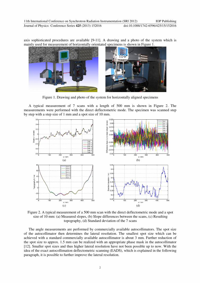
A typical measurement of 7 scans with a length of 500 mm is shown in Figure 2 The
measurements were performed with the direct deflectometric mode The specimen was scanned step
by step with a step size of 1 mm and a spot size of 10 mm
(a) (b)
(c) (d)
Figure 2 A typical measurement of a 500 mm scan with the direct deflectometric mode and a spot
size of 10 mm (a) Measured slopes (b) Slope differences between the scans (c) Resulting
topography (d) Standard deviation of the 7 scans
The angle measurements are performed by commercially available autocollimators The spot size
of the autocollimator then determines the lateral resolution The smallest spot size which can be
achieved with a standard commercially available autocollimator is about 3 mm Further reduction of
the spot size to approx 15 mm can be realized with an appropriate phase mask in the autocollimator
[12] Smaller spot sizes and thus higher lateral resolution have not been possible up to now With the
idea of the exact autocollimation deflectometric scanning (EADS) which is explained in the following
paragraph it is possible to further improve the lateral resolution
11th International Conference on Synchrotron Radiation Instrumentation (SRI 2012) IOP PublishingJournal of Physics Conference Series 425 (2013) 152016 doi1010881742-659642515152016
2
2 The EADS principle and its possibility for a smaller scanning beam The exact autocollimation deflectometric scanning (EADS) method is shown in Figure 3 The
scanning beam of autocollimator AC1 only acts as a null instrument The surface under test is kept
perpendicular to the scanning beam by tilting the specimen with a piezoactuator The EADS principle
is implemented in the new scanning deflectometric reference systems The procedure as well as the
controller is described in more detail in [13] The autocollimator AC1 provides 25 readings per
second As piezoactuator a low voltage piezoactuator with an integrated position sensor from Physik
Instrumente (PI) GmbH amp Co KG is used The control deviations are usually less than
001 arcseconds after 4 cycles of the control loop but typically we use 7 cycles at each measurement
point which requires in total about 10 seconds This corresponds to a measurement rate of 01 points
per second In the present setup the EADS is rather slow but with an optimized control setup this
time could be improved and even a control mechanism lsquoon the flyrsquo could be realized
Figure 3 EADS principle (AC autocollimator) [13]
The main advantages of this method are that the optical path length of the angle measuring device
(AC2) is constant that this angle can be measured with better accuracy since a greater measurement
aperture can be used and that a smaller spot size can be realised for the null instrument
3 Concept and design of an appropriate null angle instrument We aim at a scanning beam diameter of less than 1 mm for a scan length of up to 1 m Just using a
Gaussian beam is not possible because the Gaussian beam always has a certain divergence of
)( 02 wπλθ = with the wavelength λ
and the beam waist 0w This means the smaller the beam
waist the greater is the divergence of the beam For example a He-Ne laser with a beam waist of
=0w 05 mm has a beam radius of 084 mm after one meter propagation In comparison a He-Ne laser
with a beam waist of =0w 005 mm already has a beam radius of 4 mm after one meter propagation
A new concept for realizing a small scanning beam is shown in Figure 4 The unit with the null
Figure 4 New concept for a small scanning beam
11th International Conference on Synchrotron Radiation Instrumentation (SRI 2012) IOP PublishingJournal of Physics Conference Series 425 (2013) 152016 doi1010881742-659642515152016
3
instrument is mounted directly at the carriage of the scanning stage Due to the guidance errors of the
scanning stage the mirror is tilted The autocollimator (AC) directly measures the difference between
the guidance of the scanning stage and the tilting of the specimen which represents the slope of the
specimen The null sensor has a fixed optical path length and thus a small scanning beam of less than
1 mm seems to be realistic
4 Conclusion and outlook Two new deflectometric scanning systems were set up at PTB A typical measurement was shown
where sub-nanometre repeatability was demonstrated The concept illustrated in Figure 4 will be
realized now and it is expected that measurements with the deflectometric reference system down to a
lateral resolution of less than 1 mm can be carried out
5 Acknowledgments This work is part of the EMRP project IND10 (httpwwwptbdeemrpind10-homehtml) We thank
the EMRP for the financial support of part of this work The EMRP is jointly funded by the EMRP
participating countries within EURAMET and the European Union
References [1] Siewert F Lammert H and Zeschke T 2008 Chapter 11 ldquoThe Nanometer Optical Component Measuring
Machinerdquo in Erko A Idir M Krist T and Michette A G Modern Developments in X-Ray and Neutron
Optics Springer Series in Optical Sciences 137 pp 193-200
[2] Kirschman J L Domning E E McKinney W R Morrison G Y Smith B V and Yashchuk V V 2008
Performance of the upgraded LTP-II at the ALS Optical Metrology Laboratory Proc of SPIE 7077 pp
70770A-1-12
[3] Senba Y Kishimoto H Ohashi H Yumoto H Zeschke T Siewert F Goto S and Ishikawa T 2010
Upgrade of long trace profiler for characterization of high-precision X-ray mirrors at SPring-8
Nuclear Instruments and Methods in Physics Research Section A Accelerators Spectrometers
Detectors and Associated Equipment 616(2-3) pp 237-240
[4] Alcock S G Sawhney K J S Scott S Pedersen U Walton R Siewert F Zeschke T Senf F Noll T and
Lammert H 2009 The Diamond-NOM A non-contact profiler capable of characterizing optical figure
error with sub-nanometre repeatability Nuclear Instruments and Methods in Physics Research Section
A 616 (2-3) pp 224-228
[5] Schulz M Ehret G Stavridis M and Elster C 2010 Concept design and capability analysis of the new
Deflectometric Flatness Reference at PTB Nucl Instr and Methods in Phys Res A616 pp 134-139
[6] Ehret G Schulz M Stavridis M and Elster C 2012 Deflectometric systems for absolute flatness
measurements at PTB Meas Sci Technol 23 094007 (8pp)
[7] Geckeler R D and Weingaumlrtner I 2002 Sub-nm Topography Measurement by Deflectometry Flatness
Standard and Wafer Nanotopography Proc of SPIE 4779 pp 1-12
[8] Ehret G Schulz M Fitzenreiter A Baier M Joumlckel W Stavridis M and Elster C 2011 Alignment methods
for ultraprecise deflectometric flatness metrology Proc of SPIE 8082 808213-1-8
[9] Geckeler R D 2007 Optimal use of pentaprisms in highly accurate deflectometric scanning Meas Sci
Technol 18 pp 115-125
[10] Barber S K Morrison G Y Yashchuk V V Gubarev M V Geckeler R D Buchheim J Siewert F and
Zeschke T 2011 Developmental long trace profiler using optimally aligned mirror based pentaprism
Optical Engineering 50(5) pp 053601-1-10
[11] Barber S K Geckeler R D Yashchuk V V Gubarev M V Buchheim J Siewert F and Zeschke T 2011
Optimal alignment of mirror based pentaprism for scanning deflectometric devices Optical
Engineering 50(7) 0073602-1-8
[12] Fuumltterer G 2005 Autokollimationsfernrohr und Verfahren zur Abbildung einer Messmakse hierfuumlr
German Patent DE102005018983
[13] Schulz M Ehret G and Fitzenreiter A 2010 Scanning deflectometric form measurement avoiding path-
dependent angle measurement errors Journal of the European Optical Society Rapid Publications
wwwjeosorgindexphpjeos_rparticleview10026596
11th International Conference on Synchrotron Radiation Instrumentation (SRI 2012) IOP PublishingJournal of Physics Conference Series 425 (2013) 152016 doi1010881742-659642515152016
4

Optical measurement of absolute flatness with the
deflectometric measurement systems at PTB
Gerd Ehret Michael Schulz Maik Baier Arne Fitzenreiter
Physikalisch-Technische Bundesanstalt (PTB)
Bundesallee 100 38116 Braunschweig Germany
E-mail gerdehretptbde
Abstract Highly accurate flatness measurements are needed for synchrotron optics optical
flats or optical mirrors Recently two new scanning deflectometric flatness measurement
systems have been installed at the Physikalisch-Technische Bundesanstalt (PTB) The two
systems (one system for horizontal and the other for vertical specimens) can measure
specimens with sizes up to one metre with an expected uncertainty in the sub-nanometre range
In addition to the classical deflectometric procedure also the lsquoextended shear angle difference
(ESAD)rsquo and the lsquoexact autocollimation deflectometric scanning (EADS)rsquo procedures are
implemented The lateral resolution of scanning deflectometric techniques is limited by the
aperture of the angle measurement system usually an autocollimator with typical apertures of a
few millimetres With the EADS procedure the specimen is scanned with an angular null
instrument which has the potential to improve the lateral resolution down to the sub-millimetre
region A new concept and design of an appropriate angular null instrument are presented and
discussed
1 Introduction
Angle-based measurement systems such as the Nanometre Optical Component Measuring Machine
(NOM) at the Institute for Nanometre Optics and Technology (INT) of the Helmholtz Zentrum Berlin
(HZB) (formerly Bessy) [1] the upgraded Long Trace Profiler-II (LTP-II) at the Advanced Light
Source (ALS) Optical Metrology Laboratory (OML) [2] the upgraded LTP of the Japan Synchrotron
Radiation Research Institute at SPring-8 [3] the Diamond-NOM [4] or the Deflectometric Flatness
Reference (DFR) systems at PTB [5 6] are used to characterize optical surfaces with nanometre or
even down to sub-nanometre uncertainties Especially the measurement of grazing incidence optics of
synchrotrons requires highest accuracies
Based on the lsquoextended shear angle difference (ESAD)rsquo system at PTB [7] and the Nanometre
Optical Metrology (NOM) system at HZB two new deflectometric systems have recently been
installed at PTB [5 6] The systems have different operating modes like the difference deflectometric
procedures also named ESAD [7] and the direct deflectometric mode used in the NOM
Deflectometric scanning procedures are typically based on scanning a pentaprism or a
corresponding double mirror unit (DMU) across the specimen thereby measuring the surface slopes
with an angle measuring system These 90deg beam deflectors eliminate ndash to a great extent ndash guidance
errors of the scanning stages which are required to attain topography measurements with sub-
nanometre uncertainty The precise alignment of the optics as well as the mechanics is therefore
necessary [8] For the precise alignment of the pentaprism or the corresponding DMU to the optical
11th International Conference on Synchrotron Radiation Instrumentation (SRI 2012) IOP PublishingJournal of Physics Conference Series 425 (2013) 152016 doi1010881742-659642515152016
Published under licence by IOP Publishing Ltd 1
axis sophisticated procedures are available [9-11] A drawing and a photo of the system which is
mainly used for measurement of horizontally orientated specimens is shown in Figure 1
Figure 1 Drawing and photo of the system for horizontally aligned specimens
A typical measurement of 7 scans with a length of 500 mm is shown in Figure 2 The
measurements were performed with the direct deflectometric mode The specimen was scanned step
by step with a step size of 1 mm and a spot size of 10 mm
(a) (b)
(c) (d)
Figure 2 A typical measurement of a 500 mm scan with the direct deflectometric mode and a spot
size of 10 mm (a) Measured slopes (b) Slope differences between the scans (c) Resulting
topography (d) Standard deviation of the 7 scans
The angle measurements are performed by commercially available autocollimators The spot size
of the autocollimator then determines the lateral resolution The smallest spot size which can be
achieved with a standard commercially available autocollimator is about 3 mm Further reduction of
the spot size to approx 15 mm can be realized with an appropriate phase mask in the autocollimator
[12] Smaller spot sizes and thus higher lateral resolution have not been possible up to now With the
idea of the exact autocollimation deflectometric scanning (EADS) which is explained in the following
paragraph it is possible to further improve the lateral resolution
11th International Conference on Synchrotron Radiation Instrumentation (SRI 2012) IOP PublishingJournal of Physics Conference Series 425 (2013) 152016 doi1010881742-659642515152016
2
2 The EADS principle and its possibility for a smaller scanning beam The exact autocollimation deflectometric scanning (EADS) method is shown in Figure 3 The
scanning beam of autocollimator AC1 only acts as a null instrument The surface under test is kept
perpendicular to the scanning beam by tilting the specimen with a piezoactuator The EADS principle
is implemented in the new scanning deflectometric reference systems The procedure as well as the
controller is described in more detail in [13] The autocollimator AC1 provides 25 readings per
second As piezoactuator a low voltage piezoactuator with an integrated position sensor from Physik
Instrumente (PI) GmbH amp Co KG is used The control deviations are usually less than
001 arcseconds after 4 cycles of the control loop but typically we use 7 cycles at each measurement
point which requires in total about 10 seconds This corresponds to a measurement rate of 01 points
per second In the present setup the EADS is rather slow but with an optimized control setup this
time could be improved and even a control mechanism lsquoon the flyrsquo could be realized
Figure 3 EADS principle (AC autocollimator) [13]
The main advantages of this method are that the optical path length of the angle measuring device
(AC2) is constant that this angle can be measured with better accuracy since a greater measurement
aperture can be used and that a smaller spot size can be realised for the null instrument
3 Concept and design of an appropriate null angle instrument We aim at a scanning beam diameter of less than 1 mm for a scan length of up to 1 m Just using a
Gaussian beam is not possible because the Gaussian beam always has a certain divergence of
)( 02 wπλθ = with the wavelength λ
and the beam waist 0w This means the smaller the beam
waist the greater is the divergence of the beam For example a He-Ne laser with a beam waist of
=0w 05 mm has a beam radius of 084 mm after one meter propagation In comparison a He-Ne laser
with a beam waist of =0w 005 mm already has a beam radius of 4 mm after one meter propagation
A new concept for realizing a small scanning beam is shown in Figure 4 The unit with the null
Figure 4 New concept for a small scanning beam
11th International Conference on Synchrotron Radiation Instrumentation (SRI 2012) IOP PublishingJournal of Physics Conference Series 425 (2013) 152016 doi1010881742-659642515152016
3
instrument is mounted directly at the carriage of the scanning stage Due to the guidance errors of the
scanning stage the mirror is tilted The autocollimator (AC) directly measures the difference between
the guidance of the scanning stage and the tilting of the specimen which represents the slope of the
specimen The null sensor has a fixed optical path length and thus a small scanning beam of less than
1 mm seems to be realistic
4 Conclusion and outlook Two new deflectometric scanning systems were set up at PTB A typical measurement was shown
where sub-nanometre repeatability was demonstrated The concept illustrated in Figure 4 will be
realized now and it is expected that measurements with the deflectometric reference system down to a
lateral resolution of less than 1 mm can be carried out
5 Acknowledgments This work is part of the EMRP project IND10 (httpwwwptbdeemrpind10-homehtml) We thank
the EMRP for the financial support of part of this work The EMRP is jointly funded by the EMRP
participating countries within EURAMET and the European Union
References [1] Siewert F Lammert H and Zeschke T 2008 Chapter 11 ldquoThe Nanometer Optical Component Measuring
Machinerdquo in Erko A Idir M Krist T and Michette A G Modern Developments in X-Ray and Neutron
Optics Springer Series in Optical Sciences 137 pp 193-200
[2] Kirschman J L Domning E E McKinney W R Morrison G Y Smith B V and Yashchuk V V 2008
Performance of the upgraded LTP-II at the ALS Optical Metrology Laboratory Proc of SPIE 7077 pp
70770A-1-12
[3] Senba Y Kishimoto H Ohashi H Yumoto H Zeschke T Siewert F Goto S and Ishikawa T 2010
Upgrade of long trace profiler for characterization of high-precision X-ray mirrors at SPring-8
Nuclear Instruments and Methods in Physics Research Section A Accelerators Spectrometers
Detectors and Associated Equipment 616(2-3) pp 237-240
[4] Alcock S G Sawhney K J S Scott S Pedersen U Walton R Siewert F Zeschke T Senf F Noll T and
Lammert H 2009 The Diamond-NOM A non-contact profiler capable of characterizing optical figure
error with sub-nanometre repeatability Nuclear Instruments and Methods in Physics Research Section
A 616 (2-3) pp 224-228
[5] Schulz M Ehret G Stavridis M and Elster C 2010 Concept design and capability analysis of the new
Deflectometric Flatness Reference at PTB Nucl Instr and Methods in Phys Res A616 pp 134-139
[6] Ehret G Schulz M Stavridis M and Elster C 2012 Deflectometric systems for absolute flatness
measurements at PTB Meas Sci Technol 23 094007 (8pp)
[7] Geckeler R D and Weingaumlrtner I 2002 Sub-nm Topography Measurement by Deflectometry Flatness
Standard and Wafer Nanotopography Proc of SPIE 4779 pp 1-12
[8] Ehret G Schulz M Fitzenreiter A Baier M Joumlckel W Stavridis M and Elster C 2011 Alignment methods
for ultraprecise deflectometric flatness metrology Proc of SPIE 8082 808213-1-8
[9] Geckeler R D 2007 Optimal use of pentaprisms in highly accurate deflectometric scanning Meas Sci
Technol 18 pp 115-125
[10] Barber S K Morrison G Y Yashchuk V V Gubarev M V Geckeler R D Buchheim J Siewert F and
Zeschke T 2011 Developmental long trace profiler using optimally aligned mirror based pentaprism
Optical Engineering 50(5) pp 053601-1-10
[11] Barber S K Geckeler R D Yashchuk V V Gubarev M V Buchheim J Siewert F and Zeschke T 2011
Optimal alignment of mirror based pentaprism for scanning deflectometric devices Optical
Engineering 50(7) 0073602-1-8
[12] Fuumltterer G 2005 Autokollimationsfernrohr und Verfahren zur Abbildung einer Messmakse hierfuumlr
German Patent DE102005018983
[13] Schulz M Ehret G and Fitzenreiter A 2010 Scanning deflectometric form measurement avoiding path-
dependent angle measurement errors Journal of the European Optical Society Rapid Publications
wwwjeosorgindexphpjeos_rparticleview10026596
11th International Conference on Synchrotron Radiation Instrumentation (SRI 2012) IOP PublishingJournal of Physics Conference Series 425 (2013) 152016 doi1010881742-659642515152016
4