Optical Filters Polarization and Filters - Semrock · 5 Polarization –linear polarization •...
19
www.semrock.com Optical Filters Polarization and Filters Turan Erdogan, PhD (CTO and Co-founder) Semrock, A Unit of IDEX Corporation May 31, 2011
Transcript of Optical Filters Polarization and Filters - Semrock · 5 Polarization –linear polarization •...

www.semrock.com
Optical Filters
Polarization and Filters
Turan Erdogan, PhD (CTO and Co-founder)
Semrock, A Unit of IDEX Corporation
May 31, 2011

2
Sometimes polarization does not matter
• Often we can sufficiently characterize the spectral performance of an
optical filter by determining simply the amount of light intensity (I) it
transmits (T(λ)) and it reflects (R(λ))
• T and R are called the “intensity transmission” and “intensity reflection”
coefficients
• At normal incidence, polarization does not matter
Iin
filter
IR = R(l)Iin
IT = T(l)Iin

3
Polarization matters sometimes
• Filters are used at non-normal incidence to separate light into two paths
– for example, a dichroic beamsplitter sends different wavelength bands
into different directions
• Often, especially when the light is incoherent or randomly polarized for
other reasons, the intensity transmission and reflection coefficients are
sufficient to characterize the spectral performance of the filter
Iin
dichroic
IR = R(l)Iin
IT = T(l)Iin

4
Polarization matters sometimes
• However, if the intensity coefficients T and R are very different for the
two states of polarization (s and p) AND if the polarization of the output
light matters (often it doesn’t), then the transmission and reflection
should be analyzed separately for each state of polarization
Is,T = Ts(l)Iin
Is,R = Rs(l)Iin
Ip,T = Tp(l)Iin
Ip,R = Rp(l)Iin
Iin

5
Polarization – linear polarization
• Since light is a transverse wave, there are two distinct directions transverse to
the propagation direction in which it may oscillate
We can view a light wave at a “fixed time” (say t = 0):
The total electric field is the sum of the two orthogonally polarized components:
Looking down the z axis (in the + z direction) and at t = 0, the total field E traces out a
line in the x-y plane – hence the name “linear polarization”
tkzsinAyx yxEEE

6
Polarization – linear polarization
• Another way of looking at the electric field is to sit at a “fixed position” and
observe the evolution of the total field vector E in time
At z = 0 we see the total field can be written:
• When the two components Ex and Ey have unequal amplitudes, we still find
linear polarization, but the line traced by E is at angle a with respect to x
tAyx 2sinyxEEE
x
y
A
Aatan

7
Polarization – circular polarization
• If the two components have equal amplitude, but are out of phase by /2, the
total field E traces out a circle
In the “fixed time” picture, the total field at various locations looks like:
The field also traces out a circle in time at a “fixed position”

8
Polarization – elliptical polarization
• In the most general case the two components do not have equal amplitude
(Ax Ay) and they are out of phase (d 0). Because the tip of the electric field
vector traces out an ellipse, this state is called “elliptical polarization”
Some examples of more general states of elliptical polarization are shown below
tkzAxx sinxE d tkzAyy sinyE yx EEE

9
Polarization – polarizers
• A simple polarizer transmits only a single orientation of linear polarization, and
blocks the rest of the light
There are many different types of polarizers, but most are based on the same
physical principle: the polarizing material allows charges (electrons) to freely move in
one direction but not the other
When the electric field of a light wave encounters the
polarizer, the component parallel to the direction
along which charge flows freely (Ey in the example)
causes the charges to oscillate, thereby absorbing
energy and preventing that component from being
transmitted. Since charges can not respond to the
orthogonal component, that component is passed

10
Polarization – birefringence
• A material that has different indexes of refraction for light polarized along
different orientations is said to be “birefringent”
For example, suppose linearly polarized light with a 45 is transmitted through a
material of index nx for light polarized along x and ny for light polarized along y
In general the light emerges in a different state of elliptical polarization
If the length is chosen such that
tzknA xx sinxE tzknA yy sinyE Lknyy Lknxx
the light emerges circularly polarized! This is called a “quarter-wave plate”
2 LnkLnnk xyxy or 4 Ln
11
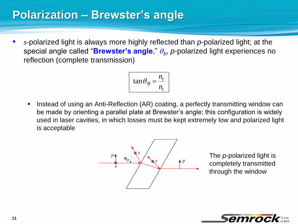
Polarization – Brewster’s angle
• s-polarized light is always more highly reflected than p-polarized light; at the
special angle called “Brewster’s angle,” qB, p-polarized light experiences no
reflection (complete transmission)
Instead of using an Anti-Reflection (AR) coating, a perfectly transmitting window can
be made by orienting a parallel plate at Brewster’s angle; this configuration is widely
used in laser cavities, in which losses must be kept extremely low and polarized light
is acceptable
i
tB
n
nqtan
The p-polarized light is
completely transmitted
through the window

12
Light at an interface between two media
• Definition of a Ray: The path along which light energy is
transmitted from one point to another.
Fermat’s Principle of Least Time: when light travels between
two points, it takes the path that is traversed in the least time.
The Law of Reflection:
When a ray is reflected off of an interface, the
angle of reflection is equal to the angle of
incidence.
The Law of Refraction:
When a ray is transmitted across an interface
between two media with different refractive
indexes, the product of the index and the sine of
the ray angle is equal on both sides.
ri qq ttii nn qq sinsin “Snell’s Law”

13
How much light crosses the interface?
• Reflection and Transmission of Light Rays at an Interface
If light is incident in a medium of index ni at an angle qi, so that the transmitted ray in a
medium of index nt is at angle qt, then the fraction of the amplitude (not power)
reflected off of the interface (for parallel polarization) is:
ttii
ttii
i
r
nn
nn
E
Er
coscos
coscos
2rR RT 1
The fraction of the power reflected off of
and transmitted through the interface is:

14
Total Internal Reflection at an interface
• Total Internal Reflection (TIR) occurs when light is incident from a higher-index
medium onto a lower-index medium and the angle of incidence becomes so large
that Snell’s Law fails.
• The Critical Angle, or qc, is the angle of incidence that just makes the angle of
transmission equal to 90 degrees.
For an incident angle greater than the critical angle, all of the light is reflected, such
that R = |r| = 1
ti
i
tc
nn
n
n
q
for
arcsin

15
Reflection for different polarizations of light
• When light is not normally incident on an interface, different polarizations are
reflected by different amounts – this is called “Fresnel reflection”
The “s” component is perpendicular to and the “p” component is parallel to the “plane
of incidence,” or the plane that contains the incident, transmitted, and reflected rays
ttii
ttii
s
srs
nn
nnr
coscos
coscos
E
Ε
tiit
tiit
p
pr
pnn
nnr
coscos
coscos
E
Ε
Fresnel
(amplitude)
reflection
coefficients:
Fresnel
(power)
reflection
coefficients:

16
State of polarization changed by a filter
• Now it should be apparent why reflection and transmission can change
the state of polarization (when the incident light is polarized)
A difference in rs and rp (or ts and tp) changes the amount of s and p light
A difference in φs and φp acts like birefringence
Es,t = ts(l)eifs,t(l)Es,in
Es,r = rs(l)eifs,r(l)Es,in
Ep,t = tp(l)eifp,t(l)Ep,in
Ep,r = rp(l)eifp,r(l)Ep,in
IT = |Et|2
IR = |Er|2
Iin = |Ein|2
Es,in
Ep,in

17
Short-wave-pass dichroic for “SHG” imaging
• Excellent dispersion and polarization properties make this filter ideal for
Second Harmonic Generation (SHG) imaging
• Optimized for excitation at ~ 810 nm and imaging of the nonlinear
scattered light (which is not fluorescence!) at ~ 405 nm
Configuration for using
a short-wave-pass
dichroic beamsplitter

18
Short-wave-pass dichroic for “SHG” imaging
• Carefully controlled polarization dependence to maintain a high
degree of linear polarization for both reflected laser light and transmitted
signal light for all polarization orientations
Allows one to vary the
polarization state of the
laser while measuring a
like-polarized signal
beam for the utmost in
signal-to-noise ratio
Maintaining linear polarization for light
transmitted through FF720-SDi01 at 405 nm

19
Thank you!