
Measurement of T-violating Transverse Muon Polarization in K + → p 0 m + n Decays at J-PARC
1
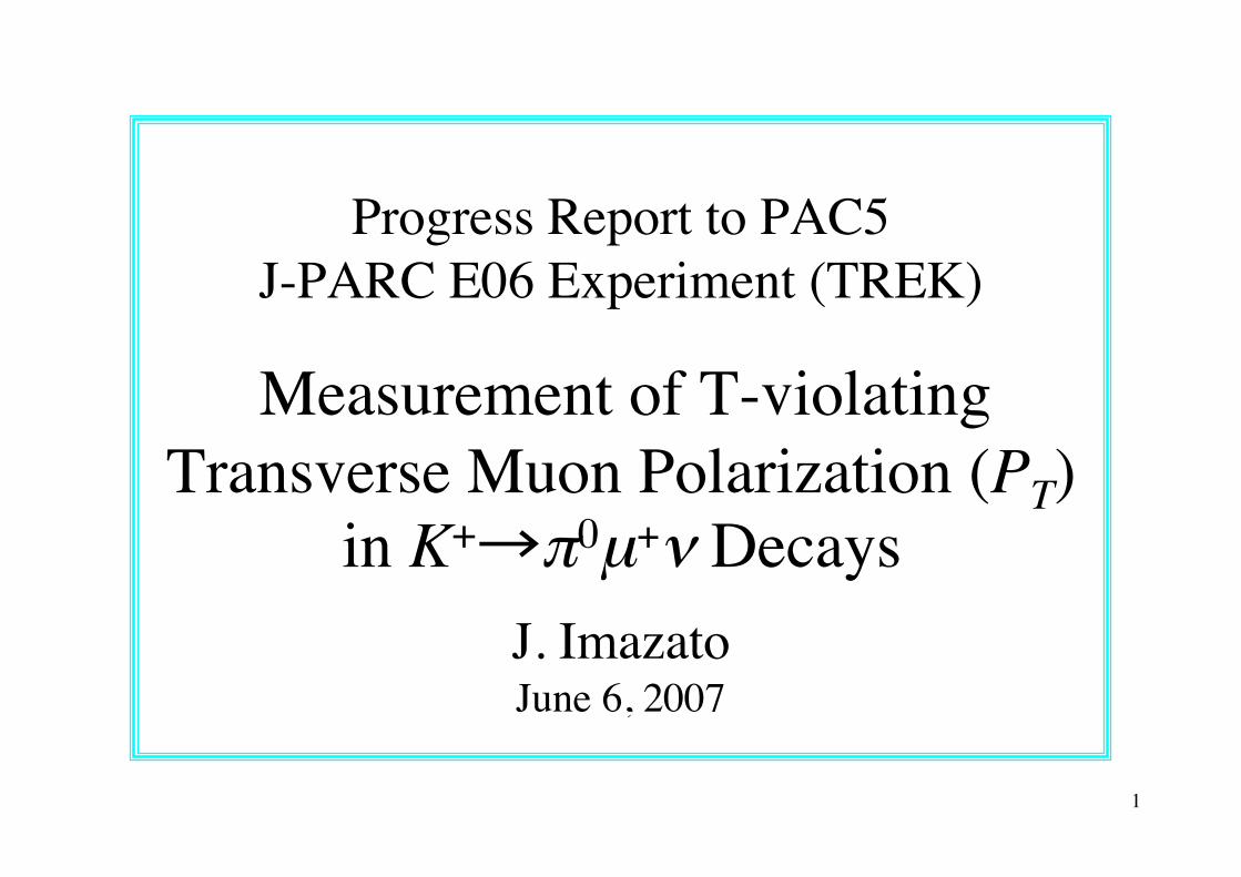
Progress Report to PAC5J-PARC E06 Experiment (TREK)
Measurement of T-violatingTransverse Muon Polarization (PT)
in K+→π0µ+ν DecaysJ. ImazatoJune 6, 2007

2
1. Outline of the TREK experiment2. Theoretical model descriptions of PT3. Funding and collaboration4. Study of beamline5. Progress of detector design and R&D6. Plan for this year7. Summary
3
Outline of the TREK experiment

4
Transverse µ+ polarization in Κµ3K+→π0µ+ν decay
PT is T-odd, and spurious effects from final state interaction are small: PT(FSI) < 10-5 Non-zero PT is a signature of T violation.
Standard Model (SM) contribution to PT : PT(SM) < 10-7
PT in the range 10-3~10-4 is a sensitive probe of CP violation beyond the SM.
There are theoretical models of new physics which allow a sizable PT without conflicting with other experimental constraints.
5
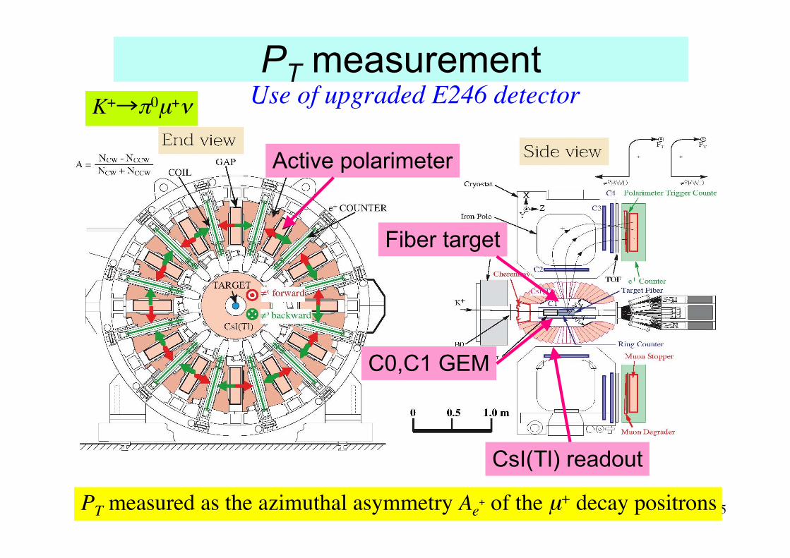
PT measurementUse of upgraded E246 detector
PT measured as the azimuthal asymmetry Ae+ of the µ+ decay positrons
Active polarimeter
Fiber target
C0,C1 GEM
CsI(Tl) readout
K+→π0µ+ν
6
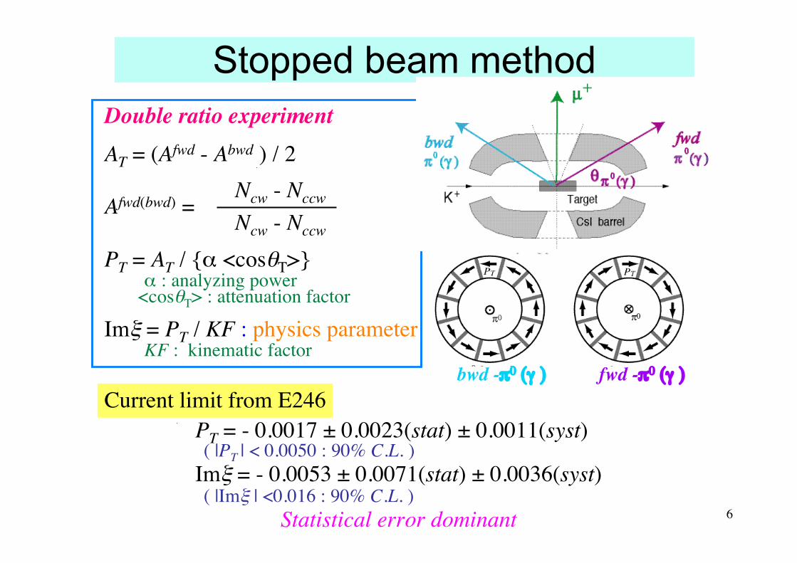
Stopped beam method
PT = - 0.0017 ± 0.0023(stat) ± 0.0011(syst) ( |PT | < 0.0050 : 90% C.L. )Imξ = - 0.0053 ± 0.0071(stat) ± 0.0036(syst) ( |Imξ | <0.016 : 90% C.L. )
Statistical error dominant
Double ratio experimentAT = (Afwd - Abwd ) / 2 Ncw - NccwAfwd(bwd) = Ncw - Nccw
PT = AT / {α <cosθT>} α : analyzing power <cosθT> : attenuation factor
Imξ = PT / KF : physics parameter KF : kinematic factor
bwd -π0 (γ ) fwd -π0 (γ )
Current limit from E246
7
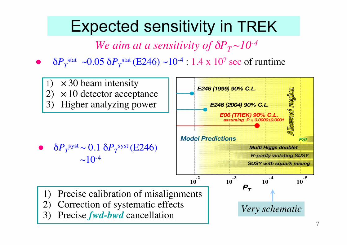
Expected sensitivity in TREK
δPTstat ~0.05 δPT
stat (E246) ~10-4 : 1.4 x 10⁷ sec of runtime
1) Precise calibration of misalignments2) Correction of systematic effects3) Precise fwd-bwd cancellation
1) × 30 beam intensity2) × 10 detector acceptance3) Higher analyzing power
δPTsyst ~ 0.1 δPT
syst (E246) ~10-4
We aim at a sensitivity of δPT ~10-4
Very schematic

8
K1.1BR
K1.1
KL
T1
K0.8 (K1.1-BR) for stopped K+
Use of T1 target sharing with K1.8 and KL Macroscopic time sharing with K1.1 if it would be installed
TREK
IK+ = 2.1 × 10⁶ /s @ 9 µA- 30 GeV protons on T1 K/π ratio > 1.0

9
Theoretical modeldescriptions of PT

10
Exotic scalar interactions
Typical models with scalar interactions allowing a sizable PT :– Multi-Higgs doublet model– SYSY with R-parity violation or large squark mixing
Kinematic factor Generic four fermion interaction Lagrangian analysis
Effective field theory with Wilson coefficients
!"#$ %&!'
|ImGs| / GF < 2.2 x 10⁻⁴
< 1x 10⁻⁵
|(m CS| (!/TeV)2
! 2 x 10⁻³
! 1 x 10⁻⁴

11
Three Higgs doublet model
• c.f. dn , b→sγ ∝ Im(α1β1*), (α1β1*) Im(α1β1*) = -v2
2/v32 Im(γ1α1*)
γ1
α1
E246
TREK goal
B→Xτνb→sγ
Neutro
n EDM
B→Xτν and B→τν at Super-Belle corresponds to PT < 3 x 10⁻⁴
c.f. TREK goal : PT ≤ 1 x 10⁻⁴v2/v3 = mt / mτ
PT is most stringent constraint for Im(γ1α1*) !
___Higgs field v. e. v.

12
SUSY with R-parity violationSuper potential : W = WSMMS + WRPV
Imξ = Im ξl + Im ξd
Relevant parameters and constraints
TREK
E246
|λ∗ 232λ’312|
|λ’∗ 21k λ’ 22k |
PT is a very stringent constraint for these parameters !
13
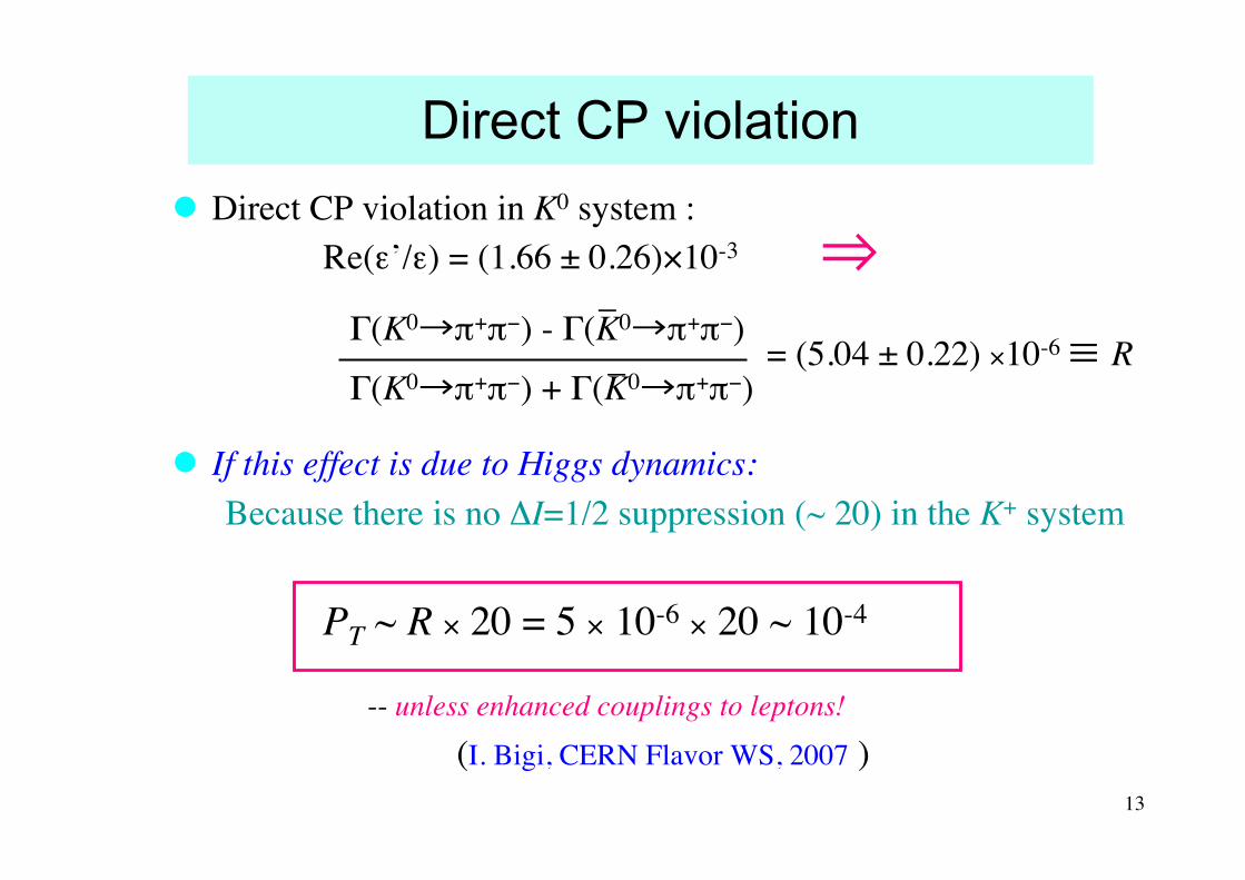
Direct CP violation Direct CP violation in K0 system : Re(ε’/ε) = (1.66 ± 0.26)×10-3
If this effect is due to Higgs dynamics: Because there is no ΔI=1/2 suppression (~ 20) in the K+ system
PT ~ R × 20 = 5 × 10-6 × 20 ~ 10-4
-- unless enhanced couplings to leptons!
(I. Bigi, CERN Flavor WS, 2007 )
_Γ(K0→π+π−) - Γ(K0→π+π−) _Γ(K0→π+π−) + Γ(K0→π+π−)
= (5.04 ± 0.22) ×10-6 ≡ R
⇒

14
Funding and collaboration

15
Comments from last PAC meeting
….. Overall the PAC is impressed with the progress ofE06 and feels that this is an important measurement tobe made at J-PARC. However, before recommendingstage-2 approval, the PAC would like to see progressby the TREK collaboration in securing the funding forthe experiment both internationally and domesticallyand in the collaborative effort with the E14 experimentto define and design workable beamlines for both theKL and K1.1 lines.

16
Status of TREK collaboration
Number of members:– 35 in Jan. ‘08 to 44 now
Collaboration meetings:– Feb. 2006 @ KEK– Oct. 2006 @ MIT (USA)– Feb. 2007 @ KEK– Sep. 2007 @ U.Sask.(Canada)– Feb. 2008 @ KEK– Oct. 2008 @ USC (USA)
International detector R&D– Target : Canada, USA– CsI(Tl) readout : Russia– Polarimeter : Japan
New participation:• Kasetsart University• Jefferson Laboratory• Tokyo Institute of Technology

17
Study of beamline

18
K1.1-BR B1 combined magnet
!"#$%&'()(%& *$$+,)-&$+ !(#$%&.)/0$)(%& 1"2"#%,+/-)(%& 3%&$40.(%&
######6 "66 7+-.(84+ ,%..(84+ 9212
#####:;2<6 ="66#>&%#?-(&@ 7+-.(84+ '(77($04) &%#?-(&
#####:A2B< "B< '(77($04)# (C,%..(84+ &%)#?%%'
We proposed a combine function magnet for B1 to increase the beamline acceptance. Unfortunately, we found n = -6.75 is not feasible because of magnet saturation etc.
B(x)=B0(1-nx/ρ)
1.1 GeV/c
0.8 GeV/c
n=-6.75
Field strength distribution (relative)
• Different dBy/dx values between 0.8 and 1.1 GeV/c• Narrow constant field gradient region fo 1.1 GeV/c
Difficult to adopt the combined function magnet

19
n= 0 solution for B1 n=0 is the only possible solution under the conditions of:
1. 1.1 GeV/c operation in the future2. Already fixed beamline space near T1
Shim was optimized to realize themaximum horizontal width.
We will pursue the Q6 aperture improvement in order to increase the acceptance even by a small amount.
0.6% in the x= ±10 cm range
0.8 GeV/c
1.1 GeV/c
20
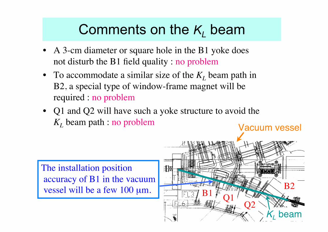
Comments on the KL beam• A 3-cm diameter or square hole in the B1 yoke does
not disturb the B1 field quality : no problem• To accommodate a similar size of the KL beam path in
B2, a special type of window-frame magnet will berequired : no problem
• Q1 and Q2 will have such a yoke structure to avoid theKL beam path : no problem
B1B2
Q1Q2
KL beam
Vacuum vessel
The installation position accuracy of B1 in the vacuum vessel will be a few 100 µm.
21
Progress in detector R&D

22
Progress reported to PAC3 and PAC4 High rate performance :
– GEM prototype beam test at FNAL– CsI(Tl) APD readout beam test at LNS Tohoku (1)– Target MPPC rad. hardness test at RCNP (3)
Polarimeter muon stopper material :– µSR experiment (E1120) at TRIUMF
Systematic error MC studies :– Errors associated with polarimeter misalignments (2)– Back ground suppression
(1) Analysis of pileup events was continued(2) MC analysis with high statistics was performed(3) A more realistic test is now planned at TRIUMF
Since then:
23
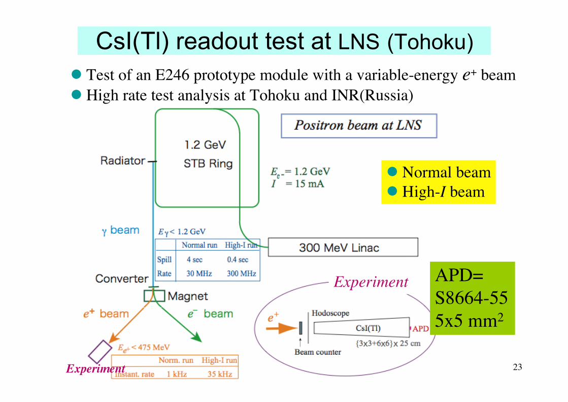
CsI(Tl) readout test at LNS (Tohoku) Test of an E246 prototype module with a variable-energy e+ beam High rate test analysis at Tohoku and INR(Russia)
Experiment
Normal beam High-I beam
Experiment
APD=S8664-555x5 mm2
24
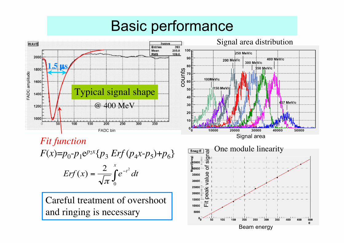
Basic performance
dtexErf
x
t
!"
=0
22)(
#
F(x)=p0-p1ep2x{p3 Erf (p4x-p5)+p6}
Typical signal shape@ 400 MeV
1.5 µs
Fit function
Signal area distribution
One module linearity
Careful treatment of overshoot and ringing is necessary
Signal area
Beam energy
coun
ts
Fit p
eak
valu
e of
sig
nal

25
Analysis of pile-up events
Typical pile-up events in a high rate run
Fit function = a1F(x) + a2F(x+Δx)
(a)
(b)
(c)
Signal area distribution
(a) non-pileup events(b) first pulse in pileup events(c) second pulse in pileup events
similar to (a)
peak position similar to (a) and (b)
Study is underway how to analyze the second pulse. An improved amplifier is developed in any case.
- Separation of two pulses-

26
Analysis efficiency of the first pulse
FADC bin
FADC bin
For pileup pulses with pulse separation larger than 40 bins (0.8 µs), the analysis efficiency is 100%.
For the separation smaller than 60 bins (1.2 µs), there is an influence on the signal area analysis.
No. of events successfully fitted
Average value of area of the first pulse
0.8 µs
1.2 µs
27
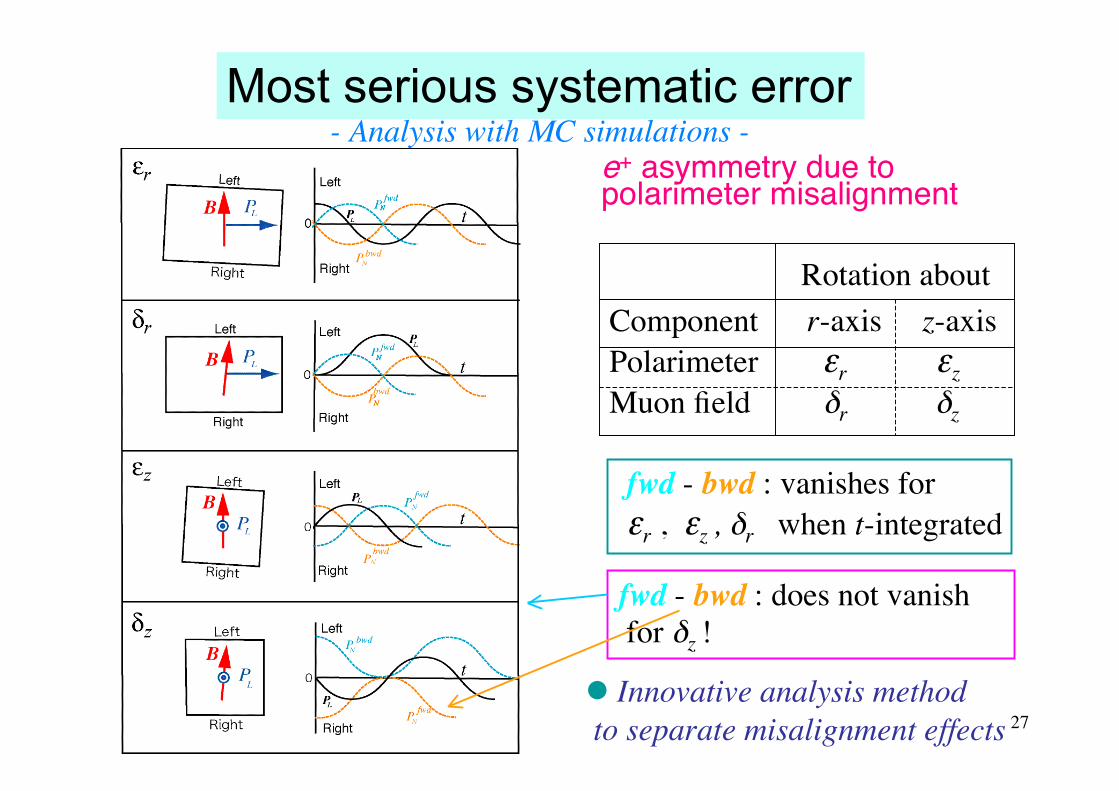
e+ asymmetry due topolarimeter misalignment
Rotation aboutComponent r-axis z-axisPolarimeter εr εzMuon field δr δz
fwd - bwd : vanishes for εr , εz , δr when t-integrated
fwd - bwd : does not vanish for δz !
Most serious systematic error- Analysis with MC simulations -
Innovative analysis method to separate misalignment effects
28
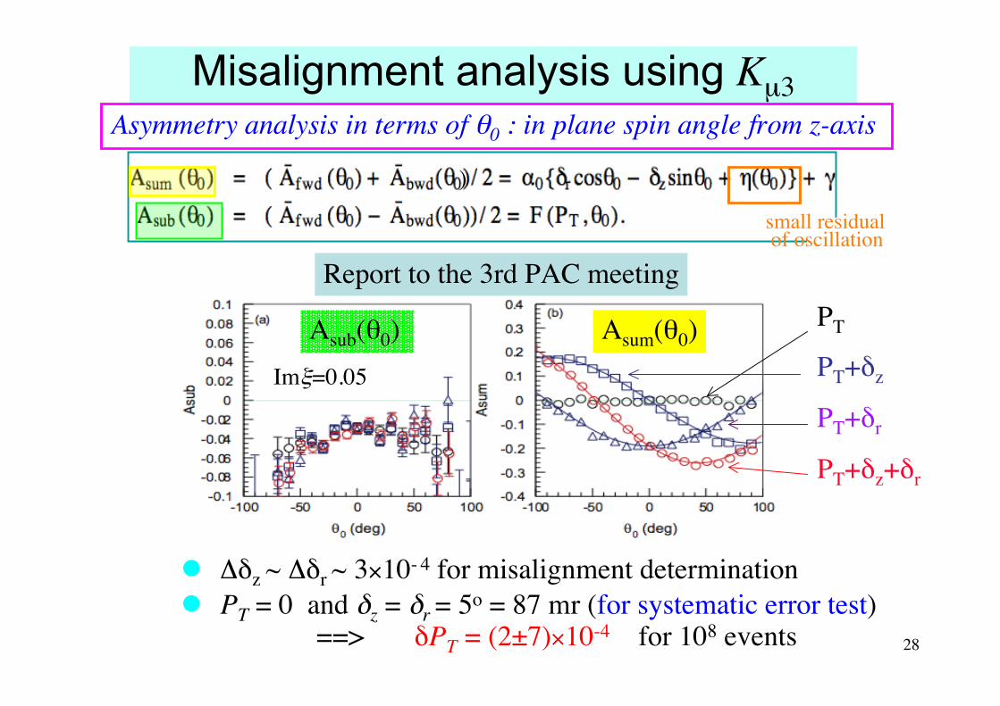
Misalignment analysis using Kµ3
Δδz ~ Δδr ~ 3×10- 4 for misalignment determination
PT = 0 and δz = δr = 5o = 87 mr (for systematic error test) ==> δPT = (2±7)×10-4 for 108 events
Asum(θ0)Asub(θ0)
Asymmetry analysis in terms of θ0 : in plane spin angle from z-axis
PT
PT+δz
PT+δr
PT+δz+δr
small residual of oscillation
Report to the 3rd PAC meeting
Imξ=0.05
)
29
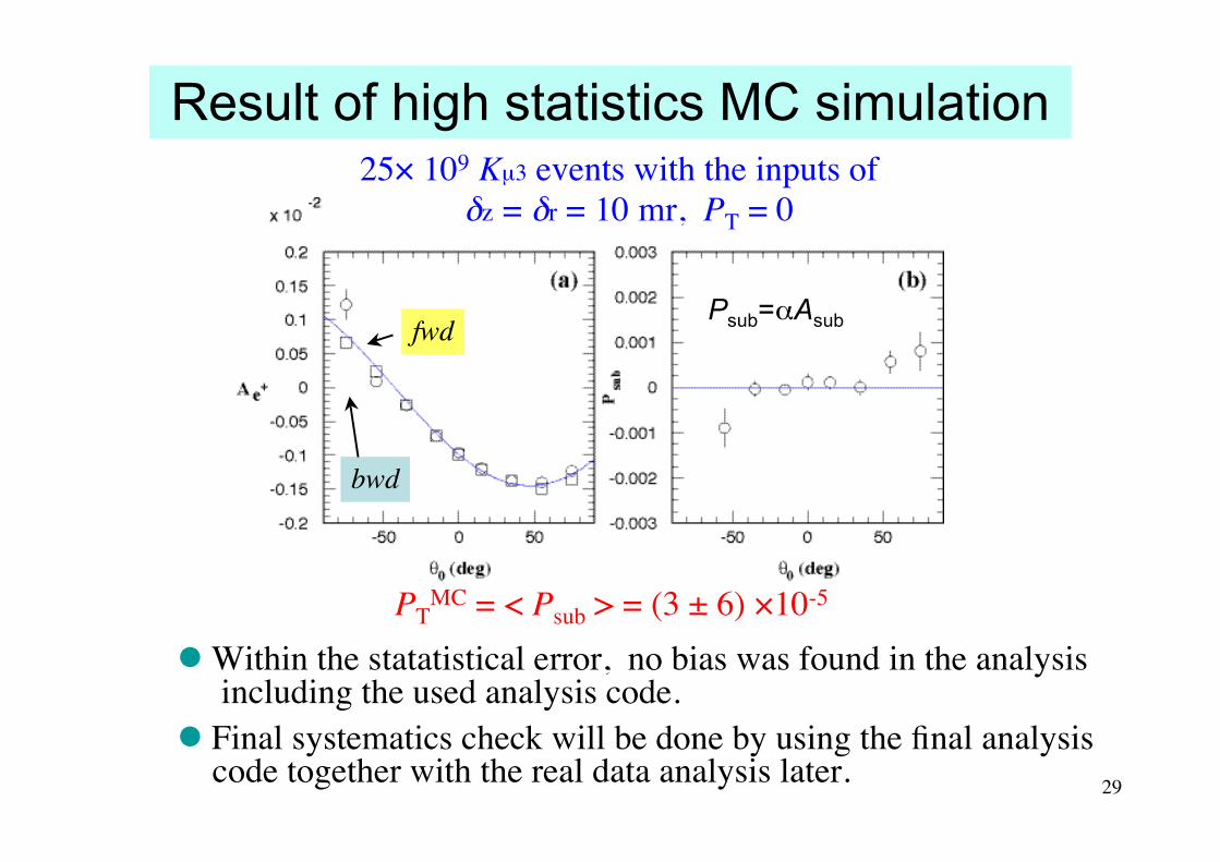
Result of high statistics MC simulation
PTMC = < Psub > = (3 ± 6) ×10-5
fwd
bwd
Within the statatistical error, no bias was found in the analysis including the used analysis code. Final systematics check will be done by using the final analysis code together with the real data analysis later.
25× 109 Kµ3 events with the inputs ofδz = δr = 10 mr, PT = 0
Psub=αAsub

30
Plan for this year

31
Detector preparation(1) Active muon polarimeter
Gap wire chambers Number of plates 31 Plate material Al, Mg or alloy Plate thickness ~ 2.5 mm Plate gap ~ 8 mm Ave. density 0.24 ρAl µ+ stop efficiency ~ 85%
Muon field magnet
32
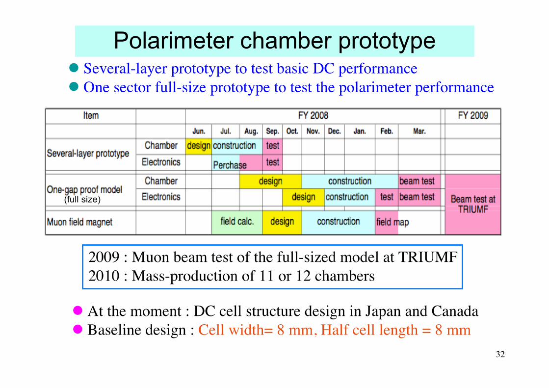
Polarimeter chamber prototype Several-layer prototype to test basic DC performance One sector full-size prototype to test the polarimeter performance
2009 : Muon beam test of the full-sized model at TRIUMF2010 : Mass-production of 11 or 12 chambers
At the moment : DC cell structure design in Japan and Canada Baseline design : Cell width= 8 mm, Half cell length = 8 mm
(full size)
33
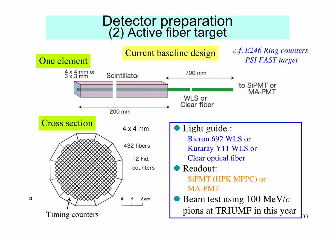
Detector preparation(2) Active fiber target
4 x 4 mm
Current baseline design c.f. E246 Ring counters PSI FAST target
Cross section
Timing counters
One element
Light guide :Bicron 692 WLS orKuraray Y11 WLS orClear optical fiber
Readout:SiPMT (HPK MPPC) orMA-PMT
Beam test using 100 MeV/c pions at TRIUMF in this year
34
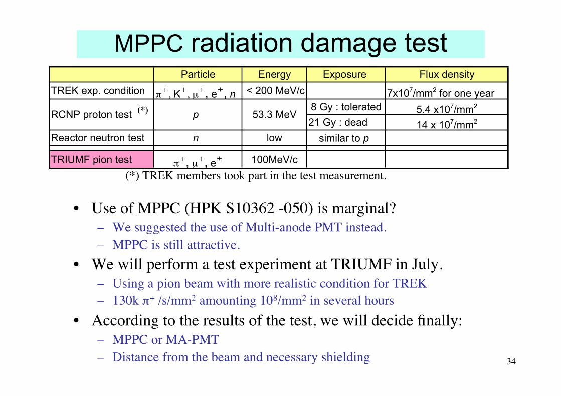
MPPC radiation damage test
• Use of MPPC (HPK S10362 -050) is marginal?– We suggested the use of Multi-anode PMT instead.– MPPC is still attractive.
• We will perform a test experiment at TRIUMF in July.– Using a pion beam with more realistic condition for TREK– 130k π+ /s/mm2 amounting 108/mm2 in several hours
• According to the results of the test, we will decide finally:– MPPC or MA-PMT– Distance from the beam and necessary shielding
Particle Energy Exposure Flux density
TREK exp. condition !!
, K!
, µ!"#$%"#n < 200 MeV/c 7x10⁷/mm2 for one year
8 Gy : tolerated 5.4 x10⁷/mm2
21 Gy : dead 14 x 107/mm2 #
Reactor neutron test n low similar to p
TRIUMF pion test !!"#µ!"#e% 100MeV/c
RCNP proton test p 53.3 MeV(*)
(*) TREK members took part in the test measurement.
35
Summary We have emphasized that PT physics is important. We want to
start the TREK experiment in the early stage of J-PARC. We have succeeded to obtain grants for the TREK experiment, at
least partially. Now we can start the construction of :– Active polarimeter, and the– Scintillating fiber target
We have shown that the most dangerous systematics from thepolarimeter misalignment should be controllable.– Answering the one-year-standing question by PAC
We are continuing detector R&D such as the CsI(Tl) readout andshowed the proposed plan for this year.
We want to accelerate the detector design/construction by gainingfurther grants internationally and domestically. For this the stage-2 approval status is definitely necessary.

36
End of Slides


![Covariant Quantization of Lorentz-Violating Electromagnetismwalsworth.physics.harvard.edu/publications/2012_Hohensee_arxiv.pdf · sical Lorentz-violating theory [12]. In part III,](https://static.fdocuments.in/doc/165x107/5e96cbffbef12e4aa314c0d6/covariant-quantization-of-lorentz-violating-elect-sical-lorentz-violating-theory.jpg)

![Study of nuclear properties with muonic atomsrare decays of the muon violating lepton family number have reached unprecedented sensitivity [7]. With a mass of 105.66 MeV/c2 they are](https://static.fdocuments.in/doc/165x107/61028a1b1747ff668e485dd0/study-of-nuclear-properties-with-muonic-atoms-rare-decays-of-the-muon-violating.jpg)


